
Helping Your Business: Navigating Online Purchasing Resources

OverviewSolidWorks® helps you move through the design cycle easily. With a customizable user interface, each team member team can create their own convenient and efficient SolidWorks environment.
implementation guide:navigating the SolidWorkS uSer interface
t e c h n i c a l p a p e r
www.solidworks.com
Since most 2d cad programs and SolidWorks are applications in the microsoft Windows® environment, tool buttons, toolbars, and the general appearance of the windows look similar. however, many aspects of the environment differ.
Access to toolsthe most efficient method of working in SolidWorks is to use the tools on the toolbars and, when necessary, menus.
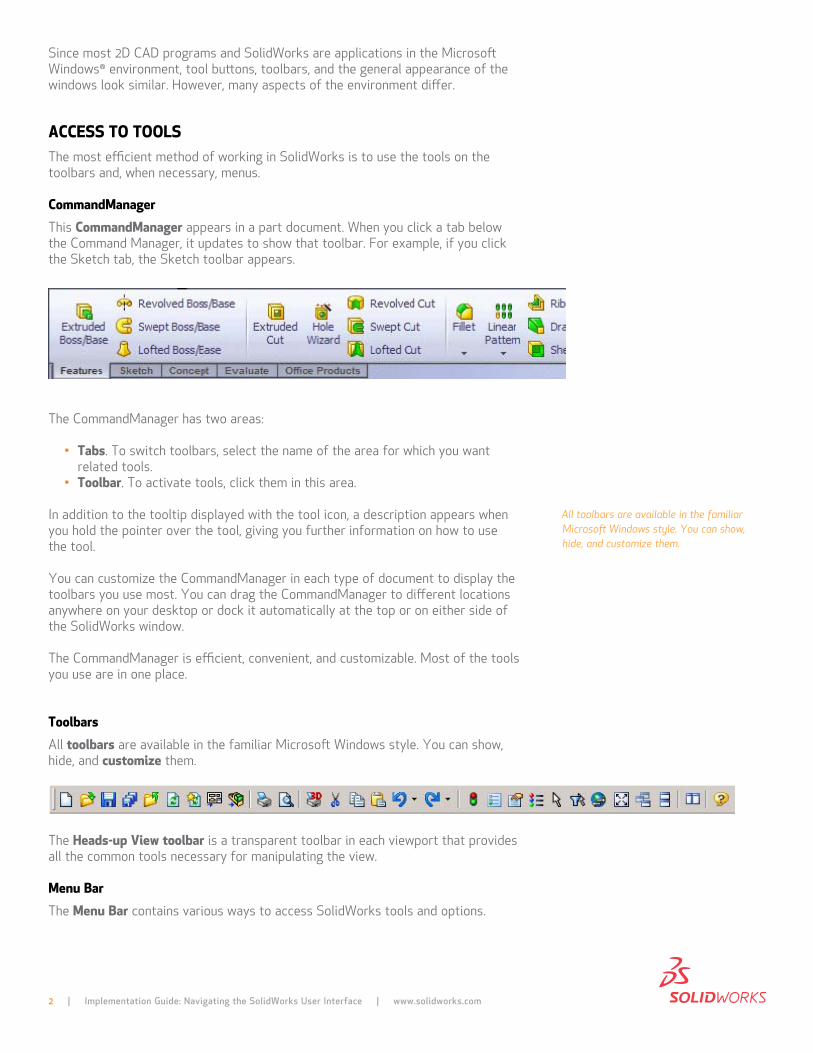
commandManager this commandManager appears in a part document. When you click a tab below the command manager, it updates to show that toolbar. for example, if you click the Sketch tab, the Sketch toolbar appears.
the commandmanager has two areas:
• tabs. to switch toolbars, select the name of the area for which you want related tools.
• toolbar. to activate tools, click them in this area.
in addition to the tooltip displayed with the tool icon, a description appears when you hold the pointer over the tool, giving you further information on how to use the tool.
You can customize the commandmanager in each type of document to display the toolbars you use most. You can drag the commandmanager to different locations anywhere on your desktop or dock it automatically at the top or on either side of the SolidWorks window.
the commandmanager is efficient, convenient, and customizable. most of the tools you use are in one place.
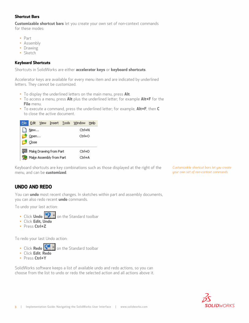
toolbars all toolbars are available in the familiar microsoft Windows style. You can show, hide, and customize them.
the Heads-up View toolbar is a transparent toolbar in each viewport that provides all the common tools necessary for manipulating the view.
Menu Bar the Menu Bar contains various ways to access SolidWorks tools and options.
All toolbars are available in the familiar Microsoft Windows style. You can show, hide, and customize them.
2 | Implementation Guide: Navigating the SolidWorks User Interface | www.solidworks.com
shortcut Bars customizable shortcut bars let you create your own set of non-context commands for these modes:
• part• assembly• drawing• Sketch
Keyboard shortcuts Shortcuts in SolidWorks are either accelerator keys or keyboard shortcuts.
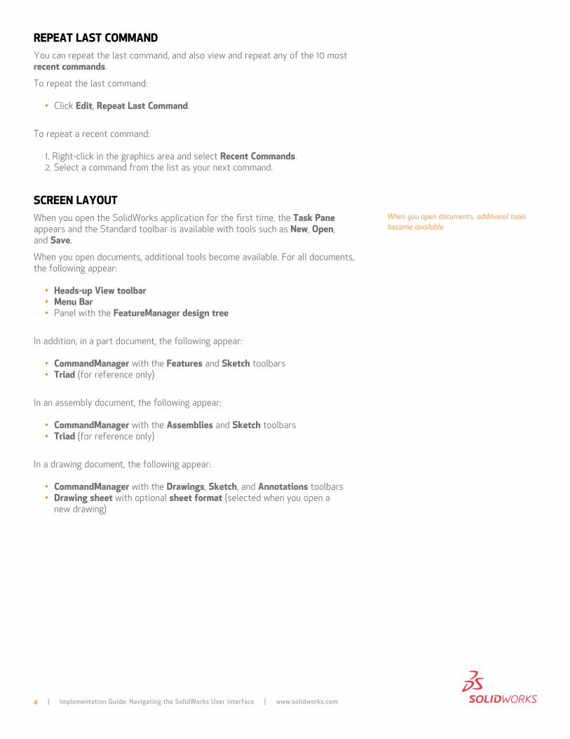
accelerator keys are available for every menu item and are indicated by underlined letters. they cannot be customized.
• to display the underlined letters on the main menu, press Alt.• to access a menu, press Alt plus the underlined letter; for example Alt+F for the
File menu.• to execute a command, press the underlined letter; for example, Alt+F, then c
to close the active document.
keyboard shortcuts are key combinations such as those displayed at the right of the menu, and can be customized.
Undo And RedoYou can undo most recent changes. in sketches within part and assembly documents, you can also redo recent undo commands.
to undo your last action:
• click Undo on the Standard toolbar• click edit, Undo• press ctrl+Z
to redo your last undo action:
• click Redo on the Standard toolbar• click edit, Redo• press ctrl+Y
SolidWorks software keeps a list of available undo and redo actions, so you can choose from the list to undo or redo the selected action and all actions above it.
3 | Implementation Guide: Navigating the SolidWorks User Interface | www.solidworks.com
Customizable shortcut bars let you create your own set of non-context commands
RepeAt lAst coMMAndYou can repeat the last command, and also view and repeat any of the 10 most recent commands.
to repeat the last command:
• click edit, Repeat last command.
to repeat a recent command:
1. right-click in the graphics area and select Recent commands.2. Select a command from the list as your next command.
scReen lAYoUtWhen you open the SolidWorks application for the first time, the task pane appears and the Standard toolbar is available with tools such as new, open, and save.
When you open documents, additional tools become available. for all documents, the following appear:
• Heads-up View toolbar• Menu Bar• panel with the FeatureManager design tree
in addition, in a part document, the following appear:
• commandManager with the Features and sketch toolbars• triad (for reference only)
in an assembly document, the following appear:
• commandManager with the Assemblies and sketch toolbars• triad (for reference only)
in a drawing document, the following appear:
• commandManager with the drawings, sketch, and Annotations toolbars• drawing sheet with optional sheet format (selected when you open a
new drawing)
4 | Implementation Guide: Navigating the SolidWorks User Interface | www.solidworks.com
When you open documents, additional tools become available
to display additional toolbars, right-click an edge of the SolidWorks window and select a toolbar. the toolbar docks to an edge of the window. You can drag toolbars to any edge, or drag them into the graphics area, where they become floating palettes. other modifications you can make to the layout include:
• change the screen background colors.• open a command line.• Set system and document options in tools, options.
When you change the screen layout and options, the changes apply to future SolidWorks sessions.
Some commands are executed immediately, some open dialog boxes, and many open a propertyManager in the Management panel at the left of the graphics area.
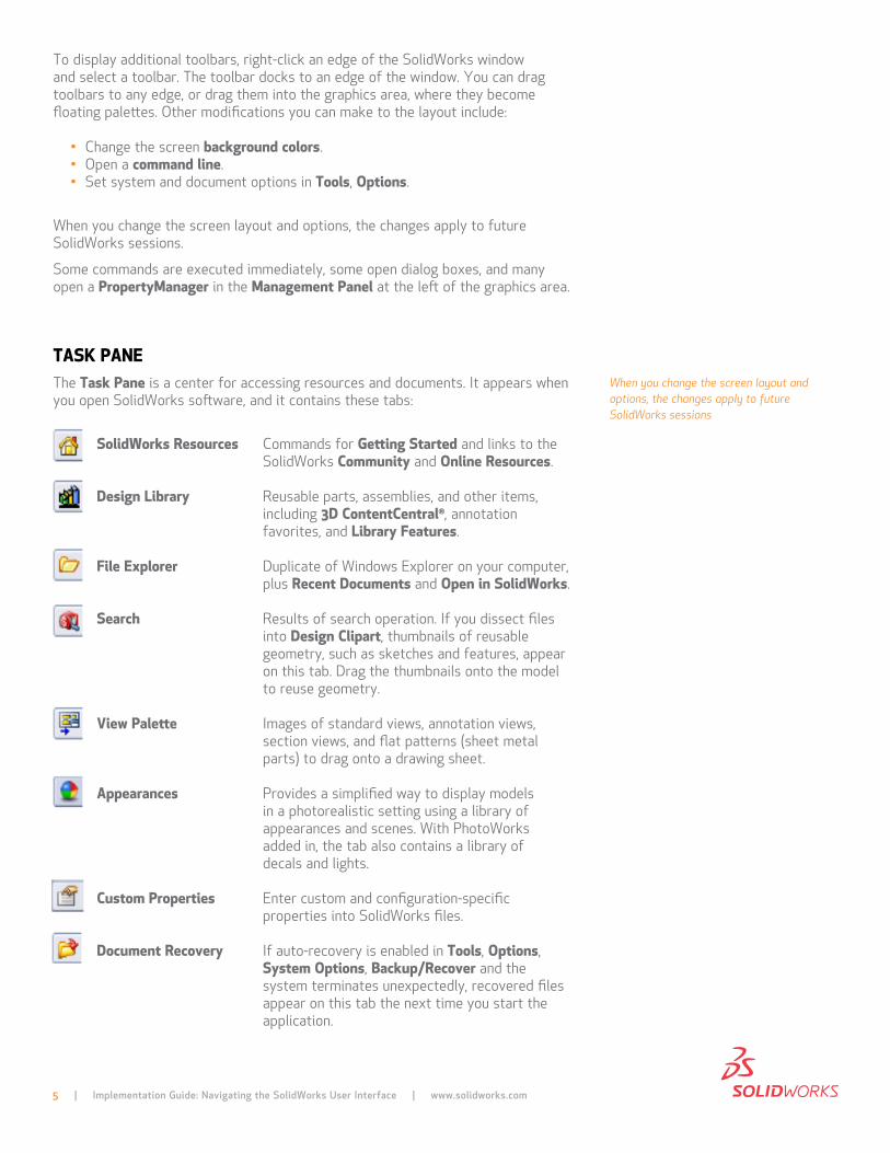
tAsK pAnethe task pane is a center for accessing resources and documents. it appears when you open SolidWorks software, and it contains these tabs:
solidWorks Resources commands for Getting started and links to the SolidWorks community and online Resources.
design library reusable parts, assemblies, and other items, including 3d contentcentral®, annotation favorites, and library Features.
File explorer duplicate of Windows explorer on your computer, plus Recent documents and open in solidWorks.
search results of search operation. if you dissect files into design clipart, thumbnails of reusable geometry, such as sketches and features, appear on this tab. drag the thumbnails onto the model to reuse geometry.
View palette images of standard views, annotation views, section views, and flat patterns (sheet metal parts) to drag onto a drawing sheet.
Appearances provides a simplified way to display models in a photorealistic setting using a library of appearances and scenes. With photoWorks added in, the tab also contains a library of decals and lights.
custom properties enter custom and configuration-specific properties into SolidWorks files.
document Recovery if auto-recovery is enabled in tools, options, system options, Backup/Recover and the system terminates unexpectedly, recovered files appear on this tab the next time you start the application.
5 | Implementation Guide: Navigating the SolidWorks User Interface | www.solidworks.com
When you change the screen layout and options, the changes apply to future SolidWorks sessions
the task pane can be in the following states:
• visible or hidden• expanded or collapsed• pinned or unpinned• docked or floating
You can drag documents from the File explorer tab and the design library tab into the graphics area and from the graphics area or FeatureManager design tree into the design library.
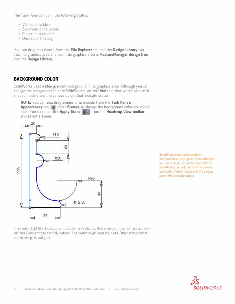
BAcKGRoUnd coloRSolidWorks uses a blue gradient background in its graphics area. although you can change the background color in SolidWorks, you will find that blue works best with shaded models and the various colors that indicate status.
note: You can also drag scenes onto models from the task pane’s Appearances tab, under scenes, to change the background color and model look. You can also click Apply scene from the Heads-up View toolbar and select a scene.
in a sketch, light blue indicates entities that are selected. Blue shows entities that are not fully defined. Black entities are fully defined. the sketch origin appears in red. other status colors are yellow, pink, and gray.
6 | Implementation Guide: Navigating the SolidWorks User Interface | www.solidworks.com
SolidWorks uses a blue gradient background in its graphics area. Although you can change the background color in SolidWorks, you will find that blue works best with shaded models and the various colors that indicate status
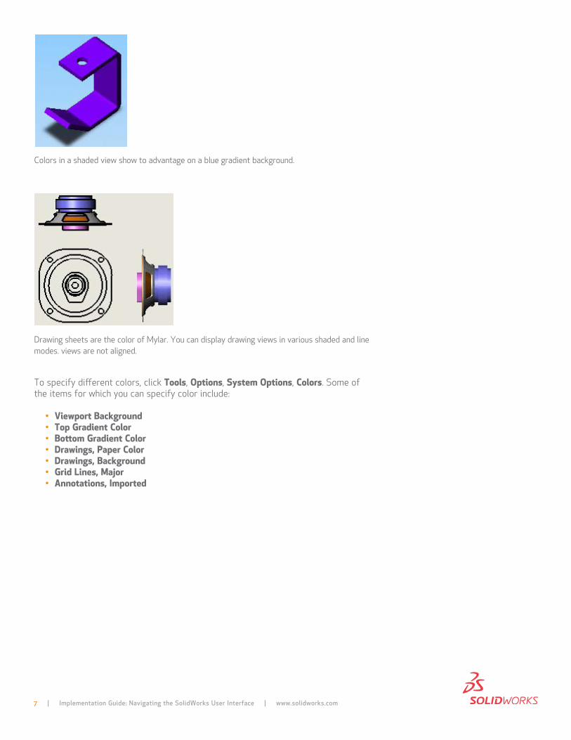
colors in a shaded view show to advantage on a blue gradient background.
drawing sheets are the color of mylar. You can display drawing views in various shaded and line modes. views are not aligned.
to specify different colors, click tools, options, system options, colors. Some of the items for which you can specify color include:
• Viewport Background• top Gradient color• Bottom Gradient color• drawings, paper color• drawings, Background• Grid lines, Major• Annotations, Imported
7 | Implementation Guide: Navigating the SolidWorks User Interface | www.solidworks.com
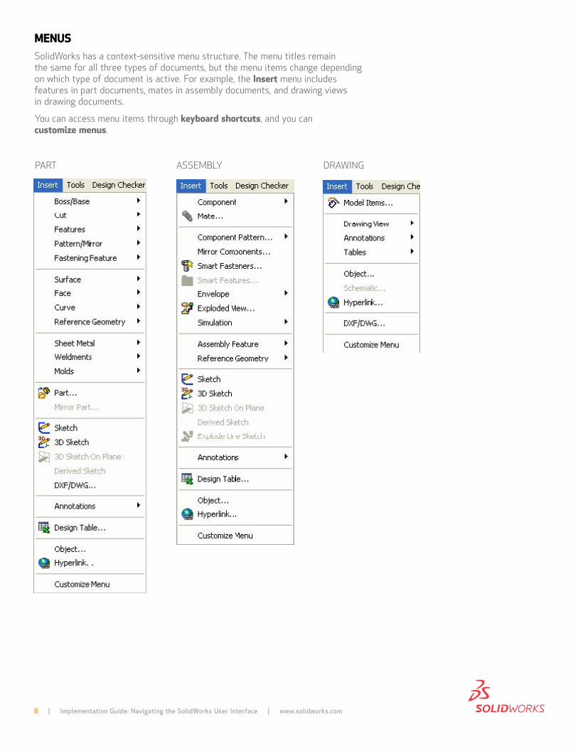
MenUsSolidWorks has a context-sensitive menu structure. the menu titles remain the same for all three types of documents, but the menu items change depending on which type of document is active. for example, the Insert menu includes features in part documents, mates in assembly documents, and drawing views in drawing documents.
You can access menu items through keyboard shortcuts, and you can customize menus.
8 | Implementation Guide: Navigating the SolidWorks User Interface | www.solidworks.com
part aSSemBlY draWing
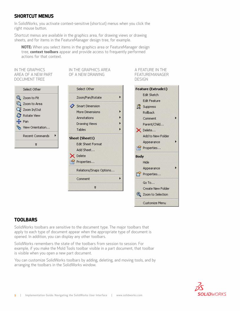
sHoRtcUt MenUsin SolidWorks, you activate context-sensitive (shortcut) menus when you click the right mouse button.
Shortcut menus are available in the graphics area, for drawing views or drawing sheets, and for items in the featuremanager design tree, for example.
note: When you select items in the graphics area or featuremanager design tree, context toolbars appear and provide access to frequently performed actions for that context.
toolBARsSolidWorks toolbars are sensitive to the document type. the major toolbars that apply to each type of document appear when the appropriate type of document is opened. in addition, you can display any other toolbars.
SolidWorks remembers the state of the toolbars from session to session. for example, if you make the mold tools toolbar visible in a part document, that toolbar is visible when you open a new part document.
You can customize SolidWorks toolbars by adding, deleting, and moving tools, and by arranging the toolbars in the SolidWorks window.
9 | Implementation Guide: Navigating the SolidWorks User Interface | www.solidworks.com
in the graphicS area of a neW part document tree
in the graphicS area of a neW draWing
a feature in the featuremanager deSign
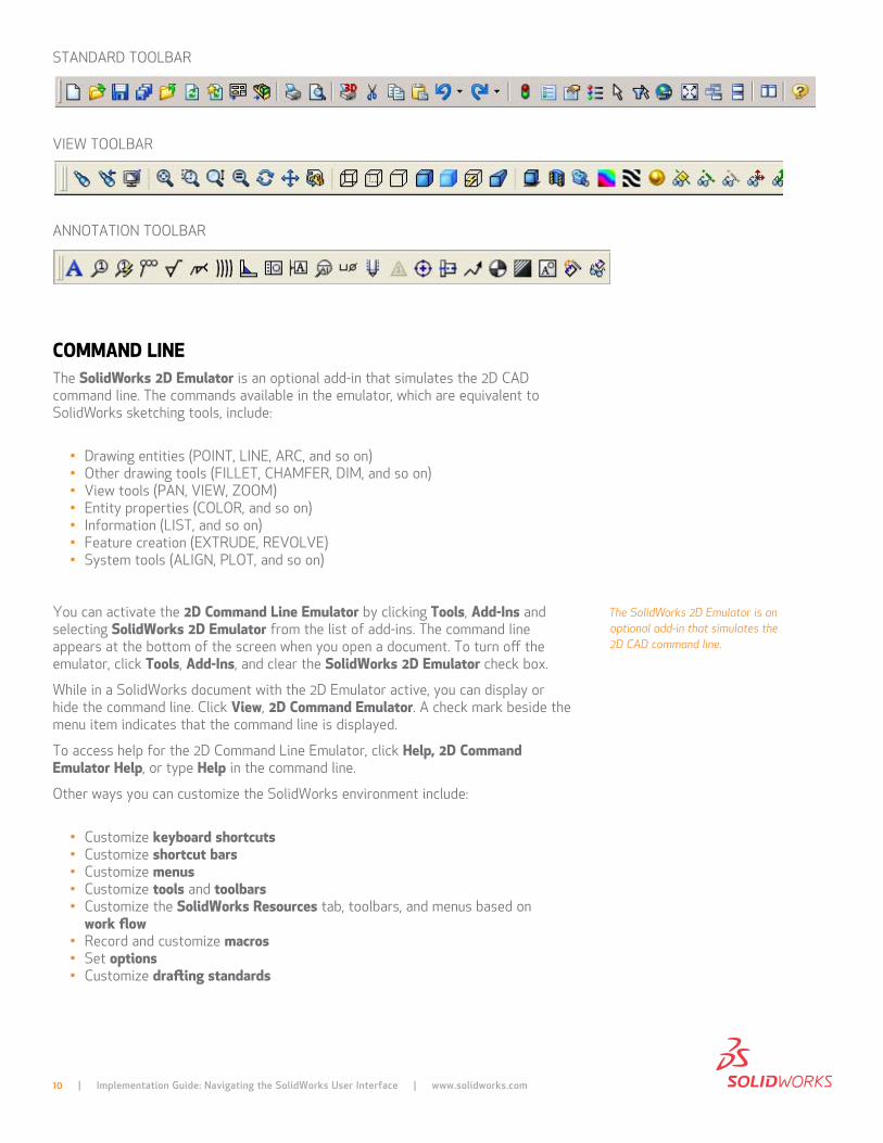
Standard toolBar
vieW toolBar
annotation toolBar
coMMAnd lInethe solidWorks 2d emulator is an optional add-in that simulates the 2d cad command line. the commands available in the emulator, which are equivalent to SolidWorks sketching tools, include:
• drawing entities (point, line, arc, and so on)• other drawing tools (fillet, chamfer, dim, and so on)• view tools (pan, vieW, Zoom)• entity properties (color, and so on)• information (liSt, and so on)• feature creation (eXtrude, revolve)• System tools (align, plot, and so on)
You can activate the 2d command line emulator by clicking tools, Add-Ins and selecting solidWorks 2d emulator from the list of add-ins. the command line appears at the bottom of the screen when you open a document. to turn off the emulator, click tools, Add-Ins, and clear the solidWorks 2d emulator check box.
While in a SolidWorks document with the 2d emulator active, you can display or hide the command line. click View, 2d command emulator. a check mark beside the menu item indicates that the command line is displayed.
to access help for the 2d command line emulator, click Help, 2d command emulator Help, or type Help in the command line.
other ways you can customize the SolidWorks environment include:
• customize keyboard shortcuts• customize shortcut bars• customize menus• customize tools and toolbars• customize the solidWorks Resources tab, toolbars, and menus based on
work flow• record and customize macros• Set options• customize drafting standards
The SolidWorks 2D Emulator is an optional add-in that simulates the 2D CAD command line.
10 | Implementation Guide: Navigating the SolidWorks User Interface | www.solidworks.com
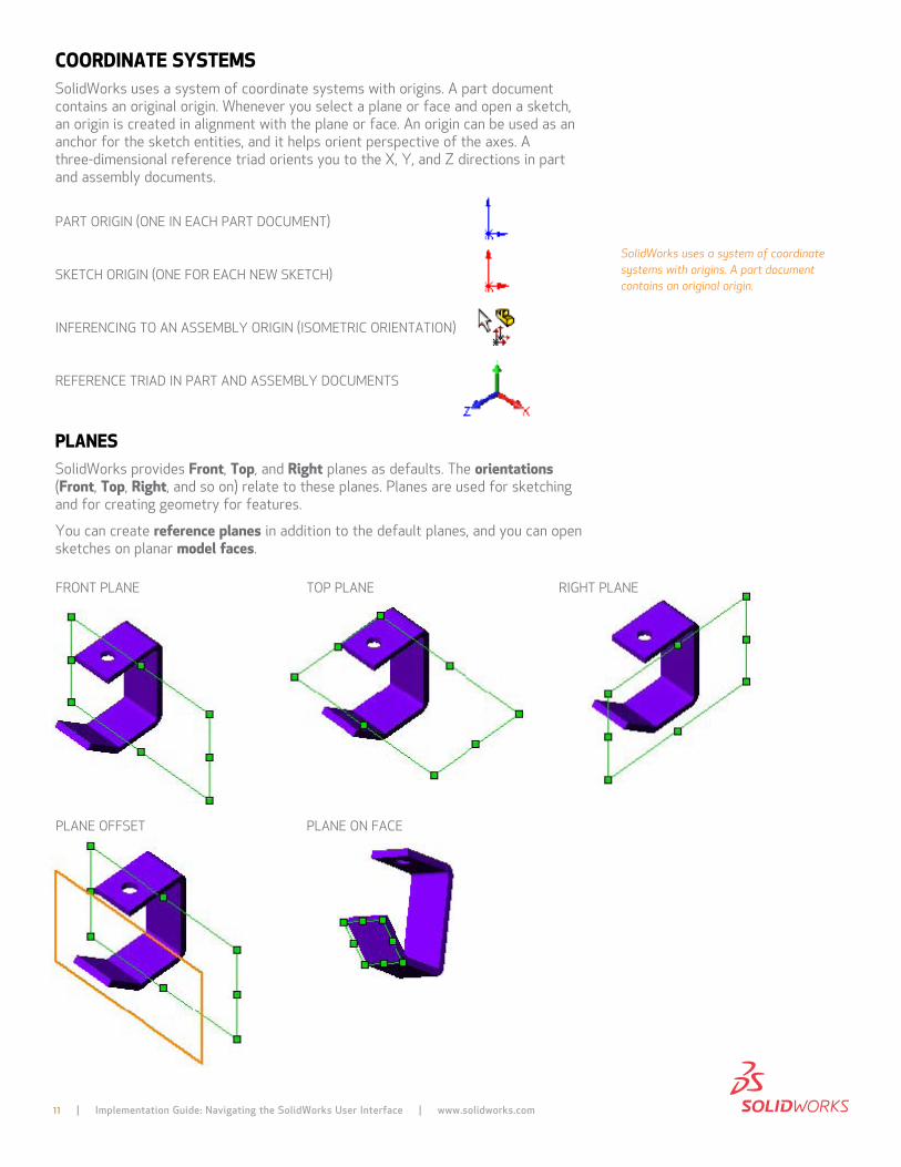
cooRdInAte sYsteMsSolidWorks uses a system of coordinate systems with origins. a part document contains an original origin. Whenever you select a plane or face and open a sketch, an origin is created in alignment with the plane or face. an origin can be used as an anchor for the sketch entities, and it helps orient perspective of the axes. a three-dimensional reference triad orients you to the X, Y, and Z directions in part and assembly documents.
part origin (one in each part document)
Sketch origin (one for each neW Sketch)
inferencing to an aSSemBlY origin (iSometric orientation)
reference triad in part and aSSemBlY documentS
plAnesSolidWorks provides Front, top, and Right planes as defaults. the orientations (Front, top, Right, and so on) relate to these planes. planes are used for sketching and for creating geometry for features.
You can create reference planes in addition to the default planes, and you can open sketches on planar model faces.
11 | Implementation Guide: Navigating the SolidWorks User Interface | www.solidworks.com
front plane
plane offSet
top plane
plane on face
right plane
SolidWorks uses a system of coordinate systems with origins. A part document contains an original origin.
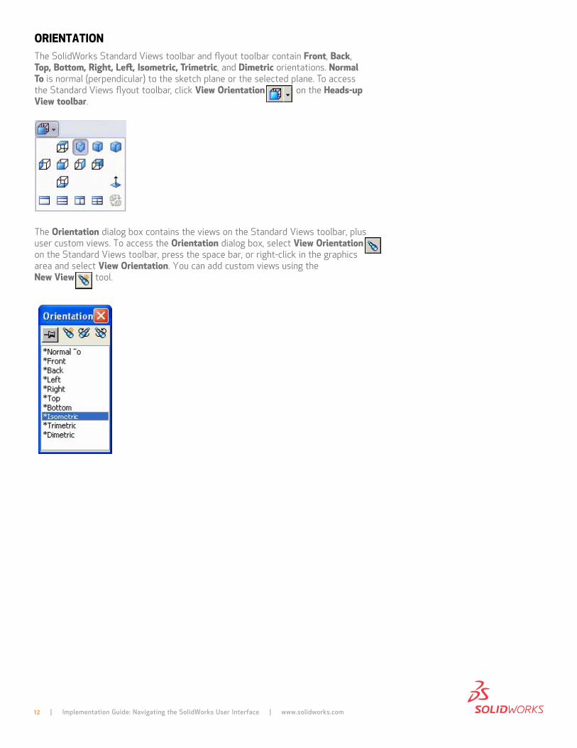
oRIentAtIonthe SolidWorks Standard views toolbar and flyout toolbar contain Front, Back, top, Bottom, Right, left, Isometric, trimetric, and dimetric orientations. normal to is normal (perpendicular) to the sketch plane or the selected plane. to access the Standard views flyout toolbar, click View orientation on the Heads-up View toolbar.
the orientation dialog box contains the views on the Standard views toolbar, plus user custom views. to access the orientation dialog box, select View orientation on the Standard views toolbar, press the space bar, or right-click in the graphics area and select View orientation. You can add custom views using the new View tool.
12 | Implementation Guide: Navigating the SolidWorks User Interface | www.solidworks.com
13 | Implementation Guide: Navigating the SolidWorks User Interface | www.solidworks.com
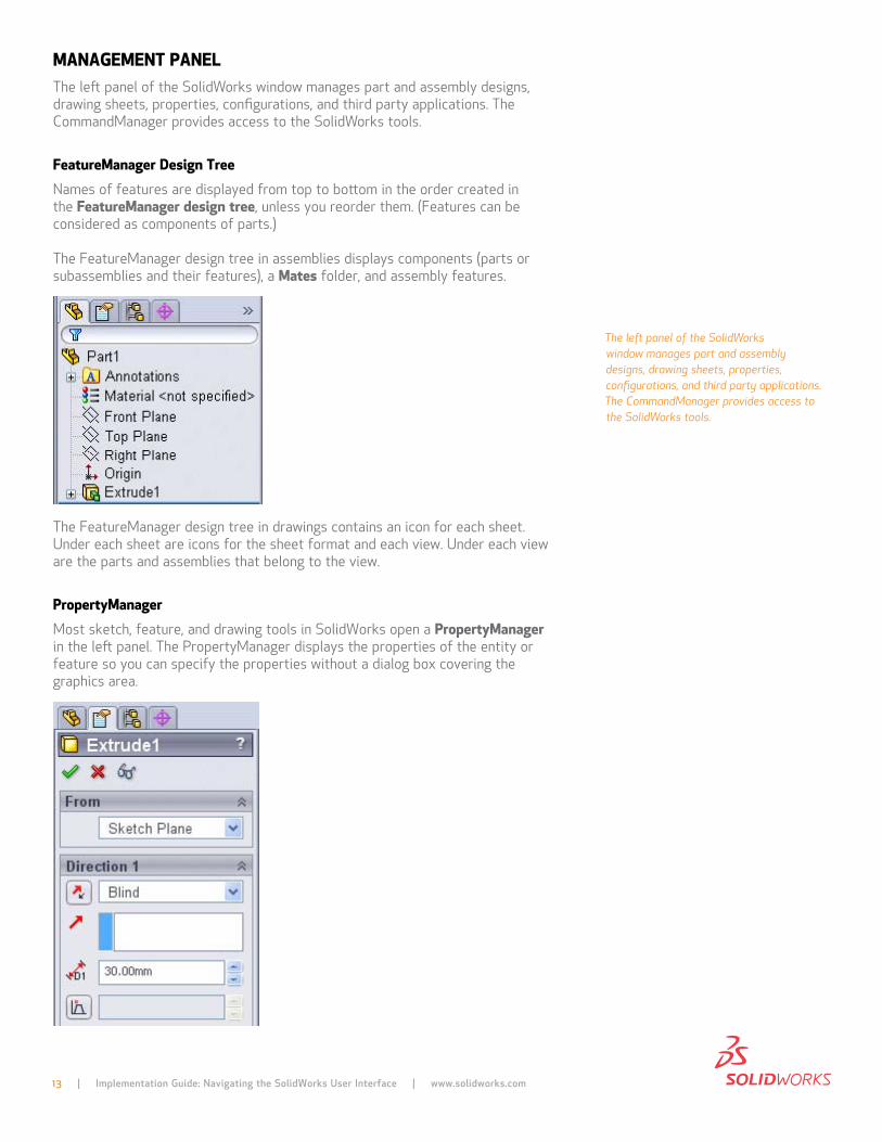
MAnAGeMent pAnelthe left panel of the SolidWorks window manages part and assembly designs, drawing sheets, properties, configurations, and third party applications. the commandmanager provides access to the SolidWorks tools.
FeatureManager design tree names of features are displayed from top to bottom in the order created in the FeatureManager design tree, unless you reorder them. (features can be considered as components of parts.)
the featuremanager design tree in assemblies displays components (parts or subassemblies and their features), a Mates folder, and assembly features.
the featuremanager design tree in drawings contains an icon for each sheet. under each sheet are icons for the sheet format and each view. under each view are the parts and assemblies that belong to the view.
propertyManager most sketch, feature, and drawing tools in SolidWorks open a propertyManager in the left panel. the propertymanager displays the properties of the entity or feature so you can specify the properties without a dialog box covering the graphics area.
The left panel of the SolidWorks window manages part and assembly designs, drawing sheets, properties, configurations, and third party applications. The CommandManager provides access to the SolidWorks tools.
14 | Implementation Guide: Navigating the SolidWorks User Interface | www.solidworks.com
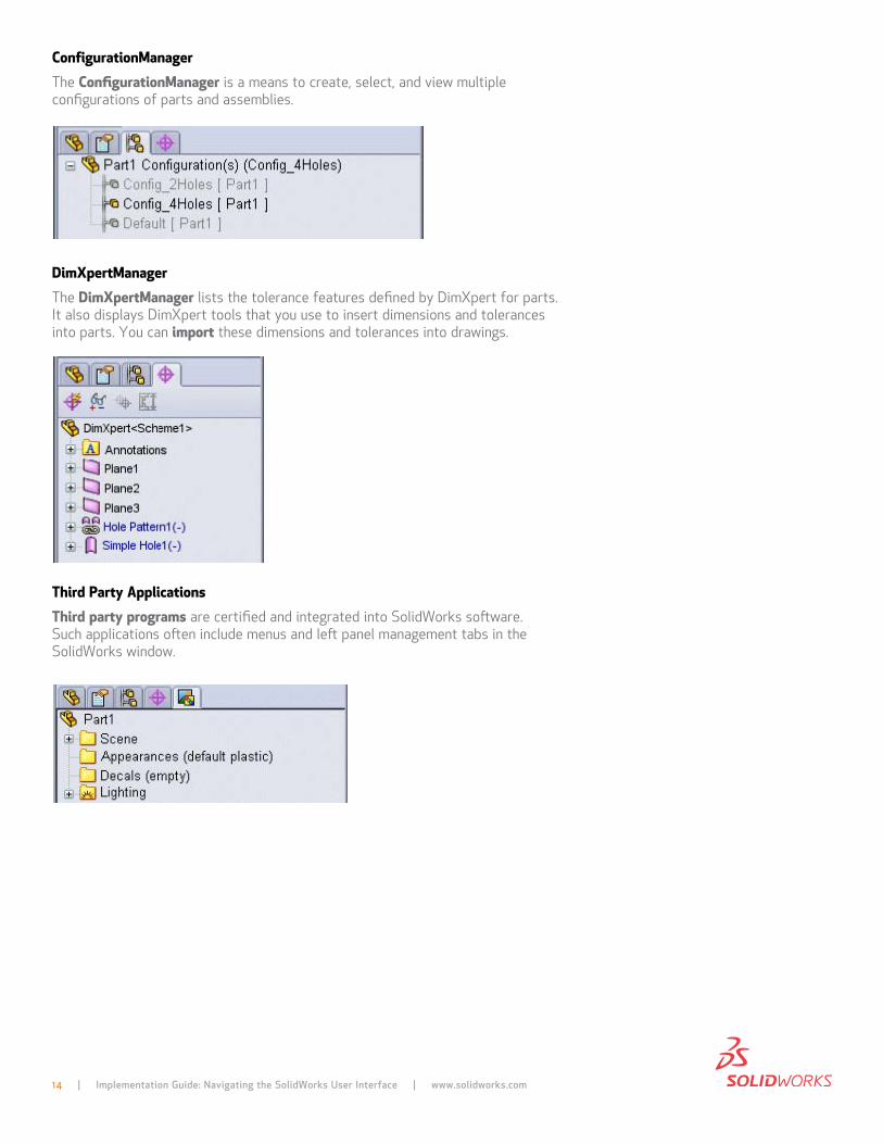
configurationManager the configurationManager is a means to create, select, and view multiple configurations of parts and assemblies.
dimXpertManager the dimXpertManager lists the tolerance features defined by dimXpert for parts. it also displays dimXpert tools that you use to insert dimensions and tolerances into parts. You can import these dimensions and tolerances into drawings.
third party Applications third party programs are certified and integrated into SolidWorks software. Such applications often include menus and left panel management tabs in the SolidWorks window.
15 | Implementation Guide: Navigating the SolidWorks User Interface | www.solidworks.com
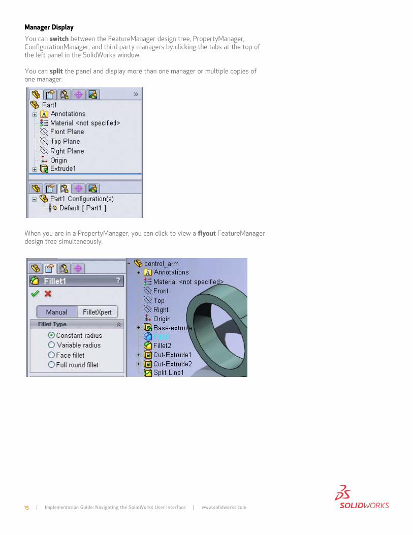
Manager display You can switch between the featuremanager design tree, propertymanager, configurationmanager, and third party managers by clicking the tabs at the top of the left panel in the SolidWorks window.
You can split the panel and display more than one manager or multiple copies of one manager.
When you are in a propertymanager, you can click to view a flyout featuremanager design tree simultaneously.
16 | Implementation Guide: Navigating the SolidWorks User Interface | www.solidworks.com
selectIon MetHodsin SolidWorks, you can select objects as follows:
• click objects in the graphics area• press ctrl while clicking to select more than one object• drag the pointer from left to right to define a box selection or from right to
left to define a cross selection• right-click one entity of a sketch object with multiple entities in a chain (such
as a rectangle or polygon) and choose select chain from the shortcut menu• right-click one edge in a loop of edges in a part and choose select loop for
operations such as feature fillet and chamfer• right-click two edges in a loop of edges in a part and choose select partial
loop to select a series of connecting edges• Select features, components, planes, drawing views, and other items in the
FeatureManager design tree
for many operations, you can select the objects either before or after selecting the tool you want to apply.
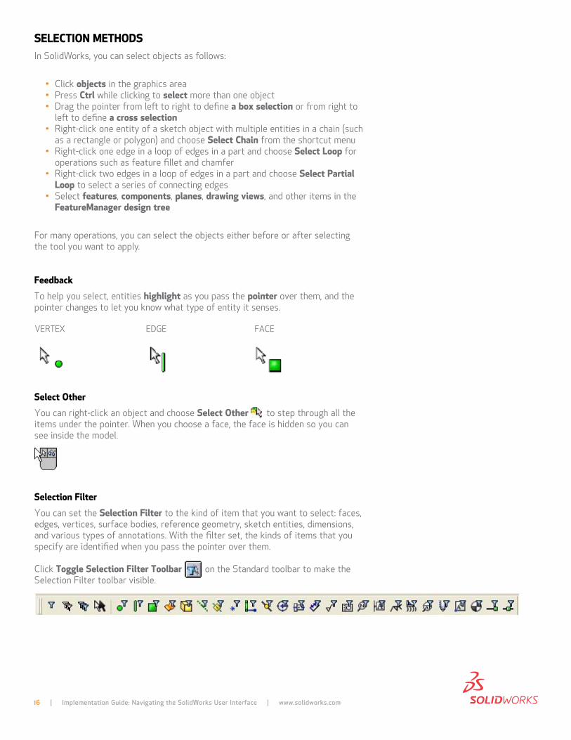
Feedback to help you select, entities highlight as you pass the pointer over them, and the pointer changes to let you know what type of entity it senses.
select other You can right-click an object and choose select other to step through all the items under the pointer. When you choose a face, the face is hidden so you can see inside the model.
selection Filter You can set the selection Filter to the kind of item that you want to select: faces, edges, vertices, surface bodies, reference geometry, sketch entities, dimensions, and various types of annotations. With the filter set, the kinds of items that you specify are identified when you pass the pointer over them.
click toggle selection Filter toolbar on the Standard toolbar to make the Selection filter toolbar visible.
verteX edge face
17 | Implementation Guide: Navigating the SolidWorks User Interface | www.solidworks.com
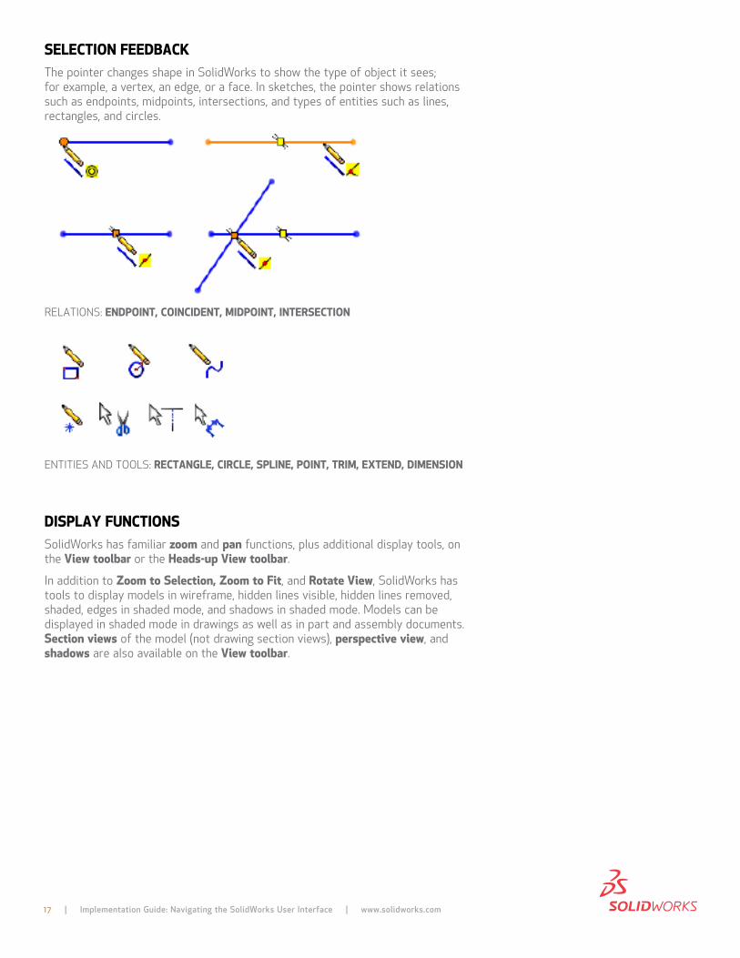
selectIon FeedBAcKthe pointer changes shape in SolidWorks to show the type of object it sees; for example, a vertex, an edge, or a face. in sketches, the pointer shows relations such as endpoints, midpoints, intersections, and types of entities such as lines, rectangles, and circles.
relationS: endpoInt, coIncIdent, MIdpoInt, InteRsectIon
entitieS and toolS: RectAnGle, cIRcle, splIne, poInt, tRIM, eXtend, dIMensIon
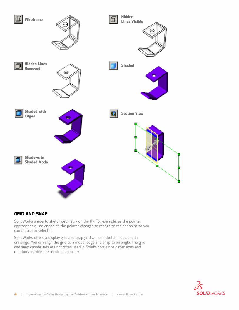
dIsplAY FUnctIonsSolidWorks has familiar zoom and pan functions, plus additional display tools, on the View toolbar or the Heads-up View toolbar.
in addition to Zoom to selection, Zoom to Fit, and Rotate View, SolidWorks has tools to display models in wireframe, hidden lines visible, hidden lines removed, shaded, edges in shaded mode, and shadows in shaded mode. models can be displayed in shaded mode in drawings as well as in part and assembly documents. section views of the model (not drawing section views), perspective view, and shadows are also available on the View toolbar.
18 | Implementation Guide: Navigating the SolidWorks User Interface | www.solidworks.com
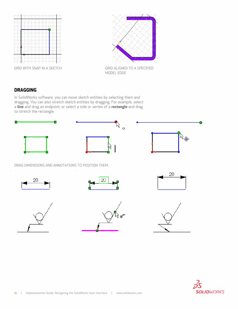
GRId And snApSolidWorks snaps to sketch geometry on the fly. for example, as the pointer approaches a line endpoint, the pointer changes to recognize the endpoint so you can choose to select it.
SolidWorks offers a display grid and snap grid while in sketch mode and in drawings. You can align the grid to a model edge and snap to an angle. the grid and snap capabilities are not often used in SolidWorks since dimensions and relations provide the required accuracy.
WireframeHidden lines Visible
Hidden lines Removed
shaded
shaded with edges
section View
shadows in shaded Mode
19 | Implementation Guide: Navigating the SolidWorks User Interface | www.solidworks.com
dRAGGInGin SolidWorks software, you can move sketch entities by selecting them and dragging. You can also stretch sketch entities by dragging. for example, select a line and drag an endpoint, or select a side or vertex of a rectangle and drag to stretch the rectangle.
drag dimenSionS and annotationS to poSition them.
grid With Snap in a Sketch grid aligned to a Specified model edge
20 | Implementation Guide: Navigating the SolidWorks User Interface | www.solidworks.com
You can also drag drawing views.
to drag drawing views:
• Select a view (the pointer changes to ) and press Alt while dragging. - or -• Select the edge of a view (the pointer changes to ), then drag.
many other items are available for dragging, including feature previews, components in assemblies, and so on.
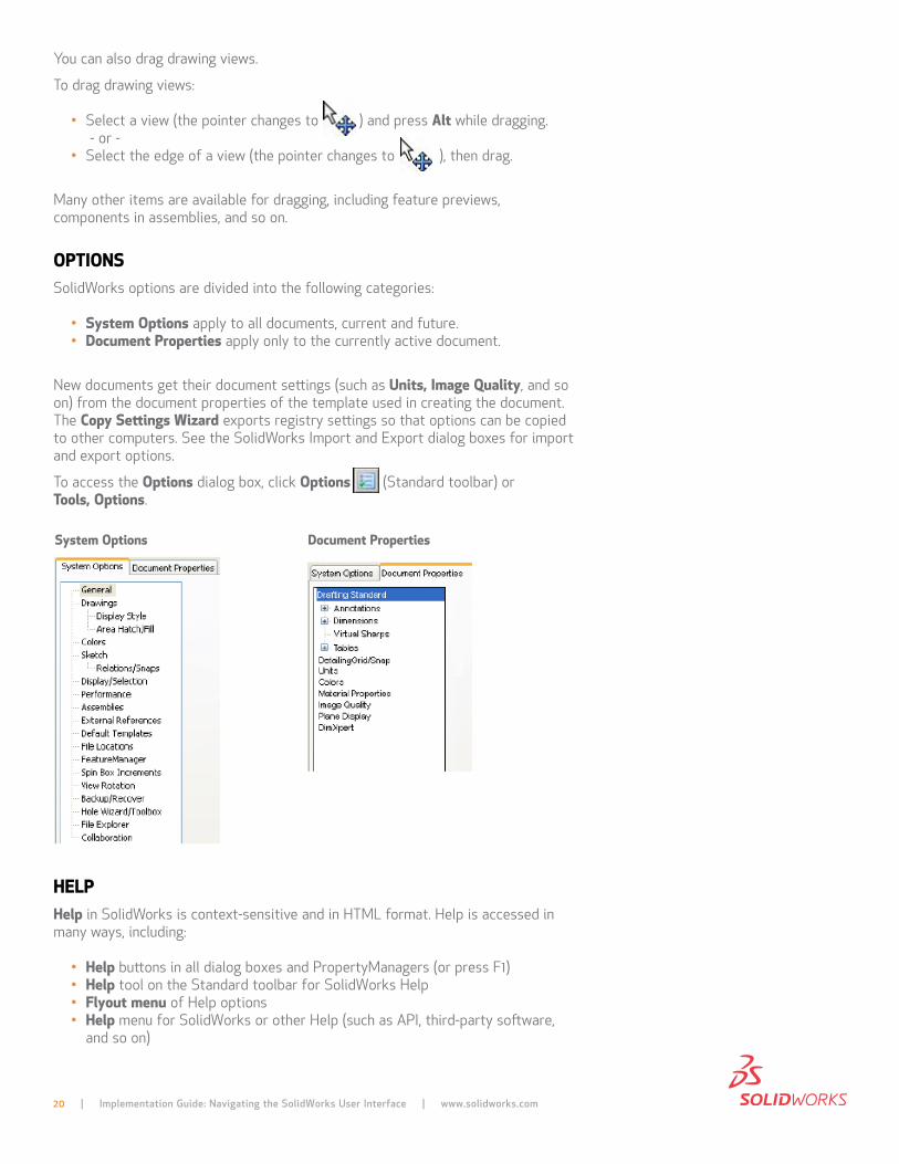
optIonsSolidWorks options are divided into the following categories:
• system options apply to all documents, current and future.• document properties apply only to the currently active document.
new documents get their document settings (such as Units, Image Quality, and so on) from the document properties of the template used in creating the document. the copy settings Wizard exports registry settings so that options can be copied to other computers. See the SolidWorks import and export dialog boxes for import and export options.
to access the options dialog box, click options (Standard toolbar) or tools, options.
HelpHelp in SolidWorks is context-sensitive and in html format. help is accessed in many ways, including:
• Help buttons in all dialog boxes and propertymanagers (or press f1)• Help tool on the Standard toolbar for SolidWorks help• Flyout menu of help options• Help menu for SolidWorks or other help (such as api, third-party software,
and so on)
system options document properties
Glossary. SolidWorks help contains a glossary of terms. click Glossary at the bottom of the table of contents.
in addition to the help facility, SolidWorks provides help in the following ways:
• What’s new (on the Help menu)—new functionality added since the last major SolidWorks release
• Interactive What’s new (click in new menus and new or changed propertymanagers)—links to topics in the What’s new book.
• Quick tips (click on the status bar)—pop-up messages that give hints and options based on the current SolidWorks mode.
• tooltips—information about tools on toolbars and in propertymanagers and dialog boxes.
• Status bar information (at the bottom of the SolidWorks window)—pointer coordinates, sketch status, and brief descriptions of selected commands.
• tip of the day (at the bottom of the solidWorks Resources tab in the task pane)—a new tip appears each time you start SolidWorks.
• solidWorks tutorials (on the help menu and on the SolidWorks resources tab in the task pane)—step-by-step lessons on features, parts, assemblies, drawings, and third-party applications.
• solidWorks Resources tab in the task pane includes commands, links, and information. the General Information link provides access to documentation central. documentation central is the reference library for beginning and advanced users. documentation central features tutorials and simulations, an interactive environment for collaborative development, access to published manuals and updates, and late-breaking and experimental documentation.
through customizable, interactive menus and smart pointers, your team can quickly and conveniently navigate the SolidWorks environment. With SolidWorks on your team, the user interface works for you so you can design products easily.
additional ideas and help are available on the SolidWorks web site at www.solidworks.com.
SolidWorks is a registered trademark of dassault Systèmes SolidWorks corp. all other company and product names are trademarks or registered trademarks of their respective owners. ©2011 dassault Systèmes. all rights reserved. mkuSerinttpeng0611
dassault Systèmes SolidWorks corp. 300 Baker avenue concord, ma 01742 uSa phone: 1 800 693 9000 outside the uS: +1 978 371 5011 email: [email protected] www.solidworks.com