IIC Module S08 - NXP Semiconductors · The IIC module on the S08 reduces software overhead by...
24
Course Introduction Purpose • The intent of this course is to explain how to configure the IIC module for the 9S08 MCU. Objectives • Describe the features and applications of the IIC module. • Identify the various IIC registers. • Describe the IIC protocol. • List the steps for IIC Master and Slave initialization. Content • 21 pages • 3 questions Learning Time • 35 minutes The goal of this course is to explain how to configure the inter-integrated circuit (IIC) module for the 9S08 MCU. To begin, you will examine the features and typical applications of the IIC module. Next, you will learn to identify the IIC registers and describe the IIC protocol. Finally you will learn the steps for IIC Master and Slave initialization. You will look at an Interrupt Service Routine (ISR) flowchart to help you understand the variables that must be set to implement the ISR.
Transcript of IIC Module S08 - NXP Semiconductors · The IIC module on the S08 reduces software overhead by...
1
Course Introduction
Purpose • The intent of this course is to explain how to configure the IIC module for
the 9S08 MCU.
Objectives • Describe the features and applications of the IIC module.• Identify the various IIC registers.• Describe the IIC protocol.• List the steps for IIC Master and Slave initialization.
Content• 21 pages• 3 questions
Learning Time• 35 minutes
The goal of this course is to explain how to configure the inter-integrated circuit (IIC) module for the 9S08 MCU.
To begin, you will examine the features and typical applications of the IIC module. Next, you will learn to identify the IIC registers and describe the IIC protocol. Finally you will learn the steps for IIC Master and Slave initialization. You will look at an Interrupt Service Routine (ISR) flowchart to help you understand the variables that must be set to implement the ISR.
2
IIC Features• Compatible with IIC bus standard• Multimaster operation• Software programmable for one of 64 different serial clock frequencies• Interrupt-driven byte-by-byte data transfer• Arbitration lost interrupt with automatic mode switching from master to slave• START and STOP signal generation/detection• Address identification interrupt• Repeated START sequences• Acknowledge bit generation/detection• Bus busy detection
Let’s begin with a look at the features of the IIC. The IIC provides a method of communication between a number of devices on the same bus. This interface operates up to 100 Kbps with maximum bus loading and timing. The device is capable of operating at higher baud rates, up to a maximum of the IIC reference clock/20, with reduced bus loading. The maximum bus capacitance of 400 pF limits the maximum communication length and the number of devices that can be connected.
The S08 IIC is compatible with IIC bus industry standards. This peripheral was built to handle multimaster operations; therefore, arbitration can be done.
The IIC frequency divide register provides a great deal of flexibility when configuring the IIC baud rate. Sixty-four different serial clock frequencies can be configured.
Another important feature of the IIC module is that it implements interrupt-driven byte-by-byte transfer. This allows the ISR to handle IIC communication.
Arbitration lost interrupt allows automatic mode switching from master to slave. This important feature detects whether a different master has control of the bus, and it allows an ISR to deal with multimaster operations. Note that all IIC interrupts are directed to the same vector.
The IIC module on the S08 reduces software overhead by performing START and STOP signal generation/detection, addressed identification interrupt, and repeated START sequences.
Finally, features like acknowledge bit generation and detection, as well as bus busy detection, allow easy implementation of an IIC software solution.
3
IIC Applications
• It is easy to add more devices to the bus.
• SCL and SDA provide a simple 2 line interface.
IIC Applications
EEPROMs
Temperature Sensors Other MCUs
A/D and D/A Chips
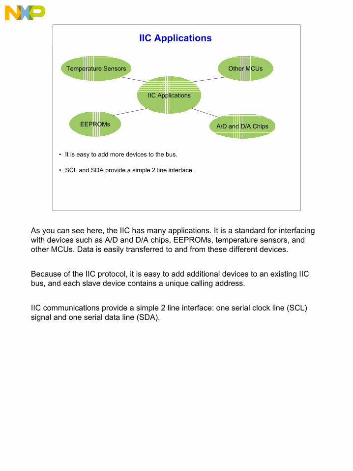
As you can see here, the IIC has many applications. It is a standard for interfacing with devices such as A/D and D/A chips, EEPROMs, temperature sensors, and other MCUs. Data is easily transferred to and from these different devices.
Because of the IIC protocol, it is easy to add additional devices to an existing IIC bus, and each slave device contains a unique calling address.
IIC communications provide a simple 2 line interface: one serial clock line (SCL) signal and one serial data line (SDA).
4
IIC Block Diagram
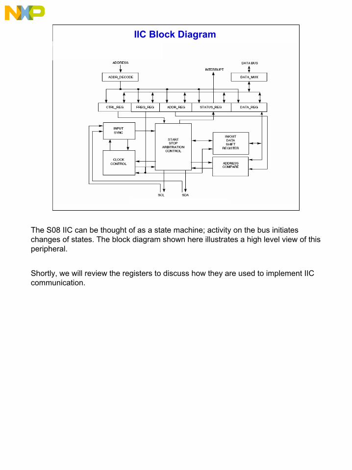
The S08 IIC can be thought of as a state machine; activity on the bus initiates changes of states. The block diagram shown here illustrates a high level view of this peripheral.
Shortly, we will review the registers to discuss how they are used to implement IIC communication.
5
QuestionIs the following statement true or false? Click Done when you are finished.
“The IIC module can configure 64 different serial clock frequencies.”
True
False
Consider this question concerning features of the IIC module.
Correct.
The IIC module can configure 64 different serial clock frequencies.
6
IIC Address Register
IICA
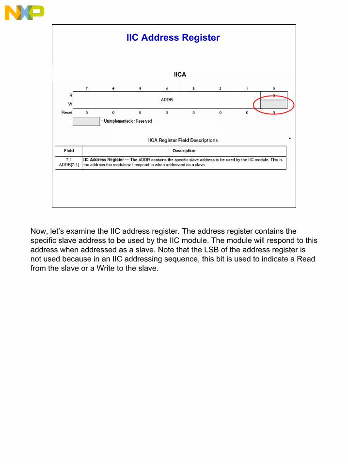
Now, let’s examine the IIC address register. The address register contains the specific slave address to be used by the IIC module. The module will respond to this address when addressed as a slave. Note that the LSB of the address register is not used because in an IIC addressing sequence, this bit is used to indicate a Read from the slave or a Write to the slave.
7
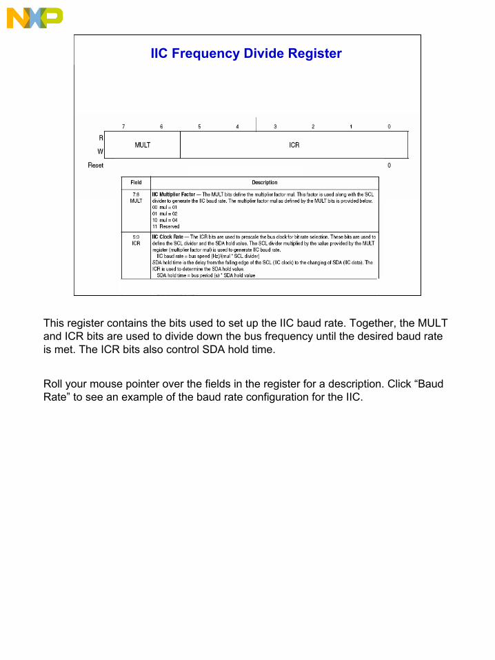
IIC Frequency Divide Register
This register contains the bits used to set up the IIC baud rate. Together, the MULT and ICR bits are used to divide down the bus frequency until the desired baud rate is met. The ICR bits also control SDA hold time.
Roll your mouse pointer over the fields in the register for a description. Click “Baud Rate” to see an example of the baud rate configuration for the IIC.
8
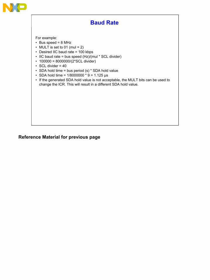
Baud Rate
For example:• Bus speed = 8 MHz• MULT is set to 01 (mul = 2)• Desired IIC baud rate = 100 kbps• IIC baud rate = bus speed (Hz)/(mul * SCL divider)• 100000 = 8000000/(2*SCL divider)• SCL divider = 40• SDA hold time = bus period (s) * SDA hold value• SDA hold time = 1/8000000 * 9 = 1.125 µs• If the generated SDA hold value is not acceptable, the MULT bits can be used to
change the ICR. This will result in a different SDA hold value.
Reference Material for previous page
9
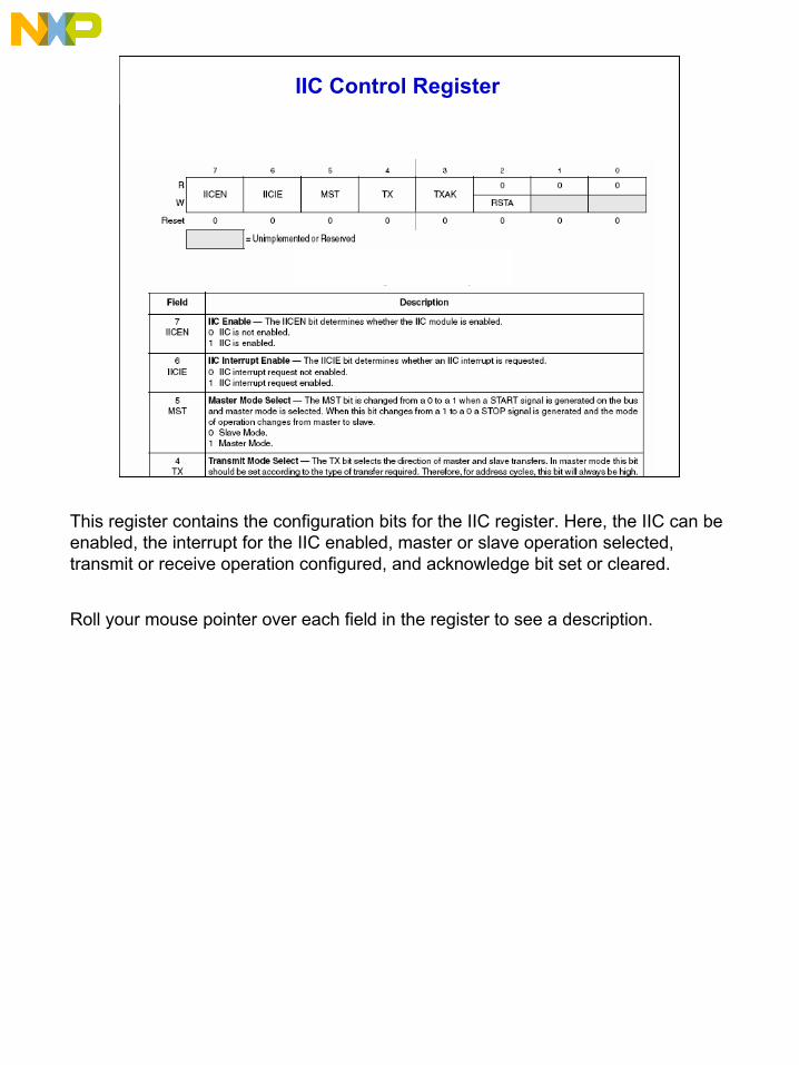
IIC Control Register
This register contains the configuration bits for the IIC register. Here, the IIC can be enabled, the interrupt for the IIC enabled, master or slave operation selected, transmit or receive operation configured, and acknowledge bit set or cleared.
Roll your mouse pointer over each field in the register to see a description.
10
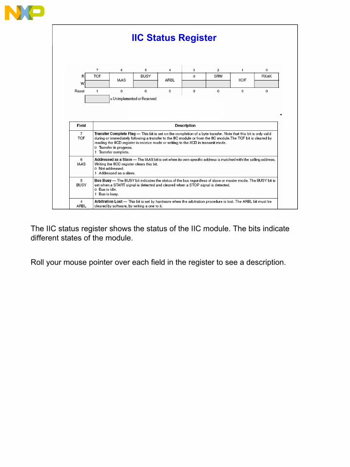
IIC Status Register
The IIC status register shows the status of the IIC module. The bits indicate different states of the module.
Roll your mouse pointer over each field in the register to see a description.
11
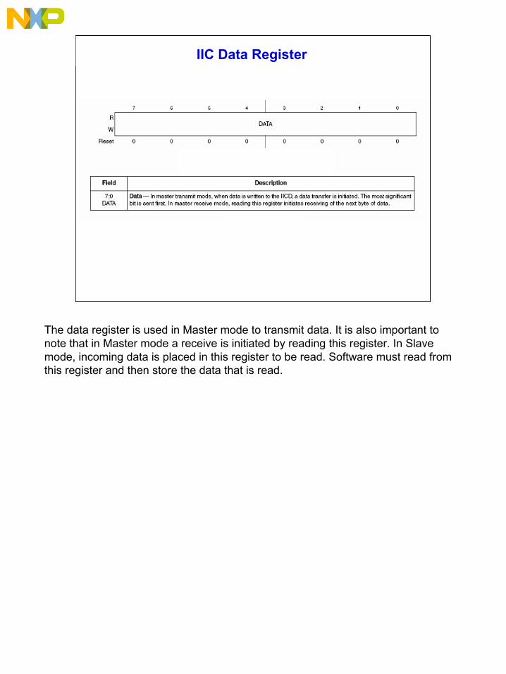
IIC Data Register
The data register is used in Master mode to transmit data. It is also important to note that in Master mode a receive is initiated by reading this register. In Slave mode, incoming data is placed in this register to be read. Software must read from this register and then store the data that is read.
12
B
C
Done Reset ShowSolution
A
C
E
QuestionCan you remember the different IIC registers? Match each IIC register on
the left with its description on the right. Click “Done” when you are finished.
AD
BIIC address register
IIC frequency divide register
IIC control register
IIC status register
IIC data registerE D
This register contains the bits used to set up the IIC baud rate.
This register is used in Master mode to transmit and receive data.This register contains the configuration bits for the IIC register.
This register contains the specific slave address to be used by the IIC module.
This register is used to show the status of the IIC module.
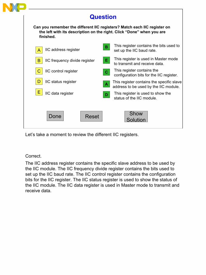
Let’s take a moment to review the different IIC registers.
Correct. The IIC address register contains the specific slave address to be used by the IIC module. The IIC frequency divide register contains the bits used to set up the IIC baud rate. The IIC control register contains the configuration bits for the IIC register. The IIC status register is used to show the status of the IIC module. The IIC data register is used in Master mode to transmit and receive data.
13
IIC Protocol
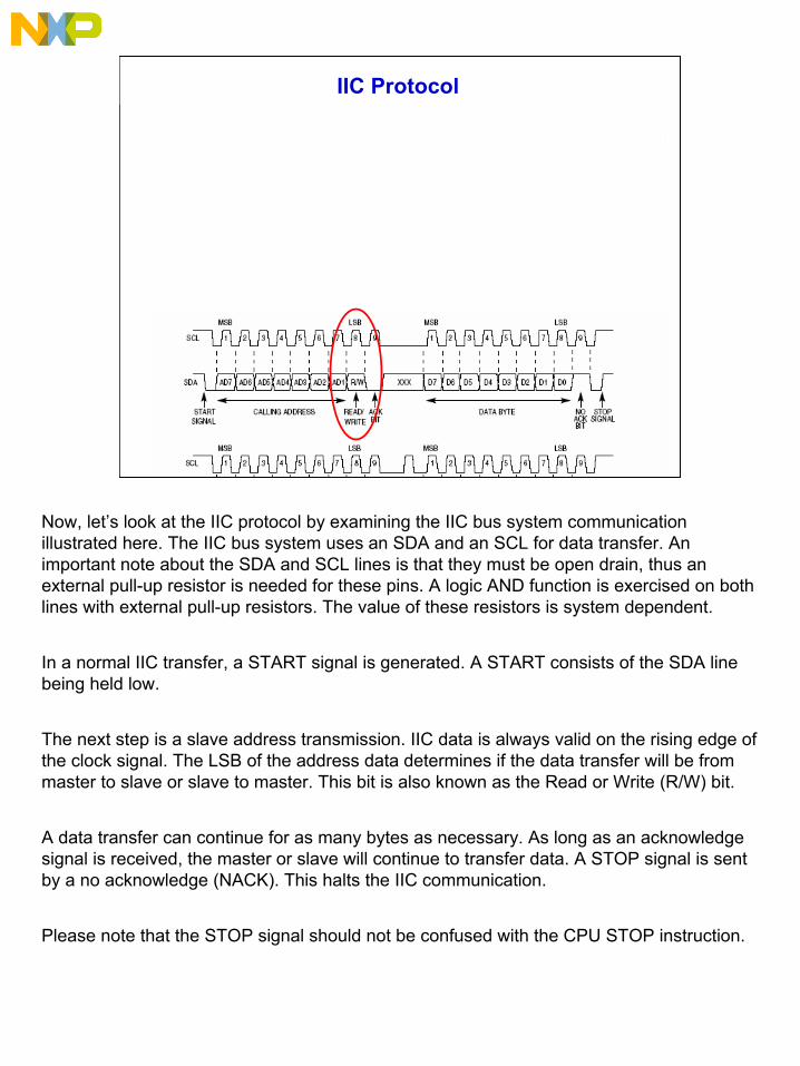
Now, let’s look at the IIC protocol by examining the IIC bus system communication illustrated here. The IIC bus system uses an SDA and an SCL for data transfer. An important note about the SDA and SCL lines is that they must be open drain, thus an external pull-up resistor is needed for these pins. A logic AND function is exercised on both lines with external pull-up resistors. The value of these resistors is system dependent.
In a normal IIC transfer, a START signal is generated. A START consists of the SDA line being held low.
The next step is a slave address transmission. IIC data is always valid on the rising edge of the clock signal. The LSB of the address data determines if the data transfer will be from master to slave or slave to master. This bit is also known as the Read or Write (R/W) bit.
A data transfer can continue for as many bytes as necessary. As long as an acknowledge signal is received, the master or slave will continue to transfer data. A STOP signal is sent by a no acknowledge (NACK). This halts the IIC communication.
Please note that the STOP signal should not be confused with the CPU STOP instruction.
14
Slave Initialization
1. Write IIC address register to set the slave address.
2. Write control register to enable IIC and interrupts (IICEN and IICIE bits are set).
3. Initialize RAM variables to be used to transmit data.
4. Initialize variables to be used to achieve the flowchart
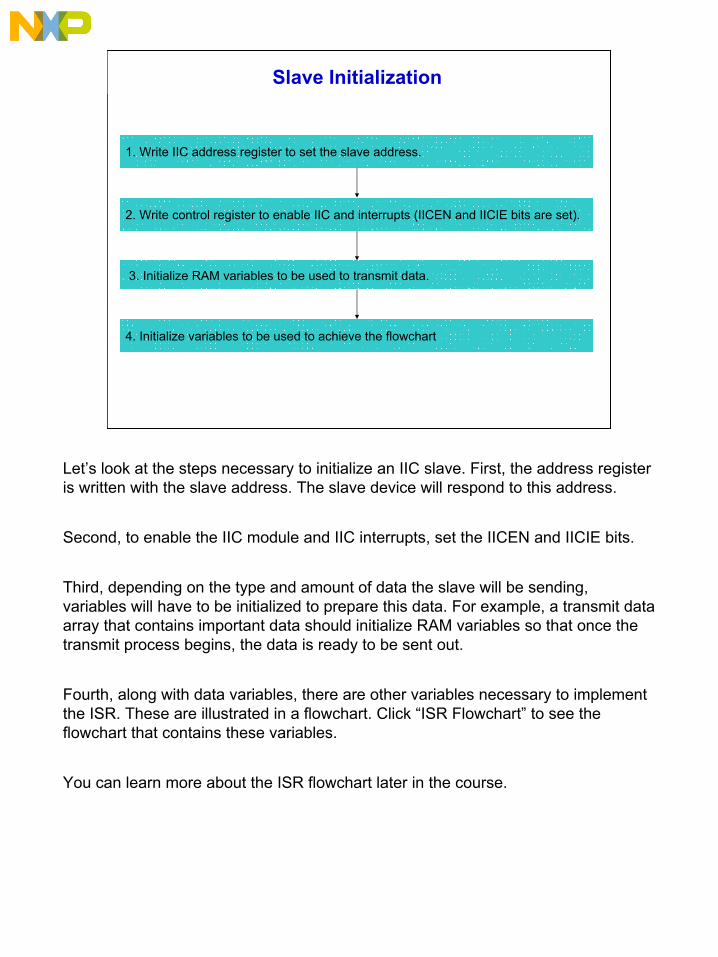
Let’s look at the steps necessary to initialize an IIC slave. First, the address register is written with the slave address. The slave device will respond to this address.
Second, to enable the IIC module and IIC interrupts, set the IICEN and IICIE bits.
Third, depending on the type and amount of data the slave will be sending, variables will have to be initialized to prepare this data. For example, a transmit data array that contains important data should initialize RAM variables so that once the transmit process begins, the data is ready to be sent out.
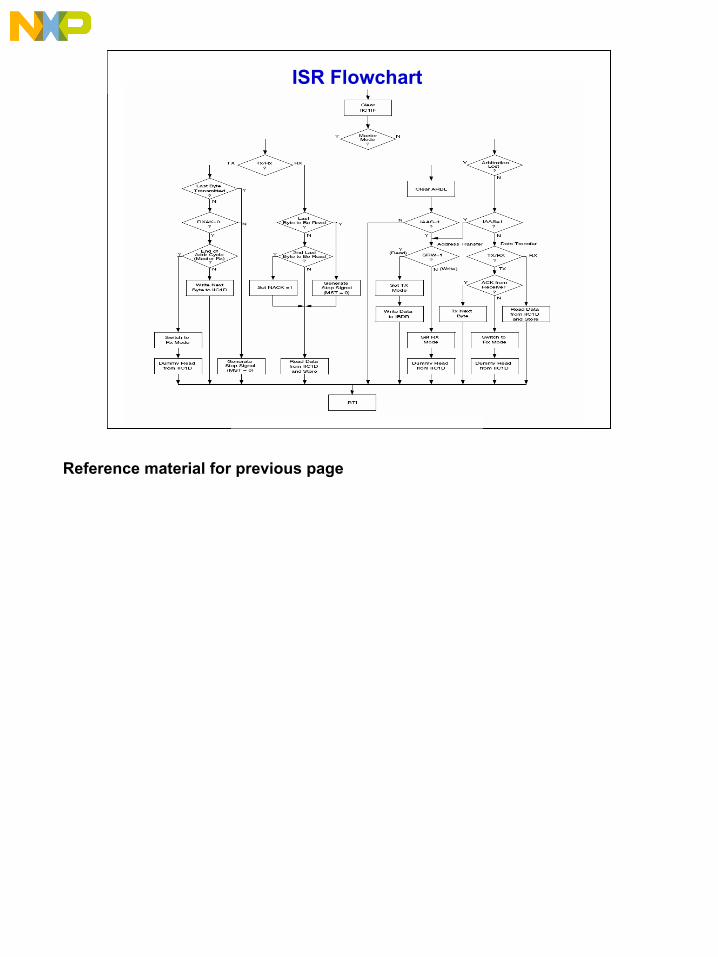
Fourth, along with data variables, there are other variables necessary to implement the ISR. These are illustrated in a flowchart. Click “ISR Flowchart” to see the flowchart that contains these variables.
You can learn more about the ISR flowchart later in the course.
15
ISR Flowchart
Reference material for previous page
16
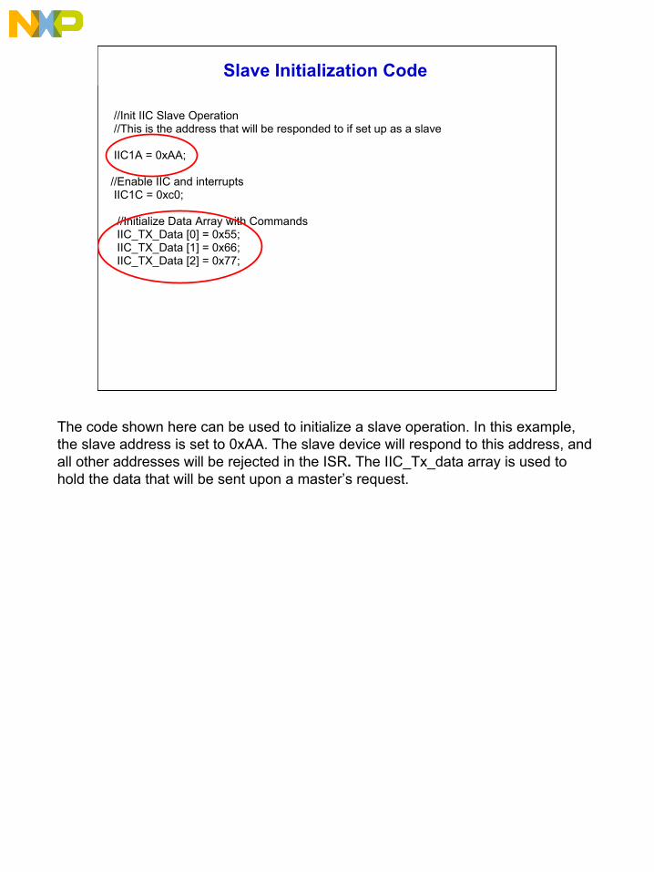
Slave Initialization Code
//Init IIC Slave Operation//This is the address that will be responded to if set up as a slave
IIC1A = 0xAA;
//Enable IIC and interrupts IIC1C = 0xc0;
//Initialize Data Array with CommandsIIC_TX_Data [0] = 0x55;IIC_TX_Data [1] = 0x66;IIC_TX_Data [2] = 0x77;
The code shown here can be used to initialize a slave operation. In this example, the slave address is set to 0xAA. The slave device will respond to this address, and all other addresses will be rejected in the ISR. The IIC_Tx_data array is used to hold the data that will be sent upon a master’s request.
17
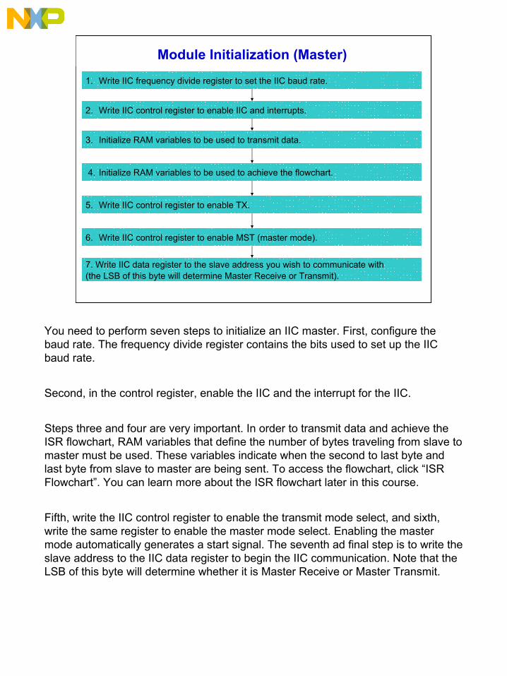
Module Initialization (Master)
1. Write IIC frequency divide register to set the IIC baud rate.
2. Write IIC control register to enable IIC and interrupts.
3. Initialize RAM variables to be used to transmit data.
4. Initialize RAM variables to be used to achieve the flowchart.
5. Write IIC control register to enable TX.
7. Write IIC data register to the slave address you wish to communicate with (the LSB of this byte will determine Master Receive or Transmit).
6. Write IIC control register to enable MST (master mode).
You need to perform seven steps to initialize an IIC master. First, configure the baud rate. The frequency divide register contains the bits used to set up the IIC baud rate.
Second, in the control register, enable the IIC and the interrupt for the IIC.
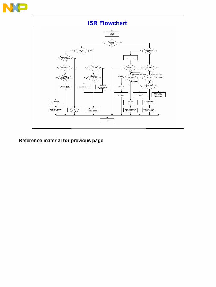
Steps three and four are very important. In order to transmit data and achieve the ISR flowchart, RAM variables that define the number of bytes traveling from slave to master must be used. These variables indicate when the second to last byte and last byte from slave to master are being sent. To access the flowchart, click “ISR Flowchart”. You can learn more about the ISR flowchart later in this course.
Fifth, write the IIC control register to enable the transmit mode select, and sixth, write the same register to enable the master mode select. Enabling the master mode automatically generates a start signal. The seventh ad final step is to write the slave address to the IIC data register to begin the IIC communication. Note that the LSB of this byte will determine whether it is Master Receive or Master Transmit.
18
ISR Flowchart
Reference material for previous page
19
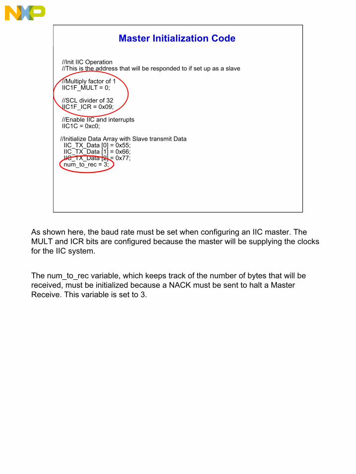
Master Initialization Code
//Init IIC Operation//This is the address that will be responded to if set up as a slave
//Multiply factor of 1IIC1F_MULT = 0;
//SCL divider of 32IIC1F_ICR = 0x09;
//Enable IIC and interrupts IIC1C = 0xc0;
//Initialize Data Array with Slave transmit DataIIC_TX_Data [0] = 0x55;IIC_TX_Data [1] = 0x66;IIC_TX_Data [2] = 0x77;num_to_rec = 3;
As shown here, the baud rate must be set when configuring an IIC master. The MULT and ICR bits are configured because the master will be supplying the clocks for the IIC system.
The num_to_rec variable, which keeps track of the number of bytes that will bereceived, must be initialized because a NACK must be sent to halt a Master Receive. This variable is set to 3.
20
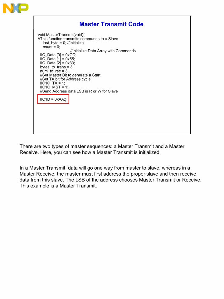
Master Transmit Codevoid MasterTransmit(void){//This function transmits commands to a Slave
last_byte = 0; //Initialize count = 0;
//Initialize Data Array with CommandsIIC_Data [0] = 0xCC;IIC_Data [1] = 0x55;IIC_Data [2] = 0x33;bytes_to_trans = 3;num_to_rec = 3;//Set Master Bit to generate a Start//Set TX bit for Address cycleIIC1C_TX = 1;IIC1C_MST = 1;//Send Address data LSB is R or W for Slave
IIC1D = 0xAA;}
There are two types of master sequences: a Master Transmit and a Master Receive. Here, you can see how a Master Transmit is initialized.
In a Master Transmit, data will go one way from master to slave, whereas in a Master Receive, the master must first address the proper slave and then receive data from this slave. The LSB of the address chooses Master Transmit or Receive. This example is a Master Transmit.
21
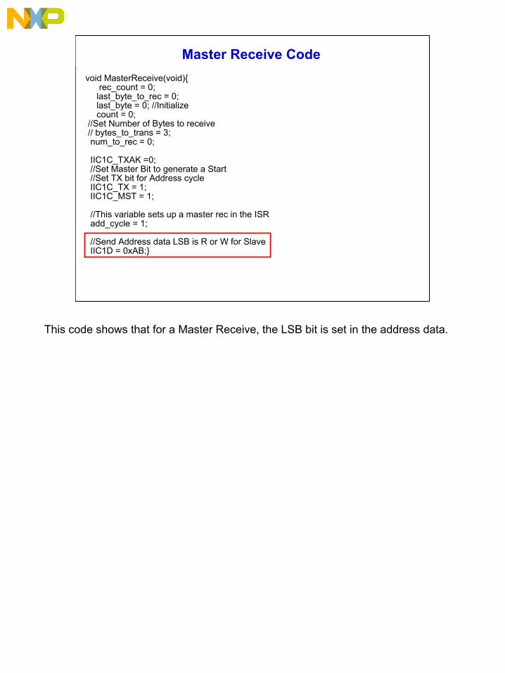
Master Receive Codevoid MasterReceive(void){
rec_count = 0;last_byte_to_rec = 0;last_byte = 0; //Initializecount = 0;
//Set Number of Bytes to receive// bytes_to_trans = 3;num_to_rec = 0;
IIC1C_TXAK =0;//Set Master Bit to generate a Start//Set TX bit for Address cycleIIC1C_TX = 1;IIC1C_MST = 1;
//This variable sets up a master rec in the ISRadd_cycle = 1;
//Send Address data LSB is R or W for SlaveIIC1D = 0xAB;}
This code shows that for a Master Receive, the LSB bit is set in the address data.
22
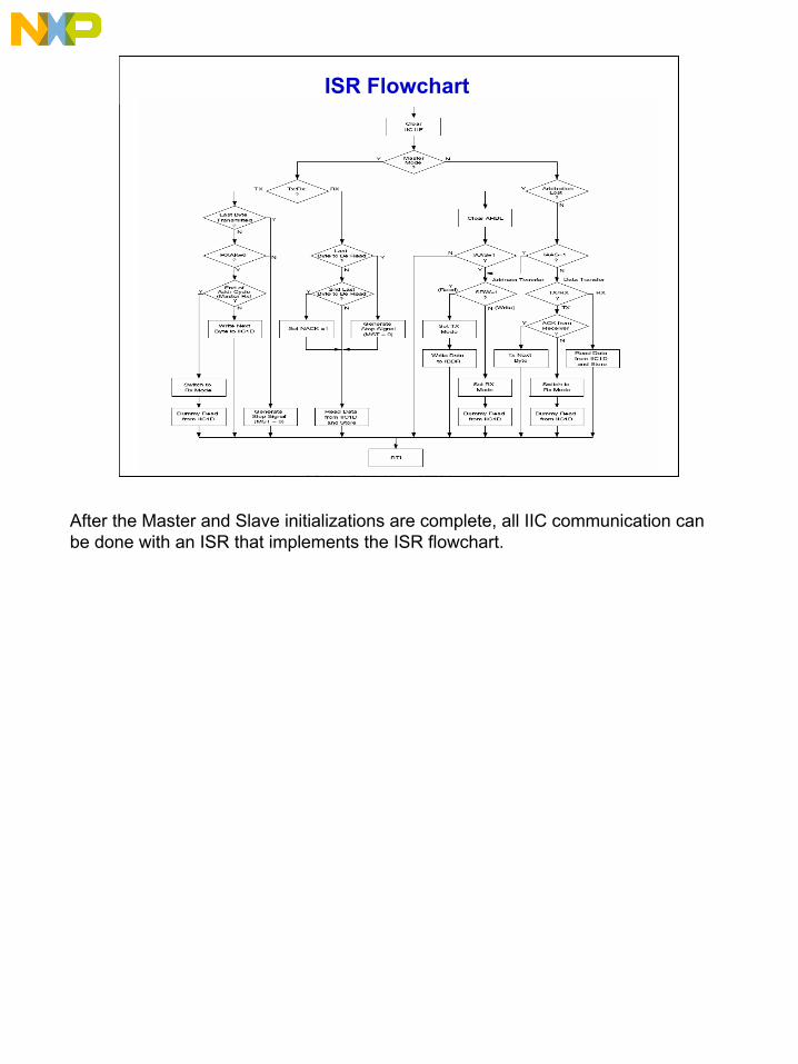
ISR Flowchart
After the Master and Slave initializations are complete, all IIC communication can be done with an ISR that implements the ISR flowchart.
23
Step 2
Step 2
Done Reset ShowSolution
Step 1
Step 1
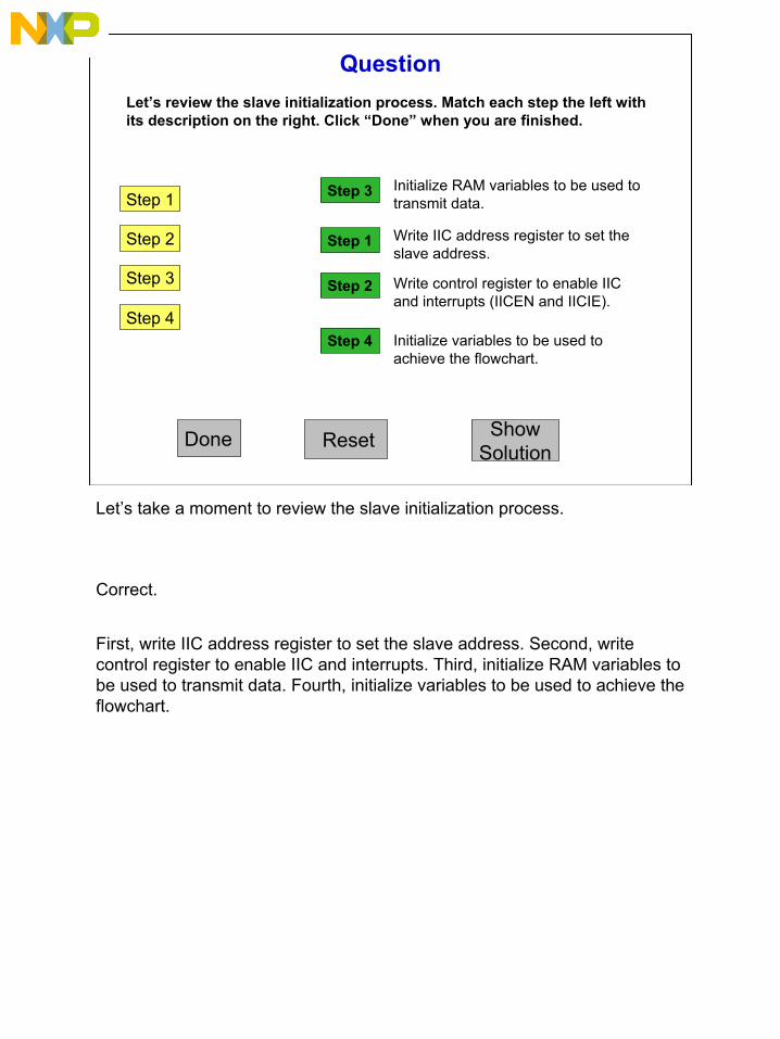
QuestionLet’s review the slave initialization process. Match each step the left with its description on the right. Click “Done” when you are finished.
Step 3
Step 4
Initialize RAM variables to be used to transmit data.
Write IIC address register to set the slave address.
Write control register to enable IIC and interrupts (IICEN and IICIE).
Initialize variables to be used to achieve the flowchart.
Step 3
Step 4
Let’s take a moment to review the slave initialization process.
Correct.
First, write IIC address register to set the slave address. Second, write control register to enable IIC and interrupts. Third, initialize RAM variables to be used to transmit data. Fourth, initialize variables to be used to achieve the flowchart.
24
Course Summary
• IIC features and uses
• IIC registers
• IIC protocol
• Master and slave operations
• IIC ISR flowchart
In this course, you learned about the IIC module, which provides a method of communication between devices on the same bus. You looked at its features and applications. For instance, this module is compatible with IIC bus industry standards, and it can be used in applications such as EEPROMs and temperature sensors. You also examined the IIC registers, which are address, frequency divide, control, status, and data registers.
Next you examined the IIC protocol. A normal transfer begins with a START signal, followed by a slave address transmission. Communication continues as long as an acknowledge signal is received and ends when a STOP signal (NACK) is received.
You learned important information on how to configure master and slave operations. In both operations, you needed to write the appropriate registers and initialize RAM variables to transmit data and achieve the ISR flowchart.
For additional information on how to use the IIC, refer to AN 3048.