
IC Design Front-End Solution - Silvaco · IC Design Front-End Solution Gateway Schematic Capture...
40
IC Design Front-End Solution Gateway, SmartSpice, and SmartView
Transcript of IC Design Front-End Solution - Silvaco · IC Design Front-End Solution Gateway Schematic Capture...

IC Design Front-End Solution
Gateway, SmartSpice, and SmartView

IC Design Front-End Solution
Gateway, SmartSpice and SmartView Agenda
Simucad’s Solution for Analog IC Front-End Design Gateway Schematic Capture and Editor SmartSpice Analog Circuit Simulator SmartView Waveform Viewer and Post-Processor
- 2 -

IC Design Front-End Solution
Gateway, SmartSpice and SmartView Agenda
Simucad’s Solution for Analog IC Front-End Design Gateway Schematic Capture and Editor SmartSpice Analog Circuit Simulator SmartView Waveform Viewer and Post-Processor
- 3 -

IC Design Front-End Solution
Simucad’s Solution for Analog IC Front-End Design
Gateway - Schematic Capture and Editor SmartSpice - Berkeley based SPICE simulator SmartView - Graphical postprocessor Advantages
Easy transition from other popular IC design tools User-friendly and intuitive design environment Design portability between platforms (SunOS, Windows, Linux) PDKs (process design kits) to provide standard pre-built design models,
cells, symbols, schematics for participating foundries
- 4 -

IC Design Front-End Solution
Analog/Mixed-Signal Design Flow
- 5 -

IC Design Front-End Solution
Agenda: Schematic Capture and Editor
Simucad’s Solution for Analog IC Front-End Design Gateway Schematic Capture and Editor SmartSpice Analog Circuit Simulator SmartView Waveform Viewer and Post-Processor
- 6 -

IC Design Front-End Solution
Gateway Schematic Capture and Editor
Powerful front-end schematic editor and viewer Tightly integrated with Simucad’s SmartSpice and Smartview tools Creates multi-sheet, multi-view, hierarchical, or flat designs Import\export of EDIF 2 0 0 schematics, symbols, and cells Intuitive left-to-right toolbar implementation to mirror design flow Dialog box approach for building SPICE analysis control cards Analog environment for ease of saving and plotting vectors Ability to switch processes and run process variant simulations on
the same schematic Generate both SPICE netlist and LVS netlist from same schematic Hierarchical DC bias for all currents and voltages
- 7 -
IC Design Front-End Solution
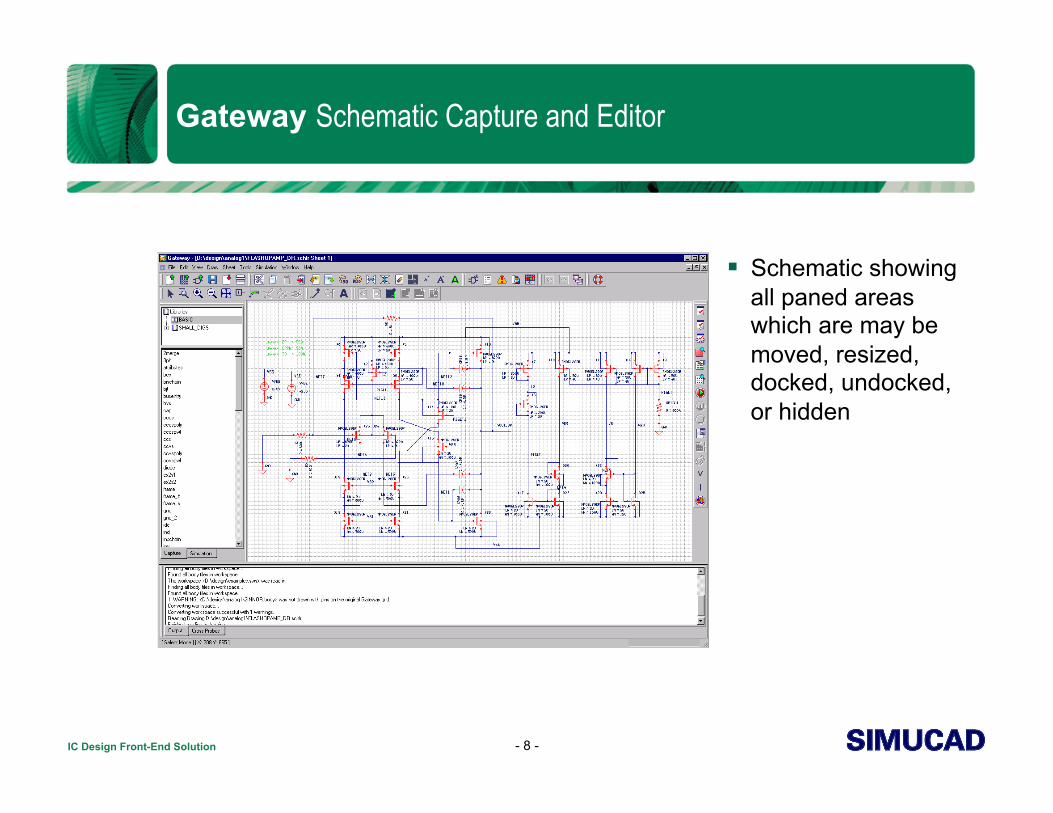
Gateway Schematic Capture and Editor
- 8 -
Schematic showing all paned areas which are may be moved, resized, docked, undocked, or hidden

IC Design Front-End Solution
Gateway Schematic Capture and Editor
Schematic Area may be maximized for largest possible drawing area
- 9 -

IC Design Front-End Solution
Gateway Schematic Capture and Editor
Two Modes of Operation Capture
Place Edit Check Save
Simulation Capture mode
shown at left
- 10 -
IC Design Front-End Solution
Gateway Schematic Capture and Editor
- 11 -
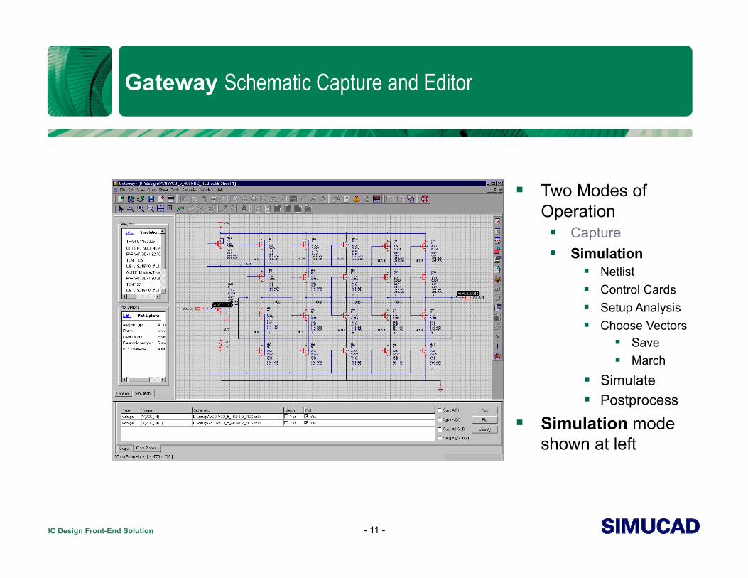
Two Modes of Operation Capture Simulation
Netlist Control Cards Setup Analysis Choose Vectors
Save March
Simulate Postprocess
Simulation mode shown at left
IC Design Front-End Solution
Gateway Schematic Capture and Editor
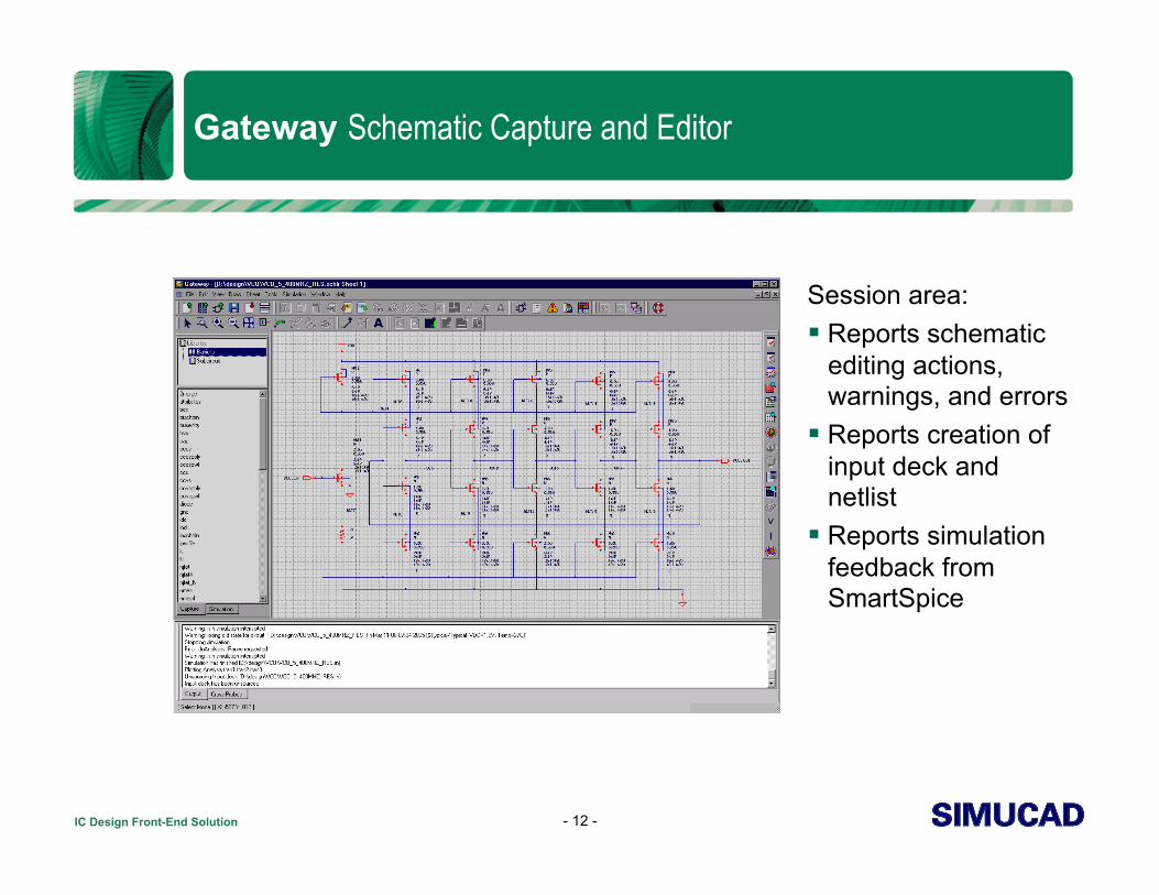
Session area: Reports schematic
editing actions, warnings, and errors
Reports creation of input deck and netlist
Reports simulation feedback from SmartSpice
- 12 -
IC Design Front-End Solution
Gateway Schematic Capture and Editor
- 13 -
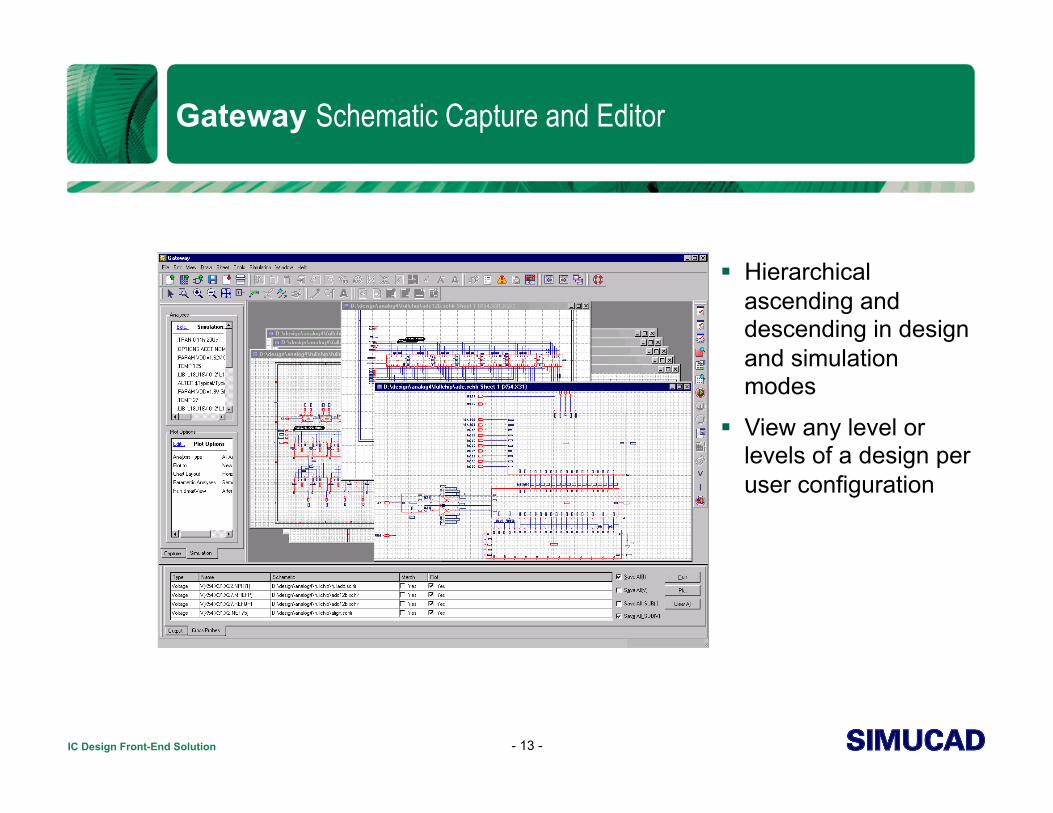
Hierarchical ascending and descending in design and simulation modes
View any level or levels of a design per user configuration

IC Design Front-End Solution
Gateway – Editing Instance Attributes
Spreadsheet style editor Changes in a single attribute
dialog may apply to: Only selected instance Selected instances Matching symbol instances All instances
Easy to change device models for all devices and generate subsequent runs
- 14 -
IC Design Front-End Solution
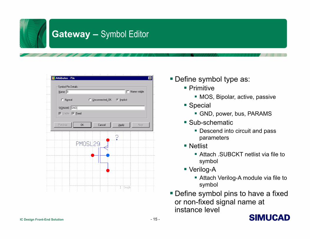
Gateway – Symbol Editor
Define symbol type as: Primitive
MOS, Bipolar, active, passive Special
GND, power, bus, PARAMS Sub-schematic
Descend into circuit and pass parameters
Netlist Attach .SUBCKT netlist via file to
symbol Verilog-A
Attach Verilog-A module via file to symbol
Define symbol pins to have a fixed or non-fixed signal name at instance level
- 15 -

IC Design Front-End Solution
Gateway – Symbol Editor
Define attributes to be changeable or fixed for the instance level Define expressions to be passed into the SPICE netlist Set attribute default values and visibilities Edit SmartSpice and Guardian Strings
- 16 -

IC Design Front-End Solution
Gateway – SmartSpice and Guardian Strings
Schematic Drawings generate two netlists: SmartSpice netlist (represents simulation netlist) Guardian netlist (represents LVS netlist)
Each symbol contains two strings: SmartSpice String Guardian String
Example: 4 terminal npn device (references a subcircuit definition for SmartSpice and a BJT transistor for LVS)
- 17 -
SmartSpice String: X_@PREFIX@PATH %C %B %E %VSUB XNPN AREA=@W $M
SmartSpice Netlist: X_Q27 NET8 BANDGAP NET2 GND XNPN AREA=1.5U M=1 X_Q28 BANDGAP NET8 NET3 GND XNPN AREA=5U M=1
Guardian String: @PREFIX@PATH %C %B %E %VSUB NPN AREA='(1.25U*AREA)'
Guardian Netlist: Q27 NET8 BANDGAP NET2 GND NPN AREA='(1.25U*AREA)' Q28 BANDGAP NET8 NET3 GND NPN AREA='(1.25U*AREA)'
IC Design Front-End Solution
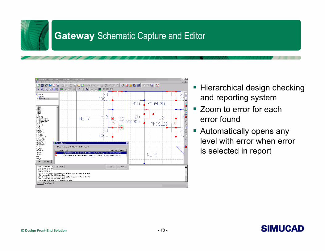
Gateway Schematic Capture and Editor
Hierarchical design checking and reporting system
Zoom to error for each error found
Automatically opens any level with error when error is selected in report
- 18 -

IC Design Front-End Solution
Gateway - Customize Settings
Set and save default settings for individuals or workgroups to file
Choose settings for integrated tools including: Set versions for SmartSpice and
SmartView Parallel SPICE and marching
waveforms Customized initialization files Schematic and symbol grid setting Sheet Border templates User-defined shortcuts and bindkeys Color settings Autosave and recovery
- 19 -
IC Design Front-End Solution
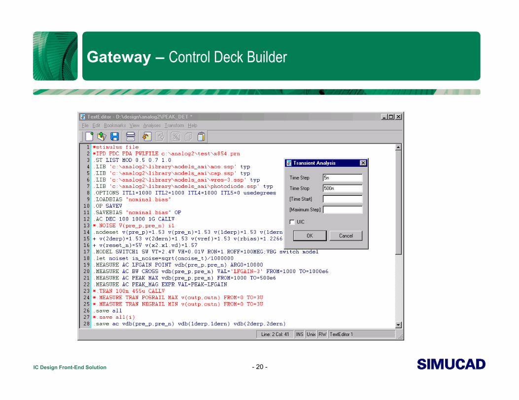
Gateway – Control Deck Builder
- 20 -
IC Design Front-End Solution
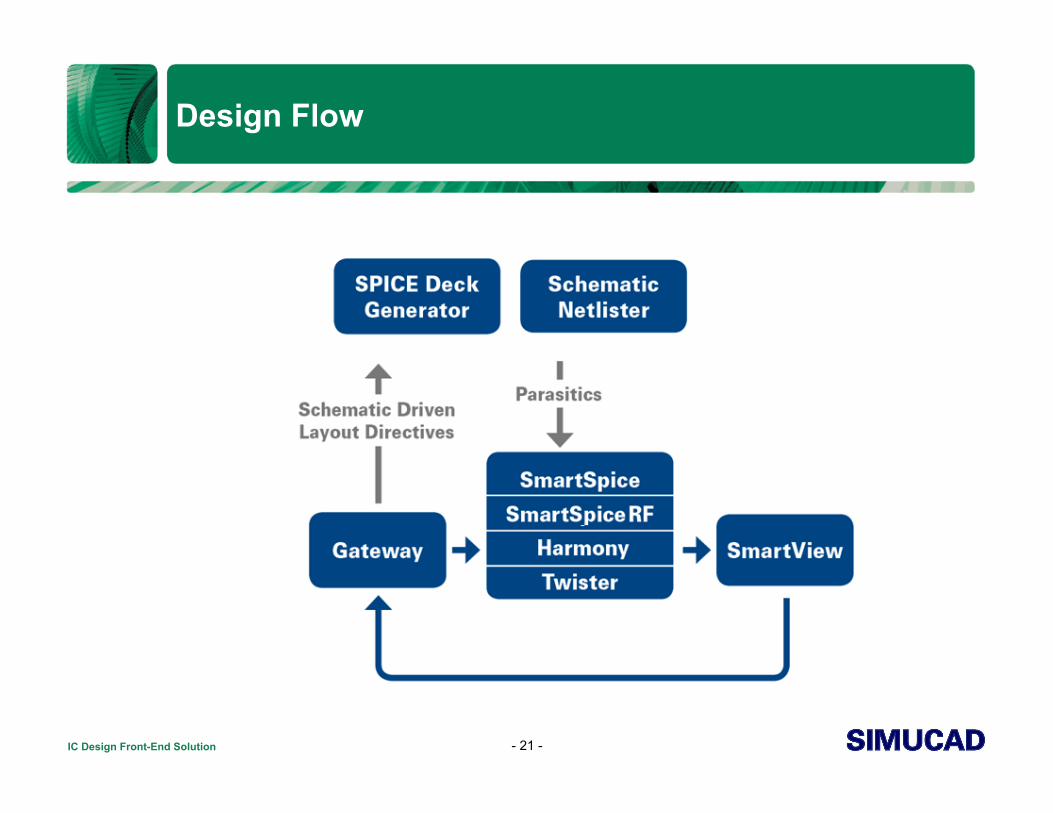
Design Flow
- 21 -
IC Design Front-End Solution
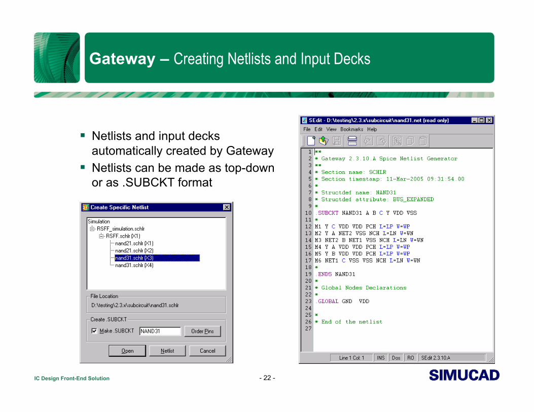
Gateway – Creating Netlists and Input Decks
Netlists and input decks automatically created by Gateway
Netlists can be made as top-down or as .SUBCKT format
- 22 -

IC Design Front-End Solution
Gateway – Pre-Simulation
Choose which analysis to plot Select what to be plotted:
Voltage markers on nodes Current markers on pins
Select what to be saved All currents and voltages Only what is marked Save from control deck Parametric data
Plot to: Existing plot Create new plot Overlay simulation runs
- 23 -

IC Design Front-End Solution
Gateway – During Simulation
Run-time dialog Final simulation time Current simulation time Timestep Temperature Number of CPUs
- 24 -

IC Design Front-End Solution
Gateway – DC Bias Current and Voltage
- 25 -
DC Bias Display When DCOP calculation
is finished Annotate Voltage Annotate Current Operates through
heriarchy

IC Design Front-End Solution
Gateway – After Simulation
SmartSpice finishes simulation
SmartSpice writes *.raw and *.out files
SmartView is launched The *.raw file is loaded
automatically into SmartView
Ready for cross-probing
- 26 -

IC Design Front-End Solution
Gateway – Running Verilog-A Circuits
Verilog-A modules may be mapped directly to symbols
Verilog-A circuits may be as compact models or as behavioral blocks, or both
Verilog-A circuits and regular analog primitive circuits may be mixed together and simulated
Results from analog primitive circuit and Verilog-A can be measured and overlaid
- 27 -

IC Design Front-End Solution
Gateway File Handling
- 28 -
IC Design Front-End Solution
Agenda: SmartSpice Analog Circuit Simulator
Simucad’s Solution for Analog IC Front-End Design Gateway Schematic Capture and Editor SmartSpice Analog Circuit Simulator SmartView Waveform Viewer and Post-Processor
- 29 -

IC Design Front-End Solution
SmartSpice – Analog Circuit Simulator
Industry leader in analog IC design simulation
Berkeley SPICE compatible Superior simulator in speed and
convergence 100% HSPICE™ compatible for
netlists, models, analysis features, and results
Capacity - up to 400 thousand active devices in 32 bit and 8 million active devices in 64 bit version
Modular design to include solvers, parsers, models, and engine
Supports latest technologies Supported on Solaris, Linux, and
Windows
- 30 -
IC Design Front-End Solution
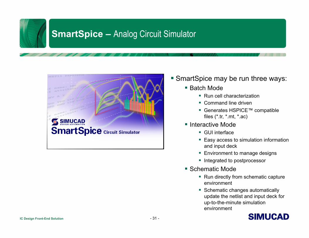
SmartSpice – Analog Circuit Simulator
SmartSpice may be run three ways: Batch Mode
Run cell characterization Command line driven Generates HSPICE™ compatible
files (*.tr, *.mt, *.ac)
Interactive Mode GUI interface Easy access to simulation information
and input deck Environment to manage designs Integrated to postprocessor
Schematic Mode Run directly from schematic capture
environment Schematic changes automatically
update the netlist and input deck for up-to-the-minute simulation environment
- 31 -

IC Design Front-End Solution
SmartSpice – Interactive Mode
Drag and drop input decks Choose an analysis Choose what to save or plot Run Simulation Display Statistics Open vector menu and plot results
- 32 -

IC Design Front-End Solution
SmartSpice – File Handling
- 33 -

IC Design Front-End Solution
Agenda: SmartView Waveform Viewer and Post-Processor
Simucad’s Solution for Analog IC Front-End Design Gateway Schematic Capture and Editor SmartSpice Analog Circuit Simulator SmartView Waveform Viewer and Post-Processor
- 34 -
IC Design Front-End Solution
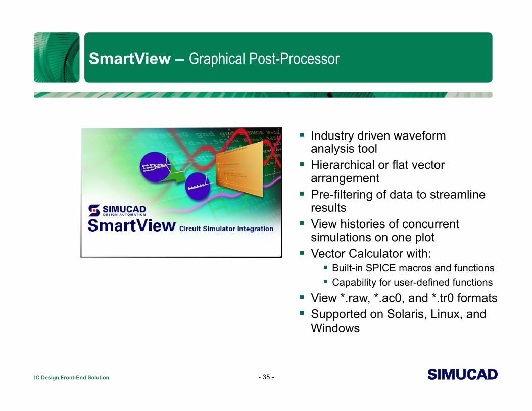
SmartView – Graphical Post-Processor
Industry driven waveform analysis tool
Hierarchical or flat vector arrangement
Pre-filtering of data to streamline results
View histories of concurrent simulations on one plot
Vector Calculator with: Built-in SPICE macros and functions Capability for user-defined functions
View *.raw, *.ac0, and *.tr0 formats Supported on Solaris, Linux, and
Windows
- 35 -

IC Design Front-End Solution
SmartView – Graphical Post-Processor
User-sizeable areas for plots, lists, and data
Drag and drop capability from vector tree into plot
Toolbars Standard Customizable Dockable
Merge or delete vectors across single or split plots
Undo and redo capability
- 36 -

IC Design Front-End Solution
SmartView – Graphical Post-Processor
Various measuring devices View more than one rawfile
at a time Simultaneous zooming
between plots Time synchronized panning
and zooming between plots Changing axis from linear
to log Context sensitive menus for
all plot objects
- 37 -
IC Design Front-End Solution
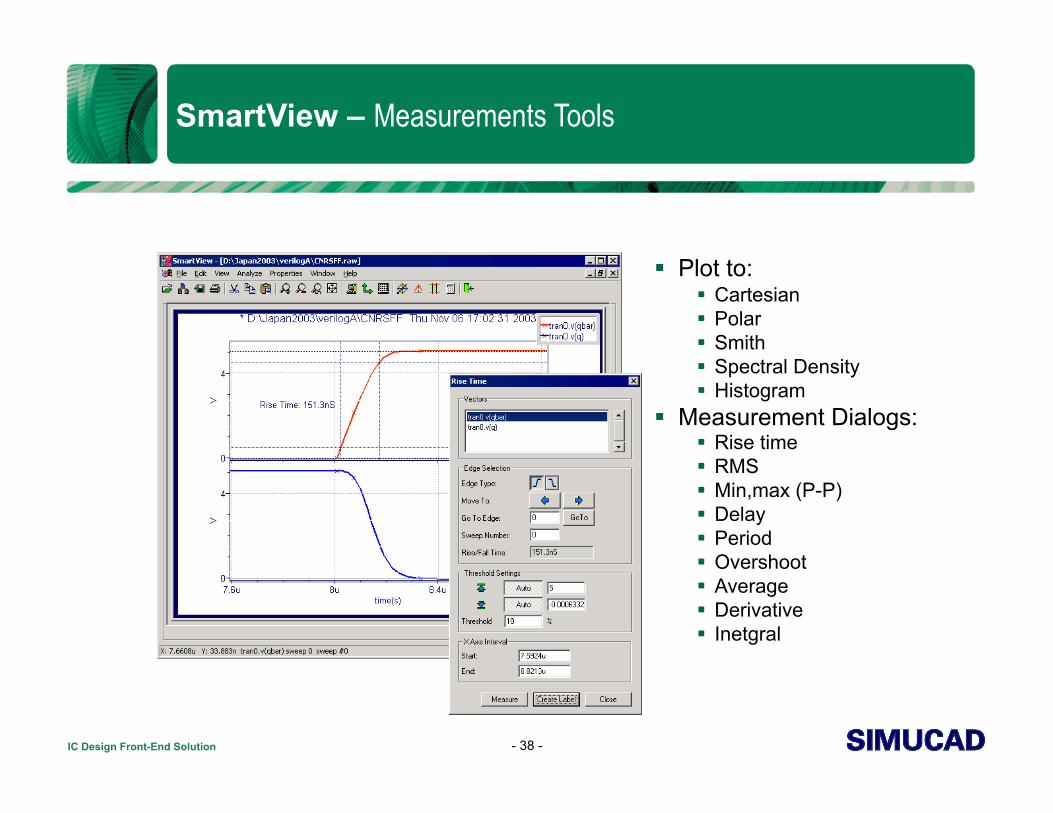
SmartView – Measurements Tools
Plot to: Cartesian Polar Smith Spectral Density Histogram
Measurement Dialogs: Rise time RMS Min,max (P-P) Delay Period Overshoot Average Derivative Inetgral
- 38 -

IC Design Front-End Solution
SmartView – Analyzing Parametrics
Parametric Analysis View sweeps merged View sweeps separate by
variable and value Ability to combine and split
sweeps
Sweep manager Manage all sweeps in rawfile Choose which sweeps to
display Handles multiple parametric
runs and secondary sweeps
- 39 -

IC Design Front-End Solution
Conclusion
AMS Toolflow Environment Schematic, Simulation, and Postprocessor tightly integrated Unified GUI environment for seamless interaction Designs can be ported easily between platforms
Solaris, Windows, Linux Compatible with major foundry design kits Easy transition into Simucad flow from other vendors
- 40 -