
IC Design Front-End Solution - Silvaco · IC Design Front-End Solution • Powerful front-end...
40
IC Design Front-End Solution Gateway, SmartSpice, and SmartView
Transcript of IC Design Front-End Solution - Silvaco · IC Design Front-End Solution • Powerful front-end...

IC Design Front-End Solution
Gateway, SmartSpice, and SmartView
IC Design Front-End Solution
• Silvaco’s Solution for Analog IC Front-End Design • Gateway Schematic Capture and Editor • SmartSpice Analog Circuit Simulator • SmartView Waveform Viewer and Post-Processor
Gateway, SmartSpice and SmartView Agenda
- 2 -
IC Design Front-End Solution
• Silvaco’s Solution for Analog IC Front-End Design • Gateway Schematic Capture and Editor • SmartSpice Analog Circuit Simulator • SmartView Waveform Viewer and Post-Processor
Gateway, SmartSpice and SmartView Agenda
- 3 -
IC Design Front-End Solution
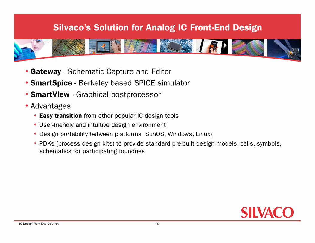
• Gateway - Schematic Capture and Editor • SmartSpice - Berkeley based SPICE simulator • SmartView - Graphical postprocessor • Advantages
• Easy transition from other popular IC design tools • User-friendly and intuitive design environment • Design portability between platforms (SunOS, Windows, Linux)
• PDKs (process design kits) to provide standard pre-built design models, cells, symbols, schematics for participating foundries
Silvaco’s Solution for Analog IC Front-End Design
- 4 -
IC Design Front-End Solution
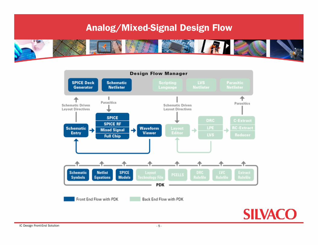
Analog/Mixed-Signal Design Flow
- 5 -
IC Design Front-End Solution
• Silvaco’s Solution for Analog IC Front-End Design • Gateway Schematic Capture and Editor • SmartSpice Analog Circuit Simulator • SmartView Waveform Viewer and Post-Processor
Agenda: Schematic Capture and Editor
- 6 -
IC Design Front-End Solution
• Powerful front-end schematic editor and viewer • Tightly integrated with Silvaco’s SmartSpice and Smartview tools • Creates multi-sheet, multi-view, hierarchical, or flat designs • Import\export of EDIF 2 0 0 schematics, symbols, and cells • Intuitive left-to-right toolbar implementation to mirror design flow • Dialog box approach for building SPICE analysis control cards • Analog environment for ease of saving and plotting vectors • Ability to switch processes and run process variant simulations on the
same schematic • Generate both SPICE netlist and LVS netlist from same schematic • Hierarchical DC bias for all currents and voltages
Gateway Schematic Capture and Editor
- 7 -
IC Design Front-End Solution
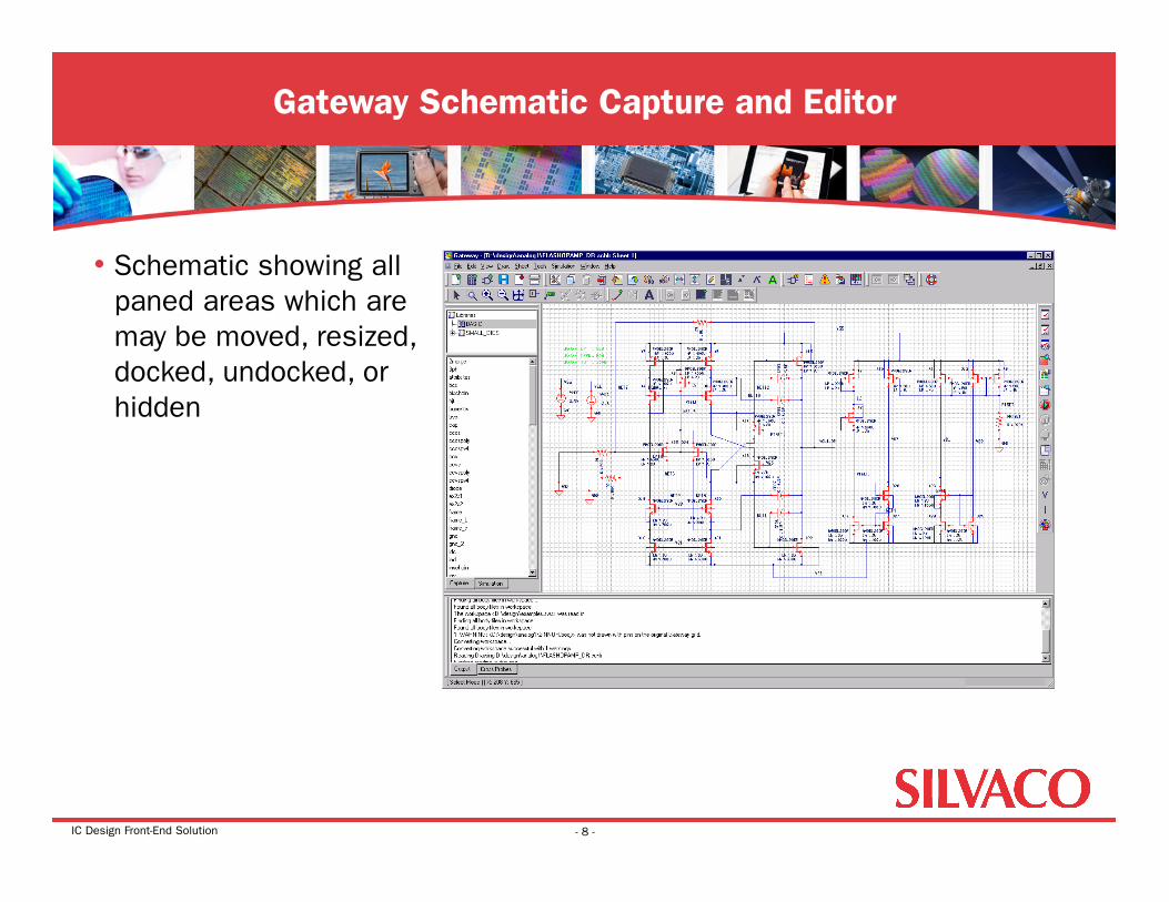
• Schematic showing all paned areas which are may be moved, resized, docked, undocked, or hidden
Gateway Schematic Capture and Editor
- 8 -
IC Design Front-End Solution
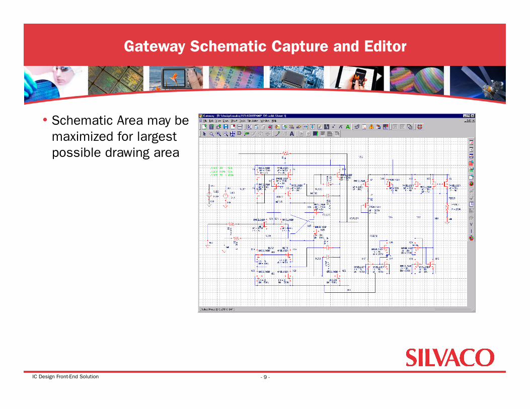
• Schematic Area may be maximized for largest possible drawing area
Gateway Schematic Capture and Editor
- 9 -
IC Design Front-End Solution
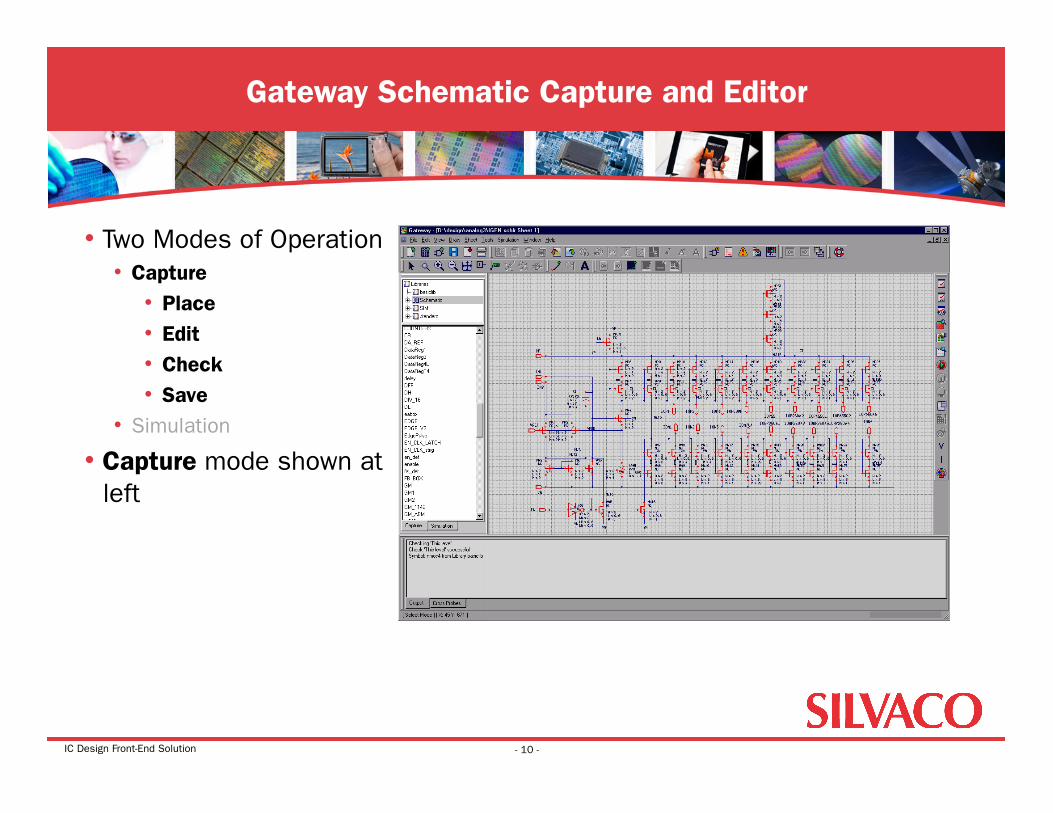
• Two Modes of Operation • Capture
• Place • Edit • Check • Save
• Simulation
• Capture mode shown at left
Gateway Schematic Capture and Editor
- 10 -
IC Design Front-End Solution
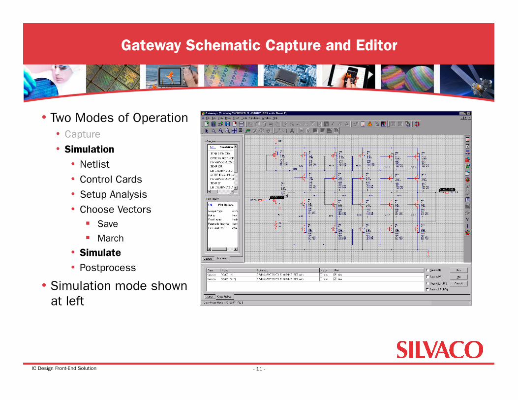
• Two Modes of Operation • Capture • Simulation
• Netlist • Control Cards • Setup Analysis • Choose Vectors
Save
March
• Simulate • Postprocess
• Simulation mode shown at left
Gateway Schematic Capture and Editor
- 11 -
IC Design Front-End Solution
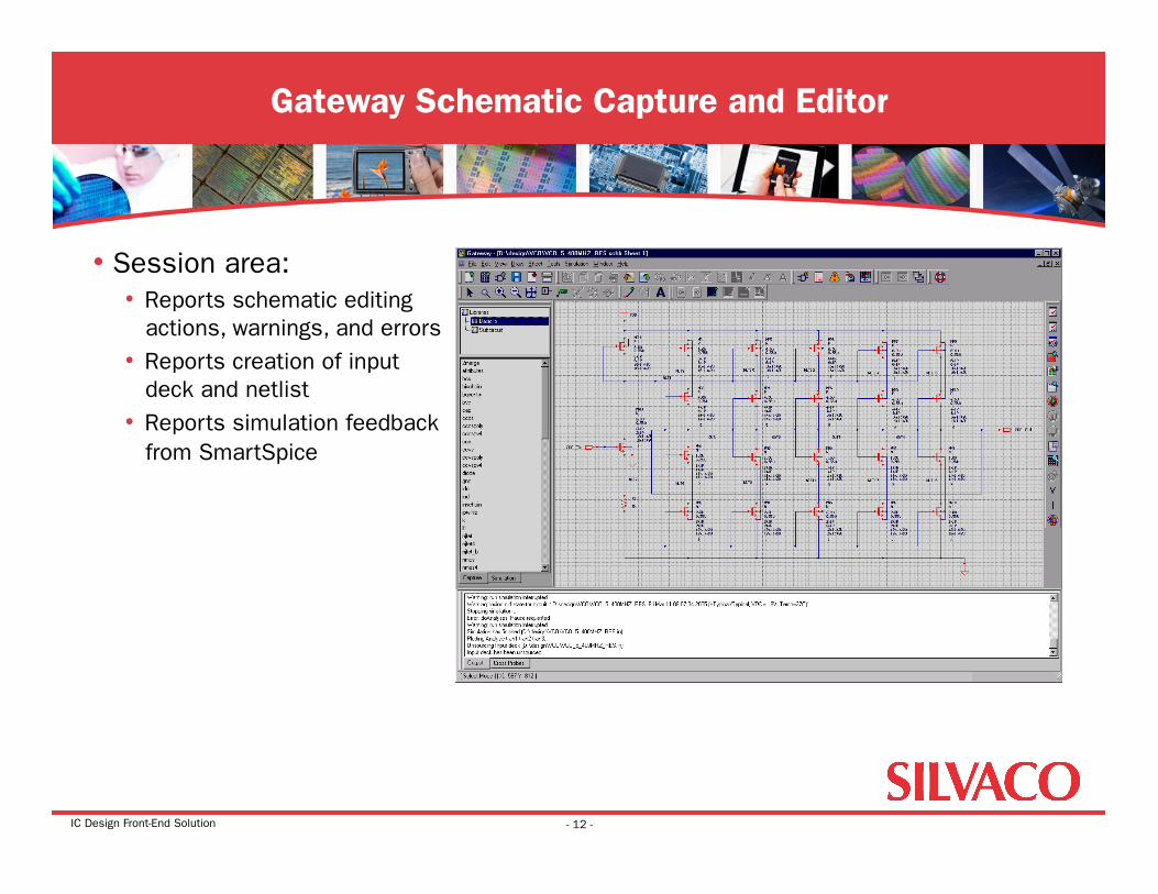
• Session area: • Reports schematic editing
actions, warnings, and errors • Reports creation of input
deck and netlist • Reports simulation feedback
from SmartSpice
Gateway Schematic Capture and Editor
- 12 -
IC Design Front-End Solution
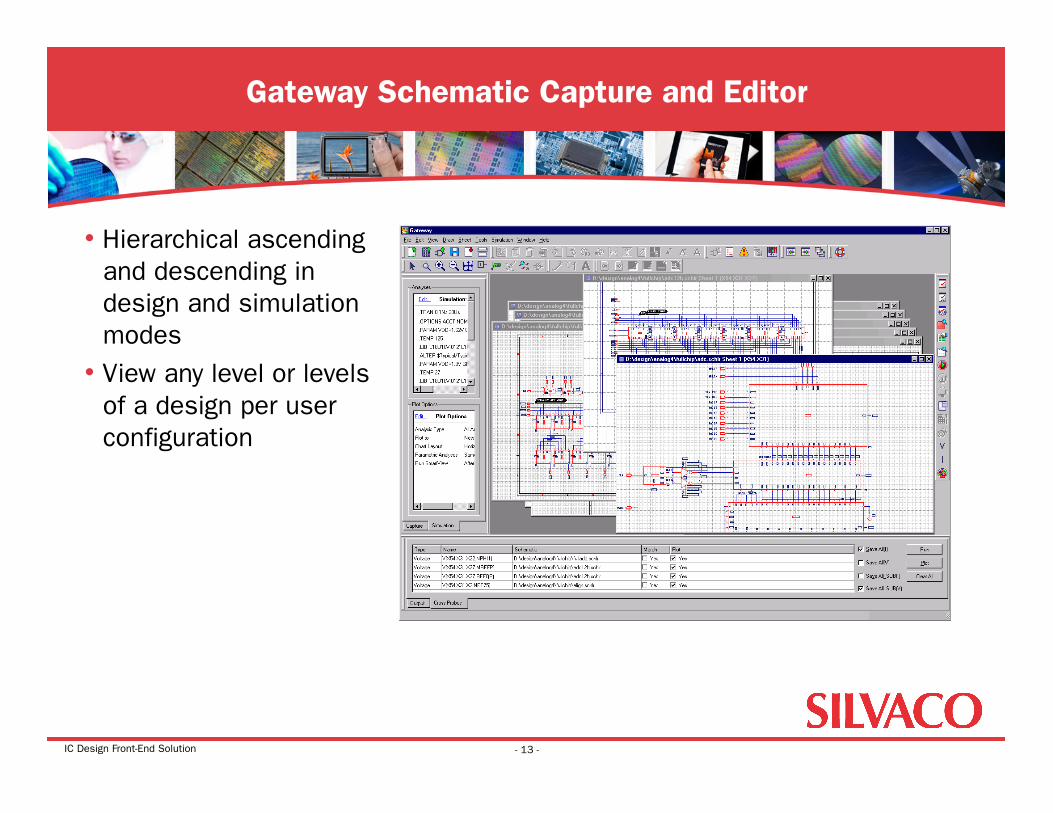
• Hierarchical ascending and descending in design and simulation modes
• View any level or levels of a design per user configuration
Gateway Schematic Capture and Editor
- 13 -
IC Design Front-End Solution
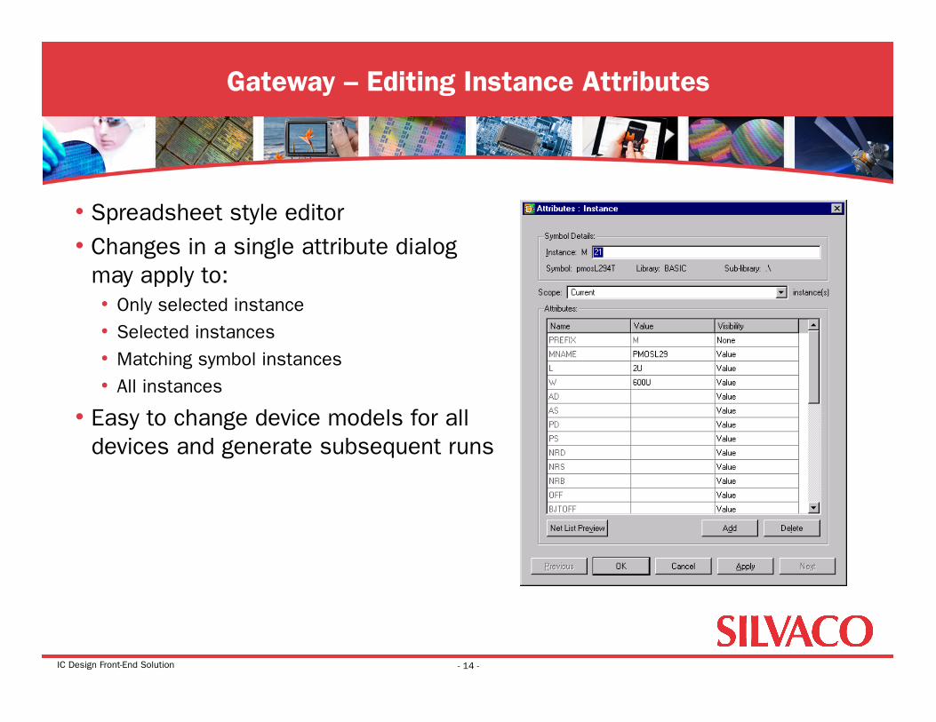
• Spreadsheet style editor • Changes in a single attribute dialog
may apply to: • Only selected instance • Selected instances • Matching symbol instances • All instances
• Easy to change device models for all devices and generate subsequent runs
Gateway – Editing Instance Attributes
- 14 -
IC Design Front-End Solution
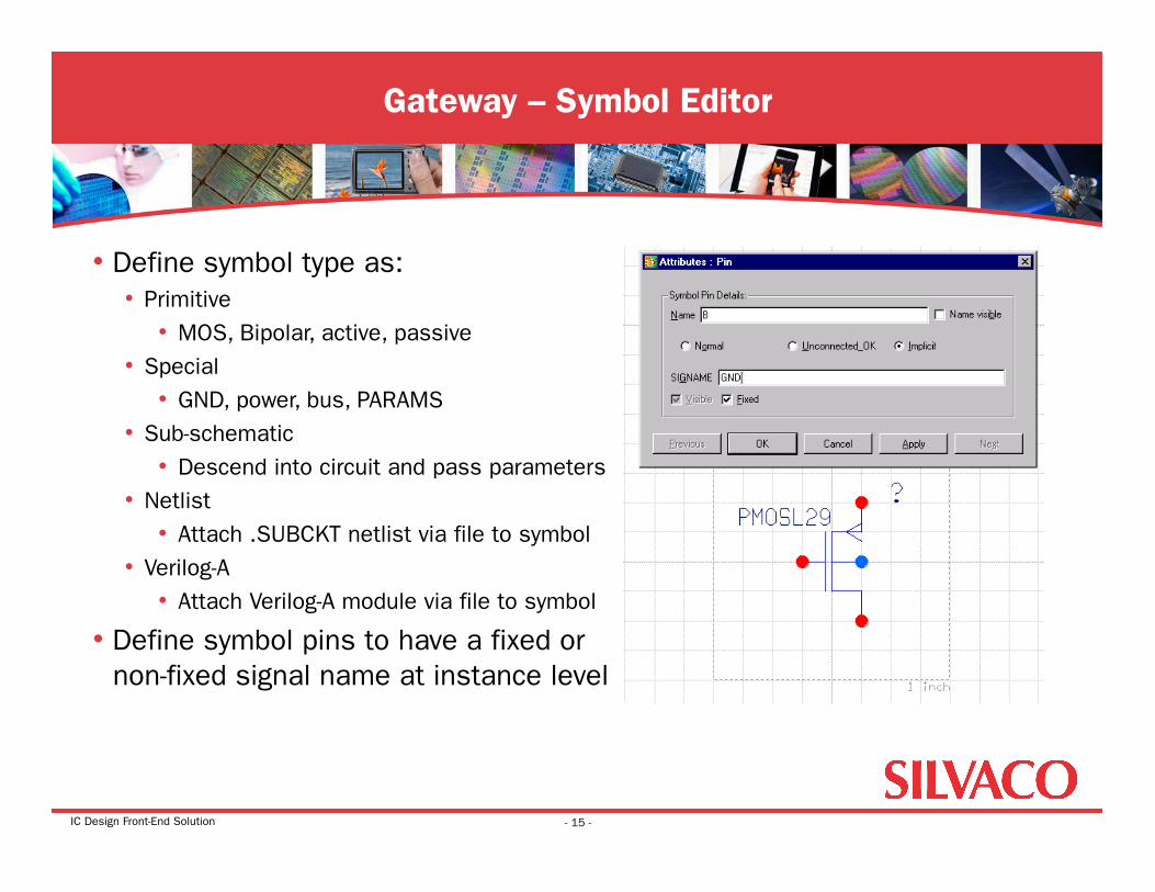
• Define symbol type as: • Primitive
• MOS, Bipolar, active, passive • Special
• GND, power, bus, PARAMS • Sub-schematic
• Descend into circuit and pass parameters • Netlist
• Attach .SUBCKT netlist via file to symbol • Verilog-A
• Attach Verilog-A module via file to symbol
• Define symbol pins to have a fixed or non-fixed signal name at instance level
Gateway – Symbol Editor
- 15 -
IC Design Front-End Solution
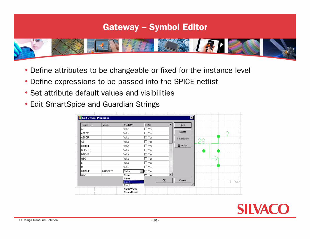
• Define attributes to be changeable or fixed for the instance level • Define expressions to be passed into the SPICE netlist • Set attribute default values and visibilities • Edit SmartSpice and Guardian Strings
Gateway – Symbol Editor
- 16 -
IC Design Front-End Solution
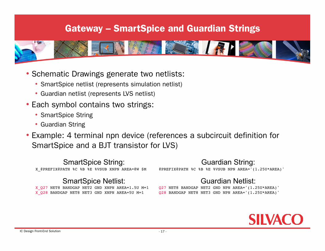
• Schematic Drawings generate two netlists: • SmartSpice netlist (represents simulation netlist) • Guardian netlist (represents LVS netlist)
• Each symbol contains two strings: • SmartSpice String • Guardian String
• Example: 4 terminal npn device (references a subcircuit definition for SmartSpice and a BJT transistor for LVS)
Gateway – SmartSpice and Guardian Strings
- 17 -
SmartSpice String: X_@PREFIX@PATH %C %B %E %VSUB XNPN AREA=@W $M
SmartSpice Netlist: X_Q27 NET8 BANDGAP NET2 GND XNPN AREA=1.5U M=1!X_Q28 BANDGAP NET8 NET3 GND XNPN AREA=5U M=1
Guardian String: @PREFIX@PATH %C %B %E %VSUB NPN AREA='(1.25U*AREA)'!
Guardian Netlist: Q27 NET8 BANDGAP NET2 GND NPN AREA='(1.25U*AREA)' Q28 BANDGAP NET8 NET3 GND NPN AREA='(1.25U*AREA)'!
IC Design Front-End Solution
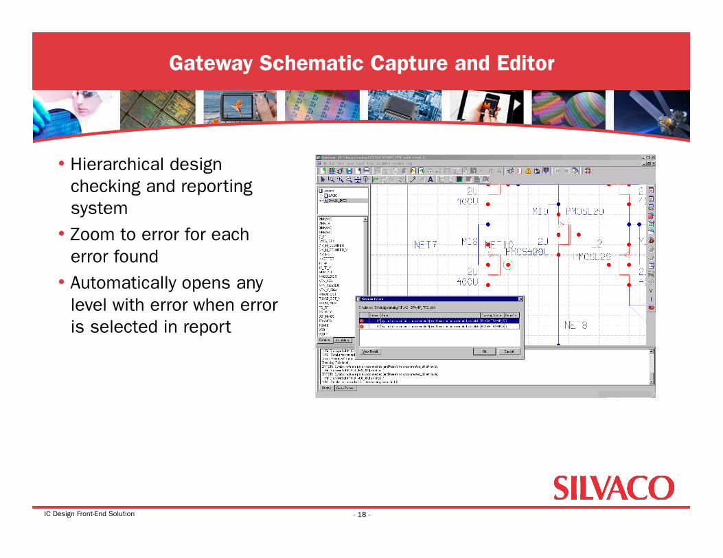
• Hierarchical design checking and reporting system
• Zoom to error for each error found
• Automatically opens any level with error when error is selected in report
Gateway Schematic Capture and Editor
- 18 -
IC Design Front-End Solution
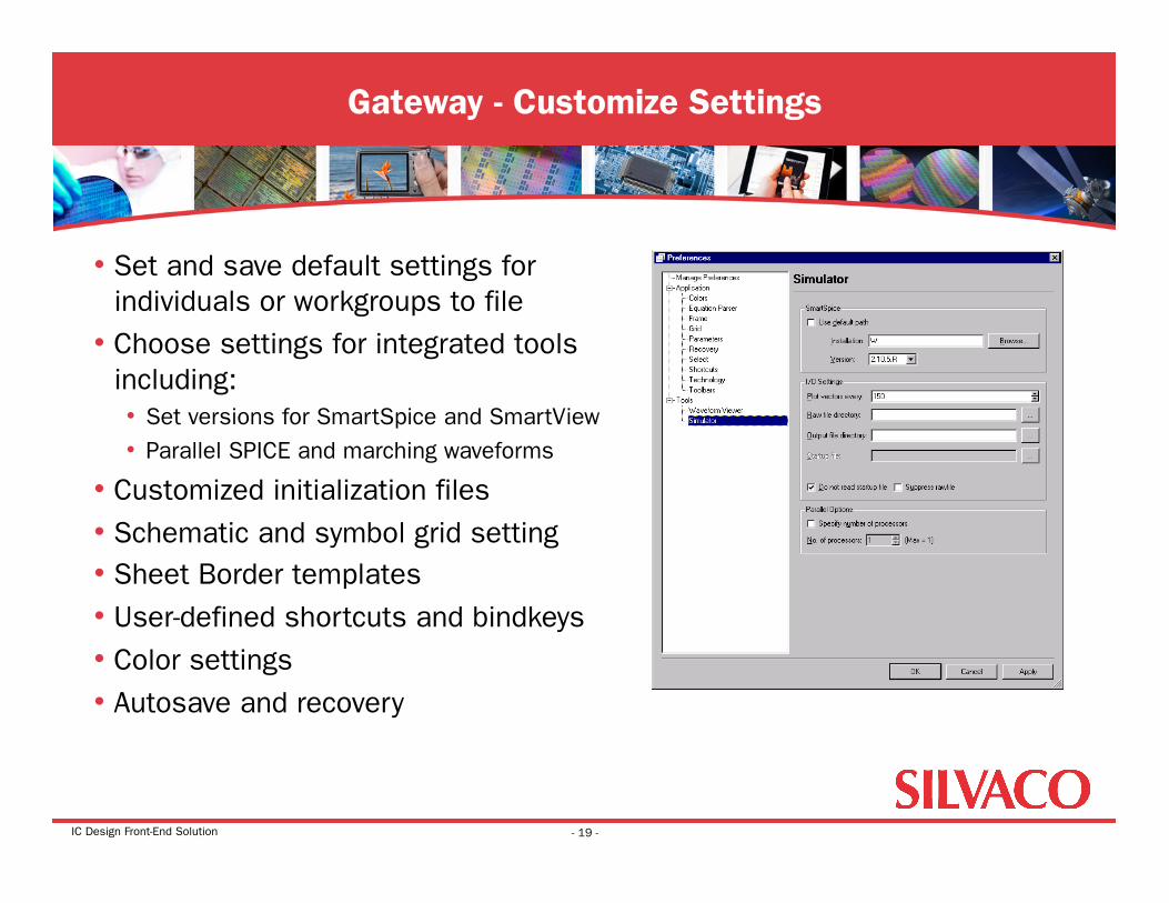
• Set and save default settings for individuals or workgroups to file
• Choose settings for integrated tools including: • Set versions for SmartSpice and SmartView • Parallel SPICE and marching waveforms
• Customized initialization files • Schematic and symbol grid setting • Sheet Border templates • User-defined shortcuts and bindkeys • Color settings • Autosave and recovery
Gateway - Customize Settings
- 19 -
IC Design Front-End Solution
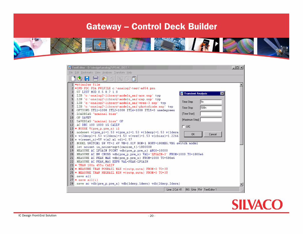
Gateway – Control Deck Builder
- 20 -
IC Design Front-End Solution
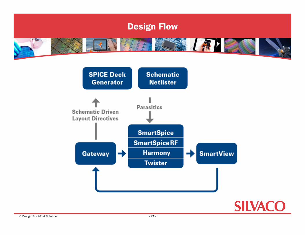
Design Flow
- 21 -
IC Design Front-End Solution
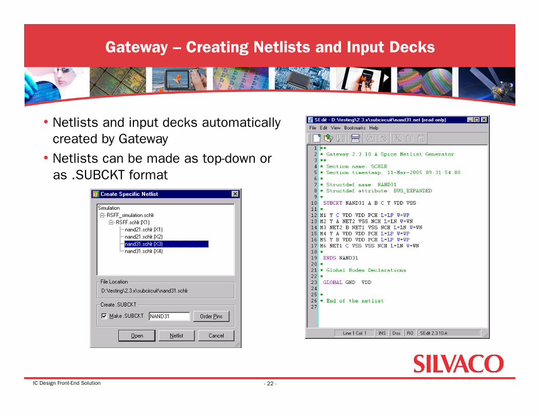
• Netlists and input decks automatically created by Gateway
• Netlists can be made as top-down or as .SUBCKT format
Gateway – Creating Netlists and Input Decks
- 22 -
IC Design Front-End Solution
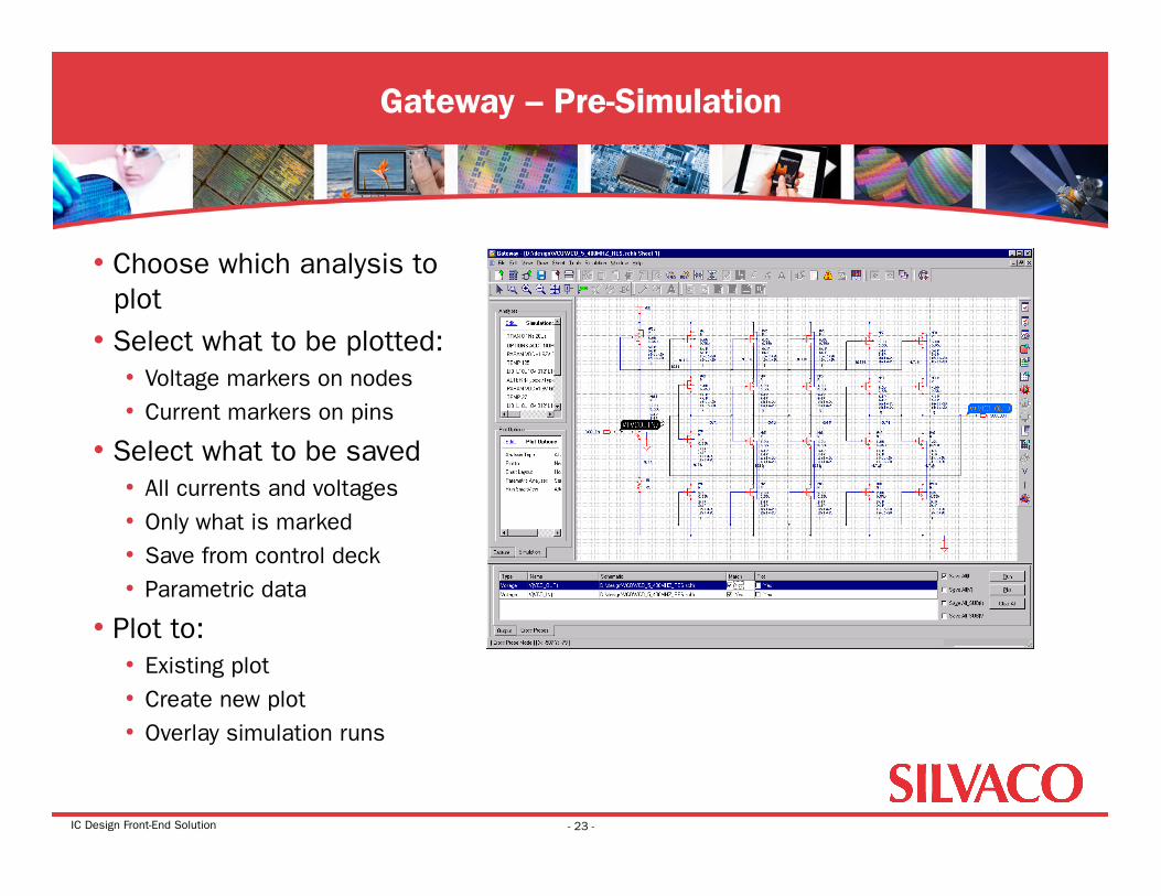
• Choose which analysis to plot
• Select what to be plotted: • Voltage markers on nodes • Current markers on pins
• Select what to be saved • All currents and voltages • Only what is marked • Save from control deck • Parametric data
• Plot to: • Existing plot • Create new plot • Overlay simulation runs
Gateway – Pre-Simulation
- 23 -
IC Design Front-End Solution
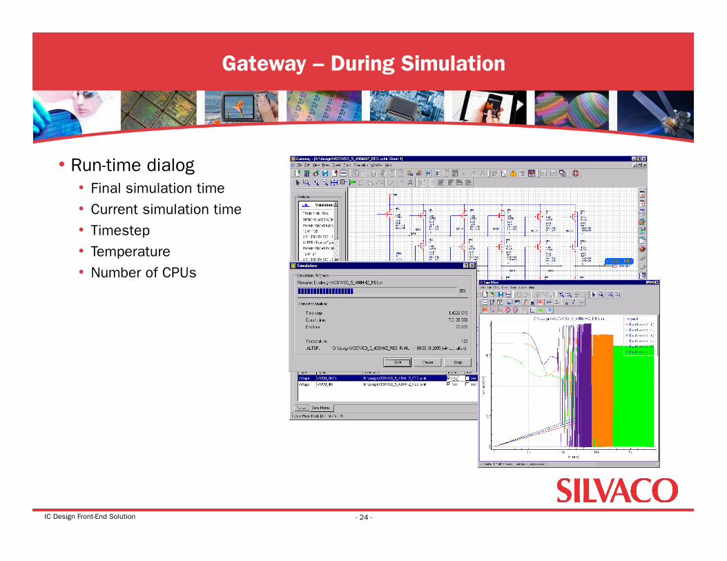
• Run-time dialog • Final simulation time • Current simulation time • Timestep • Temperature • Number of CPUs
Gateway – During Simulation
- 24 -
IC Design Front-End Solution
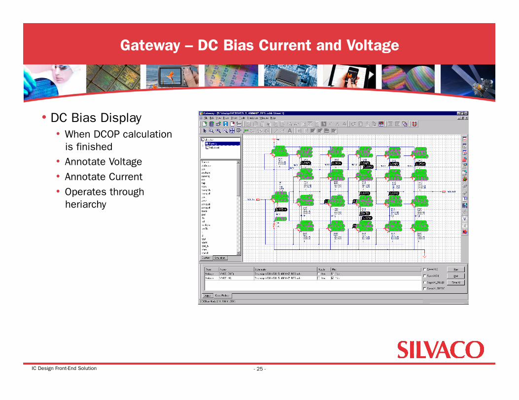
• DC Bias Display • When DCOP calculation
is finished • Annotate Voltage • Annotate Current • Operates through
heriarchy
Gateway – DC Bias Current and Voltage
- 25 -
IC Design Front-End Solution
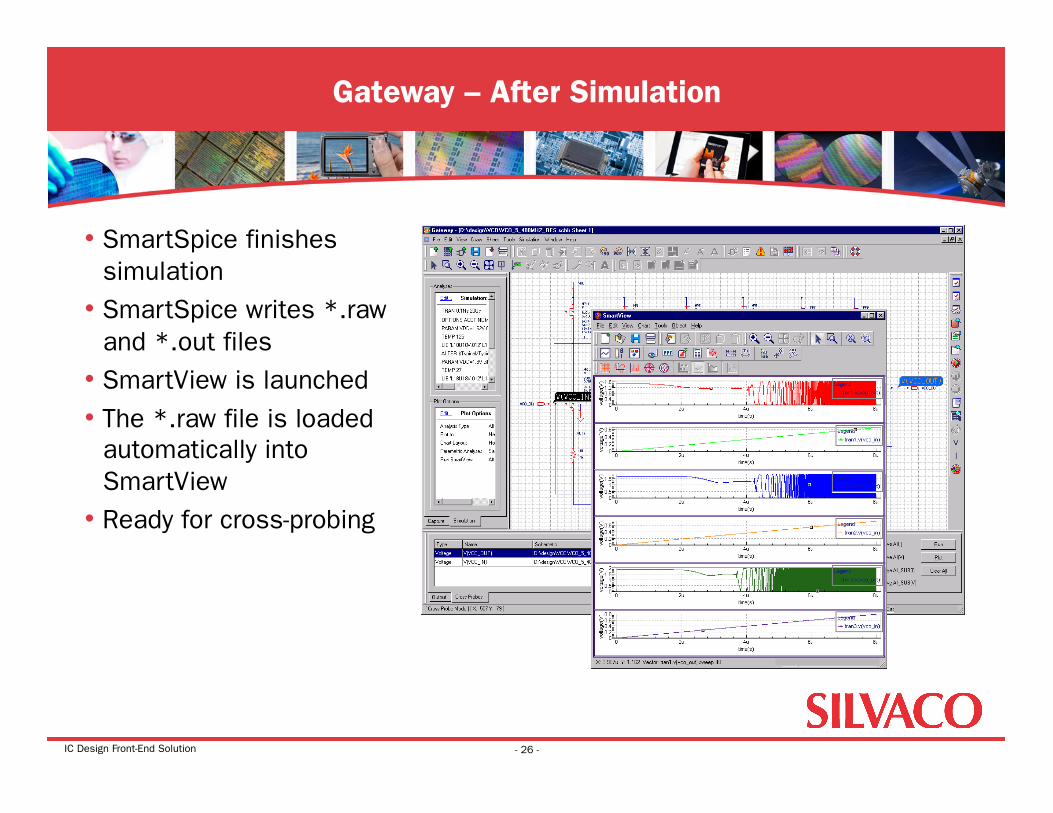
• SmartSpice finishes simulation
• SmartSpice writes *.raw and *.out files
• SmartView is launched • The *.raw file is loaded
automatically into SmartView
• Ready for cross-probing
Gateway – After Simulation
- 26 -
IC Design Front-End Solution
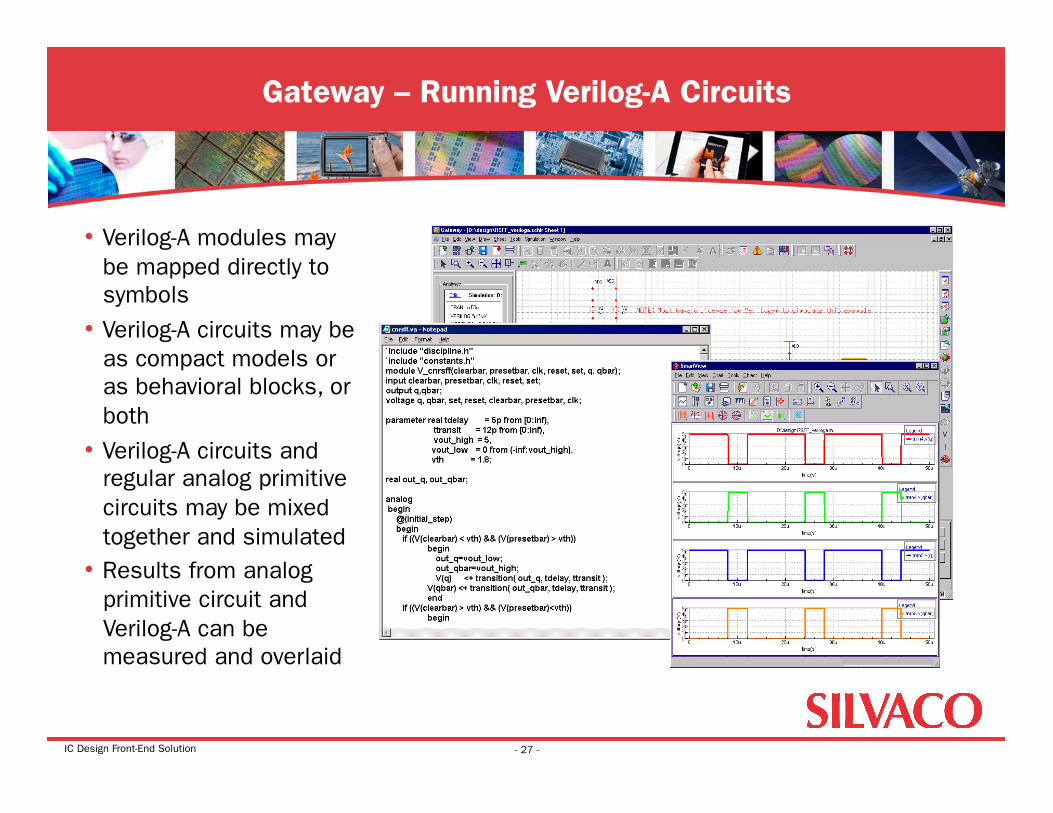
• Verilog-A modules may be mapped directly to symbols
• Verilog-A circuits may be as compact models or as behavioral blocks, or both
• Verilog-A circuits and regular analog primitive circuits may be mixed together and simulated
• Results from analog primitive circuit and Verilog-A can be measured and overlaid
Gateway – Running Verilog-A Circuits
- 27 -
IC Design Front-End Solution
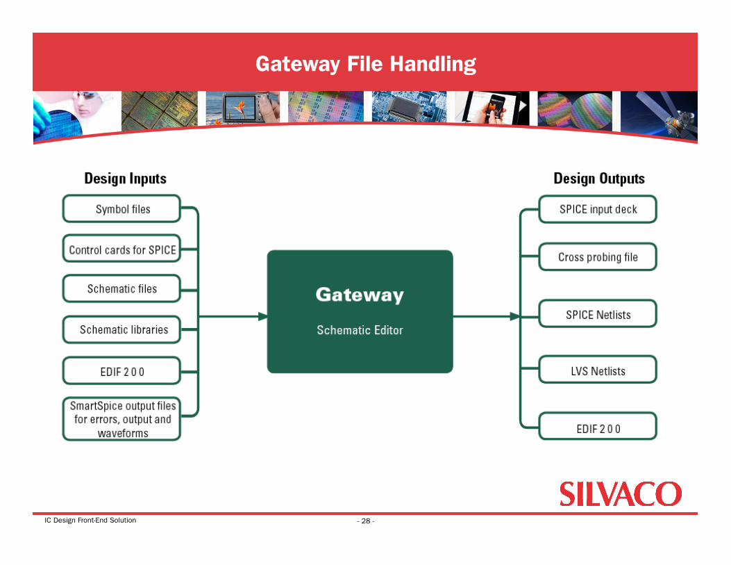
Gateway File Handling
- 28 -
IC Design Front-End Solution
• Silvaco’s Solution for Analog IC Front-End Design • Gateway Schematic Capture and Editor • SmartSpice Analog Circuit Simulator • SmartView Waveform Viewer and Post-Processor
Agenda: SmartSpice Analog Circuit Simulator
- 29 -
IC Design Front-End Solution
• Industry leader in analog IC design simulation • Berkeley SPICE compatible • Superior simulator in speed and convergence • 100% HSPICE™ compatible for netlists,
models, analysis features, and results • Capacity - up to 400 thousand active devices
in 32 bit and 8 million active devices in 64 bit version • Modular design to include solvers, parsers, models, and engine • Supports latest technologies • Supported on Solaris, Linux, and Windows
SmartSpice – Analog Circuit Simulator
- 30 -
IC Design Front-End Solution
• SmartSpice may be run three ways: • Batch Mode
• Run cell characterization • Command line driven • Generates HSPICE™ compatible files
(*.tr, *.mt, *.ac) • Interactive Mode
• GUI interface • Easy access to simulation information and input deck • Environment to manage designs
• Integrated to postprocessor • Schematic Mode
• Run directly from schematic capture environment • Schematic changes automatically update the netlist and input deck for up-to-the-
minute simulation environment
SmartSpice – Analog Circuit Simulator
- 31 -
IC Design Front-End Solution
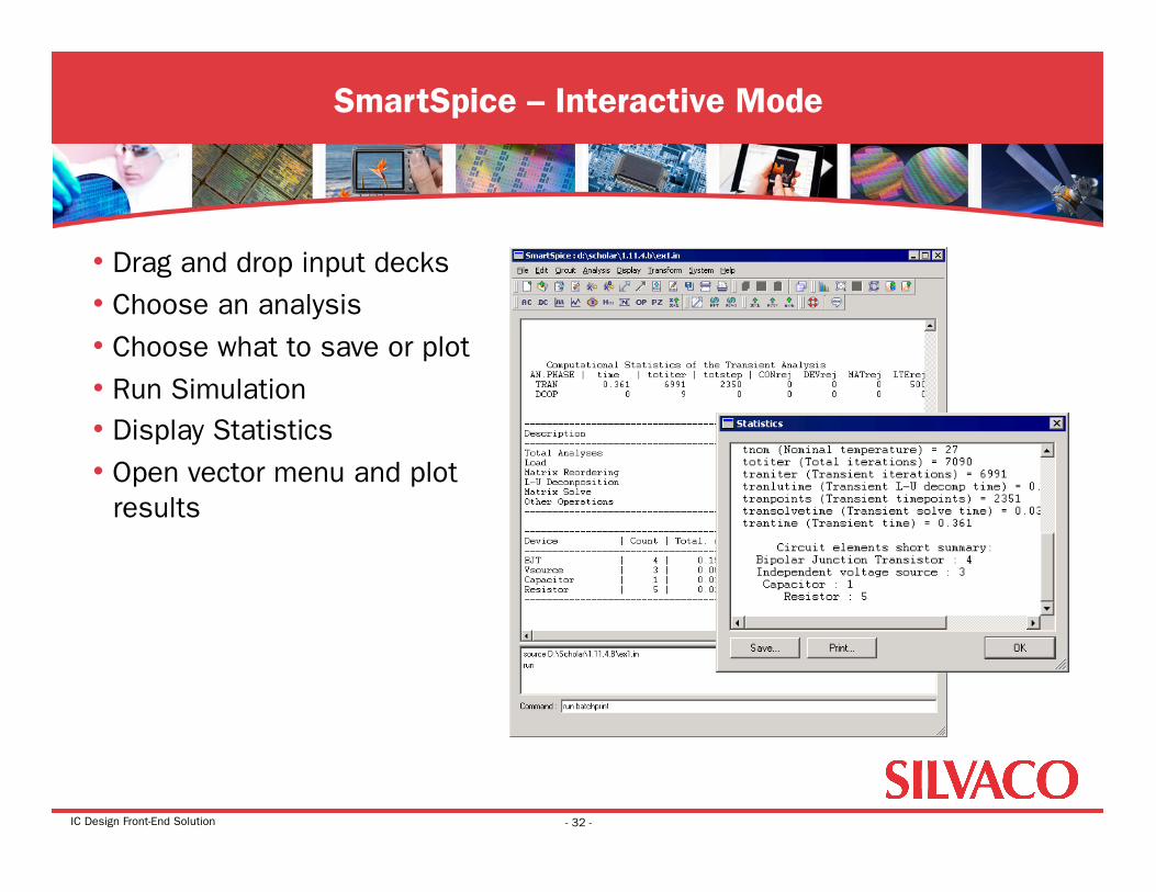
• Drag and drop input decks • Choose an analysis • Choose what to save or plot • Run Simulation • Display Statistics • Open vector menu and plot
results
SmartSpice – Interactive Mode
- 32 -
IC Design Front-End Solution
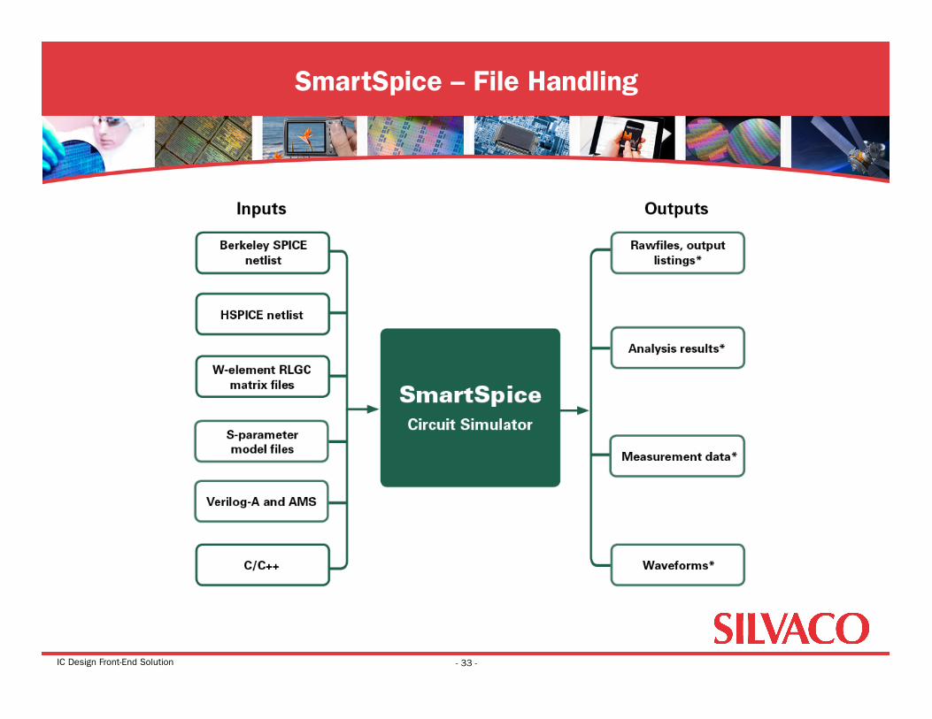
SmartSpice – File Handling
- 33 -
IC Design Front-End Solution
• Silvaco’s Solution for Analog IC Front-End Design • Gateway Schematic Capture and Editor • SmartSpice Analog Circuit Simulator • SmartView Waveform Viewer and Post-Processor
Agenda: SmartView Waveform Viewer and Post-Processor
- 34 -
IC Design Front-End Solution
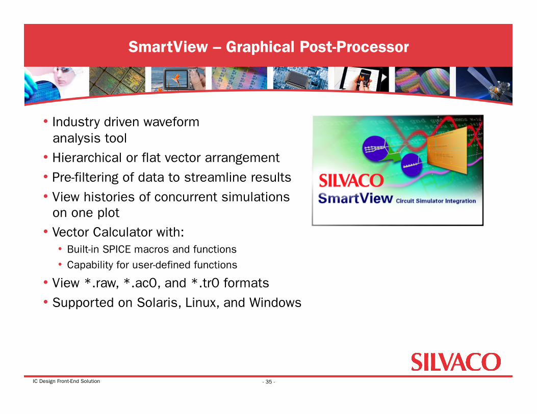
• Industry driven waveform analysis tool
• Hierarchical or flat vector arrangement • Pre-filtering of data to streamline results • View histories of concurrent simulations
on one plot • Vector Calculator with:
• Built-in SPICE macros and functions • Capability for user-defined functions
• View *.raw, *.ac0, and *.tr0 formats • Supported on Solaris, Linux, and Windows
SmartView – Graphical Post-Processor
- 35 -
IC Design Front-End Solution
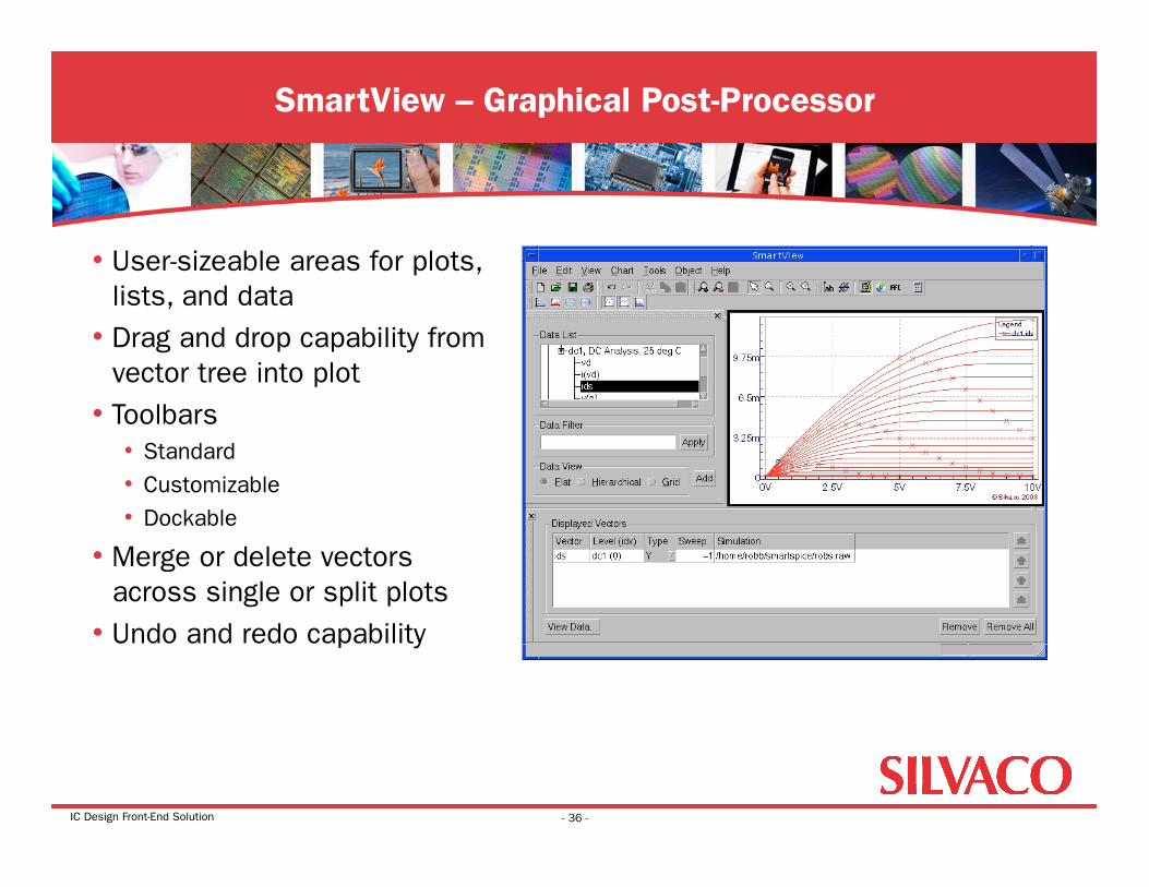
• User-sizeable areas for plots, lists, and data
• Drag and drop capability from vector tree into plot
• Toolbars • Standard • Customizable • Dockable
• Merge or delete vectors across single or split plots
• Undo and redo capability
SmartView – Graphical Post-Processor
- 36 -
IC Design Front-End Solution
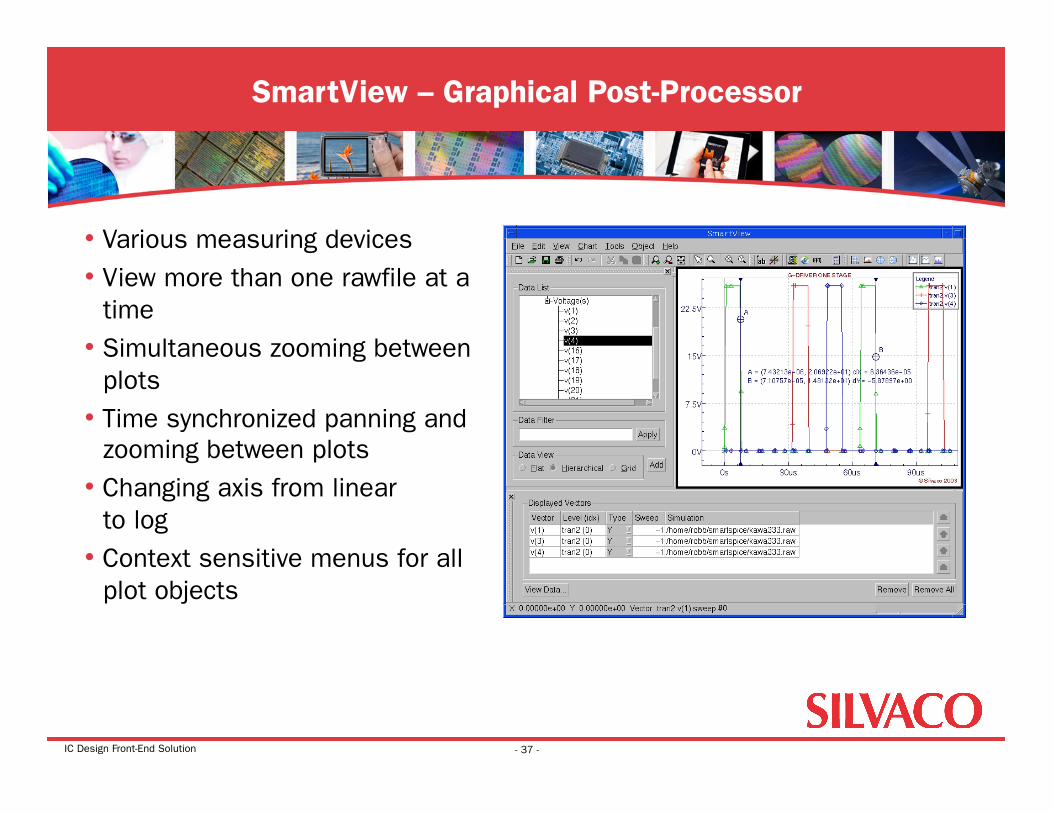
• Various measuring devices • View more than one rawfile at a
time • Simultaneous zooming between
plots • Time synchronized panning and
zooming between plots • Changing axis from linear
to log • Context sensitive menus for all
plot objects
SmartView – Graphical Post-Processor
- 37 -
IC Design Front-End Solution
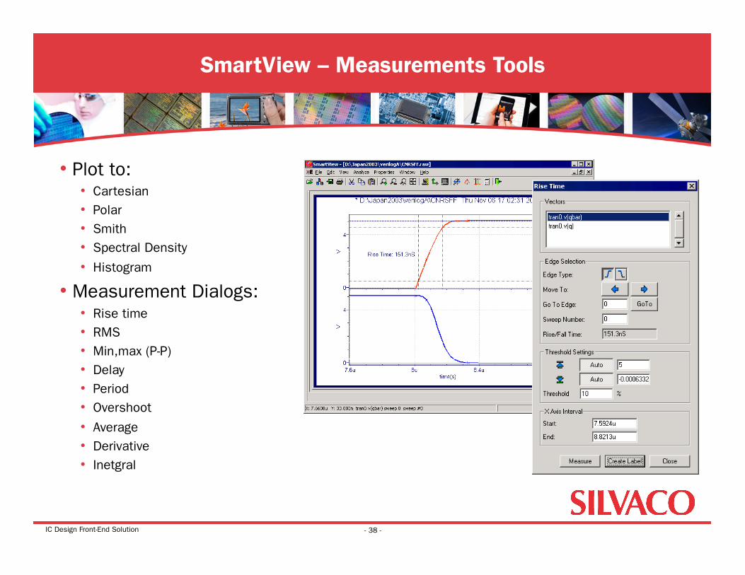
• Plot to: • Cartesian • Polar • Smith • Spectral Density
• Histogram
• Measurement Dialogs: • Rise time • RMS • Min,max (P-P) • Delay • Period • Overshoot
• Average • Derivative • Inetgral
SmartView – Measurements Tools
- 38 -
IC Design Front-End Solution
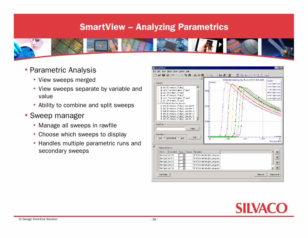
• Parametric Analysis • View sweeps merged • View sweeps separate by variable and
value • Ability to combine and split sweeps
• Sweep manager • Manage all sweeps in rawfile • Choose which sweeps to display • Handles multiple parametric runs and
secondary sweeps
SmartView – Analyzing Parametrics
- 39 -
IC Design Front-End Solution
• AMS Toolflow Environment • Schematic, Simulation, and Postprocessor tightly integrated • Unified GUI environment for seamless interaction • Designs can be ported easily between platforms
• Solaris, Windows, Linux • Compatible with major foundry design kits • Easy transition into Silvaco flow from other vendors
Conclusion
- 40 -