I-Series Hydraulic Suction Scanning Filter Manual · I-Series Filter Manual, Rev. 2, 12/2018 Page 8...
24
I-Series Hydraulic Suction Scanning Filter Manual Revision 2, December 2018
Transcript of I-Series Hydraulic Suction Scanning Filter Manual · I-Series Filter Manual, Rev. 2, 12/2018 Page 8...
I-SeriesHydraulic Suction Scanning Filter Manual
Revision 2, December 2018

I-Series Filter Manual, Rev. 2, 12/2018 Page 2
Table of Contents
SECTION I INTRODUCTION ............................................................................................................. 4 1.1 Description ..................................................................................................................... 4 1.2 Theory of operation ....................................................................................................... 4 1.3 Recommended Applications ........................................................................................ 5 1.4 Design Features ............................................................................................................. 5 1.5 Filter Specifications Chart ............................................................................................ 6
SECTION II INSTALLATION ............................................................................................................... 7
2.1 Mechanical Hook-Up and Orientation .......................................................................... 7 2.2 Plumbing ........................................................................................................................ 7 2.3 Piston and Electric Ball Valve (EBV) Installation ....................................................... 7 2.4 Controller Connections ................................................................................................. 8 2.5 Pressure Differential Lines ........................................................................................... 9
SECTION III OPERATION AND ADJUSTMENTS ......................................................................... 10
3.1 Start-Up ......................................................................................................................... 10 3.2 Cleaning Cycle Requirements .................................................................................... 11
3.2.1 WORKING PRESSURE ........................................................................................... 11
3.2.2 PROCESS FLOW..................................................................................................... 11
3.2.3 FLUSH FLOW .......................................................................................................... 11
SECTION IV MAINTENANCE ......................................................................................................... 13
4.1 Shutdown Procedure ................................................................................................... 13 4.2 Filter Cleaning .............................................................................................................. 13 4.3 Dirt Collector Replacement ......................................................................................... 14 4.4 Piston Removal/Replacement .................................................................................... 14 4.5 Periodic Inspection ...................................................................................................... 14
SECTION V TROUBLESHOOTING GUIDE ...................................................................................... 15
5.1 Problem: Excessive pressure drop through filter without flushing ....................... 15 5.2 Problem: Frequent or continuous flushing while filling main pipeline .................. 15 5.3 Problem: Frequent flushing during normal operation ............................................. 15 5.4 Problem: Screen will not clean properly ................................................................... 16
SECTION VI SPARE PARTS .......................................................................................................... 17
6.1 Recommended Spare Parts ........................................................................................ 17
Appendix I Alternate Flushing Methods ...................................................................................... 18
Appendix II System with Discharge to Atmosphere .................................................................... 19
Appendix III Piston ......................................................................................................................... 19
Appendix IV Pressure Drop vs Micron ........................................................................................... 21
Appendix V Standard Filter Warranty ............................................................................................ 22

Tech Support: 866-477-9778 [email protected] Page 3
Check List for Optimal Filter Performance
☐ There should be no back-pressure on the flush line. A 2” valve
should have a 3” flush line. Do not use rubber hosing or flexible tubing
for the waste line.
☐ The fitting on the side of the piston is for venting only. It should be
open to atmospheric and point toward the ground.
☐ If the filter outlet discharges to a tank or to open atmosphere, a
valve should be installed at the filter outlet to maintain a minimum
working pressure of 40 PSI during the cleaning cycle.
☐ If the flush valve fails to open or close, verify the wiring to the
controller is intact and connected properly. (see diagram on pg.
8).
☐ A surge protector should be installed before the electronic controller.
☐ The filter should be oriented so that the unfiltered water source is
directed to the inlet, the flange closest to the cover. The outlet, the flange
closest to the flush line, is the source of filtered water.
For Technical Support:
Tel: 866-477-9778
Email: [email protected]

I-Series Filter Manual, Rev. 2, 12/2018 Page 4
SECTION I INTRODUCTION
1.1 Description
The I-Series Hydraulic Suction Scanning Filter features automatic, self-cleaning, screen type water filters. The filtration system consists of a filter body, first stage coarse screen, second stage fine screen, flushing valve, and an electronic controller.
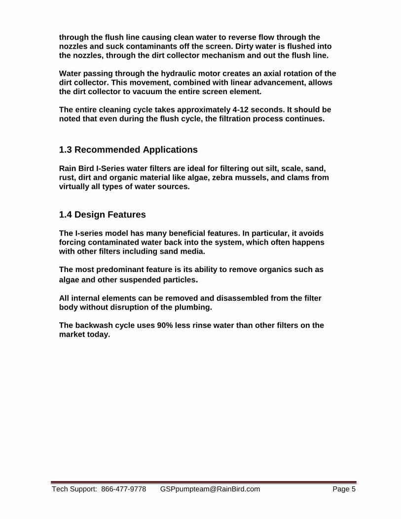
1.2 Theory of operation
Pressurized water enters the filter inlet and travels through a 3/8" perforated stainless steel coarse screen (¼” for smaller models) where large particles are pre-filtered. The water then passes through a fine mesh stainless steel screen where small contaminants (down to 10 microns in size) are filtered. Clean water then exits through the outlet.
When the fine screen becomes contaminated, a pressure differential is created. A differential pressure switch senses this and sends a signal to the automatic controller which opens the flush valve. Water then flows
Tech Support: 866-477-9778 [email protected] Page 5
through the flush line causing clean water to reverse flow through the nozzles and suck contaminants off the screen. Dirty water is flushed into the nozzles, through the dirt collector mechanism and out the flush line.
Water passing through the hydraulic motor creates an axial rotation of the dirt collector. This movement, combined with linear advancement, allows the dirt collector to vacuum the entire screen element.
The entire cleaning cycle takes approximately 4-12 seconds. It should be noted that even during the flush cycle, the filtration process continues.
1.3 Recommended Applications
Rain Bird I-Series water filters are ideal for filtering out silt, scale, sand, rust, dirt and organic material like algae, zebra mussels, and clams from virtually all types of water sources.
1.4 Design Features
The I-series model has many beneficial features. In particular, it avoids forcing contaminated water back into the system, which often happens with other filters including sand media.
The most predominant feature is its ability to remove organics such as
algae and other suspended particles.
All internal elements can be removed and disassembled from the filter body without disruption of the plumbing.
The backwash cycle uses 90% less rinse water than other filters on the market today.

I-Series Filter Manual, Rev. 2, 12/2018 Page 6
1.5 Filter Specifications Chart
Model Flange Size Screen Area Max. Flow Empty Weight
Inch Sq. In. GPM Lbs.
HT-I-04-PE-S-M 4 720 600 425
HT-I-06-PE-S-G 6 720 800 400
HT-I-08-PS-S-G 8 1,008 1,400 650
HT-I-08-PE-S-G 8 1,152 1,500 510
HT-I-10-PS-S-G 10 1,584 2,200 900
HT-I-10-PE-S-G 10 1,800 3,200 510
HT-I-12-PS-S-G 12 1,800 3,400 1,005
Other configurations are available. Please contact [email protected] for further information.

Tech Support: 866-477-9778 [email protected] Page 7
SECTION II INSTALLATION
2.1 Mechanical Hook-Up and Orientation
The positioning of the filter tank should facilitate the disposal of waste water and allow easy access and removal of the filter element – please see Appendix I for service area needed. The Rain Bird filter can rest on the inlet and outlet flanges or can be mounted on a stand. The filter can be mounted in any position (vertical, upside down, etc.). The electronic controller should be mounted in close proximity to the filter housing.
2.2 Plumbing
The flush line should be at least one inch larger in diameter than the size of the flush valve (2” valve to 3” pipe). The flush line should be kept as short as possible with the minimum number of elbows. This will minimize back pressure on the flush line. Flush lines should not be elevated. This will affect the pressure difference required for the cleaning cycle. If it is necessary to run flush lines uphill, please consult with the Rain Bird at 866-477-9778.
Rain Bird also provides a venting assembly for the top port on the filter. Locate the bag labelled “Venting Line” and attach the male nipple to the 1” outlet on the top of the filter. Flush line pipe must be rigid. It should not be made of flexible tube or rubber hose. Any restrictions to the flush line will reduce the cleaning ability of the filter.
An isolation valve should be installed before the inlet of the filter. During start-up, the isolation valve should be only slightly open to prevent a surge of pressure into the filter when the pump is started. Once the pump is on-line, slowly open the isolation valve.
2.3 Piston and Electric Ball Valve (EBV) Installation
1. PISTON: Before installing the piston, install the provided hardware and gasket on the discharge side of the filter. Apply lubricant to the O-ring which mates to the filter to prevent pinching. Proceed to remove the PVC housing from the piston. Using the studs that were installed, mate the piston head to the filter with the piston indicating pin pointing towards the ground. When complete, reattachment of the PVC piping is optional.

I-Series Filter Manual, Rev. 2, 12/2018 Page 8
2. EBV: Prior to installing an electric ball valve, apply PTFE (Teflon) thread sealant to all threads. Do NOT tighten ball valve to filter via the plastic housing as it may damage the electrical components of the actuator.
2.4 Controller Connections
Before power is applied to the electronic controller, make all connections between the controller, pressure differential switch and electric ball valve as shown in the wiring diagram Figure 2.4 below:
Figure 2.4: Electrical Connections
1. BALL VALVE: Plug controller into an appropriate power source. Activate the manual start switch on the Rain Bird controller and visually inspect the open and close movement of the ball valve.
2. FLUSHING TIME ADJUSTMENT: The flush time is normally set to 8 seconds. Flush time should be adjusted to allow the piston indicator pin to reach the end of the slot during one backwash cycle. NOTE: Excessive flush time will not improve cleaning, and may lead to unnecessary wear.
3. PRESSURE DIFFERENTIAL ADJUSTMENT: The differential switch is preset for 7 PSI. It can be changed to different set points (see the Rain Bird controller manual which is affixed to the inside the cover of the Rain

Tech Support: 866-477-9778 [email protected] Page 9
Bird controller).
2.5 Pressure Differential Lines
Rain Bird pre-assembles the pressure differential lines for easy installation. 1. Locate the bag labelled “Pressure Differential Line”. Attach one end of the tubing to the connection on the inlet of the filter and the other end to the connection on the outlet. Please note that the lines must be connected so that the pressure gauges are pointing up and face outward, away from the filter. 2. Locate the bag labelled “Piston Line”. Attach the end of the tubing with the Wye strainer to the connection on the neck of the flush outlet (before the flush valve). Connect the other end of the line to the fitting on the end of the piston. The fitting on the side of the piston should point downward and be used to vent the piston. 3. Locate the bag labelled “Vent Line”. Attached the nipple to the vent port on the top of the filter. During normal operation, the ball valve must be closed. When starting the system up, or when restarting the system, the ball valve can be opened to relieve air pressure in the filter.

I-Series Filter Manual, Rev. 2, 12/2018 Page 10
SECTION III OPERATION AND ADJUSTMENTS
3.1 Start-Up
During start-up, the isolation valve at the filter inlet should be only partially open to prevent a surge of pressure into the filter when the pump is started. Once the pump is on-line, slowly open the isolation valve. Relieve air from the filter by opening the ball valve on top of housing.
☐ Do not proceed until the tasks above have been completed
During the initial filling of the main pipeline, there may not be enough back- pressure downstream from the filter to allow the cleaning cycle to function properly. Therefore, it is necessary to install a valve at the outlet to be partially closed (i.e., gate valve, ball valve or butterfly valve).
If a downstream main line valve is partially closed, enough to provide 40 PSI at the filter inlet pressure gauge, the self-cleaning cycle will operate properly. Once the total system is fully charged, the downstream valve can be adjusted, as long as 40 PSI is maintained at the filter inlet during the cleaning cycle.
☐ Do not proceed until the tasks above have been completed
In applications where the main flow to the filter is intentionally interrupted and the line is drained, it is advisable to install a flow control or pressure sustaining valve downstream of the filter. This will create back pressure on the filter in order to enable proper flushing while main line pressurizes.
Once the system is fully pressurized, push the manual flush button on the electronic controller and verify that the piston is moving. For metal pistons, an indicating pin is located underneath the piston cover sleeve and can be checked to verify the full stroke of the piston is obtained. Also during this manual flush, verify that the flush valve is opening. During the first cleaning cycle, air in the system will be expelled, so it may require more than one cycle to achieve proper cleaning.
☐ Do not proceed until the tasks above have been completed

Tech Support: 866-477-9778 [email protected] Page 11
3.2 Cleaning Cycle Requirements
3.2.1 WORKING PRESSURE The filter requires a minimum pressure of 40 PSI at the inlet during the cleaning cycle for effective cleaning.
Maintaining the necessary minimum working pressure during the cleaning cycle requires a pump with sufficient capacity. Pump selection will depend on three key parameters: the required working pressure (40 PSI), the process flow of the system, and the flush flow of the filter.
3.2.2 PROCESS FLOW
Process flow is the volumetric rate of water that will pass through the filter during normal operation (when the filter is not in a cleaning cycle).
3.2.3 FLUSH FLOW
The flush flow is the volumetric rate of water that will be used during a cleaning cycle. This rate depends on the size of the flush valve used.
FLUSH VALVE SIZE FLUSH FLOW
inch mm gpm m3/hr
2" DN50 240-320 55-73
To determine if a pump will satisfy the performance needs of your system, add the process flow of the system to the flush flow of the filter to find the total flow.
Process Flow + Flush Flow = Total Flow Consult the pump curve provided by the pump manufacturer to determine if it meets the performance requirements. The pump curve describes the performance of the pump in terms of flow and pressure. Locate your total flow on the graph to determine what pressure will be maintained at that flow. If the pressure is greater than 40 PSI, then the pump satisfies the requirements.

I-Series Filter Manual, Rev. 2, 12/2018 Page 12
Figure 3.2: Example of a Pump Curve: Pressure and Flow
Figure 3.2 shows an example of a pump curve. Since a minimum of 40 PSI must be maintained, the critical point for this pump is at 200 gpm. Any flow greater than this will not yield effective cleaning during the backwash cycle.
If, for example, the process flow were to be 190 gpm and the flush flow 40 gpm, the total flow would be 230 gpm. This would produce an inlet pressure less than the required 40 PSI and as a result the filter would not be able to perform an effective cleaning cycle.
If the process flow were to be 150 gpm with a flush flow of 40 gpm, the total flow would be 190 gpm. This would produce an inlet pressure greater than the required 40 PSI and result in an effective cleaning cycle.

Tech Support: 866-477-9778 [email protected] Page 13
SECTION IV MAINTENANCE
4.1 Shutdown Procedure
When shutting down the filter, steps must be taken to ensure that there will be no reverse flow across the screen that may damage components. The proper shutdown sequence is as follows:
1. Open the bypass valve. 2. Close the outlet valve completely. 3. Close the inlet valve completely. The filter is now isolated and the
system flow is bypassed. 4. Relieve any residual pressure in the filter housing by opening the
ball valve on the top of the filter. 5. Drain the remaining water from the filter body by either:
a. Unscrewing the 1” NPT plug (located on the bottom of the filter). b. Loosening the cover nuts and slightly opening the cover.
4.2 Filter Cleaning
The coarse screen is not part of the self-cleaning mechanism. Therefore periodic cleaning and inspection of the coarse screen, if supplied, is necessary for removal of large particles trapped in the chamber. To do this, simply follow the shutdown procedure, and then remove the filter cover.
It is also recommended that the fine screen be inspected during coarse screen cleaning. For models with line sizes of 2”-8”, remove the fine screen using a screen installer/remover (called puller/pusher in the image to the right and below) tool (Figures 4.1 & 4.2, sold separately). The fine screen can also be removed by reaching inside the filter and pulling out the fine screen by the screen bar.

I-Series Filter Manual, Rev. 2, 12/2018 Page 14
4.3 Dirt Collector Replacement
If the dirt collector requires replacement, follow Section 4.1 (Shutdown Procedure), Section 4.2 (Filter Cleaning) and then proceed as follows:
1. Open the service port flange. 2. Unscrew the lower bearing. 3. Remove the hydraulic motor. 4. Remove the dirt collector.
4.4 Piston Removal/Replacement
To remove or replace the piston, follow the steps outlined and refer to Fig. 4.3:
1. Follow steps 1-5, Section 4.1 (Shutdown Procedure) 2. Unscrew all connection nuts. 3. Remove piston from the filter housing. 4. Re-assemble unit (reverse procedure).
4.5 Periodic Inspection
The following parts should be inspected annually for wear and be replaced if necessary:
- Cover Seal - Coarse Screen - Fine Screen - O-rings - Piston - Dirt Collector Nozzles - Dirt Collector - Upper Bearing - Lower Bearing - Water Connections

Tech Support: 866-477-9778 [email protected] Page 15
SECTION V TROUBLESHOOTING GUIDE
5.1 Problem: Excessive pressure drop through filter without flushing
POSSIBLE CAUSES 1. Controller is not turned on. 2. Flush valve is wired incorrectly. 3. Filter is installed backwards. 4. D/P switch is malfunctioning.
SOLUTIONS 1. Turn the power switch on the controller to “on”. 2. Consult the wiring diagram, and verify that the valve is connected correctly. 3. Verify correct flow direction through filter. 4. Check set point on D/P switch.
5.2 Problem: Frequent or continuous flushing while filling main pipeline
POSSIBLE CAUSES 1. Downstream pressure is not available to provide effective cleaning cycle. 2. High flow rate exceeds the D/P switch’s preset differential. 3. Filter may have been shut down while the screen is dirty, resulting in a layer of contaminant on the screen that has caked on.
SOLUTIONS 1 & 2. Partially close downstream mainline valve. Filter inlet pressure gauge should read at least 40 PSI at all times.
3. A “super flush” must be performed as follows: Close the outlet valve and initiate a cleaning cycle. Open the outlet valve and check the filter differential. If the differential does not return to zero, repeat the process.
5.3 Problem: Frequent flushing during normal operation
POSSIBLE CAUSE 1. Excessively dirty water. 2. Marginal working pressure results in poor cleaning cycle. 3. Screen may be partially plugged. 4. Dirt collector may be jammed which results in only cleaning the screen directly in front of the nozzles.
SOLUTION 1. Screen opening size may be too small for the given application. Consult manufacturer. 2. Verify the inlet pressure is at least 40 PSI during the cleaning cycle. If not, partially close the outlet valve to increase inlet pressure.

I-Series Filter Manual, Rev. 2, 12/2018 Page 16
3. Perform super flush as described in section 5.2. 4. Open filter and verify the dirt collector rotates freely.
5.4 Problem: Screen will not clean properly
POSSIBLE CAUSE 1. The flush cycle duration is too short. 2. Filter was shut down dirty with contaminants caked on the screen. 3. Flush line is causing back pressure on the flush valve. 4. Piston is not operating properly.
SOLUTION 1. Increase flush duration on controller panel. 2. Perform super flush as described in section 5.2. 3. Make sure the flush line is 1” larger than the flush valve (See section 2.2). 4. Verify that the indicator pin travels back and forth during the cleaning cycle. Make sure that the inlet pressure is at least 40 PSI during the cleaning cycle.

Tech Support: 866-477-9778 [email protected] Page 17
SECTION VI SPARE PARTS
6.1 Recommended Spare Parts
The following are recommended spare parts to keep in stock:
- Fine Screen (#4) - Set of O-rings (#16) - Cover Seal (#10) - Dirt Collector (#5) - Upper Bearing (#11) - Lower Bearing (#12) - D/P Switch (#34) - Controller Board - Piston Repair Kit (#29) - Dirt Collector Nozzles (#6)
Spare Parts for I-Series Hydraulic Suction Scanning
Filter

I-Series Filter Manual, Rev. 2, 12/2018 Page 18
APPENDICES
Appendix I Alternate Flushing Methods
There are several possible solutions if there is not enough pressure and/or flow to successfully achieve a backwash. For low flow installations with pressure greater than 40 PSI, proceed as follows:
1. The easiest method is to place an automatic valve (pressure sustaining valve) at the filter outlet. The valve will close when the filter is flushing. During the cleaning cycle, there would be no water available to the system and the full pump capacity will be used for the backwash filter.
2. The required extra flow can be obtained by means of an expansion tank installed directly upstream of the filter inlet. The expansion tank would contain water at operating pressure to supply to the filter during the cleaning cycle.
Another way to obtain supplemental flow is to add a water source to the inlet of the filter. The water source would be controlled with an actuated valve, opening during the cleaning cycle (see controller manual for wiring).

Tech Support: 866-477-9778 [email protected] Page 19
Appendix II System with Discharge to Atmosphere
If the filter freely discharges to the atmosphere, it is recommended that a control valve be installed at the filter outlet. In this case, the control vale at the outlet would be used to create back pressure on the system by reducing the flow across the filter. In addition, the discharge valve can be used as a pressure sustaining valve in cases where pressure is not adequate during backwash.
Appendix III Piston
A piston is required for the cleaning mechanism on relatively large filters. The piston is used to control linear movement of the dirt collector during cleaning cycles. This enables the dirt collector to clean the entire surface area of the screen in a spiral movement. At the end of the cleaning cycle, the flush valve closes and the normal filtration process resumes. The piston is simultaneously pressurized, which pushes the dirt collector back into its original position, ready for the next cleaning cycle.
Upon initial installation of the system, all seals within the piston may not be set in place. This may lead to water leaking from the piston, which is normal. In addition to protecting the piston, the PVC cover sleeve allows water leakage to be drained to a single location. After the system has been running for some time, the seals within the piston will set and the leakage will decrease or stop completely. The cover sleeve can also be removed back to expose bolt holes and piston indicating pin. The piston should be installed so that the piston indicating pin is facing the ground
Note: Some I-Series models come with a different piston than what is pictured on the next page.

I-Series Filter Manual, Rev. 2, 12/2018 Page 20
Figure 3.1a: Cut-away of the I-Series Filter
Figure 3.1b: Cut-away of the I-Series Filter with Parts Labeled

Tech Support: 866-477-9778 [email protected] Page 21
Appendix IV Pressure Drop vs Micron
Figure 6.3: Pressure Drop vs Micron

I-Series Filter Manual, Rev. 2, 12/2018 Page 22
Appendix V Standard Filter Warranty
Filtration equipment is guaranteed for eighteen (18) months from date of delivery or one (1) year from date of start-up, whichever occurs sooner, against any defects in workmanship or materials. Any part proven defective within this period will be, at the discretion of Rain Bird Corporation or its duly authorized representative, repaired or replaced. Notes: 1. This guarantee will be effective only if all said equipment is handled, installed
and operated properly, and in accordance with good engineering, operating and maintenance practices and within the temperature and pressure ratings specified. Equipment must also be operated with proper fluid media and must not be used with any substance that is not compatible with or would erode, etch or otherwise damage, equipment containing epoxy coated carbon steel, stainless steel, PVC or other engineered plastics.
2. Rain Bird's warranty does not cover damage caused by or resulting from
misapplication, abuse or failure to conduct routine maintenance or winterization. Damage caused by freezing will not be covered under warranty regardless of whether or not an environmental package or heater is installed.
3. This filtration system is custom designed to operate within the stated
minimum and maximum flow rates. Operating this filtration system outside of the stated design parameters violates any warranty stated or implied. Rain Bird only guarantees performance within design specification as listed on this quote only.
4. This filtration system is designed with standard construction materials and is
intended for water pumping only. Using this filtration system to filter aggressive/corrosive liquids, reverse osmosis water, deionized water, etc. voids any stated or implied warranty.
DELIVERY AND SET-UP 1. All reasonable efforts will be made to meet the requested delivery date after
the receipt of a purchased order and/or signed contract. However, Rain Bird Corporation will not be liable for delays in delivery.
2. Domestic freight within the US is included in this quote. 3. Customer will be responsible for having job site readily accessible for system
delivery via flatbed truck. 4. Customer will provide the equipment and personnel required to unload and/or
set the filtration system. 5. Customer will be responsible for electrical permit if required.
Tech Support: 866-477-9778 [email protected] Page 23
6. Customer will be responsible for primary electrical connection to filtration
system. 7. Customer will be responsible for all piping connections. 8. Customer will be responsible for building modifications (roof removal &
installation) if required. 9. Customer will be responsible for wet well, slab and concrete work.
For Technical Support:
Tel: 866-477-9778
Email: [email protected]

® Registered Trademark of Rain Bird Corporation. © 2018 Rain Bird Corporation
PN 350891Rev. 12/18
Rain Bird Corporation 6991 East Southpoint Road
Tucson, AZ 85756Toll Free: (800) 435-5672 Fax: (800) 232-9472