I- (I - NASA · PDF filePOWER AND CREW MODUL POWER ... I I I I I I I I I I 0 2 4 6 8 10 12 14...
20
I- - (I https://ntrs.nasa.gov/search.jsp?R=19710022896 2018-04-16T21:40:59+00:00Z
Transcript of I- (I - NASA · PDF filePOWER AND CREW MODUL POWER ... I I I I I I I I I I 0 2 4 6 8 10 12 14...
I - - (I https://ntrs.nasa.gov/search.jsp?R=19710022896 2018-04-16T21:40:59+00:00Z
i
DOUGLAS
MSFC-DPD-Z35/DR NO. SE-07 PHASE B
MASS PROPERTY STATUS REPORT CONTRACT NAS8-25140
JUNE 1971 MDC G2313 1
PREPARED BY e D.A. KASULKA MASS PROPERTIES
APPROVED BY
P m 9 T c e C.M. McCLELLAND CHIEF OF VEHICLE DESIGN & INTEGRATION
cn0-V- C.J. DaROS SPACE STATION/BASE DIRECTOR
MCDONNELL DOUGLA§ ASTRONAUTICS COMPANY
5301 Bolsa Avenue, Huntington Beach, CA 9264 7

FOREWORD
This is the second Mass P rope r t i e s Report of the Modular Space Station
Phase B Definition. The c u r r e n t repor t is the first fo rma l report ing on the
Baseline Design Configuration that was selected a f te r the init ial repor t was
submitted on 27 March 1971.
The Space Station and Logistic Module configuration used for determining the
m a s s proper t ies is defined in the Space Station Baseline P r o g r a m and Sys-
tem Definition Document, A3-830-BVAO-690, dated 4 May 1971. Basically,
the buildup cons is t s of t h ree modules (Power, Crew, and GPL) providing a
s ix-man station (ISS).
pr incipal investigator o r maintenance specialist .
cycle is 30 days with the Logistic Module serving a s a pantry while on station.
Only emergency supplies and a 30-day backup supply will be loaded aboard
the Space Station.
on when the ma te r i a l becomes available.
Normal c r e w s ize is five men with the sixth e i ther a
The nominal r e supply
J
The 12-man Growth Space Station (GSS) will be reported
Section 1 summar izes the m a s s of the launched modules ' d i scre t ionary pay-
load margins and subsys tem comparisons.
Section 2 contains the Modular Space Station sequence m a s s proper t ies t o the
ISS level.
Section 3 r epor t s the detailed s ta tus of the ISS modules.
Section 4 r epor t s the detailed s ta tus of the init ial Logistics Module and c a r g o
requi rements
i i
CONTENTS
Section 1 INTRODUCTION 1
1. 1 ISS Modular Space Station and Logistic Module Mass Summary Modular Space Station and Logistic Module Mass Change Summary
1. 2
Section 2 ORBITING AND LAUNCH VEHICLE
Section 3 BASELINE SPACE STATION MODULE CONFIGURATION
3. 1 ISS Inboard Profi le 3.2
3 .3 ISS Modules Mass P rope r t i e s
3 .4 Unresolved P rob lems and
3. 5
Summary of Reasons for Mass Change
Summary
Improvements Inventory of Fluids and Propel lants Loaded
Section 4 BASELINE LOGISTIC MODULE CONFIGURATION
4. 1 Inboard Profi le 4.2 Summary of Reasons for Mass
4. 3
4 .4 Unresolved P rob lems and
4. 5
Change Logistic Module Mass P rope r t i e s Summary
Improvements Inventory of Fluids and Propel lants Loaded
1
1
4
8
8
8
8
8
11
1 2
12
1 2
12
14
14
... 1 1 1

FIGURES
Number
2- 1
2 - 2
3-1
Number
1- 1
1-2
2- 1
3 -1
4- 1
Orbiting Vehicle Assembly and CG Station
Launched Space Station C G ' s and Orbiter-Imposed Limits
ISS Inboard Profi le
TABLES
Page
6
7
9
Page - Gross Discret ionary Payload 2
Space Station and Logistic Modular Subsystem Mass Summary 3
Orbiting Space Station Vehicle Sequence Mass P rope r t i e s 5
ISS Module Mass P rope r ty Summary 10
Logistic Module and Logistic Require- ments Mass Summary 13
i v

Section 1
INTRODUCTION
The format of th i s repor t faci l i ta tes the review of the Mass P rope r t i e s
Control and Integration P r o g r a m in accordance with MIL-M-383 10A (USAF).
1.1 ISS MODULAR SPACE STATION AND LOGISTIC MODULE MASS SUMMARY
The modular weights a r e summar ized in pounds (mass) and ki lograms
i n Table 1- 1 t o permi t definition of the d iscre t ionary payload margins .
Modular Space Station in th i s r epor t is defined a s the Baseline Design Con-
figuration with the detailed mass proper t ies summar ized i n Section 3. The
Logistic Module detailed mass proper t ies a r e contained in Section 4. The
summary of all launched mass necessa ry for init ial manning plus a 3-man
c rew i s 31, 569 kg (70, 095 lbm) or 4, 719 kg (9, 905 lbm) l e s s than the available
m a s s .
The
Table 1-2 summar izes the subsystem m a s s for the ISS Power, Crew, GPL,
and Logistic Modules
1 .2 MODULAR SPACE STATION AND LOGISTIC MODULE MASS CHANGE
In the next report , th i s section will contain a change analysis summary. The
cu r ren t configuration will se rve a s the baseline t o r epor t a l l future m a s s -
p r ope r t ie s change s .
SUMMARY
1

Table 1-1
GROSS DISCRETIONARY PAYLOAD
Mass De s c ription (kg) Ohm)
Module, Minimum Launch 23, 546 51, 908
Power Module 8, 230 18, 143
Crew Module 7, 407 16, 33 1
G P L Module 7, 909 17, 434
0 Logistic supplement 4, 100 9, 039 Power Module 1, 659 3, 657
Crew Module 1, 627 3, 587
G P L Module 8 14 1,795
@ Logistic support 3, 923 9, 148 Logistic Module 2, 947 6,497
Cargo r e qui r eme nt 63 7 1, 904
Crew (3) 339 7 47
Total manning mass 31, 569 70, 095
Discret ionary marg in 4, 719 9,905
Total t a rge t capability 36, 288 80,000
See Section 3 f o r additional details @ See Section 4 for additional details.
2

8 .* Y
0 I,
* a 3
B . H 3 * 0 Y
J
0 0 0 0 0 0 0 0 0 0 0 0 0 0 0 0 0 0 0 0 0 0 0 0 0 ' 0 0 0 0 0
0 0 0 0 0 0 " " N N N
3

Section 2 ORBITING AND LAUNCH VEHICLE
Mass proper t ies data presented in this section a r e detailed in Section 3 fo r
the Space Station Modules and Section 4 fo r the Logistic Module. The mass
proper t ies interface with the Orbiter was extracted f r o m the SOAR/Shuttle
Data Book, MDC G2327, dated May 1971.
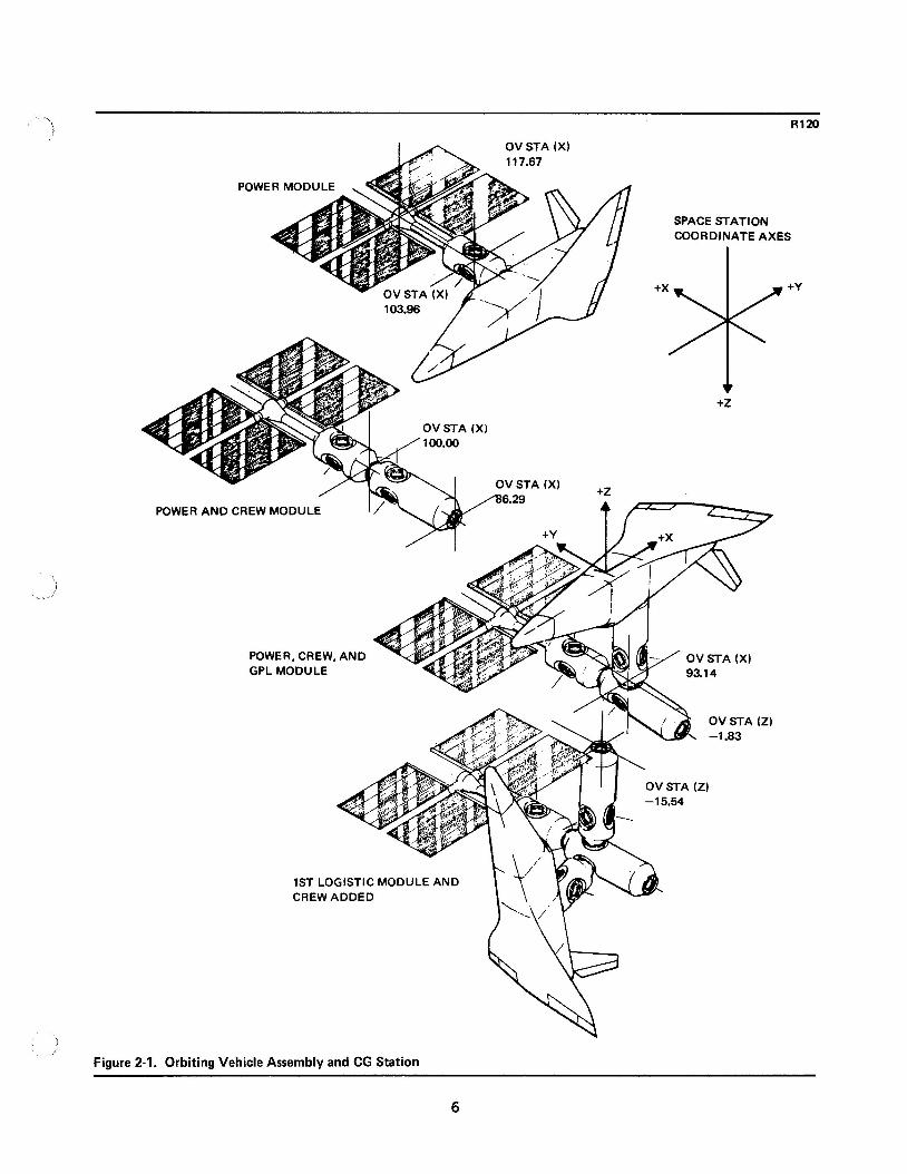
Table 2- 1 i s a sequence mass p rope r t i e s summary s tar t ing with the Power
Module, then the Crew Module, the G P L Module, and the Logistic Modules.
The f i r s t Logistic Module supplies expendables for a three-man c r e w and
associated c r e w manning provisions.
second Logistic Module and two additional c rewmen (Figure 2- 1).
This is followed 30 days later with a
i The longitudinal cg excursion l imi t s as defined by the Orbiter a r e noted on
Figure 2-2.
(6 inches) about the Orbi ter ca rgo bay center l ine.
GPL Modules exceed the l a t e ra l and ver t ica l limits.
minor problem and during the next report ing period the internal provis ions
will be relocated to conform t o the limits.
The l a t e ra l ( Y ) and ver t ica l ( Z ) ax is limits are *to. 15 m e t e r
Currently, the Crew and
This is considered a
4

r-- .n
2 P OI
0I P .n* 3
3 3
W W 0 .-I 3
P
i m
OI r- d
.n < m N
3
m .n W
.n d 2
W
r- m 3
I-
d m
OI W N
0 m 2
I
0
.$ 2
3 N' 6 d
.n P W
W N
1 W
3
d a-
5
I A OV STA (XI
,i . .-
POWER MODU
SPACE STATION COORDINATE AXE
+x* +Z
POWER AND CREW MODUL
POWER, CREW, AND GPL MODULE
IST LOGISTIC MODULE AND CREW ADDED
:S
+Y
Figure 2-1. Orbiting Vehicle Assembly and CG Station
6

~ _ _
I R120
GPL MODULE
CREW MODULE NO. 1
POWER MODULE NO. 1
I I I I I I I I I I 0 2 4 6 8 10 12 14 16 17.68
SPACE STATION MODULAR CG STATIONS (METERS) I
LONGITUDINAL CG ENVELOPE (X) (ON ORBIT)
1,200 1,300 1.400 1,500 1.600 1,700 1,800 1.900
15 X 60 FT PAYLOAD ENVELOPE
1,865 I
1,076
1
Figure 2-2. Launched Space Station Module CG's and Orbiter-Imposed Limits
7
Section 3
BASELINE SPACE STATION MODULE CONFIGURATION
The mass proper t ies presented in this section a r e m o r e detailed than those
of the previous sections. They include only the ISS modules: Power, Crew,
and GPL.
represents the fo rma l documentation i n accordance with MIL-M-38310A.
The Logistic Module is summar ized in Section 4. This section
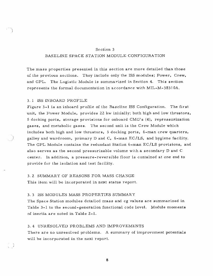
3. 1 ISS INBOARD PROFILE
Figure 3-1 is a n inboard profile of the Baseline ISS Configuration.
unit, the Power Module, provides 22 kw initially; both high and low thrus tors ,
5 docking ports , s torage provisions fo r onboard CMG's (4), repressur iza t ion
gases , and metabolic gases .
includes both high and low thrus tors , 5 docking ports, 6-man crew quar te rs ,
) galley and wardroom, p r i m a r y D and Cy 6-man EC/LS, and hygiene facility.
The f i r s t
The second unit is the Crew Module which
The GPL Module contains the redundant Station 6-man EC/LS provisions, and
a l so s e r v e s as the second pressur izable volume with a secondary D and C
center.
provide for the isolation and tes t facility.
In addition, a p re s su re - r eve r s ib l e floor is contained a t one end to
3 . 2 SUMMARY OF REASONS FOR MASS CHANGE
This i tem will be incorporated in next s ta tus report .
3 . 3 ISS MODULES MASS PROPERTIES SUMMARY
The Space Station modules detailed mass and cg values a r e summarized in
Table 3-1 to the second-generation functional code level. Module moments
of iner t ia a r e noted in Table 2-1.
3 . 4 UNRESOLVED PROBLEMS AND IMPROVEMENTS
There a r e no unresolved problems. A summary of improvement potentials
will be incorporated in the next report .
8

1 c
9

3.
5
3. H p: w
m
7 8 cc)
0 0
0
0 0
0
0 m d
0 I m m
0 m m
0 0
0
0 0
0
0 m .n
0 I m m
0 m m
0 0 0 0
0 0
0 0 0 0
0 0
0 0 0 0
d m
* O N m -tu) 3
m m 01 - 2
: 0
0.
N d
0
W
c? m
0. 0 0.
c-
0 m .- 0
0. 0 N
0
N m
c'
c 0 * c'
.n 0
d
3 m 0
0
0 c N
m
0 m N
m-
N m r- 0 0 3 e N N * N 0 0 - 0 0
r i d dc; A N d . . - 3
c' m e $ 4
10
I '.. j
3 . 5 INVENTORY O F FLUIDS AND PROPELLANTS LOADED
This data i s noted in the pertinent subsys tems and will be assembled into a
separa te table for the next repor t .
11

Section 4
BASELINE LOGISTIC MODULE CONFIGURATION
The Baseline Logistic Module contains no provisions for the crew, which is
supplied by the Shuttle Orbiter.
to the Station as it contains no onboard propulsion system. This section
represents the formal documentation i n accordance with MIL-M-383 1 OA.
The Logis t ic Module is a l so d i rec t docked
4 . 1 INBOARD PROFILE
An inboard profile of the Logistic Module will be included in the next report .
Basically, i t is 8. 5 m e t e r s (28 f ee t ) in length with neuter docking a t each
end.
4 . 2 SUMMARY O F REASONS FOR MASS CHANGE f This is the f i r s t reporting and, therefore , not applicable.
4 . 3 LOGISTIC MODULE MASS PROPERTIES SUMMARY
Table 4-1 is a par t ia l mass proper t ies s u m m a r y of the Logistic Module and
the cargo requirements fo r the f i r s t logistic launch.
as logistic options a r e defined as i tems required aboard the Station for manned
operation and contingency backup provisions.
a re CMG's, furnishings, and a repressur iza t ion charge. The 30-day column
includes the crew and subsystem expendables such as propellant, food, and
metabolic oxygen.
together with the additional expendables of 90 m a n days (3 m e n x 30 days)
for the logistic cycle, they total 5, 076 kg (11, 190 lbm).
339 kg mass of 3 crewmen.
(6,497 lbm), and the combination of module and cargo is 8, 023 kg (17,686 lbm),
well below the 9, 072 kg (20, 000 lbm) target .
Those i tems noted
Examples of the fixed i tems
It should be noted that if a l l these i tems a re summed
This includes the
The logistic module has a mass of 2, 947 kg
12

i
d
U
13

'1 4 . 4 UNRESOLVED PROBLEMS AND IMPROVEMENTS
There a r e no unresolved problems.
i n next repor t .
Improvement potentials will be discussed
4 . 5 INVENTORY OF FLUIDS AND PROPELLANTS LOADED
This data is included in the pertinent subsystem, but will be presented in
g rea t e r detai l in la te r r epor t s .
c
14
g 5301 Bolsa Avenue, Huntington Beach, CA 92647