![Human Arm Imitation · Human-robot skeleton mapping Robot Joint Angles D-H Parameters [2] Human Arm Robot Arm References [2] [4] Industrial Robots can now be trained and controlled](https://static.fdocuments.us/doc/165x107/5f76b9ded7aa2d6f12317b91/human-arm-imitation-human-robot-skeleton-mapping-robot-joint-angles-d-h-parameters.jpg)
Hydraulic Robot Arm Assembling Instructions
11
Hydraulic Robot Arm Assembling Instructions Robot Arm Screw Guide: (1:1) Nut Nyloc Nut Screws, nuts and nyloc nuts are given in the pictures.
Transcript of Hydraulic Robot Arm Assembling Instructions
Hydraulic Robot Arm Assembling Instructions Robot Arm Screw Guide:
(1:1)
Nut Nyloc Nut Screws, nuts and nyloc nuts are given in the pictures.
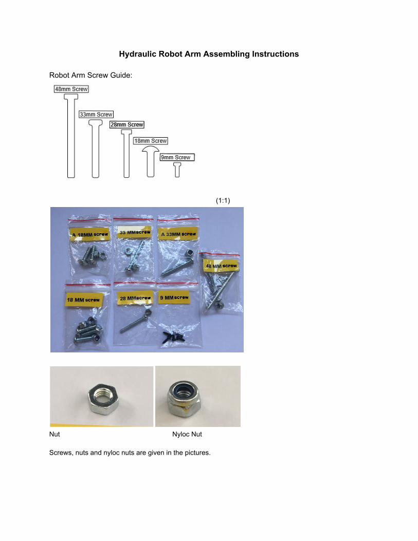
1. Syringe head, left and right robot arm’s gripper bases are assembled with 18 mm screw and nyloc nut.
2. Grippers and gripper bases are assembled into the first set of holes with 18mm screws and nyloc nuts.
3. Top body parts are assembled to the second set of holes of grippers with A 18mm screws and nuts.
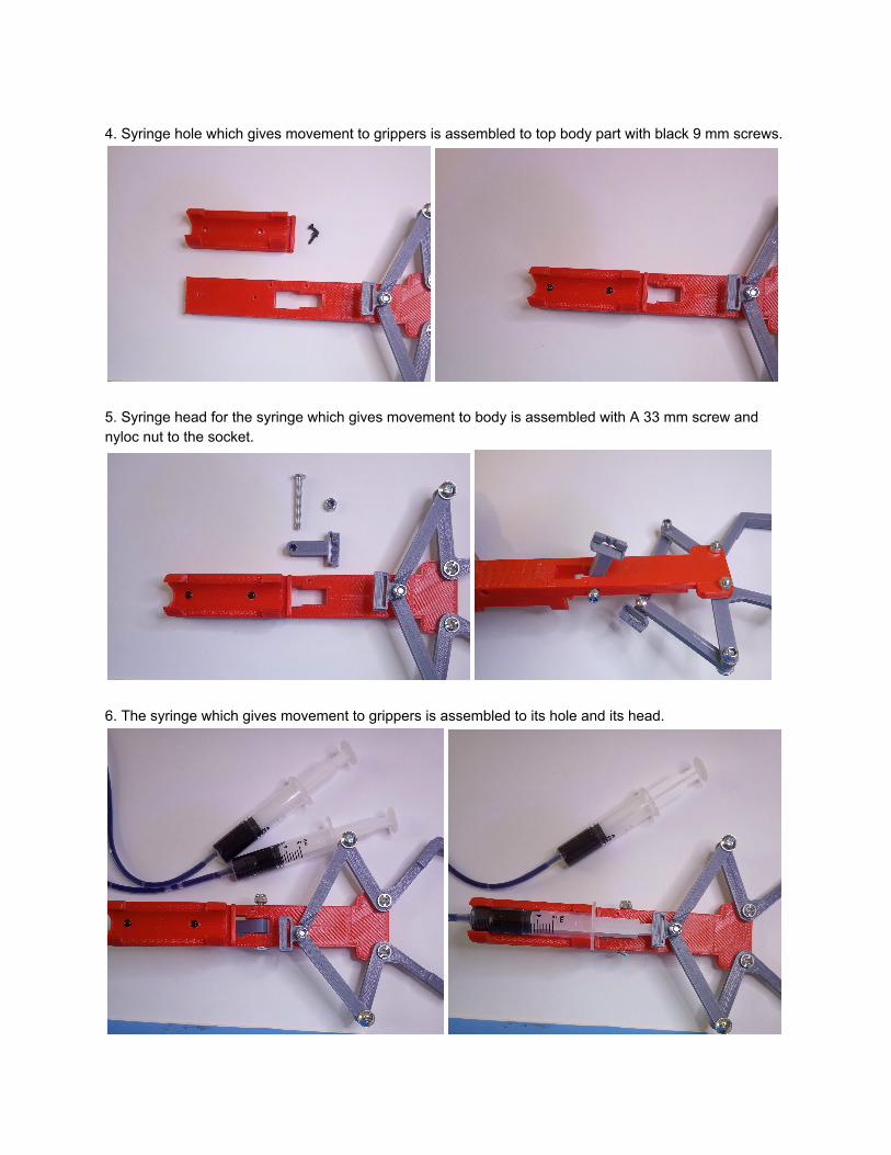
4. Syringe hole which gives movement to grippers is assembled to top body part with black 9 mm screws.
5. Syringe head for the syringe which gives movement to body is assembled with A 33 mm screw and nyloc nut to the socket.
6. The syringe which gives movement to grippers is assembled to its hole and its head.
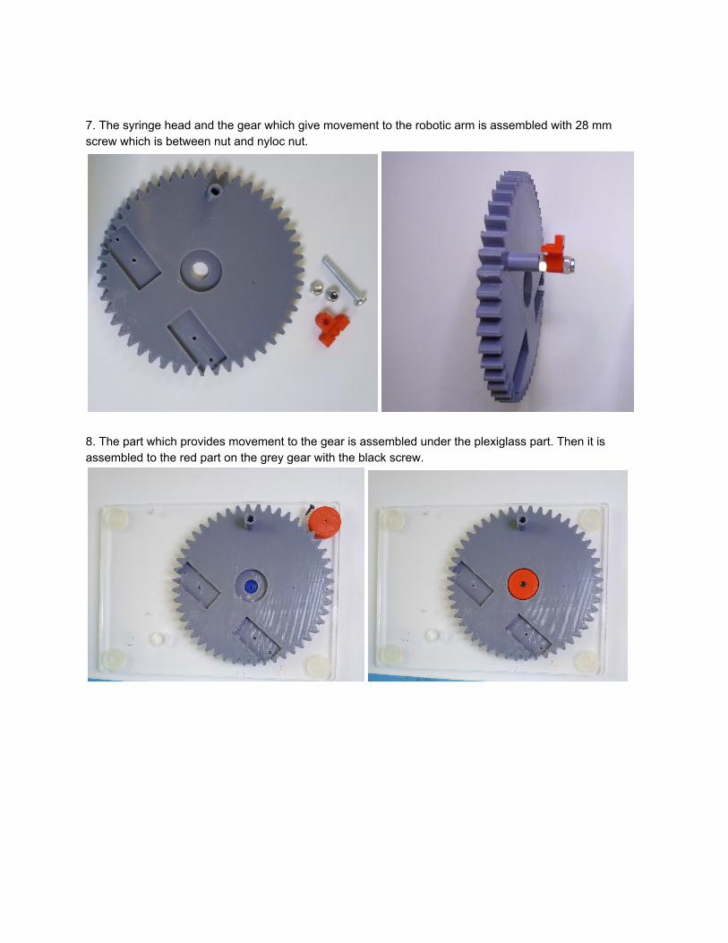
7. The syringe head and the gear which give movement to the robotic arm is assembled with 28 mm screw which is between nut and nyloc nut.
8. The part which provides movement to the gear is assembled under the plexiglass part. Then it is assembled to the red part on the grey gear with the black screw.
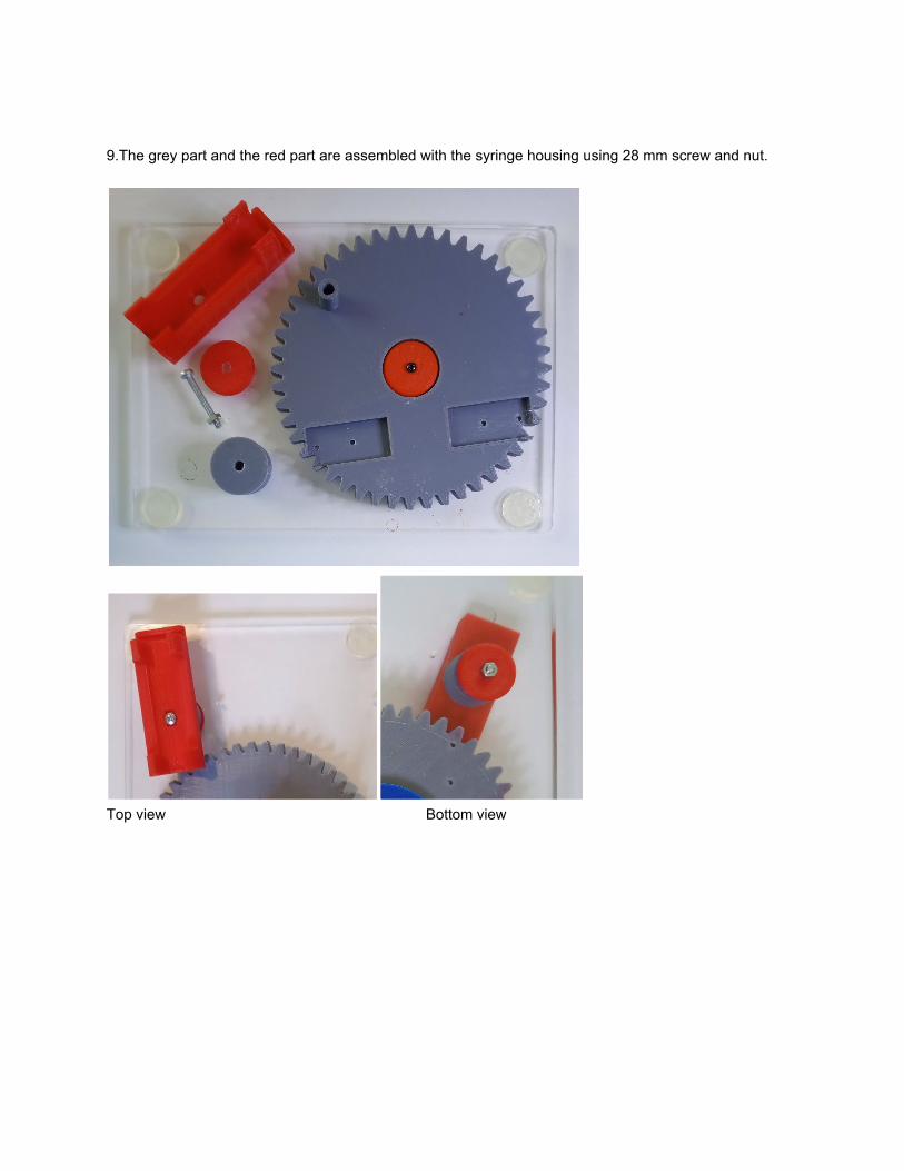
9.The grey part and the red part are assembled with the syringe housing using 28 mm screw and nut.
Top view Bottom view
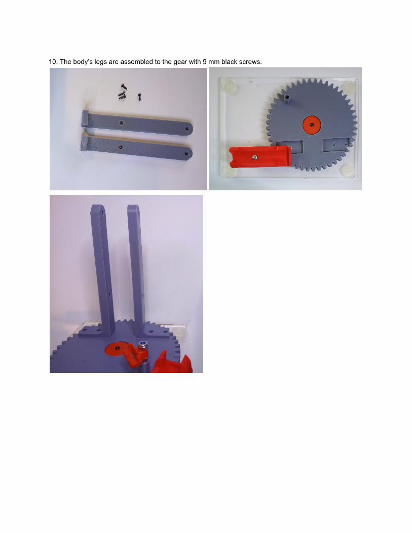
10. The body’s legs are assembled to the gear with 9 mm black screws.
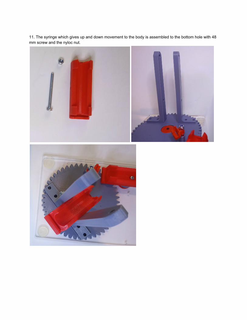
11. The syringe which gives up and down movement to the body is assembled to the bottom hole with 48 mm screw and the nyloc nut.

12. In this stage, the syringes are assembled to syringe housings as seen in the pictures..
13.Top hole of the legs is assembled to the top body part with 48 mm screw and the nyloc nut.
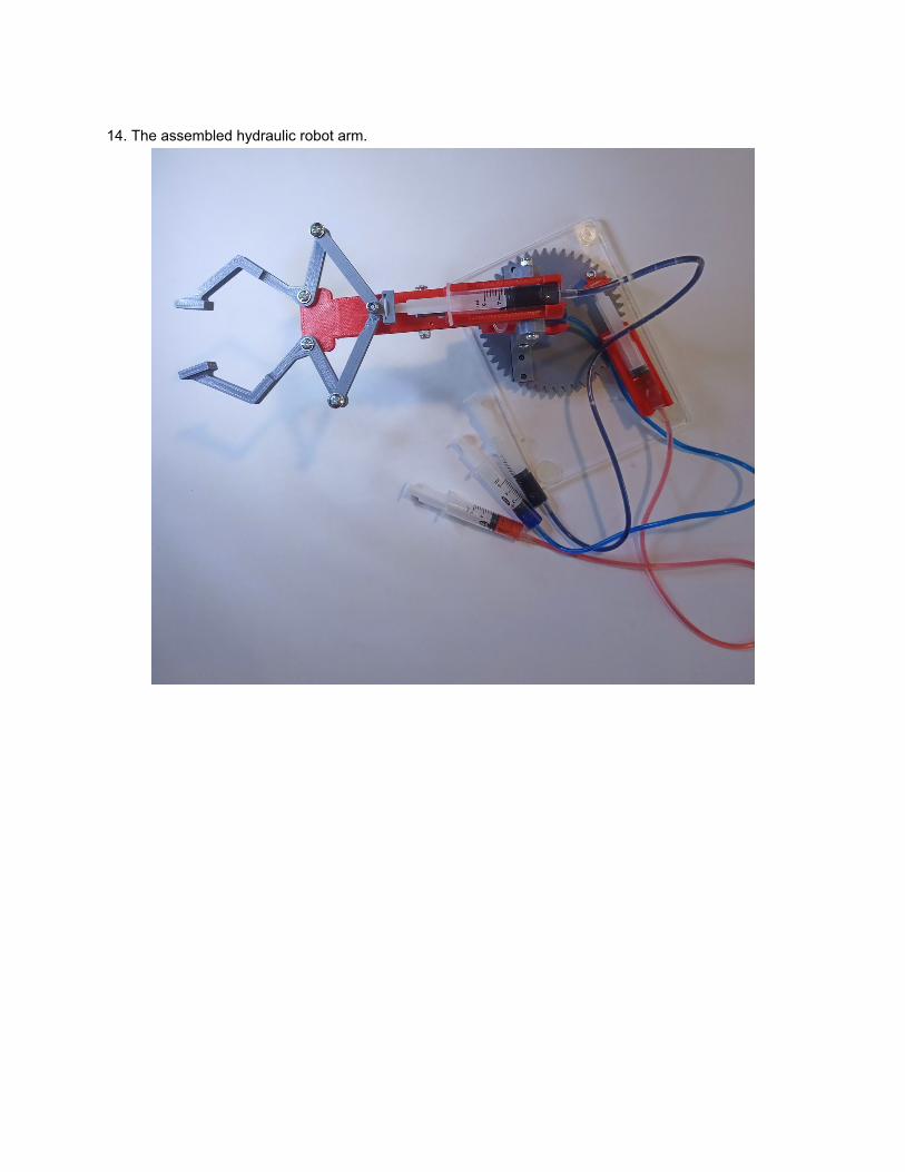
14. The assembled hydraulic robot arm.
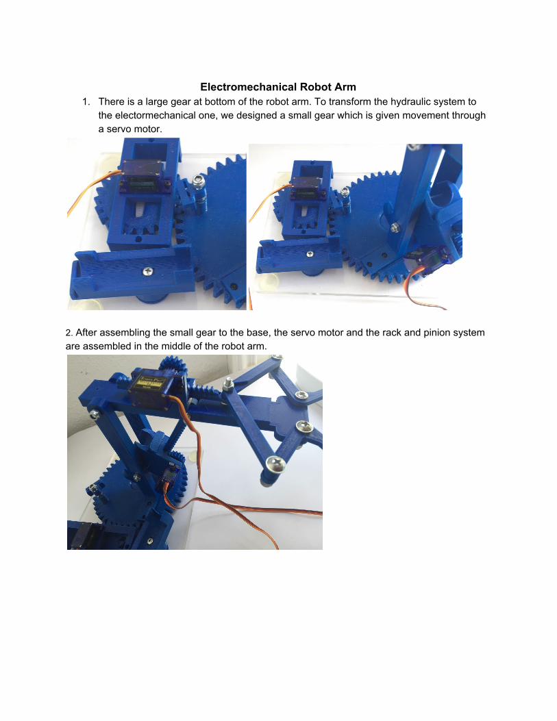
Electromechanical Robot Arm
1. There is a large gear at bottom of the robot arm. To transform the hydraulic system to the electormechanical one, we designed a small gear which is given movement through a servo motor.
2. After assembling the small gear to the base, the servo motor and the rack and pinion system are assembled in the middle of the robot arm.
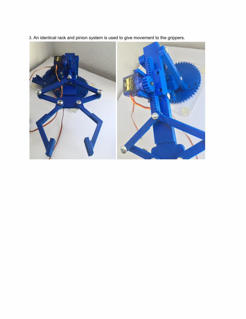
3. An identical rack and pinion system is used to give movement to the grippers.