
Opto-pneumatic control robot arm
6
110 Opto-pneumatic control robot arm Keijiro YAMAMOTO a) and Osamu OYAMA b) a) Kanagawa Institute of Technology ,1033 Shimoogino, Atsugi-shi,243-02,Japan b) Meiji University ,1-1-1 Higashimita,Tama-ku, Kawasaki-shi,214,Japan ABSTRACT Intending to explore the possibility of the optical control robot without interposing any electrical signal,pneumatic control robot arm controlled with photofluidic interface was developed.The interface employs a light absorbing nozzle wall in a laminar proportional fluid amplifier. The fluidic output signal of the interface was amplified by a three-stage laminar proportional amplifier gain block. Robot arm has two members and two joints moved by pneumatic rotary actuators. A membrane type booster amplifier with three staged nozzle-flapper values was used to amplify the power of the output signal of the gain block so far as enough to drive the rotary actuators. Two control methods, such as proportional control employing integration compensa- tion and model reference adaptive control were applied and the com- parison of the suitability of these control methods was made. KEYWORDS Opto-fluidic interface, Robot arm, Pneumatic actuator, Laminar propor- tional amplifier, Membrane type amplifier INTRODUCTION For industrial applications of robots, an optical control offers intrinsic safety, electrical noise immunity, first response, compact low weight devices. Since optical power sources, fiber transmission lines, and optical connector technology are now well developed there seems a good case for investigating the practical application of optical control of robotics. In order to keep the merits of optical control, photofluidic control devices without any mechanical moving and electrical control parts are indispensable elements. For realizing such photofluidic control devices, appropriate corn- bination technique of the ther- modynamic conversion of optical energy to fluid energy and a high sensitivity laminar fluidic amplifier are necessary. There are two conversion methods, one is the combination of a laminar proportional amplifier Fluid Power. Edited by T. Maeda.(C) 1993 E & FN Sport. ISBN 0419 19100 3.
Transcript of Opto-pneumatic control robot arm
110
Opto-pneumatic control robot arm
Keijiro YAMAMOTO a) and Osamu OYAMA b)
a) Kanagawa Institute of Technology ,1033 Shimoogino,Atsugi-shi,243-02,Japan
b) Meiji University ,1-1-1 Higashimita,Tama-ku,Kawasaki-shi,214,Japan
ABSTRACT
Intending to explore the possibility of the optical control robotwithout interposing any electrical signal,pneumatic control robot armcontrolled with photofluidic interface was developed.The interfaceemploys a light absorbing nozzle wall in a laminar proportional fluidamplifier. The fluidic output signal of the interface was amplified bya three-stage laminar proportional amplifier gain block. Robot arm hastwo members and two joints moved by pneumatic rotary actuators. Amembrane type booster amplifier with three staged nozzle-flappervalues was used to amplify the power of the output signal of the gainblock so far as enough to drive the rotary actuators. Two controlmethods, such as proportional control employing integration compensa-tion and model reference adaptive control were applied and the com-
parison of the suitability of these control methods was made.
KEYWORDS
Opto-fluidic interface, Robot arm, Pneumatic actuator, Laminar propor-tional amplifier, Membrane type amplifier
INTRODUCTION
For industrial applications ofrobots, an optical control offers
intrinsic safety, electricalnoise immunity, first response,compact low weight devices. Sinceoptical power sources, fiber
transmission lines, and opticalconnector technology are now welldeveloped there seems a good casefor investigating the practical
application of optical control ofrobotics.In order to keep the merits of
optical control, photofluidiccontrol devices without anymechanical moving and electrical
control parts are indispensableelements.For realizing such photofluidiccontrol devices, appropriate corn-bination technique of the ther-modynamic conversion of optical
energy to fluid energy and a highsensitivity laminar fluidicamplifier are necessary.There are two conversion methods,
one is the combination of alaminar proportional amplifier
Fluid Power. Edited by T. Maeda.(C) 1993 E & FN Sport. ISBN 0419 19100 3.
756
(LPA) and a photo-acoustic cellas the control port of the LPA[1], the other is the temperaturecontrol of the power jet's bound-ary layer in which light isfocused onto the base plate ofthe LPA [2].This paper describes the evalua-tion of a novel photofluidic in-terface in which light il-luminates the light absorbingside wall of the supply nozzle ofthe LPA and the feasibility ofthe photo-pneumatic control robotarm which consists of thephotofluidic interface, a LPAgain block,a proportional gainmodule, a booster amplifier andthe robot arm with pneumaticrotary actuators.
PHOTOFLUIDIC CONTROL DEVICE
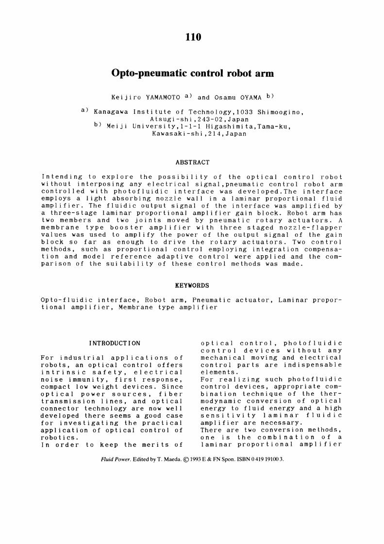
The photofluidic control devicehad two sections, a photo-fluidicinterface and a pre-amplifier(Fig.1). The photo-fluidic inter-face employed the LPA in whichthe end section of the opticalfiber constructed the side wallof the supply nozzle on whichcarbon black was deposited as alight absorber.The beam from a laser diode (Warelength 810nm, Operating current102mA at Light output 40mW) wasfocused by a focusing lens to a0.5mm diameter spot on the inputend section (0.5 mm diameter) ofthe optical fiber. The side wallof the supply nozzle absorbs thelight energy from the laser beamtransmitted through the fiber andtransfers it to the boundarylayer of the nozzle flow contactto the heated side wall. The tem-
perature distribution of thenozzle flow becomes unsymmetri-cal, then the supply jet deflectsto the direction of rather highervelocity boundary layer.The photofluidic interface LPAwas a custom design with 0.38mmthroat width and a 1.3 aspectratio.The preamplifier was composed oftwo cascaded high impedanceLPA's, i.e., the LPA with 0.38mmthroat width and 1.3 aspect ratioand the LPA with 0.76mm throatwidth and 0.65 aspect ratio.
Fig.1 Configuration of opto-fluidic control device
POWER AMPLIFIER
The photofluidic control devicewas a high impedance, small sig-nal device which is not capableof delivering sufficient power tomove an actuator. The controldevice output was, therefore,amplified by a low impedancethree-stage proportional gainmodule, the output of the gainmodule was,then, amplified by thetwo cascaded booster amplifierswhich was used to driveapneumatic rotary actuator.The three-stage proportional gainmodule was composed of three cas-caded proportional amplkfierswith a 1.5mm throat width and a1.33 aspect ratio. The impedanceof the gain module was low enoughto deliver sufficien4 power todrive the booster amplifier with
757
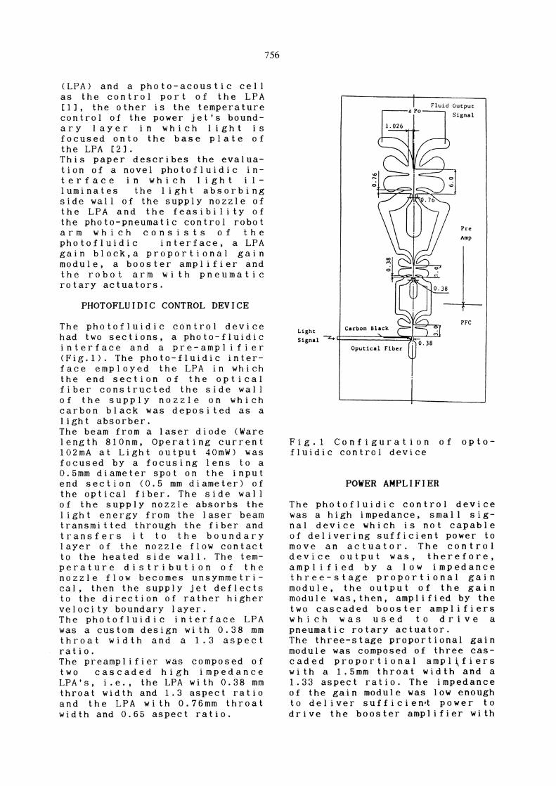
the volume of 1000 cubic mil-limeters.The booster amplifier consisted
of a pilot nozzle-flapper typevalve followed by a main nozzle-flapper type valve as shown inFigure 2. The diameters of the
nozzles of the pilot and of themain valves were 1.0mm and 1.0mm,respectively and that of themembranes of them were 35mm and30mm, respectively.
ROBOT ARM
Robot arm had two members and two
joints moved by pneumatic rotaryactuators. The lengths andweights of the members were 260mmand 600g, and 150mm and 230g,respectively as shown in Figure
3.The pneumatic rotary actuatorswere a custom design with a 50mmdiameter and 60mm thickness. The
threshold value of pressure todrive the rotary actuator was100kPa.
The system was controled with on-off optical signal. Two controlmethods were tested and compared.First method was proportionalcontrol with integration compen-
sation and the second one wasmodel reference adaptive control.In the second method, controllinginput was calculated by Equation1.
(1)
Signal vector was determined byEquation 2.
(2)
Error signal is presented by
Equation 3.
(3)
Controllable parameter was ad-justed by Equation 4.
(4)
Fixed gain law was adopted in
this method.
Fig.2 Schematic of boosteramplifier
Fig.3 Schematic of robot arm

758
EXPER I MENTAL RESULTS
Differential blocked output pres-sure of the photofluidic controldevice was measured varying theoptical power. These measurementswere made operating at five com-
binations of the supply pressuresof the interface and
preamplifiers as summarized inFigure 4. As shown in Figure 4,the photofluidic control device
response was linear at optical
power above 13mW.The control device could be
characterized by an opto-fluidic
gain of 2.22Pa per mW at thesupply pressures,Ps1 = 200Pa, Ps2= 200Pa and Ps3 = 400 Pa (0.21Pa
per mW at the supply pressures,100, 100, 100 Pa respectively)for up to 30 mW of optical power.The frequency response of thecontrol device was measured byhaif-sinusoidally modulating the
input signal to the laser diodedriving circuit and observing the-3dB point . The control device3dB cutoff point was above 100Hzwhile driving a blocked load of
50 cubic millimeters. Thebandwidth was almost independentof changes in the supply pressureand optical power.The three-stage proportional gain
module was operated at the supply
pressure of 500, 700 and 1000Pa,and had a pressure gain of 17delivering an blocked differen-tial output pressure of 360Pa.
The amplifying chracteristics ofthe booster amplifier is shown inFigure 5. The supply pressure Psb
was chosen as the operating
parameter of the boosteramplifier. The output pressurewas measured with blocked load,
and the output flow rate wasmeasured with no load resistance.The booster amplifier could becharacterized by the pressure
gain of 1300 with the threshholdinput pressure of 400Pa and the
maximum output flow rate of0.0006m /s. The output power ofthe booster amplifier was enoughto drive a commercial pneumatic
rotary actuator.
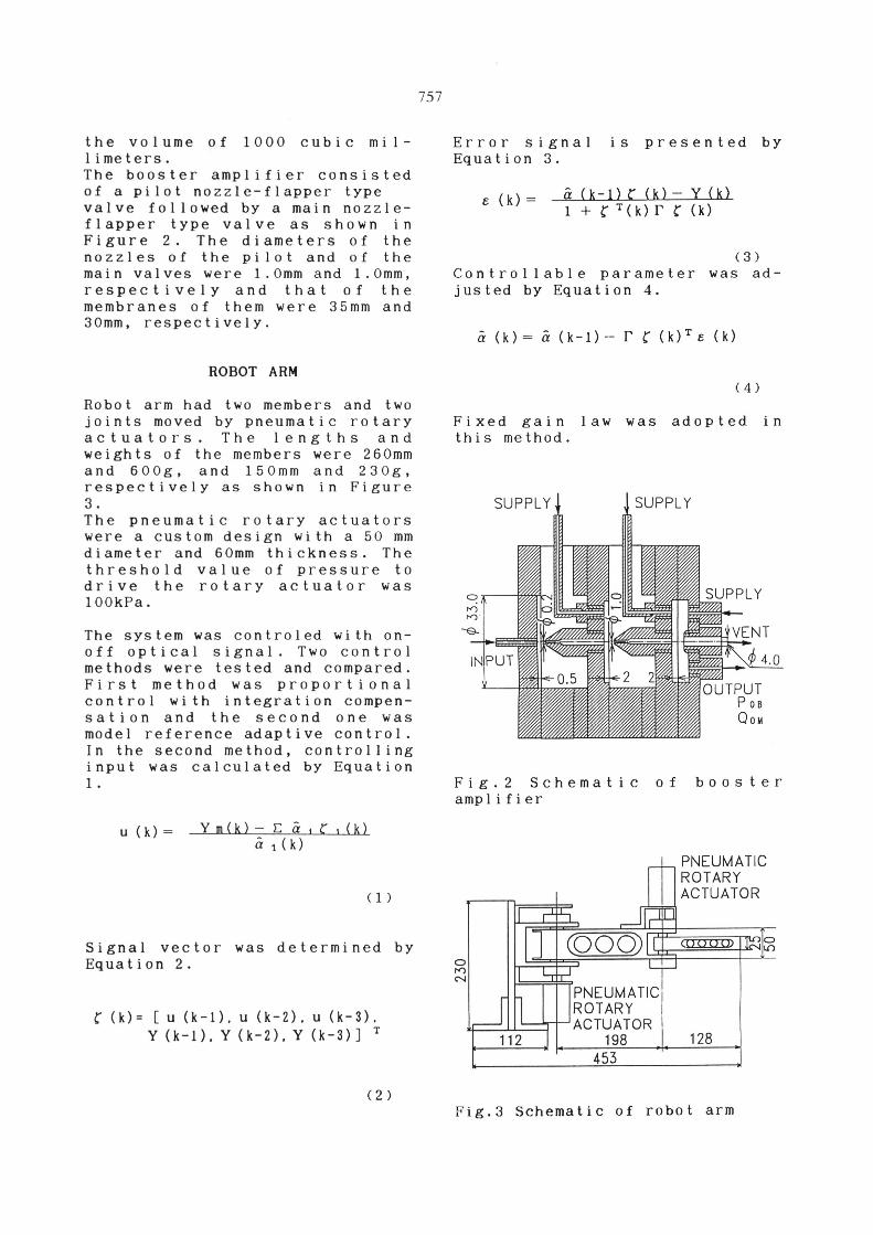
The step responses of the robotarm are shown in Figures 6(a)-(e). These measurements were madewith a rotary potentiometer forangle.
Figures 6(a) and (b) show theresponses in case of the propor-tional control with integretioncompensation. The difference insettling times is due to the dif-ference in integration action
times. Figures 6(c), (d) and (e)
Fig.4 Conversion characteristics
of opto-fluidic control device
Fig.5 Booster amplifier gain
characteristics
759
show the responses of the modelreference adaptive control withthe different gains. As shown inFigures 6(c) and (e), too smallor large gains cause vibration.
CONCLUSIONS
The robot arm described abovesuccessfully demonstrated thatthe optofluidic control devicecan be combined with fluidicamplifiers and nozzle-flappertype booster amplifiers to buildan actuator system. The optother-mal technique have the advantageof simplicity and performance.A simple and fast acting con-verter system has been developedthat is capable of directly con-trolling commercially availablepneumatic actuators.The key was operating the
photofluidic interface and thepreamplifier in the laminar flowregime so that the signal waslarge enough for turbulent poweramplifier to raise the powerlevel of the signal without sig-nificantly degrading a systemsignal-to-noise ratio.The tested system was a bread-board system bui l t with discretecomponents which were connectedwith small manifold blocks. Thiswas adequate for demonstratingsystem operation but had a slowsignal propagation time due tolarge volumes and long signalpath lengths. In future applica-tions, the booster amplifier canbe redesigned as a modular com-
ponent to improve overallbandwidth. Further improvementsof the device are being studied.
ACKNOWLEDGMENTS
The authors are grateful toMr.Kazushige Yokota, Mr.TooruYamahashi and Mr.Masakazu Katsuand Mr.Takeshi Oosawa, graduatestudents o f Meiji University forthe experiments. The authors alsothank CKD Co. Ltd . for thefabrication of laminar propor-tional amplifiers.
(a)
(b)
(c)
(d)
(e)
Fig.6 Step responces of arm

760
REFERENCES
1 J. O. Gurney, Trans. ASME, J. Dyn.Syst.Meas.& Cont.,106 (1984) 90.K. Yamamoto, Trans.SICE, Japan, 27-12 (1991) 1406.
2 B. Hockaday, W. Glomb, K. Taylor and J. Waters, J. Fluid Control,16-2/3 (1986) 17.S. Dohta and T. Takakamori, Trans. SICE, Japan, 26-5 (1990) 595.
S. Dohta, M. Tohkai and T. Takamori, ibid, 26-7 (1990) 780.


