High rise building construction
74
BY- DIGVIJAY RAMTEKE PRASHANT DEVDA HIGH RISE BUILDING CONSTRUCTION
-
Upload
construction-tech-and-mgmt-vnit-nagpur -
Category
Technology
-
view
1.486 -
download
31
Transcript of High rise building construction
BY-DIGVIJAY RAMTEKEPRASHANT DEVDA
HIGH RISE BUILDING CONSTRUCTION

NEED OF HIGH RISE BUILDING:
High rise buildings are becoming prominent these days due to following reasons scarcity of land increasing demand for business and residential space economic growth technological advancement innovations in structural systems desire for aesthetics in urban setting cultural significance and prestige human aspiration to build higher

INTRODUCTION AND DEFINITIONHigh rise is defined differently by different bodies.
Emporis standards- “A multi-story structure between 35-100 meters tall, or a building of unknown height from 12-39 floors is termed as high rise.
The International Conference on Fire Safety – "any structure where the height can have a serious impact on evacuation“
Massachusetts, United States General Laws –A high-rise is being higher than 70 feet (21 m).
Building code of Hyderabad,India- A high-rise building is one with four floors or more, or one 15 meters or more in height.National Building Code (Part 4) – Fire and Life Safety all buildings 15m and above in height shall be considered as high rise buildings.

TYPES OF FOUNDATION
a) Shallow Foundation System i) Spread Foundation
ii) Mat / Raft Foundation
b) Deep Foundation Systemi) Pile iii) Diaphragham wallii) Pile walls iv) Caissons

Spread Foundation
Spread footings may be built in different shapes & sizes to accommodate individual needs such as the following: a) Square Spread Footings / Square Footings b) Rectangular Spread Footings c) Circular Spread Footings d) Continuous Spread Footings e) Combined Footings f) Ring Spread Footings

a) Square Spread Footings / Pad Foundation - support a single centrally located column - use concrete mix 1:2:4 and reinforcement - the reinforcement in both axes are to resist/carry tension loads.
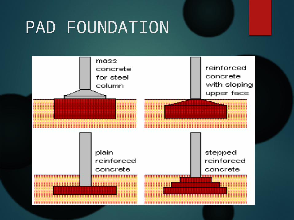
PAD FOUNDATION
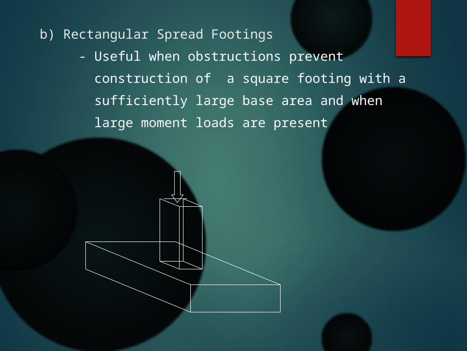
b) Rectangular Spread Footings - Useful when obstructions prevent construction of a square footing with a sufficiently large base area and when large moment loads are present

c) Circular Spread Footings - are round in plan view - most frequently used as foundation for light standards, flagpoles and power transmission lines.

d)Continuous Spread Footings / Strip Foundation - Used to support bearing walls
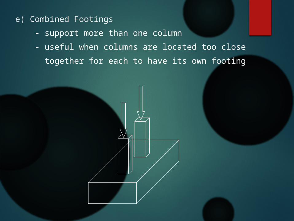
e) Combined Footings - support more than one column - useful when columns are located too close together for each to have its own footing
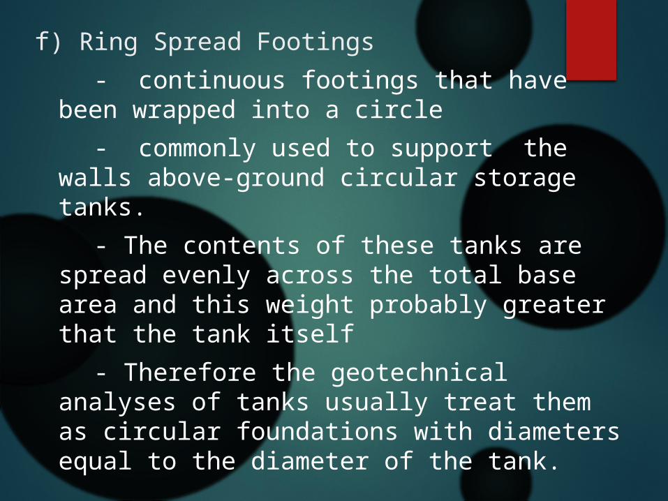
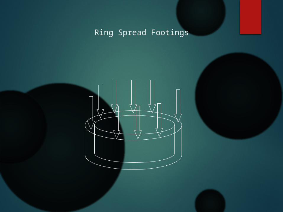
f) Ring Spread Footings - continuous footings that have been
wrapped into a circle - commonly used to support the walls
above-ground circular storage tanks. - The contents of these tanks are spread
evenly across the total base area and this weight probably greater that the tank itself
- Therefore the geotechnical analyses of tanks usually treat them as circular foundations with diameters equal to the diameter of the tank.
Ring Spread Footings
RAFT FOUNDATION A foundation system in which essentially the entire building is placed on a large continuous footing. It is a flat concrete slab, heavily reinforced with steel, which carries the downward loads of the individual columns or walls. Raft foundations are used to spread the load from a structure over a large area, normally the entire area of the structure.
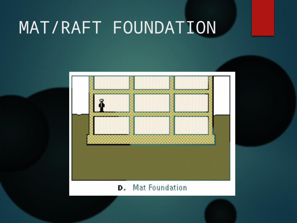
MAT/RAFT FOUNDATION

DEEP FOUNDATION
Extend several dozen feet below the building a) Piles
b) Piersc) Caissonsd) Compensated Foundation
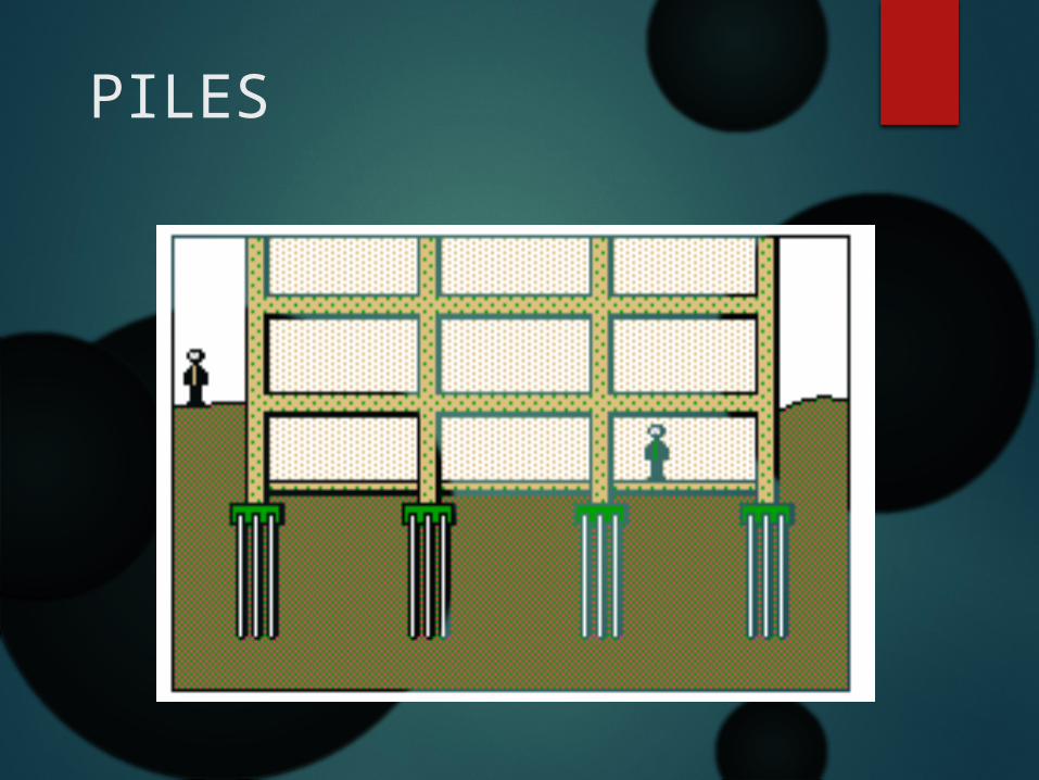
PILES
LOAD CAN BE TRANSFERRED BY PILE TO THE GROUND BY 2 WAY THAT IS:
a) End Bearing Piles OR - Pile will transmit load into the firm soil layer of
the ground such as rock, gravel, very dense sand
b) Friction Piles - Pile transmit the load from the structure to the
penetrable soil by means of skin friction or cohession between the soil & the embedded surface of the pile.

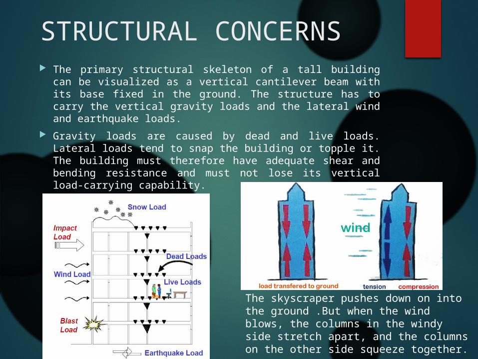
STRUCTURAL CONCERNS The primary structural skeleton of a tall building can be
visualized as a vertical cantilever beam with its base fixed in the ground. The structure has to carry the vertical gravity loads and the lateral wind and earthquake loads.
Gravity loads are caused by dead and live loads. Lateral loads tend to snap the building or topple it. The building must therefore have adequate shear and bending resistance and must not lose its vertical load-carrying capability.
The skyscraper pushes down on into the ground .But when the wind blows, the columns in the windy side stretch apart, and the columns on the other side squeeze together.
CLASSIFICATION OF TALL BUILDING STRUCTURAL SYSTEMS Can be classified based on the structural material used such as
concrete or steel Structural systems of tall buildings can also be divided into two
broad categories: 1)INTERIOR STRUCTURES 2)EXTERIOR STRUCURES This classification is based on the distribution of the components of
the primary lateral load-resisting system over the building. A system is categorized as an interior structure when the major part of the lateral load resisting system is located within the interior of the building. Likewise, if the major part of the lateral load-resisting system is located at the building perimeter, a system is categorized as an exterior structure. It should be noted, however, that any interior structure is likely to have some minor components of the lateral load-resisting system at the building perimeter, and any exterior structure may have some minor components within the interior of the building.
INTERIOR STRUCTURAL SYSTEM
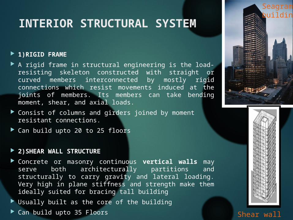
1)RIGID FRAME A rigid frame in structural engineering is the load-resisting
skeleton constructed with straight or curved members interconnected by mostly rigid connections which resist movements induced at the joints of members. Its members can take bending moment, shear, and axial loads.
Consist of columns and girders joined by moment resistant connections.
Can build upto 20 to 25 floors
2)SHEAR WALL STRUCTURE Concrete or masonry continuous vertical walls may serve
both architecturally partitions and structurally to carry gravity and lateral loading. Very high in plane stiffness and strength make them ideally suited for bracing tall building
Usually built as the core of the building Can build upto 35 Floors
Seagram building
Shear wall core

3)OUTRIGGER STRUCTURES
The core may be centrally located with outriggers extending on both sides or in some cases it may be located on one side of the building with outriggers extending to the building columns on the other side
The outriggers are generally in the form of trusses (1 or 2 story deep) in steel structures, or walls in concrete structures, that effectively act as stiff headers inducing a tension-compression couple in the outer columns.
Belt trusses are often provided to distribute these tensile and compressive forces to a large number of exterior frame columns.
An build upto 150 floors
Shangai World financial centre
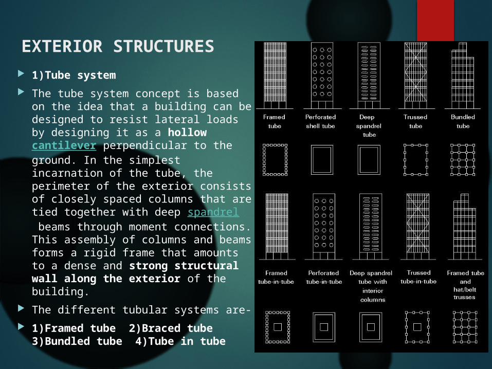
EXTERIOR STRUCTURES 1)Tube system The tube system concept is based
on the idea that a building can be designed to resist lateral loads by designing it as a hollow cantilever perpendicular to the ground. In the simplest incarnation of the tube, the perimeter of the exterior consists of closely spaced columns that are tied together with deep spandrel beams through moment connections. This assembly of columns and beams forms a rigid frame that amounts to a dense and strong structural wall along the exterior of the building.
The different tubular systems are- 1)Framed tube 2)Braced tube
3)Bundled tube 4)Tube in tube
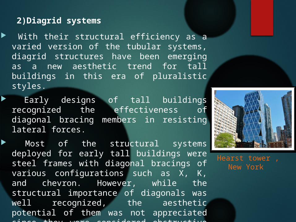
2)Diagrid systems With their structural efficiency as a varied
version of the tubular systems, diagrid structures have been emerging as a new aesthetic trend for tall buildings in this era of pluralistic styles.
Early designs of tall buildings recognized the effectiveness of diagonal bracing members in resisting lateral forces.
Most of the structural systems deployed for early tall buildings were steel frames with diagonal bracings of various configurations such as X, K, and chevron. However, while the structural importance of diagonals was well recognized, the aesthetic potential of them was not appreciated since they were considered obstructive for viewing the outdoors.
Efficiently resists lateral shear by axial forces in the diagonal members but have Complicated joints
Hearst tower , New York

3)Space truss
Space truss structures are modified braced tubes with diagonals connecting the exterior to interior. In a typical braced tube structure, all the diagonals, which connect the chord members – vertical corner columns in general, are located on the plane parallel to the facades.
However, in space trusses, some diagonals penetrate the interior of the building.
4)Exo skeleton structure
In exoskeleton structures, lateral load-resisting systems are placed outside the building lines away from their facades.
Due to the system’s compositional characteristics, it acts as a primary building identifier – one of the major roles of building facades in general cases.
Fire proofing of the system is not a serious issue due to its location outside the building line.
Bank of China, Hong Kong
Hotel de las Atres

5)Super frame structures
Superframe structures can create ultra high-rise buildings upto 160 floors.
Superframes or Megaframes assume the form of a portal which is provided on the exterior of a building.
The frames resist all wind forces as an exterior tubular structure. The portal frame of the Superframe is composed of vertical legs in each corner of the building which are linked by horizontal elements at about every 12 to 14 floors.
Since the vertical elements are concentrated in the corner areas of the building, maximum efficiency is obtained for resisting wind forces.
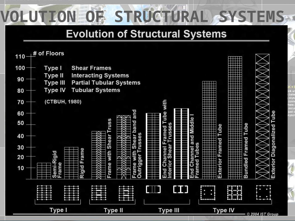
EVOLUTION OF STRUCTURAL SYSTEMS
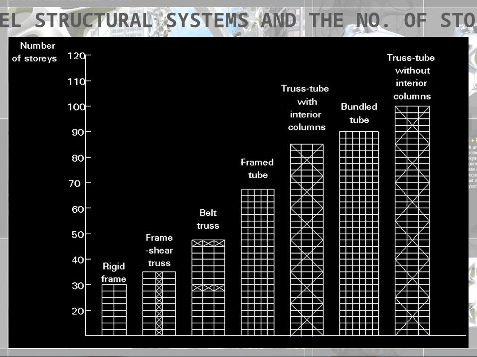
STEEL STRUCTURAL SYSTEMS AND THE NO. OF STOREYS

EXAMPLES OF STEEL STRUCTURAL SYSTEMS
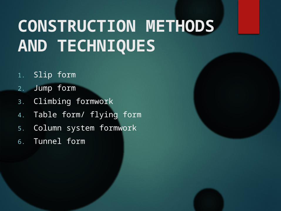
1. Slip form2. Jump form3. Climbing formwork4. Table form/ flying form5. Column system formwork6. Tunnel form
CONSTRUCTION METHODS AND TECHNIQUES

i. Introductionii. Procedureiii. Types of slip formiv. Advantagev. Precautionsvi. Application of slip form
SLIP FORM CONSTRUCTION…

• Slip form construction, or continuously formed construction, is a construction method in which concrete is poured into a continuously moving form.
• Basically, this method involves the continuous placing of concrete in a shallow mould having the same plan as the building to be constructed. This rigid mould, or "slip-form" as it is called, forms the working deck which is jacked slowly upwards at a controlled rate until the required elevation is reached.
INTRODUCTION…
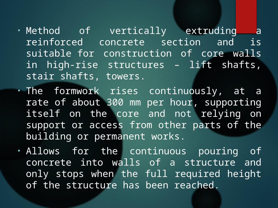
• Method of vertically extruding a reinforced concrete section and is suitable for construction of core walls in high-rise structures – lift shafts, stair shafts, towers.
• The formwork rises continuously, at a rate of about 300 mm per hour, supporting itself on the core and not relying on support or access from other parts of the building or permanent works.
• Allows for the continuous pouring of concrete into walls of a structure and only stops when the full required height of the structure has been reached.
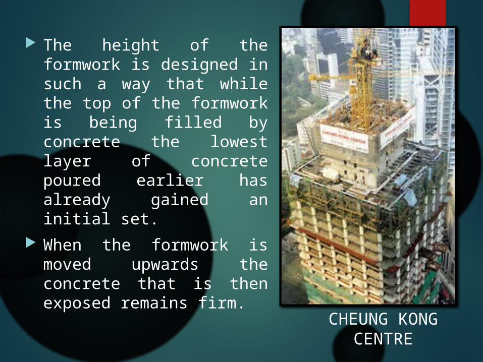
The height of the formwork is designed in such a way that while the top of the formwork is being filled by concrete the lowest layer of concrete poured earlier has already gained an initial set.
When the formwork is moved upwards the concrete that is then exposed remains firm.
CHEUNG KONG CENTRE
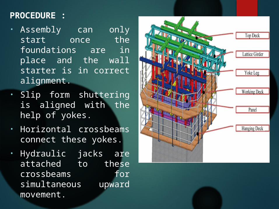
PROCEDURE :• Assembly can only start
once the foundations are in place and the wall starter is in correct alignment.
• Slip form shuttering is aligned with the help of yokes.
• Horizontal crossbeams connect these yokes.
• Hydraulic jacks are attached to these crossbeams for simultaneous upward movement.
• Height of the slip form ranges from 1.1 to 1.5 meters.
• Yokes and crossbeams also used to support the working platform.
• Structure should be rigid and shape maintained at all times.
• Make sure there is no lag or else it prevents the structure from free upward movement
• It is also possible to reduce wall thicknesses .

TYPES OF SLIP FORM CONSTRUCTION
1-VERTICAL SLIP-FORM
In vertical slip forming, the concrete form may be surrounded by a platform on which workers stand, placing steel reinforcing rods into the concrete and ensuring a smooth pour.
Together, the concrete form and working platform are raised by means of hydraulic jacks.
Generally, the slip-form rises at a rate which permits the concrete to harden by the time it emerges from the bottom of the form.
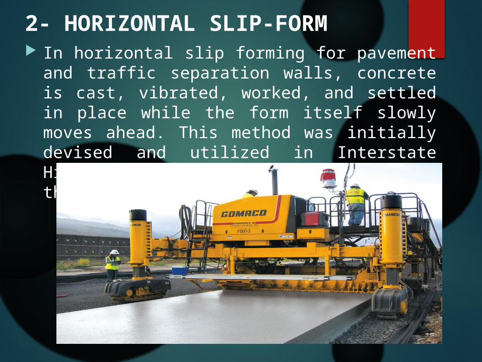
2- HORIZONTAL SLIP-FORM In horizontal slip forming for pavement and traffic
separation walls, concrete is cast, vibrated, worked, and settled in place while the form itself slowly moves ahead. This method was initially devised and utilized in Interstate Highway construction initiated during the 1950s.

• Slip form methods of construction can also be adapted to horizontal structures and are used for paving, canals, and tunneling.
• The technique is more in use for structures that have continuous walls like silos , chimneys, and piers for very tall bridges.
• It has also been successfully used for construction of buildings, although this requires the manner of leaving inserts for openings like doors and windows to be decided well in advance, as well as also any necessary inserts to support floor slabs after the walls are constructed.
3-TAPERED SLIP-FORMING Slip-forming is also used in the construction of conical
chimneys, cooling towers, piers and other tall concrete structures involving constant or changing thicknesses in walls, diameters and/or shapes.
A form is used with sections which overlap so that one gradually slides over the other.
This is commonly done in chimney construction but it is not satisfactory for architectural concrete because the lap shows.
While the tapered slip-forming process is similar to that used on the standard slip-forming, it requires greater attention, contractor experience and expertise ensures the success of such projects.


ADVANTAGES: • A major cost of concrete structure construction is the required
formwork to retain the concrete till it can be safely de-shuttered and be able to support itself and other imposed loads.
• The formwork needs to be continually removed to newer locations and then re-erected.
• Continuous use of manpower and lifting equipment like cranes.• In the case of slip form building, the formwork is erected only
once and remains intact until the entire structure is completed.• Great reduction in the cost of formwork as well as time saving
for re-erection.• Cost effective• The reduction in the movement of formwork and workers also
leads to far more safe working conditions that also make it a major advantage.

PRECAUTIONS• Concrete is continuously protected against loss of
moisture and rapid temperature changes for 7 days• Unhardened concrete is protected from rain and
flowing water• Prevent plastic shrinkage• Plastic cracks are filled by injection of epoxy resin.

CAPITAL GATE- ABUDHABI
BURJ KHALIFA

JUMP FORM Generally, jump form systems
comprise the formwork and working platforms for cleaning/fixing of the formwork, steel fixing and concreting.
Jump form, often described as climbing form. It is suitable for construction of multi-floor vertical concrete elements in high-rise structures, such as shear walls, core walls, lift shafts, stair shafts and bridge pylons.
It is a highly productive system designed to increase speed and efficiency while minimizing labor and time.
PROCESS EFFICIENCY- Fast construction can be achieved by careful
planning of the construction process. Crane availability is critical for normal jump form.
Self-climbing formwork cuts down the requirement for crane time considerably. By allowing the crane to be used for other construction work this may reduce the total number of cranes needed on site.
The formwork is independently supported, so the shear walls and core walls can be completed ahead of the rest of the main building structure. This can help to provide stability to the main structure during its construction and can have the beneficial effect of taking the jump form core off the project critical path.


SAFETY. Working platforms, guard rails, and ladders are built into the
completed units of market-leading formwork systems. Complete wind-shield protection on platform edges is also possible.
Self-climbing formwork systems are provided with integral free-fall braking devices.
The completed formwork assembly is robust and provides a stable working platform.
The reduced use of scaffolding and temporary work platforms results in less congestion on site.
The setting rate of concrete in those parts of the structure supporting the form is critical in determining the rate at which construction can safely proceed.
The repetitive nature of the work means that site operatives can quickly become familiar with health and safety aspects of their job. Formwork suppliers provide materials and resources to help train the labour force.
SUSTAINABILITY FEATURES The formwork system is easy to clean and reuse with
little formwork waste generated compared to traditional formwork.
Climbing formwork systems offer simplicity, safety and cost effectiveness for certain high-rise building structures.
The repetitive nature of the work, combined with the engineered nature of the formwork, allows fine tuning of the construction operations, which in turn leads to minimal concrete wastage.

Many repeated uses of formwork are possible before maintenance or replacement is needed, the number of uses depending on the quality of the surface finish of concrete specified

It is an economical, rapid and accurate method of constructing reinforced concrete, or post-tensioned concrete structures.
At its most basic level, slipforming is a type of movable formwork which is slowly raised, allowing the continuous extrusion of concrete.
CLIMB FORM CONSTRUCTION

Climbing formwork is a special type formwork for vertical concrete structures that rises with the building process. While relatively complicated and costly, it can be an effective solution for buildings that are either very repetitive in form (such as towers or skyscrapers) or that require a seamless wall structure (using gliding formwork, a special type of climbing formwork).
Various types of climbing formwork exist, which are either relocated from time to time, or can even move on their own (usually on hydraulic jacks, required for self-climbing and gliding formworks).
Types of climbing form

Fig.- Climbing formwork on a future residential skyscraper in New Zealand—the whole white upperstructure is actually formwork and associated working facilities.

Climbing formwork (crane-climbing): in this type of climbing formwork, the formwork around the structure is displaced upwards with the help of one or more cranes .once the hardening of the concrete has proceeded far enough. This may entail lifting the whole section, or be achieved segmentally.
Types…
Crane-Climbing formwork: The working platform and the formwork are a unit
Climbing formwork (self-climbing): In this type of formwork, the structure elevates itself with the help of mechanic leverage equipment (usually hydraulic). To do this, it is usually fixed to sacrificial cones or rails emplaced in the previously cast concrete.
Gliding formwork: This type of formwork is similar to the self-climbing type above. However, the climbing process is continuous instead of intermittent, and is usually only interrupted for a very short time (for example to fix the mounting mechanisms to new anchoring points). The advantage is that it will produce seamless structures, but it requires a continuous, uninterrupted process throughout, with serious potential quality and stability problems if the pour has to be stopped
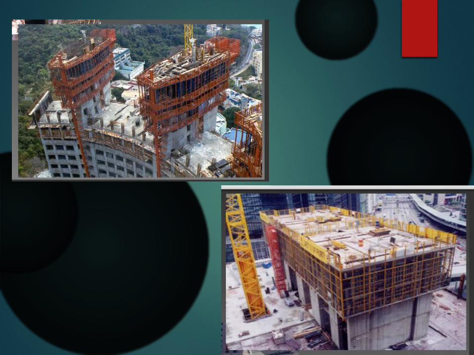
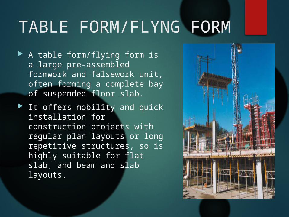
A table form/flying form is a large pre-assembled formwork and falsework unit, often forming a complete bay of suspended floor slab.
It offers mobility and quick installation for construction projects with regular plan layouts or long repetitive structures, so is highly suitable for flat slab, and beam and slab layouts.
TABLE FORM/FLYNG FORM

Table form and flying form is routinely used for:
Residential flats Hotels Hostels Offices Commercial buildings
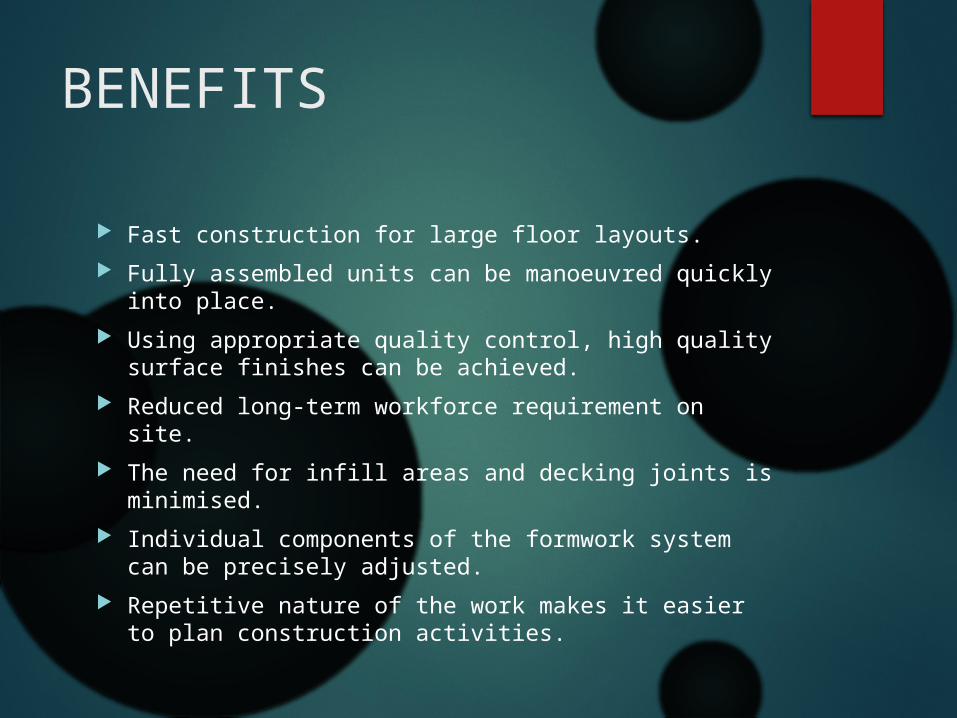
Fast construction for large floor layouts. Fully assembled units can be manoeuvred quickly
into place. Using appropriate quality control, high quality
surface finishes can be achieved. Reduced long-term workforce requirement on site. The need for infill areas and decking joints is
minimised. Individual components of the formwork system can
be precisely adjusted. Repetitive nature of the work makes it easier to
plan construction activities.
BENEFITS

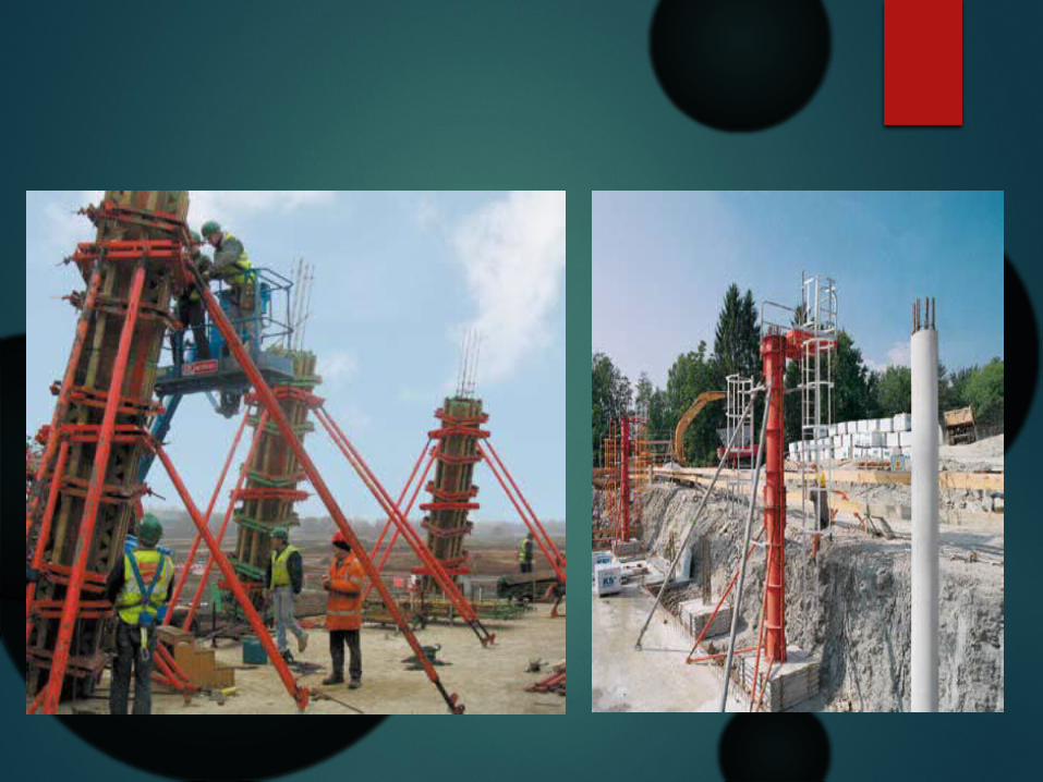
The column formwork systems now available are normally modular in nature and allow quick assembly and erection on-site while minimising labour and crane time.
They are available in steel, aluminium and even cardboard (not reusable but recycled) and have a variety of internal face surfaces depending on the concrete finish required.
Innovations have led to adjustable, reusable column forms which can be clamped on-site to give different column sizes
System column formwork

Tunnel form is used to form repetitive cellular structures, and is widely recognised as a modern innovation that enables the construction of horizontal and vertical elements (walls and floors) together.
Significant productivity benefits have been achieved by using tunnel form to construct cellular buildings such as hotels, low- and high-rise housing, hostels, student accommodation, prison and barracks accommodation.
Tunnel form
Main Equipments
• Tower crane • Concrete pump• Protection screen• Plumb lazer• Platforms, chute and lifts

Climbing Tower Cranes
A climbing tower crane lifts itself up using a climbing attachment with hydraulic jacks that surrounds the mast. The climbing attachment lifts itself up off the erected mast and inserts a new mast section


Climbing Tower Cranes – Tie-in Assembly

Concrete Pump – Self Climbing
The concrete is pumped by a diesel powered, static concrete pump, through a fixed 125 mm pipeline, to the folding placing boom. The boom is mounted on a steel column of up to 20 metres high. The column is supported by a cross base or a system of floor frames set into the concrete floors. With floor frames , the whole column / boom assembly can climb with the building as the work progresses. For placing concrete pumping is faster than using a crane and skip and is less likely to be adversely affected by high winds.

Concrete Pump

Protection Screen - Self climbing
Protection screens enclose the top floors of a high rise enabling construction work to be carry out in great safety, and protected from the weather. The screen will contain any debris and tools that would otherwise fall to the surface.The Protection screen can be moved upwards hydraulically or using a tower crane.

Ensuring Verticality
Leave 3 holes in the floor, forming a right angle. Use a laser plumb bob and a transparent sheet on the floors above. "Jump" the laser every 5 or 6 floors.

Platforms, Chutes & Lift
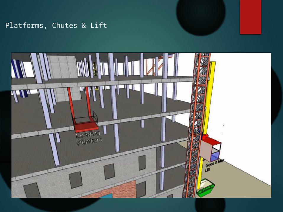
Platforms, Chutes & Lift

THANK YOUFOR YOUR SILENCE