High-Resolution Visualization of Pseudomonas aeruginosa...
12
JOURNAL OF BACTERIOLOGY, Nov. 2005, p. 7619–7630 Vol. 187, No. 22 0021-9193/05/$08.000 doi:10.1128/JB.187.22.7619–7630.2005 Copyright © 2005, American Society for Microbiology. All Rights Reserved. High-Resolution Visualization of Pseudomonas aeruginosa PAO1 Biofilms by Freeze-Substitution Transmission Electron Microscopy Ryan C. Hunter* and Terry J. Beveridge Department of Molecular & Cellular Biology and AFMnet-NCE, College of Biological Science, University of Guelph, Guelph, Ontario N1G 2W1, Canada Received 13 July 2005/Accepted 28 August 2005 High-pressure freeze-substitution and transmission electron microscopy have been used for high-resolution imaging of the natural structure of a gram-negative biofilm. Unlike more conventional embedding techniques, this method confirms many of the observations seen by confocal microscopy but with finer structural detail. It further reveals that there is a structural complexity to biofilms at both the cellular and extracellular matrix levels that has not been seen before. Different domains of healthy and lysed cells exist randomly dispersed within a single biofilm as well as different structural organizations of exopolymers. Particulate matter is suspended within this network of fibers and appears to be an integral part of the exopolymeric substance (EPS). O-side chains extending from the outer membrane are integrated into EPS polymers so as to form a continuum. Together, the results support the concept of physical microenvironments within biofilms and show a complexity that was hitherto unknown. Over the last decade there has been great interest in the study of microbial biofilms because, for many natural prokary- otic communities, this is a preferred natural mode of growth (13). The structural attributes of biofilms have been difficult to study by traditional light microscopic methods (9); these com- munities are thick (and randomly scatter light), are difficult to image via stains (such as the Gram reaction [6]), and are challenging for phase-contrast microscopy. Confocal scanning laser microscopy has been the preferred method of microscopy because many fluorescent probes are now available and be- cause optical sections can be readily rendered into three-di- mensional images with suitable software (43). Indeed, pH dis- continuities have recently been demonstrated in biofilms by confocal scanning laser microscopy using a ratiometric fluores- cent probe, suggesting the existence of so-called microenviron- ments throughout the microbial community (30, 65). Yet the use of any optical microscopy has severe resolution limitations for discerning the structural makeup of individual biofilm cells and their surrounding exopolymeric substance (EPS) matrix. Even such high-resolution instruments as atomic force micro- scopes cannot contribute much to the structural elucidation of biofilms since EPS is too soft and atomic force microscope cantilever force constants are too high for accurate imaging. For high-resolution imaging of such cellular detail in bio- films, we are then forced to use some form of electron micros- copy. Scanning electron microscopes have been used with great benefit on biofilms, especially variable-pressure or environ- mental scanning electron microscopes that can look at speci- mens under high relative humidity (14), but these microscopes can only image the topography of the communities, leaving most of the underlying microbial mass unexamined. By far the best means of analyzing the high-resolution structure of intact biofilm communities is by some form of transmission electron microscopy (TEM) (36). Unfortunately most traditional tech- niques for TEM, such as conventional thin sectioning, are fraught with artifacts since severe preparatory processes first come into play (10). These include harsh chemical fixation using glutaraldehyde and osmium tetroxide, organic solvents (e.g., acetone) for dehydration, and acidic or basic staining agents (e.g., uranyl acetate or lead citrate). This processing initially allowed reasonable general representation of prokary- otic structure and provided the first high-resolution views of biofilms (12, 20). Yet experience has told us that during pro- cessing most proteins are reconfigured, many lipids are ex- tracted, and nucleic acids are atypically condensed (7, 56). Biofilms are among the most difficult biological structures to preserve by conventional means and typically result in poorly preserved cells (especially in the interior of biofilms) and col- lapsed EPS (throughout the biofilm) (10) so that little accurate structural information can be obtained (Fig. 1). Great advances have been made in the vitrification of cells to better preserve high-resolution structure (16). Here, cells are so rapidly frozen that all molecular motion is instantly stopped and the cells are encased in a noncrystalline “glass” of ice (amorphous or nanocrystalline ice) (10). This physical fixation of cells is so extraordinary that if the cells are thawed they come back to life. Standard freeze-plunging, freeze-plunging with controlled humidity, and high-pressure freezing have ad- vanced freezing rates to the point where tens of micrometers of specimen depth can be vitrified. This increased freezing depth is now suitable for preserving the structure of biofilms. One cryotechnique that has assisted in the elucidation of bac- terial structure is the freeze-substitution technique. When freeze- substitution is applied to gram-positive or gram-negative plank- tonic bacteria, much better structural detail is seen (22, 24, 25). In * Corresponding author. Mailing address: Department of Molecular & Cellular Biology and AFMnet-NCE, College of Biological Science, University of Guelph, Guelph, Ontario N1G 2W1, Canada. Phone: (519) 824-4120, ext. 58904. Fax: (519) 837-1802. E-mail: rhunte01 @uoguelph.ca. 7619 on June 8, 2018 by guest http://jb.asm.org/ Downloaded from
Transcript of High-Resolution Visualization of Pseudomonas aeruginosa...
JOURNAL OF BACTERIOLOGY, Nov. 2005, p. 7619–7630 Vol. 187, No. 220021-9193/05/$08.00�0 doi:10.1128/JB.187.22.7619–7630.2005Copyright © 2005, American Society for Microbiology. All Rights Reserved.
High-Resolution Visualization of Pseudomonas aeruginosaPAO1 Biofilms by Freeze-Substitution Transmission
Electron MicroscopyRyan C. Hunter* and Terry J. Beveridge
Department of Molecular & Cellular Biology and AFMnet-NCE, College of Biological Science,University of Guelph, Guelph, Ontario N1G 2W1, Canada
Received 13 July 2005/Accepted 28 August 2005
High-pressure freeze-substitution and transmission electron microscopy have been used for high-resolutionimaging of the natural structure of a gram-negative biofilm. Unlike more conventional embedding techniques,this method confirms many of the observations seen by confocal microscopy but with finer structural detail. Itfurther reveals that there is a structural complexity to biofilms at both the cellular and extracellular matrixlevels that has not been seen before. Different domains of healthy and lysed cells exist randomly dispersedwithin a single biofilm as well as different structural organizations of exopolymers. Particulate matter issuspended within this network of fibers and appears to be an integral part of the exopolymeric substance(EPS). O-side chains extending from the outer membrane are integrated into EPS polymers so as to form acontinuum. Together, the results support the concept of physical microenvironments within biofilms and showa complexity that was hitherto unknown.
Over the last decade there has been great interest in thestudy of microbial biofilms because, for many natural prokary-otic communities, this is a preferred natural mode of growth(13). The structural attributes of biofilms have been difficult tostudy by traditional light microscopic methods (9); these com-munities are thick (and randomly scatter light), are difficult toimage via stains (such as the Gram reaction [6]), and arechallenging for phase-contrast microscopy. Confocal scanninglaser microscopy has been the preferred method of microscopybecause many fluorescent probes are now available and be-cause optical sections can be readily rendered into three-di-mensional images with suitable software (43). Indeed, pH dis-continuities have recently been demonstrated in biofilms byconfocal scanning laser microscopy using a ratiometric fluores-cent probe, suggesting the existence of so-called microenviron-ments throughout the microbial community (30, 65). Yet theuse of any optical microscopy has severe resolution limitationsfor discerning the structural makeup of individual biofilm cellsand their surrounding exopolymeric substance (EPS) matrix.Even such high-resolution instruments as atomic force micro-scopes cannot contribute much to the structural elucidation ofbiofilms since EPS is too soft and atomic force microscopecantilever force constants are too high for accurate imaging.
For high-resolution imaging of such cellular detail in bio-films, we are then forced to use some form of electron micros-copy. Scanning electron microscopes have been used with greatbenefit on biofilms, especially variable-pressure or environ-mental scanning electron microscopes that can look at speci-mens under high relative humidity (14), but these microscopescan only image the topography of the communities, leaving
most of the underlying microbial mass unexamined. By far thebest means of analyzing the high-resolution structure of intactbiofilm communities is by some form of transmission electronmicroscopy (TEM) (36). Unfortunately most traditional tech-niques for TEM, such as conventional thin sectioning, arefraught with artifacts since severe preparatory processes firstcome into play (10). These include harsh chemical fixationusing glutaraldehyde and osmium tetroxide, organic solvents(e.g., acetone) for dehydration, and acidic or basic stainingagents (e.g., uranyl acetate or lead citrate). This processinginitially allowed reasonable general representation of prokary-otic structure and provided the first high-resolution views ofbiofilms (12, 20). Yet experience has told us that during pro-cessing most proteins are reconfigured, many lipids are ex-tracted, and nucleic acids are atypically condensed (7, 56).Biofilms are among the most difficult biological structures topreserve by conventional means and typically result in poorlypreserved cells (especially in the interior of biofilms) and col-lapsed EPS (throughout the biofilm) (10) so that little accuratestructural information can be obtained (Fig. 1).
Great advances have been made in the vitrification of cells tobetter preserve high-resolution structure (16). Here, cells areso rapidly frozen that all molecular motion is instantly stoppedand the cells are encased in a noncrystalline “glass” of ice(amorphous or nanocrystalline ice) (10). This physical fixationof cells is so extraordinary that if the cells are thawed theycome back to life. Standard freeze-plunging, freeze-plungingwith controlled humidity, and high-pressure freezing have ad-vanced freezing rates to the point where tens of micrometers ofspecimen depth can be vitrified. This increased freezing depthis now suitable for preserving the structure of biofilms.
One cryotechnique that has assisted in the elucidation of bac-terial structure is the freeze-substitution technique. When freeze-substitution is applied to gram-positive or gram-negative plank-tonic bacteria, much better structural detail is seen (22, 24, 25). In
* Corresponding author. Mailing address: Department of Molecular &Cellular Biology and AFMnet-NCE, College of Biological Science,University of Guelph, Guelph, Ontario N1G 2W1, Canada. Phone:(519) 824-4120, ext. 58904. Fax: (519) 837-1802. E-mail: [email protected].
7619
on June 8, 2018 by guesthttp://jb.asm
.org/D
ownloaded from

gram-negative bacteria, the periplasm is preserved as a so-calledperiplasmic gel and the chromosomal material of the nucleoid isdispersed throughout the cytoplasm (27, 28). Remarkably, thefreeze-substitution method has even preserved the O-side chainsof the lipopolysaccharide (LPS) on the outer face of the outermembrane of Pseudomonas aeruginosa (41). Even the cell walls ofgram-positive cells show more detail; the walls of Bacillus subtilisrevealed structural aspects of cell wall turnover (24) and myco-bacterial walls showed more accurate distribution of their com-plex polymeric networks (54, 55).
Although there are recognizable problems with the resultspresented by the freeze-substitution technique as being asclose as possible to representing a natural hydrated structure,these are minor and discernible. Some structures, such asmembranes and periplasmic spaces, shrink because of the plas-tic embedment (50, 51). The freeze-substitution technique is,in our opinion, among the best procedures for elucidatingprokaryote structure at the present time and it should providea wealth of new structural data once applied to biofilms.
To this end, freeze-substitution has been used on Haemophi-lus influenzae and the results were promising (67). Unfortu-nately, many of the freeze-substitution images of this articleshowed poorly frozen cells with little detail. In addition, Hae-mophilus has rarely been used as a common model biofilmmicroorganism and Haemophilus biofilms are therefore diffi-cult to compare with more frequently used models. In thispaper we show our results using the freeze-substitution methodon a biofilm of the frequently used model bacterium Pseudo-monas aeruginosa PAO1.
MATERIALS AND METHODS
Bacterial strains, culture conditions, and biofilm growth. P. aeruginosa PAO1was used throughout this study and was obtained from J. S. Lam (University ofGuelph) and was maintained on Trypticase soy agar (TSA, Becton Dickinson).Planktonic cultures were grown in a dilute Trypticase soy broth medium (dTSB)at a concentration of 3 g per liter (1/10th the recommended concentration) atroom temperature to late-exponential phase (optical density at 600 nm � 0.6).Cells were washed twice in 50 mM HEPES buffer and were then processed usingfreeze-substitution.
Biofilms were cultivated in dTSB on sapphire disks (Al2O3) that were 50 �mthick and 1.4 mm in diameter (Leica Microsystems). Sapphire disks were placedin the lumen of silicone tubing (inner diameter � 1.57 mm) and the entire system(medium, tubing, sapphire disks, waste reservoir) was autoclaved prior to inoc-ulation. Once sterile, the tubing was connected to a Manostat Carter multichan-nel peristaltic pump (Barnant, Barrington, IL) and was preconditioned withmedium for 1 h prior to inoculation. At this point, the flow system was inoculatedwith an overnight culture of PAO1 (optical density at 600 nm � 0.6) through anupstream injection port. After inoculation, flow was arrested to facilitate bacte-rial adhesion for 1 h. Following attachment of cells to the sapphire disks, flow wasresumed and the dTSB was pumped through at a constant rate of 0.1 ml/min for7 days.
After 7 days of growth, flow was stopped and sterile forceps were used toremove the sapphire disks. They were then placed on Whatman no. 1 filter paperto remove excess culture medium from the underside of the disk, while leavinga thin layer of medium on top of the cells to keep them fully hydrated throughoutfreezing. sapphire disks were then placed into flat specimen holders (Leica) thatwere 1.5 mm in diameter. Immediately prior to freezing, a 10% sucrose solutionwas placed over top of the biofilm to serve as a cryoprotectant (51).
High-pressure freezing and freeze-substitution. (i) Biofilms. The sapphiredisks were frozen using a Leica EM PACT high-pressure freezer. Once sampleswere frozen they were maintained under liquid nitrogen (�135°C), and trans-ferred into 2-ml cryovials (Nalgene) containing 2% (wt/vol) osmium tetroxide(OsO4) and 2% (wt/vol) uranyl acetate in anhydrous acetone (substitution me-dium). When indicated, other chemical fixatives were tried in the substitution
FIG. 1. P. aeruginosa PAO1 biofilm prepared by conventional TEM processing. These micrographs clearly show the heterogenous distributionof biomaterials such as membrane vesicles (white arrows), cellular detritus (star), and other extracellular polymers. Unfortunately, little infor-mation about biofilm structure can be acquired from such micrographs since conventional processing induces features such as membrane artifacts(white arrowheads) and condensed cytoplasmic material (black arrowheads). Additionally, conventional methods fail to reveal the true nature ofextracellular polymers that are known exist between cells. Bar � 2 �m.
7620 HUNTER AND BEVERIDGE J. BACTERIOL.
on June 8, 2018 by guesthttp://jb.asm
.org/D
ownloaded from

medium, such as 0.075% (wt/vol) ruthenium red and 1% (wt/vol) Alcian blue.The vials were placed into a Leica EMAFS unit for substitution. Here, thebiofilms were substituted under strictly controlled conditions as outlined below.
(ii) Planktonic cells. Planktonic cells were resuspended in a 10% (wt/vol)sucrose solution and were immediately injected via syringe into thin copperspecimen tubes (Leica, inner diameter � 350 �m) for freezing. Tubes werehigh-pressure frozen identically to biofilm samples, but they required trimminginto two halves to expose frozen cells to the substitution medium. Tubing halveswere then placed in cryovials and were substituted in the EMAFS unit.
(iii) Freeze-substitution. Samples were freeze-substituted under controlledtemperatures according to the program outlined in Table 1 for a total 72 h. Thesesubstitution steps involved alternating between maintaining samples at a con-stant subzero temperature and periods of gradual warming. Low temperaturesprevented large ice crystal formation, whereas the warmer periods encouragedchemical substitution. Once samples reached room temperature, disks/tubeswere removed from the EMAFS and were washed carefully in 100% acetone for10 min. Disks were then covered with a thin layer of Epon resin and wereincubated at 60°C overnight. Once polymerized, the resin was removed from thecopper holder and the sapphire disks remained embedded in the resin. Theblocks were then placed in flat embedding molds and re-embedded in Epon resinat 60°C for 48 h to produce a block shape conducive to thin sectioning. Copperspecimen tubes were washed carefully in acetone for 10 min, and were embeddedin Epon at 60°C for 48 h.
Conventional embeddings for comparison purposes. Biofilms grown on sap-phire disks were enrobed in 2% (wt/vol) Noble agar and placed in 2.5% (vol/vol)glutaraldehyde for 2 h. Blocks were washed twice in HEPES buffer and fixed in2% (wt/vol) OsO4 for 2 h, followed by 2% (wt/vol) uranyl acetate staining for 2 h.Blocks were washed twice in HEPES buffer and were dehydrated through agraded ethanol series (25%, 50%, 75%, 95%, and three times at 100%) for15 min in each solution. Blocks were suspended in a 50:50 ethanol/LR Whiteresin solution for 30 min, followed by 100% LR White for 1 h. Blocks wereembedded in gelatin capsules filled with fresh LR White resin, which were thenpolymerized at 60°C for 1 h.
Transmission electron microscopy. Biofilms prepared by conventional embed-ding and freeze-substitution were thin sectioned on a Reichert-Jung Ultracut Eultramicrotome. Before thin sectioning, the sapphire disks were peeled awayfrom the Epon, but the biological material remained embedded in the plasticresin and could be sectioned. For planktonic samples, the copper tubes requiredsome trimming so that no copper came into contact with the knife face duringsectioning. Sections were mounted on Formvar- and carbon-coated 200-meshcopper grids. To improve contrast, sections were post stained in 2% (wt/vol)uranyl acetate. Electron microscopy was performed on a Philips CM10 trans-mission electron microscope operating at 80 kV under standard operating con-ditions. All observations reported in this paper are based on interpretations from5 to 10 thin sections from numerous biofilm samples.
SDS-PAGE and Western immunoblotting. LPS was prepared from planktonicand biofilm cells as described by Hitchcock and Brown (26). These extracts wereseparated by sodium dodecyl sulfate (SDS)-polyacrylamide gel electrophoresis(PAGE) (standardized to 25 �g of protein per lane) and the bands were thentransferred to nitrocellulose sheets for Western immunoblotting, as describedpreviously (1). I.e., bands were transferred at 100 V for 60 min, washed briefly inTris-buffered saline (TBS), and placed in blocking buffer (3% skim milk in TBS)for 60 min. Sheets were then rinsed again in TBS and reacted with either N1F10(anti-A-band LPS) (40) or MF15-4 (anti-B-band LPS) (39) at room temperature
for 2 h and at 4°C overnight. Bound antibodies were washed twice in TBS andlabeled with 0.05% (vol/vol) horseradish peroxidase-conjugated goat anti-mouseimmunoglobulin antibody in TBS for 2 h at room temperature. The bands werethen developed for 20 min in 0.1 M bicarbonate buffer (pH 9.8) containing0.33 mg ml�1 Nitro Blue Tetrazolium (Sigma), and 0.15 g ml�1 5-bromo-4-chloroindolylphosphate (Sigma). Development was stopped by rinsing in deion-ized water.
RESULTS AND DISCUSSION
TEM has allowed significant advances in the understandingof biofilm physiology. These include an increased understand-ing of infection mechanisms (35), antibiotic tolerance (66, 72),wastewater processes (17), river water communities (45), andbiofilm geochemistry (34, 47). In biological samples, however,TEM procedures can result in the distortion of structural in-formation, either through molecular extraction or redistribu-tion, dehydration and/or aggregation of the extracellular poly-mers, and through thin sectioning. More often than not, theloss of such information cannot be regenerated afterwards,which results in limited information that is difficult to assess.To this end, biofilms present a major challenge to the micros-copist, as they are exemplary specimens prone to artifact andinaccurate imaging.
Biofilms are highly organized aggregates of microorganismstypically surrounded by densely packed matrices of extracellu-lar polymeric substances (EPS). Commonly, EPS provides�85% vol/vol of the space occupied by a biofilm (but thisfigure widely varies) and the remainder (�15%) consists ofbacteria. EPS is not simply made up of so-called exopolysac-charides (since it is much more complex) and includes heter-ogeneous combinations of polysaccharides, proteins, andminor amounts of lipids, nucleic acids, and other polymers(11, 64, 68). In fact, larger tangible biomaterials such as outermembrane vesicles, flagella, phages, pili, and debris fromlysed cells are also present in variable amounts (Fig. 1) (S. R.Schooling, R. C. Hunter, and T. J. Beveridge, unpublished).Though this heterogeneous mixture of compounds and free-existing structures constitutes such a significant proportion ofthe biofilm matrix, these constituents of bacterial communitiesremain to be accurately visualized and characterized via TEM.
EPSs are known to be highly hydrated (�97% of EPS massexists as water) and are thought to alternate physically betweengel and liquid states (4). Because of this highly hydrated na-ture, the extracellular polymers are difficult to observe (littleinnate electron scattering power) and to preserve (too muchwater). In conventional preparation regimens, aldehydes (e.g.,glutaraldehyde), uranyl contrasting agents, and osmium com-plexes are unable to adequately cross-link the polymeric com-ponents (e.g., polysaccharide-based components such as algi-nate in mucoid P. aeruginosa strains) and bioparticulates into aresilient network mimicking the natural matrix material. As aresult, when dehydration is performed (to prepare the samplefor plastic embedding), hydration shells surrounding both thepolymers and particulates collapse. Polymer fibers (both poly-saccharides and nucleic acids) artificially condense, lipids re-organize or are extracted, and proteins are reconfigured. It hasbeen assumed, but never adequately shown using TEM, thatthese fibrous polymers and particulates form an extensive poly-mer meshwork throughout the biofilm. Unfortunately, in aconventional embedding we see a distribution of cells with
TABLE 1. EMAFS freeze-substitution regimen
Step Time(h)
Temp(°C)
Slope(°C h�1)
T1a 20 �90S1 3 10T2 10 �60S2 3 10T3b 20 �30S3 5 10T4 11 20
a Samples frozen at �180°C in the EMPACT were transferred to substitutionmedium under liquid nitrogen and then placed in the EMAFS, which wasprecooled to �90°C.
b The EMAFS unit required two programming steps. One program endedwhile another started during T3.
VOL. 187, 2005 FREEZE-SUBSTITUTION OF BIOFILMS 7621
on June 8, 2018 by guesthttp://jb.asm
.org/D
ownloaded from

little substance between them (Fig. 1). The cells themselves arepoorly represented since their membranes are no longer tautand their DNA has condensed into a central cytoplasmic ag-gregate.
EPS remains an elusive structure even though it is an im-portant component of biofilms to visualize. This substancecertainly plays a role in the chemical (pH, redox and geochem-istry of microenvironments) and physical properties (rheology,viscosity, elasticity, penetration barrier, etc.) of biofilms, and incell physiology (toxicity tolerance, cell-cell signaling, nutrientassimilation, attachment/detachment, etc.). Indeed, the entireconcept of there existing so-called microenvironments distrib-uted throughout biofilms relies on there being discontinuitiesbetween groups of cells within the overlying matrix. Intuitively,these discontinuities should have subtly different make ups thatcould be visualized by TEM if they are well enough preserved.Artifacts expressed by conventional embedding have beenknown for decades (22, 23). Attempts have been made tostabilize, visualize, and identify extracellular polymers throughthe use of electrostatic cross-linking agents (e.g., multivalentcations), cationized ferritin, and gold-conjugated lectins(3, 29, 31, 32, 33, 38). Though worthwhile, these studies failto illustrate the true nature of biofilm cells and the EPS thatsurrounds them.
All aspects of cryo-TEM ultimately rely on the initial freez-ing step, since cells have to be frozen so rapidly that that theyare vitrified in amorphous ice. Standard freezing methods,such as plunging samples into a slush of propane held at�196°C (23), can only reliably vitrify �1 to 10 �m of sampledepth, which is unsuitable for biofilm studies. Better vitrifica-tion occurs at high pressure under low temperatures, therebyensuring good freezing to depths approaching hundreds ofmicrometers, and we used high-pressure freezing in thispresent study (Fig. 2 shows a diagram of the apparatus andexplains the process). At high pressure the freezing tempera-ture of water is lowered and the likelihood of undesired ice
crystal nucleation decreases, which is especially important forsmall particles such as bacteria and their EPS particulates (51).
Figure 3 shows one of our typical freezing data diagrams andindicates that this biofilm sample was cooled at a rate of 1.1 �104°C per s under a pressure of �2 � 105 kPa. Such conditionspreclude the formation of crystalline ice throughout thick bio-film specimens. Additionally, the thermal conductivity of thesapphire substrata ensures that uniform cooling rates areachieved throughout the samples.
Once frozen, freeze-substitution samples have to bechemically stabilized while cellular water is replaced by anorganic solvent before the specimens are warmed to room
FIG. 2. A) Schematic of the flat specimen holder for freeze-substitution. In short, a biofilm grown on a sapphire disk was briefly dried andtransferred to a copper flat specimen carrier. The holder was then filled with a 10% sucrose solution, which served as a cryoprotectant throughoutthe freezing process. B) The 1.5-mm-diameter specimen carrier (i) was then tightly secured into a loading pod (ii). This entire apparatus wasinserted into the high-pressure freezer using a loading rod (iii). Samples were immediately frozen under high pressure, which was applied to theunderside of the biofilm substratum as shown in A. An extensive technical description of the high-pressure freezer and the freezing process canbe found in Studer et al. (63).
FIG. 3. Typical temperature and pressure changes of the biofilmspecimen throughout high-pressure freezing as established by theEMPACT system (Leica Microsystems). This diagram reveals a pres-sure of over 2 � 105 kPa (heavy line) was applied, followed by atemperature decrease from 20°C to below �190°C (thin line) at acooling rate of 1.1 � 104°C per s. These conditions permit excellentvitrification in specimens up to �200 �m thick.
7622 HUNTER AND BEVERIDGE J. BACTERIOL.
on June 8, 2018 by guesthttp://jb.asm
.org/D
ownloaded from

FIG. 4. TEM micrograph of a full biofilm profile in thin section (A), which reveals extensive heterogeneity in terms of cell distribution andphysiological status. Prior to sectioning, the substratum was situated at the bottom of the micrograph, while the top represents the biofilm-mediainterface. Each biofilm shows diffuse (black arrow) and tightly packed cells (arrowhead) of with interstitial regions of “void” space (star). A fewlysed cells are also visible (white arrow). These characteristics are represented at higher magnification in B, C, and D. B) Cells towards thebiofilm-medium interface were few and spread far apart relative to the rest of the biofilm. C) Cells situated away from the biofilm-medium interfacewere generally tightly clustered and packed along the same axis. D) Some areas adjacent to healthy cells were characterized by extensive cell lysis.These regions appeared to be randomly distributed, but were not found in all biofilms. Bars: A � 5 �m; B, C, and D � 1 �m.
7623
on June 8, 2018 by guesthttp://jb.asm
.org/D
ownloaded from

temperature so that they can be embedded in plastic for thinsectioning. Over this time, at low temperature (ca. �80°C),biological polymers are cross-linked and stabilized by osmicacid and uranyl ions while in their native (frozen) confor-mations. Although the action of these chemical agents un-der low temperature is poorly understood, they are believedto be nonreactive below �90°C (21). However, at such a lowtemperature, molecules are physically fixed in place, andreactive groups become available for chemical fixatives fol-lowing a slight rise in temperature. It is also believed, how-ever, that cellular water can recrystallize at slightly warmertemperatures (ca. �80°C), so careful control of substitutiontemperatures and their duration is vital to successful pres-ervation of biological specimens (P. Hyam, Leica Microsys-tems, personal communication). Through trial and error, wehave worked out a regimen that successfully minimizes cellshrinkage, collapse of delicate polymers, and reorganizationof molecular components in P. aeruginosa PAO1 biofilms(Table 1).
Figure 4A reveals a full biofilm profile in thin section fromthe substratum to the bulk fluid interface and represents a full60 �m of biofilm depth. Higher magnifications of selectedregions of the biofilm (from top to bottom) give a better ideaof what the cells look like throughout the biofilm community(Fig. 4B to D). These micrographs reveal extensive heteroge-neity in terms of cell distribution, a frequently observed char-acteristic of biofilms through confocal microscopy. Cells towardsthe biofilm surface were few and spread far apart (Fig. 4A and B),though some pockets of higher cell density were observed aswell. Cells in deeper areas of the biofilm were generally ob-served to be clustered closer together and frequently alignedwith one another along the same cell axis (those in Fig. 4C areall cross-sectioned because of this).
Because the cells are enrobed in EPS, mobility is reducedrelative to planktonic cultures, and division axes would have acommon alignment so that packets of progeny would remainaligned as they grew and divided. This alignment could bebeneficial since it provides closer packing of cells and (possi-bly) easier intercellular communication. Close to these packetsof aligned healthy cells, regions of severe cell lysis were alsoobserved (Fig. 4D). This was despite the nutrient-rich growthconditions that the biofilm was under throughout its growth.One would expect that these regions of lysis would becomemore frequent as the more interior regions of the biofilm wereobserved, but this was not the case. These lysis regions seemedrandomly positioned and were always close to more healthyregions (Fig. 4A). This appears to corroborate suggestions thatbiofilm microbes are able to survive at the expense of thosearound them (i.e., an altruistic growth strategy) (37). It shouldbe noted, however, that significant cell lysis was not observed inall micrographs (see Fig. 4A).
Clearly, the areas of the biofilm that are filled with cells andmatrix are complex in that packets of cells in many differentphysiological states are found. Yet, regions of extremely lowcell density are also seen in Fig. 4A. We believe these to bevoids or water channels, and this would confirm the complexbiofilm macrostructure seen by confocal microscopy (44). Thesampling area of a thin section is very limited and large mac-rostructures such as water channels are difficult to interpret but(our) confocal measurements of the biofilms using green flu-orescent protein-labeled cells suggested that the biofilmsranged from 60 to 80 �m in thickness. Since this confocalthickness is consistent with that seen with our freeze-substitu-tions, the biofilm macrostructure seems to be well preservedand these low-cell-density voids must be water channels. Inter-estingly, measurements of conventionally embedded biofilms
FIG. 5. A) TEM micrograph of freeze-substituted PAO1 biofilm cells. In this image and at higher resolution (B), it is evident that conventionalembedding artifacts are not present in these cells, as they are characterized by an evenly stained plasma membrane (PM), a semitranslucentperiplasmic gel (PG), a taut outer membrane (OM), and evenly distributed cytoplasm with ribosomes spread throughout. The fibrous backgroundmaterial (EPS) emanating from the lipopolysaccharides (LPS) on the outer membrane is absent from planktonic cells (C), which suggests that thesefeatures are the extracellular biofilm matrix. Bar � 0.5 �m.
7624 HUNTER AND BEVERIDGE J. BACTERIOL.
on June 8, 2018 by guesthttp://jb.asm
.org/D
ownloaded from
revealed that they had shrunk by �25% (data not shown). Thissubstantial size difference suggests that quantifying biofilmmorphology using cryotechniques is more representative oftheir natural state.
As previously discussed, conventional embeddings arefraught with artifacts (see Fig. 1) which are not seen in thefreeze-substitution samples. High magnification aptly demon-strates this (Fig. 5). Here, the majority of cells have a well-preserved cell envelope that consists of a smooth, evenlystained plasma membrane, a semitranslucent periplasmic gel,and an asymmetrically stained, taut outer membrane (seeFig. 5B for a high-resolution micrograph of the cell envelope).The asymmetry seen in the outer membrane is a reflection ofthe lipid asymmetry of this bilayer; most LPS resides on theouter face of the membrane whereas most phospholipid is onthe inner face. LPS stains darker than phospholipid because ofits higher charge density (5). Remarkably, the appearance ofthe cell envelope approaches profiles observed in frozen hy-drated sections viewed by cryo-TEM (51). Here, image con-trast is based on mass distribution (i.e., the higher proportionof phosphorus in LPS as opposed to that in phospholipid) ofthe biomaterial and not on the staining reagents, as in freeze-substitution (56). This confirms how well our freeze-substi-tuted cells have been preserved within the biofilm.
In Fig. 5A the cells look remarkably robust since their cyto-plasms are filled with ribosomes and their chromosome isspread throughout the entire cytoplasm; these are structuraltraits suggesting active metabolic processes and protein syn-thesis (21, 25, 27, 28, 50, 51). This evenly distributed cytoplasmis in contrast to that seen in the study by Webster et al. (67).These features were surprising since we often naturally assumethat many biofilm cells would be under nutrient limitation (nomatter the flow rate) and, accordingly, the cells should not lookso healthy. Yet studies do suggest strong metabolic activity(57), and recent DNA microarray studies reveal ribosomalgene expression to be upregulated in P. aeruginosa, Escherichiacoli, and B. subtilis biofilms versus their planktonic counter-parts (60, 62, 69).
It has been suggested that such lines of evidence may be indic-ative of cells achieving a faster growth rate than expected byenjoying a greater availability of nutrients either through catabo-lism of the surrounding matrix, or through catabolism of deadcells (46). It is also important to consider that our growth medium(1/10th the recommended concentration of TSB), though dilute,is still extremely rich relative to many natural biofilm environ-ments. Our results indicate that biofilms consist of either pocketsof highly active cells (Fig. 5A) or pockets of cell lysis (Fig. 4D)with few cells at intermediate metabolic rates. We did not findthat our cells suffered from freezing damage near the base of thebiofilm as was previously shown (67).
As comparison for our biofilm study, we also freeze-substi-tuted planktonic cells of PAO1. These were also well preservedand possessed most of the cellular attributes seen in the biofilmbacteria (cf. Fig. 5A and C). The most apparent difference wasseen with the contrast of the background of both samples; thebiofilm cells had a darker pebbly background whereas theplanktonic cells had little background at all. Careful observa-tion of the biofilm cells revealed that most background mate-rial was closest to the cell surfaces and that the outer mem-brane surface possessed fibers emanating from it (Fig. 5A and
B). Since these structural features were only seen in the biofilmsamples, it was apparent that they were associated with theextracellular matrix and that this was the EPS.
Figure 6 reveals this in more detail. Here a close-up of thematrix is taken from a midpoint between two cells (Fig. 6A) toshow the granularity of the EPS (Fig. 6B). Obviously, much ofthis granularity could be due to the staining complexes associ-ated with the EPS, but one certainly gets the impression of highdensity versus low density polymeric regions (Fig. 6B). In con-ventional embeddings, various attempts have been made tostabilize acidic extracellular polymers through electrostaticcross-linking using fixatives such as ruthenium red (48) andAlcian blue (61), which are both electron dense and add con-trast to the specimen. These attempts have been somewhatsuccessful with other organisms (33, 71), but by their verynature (being multivalent cations) they can artificially con-dense polymeric materials. No previous successful observa-tions have been reported for P. aeruginosa. Here, throughfreeze-substitution, we reveal fine detail within the EPS poly-mers without the aid of these extraneous cross-linking agents.
Furthermore, in our study, the EPS surrounding cells adja-cent to the substratum was found to be much more heteroge-nous than that in other regions of the biofilm. Figures 6C to Freveal at least three distinct configurations of EPS polymerarrangement, if not distinct polymeric types. In Fig. 6C, thereis one lysed cell, some membranes (presumably from anotherlysed cell), and some membrane vesicles, which together em-phasize the particulate nature of some EPS components. Thisis a common trait seen in all regions of the extracellular matrixand emphasizes the extreme complexity of the EPS. Some ofthese features are shown at higher magnification in Fig. 6D toF. The complexity shown in these micrographs could clearly, atleast in part, be responsible for the physical and chemicaldiscontinuities seen throughout a single biofilm, which mani-fest themselves as microenvironments (30).
Unfortunately, the exact chemical nature of PAO1’s EPSstill remains to be fully characterized. A recent study describ-ing the EPS of PAO1 biofilms identified the major carbohy-drate moieties in this to include glucose, rhamnose, mannose,xylose, 3-deoxy-D-manno-oct-2-ulosonic acid (KDO),N-acetyl-galactosamine, N-acetylfucosamine, and N-acetylglucosamine(70). More recently, two genetic loci (psl and pel) responsiblefor the production of mannose-rich (psl) and glucose-rich (pel)polymer components of P. aeruginosa EPS (18, 19, 52) wereidentified. With the exception of KDO with its ionizable car-boxylate, most of the sugars described in these studies areneutrally charged or sugars with a possible ionizable aminegroup (depending on polymeric linkage), which may be difficultto stain. Accordingly, most staining of this PAO1 polymericEPS must be due to the KDO moiety. It also must be remem-bered, though, that other highly acidic polymers may also bepresent, such as DNA (11, 52, 68).
The O-side chain of LPS is another polymeric unit that mustbe considered in our study, since LPS has been implicated inthe architecture of P. aeruginosa biofilms (58). Its presenceaffects the attachment of bacteria to a surface (49) and some ofthe chemical constituents identified in PAO1’s EPS are similarto those in the O-side chain as well as in the core oligosaccha-ride (70). P. aeruginosa PAO1 (serotype 05) produces twotypes of O-side chains, termed A-band and B-band. The
VOL. 187, 2005 FREEZE-SUBSTITUTION OF BIOFILMS 7625
on June 8, 2018 by guesthttp://jb.asm
.org/D
ownloaded from

7626 HUNTER AND BEVERIDGE J. BACTERIOL.
on June 8, 2018 by guesthttp://jb.asm
.org/D
ownloaded from

A-band has a relatively simple, uncharged O-side chain con-sisting of �10 to 20 repeating units of a D-rhamnose trimer (2).This neutrally charged polymer is difficult to stain and visualizeusing TEM (41). The B-band O-side chain is serotype specificand is much more complex.
The B-band O-antigen of the PAO1 strain used in thisstudy (serotype 05) consists of highly charged repeatingtrisaccharide consisting of two units of �-D-mannuronic acidand one N-acetyl-D-fucosamine (35). This polymer is moreeasily visualized, since the uronic acid residues are able tobind uranyl ions from the substitution medium. If present onbiofilm cells, we expected to see the B-band O-side chains asfibrous polymers extending from the outer membrane. In-deed, Fig. 5A and 7A reveal such fibrous polymers on thebiofilm bacteria, which suggested the presence of B-bandO-antigen. This was confirmed using SDS-PAGE and West-ern immunoblotting using monoclonal antibodies specificfor these two O-antigens (Fig. 7B and C). Both A- andB-bands were present. We were surprised to see these fea-tures since Beveridge et al. (8) reported that the A�B�
phenotype of PAO1 cells within mature biofilms was dis-placed by A�B� over a 144-h growth period when grown ina chemically defined growth medium.
In our present study, we used a more enriched medium(dTSB), which could explain the difference. Our micrographs(cf. Fig. 5A and 5C) and Western blots did, however, indicatethat B� band LPS was produced in lower amounts than inplanktonic cultures, which is similar to results published byLangley and Beveridge (42). Since LPS was not as visible onsome cell surfaces in the biofilm (cf. Fig. 7A and D), it ispossible that B-band expression is repressed under certainmicroenvironment conditions, which again reveals the complexheterogeneity within a single biofilm. This is consistent withplanktonic studies that have shown P. aeruginosa to expressthese two types of LPS differently under environments of ox-ygen stress, low pH, high temperature, and various nutrientregimens (53, 59). These results provide further evidence forlocalized microenvironments throughout P. aeruginosa biofilmsand may also complement other clinical studies which haveshown cystic fibrosis isolates to be A�B� (40).
FIG. 6. A) TEM micrograph of a cluster of biofilm cells surrounded by an extensive EPS network. Most EPS is present near the cell surfaces. B)High-resolution image of the EPS region marked in A (see text for details). Microenvironments of EPS of high (HD), intermediate (ID), and low (LD)density are clearly present. C) Some areas adjacent to the substratum reveal more extensive heterogeneity. At least three polymer types or arrangementsare present in this small area of the biofilm (outlined) and are shown at higher magnification in panels D, E, and F. While the exact chemical natureof these polymeric configurations is unknown, these micrographs reveal the extensive complexity of the EPS matrix. Bars � 1 �m.
FIG. 7. A) High-resolution image of a biofilm PAO1 cell envelope. LPS can be seen extending from the outer membrane as a fibrous polymerbrush (arrows), though it appears to be less electron dense than the surface of planktonic cells (see Fig. 5C). The electron density is likely providedby uranyl ions, which suggests that this polymer is B-band LPS. Bar � 100 nm. B and C) Western immunoblots of LPS isolated from planktonic(lane 1) and biofilm (lane 2) PAO1 cells. SDS-PAGE gels were standardized to 25 �g protein per lane and reacted with either (B) anti-A bandor (C) anti-B band monoclonal antibodies. These blots confirm the presence of B-band LPS in PAO1 biofilms, though it is evident that, relativeto planktonic PAO1 cells, B-band is produced in smaller amounts. D) LPS was not visible on several clusters of biofilm cells, which is suggestiveof localized microenvironments in which PAO1 alters the characteristics of its cell envelope. Bar � 100 nm.
VOL. 187, 2005 FREEZE-SUBSTITUTION OF BIOFILMS 7627
on June 8, 2018 by guesthttp://jb.asm
.org/D
ownloaded from
It was interesting to see that freeze-substitution offered anindistinct line as to where the O-side chains and the EPS met(Fig. 5, 6, and 7). EPS blended into the side chains so com-pletely that it was impossible to ascertain where the side chainsended and where the EPS polymers began. Since chemicalanalyses suggest that the side chains and the EPS polymershave a common chemical pedigree, it is possible that some ofthese EPS polymeric fibers are O-side chains that have beenexcised from LPS molecules. At the same time, when cells wereseen in close proximity to each other (Fig. 5, 6, and 7), theirO-side chains appeared to intermingle, suggesting a closerunion than normally seen with planktonic cells. This could aidintercellular communication between biofilm bacteria.
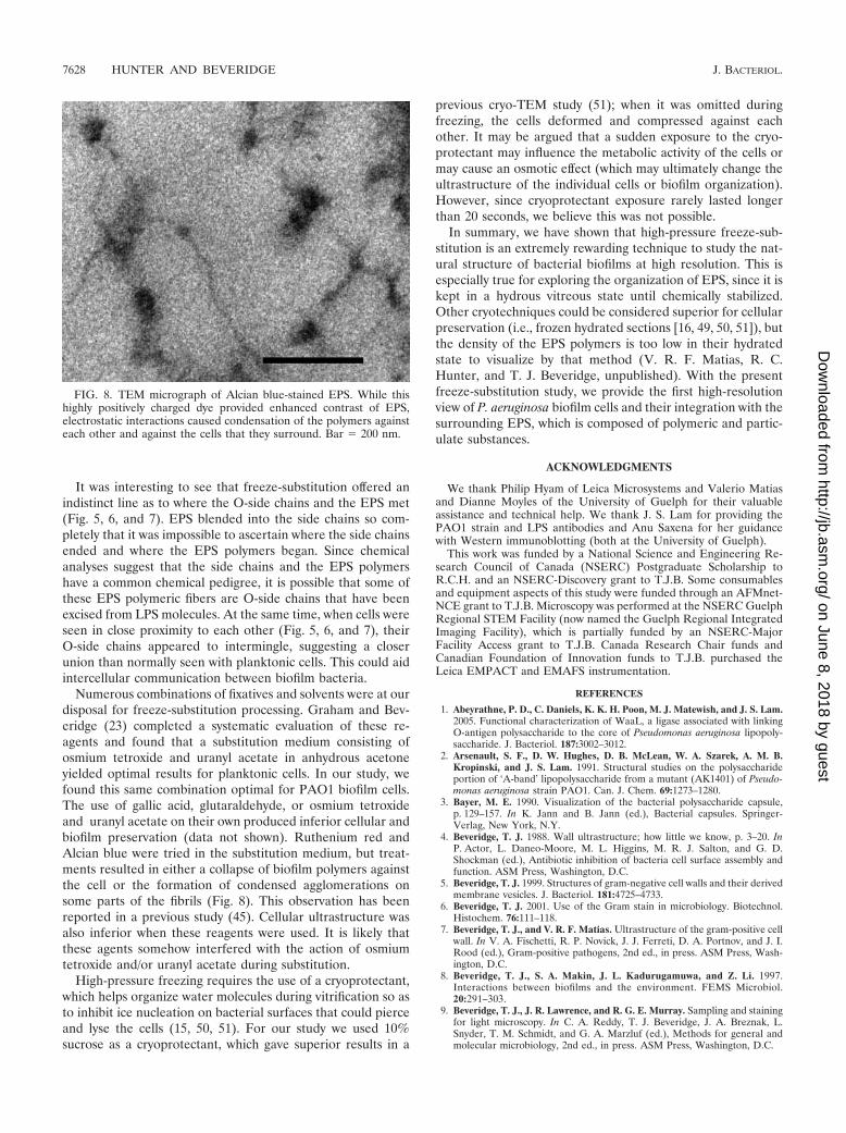
Numerous combinations of fixatives and solvents were at ourdisposal for freeze-substitution processing. Graham and Bev-eridge (23) completed a systematic evaluation of these re-agents and found that a substitution medium consisting ofosmium tetroxide and uranyl acetate in anhydrous acetoneyielded optimal results for planktonic cells. In our study, wefound this same combination optimal for PAO1 biofilm cells.The use of gallic acid, glutaraldehyde, or osmium tetroxideand uranyl acetate on their own produced inferior cellular andbiofilm preservation (data not shown). Ruthenium red andAlcian blue were tried in the substitution medium, but treat-ments resulted in either a collapse of biofilm polymers againstthe cell or the formation of condensed agglomerations onsome parts of the fibrils (Fig. 8). This observation has beenreported in a previous study (45). Cellular ultrastructure wasalso inferior when these reagents were used. It is likely thatthese agents somehow interfered with the action of osmiumtetroxide and/or uranyl acetate during substitution.
High-pressure freezing requires the use of a cryoprotectant,which helps organize water molecules during vitrification so asto inhibit ice nucleation on bacterial surfaces that could pierceand lyse the cells (15, 50, 51). For our study we used 10%sucrose as a cryoprotectant, which gave superior results in a
previous cryo-TEM study (51); when it was omitted duringfreezing, the cells deformed and compressed against eachother. It may be argued that a sudden exposure to the cryo-protectant may influence the metabolic activity of the cells ormay cause an osmotic effect (which may ultimately change theultrastructure of the individual cells or biofilm organization).However, since cryoprotectant exposure rarely lasted longerthan 20 seconds, we believe this was not possible.
In summary, we have shown that high-pressure freeze-sub-stitution is an extremely rewarding technique to study the nat-ural structure of bacterial biofilms at high resolution. This isespecially true for exploring the organization of EPS, since it iskept in a hydrous vitreous state until chemically stabilized.Other cryotechniques could be considered superior for cellularpreservation (i.e., frozen hydrated sections [16, 49, 50, 51]), butthe density of the EPS polymers is too low in their hydratedstate to visualize by that method (V. R. F. Matias, R. C.Hunter, and T. J. Beveridge, unpublished). With the presentfreeze-substitution study, we provide the first high-resolutionview of P. aeruginosa biofilm cells and their integration with thesurrounding EPS, which is composed of polymeric and partic-ulate substances.
ACKNOWLEDGMENTS
We thank Philip Hyam of Leica Microsystems and Valerio Matiasand Dianne Moyles of the University of Guelph for their valuableassistance and technical help. We thank J. S. Lam for providing thePAO1 strain and LPS antibodies and Anu Saxena for her guidancewith Western immunoblotting (both at the University of Guelph).
This work was funded by a National Science and Engineering Re-search Council of Canada (NSERC) Postgraduate Scholarship toR.C.H. and an NSERC-Discovery grant to T.J.B. Some consumablesand equipment aspects of this study were funded through an AFMnet-NCE grant to T.J.B. Microscopy was performed at the NSERC GuelphRegional STEM Facility (now named the Guelph Regional IntegratedImaging Facility), which is partially funded by an NSERC-MajorFacility Access grant to T.J.B. Canada Research Chair funds andCanadian Foundation of Innovation funds to T.J.B. purchased theLeica EMPACT and EMAFS instrumentation.
REFERENCES
1. Abeyrathne, P. D., C. Daniels, K. K. H. Poon, M. J. Matewish, and J. S. Lam.2005. Functional characterization of WaaL, a ligase associated with linkingO-antigen polysaccharide to the core of Pseudomonas aeruginosa lipopoly-saccharide. J. Bacteriol. 187:3002–3012.
2. Arsenault, S. F., D. W. Hughes, D. B. McLean, W. A. Szarek, A. M. B.Kropinski, and J. S. Lam. 1991. Structural studies on the polysaccharideportion of ‘A-band’ lipopolysaccharide from a mutant (AK1401) of Pseudo-monas aeruginosa strain PAO1. Can. J. Chem. 69:1273–1280.
3. Bayer, M. E. 1990. Visualization of the bacterial polysaccharide capsule,p. 129–157. In K. Jann and B. Jann (ed.), Bacterial capsules. Springer-Verlag, New York, N.Y.
4. Beveridge, T. J. 1988. Wall ultrastructure; how little we know, p. 3–20. InP. Actor, L. Daneo-Moore, M. L. Higgins, M. R. J. Salton, and G. D.Shockman (ed.), Antibiotic inhibition of bacteria cell surface assembly andfunction. ASM Press, Washington, D.C.
5. Beveridge, T. J. 1999. Structures of gram-negative cell walls and their derivedmembrane vesicles. J. Bacteriol. 181:4725–4733.
6. Beveridge, T. J. 2001. Use of the Gram stain in microbiology. Biotechnol.Histochem. 76:111–118.
7. Beveridge, T. J., and V. R. F. Matias. Ultrastructure of the gram-positive cellwall. In V. A. Fischetti, R. P. Novick, J. J. Ferreti, D. A. Portnov, and J. I.Rood (ed.), Gram-positive pathogens, 2nd ed., in press. ASM Press, Wash-ington, D.C.
8. Beveridge, T. J., S. A. Makin, J. L. Kadurugamuwa, and Z. Li. 1997.Interactions between biofilms and the environment. FEMS Microbiol.20:291–303.
9. Beveridge, T. J., J. R. Lawrence, and R. G. E. Murray. Sampling and stainingfor light microscopy. In C. A. Reddy, T. J. Beveridge, J. A. Breznak, L.Snyder, T. M. Schmidt, and G. A. Marzluf (ed.), Methods for general andmolecular microbiology, 2nd ed., in press. ASM Press, Washington, D.C.
FIG. 8. TEM micrograph of Alcian blue-stained EPS. While thishighly positively charged dye provided enhanced contrast of EPS,electrostatic interactions caused condensation of the polymers againsteach other and against the cells that they surround. Bar � 200 nm.
7628 HUNTER AND BEVERIDGE J. BACTERIOL.
on June 8, 2018 by guesthttp://jb.asm
.org/D
ownloaded from

10. Beveridge, T. J., D. Moyles, and R. Harris. Electron microscopy. In C. A.Reddy, T. J. Beveridge, J. A. Breznak, L. Snyder, T. M. Schmidt, and G. A.Marzluf (ed.), Methods for general and molecular microbiology, 2nd ed., inpress. ASM Press, Washington, D.C.
11. Branda, S. S., A. Vik, L. Friedman, and R. Kolter. 2005. Biofilms: the matrixrevisited. Trends Microbiol. 13:20–26.
12. Costerton, J. W., G. G. Geesey, and K.-J. Cheng. 1978. How bacteria stick.Sci. Am. 238:86–95.
13. Costerton, J. W., Z. Lewandowski, D. E. Caldwell, D. R. Korber, and H. M.Lappin-Scott. 1995. Microbial biofilms. Annu. Rev. Microbiol. 49:711–745.
14. Danilatos, G. D. 1993. Introduction to the ESEM instrument. Microsc. Res.Tech. 25:354–361.
15. Dubochet, J., and N. Sartori Blanc. 2001. The cell in absence of aggregationartifacts. Micron 32:91–99.
16. Dubochet, J., M. Adrian, J. J. Chang, J. C. Homo, J. Lepault, A. W.McDowall, and P. Schultz. 1988. Cryo-electron microscopy of vitrified spec-imens. Q. Rev. Biophys. 21:129–228.
17. Eighmy, T. T., D. Maratea, and P. L. Bishop. 1983. Electron microscopicexamination of wastewater biofilm formation and structural components.Appl. Environ. Microbiol. 45:1921–1931.
18. Friedman, L., and R. Kolter. 2004. Genes involved in matrix formation inPseudomonas aeruginosa PA14 biofilms. Mol. Microbiol. 51:675–690.
19. Friedman, L., and R. Kolter. 2004. Two genetic loci produce distinct carbo-hydrate-rich structural components of the P. aeruginosa biofilm matrix.J. Bacteriol. 186:4457–4465.
20. Geesey, G. G., W. T. Richardson, H. G. Yeomans, R. T. Irvin, and J. W.Costerton. 1977. Microscopic examination of natural sessile bacterial popu-lations from an alpine stream. Can. J. Microbiol. 23:1733–1736.
21. Graham, L. L. 1992. Freeze-substitution studies of bacteria. Electron Mi-crosc. Rev. 5:77–103.
22. Graham, L. L., and T. J. Beveridge. 1990. Evaluation of freeze-substitutionand conventional embedding protocols for routine electron microscopic pro-cessing of eubacteria. J. Bacteriol. 172:2141–2149.
23. Graham, L. L., and T. J. Beveridge. 1990. Effect of chemical fixatives onaccurate preservation of Escherichia coli and Bacillus subtilis structure in cellsprepared by freeze-substitution. J. Bacteriol. 172:2150–2159.
24. Graham, L. L., and T. J. Beveridge. 1994. Structural differentiation of theBacillus subtilis cell wall. J. Bacteriol. 176:1413–1421.
25. Graham, L. L., R. Harris, W. Villiger, and T. J. Beveridge. 1991. Freeze-substitution of gram-negative eubacteria: general cell morphology and en-velope profiles. J. Bacteriol. 173:1623–1633.
26. Hitchcock, P. J., and T. M. Brown. 1983. Morphological heterogeneityamong Salmonella lipopolysaccharide chemotypes in silver-stained polyacryl-amide gels. J. Bacteriol. 154:269–277.
27. Hobot, J. A., E. Carlemalm, W. Villiger, and E. Kellenberger. 1984. Periplas-mic gel: new concept resulting from the reinvestigation of bacterial cellenvelope ultrastructure by new methods. J. Bacteriol. 160:143–152.
28. Hobot, J. A., M. A. Bjornsti, and E. Kellenberger. 1987. Use of on-sectionimmunolabeling and cryosubstitution for studies of bacterial DNA distribu-tion. J. Bacteriol. 169:2055–2062.
29. Holt, S. C., and T. J. Beveridge. 1982. Electron microscopy: its developmentand application to microbiology. Can. J. Microbiol. 28:1–53.
30. Hunter, R. C., and T. J. Beveridge. 2005. Application of a pH-sensitivefluoroprobe (C-SNARF-4) for pH microenvironment analysis in Pseudomo-nas aeruginosa biofilms. Appl. Environ. Microbiol. 75:2501–2510.
31. Jacques, M., and M. Gottschalk. 1997. Use of monoclonal antibodies tovisualize capsular material of bacterial pathogens by conventional electronmicroscopy. Microsc. Microanal. 3:234–238.
32. Kamper, M., S. Vetterkind, R. Berker, and M. Hoppert. 2004. Methods forin situ detection and characterization of extracellular polymers by electronmicroscopy. J. Microbiol. Methods 57:55–64.
33. Karlyshev, A. Y., M. V. McCrossan, and B. W. Wren. 2001. Demonstrationof polysaccharide capsule in Campylobacter jejuni using electron microscopy.Infect. Immun. 69:5921–5924.
34. Karthikeyan, S., and T. J. Beveridge. 2002. Pseudomonas aeruginosa canreact with and precipitate toxic soluble gold. Environ. Microbiol. 4:667–675.
35. Knirel, Y. A., E. V. Vinogradov, N. A. Kocharova, N. A. Paramonov, N. K.Kochetkov, B. A. Dmitriev, E. S. Stanislavsky, and B. Lanyi. 1988. Thestructure of O-specific polysaccharide and serological classification ofPseudomonas aeruginosa. Acta Microbiol. Hung. 35:3–24.
36. Koval, S. F. and T. J. Beveridge. 1999. Electron microscopy, p. 276–287. InJ. Lederberg (ed.), Encyclopedia of microbiology. Academic Press, SanDiego, Calif.
37. Kreft, J.-U. 2004. Biofilms promote altruism. Microbiology 150:2751–2760.38. Lam, J. S., R. Chan, K. Lam, and J. W. Costerton. 1980. Production of
mucoid microcolonies by P. aeruginosa within infected lungs in cystic fibrosis.Infect. Immun. 28:546–556.
39. Lam, J. S., L. A. MacDonald, M. Y. C. Lam, L. G. M. Duchesne, and G. G.Southam. 1987. Production and characterization of monoclonal antibodiesagainst serotype strains of Pseudomonas aeruginosa. Infect. Immun. 55:1051–1057.
40. Lam, M. Y. C., E. J. McGroarty, A. M. Kropinski, L. A. MacDonald, S. S.Pedersen, N. Hoiby, and J. S. Lam. 1989. Occurrence of a common lipo-polysaccharide antigen in standard and clinical strains of Pseudomonasaeruginosa. J. Clin. Microbiol. 27:962–967.
41. Lam, J. S., L. L. Graham, J. Lightfoot, T. Dasgupta, and T. J. Beveridge.1992. Ultrastructural examination of the lipopolysaccharides of Pseudomo-nas aeruginosa strains and their isogenic rough mutants by freeze-substitu-tion. J. Bacteriol. 174:7159–7167.
42. Langley, S., and T. J. Beveridge. 1999. Metal binding by Pseudomonas aerugi-nosa PAO1 is influenced by growth of the cells as a biofilm. Can. J. Micro-biol. 45:616–622.
43. Lawrence, J. R., and T. R. Neu. Laser scanning microscopy. In C. A. Reddy,T. J. Beveridge, J. A. Breznak, L. Snyder, T. M. Schmidt, and G. A. Marzluf(ed.), Methods for general and molecular microbiology, 2nd ed., in press.ASM Press, Washington, D.C.
44. Lawrence, J. R., D. R. Korber, B. D. Hoyle, J. W. Costerton, and D. E.Caldwell. 1991. Optical sectioning of microbial biofilms. J. Bacteriol. 173:6558–6567.
45. Lawrence, J. R., G. D. W. Swerhone, G. G. Leppard, T. Araki, X. Zhang,M. M. West, and A. P. Hitchcock. 2003. Scanning transmission X-ray, laserscanning, and transmission electron microscopy mapping of the exopoly-meric matrix of microbial biofilms. Appl. Environ. Microbiol. 69:5543–5554.
46. Lazazzera, B. A. 2005. Lessons from DNA microarray analysis: the geneexpression profile of biofilms. Curr. Opin. Microbiol. 8:222–227.
47. Lee, J.-U., and T. J. Beveridge. 2001. Interaction between iron and Pseudo-monas aeruginosa biofilms attached to Sepharose surfaces. Chem. Geol.180:67–80.
48. Luft, J. H. 1971. Ruthenium red and violet. I. Chemistry, purification, meth-ods of use for electron microscopy and mechanism of action. Anat. Rec.171:347–368.
49. Makin, S. A., and T. J. Beveridge. 1996. The influence of A-band and B-bandlipopolysaccharide on the surface characteristics and adhesion of Pseudomo-nas aeruginosa. to surfaces. Microbiology 142:299–307.
50. Matias, V. R. F., and T. J. Beveridge. 2005. Cryo-electron microscopy revealsnative polymeric cell wall structure in Bacillus subtilis 168 and the existenceof a periplasmic space. Mol. Microbiol. 56:240–251.
51. Matias, V. R. F., A. Al-Amoudi, J. Dubochet, and T. J. Beveridge. 2003.Cryo-transmission electron microscopy of frozen-hydrated sections of Esch-erichia coli and Pseudomonas aeruginosa. J. Bacteriol. 185:6112–6118.
52. Matsukawa, M., and E. P. Greenberg. 2004. Putative exopolysaccharidesynthesis genes influence Pseudomonas aeruginosa biofilm development.J. Bacteriol. 186:4449–4456.
53. McGroarty, E., and M. Rivera. 1990. Growth dependent alterations in pro-duction of serotype-specific and common antigen lipopolysaccharides inPseudomonas aeruginosa PAO1. Infect. Immun. 58:1030–1037.
54. Paul, T. R., and T. J. Beveridge. 1992. Reevaluation of envelope profiles andcytoplasmic ultrastructure of mycobacteria processed by conventional em-bedding and freeze-substitution protocols. J. Bacteriol. 174:6508–6517.
55. Paul, T. R., and T. J. Beveridge. 1994. Preservation of surface lipids anddeteremination of ultrastructure of Mycobacterium kansasii by freeze-substi-tution. Infect. Immun. 62:1542–1550.
56. Phoenix, V., A. A. Korenevsky, V. R. F. Matias, and T. J. Beveridge. Cellwall structure and physicochemistry provide new insights into metal ionnucleation and mineral development in bacteria. In G. Gadd (ed.), Mi-croorganisms and earth systems: advances in geomicrobiology, in press.Society for General Microbiology/Cambridge Press, Cambridge, UnitedKingdom.
57. Poulsen, L. K., G. Ballard, and D. A. Stahl. 1993. Use of rRNA fluorescencein situ hybridization for measuring the activity of single cells in young andestablished biofilms. Appl. Environ. Microbiol. 59:1354–1360.
58. Rochetta, H. L., L. L. Burrows, and J. S. Lam. 1999. Genetics of O-antigen biosynthesis in Pseudomonas aeruginosa. Microbiol. Mol. Biol.Rev. 63:523–553.
59. Sabra, W., H. Lunsdorf, and A. P. Zeng. 2003. Alterations in the formationof lipopolysaccharide and membrane vesicles on the surface of Pseudo-monas aeruginosa PAO1 under oxygen stress conditions. Microbiology 149:2789–2795.
60. Schembri, M. A., K. Kjaergaard, and P. Klemm. 2003. Global gene expres-sion in Escherichia coli biofilms. Mol. Microbiol. 48:253–267.
61. Scott, J. E., G. Quintarelli, and M. C. Dellovo. 1964. The chemical andhistochemical properties of alcian blue. I. The mechanism of Alcian bluestaining. Histochemie 4:73–85.
62. Stanley, N. R., R. A. Britton, A. D. Grossman, and B. A. Lazazzera,. 2003.Identification of catabolite repression as a physiological regulator of biofilmformation by Bacillus subtilis by use of DNA microarrays. J. Bacteriol. 185:1951–1957.
63. Studer, D., W. Graber, A. Al-Amoudi, and P. Eggli. 2001. A new approach forcryofixation by high-pressure freezing. J. Microsc. 203:285–294.
64. Sutherland, I. W. 2001. The biofilm matrix –an immobilized but dynamicmicrobial environment. Trends Microbiol. 9:222–227.
VOL. 187, 2005 FREEZE-SUBSTITUTION OF BIOFILMS 7629
on June 8, 2018 by guesthttp://jb.asm
.org/D
ownloaded from

65. Vroom, J. M., K. J. De Grauw, H. C. Gerritsen, D. J. Bradshaw, P. D. Marsh,G. K. Watson, J. J. Birmingham, and C. Allison. 1999. Depth penetrationand detection of pH gradients in biofilms by two-photon excitation micro-scopy. Appl. Environ. Microbiol. 65:3502–3511.
66. Walters, M. C., F. Roe, A. Bugnicourt, M. J. Franklin, and P. S. Stewart.2003. Contributions of antibiotic penetration, oxygen limitation, and lowmetabolic activity to tolerance of Pseudomonas aeruginosa biofilms to cipro-floxacin and tobramycin. Antimicrob. Agents Chemother. 47:317–323.
67. Webster, P., S. Wu, S. Webster, K. A. Rich, and K. McDonald. 2004. Ultra-structural preservation of biofilms formed by a non-typable Haemophilusinfluenzae. Biofilms 1:165–182.
68. Whitchurch, C. B., T. Tolker-Nielsen, P. C. Ragas, and J. S. Mattick.2002. Extracellular DNA required for bacterial biofilm formation. Sci-ence 295:1487.
69. Whiteley, M., M. G. Bangera, R. E. Bumgarner, M. R. Parsek, G. M. Teitzel,S. Lory, and E. P. Greenberg. 2001. Gene expression in Pseudomonas aerugi-nosa biofilms. Nature 413:860–864.
70. Wozniak, D. J., T. J. O. Wyckoff, M. Starkey, R. Keyser, P. Azadi, G. A.O’Toole, and M. R. Parsek. 2003. Alginate is not a significant component ofthe extracellular polysaccharide matrix of PA14 and PAO1 Pseudomonasaeruginosa biofilms. Proc. Natl. Acad. Sci. USA. 100:7907:7912.
71. Yidliz, F. H., and G. K. Schoolnik. 1999. Vibrio cholerae O1 El Tor: Identi-fication of a gene cluster required for the rugose colony type, exopolysac-charide production, chlorine resistance, and biofilm formation. Proc. Natl.Acad. Sci. USA. 96:4028–4033.
72. Zahller, J., and P. S. Stewart. 2002. Transmission electron microscopy ofantibiotic action on Klebsiella pneumoniae biofilm. Antimicrob. Agents Che-mother. 46:2679–2683.
7630 HUNTER AND BEVERIDGE J. BACTERIOL.
on June 8, 2018 by guesthttp://jb.asm
.org/D
ownloaded from