HGVKHOOVWUXFWXUHV - iopscience.iop.org
8
IOP Conference Series: Materials Science and Engineering OPEN ACCESS Stress-strain state simulation of large-sized cable- stayed shell structures To cite this article: S Ponomarev et al 2015 IOP Conf. Ser.: Mater. Sci. Eng. 71 012070 View the article online for updates and enhancements. You may also like Study on Wind-induced Vibration and Fatigue Life of Cable-stayed Flexible Antenna Kongde He, Xuehui He, Zifan Fang et al. - Stability analysis of synchronous construction of towers and beams of cable-stayed bridge Zeying Yang, Minghao Sun, Yangyudong Liu et al. - A Review of Related Characteristics of Cable-stayed Bridges GuoJun Liu and HaoNan Yi - Recent citations Modelling large-sized mesh reflector with extended aperture S V Belov et al - Stiffness estimation for large–sized umbrella space reflector Alexey Belkov et al - This content was downloaded from IP address 65.21.228.167 on 26/10/2021 at 07:32
Transcript of HGVKHOOVWUXFWXUHV - iopscience.iop.org

IOP Conference Series: Materials Science and Engineering
OPEN ACCESS
Stress-strain state simulation of large-sized cable-stayed shell structuresTo cite this article: S Ponomarev et al 2015 IOP Conf. Ser.: Mater. Sci. Eng. 71 012070
View the article online for updates and enhancements.
You may also likeStudy on Wind-induced Vibration andFatigue Life of Cable-stayed FlexibleAntennaKongde He, Xuehui He, Zifan Fang et al.
-
Stability analysis of synchronousconstruction of towers and beams ofcable-stayed bridgeZeying Yang, Minghao Sun, YangyudongLiu et al.
-
A Review of Related Characteristics ofCable-stayed BridgesGuoJun Liu and HaoNan Yi
-
Recent citationsModelling large-sized mesh reflector withextended apertureS V Belov et al
-
Stiffness estimation for large–sizedumbrella space reflectorAlexey Belkov et al
-
This content was downloaded from IP address 65.21.228.167 on 26/10/2021 at 07:32
Stress-strain state simulation of large-sized cable-stayed shell
structures
S Ponomarev1, A Zhukov
1, A Belkov
1, V Ponomarev
1, S Belov
1 and M Pavlov
1
1National Research Tomsk State University, Research Institute of Applied
Mathematics and Mechanics, Tomsk, 634050, Russia
E-mail: [email protected]
Abstract. This paper studies the opportunities for applying framed cable-stayed shell
structures to generate innovative structures in civil engineering. Numerical solution methods
for stress-strain state problems of these kinds of geometrically nonlinear structures were
developed. Developed methods efficiency is presented by a range of large-dimensional space
antenna reflectors.
1. Introduction At the moment, civil engineering is influenced by distinct tendencies in generating ultra-lightweight
transformable structures of large dimensions, having the potential to sustain heavy loads. The
application “tensegrity” is evidence for popularization of framed cable shelled structures (FCSS).
Tensegrity is a structural principle based on the use of prestressed and compressed elements. The
term was coined by scientist and architect Richard Buckminster Fuller [1]. Structures of this kind
became widely used in architecture, art, urban construction, the aerospace industry, architectural
hardware, and biomechanics [2]. In some cases, these structures are of hundreds of meters in
characteristic dimension. The experimental development of large-sized structures requires
expenditures in material and time. For this reason, computer - generated simulation takes center stage
in the design and development of these structures. It allows tracing the process of structure generation,
its settings, etc. and predicting its behavior under different conditions.
In order to provide the most efficient performance of every acting element of the structure, it is
necessary to carry out a careful review of the stress - strain state of the whole structure. This creates
the need to generate the proper structural model, not merely carry out a limited examination of
representative elements. At another point, the analysis of structures of large dimensions composed of
cable rods, and thin-walled shells is obstructed by the geometrical nonlinearity of these kinds of
systems, which creates the need to develop an approach permitting the numerical analysis of the above
described structures.
2. Application of cable-stayed shell structures in the building industry
2.1. Examples of tensegrity structures
Figures 1 - 4 show tensegrity structures used to create space antennas and civil engineering facilities
[3, 4]. The advantage of the structures shown is their small volume in folded position, relatively small
TSUAB2014 IOP PublishingIOP Conf. Series: Materials Science and Engineering 71 (2015) 012070 doi:10.1088/1757-899X/71/1/012070
Content from this work may be used under the terms of the Creative Commons Attribution 3.0 licence. Any further distributionof this work must maintain attribution to the author(s) and the title of the work, journal citation and DOI.
Published under licence by IOP Publishing Ltd 1

design and material costs, and eco-friendliness. The advantage of space antennas design is the ability
to withstand heavy loads at launch.
Figure 1. Deployable space antenna AstroMesh. Figure 2. The Millenium dome in London.
Figure 3. Roof of the stadium "La Plata Stadium"
in Argentina.
Figure 4. Frame cable-stayed bridge in Australia.
2.2. Shell structures
Shell structures represent a surface stretched by elastic cords or special power frame made of rigid
bars and beams (Figures 1,2,3).
The level of prestressing in the surface of the shell should be sufficient within the operational lifetime
to maintain the level of tension and the shape of the object at one hand, and to allow the shell material
to remain in the elastic deformation zone on the other. Under the influence of loads such as wind or
snow, the tension on the surface may be increased by 6-8, even 10 times. For these reasons, the shell
material must have a prestress equal to 1/20 of breaking strength.
The strength of the material may change due to changes in temperature, humidity, and creep.
Therefore, the production requirements of the materials’ mechanical properties are constantly verified
using special tests. In general, research is necessary to find material which is not expensive, fire-
resistant, and easy to use and transport [5].
When designing space antennas, apart from the effect of prestressing and the temperature on the
reflecting surface, it is very important to control such a geometric characteristic as a reflecting surface
root-mean-square deviation (RMSD). RMSD should be within 2 - 3% of the operating wavelength.
Such restrictions impose more stringent requirements on antenna design and material properties of the
reflecting surface than on some civil engineering projects.
Materials for membranes can be made of canvas, fiber glass, and organic synthetic fibers such as
polyester. At the moment there is a large selection of materials on the market, but the most commonly
used are polyvinyl chloride (PVC), polytetrafluoroethylene (PTFE) , and glass silicone coating. For
example, the Millennium Dome, located on the Greenwich Peninsula in south-east London (Figure 2),
was originally planned to be made of PVC. However, to extend its operational life, it was made of
PTFE [5].
For the manufacturing of the reflective surface of space antenna AstroMesh, a thin conductive
mesh made of molybdenum wire with diameter 0.03mm, coated with gold is used. [6]
TSUAB2014 IOP PublishingIOP Conf. Series: Materials Science and Engineering 71 (2015) 012070 doi:10.1088/1757-899X/71/1/012070
2

3. Physical-mathematical model of stress-strain state of cable-stayed shell structures
There is considerable number of research on physical and mathematical models of FCSS. For
example, Correa [7] deals with the formulation and solution of the problem of finding the FCSS state
of tensegrity structures affected by external forces, using the virtual work. Murakami [8, 9] describes
static and dynamic analyses of these kinds of structures, as well as the quasi-static approach to their
analysis.
The authors consider modeling designs from a perspective of nonlinear elasticity theory. Shell
elements are modeled by a thin membranous screen. FCSS extended structural elements, such as
ropes, bars and other elements, were modeled by the core elements with effective characteristics,
which give these model elements the same stiffness properties of the model as in real structural
elements.
Stress-strain state of FCSS can be described by a stationary nonlinear system of equations of
elasticity theory
0ikj ij
k j
u
x x
(1)
1
2
ji k kij
j i j i
uu u u
x x x x
(2)
0( )2(1 ) 1 2
m mij ij ij kk ij
m m
E
, (3)
where ij – Kronecker index; ui, ij, 0
ij, ij – second Piola-Kirchhoff stress, prestressing tensor, strain
tensor; Em, m – modulus of elasticity and Poisson ratio of m-material.
Boundary conditions are as follows:
0 1( ) ,i iu x u x S (4)
2,nik kj ij i
j
un p x S
x
, (5)
where S=S1+S2 domain boundary FCSS; n
ip boundary stress S2, characterized by the normal
vector n , 0iu - boundary displacement S1 [10].
4. Numerical solution to the problem of the stress-strain state of FCSS
Problem (1) - (5) was solved with the finite element method using the software package ANSYS [10].
In the numerical solution of equations (1) - (5), a major role is played by the choice of the initial
approximation. Since the convergence domain is small, it is difficult to determine a good initial
approximation which makes it possible to obtain a solution to the stationary problem. Therefore, we
make a sequence of solutions where each new solution uses the previous one as the initial
approximation (Figure 5).
TSUAB2014 IOP PublishingIOP Conf. Series: Materials Science and Engineering 71 (2015) 012070 doi:10.1088/1757-899X/71/1/012070
3
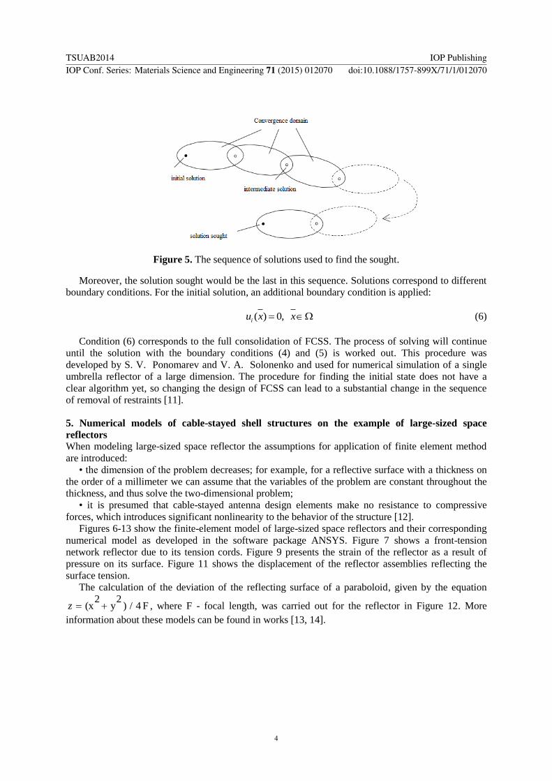
Figure 5. The sequence of solutions used to find the sought.
Moreover, the solution sought would be the last in this sequence. Solutions correspond to different
boundary conditions. For the initial solution, an additional boundary condition is applied:
( ) 0,iu x x (6)
Condition (6) corresponds to the full consolidation of FCSS. The process of solving will continue
until the solution with the boundary conditions (4) and (5) is worked out. This procedure was
developed by S. V. Ponomarev and V. A. Solonenko and used for numerical simulation of a single
umbrella reflector of a large dimension. The procedure for finding the initial state does not have a
clear algorithm yet, so changing the design of FCSS can lead to a substantial change in the sequence
of removal of restraints [11].
5. Numerical models of cable-stayed shell structures on the example of large-sized space
reflectors
When modeling large-sized space reflector the assumptions for application of finite element method
are introduced:
• the dimension of the problem decreases; for example, for a reflective surface with a thickness on
the order of a millimeter we can assume that the variables of the problem are constant throughout the
thickness, and thus solve the two-dimensional problem;
• it is presumed that cable-stayed antenna design elements make no resistance to compressive
forces, which introduces significant nonlinearity to the behavior of the structure [12].
Figures 6-13 show the finite-element model of large-sized space reflectors and their corresponding
numerical model as developed in the software package ANSYS. Figure 7 shows a front-tension
network reflector due to its tension cords. Figure 9 presents the strain of the reflector as a result of
pressure on its surface. Figure 11 shows the displacement of the reflector assemblies reflecting the
surface tension.
The calculation of the deviation of the reflecting surface of a paraboloid, given by the equation
2 2(x y ) / 4 Fz , where F - focal length, was carried out for the reflector in Figure 12. More
information about these models can be found in works [13, 14].
TSUAB2014 IOP PublishingIOP Conf. Series: Materials Science and Engineering 71 (2015) 012070 doi:10.1088/1757-899X/71/1/012070
4

Figure 6. Umbrella type reflector with aperture
of 50 m.
Figure 7. Strain of front reflector network, Pa.
Figure 8. Inflatable reflector with aperture of 50
m.
Figure 9. Reflector strain.
Figure 10. Reflector with flexible spokes with
aperture of 50 m.
Figure 11. Displacement of reflector assemblies,
m.
Figure 12. Reflector with tensegritied rim with
aperture of 48 m.
Figure 13. Distribution of deviations from the
reflecting surface of paraboloid where RMSD is
4,05∙10-3
m.
TSUAB2014 IOP PublishingIOP Conf. Series: Materials Science and Engineering 71 (2015) 012070 doi:10.1088/1757-899X/71/1/012070
5

All the numerical models are developed by using the approach proposed in Section 4. For all
prescribed designs and initial solutions were predetermined zero boundary conditions on the
displacement of assemblies. Further, to obtain the intermediate solutions, these boundary conditions
for part of the assemblies are not predetermined, and the process continued until the solution sought
was found. The main reason for its use is the large geometric nonlinearity arising in cable-stayed shell
structures.
6. Conclusion
The problem of cable-stayed shell structures applicability was considered to generate innovative
designs in building industry. The technique of numerical solution of the problem of stress-strain state
of structures with high geometric nonlinearity was developed. The effectiveness of the developed
technique is shown in a number of designs of large-sized space antenna reflectors.
References
[1] Fuller and Buckminster R 1982 (MacMillan Publishing Co. Inc 876)
[2] Levin S 2006 Textbook of Musculoskeletal Medicine (Oxford University Press)
[3] Gomez-Jauregui 2010 296
[4] Tibert A 2002 Doctor Thesis Royal Institute of technology SE-100 44
[5] Lewis W 2003Tension Structures. Form and Behaviour (Thomas Telford: London) 201
[6] Morterolle S, Maurin B, Quirant J and Dupuy C 2012 Numerical form-finding of geotensoid
tension truss for mesh reflector Systèmes Acta Astronautica 76 154
[7] Correa J 2001 Static Analysis of Tensegrity Structures (University of Florida) 218
[8] Murakami H 2001 Int J Solids Struct 38 3599
[9] Murakami H 2001 Int J Solids Struct 38 3615
[10] Zhukov A, Ponomarev V and Ponomarev S 2011 Universities bulletin. Physics 54 10/2154
[11] Zhukov A and Ponomarev S 2012 Universities bulletin. Physics 55 7/2 72
[12] Yashchuk A 2005 Thesis... Cand. Sc. Tomsk State University
[13] Belov S, Bel'kov A, Evdokimov S, Zhukov A, Pavlov M, Ponomarev S, Ponomarev V,
Solonenko V and Yashchuk A 2012 Universities bulletin. Physics 55 9/13
[14] Velichko A, Belov S and Ponomarev S 2013 Universities bulletin. Physics 56 7/3143
TSUAB2014 IOP PublishingIOP Conf. Series: Materials Science and Engineering 71 (2015) 012070 doi:10.1088/1757-899X/71/1/012070
6

Corrigendum: Stress-strain state simulation of large-sized
cable-stayed shell structures
S Ponomarev1, A Zhukov1, A Belkov1, V Ponomarev1, S Belov1 and
M Pavlov1 1National Research Tomsk State University, Research Institute of Applied Mathematics
and Mechanics,Tomsk, 634050, Russia
*E-mail: [email protected]
CORRIGENDUM TO: 2015 IOP Conf. Ser.: Mater. Sci. Eng. 71 012070
Acknowledgements
This work has been supported by the Russian Ministry of Education, a unique identifier
RFMEFI57814X0073.
The authors would like to include the following acknowledgements, which were omitted from the original paper.