herramientas de diseño para iluminacion en arquitectura.
57
T21/C4-10/GER/98-05 Survey Simple Design Tools A Working Document of TASK 21 / ANNEX 29 May 1998 Position of the Sun for Cologne 0 10 20 30 40 50 60 70 -180 -170 -160 -150 -140 -130 -120 -110 -100 -90 -80 -70 -60 -50 -40 -30 -20 -10 0 10 20 30 40 50 60 70 80 90 100 110 120 130 140 150 160 170 180 Sun Azimuth Sun Altitude East West South 5.Ja 4.Feb 21.De 5.Apr 5.Mai 4.Juni 18.No 19.Okt 19.Sep 20.Au 21.Juli 21.Jun 12° 10° ° 8°° 6°° 14° ° 16° 18° 6.März
-
Upload
erik-parraguez -
Category
Documents
-
view
228 -
download
0
description
Documento de Referencia
Transcript of herramientas de diseño para iluminacion en arquitectura.
T21/C4-10/GER/98-05
Survey Simple Design Tools
A Working Document of TASK 21 / ANNEX 29May 1998
Position of the Sun for Cologne
0
10
20
30
40
50
60
70-1
80
-170
-160
-150
-140
-130
-120
-110
-100 -90
-80
-70
-60
-50
-40
-30
-20
-10 0 10 20 30 40 50 60 70 80 90 100
110
120
130
140
150
160
170
180
Sun Azimuth
Sun
Alti
tude
EastWest South
5.Ja
4.Feb
21.De
5.Apr
5.Mai
4.Juni
18.No
19.Okt
19.Sep
20.Au
21.Juli
21.Jun
12°
10°°
8°°
6°°
14°°
16°
18°
6.März


IEA SHC TASK 21 / ECBCS ANNEX 29, Survey Simple Design Tools
This survey was prepared as an account of work sponsored by the Governmentof the Federal Republic of Germany and the ADELINE Users Club.Neither the Federal Republic of Germany, nor the ADELINE Users Club, nor theInternational Energy Agency, nor any of their employees, nor any of their contrac-tors, subcontractors, or their employees makes any warranty, express or implied,or assumes legal liability or responsibility for the accuracy, completeness or use-fulness of any information, apparatus, product or product disclosed, or repre-sents that its use would not infringe privately owned rights.
This survey was printed and is available from
Fraunhofer-Institut für BauphysikNobelstr. 1270569 Stuttgart, GermanyFax: +49-711-970-3399 T21/C4-10/GER/98-05

IEA SHC TASK 21 / ECBCS ANNEX 29, Survey Simple Design Tools
IEA SHC TASK 21 / ECBCS ANNEX 29
DAYLIGHT IN BUILDINGS
SUBTASK C4: SIMPLE DESIGN TOOLS
Working Document ‘Survey Simple Design Tools’
Jan de Boer, Hans ErhornFraunhofer Institute for Building Physics,Nobelstraße 1270569 StuttgartGermany

IEA SHC TASK 21 / ECBCS ANNEX 29, Survey Simple Design Tools
DISTRIBUTION CLASSIFICATION: UNRESTRICTED

IEA SHC TASK 21 / ECBCS ANNEX 29, Survey Simple Design Tools Preface
PREFACE
The International Energy Agency (IEA) was established in 1974 within the framework ofthe Organisation for Economic Cooperation and Development (OECD) to implement anInternational Energy Programme. A basic aim of the IEA is to foster cooperation amongthe 24 IEA Participating Countries to increase energy security through energyconservation development of alternative energy sources and energy research,development and demonstration (R&D).
Initiated in 1977, the IEA Solar Heating and Cooling Programme (IEA SHC) was one ofthe first collaborative R & D agreements to be established. The participating countriescarry out a variety of projects intended to advance active solar, passive solar, and solarphotovoltaic technologies for building applications. Nineteen countries plus theEuropean Community are members of the Solar Heating and Cooling Programme:
Australia Germany SwedenAustria Italy SwitzerlandBelgium Japan TurkeyCanada The Netherlands United KingdomDenmark New Zealand United StatesFinland NorwayFrance Spain
Since the formation of the programme, a total of twenty four projects (called [Research]Tasks) have been initiated. Most are completed. The Programme usually consists of amuch smaller number of active tasks. Each of the tasks is managed by an OperatingAgent from one of the participating countries. The overall control of the program restswith an Executive Committee comprised of one representative from each contractingparty to theagreement. In addition, a number of special ad hoc activities - workinggroups and seminars - have also been established.
In recognition of the significance of energy use in buildings, the International EnergyAgency has established an Implementing Agreement on Energy Conservation inBuildings and Community Systems (ECBCS) in 1976. This is aimed at initiatingresearch and providing an international focus for building energy efficiency. Tasks aredirected at generic energy saving technologies and activities that support theirapplication in practice. Results are also used both nationally and internationally todevelop relevant standards and guidelines. Member organisations of the ECBCS aredrawn from a total of 22 Countries:
Australia Greece PortugalBelgium Italy SwedenCanada Israel SwitzerlandCEC Japan Turkey

IEA SHC TASK 21 / ECBCS ANNEX 29, Survey Simple Design Tools Preface
Denmark The Netherlands United KingdomFinland New Zealand United StatesFrance NorwayGermany Poland
Participation in any particular programme of research is optional and, most commonly,takes the form of a 'task shared' Annex. Each participant agrees to commit an agreedamount of resources to such Annexes which operate, typically, for a four year period.Occasionally an Annex may be jointly funded, in which case a single institutionreceives funding from Annex participants to undertake an agreed work programme.
The main objectives of the IEA SHC Program Task 21 and the ECBCS ProgramAnnex 29 "Daylight in Buildings" are to advance daylighting technologies and topromote daylight conscious building design. Task 21 continues until August 1999, andwill endeavour to overcome the barriers that are impending the appropriate integrationof daylighting aspects in building design. The participants in this task are Australia,Austria, Belgium, Canada, Denmark, Finland, France, Germany, Italy, Netherlands,New Zealand, Norway, Sweden, Switzerland, United Kingdom and the United States.Denmark is the Operating Agent.
The objective of Subtask C "Daylighting Design Tools" of Task 21 is to improve thecapability, accuracy and ease-of-use of daylighting design and analysis tools forbuilding design practitioners, covering all phases of the design process. Thepractitioners will be able to predict the performance of different daylighting systems andcontrol strategies and to evaluate the impact of the integration of daylighting in theoverall building energy concept by using these design tools. Subtask C is devided into5 Subgroups:
C1: ValidationC2: New Daylight AlgorithmsC3: Integrated SystemsC4: Simple Design ToolsC5: ADELINE 3.0.
This "Survey on Simple Design Tools" was initiated and compiled within Subgroup C4.

IEA SHC TASK 21 / ECBCS ANNEX 29, Survey Simple Design Tools Executive Summary
EXECUTIVE SUMMARY
The document presents work conducted as part of Subtask C, ’’Daylighting DesignTools“, Subgroup C4, ’’Simple Design Tools“, of the IEA SHC Task 21 and the ECBCSProgram Annex 29 ’’Daylight in Buildings“.
Beside the further development and promotion of powerful daylighting design tools -being one of the major scopes of Subtask C - the emphasise has also been placed onsimple design tools. For early design stages (outlining the basic daylighting strategy)and the solution of reoccuring simple problems (e.g. the sunshine duration atconsidered spots or a general decision about the type of rooflights to select), complexsimulations are not necessary and, from a practioner s point of view, take often toomuch time which renders them too expensive. This survey gives as a collection across-section of various types of simple daylighting design tools and of the differentfields of applications. Tools based on analytical solutions, tables, nomograms,diagrams, so- called protractors, simple computer tools, typological studies, and alsothe method of using scale models are being described. They provide support at thevarious stages of the design process helping to judge the impact of the design onnatural lighting conditions: building site and building layout planning (i.e. sunshineduration at considered spots, shadow and reflection analysis), typological support forthe selection of a daylighting strategy, determination of the type and size of daylightopenings and the corresponding daylight factors for differently daylit rooms, as well asenergetic aspects of lighting design.
Beside a number of basic and already well-known tools a couple of new design toolsdeveloped recently by institutes participating in the Task were included. To allow forproblem-sensitive selection, the survey includes a tabular overview characterising thereviewed tools.

IEA SHC TASK 21 / ECBCS ANNEX 29, Survey Simple Design Tools

IEA SHC TASK 21 / ECBCS ANNEX 29, Survey Simple Design Tools Contents
1
CONTENTS
1 INTRODUCTION .......................................................................................................2
2 REVIEWED TOOLS ..................................................................................................4
2.1 Formulae2.1.1 Dimensions of Rooflights ................................................................................62.1.2 Daylight Factor, Internal Reflected Component..............................................8
2.2 Tables2.2.1 Minimum Window Sizes for Dwellings ..........................................................102.2.2 Daylight Factors for Rooflit Spaces ..............................................................12
2.3 Nomograms2.3.1 Daylight Factor, Internal Reflected Component............................................142.3.2 Atrium Layout................................................................................................16
2.4 Diagrams2.4.1 Horizontoscope: Sunshine Duration etc. ......................................................182.4.2 Waldram Diagram, Direct Sky Component ...................................................202.4.3 Daylight Autonomy........................................................................................222.4.4 Lighting Switch-On Hours .............................................................................24
2.5 Protractors2.5.1 B.R.S. Daylight Protractors...........................................................................26
2.6 Computer Tools2.6.1 Daylight Calculations for Shoebox-Type Rooms ..........................................282.6.2 Shadow and Reflection Analysis ..................................................................302.6.3 Spreadsheets: Collection of Equations and Diagrams .................................322.6.4 Solar Light Factors for Dynamic Lighting Control .........................................342.6.5 DIAL: Qualitative and Quantitative Daylighting Design ................................36
2.7 Typology2.7.1 Typological Study of Various Test Rooms....................................................38
2.8 Scale Models2.8.1 Artificial Skies / Artificial Sun ........................................................................40
3 CHARACTERIZATION OF THE REVIEWED TOOLS ............................................42
4 LIST OF CONTACT PERSONS..............................................................................44

IEA SHC TASK 21 / ECBCS ANNEX 29, Survey Simple Design Tools Introduction
2
1 INTRODUCTION
The big share of problems in lighting design - artificial- as well as daylighting - cannowadays be treated and solved with simulation software. Depending on the complexityof the problem, the stage of the building design process, the resired accuracy, as wellas quality of the output information, the application of these more sophisticated tools isoften the only way to pursue. Nevertheless these tools normally ask for detailedmodelling, require a thorough knowledge of the programs, and often demand highcomputational power. Although the modelling processes have been quite simplifiedover the last years, they still can be rather time-consuming.
For early design stages (outlining the basic daylighting strategy) and the solution ofreoccuring simple problems (e.g. the sunshine duration at considered spots or ageneral decision about the type of rooflights to select), complex simulations are notnecessary and, from a practioner s point of view, take often too much time whichrenders them too expensive.
The development of simple design tools has been, and still is, motivated by a numberof reasons:• Historically, due to the need to approach daylighting problems (without the support
of computer technology being available), a number of simple tools, often closelytailored to practioner’s needs has evolved. These tools deliver fast and generallysufficiently accurate results; most of them have been well-tested and validated.
• Simple design tools like tables, nomograms etc. are often the outcome of a‘’knowlegde compression“ from complex parametric studies. The required data arefor example obtained from model studies under artificial skies or by using numerouscomputer program runs. The interdependence of design parameters can then quicklybe studied by for instance pursuing for atria design certain paths of boundaryconditions in a nomogram, and then finally giving the daylight factors in the adjacentoffices. These tools are representing condensed experience; the parametricvariations do not have to be performed all over again by the user of the tools.
• With computers being available on almost every workplace, a number of simplecomputer tools has been developed and is in use nowadays. Simple programs orsimple parametric inputs to more sophisticated tools deliver fast solutions for specificproblems, while keeping modelling efforts and computation time limited. These areespecially suited for performing own simple variations of parameters (e.g. varyingthe window size and placement). The implementation of equations in spreadsheetsand their ‘’display“ in diagrams with programs like MS-EXCEL, is fast and convenientto use.
With hundreds of design tools existing in the field of daylighting, this survey does notand cannot pretend to cover all available and developed tools. It rather gives as acollection a cross-section of various types of tools and of the different fields ofapplications. Tools based on analytical solutions, tables, nomograms, diagrams, socalled protractors, simple computer tools, typological studies, and also the method of

IEA SHC TASK 21 / ECBCS ANNEX 29, Survey Simple Design Tools Introduction
3
using scale models are being described. They provide support at the various stages ofthe design process helping to judge the impact of the design on natural lighting
conditions: building site and building layout planning (i.e. sunshine duration at con-sidered spots, shadow and reflection analysis), typological support for the selection ofa daylighting strategy, determination of the type and size of daylight openings and thecorresponding daylight factors for differently daylit rooms, as well as energetic andthermal aspects of lighting design.
Feedback from a questionaire distributed to the participants of IEA SHC TASK 21 hasbeen integrated. A number of newly developed tools could thus be included. Altogether18 tools are presented and discussed.
For a problem-sensitive selection of tools, the survey includes a tabluar charaterizationaccording to a set of attributes which account for the requested input, obtainable outputetc...
IEA SHC TASK 21 / ECBCS ANNEX 29, Survey Simple Design Tools Reviewed Tools
4
2 REVIEWED TOOLS
Each tool is reviewed according to Author/Source, Subject, Description, Discussion,Reference, and Example. The Description part presents the method, requested inputparameters, and obtainable output. In the tool Discussion general comments on thetools are given. Restrictions in the applications are pointed out. Some of the reviewedtools are for instance in the version, in which they are presented, only applicable underdefined boundary conditions, i.e. certain sites and climates, or being subject to nationalregulations. Nevertheless, by being aware of these restrictions a simple transition toother conditions is in most cases possible.
Finally, for each tool an Application Example, containing examplarily solutions ofequations, use of graphics or nomograms, excerpts of data tables, output fromcomputer tools etc. is included. Hereby the specific features, the restrictions, as well asan impression of the time to apply a tool is conveyed.
For a fast selection of the tools reviewed, a classification according to tool type and totool subject is included at the beginning of this section. The matrix allows for cross-referencing between type and subject of the reviewed tools, i.e for a chosen type thedetermination of the covered subjects, and vice versa. For a more detailledcharacterization refer to section 3.

IEA SHC TASK 21 / ECBCS ANNEX 29, Survey Simple Design Tools Reviewed Tools
5

IEA SHC TASK 21 / ECBCS ANNEX 29, Survey Simple Design Tools Formulaef(x)
6
2.1.1 DIMENSIONS OF ROOFLIGHTS
Author / SourceGerman Industrial Standard, DIN 5034
SubjectSimplified determination of suitable rooflight dimensions for a given mean daylightfactor.
DescriptionFor a given mean daylight factor this method calculates from1. the reflectances of the room surfaces,2. the room dimensions,3. the glazing parameters (transmission, framing factor, and dirt-on-glazing factor),4. and the type of rooflight with the geometric parameters of the light wellsthe necessary total rooflight area. From this total area and the number of desiredrooflights, the depth as well as the width of the single rooflights can be determined.Among the five types of supported rooflights are saddle rooflights, 60° as well as 90°roofmonitors.
DiscussionDue to a simple characterisation of different rooflights, the method allows for a quickcomparison of different rooflight types in the early design phase. Since it assumes anumber of simplifications and is partly based on fixed parameters, certain restrictions inthe accuracy of the results apply. The influence of interreflections from the room’s sidewalls is for instance neglected. Since the tool is based on a free selectable daylightfactor, the method can easily be applied for other than German conditions. It is limitedto rectangular floor plans.
References• German Industrial Standard, DIN 5034, Daylight in Interiors, part 6, Simplified
determination of suitable dimensions for rooflights, DIN, Deutsches Institut fürNormung e. V., 1996.

IEA SHC TASK 21 / ECBCS ANNEX 29, Survey Simple Design Tools Formulaef(x)
7
Application Example
The tool requires a set of geometric parameters defining a shoebox-type space.Examplarily values are printed in italics:
Section 1 Section 2 Standard Rooflight
The rooflight geometry is described according to the selected type, here a standardrooflight. Corresponding descriptions are available for other rooflight types.
From the following input parameters
Parameter Description Examplary Valuek1 Framing factor, accounting for structural rooflight elements: 0.8k2 Dirt-on-glazing factor: 0.8k3 Factor for not normal light transmission from the sky: 0.85k4 Factor for geometric shape and reflection of rooflight well: 0.92
τD65 Transmission of rooflight glazing: 0.6ρD Reflection of light well: 0.55ρC Reflection of the ceiling: 0.7ρF Reflection of the floor: 0.2ϑa Factor accounting for finite room width geometry f(ϕa): 0.76ϑb Factor accounting for finite room length geometry f(ϕb): 0.88
the necessary total rooflight area A (work measurement) to get a required meanworksurface daylight factor of for instance D = 5 % is obtained by the formula
AD a b
k k k kD a b
F C
F C
= ⋅ ⋅⋅ ⋅ ⋅ ⋅ ⋅ ⋅ ⋅ ⋅ +
⋅− ⋅
−
τ ϑ ϑρ ρ
ρ ρ65 1 2 3 4
1
1001
1= 42.6 m2.
From the area A with a given number n of desired rooflights the length ar and width br ofthe single rooflight can be determined:
Number of Rooflights Desired Width Resulting Lengthn = 10 br= 0.61 m ar = A/(n*br) = 7 m
IEA SHC TASK 21 / ECBCS ANNEX 29, Survey Simple Design Tools Formulaef(x)
8
2.1.2 DAYLIGHT FACTOR, INTERNAL REFLECTED COMPONENT
Author / SourceGerman Industrial Standard, DIN 5034
SubjectInternal reflected component of the daylight factor for side- and rooflit rooms.
DescriptionThe daylight factor can be separated into three components: the direct sky componentDsky, a component caused by the visible part of outside obstructions Dobst. and aninternally reflected component Drefl : D = Dsky + Dobst + Drefl . The direct component canbe obtained with a variety of tools (BRE daylight factor protractors → tool 2.5.1,Waldram diagrams → tool 2.4.2, etc.).The equation given for the computation of the internal reflected component accountsfor the luminous flux (separate angular description for the flux share above the outdoorobstruction and a share resulting from reduced luminances caused by the obstructionitself), window size, room surface area and corresponding mean reflection coefficients.The basic method accounts for the raw window opening. For the selected windowembedded in the opening the obtained Drefl is weighted with glazing parameters (i.elight transmission, dirt-on-glazing factor, etc). The method is suited for windows in morethan one wall. A simplified version exists for rooflit rooms.
DiscussionIn contrast to the determination of the direct sky components this equation can onlyprovide a mean daylight factor component. For investigated spots behind one half ofthe room depth the used mean reflection coefficients have to be substituted by theroom`s minimum reflection coefficient. The angular obstruction description can handleonly obstructions that are even. For strong variations in the masking geometry meanangular values have to be used. There might be cases where this averaging does notlead to sufficient results.
References• German Industrial Standard, DIN 5034, Daylight in Interiors, part 3, Calculation,
Calculation of the indirect component of the daylight factor, DIN, Deutsches Institutfür Normung e. V., 1996.
• Udo Fischer, Tageslichttechnik, Verlagsgesellschaft Rudolf Müller GmbH, Köln,1982.

IEA SHC TASK 21 / ECBCS ANNEX 29, Survey Simple Design Tools Formulaef(x)
9
Application Example
From the following input parameters
Parameter Description Examplary ValueΣ bF hF Sum of window area (here: height 1.7 m, width: 2.2 m) 3.74 m²
Ar Sum of room surface areas(here: height: 2.5 m, width: 4 m, depth: 3.5 m)
65.5 m²
ρ Mean Reflectance of all wall surfaces 0.45ρfw Mean Reflectance of floor and lower parts of the walls
without wall containing window0.4
ρcw Mean Reflectance of ceiling and upper parts of the wallswithout wall containing window
0.6
α Obstruction angle 0°fu(α) Window factor, function of the external luminous flux
incident onto the window from the upper hemisphere,dependent of obstruction angle α
0.319
fl(α) Window factor, function of the external luminous fluxincident onto the window from the lower hemisphere,dependent of obstruction angle α
0.067
The internal reflected component of the daylight factor is obtained by the formula:
Db h
Af frefl
f
ru fw l cw. ( )= • − • ⋅ + ⋅ •
∑ ρρ ρ ρ
1100%2 = 0.54 %

IEA SHC TASK 21 / ECBCS ANNEX 29, Survey Simple Design Tools Tables
10
2.2.1 MINIMUM WINDOW SIZES FOR DWELLINGS
Author / SourceGerman Industrial Standard, DIN 5034
SubjectSimplified determination of minimum window sizes for dwellings.
DescriptionApplicable to rooms daylit from one vertical, rectangular window this method providesthe minimum window size in order to obtain a mean daylight factor of 0.9 % on the axisin the middle of the room (room depth) at an height of 0.85 m.Depending on 4 parameters:
Linear outside obstruction (angular range): 0°- 50°Height of the room: 2.4 m - 3 mwith a corresponding varying window height: 1.35 m - 1.85 mRoom width: 2 m - 8 mRoom depth: 3 m - 8 m
the necessary window width is provided in tabular form. The minimum window width isassumed to be 55 % of the room width (corresp. to German regulation).
DiscussionMany design parameters like wall reflectances, glazing characteristics, height of thewindow sill, and the geometrical shape of an obstruction are fixed. The method isbased on a daylight factor which has been found sufficient for German conditions. It isthus only suited for countries with similar geographic and climatic conditions.Nevertheless, recommendations for minimum window sizes are common in othercountries. National lighting societies (or similar organisations) should be consulted.
References• German Industrial Standard, DIN 5034, Daylight in Interiors, part 4, Simplified
determination of window sizes for dwellings, DIN, Deutsches Institut für Normung e.V.,1994.

IEA SHC TASK 21 / ECBCS ANNEX 29, Survey Simple Design Tools Tables
11
Application Example
Room Section with Angular Description of Obstruction
Examplary table: obstruction angle, α = 30 °; room height, h = 2.7 m; window height, hF = 1.55 m
α h b Minimum Window Width bw for a given Room-Depth a
3,00 3,25 3,50 3,75 4,00 4,25 4,50 4,75 5,00 5,25 5,50 5,75 6,00 6,25 6,50 6,75 7,00 7,50 8,00
30 2,70 2,00 1,31 1,34 1,51 1,61 1,69 1,78 1,86 1,95
(hF= 2,50 1,64 1,75 1,86 1,96 2,06 2,16 2,26 2,36 2,45
1,55) 3,00 1,97 1,98 2,11 2,22 2,34 2,46 2,57 2,68 2,79 2,91
3,50 2,30 2,37 2,50 2,63 2,76 2,89 3,01 3,14 3,27 3,40
4,00 2,63 2,64 2,78 2,93 3,07 3,21 3,36 3,50 3,64 3,78
4,50 2,96 3,07 3,23 3,38 3,54 3,70 3,85 4,01 4,17 4,48
5,00 3,29 3,37 3,54 3,71 3,88 4,05 4,22 4,39 4,56 4,90
5,50 3,62 3,68 3,86 4,04 4,22 4,40 4,59 4,77 4,96 5,33
6,00 3,94 4,00 4,19 4,38 4,57 4,77 4,96 5,16 5,36 5,76
6,50 4,27 4,32 4,52 4,72 4,93 5,14 5,34 5,55 5,77 6,20
7,00 4,60 4,86 4,86 5,07 5,29 5,51 5,73 5,95 6,18 6,63
7,50 4,93 5,20 5,20 5,43 5,65 5,88 6,12 6,35 6,59 7,07
8,00 5,26 5,55 5,55 5,78 6,02 6,27 6,51 6,76 7,01 7,52
For a linear horizontal outside obstruction seen under an angle of 30° from the windowpane, a room height of 2.7 m, a window height of 1.55 m, a room width of 5.5 m, and aroom depth of 6.0 m a minimum window width of 4,22 m is required. The obtainedwindow size is a minimum requirement providing a mean daylight factor of 0.9 % on anaxis in half the room depth.

IEA SHC TASK 21 / ECBCS ANNEX 29, Survey Simple Design Tools Tables
12
2.2.2 DAYLIGHT FACTOR FOR ROOFLIT SPACES
Author / SourceGerman Industrial Standard, DIN 5034
SubjectDetermination of mean daylight factors in rooms with rooflights.
DescribtionThe tool is based on the utilization factor method known from artificial lighting. Fordifferent combinations of room index (i.e. function of room height, depth, and width) andthe reflectances of room surfaces the utilization factor for two different types ofrooflights can be obtained from tables as functions of a set of geometric parameters:
Standard Rooflights Shed RooflightsIncline of rooflight wells (30°, 60°,90°), Size of rooflight openingRatio depth to width and ratio height to width Incline of non-glazed shed sideThe resulting well index Incline of glazed side.
The mean daylight factor is then calculated as a function of the determined utilizationfactor.
DiscussionThe method delivers only mean daylight factors. Values for single points cannot beobtained. The tables allow for useful variations of design parameters for two verycommon rooflight types. The method is not restricted to German conditions.Recommendations for daylighting with rooflights are common in other countries.National lighting societies (or similar organisations) should be consulted for existingsimilar methods.
References• German Industrial Standard, DIN 5034, Daylight in Interiors, part 3, Calculation, DIN,
Deutsches Institut für Normung e. V., 1994.

IEA SHC TASK 21 / ECBCS ANNEX 29, Survey Simple Design Tools Tables
13
Application Example
For a room length a = 20 m, width b = 10 m, height h = 5.30 m the room index isobtained:
kb a
h b a= ⋅
⋅ +≈
( )1.25 .
The method can cope with two rooflight types. Type A is selected for this example.
Type A, Standard Rooflight Type B, Shed Rooflight
The utilisation factor η[%] is determined from tables as a function of reflectioncoefficients, obtained room index k, and the rooflight geometry: η = 68 %.
Examplary Table: η (utilization factor) in % for ar / br = 1; hr / br = 0,25; γ = 90°, w = 0,25
ρD 0,8 0,8 0,8 0,5 0,5 0,8 0,8 0,8 0,5 0,5 0,3 0ρW 0,8 0,5 0,3 0,5 0,3 0,8 0,5 0,3 0,5 0,3 0,3 0ρB 0,3 0,3 0,3 0,3 0,3 0,1 0,1 0,1 0,1 0,1 0,1 0k
0,6 64 40 32 38 26 49 38 31 36 26 23 160,8 75 53 44 50 37 57 49 42 48 36 32 241,0 81 59 50 55 41 60 54 47 52 40 35 27
1,25 88 68 59 64 49 65 62 56 60 47 41 321,5 93 74 66 69 54 68 67 61 65 51 45 362,0 98 83 75 77 61 71 74 69 71 57 51 402,5 102 88 81 81 65 73 78 73 75 61 54 433,0 104 92 86 85 68 75 81 77 78 63 56 454,0 107 98 93 89 73 76 85 81 82 67 59 485,0 109 101 97 92 75 77 87 84 84 69 61 49
A so-called ‘outside daylight factor’ Dout= Eplane / Eext (ratio of illuminance on inclinedplanes to horizontal external illuminance under a CIE overcast sky) is determined:Dout = 1, for the here chosen standard rooflight type. With a planned total area of ceilingopenings (work measurement) A = 81 m2
and additional parameters: glazingtransmission τD65 = 0.85, framing factor k1 = 1, dirt-on-glazing factor k2 = 0.9, correctionfactor for not normal light penetration from the overcast sky onto the glazing panek3 = 0.85, and the total area of room surfaces Asurf = 720 m2, the mean daylight factorfor this test room is obtained:
D D k k kA
Aout Dsurf
= ⋅ ⋅ ⋅ ⋅ ⋅ ⋅ =∑τ η65 1 2 3 100% 5 %
IEA SHC TASK 21 / ECBCS ANNEX 29, Survey Simple Design Tools Nomograms
14
2.3.1 DAYLIGHT FACTOR, INTERNAL REFLECTED COMPONENT
Author / SourceR.G. Hopkinson, J. Longmore, P. Petherbridge
SubjectNomogram for the determination of the internal reflected component of the daylightfactor.
DescriptionThe daylight factor can be separated into three components: the direct sky componentDsky, a component caused by the visible part of outside obstructions Dobst and aninternally reflected component Drefl :
D = Dsky + Dobst + Drefl .The direct component and the component from possible obstructions can be obtainedwith a variety of tools (BRE daylight factor protractors → tool 2.5.1, Waldram diagrams→ tool 2.4.2, etc.). This tool is based on a nomogram derived from a simple equation inwhich the daylight factor’s internal reflected component is calculated as a function ofthe size of the window opening, the total room surface areas, an utilization factor(known from artificial lighting calculations), which accounts for the surface reflectionsand surface ratios, as well as an outside obstruction angle. The utilization factor can beobtained from a separate chart. For a specified window embedded in the daylightopening (work measurement) the obtained Drefl is weighted with the window parameters(i.e. light transmission, dirt-on-glazing factor, etc.).
DiscussionIn contrast to the determination of the direct sky component, the nomogram can onlyprovide a mean daylight factor component. Only simple linear obstructions can behandled; for bigger variations in the obtructions’ geometry mean angular values have tobe taken. The remaining components, dfsky and dfobst, have to be calculated using othermethods. With nomograms of this type it is possible to treat vertical, tilted, andhorizontal glazing layers (therefore also rooflights). Furthermore nomograms for theinternal reflected component exist, which allow to analyse clear skies.
References• R.G. Hopkinson, J. Longmore, P. Petherbridge, ‘’An Empirical Formula for the
Computation of Indirect Component of the Daylight Factor’’, Trans. IES, vol. 19,No. 7, 1954.
• Udo Fischer, Tageslichttechnik, Verlagsgesellschaft Rudolf Müller GmbH, Köln,1982.
IEA SHC TASK 21 / ECBCS ANNEX 29, Survey Simple Design Tools Nomograms
15
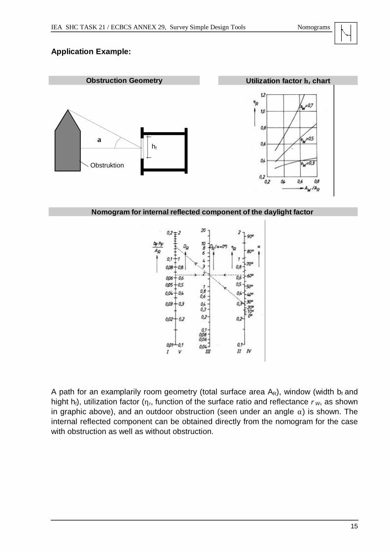
Application Example:
Obstruction Geometry Utilization factor ηr chart
Nomogram for internal reflected component of the daylight factor
A path for an examplarily room geometry (total surface area AR), window (width bf andhight hf), utilization factor (ηr, function of the surface ratio and reflectance ρW, as shownin graphic above), and an outdoor obstruction (seen under an angle α) is shown. Theinternal reflected component can be obtained directly from the nomogram for the casewith obstruction as well as without obstruction.
α
Obstruktion
hf
IEA SHC TASK 21 / ECBCS ANNEX 29, Survey Simple Design Tools Nomograms
16
2.3.2 ATRIUM LAYOUT
Author / SourceM. Szerman, Fraunhofer Institute for Building Physics
SubjectNomogram for daylight factors in offices adjacent to atria.
DescriptionThis tool provides a fast estimation of the mean daylight factors in rooms adjacent tolinear atria. For a fixed office geometry (window / facade ratio 60 %, width: 3.5 m,depth: 4.8 m, and height: 2.7 m) and fixed reflectances of the office surfaces (floor:15 %, walls: 50 %, and ceiling: 70 %) mean daylight factors can be obtained graphicallyfor a range of atrium design parameters:
Office position: Ground , middle, or top floorRatio of atrium height to depth 0.4 - 1.6Reflectance of opaque atrium walls: 0 % - 70 %Reflectance of atrium floor: 15 % - 70 %Glazing of atrium: Double / Low εGlazing of offices: Double / Low ε
DiscussionThe tool is a single stage method limited to linear atria. It delivers only mean daylightfactors for the considered office spaces. Nevertheless it is an easy to handle tool toquickly understand the influence of decisive atria design parameters on lightingsituations in connected workspaces. The data base used to generate the nomogramwas obtained from scale model measurements under an artificial sky.
References• Passive Solar Commercial and Institutional Buildings, A Sourcebook of Examples
and Design Insights, International Energy Agency, Paris, France, John Wiley& Sons Ltd., 1994

IEA SHC TASK 21 / ECBCS ANNEX 29, Survey Simple Design Tools Nomograms
17
Application Example
Nomogram, with exemplarily path and graphic showing the atria geometry
For a given set of design parameters:
Office Position: MiddleAtrium Width, w: 50 mAtrium Height, h: 12 mAtrium Depth, d 15 mRefl. Atrium Walls: 50 %Refl. Atrium Floor: 50 %Glazing Atrium: Low εGlazing Office: Low ε
A mean daylight factor of 2.4 % in the considered office is obtained by following thespecified path through the nomogram.
IEA SHC TASK 21 / ECBCS ANNEX 29, Survey Simple Design Tools Diagrams
18
2.4.1 HORIZONTOSCOPE: SUNSHINE DURATION etc.
Authors:F. Tonne
SubjectDetermination of sunshine duration, direct sky component of the daylight factor, heatpenetration.
DescriptionThe horizontoscope (a small acryl glass half dome with integrated compass) with acorresponding stereographic projection of the sun altitude and azimuth angle is appliedfor the on site determination of sunshine duration at selected outdoor or indoor spots.The standard sun path diagrams, available for all locations of uneven site latitudes,contain paths for summer and winter solstice, equinox, and average summer and winterdays. Sunshine durations are obtained from the charts by evaluating hourly intervalswhich are lying in the projection of the free, not occulted sky segments. In the designphase the acrylic halfdome of the horizontoscope can be substituted by a geometricalprojection of the daylight opening into another type of chart which is then superimposedonto the sun path diagram. The tool is able to account for any type of obstructions.Other available charts allow for the determination of the direct sky component of thedaylight factor and for the quick assessement of possible glare sources. Heat chartscan be used for quick estimations of solar heat penetration in indoor spaces as functionof facade orientation, facade incline, and used glazing.
DiscussionUseful tool for the quick on site and designing phase estimation of the sunshineduration. Estimations of the daylight factors takes only the direct component intoaccount. The internal reflected component has to be calculated using other methods(equation → tool 2.1.2, interreflected component nomograms → tool 2.3.1). For the useof the heat charts units have to be converted to SI units. The suggested glazing para-meters have to be crosschecked with data of glazings used nowadays.
References• Developed by F. Tonne. The tool is still distributed by the Institut für Tages-
lichttechnik, Eichgehrenweg 3, Stuttgart-Rohr, Germany.

IEA SHC TASK 21 / ECBCS ANNEX 29, Survey Simple Design Tools Diagrams
19
Application Example
Picture of Horizontoscope with Acrylichalfdome, compass, and sun path chart
Sunshine duration for a consideredpoint, obtained on site with the Hori-zontoscope
The projection of a window onto a screen-ing chart is determined on the drawingboard by geometrical construction
Determination of illuminance under anovercast sky on a horizontal plane, byevaluating the number of grids withinthe projected window. One grid elementcorresponds to 0.1 % daylight factor(only the direct sky component)

IEA SHC TASK 21 / ECBCS ANNEX 29, Survey Simple Design Tools Diagrams
20
2.4.2 WALDRAM DIAGRAM, DIRECT SKY COMPONENT
Author / SourceP.J. Waldram
SubjectDetermination of the direct sky component of the daylight factor.
DescriptionThe method is based on a projection of half the sky hemisphere onto a grid, which isconstructed such that equal areas of grid represent equal contributions from the sky tothe illumination at considered points. The diagrams are available for different skymodels (e.g. uniform sky, CIE overcast sky).Taken from scaled room plans and sections, the areas of sky and outdoor obstructionsvisible from a reference point are drawn into the diagram. The area enclosed by theseprojection lines corresponds to the graphical solution of the integral formula for thecalculation of the sky component based on a solid angle principle. The sky componentis then obtained by evaluating the projection area (of a window) within the diagram.
DiscussionDiagrams of this type allow to obtain the direct sky component for cases with complexoutdoor obstruction and window shapes. Window transmission losses are taken intoaccount. Additional methods have to be used to calculate the internal reflectedcomponent of the daylight factor (equation → tool 2.1.2, internal reflected componentnomograms → tool 2.3.1).
References• P.J. Waldram, A Measuring Diagram for Daylight Illumination, B.T. Batsford Ltd,
London, 1950.• Digest 309, Estimating daylight in buildings: Part 1, BRE, Garston, GB, 1986.• Udo Fischer, Tageslichttechnik, Verlagsgesellschaft Rudolf Müller GmbH, Köln,
1982.
IEA SHC TASK 21 / ECBCS ANNEX 29, Survey Simple Design Tools Diagrams
21
Application Example:
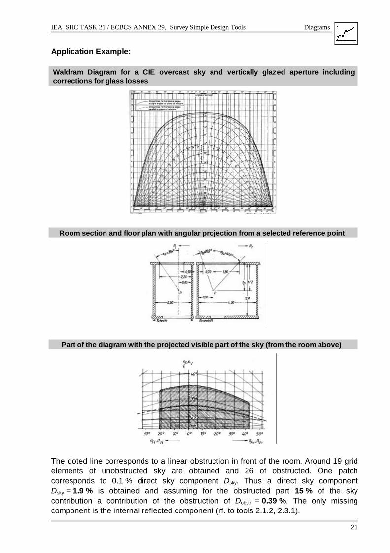
Waldram Diagram for a CIE overcast sky and vertically glazed aperture includingcorrections for glass losses
Room section and floor plan with angular projection from a selected reference point
Part of the diagram with the projected visible part of the sky (from the room above)
The doted line corresponds to a linear obstruction in front of the room. Around 19 gridelements of unobstructed sky are obtained and 26 of obstructed. One patchcorresponds to 0.1 % direct sky component Dsky. Thus a direct sky componentDsky = 1.9 % is obtained and assuming for the obstructed part 15 % of the skycontribution a contribution of the obstruction of Dobstr. = 0.39 %. The only missingcomponent is the internal reflected component (rf. to tools 2.1.2, 2.3.1).

IEA SHC TASK 21 / ECBCS ANNEX 29, Survey Simple Design Tools Diagrams
22
2.4.3 DAYLIGHT AUTONOMY
Author / SourceRecommendation of the Swiss Lighting Association, Swiss Norm SN 418911
SubjectDetermination of daylight autonomy.
DescriptionThis tool provides for a rated task illuminance and a given daylight factor the minimumoperating hours [%] during which a workplace can sufficiently and exclusively be lit withdaylight. The considered working hours are from 7 a.m. to 5 p.m. (or 8 a.m. to 6 p.m.).The considered period is one year.
DiscussionThe diagram is designed for Swiss conditions, i.e. the daylight autonomy as function ofdaylight factor and rated illuminance is based on outside illuminances according to theCIE sky for Swiss latitudes. Nevertheless, it is easily possible to generate correspon-ding diagrams for other latitudes. Since the daylight factor is defined as the worst case,it can be assumed that the daylight autonomy under real skies will be better than thehere obtained daylight autonomies. The chart represents values over a period of oneyear, thus averaged over all seasons.
References• Recommendation of the Swiss Lighting Association, Swiss Norm SN 418911,
Edited by Schweizerischer Elektrotechnischer Verein (SEV), CH-8008 Zürich,Seefeldstraße 301.

IEA SHC TASK 21 / ECBCS ANNEX 29, Survey Simple Design Tools Diagrams
23
Application Example
Operating times [%] with only daylight for working hours as function of the daylightfactor and rated workplace illuminance

IEA SHC TASK 21 / ECBCS ANNEX 29, Survey Simple Design Tools Diagrams
24
2.4.4 LIGHTING SWITCH-ON HOURS
Author / SourceM. Szerman, Fraunhofer Institute for Building Physics
SubjectMethod for estimation of lighting switch-on hours based on daylight factor and localweather data sets.
DescriptionAlthough for clear and partly cloudy skies not applicable, the daylight factor is still themost used daylighting design parameter. This simplified method derives 4 boundaryconditions for the relation between the daylight factor and artificial lighting switch-onhours. These constraints are obtained from local weather data sets and from workinghours. For a known daylight factor at a lighting control point the switch-on hours andtherefore the energy consumption of luminaires can be estimated.Boundary conditions for switch-on hours are obtained as follows:1. The upper limit, corresponding to a D1 = 0 %, is represented simply by the total sum
of working hours in the considered period.2. The lower limit is obtained by the time in the considered daily working intervals
where the exterior horizontal illuminance falls below the desired workplaceilluminance:
Eoutside < Etask. This definition implies D4 = 100 %.3. Lighting switch-on hours are only reduced if the illuminance through daylight
exceeds at least once the desired control point illuminance. In order to obtain switch-off hours at all, the daylight factor thus has to be bigger than:
D2= Etask / Emax,clear-sky with sun .4. Most of the time real sky conditions are some intermediate states between clear and
overcast skies. From overcast skies thus a fourth condition can be derived:D3 = Etask / Emax, overcast skies . Switch-on hours for D3 are then obtained by subtractingthe time, during which the constraint Eoutside > Etask / D3 is fulfilled, from the totalworking hours.
DiscussionAll boundary conditions derived here are independent of room geometries. Byevaluating for instance hourly local weather data, all 4 boundary conditions canapproximately be determined. Modelling of the boundary conditions involves a numberof uncertainties and assumptions. The use of this method should thus be restricted toquick estimates in early design stages.
References• M. Szerman, „Effects of daylight utilisation on the energetic behaviour of office
buildings“, Ph.D. thesis, University Stuttgart, 1994.

IEA SHC TASK 21 / ECBCS ANNEX 29, Survey Simple Design Tools Diagrams
25
Application Example:
General relation of daylight factor and switch-on hours of supplementary lighting
Relation of daylight factor and switch-on hours of supplementary lighting derived fromparamter study for a fixed German location
Working hours are Monday - Friday from 7 a.m.-4 p.m. [8 a.m.-5 p.m.] without holidays.Task illuminance has been set to 500 lx. For a daylight factor of for instance 5 %,artificial lighting needs to be switched on for approximately 900 hours a year.

IEA SHC TASK 21 / ECBCS ANNEX 29, Survey Simple Design Tools Protractors
26
2.5.1 B.R.S. DAYLIGHT PROTRACTORS
Author / SourceA.F. Dufton, J. Longmore et. al.
SubjectDetermination of the direct sky component at single reference points.
DescriptionThe daylight protractor disks are directly applied within the room plans. A so-calledprimary protractor contains a daylight scale from which the direct component can beobtained. An auxiliary protractor holds a correction factor scale for finite window width(for opening angles less than 180° from a reference point). Special protractors holdboth scales on one disk (rf. to the example). Numerous protractor sets for differenttypes of skies (CIE standard overcast, uniform, and even clear skies) and differentlyinclined glazings (horizontal, vertical, as well as tilted) are available. The analyticalformulae on which the method is based is the projected solid angle principle.
DiscussionThe tool is very easy to handle. It was therefore for a long time one of the standardmanual tools in daylighting design. It is quicker to use than corresponding gridmethods, but on the other hand not capable of dealing with more complex shapedoutside obstructions. For the calculation of the internal reflected components additionalother methods have to be used (rf. equation → tool 2.1.2, internal reflected componentnomograms → tool 2.3.1).
References• J. Longmore, BRS Daylight protractors. HMSO, 1968.• Digest 309, Estimating daylight in buildings: Part 1, BRE, Garston, GB, 1986.• Daylighting In Architecture, A European Reference Book, James & James Ltd,
London for the Commision of the European Communities, 1993.

IEA SHC TASK 21 / ECBCS ANNEX 29, Survey Simple Design Tools Protractors
27
Application Example
B.R.S Sky Component Protractor for Vertical Glazing for CIE Overcast Sky
The B.R.S second series types allow to obtain the direct component (upper drawing)and the correction factor for finite window widths from one protractor disk. As displayedin the upper drawing the direct component can be separated into the sky componentand an externally reflected component.

IEA SHC TASK 21 / ECBCS ANNEX 29, Survey Simple Design Tools Computer Tools
28
2.6.1 DAYLIGHT CALCULATIONS FOR SHOEBOX-TYPE ROOMS
Authors:Lawrence Berkeley Laboratory, USA;Fraunhofer Institute for Building Physics, Germany
SubjectDaylight computer calculations for shoebox-type rooms.
DescriptionIntegrated into the program package ADELINE, the method is based on a simple inputmode to the program SUPERLITE. Menu-oriented, it allows for fast parametricdescriptions of geometrically simple scenarios. Although limited to rectangular roomgeometries a number of parameters influencing lighting conditions can be specified.These include the definition of overhangs, support of artificial lighting, differentplacements of the room’s daylight openings - either sidelit or rooflit, specification of upto 5 windows- and modelling of geometrically simple obstructions. Due to theintegration into the ADELINE program system, all standard sky models can besimulated. Daylight factors, illuminances, and the geometric model can be graphicallyvisualized.
DiscussionThe tool is well suited for fast parameteric studies at early design stages. The use of aCAD tool is not necessary. Based on calculations with the extensively validatedprogram SUPERLITE 2.0, accurate results are obtained. With the ongoing work withinIEA SHC TASK 21 the simple input module of the program system ADELINE will beextended to other geometries.
References• Hans Erhorn, Jürgen Stoffel (Principal Editors): ADELINE 2.0 User’s Manual,
Fraunhofer Institute for Building Physics, Stuttgart, Germany.• R. Hitchcock and W. Osterhaus: SUPERLITE 2.0 User’s Manual, Lawrence Berkeley
Laboratory, Report No. LBL-32946, 1993

IEA SHC TASK 21 / ECBCS ANNEX 29, Survey Simple Design Tools Computer Tools
29
Application Example
ADELINE / SUPERLITE Simple Model Input Menu
ADELINE / SUPERLITE Simple Model Input View
A D E L I N E 2.0(untitled)
(C) FhG-IBP 1989-96
Fraunhofer-Institut fuer
X
Y
Z
WINDOW/LUMINAIRE WORK-SURFACE WALL OVERHANG SURFACE-NORMAL
ADELINE / SUPERLITE Illuminances obtained for Simple Model
A D E L I N E 2.0 Fraunhofer-Institut fuer Bauphysik
simple_model
DIFFUSE DAYLIGHT
.00 .50 1.00 1.50 2.00 2.50 3.00 3.50 4.00 4.50 5.00.00
.50
1.00
1.50
2.00
2.50
3.00
3.50
4.00
4.50
5.00
LENGTH (m)
WIDTH (m)
.24.58 1.091.43 1.942.28 2.793.13 3.633.97
ILLUMINANCE IN KLX
WORK SURFACE No.: 1
MONTH: 6 DAY:15 HOUR:12
WINDOW OPENING
STATISTICAL DATAMAXIMUM : 4.313MINIMUM : .073MEAN : .373CENTER WS : .325
N
SUN
CIE OVERCAST SKY
EXT. HORIZ. ILLUMIN.DIRECT .0 KLXDIFFUS 19.7 KLX
(C) FhG-IBP 1989-96

IEA SHC TASK 21 / ECBCS ANNEX 29, Survey Simple Design Tools Computer Tools
30
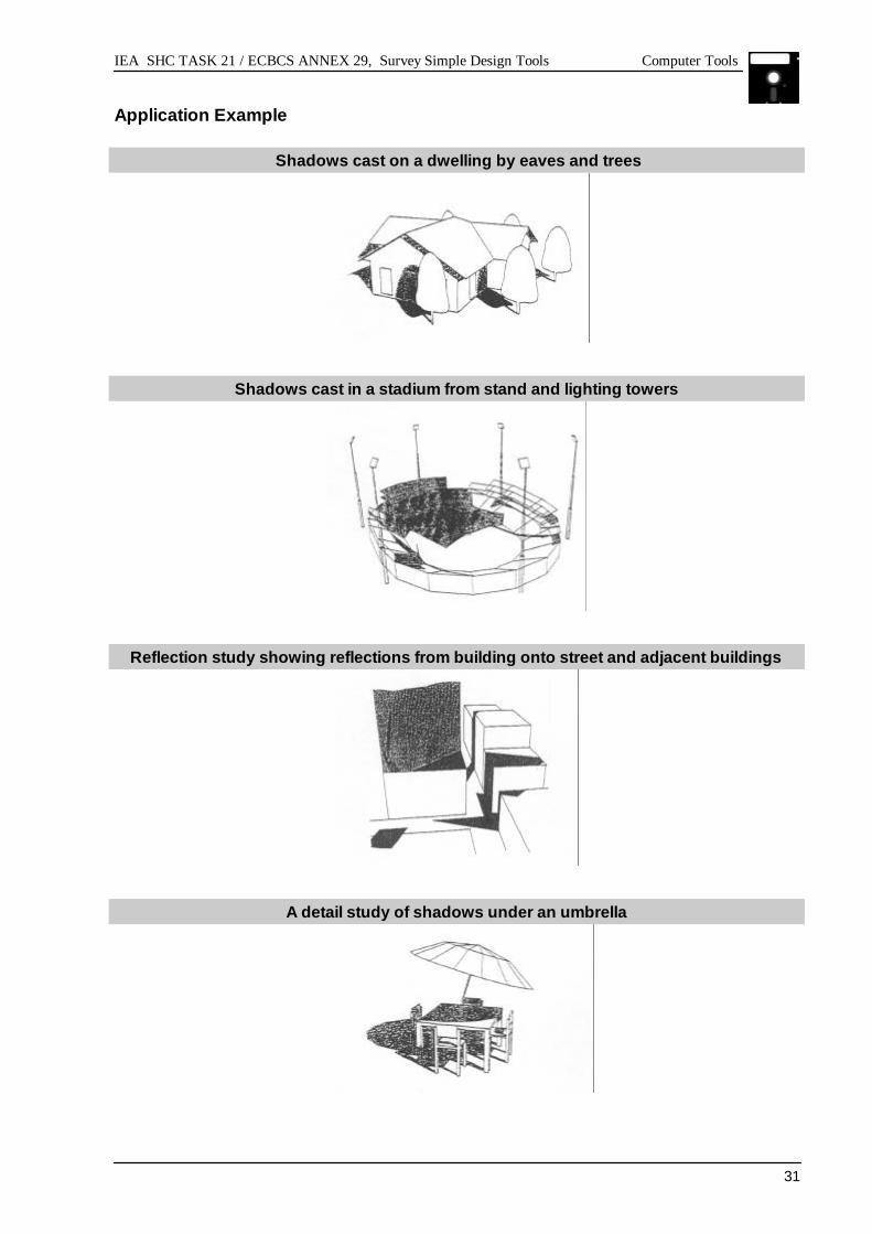
2.6.2 SHADOW AND REFLECTION ANALYSIS
Author / SourceGeoffrey Roy
SubjectShadow and sunlight reflection analysis in the built environment.
DescriptionThe tool may be used for shadow and reflection analysis at all scales, from the study ofshadows cast by an eaves overhang, to shadow and reflection analysis in an urbanprecinct, which might contain many complex buildings. The integrated CAD module isdesigned according to the complexity of problems to be analyzed: allowing for fastmenu driven scene generation, but also encorporating access to a formal commandlanguage for detailed modelling. For calculation of the sun position the programrequires as input the time of day, day of year, geographical latitude and longitude of thesite under investigation. The tool generates graphical output of the scene withsuperimposed shadow and reflection areas. The results from several computations(e.g. different times, dates) can be displayed on the model, either separately orsuperimposed. In this way the path of shadows or reflections during the day (or year)can be easily visualized and therefore analyzed.
DiscussionThe program runs under the operating system MS-DOS. It does not encorporate exactphotometric models, therefore no values, like luminances or illuminances within thescene can be calculated.
References• SR, Shadow and Reflection Analysis, A system for IBM compatible PCs for
modelling the built environment and the computation and display of shadows andreflection caused by sunlight, Geoffrey Roy, Murdoch University, Department ofEngineering, South Street, Murdoch, Western Australia 6150, Australia.
IEA SHC TASK 21 / ECBCS ANNEX 29, Survey Simple Design Tools Computer Tools
31
Application Example
Shadows cast on a dwelling by eaves and trees
Shadows cast in a stadium from stand and lighting towers
Reflection study showing reflections from building onto street and adjacent buildings
A detail study of shadows under an umbrella

IEA SHC TASK 21 / ECBCS ANNEX 29, Survey Simple Design Tools Computer Tools
32
2.6.3 SPREADSHEETS: COLLECTION OF EQUATIONS & DIAGRAMS
Authors / SourceInstitut für Licht- und Bautechnik, KölnFraunhofer Institute for Building Physics, Stuttgart
SubjectMS-EXCEL spreadsheets for basic equations commonly used in daylighting.
DescriptionThe astronomical equations for the calculation of the sun position and definitions of CIEstandard sky models have been transformed into Excel - spreadsheets. As a function oftime and location the sun position, the outside illuminances, luminances at specifiedsky positions etc. can be obtained. Daylight autonomy for a given daylight factor can becalculated. Diverse diagrams are included.
DiscussionWith the widespread use of MS-Excel the tool provides a convenient collection ofspreadsheets for fast access to often required data, especially on the sky models.
References• ILB, Institut für Licht- und Bautechnik an der Fachhochschule Köln, Betzdorferstr. 2,
50679 Köln.• Fraunhofer Institute for Building Physics, Nobelstraße 12, 70569 Stuttgart

IEA SHC TASK 21 / ECBCS ANNEX 29, Survey Simple Design Tools Computer Tools
33
Application Example:
Chart providing the sun position (altitude and azimuth) for a given location at different times ofthe year
Position of the Sun for Cologne
0
10
20
30
40
50
60
70
-180
-170
-160
-150
-140
-130
-120
-110
-100 -90
-80
-70
-60
-50
-40
-30
-20
-10 0 10 20 30 40 50 60 70 80 90 100
110
120
130
140
150
160
170
180
Sun Azimuth
Sun
Alti
tude
EastWest South
5.Ja
4.Feb
21.De
5.Apr
5.Mai
4.Juni
18.No
19.Okt
19.Sep
20.Au
21.Juli
21.Jun
12°
10°°
8°°
6°°
14°°
16°°
18°°
6.März
Chart providing the horizontal external illumin-ance for different sky models at a given location
Horizontal External Illuminance for Stuttgart, 1 st of July
0.00
10000.00
20000.00
30000.00
40000.00
50000.00
60000.00
70000.00
80000.00
90000.00
4 5 6 7 8 9 10 11 12 13 14 15 16 17 18 19 20Time [h]
E[lx
]
Clear Sky Sun + Clear Sky Overcast Sky
Chart for the determination of daylight autonomy. For a given daylight factor the times in a yearare specified, when a certain indoor illuminance is reached
1 3 5 7 9 11 13 15 17 19 21 23 25 27 29 31 33 35 37 39 41 43 45 47 49 51
4.555.566.57.007.508.008.509.009.5010.0010.5011.0011.5012.0012.5013.0013.5014.0014.5015.0015.5016.0016.5017.0017.5018.0018.5019.0019.5020.00
Week in year
Tim
e [h
]
Indoor Illuminance for a daylight factor of 4%
0.0-200.0 200.0-400.0 400.0-600.0 600.0-800.0
200 lx 400 lx
600 lx

IEA SHC TASK 21 / ECBCS ANNEX 29, Survey Simple Design Tools Computer Tools
34
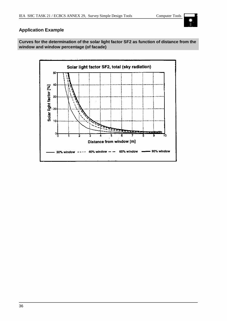
2.6.4 SOLAR LIGHT FACTORS FOR DYNAMIC LIGHTING CONTROL
Authors:Erwin Petersen, Kjeld Johnsen, Karl Grau, Danish Buildding Research Institute
SubjectModel for calculation of illuminance level at reference point based on solar irradianceon windows. The model is integrated in the thermal design tool tsbi3 and can easily beintegrated in other tools. The calculated daylight illuminance level is used as thereference for control of the artificial lighting, hour by hour, or time step by time step,corresponding to the weather data used for simulation.
DescriptionThe daylighting model is based on Solar Light Factors (SF) which describes theilluminance at a spot on a surface in the room divided by the illuminance outside, onthe plane of the glazing of the window. For each window in a room (or group ofwindows) 3 solar light factors are defined, determined for 3 contributions from the solarradiation:the direct solar radiation from the sun: (SF1)diffuse radiation from the sky: (SF2)diffuse, reflected radiation from the ground (and surroundings): (SF3)A fourth solar light factor , SF4, is defined for use of solar shading devices (curtains,venetian blinds etc.). This factor ‘overwrites’ the other factors when the shading isdrawn for the windows, while a mixed case is considered when the shading is onlyused for part of the window(s).
DiscussionCompared to the traditional approach of using the Daylight Factor, the described modelhas the advantage that it can be applied to any type of sky and therefore can also beused in dynamic simulations.As implemented in tsbi3, the model is limited to calculation of the illuminance in onereference point, usually defined on the working plane. Another limitation of the methodis that the three (or four) Solar Light Factors must be determined by other means, e.g.from diagrams or tables. In principle the method can be applied to any roomconfiguration but for calculation of complex rooms, it requires another tool forcalculation of the SFs. The example shows a diagram for the determination of the solarlight factor SF2 with the distance from the window(s) in a 10 m deep room, and fordifferent ‘window-percentages’, i.e. % of the facade.The described approach to daylight prediction at a given reference point of a room hasproven to give reliable results, thus providing the practitioners with an integral toolwhich in one calculation can simulate the thermal, the daylighting, as well as theenergy performance of the buildings.
References

IEA SHC TASK 21 / ECBCS ANNEX 29, Survey Simple Design Tools Computer Tools
35
• tsbi3. Computer program for thermal simulation of buildings. User’s Guide.K. Johnsen and K. Grau, The Danish Building Research Institute, Horsholm,Sept. 1994
IEA SHC TASK 21 / ECBCS ANNEX 29, Survey Simple Design Tools Computer Tools
36
Application Example
Curves for the determination of the solar light factor SF2 as function of distance from thewindow and window percentage (of facade)
IEA SHC TASK 21 / ECBCS ANNEX 29, Survey Simple Design Tools Computer Tools
37
2.6.5 DIAL: QUALITATIVE & QUANTITAVE DAYLIGHTING DESIGN
Authors:Bernard Paule, Jean-Louis Scartezzini, École Polytechnique de Lausanne
SubjectTool for the early design process, based on qualitative information.
DescriptionBeside quantitative estimation of daylight factors and daylight autonomy the toolprovides qualitative diagnosis from expert knowledge translated into fuzzy logic rules.The tool is embedded in an easy to use graphical environment requesting as inputmainly graphical and linguistic information.
DiscussionThe simulation tool requires little -almost none- learning time. No specific knowledgeon daylighting is required, which means that it can be applied quickly in the verydecisive early design phase also by people not deeply involved in lighting technology.The speed of the whole procedure is also particularly well adapted for carrying outparametric studies. So far only rectangular shaped rooms are supported, an extensionto other geometries is intended. The program is adapted to Swiss standards, but it is tobe put on a broader international basis (also including a translation to English).
References• B. Paule, R. Compagnon, J.-L. Scartezzini 1995: Towards a new daylighting design
computer-tool, Proceedings of the Right-Light Three conference, Newcastle uponTyne, England.

IEA SHC TASK 21 / ECBCS ANNEX 29, Survey Simple Design Tools Computer Tools
38
Application Example
Simple interactive graphical specification of input parameters. Example for thespecification of room height and room depth.
The tool allows for a fast calculation of the daylight factor. In addition the daylightautonomy can be displayed.
A genuine feature of the program is the display of qualitative comments on the daylightstudy performed. For the example displayed here, the room depth was way to big.

IEA SHC TASK 21 / ECBCS ANNEX 29, Survey Simple Design Tools Typology
39
2.7.1 TYPOLOGICAL STUDY OF VARIOUS TEST ROOMS
Authors / SourceY. Golay, L. Deschamps, D. Limberis, I. Vogel, J. Dahinden, A. Tschumi.
SubjectTypological study on the influence of main daylighting design parameters.
DescriptionThe tool provides fast accessible graphical as well as numerical information on theinfluence of some main parameters on the illumination and visual appearance of indoorspaces. More than 50 cases have been examined, with modified types, dimensions,positions, and inclines of daylight openings. The provided graphical informationcontains isometric drawings of the rooms, graphs illustrating direct solar penetration forsummer and winter conditions (at solstice), as well as a photorealistic visualisation ofthe test room for an overcast day. The visualization and selected characteristic physicalnumbers (e.g. daylight factor near the window, 3 meters from the window, portion of thesurface area falling below a daylight factor of 2 %) have been simulated using thelighting simulation software RADIANCE. The influence of the various daylight openingson the light distribution in the middle of the room is related to a reference case.Evaluations concerning visual comfort are included.
DiscussionNot only numerical but also visual information is included. This gives a fastunderstanding of the visual perception of daylight in rooms. A powerful simulation toolhas been used to show the strong impact of simple modifications of basic daylightingdesign parameters like window size and placement. The study is not suited forthorough numerical analysis; it should rather be understood as design guide forarchitects and building designers in the early conception of a building. The study hasbeen performed for Swiss conditions, thus some of the provided information is restricedto Swiss latitudes, climates, and regulations.
References• Developed in the LUMEN Program, Grojet CERS 2264.2, Projet NEFF 435.3,
Switzerland, Y. Golay, L. Deschamps, D. Limberis, I. Vogel, J. Dahinden.,A. Tschumi. Edited by EPFL, CH-1015, Lausanne, Switzerland

IEA SHC TASK 21 / ECBCS ANNEX 29, Survey Simple Design Tools Typology
40
Application Example
Exerpt from the typological study showing the impact of different window sizing andpositioning on lighting conditions. Beside graphical information partly obtained fromsimulations performed with the program RADIANCE, basic numerical information isprovided.

IEA SHC TASK 21 / ECBCS ANNEX 29, Survey Simple Design Tools Scale Models1:X
41
2.8.1 ARTIFICIAL SKY / ARTIFICIAL SUN
Authors / SourceDivers, rf. to summary of institutions having testing facilities.
SubjectScale model analyses under artificial skies and suns allows for simple but detailledanalysis of daylight performance.
DescriptionAssuming that the photometric properties of surfaces and transparent daylightopenings are modelled correctly, buildings can be scaled down and be investigatedphotometrically correct under artificial skies and suns. Unlike with thermal, acoustic andstructural models, no scaling corrections for lighting models are required.The design of artificial skies allows to model different sky luminance distributions.Sensors placed within the models monitor illuminance or luminances. Daylight factorscan be obtained by placing a second sensor outside the model.In addition artificial suns allow to perform shadow and reflection analysis by thesimulation of direct sunlight for every time of the year.
DiscussionMany architects work with scale models. Numerous of these models are designed toillustrate the architectural intentions rather than to evaluate lighting design photo-metrically correct. Nevertheless some models are suited for direct use, especially theimpact of direct sunlight under artificial skies can be assessed easily. Artificial skiesand suns allow to perform simple parametric studies quickly. As a limitation it has to bestressed, that detailled models can be very expensive. For changes in the buildingdesign, also the model has to be readjusted. For most practioners it is not economicalto construct own test stands. Therefore a selected list of testing facilities is provided.
References• rf. to list of artificial skies, next page.

IEA SHC TASK 21 / ECBCS ANNEX 29, Survey Simple Design Tools Scale Models1:X
42
Application Example
Example of artificial sky(at Fraunhofer Institut for Building Physics)
Example of artificial sun(at Fraunhofer Institut for Building Physics)
© Thomas Ernsting © Thomas Ernsting
Aritificial skies and suns are (among others) available at these institutes participating inTask 21:
Country Institute Artificial Sky Artificial Sun ContactAustria Bartenbach
LichtlaborYes Yes Lichtplanung Bartenbach
Rinnerstraß e 14,A-6071 Aldranz /Innsbruck
Germany Fraunhofer Institutefor Building Physics
Yes Yes Fraunhofer Institute forBuilding PhysicsDept. of HeatTechnology, Nobelstr.12,D-70569 Stuttgart
Technical UniversityBerlin
Yes TU Berlin, Fakultät fürArchitektur,Straß e des 17. Juni 152,Berlin
Great Britain BRE Yes Yes Building ResearchEstablishment, LightingSection, Bucknalls Lane,UK-Garston, WatfordWD27JR
Netherlands TNO Yes Yes CBO-TNO-TUE Centrefor Building ResearchP.O. Box 513NL-MB Eindhoven
Switzerland EPFL - LESO Yes Yes LESO-PB / EPFL, CH-1015, Lausanne
U.S.A LBNL Yes Yes Lawrence BerkeleyLaboratory, Window andDaylighting Group,Berkeley, CA 94720

IEA SHC TASK 21 / ECBCS ANNEX 29, Survey Simple Design Tools Characterization
43
3 CHARACTERIZATION OF THE REVIEWED TOOLS
The tabular overview on the next page, characterising the tools according to a set ofusage related attributes, allows for a problem-sensitive selection of tools:
General The table first of all gives a general judgement of the Flexibility in theapplication of the tools. The Application of some tools is restricted toLocal climates or specific national regulation, others can be usedanywhere. Some tools like the Horizontoscope are globally applicable,nevertheless require for instance projection charts dependent on thelatitude. In such cases the Global as well as Local attributes arechecked.
Input The input required by the diverse methods has been characterisedacoording to Sky, Geometric Space and Windows type treatable.
Output The classification of tool output is subdivided into the basic Methodemployed (weather it is Single Stage method, therefore the tooldelivers the desired output directly or weather for instant for obtainingthe daylight factor multiple steps as there are the Direct Componentand the Interreflected Component have to be calculated) and the Typeof output to be obtained.
Software It is checked weather the reviewed tools are available or can betransformed into Spreadsheets with reasonable effort. Computer toolsare classified according to Operating System and the GraphicalInterface.

IEA SHC TASK 21 / ECBCS ANNEX 29, Survey Simple Design Tools Characterization
44

IEA SHC TASK 21 / ECBCS ANNEX 29, Survey Simple Design Tools List of Contact Persons
45
4 LIST OF CONTACT PERSONS
Task 21 & Annex 29 Operating Agent:
Kjeld JohnsonStatens ByggeforskingsinstitutDr. Neergards Vej 15DK - 2970 HorsholmPhone: +45-45-865533Fax: +45-45867535
Leader Subtask A:Nancy RuckUniversity of SydneyDept. of Architecture & Design ScienceSydney NSW 2006, AUSTRALIAPhone: +61 2 9351 4029Fax: +61 2 9351 3031
Leader Subtask B:Laurens ZonnefeldtCBO-TNO-TUECentre for Building ResearchP.O.Box 513NL - MB EindhovenPhone: +31 40 247 2814Fax: +31-40 243 8595
Leader Subtask C:Hans ErhornFraunhofer-Institut für BauphysikNobelstraß e 12D-70569 StuttgartPhone: +49 711 9703380Fax: +49 711 9703399
Leader Subtask D:Poul Erik KristensenDanisch Technological InstituteDivision of EnergyP.O. Box 141DK-2630 TaastPhone: +45 4350 4560Fax: +45 4350 7222

IEA SHC TASK 21 / ECBCS ANNEX 29, Survey Simple Design Tools List of Contact Persons
46
Members of Subtask C:
Australia:Geoffrey RoyMurdoch UniversitySchool of EngineeringMurdoch, WA. 6150Phone: +61 9 360 2163Fax: +61 9 360 2941
Belgium:Magali BodartUniversité Catholique de LouvainArchitecture et Climat1, Place du Levant1348 Louvain-la-NeuvePhone: +32 1047 22 23Fax: +32 1047 2150
Canada:Morad AtifNational Research Council CanadaBuilding Performance LaboratoryOttawa, Ontario, K1A 0R6Phone: +1 613 993 9629Fax: +1-613-954-3733
Denmark:Karl GrauDanish Building Research InstituteDr. Neergards Vej 152970 HorsholmPhone: +45-45-865533Fax: +45-45867535
France:Marc FontoynontENTPE/DGCBRue Maurice Audin69518 Vaulx-en-Velin, CedexPhone: +33-7204-7035Fax: +33-7204-7041

IEA SHC TASK 21 / ECBCS ANNEX 29, Survey Simple Design Tools List of Contact Persons
47
Pierre LaforgueENTPE/DGCBRue Maurice Audin69518 Vaulx-en-Velin,CedexPhone: +33-7204 7006Fax: +33-7204 7041
Germany:Jan de BoerFraunhofer-Institut für BauphysikNobelstraß e 1270569 StuttgartPhone: +49 711 9703401Fax: +49 711 9703399
Michael DirksmöllerFraunhofer-Institut für BauphysikNobelstraß e 1270569 StuttgartPhone: +49 711 9703327Fax: +49 711 9703399
Martin Kischkoweit-LopinFH KölnInstitut für Licht- und BautechnikGremberger Straß e 151a51505 KölnPhone: +49 221 831096Fax: +49 221 835513
Sweden:Nils SvendeniusUniversity of LundPhysics DepartmentSölvegatan 14223 62 LundPhone: +46 46 222 7736Fax: +46 46 222-4709
Switzerland:Nicole HopkirkEMPA DübendorfÜ berlandstr. 1298600 DübendorfPhone: +41 1 823 4791Fax: +41-1-821 6244

IEA SHC TASK 21 / ECBCS ANNEX 29, Survey Simple Design Tools List of Contact Persons
48
Bernard PauleLESO-PB/EPFLCH - 1015 LausannePhone: +41216935554Fax: +41-21 693 5550
Jean-Louis ScartezziniLESO-PB/EPFLCH - 1015 LausannePhone: +41 21 693 4545Fax: +41-21 693 2722
United Kingdom:Maurice AizlewoodBuilding Research EstablishmentLighting SectionBucknalls LaneUK-Garston, Watford WD2 7JRPhone: +44 1923 664 871Fax: +44-1923 664 095
United States:Bill CarrollLawrence Berkeley LaboratoryBldg. 90 - 3026Berkeley, CA 94720, USAPhone: +1 510 486 4890Fax: +1-510 486 5454