Hardware Maintenance Manual: xSeries 300 - ps...
120
Hardware Maintenance Manual xSeries 300
Transcript of Hardware Maintenance Manual: xSeries 300 - ps...

Hardware Maintenance Manual
xSeries 300
���


Hardware Maintenance Manual
xSeries 300
���

NoteBefore using this information and the product it supports, be sure to read the general information under “Notices” onpage 109.
First Edition (May 2001) (Updated February 2002)
The following paragraph does not apply to the United Kingdom or any country where such provisions areinconsistent with local law.
INTERNATIONAL BUSINESS MACHINES CORPORATION PROVIDES THIS PUBLICATION ″AS IS″ WITHOUTWARRANTY OF ANY KIND, EITHER EXPRESS OR IMPLIED, INCLUDING, BUT NOT LIMITED TO, THEIMPLIED WARRANTIES OF MERCHANTABILITY OR FITNESS FOR A PARTICULAR PURPOSE. Some states donot allow disclaimer of express or implied warranties in certain transactions, therefore, this statement may notapply to you.
This publication could include technical inaccuracies or typographical errors. Changes are periodically made to theinformation herein; these changes will be incorporated in new editions of the publication. IBM may makeimprovements and/or changes in the product(s) and/or the program(s) described in this publication at any time.
This publication was developed for products and services offered in the United States of America. IBM may notoffer the products, services, or features discussed in this document in other countries, and the information is subjectto change without notice.Consult your local IBM representative for information on the products, services, and features available in your area.
Requests for technical information about IBM products should be made to your IBM reseller or IBM marketingrepresentative.
© Copyright International Business Machines Corporation 2000. All rights reserved.US Government Users Restricted Rights – Use, duplication or disclosure restricted by GSA ADP Schedule Contractwith IBM Corp.
About this manual
This manual contains diagnostic information, a Symptom-to-FRU index, serviceinformation, error codes, error messages, and configuration information for the
IBM®
xSeries 300 server.
Important: This manual is intended for trained servicers who are familiar withIBM PC Server products.
Important safety informationBe sure to read all caution and danger statements in this book before performingany of the instructions.
Leia todas as instruções de cuidado e perigo antes de executar qualquer operação.
Prenez connaissance de toutes les consignes de type Attention et
Danger avant de procéder aux opérations décrites par les instructions.
© Copyright IBM Corp. 2000 iii

Lesen Sie alle Sicherheitshinweise, bevor Sie eine Anweisung ausführen.
Accertarsi di leggere tutti gli avvisi di attenzione e di pericolo prima di effettuarequalsiasi operazione.
Lea atentamente todas las declaraciones de precaución y peligro ante de llevar acabo cualquier operación.
Online SupportUse the World Wide Web (WWW) to download Diagnostic, BIOS Flash, and DeviceDriver files.
File download address is:
http://www.us.pc.ibm.com/files.html
IBM Online AddressesThe HMM manuals online address is:
http://www.us.pc.ibm.com/cdt/hmm.html
The IBM PC Company Support Page is:
http://www.us.pc.ibm.com/support/index.html
The IBM PC Company Home Page is:
http://www.pc.ibm.com
iv Hardware Maintenance Manual: xSeries 300

Contents
About this manual . . . . . . . . . . iiiImportant safety information . . . . . . . . iiiOnline Support . . . . . . . . . . . . . iv
IBM Online Addresses . . . . . . . . . . iv
Chapter 1. General checkout . . . . . . 1
Chapter 2. General information . . . . . 3Features and specifications. . . . . . . . . . 4What the IBM xSeries 300 offers . . . . . . . . 5Reliability, availability, and serviceability features . . 6Server controls and indicators . . . . . . . . 7
Front view . . . . . . . . . . . . . . 7Rear view . . . . . . . . . . . . . . 8Turning on the server . . . . . . . . . . 9Turning off the server . . . . . . . . . . 9Standby mode . . . . . . . . . . . . 10
Chapter 3. Diagnostics . . . . . . . . 11Diagnostic tools overview . . . . . . . . . 11POST . . . . . . . . . . . . . . . . 11
POST beep code descriptions . . . . . . . 11POST error messages . . . . . . . . . . 11
Small computer system interface messages (somemodels). . . . . . . . . . . . . . . . 12Diagnostic programs and error messages . . . . 12
Text messages . . . . . . . . . . . . 13Starting the diagnostic programs . . . . . . 14
Using the diagnostics CD. . . . . . . . 14Downloading the diagnostics program . . . 14Using the diagnostic diskette . . . . . . 15
Viewing the test log . . . . . . . . . . 15Diagnostic error message tables. . . . . . . 15
Power checkout . . . . . . . . . . . . . 16Recovering BIOS code . . . . . . . . . . . 17Clearing CMOS . . . . . . . . . . . . . 19Replacing the battery . . . . . . . . . . . 19Temperature checkout . . . . . . . . . . . 21Diagnosing errors . . . . . . . . . . . . 21Troubleshooting the Ethernet controller . . . . . 22
Network connection problems . . . . . . . 22Ethernet controller troubleshooting chart . . . 22
Ethernet controller messages. . . . . . . . . 24Novell NetWare or IntraNetWare system ODIdriver teaming messages . . . . . . . . . 24NDIS 4.0 (Windows NT) driver messages . . . 25Ethernet teaming messages: . . . . . . . . 27
Chapter 4. Configuring the server . . . 29Starting the utility programs. . . . . . . . . 30
Using the Configuration/Setup Utility program 30Starting the Configuration/Setup Utilityprogram . . . . . . . . . . . . . 30
Using the SCSISelect utility program (somemodels). . . . . . . . . . . . . . . 30
Starting the SCSISelect utility program . . . 30Using the PXE boot agent utility program . . . 31
Starting the PXE boot agent utility program 31Using the ServerGuide CDs . . . . . . . . 32ServerGuide startup problems . . . . . . . 33
Chapter 5. Installing Options . . . . . 35Major components of the xSeries 300 server . . . 36Before you begin . . . . . . . . . . . . 36
Working inside the server with the power on . . 37System reliability considerations . . . . . . 37Handling static-sensitive devices . . . . . . 37
Removing the cover . . . . . . . . . . . 38System board . . . . . . . . . . . . . . 39System board internal cable connectors . . . . . 40System board jumpers . . . . . . . . . . . 41Working with adapters . . . . . . . . . . 41
Adapter considerations . . . . . . . . . 42Installing an adapter . . . . . . . . . . 42
Hard disk drives . . . . . . . . . . . . 44Installing or replacing a hard disk drive . . . . 44
Working with DIMMs . . . . . . . . . . . 45Installing DIMMs . . . . . . . . . . . 45
Replacing the fan assembly . . . . . . . . . 47Removing and installing a microprocessor . . . . 47
Removing a microprocessor . . . . . . . . 49Installing a microprocessor . . . . . . . . 51
Installing the cover . . . . . . . . . . . . 53Working with cables . . . . . . . . . . . 54
Chapter 6. FRU information (serviceonly). . . . . . . . . . . . . . . . 55Diskette/CD-ROM drives. . . . . . . . . . 55Diskette/CD-ROM drive bracket . . . . . . . 56Power supply - AC . . . . . . . . . . . . 57Power supply - DC . . . . . . . . . . . . 57
Before you begin . . . . . . . . . . . 57Wiring the – 48 V dc power connection to thepower supply . . . . . . . . . . . . 57
Single input instructions . . . . . . . . 58Dual input instructions . . . . . . . . 60
Disconnecting the DC Power Connection . . . . 60PCI riser card. . . . . . . . . . . . . . 61System board . . . . . . . . . . . . . . 62
Chapter 7. Symptom-to-FRU index . . . 63Beep symptoms . . . . . . . . . . . . . 63No beep symptoms. . . . . . . . . . . . 63Diagnostic error codes . . . . . . . . . . . 63Error symptoms . . . . . . . . . . . . . 66POST error codes . . . . . . . . . . . . 69ServeRAID . . . . . . . . . . . . . . 70Undetermined problems . . . . . . . . . . 70
© Copyright IBM Corp. 2000 v

Chapter 8. Parts listing . . . . . . . . 71Keyboards . . . . . . . . . . . . . . . 72
Power cords . . . . . . . . . . . . . 73
Chapter 9. Related service information 75Safety information . . . . . . . . . . . . 75
General safety . . . . . . . . . . . . 75Electrical safety . . . . . . . . . . . . 76
Safety inspection guide . . . . . . . . . 77Handling electrostatic discharge-sensitive devices 78Grounding requirements . . . . . . . . . 79Safety notices (multi-lingual translations) . . . 79
Send us your comments! . . . . . . . . . 108Problem determination tips. . . . . . . . . 109Notices . . . . . . . . . . . . . . . 109Trademarks . . . . . . . . . . . . . . 110
vi Hardware Maintenance Manual: xSeries 300

Chapter 1. General checkout
The server diagnostic programs are stored on CD-ROM. These programs are theprimary method of testing the major components of the server: the system board,Ethernet controller, video controller, RAM, keyboard, mouse (pointing device),diskette drive, serial ports, and hard drives. You can also use them to test someexternal devices. See “Diagnostic programs and error messages” on page 12.
Also, if you cannot determine whether a problem is caused by the hardware or bythe software, you can run the diagnostic programs to confirm that the hardware isworking properly.
When you run the diagnostic programs, a single problem might cause several errormessages. When this occurs, work to correct the cause of the first error message.After the cause of the first error message is corrected, the other error messagesmight not occur the next time you run the test.
A failed system might be part of a shared DASD cluster (two or more systemssharing the same external storage device(s)). Prior to running diagnostics, verifythat the failing system is not part of a shared DASD cluster.
A system might be part of a cluster if:v The customer identifies the system as part of a cluster.v One or more external storage units are attached to the system and at least one of
the attached storage units is additionally attached to another system orunidentifiable source.
v One or more systems are located near the failing system.
If the failing system is suspected to be part of a shared DASD cluster, alldiagnostic tests can be run except diagnostic tests which test the storage unit(DASD residing in the storage unit) or the storage adapter attached to the storageunit.
Notes:
1. Safety information, see “Safety information” on page 75.2. For systems that are part of a shared DASD cluster, run one test at a time in
looped mode. Do not run all tests in looped mode, as this could enable theDASD diagnostic tests.
3. If multiple error codes are displayed, diagnose the first error code displayed.4. If the computer hangs with a POST error, go to “POST error codes” on page 69.
© Copyright IBM Corp. 2000 1

2 Hardware Maintenance Manual: xSeries 300
Chapter 2. General information
The IBM®
xSeries 300 server is a one U-high1 rack-model server forhigh-volume network transaction processing. This high-performance server isideally suited for networking environments that require superior microprocessorperformance, efficient memory management, flexibility, and reliable data storage.
The xSeries 300 server comes with a three-year limited warranty and IBM ServerStart Up Support. If you have access to the World Wide Web, you can obtainup-to-date information about your xSeries 300 model and other IBM serverproducts at the following World Wide Web addresses:
http://www.ibm.com/eserver/xseries
http://www.ibm.com/
1. Racks are marked in vertical increments of 1.75 inches each. Each increment is referred to as a unit, or a ″U″. A one-U-high deviceis 1.75 inches tall.
© Copyright IBM Corp. 2000 3

Features and specificationsThe following table provides a summary of the features and specifications for yourxSeries 300.
Microprocessor:
Supports either of the two listedmicroprocessors (depending on yourmodel)v One Intel® Pentium®® III with 256
KB* Level-2 cache and MMX™™
(MMX2) technology
orv One Intel Celeron™ with 128 KB
Level-2 cache and MMX (MMX2)technology
Memory:v Minimum: 128 MB*v Maximum: 1.5 GB*v Type: PC133 MHz, ECC SDRAM,
unregistered DIMMs onlyv Slots: Three dual inlinev Supports 128, 256, and 512 MB
DIMMs
Drives:v Diskette: 1.44 MBv CD-ROM: 24X IDEv Supports up to two hard disk
drives
Expansion bays:
Two 3.5-in. slim-high bays for harddisk drives
PCI expansion slots:
Two 33 MHz/32-bit on the systemboard
Power supply:
200 watt (110 or 220 V acauto-sensing) with Wake on LANsupport
Video:v S3 Savage 4 Pro video on system
boardv Compatible with SVGA and VGAv 8 MB SDRAM video memory
Size:
v Height: 4.37 cm (1.75 inches, 1U)
v Depth: 63.5 cm (25 inches)
v Width: 44 cm (17.32 inches)
v Maximum weight: 19.05 kg (42 lb)depending on your configuration
Integrated functions:v Dual 10BASE-T/100BASE-TX
Ethernet controllers on the systemboard with Alert on LAN
™2
supportv Serial portv Two USB portsv Keyboard portv Mouse portv Dual-channel bus mastering IDE
controller
Hard disk controller:
v All models-Dual-channel busmastering IDE controller
v Some models-SCSI adapter(Adaptec Ultra160) is installed inone of the expansion-slots
Acoustical noise emissions:
v Sound power, idling: 6.6 belmaximum
v Sound power, operating: 6.8 belmaximum
Environment:v Air temperature:
– Server on: 10° to 35° C (50.0° to95.0° F). Altitude: 0 to 914 m(2998.7 ft)
– Server on: 10° to 32° C (50.0° to89.6° F). Altitude: 914 m (2998.7ft) to 2133 m (6998.0 ft.)
– Server off: -40° to 60° C(-104° to 140° F). Maximumaltitude: 2133 m (6998.0 ft)
v Humidity:– Server on: 8% to 80%– Server off: 5% to 100%
Heat output:
Approximate heat output in Britishthermal unit (Btu) per hourv Minimum configuration: 171 Btu (50
watts)v Maximum configuration: 410 Btu
(120 watts)
Electrical input:v Sine-wave input (47-63 Hz) requiredv Input voltage low range:
– Minimum: 90 V ac– Maximum: 137 V ac
v Input voltage high range:– Minimum: 180 V ac– Maximum: 265 V ac
v Input kilovolt-amperes (kVA)approximately:– Minimum: 0.095 kVA– Maximum: 0.213 kVA
*KB equals approximately 1000 bytes. MB equals approximately 1000000 bytes. GBequals approximately 1000000000 bytes.
4 Hardware Maintenance Manual: xSeries 300

What the IBM xSeries 300 offersThe design of your server takes advantage of advancements in memorymanagement and data storage. Your server includes:v Impressive performance using the latest microprocessor technology.
Your server comes with one Intel Celeron or one Pentium III microprocessorinstalled.
v Large system memoryThe memory bus in your server supports up to 1.5 GB of system memory. Thememory controller provides error code correction (ECC) support for up to threeindustry-standard PC133, 3.3 V, 168-pin, 133 megahertz (MHz), unregistered,synchronous dynamic random access memory (SDRAM) dual inline memorymodules (DIMMs).
v Systems-management capabilitiesSee the documentation provided with your systems-management software formore information.
v Integrated network environment supportYour server comes with two Intel Ethernet controllers on the system board.These Ethernet controllers have an interface for connecting to 10-Mbps or100-Mbps networks. The server automatically selects between 10BASE-T and100BASE-TX environments. The controller provides full-duplex (FDX) capability,which enables simultaneous transmission and reception of data on the Ethernetlocal area network (LAN). These controllers support Alert on LAN 2 technology.
v IBM® ServerGuide™™ CDsThe ServerGuide CDs that are included with your server provide programs tohelp you set up your server and install the network operating system (NOS).The ServerGuide program detects the hardware options that are installed andprovides the correct configuration programs and device drivers. In addition, theServerGuide CDs include a variety of application programs for your server.
Chapter 2. General information 5

Reliability, availability, and serviceability featuresThree of the most important features in server design are reliability, availability,and serviceability (RAS). These RAS features help to ensure the integrity of thedata stored on your server; that your server is available when you want to use it;and that should a failure occur, you can easily diagnose and repair the failure withminimal inconvenience.
The following is an abbreviated list of the RAS features that your server supports.v Reliability features
– Boot block recovery– Cooling fans with speed-sensing capability– Customer-upgradable basic input and output system (BIOS) code– ECC front-side buses (FSBs) and L2 cache– Advanced configuration and power interface (ACPI)– Power-on self-test (POST)– SDRAM with serial presence detect (SPD)
v Availability features– Advanced desktop management interface (DMI) features– Auto-restart initial program load (IPL) power supply– Automatic error retry or recovery– Automatic server restart– Automatic restart after power failure– Built-in, menu-driven configuration programs– Built-in, menu-driven setup programs– Failover Ethernet support– Menu-driven diagnostic programs on CD-ROM– Microsoft® Windows NT® failover support– Monitoring support for temperature, voltage, and fan speed– Server management– Wake on LAN® capability
v Serviceability features– 24 hours per day, seven days a week customer support2
– Adaptec 29160LP built-in self-test (BIST)– Alert on LAN 2™
– CD-ROM-based diagnostics– Diagnostic support of Ethernet controllers– Error codes and messages– Processor serial number access– Read-only memory (ROM) checksums– Standard cables present detection– Standby voltage for system management features and monitoring– System error logging– Vital product data (VPD) (includes information stored in nonvolatile memory
for easier remote viewing)
2. Service availability will vary by country. Response time will vary depending on the number and nature of incoming calls.
6 Hardware Maintenance Manual: xSeries 300

Server controls and indicatorsThe following section identifies the controls and indicators on the front and rear ofyour server.
Front viewPower controlbutton
Power-onlight (green)
Resetbutton
System errorlight (amber)
Diskette driveactivity light(green)
Diskette ejectbutton
CD eject buttonCD activitylight (green)
Power-control button: Press this button to manually turn the server on or off.
Power-on light: This green LED lights and stays on when you turn on your server,and it blinks when the server is in standby mode.
Reset button: Press this button to reset the server and run the power-on self-test(POST). You might need to use a pen or the end of a straightened paper clip topress the button.
System-error light: This amber LED lights when a system error occurs.
Diskette drive activity light: When this LED is on, it indicates that the diskettedrive is in use.
Diskette-eject button: Push this button to release a diskette from the drive.
CD eject button: Push this button to release a CD from the drive.
CD drive activity light: When this light is on, it indicates that the CD-ROM driveis in use.
Chapter 2. General information 7

Rear view
Ethernet 1 speedindicator (green)
Ethernet 2 speedindicator (green)
Ethernet 1 linkindicator (amber)
Ethernet 2 linkindicator (amber)
Power-on light (green)
System errorlight (amber)
Serial port
USB 1
USB 2 Video port
Mouse or auxilarypointing device connector
Keyboard portSystem powerconnector
System power connector: The system power cord connects here to provide powerto the system.
Ethernet 1 link indicator: This amber LED lights when there is an active linkconnection on the 10BASE-T or 100BASE-TX interface for Ethernet port 1.
Ethernet 1 speed indicator: This green LED lights when the speed of the EthernetLAN that is connected to Ethernet port 1 is 100 Mbps.
Auxiliary pointing device: Signal cables for a mouse, trackball, or other pointingdevice connect to the Auxiliary pointing device connector.
Keyboard port: Signal cables for a keyboard connect to the keyboard port.
Power-on light: This green LED lights and stays on when you turn on your serverand will blink when the server is in standby mode. This light duplicates the poweron light on the front of the server.
Video port: The signal cable for a monitor connects to the video port.
Serial port: Signal cables for modems or other serial devices connect to the serialport.
USB 2: This is an automatically configured port that you can use to connect one ormore USB devices to the server, using Plug and Play technology.
USB 1: This is an automatically configured port that you can use to connect one ormore USB devices to the server, using Plug and Play technology.
System-error light: This amber LED lights when a system error occurs. This lightduplicates the system error light on the front of the server.
Ethernet 2 speed indicator: This green LED lights when the speed of the EthernetLAN connected to Ethernet port 2 is 100 Mbps.
Ethernet 2 link indicator: This amber LED lights when there is an active linkconnection on the 10BASE-T or 100BASE-TX interface for Ethernet port 2.
8 Hardware Maintenance Manual: xSeries 300

Turning on the serverTurning on the server refers to the act of plugging the power cord of your serverinto the power source and starting the operating system.
Complete the following steps to turn on the server:1. Plug the power cord of your server into the power source.
Note: Plugging the power cord into a power source may cause the server tostart automatically. This is an acceptable action.
2. Wait 30 seconds, and then press the power control button on the front of theserver.
Turning off the serverTurning off the server refers to the act of disconnecting the server from the powersource.
Complete the following steps to turn off the server:1. Refer to your operating system documentation for the proper procedure to shut
down the operating system.Statement 5:
CAUTION:
The power control button on the device and the power switch on the powersupply do not turn off the electrical current supplied to the device. Thedevice also might have more than one power cord. To remove all electricalcurrent from the device, ensure that all power cords are disconnected fromthe power source.
1
2
2. Press the power control button on the front of the server. This will put theserver in standby mode.
3. Disconnect the server from the power source.
Note: After you turn off the server, wait at least 5 seconds before you turn onthe server again.
Chapter 2. General information 9

Standby modeStandby mode puts the server into a wait state. When in a wait state, the server isnot running the operating system, and all core logic is shut down.
Complete the following steps to put the server into the standby mode:1. Refer to your operating system documentation for the proper procedure to
shutdown the operating system.2. Press the power control button on the front of the server.
10 Hardware Maintenance Manual: xSeries 300
Chapter 3. Diagnostics
This section provides basic troubleshooting information to help you resolve somecommon problems that might occur with the server.
If you cannot locate and correct the problem using the information in this section,refer to Chapter 7, “Symptom-to-FRU index” on page 63 for more information.
Diagnostic tools overviewThe following tools are available to help you identify and resolve hardware-relatedproblems:v POST beep codes
The power-on self-test (POST) generates beep codes and messages to indicatesuccessful test completion or the detection of a problem. See “POST” for moreinformation.
v Diagnostic programs and error messages
The server diagnostic programs are provided on the IBM Enhanced DiagnosticsCD. These programs test the major components of the server. See “Diagnosticprograms and error messages” on page 12 for more information.
POSTWhen you turn on the server, it performs a series of tests to check the operation ofserver components and some of the options installed in the server. This series oftests is called the power-on self-test or POST.
If POST finishes without detecting any problems, the first window of the operatingsystem or application program appears.
Note:
1. If you have a power-on password or administrator password set, youmust type the password and press Enter, when prompted, before POSTwill continue.
2. A single problem might cause several error messages. When this occurs,work to correct the cause of the first error message. After you correct thecause of the first error message, the other error messages usually will notoccur the next time you run the test.
POST beep code descriptionsPOST generates beep codes to indicate successful completion or the detection of aproblem.v One short beep indicates the successful completion of POST.v More than one beep indicates that POST detected a problem. For more
information, see “Beep symptoms” on page 63“.
POST error messagesThe possible types of beep codes that your system might emit are:
© Copyright IBM Corp. 2000 11

Repeating long beepsIndicates that a memory error has occurred. Ensure that all DIMMs arecorrectly installed.
One long beep and two short beepsIndicates that a video error has occurred and the BIOS cannot initialize thevideo screen to display any additional information. Ensure that the videoadapter is correctly installed.
For a list of POST errors, see “POST error codes” on page 69.
Small computer system interface messages (some models)The following table lists actions to take if you receive a SCSI error message.
Note: If the server does not have a hard disk drive, ignore any message thatindicates that the BIOS is not installed.
You will get these messages only when running the SCSI Select Utility.
Table 1. SCSI messages
SCSI Messages Description
All One or more of the following might be causing the problem.
v A failing SCSI device (adapter or drive)
v An improper SCSI configuration
v Duplicate SCSI IDs in the same SCSI chain
v An improperly installed SCSI terminator
v A defective SCSI terminator
v An improperly installed cable
v A defective cable
Action: Verify that:
v The external SCSI devices are turned on. External SCSI devices mustbe turned on before the server.
v The cables for all external SCSI devices are connected correctly.
v The last device in each SCSI chain is terminated properly.
v The SCSI devices are configured correctly.
If the above items are correct, run the diagnostic programs to obtainadditional information about the failing device.
Diagnostic programs and error messagesThe server diagnostic programs are stored on the IBM Enhanced Diagnostics CD.These programs provide the primary methods of testing the major components ofthe server.
Diagnostic error messages indicate that a problem exists; they are not intended tobe used to identify a failing part. Troubleshooting and servicing of complexproblems that are indicated by error messages should be performed by trainedservice personnel.
12 Hardware Maintenance Manual: xSeries 300

Sometimes the first error to occur causes additional errors. In this case, the serverdisplays more than one error message. Always follow the suggested actioninstructions for the first error message that appears.
The following sections contain the error codes that might appear in the detailedtest log and summary log when running the diagnostic programs.
The error code format is as follows:fff-ttt-iii-date-cc-text message
where:
fff is the three-digit function code that indicates the function beingtested when the error occurred. For example, function code 089 isfor the microprocessor.
ttt is the three-digit failure code that indicates the exact test failurethat was encountered.
iii is the three-digit device ID.
date is the date that the diagnostic test was run and the error recorded.
cc is the check digit that is used to verify the validity of theinformation.
text message is the diagnostic message that indicates the reason for the problem.
Text messagesThe diagnostic text message format is as follows:Function Name: Result (test specific string)
where:
Function Nameis the name of the function being tested when the error occurred. Thiscorresponds to the function code (fff) given in the previous list.
Result can be one of the following:
PassedThis result occurs when the diagnostic test completes without anyerrors.
Failed This result occurs when the diagnostic test discovers an error.
User AbortedThis result occurs when you stop the diagnostic test before it iscomplete.
Not ApplicableThis result occurs when you specify a diagnostic test for a devicethat is not present.
AbortedThis result occurs when the test could not proceed because of theserver configuration.
WarningThis result occurs when a possible problem is reported during thediagnostic test, such as when a device that is to be tested is notinstalled.
Chapter 3. Diagnostics 13

Test Specific StringThis is additional information that is used to analyze the problem.
Starting the diagnostic programsThe IBM Enhanced Diagnostics programs will isolate your server hardware fromsoftware that you have installed on your hard disk drive. The programs runindependently of the operating system, and must be run either from the CD ordiskette. This method of testing is generally used when other methods are notaccessible or have not been successful in isolating a problem suspected to behardware related.
An IBM Enhanced Diagnostics CD comes with the server. You can also downloadthe latest image of the diagnostics from the World Wide Web athttp://www.ibm.com/pc/support.
Note: When using diagnostics with a USB Keyboard and Mouse attached, go intoSetup and enable USB emulation.1. Press F1 Config/Setup2. Select Devices and I/O Ports3. Select USB Setup4. Make sure USB Keyboard and Mouse are enabled.
Using the diagnostics CDTo start the IBM Enhanced Diagnostics using the CD, do the following:1. Turn off your server and any peripheral devices.2. Turn on all attached devices; then, turn your server on.3. When you see Press F1 For Configuration/Setup, press the F1 key.4. When the Configuration/Setup Utility menu appears, select Start Options.5. From the Start Options menu, select Startup Sequence.6. Note the device selected as the First Startup Device. Later, you must restore
this setting.7. Select CD-ROM as the First Startup Device.8. Press Esc two times to return to the Configuration/Setup Utility menu.9. Place the IBM Enhanced Diagnostics CD in the CD-ROM drive.
10. Select Save & Exit Setup and follow the prompts. The diagnostics will load.Follow the instructions on the screen to run the diagnostics.
Important
When you finish running the diagnostics and utilities, remove the CD from the CD-ROMdrive and turn off the server. You must restore the First Startup Device to the originalsetting. Use steps 2 through 8 of this procedure to do this.
Downloading the diagnostics programDo the following to download the latest image of the IBM Enhanced Diagnosticsfrom the World Wide Web and create a startable Enhanced Diagnostics diskette:1. Go to the following World Wide Web site: http://www.ibm.com/pc/support/2. Download the diagnostics file for your server to a hard disk drive directory
(not to a diskette).3. Go to a DOS prompt and change to the directory where the file was
downloaded.
14 Hardware Maintenance Manual: xSeries 300

4. Insert a blank high-density diskette in diskette drive A.5. Type in the following, and then press Enter: filename a: where filename is the
name of the file you downloaded from the Web.
The downloaded file is self-extracting and will be copied to the diskette. When thecopy completes, you have a startable IBM Enhanced Diagnostics diskette.
Using the diagnostic disketteDo the following to start the IBM Enhanced Diagnostics using the diagnosticsdiskette, do the following:1. Turn off your server and any peripheral devices.2. Insert the IBM Enhanced Diagnostics diskette into the diskette drive.3. Turn on all attached devices; then, turn on the server.4. Follow the instructions on the screen.5. Place the IBM Enhanced Diagnostics CD in the CD-ROM drive. The diagnostics
will load. Follow the instructions on the screen to run the diagnostics.
When the tests have completed, you can view the Test Log by selecting Utilityfrom the top of the screen.
If the hardware checks out OK but the problem persists during normal serveroperations, a software error might be the cause. If you suspect a software problem,refer to the information that comes with the software package.
Viewing the test logThe test log records data about system failures and other pertinent information.The test log will not contain any information until after the diagnostic program hasrun.
Note: If you already are running the diagnostic programs, begin with step 41. Insert the IBM Enhanced Diagnostics CD.2. Turn on the system and watch the screen.
If the system is on, shut down your operating system and restart the system.3. If a power-on password is set, the system prompts you for it. Type in the
appropriate password; then, press Enter.4. Run the appropriate diagnostics program and when the Diagnostic Programs
screen appears, select Utility.5. Select View Test Log from the list that appears; then, follow the instructions on
the screen.6. You can save the test log to a file on a diskette or to your hard disk drive.
Note: The system maintains the test-log data while the system is powered on.When you turn off the power to the server, the test log is cleared.
Diagnostic error message tablesFor descriptions of the error messages that might appear when you run thediagnostic programs, see “Diagnostic error codes” on page 63. If diagnostic errormessages appear that are not listed in those tables, make sure that the server hasthe latest levels of BIOS, Advanced System Management Processor, ServeRAID,and diagnostics microcode installed.
Chapter 3. Diagnostics 15

Power checkoutPower problems can be difficult to troubleshoot. For instance, a short circuit canexist anywhere on any of the power distribution busses. Usually a short circuit willcause the power subsystem to shut down because of an overcurrent condition.
A general procedure for troubleshooting power problems is as follows:1. Power off the server and disconnect the AC cord(s).2. Check for loose cables in the power subsystem. Also check for short circuits, for
instance if there is a loose screw causing a short circuit on a circuit board.3. Remove adapters and disconnect the cables and power connectors to all
internal and external devices until server is at minimum configuration requiredfor power on (see ″Minimum operating requirements″ on page 70).
4. Reconnect the AC cord and power on the server. If the server powers upsuccessfully, replace adapters and devices one at a time until the problem isisolated. If server does not power up from minimal configuration, replace FRUsof minimal configuration one at a time until the problem is isolated.
To use this method it is important to know the minimum configuration requiredfor a server to power up (see page 70).
16 Hardware Maintenance Manual: xSeries 300

Recovering BIOS codeIf the BIOS code has become damaged, such as from a power failure during a flashupdate, you can recover the BIOS using the boot block jumper and a BIOS flashdiskette. The boot block jumper selects between normal BIOS mode and flashrecovery mode. In the normal position, the jumper will be installed on pins 2 and3. In the recovery position, the jumper will be installed on pins 1 and 2.
There are two choices when flashing BIOS. If you select flashing to Server mode,internal only COM PORT 2 and USB keyboard and mouse emulation will be OFFby default. These can be turned on, either individually or both, by going into F1setup and turning them on. This will require a reboot. If you select flashing toAppliance mode, internal only COM PORT 2 and USB keyboard and mouseemulation will be ON by default. They can be turned off, either individually orboth, by going into F1 setup and turning them off. This will require a reboot.
If the only US devices attached are keyboard and mouse and they are not working,investigate the F1 setup settings for these options. You can use a USB keyboard topress F1 and get into setup.
Note: You can obtain a BIOS flash diskette from one of the following sources:v Use the ServerGuide program to make a BIOS flash diskette.v Download files to make a BIOS flash diskette from the World Wide Web.
Go to http://www.ibm.com/pc/support/, select IBM System Support,and then make the selections for your system.
Complete the following steps to recover the BIOS code:1. Turn off the server and peripheral devices and disconnect all external cables
and power cords; then, remove the cover, see “Removing the cover” onpage 38.
Chapter 3. Diagnostics 17

2. Locate jumper JROM1 on the system board.
3. Move the JROM1 jumper to the alternate position (pins 1 and 2) to enable theBIOS recovery mode.
4. Reinstall the cover, see “Installing the cover” on page 53.5. Reconnect all external cables and power cords and turn on the peripheral
devices.6. Insert the BIOS flash diskette in the diskette drive.7. Restart the server. The BIOS begins the power-on self-test.8. The BIOS flash utility automatically starts.9. When prompted as to whether you want to save the current code to a
diskette, type N.10. When prompted, type Y to continue the flash process.11. The system automatically starts the flash utility a second time.12. When prompted as to whether you want to save the current BIOS code, stop
the process by removing the BIOS flash diskette from the diskette drive.13. Turn off the server and peripheral devices and disconnect all external cables
and power cords; then, remove the cover, see “Removing the cover” onpage 38.
14. Move the JROM1 jumper to the normal position (pins 2 and 3) to return tonormal startup mode.
15. Reinstall the cover, see “Installing the cover” on page 53.16. Reconnect all external cables and power cords and turn on the peripheral
devices.
18 Hardware Maintenance Manual: xSeries 300
17. Restart the server, which should start up normally.
Clearing CMOSIf you need to erase configuration information, you must move the CMOS jumper.See the illustration in “Recovering BIOS code” on page 17 for the location of theCMOS jumper.
The default position is a jumper installed on pins 1 and 2. Before you change theposition of this jumper, you must turn off the server and peripheral devices, anddisconnect all external cables and power cords. Remove the cover and then movethe jumper to pins 2 and 3.
After moving the jumper, wait at least 5 minutes for the CMOS information toclear.
Changing the position of this jumper erases all configuration and setupinformation, including the power-on and administrator passwords. Therefore, youmust reconfigure the server after clearing CMOS memory (see Chapter 4,“Configuring the server” on page 29). If possible, record your server configurationinformation before moving the CMOS jumper.
After you clear the CMOS information, move the jumper back to its normalposition (pins 1 and 2). Reconnect the external cables and power cords; then, turnon the peripheral devices and the server.
Replacing the batteryWhen replacing the battery, you must replace it with a lithium battery of the sametype from the same manufacturer. To avoid possible danger, read and follow thesafety statement below.
To order replacement batteries, call 1-800-772-2227 within the United States, and1-800-465-7999 or 1-800-465-6666 within Canada. Outside the U.S. and Canada, callyour IBM reseller or IBM marketing representative.
Note: After you replace the battery, you must reconfigure your system and resetthe system date and time.
Chapter 3. Diagnostics 19
CAUTION:When replacing the battery, use only IBM Part Number 33F8354 or an equivalenttype battery recommended by the manufacturer. If your server has a modulecontaining a lithium battery, replace it only with the same module type made bythe same manufacturer. The battery contains lithium and can explode if notproperly used, handled, or disposed of.
Do not:
v Throw or immerse into water
v Heat to more than 100°C (212°F)
v Repair or disassemble
Dispose of the battery as required by local ordinances or regulations.
Do the following to replace the battery:1. Read “Before you begin” on page 36, and follow any special handling and
installation instructions supplied with the replacement battery.2. Turn off the server and peripheral devices and disconnect all external cables
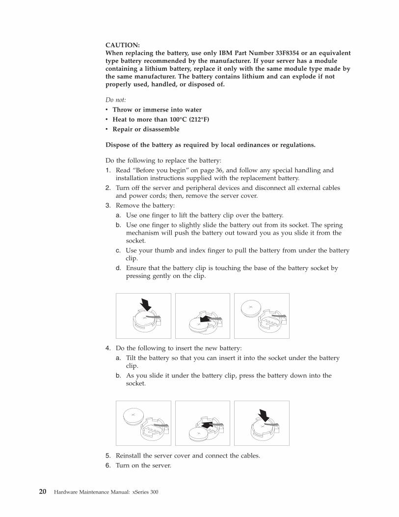
and power cords; then, remove the server cover.3. Remove the battery:
a. Use one finger to lift the battery clip over the battery.b. Use one finger to slightly slide the battery out from its socket. The spring
mechanism will push the battery out toward you as you slide it from thesocket.
c. Use your thumb and index finger to pull the battery from under the batteryclip.
d. Ensure that the battery clip is touching the base of the battery socket bypressing gently on the clip.
4. Do the following to insert the new battery:a. Tilt the battery so that you can insert it into the socket under the battery
clip.b. As you slide it under the battery clip, press the battery down into the
socket.
5. Reinstall the server cover and connect the cables.6. Turn on the server.
20 Hardware Maintenance Manual: xSeries 300

7. Start the Configuration/Setup Utility program and set configurationparameters.v Set the server date and time.v Set the power-on password.v Reconfigure your server.
Temperature checkoutProper cooling of the server is important for proper operation and server reliability.For a typical xSeries server, you should make sure:v Each of the drive bays has either a drive or a filler panel installedv Each of the power supply bays has either a power supply or a filler panel
installedv The server cover is in place during normal operationv There is at least 50 mm (2 inches) of ventilated space at the sides of the server
and 100 mm (4 inches) at the rear of the serverv The server cover is removed for no longer than 30 minutes while the server is
operatingv The processor housing cover covering the processor and memory area is
removed for no longer that ten minutes while the server is operatingv A removed hot-swap drive is replaced within two minutes of removalv Cables for optional adapters are routed according to the instructions provided
with the adapters (ensure that cables are not restricting air flow)v The fans are operating correctly and the air flow is goodv A failed fan is replaced within 48 hours
Attention:
If using AOL/2 or system supported monitoring software, and you are receiving athermal alert with no fan alert, check SYSFA1 and CPUFA2, which areunmonitored and therefore cannot generate alerts, to make certain that those fansare connected to planar power and are functional.
If the system powers itself down, the cause maybe an overheated processorcausing a thermal trip. One of your checks should be to ensure that both systemfans and both CPU fans are connected to planar power and are functional.
In addition, ensure that the environmental specifications for the server are met. See“Features and specifications” on page 4.
Note: The speed of the fans will increase if:v One fan fails.v Ambient temperature gets too high.
Diagnosing errorsTo find solutions to problems that have definite symptoms, see “Error symptoms”on page 66.
If you cannot find the problem there, go to “Starting the diagnostic programs” onpage 14 to test the server.
Chapter 3. Diagnostics 21

If you have just added new software or a new option and the server is notworking, do the following before using the error symptoms table:v Remove the software or device that you just added.v Run the diagnostic tests to determine if the server is running correctly.v Reinstall the new software or new device.
Troubleshooting the Ethernet controllerThis section provides troubleshooting information for problems that might occurwith the 10/100 Mbps Ethernet controller.
Network connection problemsIf the Ethernet controller cannot connect to the network, check the following:v Make sure that the cable is installed correctly.
The network cable must be securely attached at all connections. If the cable isattached but the problem persists, try a different cable.If you set the Ethernet controller to operate at 100 Mbps, you must use Category5 cabling.If you directly connect two workstations (without a hub), or if you are not usinga hub with X ports, use a crossover cable.
Note: To determine whether a hub has an X port, check the port label. If thelabel contains an X, the hub has an X port.
v Determine if the hub supports auto-negotiation. If not, try configuring theintegrated Ethernet controller manually to match the speed and duplex mode ofthe hub.
v Check the LAN activity light (if available) on the front of the server. The LANactivity light illuminates when the Ethernet controller sends or receives dataover the Ethernet network. If the LAN activity light is off, make sure that thehub and network are operating and that the correct device drivers are loaded.
v Make sure that you are using the correct device drivers, supplied with yourserver.
v Check for operating server-specific causes for the problem.v Make sure that the device drivers on the client and server are using the same
protocol.v Test the Ethernet controller.
The way you test the Ethernet controller depends on which operating systemyou are using (see the Ethernet controller device driver README file).
Ethernet controller troubleshooting chartYou can use the following troubleshooting chart to find solutions to 10/100 MbpsEthernet controller problems that have definable symptoms.
22 Hardware Maintenance Manual: xSeries 300

Table 2. Ethernet troubleshooting chart
Ethernet controllerproblem
Suggested Action
The server stopsrunning when loadingdevice drivers.
The PCI BIOS interrupt settings are incorrect.
Check the following:v Determine if the IRQ setting assigned to the Ethernet controller
is also assigned to another device in the Configuration/SetupUtility program.
Although interrupt sharing is allowed for PCI devices, somedevices do not function well when they share an interrupt witha dissimilar PCI device. Try changing the IRQ assigned to theEthernet controller or the other device. For example, forNetWare Versions 3 and 4 it is recommended that diskcontrollers not share interrupts with LAN controllers.
v Make sure that you are using the most recent device driveravailable from the World Wide Web.
v Run the network diagnostic program.
The LAN activity light(when available) doesnot light.
Check the following:v Make sure that you have loaded the network device drivers.v The network might be idle. Try sending data from this
workstation.v Run diagnostics on the LEDs.v The function of this LED can be changed by device driver load
parameters. If necessary, remove any LED parameter settingswhen you load the device drivers.
Data is incorrect orsporadic.
Check the following:v Make sure that you are using Category 5 cabling when
operating the server at 100 Mbps.v Make sure that the cables do not run close to noise-inducing
sources like fluorescent lights.
The Ethernet controllerstopped working whenanother adapter wasadded to the server.
Check the following:v Make sure that the cable is connected to the Ethernet controller.v Make sure that your PCI server BIOS is current.v Reseat the adapter.v Determine if the IRQ setting assigned to the Ethernet adapter is
also assigned to another device in the Configuration/SetupUtility program.
Although interrupt sharing is allowed for PCI devices, somedevices do not function well when they share an interrupt witha dissimilar PCI device. Try changing the IRQ assigned to theEthernet adapter or the other device.
The Ethernet controllerstopped workingwithout apparentcause.
Check the following:v Run diagnostics for the Ethernet controller.v Try a different connector on the hub.v Reinstall the device drivers. Refer to your operating system
documentation and to the ServerGuide information.
Chapter 3. Diagnostics 23

Ethernet controller messagesThe integrated Ethernet controller might display messages from the followingdevice drivers:v Novell NetWare
™
or IntraNetWare system open data-link interface (ODI)v Network driver interface specification (NDIS) adapter for level 4.0 (Windows
NT)
Novell NetWare or IntraNetWare system ODI driver teamingmessages
This section provides explanations of the error messages for the Novell NetWare orIntraNetWare system ODI driver, and suggested actions to resolve each problem.
Table 3. NetWare driver messages for the Ethernet controller
Message Description
Couldn’t allocate resources. Explanation: An unknown error has occurred when tryingto allocate needed resources for the AFT Module. Action:
v Check the server configuration.
v Verify that the Ethernet controller is enabled. If theEthernet controller is enabled, run the diagnosticprograms.
AFT group for primaryadapter in slot nnn alreadyexists.
Explanation: An attempt was made to rebind an adapteralready in an AFT group. Action: Check the AFT slotnumbers for existing AFT teams.
Error locating device controltable (DCT) addresses ininternal table. Make sure thatyou have loaded LANdrivers after loadingAFT.NLM.
Explanation: The bind command was entered prior toloading the device driver. The device driver must be loadedafter loading AFT.NLM, but before any bind command canbe issued. Action: Load the driver for the supportedadapter and try loading the AFT module again.
Insufficient number ofarguments specified.
Explanation: The appropriate or expected number ofparameters was not entered in a command. Action: Checkthe parameters required for the given command.
Duplicate slot numbersdetected.
Explanation: An attempt has been made to bind the sameslot number more than once. Action: Check the slotnumbers entered during the bind. Adapter slot numbersmust be valid and unique.
’xxx’ is not supported forAFT team.
Explanation: A bind command has been issued for adaptersnot supported by AFT.NLM. Action: Make sure that youattempt to bind only adapters supported by AFT.NLM.
Primary and Secondaryadapters do not match. AFTgroup is not created.
Explanation: A bind command was entered for an adapterteam that is a combination of server and client adapters. AnAFT team must be a grouping of the same classification ofadapter. Action: Verify that all the adapters bound in ateam are of the same classification.
Requested number ofSecondary cards are notfound.
Explanation: The number of adapters specified in the bindcommand could not be located. Action: Verify the numbersand slot locations of the adapters to be bound.
24 Hardware Maintenance Manual: xSeries 300
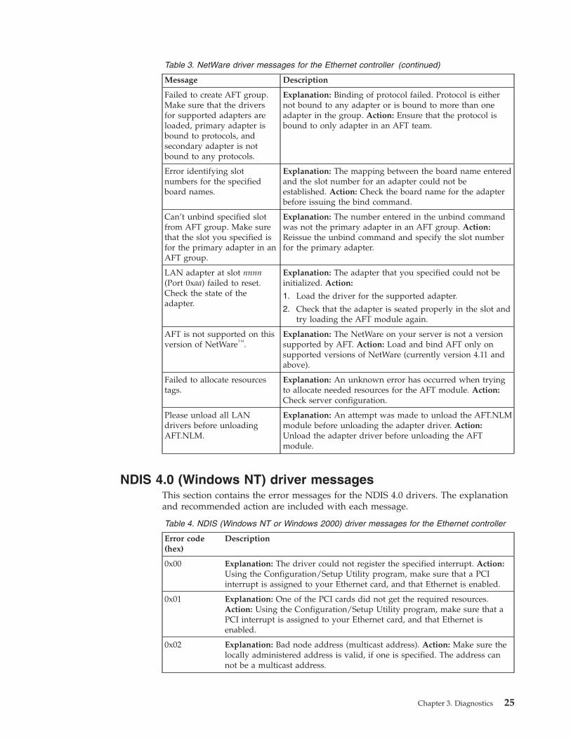
Table 3. NetWare driver messages for the Ethernet controller (continued)
Message Description
Failed to create AFT group.Make sure that the driversfor supported adapters areloaded, primary adapter isbound to protocols, andsecondary adapter is notbound to any protocols.
Explanation: Binding of protocol failed. Protocol is eithernot bound to any adapter or is bound to more than oneadapter in the group. Action: Ensure that the protocol isbound to only adapter in an AFT team.
Error identifying slotnumbers for the specifiedboard names.
Explanation: The mapping between the board name enteredand the slot number for an adapter could not beestablished. Action: Check the board name for the adapterbefore issuing the bind command.
Can’t unbind specified slotfrom AFT group. Make surethat the slot you specified isfor the primary adapter in anAFT group.
Explanation: The number entered in the unbind commandwas not the primary adapter in an AFT group. Action:Reissue the unbind command and specify the slot numberfor the primary adapter.
LAN adapter at slot nnnn(Port 0xaa) failed to reset.Check the state of theadapter.
Explanation: The adapter that you specified could not beinitialized. Action:
1. Load the driver for the supported adapter.
2. Check that the adapter is seated properly in the slot andtry loading the AFT module again.
AFT is not supported on thisversion of NetWare™.
Explanation: The NetWare on your server is not a versionsupported by AFT. Action: Load and bind AFT only onsupported versions of NetWare (currently version 4.11 andabove).
Failed to allocate resourcestags.
Explanation: An unknown error has occurred when tryingto allocate needed resources for the AFT module. Action:Check server configuration.
Please unload all LANdrivers before unloadingAFT.NLM.
Explanation: An attempt was made to unload the AFT.NLMmodule before unloading the adapter driver. Action:Unload the adapter driver before unloading the AFTmodule.
NDIS 4.0 (Windows NT) driver messagesThis section contains the error messages for the NDIS 4.0 drivers. The explanationand recommended action are included with each message.
Table 4. NDIS (Windows NT or Windows 2000) driver messages for the Ethernet controller
Error code(hex)
Description
0x00 Explanation: The driver could not register the specified interrupt. Action:Using the Configuration/Setup Utility program, make sure that a PCIinterrupt is assigned to your Ethernet card, and that Ethernet is enabled.
0x01 Explanation: One of the PCI cards did not get the required resources.Action: Using the Configuration/Setup Utility program, make sure that aPCI interrupt is assigned to your Ethernet card, and that Ethernet isenabled.
0x02 Explanation: Bad node address (multicast address). Action: Make sure thelocally administered address is valid, if one is specified. The address cannot be a multicast address.
Chapter 3. Diagnostics 25

Table 4. NDIS (Windows NT or Windows 2000) driver messages for the Ethernetcontroller (continued)
Error code(hex)
Description
0x03 Explanation: Failed self-test. Action: Make sure a cable is attached to theEthernet connector.
0x0D Explanation: Could not allocate enough memory for transmit queues.Action:
1. From the Windows NT desktop, select Start → Control Panel →Networks → Adapters.
2. Select your IBM Ethernet adapter from the list.
3. Select Properties → Advanced.
4. Lower the resource values that apply to the transmit queue.
0x0E Explanation: Could not allocate enough memory for receive queue. Action:
1. From the Windows NT desktop, select Start →Control Panel →Networks→Adapters.
2. Select your IBM Ethernet adapter from the list.
3. Select Properties →Advanced.
4. Lower the resource values that apply to the receive queue.
0x0F Explanation: Could not allocate enough memory for other structures.Action:
1. From the Windows NT desktop, select Start → Control Panel →Networks → Adapters.
2. Select your IBM Ethernet adapter from the list.
3. Select Properties →Advanced.
4. Lower the value for the resource named in the message.
0x10 Explanation: Did not find any Ethernet controllers. Action: Using theConfiguration/Setup Utility program, make sure that Ethernet is enabled.
0x11 Explanation: Multiple Ethernet controllers found, but none matched therequired ID. Action: Using the Configuration/Setup Utility program, makesure that Ethernet is enabled.
0x13 Explanation: Did not find any Ethernet controllers that matched therequired subven/subdev. Action: Using the Configuration/Setup Utilityprogram, make sure that Ethernet is enabled.
0x16 Explanation: Single adapter found, but multiple instances tried to load.Action: Using the Configuration/Setup Utility program, make sure thatEthernet is enabled, and that the slot containing the IBM xSeries 20010/100 Ethernet Adapter or the IBM 10/100 Etherjet PCI adapter isenabled.
0x17 Explanation: Slot parameter not specified in the registry. Action: Removethe adapter driver and reinstall it.
26 Hardware Maintenance Manual: xSeries 300

Ethernet teaming messages:This section displays the messages associated with Ethernet teaming.
Table 5. NDIS (Windows NT or Windows 2000) driver teaming messages for the Ethernetcontroller
Event ID Type Description
01 Error Explanation: Team name and physical adapter name arethe same. This is an invalid configuration. Action:Reconfigure the adapter team by double-clicking thePROSet icon in the control panel.
02 Error Explanation: Unable to allocate required resources.Action: Free some memory resources and restart.
03 Error Explanation: Unable to read required registryparameters. Action: Reconfigure the adapter team bydouble-clicking the PROSet icon in the control panel.
04 Error Explanation: Unable to bind to physical adapter. Action:Reconfigure the adapter team by double-clicking thePROSet icon in the control panel.
05 Error Explanation: Unable to initialize an adapter team.Action: Reconfigure the adapter team by double-clickingthe PROSet icon in the control panel.
06 Informational Explanation: Team nn. Primary adapter is initialized.Action: None.
07 Informational Explanation: Team nn. Secondary adapter is initialized.Action: None.
08 Informational Explanation: Team nn. Virtual adapter or Team isinitialized. Action: None.
09 Informational Explanation: Team nn. Primary adapter is switchingover. Action: None.
10 Warning Explanation: Team nn. Adapter link down. Action:Make sure the adapter is functioning properly.
11 Informational Explanation: Team nn. Secondary adapter took over.Action: None.
12 Warning Explanation: Team nn. Secondary adapter is deactivatedfrom the Team. Action: Make sure the secondaryadapter is functioning properly and that the adaptercable is securely connected to the LAN.
13 Informational Explanation: Team nn. Secondary adapter has rejoinedthe Team. Action: None.
14 Informational Explanation: Team nn. Secondary adapter link is up.Action: None.
15 Error Explanation: Team nn. The last adapter has lost its link.Network connection has been lost. Action: Shut downthe server and replace the adapters; then, restart theserver to reestablish the connection.
16 Informational Explanation: Team nn. An adapter has reestablished thelink. Network connection has been restored. Action:None.
17 Informational Explanation: Team nn. Preferred primary adapter hasbeen detected. Action: None.
Chapter 3. Diagnostics 27
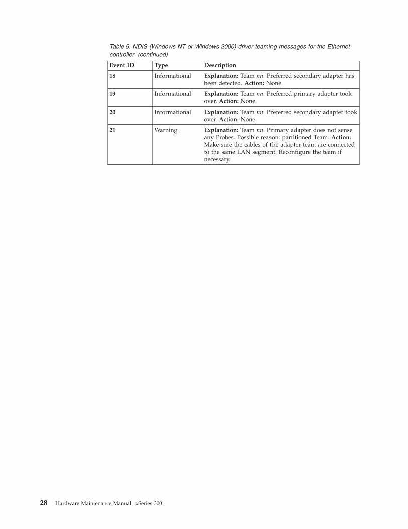
Table 5. NDIS (Windows NT or Windows 2000) driver teaming messages for the Ethernetcontroller (continued)
Event ID Type Description
18 Informational Explanation: Team nn. Preferred secondary adapter hasbeen detected. Action: None.
19 Informational Explanation: Team nn. Preferred primary adapter tookover. Action: None.
20 Informational Explanation: Team nn. Preferred secondary adapter tookover. Action: None.
21 Warning Explanation: Team nn. Primary adapter does not senseany Probes. Possible reason: partitioned Team. Action:Make sure the cables of the adapter team are connectedto the same LAN segment. Reconfigure the team ifnecessary.
28 Hardware Maintenance Manual: xSeries 300

Chapter 4. Configuring the server
The following configuration programs are provided with your server:v Configuration/Setup Utility
This program is part of the basic input/output system (BIOS) code that comeswith your server. You can use this program to configure the serial connectorassignment, change the drive startup sequence, set the date and time, and setpasswords. For information on how to start this utility see, “Starting theConfiguration/Setup Utility program” on page 30.
v SCSISelect Utility
With the SCSISelect Utility program, you can configure the devices that areattached to the SCSI adapter (provided in some models). Use this program tochange default values, resolve configuration conflicts, and perform a low-levelformat on a SCSI hard disk drive. For information on how to start this utility,see “Starting the SCSISelect utility program” on page 30.
v PXE Boot Agent Utility
The Preboot eXecution Environment (PXE) Boot Agent Utility program is part ofthe BIOS code that comes with the server. You can use this program to changenetwork startup (boot) protocols and startup order, to select operating-systemwake-up support, and to set menu wait times. For information on how to startthis utility, see “Starting the PXE boot agent utility program” on page 31.
v ServerGuide™ CDs
The ServerGuide CDs include software setup and installation tools that arespecifically designed for IBM xSeries 300 servers. You can use these CDs duringthe initial installation of your server to configure the server hardware and tosimplify your NOS installation. The ServerGuide CDs also contain a collection ofapplication programs, which you can install after your server is up and running.See “Using the ServerGuide CDs” on page 32 for more information.
© Copyright IBM Corp. 2000 29

Starting the utility programsThis section provides the instructions for starting the utility programs. For moredetailed information about these utility programs, refer to the User’s Reference onthe IBM xSeries Documentation CD.
Using the Configuration/Setup Utility programConfiguration/Setup is a menu-driven utility that is part of the BIOS code thatcomes with your server. You can use it to:v Configure serial connector assignmentsv Change the drive startup sequencev Enable USB keyboard and mouse supportv Resolve configuration conflictsv Set the date and timev Set passwords
Starting the Configuration/Setup Utility programComplete the following steps to start the Configuration/Setup Utility program:1. Turn on the server and watch the monitor screen.2. When the message Press F1 for Configuration/Setup appears, press F1.3. Follow the instructions that appear on the screen.
Using the SCSISelect utility program (some models)SCSISelect is a built-in, menu-driven configuration utility program that you canuse to:v View the default SCSI IDsv Locate and correct configuration conflicts
Note: If your server has a redundant arrays of independent disks (RAID) adapterinstalled, use the configuration method that is supplied with the RAIDadapter to view or change SCSI settings for devices attached to the adapter.
Starting the SCSISelect utility programComplete the following steps to start the SCSISelect Utility program:1. Turn on the server.2. When the <<< Press <CTRL><A> for SCSISelect™ Utility! >>> prompt
appears, press Ctrl+A.3. When the Would you like to configure the host adapter or run the SCSI
disk utility? question appears, make your selection and press Enter.4. Use the arrow keys to select a choice from the menu.
v Press Esc to exit the SCSISelect Utility program.v Press the F5 key to switch between color and monochrome modes (if your
monitor permits).5. Follow the instructions on the screen to change the settings of the selected
items; then, press Enter.
30 Hardware Maintenance Manual: xSeries 300

Using the PXE boot agent utility programThe PXE boot agent is a built-in, menu-driven configuration utility program thatyou can use to:v Change network startup (boot) protocolsv Change startup (boot) orderv Select whether or not to display setup promptv Set menu wait timev Select OS wake up support
Starting the PXE boot agent utility programThe following sections provide the instructions needed to start the PXE Boot AgentUtility and descriptions of the menu choices available.
To start the PXE Boot Agent Utility program:1. Turn on the server.2. When the Initializing Intel (R) Boot Agent Version X.X.XX PXE 2.0 Build
XXX (WfM 2.0) prompt appears, press Ctrl+S.
Note: By default you will have two seconds after the prompt appears on thescreen to press Ctrl+S.
3. Use the arrow keys or press Enter to select a choice from the menu.v Press Esc to return to the previous menu.v Press the F4 key to exit.
4. Follow the instructions on the screen to change the settings of the selecteditems; then, press Enter.
Chapter 4. Configuring the server 31

Using the ServerGuide CDsThe ServerGuide CDs provide state-of-the-art programs to detect the server modeland hardware options that are installed, configure the server hardware, providedevice drivers, and install your network operating system (NOS).
Note: If the ServerGuide CD does not start, see “ServerGuide startup problems” onpage 33.
1. Insert the Setup and Installation CD, and restart the server.2. Follow the instructions on the screens to:
a. Select your language.b. Select your keyboard layout and country.c. View the Overview to learn about ServerGuide features.d. View the README file to review installation tips about your NOS and
adapter.e. Start the setup and hardware configuration programs.f. Start the NOS installation. You will need your copy of the NOS CD.
Note: For information on the supported NOS versions, refer to the Setup andInstallation CD label.
32 Hardware Maintenance Manual: xSeries 300

ServerGuide startup problemsLook for the symptom in the left column of the chart. Probable solutions to theproblem are in the right column.
Table 6. ServerGuide startup problems
Setup Suggested action
Setup and Installation CDwill not start.
v Ensure that the system is a supported server with a startable (bootable) CD-ROMdrive.
v If the startup (boot) sequence settings have been altered, be sure the CD-ROM is firstin the boot sequence.
ServeRAID™ programcannot view all installeddrives - or - cannotinstall NOS.
If you installed an optional ServeRAID adapter:v Ensure that there are no duplicate SCSI IDs or IRQ assignments.v Ensure that the hard disk drive is connected properly.
The Operating SystemInstallation programcontinuously loops.
Free up more space on the hard disk drive.
ServerGuide will notstart your NOS CD.
Ensure that the NOS CD you have is supported by ServerGuide. See the Setup andInstallation CD label for a list of NOS versions supported.
Cannot install NOS -option is grayed out.
Either there is no logical drive defined (ServeRAID systems) or the ServerGuide systempartition is not present. Run the ServerGuide setup and configuration program andensure that setup is complete
Table 7. System updates and applications CD
System updates andapplications CD
Suggested action
Get “time out” or“Unknown host” errors
Ensure that you have access to the Internet through FTP directly.
Chapter 4. Configuring the server 33

34 Hardware Maintenance Manual: xSeries 300

Chapter 5. Installing Options
This chapter provides basic information that is needed to install hardware optionsin your server. For more detailed installation information, refer to the User’sReference on the IBM xSeries Documentation CD.
© Copyright IBM Corp. 2000 35

Major components of the xSeries 300 serverThe following illustration shows the locations of major components in your server.
Note: The illustrations in this document might differ slightly from your hardware.
Microprocessor
Fans
Hard disk drivefiller panel
Hard disk drive
Memory module
Air baffle
Heat sink
Clip
Blanks
Before you beginBefore you begin to install options in the server, read the following information:v Become familiar with the safety and handling guidelines provided in:
– “Safety information” on page 75;– “Handling electrostatic discharge-sensitive devices” on page 78; and– “Safety notices (multi-lingual translations)” on page 79.
These guidelines will help you work safely while working with the server oroptions.
36 Hardware Maintenance Manual: xSeries 300

v Make sure that you have an adequate number of properly grounded electricaloutlets for the server, monitor, and any other options that you intend to install.
v Back up all important data before you make changes to disk drives.v For a list of supported options for the 200, refer to
http://www.ibm.com/pc/us/compat on the World Wide Web.
Working inside the server with the power onThe server is designed with safety in mind. Follow these guidelines when youwork inside a server that is turned on:v Avoid loose-fitting clothing on your forearms. Button long-sleeved shirts before
working inside the server; do not wear cuff links while you are working insidethe server.
v Do not allow your necktie to hang inside the server.v Remove jewelry, such as bracelets, necklaces, rings, and loose-fitting wrist
watches.v Remove items from your shirt pocket (such as pens or pencils) that could fall
into the server as you lean over it.v Avoid dropping any metallic objects, such as paper clips, hair pins, or screws,
into the server.
System reliability considerationsTo help ensure proper cooling and system reliability, make sure that:v Each of the drive bays either has a drive, or a filler panel and electromagnetic
compatibility (EMC) shield installed.v There is space around the server to allow the server cooling system to work
properly. Leave about 127 mm (5 in.) of space around the front and rear of theserver.
v Cables for optional adapters are routed according to the instructions that areprovided with the adapters.
v A failed fan is replaced within 1 hour.
Handling static-sensitive devicesAttention: Static electricity can damage electronic devices and your system. Toavoid damage, keep static-sensitive devices in their static-protective bag until youare ready to install them.
To reduce the possibility of electrostatic discharge, observe the followingprecautions:v Limit your movement. Movement can cause static electricity to build up around
you.v Handle the device carefully, holding it by its edges or its frame.v Do not touch solder joints, pins, or exposed printed circuitry.v Do not leave the device where others can handle and possibly damage the
device.v While the device is still in its anti-static package, touch it to an unpainted metal
part of the system unit for at least two seconds. (This drains static electricityfrom the package and from your body.)
v Remove the device from its package and install it directly into your system unitwithout setting it down. If it is necessary to set the device down, place it on its
Chapter 5. Installing Options 37
static-protective package. (If your device is an adapter, place it component sideup.) Do not place the device on your system unit cover or on a metal table.
v Take additional care when handling devices during cold weather as heatingreduces indoor humidity and increases static electricity.
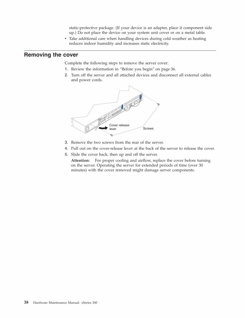
Removing the coverComplete the following steps to remove the server cover:1. Review the information in “Before you begin” on page 36.2. Turn off the server and all attached devices and disconnect all external cables
and power cords.
Cover releaselever Screws
3. Remove the two screws from the rear of the server.4. Pull out on the cover-release lever at the back of the server to release the cover.5. Slide the cover back, then up and off the server.
Attention: For proper cooling and airflow, replace the cover before turningon the server. Operating the server for extended periods of time (over 30minutes) with the cover removed might damage server components.
38 Hardware Maintenance Manual: xSeries 300

System board
To remove the system board:
Note: Read“Safety information” on page 75 and “Before you begin” on page 36.1. Power off the server.2. Remove the cover. See “Removing the cover” on page 38.3. Disconnect all cables from the system board.4. Remove the adapter retaining latch (see “Removing a microprocessor” on
page 49).5. Remove the microprocessors. See “Removing a microprocessor” on page 49.6. Remove the memory modules. See “Installing DIMMs” on page 45.7. Remove screws from the system board.8. Remove the four screws from the rear of the server.9. Pull up on the system board to remove from the chassis.
Chapter 5. Installing Options 39
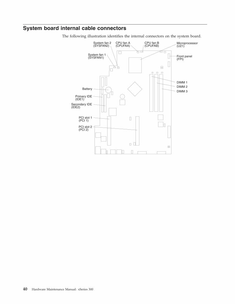
System board internal cable connectorsThe following illustration identifies the internal connectors on the system board.
Microprocessor(U21)
DIMM 1DIMM 2
DIMM 3Battery
PCI slot 1(PCI 1)
PCI slot 2(PCI 2)
CPU fan A(CPUFAA)
CPU fan B(CPUFAB)
Front panel(FPI)
System fan 2(SYSFAN2)
System fan 1(SYSFAN1)
Secondary IDE(IDE2)
Primary IDE(IDE1)
40 Hardware Maintenance Manual: xSeries 300
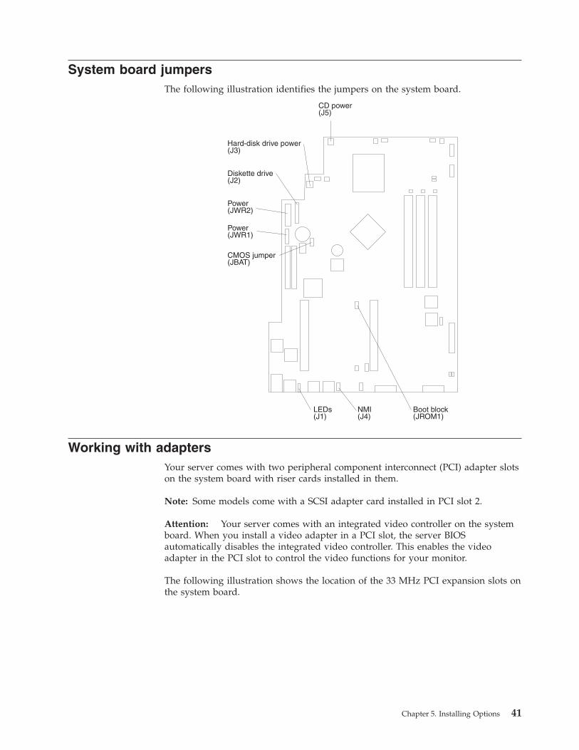
System board jumpersThe following illustration identifies the jumpers on the system board.
Working with adaptersYour server comes with two peripheral component interconnect (PCI) adapter slotson the system board with riser cards installed in them.
Note: Some models come with a SCSI adapter card installed in PCI slot 2.
Attention: Your server comes with an integrated video controller on the systemboard. When you install a video adapter in a PCI slot, the server BIOSautomatically disables the integrated video controller. This enables the videoadapter in the PCI slot to control the video functions for your monitor.
The following illustration shows the location of the 33 MHz PCI expansion slots onthe system board.
Chapter 5. Installing Options 41

Note: The illustrations in this document might differ slightly from your hardware.
PCI slot 1(PCI 1)
PCI slot 2(PCI 2)
Adapter considerationsBefore you install adapters, review the following:v Locate the documentation that comes with the adapter and follow those
instructions in addition to the instructions in this chapter.v If you need to change the switch settings or jumper settings on your adapter,
follow the instructions that come with the adapter.v You can install 32-bit full-length or half-length adapters in the expansion slots.
Full-length adapters are installed in slot 1 only; half-length adapters are installedin either slot 1 or 2.
v Your server supports 5.0 V and universal PCI adapters; it does not support 3.3V only adapters.
v Your server uses a rotational interrupt technique to configure PCI adapters. Youcan use this technique to install PCI adapters that currently do not supportsharing of PCI interrupts.
v The system scans PCI slots to assign system resources. By default the systemstarts (boots) the CD-ROM and diskette drives first. Then it starts PCI slot 2, PCIslot 1, and the integrated Ethernet.
Note: You can use the Configuration/Setup Utility program to change the bootprecedence for your server. Select Start Options from theConfiguration/Setup Utility program main menu.
Installing an adapterComplete the following steps to install an adapter:
Attention: When you handle static-sensitive devices, take precautions to avoiddamage from static electricity. For details on handling these devices, see “Handlingstatic-sensitive devices” on page 37.
42 Hardware Maintenance Manual: xSeries 300

1. Review the information in ″“Safety information” on page 75″, and “Before youbegin” on page 36.
2. Turn off the server and peripheral devices.3. Remove all external cables from the server.4. Remove the server cover.
Cover releaselever Screws
5. Remove the expansion-slot clip that holds the expansion-slot cover in place bysliding it upward and off the frame of the server.
Note: The illustrations in this document might differ slightly from yourhardware.
Retentionlatch
Tab
Adapter
Expansion-slot cover
Expansion-slotclip
Expansionslot
6. Remove the expansion-slot cover.7. Refer to the documentation that comes with your adapter for any cabling
instructions.Attention: You should route adapter cables before you install the adapter.
8. Set any jumpers or switches as described by the adapter manufacturer.9. Install the adapter:
Chapter 5. Installing Options 43

Note: When installing an adapter into slot 2, skip steps a and d.a. Open the adapter-retention latch by pushing the blue tab to release it.
Then, push the latch up to the full open position.b. Carefully grasp the adapter by its top edge or upper corners, and align it
with the connector on the PCI riser-card.c. Press the adapter firmly into the riser card connector.
Attention: When you install an adapter, be sure the adapter is correctlyseated in the riser-card connector before you turn on the server.Improperly seated adapters might cause damage to the system board, theriser card, or the adapter.
d. Push down on the blue adapter retention latch until it clicks into place,securing the adapter.
e. Replace the expansion-slot clip by sliding it down until it latches into placeand holds the adapter securely.
10. Connect the internal cables to the adapter.Attention: Route cables so that they do not block the flow of air from thefans.
11. If you have other options to install or remove, do so now.12. Replace the cover on the server; then, install the server in the rack and
connect all external cables. For more information, see “Installing the cover” onpage 53, and the ″Rack installation″ flyer for instructions.
Hard disk drivesDepending on the model, your server supports two SCSI or two IDE hard diskdrives.
Installing or replacing a hard disk driveComplete the following steps to install or replace a hard disk drive:
Attention: When you handle static-sensitive devices, take precautions to avoiddamage from static electricity. For details on handling these devices, see “Handlingstatic-sensitive devices” on page 37.1. Inspect the drive for any signs of damage.2. Review the information in ″“Safety information” on page 75″, and “Before you
begin” on page 36.3. Check the instructions that come with the drive for more information about
installing your drive.
Notes:
a. If you are installing an IDE hard disk drive, you must set the drive toprimary (master) or secondary (subordinate), depending on theconfiguration of your server. See the documentation that comes with thedrive for instructions.
b. If you are installing a SCSI hard disk drive, refer to the documentation thatcomes with your drive before installing it.
4. Turn off the server and peripheral devices and disconnect all external cablesand power cords.
5. Remove the server cover.
Note: If you are replacing a failing hard disk drive, remove the fans behind thedrive bay in which you are working; then, disconnect the power and
44 Hardware Maintenance Manual: xSeries 300

signal cables from the hard disk drive. For information on how toremove the fan, see ″Fan assembly replacement″, on the IBM xSeriesDocumentation CD.
6. Remove the filler panel from one of the hard disk drive bays.7. Install the new hard disk drive in the drive bay:
a. Slide the drive into the bay and align the screw holes in the drive with thescrew holes in the server chassis.
b. Use a screwdriver to secure the hard disk drive to the server chassis.
Filler panel
Hard disk drive
c. Connect the signal cable and power cable to the rear of the drive. Ensurethat the cables do not obstruct the fan behind the drive bay.
8. If you have other options to install or remove, do so now.9. Replace the server cover. See “Installing the cover” on page 53.
Working with DIMMsYour xSeries 300 server supports 128 MB, 256 MB, and 512 MB DIMMs. See theServerProven list at http://www.ibm.com/pc/compat for a list of DIMMs for usewith your server.
Install additional DIMMs in DIMM connector 2 first, then in DIMM connector 3.(See the following illustration for memory connector locations.)
Note: The illustrations in this document might differ slightly from your hardware.
Installing DIMMsComplete the following steps to install a DIMM:1. Review the safety precautions beginning on page 111.2. Turn off the server and peripheral devices.3. Remove all external cables from the server; then, remove the cover. For more
information, see “Removing the cover” on page 38.Attention: When you handle static-sensitive devices, take precautions toavoid damage from static electricity. For details on handling these devices, referto “Handling static-sensitive devices” on page 37.
4. If necessary, remove the PCI adapter in slot 2 for easier access to the DIMMconnectors.
Chapter 5. Installing Options 45

5. Touch the static-protective package containing the DIMM to any unpaintedmetal surface on the server. Then, remove the DIMM from the package.
Connector 1
Connector 2Connector 3
Connector 4
Attention: To avoid breaking the retaining clips or damaging the DIMMconnectors, handle the clips gently.
6. Install the DIMM in the connector.Attention: To prevent damage to the DIMM connectors, do not force theDIMM into the connector.a. Turn the DIMM so that the index slots align correctly with the connector.
Note: The DIMM has two index slots, one in the center and the other onthe left half of the DIMM connector edge.
b. Insert the DIMM into the connector by pressing on both corners of theDIMM at the same time. Be sure to press it straight into the connector.
c. When installing a DIMM, be sure that no gap exists between the DIMM andthe retaining clips. If a gap does exist between the DIMM and the retainingclips, remove the DIMM; then, reinsert it properly.
7. If you removed the PCI adapter as described in step 4, install it now.8. If you have other options to install or remove, do so now.9. Replace the server cover. For more information on replacing the cover, see
“Installing the cover” on page 53.
46 Hardware Maintenance Manual: xSeries 300
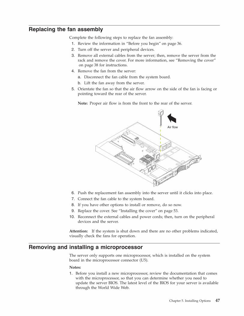
Replacing the fan assemblyComplete the following steps to replace the fan assembly:1. Review the information in “Before you begin” on page 36.2. Turn off the server and peripheral devices.3. Remove all external cables from the server; then, remove the server from the
rack and remove the cover. For more information, see “Removing the cover”on page 38 for instructions.
4. Remove the fan from the server:a. Disconnect the fan cable from the system board.b. Lift the fan away from the server.
5. Orientate the fan so that the air flow arrow on the side of the fan is facing orpointing toward the rear of the server.
Note: Proper air flow is from the front to the rear of the server.
Air flow
6. Push the replacement fan assembly into the server until it clicks into place.7. Connect the fan cable to the system board.8. If you have other options to install or remove, do so now.9. Replace the cover. See “Installing the cover” on page 53.
10. Reconnect the external cables and power cords; then, turn on the peripheraldevices and the server.
Attention: If the system is shut down and there are no other problems indicated,visually check the fans for operation.
Removing and installing a microprocessorThe server only supports one microprocessor, which is installed on the systemboard in the microprocessor connector (U5).
Notes:
1. Before you install a new microprocessor, review the documentation that comeswith the microprocessor, so that you can determine whether you need toupdate the server BIOS. The latest level of the BIOS for your server is availablethrough the World Wide Web.
Chapter 5. Installing Options 47

2. For a list of supported operating systems, seehttp://www.ibm.com/pc/us/compat/ on the World Wide Web.
Note: The illustrations in this document might differ slightly from your hardware
Attention: To avoid damage and ensure correct server operation when youinstall a new microprocessor, use a microprocessor that has the same cache sizeand type, and the same clock speed. Microprocessor internal clock frequencies andexternal clock frequencies must be identical. See the ServerProven list athttp://www.ibm.com/pc/compat for a list of microprocessors for use with yourserver.
48 Hardware Maintenance Manual: xSeries 300
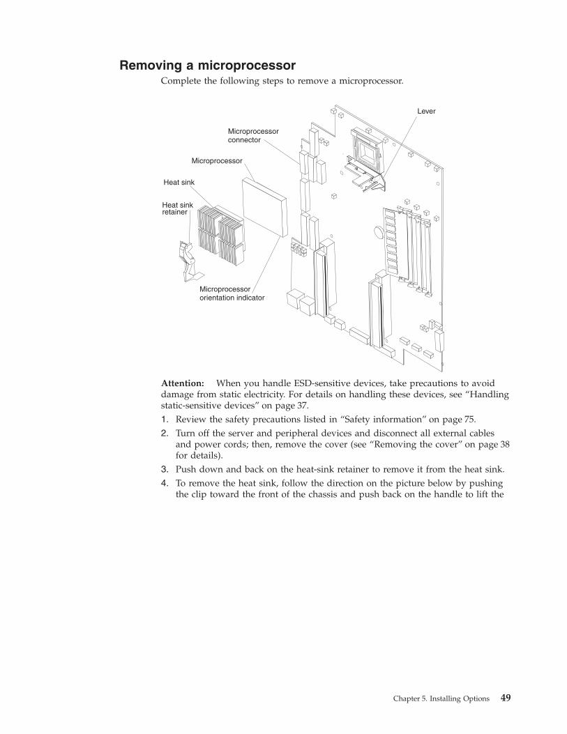
Removing a microprocessorComplete the following steps to remove a microprocessor.
Microprocessor
Microprocessorconnector
Microprocessororientation indicator
Lever
Heat sinkretainer
Heat sink
Attention: When you handle ESD-sensitive devices, take precautions to avoiddamage from static electricity. For details on handling these devices, see “Handlingstatic-sensitive devices” on page 37.1. Review the safety precautions listed in “Safety information” on page 75.2. Turn off the server and peripheral devices and disconnect all external cables
and power cords; then, remove the cover (see “Removing the cover” on page 38for details).
3. Push down and back on the heat-sink retainer to remove it from the heat sink.4. To remove the heat sink, follow the direction on the picture below by pushing
the clip toward the front of the chassis and push back on the handle to lift the
Chapter 5. Installing Options 49

front of the clip.
If the handle breaks, remove the handle by placing a screw driver in betweenboth sides of the handle as in the picture above, and twist the screw driver tobreak off the handle to relieve the pressure from the clip to the heat sink, as inthe picture below.
CAUTION:Exercise extreme caution when removing the heatsink. Be careful not todamage the system board or processor beneath.
50 Hardware Maintenance Manual: xSeries 300

Note: Once you remove the heat sink from the microprocessor, you mustreplace it with a new device.
Pull out and lift up the release lever and remove the microprocessor from theconnector. Store the microprocessor in a static-protective bag for possible futureuse.
5. If you are installing a new microprocessor, continue with step 4 in “Installing amicroprocessor”.
Installing a microprocessorComplete the following steps to install a microprocessor:
Attention: When you handle ESD-sensitive devices, take precautions to avoiddamage from static electricity. For details on handling these devices, refer to IBMWeb site http://www.ibm.com/ and use a search term of ESD.1. Review the safety precautions listed in “Safety information” on page 75.2. Turn off the server and peripheral devices and disconnect all external cables
and power cords; then, remove the cover (see “Removing the cover” on page 38for details).
3. Install the microprocessor:a. Touch the static-protective package containing the new microprocessor to
any unpainted metal surface on the server; then, remove the microprocessorfrom the package.
b. Pull out and lift up on the microprocessor release lever to unlock themicroprocessor connector.
c. Orient the microprocessor over the microprocessor connector as shown inthe following illustration. Carefully press the microprocessor into theconnector.
Microprocessor
Microprocessorconnector
Microprocessororientation indicator
Lever
Note: Do not use excessive force when pressing the microprocessor into theconnector.
4. Push the microprocessor release lever down to lock the microprocessor into theconnector.
5. Install a heat sink.
Chapter 5. Installing Options 51

v
Microprocessor
Microprocessorconnector
Microprocessororientation indicator
Lever
Heat sinkretainer
Heat sink
a. Peel the plastic protective strip off the bottom of the heat sink. Make surethe square of thermal material is still on the bottom of the heat sink; ifnot, replace the it with a new heat sink.
b. Align and place the heat sink on top of the microprocessor.c. Align and push the heat-sink retainer through the groove in the center of
the fan sink.d. Insert a small, flat-bladed screwdriver into the tab on the heat-sink
retainer.e. Press the screwdriver down to snap the heat-sink retainer into place.f. Connect the heat-sink power cable to the microprocessor heat-sink
connector (CPUFA1) on the system board. See “System board internalcable connectors” on page 40 for the location of the microprocessorheat-sink connector.
6. If you have other options to install or remove, do so now; otherwise, replacethe cover. See “Installing the cover” on page 53 for instructions on installing thecover.
7. Reconnect the external cables and power cords; then, turn on the peripheraldevices and the server.
52 Hardware Maintenance Manual: xSeries 300

Installing the coverComplete the following steps to install the server cover:1. Install the cover by placing it into position and sliding it forward. Make sure
that the cover engages the tabs at the front and rear of the server.Attention: Before sliding the cover forward, place the cover over 80% of thebox, to ensure that cables are covered, and make sure that all of the tabs on thecover will engage the ledge at the front of the server properly. If all the tabs donot engage the ledge properly, it will be extremely difficult to remove the coverlater.
Screws
2. Install the screws to secure the cover as shown.3. Install the server in the rack. See the ″Rack installation instuctions″ included
with your server documentation for instructions.4. Connect the power cord and all external cables to the server, and then plug the
power cords into properly grounded electrical outlets. See “Working withcables” on page 54 for connector locations.
Chapter 5. Installing Options 53

Working with cablesThere are many different cables that connect to the rear of the server. These includeEthernet, USB, video, pointing device, serial, and power cables. This sectiondescribes how to manage these cables.
Notes:
1. Refer to the following illustration to locate the connectors on the back of yourserver.
2. The illustrations in this document might differ slightly from your hardware.
Ethernet 1 connector
Ethernet 2 connector
Serialconnector
USB 1
USB 2 Videoconnector
Mouse or auxiliarypointing device connector
Keyboard connector
To effectively manage the cables on this server, keep groups of cables securedtogether, and do not run cables across the back of the server.
Notes:
1. Use cable ties to bundle like cables together.2. Use hook-and-loop straps to secure the cable bundles to the vertical rails of the
rack.3. When possible, separate data and power cables. For more information on cable
routing, see the cabling instructions for your xSeries 300 server on the WorldWide Web at http://www.pc.ibm.com/support.
4. Do not secure cables too tightly. Overtightening can cause internal damage tocables.
54 Hardware Maintenance Manual: xSeries 300
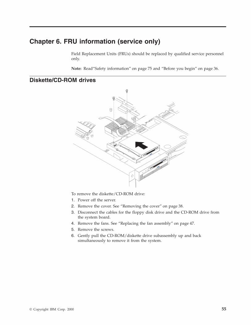
Chapter 6. FRU information (service only)
Field Replacement Units (FRUs) should be replaced by qualified service personnelonly.
Note: Read“Safety information” on page 75 and “Before you begin” on page 36.
Diskette/CD-ROM drives
To remove the diskette/CD-ROM drive:1. Power off the server.2. Remove the cover. See “Removing the cover” on page 38.3. Disconnect the cables for the floppy disk drive and the CD-ROM drive from
the system board.4. Remove the fans. See “Replacing the fan assembly” on page 47.5. Remove the screws.6. Gently pull the CD-ROM/diskette drive subassembly up and back
simultaneously to remove it from the system.
© Copyright IBM Corp. 2000 55
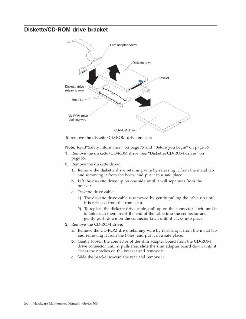
Diskette/CD-ROM drive bracket
Diskette drive
Slim adapter board
Bracket
CD-ROM drive
CD-ROM driveretaining wire
Diskette driveretaining wire
Metal tab
To remove the diskette/CD-ROM drive bracket:
Note: Read“Safety information” on page 75 and “Before you begin” on page 36.1. Remove the diskette/CD-ROM drive. See “Diskette/CD-ROM drives” on
page 55.2. Remove the diskette drive:
a. Remove the diskette drive retaining wire by releasing it from the metal taband removing it from the holes, and put it in a safe place.
b. Lift the diskette drive up on one side until it will separates from thebracket.
c. Diskette drive cable:1) The diskette drive cable is removed by gently pulling the cable up until
it is released from the connector.2) To replace the diskette drive cable, pull up on the connector latch until it
is unlocked; then, insert the end of the cable into the connector andgently push down on the connector latch until it clicks into place.
3. Remove the CD-ROM drive:a. Remove the CD-ROM drive retaining wire by releasing it from the metal tab
and removing it from the holes, and put it in a safe place.b. Gently loosen the connector of the slim adapter board from the CD-ROM
drive connector until it pulls free; slide the slim adapter board down until itclears the notches on the bracket and remove it.
c. Slide the bracket toward the rear and remove it.
56 Hardware Maintenance Manual: xSeries 300

Power supply - AC
To remove the power supply:
Note: Read“Safety information” on page 75 and “Before you begin” on page 36.1. Power off the server.2. Remove the cover. See “Removing the cover” on page 38.3. Disconnect the cables that connect the power supply to the system board.4. Remove the screws (2) from the side of the chassis.5. Remove the screws at the back of the chassis and power supply.6. Slide the power supply away from the side of the chassis and lift up to remove.
Power supply - DCUse this documentation in conjunction with the xSeries documentation that comeswith your server. The information contained in this document replaces theinstructions for connecting and disconnecting the power cable from the rear ofyour server in your xSeries documentation.
Before you beginv Read this publication completely before making the power connections.v Review the safety statements
Wiring the – 48 V dc power connection to the power supplyThe information in this section replaces the instructions for connecting the powercable to the rear of the server in your xSeries documentation.
Notes:
1. There are two sets of terminals for connecting dc power connections to the rearof the server. As shown in the following illustration, they are labeled A and Bon the terminal block cover. Each set consists of a return or 0 V (+) terminaland a – 48 V (–) terminal.
2. For instructions on how to connect dual inputs to the terminal block, refer to“Dual input instructions” on page 60.
Chapter 6. FRU information (service only) 57

-48 V terminals ( )--
Return or 0 V
terminals ( )+
Protectiveground terminal
Terminal blockcover
Single input instructionsComplete the following steps to connect a single – 48 V dc input to the powersupply terminals.
Note: Make all connections on the A set of terminals located on the left side of theterminal block.
1. Pull down on the terminal cover to open it.
Protectiveground terminal
Terminal blockcover
2. Connect the wires to the power supply in the following order:a. Connect the protective ground wire to the protective ground terminal
located in the center of the terminal block.
58 Hardware Maintenance Manual: xSeries 300
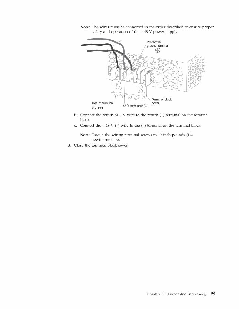
Note: The wires must be connected in the order described to ensure propersafety and operation of the – 48 V power supply.
Protectiveground terminal
Return terminal
0 V ( )+
Terminal blockcover
-48 V terminals ( )--
b. Connect the return or 0 V wire to the return (+) terminal on the terminalblock.
c. Connect the – 48 V (–) wire to the (–) terminal on the terminal block.
Note: Torque the wiring-terminal screws to 12 inch-pounds (1.4newton-meters).
3. Close the terminal block cover.
Chapter 6. FRU information (service only) 59
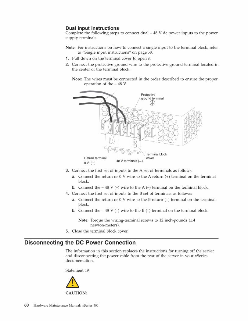
Dual input instructionsComplete the following steps to connect dual – 48 V dc power inputs to the powersupply terminals.
Note: For instructions on how to connect a single input to the terminal block, referto “Single input instructions” on page 58.
1. Pull down on the terminal cover to open it.2. Connect the protective ground wire to the protective ground terminal located in
the center of the terminal block.
Note: The wires must be connected in the order described to ensure the properoperation of the – 48 V.
Protectiveground terminal
Return terminal
0 V ( )+
Terminal blockcover
-48 V terminals ( )--
3. Connect the first set of inputs to the A set of terminals as follows:a. Connect the return or 0 V wire to the A return (+) terminal on the terminal
block.b. Connect the – 48 V (–) wire to the A (–) terminal on the terminal block.
4. Connect the first set of inputs to the B set of terminals as follows:a. Connect the return or 0 V wire to the B return (+) terminal on the terminal
block.b. Connect the – 48 V (–) wire to the B (–) terminal on the terminal block.
Note: Torque the wiring-terminal screws to 12 inch-pounds (1.4newton-meters).
5. Close the terminal block cover.
Disconnecting the DC Power ConnectionThe information in this section replaces the instructions for turning off the serverand disconnecting the power cable from the rear of the server in your xSeriesdocumentation.
Statement 19
CAUTION:
60 Hardware Maintenance Manual: xSeries 300

The power-control button on the device does not turn off the electrical currentsupplied to the device. The device might also have more than one connection to dcpower. To remove all electrical current from the device, ensure that all connectionsto dc power are disconnected at the dc power input terminals.
OFF
Note: Turning off the server refers to the act of disconnecting the server from thepower source.
Complete the following steps to turn off your server and to disconnect the dcpower connection from the power supply.1. Refer to your operating system documentation for the proper procedure to shut
down the operating system.
Note: Each operating system is different. Some will allow an immediate shutdown, while others require an orderly shut-down procedure.
2. Press the power control button on the front of the server. This will put theserver in stand-by mode.
3. Trip the circuit breaker.4. Pull down on the terminal block cover to open it.5. Disconnect all – 48 V wires from the (–) terminals.6. Disconnect all 0 V wires from the return (+) terminals.7. Disconnect the protective ground wire from the protective ground terminal
located in the center or the terminal block.8. Close the terminal block cover.
PCI riser cardTo remove the PCI riser card:
Note: Read“Safety information” on page 75 and “Before you begin” on page 36.1. Power off the server.2. Remove the cover. See “Removing the cover” on page 38.3. Remove any adapters and put them in a safe place.4. Disconnect cables.5. Gently lift up on the card to disconnect it from the system board port.
Chapter 6. FRU information (service only) 61

System board
To remove the system board:
Note: Read“Safety information” on page 75 and “Before you begin” on page 36.1. Power off the server.2. Remove the cover. See “Removing the cover” on page 38.3. Disconnect all cables from the system board.4. Remove the adapter retaining latch (see “Removing a microprocessor” on
page 49).5. Remove the microprocessors. See “Removing a microprocessor” on page 49.6. Remove the memory modules. See “Installing DIMMs” on page 45.7. Remove screws from the system board.8. Remove the four screws from the rear of the server.9. Pull up on the system board to remove from the chassis.
62 Hardware Maintenance Manual: xSeries 300

Chapter 7. Symptom-to-FRU index
This index supports xSeries 300 server. The Symptom-to-FRU lists symptoms,errors, and the possible causes. The most likely cause is listed first. Use thisSymptom-to-FRU index to help you decide which FRUs to have available whenservicing the computer.
The POST BIOS displays POST error codes and messages on the screen.
Beep symptomsCurrently there are two kinds of beep codes in BIOS. This code indicates that avideo error has occurred and the BIOS cannot initialize the video screen to displayany additional information. This beep code consists of a single long beep followedby two short beeps. The other code indicates that your DRAM error has occurred.This beep code consists of a single long repeating beep.
No beep symptoms
No Beep Symptom FRU/Action
No beep and the systemoperates correctly.
1. Check speaker cables
2. Speaker
3. System board
No Beeps occur aftersuccessfully completingPOST
1. Check speaker connections
2. Speaker
3. System board
No ac power 1. Check the power cord.
2. Power supply.
No beep and no video 1. See “Undetermined problems” on page 70
Diagnostic error codes
Note: In the following error codes, if XXX is 000, 195, or 197,do not replace a FRU.The description for these error codes are:
000 The test passed.
195 The Esc key was pressed to abort the test.
197 This is a warning error and may not indicate a hardware failure.
For all error codes, replace/follow the FRU/Action indicated.
Error Code/Symptom FRU/Action
001-XXX-000
(Failed core tests)
1. System Board
© Copyright IBM Corp. 2000 63

Error Code/Symptom FRU/Action
001-XXX-001
(Failed core tests)
1. System Board
001-250-000
(Failed System Board ECC)
1. System Board
001-250-001
(Failed System Board ECC)
1. System Board
005-XXX-000
(Failed Video test)
1. Video Adapter (if installed)
2. System Board
011-XXX-000
(Failed COM1 Serial Porttest)
1. System Board
011-XXX-001
(Failed COM2 Serial Porttest)
1. System Board
014-XXX-000
(Failed Parallel Port test)
1. System Board
015-XXX-001
(USB interface not found,board damaged)
1. System Board
015-XXX-015
(Failed USB ExternalLoopback test)
1. Make sure parallel port is not disabled
2. Re-run USB External Loopback test
3. System Board
015-XXX-198
(USB device connectedduring USB test)
1. Remove USB devices from USB1 and USB2
2. Re-run test
3. System Board
020-XXX-000
(Failed PCI Interface test)
1. System Board
030-XXX-000
(Failed Internal SCSI interfacetest)
1. System Board
030-XXX-00N
(Failed SCSI test on PCI slotN. Check system error logbefore replacing a FRU.)
1. Adapter in Slot N
035-XXX-099 1. No adapters were found.
2. If adapter is installed re-check connection.
64 Hardware Maintenance Manual: xSeries 300

Error Code/Symptom FRU/Action
035-XXX-S99
(Failed RAID test on PCI slotS. S = number of failing PCIslot. Check System Error Logbefore replacing a FRU.)
1. Adapter
2. SCSI Backplane
3. Cable
035-XXX-SNN
(Check System Error Logbefore replacing a FRU. S =number of failing PCI slot;NN = SCSI ID of failing fixeddisk.)
1. Fixed Disk with SCSI ID NN on RAID adapter in PCI slot S.
035-253-S99
(RAID adapter initializationfailure)
1. ServeRAID Adapter in slot S is not configured properly. Obtain the basic andextended configuration status and refer to the ServeRAID Hardware MaintenanceManual for more information.
2. Cable
3. Adapter
075-XXX-000
(Failed Power Supply test)
1. Power Supply
089-XXX-001
(Failed Microprocessor test)
1. Microprocessor
180-XXX-003
(Failed System Board LEDtest)
1. System Board
201-XXX-0NN
(Failed Memory test) NN =DIMM location.
1. DIMM Location J1-J4
2. Memory card
201-XXX-999
(Multiple DIMM failure, seeerror text.)
1. See error text for failing DIMMs
202-XXX-001
(Failed System Cache test)
1. Microprocessor CPU 1
206-XXX-000
(Failed Diskette Drive test)
1. Cable
2. Diskette Drive
3. System Board
215-XXX-000
(Failed IDE CD-ROM test)
1. CD-ROM Drive Cables
2. CD-ROM Drive
3. System Board
217-XXX-000
(Failed BIOS Fixed Disk test)Note: If RAID is configured,the fixed disk number refersto the RAID logical array.
1. Fixed Disk 1
Chapter 7. Symptom-to-FRU index 65

Error Code/Symptom FRU/Action
217-XXX-001
(Failed BIOS Fixed Disk test)Note: If RAID is configured,the fixed disk number refersto the RAID logical array.
1. Fixed Disk 2
217-XXX-002
(Failed BIOS Fixed Disk test)Note: If RAID is configured,the fixed disk number refersto the RAID logical array.
1. Fixed Disk 3
264-XXX-0NN
(NN = SCSI ID of failingTape Drive)
1. Tape Cartridge, if user executed the Read/Write Tape Drive test (XXX = 256)
2. SCSI or power cable connected to the tape drive with SCSI ID NN
3. Tape drive with SCSI ID NN – refer to Help and Service Information appendix oftape drive’s User Guide.
4. I/O Legacy Board or SCSI Controller – run SCSI Controller diagnostic todetermine of SCSI bus is functioning properly.
264-XXX-999
(Errors on multiple tapedrives, see error text for moreinfo)
1. See error messages/text in the PC Doctor error log for detailed information oneach individual tape drive error.
301-XXX-000
(Failed Keyboard test)
1. Keyboard
405-XXX-000
(Failed Ethernet test oncontroller on the SystemBoard)
1. Verify that Ethernet is not disabled in BIOS.
2. System Board
405-XXX-00N
(Failed Ethernet test onadapter in PCI slot N)
1. Adapter in PCI slot N.
2. System Board
415-XXX-000
(Failed Modem test)
1. Cable
2. Modem
3. System Board
Error symptoms
General FRU/Action
CD is not working properly. 1. Clean the CD.
2. Run CD-ROM diagnostics.
3. CD-ROM Drive
CD-ROM drive tray is notworking.
(The server must bepowered-on.)
1. Insert the end of a paper clip into the manual tray-release opening.
2. Run CD-ROM diagnostics.
3. CD-ROM Drive
66 Hardware Maintenance Manual: xSeries 300

General FRU/Action
CD-ROM drive is notrecognized.
1. Run Configuration/Setup, enable primary IDE channel.
2. Check cables and jumpers.
3. Check for correct device driver.
4. Run CD-ROM diagnostics.
5. CD-ROM drive
6. System Board
Power switch does not work. 1. Verify that switch number 5 of switch block is Off.
2. Power Switch Assembly
3. System Board
CD-ROM drive cable is notplugged in.
1. Make sure CD-ROM drive cable is plugged in.
Diskette drive in-use lightstays on, or the systembypasses the diskette drive,or the diskette drive doesnot work.
1. If there is a diskette in the drive, verify that:a. The diskette drive is enabled in the Configuration/Setup utility program.b. The diskette is good and not damaged. (Try another diskette if you have one.)c. The diskette is inserted correctly in the drive.d. The diskette contains the necessary files to start the server.e. The software program is OK.f. Cable is installed correctly (proper orientation)
2. Run Diskette Drive Diagnostics.
3. Cable
4. Diskette Drive
5. System Board
Drives not recognized byFixed Disk diagnostic. e.g.there are 6 drives, but thefixed-disk test only shows 3
1. Remove the first drive that doesn’t show up and rerun the Fixed Diskdiagnostic. If the remaining drives then show up, replace the drive youremoved.
Hang during Fixed Diskdiagnostic
1. Remove the hard file being tested at the time of the hang. Rerun thediagnostic. If successful, replace the drive you removed.
Monitor problems (general).
Some IBM monitors havetheir own self-tests. If yoususpect a problem with themonitor, refer to theinformation that comes withthe monitor for adjusting andtesting instructions.
1. Monitor
2. Run Video Diagnostics. If diagnostics pass, the problem may be a video driver.
3. Display Adapter / System Board
System Error and DIMM XLED on
1. Replace DIMM X
System Error and CPU XLED on
1. Replace CPU X
System is shut down withno apparent cause
1. Visually check the system fans for operation.
Chapter 7. Symptom-to-FRU index 67

Setup Action
Setup and Installation CDwon’t start.
v Be sure the server is supported; all eServers with a startable (bootable) CD-ROMdrive are supported.
v If the startup (boot) sequence settings have been altered, be sure the CD-ROM isfirst in the boot sequence.
v If more than one CD-ROM drive is installed, be sure that only one drive is set asthe primary drive. Start the CD from the primary drive.
ServeRAID program cannotview all installed drives - or -cannot install NOS.
v Be sure there are no duplicate SCSI IDs or IRQ assignments.v Be sure that the hard disk drive is connected properly.
The Operating SystemInstallation programcontinuously loops.
Free up more space on the hard disk.
ServerGuide won’t start yourNOS CD.
Be sure the NOS CD you have is supported by ServerGuide. See the Setup andInstallation CD label for a list of NOS versions supported.
Can’t install NOS - option isgrayed out.
Either there is no logical drive defined (ServeRAID systems) or the ServerGuidesystem partition is not present. Run the setup and configuration program.
TechConnect CD Action
Can’t start TechConnect CD. Be sure you’re starting the CD on a system with Microsoft Windows installed.
Can’t view publications fromTechConnect CD, or text isunreadable.
Be sure you have the Adobe reader installed (available from the TechConnect CD).
Diskette Factory CD Action
Get “time out” or “Unknownhost” errors
Be sure you have access to the Internet through FTP directly.
68 Hardware Maintenance Manual: xSeries 300

POST error codes
Error Code/Symptom FRU/Action
CMOS battery has failed Cause: CMOS battery is no longer functional. Action: Replace CMOS battery.
CMOS checksum error Cause: Checksum of COMS is incorrect. This can indicate that CMOS has becomecorrupt. This error may have been caused by a weak battery. Action: Check thebattery and replace if necessary.
Disk boot failure, insertsystem disk and press enter
Cause: No boot device was found. This could mean that either a boot drive was notdetected or the drive does not contain proper system boot files. Action: Insert asystem disk into drive A: and press <Enter>. Make sure the controller is insertedcorrectly and all cables are properly attached. Also be sure the disk is formatted as aboot device. Then reboot the system.
Diskette drives or typesmismatch error
Cause: Type of diskette drive installed in the system is different from the CMOSdefinition. Action: Run Setup to reconfigure the drive type correctly.
Display switch is setincorrectly
Cause: Display switch on the motherboard can be set to either monochrome or color.This indicates the switch is set to a different setting than indicated in setup. Action:Determine which setting is correct, and then either turn off the system and changethe jumper, or enter setup and change the video selection.
Display type has changedsince last boot
Cause: Since last powering off the system, the display adapter has been changed.Action: Configure the system for the new display type.
EISA configurationchecksum error
Cause: The EISA non-volatile RAm checksum is incorrect or can not correctly readthe EIS slot. This can indicate either the EISA non-volatile memory has becomecorrupt or the slot has been configured incorrectly. Ensure the card is installed firmlyin the slot. Action: Run EISA configuration utility.
EISA configuration is notcomplete
Cause: The slot configuration information stored in the EISA non-volatile memory isincomplete. Action: Run EISA configuration utility.
Error encounteredinitializing hard drive
Cause: Hard drive cannot be initialized. Action: Ensure adapter is installed correctlyand all cables are correctly and firmly attached. Ensure the correct hard drive type isselected in setup.
Error initializing hard diskcontroller
Cause: Cannot initialize controller. Action: Ensure the cable is correctly and firmlyinstalled in the bus. Ensure the correct hard drive type is selected in setup. Check tosee if any jumper needs to be set correctly on the hard drive.
Floppy disk cntrlr error orno cntrlr present
Cause: Can not find or initialize the floppy disk controller. Action: Make sure thecontroller is installed correctly and firmly. If there are no floppy drives installed, besure the diskette drive selection in setup is set to None.
Invalid EISA configuration Cause: The non-volatile memory containing EIS configuration information wasprogrammed incorrectly or has become corrupt. Action: Re-run EIS configurationutility to correctly program the memory.
Keyboard error or nokeyboard present
Cause: Cannot initialize the keyboard. Action: Make sure the keyboard is attachedcorrectly and no keys are being pressed during the boot. If configuring the systemwithout a keyboard, set the error halt condition in setup to HALT ON ALL BUTKEYBOARD. This will cause the BIOS to ignore the missing keyboard and continuethe boot.
Memory address error at ... Cause: Memory address error at specific location. Action: Use this location alongwith the memory map for the system to find and replace the failed memory DIMM.
Memory parity error at ... Cause: Memory parity error at a specific location. Action: Use this location alongwith the memory map for the system to find and replace the failed memory DIMM.
Memory size has changedsince last boot
Cause: Memory has been added or removed since the last boot. Action: In EISAmode, use configuration utility to reconfigure the memory. In ISA mode, enter setupand enter the new memory size in the memory fields.
Memory verify error at ... Cause: Error verifying a value already written to memory. Action: Use the locationalong with your system memory map to locate and replace the defective DIMM.
Chapter 7. Symptom-to-FRU index 69

Error Code/Symptom FRU/Action
Offending address notfound
Cause: This message is used in conjunction with the I/O channel check and RAMPARITY error message when the segment that has caused the problem cannot beisolated.
Press a key to reboot Cause: An error has occurred that requires a reboot. Action: Press any key.
Press F1 to disable NMI, F2to reboot
Cause: BIOS detected a non-maskable interrupt condition during boot. Action: PressF1 to disable NMI or F2 to reboot the system with NMI enabled.
RAM parity error - checkingfor segment...
Cause: Parity error in Random Access Memory.
Should be empty but EISboard found
Cause: A valid board ID was found in a slot that was configured as having no boardID. Action: Run EISA configuration utility.
ServeRAIDFor ServeRAID error codes and procedures, refer to the Hardware MaintenanceManual for the particular RAID adapter in the system being serviced.
Undetermined problemsYou are here because the diagnostic tests did not identify the failure, the DevicesList is incorrect, or the system is inoperative.
Note: A corrupt CMOS can cause undetermined problems.
If power problems are suspected:1. Power-off the computer.2. Be sure the system is cabled correctly.3. Remove or disconnect the following (one at a time) until you find the failure
(power-on the computer and reconfigure each time).v Any external devicesv Surge suppressor device (on the computer)v Modem, printer, mouse, or non-IBM devicesv Each adapterv Drivesv Memory Modules (Minimum requirement = one 128 MB DIMM)
Note: Minimum operating requirements are:a. 1 Power Supplyb. System Boardc. 1 Microprocessord. 1 Terminator Card in Slot 2e. 1 Memory Module (minimum of 1 DIMM in slot labeled DIMM 1)
4. Power-on the computer. If the problem remains, suspect the following FRUs inthe order listed:
Power SupplySystem Board
Notes:
1. If the problem goes away when you remove an adapter from the system, andreplacing that adapter does not correct the problem, suspect the system board,then the power supply.
2. If you suspect a networking problem and all the system tests pass, suspect anetwork cabling problem external to the system.
70 Hardware Maintenance Manual: xSeries 300

Chapter 8. Parts listing
The xSeries 300 Parts Listing supports the following models: 21x, 22x, 23x, 2Ax,51x, 52x, 53x, 81x, 82x, 83x
1
2
3
4
5
6
7
8
9
1011
12
13
14
15
16
17
© Copyright IBM Corp. 2000 71

Index System Part (Model Number) FRU Number1 Bracket/Baffle (All models) 00N69932 Heat Sink/Clip Assembly (All models) 00N69873 Terminator Card (All models) 09N80074 Fan with Connector (All models) 00N69915 3.5 Floppy Disk Drive, 12.7MM (All models) 36L86456 Floppy Disk Drive/CD Bracket (All models) 00N69997 CD-ROM drive, 24X LG (All models) 09N08838 Power Supply, 200 Watt, -48V (Model 2Ax) 24P68438 Power Supply, 200 Watt (All models not previously listed) 00N77119 Blank Hard Disk Drive (All models) 06P6245
10 Bezel, Right Front (All models) 24P065111 Switch card (All models) 09N722512 Chassis (All models) 24P065213 Planar (All models) 32P840114 Slim Adapter Board (All models) 19K135115 Coppermine 100/800 MHz Processor (Models 21x, 22x 23x,
2Ax)25P4418
15 Celeron 100/950-128 MHz Process (Models 51x, 52x, 53x) 49P289015 1000/133 MHz Processor (Models 81x, 82x, 83x) 25P278216 PCI Riser Card (All models) 24P064617 Memory, 256MB/133MHz ECC (All models) 33L314517 Memory, 256MB/133MHz 3VED (Models 81x, 82x, 83x) 33L308417 Memory, 128MB/133MHz ECC (All models) (optional) 33L314317 Memory, 128MB/133MHz 3VED (Models 21x, 22x, 23x, 2Ax,
51x, 52x, 53x)33L3082
Hardware Kit (All models) 00N6997Rail Assembly (All models) 32P9216External Interface Adapter Bracket (All models) 00N6995Cable, CD-Power (All models) 00N6989Cable, FDD Signal (All models) 00N6998Battery, 3.0 Volt (8590) (All models) 33F8354Line Cord (All models) 36L8886Heatsink clip (All models) 06P6240Fan Blank (All models) 24P0637Bezel, Left Front (All models) 24P0641Service Label (All models) 24P0649Cable, SCSI 68-Pin (All models) 06P6237Cable, HDD 4-Pin Power (All models) 24P0622Cable, IDE Signal (All models) 24P0657HDD, 18.2 SCSI (Models 23x, 2Ax, 53x, 83x) 19K1485HDD, 20.0 GB ATA-100 (Models 22x, 2Ax, 52x, 82x) 19K1565
Keyboards
Keyboard FRU No.US English 37L2551French Canadian 37L2552LA Spanish 37L2553Arabic 37L2555Belgium/French 37L2556Belgium/UK 37L2557Bulgarian 37L2558Czech 37L2559
72 Hardware Maintenance Manual: xSeries 300

Keyboard FRU No.Danish 37L2560Dutch 37L2561French 37L2562German 37L2563Greek 37L2564Hebrew 37L2565Hungarian 37L2566Korean 02K0901Iceland 37L2567Italy 37L2568Norwegian 37L2569Polish 37L2570Portuguese 37L2571Romanian 37L2572Russian 37L2573Serbian/Cyrillic 37L2574Slavic 37L2575Spanish 37L2576Swedish/Finn 37L2577Swiss, F/G 37L2578Turkish 37L2579Turkish 37L2580UK English 37L2581Yugosl/Lat 37L2582US English-EMEA 37L2583Chinese/US 37L2585Thailand 37L2587French Canadian 37L0913
Power cords
Power cord FRU No.China (PRC) 01K9851Japan 01K9853Thailand 12J5120Israel 12J5122Bangladesh, Burma, India, Pakistan, South Africa, Sri Lanka 12J5124Chile, Ethiopia, Italy, Libya, Somalia 12J5126Argentina, Australia, New Zealand, Papua New Guinea, Paraguay,Uruguay, Western Samoa
12J5128
Antigua, Bahrain, Brunei, Channel Islands, Cyprus, Dubai, Fiji,Ghana, China (Hong Kong S.A.R.), Iraq, Ireland, Kenya, Kuwait,Malawi, Malaysia, Malta, Nepal, Nigeria, Polynesia, Qatar, SierraLeone, Singapore, Tanzania, Uganda, United Kingdom, Yemen,Zambia
12J5987
Afghanistan, Algeria, Andorra, Angola, Austria, Belgium, Benin,Bulgaria, Burkina Faso, Burundi, Cameroon, Central African Rep.,Chad, Czech Republic, Egypt, Finland, France, French Guyana,Germany, Greece, Guinea, Hungary, Iceland, Indonesia, Iran, IvoryCoast, Jordan, Lebanon, Luxembourg, China (Macao S.A.R.),Malagasy, Mali, Martinique, Mauritania, Mauritius, Monaco,Morocco, Mozambique, Netherlands, New Caledonia, Niger,Norway, Poland, Portugal, Romania, Senegal, Slovakia, Spain,Sudan, Sweden, Syria, Togo, Tunisia, Turkey, former USSR,Vietnam, former Yugoslavia, Zaire, Zimbabwe
55H6643
Chapter 8. Parts listing 73

Power cord FRU No.Denmark, Switzerland, Liechtenstein 55H6646Bahamas, Barbados, Bermuda, Bolivia, Brazil, Canada, CaymanIslands, Colombia, Costa Rica, Dominican Republic, Ecuador, ElSalvador, Guatemala, Guyana, Haiti, Honduras, Jamaica, Korea(South), Liberia, Mexico, Netherlands Antilles, Nicaragua, Panama,Peru, Philippines, Saudi Arabia, Suriname, Taiwan, Trinidad (WestIndies), Venezuela
76H4865
United States of America 6952301 (110) 1838574(220) 36L8886(220V/15A)
74 Hardware Maintenance Manual: xSeries 300

Chapter 9. Related service information
Note: The service procedures are designed to help you isolate problems. They arewritten with the assumption that you have model-specific training on allcomputers, or that are familiar with the computers, functions, terminology,and service information provided in this manual.
Safety informationThe following section contains the safety information that you need to be familiarwith before servicing an IBM mobile computer.
General safetyFollow these rules to ensure general safety:v Observe good housekeeping in the area of the machines during and after
maintenance.v When lifting any heavy object:
1. Ensure you can stand safely without slipping.2. Distribute the weight of the object equally between your feet.3. Use a slow lifting force. Never move suddenly or twist when you attempt to
lift.4. Lift by standing or by pushing up with your leg muscles; this action removes
the strain from the muscles in your back. Do not attempt to lift any objects thatweigh more than 16 kg (35 lb) or objects that you think are too heavy for you.
v Do not perform any action that causes hazards to the customer, or that makesthe equipment unsafe.
v Before you start the machine, ensure that other service representatives and thecustomer’s personnel are not in a hazardous position.
v Place removed covers and other parts in a safe place, away from all personnel,while you are servicing the machine.
v Keep your tool case away from walk areas so that other people will not trip overit.
v Do not wear loose clothing that can be trapped in the moving parts of amachine. Ensure that your sleeves are fastened or rolled up above your elbows.If your hair is long, fasten it.
v Insert the ends of your necktie or scarf inside clothing or fasten it with anonconductive clip, approximately 8 centimeters (3 inches) from the end.
v Do not wear jewelry, chains, metal-frame eyeglasses, or metal fasteners for yourclothing.Remember: Metal objects are good electrical conductors.
v Wear safety glasses when you are: hammering, drilling soldering, cutting wire,attaching springs, using solvents, or working in any other conditions that mightbe hazardous to your eyes.
v After service, reinstall all safety shields, guards, labels, and ground wires.Replace any safety device that is worn or defective.
v Reinstall all covers correctly before returning the machine to the customer.
© Copyright IBM Corp. 2000 75

Electrical safety
CAUTION:Electrical current from power, telephone, and communication cables can behazardous. To avoid personal injury or equipment damage, disconnect theattached power cords, telecommunication systems, networks, and modems beforeyou open the server covers, unless instructed otherwise in the installation andconfiguration procedures.
Observe the following rules when working on electrical equipment.
Important: Use only approved tools and test equipment. Some hand tools havehandles covered with a soft material that does not insulate you whenworking with live electrical currents.
Many customers have, near their equipment, rubber floor mats thatcontain small conductive fibers to decrease electrostatic discharges. Donot use this type of mat to protect yourself from electrical shock.
v Find the room emergency power-off (EPO) switch, disconnecting switch, orelectrical outlet. If an electrical accident occurs, you can then operate the switchor unplug the power cord quickly.
v Do not work alone under hazardous conditions or near equipment that hashazardous voltages.
v Disconnect all power before:– Performing a mechanical inspection– Working near power supplies– Removing or installing main units
v Before you start to work on the machine, unplug the power cord. If you cannotunplug it, ask the customer to power-off the wall box that supplies power to themachine and to lock the wall box in the off position.
v If you need to work on a machine that has exposed electrical circuits, observethe following precautions:– Ensure that another person, familiar with the power-off controls, is near you.
Remember: Another person must be there to switch off the power, ifnecessary.
– Use only one hand when working with powered-on electrical equipment;keep the other hand in your pocket or behind your back.Remember: There must be a complete circuit to cause electrical shock. Byobserving the above rule, you may prevent a current from passing throughyour body.
– When using testers, set the controls correctly and use the approved probeleads and accessories for that tester.
– Stand on suitable rubber mats (obtained locally, if necessary) to insulate youfrom grounds such as metal floor strips and machine frames.
76 Hardware Maintenance Manual: xSeries 300

Observe the special safety precautions when you work with very high voltages;these instructions are in the safety sections of maintenance information. Useextreme care when measuring high voltages.
v Regularly inspect and maintain your electrical hand tools for safe operationalcondition.
v Do not use worn or broken tools and testers.v Never assume that power has been disconnected from a circuit. First, check that it
has been powered-off.v Always look carefully for possible hazards in your work area. Examples of these
hazards are moist floors, nongrounded power extension cables, power surges,and missing safety grounds.
v Do not touch live electrical circuits with the reflective surface of a plastic dentalmirror. The surface is conductive; such touching can cause personal injury andmachine damage.
v Do not service the following parts with the power on when they are removedfrom their normal operating places in a machine:– Power supply units– Pumps– Blowers and fans– Motor generators
and similar units. (This practice ensures correct grounding of the units.)v If an electrical accident occurs:
– Use caution; do not become a victim yourself.– Switch off power.– Send another person to get medical aid.
Safety inspection guideThe intent of this inspection guide is to assist you in identifying potentially unsafeconditions on these products. Each machine, as it was designed and built, hadrequired safety items installed to protect users and service personnel from injury.This guide addresses only those items. However, good judgment should be used toidentify potential safety hazards due to attachment of non-IBM features or optionsnot covered by this inspection guide.
If any unsafe conditions are present, you must determine how serious the apparenthazard could be and whether you can continue without first correcting theproblem.
Consider these conditions and the safety hazards they present:v Electrical hazards, especially primary power (primary voltage on the frame can
cause serious or fatal electrical shock).v Explosive hazards, such as a damaged CRT face or bulging capacitorv Mechanical hazards, such as loose or missing hardware
The guide consists of a series of steps presented in a checklist. Begin the checkswith the power off, and the power cord disconnected.
Checklist:1. Check exterior covers for damage (loose, broken, or sharp edges).2. Power-off the computer. Disconnect the power cord.
Chapter 9. Related service information 77

3. Check the power cord for:a. A third-wire ground connector in good condition. Use a meter to measure
third-wire ground continuity for 0.1 ohm or less between the externalground pin and frame ground.
b. The power cord should be the appropriate type as specified in the partslistings.
c. Insulation must not be frayed or worn.4. Remove the cover.5. Check for any obvious non-IBM alterations. Use good judgment as to the safety
of any non-IBM alterations.6. Check inside the unit for any obvious unsafe conditions, such as metal filings,
contamination, water or other liquids, or signs of fire or smoke damage.7. Check for worn, frayed, or pinched cables.8. Check that the power-supply cover fasteners (screws or rivets) have not been
removed or tampered with.
Handling electrostatic discharge-sensitive devicesAny computer part containing transistors or integrated circuits (ICs) should beconsidered sensitive to electrostatic discharge (ESD). ESD damage can occur whenthere is a difference in charge between objects. Protect against ESD damage byequalizing the charge so that the machine, the part, the work mat, and the personhandling the part are all at the same charge.
Notes:
1. Use product-specific ESD procedures when they exceed the requirements notedhere.
2. Make sure that the ESD protective devices you use have been certified (ISO9000) as fully effective.
When handling ESD-sensitive parts:v Keep the parts in protective packages until they are inserted into the product.v Avoid contact with other people.v Wear a grounded wrist strap against your skin to eliminate static on your body.v Prevent the part from touching your clothing. Most clothing is insulative and
retains a charge even when you are wearing a wrist strap.v Use the black side of a grounded work mat to provide a static-free work surface.
The mat is especially useful when handling ESD-sensitive devices.v Select a grounding system, such as those listed below, to provide protection that
meets the specific service requirement.
Note: The use of a grounding system is desirable but not required to protectagainst ESD damage.
– Attach the ESD ground clip to any frame ground, ground braid, or green-wireground.
– Use an ESD common ground or reference point when working on adouble-insulated or battery-operated system. You can use coax orconnector-outside shells on these systems.
– Use the round ground-prong of the ac plug on ac-operated computers.
78 Hardware Maintenance Manual: xSeries 300

Grounding requirementsElectrical grounding of the computer is required for operator safety and correctsystem function. Proper grounding of the electrical outlet can be verified by acertified electrician.
Safety notices (multi-lingual translations)The caution and danger safety notices in this section are provided in the followinglanguages:v Englishv Brazilian/Portuguesev Chinesev Frenchv Germanv Italianv Koreanv Spanish
Important: All caution and danger statements in this IBM documentation beginwith a number. This number is used to cross reference an Englishcaution or danger statement with translated versions of the caution ordanger statement in this section.
For example, if a caution statement begins with a number 1,translations for that caution statement appear in this section understatement 1.
Be sure to read all caution and danger statements before performingany of the instructions.
v Statement 1
DANGER
Electrical current from power, telephone and communication cables is hazardous.
To avoid a shock hazard:
v Do not connect or disconnect any cables or perform installation, maintenance,or reconfiguration of this product during an electrical storm.
v Connect all power cords to a properly wired and grounded electrical outlet.
v Connect to properly wired outlets any equipment that will be attached to thisproduct.
v When possible, use one hand only to connect or disconnect signal cables.
v Never turn on any equipment when there is evidence of fire, water, orstructural damage.
v Disconnect the attached power cords, telecommunications systems, networks,and modems before you open the device covers, unless instructed otherwisein the installation and configuration procedures.
Chapter 9. Related service information 79

v Connect and disconnect cables as described in the following table wheninstalling, moving, or opening covers on this product or attached devices.
To Connect To Disconnect
1. Turn everything OFF.
2. First, attach all cables to devices.
3. Attach signal cables to connectors.
4. Attach power cords to outlet.
5. Turn device ON.
1. Turn everything OFF.
2. First, remove power cords from outlet.
3. Remove signal cables from connectors.
4. Remove all cables from devices.
v Statement 2
CAUTION:When replacing the lithium battery, use only IBM Part Number 33F8354 or anequivalent type battery recommended by the manufacturer. If your system has amodule containing a lithium battery, replace it only with the same module typemade by the same manufacturer. The battery contains lithium and can explode ifnot properly used, handled, or disposed of.
Do not:
v Throw or immerse into water
v Heat to more than 100°C (212°F)
v Repair or disassemble
Dispose of the battery as required by local ordinances or regulations.
v Statement 3
CAUTION:When laser products (such as CD-ROMs, DVD-ROM drives, fiber optic devices,or transmitters) are installed, note the following:
v Do not remove the covers. Removing the covers of the laser product couldresult in exposure to hazardous laser radiation. There are no serviceable partsinside the device.
v Use of controls or adjustments or performance of procedures other than thosespecified herein might result in hazardous radiation exposure.
DANGER: Some laser products contain an embedded Class 3A or Class 3B laserdiode. Note the following:
Laser radiation when open. Do not stare into the beam, do not viewdirectly with optical instruments, and avoid direct exposure to thebeam.
v Statement 4
80 Hardware Maintenance Manual: xSeries 300

≥18 kg (37 lbs) ≥32 kg (70.5 lbs) ≥55 kg (121.2 lbs)
CAUTION:Use safe practices when lifting.
v Statement 5
CAUTION:The power control button on the device and the power switch on the powersupply do not turn off the electrical current supplied to the device. The devicealso might have more than one power cord. To remove all electrical current fromthe device, ensure that all power cords are disconnected from the power source.
1
2
v Statement 10
CAUTION:
Do not place any object weighing more than 82 kg (180 lbs.) on top ofrack-mounted devices.
Chapter 9. Related service information 81

Importante:
Todas as instruções de cuidado e perigo da IBM documentation começam com umnúmero. Este número é utilizado para fazer referência cruzada de uma instruçãode cuidado ou perigo no idioma inglês com as versões traduzidas das instruçõesde cuidado ou perigo encontradas nesta seção.
Por exemplo, se uma instrução de cuidado é iniciada com o número 1, astraduções para aquela instrução de cuidado aparecem nesta seção sob a instrução1.
Certifique-se de ler todas as instruções de cuidado e perigo antes de executarqualquer operação.
Instrução 1
PERIGO
A corrente elétrica proveniente de cabos de alimentação, de telefone e decomunicações é perigosa.
Para evitar risco de choque:v Não conecte ou desconecte cabos e não realize instalação, manutenção ou
reconfiguração deste produto durante uma tempestade com raios.v Conecte todos os cabos de alimentação a tomadas elétricas corretamente
instaladas e aterradas.v Conecte todos os equipamentos ao qual esse produto será conectado a tomadas
corretamente instaladas.v Sempre que possível, utilize apenas uma das mãos para conectar ou desconectar
cabos de sinal.v Nunca ligue qualquer equipamento quando existir evidência de danos por fogo,
água ou na estrutura.v Desconecte cabos de alimentação, sistemas de telecomunicação, redes e modems
antes de abrir as tampas dos dispositivos, a menos que especificado de maneiradiferente nos procedimentos de instalação e configuração.
v Conecte e desconecte cabos conforme descrito na seguinte tabela, ao instalar oumovimentar este produto ou os dispositivos conectados, ou ao abrir suastampas.
Para Conectar: Para Desconectar:
1. DESLIGUE Tudo.
2. Primeiramente, conecte todos os cabosaos dispositivos.
3. Conecte os cabos de sinal aosconectores.
4. Conecte os cabos de alimentação àstomadas.
5. LIGUE os dispositivos.
1. DESLIGUE Tudo.
2. Primeiramente, remova os cabos dealimentação das tomadas.
3. Remova os cabos de sinal dos conectores.
4. Remova todos os cabos dos dispositivos.
82 Hardware Maintenance Manual: xSeries 300

Instrução 2
CUIDADO:
Ao substituir a bateria de lítio, utilize apenas uma bateria IBM, Número de Peça33F8354 ou uma bateria de tipo equivalente, recomendada pelo fabricante. Se o seusistema possui um móídulo com uma bateria de lítio, substitua-o apenas pelomesmo tipo de mídulo, do mesmo fabricante. A bateria contém lítio e podeexplodir se não for utilizada, manuseada e descartada de maneira correta.
Não:v Jogue ou coloque na águav Aqueça a mais de 1006C (2126F)v Conserte nem desmonte
Para descartar a bateria, entre em contato com a área de atendimento a clientesIBM, pelo telefone (011) 889-8986, para obter informações sobre como enviar abateria pelo correio para a IBM.
Instrução 3
PRECAUCIÓN:
Quando produtos a laser (unidades de CD-ROM, unidades de DVD, dispositivosde fibra ítica, transmissores, etc.) estiverem instalados, observe o seguinte:v Não remova as tampas. A remoção das tampas de um produto a laser pode
resultar em exposição prejudicial à radiação de laser. Nenhuma peça localizadano interior do dispositivo pode ser consertada.
v A utilização de controles ou ajustes ou a execução de procedimentos diferentesdos especificados aqui pode resultar em exposição prejudicial à radiação.
PERIGO
Alguns produtos a laser contêm um diodo laser da Classe 3A ou Classe 3Bembutido. Observe o seguinte:
Radiação de laser quando aberto. Não olhe diretamente para o raio a olho nu oucom instrumentos íticos, e evite exposição direta ao raio.
Instrução 4
Chapter 9. Related service information 83

≥18 kg (37 lbs) ≥32 kg (70.5 lbs) ≥55 kg (121.2 lbs)
CUIDADO:
Ao levantar a máquina, faça-o com segurança.
Instrução 5
CUIDADO:
Os botões Liga/Desliga localizados no dispositivo e na fonte de alimentação nãodesligam a corrente elétrica fornecida ao dispositivo. O dispositivo também podeter mais de um cabo de alimentação. Para remover toda a corrente elétrica dodispositivo, assegure que todos os cabos de alimentação estejam desconectados dafonte de energia elétrica.
1
2
CUIDADO:
Instrução 10
CUIDADO:
Não coloque nenhum objeto com peso superior a 82 kg (180 lbs.) sobre dispositivosmontados em rack.
84 Hardware Maintenance Manual: xSeries 300
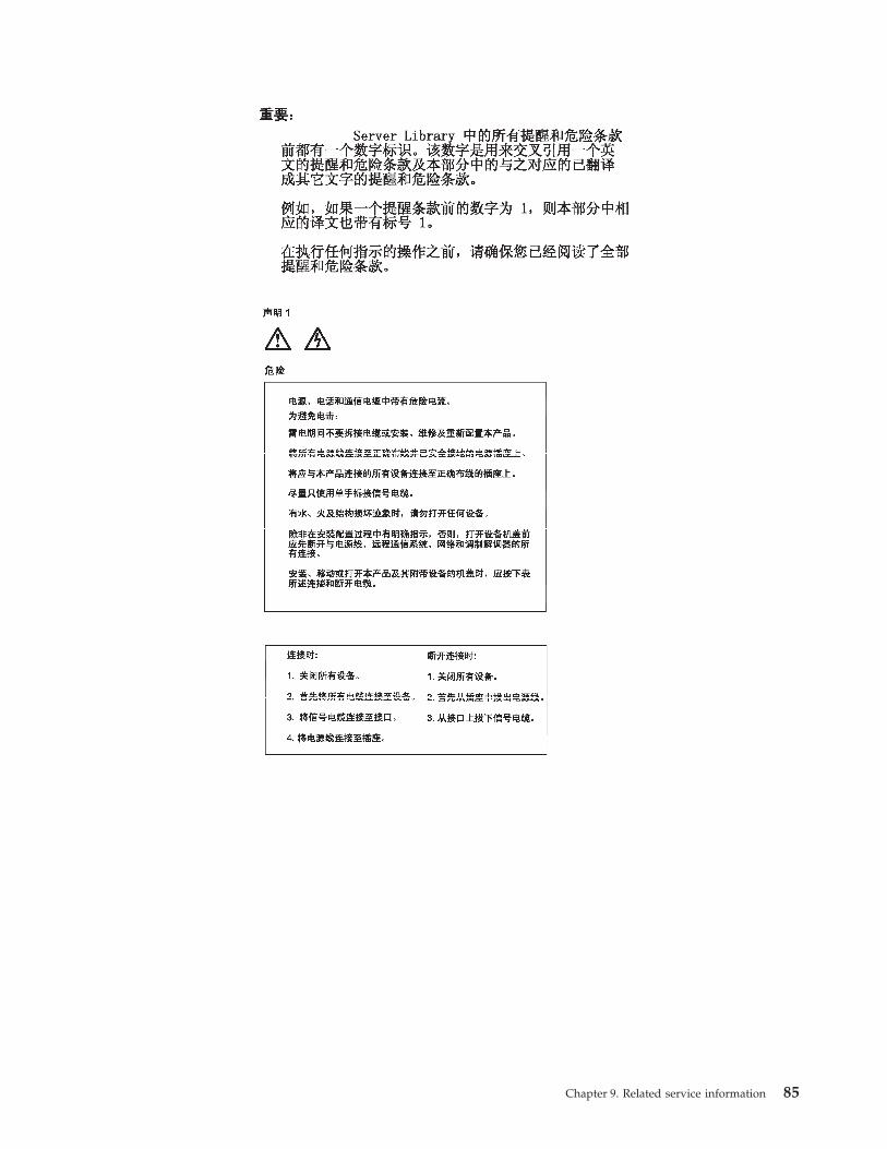
Chapter 9. Related service information 85

86 Hardware Maintenance Manual: xSeries 300
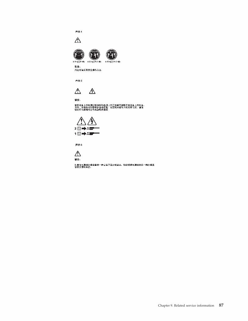
Chapter 9. Related service information 87

88 Hardware Maintenance Manual: xSeries 300

Chapter 9. Related service information 89
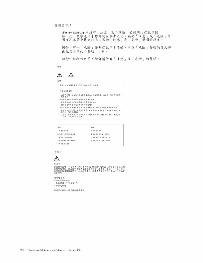
90 Hardware Maintenance Manual: xSeries 300

Chapter 9. Related service information 91

92 Hardware Maintenance Manual: xSeries 300
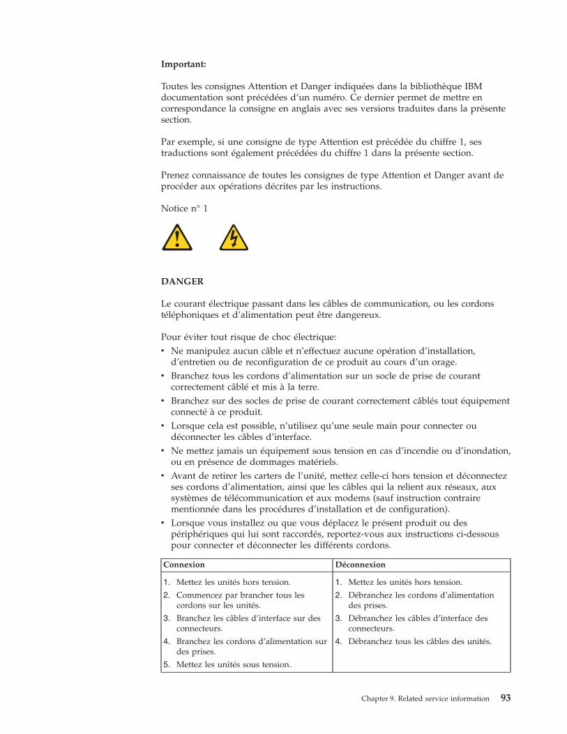
Important:
Toutes les consignes Attention et Danger indiquées dans la bibliothèque IBMdocumentation sont précédées d’un numéro. Ce dernier permet de mettre encorrespondance la consigne en anglais avec ses versions traduites dans la présentesection.
Par exemple, si une consigne de type Attention est précédée du chiffre 1, sestraductions sont également précédées du chiffre 1 dans la présente section.
Prenez connaissance de toutes les consignes de type Attention et Danger avant deprocéder aux opérations décrites par les instructions.
Notice n° 1
DANGER
Le courant électrique passant dans les câbles de communication, ou les cordonstéléphoniques et d’alimentation peut être dangereux.
Pour éviter tout risque de choc électrique:v Ne manipulez aucun câble et n’effectuez aucune opération d’installation,
d’entretien ou de reconfiguration de ce produit au cours d’un orage.v Branchez tous les cordons d’alimentation sur un socle de prise de courant
correctement câblé et mis à la terre.v Branchez sur des socles de prise de courant correctement câblés tout équipement
connecté à ce produit.v Lorsque cela est possible, n’utilisez qu’une seule main pour connecter ou
déconnecter les câbles d’interface.v Ne mettez jamais un équipement sous tension en cas d’incendie ou d’inondation,
ou en présence de dommages matériels.v Avant de retirer les carters de l’unité, mettez celle-ci hors tension et déconnectez
ses cordons d’alimentation, ainsi que les câbles qui la relient aux réseaux, auxsystèmes de télécommunication et aux modems (sauf instruction contrairementionnée dans les procédures d’installation et de configuration).
v Lorsque vous installez ou que vous déplacez le présent produit ou despériphériques qui lui sont raccordés, reportez-vous aux instructions ci-dessouspour connecter et déconnecter les différents cordons.
Connexion Déconnexion
1. Mettez les unités hors tension.
2. Commencez par brancher tous lescordons sur les unités.
3. Branchez les câbles d’interface sur desconnecteurs.
4. Branchez les cordons d’alimentation surdes prises.
5. Mettez les unités sous tension.
1. Mettez les unités hors tension.
2. Débranchez les cordons d’alimentationdes prises.
3. Débranchez les câbles d’interface desconnecteurs.
4. Débranchez tous les câbles des unités.
Chapter 9. Related service information 93

Notice n° 2
ATTENTION:
Remplacez la pile au lithium usagée par une pile de référence identiqueexclusivement - voir la référence IBM - ou par une pile équivalenterecommandée par le fabricant. Si votre système est doté d’un module contenantune pile au lithium, vous devez le remplacer uniquement par un moduleidentique, produit par le même fabricant. La pile contient du lithium et présentedonc un risque d’explosion en cas de mauvaise manipulation ou utilisation.
v Ne la jetez pas à l’eau.
v Ne l’exposez pas à une température supérieure à 100 °C.
v Ne cherchez pas à la réparer ou à la démonter.
Pour la mise au rebut, reportez-vous à la réglementation en vigueur.
Notice n° 3
ATTENTION:
Si des produits laser sont installés (tels que des unités de CD-ROM ou de DVD,des périphériques contenant des fibres optiques ou des émetteurs-récepteurs),prenez connaissance des informations suivantes:
v N’ouvrez pas ces produits pour éviter une exposition directe au rayon laser.Vous ne pouvez effectuer aucune opération de maintenance à l’intérieur.
v Pour éviter tout risque d’exposition au rayon laser, respectez les consignes deréglage et d’utilisation des commandes, ainsi que les procédures décrites dansle présent document.
DANGER
Certains produits laser contiennent une diode laser de classe 3A ou 3B. Prenezconnaissance des informations suivantes:
Rayonnement laser lorsque le carter est ouvert. évitez de regarder fixement lefaisceau ou de l’observer à l’aide d’instruments optiques. évitez une expositiondirecte au rayon.
Notice n° 4
94 Hardware Maintenance Manual: xSeries 300

≥18 kg (37 lbs) ≥32 kg (70.5 lbs) ≥55 kg (121.2 lbs)
ATTENTION:
Faites-vous aider pour soulever ce produit.
Notice n° 5
ATTENTION:
Le bouton de mise sous tension/hors tension de l’unité et l’interrupteurd’alimentation du bloc d’alimentation ne coupent pas l’arrivée de courantélectrique à l’intérieur de la machine. Il se peut que votre unité dispose deplusieurs cordons d’alimentation. Pour isoler totalement l’unité du réseauélectrique, débranchez tous les cordons d’alimentation des socles de prise decourant.
1
2
Notice n° 10
ATTENTION:
Ne posez pas d’objet dont le poids dépasse 82 kg sur les unités montées enarmoire.
Chapter 9. Related service information 95

Wichtig:
Alle Sicherheitshinweise in dieser IBM documentation beginnen mit einerNummer. Diese Nummer verweist auf einen englischen Sicherheitshinweis mit denübersetzten Versionen dieses Hinweises in diesem Abschnitt.
Wenn z. B. ein Sicherheitshinweis mit der Nummer 1 beginnt, so erscheint dieübersetzung für diesen Sicherheitshinweis in diesem Abschnitt unter dem Hinweis1.
Lesen Sie alle Sicherheitshinweise, bevor Sie eine Anweisung ausführen.
Hinweis 1
VORSICHT
Elektrische Spannungen von Netz-, Telefon- und Datenübertragungsleitungen sindgefährlich.
Aus Sicherheitsgründen:v Bei Gewitter an diesem Gerät keine Kabel anschließen oder lösen. Ferner keine
Installations-, Wartungs- oder Rekonfigurationsarbeiten durchführen.v Gerät nur an eine Schutzkontaktsteckdose mit ordnungsgemäß geerdetem
Schutzkontakt anschließen.v Alle angeschlossenen Geräte ebenfalls an Schutzkontaktsteckdosen mit
ordnungsgemäß geerdetem Schutzkontakt anschließen.v Signalkabel möglichst einhändig anschließen oder lösen.v Keine Geräte einschalten, wenn die Gefahr einer Beschädigung durch Feuer,
Wasser oder andere Einflüsse besteht.v Die Verbindung zu den angeschlossenen Netzkabeln,
Telekommunikationssystemen, Netzwerken und Modems ist vor dem öffnen desGehäuses zu unterbrechen. Es sei denn, dies ist in den zugehörigen Installations-und Konfigurationsprozeduren anders angegeben.
v Nur nach den nachfolgend aufgeführten Anweisungen arbeiten, die fürInstallation, Transport oder öffnen von Gehäusen von Personal Computern oderangeschlossenen Einheiten gelten.
Kabel anschlieβen: Kabel lösen:
1. Alle Geräte ausschalten und Netzsteckerziehen.
2. Zuerst alle Kabel an Einheitenanschließen.
3. Signalkabel an Anschlußbuchsenanschließen.
4. Netzstecker an Steckdose anschließen.
5. Gerät einschalten.
1. Alle Geräte ausschalten.
2. Zuerst Netzstecker von Steckdose lösen.
3. Signalkabel von Anschlußbuchsen lösen.
4. Alle Kabel von Einheiten lösen.
96 Hardware Maintenance Manual: xSeries 300
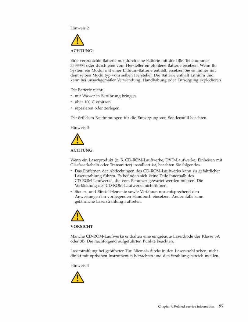
Hinweis 2
ACHTUNG:
Eine verbrauchte Batterie nur durch eine Batterie mit der IBM Teilenummer33F8354 oder durch eine vom Hersteller empfohlene Batterie ersetzen. Wenn IhrSystem ein Modul mit einer Lithium-Batterie enthält, ersetzen Sie es immer mitdem selben Modultyp vom selben Hersteller. Die Batterie enthält Lithium undkann bei unsachgemäßer Verwendung, Handhabung oder Entsorgung explodieren.
Die Batterie nicht:v mit Wasser in Berührung bringen.v über 100 C erhitzen.v reparieren oder zerlegen.
Die örtlichen Bestimmungen für die Entsorgung von Sondermüll beachten.
Hinweis 3
ACHTUNG:
Wenn ein Laserprodukt (z. B. CD-ROM-Laufwerke, DVD-Laufwerke, Einheiten mitGlasfaserkabeln oder Transmitter) installiert ist, beachten Sie folgendes.v Das Entfernen der Abdeckungen des CD-ROM-Laufwerks kann zu gefährlicher
Laserstrahlung führen. Es befinden sich keine Teile innerhalb desCD-ROM-Laufwerks, die vom Benutzer gewartet werden müssen. DieVerkleidung des CD-ROM-Laufwerks nicht öffnen.
v Steuer- und Einstellelemente sowie Verfahren nur entsprechend denAnweisungen im vorliegenden Handbuch einsetzen. Andernfalls kanngefährliche Laserstrahlung auftreten.
VORSICHT
Manche CD-ROM-Laufwerke enthalten eine eingebaute Laserdiode der Klasse 3Aoder 3B. Die nachfolgend aufgeführten Punkte beachten.
Laserstrahlung bei geöffneter Tür. Niemals direkt in den Laserstrahl sehen, nichtdirekt mit optischen Instrumenten betrachten und den Strahlungsbereich meiden.
Hinweis 4
Chapter 9. Related service information 97

≥18 kg ≥32 kg ≥55 kg
ACHTUNG:
Beim Anheben der Maschine die vorgeschriebenen Sicherheitsbestimmungenbeachten.
Hinweis 5
ACHTUNG:
Mit dem Betriebsspannungsschalter an der Vorderseite des Servers und demBetriebsspannungsschalter am Netzteil wird die Stromversorgung für den Servernicht unterbrochen. Der Server könnte auch mehr als ein Netzkabel aufweisen. Umdie gesamte Stromversorgung des Servers auszuschalten, muß sichergestelltwerden, daß alle Netzkabel aus den Netzsteckdosen herausgezogen wurden.
1
2
Hinweis 10
ACHTUNG:
Keine Gegenstände, die mehr als 82 kg wiegen, auf Rack-Einheiten ablegen.
98 Hardware Maintenance Manual: xSeries 300

Importante:
Tutti gli avvisi di attenzione e di pericolo riportati nella pubblicazione IBMdocumentation iniziano con un numero. Questo numero viene utilizzato perconfrontare avvisi di attenzione o di pericolo in inglese con le versioni tradotteriportate in questa sezione.
Ad esempio, se un avviso di attenzione inizia con il numero 1, la relativa versionetradotta è presente in questa sezione con la stessa numerazione.
Prima di eseguire una qualsiasi istruzione, accertarsi di leggere tutti gli avvisi diattenzione e di pericolo.
Avviso 1
PERICOLO
La corrente elettrica circolante nei cavi di alimentazione, del telefono e di segnale èpericolosa.
Per evitare il pericolo di scosse elettriche:v Non collegare o scollegare i cavi, non effettuare l’installazione, la manutenzione
o la riconfigurazione di questo prodotto durante i temporali.v Collegare tutti i cavi di alimentazione ad una presa elettrica correttamente
cablata e munita di terra di sicurezza.v Collegare qualsiasi apparecchiatura collegata a questo prodotto ad una presa
elettrica correttamente cablata e munita di terra di sicurezza.v Quando possibile, collegare o scollegare i cavi di segnale con una sola mano.v Non accendere qualsiasi apparecchiatura in presenza di fuoco, acqua o se sono
presenti danni all’apparecchiatura stessa.v Scollegare i cavi di alimentazione, i sistemi di telecomunicazioni, le reti e i
modem prima di aprire i coperchi delle unità, se non diversamente indicato nelleprocedure di installazione e configurazione.
v Collegare e scollegare i cavi come descritto nella seguente tabella quando sieffettuano l’installazione, la rimozione o l’apertura dei coperchi di questoprodotto o delle unità collegate.
Per collegare: Per scollegare:
1. SPEGNERE tutti i dispositivi.
2. Collegare prima tutti i cavi alle unità.
3. Collegare i cavi di segnale ai connettori.
4. Collegare i cavi di alimentazione alleprese elettriche.
5. ACCENDERE le unità.
1. SPEGNERE tutti i dispositivi.
2. Rimuovere prima i cavi di alimentazionedalle prese elettriche.
3. Rimuovere i cavi di segnale daiconnettori.
4. Rimuovere tutti i cavi dalle unità.
Chapter 9. Related service information 99

Avviso 2
ATTENZIONE:
Quando si sostituisce la batteria al litio, utilizzare solo una batteria IBM connumero parte 33F8354 o batterie dello stesso tipo o di tipo equivalente consigliatedal produttore. Se il sistema di cui si dispone è provvisto di un modulo contenenteuna batteria al litio, sostituire tale batteria solo con un tipo di modulo uguale aquello fornito dal produttore. La batteria contiene litio e può esplodere seutilizzata, maneggiata o smaltita impropriamente.
Evitare di:v Gettarla o immergerla in acquav Riscaldarla ad una temperatura superiore ai 1006Cv Cercare di ripararla o smontarla
Smaltire secondo la normativa in vigore (D.Lgs 22 del 5/2/9) e successivedisposizioni nazionali e locali.
Avviso 3
ATTENZIONE:
Quando si installano prodotti laser come, ad esempio, le unità DVD, CD-ROM, afibre ottiche o trasmettitori, prestare attenzione a quanto segue:v Non rimuovere i coperchi. L’apertura dei coperchi di prodotti laser può
determinare l’esposizione a radiazioni laser pericolose. All’interno delle unitànon vi sono parti su cui effettuare l’assistenza tecnica.
v L’utilizzo di controlli, regolazioni o l’esecuzione di procedure non descritti nelpresente manuale possono provocare l’esposizione a radiazioni pericolose.
PERICOLO
Alcuni prodotti laser contengono all’interno un diodo laser di Classe 3A o Classe3B. Prestare attenzione a quanto segue:
Aprendo l’unità vengono emesse radiazioni laser. Non fissare il fascio, nonguardarlo direttamente con strumenti ottici ed evitare l’esposizione diretta al fascio.
Avviso 4
100 Hardware Maintenance Manual: xSeries 300
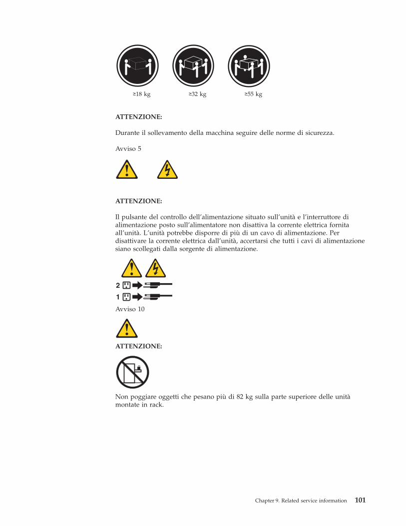
≥18 kg ≥32 kg ≥55 kg
ATTENZIONE:
Durante il sollevamento della macchina seguire delle norme di sicurezza.
Avviso 5
ATTENZIONE:
Il pulsante del controllo dell’alimentazione situato sull’unità e l’interruttore dialimentazione posto sull’alimentatore non disattiva la corrente elettrica fornitaall’unità. L’unità potrebbe disporre di più di un cavo di alimentazione. Perdisattivare la corrente elettrica dall’unità, accertarsi che tutti i cavi di alimentazionesiano scollegati dalla sorgente di alimentazione.
1
2
Avviso 10
ATTENZIONE:
Non poggiare oggetti che pesano più di 82 kg sulla parte superiore delle unitàmontate in rack.
Chapter 9. Related service information 101
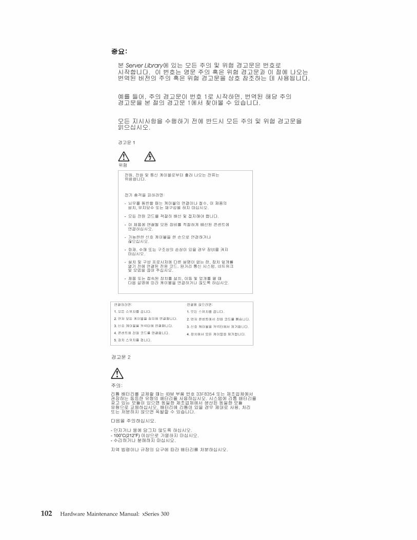
102 Hardware Maintenance Manual: xSeries 300

Chapter 9. Related service information 103

104 Hardware Maintenance Manual: xSeries 300

Importante:
Todas las declaraciones de precauciín de esta IBM documentation empiezan con unnúmero. Dicho número se emplea para establecer una referencia cruzada de unadeclaraciín de precauciín o peligro en inglés con las versiones traducidas que dedichas declaraciones pueden encontrarse en esta secciín.
Por ejemplo, si una declaraciín de peligro empieza con el número 1, lastraducciones de esta declaraciín de precauciín aparecen en esta secciín bajoDeclaraciín 1.
Lea atentamente todas las declaraciones de precauciín y peligro antes de llevar acabo cualquier operaciín.
Declaración 1
PELIGRO
La corriente eléctrica de los cables telefínicos, de alimentaciín y de comunicacioneses perjudicial.
Para evitar una descarga eléctrica:v No conecte ni desconecte ningún cable ni realice las operaciones de instalaciín,
mantenimiento o reconfiguraciín de este producto durante una tormenta.v Conecte cada cable de alimentaciín a una toma de alimentaciín eléctrica con
conexiín a tierra y cableado correctos.v Conecte a tomas de alimentaciín con un cableado correcto cualquier equipo que
vaya a estar conectado a este producto.v Si es posible, utilice una sola mano cuando conecte o desconecte los cables de
sent.al.v No encienda nunca un equipo cuando haya riesgos de incendio, de inundaciín o
de daños estructurales.v Desconecte los cables de alimentaciín, sistemas de telecomunicaciones, redes y
mídems conectados antes de abrir las cubiertas del dispositivo a menos que seindique lo contrario en los procedimientos de instalaciín y configuraciín.
v Conecte y desconecte los cables tal como se describe en la tabla siguiente cuandodesee realizar una operaciín de instalaciín, de traslado o de apertura de lascubiertas para este producto o para los dispositivos conectados.
Para la conexin Para la desconexiín
1. APÁGUELO todo.
2. En primer lugar, conecte los cables a losdispositivos.
3. Conecte los cables de señal a losconectores.
4. Conecte cada cable de alimentaciín a latoma de alimentaciín.
5. ENCIENDA el dispositivo.
1. APÁGUELO todo.
2. En primer lugar, retire cada cable dealimentaciín de la toma de alimentaciín.
3. Retire los cables de señal de losconectores.
4. Retire los cables de los dispositivos.
Chapter 9. Related service information 105

Declaración 2
PRECAUCIÓN:
Cuando desee sustituir la batería de litio, utilice únicamente el número de pieza33F8354 de IBM o cualquier tipo de batería equivalente que recomiende elfabricante. Si el sistema tiene un mídulo que contiene una batería de litio,sustitúyalo únicamente por el mismo tipo de mídulo, que ha de estar creado por elmismo fabricante. La batería contiene litio y puede explotar si el usuario no lautiliza ni la maneja de forma adecuada o si no se desprende de la misma comocorresponde.
No realice las acciones siguientes:v Arrojarla al agua o sumergirlav Calentarla a una temperatura que supere los 1006C (2126F)v Repararla o desmontarla
Despréndase de la batería siguiendo los requisitos que exija el reglamento o lalegislaciín local.
Declaración 3
PRECAUCIÓN:
Cuando instale productos láser (como, por ejemplo, CD-ROM, unidades DVD,dispositivos de fibra íptica o transmisores), tenga en cuenta las advertenciassiguientes:v No retire las cubiertas. Si retira las cubiertas del producto láser, puede quedar
expuesto a radiaciín láser perjudicial. Dentro del dispositivo no existe ningunapieza que requiera mantenimiento.
v El uso de controles o ajustes o la realizaciín de procedimientos que no sean losque se han especificado aquí pueden dar como resultado una exposiciínperjudicial a las radiaciones.
PELIGRO
Algunos productos láser contienen un diodo de láser incorporado de Clase 3A o deClase 3B. Tenga en cuenta la advertencia siguiente.
Cuando se abre, hay radiaciín láser. No mire fijamente el rayo ni lleve a caboningún examen directamente con instrumentos ípticos; evite la exposiciín directa alrayo.
106 Hardware Maintenance Manual: xSeries 300
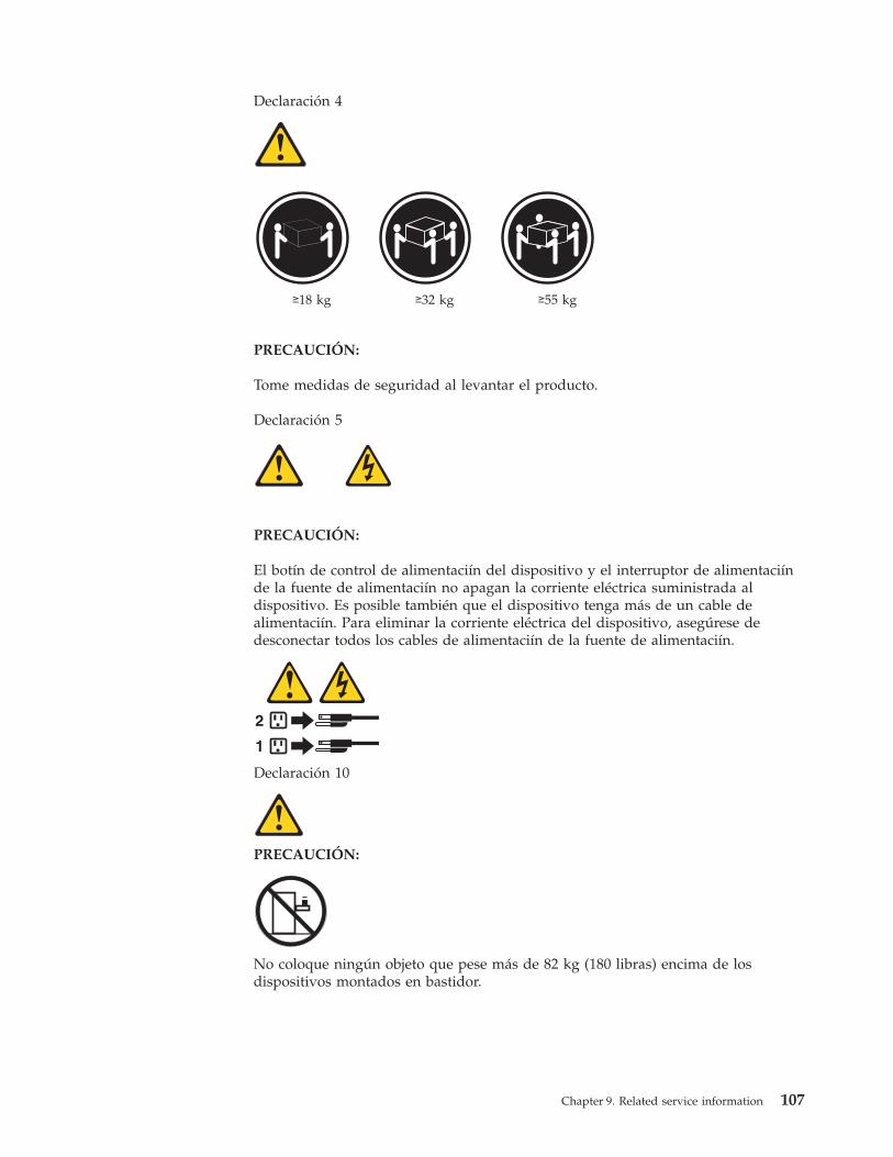
Declaración 4
≥18 kg ≥32 kg ≥55 kg
PRECAUCIÓN:
Tome medidas de seguridad al levantar el producto.
Declaración 5
PRECAUCIÓN:
El botín de control de alimentaciín del dispositivo y el interruptor de alimentaciínde la fuente de alimentaciín no apagan la corriente eléctrica suministrada aldispositivo. Es posible también que el dispositivo tenga más de un cable dealimentaciín. Para eliminar la corriente eléctrica del dispositivo, asegúrese dedesconectar todos los cables de alimentaciín de la fuente de alimentaciín.
1
2
Declaración 10
PRECAUCIÓN:
No coloque ningún objeto que pese más de 82 kg (180 libras) encima de losdispositivos montados en bastidor.
Chapter 9. Related service information 107

Send us your comments!We want to know your opinion about this manual (part number 24P2924). Yourinput will help us to improve our publications.
Please photocopy this survey, complete it, and then fax it to IBM HMM Survey at919-543-8167 (USA).
Name: _________________________________________
Phone number: __________________________________
1. Do you like this manual?
h Yes h No__________________________________________________________________________________
2. What would you like to see added, changed, or deleted in this manual?__________________________________________________________________________________
3. What is your service experience level?
h Less than five years
h More than five years4. Which servers do you service most?
____________________________________________________________________________________________________________________________________________________________________
Thank you for your response!
108 Hardware Maintenance Manual: xSeries 300
Problem determination tipsDue to the variety of hardware and software combinations that can beencountered, use the following information to assist you in problem determination.If possible, have this information available when requesting assistance from ServiceSupport and Engineering functions.v Machine type and modelv Processor or hard disk upgradesv Failure symptom
– Do diagnostics fail?– What, when, where, single, or multiple systems?– Is the failure repeatable?– Has this configuration ever worked?– If it has been working, what changes were made prior to it failing?– Is this the original reported failure?
v Reference/Diagnostics version– Type and version level
v Hardware configuration– Print (print screen) configuration currently in use– BIOS level
v Operating system software– Type and version level
Note: To eliminate confusion, identical systems are considered identical only ifthey:1. Are the exact machine type and models2. Have the same BIOS level3. Have the same adapters/attachments in the same locations4. Have the same address jumpers/terminators/cabling5. Have the same software versions and levels6. Have the same Reference/Diagnostics Diskette (version)7. Have the same configuration options set in the system8. Have the same setup for the operation system control files
Comparing the configuration and software set-up between ″working andnon-working″ systems will often lead to problem resolution.
NoticesReferences in this publication to IBM products, programs, or services do not implythat IBM intends to make these available in all countries in which IBM operates.Any reference to an IBM product, program, or service is not intended to state orimply that only that IBM product, program, or service may be used. Subject toIBM’s valid intellectual property or other legally protectable rights, anyfunctionally equivalent product, program, or service may be used instead of theIBM product, program, or service. The evaluation and verification of operation inconjunction with other products, except those expressly designated by IBM, are theresponsibility of the user.
Chapter 9. Related service information 109

TrademarksThe following items are trademarks of the IBM Corporation in the United States orother countries or both:
HelpCenter® Netfinity ManagerHelpFax® OS/2IBM SystemXtraNetBAY3 ThinkPadNetfinity
The following terms are trademarks of other companies:Notes Lotus Development Corporation
MMX and Pentium are trademarks or registered trademarks of Intel Corporation.
UNIX is a trademark or registered trademark of The Open Group in the UnitedStates and other countries.
Windows NT is a trademark or registered trademark of Microsoft Corporation.
110 Hardware Maintenance Manual: xSeries 300


���
Part Number: 24P2924
(1P) P/N: 24P2924