Alteon OS 20.0 Application Guide -...
472
Application Guide Alteon OS 21.0 Part Number: 24R9742, March 2006 TM Layer 2-7 GbE Switch Module for IBM BladeCenter 4655 Great America Parkway Santa Clara, CA 95054 www.nortelnetworks.com Reference: 215654-D
Transcript of Alteon OS 20.0 Application Guide -...

Application Guide
Alteon OS 21.0
Part Number: 24R9742, March 2006
TM
Layer 2-7 GbE Switch Module for IBM BladeCenter
4655 Great America ParkwaySanta Clara, CA 95054
www.nortelnetworks.comReference: 215654-D
Alteon OS 21.0 Application Guide
224R9742, March 2006
Copyright 2004 Nortel Networks, Inc., 4655 Great America Parkway, Santa Clara, California 95054, USA. All rights reserved. Part Number: 24R9742.
This document is protected by copyright and distributed under licenses restricting its use, copying, distribution, and decompilation. No part of this document may be reproduced in any form by any means without prior written authorization of Nortel Networks, Inc. Documentation is provided “as is” without warranty of any kind, either express or implied, including any kind of implied or express warranty of non-infringement or the implied warranties of merchantability or fitness for a particular purpose.
U.S. Government End Users: This document is provided with a “commercial item” as defined by FAR 2.101 (Oct 1995) and contains “commercial technical data” and “commercial software documentation” as those terms are used in FAR 12.211-12.212 (Oct 1995). Government End Users are authorized to use this documentation only in accordance with those rights and restrictions set forth herein, consistent with FAR 12.211- 12.212 (Oct 1995), DFARS 227.7202 (JUN 1995) and DFARS 252.227-7015 (Nov 1995).
Nortel Networks, Inc. reserves the right to change any products described herein at any time, and without notice. Nortel Networks, Inc. assumes no responsibility or liability arising from the use of products described herein, except as expressly agreed to in writing by Nortel Networks, Inc. The use and purchase of this product does not convey a license under any patent rights, trademark rights, or any other intellectual property rights of Nortel Networks, Inc.
Alteon OS and ACEswitch are trademarks of Nortel Networks, Inc. in the United States and certain other countries. Cisco® and EtherChannel® are registered trademarks of Cisco Systems, Inc. in the United States and certain other countries. Check Point® and FireWall-1® are trademarks or registered trademarks of Check Point Software Technologies Ltd. Any other trademarks appearing in this manual are owned by their respective companies.
Originated in the U.S.A.

Contents
Preface 19Who Should Use This Guide 19What You’ll Find in This Guide 19Typographic Conventions 21How to Get Help 22
Part 1: Basic Switching 23
Chapter 1: Accessing the Switch 25Management module setup 26
Factory-Default vs. MM assigned IP Addresses 26Default Gateway 27Configure management module for switch access 27
Using Telnet 29Connect to the Switch via SSH 30BOOTP Relay Agent 30
Using the Browser-Based Interface 31Configuring BBI Access via HTTP 32Configuring BBI Access via HTTPS 32
Using SNMP 33Using the Console Port 35Securing Access to the Switch 36
Setting Allowable Source IP Address Ranges 37RADIUS Authentication and Authorization 38TACACS+ Authentication 42Secure Shell and Secure Copy 48
24R9742, March 20063

Alteon OS 21.0 Application Guide
End User Access Control 55Considerations for Configuring End User Accounts 55Strong Passwords 55User Access Control Menu 56Listing Current Users 58Logging into an End User Account 58
Chapter 2: VLANs 59Overview 60VLANs and Port VLAN ID Numbers 60
VLAN Numbers 60PVID Numbers 61
VLAN Tagging 62VLAN Topologies and Design Considerations 66
VLAN configuration rules 67Example 1: Multiple VLANs with Tagging Adapters 67
VLANs and Default Gateways 69Segregating VLAN Traffic 69Configuring the Local Network 71Configuring Gateways per VLAN 71
Chapter 3: Ports and Trunking 75Overview 76
Statistical Load Distribution 77Built-In Fault Tolerance 77Before you configure static trunks 77Trunk group configuration rules 78
Port Trunking Example 79Configurable Trunk Hash Algorithm 81Link Aggregation Control Protocol 82
Configuring LACP 84
Chapter 4: Spanning Tree Group 85Overview 86Bridge Protocol Data Units (BPDUs) 87
Determining the Path for Forwarding BPDUs 87Spanning Tree Group configuration guidelines 88
4 : Contents24R9742, March 2006
Alteon OS 21.0 Application Guide
Multiple Spanning Trees 90Default Spanning Tree configuration 90Why Do We Need Multiple Spanning Trees? 91Switch-Centric Spanning Tree Group 91VLAN Participation in Spanning Tree Groups 92Configuring Multiple Spanning Tree Groups 93
Port Fast Forwarding 94Configuring Port Fast Forwarding 94
Fast Uplink Convergence 95Configuration Guidelines 95Configuring Fast Uplink Convergence 95
Part 2: IP Routing 97
Chapter 5: Basic IP Routing 99IP Routing Benefits 100Routing Between IP Subnets 100Example of Subnet Routing 103Defining IP Address Ranges for the Local Route Cache 107Configuring Static Multicast Routes 108Dynamic Host Configuration Protocol 108
DHCP Relay Agent 109DHCP Relay Agent Configuration 110
Chapter 6: Routing Information Protocol 111Distance Vector Protocol 111Stability 111Routing Updates 112
Chapter 7: IGMP Snooping 113Overview 114
FastLeave 115IGMP Filtering 115Static Multicast Router 116IGMP Snooping Configuration Example 117
Chapter 8: Border Gateway Protocol 121Internal Routing Versus External Routing 122
: Contents 524R9742, March 2006

Alteon OS 21.0 Application Guide
Forming BGP Peer Routers 123What is a Route Map? 123
Incoming and Outgoing Route Maps 124Precedence 125Configuration Overview 125
Aggregating Routes 127Redistributing Routes 127BGP Attributes 128
Local Preference Attribute 128Metric (Multi-Exit Discriminator) Attribute 128
Selecting Route Paths in BGP 129BGP Failover Configuration 130Default Redistribution and Route Aggregation Example 133
Chapter 9: OSPF 135OSPF Overview 136
Equal Cost Multipath Routing Support 136Types of OSPF Areas 136Types of OSPF Routing Devices 138Neighbors and Adjacencies 139The Link-State Database 139The Shortest Path First Tree 140Internal Versus External Routing 140
OSPF Implementation in Alteon OS 141Configurable Parameters 141Defining Areas 142Interface Cost 144Electing the Designated Router and Backup 144Summarizing Routes 144Default Routes 145Virtual Links 146Router ID 147Authentication 147Host Routes for Load Balancing 150OSPF Features Not Supported in This Release 151
6 : Contents24R9742, March 2006

Alteon OS 21.0 Application Guide
OSPF Configuration Examples 151Example 1: Simple OSPF Domain 152Example 2: Virtual Links 154Example 3: Summarizing Routes 158Example 4: Host Routes 161Verifying OSPF Configuration 167
Part 3: Application Switching Fundamentals 169
Chapter 10: Server Load Balancing 171Understanding Server Load Balancing 172
Identifying Your Network Needs 172How Server Load Balancing Works 173
Implementing Basic Server Load Balancing 175Network Topology Requirements 176Configuring Server Load Balancing 177Additional Server Load Balancing Options 182
Extending SLB Topologies 190Proxy IP Addresses 190Mapping Ports 193Direct Server Interaction 196Delayed Binding 200
Session Initiation Protocol Server Load Balancing 203SIP Processing on the Switch 203Configuring SIP Server Load Balancing 204
Workload Manager Support 207
Chapter 11: Global Server Load Balancing 209DSSP version 1 vs. version 2 209GSLB Overview 210
Benefits 210How GSLB Works 211
GSLB Enhancements 213GSLB Metrics 213Metric preferences 216Rules 216
: Contents 724R9742, March 2006

Alteon OS 21.0 Application Guide
Configuring Basic GSLB 217Basic GSLB Requirements 218Example GSLB Topology 218
Configuring a Standalone GSLB Domain 231GSLB Topology with a Standalone GSLB Site 231
Configuring GSLB with Rules 235Configuring Time-Based Rules 236Using the Availability Metric in a Rule 238
Configuring GSLB Network Preference 239Configuring GSLB with Proxy IP for Non-HTTP Redirects 242
How Proxy IP Works 244Configuring Proxy IP Addresses 245
GSLB DNS Persistence 246Using Border Gateway Protocol for GSLB 246Verifying GSLB Operation 247
Chapter 12: Filtering 249Overview 250
Filtering Benefits 250Filtering Criteria 250Filtering Actions 252Stacking Filters 252Overlapping Filters 253The Default Filter 253VLAN-based Filtering 255Optimizing Filter Performance 257Filter Logs 257IP Address Ranges 259Cache-Enabled versus Cache-Disabled Filters 259
TCP Rate Limiting 260Configuring TCP Rate Limiting Filters 261
Tunable Hash for Filter Redirection 265Filter-based Security 266Network Address Translation 272
Static NAT 272Dynamic NAT 275FTP Client NAT 277
Matching TCP Flags 279
8 : Contents24R9742, March 2006

Alteon OS 21.0 Application Guide
Matching ICMP Message Types 284
Chapter 13: Application Redirection 287Overview 288
Cache Redirection Environment 288Additional Application Redirection Options 289
IP Proxy Addresses for NAT 295Excluding Noncacheable Sites 297
Chapter 14: Health Checking 299Real Server Health Checks 301Link Health Checks 302
Configuring the Switch for Link Health Checks 302TCP Health Checks 303ICMP Health Checks 303Script-Based Health Checks 304
Configuring the Switch for Script-Based Health Checks 304Script Format 305Scripting Guidelines 306Script Configuration Examples 306
Application-Specific Health Checks 308HTTP Health Checks 309UDP-Based DNS Health Checks 311FTP Server Health Checks 312POP3 Server Health Checks 313SMTP Server Health Checks 314IMAP Server Health Checks 315NNTP Server Health Checks 316RADIUS Server Health Checks 317HTTPS/SSL Server Health Checks 318WAP Gateway Health Checks 318LDAP Health Checks 321Windows Terminal Server Health Checks 322
ARP Health Checks 323Failure Types 324
Service Failure 324Server Failure 324
: Contents 924R9742, March 2006
Alteon OS 21.0 Application Guide
Chapter 15: High Availability 325Layer 2 Trunk Failover 326
VLAN Monitor 326Setting the Failover Limit 327L2 Failover with Other Features 327Configuration Guidelines 327L2 Failover Configurations 328Configuring Trunk Failover 331
VRRP Overview 332VRRP Components 332VRRP Operation 335Selecting the Master VRRP Router 335
Failover Methods 337Active-Standby Redundancy 338Active-Active Redundancy 339Hot-Standby Redundancy 340
Alteon OS extensions to VRRP 343Virtual Server Routers 343Tracking VRRP Router Priority 343
Virtual Router Deployment Considerations 346Synchronizing Switch Configurations 346Synchronizing Active/Active Failover 347Assigning VRRP Virtual Router ID 348Configuring the Switch for Tracking 348
High Availability Configurations 350Active-Standby Virtual Server Router Configuration 350Active-Active VIR and VSR Overview 352Active-Active Server Load Balancing Configuration 353Hot-Standby Configuration 361Four-switch configuration 368Inter-Chassis Redundancy Link 372Layer 2 Trunk Failover with VRRP 376
Part 4: Advanced Switching 381
10 : Contents24R9742, March 2006
Alteon OS 21.0 Application Guide
Chapter 16: Content Intelligent Switching 383Overview 384
Parsing Content 385HTTP Header Inspection 385Buffering Content with Multiple Frames 386
Content Intelligent Server Load Balancing 387URL-Based Server Load Balancing 387Virtual Hosting 392Cookie-Based Preferential Load Balancing 395Browser-Smart Load Balancing 398URL Hashing for Server Load Balancing 399Header Hash Load Balancing 401DNS Load Balancing 402
Content Intelligent Cache Redirection 405URL-Based Cache Redirection 406HTTP Header-Based Cache Redirection 415Browser-Based Cache Redirection 416URL Hashing for Cache Redirection 417
Exclusionary String Matching for Real Servers 421Configuring for Exclusionary URL String Matching 421
Regular Expression Matching 423Standard Regular Expression Characters 423Configuring Regular Expressions 424
Content Precedence Lookup 425Requirements 426Using the or and and Operators 426Assigning Multiple Strings 427
Layer 7 Deny Filters 428
Chapter 17: Persistence 431Overview of Persistence 432
Using Source IP Address 432Using Cookies 433Using SSL Session ID 433
: Contents 1124R9742, March 2006

Alteon OS 21.0 Application Guide
Cookie-Based Persistence 434Permanent and Temporary Cookies 435Cookie Formats 435Cookie Properties 436Client Browsers that Do Not Accept Cookies 436Cookie Modes of Operation 437Configuring Cookie-Based Persistence 441
Server-Side Multi-Response Cookie Search 447SSL Session ID-Based Persistence 448
How SSL Session ID-Based Persistence Works 448Windows Terminal Server Load Balancing and Persistence 450
Appendix A: Troubleshooting 453Monitoring Ports 454
Port Mirroring behavior 455Configuring Port Mirroring 455
Filtering the Session Dump 457
Appendix B: Radius Server Configuration Notes 459
Glossary 461
Index 465
12 : Contents24R9742, March 2006

FiguresFigure 1-1: Switch management on the BladeCenter management module 28Figure 1-2: BOOTP Relay Agent Configuration 30Figure 2-1: Default VLAN settings 63Figure 2-2: Port-based VLAN assignment 64Figure 2-3: 802.1Q tagging (after port-based VLAN assignment) 65Figure 2-4: 802.1Q tag assignment 65Figure 2-5: 802.1Q tagging (after 802.1Q tag assignment) 66Figure 2-6: Example 1: Multiple VLANs with VLAN-Tagged Gigabit Adapters 67Figure 2-7: Default Gateways per VLAN 69Figure 3-1: Port Trunk Group 76Figure 3-2: Port Trunk Group Configuration Example 79Figure 4-1: Using Multiple Instances of Spanning Tree Group 91Figure 4-2: Implementing Multiple Spanning Tree Groups 92Figure 5-1: The Router Legacy Network 101Figure 5-2: Switch-Based Routing Topology 102Figure 5-3: DHCP Relay Agent Configuration 110Figure 8-1: iBGP and eBGP 122Figure 8-2: Distributing Network Filters in Access Lists and Route Maps 124Figure 8-3: BGP Failover Configuration Example 130Figure 8-4: Route Aggregation and Default Route Redistribution 133Figure 9-1: OSPF Area Types 137Figure 9-2: OSPF Domain and an Autonomous System 138Figure 9-3: Injecting Default Routes 145Figure 9-4: OSPF Authentication 148Figure 9-5: A Simple OSPF Domain 152Figure 9-6: Configuring a Virtual Link 154Figure 9-7: Summarizing Routes 158Figure 9-8: Configuring OSPF Host Routes 161Figure 10-1: Traditional Versus SLB Network Configurations 173Figure 10-2: Web Hosting Configuration Without SLB 175Figure 10-3: Web Hosting with SLB Solutions 175Figure 10-4: Example Network for Client/Server Port Configuration 177Figure 10-5: Basic Virtual Port to Real Port Mapping Configuration 194Figure 10-6: Mapped and Nonmapped Server Access 199
24R9742, March 200613
Alteon OS 21.0 Application Guide
Figure 10-7: DoS SYN Attacks without Delayed Binding 200Figure 10-8: Repelling DoS SYN Attacks With Delayed Binding 201Figure 10-9: Session Initiation Protocol Load Balancing 204Figure 11-1: DNS Resolution with Global Server Load Balancing 211Figure 11-2: GSLB Topology Example 1 218Figure 11-3: GSLB Topology Example 2—with Standalone GSLB 231Figure 11-4: Configuring Client Proximity Table 240Figure 11-5: HTTP and Non-HTTP Redirects 243Figure 11-6: POP3 Request Fulfilled via IP Proxy 244Figure 12-1: Assigning Filters According to Range of Coverage 252Figure 12-2: Assigning Filters to Overlapping Ranges 253Figure 12-3: Assigning a Default Filter 253Figure 12-4: VLAN-based Filtering 255Figure 12-5: Configuring Clients with Different Rates 261Figure 12-6: Limiting User Access to Server 264Figure 12-7: Security Topology Example 266Figure 12-8: Static Network Address Translation 273Figure 12-9: Dynamic Network Address Translation 275Figure 12-10: Active FTP for Dynamic NAT 277Figure 12-11: TCP ACK Matching Network 280Figure 13-1: Traditional Network Without Cache Redirection 288Figure 13-2: Network with Cache Redirection 289Figure 15-1: Basic Layer 2 Failover 328Figure 15-2: Two trunks, each in a different Failover Trigger 329Figure 15-3: Two trunks, one Failover Trigger 330Figure 15-4: A VRRP Router 334Figure 15-5: VRRP Router in Active-Standby Configuration 336Figure 15-6: A Non-VRRP, Hot-standby Configuration 337Figure 15-7: Active-Standby Redundancy 338Figure 15-8: Active-Active Redundancy 339Figure 15-9: Hot-Standby Redundancy 340Figure 15-10: Active-Standby High-Availability Configuration 350Figure 15-11: Active-Active High-Availability Configuration 353Figure 15-12: Hot-Standby Configuration 362Figure 15-13: Four GbESM Active-Active-Active-Active example 369Figure 15-14: Active-Active Inter-Chassis Redundancy Link example 373Figure 15-15: Active-Active Configuration with L2 Trunk Failover 377Figure 16-1: Content Intelligent Load Balancing Example 384Figure 16-2: URL-Based Server Load Balancing 388Figure 16-3: Balancing Nontransparent Caches 399Figure 16-4: Load Balancing DNS Queries 402
14 : Figures24R9742, March 2006

Alteon OS 21.0 Application Guide
Figure 16-5: URL-Based Cache Redirection 408Figure 16-6: URL Hashing for Application Redirection 419Figure 16-7: Content Precedence Lookup Protectors Example 426Figure 16-8: Content Precedence Lookup Multiple Strings Example 427Figure 16-9: Configuring Layer 7 Deny Filter 429Figure 17-1: Cookie-Based Persistence: How It Works 434Figure 17-2: Insert Cookie Mode 438Figure 17-3: Passive Cookie Mode 439Figure 17-4: Rewrite Cookie Mode 440Figure 17-5: SSL Session ID-Based Persistence 449
: Figures 1524R9742, March 2006

Alteon OS 21.0 Application Guide
16 : Figures24R9742, March 2006

TablesTable 1-1: GbESM IP addresses, based on switch-module bay numbers 26Table 1-2: User Access Levels 41Table 1-3: Alteon OS-proprietary Attributes for Radius 42Table 1-4: Default TACACS+ Authorization Levels 44Table 1-5: Alternate TACACS+ Authorization Levels 44Table 2-1: Route Cache Example 70Table 3-1: Actor vs. Partner LACP configuration 83Table 4-1: Ports, Trunk Groups, and VLANs 86Table 4-2: Ports, Trunk Groups, and VLANs 90Table 5-1: Subnet Routing Example: IP Address Assignments 103Table 5-2: Subnet Routing Example: IP Interface Assignments 103Table 5-3: Subnet Routing Example: Optional VLAN Ports 105Table 5-4: Local Routing Cache Address Ranges 107Table 10-1: Web Host Example: Real Server IP Addresses 178Table 10-2: Web Host Example: Port Usage 180Table 10-3: Well-Known Application Ports 182Table 10-4: Proxy IP addresses on GbE Switch Module 191Table 10-5: Proxy Example: Port Usage 192Table 11-1: GSLB Example: San Jose Real Server IP Addresses 221Table 11-2: GSLB Example: San Jose GbESM Port Usage 222Table 11-3: Denver Real Server IP Addresses 227Table 11-4: Web Host Example: Port Usage 228Table 11-5: HTTP Versus Non-HTTP Redirects 243Table 12-1: Well-Known Protocol Types 251Table 12-2: Filtering IP Address Ranges 259Table 12-3: Web Cache Example: Real Server IP Addresses 267Table 12-4: TCP Flags 279Table 12-5: ICMP Message Types 284Table 13-1: Cache Redirection Example: Real Server IP Addresses 290Table 15-1: Active-Standby Configuration 336Table 15-2: VRRP Tracking Parameters 344Table 16-1: Standard Regular Expression Special Characters 423Table 16-2: Real Server Content 428Table 17-1: Comparison Among the Three Cookie Modes 437
24R9742, March 200617

Alteon OS 21.0 Application Guide
18 : Tables24R9742, March 2006

Preface
The Alteon OS 21.0 Application Guide describes how to configure and use the Alteon OS soft-ware on the Layer 2-7 GbE Switch Module for IBM BladeCenter. For documentation on installing the switch physically, see the Installation Guide for your GbE Switch Module (GbESM).
Who Should Use This GuideThis Application Guide is intended for network installers and system administrators engaged in configuring and maintaining a network. The administrator should be familiar with Ethernet concepts, IP addressing, Spanning Tree Protocol, and SNMP configuration parameters.
What You’ll Find in This GuideThis guide will help you plan, implement, and administer Alteon OS software. Where possible, each section provides feature overviews, usage examples, and configuration instructions.
Part 1: Basic SwitchingChapter 1, “Accessing the Switch,” describes how to access the GbE Switch Module to configure, view information and run statistics on the switch. This chapter also discusses different methods to manage the switch for remote administrators using specific IP addresses, RADIUS authentication, Secure Shell (SSH), and Secure Copy (SCP).
Chapter 2, “VLANs,” describes how to configure Virtual Local Area Networks (VLANs) for creating separate network segments, including how to use VLAN tagging for devices that use multiple VLANs. This chapter also describes how Jumbo frames can be used to ease server processing overhead.
Chapter 3, “Ports and Trunking,” describes how to group multiple physical ports together to aggregate the bandwidth between large-scale network devices.
Chapter 4, “Spanning Tree Group,” discusses how Spanning Trees configure the network so that the switch uses the most efficient path when multiple paths exist.
24R9742, March 200619
Alteon OS 21.0 Application Guide
Part 2: IP RoutingChapter 5, “Basic IP Routing,” describes how to configure the GbE Switch Module for IP routing using IP subnets, and DHCP Relay.
Chapter 6, “Routing Information Protocol,” describes how the Alteon OS software imple-ments standard RIP for exchanging TCP/IP route information with other routers.
Chapter 7, “IGMP Snooping,” describes how the Alteon OS software implements IGMP Snooping to handle multicast traffic efficiently.
Chapter 8, “Border Gateway Protocol,” describes BGP concepts and BGP features sup-ported in Alteon OS.
Chapter 9, “OSPF,” describes OSPF concepts, how OSPF is implemented in Alteon OS, and four examples of how to configure your switch for OSPF support.
Part 3: Application Switching FundamentalsChapter 10, “Server Load Balancing,” describes how to configure the GbE Switch Module to balance network traffic among a pool of available servers for more efficient, robust, and scalable network services.
Chapter 11, “Global Server Load Balancing,” describes configuring Server Load Balanc-ing across multiple geographic sites.
Chapter 12, “Filtering,” describes how to configure and optimize network traffic filters for security and Network Address Translation.
Chapter 13, “Application Redirection,” describes how to use filters for redirecting traffic to such network streamlining devices as caches.
Chapter 14, “Health Checking,” describes how to configure the GbE Switch Module to recognize the availability of the various network resources used with the various load-bal-ancing and application redirection features.
Chapter 15, “High Availability,” describes how to use the Virtual Router Redundancy Pro-tocol (VRRP) to ensure that network resources remain available if one GbE Switch Mod-ule is removed for service.
Part 4: Advanced SwitchingChapter 16, “Content Intelligent Switching,” describes how to perform load balancing and application redirection based on Layer 7 packet content information (such as URL, HTTP Header, browser type, and cookies).
Chapter 17, “Persistence,” describes how to ensure that all connections from a specific cli-ent session reach the same server. Persistence can be based on cookies or SSL session ID.
20 : Preface24R9742, March 2006

Alteon OS 21.0 Application Guide
Appendix A, “Troubleshooting,” discusses two tools for troubleshooting your switch—monitoring ports and filtering session dumps.
Typographic ConventionsThe following table describes the typographic styles used in this book.
Table 1 Typographic Conventions
Typeface or Symbol
Meaning Example
AaBbCc123 This type is used for names of commands, files, and directories used within the text.
View the readme.txt file.
It also depicts on-screen computer output and prompts.
Main#
AaBbCc123 This bold type appears in command exam-ples. It shows text that must be typed in exactly as shown.
Main# sys
<AaBbCc123> This italicized type appears in command examples as a parameter placeholder. Replace the indicated text with the appropriate real name or value when using the command. Do not type the brackets.
To establish a Telnet session, enter:host# telnet <IP address>
This also shows book titles, special terms, or words to be emphasized.
Read your User’s Guide thoroughly.
[ ] Command items shown inside brackets are optional and can be used or excluded as the situation demands. Do not type the brackets.
host# ls [-a]
: Preface 2124R9742, March 2006

Alteon OS 21.0 Application Guide
How to Get HelpIf you need help, service, or technical assistance, see the "Getting help and technical assis-tance" appendix in the Nortel Networks Layer 2-7 GbE Switch Module for IBM BladeCenter Installation Guide on the IBM BladeCenter Documentation CD.
22 : Preface24R9742, March 2006

Part 1: Basic SwitchingThis section discusses basic Layer 1—2 switching functions. This includes how to access and manage the switch:
Accessing the switch
VLANs
Port Trunking
Spanning Tree Protocol
24R9742, March 2006

Alteon OS 21.0 Application Guide
24 : Basic Switching24R9742, March 2006
CHAPTER 1Accessing the Switch
The Alteon OS software provides means for accessing, configuring, and viewing information and statistics about the GbE Switch Module. This chapter discusses different methods of accessing the switch and ways to secure the switch for remote administrators:
“Management module setup” on page 26
“Using Telnet” on page 29
“Using the Browser-Based Interface” on page 31
“Using SNMP” on page 33
“Using the Console Port” on page 35
“Securing Access to the Switch” on page 36
“Setting Allowable Source IP Address Ranges” on page 37
“RADIUS Authentication and Authorization” on page 38
“TACACS+ Authentication” on page 42
“Secure Shell and Secure Copy” on page 48
“End User Access Control” on page 55
24R9742, March 200625
Alteon OS 21.0 Application Guide
Management module setupThe BladeCenter GbE Switch Module is an integral subsystem within the overall BladeCenter system. The BladeCenter chassis includes a management module as the central element for overall chassis management and control.
You can use the 100-Mbps Ethernet port on the management module to configure and manage the GbE Switch Module. The GbE Switch Module communicates with the management mod-ule through its internal port 15 (MGT1) and port 16 (MGT2), which you can access through the 100 Mbps Ethernet port on the management module. The factory default settings will only per-mit management and control access to the switch module through the 10/100 Mbps Ethernet port on the management module. You can use the four external 10/100/1000 Mbps Ethernet ports on the switch module for management and control of the switch by selecting this mode as an option through the management module configuration utility program (see the applicable BladeCenter Installation and User’s Guide publications on the IBM BladeCenter Documenta-tion CD for more information).
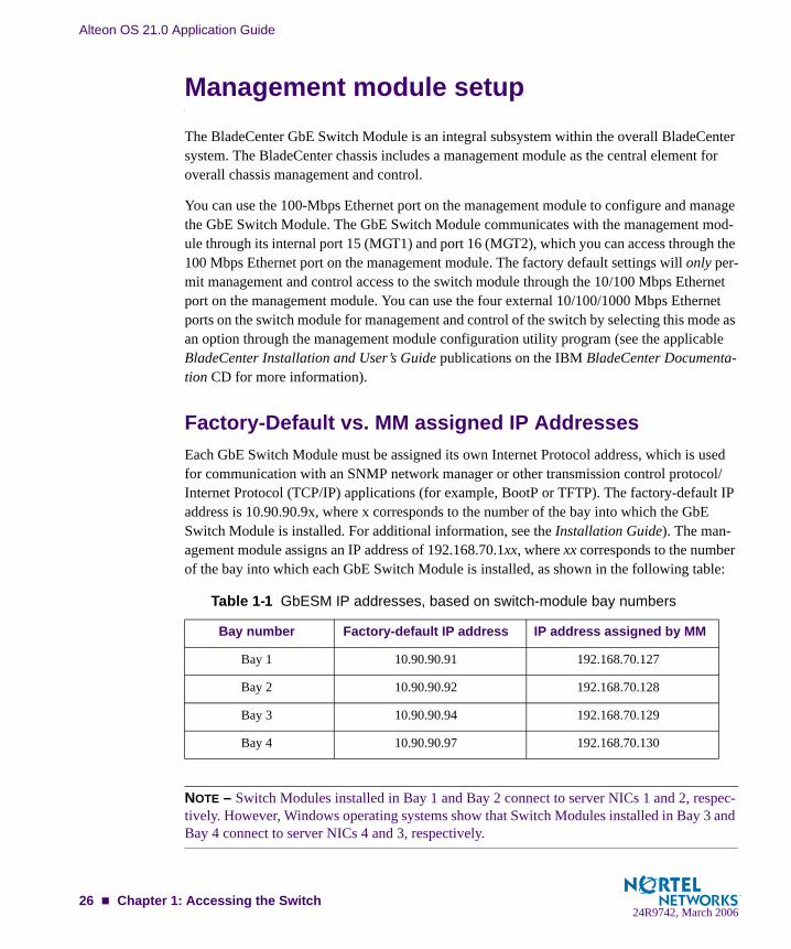
Factory-Default vs. MM assigned IP AddressesEach GbE Switch Module must be assigned its own Internet Protocol address, which is used for communication with an SNMP network manager or other transmission control protocol/Internet Protocol (TCP/IP) applications (for example, BootP or TFTP). The factory-default IP address is 10.90.90.9x, where x corresponds to the number of the bay into which the GbE Switch Module is installed. For additional information, see the Installation Guide). The man-agement module assigns an IP address of 192.168.70.1xx, where xx corresponds to the number of the bay into which each GbE Switch Module is installed, as shown in the following table:
NOTE – Switch Modules installed in Bay 1 and Bay 2 connect to server NICs 1 and 2, respec-tively. However, Windows operating systems show that Switch Modules installed in Bay 3 and Bay 4 connect to server NICs 4 and 3, respectively.
Table 1-1 GbESM IP addresses, based on switch-module bay numbers
Bay number Factory-default IP address IP address assigned by MM
Bay 1 10.90.90.91 192.168.70.127
Bay 2 10.90.90.92 192.168.70.128
Bay 3 10.90.90.94 192.168.70.129
Bay 4 10.90.90.97 192.168.70.130
26 Chapter 1: Accessing the Switch24R9742, March 2006
Alteon OS 21.0 Application Guide
Default GatewayThe default Gateway IP address determines where packets with a destination address outside the current subnet should be sent. Usually, the default Gateway is a router or host acting as an IP gateway to handle connections to other subnets of other TCP/IP networks. If you want to access the GbE Switch Module from outside your local network, use the management module to assign a default Gateway address to the GbE Switch Module. Choose I/O Module Tasks > Configuration from the navigation pane on the left, and enter a default Gateway address (for example, 192.168.70.125). Click Save.
Configure management module for switch accessComplete the following initial configuration steps:
1. Connect the Ethernet port of the management module to a 10/100 Mbps network (with access to a management station) or directly to a management station.
2. Access and log on to the management module, as described in the BladeCenter Manage-ment Module User’s Guide on the IBM BladeCenter Documentation CD. The management module provides the appropriate IP addresses for network access (see the applicable Bla-deCenter Installation and User’s Guide publications on the IBM BladeCenter Documenta-tion CD for more information).
3. Select Configuration on the I/O Module Tasks menu on the left side of the BladeCenter management module window. See Figure 1-1.
Chapter 1: Accessing the Switch 2724R9742, March 2006

Alteon OS 21.0 Application Guide
Figure 1-1 Switch management on the BladeCenter management module
4. You can use the default IP addresses provided by the management module, or you can assign a new IP address to the switch module through the management module. You can assign this IP address through one of the following methods:
Manually through the BladeCenter management module.
Automatically through the IBM Director Configuration Wizard
NOTE – If you change the IP address of the GbE Switch Module, make sure that the switch module and the management module both reside on the same subnet. Both management module ports (Ethernet 0 and Ethernet 1) must reside on the same subnet.
28 Chapter 1: Accessing the Switch24R9742, March 2006

Alteon OS 21.0 Application Guide
5. Enable the following features in the management module:
External Ports (I/O Module Tasks > Admin/Power/Restart > Advance Setup)
External management over all ports (Configuration > Advanced Configuration)This setting is required if you want to access the management network through the exter-nal ports on the GbE Switch Module.
The default value is Disabled for both features. If these features are not already enabled, change the value to Enabled, then Save.
NOTE – In Advanced Configuration > Advanced Setup, enable “Preserve new IP configura-tion on all switch resets,” to retain the switch’s IP interface when you restore factory defaults. This setting preserves the management port’s IP address in the management module’s memory, so you maintain connectivity to the management module after a reset.
You can now start a Telnet session, Browser-Based Interface (Web) session, or a Secure Shell session to the GbE Switch Module.
Using TelnetUse the management module to access the GbE Switch Module through Telnet. Choose I/O Module Tasks > Configuration from the navigation pane on the left. Select a bay number and click Advanced Configuration > Start Telnet/Web Session > Start Telnet Session. A Telnet window opens a connection to the Switch Module (requires Java 1.4 Plug-in).
Once that you have configured the GbE Switch Module with an IP address and gateway, you can access the switch from any workstation connected to the management network. Telnet access provides the same options for user and administrator access as those available through the management module, minus certain telnet and management commands.
To establish a Telnet connection with the switch, you can run the Telnet program on your workstation and issue the Telnet command, followed by the switch IP address:
telnet <switch IP address>
Chapter 1: Accessing the Switch 2924R9742, March 2006

Alteon OS 21.0 Application Guide
Connect to the Switch via SSH The SSH (Secure Shell) protocol enables you to securely log into another computer over a net-work to execute commands remotely. As a secure alternative to using Telnet to manage switch configuration, SSH ensures that all data sent over the network is encrypted and secure. For more information, see “Secure Shell and Secure Copy” on page 48. For more information on the command-line interface (CLI), see the Alteon OS Command Reference.
BOOTP Relay AgentThe GbE Switch Module can function as a Bootstrap Protocol relay agent, enabling the switch to forward a client request for an IP address up to two BOOTP servers with IP addresses that have been configured on the switch.
When a switch receives a BOOTP request from a BOOTP client requesting an IP address, the switch acts as a proxy for the client. The request is then forwarded as a UDP Unicast MAC layer message to two BOOTP servers whose IP addresses are configured on the switch. The servers respond to the switch with a Unicast reply that contains the default gateway and IP address for the client. The switch then forwards this reply back to the client.
Figure 1-2 figure shows a basic BOOTP network example.
Figure 1-2 BOOTP Relay Agent Configuration
The use of two servers provide failover redundancy. The client request is forwarded to both BOOTP servers configured on the switch. However, no health checking is supported.
Configuring the BOOTP Relay Agent To enable the GbE Switch Module to be the BOOTP forwarder, you need to configure the BOOTP server IP addresses on the switch, and enable BOOTP relay on the interface(s) on which the BOOTP requests are received.
BOOT Client asks for IP from BOOTP server
BladeCenter acts as BOOTP Relay Agent
BOOTP Server
Boston Raleigh
20.1.1.1 10.1.1.2BladeCenter
BladeCenterBladeCenter
30 Chapter 1: Accessing the Switch24R9742, March 2006

Alteon OS 21.0 Application Guide
Generally, you should configure the command on the switch IP interface that is closest to the client, so that the BOOTP server knows from which IP subnet the newly allocated IP address should come.
Use the following commands to configure the switch as a BOOTP relay agent:
Use the following command to enable the Relay functionality on an IP interface:
Using the Browser-Based InterfaceUse the management module to access the GbE Switch Module through a Web session. Choose I/O Module Tasks > Configuration from the navigation pane on the left. Select a bay number and click Advanced Configuration > Start Telnet/Web Session > Start Web Session. A browser window opens a connection to the Switch Module (requires Java 1.4 Plug-in).
The Browser-based Interface (BBI) provides access to the common configuration, manage-ment and operation features of the GbE Switch Module through your Web browser. For more information, refer to the BBI Quick Guide.
By default, BBI access is enabled on the switch (/cfg/sys/access/http ena).
To establish a BBI connection with the switch, you can run a browser on your workstation and point it to the IP address of the Switch Module.
The BBI is organized at a high level as follows:
Configuration – this section provides access to the configuration elements for the entire switch:
Switch – this menu provides access to the switch configuration elements.
Spanning Tree Groups – add and configure the switch spanning tree groups and the various configuration elements associated with them.
>> # /cfg/l3/bootp>> Bootstrap Protocol Relay# addr <IP-address>(IP address of BOOTP server)>> Bootstrap Protocol Relay# addr2<IP-address>(IP address of 2nd BOOTP server)>> Bootstrap Protocol Relay# on (Globally turn BOOTP relay on)>> Bootstrap Protocol Relay# off (Globally turn BOOTP relay off) >> Bootstrap Protocol Relay# cur (Display current configuration)
>> # /cfg/l3/if <interface number>/relay ena
Chapter 1: Accessing the Switch 3124R9742, March 2006

Alteon OS 21.0 Application Guide
Virtual LANs – add and configure the VLANs for the switch which includes select-ing the participating ports and associated Spanning Tree Group.
RMON – configure remote monitoring functions.
IP Routing – configure all of the IP related information.
L4 Switching – configure layer 4 information, including server load-balancing fea-tures and filters
Layer 7 Resource Definition – configure layer 7 resources
Virtual Routing – configure Virtual Router Redundancy Protocol
Statistics – this section provides access to the switch statistics and state information.
Dashboard – the Dashboard displays settings and operating status of a variety of switch features.
Configuring BBI Access via HTTPTo enable BBI access via HTTP, use the following command:
To change the HTTP web server port from the default port 80, use the following command:
To access the GbESM via the Browser-Based Interface, open a Web browser window and type in the URL using the IP interface address of the GbESM, such as http://10.10.10.1.
Configuring BBI Access via HTTPSThe BBI can also be accessed through a secure HTTPS connection over the management mod-ule interface or the console port.
To enable BBI Access via HTTPS, use the following command:
To change the HTTPS Web server port number from the default port 443, use the following command:
/cfg/sys/access/http ena
/cfg/sys/access/wport <x>
/cfg/sys/access/https/https ena
/cfg/sys/access/https/port <x>
32 Chapter 1: Accessing the Switch24R9742, March 2006

Alteon OS 21.0 Application Guide
Accessing the BBI via HTTPS requires that you generate a certificate to be used during the key exchange. A default certificate is created the first time HTTPS is enabled, but you can create a new certificate defining the information you want to be used in the various fields.
The certificate can be saved to flash for use if the GbESM is rebooted by using the apply and save commands.
When a client (e.g. web browser) connects to the GbESM, the client is asked to accept the cer-tificate and can verify that the fields are what the client expected. Once BBI access is granted to the client, you can use the BBI.
Using SNMPThe switch software provides Simple Network Management Protocol (SNMP) v1.0 support for access through any network management software, such as IBM Director or HP-OpenView.
SNMP is enabled by default. To change the setting, use the /cfg/sys/access/snmp command, and choose SNMP access as (disabled, read-only, or read-write) [d/r/w].
To access the SNMP agent on the GbE Switch Module, the read and write community strings on the SNMP manager should be configured to match those on the switch. The default read community string on the switch is public and the default write community string is private.
The read and write community strings on the switch can be changed using the following com-mands on the CLI:
>> /cfg/sys/access/https/generateCountry Name (2 letter code) [ ]: <country code>State or Province Name (full name) []: <state>Locality Name (eg, city) []: <city>Organization Name (eg, company) []: <company>Organizational Unit Name (eg, section) []: <org. unit>Common Name (eg, YOUR name) []: <name>Email (eg, email address) []: <email address>Confirm generating certificate? [y/n]: yGenerating certificate. Please wait (approx 30 seconds)restarting SSL agent
>> /cfg/sys/ssnmp/rcomm
Chapter 1: Accessing the Switch 3324R9742, March 2006

Alteon OS 21.0 Application Guide
and
The SNMP manager should be able to reach the management interface, or any one of the IP interfaces on the switch.
For the SNMP manager to receive the traps sent out by the SNMP agent on the switch, the trap host on the switch should be configured with the following command:
>> /cfg/sys/ssnmp/wcomm
/cfg/sys/ssnmp/<trap1|trap2>
34 Chapter 1: Accessing the Switch24R9742, March 2006

Alteon OS 21.0 Application Guide
Alteon OS supports the following standard MIBs on the GbE Switch Module:
RFC 1155, Structure and identification of management information for TCP/IP-based internets. M.T. Rose, K. McCloghrie. May-01-1990.RFC 1157, Simple Network Management Protocol (SNMP). J.D. Case, M. Fedor, M.L. Schoffstall, C. Davin. May-01-1990.RFC 1212, Concise MIB definitions. M.T. Rose, K. McCloghrie. Mar-01-1991.RFC 1213, Management Information Base for Network Management of TCP/IP-based internets: MIB-II. K. McCloghrie, M.T. Rose. Mar-01-1991.RFC 1493, Definitions of Managed Objects for Bridges. E. Decker, P. Langille, A. Rijs-inghani, K. McCloghrie. July 1993.RFC 1573, Evolution of the Interfaces Group of MIB-II. K. McCloghrie, F. Kastenholz. January 1994.RFC 1643, Definitions of Managed Objects for the Ethernet-like Interface Types. F. Kas-tenholz. July 1994.RFC 2037, Entity MIB using SMIv2. K. McCloghrie, A. Bierman. October 1996. (Partial Support)
For more information on using SNMP, see the Alteon OS Command Reference.
Using the Console PortThe RS-232 console port allows you to connect directly to the GbESM from a computer or ter-minal. The console port provides an alternative path to manage and configure the switch. The console connection functions the same as an Ethernet connection for remote access to the com-mand-line interface (CLI).
To establish a console (DCE) connection, connect an 8-pin DIN to DB9 serial console cable cable (26K6541) between the GbESM console port and an ASCII terminal or a computer run-ning ASCII terminal emulation software that is set to the following values:
Baud Rate: 9600 Data Bits: 8 Parity: None Stop Bits: 1 Flow Control: None Emulate: VT100
Chapter 1: Accessing the Switch 3524R9742, March 2006

Alteon OS 21.0 Application Guide
Securing Access to the SwitchSecure switch management is needed for environments that perform significant management functions across the Internet. The following are some of the functions for secured manage-ment:
Limiting management users to a specific IP address range. See “Setting Allowable Source IP Address Ranges” on page 37
Authentication and authorization of remote administrators: see “RADIUS Authentication and Authorization” on page 38
Encryption of management information exchanged between the remote administrator and the switch: see “Secure Shell and Secure Copy” on page 48
The following topics are addressed in this section:
“Setting Allowable Source IP Address Ranges” on page 37
“RADIUS Authentication and Authorization” on page 38
“TACACS+ Authentication” on page 42
“Secure Shell and Secure Copy” on page 48
36 Chapter 1: Accessing the Switch24R9742, March 2006
Alteon OS 21.0 Application Guide
Setting Allowable Source IP Address RangesTo limit access to the switch without having to configure filters for each switch port, you can set a source IP address (or range) that will be allowed to connect to the switch IP interface through Telnet, SSH, SNMP, or the Alteon OS Browser-Based Interface (BBI). This will also help to prevent spoofing or attacks on the switch’s TCP/IP stack.
When an IP packet reaches the switch, the source IP address is checked against the range of addresses defined by the management network and mask, (mnet and mmask). If the source IP address of the host or hosts are within this range, they are allowed to attempt to log in. Any packet addressed to a switch IP interface with a source IP address outside this range is dis-carded.
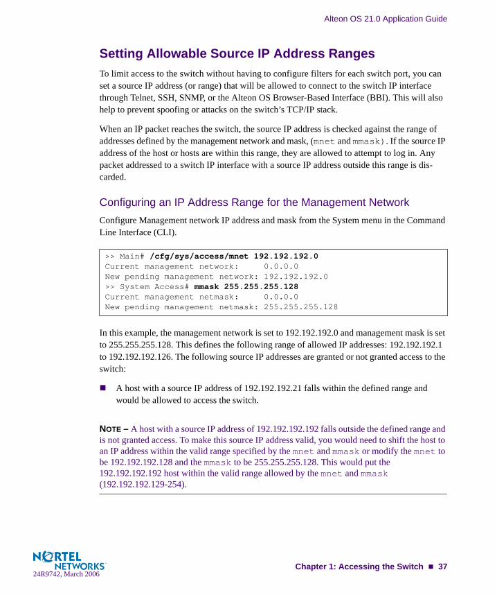
Configuring an IP Address Range for the Management NetworkConfigure Management network IP address and mask from the System menu in the Command Line Interface (CLI).
In this example, the management network is set to 192.192.192.0 and management mask is set to 255.255.255.128. This defines the following range of allowed IP addresses: 192.192.192.1 to 192.192.192.126. The following source IP addresses are granted or not granted access to the switch:
A host with a source IP address of 192.192.192.21 falls within the defined range and would be allowed to access the switch.
NOTE – A host with a source IP address of 192.192.192.192 falls outside the defined range and is not granted access. To make this source IP address valid, you would need to shift the host to an IP address within the valid range specified by the mnet and mmask or modify the mnet to be 192.192.192.128 and the mmask to be 255.255.255.128. This would put the 192.192.192.192 host within the valid range allowed by the mnet and mmask (192.192.192.129-254).
>> Main# /cfg/sys/access/mnet 192.192.192.0Current management network: 0.0.0.0New pending management network: 192.192.192.0>> System Access# mmask 255.255.255.128Current management netmask: 0.0.0.0New pending management netmask: 255.255.255.128
Chapter 1: Accessing the Switch 3724R9742, March 2006
Alteon OS 21.0 Application Guide
RADIUS Authentication and AuthorizationAlteon OS supports the RADIUS (Remote Authentication Dial-in User Service) method to authenticate and authorize remote administrators for managing the switch. This method is based on a client/server model. The Remote Access Server (RAS)—the switch—is a client to the back-end database server. A remote user (the remote administrator) interacts only with the RAS, not the back-end server and database.
RADIUS authentication consists of the following components:
A protocol with a frame format that utilizes UDP over IP (based on RFC 2138 and 2866)
A centralized server that stores all the user authorization information
A client, in this case, the switch
The GbE Switch Module—acting as the RADIUS client—communicates to the RADIUS server to authenticate and authorize a remote administrator using the protocol definitions spec-ified in RFC 2138 and 2866. Transactions between the client and the RADIUS server are authenticated using a shared key that is not sent over the network. In addition, the remote administrator passwords are sent encrypted between the RADIUS client (the switch) and the back-end RADIUS server.
How Radius Authentication Works
1. Remote administrator connects to the switch and provides user name and password.
2. Using Authentication/Authorization protocol, the switch sends request to authentication server.
3. Authentication server checks the request against the user ID database.
4. Using RADIUS protocol, the authentication server instructs the switch to grant or deny administrative access.
Configuring RADIUS on the SwitchUse the following procedure to configure Radius authentication on your GbE Switch Module. For more information, see Appendix B, “Radius Server Configuration Notes.”
38 Chapter 1: Accessing the Switch24R9742, March 2006

Alteon OS 21.0 Application Guide
1. Turn RADIUS authentication on, then configure the Primary and Secondary RADIUS servers.
2. Configure the RADIUS secret.
3. If desired, you may change the default TCP port number used to listen to RADIUS.
The well-known port for RADIUS is 1645.
4. Configure the number retry attempts for contacting the RADIUS server, and the timeout period.
>> Main# /cfg/sys/radius (Select the RADIUS Server menu)>> RADIUS Server# on (Turn RADIUS on)Current status: OFFNew status: ON>> RADIUS Server# prisrv 10.10.1.1 (Enter primary server IP)Current primary RADIUS server: 0.0.0.0New pending primary RADIUS server: 10.10.1.1>> RADIUS Server# secsrv 10.10.1.2 (Enter secondary server IP)Current secondary RADIUS server: 0.0.0.0New pending secondary RADIUS server: 10.10.1.2
>> RADIUS Server# secretEnter new RADIUS secret: <1-32 character secret>
!CAUTION—If you configure the RADIUS secret using any method other than through the con-sole port or management module, the secret may be transmitted over the network as clear text.
>> RADIUS Server# portCurrent RADIUS port: 1645Enter new RADIUS port [1500-3000]: <port number>
>> RADIUS Server# retriesCurrent RADIUS server retries: 3Enter new RADIUS server retries [1-3]: < server retries>>> RADIUS Server# timeCurrent RADIUS server timeout: 3Enter new RADIUS server timeout [1-10]: 10 (Enter the timeout period in minutes)
Chapter 1: Accessing the Switch 3924R9742, March 2006

Alteon OS 21.0 Application Guide
RADIUS Authentication Features in Alteon OSAlteon OS supports the following Radius authentication features:
Supports Radius client on the switch, based on the protocol definitions in RFC 2138 and RFC 2866.
Allows RADIUS secret password up to 32 bytes and less than 16 octets.
Supports secondary authentication server so that when the primary authentication server is unreachable, the switch can send client authentication requests to the secondary authen-tication server. Use the /cfg/sys/radius/cur command to show the currently active RADIUS authentication server.
Supports user-configurable RADIUS server retry and time-out values:
Time-out value = 1-10 seconds
Retries = 1-3
The switch will time out if it does not receive a response from the RADIUS server in 1-3 retries. The switch will also automatically retry connecting to the RADIUS server before it declares the server down.
Supports user-configurable RADIUS application port.The default is 1645/UDP-based on RFC 2138. Port 1812 is also supported.
Allows network administrator to define privileges for one or more specific users to access the switch at the RADIUS user database.
SecurID is supported if the RADIUS server can do an ACE/Server client proxy. The pass-word is the PIN number, plus the token code of the SecurID card.
40 Chapter 1: Accessing the Switch24R9742, March 2006

Alteon OS 21.0 Application Guide
Switch User AccountsThe user accounts listed in Table 1-2 can be defined in the RADIUS server dictionary file.
RADIUS Attributes for Alteon OS User PrivilegesWhen the user logs in, the switch authenticates his/her level of access by sending the RADIUS access request, that is, the client authentication request, to the RADIUS authentication server.
Table 1-2 User Access Levels
User Account Description and Tasks Performed Password
User The User has no direct responsibility for switch management. He/she can view all switch status information and statistics but cannot make any configuration changes to the switch.
user
SLB Operator The SLB Operator manages content servers and other Internet services and their loads. In addition to being able to view all switch information and statistics, the SLB Operator can enable/disable servers using the SLB operation menu.
slboper
Layer 4 Operator The Layer 4 Operator manages traffic on the lines leading to the shared Internet services. This user currently has the same access level as the SLB operator. This level is reserved for future use, to provide access to operational commands for operators managing traffic on the line leading to the shared Internet services.
l4oper
Operator The Operator manages all functions of the switch. In addition to SLB Operator functions, the Operator can reset ports or the entire switch.
oper
SLB Administrator The SLB Administrator configures and manages content servers and other Internet services and their loads. In addition to SLB Operator functions, the SLB Administrator can configure param-eters on the SLB menus, with the exception of not being able to configure filters or bandwidth management.
slbadmin
Layer 4 Administrator The Layer 4 Administrator configures and manages traffic on the lines leading to the shared Internet services. In addition to SLB Administrator functions, the Layer 4 Administrator can config-ure all parameters on the SLB menus, including filters and band-width management.
l4admin
Administrator The super-user Administrator has complete access to all menus, information, and configuration commands on the switch, includ-ing the ability to change both the user and administrator pass-words.
admin
Chapter 1: Accessing the Switch 4124R9742, March 2006

Alteon OS 21.0 Application Guide
If the remote user is successfully authenticated by the authentication server, the switch will verify the privileges of the remote user and authorize the appropriate access. The administrator has an option to allow backdoor access via Telnet (/cfg/sys/radius/telnet). The default is disable for Telnet access. The adminstrator also can enable secure backdoor (/cfg/sys/radius/secbd), to allow access if both the primary and the secondary TACACS+ servers fail to respond.
NOTE – To obtain the RADIUS backdoor password for your GbESM, contact your IBM Ser-vice and Support line.
All user privileges, other than those assigned to the User and the Administrator, have to be defined in the RADIUS dictionary. Radius attribute 1, which is built into all Radius servers, defines the User. Radius attribute 6 defines the Administrator. The file name of the dictionary is RADIUS vendor-dependent. The following Radius attributes are defined for Alteon OS user privileges levels:
TACACS+ AuthenticationAlteon OS supports authentication and authorization with networks using the Cisco Systems TACACS+ protocol. The GbE Switch Module functions as the Network Access Server (NAS) by interacting with the remote client and initiating authentication and authorization sessions with the TACACS+ access server. The remote user is defined as someone requiring manage-ment access to the GbE Switch Module either through a data or management port.
Table 1-3 Alteon OS-proprietary Attributes for Radius
User Name/Access User-Service-Type Value
User Vendor-supplied 255
SLB Operator Vendor-supplied 254
Layer 4 Operator Vendor-supplied 253
Operator Vendor-supplied 252
SLB Administrator Vendor-supplied 251
Layer 4 Administrator Vendor-supplied 250
42 Chapter 1: Accessing the Switch24R9742, March 2006

Alteon OS 21.0 Application Guide
TACACS+ offers the following advantages over RADIUS:
TACACS+ uses TCP-based connection-oriented transport; whereas RADIUS is UDP-based. TCP offers a connection-oriented transport, while UDP offers best-effort delivery. RADIUS requires additional programmable variables such as re-transmit attempts and time-outs to compensate for best-effort transport, but it lacks the level of built-in support that a TCP transport offers.
TACACS+ offers full packet encryption whereas RADIUS offers password-only encryp-tion in authentication requests.
TACACS+ separates authentication, authorization and accounting.
How TACACS+ Authentication WorksTACACS+ works much in the same way as RADIUS authentication as described on page 38.
1. Remote administrator connects to the switch and provides user name and password.
2. Using Authentication/Authorization protocol, the switch sends request to authentication server.
3. Authentication server checks the request against the user ID database.
4. Using TACACS+ protocol, the authentication server instructs the switch to grant or deny administrative access.
If additional authorization checking is needed, the switch checks with a TACACS+ server to determine if the user is granted permission to use a particular command.
TACACS+ Authentication Features in Alteon OSAuthentication is the action of determining the identity of a user, and is generally done when the user first attempts to log in to a device or gain access to its services. Alteon OS supports ASCII inbound login to the device. Alteon OS does not support PAP, CHAP and ARAP login methods, and one-time password authentication.
Authorization
Authorization is the action of determining a user’s privileges on the device, and usually takes place after authentication.
Chapter 1: Accessing the Switch 4324R9742, March 2006

Alteon OS 21.0 Application Guide
The default mapping between TACACS+ authorization levels and Alteon OS management access levels is shown in Table 1-4. The authorization levels must be defined on the TACACS+ server.
Alternate mapping between TACACS+ authorization levels and Alteon OS management access levels is shown in Table 1-5. Use the command /cfg/sys/tacacs/cmap ena to use the alternate TACACS+ authorization levels.
If the remote user is successfully authenticated by the authentication server, the switch will verify the privileges of the remote user and authorize the appropriate access. The administrator has an option to allow backdoor access via Telnet (/cfg/sys/tacacs/telnet). The default is disable for Telnet access. The adminstrator also can enable secure backdoor (/cfg/sys/tacacs/secbd), to allow access if both the primary and the secondary TACACS+ servers fail to respond.
Table 1-4 Default TACACS+ Authorization Levels
Alteon OS User Access Level TACACS+ level
user 0
slboper 1
l4oper 2
oper 3
slbadmin 4
l4admin 5
admin 6
Table 1-5 Alternate TACACS+ Authorization Levels
Alteon OS User Access Level TACACS+ level
user 0 - 1
slboper 2 - 3
l4oper 4 - 5
oper 6 - 8
slbadmin 9 - 11
l4admin 12 - 13
admin 14 - 15
44 Chapter 1: Accessing the Switch24R9742, March 2006

Alteon OS 21.0 Application Guide
NOTE – To obtain the TACACS+ backdoor password for your GbESM, contact your IBM Service and Support line.
Accounting
Accounting is the action of recording a user's activities on the device for the purposes of billing and/or security. It follows the authentication and authorization actions. If the authentication and authorization is not performed via TACACS+, there are no TACACS+ accounting mes-sages sent out.
You can use TACACS+ to record and track software logins, configuration changes, and inter-active commands.
The GbE Switch Module supports the following TACACS+ accounting attributes:
protocol (console/telnet/ssh/http)
start_time
stop_time
elapsed_time
disc-cause
NOTE – When using the Browser-Based Interface, the TACACS+ Accounting Stop records are sent only if the Quit button on the browser is clicked.
Command Authorization and Logging
When TACACS+ Command Authorization is enabled (/cfg/sys/tacacs/cauth ena), Alteon OS configuration commands are sent to the TACACS+ server for authorization. When TACACS+ Command Logging is enabled (/cfg/sys/tacacs/clog ena), Alteon OS configuration commands are logged on the TACACS+ server.
Chapter 1: Accessing the Switch 4524R9742, March 2006

Alteon OS 21.0 Application Guide
The following examples illustrate the format of Alteon OS commands sent to the TACACS+ server:
The following rules apply to TACACS+ command authorization and logging:
Only commands from a Console, Telnet, or SSH connection are sent for authorization and logging. SNMP, BBI, or file-copy commands (for example, TFTP or sync) are not sent.
Only leaf-level commands are sent for authorization and logging. For example, /cfg is not sent, but /cfg/l3/tacacs/cauth is sent.
The full path of each command is sent for authorization and logging. For example, /cfg/sys/tacacs/cauth.
Command arguments are not sent for authorization. For /cauth ena, only /cauth is authorized. The command and its first argument are logged, if issued on the same line.
Only executed commands are logged.
Invalid commands are checked by Alteon OS, and are not sent for authorization or log-ging.
Authorization is performed on each leaf-level command separately. If the user issues mul-tiple commands at once, each command is sent separately as a full path.
Only the following global commands are sent for authorization and logging: applydiffpingrevertsavetelnettraceroute
authorization request, cmd=cfgtree, cmd-arg=/cfg/l3/ifaccounting request, cmd=/cfg/l3/if, cmd-arg=1authorization request, cmd=cfgtree, cmd-arg=/cfg/l3/if/enaaccounting request, cmd=/cfg/l3/if/enaauthorization request, cmd=cfgtree, cmd-arg=/cfg/l3/if/addraccounting request, cmd=/cfg/l3/if/addr, cmd-arg=10.90.90.91
authorization request, cmd=applyaccounting request, cmd=apply
46 Chapter 1: Accessing the Switch24R9742, March 2006

Alteon OS 21.0 Application Guide
TACACS+ Password Change
Alteon OS 21.0 supports TACACS+ password change. When enabled, users can change their passwords after successful TACACS+ authorization. Use the /cfg/sys/tacacs/chpass to enable or disable this feature.
Use the following commands to change the password for the primary and secondary TACACS+ servers:
Configuring TACACS+ Authentication on the Switch
1. Turn TACACS+ authentication on, then configure the Primary and Secondary TACACS+ servers.
2. Configure the TACACS+ secret and second secret.
3. If desired, you may change the default TCP port number used to listen to TACACS+.
>> # /cfg/sys/tacacs/passch_p (Change primary TACACS+ password)
>> # /cfg/sys/tacacs/passch_s (Change secondary TACACS+ password)
>> Main# /cfg/sys/tacacs (Select the TACACS+ Server menu)>> TACACS+ Server# on (Turn TACACS+ on)Current status: OFFNew status: ON>> TACACS+ Server# prisrv 10.10.1.1 (Enter primary server IP)Current primary TACACS+ server: 0.0.0.0New pending primary TACACS+ server: 10.10.1.1>> TACACS+ Server# secsrv 10.10.1.2 (Enter secondary server IP)Current secondary TACACS+ server: 0.0.0.0New pending secondary TACACS+ server: 10.10.1.2
>> TACACS+ Server# secretEnter new TACACS+ secret: <1-32 character secret>>> TACACS+ Server# secret2Enter new TACACS+ second secret: <1-32 character secret>
!CAUTION—If you configure the TACACS+ secret using any method other than a direct con-sole connection or through a secure management module connection, the secret may be trans-mitted over the network as clear text.
Chapter 1: Accessing the Switch 4724R9742, March 2006

Alteon OS 21.0 Application Guide
The well-known port for TACACS+ is 49.
4. Configure the number retry attempts for contacting the TACACS+ server, and the time-out period.
5. Apply and save the configuration.
Secure Shell and Secure Copy Secure Shell (SSH) and Secure Copy (SCP) use secure tunnels to encrypt and secure messages between a remote administrator and the switch. Telnet does not provide this level of security. The Telnet method of managing an GbE Switch Module does not provide a secure connection.
SSH is a protocol that enables remote administrators to log securely into the GbE Switch Mod-ule over a network to execute management commands.
SCP is typically used to copy files securely from one machine to another. SCP uses SSH for encryption of data on the network. On a GbE Switch Module, SCP is used to download and upload the switch configuration via secure channels.
The benefits of using SSH and SCP are listed below:
Authentication of remote administratorsIdentifying the administrator using Name/PasswordAuthorization of remote administratorsDetermining the permitted actions and customizing service for individual administratorsEncryption of management messages Encrypting messages between the remote administrator and switch Secure copy support
The Alteon OS implementation of SSH supports both versions 1.5 and 2.0. and supports SSH clients version 1.5—2.x. The following SSH clients have been tested:
>> TACACS+ Server# portCurrent TACACS+ port: 49Enter new TACACS+ port [1-65000]: <port number>
>> TACACS+ Server# retriesCurrent TACACS+ server retries: 3Enter new TACACS+ server retries [1-3]: < server retries>>> TACACS+ Server# timeCurrent TACACS+ server timeout: 5Enter new TACACS+ server timeout [4-15]: 10(Enter the timeout period in minutes)
48 Chapter 1: Accessing the Switch24R9742, March 2006

Alteon OS 21.0 Application Guide
SSH 1.2.23 and SSH 1.2.27 for Linux (freeware)SecureCRT 3.0.2 and SecureCRT 3.0.3 for Windows NT (Van Dyke Technologies, Inc.)F-Secure SSH 1.1 for Windows (Data Fellows)Putty SSHCygwin OpenSSHMac X OpenSSHSolaris 8 OpenSSHAxeSSH SSHProSSH Communications Vandyke SSH AF-Secure
Configuring SSH/SCP features on the switchBefore you can use SSH commands, use the following commands to turn on SSH/SCP. SSH and SCP are disabled by default.
To enable or disable the SSH feature:
Begin a Telnet session from the management module and enter the following commands:
>> # /cfg/sys/access/sshd/on (Turn SSH on)Current status: OFFNew status: ON
>> # /cfg/sys/access/sshd/off (Turn SSH off)Current status: ONNew status: OFF
Chapter 1: Accessing the Switch 4924R9742, March 2006

Alteon OS 21.0 Application Guide
To enable or disable SCP apply and save:
Enter the following commands from the switch CLI to enable the SCP putcfg_apply and putcfg_apply_save commands:
Configuring the SCP Administrator PasswordTo configure the scpadm (SCP Administrator) password, first connect to the switch via the management module. For security reasons, the scpadm password may only be configured when connected through the management module.
To configure the password, enter the following command via the CLI. At factory default set-tings, the current SCP administrator password is admin.
>> # /cfg/sys/access/sshd/ena (Enable SCP apply and save)SSHD# apply (Apply the changes to start generating RSA
host and server keys)RSA host key generation starts ...................................................................................................................RSA host key generation completes (lasts 212549 ms)RSA host key is being saved to Flash ROM, please don't reboot the box immediately. RSA server key generation starts ............................................................RSA server key generation completes (lasts 75503 ms)RSA server key is being saved to Flash ROM, please don't reboot the box immediately.------------------------------------------------------------------Apply complete; don't forget to "save" updated configuration.
>> # /cfg/sys/access/sshd/dis (Disable SSH/SCP apply and save)
>> /cfg/sys/access/sshd/scpadmChanging SCP-only Administrator password; validation required...Enter current administrator password: <password>Enter new SCP-only administrator password: <new password>Re-enter new SCP-only administrator password: <new password> New SCP-only administrator password accepted.
50 Chapter 1: Accessing the Switch24R9742, March 2006

Alteon OS 21.0 Application Guide
Using SSH and SCP Client CommandsThis section shows the format for using some client commands. The examples below use 205.178.15.157 as the IP address of a sample switch.
To log in to the switch:
Syntax:
Example:
To download the switch configuration using SCP:
Syntax:
Example:
To upload the configuration to the switch:
Syntax:
Example:
ssh <switch IP address> or ssh -l <login-name> <switch IP address>
>> # ssh 205.178.15.157>> # ssh -l <login-name> 205.178.15.157 (Login to the switch)
scp <switch IP address>:getcfg <local filename>
>> # scp 205.178.15.157:getcfg ad4.cfg
scp <local filename> <switch IP address>:putcfg
>> # scp ad4.cfg 205.178.15.157:putcfg
Chapter 1: Accessing the Switch 5124R9742, March 2006

Alteon OS 21.0 Application Guide
To apply and save the configuration
The apply and save commands are still needed after the last command (scp ad4.cfg 205.178.15.157:putcfg). Or, instead, you can use the following commands:
The diff command is automatically executed at the end of putcfg to notify the remote client of the difference between the new and the current configurations.
putcfg_apply runs the apply command after the putcfg is done.
putcfg_apply_save saves the new configuration to the flash after putcfg_apply is done.
The putcfg_apply and putcfg_apply_save commands are provided because extra apply and save commands are usually required after a putcfg; however, an SCP session is not in an interactive mode at all.
SSH and SCP Encryption of Management MessagesThe following encryption and authentication methods are supported for SSH and SCP:
Server Host Authentication: Client RSA authenticates the switch at the beginning of every connection
Key Exchange: RSA
Encryption: 3DES-CBC, DES
User Authentication: Local password authentication, RADIUS, SecurID (via RADIUS, TACACS+, for SSH only—does not apply to SCP)
Generating RSA Host and Server Keys for SSH AccessTo support the SSH server feature, two sets of RSA keys (host and server keys) are required. The host key is 1024 bits and is used to identify the GbE Switch Module. The server key is 768 bits and is used to make it impossible to decipher a captured session by breaking into the GbE Switch Module at a later time.
When the SSH server is first enabled and applied, the switch automatically generates the RSA host and server keys and is stored in the FLASH memory.
>> # scp ad4.cfg 205.178.15.157:putcfg_apply>> # scp ad4.cfg 205.178.15.157:putcfg_apply_save
52 Chapter 1: Accessing the Switch24R9742, March 2006

Alteon OS 21.0 Application Guide
NOTE – To configure RSA host and server keys, first connect to the GbE Switch Module through the console port or management module (commands are not available via external Tel-net connection), and enter the following commands to generate them manually.
These two commands take effect immediately without the need of an apply command.
When the switch reboots, it will retrieve the host and server keys from the FLASH memory. If these two keys are not available in the flash and if the SSH server feature is enabled, the switch automatically generates them during the system reboot. This process may take several minutes to complete.
The switch can also automatically regenerate the RSA server key. To set the interval of RSA server key autogeneration, use this command:
A value of 0 (zero) denotes that RSA server key autogeneration is disabled. When greater than 0, the switch will autogenerate the RSA server key every specified interval; however, RSA server key generation is skipped if the switch is busy doing other key or cipher generation when the timer expires.
NOTE – The switch will perform only one session of key/cipher generation at a time. Thus, an SSH/SCP client will not be able to log in if the switch is performing key generation at that time, or if another client has logged in immediately prior. Also, key generation will fail if an SSH/SCP client is logging in at that time.
SSH/SCP Integration with Radius AuthenticationSSH/SCP is integrated with RADIUS authentication. After the RADIUS server is enabled on the switch, all subsequent SSH authentication requests will be redirected to the specified RADIUS servers for authentication. The redirection is transparent to the SSH clients.
SSH/SCP Integration with TACACS+ AuthenticationSSH/SCP is integrated with TACACS+ authentication. After the TACACS+ server is enabled on the switch, all subsequent SSH authentication requests are redirected to the specified TACACS+ servers for authentication. The redirection is transparent to the SSH clients.
>> # /cfg/sys/access/sshd/hkeygen (Generates the host key)>> # /cfg/sys/access/sshd/skeygen (Generates the server key)
>> # /cfg/sys/access/sshd/intrval <number of hours (0-24)>
Chapter 1: Accessing the Switch 5324R9742, March 2006

Alteon OS 21.0 Application Guide
SecurID SupportSSH/SCP can also work with SecurID, a token card-based authentication method. The use of SecurID requires the interactive mode during login, which is not provided by the SSH connec-tion.
NOTE – There is no SNMP or Browser-Based Interface (BBI) support for SecurID because the SecurID server, ACE, is a one-time password authentication and requires an interactive ses-sion.
Using SecurID with SSH
Using SecurID with SSH involves the following tasks.
To log in using SSH, use a special username, “ace,” to bypass the SSH authentication.
After an SSH connection is established, you are prompted to enter the username and pass-word (the SecurID authentication is being performed now).
Provide your username and the token in your SecurID card as a regular Telnet user.
Using SecurID with SCP
Using SecurID with SCP can be accomplished in two ways:
Using a RADIUS server to store an administrator password.
You can configure a regular administrator with a fixed password in the RADIUS server if it can be supported. A regular administrator with a fixed password in the RADIUS server can perform both SSH and SCP with no additional authentication required.
Using an SCP-only administrator password.
Use the command, /cfg/sys/access/sshd/scpadm to bypass the checking of SecurID.
An SCP-only administrator’s password is typically used when SecurID is used. For exam-ple, it can be used in an automation program (in which the tokens of SecurID are not avail-able) to back up (download) the switch configurations each day.
NOTE – The SCP-only administrator’s password must be different from the regular administra-tor’s password. If the two passwords are the same, the administrator using that password will not be allowed to log in as an SSH user because the switch will recognize him as the SCP-only administrator. The switch will only allow the administrator access to SCP commands.
54 Chapter 1: Accessing the Switch24R9742, March 2006
Alteon OS 21.0 Application Guide
End User Access ControlAlteon OS allows an administrator to define end user accounts that permit end users to opera-tionally act on their own real servers via the switch CLI commands. Once end user accounts are configured and enabled, the switch will require username/password authentication.
For example, an administrator can assign a user to manage real servers 1 and 2 only. The user can then log into the switch and perform operational commands (effective only until the next switch reboot), to enable or disable the real servers, or change passwords on the real servers.
Considerations for Configuring End User AccountsOnly one user ID can be assigned to a real server resource to enable or disable a real server. Consequently, a single end user may be assigned the maximum number of real servers that can be configured on the switch, to the exclusion of any other users.
A maximum of 10 user IDs are supported on the switch.
The administrator must ensure that all real and backup servers or groups belonging to a virtual service are owned by the same end user ID. The switch will not automatically vali-date configurations. The criterion for displaying virtual service information for end users will be based on the validation of ownership of the first real server in the group for a given virtual server port.
Alteon OS 21.0 supports end user support for Console and Telnet access to the switch. As a result, only very limited access will be granted to the Primary Administrator under the BBI/SSH1 mode of access.
If RADIUS authentication is used, the user password on the Radius server will override the user password on the GbE Switch Module. Also note that the password change com-mand on the switch ONLY modifies the use switch password and has no effect on the user password on the Radius server. Radius authentication and user password cannot be used concurrently to access the switch.
Passwords can be up to 128 characters in length for TACACS, RADIUS, Telnet, SSH, Console, and Web access.
Strong PasswordsThe administrator can require use of Strong Passwords for users to access the GbESM. Strong Passwords enhance security because they make password guessing more difficult.
The following rules apply when Strong Passwords are enabled:
Chapter 1: Accessing the Switch 5524R9742, March 2006

Alteon OS 21.0 Application Guide
Each passwords must be 8 to 14 characters
Within the first 8 characters, the password:
must have at least one number or one symbol
must have both upper and lower case letters
cannot be the same as any four previously used passwords
The following are examples of strong passwords:
1234AbcXyz
Super+User
Exo1cet2
The administrator can choose the number of days allowed before each password expires. When a strong password expires, the user is allowed to log in one last time (last time) to change the password. A warning provides advance notice for users to change the password.
Use the Strong Password menu to configure Strong Passwords.
User Access Control MenuThe end user access control menu is located in the System access menu.
Setting up User IDsUp to 10 user IDs can be configured in the User ID menu.
>> # /cfg/sys/access/user/strongpw
>> # /cfg/sys/access/user
>> # /cfg/sys/access/user/uid 1
56 Chapter 1: Accessing the Switch24R9742, March 2006

Alteon OS 21.0 Application Guide
Defining User Names and Passwords Use the User ID menu to define user names and passwords.
Defining a User’s Access Level The end user is by default assigned to the user access level (also known as class of service, or CoS). CoS for all user accounts have global access to all resources except for User CoS, which has access to view resources that the user owns only. For more information, see Table 1-2 “User Access Levels” on page 41.
To change the user’s level, enter the class of service cos command, and select one of the fol-lowing options:
Assigning One or More Real Servers to the End User A single end user may be assigned up to 64 real servers. Once assigned, the real server cannot be assigned to any other user.
Validating a User’s Configuration
>> User ID 1 # name user1 (Assign name to user ID 1)Current user name:New user name: user1>> User ID 1 # passwd (Assign password to user ID 1)Changing user password; validation required:Enter current admin password: <current administrator password>Enter new user1 password: <new user password>Re-enter new user1 password: <new user password>New user1 password accepted.
>> User ID 1 # cos <user|slboper|l4oper|oper|slbadmin|l4admin|admin>
>> User ID 1 # addEnter real server number: (1-64) 23
User ID 2 # cur name jane , dis, cos user , password valid, offline real servers: 23: 0.0.0.0, disabled, name , weight 1, timeout 20 mins, max-con 200000 24: 0.0.0.0, disabled, name , weight 1, timeout 20 mins, max-con 200000
Chapter 1: Accessing the Switch 5724R9742, March 2006
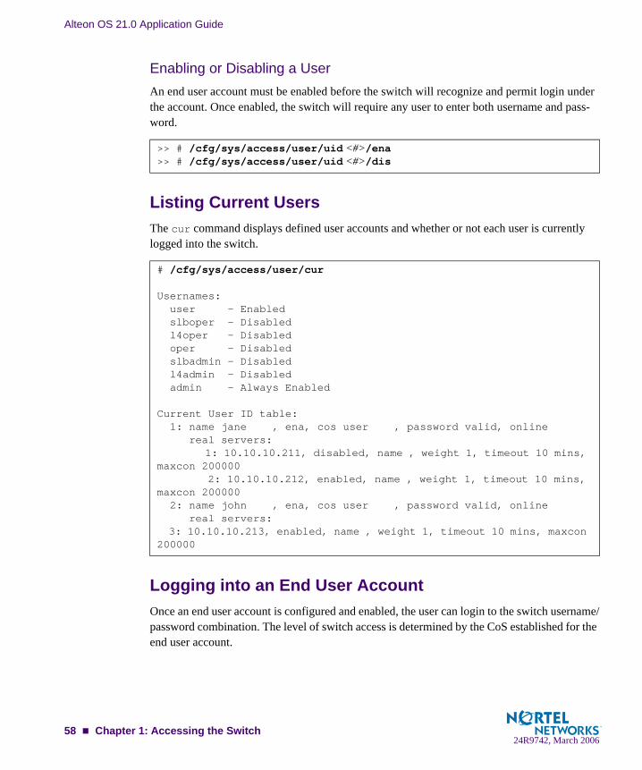
Alteon OS 21.0 Application Guide
Enabling or Disabling a UserAn end user account must be enabled before the switch will recognize and permit login under the account. Once enabled, the switch will require any user to enter both username and pass-word.
Listing Current UsersThe cur command displays defined user accounts and whether or not each user is currently logged into the switch.
Logging into an End User AccountOnce an end user account is configured and enabled, the user can login to the switch username/password combination. The level of switch access is determined by the CoS established for the end user account.
>> # /cfg/sys/access/user/uid <#>/ena>> # /cfg/sys/access/user/uid <#>/dis
# /cfg/sys/access/user/cur
Usernames: user - Enabled slboper - Disabled l4oper - Disabled oper - Disabled slbadmin - Disabled l4admin - Disabled admin - Always Enabled
Current User ID table: 1: name jane , ena, cos user , password valid, online real servers: 1: 10.10.10.211, disabled, name , weight 1, timeout 10 mins, maxcon 200000 2: 10.10.10.212, enabled, name , weight 1, timeout 10 mins, maxcon 200000 2: name john , ena, cos user , password valid, online real servers: 3: 10.10.10.213, enabled, name , weight 1, timeout 10 mins, maxcon 200000
58 Chapter 1: Accessing the Switch24R9742, March 2006

CHAPTER 2VLANs
This chapter describes network design and topology considerations for using Virtual Local Area Networks (VLANs). VLANs are commonly used to split up groups of network users into man-ageable broadcast domains, to create logical segmentation of workgroups, and to enforce security policies among logical segments. The following topics are discussed in this chapter:
“VLANs and Port VLAN ID Numbers” on page 60
“VLAN Tagging” on page 62
“VLAN Topologies and Design Considerations” on page 66
This section discusses how you can logically connect users and segments to a host that supports many logical segments or subnets by using the flexibility of the multiple VLAN system.
“VLANs and Default Gateways” on page 69
NOTE – Basic VLANs can be configured during initial switch configuration (see “Using the Setup Utility” in the Alteon OS Command Reference). More comprehensive VLAN configura-tion can be done from the Command Line Interface (see “VLAN Configuration” as well as “Port Configuration” in the Alteon OS Command Reference).
24R9742, March 200659

Alteon OS 21.0 Application Guide
OverviewSetting up virtual LANs (VLANs) is a way to segment networks to increase network flexibility without changing the physical network topology. With network segmentation, each switch port connects to a segment that is a single broadcast domain. When a switch port is configured to be a member of a VLAN, it is added to a group of ports (workgroup) that belong to one broadcast domain.
Ports are grouped into broadcast domains by assigning them to the same VLAN. Frames received in one VLAN can only be forwarded within that VLAN, and multicast, broadcast, and unknown unicast frames are flooded only to ports in the same VLAN. The GbE Switch Mod-ule supports jumbo frames, up to 9,216 bytes.
VLANs and Port VLAN ID Numbers
VLAN NumbersAlteon OS supports up to 1024 VLANs per switch. Even though the maximum number of VLANs supported at any given time is 1024, each can be identified with any number between 1 and 4095. VLAN 1 is the default VLAN for the external ports and the internal blade ports. VLAN 4095 is used by the management network, which includes the management ports and (by default) the internal blade ports. This configuration allows Serial over LAN (SoL) manage-ment, a feature available on certain server blades.
Viewing VLANs
VLAN information menu:
NOTE – The sample screens that appear in this document might differ slightly from the screens displayed by your system. Screen content varies based on the type of BladeCenter unit that you are using and the firmware versions and options that are installed.
>> Main# info/l2/vlanVLAN Name Status Jumbo Ports---- --------------------------- ------ ----- --------------------1 Default VLAN ena n EXT1 EXT4 INT1-INT142 VLAN 2 ena n EXT2 EXT34095 Mgmt Vlan ena n MGT1 MGT2
60 Chapter 2: VLANs24R9742, March 2006
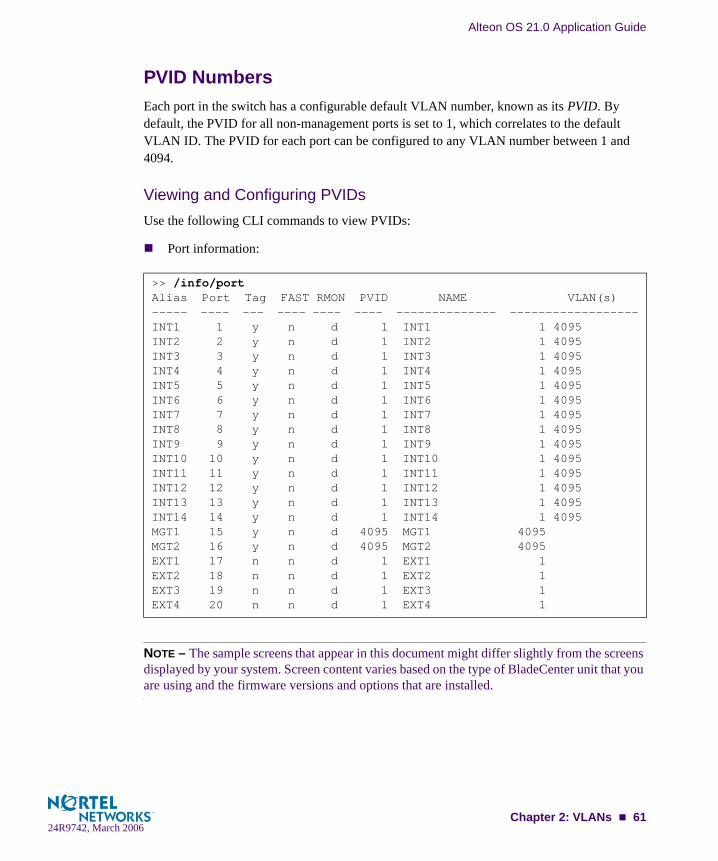
Alteon OS 21.0 Application Guide
PVID NumbersEach port in the switch has a configurable default VLAN number, known as its PVID. By default, the PVID for all non-management ports is set to 1, which correlates to the default VLAN ID. The PVID for each port can be configured to any VLAN number between 1 and 4094.
Viewing and Configuring PVIDsUse the following CLI commands to view PVIDs:
Port information:
NOTE – The sample screens that appear in this document might differ slightly from the screens displayed by your system. Screen content varies based on the type of BladeCenter unit that you are using and the firmware versions and options that are installed.
>> /info/portAlias Port Tag FAST RMON PVID NAME VLAN(s)----- ---- --- ---- ---- ---- -------------- ------------------INT1 1 y n d 1 INT1 1 4095INT2 2 y n d 1 INT2 1 4095INT3 3 y n d 1 INT3 1 4095INT4 4 y n d 1 INT4 1 4095INT5 5 y n d 1 INT5 1 4095INT6 6 y n d 1 INT6 1 4095INT7 7 y n d 1 INT7 1 4095INT8 8 y n d 1 INT8 1 4095INT9 9 y n d 1 INT9 1 4095INT10 10 y n d 1 INT10 1 4095INT11 11 y n d 1 INT11 1 4095INT12 12 y n d 1 INT12 1 4095INT13 13 y n d 1 INT13 1 4095INT14 14 y n d 1 INT14 1 4095MGT1 15 y n d 4095 MGT1 4095MGT2 16 y n d 4095 MGT2 4095EXT1 17 n n d 1 EXT1 1EXT2 18 n n d 1 EXT2 1EXT3 19 n n d 1 EXT3 1EXT4 20 n n d 1 EXT4 1
Chapter 2: VLANs 6124R9742, March 2006

Alteon OS 21.0 Application Guide
Port Configuration:
Each port on the switch can belong to one or more VLANs, and each VLAN can have any number of switch ports in its membership. Any port that belongs to multiple VLANs, however, must have VLAN tagging enabled (see “VLAN Tagging” on page 62).
VLAN TaggingAlteon OS software supports 802.1Q VLAN tagging, providing standards-based VLAN sup-port for Ethernet systems.
Tagging places the VLAN identifier in the frame header of a packet, allowing each port to belong to multiple VLANs. When you add a port to multiple VLANs, you must also enable tagging on that port.
Since tagging fundamentally changes the format of frames transmitted on a tagged port, you must carefully plan network designs to prevent tagged frames from being transmitted to devices that do not support 802.1Q VLAN tags, or devices where tagging is not enabled.
Important terms used with the 802.1Q tagging feature are:
VLAN identifier (VID)—the 12-bit portion of the VLAN tag in the frame header that identifies an explicit VLAN.
Port VLAN identifier (PVID)—a classification mechanism that associates a port with a specific VLAN. For example, a port with a PVID of 3 (PVID =3) assigns all untagged frames received on this port to VLAN 3. Any untagged frames received by the switch are classified with the PVID of the receiving port.
Tagged frame—a frame that carries VLAN tagging information in the header. This VLAN tagging information is a 32-bit field (VLAN tag) in the frame header that identifies the frame as belonging to a specific VLAN. Untagged frames are marked (tagged) with this classification as they leave the switch through a port that is configured as a tagged port.
Untagged frame— a frame that does not carry any VLAN tagging information in the frame header.
>> /cfg/port INT7/pvid 7Current port VLAN ID: 1New pending port VLAN ID: 7
>> Port INT7#
62 Chapter 2: VLANs24R9742, March 2006

Alteon OS 21.0 Application Guide
Untagged member—a port that has been configured as an untagged member of a specific VLAN. When an untagged frame exits the switch through an untagged member port, the frame header remains unchanged. When a tagged frame exits the switch through an untagged member port, the tag is stripped and the tagged frame is changed to an untagged frame.
Tagged member—a port that has been configured as a tagged member of a specific VLAN. When an untagged frame exits the switch through a tagged member port, the frame header is modified to include the 32-bit tag associated with the PVID. When a tagged frame exits the switch through a tagged member port, the frame header remains unchanged.
NOTE – If a 802.1Q tagged frame is received by a port that has VLAN-tagging disabled, then the frame is dropped at the ingress port.
Figure 2-1 Default VLAN settings
Port 1
DA
SA
Data
CRC
Incominguntagged
packet
BS45010A
Port 2 Port 3 Port 4 Port 5
VLAN 1
802.1Q Switch
By default:
Key
All ports are assigned PVID = 1All external ports are untagged members of VLAN 1All internal server ports are tagged members of VLAN 1
PVID = 1
Port 6 ...
DA
SA
Data
CRC
Outgoinguntagged packet
(unchanged)
Port 7
Chapter 2: VLANs 6324R9742, March 2006

Alteon OS 21.0 Application Guide
NOTE – The port numbers specified in these illustrations may not directly correspond to the physical port configuration of your switch model.
When a VLAN is configured, ports are added as members of the VLAN, and the ports are defined as either tagged or untagged (see Figure 2-2 through Figure 2-5).
In Figure 2-1, untagged incoming packets are assigned directly to VLAN 2 (PVID = 2). Port 5 is configured as a tagged member of VLAN 2, and port 7 is configured as an untagged member of VLAN 2.
The default configuration settings for GbE Switch Modules have all external ports set as untagged members of VLAN 1, with all non-management ports configured as PVID = 1. In the default configuration example shown in Figure 2-1 on page 63, all incoming packets are assigned to VLAN 1 by the default port VLAN identifier (PVID =1).
Figure 2-2 through Figure 2-5 illustrate generic examples of VLAN tagging.
NOTE – The port assignments in the following figures are not meant to match the GbE Switch Module.
Figure 2-2 Port-based VLAN assignment
Port 6
DASADataCRC
BS45011A
Port 7 Port 8
Port 1
Por
t 4
Por
t 5
Port 2 Port 3
802.1Q Switch
PVID = 2
Untagged packet
Untagged memberof VLAN 2
Tagged memberof VLAN 2
Before
64 Chapter 2: VLANs24R9742, March 2006

Alteon OS 21.0 Application Guide
As shown in Figure 2-3, the untagged packet is marked (tagged) as it leaves the switch through port 5, which is configured as a tagged member of VLAN 2. The untagged packet remains unchanged as it leaves the switch through port 7, which is configured as an untagged member of VLAN 2.
Figure 2-3 802.1Q tagging (after port-based VLAN assignment)
In Figure 2-4, tagged incoming packets are assigned directly to VLAN 2 because of the tag assignment in the packet. Port 5 is configured as a tagged member of VLAN 2, and port 7 is configured as an untagged member of VLAN 2.
Figure 2-4 802.1Q tag assignment
BS45012A
Port 6 Port 7 Port 8
Port 1P
ort 4
Por
t 5
Port 2 Port 3
802.1Q Switch
Key
PriorityCFI VID
- User_priority- Canonical format indicator- VLAN identifier
PVID = 2 Tagged memberof VLAN 2
Untagged memeberof VLAN 2
After
DA
SA
Data
CRC
(*Recalculated)
Outgoinguntagged packet
(unchanged)
DASADataCRC* Tag
VID = 2Priority
16 bits 3 bits 1 bits 12 bits
8100 CFI
Port 6
DASATagDataCRC
Tagged packet
BS45013A
Port 7 Port 8
Port 1
Por
t 4
Por
t 5
Port 2 Port 3
802.1Q Switch
PVID = 2
Untagged memberof VLAN 2
Tagged memberof VLAN 2
Before
Chapter 2: VLANs 6524R9742, March 2006

Alteon OS 21.0 Application Guide
As shown in Figure 2-5, the tagged packet remains unchanged as it leaves the switch through port 5, which is configured as a tagged member of VLAN 2. However, the tagged packet is stripped (untagged) as it leaves the switch through port 7, which is configured as an untagged member of VLAN 2.
Figure 2-5 802.1Q tagging (after 802.1Q tag assignment)
NOTE – Set the configuration to factory default (/boot/conf factory) to reset all non-management ports to VLAN 1.
VLAN Topologies and Design Considerations
By default, the Alteon OS software is configured so that tagging is disabled on all external ports, and enabled for all internal ports.
By default, the Alteon OS software is configured so that all internal ports are members of VLAN 1. These ports are also members of VLAN 4095 (the management VLAN), to allow Serial over LAN (SoL) management, a feature of certain server blades.
By default, the Alteon OS software is configured so that the management ports are mem-bers of VLAN 4095 (the management VLAN).
BS45014A
Port 6 Port 7 Port 8
Port 1
Por
t 4
Por
t 5
Port 2 Port 3
802.1Q Switch
Key
PriorityCFI VID
- User_priority- Canonical format indicator- VLAN identifier
PVID = 2 Tagged memberof VLAN 2
Untagged memberof VLAN 2
After
DA
SA
Data
CRC* (*Recalculated)
Outgoinguntagged packetchanged(tag removed)
DASADataCRC Tag
VID = 2Priority
16 bits 3 bits 1 bit 12 bits
8100 CFI
66 Chapter 2: VLANs24R9742, March 2006

Alteon OS 21.0 Application Guide
If configuring Spanning Tree Groups (STG), note that Spanning Tree Groups 2-32 may contain only one VLAN.
VLAN configuration rulesVLANs operate according to specific configuration rules. When creating VLANs, consider the following rules that determine how the configured VLAN reacts in any network topology:
All ports involved in trunking and port mirroring must have the same VLAN configura-tion. If a port is on a trunk with a mirroring port, the VLAN configuration cannot be changed. For more information trunk groups, see “Port Trunking Example” on page 79.
All ports that are involved in port mirroring must have memberships in the same VLANs. If a port is configured for port mirroring, the port’s VLAN membership cannot be changed. For more information on configuring port mirroring, see “Monitoring Ports” on page 454.
Note that only Spanning Tree Group 1 can contain multiple VLANs. Spanning Tree Groups 2-32 each can contain only one VLAN.
Example 1: Multiple VLANs with Tagging Adapters
Figure 2-6 Example 1: Multiple VLANs with VLAN-Tagged Gigabit Adapters
BladeCenter
GbE Switch Module Switch Module
GbE
VLAN #3 VLAN #1, 2, 3
Chapter 2: VLANs 6724R9742, March 2006
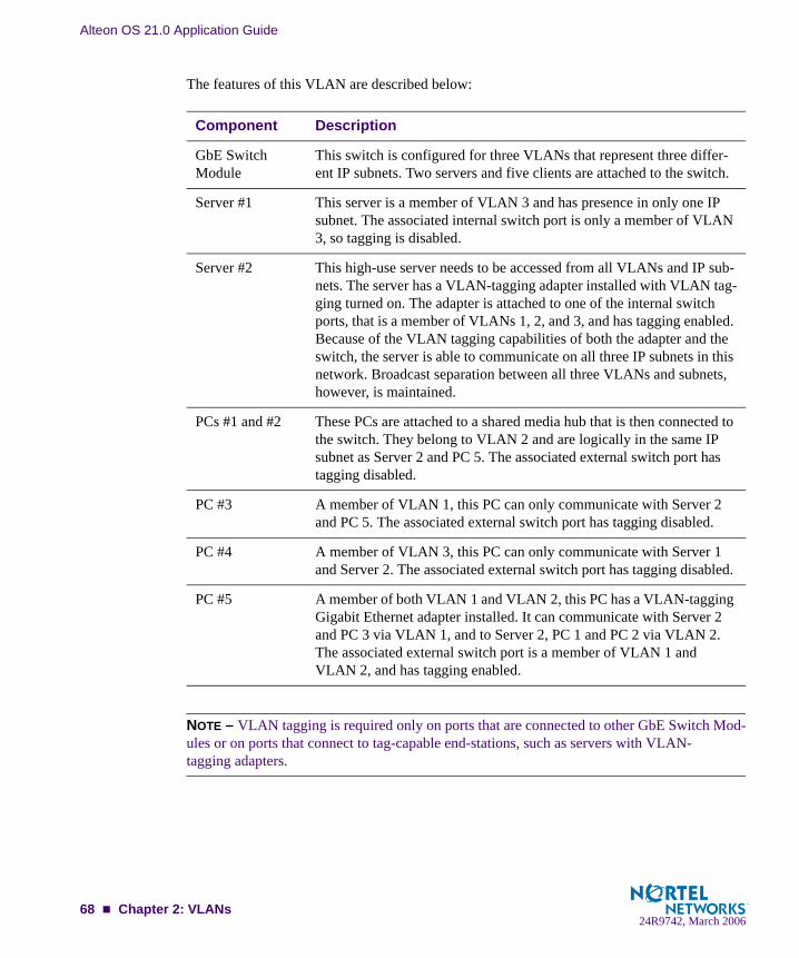
Alteon OS 21.0 Application Guide
The features of this VLAN are described below:
NOTE – VLAN tagging is required only on ports that are connected to other GbE Switch Mod-ules or on ports that connect to tag-capable end-stations, such as servers with VLAN-tagging adapters.
Component Description
GbE Switch Module
This switch is configured for three VLANs that represent three differ-ent IP subnets. Two servers and five clients are attached to the switch.
Server #1 This server is a member of VLAN 3 and has presence in only one IP subnet. The associated internal switch port is only a member of VLAN 3, so tagging is disabled.
Server #2 This high-use server needs to be accessed from all VLANs and IP sub-nets. The server has a VLAN-tagging adapter installed with VLAN tag-ging turned on. The adapter is attached to one of the internal switch ports, that is a member of VLANs 1, 2, and 3, and has tagging enabled. Because of the VLAN tagging capabilities of both the adapter and the switch, the server is able to communicate on all three IP subnets in this network. Broadcast separation between all three VLANs and subnets, however, is maintained.
PCs #1 and #2 These PCs are attached to a shared media hub that is then connected to the switch. They belong to VLAN 2 and are logically in the same IP subnet as Server 2 and PC 5. The associated external switch port has tagging disabled.
PC #3 A member of VLAN 1, this PC can only communicate with Server 2 and PC 5. The associated external switch port has tagging disabled.
PC #4 A member of VLAN 3, this PC can only communicate with Server 1 and Server 2. The associated external switch port has tagging disabled.
PC #5 A member of both VLAN 1 and VLAN 2, this PC has a VLAN-tagging Gigabit Ethernet adapter installed. It can communicate with Server 2 and PC 3 via VLAN 1, and to Server 2, PC 1 and PC 2 via VLAN 2. The associated external switch port is a member of VLAN 1 and VLAN 2, and has tagging enabled.
68 Chapter 2: VLANs24R9742, March 2006

Alteon OS 21.0 Application Guide
VLANs and Default GatewaysAlteon OS allows you to assign different gateways for each VLAN. You can effectively map multiple customers to specific gateways on a single switch. The benefits of segregating cus-tomers to different default gateways are:
Resource optimization
Enhanced customer segmentation
Improved service differentiation
Segregating VLAN TrafficDeploy this feature in an environment where you want to segregate VLAN traffic to a config-ured default gateway. In Figure 2-7, VLANs 2 and 3 have different routing requirements. VLAN 2 is required to route traffic through default gateway 5 and VLAN 3 is required to route traffic through default gateway 6.
Figure 2-7 Default Gateways per VLAN
You can configure up to 254 gateways with one gateway per VLAN with values starting from 5 through 254. If the gateways per VLAN fail, then traffic is directed to default gateways 1 through 4. Default gateways 1 through 4 are used for load balancing session requests and as backup when a specific gateway that has been assigned to a VLAN is down.
BladeCenter
InternetInternet
Gateway 5: 10.10.1.20Gateway 6: 10.10.1.30Gateway 1: 10.10.4.1
Gateway 5: 10.10.1.20Gateway 6: 10.10.1.30Gateway 1: 10.10.4.1
IF 1: 10.10.1.1IF 2: 10.10.4.40IF 3: 172.21.2.200IF 4: 172.21.3.200
IF 1: 10.10.1.1IF 2: 10.10.4.40IF 3: 172.21.2.200IF 4: 172.21.3.200
VLAN 2 using Gateway 5172.21.2.1VLAN 2 using Gateway 5172.21.2.1
VLAN 3 using Gateway 6172.21.3.1VLAN 3 using Gateway 6172.21.3.1
77
88
IBM.comIBM.com
GbESM
Chapter 2: VLANs 6924R9742, March 2006
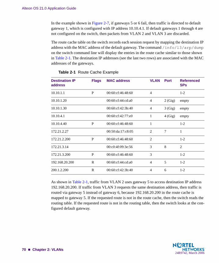
Alteon OS 21.0 Application Guide
In the example shown in Figure 2-7, if gateways 5 or 6 fail, then traffic is directed to default gateway 1, which is configured with IP address 10.10.4.1. If default gateways 1 through 4 are not configured on the switch, then packets from VLAN 2 and VLAN 3 are discarded.
The route cache table on the switch records each session request by mapping the destination IP address with the MAC address of the default gateway. The command /info/l3/arp/dump on the switch command line will display the entries in the route cache similar to those shown in Table 2-1. The destination IP addresses (see the last two rows) are associated with the MAC addresses of the gateways.
As shown in Table 2-1, traffic from VLAN 2 uses gateway 5 to access destination IP address 192.168.20.200. If traffic from VLAN 3 requests the same destination address, then traffic is routed via gateway 5 instead of gateway 6, because 192.168.20.200 in the route cache is mapped to gateway 5. If the requested route is not in the route cache, then the switch reads the routing table. If the requested route is not in the routing table, then the switch looks at the con-figured default gateway.
Table 2-1 Route Cache Example
Destination IP address
Flags MAC address VLAN Port Referenced SPs
10.10.1.1 P 00:60:cf:46:48:60 4 1-2
10.10.1.20 00:60:cf:44:cd:a0 4 2 (Gig) empty
10.10.1.30 00:60:cf:42:3b:40 4 3 (Gig) empty
10.10.4.1 00:60:cf:42:77:e0 1 4 (Gig) empty
10.10.4.40 P 00:60:cf:46:48:60 1 1-2
172.21.2.27 00:50:da:17:c8:05 2 7 1
172.21.2.200 P 00:60:cf:46:48:60 2 1-2
172.21.3.14 00:c0:4f:09:3e:56 3 8 2
172.21.3.200 P 00:60:cf:46:48:60 3 1-2
192.168.20.200 R 00:60:cf:44:cd:a0 4 5 1-2
200.1.2.200 R 00:60:cf:42:3b:40 4 6 1-2
70 Chapter 2: VLANs24R9742, March 2006

Alteon OS 21.0 Application Guide
Configuring the Local NetworkTo completely segregate VLAN traffic to its own default gateway, you can configure the local network addresses of the VLAN. This will ensure that all traffic from VLAN 2 is forwarded to gateway 5 and all traffic from VLAN 3 is forwarded to gateway 6.
Typically, the switch routes traffic based on the routes in the routing table. The routing table will contain an entry of the configured local network with the default gateway. The route cache will not contain the route entry. This configuration provides a more secure environment, but affects performance if the routing table is close to its maximum capacity.
Configuring Gateways per VLANFollow this procedure to configure the example shown in Figure 2-7 on page 69:
1. Assign an IP address for each router and client workstation.
2. Assign an IP interface for each subnet attached to the switch.
>> /cfg/l3/if 1 (Select IP interface 1 for gateway 5 & 6 subnet)
>> IP Interface 1# addr 10.10.1.1 (Assign IP address for interface 1)>> IP Interface 1# mask 255.255.255.0 (Assign mask for IF 1)>> IP Interface 1# vlan 4 (Assign VLAN 4 to IF 1)>> IP Interface 1# ../if 2 (Select IP interface 2 for gateway 1)>> IP Interface 2# addr 10.10.4.40 (Assign IP address for interface 2) >> IP Interface 2# mask 255.255.255.0 (Assign mask for IF 2)>> IP Interface 2# vlan 1 (Assign VLAN 1 to IF 2)>> IP Interface 2# ../if 3 (Select IP interface 3 for VLAN 2
subnet)>> IP Interface 3# addr 172.21.2.200 (Assign IP address for interface 3)>> IP Interface 3# mask 255.255.255.0 (Assign mask for IF 3)>> IP Interface 3# vlan 2 (Assign VLAN 2 to IF 3)>> IP Interface 3# ../if 4 (Select IP interface 4 for VLAN 3)
subnet)>> IP Interface 4# addr 172.21.3.200 (Assign IP address for interface 4)>> IP Interface 4# mask 255.255.255.0 (Assign mask for IF 4)>> IP Interface 4# vlan 3 (Assign VLAN 3 to IF 4)
Chapter 2: VLANs 7124R9742, March 2006

Alteon OS 21.0 Application Guide
3. Configure the default gateways.
Configuring gateways 5 and 6 for VLANs 2 and 3 respectively. Configure default gateway 1 for load balancing session requests and as backup when gateways 5 and 6 fail.
NOTE – The IP address for default gateways 1 to 4 must be unique. IP addresses for default gateways 5 to 254 can be set to the same IP address as the other gateways (including default gateway 1 to 4). For example, you can configure two default gateways with the same IP address for two different VLANs.
4. Add the VLANs to the gateways and enable them.
5. Apply and verify your configuration.
Examine the results under the gateway section. If any settings are incorrect, make the appropri-ate changes.
>> /cfg/l3/gw 5 (Select gateway 5)>> Default gateway 5# addr 10.10.1.20 (Assign IP address for gateway 5)>> Default gateway 5# ../gw 6 (Select default gateway 6)>> Default gateway 6# addr 10.10.1.30 (Assign IP address for gateway 6) >> Default gateway 6# ../gw 1 (Select default gateway 1)>> Default gateway 1# addr 10.10.4.1 (Assign IP address for gateway 1)
>> /cfg/l3/gw 5 (Select gateway 5)>> Default gateway 5# vlan 2 (Add VLAN 2 for default gateway 5)>> Default gateway 5# ena (Enable gateway 5)>> Default gateway 5# ../ gw 6 (Select gateway 6)>> Default gateway 6# vlan 3 (Add VLAN 3 for default gateway 6)>> Default gateway 6# ena (Enable gateway 6)>> Default gateway 6# ../gw 1 (Select default gateway 1)>> Default gateway 1# ena (Enable gateway 1 for all VLAN s)
>> Default gateway 1# ../cur (View current IP settings)
72 Chapter 2: VLANs24R9742, March 2006

Alteon OS 21.0 Application Guide
6. (Optional) Configure the local networks to ensure that the VLANs use the configured default gateways.
7. Apply and save your new configuration changes.
>> Layer 3# frwd/local (Select the local network Menu)>> IP Forwarding# add 10.10.0.0 (Specify the network for routers 1, 2,
& 3)>> IP Forwarding# mask 255.255.0.0 (Add the mask for the routers)>> IP Forwarding# add 172.21.2.0 (Specify the network for VLAN 2)>> IP Forwarding# mask 255.255.255.0 (Add the mask for VLAN 2 network)>> IP Forwarding# add 172.21.3.0 (Specify the network for VLAN 3)>> IP Forwarding# mask 255.255.255.0 (Add the mask for VLAN 3)
>> IP Forwarding# apply>> IP Forwarding# save
Chapter 2: VLANs 7324R9742, March 2006

Alteon OS 21.0 Application Guide
74 Chapter 2: VLANs24R9742, March 2006

CHAPTER 3Ports and Trunking
Trunk groups can provide super-bandwidth, multi-link connections between GbE Switch Mod-ules or other trunk-capable devices. A trunk group is a group of ports that act together, combin-ing their bandwidth to create a single, larger virtual link. This chapter provides configuration background and examples for trunking multiple ports together:
“ Overview” on this page
“Port Trunking Example” on page 79
“Configurable Trunk Hash Algorithm” on page 81
“Link Aggregation Control Protocol” on page 82
24R9742, March 200675

Alteon OS 21.0 Application Guide
OverviewWhen using port trunk groups between two switches, as shown in Figure 3-1, you can create a virtual link between the switches operating up to 4 Gig per second, depending on how many physical ports are combined. Each GbESM supports up to 13 trunk groups, consisting of one to four ports in each group. Both internal (INT1-INT14) and external ports (EXT1-EXT4) can become members of a trunk group.
Figure 3-1 Port Trunk Group
Trunk groups are also useful for connecting a GbE Switch Module to third-party devices that support link aggregation, such as Cisco routers and switches with EtherChannel technology (not ISL trunking technology) and Sun's Quad Fast Ethernet Adapter. Nortel Networks trunk group technology is compatible with these devices when they are configured manually.
OK
1
2
3
4
TX/RX
TX/RX
TX/RX
TX/RX
LINK
LINK
LINK
LINK
OK
1
2
3
4
TX/RX
TX/RX
TX/RX
TX/RX
LINK
LINK
LINK
LINK
BladeCenter
Aggregate port trunk
76 Chapter 3: Ports and Trunking24R9742, March 2006

Alteon OS 21.0 Application Guide
Statistical Load DistributionNetwork traffic is statistically distributed between the ports in a trunk group. The Alteon OS-powered switch uses the Layer 2 MAC address information present in each transmitted frame for determining load distribution.
Each packet’s particular combination of source and destination MAC addresses results in selecting one line in the trunk group for data transmission. If there are enough Layer 2 devices feeding the trunk lines, then traffic distribution becomes relatively even.
Built-In Fault ToleranceSince each trunk group is comprised of multiple physical links, the trunk group is inherently fault tolerant. As long as one connection between the switches is available, the trunk remains active.
Statistical load balancing is maintained whenever a port in a trunk group is lost or returned to service.
Before you configure static trunksWhen you create and enable a static trunk, the trunk members (switch ports) take on certain settings necessary for correct operation of the trunking feature.
Before you configure your trunk, you must consider these settings, along with specific config-uration rules, as follows:
1. Read the configuration rules provided in the section, “Trunk group configuration rules” on page 78.”
2. Determine which switch ports (up to four) are to become trunk members (the specific ports making up the trunk).
Ensure that the chosen switch ports are set to enabled, using the /cfg/port command.
Trunk member ports must have the same VLAN configuration.
3. Consider how the existing spanning tree will react to the new trunk configuration. See Chapter 4, “Spanning Tree Group” for spanning tree group configuration guidelines.
4. Consider how existing VLANs will be affected by the addition of a trunk.
Chapter 3: Ports and Trunking 7724R9742, March 2006

Alteon OS 21.0 Application Guide
Trunk group configuration rules The trunking feature operates according to specific configuration rules. When creating trunks, consider the following rules that determine how a trunk group reacts in any network topology:
All trunks must originate from one device, and lead to one destination device. For exam-ple, you cannot combine a link from Server 1 and a link from Server 2, into one trunk group.
Any physical switch port can belong to only one trunk group.
Trunking from third-party devices must comply with Cisco® EtherChannel® technology.
All trunk member ports must be assigned to the same VLAN configuration before the trunk can be enabled.
If you change the VLAN settings of any trunk member, you cannot apply the change until you change the VLAN settings of all trunk members.
When an active port is configured in a trunk, the port becomes a trunk member when you enable the trunk using the /cfg/l2/trunk/ena command. The spanning tree parameters for the port then change to reflect the new trunk settings.
All trunk members must be in the same Spanning Tree Group (STG) and can belong to only one Spanning Tree Group (STG). However if all ports are tagged, then all trunk ports can belong to multiple STGs.
If you change the Spanning Tree participation of any trunk member to enabled or dis-abled, the Spanning Tree participation of all members of that trunk changes similarly.
When a trunk is enabled, the trunk Spanning Tree participation setting takes precedence over that of any trunk member.
You cannot configure a trunk member as a monitor port in a port-mirroring configuration.
Trunks cannot be monitored by a monitor port; however, trunk members can be moni-tored.
To guarantee proper trunking behavior, all ports in static trunks must be configured for full-duplex mode (cfg/port x/gig/mode full).
78 Chapter 3: Ports and Trunking24R9742, March 2006

Alteon OS 21.0 Application Guide
Port Trunking ExampleIn the example below, three ports are trunked between two switches.
Figure 3-2 Port Trunk Group Configuration Example
Prior to configuring each switch in the above example, you must connect to the appropriate switch’s Command Line Interface (CLI) as the administrator.
NOTE – For details about accessing and using any of the menu commands described in this example, see the Alteon OS Command Reference.
Alteon Application Switch
BladeCenter
GbE SwitchModule
Trunk 3: Ports 2, 12, and 22
Trunk 1: Ports EXT2, EXT3, and EXT 4
Chapter 3: Ports and Trunking 7924R9742, March 2006

Alteon OS 21.0 Application Guide
1. Connect the switch ports that will be involved in the trunk group.
2. Follow these steps on the GbESM:
(a) Define a trunk group.
(b)Apply and verify the configuration.
Examine the resulting information. If any settings are incorrect, make appropriate changes.
(c) Save your new configuration changes.
3. Repeat the process on the other switch.
Trunk group 1 (on the GbESM) is now connected to trunk group 3 (on Alteon Application Switch).
NOTE – In this example, a GbE Switch Module and an application switch are used. If a third-party device supporting link aggregation is used (such as Cisco routers and switches with EtherChannel technology or Sun's Quad Fast Ethernet Adapter), trunk groups on the third-party device should be configured manually. Connection problems could arise when using automatic trunk group negotiation on the third-party device.
>> # /cfg/l2/trunk 1 (Select trunk group 1)>> Trunk group 1# add EXT2 (Add port EXT2 to trunk group 1)>> Trunk group 1# add EXT3 (Add port EXT3 to trunk group 1)>> Trunk group 1# add EXT4 (Add port EXT4 to trunk group 1)>> Trunk group 1# ena (Enable trunk group 1)
>> Trunk group 1# apply (Make your changes active)>> Trunk group 1# cur (View current trunking configuration)
>> Trunk group 1# save (Save for restore after reboot)
>> # /cfg/l2/trunk 3 (Select trunk group 3)>> Trunk group 3# add 2 (Add port 2 to trunk group 3)>> Trunk group 3# add 12 (Add port 12 to trunk group 3)>> Trunk group 3# add 22 (Add port 22 to trunk group 3)>> Trunk group 3# ena (Enable trunk group 3)>> Trunk group 3# apply (Make your changes active)>> Trunk group 3# cur (View current trunking configuration)>> Trunk group 3# save (Save for restore after reboot)
80 Chapter 3: Ports and Trunking24R9742, March 2006
Alteon OS 21.0 Application Guide
4. Examine the trunking information on each switch.
Information about each port in each configured trunk group is displayed. Make sure that trunk groups consist of the expected ports and that each port is in the expected state.
The following restrictions apply:
Any physical switch port can belong to only one trunk group.
Up to four ports can belong to the same trunk group.
Best performance is achieved when all ports in any given trunk group are configured for the same speed.
Trunking from third-party devices must comply with Cisco® EtherChannel® technology.
Configurable Trunk Hash AlgorithmThis feature allows you to configure the particular parameters for the GbESM Trunk Hash algorithm instead of having to utilize the defaults. You can configure new default behavior for Layer 2 traffic and Layer 3 traffic using the CLI menu cfg/l2/thash. You can select a minimum of one or a maximum of two parameters to create one of the following configura-tions:
Source IP (SIP)
Destination IP (DIP)
Source MAC (SMAC)
Destination MAC (DMAC)
Source IP (SIP) + Destination IP (DIP)
Source MAC (SMAC) + Destination MAC (DMAC)
Source MAC (SMAC) + Source IP (SIP)
Source MAC (SMAC) + Destination IP (DIP)
>> /info/l2/trunk (View trunking information)
Chapter 3: Ports and Trunking 8124R9742, March 2006

Alteon OS 21.0 Application Guide
Link Aggregation Control ProtocolLink Aggregation Control Protocol (LACP) is an IEEE 802.3ad standard for grouping several physical ports into one logical port (known as a dynamic trunk group or Link Aggregation group) with any device that supports the standard. Please refer to IEEE 802.3ad-2002 for a full description of the standard.
The 802.3ad standard allows standard Ethernet links to form a single Layer 2 link using the Link Aggregation Control Protocol (LACP). Link aggregation is a method of grouping physi-cal link segments of the same media type and speed in full duplex, and treating them as if they were part of a single, logical link segment. If a link in a LACP trunk group fails, traffic is reas-signed dynamically to the remaining link/s of the dynamic trunk group.
NOTE – LACP implementation in Alteon OS 21.0 does not support the Churn machine, an option used to detect if the port is operable within a bounded time period between the actor and the partner. Only the Market Responder is implemented, and there is no marker protocol generator.
A port’s Link Aggregation Identifier (LAG ID) determines how the port can be aggregated. The Link Aggregation ID (LAG ID) is constructed mainly from the system ID and the port’s admin key, as follows:
System ID is an integer value based on the switch’s MAC address and the system priority assigned in the CLI.
Admin keyA port’s Admin key is an integer value (1 - 65535) that you can configure in the CLI. Each GbESM port that participates in the same LACP trunk group must have the same admin key value. The Admin key is local significant, which means the partner switch does not need to use the same Admin key value.
82 Chapter 3: Ports and Trunking24R9742, March 2006
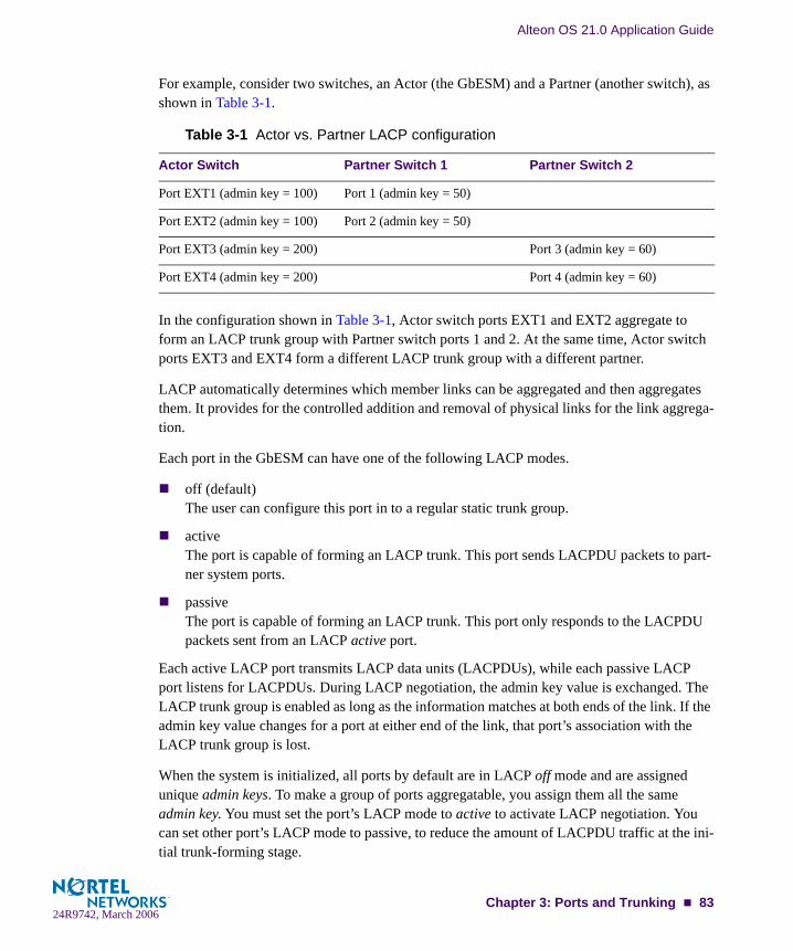
Alteon OS 21.0 Application Guide
For example, consider two switches, an Actor (the GbESM) and a Partner (another switch), as shown in Table 3-1.
In the configuration shown in Table 3-1, Actor switch ports EXT1 and EXT2 aggregate to form an LACP trunk group with Partner switch ports 1 and 2. At the same time, Actor switch ports EXT3 and EXT4 form a different LACP trunk group with a different partner.
LACP automatically determines which member links can be aggregated and then aggregates them. It provides for the controlled addition and removal of physical links for the link aggrega-tion.
Each port in the GbESM can have one of the following LACP modes.
off (default)The user can configure this port in to a regular static trunk group.
activeThe port is capable of forming an LACP trunk. This port sends LACPDU packets to part-ner system ports.
passiveThe port is capable of forming an LACP trunk. This port only responds to the LACPDU packets sent from an LACP active port.
Each active LACP port transmits LACP data units (LACPDUs), while each passive LACP port listens for LACPDUs. During LACP negotiation, the admin key value is exchanged. The LACP trunk group is enabled as long as the information matches at both ends of the link. If the admin key value changes for a port at either end of the link, that port’s association with the LACP trunk group is lost.
When the system is initialized, all ports by default are in LACP off mode and are assigned unique admin keys. To make a group of ports aggregatable, you assign them all the same admin key. You must set the port’s LACP mode to active to activate LACP negotiation. You can set other port’s LACP mode to passive, to reduce the amount of LACPDU traffic at the ini-tial trunk-forming stage.
Table 3-1 Actor vs. Partner LACP configuration
Actor Switch Partner Switch 1 Partner Switch 2
Port EXT1 (admin key = 100) Port 1 (admin key = 50)
Port EXT2 (admin key = 100) Port 2 (admin key = 50)
Port EXT3 (admin key = 200) Port 3 (admin key = 60)
Port EXT4 (admin key = 200) Port 4 (admin key = 60)
Chapter 3: Ports and Trunking 8324R9742, March 2006

Alteon OS 21.0 Application Guide
Use the /info/l2/trunk command or the /info/l2/lacp/dump command to check whether the ports are trunked.
Configuring LACPUse the following procedure to configure LACP for port EXT1 and port EXT2 to participate in link aggregation.
1. Set the LACP mode on port EXT1.
2. Define the admin key on port EXT1. Only ports with the same admin key can form a LACP trunk group.
3. Set the LACP mode on port EXT2.
4. Define the admin key on port EXT2.
5. Apply and verify the configuration.
6. Save your new configuration changes.
>> # /cfg/l2/lacp/port EXT1 (Select port EXT1)>> LACP port EXT1# mode active (Set port EXT1 to LACP active mode)
>> LACP port EXT1# adminkey 100 (Set port EXT1 adminkey to 100)Current LACP port adminkey: 17New pending LACP port adminkey: 100
>> # /cfg/l2/lacp/port EXT2 (Select port EXT2)>> LACP port EXT2# mode active (Set port EXT2 to LACP active mode)
>> LACP port EXT2# adminkey 100 (Set port EXT2 adminkey to 100)Current LACP port adminkey: 18New pending LACP port adminkey: 100
>> LACP port EXT2# apply (Make your changes active)>> LACP port EXT2# cur (View current trunking configuration)
>> LACP port EXT2# save (Save for restore after reboot)
84 Chapter 3: Ports and Trunking24R9742, March 2006
CHAPTER 4Spanning Tree Group
When multiple paths exist on a network, Spanning Tree Group (STG) configures the network so that a switch uses only the most efficient path. The following topics are discussed in this chapter:
“Overview” on page 86
“Bridge Protocol Data Units (BPDUs)” on page 87
“Multiple Spanning Trees” on page 90
24R9742, March 200685
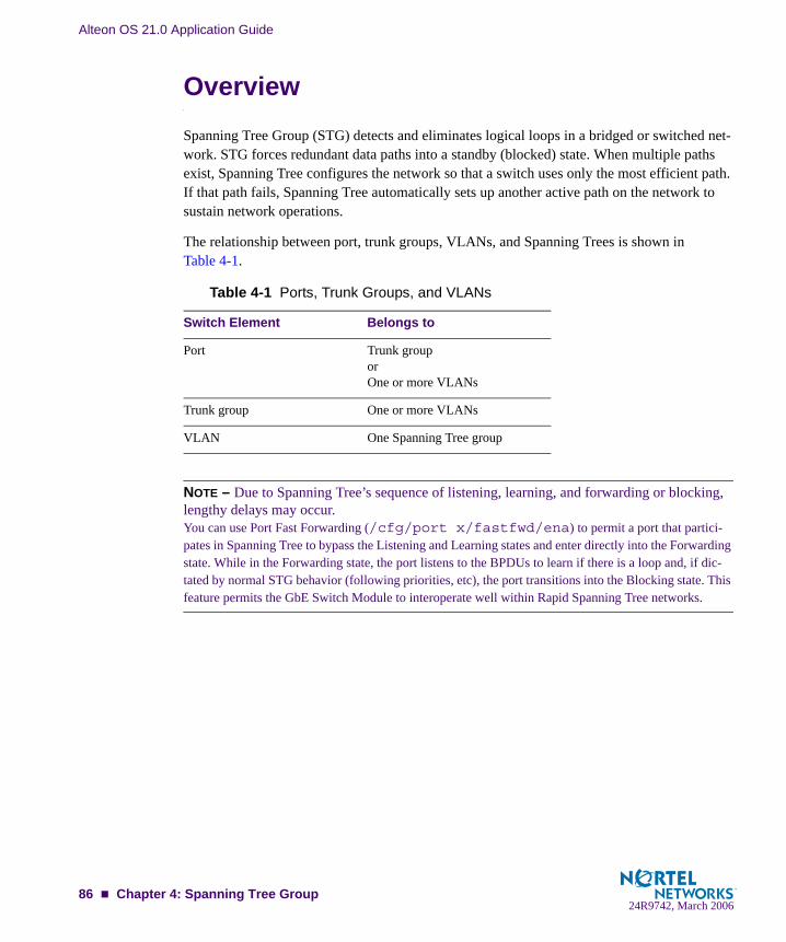
Alteon OS 21.0 Application Guide
OverviewSpanning Tree Group (STG) detects and eliminates logical loops in a bridged or switched net-work. STG forces redundant data paths into a standby (blocked) state. When multiple paths exist, Spanning Tree configures the network so that a switch uses only the most efficient path. If that path fails, Spanning Tree automatically sets up another active path on the network to sustain network operations.
The relationship between port, trunk groups, VLANs, and Spanning Trees is shown inTable 4-1.
NOTE – Due to Spanning Tree’s sequence of listening, learning, and forwarding or blocking, lengthy delays may occur. You can use Port Fast Forwarding (/cfg/port x/fastfwd/ena) to permit a port that partici-pates in Spanning Tree to bypass the Listening and Learning states and enter directly into the Forwarding state. While in the Forwarding state, the port listens to the BPDUs to learn if there is a loop and, if dic-tated by normal STG behavior (following priorities, etc), the port transitions into the Blocking state. This feature permits the GbE Switch Module to interoperate well within Rapid Spanning Tree networks.
Table 4-1 Ports, Trunk Groups, and VLANs
Switch Element Belongs to
Port Trunk grouporOne or more VLANs
Trunk group One or more VLANs
VLAN One Spanning Tree group
86 Chapter 4: Spanning Tree Group24R9742, March 2006

Alteon OS 21.0 Application Guide
Bridge Protocol Data Units (BPDUs)To create a Spanning Tree, the switch generates a configuration Bridge Protocol Data Unit (BPDU), which it then forwards out of its ports. All switches in the Layer 2 network participat-ing in the Spanning Tree gather information about other switches in the network through an exchange of BPDUs.
A BPDU is a 64-byte packet that is sent out at a configurable interval, which is typically set for two seconds. The BPDU is used to establish a path, much like a “hello” packet in IP routing. BPDUs contain information about the transmitting bridge and its ports, including bridge and MAC addresses, bridge priority, port priority, and path cost. If the ports are tagged, each port sends out a special BPDU containing the tagged information.
The generic action of a switch on receiving a BPDU is to compare the received BPDU to its own BPDU that it will transmit. If the received BPDU is better than its own BPDU, it will replace its BPDU with the received BPDU. Then, the switch adds its own bridge ID number and increments the path cost of the BPDU. The switch uses this information to block any nec-essary ports.
Determining the Path for Forwarding BPDUsWhen determining which port to use for forwarding and which port to block, the GbE Switch Module uses information in the BPDU, including each bridge priority ID. A technique based on the “lowest root cost” is then computed to determine the most efficient path for forwarding.
Bridge PriorityThe bridge priority parameter controls which bridge on the network is the STG root bridge. To make one switch the root bridge, configure the bridge priority lower than all other switches and bridges on your network. The lower the value, the higher the bridge priority. The bridge prior-ity is configured using the /cfg/l2/stg x/brg/prior command in the CLI.
Port PriorityThe port priority helps determine which bridge port becomes the designated port. In a network topology that has multiple bridge ports connected to a single segment, the port with the lowest port priority becomes the designated port for the segment. The port priority is configured using the /cfg/l2/stg x/port x/prior command in the CLI.
Chapter 4: Spanning Tree Group 8724R9742, March 2006

Alteon OS 21.0 Application Guide
Port Path CostThe port path cost assigns lower values to high-bandwidth ports, such as Gigabit Ethernet, to encourage their use. The cost of a port also depends on whether the port operates at full-duplex (lower cost) or half-duplex (higher cost). For example, if a 100-Mbps (Fast Ethernet) link has a “cost” of 10 in half-duplex mode, it will have a cost of 5 in full-duplex mode. The objective is to use the fastest links so that the route with the lowest cost is chosen. A value of 0 indicates that the default cost will be computed for an auto-negotiated link speed.
Spanning Tree Group configuration guidelinesThis section provides important information on configuring Spanning Tree Groups (STGs):
Adding a VLAN to a Spanning Tree GroupIf no VLANs exist beyond the default VLAN 1 see “Creating a VLAN” on page 88 for information on adding ports to VLANs.
Add the VLAN to the STG using the /cfg/l2/stg <stg-#>/add <vlan-number> command.
NOTE – To ensure proper operation with switches that use Cisco Per VLAN Spanning Tree (PVST+), you must either: create a separate STG for each VLAN, ormanually add all associated VLANs into a single STG.
Creating a VLANWhen you create a VLAN, that VLAN automatically belongs to STG 1, the default STG. If you want the VLAN in another STG, you must move the VLAN by assigning it to another STG.
Move a newly created VLAN to an existing STG by following this order:
Create the VLAN
Add the VLAN to an existing STG
You cannot delete or move VLAN 1 from STG 1.
88 Chapter 4: Spanning Tree Group24R9742, March 2006
Alteon OS 21.0 Application Guide
VLANs must be contained within a single STG; a VLAN cannot span multiple STGs. By confining VLANs within a single STG, you avoid problems with spanning tree blocking ports and causing a loss of connectivity within the VLAN. When a VLAN spans multiple switches, the VLAN must be within the same Spanning Tree Group (have the same STG ID) across all the switches.
If ports are tagged, all trunked ports can belong to multiple STGs.
A port that is not a member of any VLAN cannot be added to any STG. The port must be added to a VLAN, and that VLAN added to the desired STG.
Rules for VLAN Tagged portsTagged ports can belong to more than one STG, but untagged ports can belong to only one STG.
When a tagged port belongs to more than one STG, the egress BPDUs are tagged to distin-guish the BPDUs of one STG from those of another STG.
An untagged port cannot span multiple STGs.
Adding and removing ports from STGsWhen you add a port to a VLAN that belongs to an STG, the port is also added to the STG. However, if the port you are adding is an untagged port and is already a member of an STG, that port will not be added to an additional STG because an untagged port cannot belong to more that one STG.
For example, assume that VLAN 1 belongs to STG 1. You add an untagged port, port 1, that does not belong to any STG to VLAN 1, and port 1 will become part of STG 1.
If you add untagged port 5 (which is a member to STG 2) to STG 1, the switch will prompt you to change the PVID from 2 to 1:
When you remove a port from VLAN that belongs to an STG, that port will also be removed from the STG. However, if that port belongs to another VLAN in the same STG, the port remains in the STG.
As an example, assume that port 1 belongs to VLAN 1, and VLAN 1 belongs to STG 1. When you remove port 1 from VLAN 1, port 1 is also removed from STG 1.
However, if port 1 belongs to both VLAN 1 and VLAN 2 and both VLANs belong to STG 1, removing port 1 from VLAN 1 does not remove port 1 from STG 1 because VLAN 2 is still a member of STG 1.
"Port 5 is an UNTAGGED port and its current PVID is 2.Confirm changing PVID from 2 to 1 [y/n]:" y
Chapter 4: Spanning Tree Group 8924R9742, March 2006

Alteon OS 21.0 Application Guide
An STG cannot be deleted, only disabled. If you disable the STG while it still contains VLAN members, Spanning Tree will be off on all ports belonging to that VLAN.
The relationship between port, trunk groups, VLANs, and Spanning Trees is shown inTable 4-1.
Multiple Spanning TreesEach GbE Switch Module supports a maximum of 32 Spanning Tree Groups (STGs). Multiple STGs provide multiple data paths, which can be used for load-balancing and redundancy.
You enable load balancing between two GbE Switch Modules using multiple STGs by config-uring each path with a different VLAN and then assigning each VLAN to a separate STG. Each STG is independent. Each STG sends its own Bridge Protocol Data Units (BPDUs), and each STG must be independently configured.
The STG, or bridge group, forms a loop-free topology that includes one or more virtual LANs (VLANs). The switch supports 32 STGs running simultaneously. The default STG 1 may con-tain an unlimited number of VLANs. All other STGs 2-32 may contain one VLAN each.
Default Spanning Tree configurationIn the default configuration, a single STG with the ID of 1 includes all non-management ports on the switch. It is called the default STG. Although ports can be added to or deleted from the default STG, the default STG (STG 1) itself cannot be deleted from the system. Also you can-not delete the default VLAN (VLAN 1) from STG 1.
All other STGs, except the default STG and the management STG (32), are empty and VLANs must be added by the user. However, you cannot assign ports directly to an STG. Add ports to a VLAN and add the VLAN to the STG. Each STG is enabled by default, and assigned an ID number from 2 to 32.
Table 4-2 Ports, Trunk Groups, and VLANs
Switch Element Belongs to
Port Trunk grouporOne or more VLANs
Trunk group One or more VLANs
VLAN (non-default) One Spanning Tree group
90 Chapter 4: Spanning Tree Group24R9742, March 2006

Alteon OS 21.0 Application Guide
Why Do We Need Multiple Spanning Trees?Figure 4-1 shows a simple example of why we need multiple Spanning Trees. Two VLANs, VLAN 1 and VLAN 100 exist between application switch A and GbE Switch Module B. If you have a single Spanning Tree Group, the switches see an apparent loop, and one VLAN may become blocked, affecting connectivity, even though no actual loop exists.
If VLAN 1 and VLAN 100 belong to different Spanning Tree Groups, then the two instances of Spanning Tree separate the topology without forming a loop. Both VLANs can forward packets between the switches without losing connectivity.
Figure 4-1 Using Multiple Instances of Spanning Tree Group
Switch-Centric Spanning Tree GroupIn Figure 4-2 on page 92, VLAN 2 is shared by application switch A and GbE Switch Module B on ports 8 and 17 respectively. Application Switch A identifies VLAN 2 in Spanning Tree Group 2 and GbE Switch Module B identifies VLAN 2 in Spanning Tree Group 1. Spanning Tree Group is switch-centric—it is used to identify the VLANs participating in the Spanning Tree Groups. The Spanning Tree Group ID is not transmitted in the BPDU. Each Spanning Tree decision is based on the configuration of that switch.
BladeCenter
GbE Switch Module BGbE Switch Module B
Chapter 4: Spanning Tree Group 9124R9742, March 2006
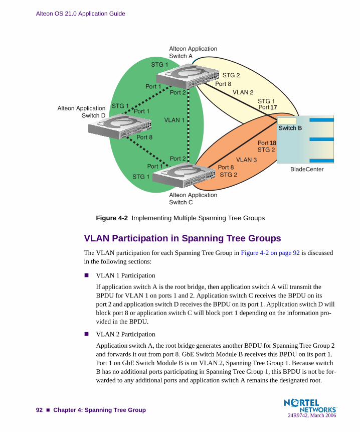
Alteon OS 21.0 Application Guide
Figure 4-2 Implementing Multiple Spanning Tree Groups
VLAN Participation in Spanning Tree GroupsThe VLAN participation for each Spanning Tree Group in Figure 4-2 on page 92 is discussed in the following sections:
VLAN 1 Participation
If application switch A is the root bridge, then application switch A will transmit the BPDU for VLAN 1 on ports 1 and 2. Application switch C receives the BPDU on its port 2 and application switch D receives the BPDU on its port 1. Application switch D will block port 8 or application switch C will block port 1 depending on the information pro-vided in the BPDU.
VLAN 2 Participation
Application switch A, the root bridge generates another BPDU for Spanning Tree Group 2 and forwards it out from port 8. GbE Switch Module B receives this BPDU on its port 1. Port 1 on GbE Switch Module B is on VLAN 2, Spanning Tree Group 1. Because switch B has no additional ports participating in Spanning Tree Group 1, this BPDU is not be for-warded to any additional ports and application switch A remains the designated root.
BladeCenter
Switch BSwitch B
1717
1818
92 Chapter 4: Spanning Tree Group24R9742, March 2006

Alteon OS 21.0 Application Guide
VLAN 3 Participation
For VLAN 3 you can have GbE Switch Module B or application switch C to be the root bridge. If switch B is the root bridge for VLAN 3, Spanning Tree Group 2, then switch B transmits the BPDU out from port 2. Application switch C receives this BPDU on port 8 and is identified as participating in VLAN 3, Spanning Tree Group 2. Since application switch C has no additional ports participating in Spanning Tree Group 2, this BPDU is not forwarded to any additional ports and GbE Switch Module B remains the designated root.
Configuring Multiple Spanning Tree GroupsThis configuration shows how to configure the three instances of Spanning Tree Groups on the switches A, B, C, and D illustrated in Figure 4-2 on page 92.
By default Spanning Trees 2-15 are empty, and Spanning Tree Group 1 contains all configured VLANs until individual VLANs are explicitly assigned to other Spanning Tree Groups. You can have only one VLAN per Spanning Tree Group except for Spanning Tree Group 1.
1. Configure the following on application switch A:
Add port 8 to VLAN 2 and define Spanning Tree Group 2 for VLAN 2.
VLAN 2 is automatically removed from Spanning Tree Group 1.
2. Configure the following on GbE Switch Module B:
Add port 1 to VLAN 2, port 2 to VLAN 3 and define Spanning Tree Groups 2 for VLAN 3.
VLAN 3 is automatically removed from Spanning Tree Group 1, and VLAN 2 remains in Spanning Tree Group 1 by default.
>> # /cfg/l2/vlan2 (Select VLAN 2 menu)>> VLAN 2# add 8 (Add port 8)>> VLAN 2# ../stg 2 (Select Spanning Tree Group 2)>> Spanning Tree Group 2# add 2 (Add VLAN 2)
>> # /cfg/l2/vlan2 (Select VLAN 2 menu)>> VLAN 2# add 17 (Add port 17)>> VLAN 2# ../vlan3 (Select VLAN 3 menu)>> VLAN 3# add 18 (Add port 18)>> VLAN 3# ../stg 2 (Select Spanning Tree Group 2)>> Spanning Tree Group 2# add 3 (Add VLAN 3)
Chapter 4: Spanning Tree Group 9324R9742, March 2006

Alteon OS 21.0 Application Guide
NOTE – Each instance of Spanning Tree Group is enabled by default.
3. Configure the following on application switch C:
Add port 8 to VLAN 3 and define Spanning Tree Group 3 for VLAN 3.
VLAN 3 is automatically removed from Spanning Tree Group 1 and by default VLAN 2 remains in Spanning Tree Group 1.
NOTE – Application Switch D does not require any special configuration for multiple Span-ning Trees, because it is configured for the default Spanning Tree Group (STG 1) only.
Port Fast ForwardingPort Fast Forwarding permits a port that participates in Spanning Tree to bypass the Listening and Learning states and enter directly into the Forwarding state. While in the Forwarding state, the port listens to the BPDUs to learn if there is a loop and, if dictated by normal STG behavior (following priorities, etc.), the port transitions into the Blocking state.
This feature permits the GbE Switch Module to interoperate well within Rapid Spanning Tree (RSTP) networks.
Configuring Port Fast ForwardingUse the following CLI commands to enable Port Fast Forwarding on an external port.
>> # /cfg/l2/vlan3 (Select VLAN 3 menu)>> VLAN 3# add 8 (Add port 8)>> VLAN 3# ../stg 2 (Select Spanning Tree Group 2)>> Spanning Tree Group 2# add 3 (Add VLAN 3)
>> # /cfg/port ext1 (Select port EXT 1)>> Port EXT1# fastfwd ena (Enable Port Fast Forwarding)>> Port EXT1# apply (Make your changes active)>> Port EXT1# save (Save for restore after reboot)
94 Chapter 4: Spanning Tree Group24R9742, March 2006
Alteon OS 21.0 Application Guide
Fast Uplink Convergence
Fast Uplink Convergence enables the GbESM to quickly recover from the failure of the pri-mary link or trunk group in a Layer 2 network using Spanning Tree Protocol. Normal recovery can take as long as 50 seconds, while the backup link transitions from Blocking to Listening to Learning and then Forwarding states. With Fast Uplink Convergence enabled, the GbESM immediately places the secondary path into Forwarding state, and sends multicasts of addresses in the forwarding database (FDB) and ARP table over the secondary link so that upstream switches can learn the new path.
Configuration GuidelinesWhen you enable Fast Uplink Convergence, Alteon OS automatically makes the following configuration changes:
Increases the STG priority of the GbESM so that it does not become the root switch.
Increases the cost of all of the external ports by 3000, across all VLANs and Spanning Tree Groups. This ensures that traffic never flows through the GbESM to get to another switch unless there is no other path.
These changes are reversed if the feature is disabled.
Configuring Fast Uplink ConvergenceUse the following CLI commands to enable Fast Uplink Convergence on an external port.
>> # /cfg/l2/upfast ena (Enable Fast Uplink convergence)>> Layer 2# apply (Make your changes active)>> Layer 2# save (Save for restore after reboot)
Chapter 4: Spanning Tree Group 9524R9742, March 2006

Alteon OS 21.0 Application Guide
96 Chapter 4: Spanning Tree Group24R9742, March 2006

Part 2: IP RoutingThis section discusses Layer 3 switching functions. In addition to switching traffic at near line rates, the application switch can perform multi-protocol routing. This section discusses basic routing and advanced routing protocols:
Basic Routing
Routing Information Protocol (RIP) 1
IGMP Snooping
Border Gateway Protocol (BGP)
Open Shortest Path First (OSPF)
24R9742, March 2006

Alteon OS 21.0 Application Guide
98 : IP Routing24R9742, March 2006
CHAPTER 5Basic IP Routing
This chapter provides configuration background and examples for using the GbE Switch Mod-ule to perform IP routing functions. The following topics are addressed in this chapter:
“IP Routing Benefits” on page 100
“Routing Between IP Subnets” on page 100
“Example of Subnet Routing” on page 103
“Defining IP Address Ranges for the Local Route Cache” on page 107
“Configuring Static Multicast Routes” on page 108
“Dynamic Host Configuration Protocol” on page 108
24R9742, March 200699
Alteon OS 21.0 Application Guide
IP Routing BenefitsThe GbE Switch Module uses a combination of configurable IP switch interfaces and IP rout-ing options. The switch IP routing capabilities provide the following benefits:
Connects the server IP subnets to the rest of the backbone network.
Performs server load balancing (using both Layer 3 and Layer 4 switching in combina-tion) to server subnets that are separate from backbone subnets.
Provides another means to invisibly introduce Jumbo frame technology into the server-switched network by automatically fragmenting UDP Jumbo frames when routing to non-Jumbo frame VLANs or subnets.
Provides the ability to route IP traffic between multiple Virtual Local Area Networks (VLANs) configured on the switch.
Routing Between IP SubnetsThe physical layout of most corporate networks has evolved over time. Classic hub/router topologies have given way to faster switched topologies, particularly now that switches are increasingly intelligent. GbE Switch Modules are intelligent and fast enough to perform rout-ing functions on a par with wire speed Layer 2 switching.
The combination of faster routing and switching in a single device provides another service—it allows you to build versatile topologies that account for legacy configurations.
100 Chapter 5: Basic IP Routing24R9742, March 2006

Alteon OS 21.0 Application Guide
For example, consider the following topology migration:
Figure 5-1 The Router Legacy Network
In this example, a corporate campus has migrated from a router-centric topology to a faster, more powerful, switch-based topology. As is often the case, the legacy of network growth and redesign has left the system with a mix of illogically distributed subnets.
This is a situation that switching alone cannot cure. Instead, the router is flooded with cross-subnet communication. This compromises efficiency in two ways:
Routers can be slower than switches. The cross-subnet side trip from the switch to the router and back again adds two hops for the data, slowing throughput considerably.
Traffic to the router increases, increasing congestion.
Even if every end-station could be moved to better logical subnets (a daunting task), competi-tion for access to common server pools on different subnets still burdens the routers.
InternetInternetInternetInternet
BladeCenter
GbE Switch Module
Chapter 5: Basic IP Routing 10124R9742, March 2006

Alteon OS 21.0 Application Guide
This problem is solved by using GbE Switch Modules with built-in IP routing capabilities. Cross-subnet LAN traffic can now be routed within the switches with wire speed Layer 2 switching performance. This not only eases the load on the router but saves the network administrators from reconfiguring each and every end-station with new IP addresses.
Take a closer look at the BladeCenter’s GbE Switch Module in the following configuration example:
Figure 5-2 Switch-Based Routing Topology
The GbE Switch Module connects the Gigabit Ethernet and Fast Ethernet trunks from various switched subnets throughout one building. Common servers are placed on another subnet attached to the switch. A primary and backup router are attached to the switch on yet another subnet.
Without Layer 3 IP routing on the switch, cross-subnet communication is relayed to the default gateway (in this case, the router) for the next level of routing intelligence. The router fills in the necessary address information and sends the data back to the switch, which then relays the packet to the proper destination subnet using Layer 2 switching.
With Layer 3 IP routing in place on the GbE Switch Module, routing between different IP sub-nets can be accomplished entirely within the switch. This leaves the routers free to handle inbound and outbound traffic for this group of subnets.
BladeCenterBladeCenter
Server Subnet: 206.30.15.2-254206.30.15.2-254
IF #1IF #1
IF #2IF #2 IF #3IF #3
IF #4IF #4GbESM
102 Chapter 5: Basic IP Routing24R9742, March 2006

Alteon OS 21.0 Application Guide
To make implementation even easier, UDP Jumbo frame traffic is automatically fragmented to regular Ethernet frame sizes when routing to non-Jumbo frame VLANS or subnets. This auto-matic frame conversion allows servers to communicate using Jumbo frames, all transparently to the user.
Example of Subnet RoutingPrior to configuring, you must be connected to the switch Command Line Interface (CLI) as the administrator.
NOTE – For details about accessing and using any of the menu commands described in this example, see the Alteon OS Command Reference.
1. Assign an IP address (or document the existing one) for each real server, router, and cli-ent workstation.
In the example topology in Figure 5-2 on page 102, the following IP addresses are used:
2. Assign an IP interface for each subnet attached to the switch.
Since there are four IP subnets connected to the switch, four IP interfaces are needed:
Table 5-1 Subnet Routing Example: IP Address Assignments
Subnet Devices IP Addresses
1 Primary and Secondary Default Routers 205.21.17.1 and 205.21.17.2
2 First Floor Client Workstations 100.20.10.2-254
3 Second Floor Client Workstations 131.15.15.2-254
4 Common Servers 206.30.15.2-254
Table 5-2 Subnet Routing Example: IP Interface Assignments
Interface Devices IP Interface Address
IF 1 Primary and Secondary Default Routers 205.21.17.3
IF 2 First Floor Client Workstations 100.20.10.1
IF 3 Second Floor Client Workstations 131.15.15.1
IF 4 Common Servers 206.30.15.1
Chapter 5: Basic IP Routing 10324R9742, March 2006
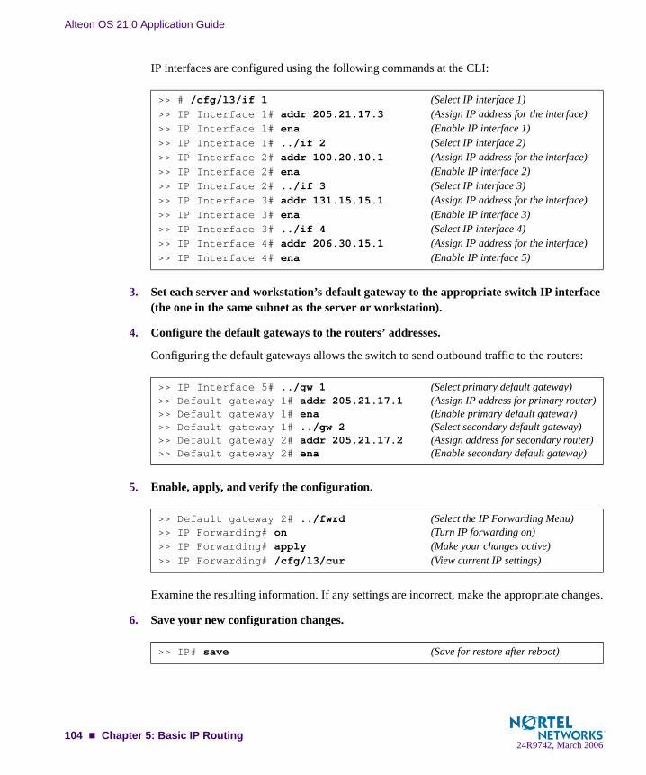
Alteon OS 21.0 Application Guide
IP interfaces are configured using the following commands at the CLI:
3. Set each server and workstation’s default gateway to the appropriate switch IP interface (the one in the same subnet as the server or workstation).
4. Configure the default gateways to the routers’ addresses.
Configuring the default gateways allows the switch to send outbound traffic to the routers:
5. Enable, apply, and verify the configuration.
Examine the resulting information. If any settings are incorrect, make the appropriate changes.
6. Save your new configuration changes.
>> # /cfg/l3/if 1 (Select IP interface 1)>> IP Interface 1# addr 205.21.17.3 (Assign IP address for the interface)>> IP Interface 1# ena (Enable IP interface 1)>> IP Interface 1# ../if 2 (Select IP interface 2)>> IP Interface 2# addr 100.20.10.1 (Assign IP address for the interface)>> IP Interface 2# ena (Enable IP interface 2)>> IP Interface 2# ../if 3 (Select IP interface 3)>> IP Interface 3# addr 131.15.15.1 (Assign IP address for the interface)>> IP Interface 3# ena (Enable IP interface 3)>> IP Interface 3# ../if 4 (Select IP interface 4)>> IP Interface 4# addr 206.30.15.1 (Assign IP address for the interface)>> IP Interface 4# ena (Enable IP interface 5)
>> IP Interface 5# ../gw 1 (Select primary default gateway)>> Default gateway 1# addr 205.21.17.1 (Assign IP address for primary router)>> Default gateway 1# ena (Enable primary default gateway)>> Default gateway 1# ../gw 2 (Select secondary default gateway)>> Default gateway 2# addr 205.21.17.2 (Assign address for secondary router) >> Default gateway 2# ena (Enable secondary default gateway)
>> Default gateway 2# ../fwrd (Select the IP Forwarding Menu)>> IP Forwarding# on (Turn IP forwarding on)>> IP Forwarding# apply (Make your changes active)>> IP Forwarding# /cfg/l3/cur (View current IP settings)
>> IP# save (Save for restore after reboot)
104 Chapter 5: Basic IP Routing24R9742, March 2006

Alteon OS 21.0 Application Guide
Using VLANs to Segregate Broadcast DomainsIn the previous example, devices that share a common IP network are all in the same broadcast domain. If you want to limit the broadcasts on your network, you could use VLANs to create distinct broadcast domains. For example, as shown in the following procedure, you could cre-ate one VLAN for the client trunks, one for the routers, and one for the servers.
In this example, you are adding to the previous configuration.
1. Determine which switch ports and IP interfaces belong to which VLANs.
The following table adds port and VLAN information:
2. Add the switch ports to their respective VLANs.
The VLANs shown in Table 5-3 are configured as follows:
Table 5-3 Subnet Routing Example: Optional VLAN Ports
VLAN Devices IP Interface Switch Port VLAN #
1 First Floor Client Workstations 2 EXT1 1
Second Floor Client Workstations 3 EXT2 1
2 Primary Default Router 1 EXT3 2
Secondary Default Router 1 EXT4 2
3 Common Servers 1 4 INT5 3
Common Servers 2 4 INT6 3
>> # /cfg/l2/vlan 1 (Select VLAN 1)>> VLAN 1# add port EXT1 (Add port for 1st floor to VLAN 1)>> VLAN 1# add port EXT2 (Add port for 2nd floor to VLAN 1)>> VLAN 1# ena (Enable VLAN 1)>> VLAN 1# ../VLAN 2 (Select VLAN 2)>> VLAN 2# add port EXT3 (Add port for default router 1)>> VLAN 2# add port EXT4 (Add port for default router 2)>> VLAN 2# ena (Enable VLAN 2)>> VLAN 2# ../VLAN 3 (Add port for default router 3)>> VLAN 3# add port INT5 (Select VLAN 3)>> VLAN 3# add port INT6 (Select port for common server 1)>> VLAN 3# ena (Enable VLAN 3)
Chapter 5: Basic IP Routing 10524R9742, March 2006
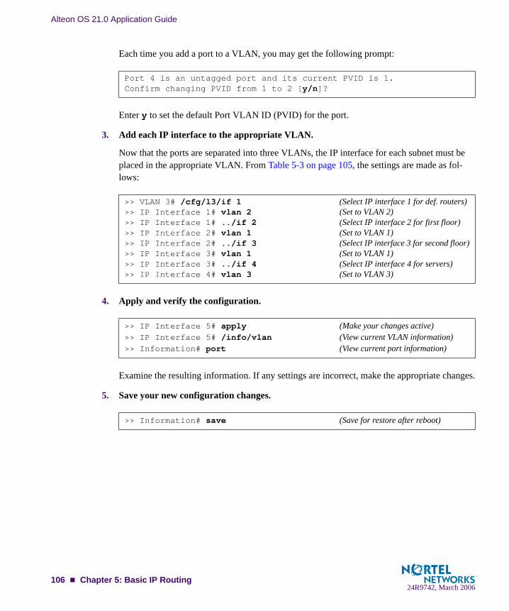
Alteon OS 21.0 Application Guide
Each time you add a port to a VLAN, you may get the following prompt:
Enter y to set the default Port VLAN ID (PVID) for the port.
3. Add each IP interface to the appropriate VLAN.
Now that the ports are separated into three VLANs, the IP interface for each subnet must be placed in the appropriate VLAN. From Table 5-3 on page 105, the settings are made as fol-lows:
4. Apply and verify the configuration.
Examine the resulting information. If any settings are incorrect, make the appropriate changes.
5. Save your new configuration changes.
Port 4 is an untagged port and its current PVID is 1.Confirm changing PVID from 1 to 2 [y/n]?
>> VLAN 3# /cfg/l3/if 1 (Select IP interface 1 for def. routers)>> IP Interface 1# vlan 2 (Set to VLAN 2)>> IP Interface 1# ../if 2 (Select IP interface 2 for first floor)>> IP Interface 2# vlan 1 (Set to VLAN 1)>> IP Interface 2# ../if 3 (Select IP interface 3 for second floor)>> IP Interface 3# vlan 1 (Set to VLAN 1)>> IP Interface 3# ../if 4 (Select IP interface 4 for servers)>> IP Interface 4# vlan 3 (Set to VLAN 3)
>> IP Interface 5# apply (Make your changes active)>> IP Interface 5# /info/vlan (View current VLAN information)>> Information# port (View current port information)
>> Information# save (Save for restore after reboot)
106 Chapter 5: Basic IP Routing24R9742, March 2006

Alteon OS 21.0 Application Guide
Defining IP Address Ranges for the Local Route CacheA local route cache lets you use switch resources more efficiently. The local network address and local network mask parameters (accessed via the /cfg/l3/frwd/local/add com-mand) define a range of addresses that will be cached on the switch. The local network address is used to define the base IP address in the range that will be cached. The local network mask is applied to produce the range. To determine if a route should be added to the memory cache, the destination address is masked (bit-wise AND) with the local network mask and checked against the local network address.
By default, the local network address and local network mask are both set to 0.0.0.0. This pro-duces a range that includes all Internet addresses for route caching: 0.0.0.0 through 255.255.255.255.
To limit the route cache to your local hosts, you could configure the parameters as shown in the following example:
NOTE – Static routes must be configured within the configured range. All other addresses that fall outside the defined range are forwarded to the default gateway.
Table 5-4 Local Routing Cache Address Ranges
Local Host Address Range Local Network Address Local Network Mask
0.0.0.0 - 127.255.255.255 0.0.0.0 128.0.0.0
128.0.0.0 - 128.255.255.255 128.0.0.0 128.0.0.0 or 255.0.0.0
205.32.0.0 - 205.32.255.255 205.32.0.0 255.255.0.0
Chapter 5: Basic IP Routing 10724R9742, March 2006

Alteon OS 21.0 Application Guide
Configuring Static Multicast RoutesStatic Multicast Routing routes multicast packets to multicast groups. Static Multicast Routing is independent of any unicast routing protocol and source-specific information contained in IPMC packets.
You can configure a list of ports/trunks on a VLAN for a multicast group address as hosts or primary or backup Mrouters. All subsequent IPMC data packets for that multicast group are routed to these ports.
Static Multicast routes overrides dynamic/IGMP learned groups. If dynamic groups exist for a statically configured multicast route entry with same IPMC destination, the groups are purged.
Use the command /cfg/l3/mroute to configure static multicast routes on the GbESM.
Dynamic Host Configuration ProtocolDynamic Host Configuration Protocol (DHCP) is a transport protocol that provides a frame-work for automatically assigning IP addresses and configuration information to other IP hosts or clients in a large TCP/IP network. Without DHCP, the IP address must be entered manually for each network device. DHCP allows a network administrator to distribute IP addresses from a central point and automatically send a new IP address when a device is connected to a differ-ent place in the network.
DHCP is an extension of another network IP management protocol, Bootstrap Protocol (BOOTP), with an additional capability of being able to dynamically allocate reusable network addresses and configuration parameters for client operation.
Built on the client/server model, DHCP allows hosts or clients on an IP network to obtain their configurations from a DHCP server, thereby reducing network administration. The most sig-nificant configuration the client receives from the server is its required IP address; (other optional parameters include the “generic” file name to be booted, the address of the default gateway, and so forth).
Nortel Networks DHCP relay agent eliminates the need to have DHCP/BOOTP servers on every subnet. It allows the administrator to reduce the number of DHCP servers deployed on the network and to centralize them. Without the DHCP relay agent, there must be at least one DHCP server deployed at each subnet that has hosts needing to perform the DHCP request.
108 Chapter 5: Basic IP Routing24R9742, March 2006

Alteon OS 21.0 Application Guide
DHCP Relay AgentDHCP is described in RFC 2131, and the DHCP relay agent supported on GbE Switch Mod-ules is described in RFC 1542. DHCP uses UDP as its transport protocol. The client sends messages to the server on port 67 and the server sends messages to the client on port 68.
DHCP defines the methods through which clients can be assigned an IP address for a finite lease period and allowing reassignment of the IP address to another client later. Additionally, DHCP provides the mechanism for a client to gather other IP configuration parameters it needs to operate in the TCP/IP network.
In the DHCP environment, the GbE Switch Module acts as a relay agent. The DHCP relay fea-ture (/cfg/l3/bootp) enables the switch to forward a client request for an IP address to two BOOTP servers with IP addresses that have been configured on the switch.
When a switch receives a UDP broadcast on port 67 from a DHCP client requesting an IP address, the switch acts as a proxy for the client, replacing the client source IP (SIP) and desti-nation IP (DIP) addresses. The request is then forwarded as a UDP Unicast MAC layer mes-sage to two BOOTP servers whose IP addresses are configured on the switch. The servers respond as a UDP Unicast message back to the switch, with the default gateway and IP address for the client. The destination IP address in the server response represents the interface address on the switch that received the client request. This interface address tells the switch on which VLAN to send the server response to the client.
Chapter 5: Basic IP Routing 10924R9742, March 2006
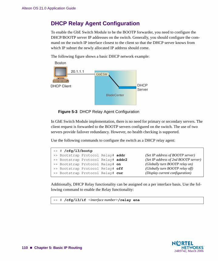
Alteon OS 21.0 Application Guide
DHCP Relay Agent ConfigurationTo enable the GbE Switch Module to be the BOOTP forwarder, you need to configure the DHCP/BOOTP server IP addresses on the switch. Generally, you should configure the com-mand on the switch IP interface closest to the client so that the DHCP server knows from which IP subnet the newly allocated IP address should come.
The following figure shows a basic DHCP network example:
Figure 5-3 DHCP Relay Agent Configuration
In GbE Switch Module implementation, there is no need for primary or secondary servers. The client request is forwarded to the BOOTP servers configured on the switch. The use of two servers provide failover redundancy. However, no health checking is supported.
Use the following commands to configure the switch as a DHCP relay agent:
Additionally, DHCP Relay functionality can be assigned on a per interface basis. Use the fol-lowing command to enable the Relay functionality:
>> # /cfg/l3/bootp>> Bootstrap Protocol Relay# addr (Set IP address of BOOTP server)>> Bootstrap Protocol Relay# addr2 (Set IP address of 2nd BOOTP server)>> Bootstrap Protocol Relay# on (Globally turn BOOTP relay on)>> Bootstrap Protocol Relay# off (Globally turn BOOTP relay off) >> Bootstrap Protocol Relay# cur (Display current configuration)
>> # /cfg/l3/if <interface number>/relay ena
BladeCenterBladeCenter
DHCPServer
GbESM
110 Chapter 5: Basic IP Routing24R9742, March 2006

CHAPTER 6Routing Information Protocol
In a routed environment, routers communicate with one another to keep track of available routes. Routers can learn about available routes dynamically using the Routing Information Protocol (RIP). The Alteon OS software implements standard RIP for exchanging TCP/IP route information with other routers.
Distance Vector ProtocolRIP is known as a distance vector protocol. The vector is the network number and next hop, and the distance is the cost associated with the network number. RIP identifies network reach-ability based on cost, and cost is defined as hop count. One hop is considered to be the distance from one switch to the next which is typically 1. This cost or hop count is known as the metric.
When a switch receives a routing update that contains a new or changed destination network entry, the switch adds 1 to the metric value indicated in the update and enters the network in the routing table. The IP address of the sender is used as the next hop.
StabilityRIP version 1 was distributed in the early years of the Internet and advertised default class address without subnet masking. RIP is stable, widely supported, and easy to configure. Use RIP in stub networks and in small autonomous systems that do not have many redundant paths.
RIP includes a number of other stability features that are common to many routing protocols. For example, RIP implements the split horizon and holddown mechanisms to prevent incorrect routing information from being propagated.
RIP prevents routing loops from continuing indefinitely by implementing a limit on the num-ber of hops allowed in a path from the source to a destination. The maximum number of hops in a path is 15. The network destination network is considered unreachable if increasing the metric value by 1 causes the metric to be 16 (that is infinity). This limits the maximum diame-ter of a RIP network to less than 16 hops.
24R9742, March 2006111

Alteon OS 21.0 Application Guide
Routing UpdatesRIP sends routing-update messages at regular intervals and when the network topology changes. RIP uses broadcast User Datagram Protocol (UDP) data packets to exchange routing information. Each router “advertises” routing information by sending a routing information update every 30 seconds. If a router does not receive an update from another router within 90 seconds, it marks the routes served by the non-updating router as being unusable. If no update is received within 240 seconds, the router removes all routing table entries for the non-updat-ing router.
When a router receives a routing update that includes changes to an entry, it updates its routing table to reflect the new route. The metric value for the path is increased by 1, and the sender is indicated as the next hop. RIP routers maintain only the best route (the route with the lowest metric value) to a destination.
For more information see The Configuration Menu, Routing Information Protocol Configura-tion (/cfg/l3/rip1) in the Alteon OS Command Reference.
112 Chapter 6: Routing Information Protocol24R9742, March 2006

CHAPTER 7IGMP Snooping
IGMP Snooping allows the switch to forward multicast traffic only to those ports that request it. IGMP Snooping prevents multicast traffic from being flooded to all ports. The switch learns which server hosts are interested in receiving multicast traffic, and forwards it only to ports connected to those servers.
The following topics are discussed in this chapter:
“Overview” on page 114
“FastLeave” on page 115
“Static Multicast Router” on page 116
“IGMP Snooping Configuration Example” on page 117
24R9742, March 2006113

Alteon OS 21.0 Application Guide
OverviewInternet Group Management Protocol (IGMP) is used by IP Multicast routers to learn about the existence of host group members on their directly attached subnet (see RFC 2236). The IP Multicast routers get this information by broadcasting IGMP Membership Queries and listen-ing for IP hosts reporting their host group memberships. This process is used to set up a client/server relationship between an IP Multicast source that provides the data streams and the cli-ents that want to receive the data.
IGMP Snooping conserves bandwidth. With IGMP Snooping, the switch learns which ports are interested in receiving multicast data, and forwards multicast data only to those ports. In this way, other ports are not burdened with unwanted multicast traffic.
IGMP Snooping operates on a VLAN by VLAN basis. Interested ports in a given VLAN receive multicast traffic, and uninterested ports in the same VLAN do not. Up to eight VLANs can participate in IGMP Snooping.
The GbESM currently supports snooping for IGMP version 1 and version 2.
The switch can sense IGMP Membership Reports from attached clients and act as a proxy to set up a dedicated path between the requesting host and a local IP Multicast router. After the pathway is established, the switch blocks the IP Multicast stream from flowing through any port that does not connect to a host member, thus conserving bandwidth.
The client-server path is set up as follows:
An IP Multicast Router (MRouter) sends Membership Queries to the switch, which for-wards them to all ports in a given VLAN.
Hosts that want to receive the multicast data stream send Membership Reports to the switch, which sends a proxy Membership Report to the MRouter.
The switch sets up a path between the MRouter and the host, and blocks all other ports from receiving the multicast.
Periodically, the MRouter sends Membership Queries to ensure that the host wants to con-tinue receiving the multicast. If a host fails to respond with a Membership Report, the MRouter stops sending the multicast to that path.
The host can send a Leave report to the switch, which sends a proxy Leave report to the MRouter. The multicast path is terminated immediately.
114 Chapter 7: IGMP Snooping24R9742, March 2006

Alteon OS 21.0 Application Guide
FastLeaveIn normal operation, when the switch with IGMP Snooping enabled receives an IGMPv2 leave message, it sends a Group-Specific Query to determine if any other devices in the same group (and on the same port) are still interested in the specified multicast group traffic. The switch removes the affiliated port from that particular group, if the following conditions apply:
If the switch does not receive an IGMP Membership Report within the query-response-interval.
If no multicast routers have been learnt on that port.
With FastLeave enabled on the VLAN, a port can be removed immediately from the port list of the group entry when the IGMP Leave message is received, unless a multicast router was learnt on the port.
Enable FastLeave only on VLANs that have only one host connected to each physical port.
IGMP FilteringWith IGMP Filtering, you can allow or deny a port to send and receive multicast traffic to cer-tain multicast groups. Unauthorized users are restricted from streaming multicast traffic across the network.
If access to a multicast group is denied, IGMP Membership Reports from the port are dropped, and the port is not allowed to receive IP multicast traffic from that group. If access to the mul-ticast group is allowed, Membership Reports from the port are forwarded for normal process-ing.
To configure IGMP Filtering, you must globally enable IGMP filtering, define an IGMP filter, assign the filter to a port, and enable IGMP Filtering on the port. To define an IGMP filter, you must configure a range of IP multicast groups, choose whether the filter will allow or deny multicast traffic for groups within the range, and enable the filter.
Configuring the RangeEach IGMP Filter allows you to set a start and end point that defines the range of IP addresses upon which the filter takes action. Each IP address in the range must be between 224.0.1.0 and 239.255.255.255. If you choose any as the start point, then the filter acts upon all addresses between 224.0.0.0 and the address entered as the end point. If you enter any as the end point, then the filter acts upon all addresses between the address entered as the start point and 239.255.255.255.
Chapter 7: IGMP Snooping 11524R9742, March 2006
Alteon OS 21.0 Application Guide
Configuring the ActionEach IGMP filter can allow or deny IP multicasts to the range of IP addresses configured. If you configure the filter to deny IP multicasts, then IGMP Membership Reports from multicast groups within the range are dropped. You can configure a secondary filter to allow IP multi-casts to a small range of addresses within a larger range that a primary filter is configured to deny. The two filters work together to allow IP multicasts to a small subset of addresses within the larger range of addresses.
Static Multicast RouterA static multicast router (MRouter) can be configured for a particular port on a particular VLAN. A static MRouter does not have to be learned through IGMP Snooping.
A total of 16 static MRouters can be configured on the GbESM. Both internal and external ports can accept a static MRouter.
When you configure a static MRouter on a VLAN, it replaces any dynamic MRouters learnt through IGMP Snooping.
116 Chapter 7: IGMP Snooping24R9742, March 2006
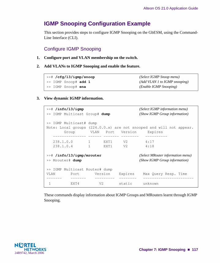
Alteon OS 21.0 Application Guide
IGMP Snooping Configuration ExampleThis section provides steps to configure IGMP Snooping on the GbESM, using the Command-Line Interface (CLI).
Configure IGMP Snooping
1. Configure port and VLAN membership on the switch.
2. Add VLANs to IGMP Snooping and enable the feature.
3. View dynamic IGMP information.
These commands display information about IGMP Groups and MRouters learnt through IGMP Snooping.
>># /cfg/l3/igmp/snoop (Select IGMP Snoop menu)>> IGMP Snoop# add 1 (Add VLAN 1 to IGMP snooping)>> IGMP Snoop# ena (Enable IGMP Snooping)
>># /info/l3/igmp (Select IGMP information menu)>> IGMP Multicast Group# dump (Show IGMP Group information)
>> IGMP Multicast# dumpNote: Local groups (224.0.0.x) are not snooped and will not appear. Group VLAN Port Version Expires --------------- ------ ------- -------- ----------
238.1.0.0 1 EXT1 V2 4:17 238.1.0.4 1 EXT1 V2 4:18 >># /info/l3/igmp/mrouter (Select MRouter information menu)>> Mrouter# dump (Show IGMP Group information)
>> IGMP Multicast Router# dumpVLAN Port Version Expires Max Query Resp. Time------- ------- --------- -------- ----------------------- 1 EXT4 V2 static unknown
Chapter 7: IGMP Snooping 11724R9742, March 2006

Alteon OS 21.0 Application Guide
Configure IGMP Filtering
1. Enable IGMP Filtering on the switch.
2. Define an IGMP filter.
3. Assign the IGMP filter to a port.
Configure a Static Multicast Router
1. Configure a port to which the static Multicast Router is connected, and enter the appro-priate VLAN.
>># /cfg/l3/igmp/igmpflt (Select IGMP Filtering menu)>> IGMP Filter# ena (Enable IGMP Filtering)Current status: disabledNew status: enabled
>># /cfg/l3/igmp/igmpflt (Select IGMP Filtering menu)>>IGMP Filter# filter 1 (Select Filter 1 Definition menu)>>IGMP Filter 1 Definition# range 224.0.1.0 (Enter first IP address of the range)Current multicast address2: anyEnter new multicast address2 or any: 226.0.0.0 (Enter second IP address)Current multicast address1: anyNew pending multicast address1: 224.0.1.0Current multicast address2: anyNew pending multicast address2: 226.0.0.0>>IGMP Filter 1 Definition# action deny (Deny multicast traffic)>>IGMP Filter 1 Definition# ena (Enable the filter)
>># /cfg/l3/igmp/igmpflt (Select IGMP Filtering menu)>>IGMP Filter# port EXT6 (Select port EXT6)>>IGMP Port EXT6# filt ena (Enable IGMP Filtering on the port)Current port EXT6 filtering: disabledNew port EXT6 filtering: enabled>>IGMP Port EXT6# add 1 (Add IGMP Filter 1 to the port)>>IGMP Port EXT6# apply (Make your changes active)
>># /cfg/l3/igmp/mrouter (Select IGMP MRouter menu)>> Static Multicast Router# add EXT4 (Add port EXT4 as Static MRouter port)Enter VLAN number: (1-4095) 1 (Enter the VLAN number)Enter the version number of mrouter [1|2]: 2 (Enter the IGMP version number)
118 Chapter 7: IGMP Snooping24R9742, March 2006

Alteon OS 21.0 Application Guide
2. Apply, verify, and save the configuration.
Configure a Static Multicast Router
1. Configure a port to which the static Multicast Router is connected, and enter the appro-priate VLAN.
2. Apply, verify, and save the configuration.
>> Static Multicast Router# apply (Apply the configuration)>> Static Multicast Router# cur (View the configuration)>> Static Multicast Router# save (Save the configuration)
>># /cfg/l3/igmp/mrouter (Select IGMP MRouter menu)>> Static Multicast Router# add EXT4 (Add port EXT4 as Static MRouter port)Enter VLAN number: (1-4095) 1 (Enter the VLAN number)Enter the version number of mrouter [1|2]: 2 (Enter the IGMP version number)
>> Static Multicast Router# apply (Apply the configuration)>> Static Multicast Router# cur (View the configuration)>> Static Multicast Router# save (Save the configuration)
Chapter 7: IGMP Snooping 11924R9742, March 2006

Alteon OS 21.0 Application Guide
120 Chapter 7: IGMP Snooping24R9742, March 2006
CHAPTER 8Border Gateway Protocol
Border Gateway Protocol (BGP) is an Internet protocol that enables routers on a network to share and advertise routing information with each other about the segments of the IP address space they can access within their network and with routers on external networks. BGP allows you to decide what is the “best” route for a packet to take from your network to a destination on another network rather than simply setting a default route from your border router(s) to your upstream provider(s). BGP is defined in RFC 1771.
GbE Switch Modules can advertise their IP interfaces and virtual server IP addresses using BGP and take BGP feeds from as many as 16 BGP router peers. This allows more resilience and flexibility in balancing traffic from the Internet.
The following sections are discussed in this section:
“Internal Routing Versus External Routing” on page 122“Forming BGP Peer Routers” on page 123“What is a Route Map?” on page 123“Aggregating Routes” on page 127“Redistributing Routes” on page 127“BGP Attributes” on page 128“Selecting Route Paths in BGP” on page 129“BGP Failover Configuration” on page 130“Default Redistribution and Route Aggregation Example” on page 133
24R9742, March 2006121

Alteon OS 21.0 Application Guide
Internal Routing Versus External RoutingTo ensure effective processing of network traffic, every router on your network needs to know how to send a packet (directly or indirectly) to any other location/destination in your network. This is referred to as internal routing and can be done with static routes or using active, inter-nal dynamic routing protocols, such as RIP, RIPv2, and OSPF.
Static routes, however have lower precedence than dynamic routing protocols. If the destina-tion route is not in the route cache, then the packets are forwarded to the default gateway which may be incorrect if a dynamic routing protocol is enabled.
It is also useful to tell routers outside your network (upstream providers or peers) about the routes you can access in your network. External networks (those outside your own) that are under the same administrative control are referred to as autonomous systems (AS). Sharing of routing information between autonomous systems is known as external routing.
External BGP (eBGP) is used to exchange routes between different autonomous systems whereas internal BGP (iBGP) is used to exchange routes within the same autonomous system. An iBGP is a type of internal routing protocol you can use to do active routing inside your net-work. It also carries AS path information, which is important when you are an ISP or doing BGP transit.
NOTE – The iBGP peers must be part of a fully meshed network, as shown in Figure 8-1.
Figure 8-1 iBGP and eBGP
BladeCenterBladeCenter
InternetInternet
122 Chapter 8: Border Gateway Protocol24R9742, March 2006

Alteon OS 21.0 Application Guide
Typically, an AS has one or more border routers—peer routers that exchange routes with other ASs—and an internal routing scheme that enables routers in that AS to reach every other router and destination within that AS. When you advertise routes to border routers on other autono-mous systems, you are effectively committing to carry data to the IP space represented in the route being advertised. For example, if you advertise 192.204.4.0/24, you are declaring that if another router sends you data destined for any address in 192.204.4.0/24, you know how to carry that data to its destination.
Forming BGP Peer RoutersTwo BGP routers become peers or neighbors once you establish a TCP connection between them. For each new route, if a peer is interested in that route (for example, if a peer would like to receive your static routes and the new route is static), an update message is sent to that peer containing the new route. For each route removed from the route table, if the route has already been sent to a peer, an update message containing the route to withdraw is sent to that peer.
For each Internet host, you must be able to send a packet to that host, and that host has to have a path back to you. This means that whoever provides Internet connectivity to that host must have a path to you. Ultimately, this means that they must “hear a route” which covers the section of the IP space you are using; otherwise, you will not have connectivity to the host in question.
What is a Route Map?A route map is used to control and modify routing information. Route maps define conditions for redistributing routes from one routing protocol to another or controlling routing informa-tion when injecting it in and out of BGP. Route maps are used by OSPF only for redistributing routes. For example, a route map is used to set a preference value for a specific route from a peer router and another preference value for all other routes learned via the same peer router. For example, the following command is used to define a route map:
A route map allows you to match attributes, such as metric, network address, and AS number. It also allows users to overwrite the local preference metric and to append the AS number in the AS route. See “BGP Failover Configuration” on page 130.
>> # /cfg/l3/rmap 1 (Select a route map)
Chapter 8: Border Gateway Protocol 12324R9742, March 2006
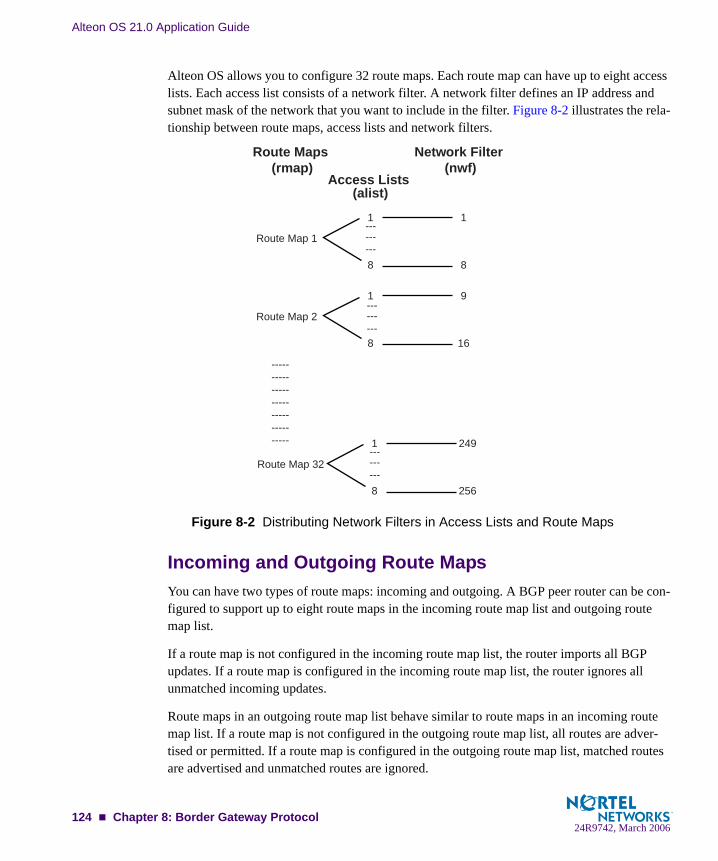
Alteon OS 21.0 Application Guide
Alteon OS allows you to configure 32 route maps. Each route map can have up to eight access lists. Each access list consists of a network filter. A network filter defines an IP address and subnet mask of the network that you want to include in the filter. Figure 8-2 illustrates the rela-tionship between route maps, access lists and network filters.
Figure 8-2 Distributing Network Filters in Access Lists and Route Maps
Incoming and Outgoing Route MapsYou can have two types of route maps: incoming and outgoing. A BGP peer router can be con-figured to support up to eight route maps in the incoming route map list and outgoing route map list.
If a route map is not configured in the incoming route map list, the router imports all BGP updates. If a route map is configured in the incoming route map list, the router ignores all unmatched incoming updates.
Route maps in an outgoing route map list behave similar to route maps in an incoming route map list. If a route map is not configured in the outgoing route map list, all routes are adver-tised or permitted. If a route map is configured in the outgoing route map list, matched routes are advertised and unmatched routes are ignored.
Access Lists (alist)
Network Filter (nwf)
Route Maps (rmap)
1
Route Map 1
8
1
8
1
Route Map 2
8
9
16
1
Route Map 32
8
249
256
-----------------------------------
------
---
------
---
------
---
124 Chapter 8: Border Gateway Protocol24R9742, March 2006

Alteon OS 21.0 Application Guide
Precedence You can set a priority to a route map by specifying a precedence value with the following com-mand:
The smaller the value the higher the precedence. If two route maps have the same precedence value, the smaller number has higher precedence.
Configuration OverviewTo configure route maps, you need to do the following:
1. Define network filter.
Enter a filter number from 1 to 256. Specify the IP address and subnet mask of the network that you want to match. Enable the network filter. You can distribute up to 256 network filters among 32 route maps each containing 8 access lists.
2. (Optional) Define the criteria for the access list and enable it.
Specify the access list and associate the network filter number configured in Step 1.
Steps 2 and 3 are optional, depending on the criteria that you want to match. In Step 2, the net-work filter number is used to match the subnets defined in the network filter. In Step 3, the autonomous system number is used to match the subnets. Or, you can use both (Step 2 and Step 3) criteria: access list (network filter) and access path (AS filter) to configure the route maps.
>> /cfg/l3/rmap/pre (Specify a precedence)
>> # /cfg/l3/nwf 1 (Specify a network filter number)>> IP Network Filter 1# addr <IP address> (Specify network address)>> IP Network Filter 1# mask <IP mask> (Specify network mask)>> IP Network Filter 1# ena (Enable network filter)
>> # /cfg/l3/rmap 1 (Specify a route map number)>> IP Route Map 1# alist 1 (Specify the access list number)>> IP Access List 1# nwf 1 (Specify the network filter number)>> IP Access List 1# metric (Define a metric)>> IP Access List 1# action deny (Specify action for the access list)>> IP Access List 1# ena (Enable the access list)
Chapter 8: Border Gateway Protocol 12524R9742, March 2006

Alteon OS 21.0 Application Guide
3. (Optional) Configure the attributes in the AS filter menu.
4. Set up the BGP attributes.
If you want to overwrite the attributes that the peer router is sending, then define the following BGP attributes:
Specify the AS numbers that you want to prepend to a matched route and the local prefer-ence for the matched route.
Specify the metric [Multi Exit Discriminator (MED)] for the matched route.
5. Enable the route map.
6. Assign the route map to a peer router.
Select the peer router and then add the route map to the incoming route map list,
or to the outgoing route map list.
>> # cfg/l3/rmap 1/aspath 1 (Specify the attributes in the filter)>> AS Filter 1# as 1 (Specify the AS number)>> AS Filter 1# action deny (Specify the action for the filter)>> AS Filter 1# ena (Enable the AS filter)
>> # cfg/l3/rmap 1 (Specify a route map number)>> IP Route Map 1# ap (Specify the AS numbers to prepend)>> IP Route Map 1# lp (Specify the local preference)>> IP Route Map 1# met (Specify the metric)
>> # cfg/l3/rmap 1/en (Enable the route map)
>> # cfg/l3/bgp/peer 1/addi (Add to the incoming route map)
>> # cfg/l3/bgp/peer 1/addo (Add to the outgoing route map)
126 Chapter 8: Border Gateway Protocol24R9742, March 2006

Alteon OS 21.0 Application Guide
Aggregating RoutesAggregation is the process of combining several different routes in such a way that a single route can be advertised, which minimizes the size of the routing table. You can configure aggregate routes in BGP either by redistributing an aggregate route into BGP or by creating an aggregate entry in the BGP routing table.
When a subnet is redistributed from an Interior Gateway Protocol (IGP) into BGP, only the network route is injected into the BGP table. By default, this automatic summarization is dis-abled. To define the route to aggregate, use the following commands:
An example of creating a BGP aggregate route is shown in “Default Redistribution and Route Aggregation Example” on page 133.
Redistributing RoutesIn addition to running multiple routing protocols simultaneously, Alteon OS software can redistribute information from one routing protocol to another. For example, you can instruct the switch to use BGP to readvertise static routes. This applies to all of the IP-based routing protocols.
You can also conditionally control the redistribution of routes between routing domains by defining a method known as route maps between the two domains. For more information on route maps, see “What is a Route Map?” on page 123. Redistributing routes is another way of providing policy control over whether to export OSPF routes, fixed routes, static routes, and virtual IP address routes. Default routes can be configured using the following methods:
Import
Originate
The router sends a default route to peers even though it does not have any default routes in its routing table.
>> # cfg/l3/bgp (Specify BGP)>> Border Gateway Protocol# aggr 1 (Specify aggregate list number)>> BGP aggr 1 # addr (Enter aggregation network address)>> BGP aggr 1 # mask (Enter aggregation network mask)>> BGP aggr 1 # ena (Enable aggregation)
Chapter 8: Border Gateway Protocol 12724R9742, March 2006
Alteon OS 21.0 Application Guide
Redistribute
Default routes are either configured through the default gateway or learned via other pro-tocols and redistributed to peer routers. If the default routes are from the default gateway, enable the static routes because default routes from the default gateway are static routes. Similarly, if the routes are learned from another routing protocol, make sure you enable that protocol for redistribution.
None
BGP AttributesThe following two BGP attributes are discussed in this section: Local preference and metric (Multi-Exit Discriminator).
Local Preference AttributeWhen there are multiple paths to the same destination, the local preference attribute indicates the preferred path. The path with the higher preference is preferred (the default value of the local preference attribute is 100). Unlike the weight attribute, which is only relevant to the local router, the local preference attribute is part of the routing update and is exchanged among routers in the same AS.
The local preference attribute can be set in one of two ways:
/cfg/l3/bgp/pref
This command uses the BGP default local preference method, affecting the outbound direction only.
/cfg/l3/rmap/lp
This command uses the route map local preference method, which affects both inbound and outbound directions.
Metric (Multi-Exit Discriminator) AttributeThis attribute is a hint to external neighbors about the preferred path into an AS when there are multiple entry points. A lower metric value is preferred over a higher metric value. The default value of the metric attribute is 0.
Unlike local preference, the metric attribute is exchanged between ASs; however, a metric attribute that comes into an AS does not leave the AS.
128 Chapter 8: Border Gateway Protocol24R9742, March 2006

Alteon OS 21.0 Application Guide
When an update enters the AS with a certain metric value, that value is used for decision mak-ing within the AS. When BGP sends that update to another AS, the metric is reset to 0.
Unless otherwise specified, the router compares metric attributes for paths from external neighbors that are in the same AS.
Selecting Route Paths in BGPBGP selects only one path as the best path. It does not rely on metrics attributes to determine the best path. When the same network is learned via more than one BGP peer, BGP uses its policy for selecting the best route to that network. The BGP implementation on the GbE Switch Module uses the following criteria to select a path when the same route is received from multiple peers.
1. Local fixed and static routes are preferred over learned routes.
2. With iBGP peers, routes with higher local preference values are selected.
3. In the case of multiple routes of equal preference, the route with lower AS path weight is selected.
AS path weight = 128 x AS path length (number of autonomous systems transversed).
4. In the case of equal weight and routes learned from peers that reside in the same AS, the lower metric is selected.
NOTE – A route with a metric is preferred over a route without a metric.
5. The lower cost to the next hop of routes is selected.
6. In the case of equal cost, the eBGP route is preferred over iBGP.
7. If all routes are from eBGP, the route with the lower router ID is selected.
When the path is selected, BGP puts the selected path in its routing table and propagates the path to its neighbors.
Chapter 8: Border Gateway Protocol 12924R9742, March 2006

Alteon OS 21.0 Application Guide
BGP Failover ConfigurationUse the following example to create redundant default gateways for a GbE Switch Module at a Web Host/ISP site, eliminating the possibility, should one gateway go down, that requests will be forwarded to an upstream router unknown to the switch.
As shown in Figure 8-3, the switch is connected to ISP 1 and ISP 2. The customer negotiates with both ISPs to allow the switch to use their peer routers as default gateways. The ISP peer routers will then need to announce themselves as default gateways to the GbE Switch Module.
Figure 8-3 BGP Failover Configuration Example
On the GbE Switch Module, one peer router (the secondary one) is configured with a longer AS path than the other, so that the peer with the shorter AS path will be seen by the switch as the primary default gateway. ISP 2, the secondary peer, is configured with a metric of “3,” thereby appearing to the switch to be three router hops away.
BladeCenterBladeCenter
GbE SwitchModule
VIP: 200.200.200.200IP: 200.200.200.1IP: 210.210.210.1
Real server 1IP: 200.200.200.10
Real server 2IP: 200.200.200.11
VIP: 200.200.200.200IP: 200.200.200.1IP: 210.210.210.1
Real server 2IP: 200.200.200.11
Real server 1IP: 200.200.200.10
GbE SwitchModule
130 Chapter 8: Border Gateway Protocol24R9742, March 2006

Alteon OS 21.0 Application Guide
1. Configure the switch as you normally would for Server Load Balancing (SLB).
Assign an IP address to each of the real servers in the server pool.Define each real server.Define a real server group.Define a virtual server.Define the port configuration.
For more information about SLB configuration, refer to Chapter 10, “Server Load Balancing.”
2. Define the VLANs.
For simplicity, both default gateways are configured in the same VLAN in this example. The gateways could be in the same VLAN or different VLANs.
3. Define the IP interfaces.
The switch will need an IP interface for each default gateway to which it will be connected. Each interface will need to be placed in the appropriate VLAN. These interfaces will be used as the primary and secondary default gateways for the switch.
4. Enable IP forwarding.
IP forwarding is enabled by default and is used for VLAN-to-VLAN (non-BGP) routing. Make sure IP forwarding is enabled if the default gateways are on different subnets or if the switch is connected to different subnets and those subnets need to communicate through the switch (which they almost always do).
>> # /cfg/l2/vlan 1 (Select VLAN 1)>> vlan 1# add <port number> (Add a port to the VLAN membership)
>> IP# metrc strict (Set metric for default gateway)>> IP# if 1 (Select default gateway interface 1)>> IP Interface 1# ena (Enable switch interface 1)>> IP Interface 1# addr 200.200.200.1 (Configure IP address of interface 1)>> IP Interface 1# mask 255.255.255.0 (Configure IP subnet address mask)>> IP Interface 1# ../ip/if 2 (Select default gateway interface 2)>> IP Interface 2# ena (Enable switch interface 2)>> IP Interface 2# addr 210.210.210.1 (Configure IP address of interface 2)>> IP Interface 2# mask 255.255.255.0 (Configure IP subnet address mask)
>> /cfg/l3/frwd on (Enable IP forwarding)
Chapter 8: Border Gateway Protocol 13124R9742, March 2006

Alteon OS 21.0 Application Guide
NOTE – To help eliminate the possibility for a Denial of Service (DoS) attack, the forwarding of directed broadcasts is disabled by default.
5. Configure BGP peer router 1 and 2.
Peer 1 is the primary gateway router. Peer 2 is configured with a metric of “3.” The metric option is key to ensuring gateway traffic is directed to Peer 1, as it will make Peer 2 appear to be three router hops away from the switch. Thus, the switch should never use it unless Peer 1 goes down.
The metric command in the peer menu tells the GbE Switch Module to create an AS path of “3” when advertising via BGP.
6. On the switch, apply and save your configuration changes.
>> # /cfg/l3/bgp/peer 1 (Select BGP peer router 1)>> BGP Peer 1# ena (Enable this peer configuration)>> BGP Peer 1# addr 200.200.200.2 (Set IP address for peer router 1)>> BGP Peer 1# if 200.200.200.1 (Set IP interface for peer router 1)>> BGP Peer 1# ras 100 (Set remote AS number)>> BGP Peer 1# ../peer 2 (Select BGP peer router 2)>> BGP Peer 2# ena (Enable this peer configuration)>> BGP Peer 2# addr 210.210.210.2 (Set IP address for peer router 2)>> BGP Peer 2# if 210.210.210.1 (Set IP interface for peer router 2)>> BGP Peer 2# ras 200 (Set remote AS number)>> BGP Peer 2# metric 3 (Set AS path length to 3 router hops)
>> BGP Peer 2# apply (Make your changes active)>> save (Save for restore after reboot)
132 Chapter 8: Border Gateway Protocol24R9742, March 2006

Alteon OS 21.0 Application Guide
Default Redistribution and Route Aggregation ExampleThis example shows you how to configure the switch to redistribute information from one routing protocol to another and create an aggregate route entry in the BGP routing table to min-imize the size of the routing table.
As illustrated in Figure 8-4, you have two peer routers: an internal and an external peer router. Configure the GbE Switch Module to redistribute the default routes from AS 200 to AS 135. At the same time, configure for route aggregation to allow you to condense the number of routes traversing from AS 135 to AS 200.
Figure 8-4 Route Aggregation and Default Route Redistribution
1. Configure the IP interface.
2. Configure the AS number (AS 135) and router ID number (10.1.1.135).
>> # /cfg/l3/bgp (Select BGP menu)>> Border Gateway Protocol# as 135 (Specify an AS number)>> Border Gateway Protocol# .. rtrid 0.0.0.1(Specify a router ID number)
BladeCenterBladeCenter
GbE Switch Module10.1.1.135
GbE Switch Module10.1.1.135
Chapter 8: Border Gateway Protocol 13324R9742, March 2006

Alteon OS 21.0 Application Guide
3. Configure internal peer router 1 and external peer router 2.
4. Configure redistribution for Peer 1.
5. Configure aggregation policy control.
Configure the routes that you want aggregated.
>> # /cfg/l3/bgp/peer 1 (Select internal peer router 1)>> BGP Peer 1# ena (Enable this peer configuration)>> BGP Peer 1# addr 10.1.1.4 (Set IP address for peer router 1)>> BGP Peer 1# ras 135 (Set remote AS number)>> BGP Peer 1# ../peer 2 (Select external peer router 2)>> BGP Peer 2# ena (Enable this peer configuration)>> BGP Peer 2# addr 20.20.20.2 (Set IP address for peer router 2)>> BGP Peer 2# ras 200 (Set remote AS number)
>> # /cfg/l3/bgp/peer 1/redist (Select redistribute)>> BGP Peer 1# default redistribute (Set default to redistribute)>> BGP Peer 1# fixed ena (Enable fixed routes)
>> # /cfg/l3/bgp/aggr 1 (Set aggregation number)>> BGP aggr 1# addr 135.0.0.0 (Add IP address to aggregate 1)>> BGP Peer 1# mask 255.0.0.0 (Add IP mask to aggregate 1)
134 Chapter 8: Border Gateway Protocol24R9742, March 2006

CHAPTER 9OSPF
Alteon OS supports the Open Shortest Path First (OSPF) routing protocol. The Alteon OS implementation conforms to the OSPF version 2 specifications detailed in Internet RFC 1583. The following sections discuss OSPF support for the GbE Switch Module:
“OSPF Overview” on page 136. This section provides information on OSPF concepts, such as types of OSPF areas, types of routing devices, neighbors, adjacencies, link state database, authentication, and internal versus external routing.
“OSPF Implementation in Alteon OS” on page 141. This section describes how OSPF is implemented in Alteon OS, such as configuration parameters, electing the designated router, summarizing routes, defining route maps and so forth.
“OSPF Configuration Examples” on page 151. This section provides step-by-step instruc-tions on configuring four different configuration examples:
Creating a simple OSPF domain
Creating virtual links
Summarizing routes
Creating host routes
24R9742, March 2006135

Alteon OS 21.0 Application Guide
OSPF OverviewOSPF is designed for routing traffic within a single IP domain called an Autonomous System (AS). The AS can be divided into smaller logical units known as areas.
All routing devices maintain link information in their own Link State Database (LSDB). The LSDB for all routing devices within an area is identical but is not exchanged between different areas. Only routing updates are exchanged between areas, thereby significantly reducing the overhead for maintaining routing information on a large, dynamic network.
The following sections describe key OSPF concepts.
Equal Cost Multipath Routing SupportEqual-cost multipath (ECMP) is a routing technique for routing packets along multiple paths of equal cost. The routing table contains multiple next-hops for any given destination. The router load balances packets along the multiple next-hops. The GbESM supports ECMP, and there are no CLI additions or changes.
Types of OSPF AreasAn AS can be broken into logical units known as areas. In any AS with multiple areas, one area must be designated as area 0, known as the backbone. The backbone acts as the central OSPF area. All other areas in the AS must be connected to the backbone. Areas inject sum-mary routing information into the backbone, which then distributes it to other areas as needed.
As shown in Figure 9-1, OSPF defines the following types of areas:
Stub Area—an area that is connected to only one other area. External route information is not distributed into stub areas.
Not-So-Stubby-Area (NSSA)—similar to a stub area with additional capabilities. Routes originating from within the NSSA can be propagated to adjacent transit and backbone areas. External routes from outside the AS can be advertised within the NSSA but are not distributed into other areas.
136 Chapter 9: OSPF24R9742, March 2006

Alteon OS 21.0 Application Guide
Transit Area—an area that allows area summary information to be exchanged between routing devices. The backbone (area 0), any area that contains a virtual link to connect two areas, and any area that is not a stub area or an NSSA are considered transit areas.
Figure 9-1 OSPF Area Types
BackboneArea 0
Stub AreaNot-So-Stubby Area
(NSSA)
Transit AreaNo External Routes
from Backbone
Stub Area, NSSA,or Transit Area
Connected to Backbonevia Virtual Link
(Also a Transit Area)
External LSA Routes
Internal LSA Routes
ABR ABRABR
ASBR
Non-OSPF AreaRIP/BGP AS
VirtualLink
ABR
ABR = Area Border RouterASBR = Autonomous System
Boundary Router
Chapter 9: OSPF 13724R9742, March 2006
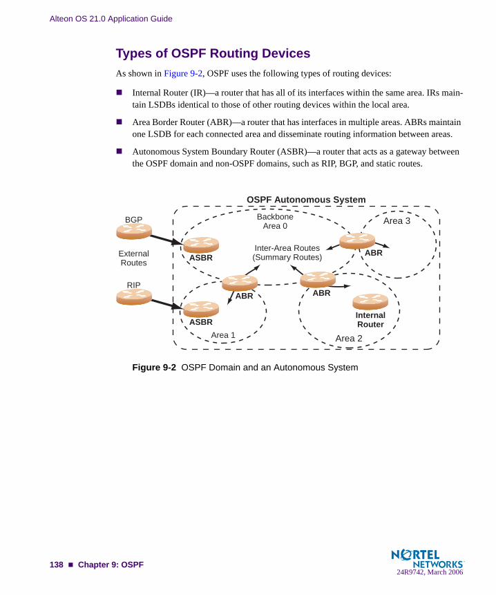
Alteon OS 21.0 Application Guide
Types of OSPF Routing DevicesAs shown in Figure 9-2, OSPF uses the following types of routing devices:
Internal Router (IR)—a router that has all of its interfaces within the same area. IRs main-tain LSDBs identical to those of other routing devices within the local area.
Area Border Router (ABR)—a router that has interfaces in multiple areas. ABRs maintain one LSDB for each connected area and disseminate routing information between areas.
Autonomous System Boundary Router (ASBR)—a router that acts as a gateway between the OSPF domain and non-OSPF domains, such as RIP, BGP, and static routes.
Figure 9-2 OSPF Domain and an Autonomous System
BackboneArea 0
Area 3
Area 2Area 1
Inter-Area Routes(Summary Routes) ABR
ABRABR
ASBR
InternalRouterASBR
ExternalRoutes
BGP
RIP
OSPF Autonomous System
138 Chapter 9: OSPF24R9742, March 2006

Alteon OS 21.0 Application Guide
Neighbors and AdjacenciesIn areas with two or more routing devices, neighbors and adjacencies are formed.
Neighbors are routing devices that maintain information about each others’ health. To establish neighbor relationships, routing devices periodically send hello packets on each of their inter-faces. All routing devices that share a common network segment, appear in the same area, and have the same health parameters (hello and dead intervals) and authentication parameters respond to each other’s hello packets and become neighbors. Neighbors continue to send peri-odic hello packets to advertise their health to neighbors. In turn, they listen to hello packets to determine the health of their neighbors and to establish contact with new neighbors.
The hello process is used for electing one of the neighbors as the area’s Designated Router (DR) and one as the area’s Backup Designated Router (BDR). The DR is adjacent to all other neighbors and acts as the central contact for database exchanges. Each neighbor sends its data-base information to the DR, which relays the information to the other neighbors.
The BDR is adjacent to all other neighbors (including the DR). Each neighbor sends its data-base information to the BDR just as with the DR, but the BDR merely stores this data and does not distribute it. If the DR fails, the BDR will take over the task of distributing database infor-mation to the other neighbors.
The Link-State DatabaseOSPF is a link-state routing protocol. A link represents an interface (or routable path) from the routing device. By establishing an adjacency with the DR, each routing device in an OSPF area maintains an identical Link-State Database (LSDB) describing the network topology for its area.
Each routing device transmits a Link-State Advertisement (LSA) on each of its interfaces. LSAs are entered into the LSDB of each routing device. OSPF uses flooding to distribute LSAs between routing devices.
When LSAs result in changes to the routing device’s LSDB, the routing device forwards the changes to the adjacent neighbors (the DR and BDR) for distribution to the other neighbors.
OSPF routing updates occur only when changes occur, instead of periodically. For each new route, if an adjacency is interested in that route (for example, if configured to receive static routes and the new route is indeed static), an update message containing the new route is sent to the adjacency. For each route removed from the route table, if the route has already been sent to an adjacency, an update message containing the route to withdraw is sent.
Chapter 9: OSPF 13924R9742, March 2006

Alteon OS 21.0 Application Guide
The Shortest Path First TreeThe routing devices use a link-state algorithm (Dijkstra’s algorithm) to calculate the shortest path to all known destinations, based on the cumulative cost required to reach the destination.
The cost of an individual interface in OSPF is an indication of the overhead required to send packets across it. The cost is inversely proportional to the bandwidth of the interface. A lower cost indicates a higher bandwidth.
Internal Versus External RoutingTo ensure effective processing of network traffic, every routing device on your network needs to know how to send a packet (directly or indirectly) to any other location/destination in your network. This is referred to as internal routing and can be done with static routes or using active internal routing protocols, such as OSPF, RIP, or RIPv2.
It is also useful to tell routers outside your network (upstream providers or peers) about the routes you have access to in your network. Sharing of routing information between autono-mous systems is known as external routing.
Typically, an AS will have one or more border routers (peer routers that exchange routes with other OSPF networks) as well as an internal routing system enabling every router in that AS to reach every other router and destination within that AS.
When a routing device advertises routes to boundary routers on other autonomous systems, it is effectively committing to carry data to the IP space represented in the route being advertised. For example, if the routing device advertises 192.204.4.0/24, it is declaring that if another router sends data destined for any address in the 192.204.4.0/24 range, it will carry that data to its destination.
140 Chapter 9: OSPF24R9742, March 2006

Alteon OS 21.0 Application Guide
OSPF Implementation in Alteon OSAlteon OS supports a single instance of OSPF and up to 4 K routes on the network. The follow-ing sections describe OSPF implementation in Alteon OS:
“Configurable Parameters” on page 141“Defining Areas” on page 142“Interface Cost” on page 144“Electing the Designated Router and Backup” on page 144“Summarizing Routes” on page 144“Default Routes” on page 145“Virtual Links” on page 146“Router ID” on page 147“Authentication” on page 147“Host Routes for Load Balancing” on page 150
Configurable ParametersIn Alteon OS, OSPF parameters can be configured through the Command Line Interface (CLI), Browser-Based Interface (BBI) for GbE Switch Modules, or through SNMP. For more infor-mation, see Chapter 1, “Accessing the Switch.”
The CLI supports the following parameters: interface output cost, interface priority, dead and hello intervals, retransmission interval, and interface transmit delay.
In addition to the above parameters, you can also specify the following:
Shortest Path First (SPF) interval—Time interval between successive calculations of the shortest path tree using the Dijkstra’s algorithm.
Stub area metric—A stub area can be configured to send a numeric metric value such that all routes received via that stub area carry the configured metric to potentially influence routing decisions.
Default routes—Default routes with weight metrics can be manually injected into transit areas. This helps establish a preferred route when multiple routing devices exist between two areas. It also helps route traffic to external networks.
Chapter 9: OSPF 14124R9742, March 2006

Alteon OS 21.0 Application Guide
Defining AreasIf you are configuring multiple areas in your OSPF domain, one of the areas must be desig-nated as area 0, known as the backbone. The backbone is the central OSPF area and is usually physically connected to all other areas. The areas inject routing information into the backbone which, in turn, disseminates the information into other areas.
Since the backbone connects the areas in your network, it must be a contiguous area. If the backbone is partitioned (possibly as a result of joining separate OSPF networks), parts of the AS will be unreachable, and you will need to configure virtual links to reconnect the parti-tioned areas (see “Virtual Links” on page 146).
Up to three OSPF areas can be connected to the GbE Switch Module with Alteon OS software. To configure an area, the OSPF number must be defined and then attached to a network inter-face on the switch. The full process is explained in the following sections.
An OSPF area is defined by assigning two pieces of information—an area index and an area ID. The command to define an OSPF area is as follows:
NOTE – The aindex option above is an arbitrary index used only on the switch and does not represent the actual OSPF area number. The actual OSPF area number is defined in the areaid portion of the command as explained in the following sections.
Assigning the Area IndexThe aindex <area index> option is actually just an arbitrary index (0-2) used only by the GbE Switch Module. This index does not necessarily represent the OSPF area number, though for configuration simplicity, it should where possible.
For example, both of the following sets of commands define OSPF area 0 (the backbone) and area 1 because that information is held in the area ID portion of the command. However, the first set of commands is easier to maintain because the arbitrary area indexes agree with the area IDs:
Area index and area ID agree
/cfg/l3/ospf/aindex 0/areaid 0.0.0.0 (Use index 0 to set area 0 in ID octet format)/cfg/l3/ospf/aindex 1/areaid 0.0.0.1 (Use index 1 to set area 1 in ID octet format)
Area index set to an arbitrary value
/cfg/l3/ospf/aindex 1/areaid 0.0.0.0 (Use index 1 to set area 0 in ID octet format)/cfg/l3/ospf/aindex 2/areaid 0.0.0.1 (Use index 2 to set area 1 in ID octet format)
>> # /cfg/l3/ospf/aindex <area index>/areaid <n.n.n.n>
142 Chapter 9: OSPF24R9742, March 2006

Alteon OS 21.0 Application Guide
Using the Area ID to Assign the OSPF Area NumberThe OSPF area number is defined in the areaid <IP address> option. The octet format is used in order to be compatible with two different systems of notation used by other OSPF net-work vendors. There are two valid ways to designate an area ID:
Placing the area number in the last octet (0.0.0.n)Most common OSPF vendors express the area ID number as a single number. For exam-ple, the Cisco IOS-based router command “network 1.1.1.0 0.0.0.255 area 1” defines the area number simply as “area 1.” On the GbE Switch Module, using the last octet in the area ID, “area 1” is equivalent to “areaid 0.0.0.1”.
Multi-octet (IP address)Some OSPF vendors express the area ID number in multi-octet format. For example, “area 2.2.2.2” represents OSPF area 2 and can be specified directly on the GbE Switch Module as “areaid 2.2.2.2”.
NOTE – Although both types of area ID formats are supported, be sure that the area IDs are in the same format throughout an area.
Attaching an Area to a NetworkOnce an OSPF area has been defined, it must be associated with a network. To attach the area to a network, you must assign the OSPF area index to an IP interface that participates in the area. The format for the command is as follows:
For example, the following commands could be used to configure IP interface 14 for a pres-ence on the 10.10.10.1/24 network, to define OSPF area 1, and to attach the area to the net-work:
>> # /cfg/l3/ospf/if <interface number>/aindex <area index>
>> # /cfg/l3/if 14 (Select menu for IP interface 14)>> IP Interface 14# addr 10.10.10.1 (Define IP address on backbone network)>> IP Interface 14# mask 255.255.255.0 (Define IP mask on backbone)>> IP Interface 14# ena (Enable IP interface 14)>> IP Interface 14# ../ospf/aindex 1 (Select menu for area index 1)>> OSPF Area (index) 1 # areaid 0.0.0.1 (Define area ID as OSPF area 1)>> OSPF Area (index) 1 # ena (Enable area index 1)>> OSPF Area (index) 1 # ../if 14 (Select OSPF menu for interface 14)>> OSPF Interface 14# aindex 1 (Attach area to network on interface
14)>> OSPF Interface 14# enable (Enable interface 14 for area index 1)
Chapter 9: OSPF 14324R9742, March 2006

Alteon OS 21.0 Application Guide
Interface CostThe OSPF link-state algorithm (Dijkstra’s algorithm) places each routing device at the root of a tree and determines the cumulative cost required to reach each destination. Usually, the cost is inversely proportional to the bandwidth of the interface. Low cost indicates high bandwidth. You can manually enter the cost for the output route with the following command:
Electing the Designated Router and BackupIn any area with more than two routing devices, a Designated Router (DR) is elected as the central contact for database exchanges among neighbors, and a Backup Designated Router (BDR) is elected in case the DR fails.
DR and BDR elections are made through the hello process. The election can be influenced by assigning a priority value to the OSPF interfaces on the GbE Switch Module. The command is as follows:
A priority value of 127 is the highest, and 1 is the lowest. A priority value of 0 specifies that the interface cannot be used as a DR or BDR. In case of a tie, the routing device with the low-est router ID wins.
Summarizing RoutesRoute summarization condenses routing information. Without summarization, each routing device in an OSPF network would retain a route to every subnet in the network. With summa-rization, routing devices can reduce some sets of routes to a single advertisement, reducing both the load on the routing device and the perceived complexity of the network. The impor-tance of route summarization increases with network size.
Summary routes can be defined for up to 16 IP address ranges using the following command:
where <range number> is a number 1 to 16, <IP address> is the base IP address for the range, and <mask> is the IP address mask for the range. For a detailed configuration example, see “Example 3: Summarizing Routes” on page 158.
>> # /cfg/l3/ospf/if <OSPF interface number>/cost <cost value (1-65535)>
>> # /cfg/l3/ospf/if <OSPF interface number>/prio <priority value (0-127)>
>> # /cfg/l3/ospf/range <range number>/addr <IP address>/mask <mask>
144 Chapter 9: OSPF24R9742, March 2006
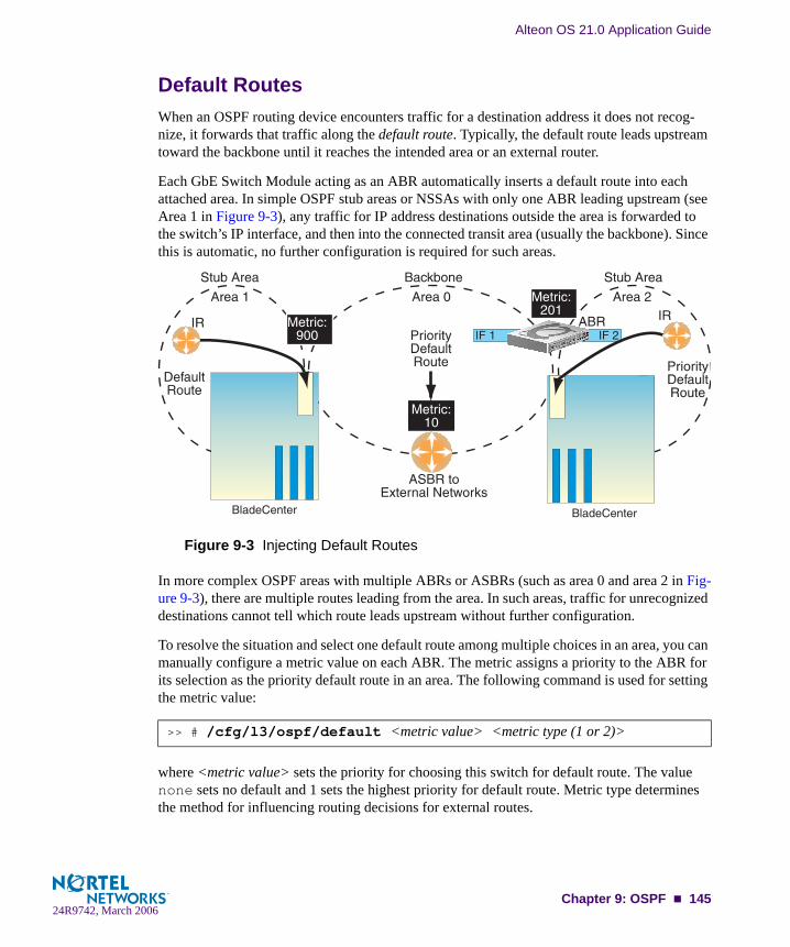
Alteon OS 21.0 Application Guide
Default RoutesWhen an OSPF routing device encounters traffic for a destination address it does not recog-nize, it forwards that traffic along the default route. Typically, the default route leads upstream toward the backbone until it reaches the intended area or an external router.
Each GbE Switch Module acting as an ABR automatically inserts a default route into each attached area. In simple OSPF stub areas or NSSAs with only one ABR leading upstream (see Area 1 in Figure 9-3), any traffic for IP address destinations outside the area is forwarded to the switch’s IP interface, and then into the connected transit area (usually the backbone). Since this is automatic, no further configuration is required for such areas.
Figure 9-3 Injecting Default Routes
In more complex OSPF areas with multiple ABRs or ASBRs (such as area 0 and area 2 in Fig-ure 9-3), there are multiple routes leading from the area. In such areas, traffic for unrecognized destinations cannot tell which route leads upstream without further configuration.
To resolve the situation and select one default route among multiple choices in an area, you can manually configure a metric value on each ABR. The metric assigns a priority to the ABR for its selection as the priority default route in an area. The following command is used for setting the metric value:
where <metric value> sets the priority for choosing this switch for default route. The value none sets no default and 1 sets the highest priority for default route. Metric type determines the method for influencing routing decisions for external routes.
>> # /cfg/l3/ospf/default <metric value> <metric type (1 or 2)>
BladeCenter BladeCenter
Chapter 9: OSPF 14524R9742, March 2006
Alteon OS 21.0 Application Guide
To clear a default route metric from the switch, use the following command:
Virtual LinksUsually, all areas in an OSPF AS are physically connected to the backbone. In some cases where this is not possible, you can use a virtual link. Virtual links are created to connect one area to the backbone through another non-backbone area (see Figure 9-1 on page 137).
The area which contains a virtual link must be a transit area and have full routing information. Virtual links cannot be configured inside a stub area or NSSA. The area type must be defined as transit using the following command:
The virtual link must be configured on the routing devices at each endpoint of the virtual link, though they may traverse multiple routing devices. To configure a GbE Switch Module as one endpoint of a virtual link, use the following command:
where <link number> is a value between 1 and 3, <area index> is the OSPF area index of the transit area, and <router ID> is the IP address of the virtual neighbor (nbr), the routing device at the target endpoint. Another router ID is needed when configuring a virtual link in the other direction. To provide the GbE Switch Module with a router ID, see the following section Router ID.
For a detailed configuration example on Virtual Links, see “Example 2: Virtual Links” on page 154.
>> # /cfg/l3/ospf/default none
>> # /cfg/l3/ospf/aindex <area index>/type transit
>> # /cfg/l3/ospf/virt <link number>/aindex <area index>/nbr <router ID>
146 Chapter 9: OSPF24R9742, March 2006
Alteon OS 21.0 Application Guide
Router IDRouting devices in OSPF areas are identified by a router ID. The router ID is expressed in IP address format. The IP address of the router ID is not required to be included in any IP inter-face range or in any OSPF area.
The router ID can be configured in one of the following two ways:
Dynamically—OSPF protocol configures the lowest IP interface IP address as the router ID. This is the default. Statically—Use the following command to manually configure the router ID:
To modify the router ID from static to dynamic, set the router ID to 0.0.0.0, save the con-figuration, and reboot the GbE Switch Module. To view the router ID, enter:
AuthenticationOSPF protocol exchanges can be authenticated so that only trusted routing devices can partici-pate. This ensures less processing on routing devices that are not listening to OSPF packets.
OSPF allows packet authentication and uses IP multicast when sending and receiving packets. Routers participate in routing domains based on predefined passwords. Alteon OS supports simple password (type 1 plain text passwords) and MD5 cryptographic authentication. This type of authentication allows a password to be configured per area.
>> # /cfg/l3/rtrid <IP address>
>> # /info/l3/ospf/gen
Chapter 9: OSPF 14724R9742, March 2006
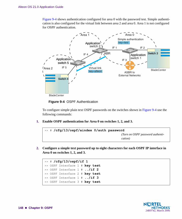
Alteon OS 21.0 Application Guide
Figure 9-4 shows authentication configured for area 0 with the password test. Simple authenti-cation is also configured for the virtual link between area 2 and area 0. Area 1 is not configured for OSPF authentication.
Figure 9-4 OSPF Authentication
To configure simple plain text OSPF passwords on the switches shown in Figure 9-4 use the following commands:
1. Enable OSPF authentication for Area 0 on switches 1, 2, and 3.
2. Configure a simple text password up to eight characters for each OSPF IP interface in Area 0 on switches 1, 2, and 3.
>> # /cfg/l3/ospf/aindex 0/auth password(Turn on OSPF password authenti-cation)
>> # /cfg/l3/ospf/if 1>> OSPF Interface 1 # key test>> OSPF Interface 1 # ../if 2>> OSPF Interface 2 # key test>> OSPF Interface 1 # ../if 3>> OSPF Interface 3 # key test
BladeCenter
BladeCenter
ApplicationApplication
ApplicationApplication
Switch 3Switch 3
Application switch 5Application switch 5
Switch 4Switch 4
148 Chapter 9: OSPF24R9742, March 2006

Alteon OS 21.0 Application Guide
3. Enable OSPF authentication for Area 2 on switch 4.
4. Configure a simple text password up to eight characters for the virtual link between Area 2 and Area 0 on switches 2 and 4.
Use the following commands to configure MD5 authentication on the switches shown in Fig-ure 9-4:
1. Enable OSPF MD5 authentication for Area 0 on switches 1, 2, and 3.
2. Configure MD5 key ID for Area 0 on switches 1, 2, and 3.
3. Assign MD5 key ID to OSPF interfaces on switches 1, 2, and 3.
4. Enable OSPF MD5 authentication for Area 2 on switch 4.
5. Configure MD5 key for the virtual link between Area 2 and Area 0 on switches 2 and 4.
>> # /cfg/l3/ospf/aindex 2/auth password(Turn on OSPF password authenti- cation)
>> # /cfg/l3/ospf/virt 1/key alteon
>> # /cfg/l3/ospf/aindex 0/auth md5 (Turn on MD5 authentication)
>> # /cfg/l3/ospf/md5key 1/key test
>> # /cfg/l3/ospf/if 1>> OSPF Interface 1 # mdkey 1>> OSPF Interface 1 # ../if 2>> OSPF Interface 2 # mdkey 1>> OSPF Interface 1 # ../if 3>> OSPF Interface 3 # mdkey 1
>> # /cfg/l3/ospf/aindex 2/auth md5
>> # /cfg/l3/ospf/md5key 2/key alteon
Chapter 9: OSPF 14924R9742, March 2006

Alteon OS 21.0 Application Guide
6. Assign MD5 key ID to OSPF virtual link on switches 2 and 4.
Host Routes for Load BalancingAlteon OS implementation of OSPF includes host routes. Host routes are used for advertising network device IP addresses to external networks, accomplishing the following goals:
Server Load Balancing (SLB) within OSPF
Host routes advertise virtual server IP addresses to external networks. This allows stan-dard SLB between the GbE Switch Module and the server pools in an OSPF environment. For more information on SLB, see Chapter 10, “Server Load Balancing” and your Alteon OS Command Reference.
ABR Load Sharing
As a second form of load balancing, host routes can be used for dividing OSPF traffic among multiple ABRs. To accomplish this, each switch provides identical services but advertises a host route for a different virtual server IP address to the external network. If each virtual server IP address serves a different and equal portion of the external world, incoming traffic from the upstream router should be split evenly among ABRs.
ABR Failover
Complementing ABR load sharing, identical host routes can be configured on each ABR. These host routes can be given different costs so that a different ABR is selected as the preferred route for each virtual server and the others are available as backups for failover purposes.
If redundant routes via multiple routing processes (such as OSPF, RIP, BGP, or static routes) exist on your network, the switch defaults to the OSPF-derived route.
For a configuration example, see “Example 4: Host Routes” on page 161.
>> # /cfg/l3/ospf/virt 1/mdkey 2
150 Chapter 9: OSPF24R9742, March 2006

Alteon OS 21.0 Application Guide
OSPF Features Not Supported in This ReleaseThe following OSPF features are not supported in this release:
Summarizing external routes
Filtering OSPF routes
Configuring equal cost route load balancing
Using OSPF to forward multicast routes
Configuring OSPF on non-broadcast multi-access networks (such as frame relay, X.25, and ATM)
OSPF Configuration ExamplesA summary of the basic steps for configuring OSPF on the GbE Switch Module is listed here. Detailed instructions for each of the steps is covered in the following sections:
1. Configure IP interfaces.
One IP interface is required for each desired network (range of IP addresses) being assigned to an OSPF area on the switch.
2. (Optional) Configure the router ID.
The router ID is required only when configuring virtual links on the switch.
3. Enable OSPF on the switch.
4. Define the OSPF areas.
5. Configure OSPF interface parameters.
IP interfaces are used for attaching networks to the various areas.
6. (Optional) Configure route summarization between OSPF areas.
7. (Optional) Configure virtual links.
8. (Optional) Configure host routes.
Chapter 9: OSPF 15124R9742, March 2006

Alteon OS 21.0 Application Guide
Example 1: Simple OSPF DomainIn this example, two OSPF areas are defined—one area is the backbone and the other is a stub area. A stub area does not allow advertisements of external routes, thus reducing the size of the database. Instead, a default summary route of IP address 0.0.0.0 is automatically inserted into the stub area. Any traffic for IP address destinations outside the stub area will be forwarded to the stub area’s IP interface, and then into the backbone.
Figure 9-5 A Simple OSPF Domain
Follow this procedure to configure OSPF support as shown in Figure 9-5:
1. Configure IP interfaces on each network that will be attached to OSPF areas.
In this example, two IP interfaces are needed: one for the backbone network on 10.10.7.0/24 and one for the stub area network on 10.10.12.0/24.
2. Enable OSPF.
>> # /cfg/l3/if 1 (Select menu for IP interface 1)>> IP Interface 1 # addr 10.10.7.1 (Set IP address on backbone network)>> IP Interface 1 # mask 255.255.255.0 (Set IP mask on backbone network)>> IP Interface 1 # enable (Enable IP interface 1)>> IP Interface 1 # ../if 2 (Select menu for IP interface 2)>> IP Interface 2 # addr 10.10.12.1 (Set IP address on stub area network)>> IP Interface 2 # mask 255.255.255.0 (Set IP mask on stub area network)>> IP Interface 2 # enable (Enable IP interface 2)
>> IP Interface 2 # /cfg/l3/ospf/on (Enable OSPF on the switch)
BladeCenter
BladeCenterBladeCenter
Network10.10.12.0/2410.10.7.0/24
Network
152 Chapter 9: OSPF24R9742, March 2006

Alteon OS 21.0 Application Guide
3. Define the backbone.
The backbone is always configured as a transit area using areaid 0.0.0.0.
4. Define the stub area.
5. Attach the network interface to the backbone.
6. Attach the network interface to the stub area.
7. Apply and save the configuration changes.
>> Open Shortest Path First # aindex 0 (Select menu for area index 0)>> OSPF Area (index) 0 # areaid 0.0.0.0 (Set the ID for backbone area 0)>> OSPF Area (index) 0 # type transit (Define backbone as transit type)>> OSPF Area (index) 0 # enable (Enable the area)
>> OSPF Area (index) 0 # ../aindex 1 (Select menu for area index 1)>> OSPF Area (index) 1 # areaid 0.0.0.1 (Set the area ID for OSPF area 1)>> OSPF Area (index) 1 # type stub (Define area as stub type)>> OSPF Area (index) 1 # enable (Enable the area)
>> OSPF Area 1 # ../if 1 (Select OSPF menu for IP interface 1)>> OSPF Interface 1 # aindex 0 (Attach network to backbone index)>> OSPF Interface 1 # enable (Enable the backbone interface)
>> OSPF Interface 1 # ../if 2 (Select OSPF menu for IP interface 2)>> OSPF Interface 2 # aindex 1 (Attach network to stub area index)>> OSPF Interface 2 # enable (Enable the stub area interface)
>> OSPF Interface 2 # apply (Global command to apply all changes)>> OSPF Interface 2 # save (Global command to save all changes)
Chapter 9: OSPF 15324R9742, March 2006

Alteon OS 21.0 Application Guide
Example 2: Virtual LinksIn the example shown in Figure 9-6, area 2 is not physically connected to the backbone as is usually required. Instead, area 2 will be connected to the backbone via a virtual link through area 1. The virtual link must be configured at each endpoint.
Figure 9-6 Configuring a Virtual Link
Configuring OSPF for a Virtual Link on Switch #1
1. Configure IP interfaces on each network that will be attached to the switch.
In this example, two IP interfaces are needed on Switch #1: one for the backbone network on 10.10.7.0/24 and one for the transit area network on 10.10.12.0/24.
2. Configure the router ID.
A router ID is required when configuring virtual links. Later, when configuring the other end of the virtual link on Switch 2, the router ID specified here will be used as the target virtual neighbor (nbr) address.
3. Enable OSPF.
>> # /cfg/l3/if 1 (Select menu for IP interface 1)>> IP Interface 1 # addr 10.10.7.1 (Set IP address on backbone network)>> IP Interface 1 # mask 255.255.255.0 (Set IP mask on backbone network)>> IP Interface 1 # enable (Enable IP interface 1)>> IP Interface 1 # ../if 2 (Select menu for IP interface 2)>> IP Interface 2 # addr 10.10.12.1 (Set IP address on transit area network)>> IP Interface 2 # mask 255.255.255.0 (Set IP mask on transit area network)>> IP Interface 2 # enable (Enable interface 2)
>> IP Interface 2 # /cfg/l3/rtrid 10.10.10.1 (Set static router ID on switch 1)
>> IP # /cfg/l3/ospf/on (Enable OSPF on switch 1)
BladeCenterBladeCenter
Application Switch 1Application Switch 1
Switch 2Switch 2
154 Chapter 9: OSPF24R9742, March 2006
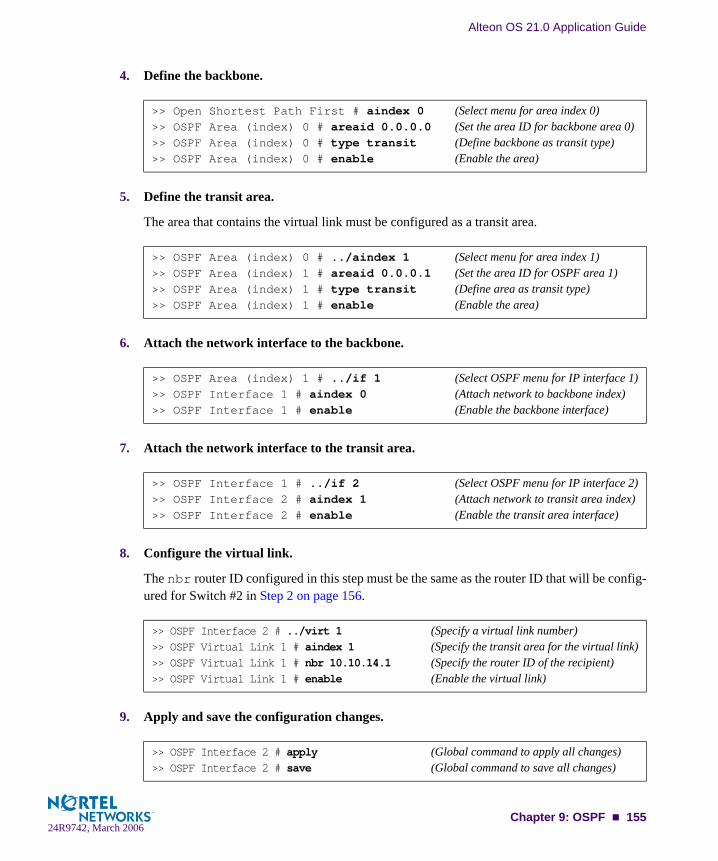
Alteon OS 21.0 Application Guide
4. Define the backbone.
5. Define the transit area.
The area that contains the virtual link must be configured as a transit area.
6. Attach the network interface to the backbone.
7. Attach the network interface to the transit area.
8. Configure the virtual link.
The nbr router ID configured in this step must be the same as the router ID that will be config-ured for Switch #2 in Step 2 on page 156.
9. Apply and save the configuration changes.
>> Open Shortest Path First # aindex 0 (Select menu for area index 0)>> OSPF Area (index) 0 # areaid 0.0.0.0 (Set the area ID for backbone area 0)>> OSPF Area (index) 0 # type transit (Define backbone as transit type)>> OSPF Area (index) 0 # enable (Enable the area)
>> OSPF Area (index) 0 # ../aindex 1 (Select menu for area index 1)>> OSPF Area (index) 1 # areaid 0.0.0.1 (Set the area ID for OSPF area 1)>> OSPF Area (index) 1 # type transit (Define area as transit type)>> OSPF Area (index) 1 # enable (Enable the area)
>> OSPF Area (index) 1 # ../if 1 (Select OSPF menu for IP interface 1)>> OSPF Interface 1 # aindex 0 (Attach network to backbone index)>> OSPF Interface 1 # enable (Enable the backbone interface)
>> OSPF Interface 1 # ../if 2 (Select OSPF menu for IP interface 2)>> OSPF Interface 2 # aindex 1 (Attach network to transit area index)>> OSPF Interface 2 # enable (Enable the transit area interface)
>> OSPF Interface 2 # ../virt 1 (Specify a virtual link number)>> OSPF Virtual Link 1 # aindex 1 (Specify the transit area for the virtual link)>> OSPF Virtual Link 1 # nbr 10.10.14.1 (Specify the router ID of the recipient)>> OSPF Virtual Link 1 # enable (Enable the virtual link)
>> OSPF Interface 2 # apply (Global command to apply all changes)>> OSPF Interface 2 # save (Global command to save all changes)
Chapter 9: OSPF 15524R9742, March 2006

Alteon OS 21.0 Application Guide
Configuring OSPF for a Virtual Link on Switch #2
1. Configure IP interfaces on each network that will be attached to OSPF areas.
Two IP interfaces are needed on Switch #2: one for the transit area network on 10.10.12.0/24 and one for the stub area network on 10.10.24.0/24.
2. Configure the router ID.
A router ID is required when configuring virtual links. This router ID should be the same one specified as the target virtual neighbor (nbr) on switch 1 in Step 8 on page 155.
3. Enable OSPF.
4. Define the backbone.
This version of Alteon OS requires that a backbone index be configured on the non-backbone end of the virtual link as follows:
5. Define the transit area.
>> # /cfg/l3/if 1 (Select menu for IP interface 1)>> IP Interface 1 # addr 10.10.12.2 (Set IP address on transit area net-
work)>> IP Interface 1 # mask 255.255.255.0 (Set IP mask on transit area network)>> IP Interface 1 # enable (Enable IP interface 1)>> IP Interface 1 # ../if 2 (Select menu for IP interface 2)>> IP Interface 2 # addr 10.10.24.1 (Set IP address on stub area network)>> IP Interface 2 # mask 255.255.255.0 (Set IP mask on stub area network)>> IP Interface 2 # enable (Enable IP interface 2)
>> IP Interface 2 # /cfg/l3/rtrid 10.10.14.1 (Set static router ID on switch 2)
>> IP# /cfg/l3/ospf/on (Enable OSPF on switch 2)
>> Open Shortest Path First # aindex 0 (Select the menu for area index 0)>> OSPF Area (index) 0 # areaid 0.0.0.0 (Set the area ID for OSPF area 0)>> OSPF Area (index) 0 # enable (Enable the area)
>> OSPF Area (index) 0 # ../aindex 1 (Select menu for area index 1)>> OSPF Area (index) 1 # areaid 0.0.0.1 (Set the area ID for OSPF area 1)>> OSPF Area (index) 1 # type transit (Define area as transit type)>> OSPF Area (index) 1 # enable (Enable the area)
156 Chapter 9: OSPF24R9742, March 2006

Alteon OS 21.0 Application Guide
6. Define the stub area.
7. Attach the network interface to the backbone.
8. Attach the network interface to the transit area.
9. Configure the virtual link.
The nbr router ID configured in this step must be the same as the router ID that was config-ured for switch #1 in Step 2 on page 154.
10. Apply and save the configuration changes.
Other Virtual Link OptionsYou can use redundant paths by configuring multiple virtual links.
Only the endpoints of the virtual link are configured. The virtual link path may traverse multiple routers in an area as long as there is a routable path between the endpoints.
>> OSPF Area (index) 1 # ../aindex 2 (Select the menu for area index 2)>> OSPF Area (index) 2 # areaid 0.0.0.2 (Set the area ID for OSPF area 2)>> OSPF Area (index) 2 # type stub (Define area as stub type)>> OSPF Area (index) 2 # enable (Enable the area)
>> OSPF Area (index) 2 # ../if 1 (Select OSPF menu for IP interface 1)>> OSPF Interface 1 # aindex 1 (Attach network to transit area index)>> OSPF Interface 1 # enable (Enable the transit area interface)
>> OSPF Interface 1 # ../if 2 (Select OSPF menu for IP interface 2)>> OSPF Interface 2 # aindex 2 (Attach network to stub area index)>> OSPF Interface 2 # enable (Enable the stub area interface)
>> OSPF Interface 2 # ../virt 1 (Specify a virtual link number)>> OSPF Virtual Link 1 # aindex 1 (Specify the transit area for the virtual link)>> OSPF Virtual Link 1 # nbr 10.10.10.1 (Specify the router ID of the recipient)>> OSPF Virtual Link 1 # enable (Enable the virtual link)
>> OSPF Interface 2 # apply (Global command to apply all changes)>> OSPF Interface 2 # save (Global command to save all changes)
Chapter 9: OSPF 15724R9742, March 2006

Alteon OS 21.0 Application Guide
Example 3: Summarizing RoutesBy default, ABRs advertise all the network addresses from one area into another area. Route summarization can be used for consolidating advertised addresses and reducing the perceived complexity of the network.
If the network IP addresses in an area are assigned to a contiguous subnet range, you can con-figure the ABR to advertise a single summary route that includes all the individual IP addresses within the area.
The following example shows one summary route from area 1 (stub area) injected into area 0 (the backbone). The summary route consists of all IP addresses from 36.128.192.0 through 36.128.254.255 except for the routes in the range 36.128.200.0 through 36.128.200.255.
Figure 9-7 Summarizing Routes
NOTE – You can specify a range of addresses to prevent advertising by using the hide option. In this example, routes in the range 36.128.200.0 through 36.128.200.255 are kept private.
BladeCenterBladeCenter
158 Chapter 9: OSPF24R9742, March 2006
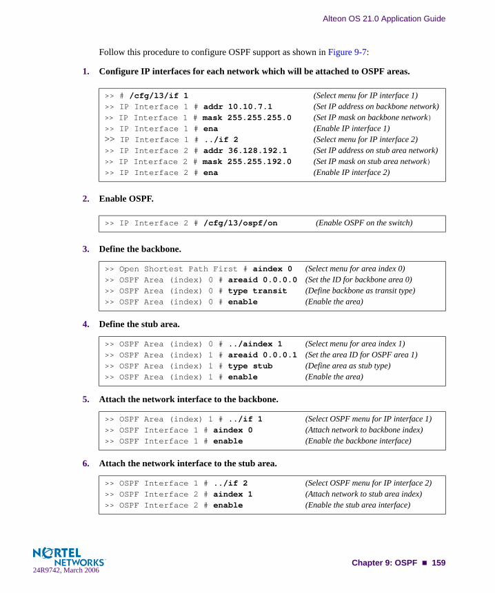
Alteon OS 21.0 Application Guide
Follow this procedure to configure OSPF support as shown in Figure 9-7:
1. Configure IP interfaces for each network which will be attached to OSPF areas.
2. Enable OSPF.
3. Define the backbone.
4. Define the stub area.
5. Attach the network interface to the backbone.
6. Attach the network interface to the stub area.
>> # /cfg/l3/if 1 (Select menu for IP interface 1)>> IP Interface 1 # addr 10.10.7.1 (Set IP address on backbone network)>> IP Interface 1 # mask 255.255.255.0 (Set IP mask on backbone network)>> IP Interface 1 # ena (Enable IP interface 1)>> IP Interface 1 # ../if 2 (Select menu for IP interface 2)>> IP Interface 2 # addr 36.128.192.1 (Set IP address on stub area network)>> IP Interface 2 # mask 255.255.192.0 (Set IP mask on stub area network)>> IP Interface 2 # ena (Enable IP interface 2)
>> IP Interface 2 # /cfg/l3/ospf/on (Enable OSPF on the switch)
>> Open Shortest Path First # aindex 0 (Select menu for area index 0)>> OSPF Area (index) 0 # areaid 0.0.0.0 (Set the ID for backbone area 0)>> OSPF Area (index) 0 # type transit (Define backbone as transit type)>> OSPF Area (index) 0 # enable (Enable the area)
>> OSPF Area (index) 0 # ../aindex 1 (Select menu for area index 1)>> OSPF Area (index) 1 # areaid 0.0.0.1 (Set the area ID for OSPF area 1)>> OSPF Area (index) 1 # type stub (Define area as stub type)>> OSPF Area (index) 1 # enable (Enable the area)
>> OSPF Area (index) 1 # ../if 1 (Select OSPF menu for IP interface 1)>> OSPF Interface 1 # aindex 0 (Attach network to backbone index)>> OSPF Interface 1 # enable (Enable the backbone interface)
>> OSPF Interface 1 # ../if 2 (Select OSPF menu for IP interface 2)>> OSPF Interface 2 # aindex 1 (Attach network to stub area index)>> OSPF Interface 2 # enable (Enable the stub area interface)
Chapter 9: OSPF 15924R9742, March 2006

Alteon OS 21.0 Application Guide
7. Configure route summarization by specifying the starting address and mask of the range of addresses to be summarized.
8. Use the hide command to prevent a range of addresses from advertising to the backbone.
9. Apply and save the configuration changes.
>> OSPF Interface 2 # ../range 1 (Select menu for summary range)>> OSPF Summary Range 1 # addr 36.128.192.0 (Set base IP address of summary range)>> OSPF Summary Range 1 # mask 255.255.192.0 (Set mask address for summary range)>> OSPF Summary Range 1 # aindex 0 (Inject summary route into backbone)>> OSPF Summary Range 1 # enable (Enable summary range)
>> OSPF Interface 2 # ../range 2 (Select menu for summary range)>> OSPF Summary Range 2 # addr 36.128.200.0 (Set base IP address)>> OSPF Summary Range 2 # mask 255.255.255.0 (Set mask address)>> OSPF Summary Range 2 # hide enable (Hide the range of addresses)
>> OSPF Summary Range 2 # apply (Global command to apply all changes)>> OSPF Summary Range 2 # save (Global command to save all changes)
160 Chapter 9: OSPF24R9742, March 2006
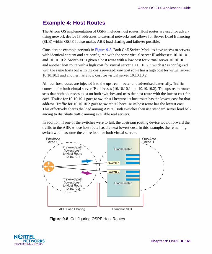
Alteon OS 21.0 Application Guide
Example 4: Host RoutesThe Alteon OS implementation of OSPF includes host routes. Host routes are used for adver-tising network device IP addresses to external networks and allows for Server Load Balancing (SLB) within OSPF. It also makes ABR load sharing and failover possible.
Consider the example network in Figure 9-8. Both GbE Switch Modules have access to servers with identical content and are configured with the same virtual server IP addresses: 10.10.10.1 and 10.10.10.2. Switch #1 is given a host route with a low cost for virtual server 10.10.10.1 and another host route with a high cost for virtual server 10.10.10.2. Switch #2 is configured with the same hosts but with the costs reversed; one host route has a high cost for virtual server 10.10.10.1 and another has a low cost for virtual server 10.10.10.2.
All four host routes are injected into the upstream router and advertised externally. Traffic comes in for both virtual server IP addresses (10.10.10.1 and 10.10.10.2). The upstream router sees that both addresses exist on both switches and uses the host route with the lowest cost for each. Traffic for 10.10.10.1 goes to switch #1 because its host route has the lowest cost for that address. Traffic for 10.10.10.2 goes to switch #2 because its host route has the lowest cost. This effectively shares the load among ABRs. Both switches then use standard server load bal-ancing to distribute traffic among available real servers.
In addition, if one of the switches were to fail, the upstream routing device would forward the traffic to the ABR whose host route has the next lowest cost. In this example, the remaining switch would assume the entire load for both virtual servers.
Figure 9-8 Configuring OSPF Host Routes
BladeCenterBladeCenter
BladeCenterBladeCenter
Switch 2Switch 2
Switch 1Switch 1
Chapter 9: OSPF 16124R9742, March 2006

Alteon OS 21.0 Application Guide
Configuring OSPF for Host Routes on GbE Switch Module #1
1. Configure IP interfaces for each network that will be attached to OSPF areas.
2. Configure basic SLB parameters.
Switch 1 is connected to two real servers. Each real server is given an IP address and is placed in the same real server group.
3. Configure client and server processing on specific ports.
4. Enable direct access mode.
>> Virtual server 1 # /cfg/l3/if 1 (Select menu for IP interface 1)>> IP Interface 1 # addr 10.10.10.5 (Set IP address on backbone network)>> IP Interface 1 # enable (Enable IP interface 1)>> IP Interface 1 # ../if 2 (Select menu for IP interface 2)>> IP Interface 2 # addr 100.100.100.40 (Set IP address on stub area network)>> IP Interface 2 # enable (Enable IP interface 2)
>> # /cfg/slb/real 1 (Select menu for real server 1)>> Real server 1 # rip 100.100.100.25 (Set the IP address for real server 1)>> Real server 1 # ena (Enable the real server)>> Real server 1 # ../real 2 (Select menu for real server 2)>> Real server 2 # rip 100.100.100.26 (Set the IP address for real server 2)>> Real server 2 # ena (Enable the real server)>> Real server 2 # ../group 1 (Select menu for real server group 1)>> Real server group 1 # add 1 (Add real server 1 to group)>> Real server group 1 # add 2 (Add real server 2 to group)>> Real server group 1 # enable (Enable the group)>> Real server group 1 # ../on (Turn SLB on)
>> Layer 4# port EXT4 (Select switch port EXT4)>> SLB Port EXT4 # client ena (Enable client processing)>> SLB Port EXT4 # ../port INT5 (Select switch Port INT5)>> SLB Port INT5 # server ena (Enable server processing)
>> Layer 4 Port INT5# ../adv (Select the SLB advance menu)>> Layer 4 Advanced# direct ena (Enable DAM)>> Layer 4 Advanced# .. (Return to the SLB menu)
162 Chapter 9: OSPF24R9742, March 2006

Alteon OS 21.0 Application Guide
5. Configure the primary virtual server.
Switch # 1 will be preferred for virtual server 10.10.10.1.
6. Configure the backup virtual server.
Switch # 1 will act as a backup for virtual server 10.10.10.2. Both virtual servers in this exam-ple are configured with the same real server group and provide identical services.
7. Enable OSPF on switch 1.
8. Define the backbone.
9. Define the stub area.
>> Layer 4 # virt 1 (Select menu for virtual server 1)>> Virtual server 1 # vip 10.10.10.1 (Set the IP address for virtual server 1)>> Virtual server 1 # ena (Enable the virtual server)>> Virtual server 1 # service http (Select menu for service on virtual server)>> Virtual server 1 http service # group 1 (Use real server group 1 for http service)
>> Virtual server 2 http service # /cfg/slb/virt 2 (Select menu for virtual server 2)>> Virtual server 1 # vip 10.10.10.2 (Set the IP address for virtual server 2)>> Virtual server 1 # ena (Enable the virtual server)>> Virtual server 1 # service http (Select menu for service on virtual server)>> Virtual server 1 # group 1 (Use real server group 1 for http service)
>> IP Interface 2 # ../ospf/on (Enable OSPF on switch 1)
>> Open Shortest Path First # aindex 0 (Select menu for area index 0)>> OSPF Area (index) 0 # areaid 0.0.0.0 (Set the ID for backbone area 0)>> OSPF Area (index) 0 # type transit (Define backbone as transit type)>> OSPF Area (index) 0 # enable (Enable the area)
>> OSPF Area (index) 0 # ../aindex 1 (Select menu for area index 1)>> OSPF Area (index) 1 # areaid 0.0.0.1 (Set the ID for stub area 1)>> OSPF Area (index) 1 # type stub (Define area as stub type)>> OSPF Area (index) 1 # enable (Enable the area)
Chapter 9: OSPF 16324R9742, March 2006

Alteon OS 21.0 Application Guide
10. Attach the network interface to the backbone.
11. Attach the network interface to the stub area.
12. Configure host routes.
One host route is needed for each virtual server on GbE Switch Module 1. Since virtual server 10.10.10.1 is preferred for switch 1, its host route has a low cost. Because virtual server 10.10.10.2 is used as a backup in case switch 2 fails, its host route has a high cost.
NOTE – You do not need to enable redistribution (cfg/l3/ospf/redist) if you configure virtual server routes as host routes.
NOTE – When a service goes down, the corresponding host route is removed from advertising.
13. Apply and save the configuration changes.
>> OSPF Area (index) 1 # ../if 1 (Select OSPF menu for IP interface 1)>> OSPF Interface 1 # aindex 0 (Attach network to backbone index)>> OSPF Interface 1 # enable (Enable the backbone interface)
>> OSPF Interface 1 # ../if 2 (Select OSPF menu for IP interface 2)>> OSPF Interface 2 # aindex 1 (Attach network to stub area index)>> OSPF Interface 2 # enable (Enable the stub area interface)
>> OSPF Interface 2 # ../host 1 (Select menu for host route 1)>> OSPF Host Entry 1 # addr 10.10.10.1 (Set IP address same as virtual server 1)>> OSPF Host Entry 1 # aindex 0 (Inject host route into backbone area)>> OSPF Host Entry 1 # cost 1 (Set low cost for preferred path)>> OSPF Host Entry 1 # enable (Enable the host route)>> OSPF Host Entry 1 # ../host 2 (Select menu for host route 2)>> OSPF Host Entry 2 # addr 10.10.10.2 (Set IP address same as virtual server 2)>> OSPF Host Entry 2 # aindex 0 (Inject host route into backbone area)>> OSPF Host Entry 2 # cost 100 (Set high cost for use as backup path)>> OSPF Host Entry 2 # enable (Enable the host route)
>> OSPF Host Entry 2 # apply (Global command to apply all changes)>> OSPF Host Entry 2 # save (Global command to save all changes)
164 Chapter 9: OSPF24R9742, March 2006
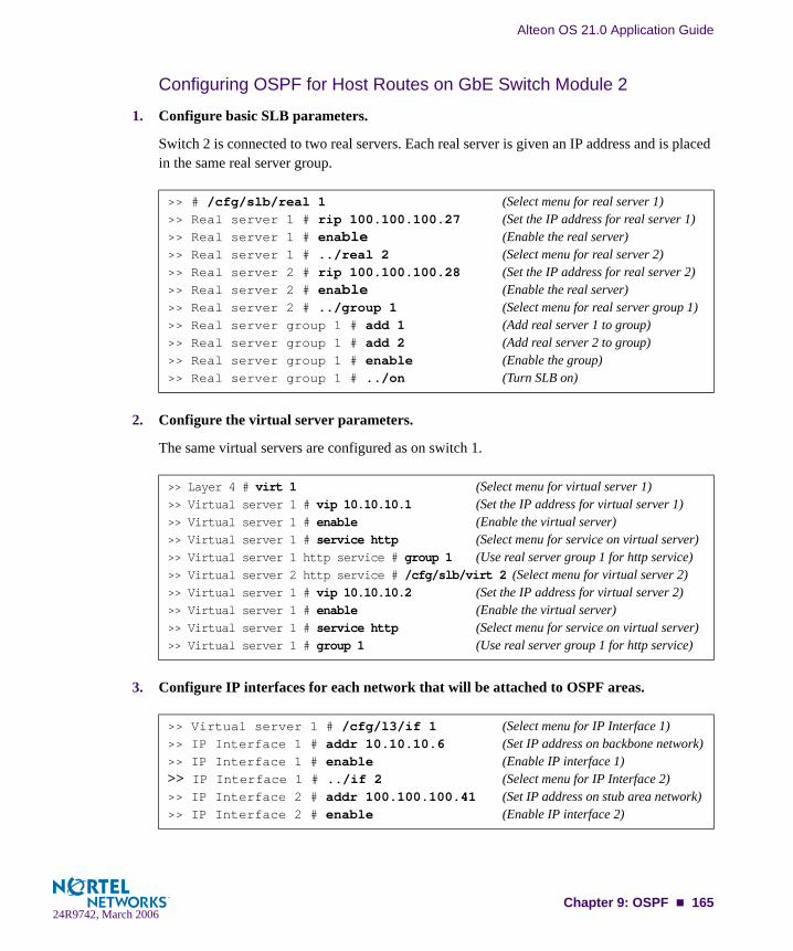
Alteon OS 21.0 Application Guide
Configuring OSPF for Host Routes on GbE Switch Module 2
1. Configure basic SLB parameters.
Switch 2 is connected to two real servers. Each real server is given an IP address and is placed in the same real server group.
2. Configure the virtual server parameters.
The same virtual servers are configured as on switch 1.
3. Configure IP interfaces for each network that will be attached to OSPF areas.
>> # /cfg/slb/real 1 (Select menu for real server 1)>> Real server 1 # rip 100.100.100.27 (Set the IP address for real server 1)>> Real server 1 # enable (Enable the real server)>> Real server 1 # ../real 2 (Select menu for real server 2)>> Real server 2 # rip 100.100.100.28 (Set the IP address for real server 2)>> Real server 2 # enable (Enable the real server)>> Real server 2 # ../group 1 (Select menu for real server group 1)>> Real server group 1 # add 1 (Add real server 1 to group)>> Real server group 1 # add 2 (Add real server 2 to group)>> Real server group 1 # enable (Enable the group)>> Real server group 1 # ../on (Turn SLB on)
>> Layer 4 # virt 1 (Select menu for virtual server 1)>> Virtual server 1 # vip 10.10.10.1 (Set the IP address for virtual server 1)>> Virtual server 1 # enable (Enable the virtual server)>> Virtual server 1 # service http (Select menu for service on virtual server)>> Virtual server 1 http service # group 1 (Use real server group 1 for http service)>> Virtual server 2 http service # /cfg/slb/virt 2 (Select menu for virtual server 2)>> Virtual server 1 # vip 10.10.10.2 (Set the IP address for virtual server 2)>> Virtual server 1 # enable (Enable the virtual server)>> Virtual server 1 # service http (Select menu for service on virtual server)>> Virtual server 1 # group 1 (Use real server group 1 for http service)
>> Virtual server 1 # /cfg/l3/if 1 (Select menu for IP Interface 1)>> IP Interface 1 # addr 10.10.10.6 (Set IP address on backbone network)>> IP Interface 1 # enable (Enable IP interface 1)>> IP Interface 1 # ../if 2 (Select menu for IP Interface 2)>> IP Interface 2 # addr 100.100.100.41 (Set IP address on stub area network)>> IP Interface 2 # enable (Enable IP interface 2)
Chapter 9: OSPF 16524R9742, March 2006

Alteon OS 21.0 Application Guide
4. Enable OSPF on switch #2.
5. Define the backbone.
6. Define the stub area.
7. Attach the network interface to the backbone.
8. Attach the network interface to the stub area.
>> IP Interface 2 # ../ospf/on (Enable OSPF on switch #2)
>> Open Shortest Path First # aindex 0 (Select menu for area index 0)>> OSPF Area (index) 0 # areaid 0.0.0.0 (Set the ID for backbone area 0)>> OSPF Area (index) 0 # type transit (Define backbone as transit type)>> OSPF Area (index) 0 # enable (Enable the area)
>> OSPF Area (index) 0 # ../aindex 1 (Select menu for area index 1)>> OSPF Area (index) 1 # areaid 0.0.0.1 (Set the ID for stub area 1)>> OSPF Area (index) 1 # type stub (Define area as stub type)>> OSPF Area (index) 1 # enable (Enable the area)
>> OSPF Area (index) 1 # ../if 1 (Select OSPF menu for IP interface 1)>> OSPF Interface 1 # aindex 0 (Attach network to backbone index)>> OSPF Interface 1 # enable (Enable the backbone interface)
>> OSPF Interface 1 # ../if 2 (Select OSPF menu for IP interface 2)>> OSPF Interface 2 # aindex 1 (Attach network to stub area index)>> OSPF Interface 2 # enable (Enable the stub area interface)
166 Chapter 9: OSPF24R9742, March 2006
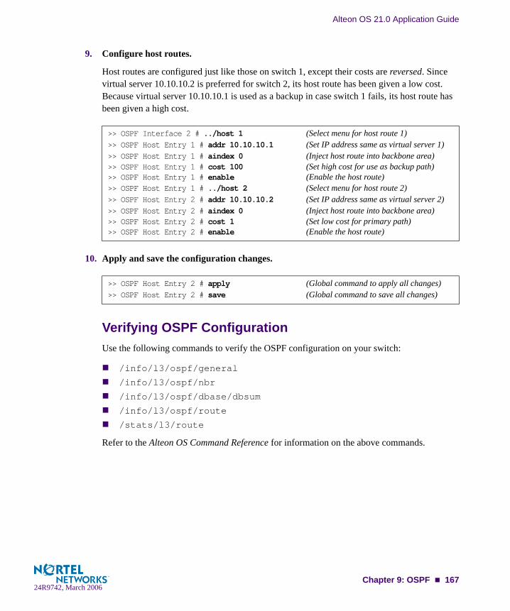
Alteon OS 21.0 Application Guide
9. Configure host routes.
Host routes are configured just like those on switch 1, except their costs are reversed. Since virtual server 10.10.10.2 is preferred for switch 2, its host route has been given a low cost. Because virtual server 10.10.10.1 is used as a backup in case switch 1 fails, its host route has been given a high cost.
10. Apply and save the configuration changes.
Verifying OSPF ConfigurationUse the following commands to verify the OSPF configuration on your switch:
/info/l3/ospf/general
/info/l3/ospf/nbr
/info/l3/ospf/dbase/dbsum
/info/l3/ospf/route
/stats/l3/route
Refer to the Alteon OS Command Reference for information on the above commands.
>> OSPF Interface 2 # ../host 1 (Select menu for host route 1)>> OSPF Host Entry 1 # addr 10.10.10.1 (Set IP address same as virtual server 1)>> OSPF Host Entry 1 # aindex 0 (Inject host route into backbone area)>> OSPF Host Entry 1 # cost 100 (Set high cost for use as backup path)>> OSPF Host Entry 1 # enable (Enable the host route)>> OSPF Host Entry 1 # ../host 2 (Select menu for host route 2)>> OSPF Host Entry 2 # addr 10.10.10.2 (Set IP address same as virtual server 2)>> OSPF Host Entry 2 # aindex 0 (Inject host route into backbone area)>> OSPF Host Entry 2 # cost 1 (Set low cost for primary path)>> OSPF Host Entry 2 # enable (Enable the host route)
>> OSPF Host Entry 2 # apply (Global command to apply all changes)>> OSPF Host Entry 2 # save (Global command to save all changes)
Chapter 9: OSPF 16724R9742, March 2006

Alteon OS 21.0 Application Guide
168 Chapter 9: OSPF24R9742, March 2006

Part 3: Application Switching Fundamentals
Internet traffic consists of myriad services and applications which use the Internet Protocol (IP) for data delivery. IP, however, is not optimized for all the various applications. Application switching goes beyond IP and makes intelligent switching decisions based on the application and its data. This sections details the following fundamental switching features:
Server Load Balancing
Filtering
Application Redirection
Health Checking
High Availability
24R9742, March 2006

Alteon OS 21.0 Application Guide
170 : Application Switching Fundamentals24R9742, March 2006

CHAPTER 10Server Load Balancing
Server Load Balancing (SLB) allows you to configure the GbE Switch Module to balance user session traffic among a pool of available servers that provide shared services. The following sections in this chapter describe how to configure and use SLB:
“Understanding Server Load Balancing” on page 172. This section discusses the benefits of server load balancing and how it works.
“Implementing Basic Server Load Balancing” on page 175. This section discusses how implementing SLB provides reliability, performance, and ease of maintenance on your network.
“Network Topology Requirements” on page 176. This section provides key require-ments to consider before deploying server load balancing.
“Configuring Server Load Balancing” on page 177.
“Additional Server Load Balancing Options” on page 182.
“Extending SLB Topologies” on page 190. This section discusses proxy IP addresses, mapping a virtual port to real ports, monitoring real server ports, and delayed binding.
“Session Initiation Protocol Server Load Balancing” on page 203.
“Workload Manager Support” on page 207.
For additional information on SLB commands, see your Alteon OS Command Reference.
24R9742, March 2006171

Alteon OS 21.0 Application Guide
Understanding Server Load BalancingSLB benefits your network in a number of ways:
Increased efficiency for server utilization and network bandwidthWith SLB, your GbE Switch Module is aware of the shared services provided by your server pool and can then balance user session traffic among the available servers. Impor-tant session traffic gets through more easily, reducing user competition for connections on overutilized servers. For even greater control, traffic is distributed according to a variety of user-selectable rules.
Increased reliability of services to users
If any server in a server pool fails, the remaining servers continue to provide access to vital applications and data. The failed server can be brought back up without interrupting access to services.
Increased scalability of services
As users are added and the server pool’s capabilities are saturated, new servers can be added to the pool transparently.
Identifying Your Network NeedsSLB may be the right option for addressing these vital network concerns:
A single server no longer meets the demand for its particular application.The connection from your LAN to your server overloads the server’s capacity.Your NT and LINUX servers hold critical application data and must remain available even in the event of a server failure.Your Web site is being used as a way to do business and for taking orders from customers. It must not become overloaded or unavailable.You want to use multiple servers or hot-standby servers for maximum server uptime.You must be able to scale your applications to meet client and LAN request capacity.You can’t afford to continue using an inferior load-balancing technique, such as DNS round robin or a software-only system.
172 Chapter 10: Server Load Balancing24R9742, March 2006
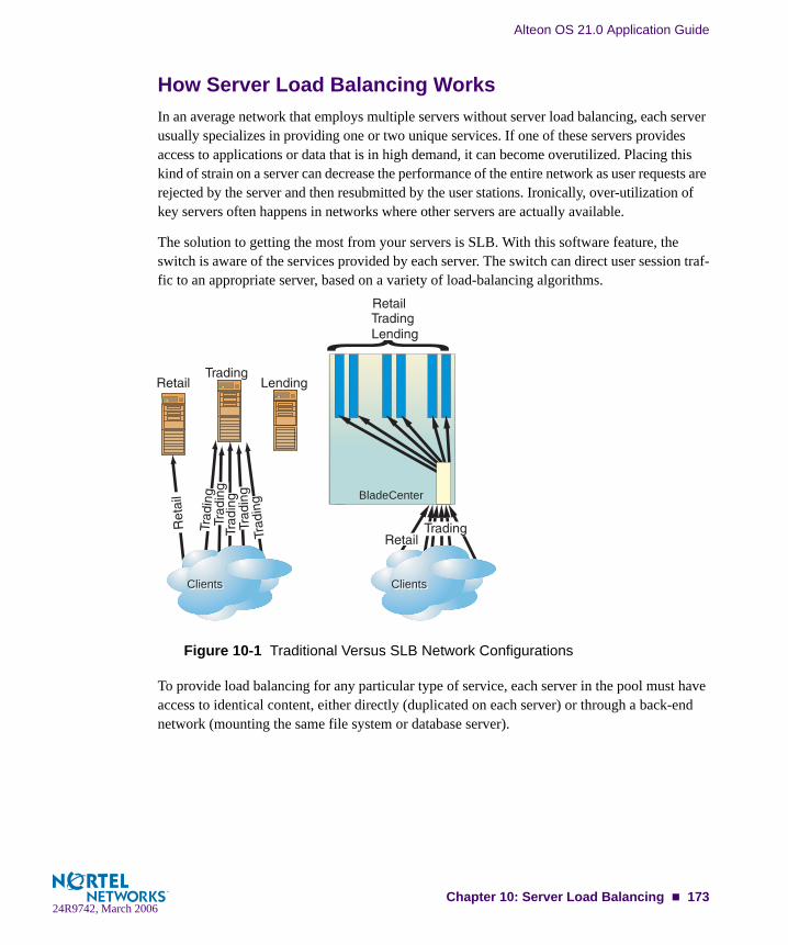
Alteon OS 21.0 Application Guide
How Server Load Balancing WorksIn an average network that employs multiple servers without server load balancing, each server usually specializes in providing one or two unique services. If one of these servers provides access to applications or data that is in high demand, it can become overutilized. Placing this kind of strain on a server can decrease the performance of the entire network as user requests are rejected by the server and then resubmitted by the user stations. Ironically, over-utilization of key servers often happens in networks where other servers are actually available.
The solution to getting the most from your servers is SLB. With this software feature, the switch is aware of the services provided by each server. The switch can direct user session traf-fic to an appropriate server, based on a variety of load-balancing algorithms.
Figure 10-1 Traditional Versus SLB Network Configurations
To provide load balancing for any particular type of service, each server in the pool must have access to identical content, either directly (duplicated on each server) or through a back-end network (mounting the same file system or database server).
ClientsClientsClientsClients
BladeCenter
BladeCenter
{
Chapter 10: Server Load Balancing 17324R9742, March 2006

Alteon OS 21.0 Application Guide
The GbE Switch Module, with SLB software, acts as a front-end to the servers, interpreting user session requests and distributing them among the available servers. Load balancing in Alteon OS can be done in the following ways:
Virtual server-based load balancing
This is the traditional load balancing method. The switch is configured to act as a virtual server and is given a virtual server IP address (or range of addresses) for each collection of services it will distribute. There can be as many as 64 virtual servers on the switch, each distributing up to four different services (up to a total of 256 services).
Each virtual server is assigned a list of the IP addresses (or range of addresses) of the real servers in the pool where its services reside. When the user stations request connections to a service, they will communicate with a virtual server on the switch. When the switch receives the request, it binds the session to the IP address of the best available real server and remaps the fields in each frame from virtual addresses to real addresses.
HTTP, IP, FTP, RTSP, IDS, and static session WAP are examples of some of the services that use virtual servers for load balancing.
Filtered-based load balancing
A filter allows you to control the types of traffic permitted through the switch. Filters are configured to allow, deny, or redirect traffic according to the IP address, protocol, or Layer 4 port criteria. In filtered-based load balancing, a filter is used to redirect traffic to a real server group. If the group is configured with more than one real server entry, redirected traffic is load balanced among the available real servers in the group.
Firewalls, WAP with RADIUS snooping, IDS, and WAN links use redirection filters to load balance traffic.
Content-based load balancing
Content-based load balancing uses Layer 7 application data (such as URL, cookies, and Host Headers) to make intelligent load balancing decisions.
URL-based load balancing, browser-smart load balancing, and cookie-based preferential load balancing are a few examples of content-based load balancing.
174 Chapter 10: Server Load Balancing24R9742, March 2006

Alteon OS 21.0 Application Guide
Implementing Basic Server Load BalancingConsider a situation where customer Web sites are being hosted by a popular Web hosting company and/or Internet Service Provider (ISP). The Web content is relatively static and is kept on a single NFS server for easy administration. As the customer base increases, the num-ber of simultaneous Web connection requests also increases.
Figure 10-2 Web Hosting Configuration Without SLB
Such a company has three primary needs:
Increased server availability
Server performance scalable to match new customer demands
Easy administration of network and servers
Figure 10-3 Web Hosting with SLB Solutions
Web Server
NFS Server
Web Clients
Internet
Web HostRouter
As clients increase, the server becomes overloaded
BladeCenterBladeCenter
InternetInternetABC
GbESM
Chapter 10: Server Load Balancing 17524R9742, March 2006
Alteon OS 21.0 Application Guide
All the issues can be addressed by adding an GbE Switch Module with SLB software.
Reliability is increased by providing multiple paths from the clients to the GbE Switch Module and by accessing a pool of servers with identical content. If one server fails, the others can take up the additional load.Performance is improved by balancing the Web request load across multiple servers. More servers can be added at any time to increase processing power.For ease of maintenance, servers can be added or removed dynamically, without interrupt-ing shared services.
Network Topology RequirementsWhen deploying SLB, there are a few key aspects to consider:
Identical content must be available to each server in the same pool. Either of these meth-ods can be used:
Static applications and data are duplicated on each real server in the pool.
Each real server in the pool has access to the same data through use of a shared file system or back-end database server.
Some services require that a series of client requests go to the same real server so that ses-sion-specific state data can be retained between connections. Services of this nature include Web search results, multi-page forms that the user fills in, or custom Web-based applications typically created using cgi-bin scripts. Connections for these types of ser-vices must be configured as persistent (see Chapter 17, “Persistence”) or must use the minmisses or hash metrics (see “Metrics for Real Server Groups” on page 185).
Clients and servers can be connected through the same switch port. Each port in use on the switch can be configured to process client requests, server traffic, or both. You can enable or disable processing on a port independently for each type of Layer 4 traffic.
Layer 4 client processing: Ports that are configured to process client request traffic provide address translation from the virtual server IP to the real server IP address.
Layer 4 server processing: Ports that are configured to process server responses to cli-ent requests provide address translation from the real server IP address to the virtual server IP address. These ports require real servers to be connected to the GbE Switch Module directly.
NOTE – Switch ports configured for Layer 4 client/server processing can simultaneously pro-vide Layer 2 switching and IP routing functions.
176 Chapter 10: Server Load Balancing24R9742, March 2006

Alteon OS 21.0 Application Guide
Consider the following network topology:
Figure 10-4 Example Network for Client/Server Port Configuration
In Figure 10-4, the switch load balances traffic to a Web server pool and to a Domain Name System (DNS) server pool. The switch port connected to the Web server pool (port 11) is asked to perform both server and client processing.
Configuring Server Load BalancingThis section describes the steps for configuring an SLB Web hosting solution. In the following procedure, many of the SLB options are left to their default values. See “Additional Server Load Balancing Options” on page 182 for more options. Before you start configuring, you must be connected to the switch CLI as the administrator.
NOTE – For details about any of the menu commands described in this example, see your Alteon OS Command Reference.
1. Assign an IP address to each of the real servers in the server pool.
The real servers in any given real server group must have an IP route to the switch that per-forms the SLB functions. This IP routing is most easily accomplished by placing the switches and servers on the same IP subnet, although advanced routing techniques can be used as long as they do not violate the topology rules outlined in “Network Topology Requirements” on page 176.
InternetInternet
BladeCenter
SS CC
SSCC
Web servers initiate DNS requests,which are load balanced to DNS servers
Clients on the Internetinitiate HTTP sessions, which are load balanced to Web servers
CC
SS
Client Processing
Server Processing
GbESM
Chapter 10: Server Load Balancing 17724R9742, March 2006
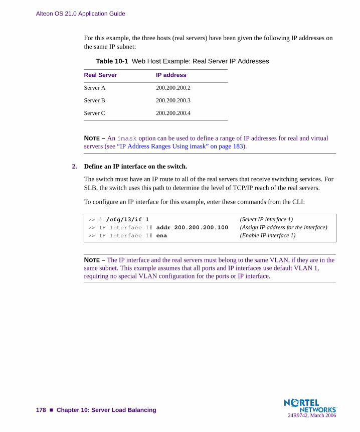
Alteon OS 21.0 Application Guide
For this example, the three hosts (real servers) have been given the following IP addresses on the same IP subnet:
NOTE – An imask option can be used to define a range of IP addresses for real and virtual servers (see “IP Address Ranges Using imask” on page 183).
2. Define an IP interface on the switch.
The switch must have an IP route to all of the real servers that receive switching services. For SLB, the switch uses this path to determine the level of TCP/IP reach of the real servers.
To configure an IP interface for this example, enter these commands from the CLI:
NOTE – The IP interface and the real servers must belong to the same VLAN, if they are in the same subnet. This example assumes that all ports and IP interfaces use default VLAN 1, requiring no special VLAN configuration for the ports or IP interface.
Table 10-1 Web Host Example: Real Server IP Addresses
Real Server IP address
Server A 200.200.200.2
Server B 200.200.200.3
Server C 200.200.200.4
>> # /cfg/l3/if 1 (Select IP interface 1)>> IP Interface 1# addr 200.200.200.100 (Assign IP address for the interface)>> IP Interface 1# ena (Enable IP interface 1)
178 Chapter 10: Server Load Balancing24R9742, March 2006

Alteon OS 21.0 Application Guide
3. Define each real server.
For each real server, you must assign a real server number, specify its actual IP address, and enable the real server. For example:
4. Define a real server group and add the three real servers to the service group.
5. Define a virtual server.
All client requests will be addressed to a virtual server IP address on a virtual server defined on the switch. Clients acquire the virtual server IP address through normal DNS resolution. In this example, HTTP is configured as the only service running on this virtual server, and this service is associated with the real server group. For example:
NOTE – This configuration is not limited to HTTP Web service. Other TCP/IP services can be configured in a similar fashion. For a list of other well-known services and ports, see “Well-Known Application Ports” on page 182. To configure multiple services, see “Configuring Mul-tiple Services” on page 184.
>> IP Interface 1# /cfg/slb/real 1 (Server A is real server 1)>> Real server 1# rip 200.200.200.2 (Assign Server A IP address)>> Real server 1# ena (Enable real server 1)>> Real server 1# ../real 2 (Server B is real server 2)>> Real server 2# rip 200.200.200.3 (Assign Server B IP address)>> Real server 2# ena (Enable real server 2)>> Real server 2# ../real 3 (Server C is real server 3)>> Real server 3# rip 200.200.200.4 (Assign Server C IP address)>> Real server 3# ena (Enable real server 3)
>> Real server 3# /cfg/slb/group 1 (Select real server group 1)>> Real server group 1# add 1 (Add real server 1 to group 1)>> Real server group 1# add 2 (Add real server 2 to group 1)>> Real server group 1# add 3 (Add real server 3 to group 1)
>> Real server group 1# /cfg/slb/virt 1 (Select virtual server 1)>> Virtual server 1# vip 200.200.200.1 (Assign a virtual server IP address)>> Virtual server 1# ena (Enable the virtual server)>> Virtual server 1# service http (Select the HTTP service menu)>> Virtual server 1 http Service# group 1 (Associate virtual port to real group)
Chapter 10: Server Load Balancing 17924R9742, March 2006
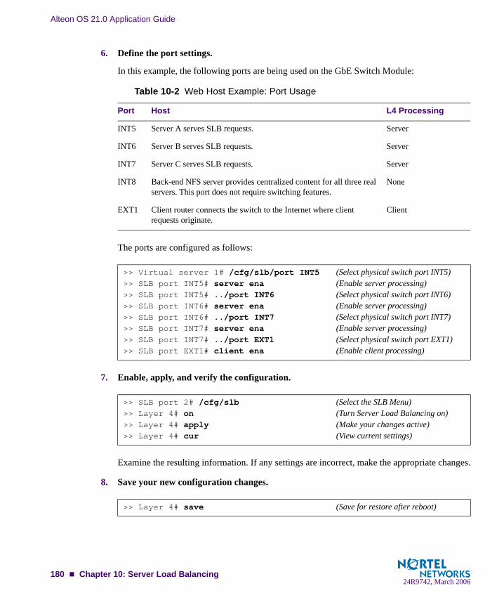
Alteon OS 21.0 Application Guide
6. Define the port settings.
In this example, the following ports are being used on the GbE Switch Module:
The ports are configured as follows:
7. Enable, apply, and verify the configuration.
Examine the resulting information. If any settings are incorrect, make the appropriate changes.
8. Save your new configuration changes.
Table 10-2 Web Host Example: Port Usage
Port Host L4 Processing
INT5 Server A serves SLB requests. Server
INT6 Server B serves SLB requests. Server
INT7 Server C serves SLB requests. Server
INT8 Back-end NFS server provides centralized content for all three real servers. This port does not require switching features.
None
EXT1 Client router connects the switch to the Internet where client requests originate.
Client
>> Virtual server 1# /cfg/slb/port INT5 (Select physical switch port INT5)>> SLB port INT5# server ena (Enable server processing)>> SLB port INT5# ../port INT6 (Select physical switch port INT6)>> SLB port INT6# server ena (Enable server processing)>> SLB port INT6# ../port INT7 (Select physical switch port INT7)>> SLB port INT7# server ena (Enable server processing)>> SLB port INT7# ../port EXT1 (Select physical switch port EXT1)>> SLB port EXT1# client ena (Enable client processing)
>> SLB port 2# /cfg/slb (Select the SLB Menu)>> Layer 4# on (Turn Server Load Balancing on)>> Layer 4# apply (Make your changes active)>> Layer 4# cur (View current settings)
>> Layer 4# save (Save for restore after reboot)
180 Chapter 10: Server Load Balancing24R9742, March 2006

Alteon OS 21.0 Application Guide
NOTE – You must apply any changes in order for them to take effect, and you must save changes if you wish them to remain in effect after switch reboot.
9. Check the SLB information.
Check that all SLB parameters are working according to expectation. If necessary, make any appropriate configuration changes and then check the information again.
>> Layer 4# /info/slb/dump (View SLB information)
Chapter 10: Server Load Balancing 18124R9742, March 2006

Alteon OS 21.0 Application Guide
Additional Server Load Balancing OptionsIn the previous section (“Configuring Server Load Balancing” on page 177), many of the SLB options are left to their default values. The following configuration options can be used to cus-tomize SLB on your GbE Switch Module:
“Supported Services and Applications” on page 182“Disabling and Enabling Real Servers” on page 183“IP Address Ranges Using imask” on page 183“Health Checks for Real Servers” on page 184“Configuring Multiple Services” on page 184“Metrics for Real Server Groups” on page 185“Weights for Real Servers” on page 188“Connection Time-outs for Real Servers” on page 188“Maximum Connections for Real Servers” on page 188“Backup/Overflow Servers” on page 189
Supported Services and ApplicationsEach virtual server can be configured to support up to four services, limited to a total of 256 services per switch. Using the /cfg/slb/virt <virtual server number>/service option, the following TCP/UDP applications can be specified:
NOTE – The service number specified on the switch must match the service specified on the server.
Table 10-3 Well-Known Application Ports
Number TCP/UDPApplication
Number TCP/UDPApplication
Number TCP/UDPApplication
202122232537424349536970
ftp-dataftpsshtelnetsmtptimenamewhoisTACACS+domaintftpgopher
7980109110111119123143144161162
fingerhttppop2pop3sunrpcnntpntpimapnewssnmpsnmptrap
1791942203894435205541645, 181218131985
bgpircimap3ldaphttpsriprtspRadiusRadius Accountinghsrp
182 Chapter 10: Server Load Balancing24R9742, March 2006
Alteon OS 21.0 Application Guide
NOTE – Load balancing some applications (such as FTP and RTSP) require special configura-tion.
Disabling and Enabling Real ServersIf you need to reboot a server, make sure that new sessions are not sent to the real server and that old sessions are not discarded. When the session count reaches zero, you may shut down the server. Use the following command to disable real servers:
When maintenance is complete, use the following command to enable the real server:
IP Address Ranges Using imaskThe imask option lets you define a range of IP addresses for the real and virtual servers con-figured under SLB. By default, the imask setting is 255.255.255.255, which means that each real and virtual server represents a single IP address. An imask setting of 255.255.255.0 would mean that each real and virtual server represents 256 IP addresses. Consider the following example:
A virtual server is configured with an IP address of 172.16.10.1.
Real servers 172.16.20.1 and 172.16.30.1 are assigned to service the virtual server.
The imask is set to 255.255.255.0.
If the client request was sent to virtual server IP address 172.16.10.45, the unmasked portion of the address (0.0.0.45) gets mapped directly to whichever real server IP address is selected by the SLB algorithm. Thus, the request would be sent to either 172.16.20.45 or 172.16.30.45.
>> # /oper/slb/dis <real server number>
>> # /oper/slb/ena <real server number>
Chapter 10: Server Load Balancing 18324R9742, March 2006

Alteon OS 21.0 Application Guide
Health Checks for Real ServersDetermining health for each real server is a necessary function for SLB. By default for TCP services, the switch checks health by opening a TCP connection to each service port config-ured as part of each service. For more information, see “Configuring Multiple Services” on page 184. For UDP services, the switch pings servers to determine their status.
The switch checks each service on each real server every two seconds. If the real server is busy processing connections, it may not respond to a health check. By default, if a service does not respond to four consecutive health checks, the switch declares the service unavailable. As shown below, the health check interval and the number of retries can be changed:
For more complex health-checking strategies, see Chapter 14, “Health Checking.”
Configuring Multiple ServicesWhen you configure multiple services in the same group, their health checks will be dependent on each other. If a real server fails a health check for a service, then the status of the real server for the second service appears as “blocked.”
Independent Services. If you are configuring two independent services such as FTP and SMTP—where the real server failure on one service does not affect other services that the real server supports, then configure two groups with the same real servers, but with different ser-vices. If a real server configured for both FTP and SMTP fails FTP, the real server is still avail-able for SMTP. This allows the services to act independently even though they are using the same real servers.
Dependent Services. If you are configuring two dependent services such as HTTP and HTTPS—where the real server failure on one service blocks the real server for other services, then configure a single group with multiple services. If a real server configured for both HTTP and HTTPS fails for the HTTP service, then the server is blocked from supporting any HTTPS requests. The switch will block HTTPS requests, (even though HTTPS has not failed) until the HTTP service becomes available again. This helps in troubleshooting so you know which ser-vice has failed.
>> # /cfg/slb/real <real server number> (Select the real server)>> Real server# inter 4 (Check real server every 4 seconds)>> Real server# retry 6 (Declare down after 6 checks fail)
184 Chapter 10: Server Load Balancing24R9742, March 2006
Alteon OS 21.0 Application Guide
Metrics for Real Server GroupsMetrics are used for selecting which real server in a group will receive the next client connec-tion. The available metrics minmisses (minimum misses), hash, leastconns (least con-nections), roundrobin, bandwidth, and response (response time) are explained in detail below. The default metric is leastconns.
To change a real server group metric to minmisses, for example, enter:
Minimum Misses
The minmisses metric is optimized for application redirection. It uses IP address information in the client request to select a server. When selecting a server, the switch calculates a value for each available real server based on the relevant IP address information. The server with highest value is assigned the connection. This metric attempts to minimize the disruption of persis-tency when servers are removed from service. This metric should be used only when persis-tence is a must.
By default the minmiss algorithm uses the upper 24-bits of the source IP address to calculate the real server that the traffic should be sent to when the minmiss metric is selected. In Alteon OS 21.0 you can select all the 32-bits of the source IP address to hash to the real server.
The source or destination IP address information used depends on the application:
For application redirection, the client destination IP address is used. All requests for a spe-cific IP destination address are sent to the same server. This metric is particularly useful in caching applications, helping to maximize successful cache hits. Best statistical load bal-ancing is achieved when the IP address destinations of load-balanced frames are spread across a broad range of IP subnets.
For SLB, the client source IP address and real server IP address are used. All requests from a specific client are sent to the same server. This metric is useful for applications where client information must be retained on the server between sessions. With this met-ric, server load becomes most evenly balanced as the number of active clients with differ-ent source or destination addresses increases.
To select all 32-bits of the source IP address, use the command, /cfg/slb/group x/mhash 32. This 32-bit hash is most useful in the wireless world.
The minmisses metric cannot be used for firewall load balancing, since the real server IP addresses used in calculating the score for this metric are different on each side of the firewall.
>> # /cfg/slb/group <group number> (Select the real server group)>> Real server group# metric minmisses (Use minmisses metric)
Chapter 10: Server Load Balancing 18524R9742, March 2006

Alteon OS 21.0 Application Guide
Hash
The hash metric uses IP address information in the client request to select a server. The spe-cific IP address information used depends on the application:
For Application Redirection, the client destination IP address is used. All requests for a specific IP destination address will be sent to the same server. This is particularly useful for maximizing successful cache hits.
For SLB, the client source IP address is used. All requests from a specific client will be sent to the same server. This option is useful for applications where client information must be retained between sessions.
For FWLB, both the source and destination IP addresses are used to ensure that the two unidirectional flows of a given session are redirected to the same firewall.
When selecting a server, a mathematical hash of the relevant IP address information is used as an index into the list of currently available servers. Any given IP address information will always have the same hash result, providing natural persistence, as long as the server list is sta-ble. However, if a server is added to or leaves the mix, then a different server might be assigned to a subsequent session with the same IP address information even though the original server is still available. Open connections are not cleared.
NOTE – The hash metric provides more distributed load balancing than minmisses at any given instant. It should be used if the statistical load balancing achieved using minmisses is not as optimal as desired. If the load balancing statistics with minmisses indicate that one server is processing significantly more requests over time than other servers, consider using the hash metric.
Least Connections
With the leastconns metric, the number of connections currently open on each real server is measured in real time. The server with the fewest current connections is considered to be the best choice for the next client connection request.
This option is the most self-regulating, with the fastest servers typically getting the most con-nections over time.
Round Robin
With the roundrobin metric, new connections are issued to each server in turn; that is, the first real server in the group gets the first connection, the second real server gets the next con-nection, followed by the third real server, and so on. When all the real servers in this group have received at least one connection, the issuing process starts over with the first real server.
186 Chapter 10: Server Load Balancing24R9742, March 2006

Alteon OS 21.0 Application Guide
Response Time
The response metric uses real server response time to assign sessions to servers. The response time between the servers and the switch is used as the weighting factor. The switch monitors and records the amount of time it takes for each real server to reply to a health check to adjust the real server weights. The weights are adjusted so they are inversely proportional to a moving average of response time. In such a scenario, a server with half the response time as another server will receive a weight twice as large.
NOTE – The effects of the response weighting apply directly to the real servers and are not necessarily confined to the real server group. When response time-metered real servers are also used in other real server groups that use the leastconns or roundrobin metrics, the response weights are applied on top of the leastconns or roundrobin calculations for the affected real servers. Since the response weight changes dynamically, this can pro-duce fluctuations in traffic distribution for the real server groups that use the leastconns or roundrobin metrics.
Bandwidth
The bandwidth metric uses real server octet counts to assign sessions to a server. The switch monitors the number of octets sent between the server and the switch. Then, the real server weights are adjusted so they are inversely proportional to the number of octets that the real server processes during the last interval.
Servers that process more octets are considered to have less available bandwidth than servers that have processed fewer octets. For example, the server that processes half the amount of octets over the last interval receives twice the weight of the other servers. The higher the band-width used, the smaller the weight assigned to the server. Based on this weighting, the subse-quent requests go to the server with the highest amount of free bandwidth. These weights are automatically assigned.
The bandwidth metric requires identical servers with identical connections.
NOTE – The effects of the bandwidth weighting apply directly to the real servers and are not necessarily confined to the real server group. When bandwidth-metered real servers are also used in other real server groups that use the leastconns or roundrobin metrics, the bandwidth weights are applied on top of the leastconns or round-robin calculations for the affected real servers. Since the bandwidth weight changes dynamically, this can pro-duce fluctuations in traffic distribution for the real server groups that use the leastconns or roundrobin metrics.
Chapter 10: Server Load Balancing 18724R9742, March 2006

Alteon OS 21.0 Application Guide
Weights for Real ServersWeights can be assigned to each real server. These weights can bias load balancing to give the fastest real servers a larger share of connections. Weight is specified as a number from 1 to 48. Each increment increases the number of connections the real server gets. By default, each real server is given a weight setting of 1. A setting of 10 would assign the server roughly 10 times the number of connections as a server with a weight of 1. To set weights, enter the following commands:
NOTE – Weights are not applied when using the hash or minmisses metrics.
Connection Time-outs for Real ServersIn some cases, open TCP/IP sessions might not be closed properly (for example, the switch receives the SYN for the session, but no FIN is sent). If a session is inactive for 10 minutes (the default), it is removed from the session table in the switch. To change the time-out period, enter the following:
The example above would change the time-out period of all connections on the designated real server to four minutes.
Maximum Connections for Real ServersYou can set the number of open connections each real server is allowed to handle for SLB. To set the connection limit, enter the following:
Values average from approximately 500 HTTP connections for slower servers to 1500 for quicker, multiprocessor servers. The appropriate value also depends on the duration of each session and how much CPU capacity is occupied by processing each session. Connections that use a lot of Java or CGI scripts for forms or searches require more server resources and thus a lower maxcon limit. You may wish to use a performance benchmark tool to determine how many connections your real servers can handle.
When a server reaches its maxcon limit, the switch no longer sends new connections to the server. When the server drops back below the maxcon limit, new sessions are again allowed.
>> # /cfg/slb/real <real server number> (Select the real server)>> Real server# weight 10 (10 times the number of connections)
>> # /cfg/slb/real <real server number> (Select the real server)>> Real server# tmout 4 (Specify an even numbered interval)
>> # /cfg/slb/real <real server number> (Select the real server)>> Real server# maxcon 1600 (Allow 1600 connections maximum)
188 Chapter 10: Server Load Balancing24R9742, March 2006

Alteon OS 21.0 Application Guide
Backup/Overflow ServersA real server can backup other real servers and can handle overflow traffic when the maximum connection limit is reached. Each backup real server must be assigned a real server number and real server IP address. It must then be enabled. Finally, the backup server must be assigned to each real server that it will back up. The following defines real server 4 as a backup for real servers 1 and 2:
In a similar fashion, a backup/overflow server can be assigned to a real server group. If all real servers in a real server group fail or overflow, the backup comes online.
Real server groups can also use another real server group for backup/overflow:
>> # /cfg/slb/real 4 (Select real server 4 as backup)>> Real server 4# rip 200.200.200.5 (Assign backup IP address)>> Real server 4# ena (Enable real server 4)>> Real server 4# /cfg/slb/real 1 (Select real server 1)>> Real server 1# backup 4 (Real server 4 is backup for 1)>> Real server 1# /cfg/slb/real 2 (Select real server 2)>> Real server 2# backup 4 (Real server 4 is backup for 2)
>> # /cfg/slb/group <real server group number> (Select real server group)>> Real server group# backup r4 (Assign real server 4 as backup)
>> # /cfg/slb/group <real server group number> (Select real server group)>> Real server group# backup g2 (Assign real server group 2 as
backup)
Chapter 10: Server Load Balancing 18924R9742, March 2006
Alteon OS 21.0 Application Guide
Extending SLB TopologiesFor standard SLB, all client-to-server requests to a particular virtual server and all related server-to-client responses must pass through the same GbE Switch Module. In complex net-work topologies, routers and other devices can create alternate paths around the GbE Switch Module (GbESM) managing SLB functions. Under such conditions, the GbESM with Alteon OS provides the following solutions:
Proxy IP Addresses Mapping Ports Direct Server Interaction Delayed Binding
Proxy IP AddressesIn complex network topologies, SLB functions can be managed using a proxy IP address on the client switch ports.
When the client requests services from the switch’s virtual server, the client sends its own IP address for use as a return address. If a proxy IP address is configured for the client port on the switch, the switch replaces the client’s source IP address with the switch’s own proxy IP address before sending the request to the real server. This creates the illusion that the switch originated the request.
The real server uses the switch’s proxy IP address as the destination address for any response. SLB traffic is forced to return through the proper switch, regardless of alternate paths. Once the switch receives the proxied data, it puts the original client IP address into the destination address and sends the packet to the client. This process is transparent to the client.
NOTE – Because requests appear to come from the switch proxy IP address rather than the cli-ent source IP address, the network administrator should be aware of this behavior during debugging and statistics collection.
The proxy IP address can also be used for direct access to the real servers (see “Direct Server Interaction” on page 196).
Proxy IP Address and VMAWith VMA enabled, the concept of a global session table exists on the GbE Switch Module. To identify which processor should process responses to proxied requests, a unique proxy IP address must be configured. If VMA is disabled, refer to Table 10-4 to configure the corre-sponding proxy IP for the port and enable proxy.
190 Chapter 10: Server Load Balancing24R9742, March 2006

Alteon OS 21.0 Application Guide
Table 10-4 show the different ports sharing proxy IP addresses. For example, port numbers 1, 3, 5 and port 19 share proxy IP address 1. Alteon OS requires you to configure two proxy IP addresses. The unused proxy IP address can be disabled using the command /cfg/slb/port x/proxy dis.
Frames ingressing a port that has proxy option enabled (/cfg/slb/port x/proxy ena) are processed using one of the configured proxy IP addresses. The source IP address determines which proxy IP address to use. The client source address is substituted with the proxy IP address of the port processing the request. If proxy is disabled, then the client IP address is not replaced with a proxy IP address.
Table 10-4 Proxy IP addresses on GbE Switch Module
Proxy IP addresses Gig port numbers
Proxy IP address 1 Odd-numbered ports
Proxy IP address 2 Even-numbered ports
>> # /cfg/slb/pip/pip1 10.10.10.10 (Configure a proxy IP address)>> # /cfg/slb/port EXT1/proxy ena (Enable proxy on port EXT1)>> # /cfg/slb/port INT1/proxy dis (Disable proxy on port INT1)>> # /cfg/slb/port INT2/proxy dis (Disable proxy on port INT2)>> # /cfg/slb/port INT3/proxy dis (Disable proxy on port INT3)>> # /cfg/slb/port INT4/proxy dis (Disable proxy on port INT4)and so on....
Chapter 10: Server Load Balancing 19124R9742, March 2006
Alteon OS 21.0 Application Guide
The following procedure can be used for configuring proxy IP addresses:
1. Disable server processing on affected switch ports.
When implementing proxies, switch ports can be reconfigured to disable server processing. Referring to the Table 10-2 on page 180, the following revised port conditions are used:
The following commands are used to disable server processing on ports 5-7:
2. Configure a unique proxy address and enable proxy for the client ports.
Configure a unique proxy IP address and enable proxy on the client ports:
The proxies are transparent to the user.
3. (optional) If the Virtual Matrix Architecture (VMA) feature is enabled, configure all proxy IP addresses.
Table 10-5 Proxy Example: Port Usage
Port Host L4 Processing
INT5 Server A None
INT6 Server B None
INT7 Server C None
INT8 Back-end NFS server provides centralized content for all three real servers. This port does not require switching features.
None
EXT1 Client router connects the switch to the Internet where all client requests originate.
Client
>> # /cfg/slb/port INT5 (Select switch port INT5)>> SLB port INT5# server dis (Disable server processing)>> SLB port INT5# ../port INT6 (Select switch port INT6)>> SLB port INT6# server dis (Disable server processing)>> SLB port INT6# ../port INT7 (Select switch port INT7)>> SLB port INT7# server dis (Disable server processing)
>> SLB port INT7# ../pip (Select proxy IP menu)>> Proxy IP Address# pip1 200.200.200.68 (Set proxy IP address)>> # /cfg/slb/port EXT1/proxy ena (Select network port and enable proxy)>> SLB port EXT1# ../port EXT2 (Select network port EXT2)>> SLB port EXT2# proxy ena (Enable proxy)
192 Chapter 10: Server Load Balancing24R9742, March 2006

Alteon OS 21.0 Application Guide
VMA is normally enabled on the switch. In addition to enhanced resource management, VMA eliminates many of the restrictions found in earlier versions of the Alteon OS. VMA does require, that you configure two unique proxy IP addresses.
The following commands can be used for configuring the additional proxy IP address:
For information on using the VMA commands, see the Alteon OS Command Reference (/cfg/slb/adv/matrix) for more information.
4. Apply and save your changes.
NOTE – Remember that you must apply any changes in order for them to take effect, and you must save them if you wish them to remain in effect after switch reboot. Also, the /info/slb command is useful for checking the state of Server Load Balancing operations.
Mapping PortsA GbE Switch Module allows you to hide the identity of a port for security by mapping a vir-tual server port to a different real server port.
Mapping a Virtual Server Port to a Real Server PortIn addition to providing direct real server access in some situations (see “Mapping Ports” on page 198), mapping is required when administrators choose to execute their real server pro-cesses on different ports than the well-known TCP/UDP ports. Otherwise, virtual server ports are mapped directly to real server ports by default and require no mapping configuration.
Port mapping is configured from the Virtual Server Services menu. For example, to map the virtual server TCP/UDP port 80 to real server TCP/UDP port 8004, you could enter the follow-ing:
NOTE – If filtering is enabled, a proxy IP address is configured, or URL parsing is enabled on any switch port, then port mapping is supported with Direct Access Mode (DAM). For infor-mation about DAM, refer to “Using Direct Access Mode” on page 196.
>> SLB port 2# ../pip (Select the proxy IP address menu)>> Proxy IP Address# pip2 200.200.200.69 (Set proxy IP address)
>> # /cfg/slb/virt 1/service 80 (Select virtual server port 80)>> Virtual Server 1 http Service# rport 8004 (Map to real port 8004)
Chapter 10: Server Load Balancing 19324R9742, March 2006
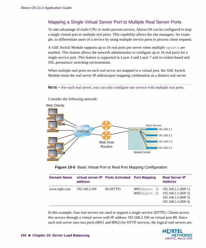
Alteon OS 21.0 Application Guide
Mapping a Single Virtual Server Port to Multiple Real Server PortsTo take advantage of multi-CPU or multi-process servers, Alteon OS can be configured to map a single virtual port to multiple real ports. This capability allows the site managers, for exam-ple, to differentiate users of a service by using multiple service ports to process client requests.
A GbE Switch Module supports up to 16 real ports per server when multiple rports are enabled. This feature allows the network administrator to configure up to 16 real ports for a single service port. This feature is supported in Layer 4 and Layer 7 and in cookie-based and SSL persistence switching environments.
When multiple real ports on each real server are mapped to a virtual port, the GbE Switch Module treats the real server IP address/port mapping combination as a distinct real server.
NOTE – For each real server, you can only configure one service with multiple real ports.
Consider the following network:
Figure 10-5 Basic Virtual Port to Real Port Mapping Configuration
In this example, four real servers are used to support a single service (HTTP). Clients access this service through a virtual server with IP address 192.168.2.100 on virtual port 80. Since each real server uses two ports (8001 and 8002) for HTTP services, the logical real servers are:
Domain Name virtual server IP address
Ports Activated Port Mapping Real Server IP Address
www.right.com 192.168.2.100 80 (HTTP) 8001 (rport 1)8002 (rport 2)
192.168.2.1 (RIP 1)192.168.2.2 (RIP 2)192.168.2.3 (RIP 3)192.168.2.4 (RIP 4)
BladeCenterBladeCenter
InternetInternet
Real Servers192.168.2.1
192.168.2.2
192.168.2.3
192.168.2.4
GbESM
194 Chapter 10: Server Load Balancing24R9742, March 2006

Alteon OS 21.0 Application Guide
192.168.2.1/8001192.168.2.1/8002192.168.2.2/8001192.168.2.2/8002 192.168.2.3/8001192.168.2.3/8002192.168.2.4/8001192.168.2.4/8002
Load Balancing Metric
For each service, a real server is selected using the configured load balancing metric (hash, leastconns, minmisses, or roundrobin). To ensure even distribution, once an avail-able server is selected, the switch will use the roundrobin metric to choose a real port to receive the incoming connection.
If the algorithm is leastconns, the switch sends the incoming connections to the logical real server (real server IP address/port combination) with the least number of connections.
The /cfg/slb/virt command defines the real server TCP or UDP port assigned to a ser-vice. By default, this is the same as the virtual port (service virtual port). If rport is config-ured to be different from the virtual port defined in /cfg/slb/virt <virtual server number>/service <virtual port>, the switch maps the virtual port to the real port.
NOTE – To use the single virtual port to multiple rport feature, configure this real server port option to be a value of 0. However, note that you cannot configure multiple services with mul-tiple rports in the same server if the multiple rport feature is enabled.
Configuring Multiple Service Ports
Two commands, addport and remport, under the real server menu allow users to add or remove multiple service ports associated with a particular server. (A service port is a TCP or UDP port number.) For example: addport 8001 and remport 8001.
1. Configure the real servers.
>> # /cfg/slb/real 1/rip 192.168.2.1/ena>> # ../real 2/rip 192.168.2.2/ena>> # ../real 3/rip 192.168.2.3/ena>> # ../real 4/rip 192.168.2.4/ena
Chapter 10: Server Load Balancing 19524R9742, March 2006

Alteon OS 21.0 Application Guide
2. Add all four servers to a group.
3. Configure a virtual server IP address.
4. Turn on multiple rport for Port 80.
5. Add the ports to which the Web server listens.
Direct Server InteractionDirect access to real servers can be provided in the following ways:
Using Direct Access Mode Assigning Multiple IP Addresses Using Proxy IP Addresses Mapping Ports Monitoring Real Servers
Using Direct Access ModeWhen Direct Access Mode (DAM) (/cfg/slb/adv/direct) is enabled on a switch, any client can communicate with any real server’s load-balanced service. Also, with DAM enabled, any number of virtual services can be configured to load balance a real service.
>> # /cfg/slb/group 1>> Real server Group 1# add 1>> Real server Group 1# add 2>> Real server Group 1# add 3>> Real server Group 1# add 4
>> # /cfg/slb/virt 1/vip 192.168.2.100/ena
>> # /cfg/slb/virt 1/service 80/rport 0
>> # /cfg/slb/real 1/addport 8001 (Add port 8001 to real server 1)>> # addport 8002 (Add port 8002 to real server 1)>> # ../real 2/addport 8001 (Add port 8001 to real server 2)>> # addport 8002 (Add port 8002 to real server 2)>> # ../real 3/addport 8001 (Add port 8001 to real server 3)>> # addport 8002 (Add port 8002 to real server 3)>> # ../real 4/addport 8001 (Add port 8001 to real server 4)>> # addport 8002 (Add port 8002 to real server 4)
196 Chapter 10: Server Load Balancing24R9742, March 2006

Alteon OS 21.0 Application Guide
Traffic sent directly to real server IP addresses is excluded from load-balancing decisions. The same clients may also communicate to the virtual server IP address for load-balanced requests.
NOTE – When DAM is enabled on a switch, port mapping and default gateway load balancing is supported only when filtering is enabled, a proxy IP address is configured, or URL parsing is enabled on any switch port.
Chapter 10: Server Load Balancing 19724R9742, March 2006
Alteon OS 21.0 Application Guide
Assigning Multiple IP AddressesOne way to provide both SLB access and direct access to a real server is to assign multiple IP addresses to the real server. For example, one IP address could be established exclusively for SLB and another could be used for direct access needs.
Using Proxy IP AddressesProxy IP addresses are used primarily to eliminate SLB topology restrictions in complex net-works (see “Proxy IP Addresses” on page 190). Proxy IP addresses can also provide direct access to real servers.
If the switch is configured with proxy IP addresses and the client port is enabled for proxy, the client can access each real server directly using the real server’s IP address. The switch port must be connected to the real server and client processing must be disabled (see the server and client options under the /cfg/slb/port command in your Alteon OS Command Reference).
SLB is still accessed using the virtual server IP address.
Mapping PortsWhen SLB is used without proxy IP addresses and without DAM, the GbE Switch Module must process the server-to-client responses. If a client were to access the real server IP address and port directly, bypassing client processing, the server-to-client response could be mishan-dled by SLB processing as it returns through the GbE Switch Module, with the real server IP address getting remapped back to the virtual server IP address on the GbE Switch Module.
First, two port processes must be executed on the real server. One real server port will handle the direct traffic, and the other will handle SLB traffic. Then, the virtual server port on the GbE Switch Module must be mapped to the proper real server port.
198 Chapter 10: Server Load Balancing24R9742, March 2006

Alteon OS 21.0 Application Guide
In Figure 10-6, clients can access SLB services through well-known TCP port 80 at the virtual server’s IP address. The GbE Switch Module behaving like a virtual server is mapped to TCP port 8000 on the real server. For direct access that bypasses the virtual server and SLB, clients can specify well-known TCP port 80 as the real server’s IP address.
Figure 10-6 Mapped and Nonmapped Server Access
NOTE – Port mapping is supported with DAM when filtering is enabled, a proxy IP address is configured, or URL parsing is enabled on any switch port.
For more information on how to map a virtual server port to a real server port, see “Mapping Ports” on page 193.
Monitoring Real ServersTypically, the management network is used by network administrators to monitor real servers and services. By configuring the mnet and mmask options of the SLB Configuration Menu (/cfg/slb/adv), you can access the real services being load balanced.
NOTE – Clients on the management network do not have access to SLB services and cannot access the virtual services being load balanced.
The mnet and mmask options are described below:
mnet: If defined, management traffic with this source IP address is allowed direct (non-SLB) access to the real servers. Only specify an IP address in dotted decimal notation. A range of IP addresses is produced when used with the mmask option.
mmask: This IP address mask is used with mnet to select management traffic that is allowed direct real server access only.
ClientNetworkClient
Network
BladeCenterBladeCenter
80 808000 Real
Server
Direct Accessvia Real Server IP & Port
Virtual Serveron GbESM
Layer 4Mapped AccessviaVirtual ServerIP & Port
Chapter 10: Server Load Balancing 19924R9742, March 2006

Alteon OS 21.0 Application Guide
Delayed BindingThe delayed binding feature on the switch prevents SYN Denial-of-Service (DoS) attacks on the server. DoS occurs when the server or switch is denied servicing the client because it is sat-urated with invalid traffic.
Typically, a three-way handshake occurs before a client connects to a server. The client sends out a synchronization (SYN) request to the server. The server allocates an area to process the client requests, and acknowledges the client by sending a SYN ACK. The client then acknowl-edges the SYN ACK by sending an acknowledgement (ACK) back to the server, thus complet-ing the three-way handshake.
Figure 10-7 on page 200 illustrates a classic type of SYN DoS attack. If the client does not acknowledge the server’s SYN ACK with a data request (REQ) and, instead, sends another SYN request, the server gets saturated with SYN requests. As a result, all of the servers resources are consumed and it can no longer service legitimate client requests.
Figure 10-7 DoS SYN Attacks without Delayed Binding
Using a GbE Switch Module with delayed binding, as illustrated in Figure 10-8 on page 201, the GbE Switch Module intercepts the client SYN request before it reaches the server. The GbE Switch Module responds to the client with a SYN ACK that contains embedded client information. The GbE Switch Module does not allocate a session until a valid SYN ACK is received from the client or the three-way handshake is complete.
Client Server
Normal Request
Client sends a SYN request
Server reserves session and sends SYN ACK
Client sends an ACK or DATA REQ
Server responds with DATA
Client Server
DoS SYN Attack
Client sends a SYN request
Server reserves session and sends SYN ACK
Server continues reserving sessions.Server is eventually saturated and
cannot process legitimate requests.
Client ignores SYN ACK and continues to send new SYN requests
200 Chapter 10: Server Load Balancing24R9742, March 2006
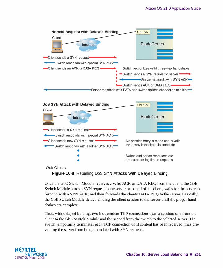
Alteon OS 21.0 Application Guide
Figure 10-8 Repelling DoS SYN Attacks With Delayed Binding
Once the GbE Switch Module receives a valid ACK or DATA REQ from the client, the GbE Switch Module sends a SYN request to the server on behalf of the client, waits for the server to respond with a SYN ACK, and then forwards the clients DATA REQ to the server. Basically, the GbE Switch Module delays binding the client session to the server until the proper hand-shakes are complete.
Thus, with delayed binding, two independent TCP connections span a session: one from the client to the GbE Switch Module and the second from the switch to the selected server. The switch temporarily terminates each TCP connection until content has been received, thus pre-venting the server from being inundated with SYN requests.
InternetInternet
InternetInternet BladeCenterBladeCenter
BladeCenterBladeCenter
GbESM
GbESM
Chapter 10: Server Load Balancing 20124R9742, March 2006
Alteon OS 21.0 Application Guide
NOTE – Delayed binding is automatically enabled when content intelligent switching features are used. However, if you are not parsing content, you must explicitly enable delayed binding if desired.
Configuring Delayed BindingTo configure your switch for delayed binding, use the following command:
NOTE – Enable delayed binding without configuring any HTTP SLB processing or persistent binding types.
To configure delayed binding for cache redirection, see “Delayed Binding for Cache Redirec-tion” on page 294.
Detecting SYN AttacksIn Alteon OS, SYN attack detection is enabled by default, whenever delayed binding is enabled. SYN attack detection:
Provides a way to track half open connections
Activates a trap notifying that the configured threshold is exceeded
Monitors DoS attacks and proactively signals alarm
Provides enhanced security
Improves visibility and protection for DoS attacks
The probability of a SYN attack is higher if excessive half-open sessions are being generated on the GbE Switch Module. Half-open sessions show an incomplete three-way handshake between the server and the client. You can view the total number of half-open sessions from the /stat/slb/layer7/maint menu.
To detect SYN attacks, the GbE Switch Module keeps track of the number of new half-open sessions for a set period of time. If the value exceeds the threshold, then a syslog message and an SNMP trap are generated.
You can change the default parameters for detecting SYN attacks in the /cfg/slb/adv/synatk menu. You can specify how frequently you want to check for SYN attacks, from 2 seconds to a minute and modify the default threshold representing the number of new half-open sessions per second.
>> # /cfg/slb/virt <virtual server number>/service <service type>/dbind
202 Chapter 10: Server Load Balancing24R9742, March 2006

Alteon OS 21.0 Application Guide
Session Initiation Protocol Server Load BalancingSession Initiation Protocol (SIP) is an application-level control (signaling) protocol for Internet multimedia conferencing, telephony, event notification, and instant messaging. The protocol initiates call setup, routing, authentication and other feature messages to end-points within an IP domain.
Session Initiation Protocol (SIP) is used to locate users (where the caller and called parties are located), determine user capability (what type of protocol TCP, UDP, and other capabilities the user can support), user availability, call setup (how to create the call), and call handling (how to keep the call up, and how to bring down the call).
This feature load balances SIP proxy servers such as Nortel MCS (Multimedia Communica-tions Server). Alteon OS 21.0 supports UDP-based SIP server load balancing only.
Session Initiation Protocol (SIP) load balancing is designed for Nortel MCS 1.0, but this feature can function with any SIP servers that use shared or clustered databases, such as CommuniGate Pro. All SIP servers must share signaling data (registration, invites, etc.).
SIP Processing on the SwitchSession Initiation Protocol (SIP) processing provides the capability to scan and hash calls based on a SIP Call-ID header to a SIP server. The Call-ID uniquely identifies a specific SIP session. Future messages from the same Call-ID is switched to the same SIP server. This involves stateful inspection of SIP messages.
Session Initiation Protocol (SIP) is a text based protocol with header lines preceding the con-tent. Like HTTP, the first header line has the method specification followed by other header lines that specify other parameters like Call-ID etc.
Chapter 10: Server Load Balancing 20324R9742, March 2006

Alteon OS 21.0 Application Guide
Configuring SIP Server Load Balancing Figure 10-9 illustrates an Nortel Application Switch performing UDP-based Session Initiation Protocol (SIP) server load balancing. In this example, three SIP proxy servers are configured in a Real Server Group 100. The application switch is configured for SIP service (port 5060) for virtual server 40.40.40.100.
Figure 10-9 Session Initiation Protocol Load Balancing
Follow this procedure to configure the topology illustrated in Figure 10-9 on page 204:
1. At the Nortel Application Switch, before you start configuring SIP load balancing:
Connect each SIP proxy server to the application switchConfigure the IP addresses on all devices connected to the application switchConfigure the IP interfaces on the application switchEnable Virtual Matrix Architecture (VMA)Enable Direct Access Mode (DAM)Disable proxy IP addressing
2. Enable server load balancing.
>> # /cfg/slb/on
BladeCenter
GbESM
7
5
6
Clients
Internet
SIP Proxy Servers
Router
A
C
B
IP 170.10.10.8
IP 210.210.210.10
IP 120.120.120.5
Real server 1IP 10.10.10.1
Real server 2IP 10.10.10.2
Real server 3IP 10.10.10.3
Virtual IP address: 40.40.40.100
204 Chapter 10: Server Load Balancing24R9742, March 2006

Alteon OS 21.0 Application Guide
3. Configure IP addresses for the SIP proxy servers.
4. Create a group to load balance the MCS servers.
5. Define the group metric for the server group.
Because SIP load balancing is done based on Call-ID, minmisses metric only is supported to ensure persistency.
6. Define the health check for the group.
Configure SIP PING request health check which is specifically developed for SIP-enabled servers.
7. Configure a virtual server for Layer 4 SIP load balancing.
8. Configure the SIP service 5060 for virtual server 1.
9. Enable SIP server load balancing.
>> # /cfg/slb/real 1/rip 10.10.10.1 (Define address for MCS 1)>> Real server 1# ena (Enable real server 1)>> # /cfg/slb/real 2/rip 10.10.10.2 (Define address for MCS 2)>> Real server 2# ena (Enable real server 2)>> # /cfg/slb/real 3/rip 10.10.10.3 (Define address for MCS 3)>> Real server 3# ena (Enable real server 3)
>> # /cfg/slb/group 100 (Define a group)>>Real Server Group 100# add 1 (Add real server 1)>>Real Server Group 100# add 2 (Add real server 2)>>Real Server Group 100# add 3 (Add real server 3)
>>Real Server Group 100# metric minmiss (Set the metric to minmisses)
>>Real Server Group 100# health sip (Set the health check to sip)
>> # /cfg/slb/virt 1 (Select virtual server 1)>>Virtual Server 1# vip 40.40.40.100 (Set IP address for the virtual server)>>Virtual Server 1# virt ena (Enable virtual server)
>> # /cfg/slb/virt 1/service 5060 (Add the SIP service for virt 1)
>>Virtual Server 1 sip Service # sip ena (Enable SIP for virtual server 1)
Chapter 10: Server Load Balancing 20524R9742, March 2006

Alteon OS 21.0 Application Guide
10. Enable DAM.
11. Enable UDP load balancing.
12. Increase the timeout for idle sessions.
SIP sessions are quite long and data may be flowing while the signalling path is idle. Because the switch resides in the signalling path, it is recommended to increase the Real server session timeout value to 30 minutes (default value is 10 minutes).
When the call terminates with a BYE command, the application switch releases the session entry immediately.
13. Enable server and client processing at the port level.
14. Apply and save your changes.
>>Virtual Server 1 sip Service # direct ena(Enable DAM)
>>Virtual Server 1 sip Service # udp ena (Enable UDP load balancing)
>> # /cfg/slb/real 1/tmout 30 (Increase Real 1 session timeout)>> # /cfg/slb/real 2/tmout 30 (Increase Real 2 session timeout)>> # /cfg/slb/real 3/tmout 30 (Increase Real 3 session timeout)
>> # /cfg/slb/port ext1 (Select the client port)>>SLB port EXT1# client ena (Enable client processing)>>SLB port EXT1# /cfg/slb/port int5 (Select the server port) >>SLB port INT5# server ena (Enable server processing)>>SLB port INT5# /cfg/slb/port int6 (Select the server port) >>SLB port INT6# server ena (Enable server processing)>>SLB port INT6# /cfg/slb/port int7 (Select the server port) >>SLB port INT7# server ena (Enable server processing)
>> SLB Port INT7# apply>> SLB Port INT7# save
206 Chapter 10: Server Load Balancing24R9742, March 2006

Alteon OS 21.0 Application Guide
Workload Manager SupportAlteon OS 21.0 supports the Server/Application State Protocol (SASP) used by the Enterprise Workload Management (WLM).
The Workload Manager feature is used to monitor server resources and provide additional input on load balancing decisions. The Workload Manager takes into account a server’s CPU, storage capacity, and network traffic in any final weighting decisions. The Workload Manager uses an implementation of the SASP protocol to perform this task.
The WLM software developed by IBM allows you to specify end-to-end performance goals for distributed requests. WLM runs on an entity responsible for reporting or managing a group of members. This entity is known as the Domain Manager (DM). DM recommends a weight for each application/server in the group. This weight recommendation is based on the business importance, topology and ability of the system to meet its business goals. This recommended weights helps the application switch make intelligent server load balancing decisions.
Alteon OS 21.0 also supports WLM in the redirect filter environment.
The SASP protocol enables the application switch to
receive traffic weight recommendations from DM
register members of the application switch with DM
enable GWM to propose new group members to the application switch
How the Application Switch works with the DMThe application switch initiates a TCP connection with the GWM for all the configured IP address and port numbers. After establishing the connection, the application switch registers various WLM-configured groups of real servers with the GWM.
In case of application load balancing, the representation of a member is the real servers’s IP address and the application’s port and protocol. When the members are registered, the GWM starts monitoring and computes the weight. The DM periodically sends the weights for all the registered groups.
When a real server is disabled/enabled operationally the switch sends a request to temporarily remove the server from the weight calculation.
Chapter 10: Server Load Balancing 20724R9742, March 2006

Alteon OS 21.0 Application Guide
Configuring WLM SupportBefore you start configuring for WLM support, make sure you have configured the following on the switch for all the groups and real servers participating in dynamic weights with Work-Load Managers (WLM):
switch name (/cfg/sys/ssnmp/name)
group name (/cfg/slb/group #/name)
real server names (/cfg/slb/real #/name)
You can configure up to 16 Work Load Managers (WLM).
1. Configure the IP address and the TCP port number to connect to the WLM.
2. Assign the WLM number to the server/application group.
If the WLM number is not specified, then this group is not registered with the WLM. As a result, dynamic weights are not used for this group.
3. Specify if WLM should use data or management port.
4. Apply and save the configuration.
>> Main# /cfg/slb/wlm 11>> Workload Manager 1# addr 10.10.10.10 (IP address of the WLM)>> Workload Manager 1# port 10 (TCP port to connect to the WLM)
>> Main# /cfg/slb/group 2>> Real Server Group 1# wlm 11>> Default gateway 1# apply
>> Main# /cfg/slb/mmgmt>> Management Port# wlm mgmt
>> Management Port# apply >> Management Port# save
208 Chapter 10: Server Load Balancing24R9742, March 2006
CHAPTER 11Global Server Load Balancing
This chapter provides information for configuring Global Server Load Balancing (GSLB) across multiple geographic sites. The following topics are covered:
“GSLB Overview” on page 210
“GSLB Enhancements” on page 213
“Configuring Basic GSLB” on page 217
“Configuring a Standalone GSLB Domain” on page 231
“Configuring GSLB with Rules” on page 235
“Configuring GSLB Network Preference” on page 239
“Configuring GSLB with Proxy IP for Non-HTTP Redirects” on page 242
“Using Border Gateway Protocol for GSLB” on page 246
“Verifying GSLB Operation” on page 247
DSSP version 1 vs. version 2Distributed Site Selection Protocol (DSSP) is a proprietary protocol that resides above TCP. It enables sending and receiving remote site updates. DSSP version 2 is used in Alteon OS 21.0, and supports server response time, CPU utilization, session availability, and session utilization in the remote site updates. (For more information on the site selection metrics, see “GSLB Metrics” on page 213.)
If you are using a GbE Switch Module for the first time starting with Alteon OS 21.0, then you should start any GSLB by first setting DSSP to version 2. The command to change to DSSP version 2 is /cfg/slb/gslb/version 2.
24R9742, March 2006209

Alteon OS 21.0 Application Guide
GSLB OverviewGSLB allows balancing server traffic load across multiple physical sites. The Alteon OS GSLB implementation takes into account an individual site’s health, response time, and geo-graphic location to smoothly integrate the resources of the dispersed server sites for complete global performance.
BenefitsGSLB meets the following demands for distributed network services:
High content availability is achieved through distributed content and distributed decision making. If one site becomes disabled, the others become aware of it and take up the load.There is no latency during client connection set up. Instant site hand-off decisions can be made by any distributed switch.The best performing sites receive a majority of traffic over a given period of time but are not overwhelmed.Switches at different sites regularly exchange information through the Distributed Site State Protocol (DSSP), and can trigger exchanges when any site’s health status changes. This ensures that each active site has valid state knowledge and statistics. DSSP v1.0 and DSSP v2.0 are supported.GSLB implementation takes geography as well as network topology into account.Creative control is given to the network administrator or Webmaster to build and control content by user, location, target application, and more.GSLB is easy to deploy, manage, and scale. Switch configuration is straightforward. There are no complex system topologies involving routers, protocols, and so forth.Flexible design options are provided.All IP protocols are supported.
24R9742, March 2006210 Chapter 11: Global Server Load Balancing
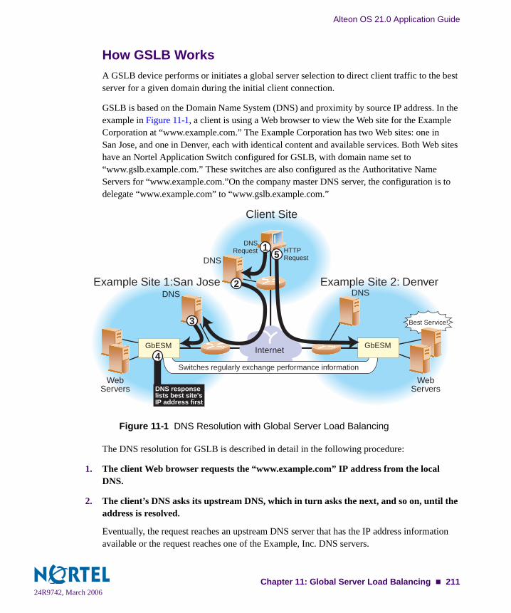
Alteon OS 21.0 Application Guide
How GSLB WorksA GSLB device performs or initiates a global server selection to direct client traffic to the best server for a given domain during the initial client connection.
GSLB is based on the Domain Name System (DNS) and proximity by source IP address. In the example in Figure 11-1, a client is using a Web browser to view the Web site for the Example Corporation at “www.example.com.” The Example Corporation has two Web sites: one in San Jose, and one in Denver, each with identical content and available services. Both Web sites have an Nortel Application Switch configured for GSLB, with domain name set to “www.gslb.example.com.” These switches are also configured as the Authoritative Name Servers for “www.example.com.”On the company master DNS server, the configuration is to delegate “www.example.com” to “www.gslb.example.com.”
Figure 11-1 DNS Resolution with Global Server Load Balancing
The DNS resolution for GSLB is described in detail in the following procedure:
1. The client Web browser requests the “www.example.com” IP address from the local DNS.
2. The client’s DNS asks its upstream DNS, which in turn asks the next, and so on, until the address is resolved.
Eventually, the request reaches an upstream DNS server that has the IP address information available or the request reaches one of the Example, Inc. DNS servers.
Internet
Switches regularly exchange performance information
Example Site 1:San Jose Example Site 2: Denver
Client Site
DNS
DNS
WebServers
WebServers
DNS
Best Service!
GbESMGbESM
3
2
15
4
DNS responselists best site'sIP address first
DNSRequest HTTP
Request
24R9742, March 2006Chapter 11: Global Server Load Balancing 211
Alteon OS 21.0 Application Guide
3. The Example Inc.’s San Jose DNS tells the local DNS to query the Nortel Application Switch with GSLB software as the authoritative name server for “www.example.com.”
4. The San Jose switch responds to the DNS request, listing the IP address with the current best service.
Each switch with GSLB software is capable of responding to the client’s name resolution request. Since each switch regularly checks and communicates health and performance infor-mation with its peers, either switch can determine which site(s) are best able to serve the cli-ent’s Web access needs. It can respond with a list of IP addresses for the Example Inc.’s distributed sites, which are prioritized by performance, geography, and other criteria.
In this case, the San Jose switch knows that Example Inc. Denver currently provides better ser-vice, and lists Example Inc. Denver’s virtual server IP address first when responding to the DNS request.
5. The client connects to Example Inc. Denver for the best service.
The client’s Web browser will use the IP address information obtained from the DNS request to open a connection to the best available site. The IP addresses represent virtual servers at any site, which are locally load balanced according to regular SLB configuration.
If the site serving the client HTTP content suddenly experiences a failure (no healthy real serv-ers) or becomes overloaded with traffic (all real servers reach their maximum connection limit), the switch issues an HTTP Redirect and transparently causes the client to connect to another peer site.
The end result is that the client gets quick, reliable service with no latency and no special cli-ent-side configuration.
24R9742, March 2006212 Chapter 11: Global Server Load Balancing

Alteon OS 21.0 Application Guide
GSLB EnhancementsGSLB has been enhanced with the following new features in Alteon OS 21.0.
Distributed Site Selection Protocol version 2—DSSP version 2 can be configured to send updates over TCP ports besides port 80, and can handle additional parameter exchanges as described in “DSSP version 1 vs. version 2” on page 209. DSSP is a propri-etary protocol residing above TCP.
Network Preference Table—supports multiple servers. The network preference table can be used for HTTP redirect GSLB.
Rule and metric preference per virtual server/domain—each virtual server/domain can use different rules, listing different metric preferences, supporting load balancing vs multi-ple site high availability.
New static and load site selection metrics for rule-based processing—several new met-rics have been added for rule-based processing, as described in “GSLB Metrics” on page 213.
Prioritization and weighting of GSLB metrics—selection of GSLB metrics can be pri-oritized by configuring a GSLB rule, as described in “Configuring GSLB with Rules” on page 235.
GSLB MetricsThis section describes all GSLB metrics. The (New) items are newly introduced as of Alteon OS 21.0. All metrics can be prioritized for selection order, and can be weighted on per site basis.
For details on the configuration parameters of GSLB metrics, see the /cfg/slb/gslb/rule menu and the command descriptions in the Alteon OS 21.0 Command Reference.
Session utilization capacity threshold (New)—This metric causes the GSLB-enabled switch to not select the server when the session utilization of the server goes above the threshold. The session utilization is the percentage of sessions used over total sessions that results in normalized sessions between servers. When the server is not available, the ses-sion utilization is 100%. This is a threshold metric and it overwrites all other metrics. This metric requires remote site updates.
24R9742, March 2006Chapter 11: Global Server Load Balancing 213

Alteon OS 21.0 Application Guide
CPU utilization capacity threshold (new)—This metric causes the GSLB-enabled switch to not select the server when the CPU utilization of the site with the server goes above the threshold. CPU utilization is the highest CPU utilization for periods of up to 64 seconds among SPs. This is a threshold metric and overwrites all other metrics.This metric requires remote site updates.
Session available capacity threshold—This metric does not select the server when the number of available sessions on the server falls below the threshold. When the server is not available, the session available is 0. This is a threshold metric and it overwrites all other metrics. This metric requires remote site updates.
Geographical preference—This metric causes the GSLB-enabled switch to select the server based on the same IANA region of the source IP address and the server IP address. This metric does not require remote site updates. The command, /info/slb/gslb/geo can be used to obtain a list of the IP address ranges that are mapped to each region. The regions are as follows:
North AmericaSouth AmericaEuropeCaribbeanPacific RimSub-SaharaJapan
Network preference (client proximity)—This metric selects the server based on the pre-ferred network of the source IP address. This metric does not require remote site updates.
Weighted least connections (new)—This metric selects the server based on which server has the lowest session utilization. Session utilization is the percentage of sessions used over total sessions, which results in normalized sessions between servers. A server whose session utilization is 100% is considered unavailable. This metric requires remote site updates.
Weighted response time—This metric selects the server based on the lowest response time in milliseconds from an SLB health check of the servers. This metric requires SLB health checks and remote site updates.
Weighted round robin (new)—This metric selects the server based on round robin of the servers.
Weighted random (new)—This metric selects the server based on uniform random distri-bution of the servers.
24R9742, March 2006214 Chapter 11: Global Server Load Balancing

Alteon OS 21.0 Application Guide
Availability (new)—This metric selects the same server while the server is still available. If the same server is not available, this metric selects the next server based on a ranking of the local virtual server and remote real server in a list from the highest (48) to the lowest (1) ranking. Multiple servers can have the same priority. This metric allows servers to be grouped based on priorities, or into primary and secondary groups. This metric requires SLB health checks and remote site updates.
Quality of service (new)—This metric selects the server based on combination of the low-est session utilization and the lowest response time of the SLB health check of the servers. This metric requires SLB health checks and remote site updates.
Minmisses (new) —This metric selects the same server based on the hash of source IP address and domain name. The hash calculation uses all the servers that are configured for the domain irrespective of the state of the server. When the server selected is not available, minmisses selects the next available server.
Hashing (new)—This metric selects the same server based on the hash of source IP address and domain name. The hash calculation uses only the servers that are available for the domain. The server selected may be affected when a server become available or not available since the hash calculation uses only the servers that are available.
DNS local—This metric selects the local virtual server only when the local virtual server is available. This metric applies to DNS-based GSLB only.
DNS always—This metric selects the local virtual server even though the local virtual server is not available. This metric applies to DNS-based GSLB only.
Remote—This metric selects the remote real servers only.
24R9742, March 2006Chapter 11: Global Server Load Balancing 215

Alteon OS 21.0 Application Guide
Metric preferencesThis metric allows the GSLB selection to use multiple metrics from a metric preference list. The GSLB selection starts with the first metric in the list. The GSLB selection goes to the next metric when no server is selected, or more than the required servers is selected. The GSLB selection stops when the metric results at least one and no more than the required servers, or after the last metric in the list is reached. For DNS direct-based GSLB, the DNS response can be configured to return up to 10 required servers. For HTTP redirects based GSLB, the required server is one.
The following metrics can be selected from the metric preference list.
Geographical preferenceNetwork preferenceLeast connectionsResponse timeRound robinRandomAvailabilityQuality of serviceMinmissesHashingDNS localDNS alwaysRemote
Rules A rule allows the GSLB selection to use a different GSLB site selection metric preference list, and rules can be set based on the time of day. Each domain has one or more rules. Each rule has a metric preference list. The GSLB selection selects the first rule that matches for the domain and starts with the first metric in the metric preference list of the rule. For more information, see “Configuring GSLB with Rules” on page 235.
24R9742, March 2006216 Chapter 11: Global Server Load Balancing
Alteon OS 21.0 Application Guide
Configuring Basic GSLBConfiguring GSLB is simply an extension of the configuration procedure for SLB. The process is summarized as follows:
Use the administrator login to connect to the switch you want to configure.
Activate the GSLB software key. See the Alteon OS Command Reference for details.
Configure the switch at each site with basic attributes.
Configure the switch IP interface.
Configure the default gateways.
Configure the switch at each site to act as the DNS server for each service that is hosted on its virtual servers. Also, configure the master DNS server to recognize the switch as the authoritative DNS server for the hosted services.
Configure the switch at each site for local SLB.
Define each local real server.
Group local real servers into real server groups.
Define the local virtual server with its IP address, services, and real server groups.
Define the switch port states.
Enable SLB.
Finally, configure each switch so that it recognizes its remote peers.
Configure a remote real server entry on each switch for each remote service. This is the virtual server IP address that is configured on the remote peer.
Add the remote real server entry to an appropriate real server group.
Enable GSLB.
24R9742, March 2006Chapter 11: Global Server Load Balancing 217

Alteon OS 21.0 Application Guide
Basic GSLB RequirementsThe following is required prior to configuration:
You must be connected to the switch Command Line Interface (CLI) as the administrator.The optional GSLB software key must be activatedServer Load Balancing must be enabled.
Example GSLB TopologyConsider the following example network:
Figure 11-2 GSLB Topology Example 1
In the following examples, many of the options are left to their default values. See “Additional Server Load Balancing Options” on page 182 for more options.
NOTE – For details about any of the processes or menu commands described in this example, see the Alteon OS Command Reference.
San Jose–Site 1 Denver–Site 2200.200.200.X Network 174.14.70.X Network
Web Servers:200.2.2.10200.2.2.20VLAN 201
Web Servers:174.40.7.11174.40.7.21 VLAN 202
10
20 2111
IP Interface 101200.200.200.1
VIP: 200.200.200.100 VLAN 101
IP Interface 201200.2.2.201 VLAN 201
IP Interface 102:174.14.70.2
VIP: 174.14.70.200 VLAN 102
IP Interface 202174.40.7.202VLAN 202
Internet
GSLB 1 GSLB 2
DNS Server
Default GW200.200.200.101
Default GW174.14.70.101
DNS Server
GbESMGbESM
24R9742, March 2006218 Chapter 11: Global Server Load Balancing

Alteon OS 21.0 Application Guide
Task 1: Configure the Basics at the San Jose Site
1. If using the Browser-Based Interface (BBI) for managing the San Jose switch, change its service port.
By default, GSLB listens on service port 80 for HTTP redirection. By default, the Alteon OS Browser-Based Interface (BBI) also uses port 80. Both services cannot use the same port. If the BBI is enabled (see the /cfg/sys/access/http command in the Alteon OS Command Refer-ence), configure it to use a different port.
For example, enter the following command to change the BBI port to 8080:
2. Configure a VLAN for the Internet traffic.
3. Configure another VLAN for local server traffic, and add server ports to this VLAN.
>> # /cfg/sys/wport 8080 (Set service port 8080 for BBI)
>> # /cfg/l2/vlan 101/name internet (VLAN 101 for Internet)>> VLAN 101# add ext2/ena (Add port EXT2 to VLAN 101)Port EXT2 is an UNTAGGED port and its current PVID is 1.Confirm changing PVID from 1 to 101 [y/n]: yCurrent ports for VLAN 101: emptyPending new ports for VLAN 101: EXT2Current status: disabledNew status: enabled
>> # /cfg/l2/vlan 201/name servers (VLAN 201 for local servers) >> VLAN 201# add int4/ena (Add port INT4 to VLAN 201)Port INT4 is an UNTAGGED port and its current PVID is 1.Confirm changing PVID from 1 to 201 [y/n]: yCurrent ports for VLAN 201: emptyPending new ports for VLAN 201: INT4Current status: disabledNew status: enabled>> VLAN 201# add int3/ena (Add port INT3 to VLAN 201)Port INT3 is an UNTAGGED port and its current PVID is 1.Confirm changing PVID from 1 to 201 [y/n]: yCurrent ports for VLAN 201: emptyPending new ports for VLAN 201: INT3 INT4
24R9742, March 2006Chapter 11: Global Server Load Balancing 219
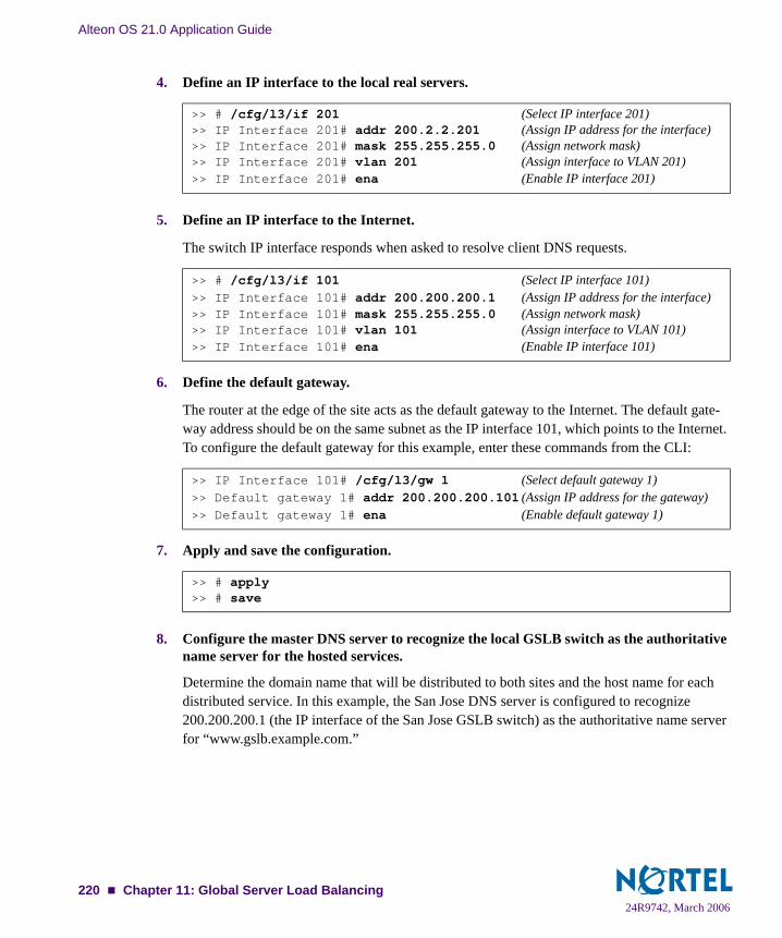
Alteon OS 21.0 Application Guide
4. Define an IP interface to the local real servers.
5. Define an IP interface to the Internet.
The switch IP interface responds when asked to resolve client DNS requests.
6. Define the default gateway.
The router at the edge of the site acts as the default gateway to the Internet. The default gate-way address should be on the same subnet as the IP interface 101, which points to the Internet. To configure the default gateway for this example, enter these commands from the CLI:
7. Apply and save the configuration.
8. Configure the master DNS server to recognize the local GSLB switch as the authoritative name server for the hosted services.
Determine the domain name that will be distributed to both sites and the host name for each distributed service. In this example, the San Jose DNS server is configured to recognize 200.200.200.1 (the IP interface of the San Jose GSLB switch) as the authoritative name server for “www.gslb.example.com.”
>> # /cfg/l3/if 201 (Select IP interface 201)>> IP Interface 201# addr 200.2.2.201 (Assign IP address for the interface)>> IP Interface 201# mask 255.255.255.0 (Assign network mask)>> IP Interface 201# vlan 201 (Assign interface to VLAN 201)>> IP Interface 201# ena (Enable IP interface 201)
>> # /cfg/l3/if 101 (Select IP interface 101)>> IP Interface 101# addr 200.200.200.1 (Assign IP address for the interface)>> IP Interface 101# mask 255.255.255.0 (Assign network mask)>> IP Interface 101# vlan 101 (Assign interface to VLAN 101)>> IP Interface 101# ena (Enable IP interface 101)
>> IP Interface 101# /cfg/l3/gw 1 (Select default gateway 1)>> Default gateway 1# addr 200.200.200.101 (Assign IP address for the gateway)>> Default gateway 1# ena (Enable default gateway 1)
>> # apply>> # save
24R9742, March 2006220 Chapter 11: Global Server Load Balancing

Alteon OS 21.0 Application Guide
Task 2: Configure the San Jose Switch for Standard SLB
1. Assign an IP address to each of the real servers in the local San Jose server pool.
The real servers in any real server group must have an IP route to the switch that will perform the SLB functions. This is most easily accomplished by placing the switches and servers on the same IP subnet, although advanced routing techniques can be used as long as they do not vio-late the topology rules outlined in “Network Topology Requirements” on page 176.
For this example, the host real servers have IP addresses on the same IP subnet:
2. Define each local real server.
For each local real server, you must assign a real server number, specify its actual IP address, and enable the real server. For example:
3. On the San Jose switch, define a real server group.
Combine the real servers into one service group and set the necessary health checking parame-ters. In this example, HTTP health checking is used to ensure that Web content is being served. If the index.html file is not accessible on a real server during health checks, the real server will be marked as down.
Table 11-1 GSLB Example: San Jose Real Server IP Addresses
Real Server IP address
Server 10 200.2.2.10
Server 20 200.2.2.20
>> Default gateway 1# /cfg/slb/real 10 (Configure Real Server 10)>> Real server 10# rip 200.2.2.10 (Assign IP address to server 10)>> Real server 10# ena (Enable real server 10)>> Real server 10# /cfg/slb/real 20 (Configure Real Server 20)>> Real server 20# rip 200.2.2.20 (Assign IP address to server 20)>> Real server 20# ena (Enable real server 20)
>> Real server 2# /cfg/slb/group 1 (Select real server group 1)>> Real server group 1# add 10 (Add real server 10 to group 1)>> Real server group 1# add 20 (Add real server 20 to group 1)>> Real server group 1# health http (Use HTTP for health checks)>> Real server group 1# content index.html (Set URL content for health checks)
24R9742, March 2006Chapter 11: Global Server Load Balancing 221
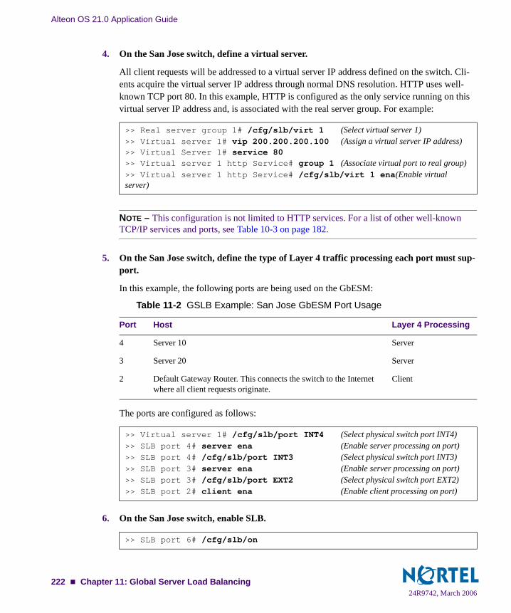
Alteon OS 21.0 Application Guide
4. On the San Jose switch, define a virtual server.
All client requests will be addressed to a virtual server IP address defined on the switch. Cli-ents acquire the virtual server IP address through normal DNS resolution. HTTP uses well-known TCP port 80. In this example, HTTP is configured as the only service running on this virtual server IP address and, is associated with the real server group. For example:
NOTE – This configuration is not limited to HTTP services. For a list of other well-known TCP/IP services and ports, see Table 10-3 on page 182.
5. On the San Jose switch, define the type of Layer 4 traffic processing each port must sup-port.
In this example, the following ports are being used on the GbESM:
The ports are configured as follows:
6. On the San Jose switch, enable SLB.
>> Real server group 1# /cfg/slb/virt 1 (Select virtual server 1)>> Virtual server 1# vip 200.200.200.100 (Assign a virtual server IP address)>> Virtual Server 1# service 80>> Virtual server 1 http Service# group 1 (Associate virtual port to real group)>> Virtual server 1 http Service# /cfg/slb/virt 1 ena(Enable virtual server)
Table 11-2 GSLB Example: San Jose GbESM Port Usage
Port Host Layer 4 Processing
4 Server 10 Server
3 Server 20 Server
2 Default Gateway Router. This connects the switch to the Internet where all client requests originate.
Client
>> Virtual server 1# /cfg/slb/port INT4 (Select physical switch port INT4)>> SLB port 4# server ena (Enable server processing on port)>> SLB port 4# /cfg/slb/port INT3 (Select physical switch port INT3)>> SLB port 3# server ena (Enable server processing on port)>> SLB port 3# /cfg/slb/port EXT2 (Select physical switch port EXT2)>> SLB port 2# client ena (Enable client processing on port)
>> SLB port 6# /cfg/slb/on
24R9742, March 2006222 Chapter 11: Global Server Load Balancing
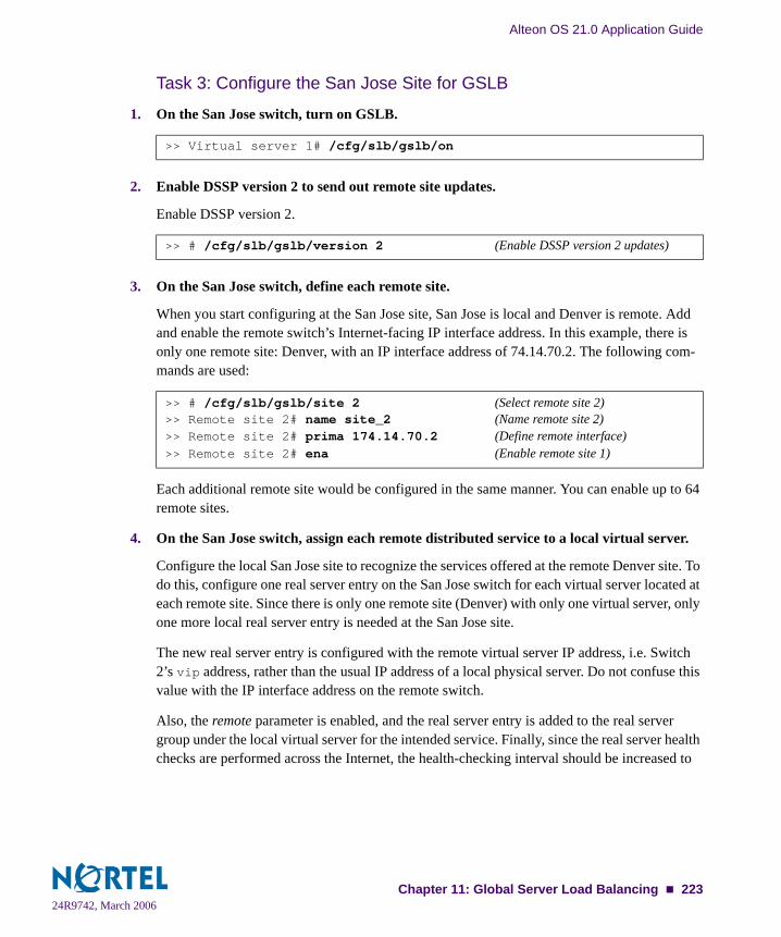
Alteon OS 21.0 Application Guide
Task 3: Configure the San Jose Site for GSLB
1. On the San Jose switch, turn on GSLB.
2. Enable DSSP version 2 to send out remote site updates.
Enable DSSP version 2.
3. On the San Jose switch, define each remote site.
When you start configuring at the San Jose site, San Jose is local and Denver is remote. Add and enable the remote switch’s Internet-facing IP interface address. In this example, there is only one remote site: Denver, with an IP interface address of 74.14.70.2. The following com-mands are used:
Each additional remote site would be configured in the same manner. You can enable up to 64 remote sites.
4. On the San Jose switch, assign each remote distributed service to a local virtual server.
Configure the local San Jose site to recognize the services offered at the remote Denver site. To do this, configure one real server entry on the San Jose switch for each virtual server located at each remote site. Since there is only one remote site (Denver) with only one virtual server, only one more local real server entry is needed at the San Jose site.
The new real server entry is configured with the remote virtual server IP address, i.e. Switch 2’s vip address, rather than the usual IP address of a local physical server. Do not confuse this value with the IP interface address on the remote switch.
Also, the remote parameter is enabled, and the real server entry is added to the real server group under the local virtual server for the intended service. Finally, since the real server health checks are performed across the Internet, the health-checking interval should be increased to
>> Virtual server 1# /cfg/slb/gslb/on
>> # /cfg/slb/gslb/version 2 (Enable DSSP version 2 updates)
>> # /cfg/slb/gslb/site 2 (Select remote site 2)>> Remote site 2# name site_2 (Name remote site 2)>> Remote site 2# prima 174.14.70.2 (Define remote interface)>> Remote site 2# ena (Enable remote site 1)
24R9742, March 2006Chapter 11: Global Server Load Balancing 223

Alteon OS 21.0 Application Guide
30 or 60 seconds to avoid generating excess traffic. The health check interval should also depend on the number of remote sites. The more remote sites you have, the larger the time interval should be. For example:
NOTE – Take care to note where each configured value originates, or this step can result in improper configuration.
5. On the San Jose switch, define the domain name and host name for each service hosted on each virtual server.
In this example, the domain name for the Example Inc. is “gslb.example.com,” and the host name for the only service (HTTP) is “www.” These values are configured as follows:
To define other services (such as FTP), make additional hostname entries.
6. Apply and verify the configuration.
Examine the resulting information. If any settings are incorrect, make and apply any appropri-ate changes, and then check again.
7. Save your new configuration changes.
>> # /cfg/slb/real 2 (Create an entry for real server 2)>> Real server 2# rip 174.14.70.200 (Set remote virtual server IP address)>> Real server 3# remote enable (Define the real server as remote)>> Real server 3# inter 30 (Set a higher health check interval)>> Real server 3# ena (Enable the real server entry)>> Real server 3# /cfg/slb/group 1 (Select appropriate real server group)>> Real server group 1# add 2 (Add real server 2 to the group 1)
>> Real server group 1# /cfg/slb/virt 1 (Select virtual server 1)>> Virtual server 1# dname gslb.example.com (Define domain name)>> Virtual server 1# service 80/hname www (Define HTTP host name)
>> Global SLB# apply (Make your changes active)>> Global SLB# cur (View current GSLB settings)>> Global SLB# /cfg/slb/cur (View current SLB settings)
>> Layer 4# save (Save for restore after reboot)
24R9742, March 2006224 Chapter 11: Global Server Load Balancing
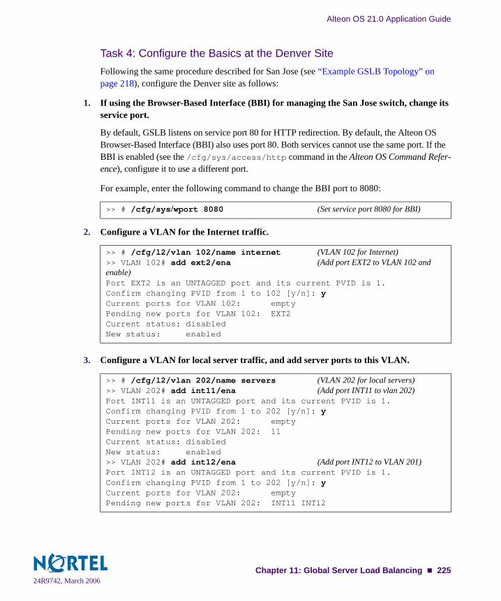
Alteon OS 21.0 Application Guide
Task 4: Configure the Basics at the Denver SiteFollowing the same procedure described for San Jose (see “Example GSLB Topology” on page 218), configure the Denver site as follows:
1. If using the Browser-Based Interface (BBI) for managing the San Jose switch, change its service port.
By default, GSLB listens on service port 80 for HTTP redirection. By default, the Alteon OS Browser-Based Interface (BBI) also uses port 80. Both services cannot use the same port. If the BBI is enabled (see the /cfg/sys/access/http command in the Alteon OS Command Refer-ence), configure it to use a different port.
For example, enter the following command to change the BBI port to 8080:
2. Configure a VLAN for the Internet traffic.
3. Configure a VLAN for local server traffic, and add server ports to this VLAN.
>> # /cfg/sys/wport 8080 (Set service port 8080 for BBI)
>> # /cfg/l2/vlan 102/name internet (VLAN 102 for Internet)>> VLAN 102# add ext2/ena (Add port EXT2 to VLAN 102 and enable)Port EXT2 is an UNTAGGED port and its current PVID is 1.Confirm changing PVID from 1 to 102 [y/n]: yCurrent ports for VLAN 102: emptyPending new ports for VLAN 102: EXT2Current status: disabledNew status: enabled
>> # /cfg/l2/vlan 202/name servers (VLAN 202 for local servers) >> VLAN 202# add int11/ena (Add port INT11 to vlan 202)Port INT11 is an UNTAGGED port and its current PVID is 1.Confirm changing PVID from 1 to 202 [y/n]: yCurrent ports for VLAN 202: emptyPending new ports for VLAN 202: 11Current status: disabledNew status: enabled>> VLAN 202# add int12/ena (Add port INT12 to VLAN 201)Port INT12 is an UNTAGGED port and its current PVID is 1.Confirm changing PVID from 1 to 202 [y/n]: yCurrent ports for VLAN 202: emptyPending new ports for VLAN 202: INT11 INT12
24R9742, March 2006Chapter 11: Global Server Load Balancing 225

Alteon OS 21.0 Application Guide
4. Define an IP interface to the local real servers.
5. Define an IP interface to the Internet.
6. Define the default gateway.
7. Apply and save the configuration.
8. Configure the local DNS server to recognize the local GSLB switch as the authoritative name server for the hosted services.
Determine the domain name that will be distributed to both sites and the host name for each distributed service. In this example, the Denver DNS server is configured to recognize 174.14.70.2 (the IP interface of the Denver GSLB switch, configured with the domain name “www.gslb.example.com”) as the authoritative name server for “www.example.com.”
>> # /cfg/l3/if 202 (Select IP interface 202)>> IP Interface 202# addr 174.40.7.202 (Assign IP address for the interface)>> IP Interface 202# mask 255.255.255.0 (Assign network mask)>> IP Interface 202# vlan 202 (Assign interface to VLAN 202)>> IP Interface 202# ena (Enable IP interface 202)
>> # /cfg/l3/if 102 (Select IP interface 102)>> IP Interface 102# addr 174.14.70.2 (Assign IP address for the interface)>> IP Interface 102# mask 255.255.255.0 (Assign network mask)>> IP Interface 102# vlan 102 (Assign interface to VLAN 102)>> IP Interface 102# ena (Enable IP interface 102)
>> IP Interface 102# /cfg/l3/gw 1 (Select default gateway 1)>> Default gateway 1# addr 174.14.70.101 (Assign IP address for the gateway)>> Default gateway 1# ena (Enable default gateway 1)
>> # apply>> # save
24R9742, March 2006226 Chapter 11: Global Server Load Balancing

Alteon OS 21.0 Application Guide
Task 5: Configure the Denver Switch for Standard SLB
1. Assign an IP address to each of the real servers in the local Denver server pool.
2. On the Denver switch, define each local real server.
3. On the Denver switch, define a real server group.
4. On the Denver switch, define a virtual server.
Table 11-3 Denver Real Server IP Addresses
Real Server IP address
Server 11 174.14.7.11
Server 21 174.14.7.21
>> Default gateway 1# /cfg/slb/real 11 (Server C is real server 1)>> Real server 11# rip 174.14.7.11 (Assign IP address for Server 11)>> Real server 11# ena (Enable real server 11)>> Real server 11# /cfg/slb/real 21 (Server D is real server 21)>> Real server 21# rip 174.14.7.21 (Assign IP address for Server 21)>> Real server 21# ena (Enable real server 21)
>> Real server 2# /cfg/slb/group 1 (Select real server group 1)>> Real server group 1# add 11 (Add real server 11 to group 1)>> Real server group 1# add 21 (Add real server 21 to group 1)>> Real server group 1# health http (Use HTTP for health checks)>> Real server group 1# content index.html (Set URL content for health checks)
>> Real server group 1# /cfg/slb/virt 1 (Select virtual server 1)>> Virtual server 1# vip 174.14.70.200 (Assign IP address)>> Virtual server 1# service http (Select the HTTP service menu)>> Virtual server 1 http service# group 1 (Associate virtual port to real group)>> Virtual server 1 http service# /cfg/slb/virt 1/ena(Enable the virtual server)
24R9742, March 2006Chapter 11: Global Server Load Balancing 227
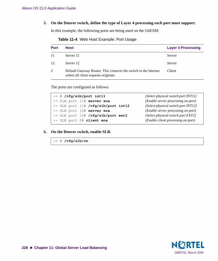
Alteon OS 21.0 Application Guide
5. On the Denver switch, define the type of Layer 4 processing each port must support.
In this example, the following ports are being used on the GbESM:
The ports are configured as follows:
6. On the Denver switch, enable SLB.
Table 11-4 Web Host Example: Port Usage
Port Host Layer 4 Processing
11 Server 11 Server
12 Server 12 Server
2 Default Gateway Router. This connects the switch to the Internet where all client requests originate.
Client
>> # /cfg/slb/port int11 (Select physical switch port INT11)>> SLB port 11# server ena (Enable server processing on port)>> SLB port 11# /cfg/slb/port int12 (Select physical switch port INT12)>> SLB port 12# server ena (Enable server processing on port)>> SLB port 12# /cfg/slb/port ext2 (Select physical switch port EXT2)>> SLB port 2# client ena (Enable client processing on port)
>> # /cfg/slb/on
24R9742, March 2006228 Chapter 11: Global Server Load Balancing

Alteon OS 21.0 Application Guide
Task 6: Configure the Denver Site for GSLBFollowing the same procedure described for San Jose (see “Task 3: Configure the San Jose Site for GSLB” on page 223), configure the Denver site as follows:
1. On the Denver switch, turn on GSLB.
2. Enable DSSP version 2 to send out remote site updates.
Enable DSSP version 2.
3. On the Denver switch, define each remote site.
When you start configuring at the Denver site, Denver is local and San Jose is remote. Add and enable the remote switch’s IP address interface. In this example, there is only one remote site: San Jose, with an IP interface address of 200.200.200.1. The following commands are used:
Each additional remote site would be configured in the same manner. You can enable up to 64 remote sites.
4. On the Denver switch, assign each remote distributed service to a local virtual server.
In this step, the local Denver site is configured to recognize the services offered at the remote San Jose site. As before, configure one real server entry on the Denver switch for each virtual server located at each remote site. Since there is only one remote site (San Jose) with only one virtual server, only one more local real server entry is needed at the Denver site.
The new real server entry is configured with the IP address of the remote virtual server, rather than the usual IP address of a local physical server. Do not confuse this value with the IP inter-face address on the remote switch.
Also, the remote parameter is enabled, and the real server entry is added to the real server group under the local virtual server for the intended service. Finally, since the real server health checks are headed across the Internet, the health-checking interval should be increased to 30 or 60 seconds to avoid generating excess traffic. The more remote sites you have, the larger the time interval should be.
>> Virtual server 1# /cfg/slb/gslb/on
>> # /cfg/slb/gslb/version 2 (Enable DSSP version 2 updates)
>> # /cfg/slb/gslb/site 1 (Select remote site 1)>> Remote site 1# prima 200.200.200.1 (Define remote IP interface address)>> Remote site 1# ena (Enable remote site 1)
24R9742, March 2006Chapter 11: Global Server Load Balancing 229
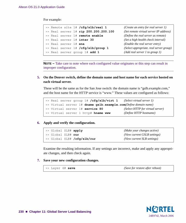
Alteon OS 21.0 Application Guide
For example:
NOTE – Take care to note where each configured value originates or this step can result in improper configuration.
5. On the Denver switch, define the domain name and host name for each service hosted on each virtual server.
These will be the same as for the San Jose switch: the domain name is “gslb.example.com,” and the host name for the HTTP service is “www.” These values are configured as follows:
6. Apply and verify the configuration.
Examine the resulting information. If any settings are incorrect, make and apply any appropri-ate changes, and then check again.
7. Save your new configuration changes.
>> Remote site 1# /cfg/slb/real 1 (Create an entry for real server 1)>> Real server 1# rip 200.200.200.100 (Set remote virtual server IP address)>> Real server 1# remote enable (Define the real server as remote)>> Real server 1# inter 30 (Set a high health check interval)>> Real server 1# ena (Enable the real server entry)>> Real server 1# /cfg/slb/group 1 (Select appropriate. real server group)>> Real server group 1# add 1 (Add real server 1 to group 1)
>> Real server group 1# /cfg/slb/virt 1 (Select virtual server 1)>> Virtual server 1# dname gslb.example.com(Define domain name)>> Virtual server 1# service 80 (Select HTTP for virtual server)>> Virtual server 1 http# hname www (Define HTTP hostname)
>> Global SLB# apply (Make your changes active)>> Global SLB# cur (View current GSLB settings)>> Global SLB# /cfg/slb/cur (View current SLB settings)
>> Layer 4# save (Save for restore after reboot)
24R9742, March 2006230 Chapter 11: Global Server Load Balancing

Alteon OS 21.0 Application Guide
Configuring a Standalone GSLB DomainAn GbE Switch Module can serve as a standalone GSLB device, which means that it can per-form GSLB health checking and site selection to other sites, without supporting SLB to local real servers.
The remote sites can be other sites configured with an GbE Switch Module running GSLB, an GbE Switch Module running only SLB, or even a site that uses another vendor’s load balanc-ers.
A GbE Switch Module running GSLB can operate in standalone mode as long as it uses site selection metrics that do not require remote site updates.
GSLB Topology with a Standalone GSLB Site
Figure 11-3 GSLB Topology Example 2—with Standalone GSLB
San Jose– SLB Site 1 Denver– SLB Site 2200.200.200.X Network 174.14.70.X Network
Web Servers:200.2.2.10200.2.2.20VLAN 201
Web Servers:174.40.7.11174.40.7.21 VLAN 202
10
20 2111
IP Interface 101200.200.200.1
VIP: 200.200.200.100 VLAN 101
IP Interface 201200.2.2.201 VLAN 201
IP Interface 102:174.14.70.2
VIP: 174.14.70.200 VLAN 102
IP Interface 202174.40.7.202VLAN 202
SLB 1 SLB 2
Internet
DNS Server
Default GW200.200.200.101
Default GW174.14.70.101
DNS Server
Tokyo– GSLB43.10.10.X Network
IP Interface43.10.10.3
VLAN 103
Standalone GSLB
Default GW43.10.10.103
DNS Server
GbESM
GbESM GbESM
24R9742, March 2006Chapter 11: Global Server Load Balancing 231
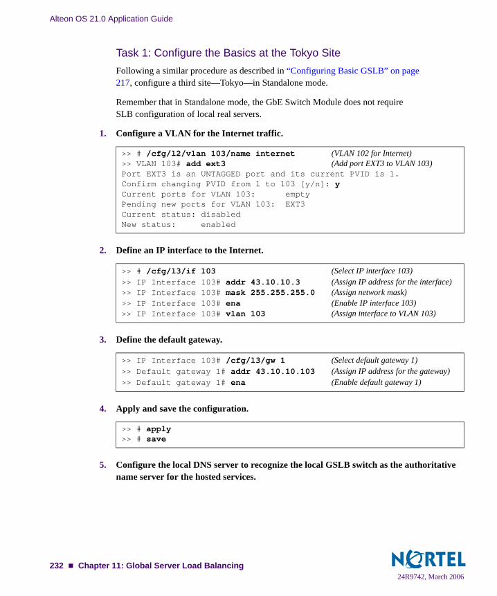
Alteon OS 21.0 Application Guide
Task 1: Configure the Basics at the Tokyo Site Following a similar procedure as described in “Configuring Basic GSLB” on page 217, configure a third site—Tokyo—in Standalone mode.
Remember that in Standalone mode, the GbE Switch Module does not require SLB configuration of local real servers.
1. Configure a VLAN for the Internet traffic.
2. Define an IP interface to the Internet.
3. Define the default gateway.
4. Apply and save the configuration.
5. Configure the local DNS server to recognize the local GSLB switch as the authoritative name server for the hosted services.
>> # /cfg/l2/vlan 103/name internet (VLAN 102 for Internet)>> VLAN 103# add ext3 (Add port EXT3 to VLAN 103)Port EXT3 is an UNTAGGED port and its current PVID is 1.Confirm changing PVID from 1 to 103 [y/n]: yCurrent ports for VLAN 103: emptyPending new ports for VLAN 103: EXT3Current status: disabledNew status: enabled
>> # /cfg/l3/if 103 (Select IP interface 103)>> IP Interface 103# addr 43.10.10.3 (Assign IP address for the interface)>> IP Interface 103# mask 255.255.255.0 (Assign network mask)>> IP Interface 103# ena (Enable IP interface 103)>> IP Interface 103# vlan 103 (Assign interface to VLAN 103)
>> IP Interface 103# /cfg/l3/gw 1 (Select default gateway 1)>> Default gateway 1# addr 43.10.10.103 (Assign IP address for the gateway)>> Default gateway 1# ena (Enable default gateway 1)
>> # apply>> # save
24R9742, March 2006232 Chapter 11: Global Server Load Balancing

Alteon OS 21.0 Application Guide
Determine the domain name that will be distributed to both sites and the host name for each distributed service. In this example, the Tokyo DNS server is configured to recognize 43.10.10.3 (the IP interface of the Tokyo GSLB switch) as the authoritative name server for “www.gslb.example.com.”
Task 2: Configure the Tokyo Site for GSLBFollowing the similar procedure described for San Jose (see “Task 3: Configure the San Jose Site for GSLB” on page 223), configure the Tokyo site as follows:
1. On the Tokyo switch, turn on SLB and GSLB.
2. On the Tokyo switch, assign each remote distributed service to a local virtual server.
In this step, the local site, Tokyo, is configured to recognize the services offered at the remote San Jose and Denver sites. As before, configure one real server entry on the Tokyo switch for each virtual server located at each remote site.
The new real server entry is configured with the IP address of the remote virtual server, rather than the usual IP address of a local physical server. Do not confuse this value with the IP interface address on the remote switch.
NOTE – Take care to note where each configured value originates, or this step can result in improper configuration.
>> # /cfg/slb (Select the SLB Menu)>> SLB# on (Activate SLB for the switch)>> # /cfg/slb/gslb (Select the GSLB Menu)>> Global SLB# on (Activate GSLB for the switch)
>> # /cfg/slb/real 1 (Create an entry for San Jose)>> Real server 1# ena (Enable the real server entry)>> Real server 1# name San_Jose (Set a name for the real server entry)>> Real server 1# rip 200.200.200.100 (Set remote vip address of San Jose)>> Real server 1# remote enable (Define the real server as remote)>> # /cfg/slb/real 2 (Create an entry for Denver)>> Real server 2# ena (Enable the real server entry)>> Real server 2# name Denver (Set a name for the real server entry)>> Real server 2# rip 74.14.70.200 (Set remote vip address for Denver)>> Real server 2# remote enable (Define the real server as remote)
24R9742, March 2006Chapter 11: Global Server Load Balancing 233
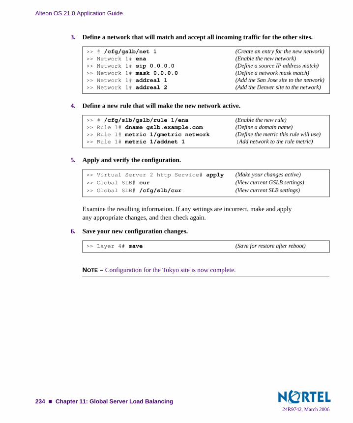
Alteon OS 21.0 Application Guide
3. Define a network that will match and accept all incoming traffic for the other sites.
4. Define a new rule that will make the new network active.
5. Apply and verify the configuration.
Examine the resulting information. If any settings are incorrect, make and apply any appropriate changes, and then check again.
6. Save your new configuration changes.
NOTE – Configuration for the Tokyo site is now complete.
>> # /cfg/gslb/net 1 (Create an entry for the new network)>> Network 1# ena (Enable the new network)>> Network 1# sip 0.0.0.0 (Define a source IP address match)>> Network 1# mask 0.0.0.0 (Define a network mask match)>> Network 1# addreal 1 (Add the San Jose site to the network)>> Network 1# addreal 2 (Add the Denver site to the network)
>> # /cfg/slb/gslb/rule 1/ena (Enable the new rule)>> Rule 1# dname gslb.example.com (Define a domain name)>> Rule 1# metric 1/gmetric network (Define the metric this rule will use)>> Rule 1# metric 1/addnet 1 (Add network to the rule metric)
>> Virtual Server 2 http Service# apply (Make your changes active)>> Global SLB# cur (View current GSLB settings)>> Global SLB# /cfg/slb/cur (View current SLB settings)
>> Layer 4# save (Save for restore after reboot)
24R9742, March 2006234 Chapter 11: Global Server Load Balancing

Alteon OS 21.0 Application Guide
Configuring GSLB with RulesGSLB rules can be configured on a per-domain basis to allow dynamic site selection based on time of day for a given domain. The criteria for domain rules are as follows:
Each domain has one or more rules.
Each rule has a metric preference list.
The site selection selects the first rule that matches for the domain and starts with the first metric in the metric preference list of the rule.
Up to 128 rules can be configured, with up to eight metrics per rule. The site selection metric sequence in the default Rule 1 is as follows:
1. Network Preference
The first metric in rule 1 is set to “Network Preference,” which selects the server based on the preferred network of the source IP address for a given domain. If preferred networks are not configured, this metric is not used in the default rule. For more information on configuring pre-ferred networks, see “Configuring GSLB Network Preference” on page 239.
2. None
The second metric in rule 1 is set to “None” in order to allow you to configure the local or availability metric here. The local server or the server with the highest availability is selected before any subsequent metric is used to select other servers.
3. Geographical preference
The third metric in rule 1 is set to “Geographical Preference” so that the IANA-defined geo-graphical region based on the client source IP is used to redirect the request to the client’s region.
4. Least connections
5. Round robin
“Round robin” or random should be the last metric defined in a rule, because they always return a value if there is at least one functional site.
6. None
7. None
8. None
24R9742, March 2006Chapter 11: Global Server Load Balancing 235

Alteon OS 21.0 Application Guide
The last metric in rule 1 should be configured as dnsalways so that the GSLB selection selects at least the local virtual server when all servers are not available. In this case, metric 6 can be configured with DNS always.
Configuring Time-Based Rules
Task 1: Configure the first time-based ruleUsing the base configuration “Configuring Basic GSLB” on page 217, you can define a new time-based rule for certain networks, as follows:
1. Disable the default rule 1, in order to ensure that the time based rule is processed first.
2. Configure the networks to be added to the GSLB rule.
3. Configure a new rule.
4. Specify a start and end time for this rule to be applied.
5. Specify the GSLB metrics to be used to select a site if a server is not selected at first.
Since network metric is the first metric, make sure to add the configured networks to metric 1.
6. Specify the other preferred GSLB metrics.
>> # /cfg/slb/gslb/rule 1/dis (Disable rule 1)
>> # /cfg/slb/gslb/net 43/sip 43.0.0.0/mask 255.0.0.0/addvirt 1/ena>> # /cfg/slb/gslb/net 55/sip 55.0.0.0/mask 255.0.0.0/addreal 10/ena>> # /cfg/slb/gslb/net 56/sip 56.0.0.0/mask 255.0.0.0/addreal 10/ena
>> # /cfg/slb/gslb/rule 2 (Select rule 2)
>> Rule 2# start 7 00/end 18 00/ena (From 7am until 6PM)>> Rule 2# ena (Enable the rule)
>> # /cfg/slb/gslb/rule 2/metric 1/gmetric network>> # /cfg/slb/gslb/rule 2/metric 1/addnet 43/addnet 55/addnet 56
>> # /cfg/slb/gslb/rule 2/metric 2/gmetric geographical>> # /cfg/slb/gslb/rule 2/metric 3/gmetric roundrobin
24R9742, March 2006236 Chapter 11: Global Server Load Balancing

Alteon OS 21.0 Application Guide
Task 2: Configure the second time-based ruleUsing the steps in “Task 1: Configure the first time-based rule” on page 236, configure another rule with the following parameters.
7. Add the rule to the configured virtual server. Using the basic GSLB example, add the fol-lowing command to the virtual server configuration steps on page 224 on page 230.
8. Apply and save the configuration.
>> # /cfg/slb/gslb/net 48/sip 48.0.0.0/mask 240.0.0.0/addreal 2/en>> # /cfg/slb/gslb/rule 4/start 18 00/end 7 00/ena>> # /cfg/slb/gslb/rule 4/metric 1/gmetric network/addnet 48>> # /cfg/slb/gslb/rule 4/metric 2/gmetric geographical>> # /cfg/slb/gslb/rule 4/metric 3/gmetric random
>> # /cfg/slb/virt 1/addrule 2/addrule 4 (Add rules 2 and 4 to the virtual server/domain)
>> Rule 2 Metric 4# apply>> Rule 2 Metric 4# save
24R9742, March 2006Chapter 11: Global Server Load Balancing 237
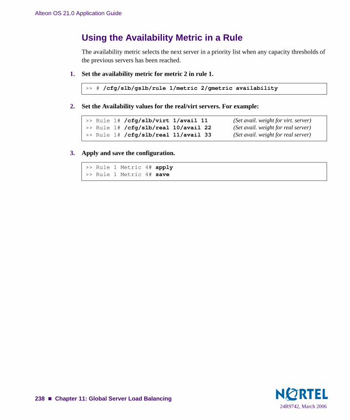
Alteon OS 21.0 Application Guide
Using the Availability Metric in a RuleThe availability metric selects the next server in a priority list when any capacity thresholds of the previous servers has been reached.
1. Set the availability metric for metric 2 in rule 1.
2. Set the Availability values for the real/virt servers. For example:
3. Apply and save the configuration.
>> # /cfg/slb/gslb/rule 1/metric 2/gmetric availability
>> Rule 1# /cfg/slb/virt 1/avail 11 (Set avail. weight for virt. server)>> Rule 1# /cfg/slb/real 10/avail 22 (Set avail. weight for real server)>> Rule 1# /cfg/slb/real 11/avail 33 (Set avail. weight for real server)
>> Rule 1 Metric 4# apply>> Rule 1 Metric 4# save
24R9742, March 2006238 Chapter 11: Global Server Load Balancing

Alteon OS 21.0 Application Guide
Configuring GSLB Network PreferenceAlteon OS software allows clients to select GSLB sites based on where the client is located. This is implemented by configuring network preference. Network preference selects the server based on the preferred network of the source IP address for a given domain. The preferred network con-tains a subset of the servers for the domain.
The following example, illustrated in Figure 11-4 on page 240, shows how to create rules based on client network preference. Two client networks, A and B, are configured in the net-work preference rule on the master switch at Site 4. Client A with a subnet address of 205.178.13.0 is configured with a network preference rule for preferred Sites 1 and 3. Client B, with a subnet address of 204.165.0.0, is configured a network preference rule for preferred Sites 2 and 4.
24R9742, March 2006Chapter 11: Global Server Load Balancing 239

Alteon OS 21.0 Application Guide
Client A, with a source IP address of 205.178.13.10, initiates a request that is sent to the local DNS server. The local DNS server is configured to forward requests to the DNS server at Site 4. The GbESM at Site 4 looks up its network preference and finds Client A prefers to connect to Sites 1 or 3. Similarly, Client B’s requests are always forwarded to Sites 2 or 4.
Figure 11-4 Configuring Client Proximity Table
NOTE – Alteon OS allows you to configure up to 128 preferred client networks. Each network can contain up to 64 real servers.
Internet
GbESM
Client Site B
DNSRequest
Client Site A
DNSRequest
205.178.13.0 204.165.0.0
IF: 1.1.1.1 / 24 VIP: 1.1.1.100
IF: 2.2.2.2 / 24 VIP: 2.2.2.100
IF: 3.3.3.3 / 16VIP: 3.3.3.100
IF: 4.4.4.4 / 24 VIP: 4.4.4.100Web
ServersWeb
Servers
DNS DNS
DNS DNS
Site 3Site 2
Site 4Site 1
WebServers
WebServers
GbESM
Master switch returnsClient's request with theVIP of the preferred site
2. The master switch looks through its network preference rule, and responds to the DNS request by providing the virtual IP address of the preferred site.
3. The client sends out a new request and connects to the preferred site.
PrefersSites 1 and 3
PrefersSites 2 and 4
1. Client sites A and B send requests to their DNS servers which are forwarded to the master switch at Site 4.
GbESM
GbESM
24R9742, March 2006240 Chapter 11: Global Server Load Balancing

Alteon OS 21.0 Application Guide
Use the following commands to configure network preferences on the GbESM at Site 4:
Using this configuration, the DNS request for “nortelnetworks.com” from client IP 205.178.13.0 will receive a DNS response with only the virtual server IP address of Site 1, if Site 1 has less load than Site 3.
>> # /cfg/slb/gslb/net 1/ (Select Network 1)>> Network 1# sip 205.178.13.0 (Assign source address for Client A)>> Network 1# mask 255.255.255.0 (Assign the mask for Client A)>> Network 1# addreal 1/addreal 3 (Add real servers 1 and 3)>> # /cfg/slb/gslb/net 2/ (Select Network 2)>> Network 2# sip 204.165.0.0 (Assign source address for Client B)>> Network 2# mask 255.255.0.0 (Assign the mask for Client B)>> Network 2# addreal 2 (Add real server 2)>> Network 2# addvir 4 (Select preferred Site 4)>> # /cfg/slb/gslb/rule 1/metric 1 (Select metric 1-network preference)>> Rule 1 Metric 2# addnet 1/addnet 2 (Add Network 1 and Network 2)
24R9742, March 2006Chapter 11: Global Server Load Balancing 241

Alteon OS 21.0 Application Guide
Configuring GSLB with Proxy IP for Non-HTTP RedirectsTypically, client requests for HTTP applications are automatically redirected to the location with the best response and least load for the requested content. The HTTP protocol has a built-in redirection function that allows requests to be redirected to an alternate site. However, if a client requests a non-HTTP application such as FTP, POP3, or SMTP, then the lack of a redirection function in these applications requires that a proxy IP address be configured on the client port. The client port will initiate a redirect only if resources are unavailable at the first site.
NOTE – This feature should be used as a method of last resort for GSLB implementations in topologies where the remote servers are usually virtual server IP addresses in other application switches.
24R9742, March 2006242 Chapter 11: Global Server Load Balancing
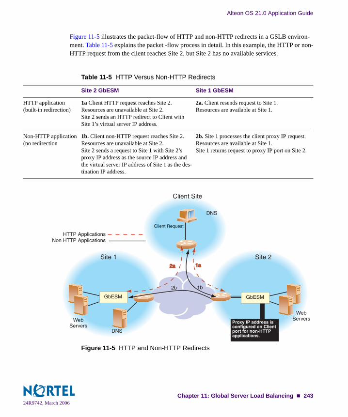
Alteon OS 21.0 Application Guide
Figure 11-5 illustrates the packet-flow of HTTP and non-HTTP redirects in a GSLB environ-ment. Table 11-5 explains the packet -flow process in detail. In this example, the HTTP or non-HTTP request from the client reaches Site 2, but Site 2 has no available services.
Figure 11-5 HTTP and Non-HTTP Redirects
Table 11-5 HTTP Versus Non-HTTP Redirects
Site 2 GbESM Site 1 GbESM
HTTP application(built-in redirection)
1a Client HTTP request reaches Site 2.Resources are unavailable at Site 2.Site 2 sends an HTTP redirect to Client with Site 1’s virtual server IP address.
2a. Client resends request to Site 1.Resources are available at Site 1.
Non-HTTP application(no redirection
1b. Client non-HTTP request reaches Site 2.Resources are unavailable at Site 2.Site 2 sends a request to Site 1 with Site 2’s proxy IP address as the source IP address and the virtual server IP address of Site 1 as the des-tination IP address.
2b. Site 1 processes the client proxy IP request.Resources are available at Site 1.Site 1 returns request to proxy IP port on Site 2.
1a1a2a2a
1b
Client Site
Client Request
Site 1
WebServersWeb
ServersDNS
Site 2
HTTP ApplicationsNon HTTP Applications
Proxy IP address isconfigured on Client port for non-HTTP applications.
DNS
2b
GbESMGbESM
24R9742, March 2006Chapter 11: Global Server Load Balancing 243

Alteon OS 21.0 Application Guide
How Proxy IP WorksFigure 11-6 shows examples of two GSLB sites deployed in San Jose and Denver. The applica-tions being load balanced are HTTP and POP3. Any request that cannot be serviced locally is sent to the peer site. HTTP requests are sent to the peer site using HTTP Redirect. Any other application request will be sent to the peer site using the proxy IP feature.
Figure 11-6 POP3 Request Fulfilled via IP Proxy
The following procedure explains the three-way handshake between the two sites and the cli-ent for a non-HTTP application (POP3).
1. A user POP3 TCP SYN request is received by the virtual server at Site 2. The switch at that site determines that there are no local resources to handle the request.
2. The Site 2 switch rewrites the request such that it now contains a client proxy IP address as the source IP address, and the virtual server IP address at Site 1 as the destination IP address.
3. The switch at Site 1 receives the POP3 TCP SYN request to its virtual server. The request looks like a normal SYN frame, so it performs normal local load-balancing.
4. Internally at Site 1, the switch and the real servers exchange information. The TCP SYN ACK from Site 1’s local real server is sent back to the IP address specified by the proxy IP address.
5. The Site 1 switch sends the TCP SYN ACK frame to Site 2, with Site 1’s virtual server IP address as the source IP address, and Site 2’s proxy IP address as the destination IP address.
Proxy Disabled ForLocal Real Servers
Proxy Enabled ForRemote Server
San Jose Site #1174.14.70.X Network
AB C
D
Proxy Disabled ForLocal Real Servers
Proxy IP Address174.14.70.4
Proxy IP Address200.200.200.4
Internet
200.200.200.X Network
HTTP/POP3Local Servers200.200.200.2200.200.200.3
Remote Server174.14.70.1
Virtual Server200.200.200.1
Denver: Site #2
HTTP/POP3Local Servers174.14.70.2174.14.70.3
Remote Server200.200.200.1
Virtual Server174.14.70.1
Service requests are always served bylocal real servers if available.
If local real servers cannot service the request,the remote server is used via proxy.
Proxy Enabled ForRemote Server
6 4 GbESMGbESM
24R9742, March 2006244 Chapter 11: Global Server Load Balancing

Alteon OS 21.0 Application Guide
6. The switch at Site 1 receives the frame and translates it, using Site 1’s virtual server IP address as the source IP address and the client’s IP address as the destination IP address.
This cycle continues for the remaining frames to transmit all the client’s mail, until a FIN frame is received.
Configuring Proxy IP AddressesThe switch at Site 1 in San Jose is configured with switch port 6 connecting to the default gate-way and real server 3 represents the remote server in Denver.
The following commands are used at Site 1 in San Jose to configure the proxy IP address for the remote server in Denver:
For more information on proxy IP address, see “Proxy IP Addresses” on page 190.
If you want to configure proxy IP addresses on Site 2, the following commands are issued on the Denver switch:
>> # /cfg/slb/pip (Select proxy IP address menu)>> Proxy IP address# type port (Use port-based proxy IP)>> Proxy IP address# add 200.200.200.4 (Set unique proxy IP address)>> # /cfg/slb/port 6/proxy enable (Enable proxy on the port)>> Proxy IP address /cfg/slb/real 1/proxy dis(Disable local real server proxy)>> Real server 1# /cfg/slb/real 2/proxy dis(Disable proxy for local server)>> Real server 2# /cfg/slb/real 3/proxy ena(Enable proxy for remote server)>> Real server 3# apply (Apply configuration changes)>> Real server 3# save (Save configuration changes)
>> # /cfg/slb/pip (Select proxy IP address menu)>> Proxy IP address# type port (Use port-based proxy IP)>> Proxy IP address# add 174.14.70.4 (Set unique proxy IP address)>> # /cfg/slb/port 4/proxy enable (Enable proxy on the port)>> Proxy IP address# /cfg/slb/real 1/proxy dis(Disable local real server proxy)>> Real server 1# /cfg/slb/real 2/proxy dis(Disable local real server proxy)>> Real server 2# /cfg/slb/real 3/proxy ena(Enable proxy for remote server)>> Real server 3# apply (Apply configuration changes)>> Real server 3# save (Save configuration changes)
24R9742, March 2006Chapter 11: Global Server Load Balancing 245
Alteon OS 21.0 Application Guide
GSLB DNS PersistenceGSLB DNS Persistence selects a server based on previously cached source IP addresses. This caching only allows up to two servers for each source IP address in the cache. Cache entries can then be forwarded to other remote sites for addition to their caches. After the timeout is reached for the cached entry, it is deleted from the cache. Remote sites are not informed to delete the cache entry when the local site does.
Using Border Gateway Protocol for GSLBBorder Gateway Protocol (BGP)-based GSLB utilizes the Internet’s routing protocols to local-ize content delivery to the most efficient and consistent site. This is done by using a shared IP block that co-exists in each Internet Service Provider’s (ISP’s) network and is then advertised, using BGP, throughout the Internet.
Because of the way IP routing works, BGP-based GSLB allows for the routing protocols to route DNS requests to the closest location, which then returns IP addresses of that particular site, locking in the requests to that site. In effect, the Internet is making the decision of the best location for you, avoiding the need for advanced GSLB.
Some corporations use more than one ISP as a way to increase the reliability and bandwidth of their Internet connection. Enterprises with more than one ISP are referred to as being multi-homed. Instead of multi-homing a network to several other networks, BGP-based GSLB enables you to multi-home a particular piece of content (DNS information) to the Internet by distributing the IP blocks that contain that content to several sites.
When using DNS to select the site, a single packet is used to make the decision so that the request will not be split to different locations. Through the response to the DNS packet, a client is locked in to a particular site, resulting in efficient, consistent service that cannot be achieved when the content itself is shared.
For example, in multi-homing, you can connect a data center to three different Internet provid-ers and have one DNS server that has the IP address 1.1.1.1. In this case, all requests can be received via any given feed but are funneled to the same server on the local network. In BGP-based GSLB, the DNS server (with the IP address 1.1.1.1) is duplicated and placed local to the peering point instead of having a local network direct traffic to one server.
24R9742, March 2006246 Chapter 11: Global Server Load Balancing
Alteon OS 21.0 Application Guide
When a particular DNS server receives a request for a record (in this case, the GbESM), it returns with the IP address of a virtual server at the same site. This can be achieved using the local option (/cfg/slb/gslb/rule 1/metric 2/gmetric local) in the GSLB config-uration. If one site is saturated, then the switch will failover and deliver the IP address of a more available site.
For more information on configuring your switch to support BGP routing, see “Border Gate-way Protocol” on page 121.
Verifying GSLB OperationUse your browser to request the configured service (www.gslb.example.com in the previ-ous example).
Examine the /info/slb and /info/slb/gslb information on each switch.
Check to see that all SLB and GSLB parameters are working according to expectation. If necessary, make any appropriate configuration changes and then check the information again.
Examine the /stats/slb and /stats/slb/gslb statistics on each switch.
24R9742, March 2006Chapter 11: Global Server Load Balancing 247

Alteon OS 21.0 Application Guide
24R9742, March 2006248 Chapter 11: Global Server Load Balancing

CHAPTER 12Filtering
This chapter provides a conceptual overview of filters and includes configuration examples showing how filters can be used for network security and Network Address Translation (NAT). The following topics are discussed in this chapter:
“Overview” on page 250. This section describes the benefits and filtering criteria to allow for extensive filtering at the IP and TCP/UDP levels.
“Filtering Benefits” on page 250
“Filtering Criteria” on page 250
“Stacking Filters” on page 252
“Overlapping Filters” on page 253
“The Default Filter” on page 253
“VLAN-based Filtering” on page 255
“Optimizing Filter Performance” on page 257
“Filter Logs” on page 257
“IP Address Ranges” on page 259
“Cache-Enabled versus Cache-Disabled Filters” on page 259
“TCP Rate Limiting” on page 260. This section explains how TCP rate limiting allows you to monitor the number of new TCP connections within a configurable time window. “Tunable Hash for Filter Redirection” on page 265 allows you to select any hash parame-ter for filter redirection.“Filter-based Security” on page 266. This section provides an example of configuring fil-ters for providing the best security. “Network Address Translation” on page 272. This section provides two examples: Internal client access to the Internet and external client access to the server.“Matching TCP Flags” on page 279 and “Matching ICMP Message Types” on page 284. Describes the ACK filter criteria which provides greater filtering flexibility and lists ICMP message types that can be filtered respectively.
24R9742, March 2006249
Alteon OS 21.0 Application Guide
OverviewGbE Switch Modules are used to deliver content efficiently and secure your servers from unau-thorized intrusion, probing, and Denial-of-Service (DoS) attacks. Alteon OS includes exten-sive filtering capabilities at the IP and TCP/UDP levels.
Filtering BenefitsLayer 3 (IP) and Layer 4 (TCP port) filtering give the network administrator a powerful tool with the following benefits:
Increased security for server networksFilters can be configured to allow or deny traffic according to various IP address, protocol, and Layer 4 port criteria. You can also secure your switch from further virus attacks by allowing you to configure the switch with a list of potential offending string patterns. For more information, see “Layer 7 Deny Filters” on page 428.This gives the administrator control over the types of traffic permitted through the switch. Any filter can be optionally configured to generate system log messages for increased security visibility.
Used to map the source or destination IP addresses and ports
Generic Network Address Translation (NAT) can be used to map the source or destination IP addresses and the ports of private network traffic to or from advertised network IP addresses and ports.
Filtering CriteriaUp to 1024 filters can be configured on the GbE Switch Module. Descriptive names can be used to define filters. Each filter can be set to allow, deny, redirect, or translate traffic based on any combination of the following filter options:
sip: source IP address or range (see “IP Address Ranges” on page 259)
dip: destination IP address or range (dip and dmask)
proto: protocol number or name as shown in Table 12-1 on page 251.
250 Chapter 12: Filtering24R9742, March 2006

Alteon OS 21.0 Application Guide
sport: TCP/UDP application or source port as shown in Table 10-3 on page 182, or source port range (such as 31000-33000)
NOTE – The service number specified on the switch must match the service specified on the server.
dport: TCP/UDP application or destination port as shown in Table 10-3 on page 182, or destination port range (such as 31000-33000)invert: reverse the filter logic in order to activate the filter whenever the specified condi-tions are not met.Advanced filtering options such as TCP flags (page 279) or ICMP message types (page 284) are also available.
Using these filter criteria, you could create a single filter that blocks external Telnet traffic to your main server except from a trusted IP address. Another filter could warn you if FTP access is attempted from a specific IP address. Another filter could redirect all incoming e-mail traffic to a server where it can be analyzed for spam. The options are nearly endless.
Table 12-1 Well-Known Protocol Types
Number Protocol Name
1261789112
icmpigmptcpudpospfvrrp
Chapter 12: Filtering 25124R9742, March 2006

Alteon OS 21.0 Application Guide
Filtering ActionsA filtering action (/cfg/slb/filt/action) instructs the filter what to do once the filtering criteria are matched.
allow—Allow the frame to pass (by default).deny—Discard frames that fit this filter’s profile. This can be used for building basic security profiles.redir—Redirect frames that fit this filter’s profile, such as for web cache redirection. In addition, Layer 4 processing must be activated using the /cfg/slb/on command).nat—Perform generic Network Address Translation (NAT). This can be used to map the source or destination IP address and port information of a private network scheme to/from the advertised network IP address and ports. This is used in conjunction with the nat option (mentioned in this table) and can also be combined with proxies. goto—Allows the user to specify a target filter ID that the filter search should jump to when a match occurs. The “goto” action causes filter processing to jump to a designated filter, effectively skipping over a block of filter IDs. Filter searching will then continue from the designated filter ID. To specify the new filter to goto, use the /cfg/slb/filt/adv/goto command.
Stacking FiltersStacking filters are assigned and enabled on a per-port basis. Each filter can be used by itself or in combination with any other filter on any given switch port. The filters are numbered 1 through 1024 on GbE Switch Modules. When multiple filters are stacked together on a port, the filter’s number determines its order of precedence: the filter with the lowest number is checked first. When traffic is encountered at the switch port, if the filter matches, its config-ured action takes place and the rest of the filters are ignored. If the filter criteria do not match, the next filter is tried.
As long as the filters do not overlap, you can improve filter performance by making sure that the most heavily utilized filters are applied first. For example, consider a filter system where the Internet is divided according to destination IP address:
Figure 12-1 Assigning Filters According to Range of Coverage
Assuming that traffic is distributed evenly across the Internet, the largest area would be the most utilized and is assigned to Filter 1. The smallest area is assigned to Filter 4.
Allow Deny Redirect
Filtering by Destination IP Address Ranges
Deny0.0.0.0 255.255.255.255
Filter 1Filter 3Filter 4Filter 2
252 Chapter 12: Filtering24R9742, March 2006

Alteon OS 21.0 Application Guide
Overlapping FiltersFilters are permitted to overlap, although special care should be taken to ensure the proper order of precedence. When overlapping filters are present, the more specific filters (those that target fewer addresses or ports) should be applied before the generalized filters.
Example:
Figure 12-2 Assigning Filters to Overlapping Ranges
In this example, Filter 2 must be processed prior to Filter 3. If Filter 3 was permitted to take precedence, Filter 2 could never be triggered.
The Default FilterBefore filtering can be enabled on any given port, a default filter should be configured. This filter handles any traffic not covered by any other filter. All the criteria in the default filter must be set to the full range possible (any). For example:
Figure 12-3 Assigning a Default Filter
AllowRedirect
Filtering by Destination IP Address Ranges
Deny0.0.0.0 255.255.255.255
Filter 1Filter 3 Filter 2
Allow Redirect
Filtering by Destination IP Address Ranges
Deny0.0.0.0 255.255.255.255
Filter 1Filter 1024 Filter 2
Chapter 12: Filtering 25324R9742, March 2006

Alteon OS 21.0 Application Guide
In this example, the default filter is defined as Filter 1024 in order to give it the lowest order of precedence. All matching criteria in Filter 1024 are set to the any state. If no other filter acts on the traffic, Filter 1024 processes it, denying and logging unwanted traffic.
Default filters are recommended (but not required) when configuring filters for IP traffic con-trol and redirection. Using default filters can increase session performance but takes some of the session binding resources. If you experience an unacceptable number of binding failures, as shown in the Server Load Balancing Maintenance Statistics (/stats/slb/maint), you may wish to remove some of the default filters.
>> # /cfg/slb/filt 1024 (Select the default filter)>> Filter 1024# sip any (From any source IP addresses)>> Filter 1024# dip any (To any destination IP addresses)>> Filter 1024# proto any (For any protocols)>> Filter 1024# action deny (Deny matching traffic)>> Filter 1024# name deny unwanted traffic (Provide a descriptive name for the filter)>> Filter 1024# ena (Enable the default filter)>> Filter 1024# adv (Select the advanced menu)>> Filter 1024 Advanced# log enable (Log matching traffic to syslog)
254 Chapter 12: Filtering24R9742, March 2006

Alteon OS 21.0 Application Guide
VLAN-based FilteringFilters are applied per switch, per port, or per VLAN. VLAN-based filtering allows a single switch to provide differentiated services for multiple customers, groups, or departments. For example, you can define separate filters for Customers A and B on the same switch on two dif-ferent VLANs. If VLANs are assigned based on data traffic, for example, ingress traffic on VLAN 1, egress traffic on VLAN 2, and management traffic on VLAN 3, filters can be applied accordingly to the different VLANs.
In the following example shown in Figure 12-4, Filter 2 is configured to allow local clients on VLAN 20 to browse the Web, and Filter 3 is configured to allow local clients on VLAN 30 to Telnet anywhere outside the local intranet. Filter 1024 is configured to deny ingress traffic from VLAN 70.
Figure 12-4 VLAN-based Filtering
InternetInternet Filter 2
Filter 3
Filter 1024
Unique filters perVLAN (up to 1024)Unique filters perVLAN (up to 1024)
GbESM
Chapter 12: Filtering 25524R9742, March 2006

Alteon OS 21.0 Application Guide
Configuring VLAN-based Filtering
1. Configure filter 2 to allow local clients to browse the Web and then assign VLAN 20 to the filter.
The filter must recognize and allow TCP traffic from VLAN 20 to reach the local client destina-tion IP addresses if originating from any HTTP source port:
All clients from other VLANs will be ignored.
2. Configure filter 3 to allow local clients to Telnet anywhere outside the local intranet and then assign VLAN 30 to the filter.
The filter must recognize and allow TCP traffic to reach the local client destination IP addresses if originating from a Telnet source port:
>> # /cfg/slb/filt 2 (Select the menu for Filter 2)>> Filter 2# sip any (From any source IP address)>> Filter 2# dip 205.177.15.0 (To base local network dest. address)>> Filter 2# dmask 255.255.255.0 (For entire subnet range)>> Filter 2# proto tcp (For TCP protocol traffic)>> Filter 2# sport http (From any source HTTP port)>> Filter 2# dport any (To any destination port)>> Filter 2# action allow (Allow matching traffic to pass)>> Filter 2# vlan 20 (Assign VLAN 20 to Filter 2)>> Filter 2# ena (Enable the filter)
>> # /cfg/slb/filt 3 (Select the menu for Filter 3)>> Filter 3# sip any (From any source IP address)>> Filter 3# dip 205.177.15.0 (To base local network dest. address)>> Filter 3# dmask 255.255.255.0 (For entire subnet range)>> Filter 3# proto tcp (For TCP protocol traffic)>> Filter 3# sport telnet (From a Telnet port)>> Filter 3# dport any (To any destination port)>> Filter 3# action allow (Allow matching traffic to pass)>> Filter 3# name allow clients to telnet (Provide a descriptive name for the filter)>> Filter 3# vlan 30 (Assign VLAN 30 to Filter 3)>> Filter 3# ena (Enable the filter)
256 Chapter 12: Filtering24R9742, March 2006

Alteon OS 21.0 Application Guide
3. Configure Filter 1024 to deny traffic and then assign VLAN 70 to the filter.
As a result, ingress traffic from VLAN 70 is denied entry to the switch.
Optimizing Filter PerformanceFilter efficiency can be increased by placing filters that are used most often near the beginning of the filtering list.
It is a recommended practice to number filters in small increments (5, 10, 15, 20, etc.) to make it easier to insert filters into the list at a later time. However, as the number of filters increases, you can improve performance by minimizing the increment between filters. For example, fil-ters numbered 2, 4, 6, and 8 are more efficient than filters numbered 20, 40, 60, and 80. Peak processing efficiency is achieved when filters are numbered sequentially beginning with 1.
Filter LogsTo provide enhanced troubleshooting and session inspection capability, packet source and des-tination IP addresses are included in filter log messages. Filter log messages are generated when a Layer 3/Layer 4 filter is triggered and has logging enabled. The messages are output to the management module, system host log (syslog), and the Web-based interface message window.
>> # /cfg/slb/filt 1024 (Select the menu for Filter 1024)>> Filter 1024# sip any (From any source IP address)>> Filter 1024# dip 205.177.15.0 (To base local network dest. address)>> Filter 1024# dmask 255.255.255.0 (For entire subnet range)>> Filter 1024# proto tcp (For TCP protocol traffic)>> Filter 1024# sport http (From a Telnet port)>> Filter 1024# dport any (To any destination port)>> Filter 1024# action deny (Allow matching traffic to pass)>> Filter 1024# vlan 70 (Assign VLAN 70 to Filter 1024)>> Filter 1024# ena (Enable the filter)
Chapter 12: Filtering 25724R9742, March 2006

Alteon OS 21.0 Application Guide
Example: A network administrator has noticed a significant number of ICMP frames on one portion of the network and wants to determine the specific sources of the ICMP messages. The administrator uses the Command Line Interface (CLI) to create and apply the following filter:
When applied to one or more switch ports, this simple filter rule will produce log messages that show when the filter is triggered, and what the IP source and destination addresses were for the ICMP frames traversing those ports.
Example: Filter log message output is shown below, displaying the filter number, port, source IP address, and destination IP address:
>> # /cfg/slb/filt 15 (Select filter 15)>> Filter 15# sip any (From any source IP address)>> Filter 15# dip any (To any destination IP address)>> Filter 15# action allow (Allows matching traffic to pass)>> Filter 15# name allow matching traffic (Provide a descriptive name for the filter)>> Filter 15# proto icmp (For the ICMP protocol)>> Filter 15# ena (Enable the filter)>> Filter 15# adv/log enable (Log matching traffic to syslog)>> Filter 15 Advanced# /cfg/slb/port 7 (Select a switch port to filter)>> SLB port 7# add 15 (Add the filter to the switch port)>> SLB port 7# filt ena (Enable filtering on the switch port)>> SLB port 7# apply (Apply the configuration changes)>> SLB port 7# save (Save the configuration changes)
slb: filter 15 fired on port INT7, 206.118.93.110 -> 20.10.1.10
258 Chapter 12: Filtering24R9742, March 2006

Alteon OS 21.0 Application Guide
IP Address RangesYou can specify a range of IP addresses for filtering both the source and/or destination IP address for traffic. When a range of IP addresses is needed, the source IP (sip) address or des-tination IP (dip) address defines the base IP address in the desired range. The source mask (smask) or destination mask (dmask) is the mask that is applied to produce the range.
For example, to determine if a client request’s destination IP address should be redirected to the cache servers attached to a particular switch, the destination IP address is masked (bit-wise AND) with the dmask and then compared to the destination IP address.
As another example, the switch could be configured with two filters so that each would handle traffic filtering for one half of the Internet. To do this, you could define the following parameters:
Cache-Enabled versus Cache-Disabled FiltersTo improve efficiency, by default, the GbE Switch Module performs filter processing only on the first frame in each session. Subsequent frames in the session are assumed to match the same criteria and are automatically treated in the same way as the initial frame. These filters create a session entry in the switch and are known as cache-enabled.
Some types of filtering (TCP flag and ICMP message type filtering) require each frame in the session to be filtered separately. These filters are known as cache-disabled.
All filters are cache-enabled by default. To change the status of a filter, use the following com-mands:
NOTE – Cache-enabled filters should not be applied to the same ports as cache-disabled filters. Otherwise, the cache-disabled filters could potentially be bypassed for frames matching the cache-enabled criteria.
Table 12-2 Filtering IP Address Ranges
Filter Internet Address Range dip dmask
1 0.0.0.0 - 127.255.255.255 0.0.0.0 128.0.0.0
2 128.0.0.0 - 255.255.255.255 128.0.0.0 128.0.0.0
>> # /cfg/slb/filt <filter number>/adv (Select the advanced filter menu)>> Filter 1 Advanced # cache ena|dis (Enable or disable filter caching)
Chapter 12: Filtering 25924R9742, March 2006
Alteon OS 21.0 Application Guide
TCP Rate LimitingAlteon OS allows you to prevent a client or a group of clients from claiming all the TCP resources on the servers. This is done by monitoring the rate of incoming TCP connection requests to a virtual IP address and limiting the client requests with a known set of IP addresses.
The TCP rate limit is defined as the maximum number of TCP connection requests within a configured time window. The switch monitors the number of new TCP connections and when it exceeds the configured limit, any new TCP connection request is blocked. When this occurs, the client is said to be held down. The client is held down for a specified duration of time, after which new TCP connection requests from the client are allowed to pass through again.
NOTE – Both, time window and hold duration are the same for all TCP rate filters.
Figure 12-5 on page 261 shows four clients configured for TCP rate limits based on source IP address. Clients 1 and 4 have the same TCP rate limit of 10 connections per second. Client 2 has a TCP rate limit of 20 connections per second. Client 3 has a TCP rate limit of 30 connec-tions per second.
When the rate of new TCP connections from clients 1, 2, 3, and 4 reach the configured thresh-old, any new connection request from the client is blocked for a pre-determined amount of time. If the client’s IP address and the configured filter do not match, then the default filter is applied.
260 Chapter 12: Filtering24R9742, March 2006

Alteon OS 21.0 Application Guide
In Figure 12-5, the default filter 1024 configured for Any is applied for all other connection requests.
Figure 12-5 Configuring Clients with Different Rates
Configuring TCP Rate Limiting FiltersTCP rate limiting can be configured for all filter types (allow, redir, SIP, and DIP) and parame-ters. You can specify the source IP address and mask options in the filter configuration menu to monitor a client or a group of clients. The destination IP address and mask options are used to monitor connections to a virtual IP address or a group of virtual IP addresses.
Basic TCP Rate Limiting FilterThe following example shows how to configure TCP rate limiting for Filter 10 in Figure 12-5.
1. Enable TCP rate limiting for the filter.
2. Configure maximum number of TCP connections.
The maxcon value is specified in units of 10. The value of 3 indicates a total of 30 TCP con-nections.
>> # /cfg/slb/filt 10/adv/tcp>> TCP Advanced menu # tcplim ena (Enable TCP rate limiting)
>> TCP Advanced menu # maxcon 3 (Set the max. number of connections)
InternetInternet
BladeCenterBladeCenter
Real Servers
Filter 1024: Allow AnyFilter 1024: Allow Any
GbESM
Chapter 12: Filtering 26124R9742, March 2006

Alteon OS 21.0 Application Guide
3. Set the timewin parameter and calculate the total time window in seconds.
The total time window is a multiple of fastage (for information on fastage, see the Con-figuration chapter in the Alteon OS Command Reference). The total time window is calculated with the following equation:
Total Time window = timewin x fastage
If the default value for fastage is 1 second, then the configured total time window is 3 sec-onds.
NOTE – From Step 2 and 3, the TCP rate limit defined as the maximum number of connections over a specified time window is 30 TCP connections for every 3 seconds (or 10 TCP connec-tions per second).
For a small site, 30 TCP connections per second provides a good indication if your site is being attacked. The default is 100 TCP connections per second. For larger sites, TCP rate limit greater than 2550 connection per second indicates the possibility that your switch is under attack.
4. Set the holddur parameter and calculate the hold down time in minutes.
The hold down time is a multiple of slowage (for information on slowage, see the Config-uration chapter in the Alteon OS Command Reference). The hold down time is calculated with the following equation:
Hold down time = holddur x slowage
If slowage is set to the default value of 0 (2 minutes), then the configured value for hold down time is
Hold down time = 2 x 2 = 4 minutes
If a client exceeds the TCP rate limit, then the client is not allowed to make any new TCP con-nections for 4 minutes. The following two configuration examples illustrate how to use TCP rate limiting to limit user access based on source IP address and virtual IP address.
>> # /cfg/slb/adv/timewin 3 (Set the time window)
>> # /cfg/slb/adv/holddur 2 (Set the hold duration)
262 Chapter 12: Filtering24R9742, March 2006

Alteon OS 21.0 Application Guide
TCP Rate Limiting Filter Based on Source IP AddressThis example shows how to define a filter that limits clients with IP address 30.30.30.x to 150 TCP connections per second. Once a user exceeds that limit, they are not allowed any new TCP connections for 10 minutes.
Configure the following on the switch:
Fastage and slowage are set at their default values:
Fastage = 0 (1 sec) slowage = 0 (2 minutes).
Time window = timewin x fastage = 1 x 1 second = 1 second
Hold down time = holddur x slowage = 5 x 2 minutes = 10 minutes
Max rate = maxcon/time window = 150 connections/1 second = 150 connections/second
Any client with source IP address equal to 30.30.30.x is allowed to make 150 new TCP con-nections per second to any single destination. When the rate limit of 150 is met, the hold down time takes effect and the client is not allowed to make any new TCP connections to the same destination for 10 minutes.
>> # /cfg/slb/filt 100/ena (Enable the filter)>> Filter 100 # sip 30.30.30.0 (Specify the source IP address)>> Filter 100 # smask 255.255.255.0 (Specify the source IP address mask)>> Filter 100 # adv/tcp (Select the advanced filter menu)>> TCP advanced# tcplim en (Enable TCP rate limiting)>> TCP advanced# maxconn 150 (Specify the maximum connections)>> TCP advanced# /cfg/slb/adv (Select the Layer 4 advanced menu)>> Layer 4 Advanced # timewin 1 (Set the time window for the session)>> Layer 4 Advanced # holddur 5 (Set the hold duration for the session)
Chapter 12: Filtering 26324R9742, March 2006
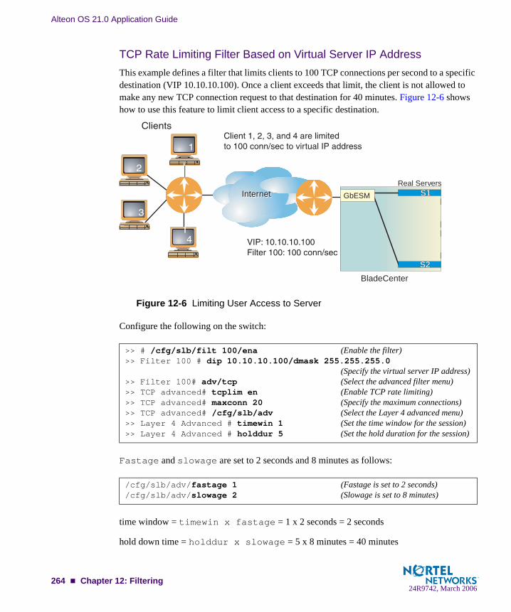
Alteon OS 21.0 Application Guide
TCP Rate Limiting Filter Based on Virtual Server IP AddressThis example defines a filter that limits clients to 100 TCP connections per second to a specific destination (VIP 10.10.10.100). Once a client exceeds that limit, the client is not allowed to make any new TCP connection request to that destination for 40 minutes. Figure 12-6 shows how to use this feature to limit client access to a specific destination.
Figure 12-6 Limiting User Access to Server
Configure the following on the switch:
Fastage and slowage are set to 2 seconds and 8 minutes as follows:
time window = timewin x fastage = 1 x 2 seconds = 2 seconds
hold down time = holddur x slowage = 5 x 8 minutes = 40 minutes
>> # /cfg/slb/filt 100/ena (Enable the filter)>> Filter 100 # dip 10.10.10.100/dmask 255.255.255.0
(Specify the virtual server IP address)>> Filter 100# adv/tcp (Select the advanced filter menu)>> TCP advanced# tcplim en (Enable TCP rate limiting)>> TCP advanced# maxconn 20 (Specify the maximum connections)>> TCP advanced# /cfg/slb/adv (Select the Layer 4 advanced menu)>> Layer 4 Advanced # timewin 1 (Set the time window for the session)>> Layer 4 Advanced # holddur 5 (Set the hold duration for the session)
/cfg/slb/adv/fastage 1 (Fastage is set to 2 seconds)/cfg/slb/adv/slowage 2 (Slowage is set to 8 minutes)
InternetInternet
BladeCenterBladeCenter
Real ServersS1S1
S2S2
GbESM
264 Chapter 12: Filtering24R9742, March 2006

Alteon OS 21.0 Application Guide
max rate = maxcon/time window = 200 connections/2 seconds = 100 connections/second
All clients are limited to 100 new TCP connections/second to the server. If a client exceeds this rate, then the client is not allowed to make any new TCP connections to the server for 40 min-utes.
NOTE – All SLB sessions on the switch are affected when you make changes to the fastage or slowage parameters.
Tunable Hash for Filter RedirectionAlteon OS allows you to choose a number of options when using the hash parameter for filter redirection. Hashing can be based on source IP address, destination IP address, both, or source IP address and source port. For example:
1. Configure hashing based on source IP address:
Hashing on the 24-bit source IP address ensures that client requests access the same cache.
2. Set the metric for the real server group to minmisses or hash.
The source IP address is passed to the real server group for either of the two metrics.
NOTE – If firewall load balancing is enabled on the switch, the firewall load balancing filter which hashes on source and destination IP addresses will override the tunable hash filter.
>> # /cfg/slb/filt 10/ena (Enable the filter)>> Filter 10 # action redir (Specify the redir action)>> Filter 10 # proto tcp (Specify the protocol)>> Filter 10 # group 1 (Specify the group of real servers)>> Filter 10 # rport 3128 (Specify the redirection port)>> Filter 10 # vlan any (Specify the VLAN)>> Filter 10 # adv (Select the advanced filter menu)>> TCP advanced menu # thash sip (Select source IP address for hashing)
>> # /cfg/slb/group 1 (Select the group of real servers)>> Real server group 1 # metric minmiss (Set the metric to minmiss or hash)
Chapter 12: Filtering 26524R9742, March 2006

Alteon OS 21.0 Application Guide
Filter-based SecurityThis section provides an example of configuring filters for providing the best security. It is rec-ommended that you configure filters to deny all traffic except for those services that you spe-cifically wish to allow. Consider the following sample network:
Figure 12-7 Security Topology Example
In this example, the network is made of local clients on a collector switch, a Web server, a mail server, a domain name server, and a connection to the Internet. All the local devices are on the same subnet.
In this example, the administrator wishes to install basic security filters to allow only the fol-lowing traffic:
External HTTP access to the local Web serverExternal SMTP (mail) access to the local mail serverLocal clients browsing the World Wide WebLocal clients using Telnet to access sites outside the intranetDNS traffic
All other traffic is denied and logged by the default filter.
BladeCenterBladeCenter
InternetInternet
266 Chapter 12: Filtering24R9742, March 2006

Alteon OS 21.0 Application Guide
NOTE – Since IP address and port information can be manipulated by external sources, filter-ing does not replace the necessity for a well-constructed network firewall.
Configuring a Filter-Based Security SolutionBefore you begin, you must be connected to the switch CLI as the administrator.
In this example, all filters are applied only to the switch port that connects to the Internet. If intranet restrictions are required, filters can be placed on switch ports connecting to local devices.
Also, filtering is not limited to the few protocols and TCP or UDP applications shown in this example. See Table 10-3 on page 182 for a list of well-known applications ports and Table 12-1 on page 251 for a list of supported protocols.
1. Assign an IP address to each of the network devices.
For this example, the network devices have the following IP addresses on the same IP subnet:
2. At the GbE Switch Module, create a default filter to deny and log unwanted traffic.
The default filter is defined as Filter 1024 in order to give it the lowest order of precedence:
Table 12-3 Web Cache Example: Real Server IP Addresses
Network Device IP address
Local Subnet 205.177.15.0 - 205.177.15.255
Web Server 205.177.15.2
Mail Server 205.177.15.3
Domain Name Server 205.177.15.4
>> # /cfg/slb/filt 1024 (Select the default filter)>> Filter 1024# sip any (From any source IP addresses)>> Filter 1024# dip any (To any destination IP addresses)>> Filter 1024# proto any (For any protocols)>> Filter 1024# action deny (Deny matching traffic)>> Filter 1024# name deny unwanted traffic (Provide a descriptive name for the filter)>> Filter 1024# ena (Enable the default filter)>> Filter 1024# adv/log enable (Log matching traffic to syslog)
Chapter 12: Filtering 26724R9742, March 2006

Alteon OS 21.0 Application Guide
NOTE – Because the proto parameter is not tcp or udp, the source port (sport) and desti-nation port (dport) values are ignored and may be excluded from the filter configuration.
3. Create a filter that will allow external HTTP requests to reach the Web server.
The filter must recognize and allow TCP traffic with the Web server’s destination IP address and HTTP destination port:
4. Create a pair of filters to allow incoming and outgoing mail to and from the mail server.
Filter 2 allows incoming mail to reach the mail server, and Filter 3 allows outgoing mail to reach the Internet:
>> Filter 1024# ../filt 1 (Select the menu for filter 1)>> Filter 1# sip any (From any source IP address)>> Filter 1# dip 205.177.15.2 (To Web server dest. IP address)>> Filter 1# dmask 255.255.255.255 (Set mask for exact dest. address)>> Filter 1# proto tcp (For TCP protocol traffic)>> Filter 1# sport any (From any source port)>> Filter 1# dport http (To an HTTP destination port)>> Filter 1# action allow (Allow matching traffic to pass)>> Filter 1# name allow matching traffic (Provide a descriptive name for the filter)>> Filter 1# ena (Enable the filter)
>> Filter 1# ../filt 2 (Select the menu for filter 2)>> Filter 2# sip any (From any source IP address)>> Filter 2# dip 205.177.15.3 (To mail server dest. IP address)>> Filter 2# dmask 255.255.255.255 (Set mask for exact dest. address)>> Filter 2# proto tcp (For TCP protocol traffic)>> Filter 2# sport any (From any source port)>> Filter 2# dport smtp (To a SMTP destination port)>> Filter 2# action allow (Allow matching traffic to pass)>> Filter 2# ena (Enable the filter)>> Filter 2# ../filt 3 (Select the menu for filter 3)>> Filter 3# sip 205.177.15.3 (From mail server source IP address)>> Filter 3# smask 255.255.255.255 (Set mask for exact source address)>> Filter 3# dip any (To any destination IP address)>> Filter 3# proto tcp (For TCP protocol traffic)>> Filter 3# sport smtp (From a SMTP port)>> Filter 3# dport any (To any destination port)>> Filter 3# action allow (Allow matching traffic to pass)>> Filter 3# ena (Enable the filter)
268 Chapter 12: Filtering24R9742, March 2006

Alteon OS 21.0 Application Guide
5. Create a filter that will allow local clients to browse the Web.
The filter must recognize and allow TCP traffic to reach the local client destination IP addresses if traffic originates from any HTTP source port:
6. Create a filter that will allow local clients to Telnet anywhere outside the local intranet.
The filter must recognize and allow TCP traffic to reach the local client destination IP addresses if originating from a Telnet source port:
7. Create a series of filters to allow Domain Name System (DNS) traffic.
DNS traffic requires four filters; one pair is needed for UDP traffic (incoming and outgoing) and another pair for TCP traffic (incoming and outgoing).
>> Filter 3# ../filt 4 (Select the menu for Filter 4)>> Filter 4# sip any (From any source IP address)>> Filter 4# dip 205.177.15.0 (To base local network dest. address)>> Filter 4# dmask 255.255.255.0 (For entire subnet range)>> Filter 4# proto tcp (For TCP protocol traffic)>> Filter 4# sport http (From any source HTTP port)>> Filter 4# dport any (To any destination port)>> Filter 4# action allow (Allow matching traffic to pass)>> Filter 4# name allow clients Web browse (Provide a descriptive name for the filter)>> Filter 4# ena (Enable the filter)
>> Filter 4# ../filt 5 (Select the menu for Filter 5)>> Filter 5# sip any (From any source IP address)>> Filter 5# dip 205.177.15.0 (To base local network dest. address)>> Filter 5# dmask 255.255.255.0 (For entire subnet range)>> Filter 5# proto tcp (For TCP protocol traffic)>> Filter 5# sport telnet (From a Telnet port)>> Filter 5# dport any (To any destination port)>> Filter 5# action allow (Allow matching traffic to pass)>> Filter 5# ena (Enable the filter)
Chapter 12: Filtering 26924R9742, March 2006

Alteon OS 21.0 Application Guide
For UDP:
Similarly, for TCP:
>> Filter 5# ../filt 6 (Select the menu for Filter 6)>> Filter 6# sip any (From any source IP address)>> Filter 6# dip 205.177.15.4 (To local DNS Server)>> Filter 6# dmask 255.255.255.255 (Set mask for exact dest. address)>> Filter 6# proto udp (For UDP protocol traffic)>> Filter 6# sport any (From any source port)>> Filter 6# dport domain (To any DNS destination port)>> Filter 6# action allow (Allow matching traffic to pass)>> Filter 6# ena (Enable the filter)>> Filter 6# ../filt 7 (Select the menu for Filter 7)>> Filter 7# sip 205.177.15.4 (From local DNS Server)>> Filter 7# smask 255.255.255.255 (Set mask for exact source address)>> Filter 7# dip any (To any destination IP address)>> Filter 7# proto udp (For UDP protocol traffic)>> Filter 7# sport domain (From a DNS source port)>> Filter 7# dport any (To any destination port)>> Filter 7# action allow (Allow matching traffic to pass)>> Filter 7# ena (Enable the filter)
>> Filter 7# ../filt 8 (Select the menu for Filter 8)>> Filter 8# sip any (From any source IP address)>> Filter 8# dip 205.177.15.4 (To local DNS Server)>> Filter 8# dmask 255.255.255.255 (Set mask for exact dest. address)>> Filter 8# proto tcp (For TCP protocol traffic)>> Filter 8# sport any (From any source port)>> Filter 8# dport domain (To any DNS destination port)>> Filter 8# action allow (Allow matching traffic to pass)>> Filter 8# ena (Enable the filter)>> Filter 8# ../filt 9 (Select the menu for Filter 9)>> Filter 9# sip 205.177.15.4 (From local DNS Server)>> Filter 9# smask 255.255.255.255 (Set mask for exact source address)>> Filter 9# dip any (To any destination IP address)>> Filter 9# proto tcp (For TCP protocol traffic)>> Filter 9# sport domain (From a DNS source port)>> Filter 9# dport any (To any destination port)>> Filter 9# action allow (Allow matching traffic to pass)>> Filter 9# ena (Enable the filter)
270 Chapter 12: Filtering24R9742, March 2006

Alteon OS 21.0 Application Guide
8. Assign the filters to the switch port that connects to the Internet.
Alteon OS allows you to add and remove a contiguous block of filters with a single command.
9. Apply and verify the configuration.
Examine the resulting information. If any settings are incorrect, make appropriate changes.
10. Save your new configuration changes.
11. Check the server load balancing information.
Check that all SLB parameters are working according to expectation. If necessary, make any appropriate configuration changes and then check the information again.
NOTE – Changes to filters on a given port do not take effect until the port’s session information is updated (every two minutes or so). To make filter changes take effect immediately, clear the session binding table for the port (see the /oper/slb/clear command in the Alteon OS Command Reference).
>> Filter 9# ../port EXT1 (Select the SLB port 1 to the Internet)>> SLB Port EXT1# add 1-9 (Add filters 1-9 to port EXT1)>> SLB Port EXT1# add 1024 (Add the default filter to port EXT1)>> SLB Port EXT1# filt enable (Enable filtering for port EXT1)
>> SLB Port EXT1# apply (Make your changes active)>> SLB Port EXT1# cur (View current settings)
>> SLB Port EXT1# save (Save for restore after reboot)
>> SLB Port EXT1# /info/slb/dump (View SLB information)
Chapter 12: Filtering 27124R9742, March 2006
Alteon OS 21.0 Application Guide
Network Address TranslationNetwork Address Translation (NAT) is an Internet standard that enables a GbE Switch Module to use one set of IP addresses for internal traffic and a second set of addresses for external traf-fic. GbE Switch Modules use filters to implement NAT.
NAT serves two main purposes:
Provides a type of firewall by hiding internal IP addresses and increases network security.
Enables a company to use more internal IP addresses. Since they're used internally only, there's no possibility of conflict with public IP addresses used by other companies and organizations.
In the following NAT examples, a company has configured its internal network with private IP addresses. A private network is one that is isolated from the global Internet and is, therefore, free from the usual restrictions requiring the use of registered, globally unique IP addresses.
With NAT, private networks are not required to remain isolated. NAT capabilities within the switch allow internal, private network IP addresses to be translated to valid, publicly adver-tised IP addresses and back again. NAT can be configured in one of the following two ways:
Static NAT provides a method for direct mapping of one predefined IP address (such as a publicly available IP address) to another (such as a private IP address)
Dynamic NAT provides a method for mapping multiple IP addresses (such as a group of internal clients) to a single IP address (to conserve publicly advertised IP addresses)
Static NATThe static NAT (non-proxy) example requires two filters: one for the external client-side switch port, and one for the internal, server-side switch port. The client-side filter translates incoming requests for the publicly advertised server IP address to the server’s internal private network address. The filter for the server-side switch port reverses the process, translating the server’s private address information to a valid public address.
272 Chapter 12: Filtering24R9742, March 2006
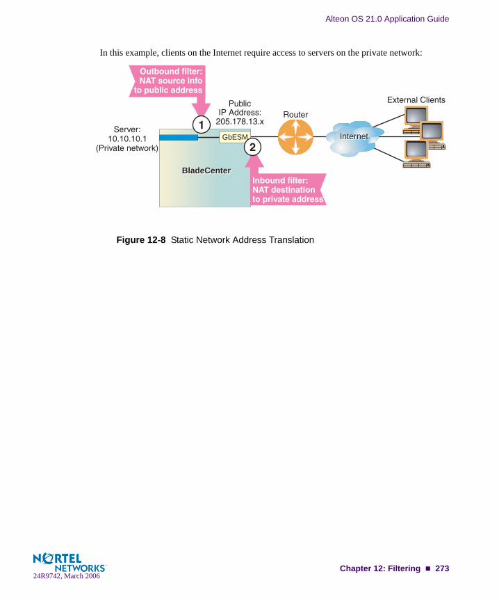
Alteon OS 21.0 Application Guide
In this example, clients on the Internet require access to servers on the private network:
Figure 12-8 Static Network Address Translation
InternetInternet
BladeCenterBladeCenter
GbESM
Chapter 12: Filtering 27324R9742, March 2006

Alteon OS 21.0 Application Guide
Configuring Static NAT
Note the following important points about this configuration:
Within each filter, the smask and dmask values are identical.
All parameters for both filters are identical except for the NAT direction. For Filter 10, nat source is used. For Filter 11, nat dest is used.
Filters for static (non-proxy) NAT should take precedence over dynamic NAT filters (fol-lowing example). Static filters should be given lower filter numbers.
>> # /cfg/slb/filt 10 (Select the menu for outbound filter)>> Filter 10# action nat (Perform NAT on matching traffic)>> Filter 10# nat source (Translate source information)>> Filter 10# sip 10.10.10.0 (From the clients private IP address)>> Filter 10# smask 255.255.255.0 (For the entire private subnet range)>> Filter 10# dip 205.178.13.0 (To the public network address)>> Filter 10# dmask 255.255.255.0 (For the same subnet range)>> Filter 10# ena (Enable the filter)>> Filter 10# adv/proxy disable (Override any proxy IP settings)>> Filter 10 Advanced# /cfg/slb/filt 11 (Select the menu for inbound filter)>> Filter 11# action nat (Use the same settings as outbound)>> Filter 11# nat dest (Reverse the translation direction)>> Filter 11# sip 10.10.10.0 (Use the same settings as outbound)>> Filter 11# smask 255.255.255.0 (Use the same settings as outbound)>> Filter 11# dip 205.178.13.0 (Use the same settings as outbound)>> Filter 11# dmask 255.255.255.0 (Use the same settings as outbound)>> Filter 11# ena (Enable the filter)>> Filter 11# adv/proxy disable (Override any proxy IP settings)>> Filter 11 Advanced# /cfg/slb/port INT5 (Select server-side port)>> SLB port INT5# add 10 (Add the outbound filter)>> SLB port INT5# filt enable (Enable filtering on port INT5)>> SLB port INT5# ../port EXT1 (Select the client-side port)>> SLB port EXT1# add 11 (Add the inbound filter)>> SLB port EXT1# filt enable (Enable filtering on port EXT1)>> SLB port EXT1# apply (Apply configuration changes)>> SLB port EXT1# save (Save configuration changes)
274 Chapter 12: Filtering24R9742, March 2006

Alteon OS 21.0 Application Guide
Dynamic NATDynamic NAT is a many-to-one solution: multiple clients on the private subnet take advantage of a single external IP address, thus conserving valid IP addresses. In this example, clients on the internal private network require TCP/UDP access to the Internet:
Figure 12-9 Dynamic Network Address Translation
You may directly connect the clients to the switch if the total number of clients is less than or equal to the switch ports.
NOTE – Dynamic NAT can also be used to support ICMP traffic for PING.
This example requires a NAT filter to be configured on the switch port that is connected to the internal clients. When the NAT filter is triggered by outbound client traffic, the internal private IP address information on the outbound packets is translated to a valid, publicly advertised IP address on the switch. In addition, the public IP address must be configured as a proxy IP address on the switch port that is connected to the internal clients. The proxy performs the reverse translation, restoring the private network addresses on inbound packets.
InternetInternet
BladeCenterBladeCenterInternalServers
Inbound proxy onpublic address
Outbound filter:NAT source infopublic address
GbESM
Chapter 12: Filtering 27524R9742, March 2006

Alteon OS 21.0 Application Guide
Configuring Dynamic NAT
For more information on proxy IP address, see “Proxy IP Addresses” on page 190.
NOTE – The invert option in this example filter makes this specific configuration easier but is not a requirement for dynamic NAT.
NOTE – Dynamic NAT solutions apply only to TCP/UDP traffic. Also, filters for dynamic NAT should be given a higher numbers than any static NAT filters (see “Static NAT” on page 272).
>> # /cfg/slb/filt 14 (Select the menu for client filter)>> Filter 14# invert ena (Invert the filter logic)>> Filter 14# dip 10.10.10.0 (If the destination is not private)>> Filter 14# dmask 255.255.255.0 (For the entire private subnet range)>> Filter 14# sip any (From any source IP address)>> Filter 14# action nat (Perform NAT on matching traffic)>> Filter 14# nat source (Translate source information)>> Filter 14# ena (Enable the filter)>> Filter 14# adv/proxy enable (Allow proxy IP translation)>> Filter 14 Advanced# cfg/slb/pip (Select the proxy IP address menu)>> Proxy IP Address# pip1 205.178.17.12 (Set proxy IP address)>> Proxy IP Address# ../port INT1 (Select SLB port INT1)>> SLB port INT1# add 14 (Add the filter to port INT1)>> SLB port INT1# filt enable (Enable filtering on port INT1)>> SLB port INT1# proxy ena (Enable proxies on this port)>> SLB port INT1# apply (Apply configuration changes)>> SLB port INT1# save (Save configuration changes)
276 Chapter 12: Filtering24R9742, March 2006

Alteon OS 21.0 Application Guide
FTP Client NATGbE Switch Modules provide NAT services to many clients with private IP addresses. In Alteon OS, an FTP enhancement provides the capability to perform true FTP NAT for dynamic NAT.
Because of the way FTP works in active mode, a client sends information on the control chan-nel, information that reveals their private IP address, out to the Internet. However, the switch filter only performs NAT translation on the TCP/IP header portion of the frame, preventing a client with a private IP address from doing active FTP.
The switch can monitor the control channel and replace the client 's private IP address with a proxy IP address defined on the switch. When a client in active FTP mode sends a port com-mand to a remote FTP server, the switch will look into the data part of the frame and modify the port command as follows:
The real server (client) IP address will be replaced by a public proxy IP address. If VMA is enabled, two proxy IP addresses are used instead of a single one.
The real server (client) port will be replaced with a proxy port.
Figure 12-10 Active FTP for Dynamic NAT
You may directly connect the real servers to the switch if the total number of servers is less than or equal to the switch ports.
InternetInternetBladeCenterBladeCenter
InternalServers Inbound proxy on
public address
Outbound filter:NAT source infopublic address
Real servers10.10.10.x
(Private network)
(Pool of proxy IPaddresses insteadof a single proxyIP address)
205.178.17.12205.178.17.12
INT1 GbESM
Chapter 12: Filtering 27724R9742, March 2006

Alteon OS 21.0 Application Guide
Configuring Active FTP Client NAT
NOTE – The passive mode does not need this feature.
1. Make sure that a proxy IP address is enabled on the filter port.
2. Make sure that a source NAT filter is set up for the port:
For more information on proxy IP address, see “Proxy IP Addresses” on page 190.
3. Enable active FTP NAT using the following command:
4. Apply and save the switch configuration.
>> # /cfg/slb/filt 14 (Select the menu for client filter)>> Filter 14# invert ena (Invert the filter logic)>> Filter 14# dip 10.10.10.0 (If the destination is not private)>> Filter 14# dmask 255.255.255.0 (For the entire private subnet range)>> Filter 14# sip any (From any source IP address)>> Filter 14# action nat (Perform NAT on matching traffic)>> Filter 14# nat source (Translate source information)>> Filter 14# ena (Enable the filter)>> Filter 14# adv/proxy enable (Allow proxy IP translation)>> Filter 14 Advanced# cfg/slb/pip (Select the proxy IP address menu)>> Proxy IP Address# pip1 205.178.17.12 (Set proxy IP address)>> Proxy IP Address# ../port INT1 (Select SLB port INT1)>> SLB port INT1# add 14 (Add the filter to port INT1)>> SLB port INT1# filt enable (Enable filtering on port INT1)>> SLB port INT1# proxy ena (Enable proxies on this port)>> SLB port INT1# apply (Apply configuration changes)>> SLB port INT1# save (Save configuration changes)
>> # /cfg/slb/filt <filter number>/adv/layer7/ftpa ena
278 Chapter 12: Filtering24R9742, March 2006

Alteon OS 21.0 Application Guide
Matching TCP FlagsAlteon OS supports packet filtering based on any of the following TCP flags.
Any filter may be set to match against more than one TCP flag at the same time. If there is more than one flag enabled, the flags are applied with a logical AND operator. For example, by setting the switch to filter SYN and ACK, the switch filters all SYN-ACK frames.
NOTE – TCP flag filters must be cache-disabled. Exercise caution when applying cache-enabled and cache-disabled filters to the same switch port. For more information, see “Cache-Enabled versus Cache-Disabled Filters” on page 259.
Configuring the TCP Flag Filter
NOTE – By default, all TCP filter options are disabled. TCP flags will not be inspected unless one or more TCP options are enabled.
Table 12-4 TCP Flags
Flag Description
URG Urgent
ACK Acknowledgement
PSH Push
RST Reset
SYN Synchronize
FIN Finish
Chapter 12: Filtering 27924R9742, March 2006

Alteon OS 21.0 Application Guide
Consider the following network:
Figure 12-11 TCP ACK Matching Network
In this network, the Web servers inside the LAN must be able to transfer mail to any SMTP-based mail server out on the Internet. At the same time, you want to prevent access to the LAN from the Internet, except for HTTP.
SMTP traffic uses well-known TCP Port 25. The Web servers will originate TCP sessions to the SMTP server using TCP destination Port 25, and the SMTP server will acknowledge each TCP session and data transfer using TCP source Port 25.
Creating a filter with the ACK flag closes one potential security hole. Without the filter, the switch would permit a TCP SYN connection request to reach any listening TCP destination port on the Web servers inside the LAN, as long as it originated from TCP source Port 25. The server would listen to the TCP SYN, allocate buffer space for the connection, and reply to the connect request. In some SYN attack scenarios, this could cause the server's buffer space to fill, crashing the server or at least making it unavailable.
A filter with the ACK flag enabled prevents external devices from beginning a TCP connection (with a TCP SYN) from TCP source Port 25. The switch drops any frames that have the ACK flag turned off.
InternetInternetEXT1 INT1
INT14
280 Chapter 12: Filtering24R9742, March 2006
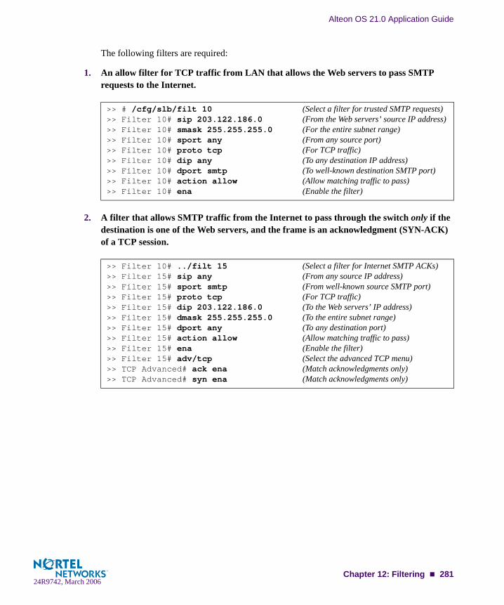
Alteon OS 21.0 Application Guide
The following filters are required:
1. An allow filter for TCP traffic from LAN that allows the Web servers to pass SMTP requests to the Internet.
2. A filter that allows SMTP traffic from the Internet to pass through the switch only if the destination is one of the Web servers, and the frame is an acknowledgment (SYN-ACK) of a TCP session.
>> # /cfg/slb/filt 10 (Select a filter for trusted SMTP requests)>> Filter 10# sip 203.122.186.0 (From the Web servers’ source IP address)>> Filter 10# smask 255.255.255.0 (For the entire subnet range)>> Filter 10# sport any (From any source port)>> Filter 10# proto tcp (For TCP traffic)>> Filter 10# dip any (To any destination IP address)>> Filter 10# dport smtp (To well-known destination SMTP port)>> Filter 10# action allow (Allow matching traffic to pass)>> Filter 10# ena (Enable the filter)
>> Filter 10# ../filt 15 (Select a filter for Internet SMTP ACKs)>> Filter 15# sip any (From any source IP address)>> Filter 15# sport smtp (From well-known source SMTP port)>> Filter 15# proto tcp (For TCP traffic)>> Filter 15# dip 203.122.186.0 (To the Web servers’ IP address)>> Filter 15# dmask 255.255.255.0 (To the entire subnet range)>> Filter 15# dport any (To any destination port)>> Filter 15# action allow (Allow matching traffic to pass)>> Filter 15# ena (Enable the filter)>> Filter 15# adv/tcp (Select the advanced TCP menu)>> TCP Advanced# ack ena (Match acknowledgments only)>> TCP Advanced# syn ena (Match acknowledgments only)
Chapter 12: Filtering 28124R9742, March 2006

Alteon OS 21.0 Application Guide
3. A filter that allows SMTP traffic from the Internet to pass through the switch only if the destination is one of the Web servers, and the frame is an acknowledgment (ACK-PSH) of a TCP session.
4. A filter that allows trusted HTTP traffic from the Internet to pass through the switch to the Web servers.
5. A filter that allows HTTP responses from the Web servers to pass through the switch to the Internet.
>> Filter 15# ../filt 16 (Select a filter for Internet SMTP ACKs)>> Filter 16# sip any (From any source IP address)>> Filter 16# sport smtp (From well-known source SMTP port)>> Filter 16# proto tcp (For TCP traffic)>> Filter 16# dip 203.122.186.0 (To the Web servers’ IP address)>> Filter 16# dmask 255.255.255.0 (To the entire subnet range)>> Filter 16# dport any (To any destination port)>> Filter 16# action allow (Allow matching traffic to pass)>> Filter 16# ena (Enable the filter)>> Filter 16# adv/tcp (Select the advanced TCP menu)>> TCP Advanced# ack ena (Match acknowledgments only)>> TCP Advanced# psh ena (Match acknowledgments only)
>> Filter 16 Advanced# /cfg/slb/filt 17(Select a filter for incoming HTTP traffic)>> Filter 17# sip any (From any source IP address)>> Filter 17# sport http (From well-known source HTTP port)>> Filter 17# proto tcp (For TCP traffic)>> Filter 17# dip 203.122.186.0 (To the Web servers’ IP address)>> Filter 17# dmask 255.255.255.0 (To the entire subnet range)>> Filter 17# dport http (To well-known destination HTTP port)>> Filter 17# action allow (Allow matching traffic to pass)>> Filter 17# ena (Enable the filter)
>> Filter 17# ../filt 18 (Select a filter for outgoing HTTP traffic)>> Filter 18# sip 203.122.186.0 (From the Web servers’ source IP address)>> Filter 18# smask 255.255.255.0 (From the entire subnet range)>> Filter 18# sport http (From well-known source HTTP port)>> Filter 18# proto tcp (For TCP traffic)>> Filter 18# dip any (To any destination IP address)>> Filter 18# dport http (To well-known destination HTTP port)>> Filter 18# action allow (Allow matching traffic to pass)>> Filter 18# ena (Enable the filter)
282 Chapter 12: Filtering24R9742, March 2006

Alteon OS 21.0 Application Guide
6. A default filter is required to deny all other traffic.
7. Apply the filters to the appropriate switch ports.
>> Filter 18# ../filt 1024 (Select a default filter)>> Filter 1024# sip any (From any source IP address)>> Filter 1024# dip any (To any destination IP address)>> Filter 1024# action deny (Block matching traffic)>> Filter 1024# name deny matching traffic (Provide a descriptive name for the filter)>> Filter 1024# ena (Enable the filter)
>> Filter 1024# ../port EXT1 (Select the Internet-side port)>> SLB port EXT1# add 15 (Add the SMTP ACK filter to the port)>> SLB port EXT1# add 16 (Add the incoming HTTP filter)>> SLB port EXT1# add 17 (Add the incoming HTTP filter)>> SLB port EXT1# add 1024 (Add the default filter to the port)>> SLB port EXT1# filt ena (Enable filtering on the port)>> SLB port EXT1# ../port 2 (Select the first Web server port)>> SLB port INT5# add 10 (Add the outgoing SMTP filter to the port)>> SLB port INT5# add 18 (Add the outgoing HTTP filter to the port)>> SLB port INT5# add 1024 (Add the default filter to the port)>> SLB port INT5# filt ena (Enable filtering on the port)>> SLB port INT5# ../port 3 (Select the other Web server port)>> SLB port INT6# add 10 (Add the outgoing SMTP filter to the port)>> SLB port INT6# add 18 (Add the outgoing HTTP filter to the port)>> SLB port INT6# add 1024 (Add the default filter to the port)>> SLB port INT6# filt ena (Enable filtering on the port)>> SLB port INT6# apply (Apply the configuration changes)>> SLB port INT6# save (Save the configuration changes)
Chapter 12: Filtering 28324R9742, March 2006

Alteon OS 21.0 Application Guide
Matching ICMP Message TypesInternet Control Message Protocol (ICMP) is used for reporting TCP/IP processing errors. There are numerous types of ICMP messages, as shown in Table 12-5. Although ICMP packets can be filtered using the proto icmp option, by default, the switch ignores the ICMP mes-sage type when matching a packet to a filter. To perform filtering based on specific ICMP mes-sage types, ICMP message type filtering must be enabled.
Alteon OS software supports filtering on the following ICMP message types:
Table 12-5 ICMP Message Types
Type # Message Type Description
0 echorep ICMP echo reply
3 destun ICMP destination unreachable
4 quench ICMP source quench
5 redir ICMP redirect
8 echoreq ICMP echo request
9 rtradv ICMP router advertisement
10 rtrsol ICMP router solicitation
11 timex ICMP time exceeded
12 param ICMP parameter problem
13 timereq ICMP timestamp request
14 timerep ICMP timestamp reply
15 inforeq ICMP information request
16 inforep ICMP information reply
17 maskreq ICMP address mask request
18 maskrep ICMP address mask reply
284 Chapter 12: Filtering24R9742, March 2006

Alteon OS 21.0 Application Guide
The command to enable or disable ICMP message type filtering is entered from the Advanced Filtering menu as follows:
For any given filter, only one ICMP message type can be set at any one time. The any option disables ICMP message type filtering. The list option displays a list of the available ICMP message types that can be entered.
NOTE – ICMP message type filters must be cache-disabled. Exercise caution when applying cache-enabled and cache-disabled filters to the same switch port. For more information, see “Cache-Enabled versus Cache-Disabled Filters” on page 259.
>> # /cfg/slb/filt <filter number>/adv>> Filter 1 Advanced# icmp <message type|number|any|list>
Chapter 12: Filtering 28524R9742, March 2006

Alteon OS 21.0 Application Guide
286 Chapter 12: Filtering24R9742, March 2006

CHAPTER 13Application Redirection
Application Redirection improves network bandwidth and provides unique network solutions. Filters can be created to redirect traffic to cache and application servers improving speed of access to repeated client access to common Web or application content and free valuable net-work bandwidth.
The following topics are discussed in this chapter:
“Overview” on page 288. Application redirection helps reduce the traffic congestion dur-ing peak loads by accessing locally cached information. This section also discusses how performance is improved by balancing cached requests across multiple servers.
“Cache Redirection Configuration Example” on page 290. This section provides a step-by-step procedure on how to intercept all Internet bound HTTP requests (on default TCP port 80) and redirect them to the cache servers.
“IP Proxy Addresses for NAT” on page 295. This section discusses the benefits of trans-parent proxies when used with application redirection.
“Excluding Noncacheable Sites” on page 297. This section describes how to filter out applications that keep real-time session information from being redirected to cache serv-ers.
24R9742, March 2006287

Alteon OS 21.0 Application Guide
OverviewMost of the information downloaded from the Internet is not unique, as clients will often access the Web page many times for additional information or to explore other links. Duplicate information also gets requested as the components that make up Internet data at a particular Web site (pictures, buttons, frames, text, and so on) are reloaded from page to page. When you consider this scenario in the context of many clients, it becomes apparent that redundant requests can consume a considerable amount of your available bandwidth to the Internet.
Application redirection can help reduce the traffic congestion during peak loads. When Appli-cation redirection filters are properly configured for the Alteon OS-powered switch, outbound client requests for Internet data are intercepted and redirected to a group of application or cache servers on your network. The servers duplicate and store inbound Internet data that has been requested by your clients. If the servers recognize a client’s outbound request as one that can be filled with cached information, the servers supply the information rather than send the request across the Internet.
In addition to increasing the efficiency of your network, accessing locally cached information can be much faster than requesting the same information across the Internet.
Cache Redirection EnvironmentConsider a network where client HTTP requests begin to regularly overload the Internet router.
Figure 13-1 Traditional Network Without Cache Redirection
Clients
Internet
Router
Client Switch
Client Switch
CongestionTargets Router
288 Chapter 13: Application Redirection24R9742, March 2006

Alteon OS 21.0 Application Guide
The network needs a solution that addresses the following key concerns:
The solution must be readily scalable
The administrator should not need to reconfigure all the clients’ browsers to use proxy servers.
Figure 13-2 Network with Cache Redirection
If you have more clients than switch ports, then connect the clients to a layer 2 switch.
Adding a GbE Switch Module with Layer 4 software addresses these issues:
Cache servers can be added or removed dynamically without interrupting services.
Performance is improved by balancing the cached request load across multiple servers. More servers can be added at any time to increase processing power.
The proxy is transparent to the client.
Frames that are not associated with HTTP requests are normally passed to the router.
Additional Application Redirection OptionsApplication redirection can be used in combination with other Layer 4 options, such as load balancing metrics, health checks, real server group backups, and more. See “Additional Server Load Balancing Options” on page 182 for details.
BladeCenterBladeCenter
InternetInternet
GbESM
Chapter 13: Application Redirection 28924R9742, March 2006
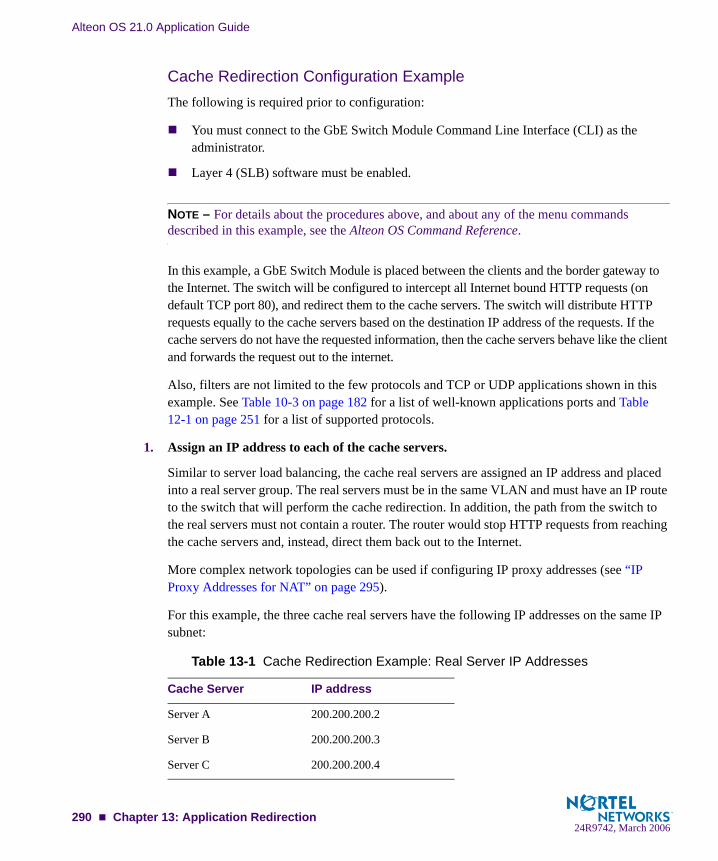
Alteon OS 21.0 Application Guide
Cache Redirection Configuration ExampleThe following is required prior to configuration:
You must connect to the GbE Switch Module Command Line Interface (CLI) as the administrator.
Layer 4 (SLB) software must be enabled.
NOTE – For details about the procedures above, and about any of the menu commands described in this example, see the Alteon OS Command Reference.
In this example, a GbE Switch Module is placed between the clients and the border gateway to the Internet. The switch will be configured to intercept all Internet bound HTTP requests (on default TCP port 80), and redirect them to the cache servers. The switch will distribute HTTP requests equally to the cache servers based on the destination IP address of the requests. If the cache servers do not have the requested information, then the cache servers behave like the client and forwards the request out to the internet.
Also, filters are not limited to the few protocols and TCP or UDP applications shown in this example. See Table 10-3 on page 182 for a list of well-known applications ports and Table 12-1 on page 251 for a list of supported protocols.
1. Assign an IP address to each of the cache servers.
Similar to server load balancing, the cache real servers are assigned an IP address and placed into a real server group. The real servers must be in the same VLAN and must have an IP route to the switch that will perform the cache redirection. In addition, the path from the switch to the real servers must not contain a router. The router would stop HTTP requests from reaching the cache servers and, instead, direct them back out to the Internet.
More complex network topologies can be used if configuring IP proxy addresses (see “IP Proxy Addresses for NAT” on page 295).
For this example, the three cache real servers have the following IP addresses on the same IP subnet:
Table 13-1 Cache Redirection Example: Real Server IP Addresses
Cache Server IP address
Server A 200.200.200.2
Server B 200.200.200.3
Server C 200.200.200.4
290 Chapter 13: Application Redirection24R9742, March 2006

Alteon OS 21.0 Application Guide
2. Install transparent cache software on all three cache servers.
3. Define an IP interface on the switch.
The switch must have an IP interface on the same subnet as the three cache servers because, by default, the switch only remaps destination MAC addresses.
To configure an IP interface for this example, enter this command from the CLI:
NOTE – The IP interface and the real servers must be in the same subnet. This example assumes that all ports and IP interfaces use default VLAN 1, requiring no special VLAN con-figuration for the ports or IP interface.
4. Define each real server on the switch.
For each cache real server, you must assign a real server number, specify its actual IP address, and enable the real server. For example:
5. Define a real server group.
This places the three cache real servers into one service group:
>> # /cfg/l3/if 1 (Select IP interface 1)>> IP Interface 1# addr 200.200.200.100 (Assign IP address for the interface)>> IP Interface 1# ena (Enable IP interface 1)
>> ip# /cfg/slb/real 1 (Server A is real server 1)>> Real server 1# rip 200.200.200.2 (Assign Server A IP address)>> Real server 1# ena (Enable real server 1)>> Real server 1# ../real 2 (Server B is real server 2)>> Real server 2# rip 200.200.200.3 (Assign Server B IP address)>> Real server 2# ena (Enable real server 2)>> Real server 2# ../real 3 (Server C is real server 3)>> Real server 3# rip 200.200.200.4 (Assign Server C IP address)>> Real server 3# ena (Enable real server 3)
>> Real server 3# ../group 1 (Select real server group 1)>> Real server group 1# add 1 (Add real server 1 to group 1)>> Real server group 1# add 2 (Add real server 2 to group 1)>> Real server group 1# add 3 (Add real server 3 to group 1)
Chapter 13: Application Redirection 29124R9742, March 2006

Alteon OS 21.0 Application Guide
6. Set the real server group metric to minmisses.
This setting helps minimize cache misses in the event real servers fail or are taken out of ser-vice:
7. Verify that server processing is disabled on the ports supporting application redirection.
NOTE – Do not use the “server” setting on a port with Application Redirection enabled. Server processing is used only with server load balancing. To disable server processing on the port, use the commands on the /cfg/slb/port menu, as described in the Alteon OS Command Reference.
8. Create a filter that will intercept and redirect all client HTTP requests.
The filter must be able to intercept all TCP traffic for the HTTP destination port and must redi-rect it to the proper port on the real server group:
The rport(redirection) parameter must be configured whenever TCP/UDP protocol traffic is redirected. The rport parameter defines the real server TCP or UDP port to which redirected traffic will be sent. The port defined by the rport parameter is used when performing Layer 4 health checks of TCP services.
Also, if NAT and proxy addresses are used on the switch (see Step 3 on page 291), the rport parameter must be configured for all application redirection filters. Take care to use the proper port designation with rport: if the transparent proxy operation resides on the host, the well-known port 80 (or HTTP) is probably required. If the transparent proxy occurs on the switch, make sure to use the service port required by the specific software package.
See “IP Proxy Addresses for NAT” on page 295 for more information on IP proxy addresses.
>> Real server group 1# metric minmisses (Metric for minimum cache misses.)
>> SLB port 2# /cfg/slb/filt 2 (Select the menu for Filter 2)>> Filter 2# sip any (From any source IP addresses)>> Filter 2# dip any (To any destination IP addresses)>> Filter 2# proto tcp (For TCP protocol traffic)>> Filter 2# sport any (From any source port)>> Filter 2# dport http (To an HTTP destination port)>> Filter 2# action redir (Set the action for redirection)>> Filter 2# rport http (Set the redirection port)>> Filter 2# group 1 (Select real server group 1)>> Filter 2# ena (Enable the filter)
292 Chapter 13: Application Redirection24R9742, March 2006
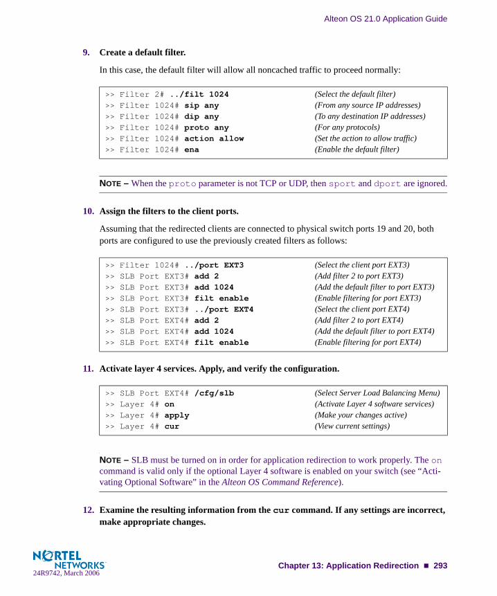
Alteon OS 21.0 Application Guide
9. Create a default filter.
In this case, the default filter will allow all noncached traffic to proceed normally:
NOTE – When the proto parameter is not TCP or UDP, then sport and dport are ignored.
10. Assign the filters to the client ports.
Assuming that the redirected clients are connected to physical switch ports 19 and 20, both ports are configured to use the previously created filters as follows:
11. Activate layer 4 services. Apply, and verify the configuration.
NOTE – SLB must be turned on in order for application redirection to work properly. The on command is valid only if the optional Layer 4 software is enabled on your switch (see “Acti-vating Optional Software” in the Alteon OS Command Reference).
12. Examine the resulting information from the cur command. If any settings are incorrect, make appropriate changes.
>> Filter 2# ../filt 1024 (Select the default filter)>> Filter 1024# sip any (From any source IP addresses)>> Filter 1024# dip any (To any destination IP addresses)>> Filter 1024# proto any (For any protocols)>> Filter 1024# action allow (Set the action to allow traffic)>> Filter 1024# ena (Enable the default filter)
>> Filter 1024# ../port EXT3 (Select the client port EXT3)>> SLB Port EXT3# add 2 (Add filter 2 to port EXT3)>> SLB Port EXT3# add 1024 (Add the default filter to port EXT3)>> SLB Port EXT3# filt enable (Enable filtering for port EXT3)>> SLB Port EXT3# ../port EXT4 (Select the client port EXT4)>> SLB Port EXT4# add 2 (Add filter 2 to port EXT4)>> SLB Port EXT4# add 1024 (Add the default filter to port EXT4)>> SLB Port EXT4# filt enable (Enable filtering for port EXT4)
>> SLB Port EXT4# /cfg/slb (Select Server Load Balancing Menu)>> Layer 4# on (Activate Layer 4 software services)>> Layer 4# apply (Make your changes active)>> Layer 4# cur (View current settings)
Chapter 13: Application Redirection 29324R9742, March 2006

Alteon OS 21.0 Application Guide
13. Save your new configuration changes.
14. Check the SLB information.
Check that all SLB parameters are working according to expectation. If necessary, make any appropriate configuration changes and then check the information again.
NOTE – Changes to filters on a given port only effect new sessions. To make filter changes take effect immediately, clear the session binding table for the port (see the /oper/slb/clear command in the Alteon OS Command Reference).
Delayed Binding for Cache RedirectionTo configure delayed binding on your switch for cache redirection only, use the following command:
For more conceptual information on delayed binding, see “Delayed Binding” on page 200.
>> Layer 4# save (Save for restore after reboot)
>> Layer 4# /info/slb (View SLB information)
>> # /cfg/slb/filt <filter number>/adv/urlp ena
294 Chapter 13: Application Redirection24R9742, March 2006

Alteon OS 21.0 Application Guide
IP Proxy Addresses for NATTransparent proxies provide the benefits listed below when used with application redirection. Application redirection is automatically enabled when a filter with the redir action is applied on a port.
With proxy IP addresses configured on ports that use redirection filters, the switch can redirect client requests to servers located on any subnet.
The switch can perform transparent substitution for all source and destination addresses, including destination port remapping. This provides support for comprehensive, fully-transparent proxies. No additional client configuration is needed.
The following procedure can be used for configuring proxy IP addresses:
1. Configure proxy IP addresses and enable proxy for the client ports.
Each of the ports using redirection filters require proxy IP addresses. If Virtual Matrix Archi-tecture (VMA) is enabled, you must configure both proxy IP addresses. If VMA is disabled, only the client port with filters require proxy IP addresses.
In this example, VMA is enabled, so configure two proxy IP addresses:
2. Configure the application redirection filters.
>> SLB port EXT3# /cfg/slb/pip (Select proxy IP address menu)>> Proxy IP Address# pip1 200.200.200.68 (Set proxy IP address)>> Proxy IP Address# pip2 200.200.200.69 (Set proxy IP address)>> Proxy IP Address# ../port EXT1 (Select port EXT1)>> SLB port EXT1# proxy ena (Enable proxy port EXT1)>> SLB port EXT1# ../port EXT2 (Select port EXT2)>> SLB port EXT2# proxy ena (Enable proxy port EXT2)>> SLB port EXT2# ../port EXT3 (Select port EXT3)>> SLB port EXT3# proxy ena (Enable proxy port EXT3)>> SLB port EXT3# ../port EXT4 (Select port EXT4)>> SLB port EXT4# proxy ena (Enable proxy port EXT4)
Chapter 13: Application Redirection 29524R9742, March 2006

Alteon OS 21.0 Application Guide
Once proxy IP addresses are established, configure each application redirection filter (Filter 2 in our example) with the real server TCP or UDP port to which redirected traffic will be sent. In this case, the requests are mapped to a different destination port (8080). You must also enable proxies on the real servers:
NOTE – This configuration is not limited to HTTP (Web) service. Other TCP/IP services can be configured in a similar fashion. For example, if this had been a DNS redirect, rport would be sent to well-known port 53 (or the service port you want to remap to). For a list of other well-known services and ports, see the Table 10-3 on page 182.
3. Apply and save your changes.
4. Check server statistics to verify that traffic has been redirected based on filtering criteria:
>> # /cfg/slb/filt 2 (Select the menu for Filter 2)>> Filter 2# rport 8080 (Set proxy redirection port)>> Filter 2# ../real 1/proxy enable (Enable proxy on real servers)>> Real server 1# ../real 2/proxy enable (Enable proxy on real servers)>> Real server 2# ../real 3/proxy enable (Enable proxy on real servers)
>> # /info/slb/group <group number>/filt <filter number>
296 Chapter 13: Application Redirection24R9742, March 2006

Alteon OS 21.0 Application Guide
Excluding Noncacheable SitesSome sites provide content that is not well suited for redirection to cache servers. Such sites might provide browser-based games or applications that keep real-time session information or authenticate by client IP address.
To prevent such sites from being redirected to cache servers, create a filter that allows this spe-cific traffic to pass normally through the switch. This filter must have a higher precedence (a lower filter number) than the application redirection filter.
For example, if you want to prevent a popular Web-based game site on subnet 200.10.10.* from being redirected, you could add the following to the previous example configuration:
>> # /cfg/slb/filt 1 (Select the menu for filter 1)>> Filter 1# dip 200.10.10.0 (To the site’s destination IP address)>> Filter 1# dmask 255.255.255.0 (For entire subnet range)>> Filter 1# sip any (From any source IP address)>> Filter 1# proto tcp (For TCP traffic)>> Filter 1# dport http (To an HTTP destination port)>> Filter 1# sport any (From any source port)>> Filter 1# action allow (Allow matching traffic to pass)>> Filter 1# ena (Enable the filter)>> Filter 1# ../port EXT3 (Select SLB port EXT3)>> SLB port EXT3# add 1 (Add the filter to port EXT3)>> SLB port EXT3# ../port EXT4 (Select SLB port EXT4)>> SLB port EXT4# add 1 (Add the filter to port EXT4)>> SLB port EXT4# apply (Apply configuration changes)>> SLB port EXT4# save (Save configuration changes)
Chapter 13: Application Redirection 29724R9742, March 2006

Alteon OS 21.0 Application Guide
298 Chapter 13: Application Redirection24R9742, March 2006

CHAPTER 14Health Checking
Health checking allows you to verify content accessibility in large Web sites. As content grows and information is distributed across different server farms, flexible, customizable content health checks are critical to ensure end-to-end availability.
The following Alteon OS health-checking topics are described in this chapter.
“Real Server Health Checks” on page 301. This section explains the switch’s default health check, which checks the status of each service on each real server every two seconds.
“Link Health Checks” on page 302. This section describes how to perform Layer 1 health checking on an Intrusion Detection Server (IDS).
“TCP Health Checks” on page 303. TCP health checks help verify the TCP applications that cannot be scripted.
“ICMP Health Checks” on page 303. This section explains how ICMP health checks are used for UDP services.
“Script-Based Health Checks” on page 304. This section describes how to configure the switch to send a series of health-check requests to real servers or real server groups and monitor the responses.
Application-based health checks:
“HTTP Health Checks” on page 309. This section provides examples of HTTP-based health checks using hostnames.
“UDP-Based DNS Health Checks” on page 311. This section explains the functional-ity of the DNS Health Checks using UDP packets.
“FTP Server Health Checks” on page 312. This section describes how the File Trans-fer Protocol (FTP) server is used to perform health checks and explains how to con-figure the switch to perform FTP health checks.
“POP3 Server Health Checks” on page 313. This section explains how to use Post Office Protocol Version 3 (POP3) mail server to perform health checks between a cli-ent system and a mail server and how to configure the switch for POP3 health checks.
24R9742, March 2006299

Alteon OS 21.0 Application Guide
“SMTP Server Health Checks” on page 314. This section explains how to use Simple Mail Transfer Protocol (SMTP) mail server to perform health checks between a client system and a mail server and how to configure the switch for SMTP health checks.
“IMAP Server Health Checks” on page 315. This section describes how the mail server Internet Message Access Protocol (IMAP) protocol is used to perform health checks between a client system and a mail server.
“NNTP Server Health Checks” on page 316. This section explains how to use Net-work News Transfer Protocol (NNTP) server to perform health checks between a cli-ent system and a mail server and how to configure the switch for NNTP health checks
“RADIUS Server Health Checks” on page 317. This section explains how the RADIUS protocol is used to authenticate dial-up users to Remote Access Servers (RASs).
“HTTPS/SSL Server Health Checks” on page 318. This section explains how the switch queries the health of the SSL servers by sending an SSL client “Hello” packet and then verifies the contents of the server’s “Hello” response.
“WAP Gateway Health Checks” on page 318. This section discusses how the switch provides a connectionless WSP health check for WAP gateways.
“LDAP Health Checks” on page 321. This section describes how to configure the switch to perform Lightweight Directory Access Protocol (LDAP) health checks for the switch to determine whether or not the LDAP server is running.
“Windows Terminal Server Health Checks” on page 322. This section describes how to configure the switch to perform Windows Terminal Server health checks.
“ARP Health Checks” on page 323. This section describes how to perform health checks on Intrusion Detection Servers (IDS) that do not have full TCP/IP stack support.
“Failure Types” on page 324. This section explains the service failed and server failed states.
300 Chapter 14: Health Checking24R9742, March 2006
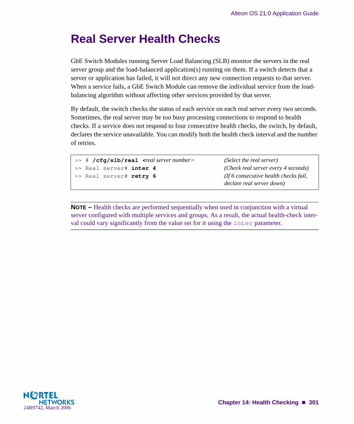
Alteon OS 21.0 Application Guide
Real Server Health ChecksGbE Switch Modules running Server Load Balancing (SLB) monitor the servers in the real server group and the load-balanced application(s) running on them. If a switch detects that a server or application has failed, it will not direct any new connection requests to that server. When a service fails, a GbE Switch Module can remove the individual service from the load-balancing algorithm without affecting other services provided by that server.
By default, the switch checks the status of each service on each real server every two seconds. Sometimes, the real server may be too busy processing connections to respond to health checks. If a service does not respond to four consecutive health checks, the switch, by default, declares the service unavailable. You can modify both the health check interval and the number of retries.
NOTE – Health checks are performed sequentially when used in conjunction with a virtual server configured with multiple services and groups. As a result, the actual health-check inter-val could vary significantly from the value set for it using the inter parameter.
>> # /cfg/slb/real <real server number> (Select the real server)>> Real server# inter 4 (Check real server every 4 seconds)>> Real server# retry 6 (If 6 consecutive health checks fail,
declare real server down)
Chapter 14: Health Checking 30124R9742, March 2006

Alteon OS 21.0 Application Guide
Link Health ChecksLink health checks are performed at the Layer 1 (physical) level, and are used on servers that do not respond to any other type of health check. Intrusion Detection Servers (IDSs) fall into this category.
The server is considered to be up when the link (connection) is present, and down when the link is absent. Many IDSs have two physical interfaces. One is used to detect intrusions, and the other is used to generate logging. The first interface detects intrusions but it does not have TCP/IP stack. So it is not possible to perform any health check other than Layer 1 health checking on the IDS. As long as the physical link between the switch and the IDS is up, it indi-cates the IDS is alive.
To perform this health check, a link option has been added to the real server group health com-mand. The real server number is used to determine which port the server is connected to. For example, real server 1 is assumed to be connected to port 1. The valid IDS real server numbers are from 1 to 26 when health check is in use.
Configuring the Switch for Link Health ChecksConfigure the switch to verify if the IDS server is alive by performing the following tasks:
1. Select the health check menu for real server group 1.
2. Set the health check type to link for real server group 1.
3. Apply and save your configuration.
>> # /cfg/slb/group 1
>> # Real server group 1# healthCurrent health check type: tcpEnter health check type: link
>> # Real server group 1# apply>> # Real server group 1# save
302 Chapter 14: Health Checking24R9742, March 2006

Alteon OS 21.0 Application Guide
TCP Health ChecksTCP health checks are useful in verifying user-specific TCP applications that cannot be scripted.
Session switches monitor the health of servers and applications by sending Layer 4 connection requests (TCP SYN packets) for each load-balanced TCP service to each server in the server group on a regular basis. The rate at which these connection requests are sent is a user-config-urable parameter. These connection requests identify both failed servers and failed services on a healthy server. When a connection request succeeds, the session switch quickly closes the connection by sending a TCP FIN (finished) packet.
NOTE – TCP health check is a default health check after you have configured the switch for a particular service.
ICMP Health ChecksConfigure the switch with ICMP health check to verify if the real server is alive. The Layer 3 echo - echo reply health check is used for UDP services or when ICMP health checks are configured.
1. Select the health check menu for group 1.
2. Set the health check type to ICMP for group 1.
3. Apply and save your configuration.
>> # /cfg/slb/group 1
>> # Real server group 1# health icmp
>> # Real server group 1# apply
Chapter 14: Health Checking 30324R9742, March 2006

Alteon OS 21.0 Application Guide
Script-Based Health ChecksThe “send/expect” script-based health checks dynamically verify application and content availability using scripts. These scripts execute a sequence of tests to verify application and content availability.
Configuring the Switch for Script-Based Health ChecksYou can configure the switch to send a series of health check requests to real servers or real server groups and monitor the responses. ASCII-based scripts can be used to verify application and content availability.
NOTE – Only TCP services can be health checked, since UDP protocols are usually not ASCII based.
The benefits of using script-based health checks are listed below:
Ability to send multiple commandsCheck for any return stringTest availability of different applicationsTest availability of multiple domains or Web sites
Alteon OS supports the following capacity for a single switch:
1024 bytes per script16 scripts per switchapproximately 10 to 15 health check statements (HTTP get and expect strings)
A simple command line interface controls the addition and deletion of ASCII commands to each script. New commands are added and removed from the end of the script. Commands exist to open a connection to a specific TCP port, send an ASCII request to the server, expect an ASCII string, and close a connection. The string configured with an expect command is searched for in each response packet. If it is not seen anywhere in any response packet before the real server health check interval expires, the server does not pass the expect step and fails the health check. A script can contain any number of these commands, up to the allowable number of characters that a script supports.
NOTE – Health check scripts can only be set up via the command line interface, but once entered, can be assigned as the health-check method using SNMP or the Browser-Based Inter-face (BBI).
304 Chapter 14: Health Checking24R9742, March 2006

Alteon OS 21.0 Application Guide
Script FormatThe general format for health-check scripts is shown below:
NOTE – If you are doing HTTP 1.1 pipelining, you need to individually open and close each response in the script.
Each script should start with the command open port <protocol port number>. The next line can be either a send or expect.
The first word is the method. This is usually get; however, HTTP supports several other commands, including put and head. The second word indicates the content desired, or request-URI, and the third word represents the version of the protocol used by the client.
If you supplied HTTP/1.1 for the protocol version, you would also have to add in the fol-lowing line: Host: www.hostname.com
Example: GET /index.html HTTP/1.1 (press Enter key)Host: www.hostname.com (press Enter key twice)
This is known as a host header. It is important to include because most Web sites now require it for proper processing. Host headers were optional in HTTP/1.0 but are required when you use HTTP/1.1+.
In order to tell the application server you have finished entering header information, a blank line of input is needed after all headers. At this point, the URL will be processed and the results returned to you.
NOTE – If you make an error, enter rem to remove the last typed script line entered. If you need to remove more than one line, enter rem for each line that needs to be removed.
The switch provides the “\” prompt, which is one enter key stroke. When using the send command, note what happens when you type the send command with the command string. When you type send, press enter and allow the switch to format the command string (that is, \ versus \\).
open application_port (e.g., 80 for HTTP, 23 for Telnet, etc.)send request1expect response1send request2expect response2send request3expect response3close
Chapter 14: Health Checking 30524R9742, March 2006

Alteon OS 21.0 Application Guide
Scripting GuidelinesUse generic result codes that are standard and defined by the RFC, as applicable. This helps ensure that if the server software changes, the servers won't start failing unexpect-edly.
Search only for the smallest and most concise piece of information possible. Each script cannot exceed 1K in size, so use the space wisely.
Avoid tasks that may take a long time to perform or the health check will fail. For exam-ple, avoid tasks that exceed the interval for load balancing.
Script Configuration Examples
Script Example 1: A Basic Health CheckConfigure the switch to check a series of Web pages (HTML or dynamic CGI scripts) before it declares a real server is available to receive requests.
NOTE – If you are using the CLI to create a health check script, you must use quotes (“) to indicate the beginning and end of each command string.
NOTE – When you are using the command line interface to enter the send string as an argu-ment to the send command, you must type two “\”s before an “n” or “r.” If you are instead prompted for the line, that is, the text string is entered after hitting <return>, then only one “\” is needed before the “n” or “r.”
/cfg/slb/group x/health script1/content none/cfg/slb/advhc/script1
open 80send "GET /index.html HTTP/1.1\\r\\nHOST:www.hostname.com\\r\\n\\r\\n"expect "HTTP/1.1 200"closeopen 80send "GET /script.cgi HTTP/1.1\\r\\nHOST:www.hostname.com\\r\\n\\r\\n"expect "HTTP/1.1 200"closeopen 443…close
306 Chapter 14: Health Checking24R9742, March 2006

Alteon OS 21.0 Application Guide
Verifying Script-Based Health ChecksIf a script fails, the expect line in the script that is not succeeding is displayed under the /info/slb/real <real server number> command:
The server is not responding to the get with the expect string.
When the script succeeds in determining the health of a real server, the following information is displayed:
>> # /info/slb/real 1 1: 205.178.13.225, 00:00:00:00:00:00, vlan 1, port 0, health 4, FAILED real ports: script 1, DOWN, current send GET / HTTP/1.0\r\n\r\n expect HTTP/1.0 200
>> # /info/slb/real 1 1: 205.178.13.223, 00:00:5e:00:01:24, vlan 1, port INT2, health 4, up real ports: script 1, up, current
Chapter 14: Health Checking 30724R9742, March 2006

Alteon OS 21.0 Application Guide
Application-Specific Health ChecksApplication-specific health checks include the following applications:
“HTTP Health Checks” on page 309“UDP-Based DNS Health Checks” on page 311“FTP Server Health Checks” on page 312“POP3 Server Health Checks” on page 313“SMTP Server Health Checks” on page 314“IMAP Server Health Checks” on page 315“NNTP Server Health Checks” on page 316“RADIUS Server Health Checks” on page 317“HTTPS/SSL Server Health Checks” on page 318 “WAP Gateway Health Checks” on page 318
“WSP Content Health Checks” on page 319
“WTLS Health Checks” on page 320
“LDAP Health Checks” on page 321
308 Chapter 14: Health Checking24R9742, March 2006

Alteon OS 21.0 Application Guide
HTTP Health ChecksHTTP-based health checks can include the hostname for HOST: headers. The HOST: header and health check URL are constructed from the following components:
If the HOST: header is required, an HTTP/1.1 GET will occur. Otherwise, an HTTP/1.0 GET will occur. HTTP health check is successful if you get a return code of 200.
Example 1:
hname = everestdname = websystems.comcontent = index.html
Health check is performed using:
GET /index.html HTTP/1.1Host: everest.websystems.com
NOTE – If the content is not specified, the health check will revert back to TCP on the port that is being load balanced.
Example 2:
hname = (none)dname = raleighduram.cityguru.comcontent = /page/gen/?_template=websystems
Health check is performed using:
GET /page/gen/?_template=websystems HTTP/1.1Host: raleighduram.cityguru.com
Example 3:
hname = (none)dname = jansuscontent = index.html
Item Option Configured Under Max. Length
Virtual server hostname hname /cfg/slb/virt/service 9 characters
Domain name dname /cfg/slb/virt 35 characters
Server group health check field content /cfg/slb/group 34 characters
Chapter 14: Health Checking 30924R9742, March 2006

Alteon OS 21.0 Application Guide
Health check is performed using:
GET /index.html HTTP/1.1Host: jansus
Example 4:
hname = (none)dname = (none)content = index.html
Health check is performed using:
GET /index.html HTTP/1.0 (since no HTTP HOST: header is required)
Example 5:
hname = (none)dname = (none)content = //everest/index.html
Health check is performed using:
GET /index.html HTTP/1.1Host: everest
Configuring the Switch for HTTP Health ChecksPerform the following on the switch to configure the switch for HTTP health checks:
1. Select the real server group.
2. Set the health check type to FTP for the real server group.
3. Configure the health check content.
4. Apply and save your configuration.
>> # /cfg/slb/group 1 (Select a real server group)
>> # /cfg/slb/group 1/health http
>> # /cfg/slb/group 1/content <filename>
>> # Real server group 1# apply>> # Real server group 1# save
310 Chapter 14: Health Checking24R9742, March 2006

Alteon OS 21.0 Application Guide
UDP-Based DNS Health Checks Alteon OS supports UDP-based health checks along with TCP health checks, and performs load-balancing based on TCP and UDP protocols.
DNS servers can be based on both TCP and UDP protocols. With UDP-based DNS health checks enabled, you can send TCP-based queries to one real server group and UDP-based que-ries to another real server group.
The health check may be performed by sending a UDP-based query (for example, for www.nortelnetworks.com), and watching for the server’s reply. The domain name to be que-ried may be modified by specifying the content command if you need to change the domain name.
Configuring the Switch for UDP-based Health ChecksConfigure the switch to verify if the DNS server is alive.
1. Select the real server group.
2. Set the health check type to UDP for the real server group.
3. Set the content to domain name.
4. Apply and save your configuration.
NOTE – If no host name is configured, the health check is performed by sending a UDP-based query from a dummy host and watching for the server’s reply. The reply, even though negative (for example, “Server not found” since the query is from a dummy host), serves the purpose of a health check, nonetheless.
>> # /cfg/slb/group 1
>> # Real server group 1# health udpdns
>> # Real server group 1# content <filename>|//<host><filename>|none
>> # Real server group 1# apply>> # Real server group 1# save
Chapter 14: Health Checking 31124R9742, March 2006

Alteon OS 21.0 Application Guide
FTP Server Health ChecksThe Internet File Transfer Protocol (FTP) provides facilities for transferring files to and from remote computer systems. Usually the user transferring a file needs authority to login and access files on the remote system. This protocol is documented in RFC 1123.
In normal Internet operation, the FTP server listens on the well-known port number 21 for con-trol connection requests. The client sends a control message which indicates the port number on which the client is prepared to accept an incoming data connection request.
When a transfer is being set up, it is always initiated by the client. However, either the client or the server may be the sender of data. Along with transferring user requested files, the data transfer mechanism is also used for transferring directory listings from server to client.
NOTE – To configure the switch for FTP health checks, the FTP server must accept anony-mous user.
Configuring the Switch for FTP Health ChecksCreate any file name from an FTP server under FTP server directory, for example, .txt, .exe, .bin and so forth.
To configure the switch for FTP health checks:
1. Select the real server group.
2. Set the health check type to FTP for the real server group.
3. Configure the health check content.
4. Apply and save your configuration.
>> # /cfg/slb/group 1 (Select a real server group)
>> # /cfg/slb/group 1/health ftp
>> # /cfg/slb/group 1/content <filename>
>> # Real server group 1# apply>> # Real server group 1# save
312 Chapter 14: Health Checking24R9742, March 2006

Alteon OS 21.0 Application Guide
POP3 Server Health ChecksThe Post Office Protocol - Version 3 (POP3) is intended to permit a workstation to dynami-cally access a maildrop on a server host. The POP3 protocol is used to allow a workstation to retrieve mail that the server is holding for it. This protocol is documented in RFC 1939.
When the user on a client host wants to enter a message into the transport system, it establishes an SMTP connection to its relay host and sends all mail to it.
Initially, the server host starts the POP3 service by listening on TCP port 110. When a client host wants to make use of the service, it establishes a TCP connection with the server host.
Configuring the Switch for POP3 Health ChecksTo support health checking on the UNIX POP3 server, the network administrator must config-ure a username:password value in the switch, using the content option on the SLB real server group menu (/cfg/slb/group)
To configure the switch for POP3 health checks:
1. Select the real server group.
2. Set the health check type to POP3 for the real server group..
3. Configure the health check content.
4. Apply and save your configuration.
>> # /cfg/slb/group 1 (Select a real server group)
>> # /cfg/slb/group 1/health pop3
>> # /cfg/slb/group 1/content <username>:<password>
>> # Real server group 1# apply>> # Real server group 1# save
Chapter 14: Health Checking 31324R9742, March 2006

Alteon OS 21.0 Application Guide
SMTP Server Health ChecksSimple Mail Transfer Protocol is a protocol to transfer e-mail messages between servers reli-ably and efficiently. This protocol traditionally operates over TCP port 25 and is documented in RFC 821. Most e-mail systems that send mail over the Internet use SMTP to send messages from one server to another; the messages can then be retrieved with an e-mail client using either POP or IMAP.
Configuring the Switch for SMTP Health ChecksTo support SMTP health checking, the network administrator must configure a username:pass-word value in the switch, using the content option on the SLB real server group menu (/cfg/slb/group)
To configure the switch for SMTP health checks:
1. Select the health check menu for the real server group.
2. Set the health check type to SMTP for the real server group..
3. Configure the health check content.
4. Apply and save your configuration.
>> # /cfg/slb/group 1 (Select a real server group)
>> # /cfg/slb/group 1/health smtp
>> # /cfg/slb/group 1/content <username>
>> # Real server group 1# apply>> # Real server group 1# save
314 Chapter 14: Health Checking24R9742, March 2006
Alteon OS 21.0 Application Guide
IMAP Server Health ChecksInternet Message Access Protocol (IMAP) is a mail server protocol used between a client sys-tem and a mail server that allows a user to retrieve and manipulate mail messages. IMAP is not used for mail transfers between mail servers. IMAP servers listen to TCP port 143.
Configuring the Switch for IMAP Health CheckTo support IMAP health checking, the network administrator must configure a username:pass-word value in the switch, using the content option on the SLB Real Server Group Menu (/cfg/slb/group).
To configure the switch for IMAP health checks:
1. Select the health check menu for the real server group.
2. Set the health check type to IMAP for the real server group..
3. Configure the health check content.
The content option specifies the username:password value that the server tries to match in its user database. In addition to verifying the user name and password, the database may spec-ify the client(s) or port(s) the user is allowed to access.
4. Apply and save your configuration.
>> # /cfg/slb/group 1 (Select a real server group)
>> # /cfg/slb/group 1/health imap
>> # /cfg/slb/group 1/content <username>:<password>
>> # Real server group 1# apply>> # Real server group 1# save
Chapter 14: Health Checking 31524R9742, March 2006

Alteon OS 21.0 Application Guide
NNTP Server Health ChecksNet News Transfer Protocol (NNTP) is a TCP/IP protocol based upon text strings sent bidirec-tionally over 7 bit ASCII TCP channels, and listens to port 119. It is used to transfer articles between servers as well as to read and post articles. NNTP specifies a protocol for the distribu-tion, inquiry, retrieval, and posting of news articles using a reliable stream-based transmission of news among the ARPA-Internet community. NNTP is designed so that news articles are stored in a central database allowing a subscriber to select only those items he wishes to read.
NNTP is documented in RFC977. Articles are transmitted in the form specified by RFC1036.
Configuring the Switch for NNTP Health ChecksTo configure the switch for NNTP health checks:
1. Select the real server group.
2. Set the health check type to NNTP for the real server group.
3. Configure the health check content.
Create nntp directory from MS Windows Option Pack4.
4. Apply and save your configuration.
>> # /cfg/slb/group 1 (Select a real server group)
>> # /cfg/slb/group 1/health nntp
>> # /cfg/slb/group 1/content <nntp newsgroup name>
>> # Real server group 1# apply>> # Real server group 1# save
316 Chapter 14: Health Checking24R9742, March 2006
Alteon OS 21.0 Application Guide
RADIUS Server Health ChecksThe Remote Authentication Dial-In User Service (RADIUS) protocol is used to authenticate dial-up users to Remote Access Servers (RASs) and the client application they will use during the dial-up connection.
RADIUS Content Health Check Enhancements
Include the switch IP as the Network-attached storage (NAS) IP parameter in the RADIUS content health check
RADIUS health check using the configured real server port (rport)
Variable-length RADIUS secret password. Supports less than 16 octets and up to 32 octets
The secret value is a field of up to 32 alphanumeric characters used by the switch to encrypt a password during the RSA Message Digest Algorithm (MD5) and by the RADIUS server to decrypt the password during verification.
The content option specifies the username:password value that the server tries to match in its user database. In addition to verifying the user name and password, the data-base may specify the client(s) or port(s) the user is allowed to access.
NOTE – Network-attached storage (NAS) is hard disk storage that is set up with its own net-work address rather than being attached to the department computer that is serving applications to a network's workstation users. By removing storage access and its management from the department server, both application programming and files can be served faster because they are not competing for the same processor resources. The network-attached storage device is attached to a local area network (typically, an Ethernet network) and assigned an IP address. File requests are mapped by the main server to the NAS file server.
Configuring the Switch for RADIUS Server Content Health ChecksThe GbE Switch Module will provide the NAS IP parameter while performing RADIUS con-tent health checks. The switch uses the IP address of the IP interface that is on the same subnet as the RADIUS server or the default gateway as the NAS IP.
The RADIUS health check is performed using the configured real server port (rport). To configure RADIUS health checks, use the /cfg/slb/virt <#>/service menu.
Chapter 14: Health Checking 31724R9742, March 2006

Alteon OS 21.0 Application Guide
Configuring the Switch for RADIUS Secret and PasswordRADIUS is stateless and uses UDP as its transport protocol. To support RADIUS health checking, the network administrator must configure two parameters on the switch:
the /cfg/slb/secret value the content parameter with a username:password value.
HTTPS/SSL Server Health ChecksThe sslh health check option on the Real Server Group Menu (/cfg/slb/group <#>) allows the switch to query the health of the SSL servers by sending an SSL client “Hello” packet and then verify the contents of the server’s “Hello” response. SSL health check is per-formed using the real server port configured, that is, the rport.
The SSL enhanced health check behavior is summarized below:
The switch sends a SSL “Hello” packet to the SSL server.If it is up and running, the SSL server responds with the “Server Hello” message.The switch verifies fields in the response and marks the service “Up” if the fields are OK.
During the handshake, the user and server exchange security certificates, negotiate an encryp-tion and compression method, and establish a session ID for each session.
WAP Gateway Health ChecksWireless Application protocol (WAP) carries Internet traffic to mobile devices and allows Web services to be delivered to mobile phones and handsets. The translation from HTTP/HTML to WAP/WML (Wireless Markup Language) is implemented by servers known as WAP gateways on the land-based part of the network. WAP devices can communicate in two ways:
Wireless Session Protocol (WSP) content health checks, the unencrypted mode of sending WML traffic (similar to HTTPS).Wireless Transport Layer Security (WTLS) health checks, an encrypted mode of sending WML traffic (similar to HTTP).
>> # /cfg/slb/group <real server group number> (Select the real server group)>> # health radius (Specify the type of health checking)>> # content <username>:<password> (Specify the RADIUS username:pass-
word value)>> # /cfg/slb/advhc/secret <RADIUS-coded value>(Enter up to 32 alphanumeric char-
acters used to encrypt and decrypt password)
318 Chapter 14: Health Checking24R9742, March 2006

Alteon OS 21.0 Application Guide
WSP Content Health ChecksWireless Session Protocol content health checks can be configured in two modes: connection-less and connection-oriented. Connectionless WSP runs on UDP/IP protocol, port 9200. Therefore, GbE Switch Modules can be used to load balance the gateways in this mode of operation.
Alteon OS provides a content-based health check mechanism where customized WSP packets can be sent to the gateways, and the switch can verify the expected response, in a manner sim-ilar to scriptable health checks.
The content of the WSP/UDP packet that is sent to the gateway can be configured as a hexa-decimal string, which is encapsulated in a UDP packet and shipped to the server. Hence, this byte string should include all applicable WSP headers.
The content that the switch expects to receive from the gateway is also specified in the form of hexadecimal byte string. The switch matches each byte of this string with the received content.
If there is a mismatch of even a single byte on the received content, the gateway fails the health check. The user can also configure an offset for the received WSP packet: a byte index to the WSP response content from where the byte match can be performed.
Configuring the Switch for WSP Content Health Checks
1. Select the WAP Health Check Menu.
2. Use the sndcnt command to enter the content to be sent to the WSP gateway.
3. Enter the content that the switch expects to receive from the WSP gateway.
NOTE – A maximum of 255 bytes of input are allowed on the switch command line. You may remove spaces in between the numbers to save space on the command line. For example, type 010203040506 instead of 01 02 03 04 05 06.
>> # /cfg/slb/advhc/waphc
>> WAP Health Check# sndcntCurrent Send content: Enter new Send content: 01 42 15 68 74 74 70 3a 2f 77 77 77 2e 6e 6f 6b 61 6d 00 .
>> WAP Health Check# rcvcntCurrent Receive content:Enter new Receive content: 01 04 60 0e 03 94
Chapter 14: Health Checking 31924R9742, March 2006

Alteon OS 21.0 Application Guide
4. Enter the WSP port.
5. Set the offset value.
6. Because WAP gateways are UDP-based and operate on a UDP port, configure UDP ser-vice in the virtual server menu.
7. Enable WSP health checks for group 1.
8. Apply and save the configuration.
WTLS Health ChecksWireless Transport Layer Security (WTLS) can be configured to use ports 9202 and 9203 in connectionless and connection oriented modes respectively.
The WTLS health check feature provides a WTLS Hello based health check for connection-oriented WTLS traffic on port 9203. The switch sends a new WTLS Client Hello to the WAP gateway, and checks to see if it receives a valid WTLS Server Hello back from the WAP Gate-way.
>> WAP Health Check# wspport 9200
>> WAP Health Check# offset 0
>> # /cfg/slb/virt 1>> Virtual Server 1# service (Configure virtual service 1)Enter virtual port: 9200 (On the default WSP port)>> Virtual Server 1 9200 Service# group 1 (Set the real server group number)>> Virtual Server 1 9200 Service# udp ena (Enable UDP load balancing)>> Virtual Server 1 9200 Service# apply (Apply the configuration)
>> # /cfg/slb/group 1 (Select the Real Server Group 1 menu)>> Real server group 1# health wsp (Set the health check type)
>> Real server group 1# apply
320 Chapter 14: Health Checking24R9742, March 2006

Alteon OS 21.0 Application Guide
Configuring the Switch for WTLS Health Checks
1. Select the group with the WAP gateway.
2. Use the sndcnt command to enter the content to be sent to the WSP gateway.
3. Select a port number other than 9203, if you want to change the port number on which your gateway is listening to WTLS traffic.
4. Apply and save your configuration.
LDAP Health ChecksLightweight Directory Access Protocol (LDAP) health checks enable the switch to determine whether the LDAP server is alive or not. LDAP versions 2 and 3 are described in RFC 1777 and RFC 2251.
The LDAP health check process consists of three LDAP messages over one TCP connection:
Bind request: The switch first creates a TCP connection to the LDAP server on port 339, which is the default port. After the connection is established, the switch initiates an LDAP protocol session by sending an anonymous bind request to the server.Bind response: On receiving the bind request, the server sends a bind response to the switch. If the result code indicates that the server is alive, the switch marks the server as up. Otherwise, the switch marks the server as down even if the switch did this because the server did not respond within the timeout window.Unbind request: If the server is alive, the switch sends a request to unbind the server. This request does not require a response. It is necessary to send an unbind request as the LDAP server may crash if too many protocol sessions are active.
If the server is up, the switch closes the TCP connection after sending the unbind request. If the server is down, the connection is torn down after the bind response, if one arrives. The connec-tion will also be torn down if it crosses the timeout limit, irrespective of the server’s condition.
>> Main# /cfg/slb/group 1 (Select the Real Server Group 1 menu)
>> Real server group 1# health wtls
>> Main# /cfg/slb/advhc/waphc>> WAP Health Check Menu # wtlsprt 10203
>> WSP Health Check# apply
Chapter 14: Health Checking 32124R9742, March 2006

Alteon OS 21.0 Application Guide
Configuring the Switch for LDAP Health ChecksConfigure the switch to verify if the LDAP server is alive.
1. Select the health check menu for the real server group.
2. Set the health check type to LDAP for the real server group.
3. Apply and save your configuration.
Determining the Version of LDAP
1. Select the Advanced Menu.
2. Set the version of LDAP. The default version is 2.
3. Apply and save your configuration.
Windows Terminal Server Health ChecksApplication health checking can be performed on Windows Terminal Servers, similar to LDAP health checking. The WTS protocol (RDP) is a binary protocol so scripted health checks cannot be used in this instance. Therefore, this health check only entails the checking of server availability on TCP port 3389.
To enable WTS health checking on a real server group, use the following command:
>> # /cfg/slb/group 1
>> # Real server group 1# health ldap
>> # Real server group 1# apply>> # Real server group 1# save
>> # Real server group 1# /cfg/slb/advhc
>> # # Real server group 1# ldapver <2 | 3>(Select the desired LDAP version)
>> LDAP Health Check# apply>> LDAP Health Check# save
>> Main# /cfg/slb/group <Group Number>/health wts
322 Chapter 14: Health Checking24R9742, March 2006

Alteon OS 21.0 Application Guide
ARP Health ChecksAddress Resolution Protocol (ARP) is the TCP/IP protocol that resides within the Internet layer. ARP resolves a physical address from an IP address. ARP queries machines on the local network for their physical addresses. ARP also maintains IP to physical address pairs in its cache memory. In any IP communication, the ARP cache is consulted to see if the IP address of the computer or the router is present in the ARP cache. Then the corresponding physical address is used to send a packet.
In the switch, this features allows the user to health check the Intrusion Detection Server (IDS) by sending an ARP query. The health check consists of the following sequence of actions:
1. Accessing the ARP table.
2. Looking for the session entry in the ARP table. If the entry exists in the table, that means the real server is up, otherwise the health check has failed.
3. If the entry is present, then check the timestamp to find out if the last used time is greater than the ARP health check interval. If it is, then delete the query, as this means that the health check has failed.
4. Send another ARP request and repeat the above process until the timestamp shows the last used time smaller than the ARP health check interval.
Configuring the Switch for ARP Health Checks
1. Select the SLB group from the health check menu.
2. Select the type of health check to use.
3. Enable ARP health checks for group 1.
4. Apply and save your configuration.
>> /cfg/slb/group 1
>> Real server group 1# health arp
>> Real server group 1# arp
>> Real server group 1# apply
Chapter 14: Health Checking 32324R9742, March 2006

Alteon OS 21.0 Application Guide
Failure Types
Service FailureIf a certain number of connection requests for a particular service fail, the session switch places the service into the service failed state. While in this state, no new connection requests are sent to the server for this service; however, if graceful real server failure is enabled (/cfg/slb/adv/grace ena), state information about existing sessions is maintained and traffic associated with existing sessions continues to be sent to the server. Connection requests to, and traffic associated with, other load-balanced services continue to be processed by the server.
Example: A real server is configured to support HTTP and FTP within two real server groups. If a session switch detects an HTTP service failure on the real server, it removes that real server group from the load-balancing algorithm for HTTP but keeps the real server in the mix for FTP. Removing only the failed service from load balancing allows users access to all healthy servers supporting a given service.
When a service on a server is in the service failed state, the session switch sends Layer 4 connection requests for the failed service to the server. When the session switch has successfully established a connection to the failed service, the service is restored to the load-balancing algorithm.
Server FailureIf all load-balanced services supported on a server fail to respond to switch connection requests within the specified number of attempts, then the server is placed in the server failed state. While in this state, no new connection requests are sent to the server; however, if graceful real server failure is enabled (/cfg/slb/adv/grace ena), state information about existing sessions is maintained and traffic associated with existing sessions continues to be sent to the server.
NOTE – All load-balanced services on a server must fail before the switch places the server in the server failed state.
The server is brought back into service as soon as the first service is proven to be healthy. Additional services are brought online as they are subsequently proven to be healthy.
324 Chapter 14: Health Checking24R9742, March 2006

CHAPTER 15High Availability
GbE Switch Modules support high-availability network topologies through an enhanced implementation of the Virtual Router Redundancy Protocol (VRRP).
The following topics are discussed in this chapter:
“Layer 2 Trunk Failover” on page 326. This section discusses trunk failover without using VRRP.
“VRRP Overview” on page 332. This section discusses VRRP operation and Alteon OS redundancy configurations.
“Failover Methods” on page 337. This section describes the three modes of high availabil-ity.
“Alteon OS extensions to VRRP” on page 343. This section describes VRRP enhance-ments implemented in Alteon OS.
“Virtual Router Deployment Considerations” on page 346. This section describes issues to consider when deploying virtual routers.
“High Availability Configurations” on page 350. This section discusses a few of the more useful and easily deployed redundant configurations.
“Active-Standby Virtual Server Router Configuration” on page 350
“Active-Active VIR and VSR Overview” on page 352
“Active-Active Server Load Balancing Configuration” on page 353
“Hot-Standby Configuration” on page 361
“Four-switch configuration” on page 368
“Layer 2 Trunk Failover with VRRP” on page 376
24R9742, March 2006325

Alteon OS 21.0 Application Guide
Layer 2 Trunk FailoverThe primary application for Layer 2 Failover is to support Network Adapter Teaming. With Network Adapter Teaming, the NICs on each server all share the same IP address, and are con-figured into a team. One NIC is the primary link, and the other is a standby link. For more details, refer to “Configuring Teaming” in the Broadcom NetXtreme™ Gigabit Ethernet Adapter User Guide (http://www-306.ibm.com/pc/support/site.wss/MIGR-43152.html).
NOTE – Only two links per server blade can be used for Layer 2 Trunk Failover (one primary and one backup). Network Adapter Teaming allows only one backup NIC for each server blade.
Layer 2 Failover can be enabled on any trunk group in the GbE Switch Module, including LACP trunks. Trunks can be added to failover trigger groups such that if some (or all) of the links fail in a trigger, the switch disables all internal ports in the switch (unless VLAN Monitor is turned on). When the internal ports are disabled, it causes the NIC team on the affected server blades to failover from the primary to the backup NIC. This process is called a failover event.
When the appropriate number of links in a trigger group return to service, the switch enables the internal ports. This causes the NIC team on the affected server blades to fail back to the pri-mary switch (unless Auto-Fallback is disabled on the NIC team). The backup switch processes traffic until the primary switch’s internal links come up, which takes up to five seconds.
VLAN MonitorThe VLAN Monitor allows L2 Failover to discern different VLANs. With VLAN Monitor turned on:
If enough links in a trigger go down (see “Setting the Failover Limit” on page 327), the switch disables all internal ports that reside in the same VLAN membership as the trunk(s) in the trigger.
When enough links in the trigger return to service, the switch enables the internal ports that reside in the same VLAN membership as the trunk(s) in the trigger.
If you turn off the VLAN Monitor (/cfg/failovr/vlan/off), only one failover trigger is allowed. When a link failure occurs on the trigger, the switch disables all internal server-blade ports.
326 Chapter 15: High Availability24R9742, March 2006

Alteon OS 21.0 Application Guide
Setting the Failover LimitThe failover limit lets you specify the minimum number of operational links required within each trigger before the trigger initiates a failover event. For example, if the limit is four (/cfg/l2/failovr/trigger x/limit 4), a failover event occurs when the number of operational links in the trigger is four or fewer. When you set the limit to zero, the switch triggers a failover event only when no links in the trigger are operational.
L2 Failover with Other FeaturesL2 Failover works together with Link Aggregation Control Protocol (LACP) and with Spanning Tree Protocol (STP), as described below.
LACPLink Aggregation Control Protocol allows the switch to form dynamic trunks. You can use the admin key to add LACP trunks to a failover trigger. When you add an admin key to a trigger (/cfg/failovr/trigger x/amon/addkey), any LACP trunk with that admin key becomes a member of the trigger.
Spanning Tree ProtocolIf Spanning Tree Protocol (STP) is enabled on the ports in a failover trigger, the switch moni-tors the port STP state rather than the link state. A port failure results when STP is not in a For-warding state (that is, Listening, Learning, Blocking, or No Link). The switch automatically disables the appropriate internal ports, based on the VLAN monitor.
When the switch determines that ports in the trigger are in STP Forwarding state, then it auto-matically enables the appropriate internal ports, based on the VLAN monitor. The switch fails back to normal operation.
Configuration GuidelinesThis section provides important information about configuring L2 Failover:
A failover trigger can monitor multiple static trunks or a single LACP key, but not both.
With VLAN Monitor on, the following additional guidelines apply:
All external ports in all trunks that are added to a single failover trigger must have the same VLAN membership and have the same PVID.
Each failover trigger must operate on a different VLAN membership.
Multiple failover triggers cannot operate on the same internal port.
Chapter 15: High Availability 32724R9742, March 2006
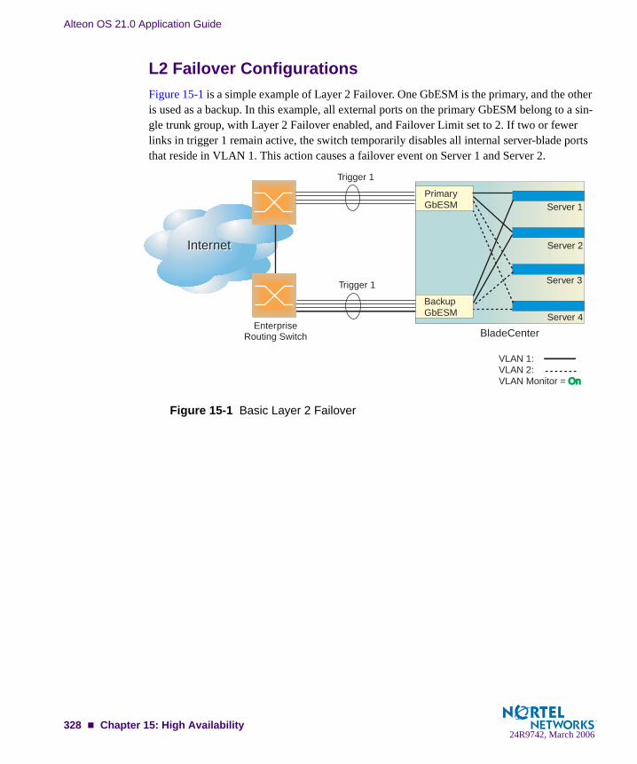
Alteon OS 21.0 Application Guide
L2 Failover ConfigurationsFigure 15-1 is a simple example of Layer 2 Failover. One GbESM is the primary, and the other is used as a backup. In this example, all external ports on the primary GbESM belong to a sin-gle trunk group, with Layer 2 Failover enabled, and Failover Limit set to 2. If two or fewer links in trigger 1 remain active, the switch temporarily disables all internal server-blade ports that reside in VLAN 1. This action causes a failover event on Server 1 and Server 2.
Figure 15-1 Basic Layer 2 Failover
InternetInternet
EnterpriseRouting Switch
PrimaryGbESM
Backup GbESM
Trigger 1
BladeCenter
Server 1
Server 3
Server 2
Server 4
Trigger 1
VLAN 1:VLAN 2:VLAN Monitor = OnOn
328 Chapter 15: High Availability24R9742, March 2006
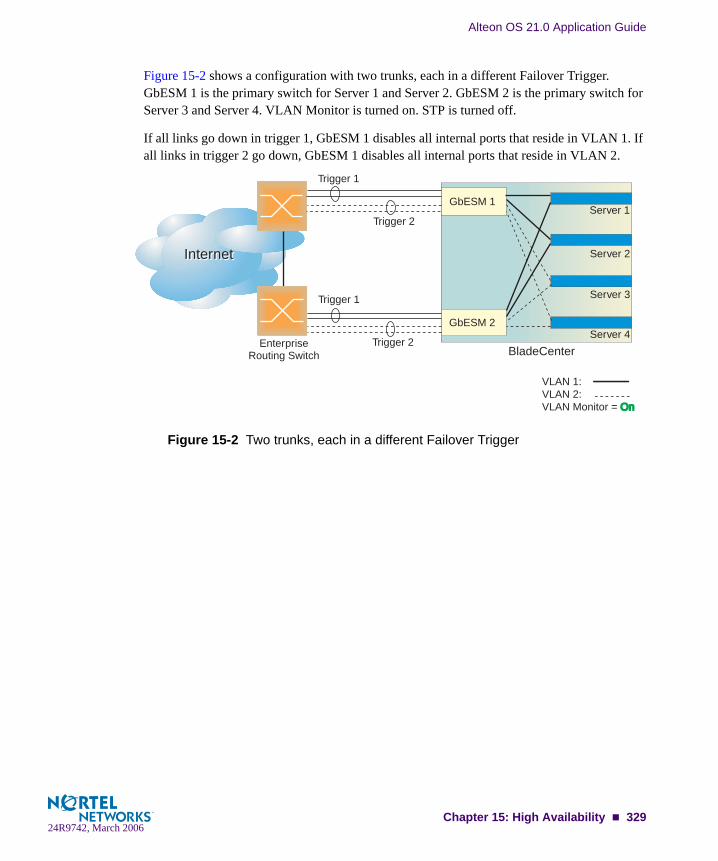
Alteon OS 21.0 Application Guide
Figure 15-2 shows a configuration with two trunks, each in a different Failover Trigger. GbESM 1 is the primary switch for Server 1 and Server 2. GbESM 2 is the primary switch for Server 3 and Server 4. VLAN Monitor is turned on. STP is turned off.
If all links go down in trigger 1, GbESM 1 disables all internal ports that reside in VLAN 1. If all links in trigger 2 go down, GbESM 1 disables all internal ports that reside in VLAN 2.
Figure 15-2 Two trunks, each in a different Failover Trigger
InternetInternet
EnterpriseRouting Switch
GbESM 1
GbESM 2
Trigger 2
Trigger 1
Trigger 1
Trigger 2BladeCenter
VLAN 1:VLAN 2:VLAN Monitor = OnOn
Server 1
Server 3
Server 2
Server 4
Chapter 15: High Availability 32924R9742, March 2006
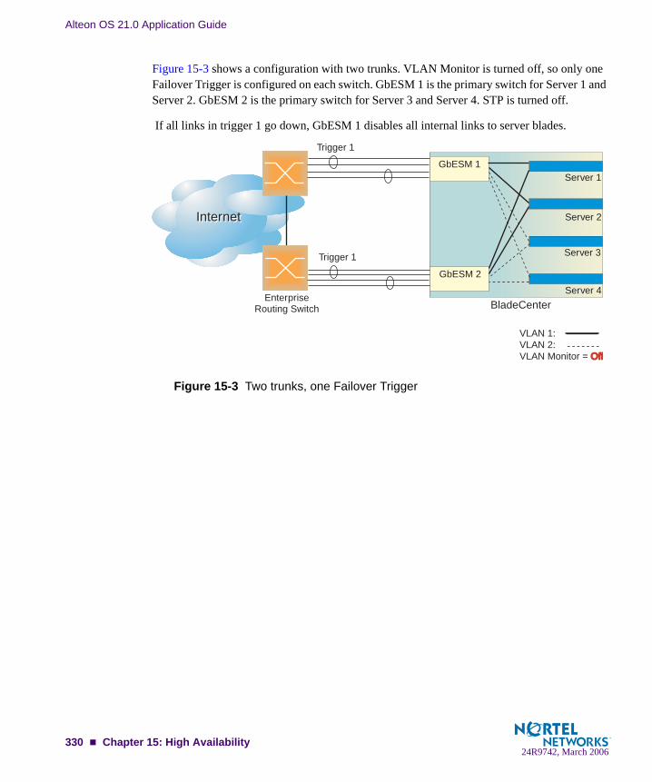
Alteon OS 21.0 Application Guide
Figure 15-3 shows a configuration with two trunks. VLAN Monitor is turned off, so only one Failover Trigger is configured on each switch. GbESM 1 is the primary switch for Server 1 and Server 2. GbESM 2 is the primary switch for Server 3 and Server 4. STP is turned off.
If all links in trigger 1 go down, GbESM 1 disables all internal links to server blades.
Figure 15-3 Two trunks, one Failover Trigger
InternetInternet
EnterpriseRouting Switch
GbESM 1
GbESM 2
Trigger 1
Trigger 1
BladeCenter
Server 1
VLAN 1:VLAN 2: VLAN Monitor = OffOff
Server 3
Server 2
Server 4
330 Chapter 15: High Availability24R9742, March 2006

Alteon OS 21.0 Application Guide
Configuring Trunk FailoverThe following procedure pertains to example 1, as shown in Figure 15-1.
1. Configure Network Adapter Teaming on the servers.
2. Define a trunk group on the GbESM.
3. Configure Failover parameters.
4. Apply and verify the configuration.
5. Save your new configuration changes.
>> # /cfg/l2/trunk 1 (Select trunk group 1)>> Trunk group 1# add EXT1 (Add port EXT1 to trunk group 1)>> Trunk group 1# add EXT2 (Add port EXT2 to trunk group 1)>> Trunk group 1# add EXT3 (Add port EXT3 to trunk group 1)>> Trunk group 1# add EXT4 (Add port EXT4 to trunk group 1)>> Trunk group 1# ena (Enable trunk group 1)
>> # /cfg/failovr/on (Turn Failover on)>> Failover# trigger 1 (Select trigger group 1)>> Trigger 1# ena (Enable trigger group 1)>> Trigger 1# limit 2 (Set Failover limit to 2 links)>> Trigger 1# amon (Select Auto Monitor menu)>> Auto Monitor# addtrnk 1 (Add trunk group 1)
>> Auto Monitor# apply (Make your changes active)>> Auto Monitor# cur (View current trunking configuration)
>> Auto Monitor# save (Save for restore after reboot)
Chapter 15: High Availability 33124R9742, March 2006

Alteon OS 21.0 Application Guide
VRRP OverviewIn a high-availability network topology, no device can create a single point-of-failure for the network or force a single point-of-failure to any other part of the network. This means that your network will remain in service despite the failure of any single device. To achieve this usually requires redundancy for all vital network components.
VRRP enables redundant router configurations within a LAN, providing alternate router paths for a host to eliminate single points-of-failure within a network. Each participating VRRP-capable routing device is configured with the same virtual router IP address and ID number. One of the virtual routers is elected as the master, based on a number of priority criteria, and assumes control of the shared virtual router IP address. If the master fails, one of the backup virtual routers will take control of the virtual router IP address and actively process traffic addressed to it.
VRRP ComponentsEach physical router running VRRP is known as a VRRP router.
Virtual RouterTwo or more VRRP routers can be configured to form a virtual router (RFC 2338). Each VRRP router may participate in one or more virtual routers. Each virtual router consists of a user-configured virtual router identifier (VRID) and an IP address.
Virtual Router MAC AddressThe VRID is used to build the virtual router MAC Address. The five highest-order octets of the virtual router MAC Address are the standard MAC prefix (00-00-5E-00-01) defined in RFC 2338. The VRID is used to form the lowest-order octet.
Owners and RentersOnly one of the VRRP routers in a virtual router may be configured as the IP address owner. This router has the virtual router’s IP address as its real interface address. This router responds to packets addressed to the virtual router’s IP address for ICMP pings, TCP connections, and so on.
There is no requirement for any VRRP router to be the IP address owner. Most VRRP installa-tions choose not to implement an IP address owner. For the purposes of this chapter, VRRP routers that are not the IP address owner are called renters.
332 Chapter 15: High Availability24R9742, March 2006

Alteon OS 21.0 Application Guide
Master and Backup Virtual RouterWithin each virtual router, one VRRP router is selected to be the virtual router master. See “Selecting the Master VRRP Router” on page 335 for an explanation of the selection process.
NOTE – If the IP address owner is available, it will always become the virtual router master.
The virtual router master forwards packets sent to the virtual router. It also responds to Address Resolution Protocol (ARP) requests sent to the virtual router's IP address. Finally, the virtual router master sends out periodic advertisements to let other VRRP routers know it is alive and its priority.
Within a virtual router, the VRRP routers not selected to be the master are known as virtual router backups. Should the virtual router master fail, one of the virtual router backups becomes the master and assumes its responsibilities.
Virtual Interface RouterAt Layer 3, a Virtual Interface Router (VIR) allows two VRRP routers to share an IP interface across the routers. VIRs provide a single Destination IP (DIP) for upstream routers to reach various destination networks, and provide a virtual default Gateway.
NOTE – Every VIR must be assigned to an IP interface, and every IP interface must be assigned to a VLAN. If no port in a VLAN has link up, the IP interface of that VLAN is down, and if the IP interface of a VIR is down, that VIR goes into INIT state.
Virtual Server RouterAlteon OS supports virtual server routers, which extend the benefits of VRRP to virtual server IP addresses that are used to perform SLB.
Virtual server routers operate for virtual server IP addresses in much the same manner as Vir-tual Interface Routers operate for IP interfaces. A master is negotiated via a bidding process, during which information about each VRRP router's priority is exchanged. Only the master can process packets that are destined for the virtual server IP address and respond to ARP requests.
One difference between virtual server routers and virtual interface routers is that a virtual server router cannot be an IP address owner. All virtual server routers are renters.
All virtual routers, whether virtual server routers or virtual interface routers, operate indepen-dently of one another; that is, their priority assignments, advertisements, and master negotia-tions are separate. For example, when you configure a VRRP router's priority in a virtual server router, you are not affecting that VRRP router's priority in any virtual interface router or
Chapter 15: High Availability 33324R9742, March 2006

Alteon OS 21.0 Application Guide
any other virtual server router of which it is a part. However, because of the requirement that MAC addresses be unique on a LAN, VRIDs must be unique among all virtual routers, whether virtual interface routers or virtual server routers.
The GbE Switch Modules in Figure 15-4 have been configured as VRRP routers. Together, they form a virtual router.
Figure 15-4 A VRRP Router
GbE Switch Module 1 in Figure 15-4 has a higher priority and, therefore, becomes the virtual router master. GbE Switch Module 2 is a virtual router backup.
The virtual server router has been assigned a VRID = 1. Therefore, both of the VRRP routers have a MAC address = 00-00-5E-00-01-01.
InternetInternet
EnterpriseRouting Switch
VIP = 205.178.13.226VRID = 1Router #2 = Backup StandbyVR IP address = 205.178.13.226MAC address = 00.00.5E.00.01.01Priority = 100IP interface = 205.178.13.225
VIP = 205.178.13.226VRID = 1Router #2 = Master ActiveVR IP address = 205.178.13.226MAC address = 00.00.5E.00.01.01Priority = 101IP interface = 205.178.13.224
GbESM 1
GbESM 2
Servers
334 Chapter 15: High Availability24R9742, March 2006
Alteon OS 21.0 Application Guide
VRRP OperationOnly the virtual router master responds to ARP requests. Therefore, the upstream routers only forward packets destined to the Virtual IP (VIP) to the Virtual Server Router master. The mas-ter also responds to ICMP ping requests. The backup does not forward any traffic on behalf of the virtual server router nor does it respond to ARP requests.
If the master is not available, the backup becomes the master and takes over responsibility for packet forwarding and responding to ARP requests.
Selecting the Master VRRP RouterEach VRRP router is configured with a priority between 1–254. A bidding process determines which VRRP router is or becomes the master—the VRRP router with the highest priority.
The master periodically sends advertisements to an IP multicast address. As long as the back-ups receive these advertisements, they remain in the backup state. If a backup does not receive an advertisement for three advertisement intervals, it initiates a bidding process to determine which VRRP router has the highest priority and takes over as master.
If, at any time, a backup determines that it has higher priority than the current master does, it can preempt the master and become the master itself, unless configured not to do so. In pre-emption, the backup assumes the role of master and begins to send its own advertisements. The current master sees that the backup has higher priority and will stop functioning as the master.
A backup router can stop receiving advertisements for one of two reasons—the master can be down, or all communications links between the master and the backup can be down. If the master has failed, it is clearly desirable for the backup (or one of the backups, if there is more than one) to become the master.
NOTE – If the master is healthy but communication between the master and the backup has failed, there will then be two masters within the virtual router. To prevent this from happening, configure redundant links to be used between the switches that form a virtual router.
Chapter 15: High Availability 33524R9742, March 2006
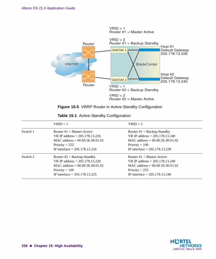
Alteon OS 21.0 Application Guide
Figure 15-5 VRRP Router in Active-Standby Configuration
Table 15-1 Active-Standby Configuration
VRID = 1 VRID = 2
Switch 1 Router #1 = Master-ActiveVR IP address = 205.178.13.226MAC address = 00.00.5E.00.01.01Priority = 255IP interface = 205.178.13.226
Router #1 = Backup-StandbyVR IP address = 205.178.13.240MAC address = 00.00.5E.00.01.02Priority = 100IP interface = 205.178.13.239
Switch 2 Router #2 = Backup-StandbyVR IP address = 205.178.13.226MAC address = 00.00.5E.00.01.01Priority = 100IP interface = 205.178.13.225
Router #1 = Master-ActiveVR IP address = 205.178.13.240MAC address = 00.00.5E.00.01.02Priority = 255IP interface = 205.178.13.240
InternetInternet BladeCenterBladeCenter
GbESM 1
GbESM 2
336 Chapter 15: High Availability24R9742, March 2006

Alteon OS 21.0 Application Guide
Failover MethodsWith service availability becoming a major concern on the Internet, service providers are increasingly deploying Internet traffic control devices, such as application switches, in redun-dant configurations. Traditionally, these configurations have been hot-standby configurations, where one switch is active and the other is in a standby mode. A non-VRRP hot-standby con-figuration is shown in the figure below:
Figure 15-6 A Non-VRRP, Hot-standby Configuration
While hot-standby configurations increase site availability by removing single points-of-fail-ure, service providers increasingly view them as an inefficient use of network resources because one functional application switch sits by idly until a failure calls it into action. Service providers now demand that vendors' equipment support redundant configurations where all devices can process traffic when they are healthy, increasing site throughput and decreasing user response times when no device has failed.
Alteon OS high availability configurations are based on VRRP. The Alteon OS implementa-tion of VRRP includes proprietary extensions to accommodate Layer 4 though Layer 7 appli-cation switching features.
The Alteon OS implementation of VRRP supports three modes of high availability:
Active-Standby—based on standard VRRP, as defined in RFC 2338Active-Active—based on proprietary Alteon OS extensions to VRRPHot-Standby—supports Server Load Balancing when you have configured Network Adapter Teaming on your server blades
Primary SwitchIP: 200.200.200.100
Secondary SwitchIP: 200.200.200.101
InternetServers
Chapter 15: High Availability 33724R9742, March 2006
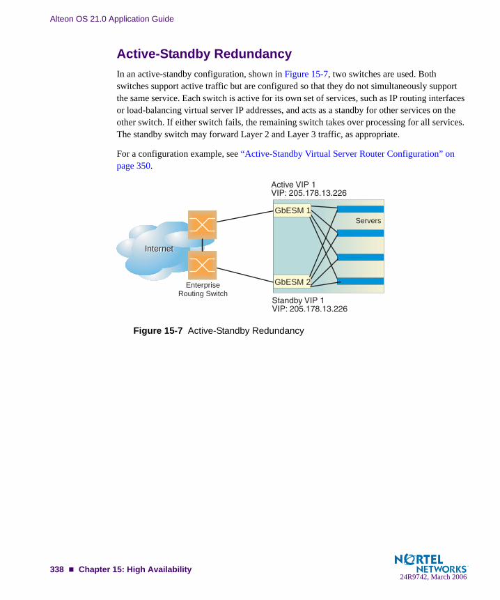
Alteon OS 21.0 Application Guide
Active-Standby RedundancyIn an active-standby configuration, shown in Figure 15-7, two switches are used. Both switches support active traffic but are configured so that they do not simultaneously support the same service. Each switch is active for its own set of services, such as IP routing interfaces or load-balancing virtual server IP addresses, and acts as a standby for other services on the other switch. If either switch fails, the remaining switch takes over processing for all services. The standby switch may forward Layer 2 and Layer 3 traffic, as appropriate.
For a configuration example, see “Active-Standby Virtual Server Router Configuration” on page 350.
Figure 15-7 Active-Standby Redundancy
InternetInternet
EnterpriseRouting Switch
GbESM 1
GbESM 2
Servers
338 Chapter 15: High Availability24R9742, March 2006

Alteon OS 21.0 Application Guide
Active-Active RedundancyIn an active-active configuration, two switches provide redundancy for each other, with both active at the same time on different VIPs.
Alteon OS has extended VRRP to include virtual servers, allowing full active/active redun-dancy between its Layer 4 switches. In an active-active configuration, shown in Figure 15-8, both switches can actively process traffic for given IP routing interfaces or load-balancing vir-tual servers (VIPs).
Figure 15-8 Active-Active Redundancy
In the example above, one switch is the master for VIP 1, but is the standby for VIP 2. The other switch is the master for VIP 2, but is the standby for VIP 1. Therefore, both switches are actively processing traffic simultaneously.
For configuration examples, see “Active-Active VIR and VSR Overview” on page 352 and “Active-Active Server Load Balancing Configuration” on page 353.
InternetInternet
EnterpriseRouting Switch
GbESM 1
GbESM 2
Servers
Chapter 15: High Availability 33924R9742, March 2006

Alteon OS 21.0 Application Guide
Hot-Standby RedundancyIn a VRRP-based hot-standby configuration, a Spanning Tree Group (STG) is not needed to eliminate bridge loops. Disabling Spanning Tree speeds up failover when a switch fails. The standby switch blocks all ports configured as standby ports, whereas the master switch enables these same ports. Consequently, on a given switch, all virtual routers are either master or standby; they cannot change state individually.
To provide as much flexibility as possible, hot-standby is now based on VRRP. In a hot-standby configuration, two or more switches provide redundancy for each other. One switch is elected master and actively processes Layer 4 traffic. The other switches (the standbys) assume the master role should the master fail.
There are three components to the VRRP-based, hot-standby model:
the virtual router group (this page)additional Layer 4 port states (page 268)configuration synchronization options (page 269)
The hot-standby model is shown in Figure 15-9.
Figure 15-9 Hot-Standby Redundancy
Virtual Router GroupThe virtual router group ties all virtual routers on the switch together as a single entity. By def-inition, hot-standby requires that all virtual routers failover as a group, and not individually. As members of a group, all virtual routers on the switch (and therefore the switch itself), are in either a master or standby state.
The virtual router group cannot be used for active-active configurations or any other configura-tion that require shared interfaces.
EnterpriseRouting Switch
Active
Standby
InterswitchLink
NIC 1 IP = 10.10.10.1NIC 2 IP = 10.10.10.1
NIC 1 IP = 10.10.10.2NIC 2 IP = 10.10.10.2
GbESM 1
GbESM 2
340 Chapter 15: High Availability24R9742, March 2006

Alteon OS 21.0 Application Guide
A VRRP group has the following characteristics:
When enabled, all virtual routers behave as one entity, and all group settings override any individual virtual router settings.
All individual virtual routers, once the VRRP group is enabled, assume the group’s track-ing and priority.
When one member of a VRRP group fails, the priority of the group decreases, and the state of the entire switch changes from Master to Standby.
If a switch is in the standby state, Layer 4 processing is still enabled. If a virtual server is not a virtual router, the standby switch can still process traffic addressed to that virtual server IP address. Filtering is also still functional. Only traffic addressed to virtual server routers is not processed.
Each VRRP advertisement can include up to 128 addresses. All virtual routers are advertised within the same packet, conserving processing and buffering resources.
Hot-Standby and Interswitch Port StatesThe second part of the solution involves introducing two additional Layer 4 port states, hot-standby and interswitch:
Links that attach to the standby switch must be configured as hot-standby using /cfg/slb/port x/hotstan.Links that are used by VRRP to deliver updates are configured as intersw, or inter-switch links (not to be confused with Cisco’s ISL). The command to configure one or more ports as interswitch links is /cfg/slb/port <port number>/intersw.
The hot-standby switch listens to the master’s VRRP updates. After an interval period has expired without receiving a update, the standby switch takes over. Enabling hot-standby on a switch port allows the hot-standby algorithm to control the forwarding state of the port. If a switch is master, the forwarding states of the hot-standby ports are enabled. If a switch is standby, the hot-standby ports are disabled from forwarding or receiving traffic.
NOTE – The VRRP hot-standby approach does not support single-link failover. If one hot-standby port loses link, the entire switch must become master to eliminate loss of connectivity.
The forwarding states of non-hot-standby ports are not controlled via the hot-standby algo-rithm, allowing the additional ports on the switches to provide added port density. The client ports on both switches should be able to process or forward traffic to the master switch.
Chapter 15: High Availability 34124R9742, March 2006

Alteon OS 21.0 Application Guide
The inter-switch port state is only a place holder. Its presence forces the user to configure a inter-switch link when hot-standby is globally enabled and prohibits the inter-switch link from also being a hot-standby link for VRRP advertisements. These advertisements must be able to reach the standby switch.
NOTE – Nortel Networks recommends that you use a dedicated interswitch link. However, you can use the interswitch link to connect to an upstream switch, and process traffic. Because the ports in the interswitch link are not directly connected, traffic congestion could slow communi-cation of VRRP status between the switches.
Synchronizing ConfigurationsThe final piece in configuring a high-availability solution includes the addition of synchroniza-tion options to simplify the manual configuration. Configuration options have been added to refine what is synchronized, to whom, and to disable synchronizing certain configurations. These options include proxy IP addresses, Layer 4 port configuration, filter configuration, real servers, and virtual router priorities.
Also, a peer menu (cfg/slb/sync/peer) has been added to allow the user to configure the IP addresses of the switches that should be synchronized. This provides added synchroni-zation validation but does not require the users to enter the IP address of the redundant switch for each synchronization.
For more information on synchronizing configurations between two switches, see “Synchro-nizing Switch Configurations” on page 346.
For a configuration example, see “Hot-Standby Configuration” on page 361.
342 Chapter 15: High Availability24R9742, March 2006
Alteon OS 21.0 Application Guide
Alteon OS extensions to VRRPThis section describes the following VRRP enhancements that are implemented in Alteon OS:
Virtual Server Routers
Tracking VRRP Router Priority
Virtual Server RoutersAlteon OS supports virtual server routers, which extend the benefits of VRRP to virtual server IP addresses that are used to perform SLB.
Virtual server routers operate for virtual server IP addresses in much the same manner as Vir-tual Interface Routers operate for IP interfaces. A master is negotiated via a bidding process, during which information about each VRRP router's priority is exchanged. Only the master can process packets that are destined for the virtual server IP address and respond to ARP requests.
One difference between virtual server routers and virtual interface routers is that a virtual server router cannot be an IP address owner. All virtual server routers are renters.
All virtual routers, whether virtual server routers or virtual interface routers, operate indepen-dently of one another; that is, their priority assignments, advertisements, and master negotia-tions are separate. For example, when you configure a VRRP router's priority in a virtual server router, you are not affecting that VRRP router's priority in any virtual interface router or any other virtual server router of which it is a part. However, because of the requirement that MAC addresses be unique on a LAN, VRIDs must be unique among all virtual routers, whether virtual interface routers or virtual server routers.
Tracking VRRP Router PriorityAlteon OS supports a tracking function that dynamically modifies the priority of a VRRP router, based on its current state. The objective of tracking is to have, whenever possible, the master bidding processes for various virtual routers in a LAN converge on the same switch. Tracking ensures that the selected switch is the one that offers optimal network performance. For tracking to have any effect on virtual router operation, preemption must be enabled.
NOTE – Tracking only affects active-standby configurations. It does not have any effect on active-active configurations.
Chapter 15: High Availability 34324R9742, March 2006

Alteon OS 21.0 Application Guide
Alteon OS can track the attributes listed in Table 15-2:
Table 15-2 VRRP Tracking Parameters
Parameter Description
Number of virtual routers in master mode on the switch/cfg/l3/vrrp/track/vr
Useful for ensuring that traffic for any particular client/server pair is handled by the same switch, increasing rout-ing and load-balancing efficiency. This parameter influ-ences the VRRP router's priority in both virtual interface routers and virtual server routers.
Number of IP interfaces on the switch that are active (“up”)/cfg/l3/vrrp/track/ifs
Helps elect the virtual routers with the most available routes as the master. (An IP interface is considered active when there is at least one active port on the same VLAN.) This parameter influences the VRRP router's priority in both virtual interface routers and virtual server routers.
Number of active ports on the same VLAN/cfg/l3/vrrp/track/ports
Helps elect the virtual routers with the most available ports as the master. This parameter influences the VRRP router's priority in both virtual interface routers and virtual server routers.Note: In a Hot-Standby configuration, only external ports are tracked.
Number of physical switch ports that have active Layer 4 processing on the switch/cfg/l3/vrrp/track/l4pts
Helps elect the main Layer 4 switch as the master. This parameter influences the VRRP router's prior-ity in both virtual interface routers and virtual server routers. Note: In a Hot-Standby configuration, only external ports are tracked.
Number of healthy real servers behind the virtual server IP address that is the same as the IP address of the virtual server router on the switch/cfg/l3/vrrp/track/reals
Helps elect the switch with the largest server pool as the master, increasing Layer 4 efficiency. This parameter influences the VRRP router's priority in virtual server routers only.
344 Chapter 15: High Availability24R9742, March 2006

Alteon OS 21.0 Application Guide
Each tracked parameter has a user-configurable weight associated with it. As the count associ-ated with each tracked item increases (or decreases), so does the VRRP router's priority, sub-ject to the weighting associated with each tracked item. If the priority level of a standby is greater than that of the current master, then the standby can assume the role of the master.
See “Configuring the Switch for Tracking” on page 348 for an example on how to configure the switch for tracking VRRP priority.
In networks where the Hot-standby Router Protocol (HSRP) is used for establishing router failover, the num-ber of Layer 4 client-only ports that receive HSRP advertisements/cfg/l3/vrrp/track/hsrp
Helps elect the switch closest to the master HSRP router as the master, optimizing routing efficiency. This parameter influences the VRRP router's prior-ity in both virtual interface routers and virtual server routers.Note: In a Hot-Standby configuration, HSRP is not tracked.
Tracking HSRV on VLAN/cfg/l3/vrrp/track/hsrv
Hot-Standby router on VLAN (HSRV) is used in VLAN-tagged environments. Enable this option to increment only that VRRP instance that is on the same VLAN as the tagged HSRP master-flagged packet. The default value for this command is dis-abled. Note: In a Hot-Standby configuration, HSRV is not tracked.
Table 15-2 VRRP Tracking Parameters
Parameter Description
Chapter 15: High Availability 34524R9742, March 2006

Alteon OS 21.0 Application Guide
Virtual Router Deployment ConsiderationsReview the following issues described in this section to prevent network problems when deploying virtual routers:
Synchronizing Active/Active Failover Assigning VRRP Virtual Router ID Configuring the Switch for Tracking Synchronizing Switch Configurations
Synchronizing Switch ConfigurationsAs noted above, each VRRP-capable switch is autonomous. Switches in a virtual router need not be identically configured. As a result, configurations cannot be synchronized automatically.
For user convenience, it is possible to synchronize a configuration from one VRRP-capable switch to another using the /oper/slb/sync command. However, care must be taken when using this command to avoid unexpected results. All server load balancing, port configu-rations, filter configurations, and VRRP parameters can be synchronized using the /oper/slb/synch command.
NOTE – Before you synchronize the configuration between two switches, a peer must be con-figured on each switch. Switches being synchronized must use the same administrator pass-word.
Configure the two switches as peers to each other. From Switch 1, configure Switch 2 as a peer and specify its IP address as follows:
>> Main # /cfg/slb/sync (Select the synchronization menu)>> Config Synchronization # peer 1 (Select a peer)>> Peer Switch 1 # addr <IP address> (Assign switch 2 IP address)>> Peer Switch 1 # enable (Enable peer switch)>> Peer Switch 1 # apply (Make your changes active)>> Peer Switch 1 # save (Save for restore after reboot)
346 Chapter 15: High Availability24R9742, March 2006

Alteon OS 21.0 Application Guide
Similarly, from Switch 2, configure Switch 1 as a peer and specify its IP address as follows:
Port specific parameters, such as what filters are applied and enabled on what ports, are part of what is pushed by the /oper/slb/synch command. Thus, if the /oper/slb/synch command is used, it is highly recommended that the hardware configurations and network con-nections of all switches in the virtual router be identical; that is, each switch should be the same model, have the same line cards in the same slots (if modular) and have the same ports connected to the same external network devices. Otherwise, unexpected results may occur when the /oper/slb/synch command attempts to configure a non-existent port or applies an inappropriate configuration to a port.
Synchronizing Active/Active FailoverWith VRRP and active/active failover, the primary and secondary switches do not require iden-tical configurations and port topology. Each switch can be configured individually with differ-ent port topology, SLB, and filters. If you would rather force two active/active switches to use identical settings, you can synchronize their configuration using the following command:.
The sync command copies the following settings to the switch at the specified IP interface address:
VRRP settingsSLB settings (including port settings)Filter settings (including filter port settings)Proxy IP settings
If you perform the sync command, you should check the configuration on the target switch to ensure that the settings are correct.
For more information on synchronizing configurations between two switches, see “Synchro-nizing Switch Configurations” on page 346.
>> Main # /cfg/slb/sync (Select the synchronization menu)>> Config Synchronization # peer 1 (Select a peer)>> Peer Switch 1 # addr <IP address> (Assign switch 1 IP address)>> Peer Switch 1 # enable (Enable peer switch)>> Peer Switch 1 # apply (Make your changes active)>> Peer Switch 1 # save (Save for restore after reboot)
>> Main# /oper/slb/sync
Chapter 15: High Availability 34724R9742, March 2006

Alteon OS 21.0 Application Guide
Assigning VRRP Virtual Router IDDuring the software upgrade process, VRRP virtual router IDs will be automatically assigned if failover is enabled on the switch. When configuring virtual routers at any point after upgrade, virtual router ID numbers (/cfg/l3/vrrp/vr #/vrid) must be assigned. The virtual router ID may be configured as any number between 1 and 255.
Configuring the Switch for TrackingTracking configuration largely depends on user preferences and network environment. Con-sider the configuration shown in Figure 15-10 on page 350. Assume the following behavior on the network:
Switch 1 is the master router upon initialization.
If switch 1 is the master and it has one fewer active servers than switch 2, then switch 1 remains the master.
This behavior is preferred because running one server down is less disruptive than bring-ing a new master online and severing all active connections in the process.
If switch 1 is the master and it has two or more active servers fewer than switch 2, then switch 2 becomes the master.
If switch 2 is the master, it remains the master even if servers are restored on switch 1 such that it has one fewer or an equal number of servers.
If switch 2 is the master and it has one active server fewer than switch 1, then switch 1 becomes the master.
The user can implement this behavior by configuring the switch for tracking as follows:
1. Set the priority for switch 1 to the default value of 100.
2. Set the priority for switch 2 to 96.
3. On both switches, enable tracking based on the number of virtual routers in master mode on the switch and set the value = 5.
4. On both switches, enable tracking based on the number of healthy real servers behind the VIP address. The VIP address is the same as the IP address of the virtual server router on the switch. Set the value = 6.
Initially, switch 1 (Figure 15-10 on page 350) will have a priority of 100 (base value) + 5 (ini-tially it is the master) + 24 (4 active real servers * 6 per real server) = 129.
Switch 2 will have a priority of 96 (base value) + 24 (4 active real servers * 6 per real server) = 120.
348 Chapter 15: High Availability24R9742, March 2006

Alteon OS 21.0 Application Guide
If a server attached to switch 1 fails, then switch 1’s priority will be reduced by 6 to 123. Since 123 is greater than 120 (switch 2's priority), switch 1 will remain the master.
If a second server attached to switch 1 fails, then switch 1’s priority will be reduced by 6 more to 117. Since 117 is less than 120 (switch 2’s priority), then switch 2 will become the Master. At this point, switch 1’s priority will fall by 5 more and switch 2’s will rise by 5 because the switches are tracking how many masters they are running. So, switch 1’s priority will settle out at 112 and switch 2’s priority at 125.
When both servers are restored to switch 1, that switch’s priority will rise by 12 (2 healthy real servers * 6 per healthy server) to 124. Since 124 is less than 125, switch 2 will remain the mas-ter.
If, at this point, a server fails on switch 2, its priority will fall by 6 to 119. Since 119 is less than 124, switch 1 will become the Master. Its priority will settle out at 129 (since it’s now the mas-ter) while switch 2’s priority will drop by 5 more to 114.
You can see from this example that the user’s goals were met by the configured tracking parameters.
NOTE – There is no shortcut to setting tracking parameters. The goals must first be set and the outcomes of various configurations and scenarios analyzed to find settings that meet the goals.
Chapter 15: High Availability 34924R9742, March 2006

Alteon OS 21.0 Application Guide
High Availability ConfigurationsGbE Switch Modules offer flexibility in implementing redundant configurations. This section discusses a few of the more useful and easily deployed configurations:
“Active-Standby Virtual Server Router Configuration” on page 350“Active-Active VIR and VSR Overview” on page 352“Active-Active Server Load Balancing Configuration” on page 353“Hot-Standby Configuration” on page 361“Four-switch configuration” on page 368“Inter-Chassis Redundancy Link” on page 372“Layer 2 Trunk Failover with VRRP” on page 376
Active-Standby Virtual Server Router ConfigurationFigure 15-10 shows an example configuration where two GbE Switch Modules are used as VRRP routers in an active-standby configuration, implementing a virtual server router. In this configuration, when both switches are healthy, only the master responds to packets sent to the virtual server IP address.
Figure 15-10 Active-Standby High-Availability Configuration
Although this example shows only two switches, there is no limit on the number of switches used in a redundant configuration. It is possible to implement an active-standby configuration across all the VRRP-capable switches in a LAN.
InternetInternet
EnterpriseRouting Switch
NIC 1: 10.10.10.101/24 (RIP 1, GbESM 1)NIC 2: 10.10.11.101/24 (RIP 1, GbESM 2)
NIC 1: 10.10.10.102/24 (RIP 2, GbESM 1)NIC 2: 10.10.11.102/24 (RIP 2, GbESM 2)
NIC 1: 10.10.10.103/24 (RIP 3, GbESM 1)NIC 2: 10.10.11.103/24 (RIP 3, GbESM 2)
NIC 1: 10.10.10.104/24 (RIP 4, GbESM 1)NIC 2: 10.10.11.104/24 (RIP 4, GbESM 2)
Server 1
Server 2
Server 3
Server 4
GbESM 1
GbESM 2
350 Chapter 15: High Availability24R9742, March 2006

Alteon OS 21.0 Application Guide
Each VRRP-capable switch in an active-standby configuration is autonomous. Switches in a virtual router need not be identically configured.
To implement the active-standby example, perform the following switch configuration:
1. Configure the appropriate Layer 2 and Layer 3 parameters on both switches.
This includes any required VLANs, IP interfaces, default gateways, and so on. If IP interfaces are configured, none should use the virtual server IP address described in Step 4.
2. Define all filters required for your network configuration.
Filters may be configured on one switch and synchronized with settings on the other switch (see Step 5 below).
3. Configure all required SLB parameters on GbESM 1.
For the purposes of this example, assume that switch 1 in Figure 15-10 is configured in this step. Required Layer 4 parameters include a VIP = 205.178.13.226 and one real server group with four real servers, RIP1 = 10.10.10.101, RIP2 = 10.10.10.102, RIP3 = 10.10.10.103, and RIP4 = 10.10.10.104.
4. Configure the VRRP parameters on GbESM 1.
This configuration includes VRID = 2, VIP = 205.178.13.226 and the priority. Enable tracking and set the parameters appropriately (refer to “Configuring the Switch for Tracking” on page 348).
5. Synchronize the SLB and VRRP configurations by synchronizing the configuration from GbESM 1 to GbESM 2.
Use the /oper/slb/sync command (see “Synchronizing Switch Configurations” on page 346).
6. Change the real servers in the GbESM 2 configuration to RIP = 10.10.11.101, RIP = 10.10.11.102, RIP =10.10.11.103, and RIP = 10.10.11.104.
Adjust GbESM 2’s priority (see “Configuring the Switch for Tracking” on page 348).
In this example, with GbESM 1 as the master, if a link between GbESM 1 and a server fails, the server will fail health checks and be taken out of the load-balancing algorithm. If tracking is enabled and is configured to take into account the number of healthy real servers for the Virtual Router's VIP address, GbESM 1’s priority will be reduced. If it is reduced to a value lower than GbESM 2’s priority, then GbESM 2 will assume the role of master. In this case, all active con-nections serviced by GbESM 1’s virtual server IP address are severed.
If the link between GbESM 1 and its Internet router fails, the protocol used to distribute traffic between the routers, for example, Open Shortest Path First (OSPF), will reroute traffic to the other router. GbESM 2 (standby) will act as a Layer 2/3 switch and forward all traffic destined to the virtual server IP address to GbESM 1.
Chapter 15: High Availability 35124R9742, March 2006

Alteon OS 21.0 Application Guide
If the entire GbESM 1 (master) fails, the protocol used to distribute traffic between the routers, such as OSPF, will reroute traffic to GbESM 2. GbESM 2 (standby) detects that the master has failed because it will stop receiving advertisements. The standby then assumes the master's responsibility of responding to ARP requests and issuing advertisements.
Active-Active VIR and VSR OverviewThere is no limit on the number of switches used in a high availability configuration. It is pos-sible to implement an active-active configuration and perform load sharing between all of the VRRP-capable switches in a LAN.
In an Active-Active configuration, when both switches are healthy, the load balanced packets are sent to the virtual server IP address, resulting in higher capacity and performance than when the switches are used in an Active-Standby configuration.
The switch on which a frame enters the virtual server router is the one that processes that frame. The ingress switch is determined by external factors, such as routing and STG settings.
NOTE – Each VRRP-capable switch is autonomous. There is no requirement that the switches in a virtual router be identically configured. Different switch models with different numbers of ports and different enabled services may be used in a virtual router.
In this configuration, if a link between a switch and a server fails, the server will fail health checks and its backup (attached to the other switch) is brought online. If a link between a switch and its Internet router fails, the protocol used to distribute traffic between the routers (for example, OSPF) will reroute traffic to the other router. Since all traffic now enters the vir-tual server router on one switch, that switch processes all incoming connections.If an entire master switch fails, the standby switch detects this failure because it stops receiving advertisements. The standby assumes the master's responsibility of responding to ARP requests and issuing advertisements.Be cautious before setting the maximum connections (maxconn) metric in this configuration. The maxcon number is not shared between switches. Therefore, if a server is used for normal operation by one switch and is activated simultaneously as a backup by the other switch, the total number of possible connections to that server is the sum of the maximum connection limits defined for it on both switches.
352 Chapter 15: High Availability24R9742, March 2006

Alteon OS 21.0 Application Guide
Active-Active Server Load Balancing ConfigurationFigure 15-11 two GbE Switch Modules are used as VRRP routers in an active-active configu-ration implementing a virtual server router. As noted earlier, this is the preferred redundant configuration.
Figure 15-11 Active-Active High-Availability Configuration
In this example, you set up four virtual servers, each load balancing two servers, and providing one service (for example, HTTP) per virtual server.
You are load balancing HTTP and FTP. Each protocol is load balanced via a different virtual server. You could load balance all of these services on one VIP, but in this example, two dis-tinct virtual servers are used to illustrate the benefits of active/active failover. Set up one switch, dump out the configuration script (also called a text dump), edit it, and dump the edited configuration into the peer switch.
In this configuration, each GbE Switch Module has a common external subnet, that contains the VIPs and the default gateway.
Each GbESM has its unique internal subnet, connecting to one of the server NICs. Therefore, each server contains a NIC connected to each GbESM on its own unique subnet. In this case, NIC 1 contains an IP on 10.10.10.x subnet, with a default gateway of 10.10.10.1 (real server interface on GbESM 1). NIC 2 contains an IP on 10.10.11.x subnet with a default gateway of 10.10.11.2 (real server interface on GbESM 2).
InternetInternet
EnterpriseRouting Switch
NIC 1: 10.10.10.104/24 (RIP 4, GbESM 1)NIC 2: 10.10.11.104/24 (RIP 4, GbESM 2)
NIC 1: 10.10.10.101/24 (RIP 1, GbESM 1)NIC 2: 10.10.11.101/24 (RIP 1, GbESM 2)
NIC 1: 10.10.10.102/24 (RIP 2, GbESM 1)NIC 2: 10.10.11.102/24 (RIP 2, GbESM 2)
NIC 1: 10.10.10.103/24 (RIP 3, GbESM 1)NIC 2: 10.10.11.103/24 (RIP 3, GbESM 2)
VIP 1: 205.178.13.226VIP 2: 205.178.13.227VIP 1: 205.178.13.226VIP 2: 205.178.13.227
(Master)(Backup)
VIP 1: 205.178.13.226VIP 2: 205.178.13.227VIP 1: 205.178.13.226VIP 2: 205.178.13.227 (Master)
(Backup)
Server 1
Server 2
Server 3
Server 4
GbESM 1
GbESM 2
Chapter 15: High Availability 35324R9742, March 2006

Alteon OS 21.0 Application Guide
NOTE – Configuring the switch for active-active failover should take no longer than 15 min-utes to complete. You can use either the Alteon OS Browser-Based Interface (BBI) or the Command Line Interface (CLI) for configuration.
Task 1: Configure Layer 2 and Layer 3 Parameters on GbESM 1
1. Define the VLANs.
In this configuration, set up one additional VLAN, for communication with the outside world (the ports connected to the upstream switches, toward the routers).
2. Define the IP interfaces.
The switch needs an IP interface for each subnet to which it is connected, so it can communi-cate with devices attached to it. Each interface must be placed in the appropriate VLAN. In our example, Interface 1 is in VLAN 1, Interface 2 is in VLAN 2.
To configure the internal IP interface for this example, enter the following commands from the CLI:
Repeat the commands for the external interface listed below:
IF 2—205.178.13.1 (VLAN 2)
NOTE – On GbE Switch Modules, you are permitted to configure more than one subnet per VLAN.
/cfg/l2/vlan 2 (Select VLAN 2)>> vlan 2 # add EXT2 (Add a port to the VLAN membership)Port EXT2 is an UNTAGGED port and its current PVID is 1.Confirm changing PVID from 1 to 2 [y/n]: y>> vlan 2 # ena (Enable VLAN 2)
/cfg/l3/if 1 (Select IP interface 1)>> IP Interface 1 # mask 255.255.255.0 (Assign subnet mask for the interface)>> IP Interface 1 # addr 10.10.10.1 (Assign IP address for the interface)>> IP Interface 1 # vlan 1 (Assign VLAN for the interface)>> IP Interface 1 # ena (Enable IP interface 1)
354 Chapter 15: High Availability24R9742, March 2006
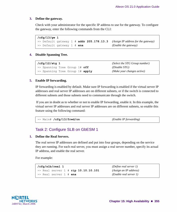
Alteon OS 21.0 Application Guide
3. Define the gateway.
Check with your administrator for the specific IP address to use for the gateway. To configure the gateway, enter the following commands from the CLI:
4. Disable Spanning Tree.
5. Enable IP forwarding.
IP forwarding is enabled by default. Make sure IP forwarding is enabled if the virtual server IP addresses and real server IP addresses are on different subnets, or if the switch is connected to different subnets and those subnets need to communicate through the switch.
If you are in doubt as to whether or not to enable IP forwarding, enable it. In this example, the virtual server IP addresses and real server IP addresses are on different subnets, so enable this feature using the following command:
Task 2: Configure SLB on GbESM 1
1. Define the Real Servers.
The real server IP addresses are defined and put into four groups, depending on the service they are running. For each real server, you must assign a real server number, specify its actual IP address, and enable the real server.
For example:
/cfg/l3/gw 1>> Default gateway 1 # addr 205.178.13.3 (Assign IP address for the gateway)>> Default gateway 1 # ena (Enable the gateway)
/cfg/l2/stg 1 (Select the STG Group number)>> Spanning Tree Group 1# off (Disable STG)>> Spanning Tree Group 1# apply (Make your changes active)
>> Main# /cfg/l3/frwd/on (Enable IP forwarding)
/cfg/slb/real 1 (Define real server 1)>> Real server 1 # rip 10.10.10.101 (Assign an IP address)>> Real server 1 # ena (Enable real server 1)
Chapter 15: High Availability 35524R9742, March 2006

Alteon OS 21.0 Application Guide
Repeat this sequence of commands for the following real servers:
RIP 2—10.10.10.102/24RIP 3—10.10.10.103/24RIP 4—10.10.10.104/24
2. Define the real server groups, adding the appropriate real servers.
This combines the three real servers into one service group:
Repeat this sequence of commands for the following real server group:
Group 2—Add RIP 1 through 4
3. Define the virtual servers.
After defining the virtual server IP addresses and associating them with a real server group number, you must tell the switch which IP ports/services/sockets you want to load balance on each VIP. You can specify the service by either the port number, service name, or socket num-ber.
Repeat this sequence of commands for the following virtual servers:
VIP 2—205.178.13.227 will load balance FTP ports 20 and 21 to Group 2
4. Define the client and server port states.
Defining a client port state tells that port to watch for any frames destined for the VIP and to load balance them if they are destined for a load-balanced service. Defining a server port state tells the port to the do the remapping (NAT) of the real server IP address back to the virtual server IP address. Note the following:
/cfg/slb/group 1 (Select real server group 1)>> Real server group 1# add 1 (Add real server 1 to group 1)>> Real server group 1# add 2 (Add real server 2 to group 1)>> Real server group 1# add 3 (Add real server 3 to group 1)>> Real server group 1# add 4 (Add real server 4 to group 1)
/cfg/slb/virt 1 (Select virtual server 1)>> Virtual server 1 # vip 205.178.13.226 (Assign a virtual server IP address)>> Virtual Server 1 # service 80 (Assign HTTP service port 80)>> Virtual server 1 http Service # group 1 (Associate virtual port to real group)>> Virtual server 1 http Service # ../ena (Enable the virtual server)
356 Chapter 15: High Availability24R9742, March 2006

Alteon OS 21.0 Application Guide
The ports connected to the upstream switches (the ones connected to the routers) will need to be in the client port state.
Configure the ports, using the following sequence of commands:
Task 3: Configure Virtual Router Redundancy on GbESM 1
1. Configure virtual routers 1 and 2.
These virtual routers will have the same IP addresses as the virtual server IP addresses. This is what tells the switch that these are virtual service routers (VSRs).
Configure a virtual router using the following sequence of commands:
Repeat this sequence of commands for the following virtual router 2:
VR 2 - VRID 2 - IF 2 (associate with IP interface #2)—Address 205.178.13.227
2. Set the renter priority for each virtual router.
Since you want GbESM 1 to be the master router, you need to bump the default virtual router priorities (which are 100 to 101 on virtual routers 1-2) to force GbESM 1 to be the master for virtual router 1.
Use the following sequence of commands:
/cfg/slb/port EXT2 (Select physical switch port EXT2)>> SLB port EXT2 # client ena (Enable client processing)>> SLB port EXT2 # ../port INT1 (Select physical switch port INT1)>> SLB port INT1 # server ena (Enable server processing)>> SLB port INT1 # ../port INT2 (Select physical switch port INT2)>> SLB port INT2 # server ena (Enable server processing)>> SLB port INT2 # ../port INT3 (Select physical switch port INT3)>> SLB port INT3 # server ena (Enable server processing)>> SLB port INT3 # ../port INT4 (Select physical switch port INT4)>> SLB port INT4 # server ena (Enable server processing)
/cfg/l3/vrrp/vr 1 (Select virtual router 1)>> Virtual router 1 vrid 1 (Set virtual router ID)>> Virtual router 1 addr 205.178.13.226 (Assign virtual router IP address)>> Virtual router 1 if 2 (Assign virtual router interface)>> Virtual router 1 ena (Enable virtual router 1)
/cfg/l3/vrrp/vr 1 (Select virtual router 1)>> Virtual router 1 prio 101 (Set virtual router priority)
Chapter 15: High Availability 35724R9742, March 2006

Alteon OS 21.0 Application Guide
NOTE – Since you want GbESM 1 to be the backup router for VIP 2, leave the priorities for virtual router 2 at the default of 100.
3. Configure priority tracking parameters for each virtual router.
For this example, the best parameter(s) on which to track is Layer 4 ports (l4pts).
Use the following commands:
This command sets the priority tracking parameter for virtual router 1, electing the virtual router with the most available ports as the master router. Repeat this command for virtual router 2:
VR 2 - Track l4pts
4. Apply and save your changes.
GbESM 1 configuration is complete.
Task 4: Configure Layer 2 and Layer 3 Parameters on GbESM 2
1. Define the VLANs.
In this configuration, set up one additional VLAN, for communication with the outside world (the ports connected to the upstream switches, toward the routers).
2. Define the IP interfaces.
The switch needs an IP interface for each subnet to which it is connected, so it can communi-cate with devices attached to it. Each interface must be placed in the appropriate VLAN. In our example, Interface 1 is in VLAN 1, Interface 2 is in VLAN 2.
/cfg/l3/vrrp/vr 1/track >> VRRP Virtual Router 1 Priority Tracking# l4pts ena
>> VRRP Virtual Router 1 Priority Tracking# apply(Make your changes active)>> VRRP Virtual Router 1 Priority Tracking# save(Save for restore after reboot)
/cfg/l2/vlan 2 (Select VLAN 2)>> vlan 2 # add EXT2 (Add a port to the VLAN membership)Port EXT2 is an UNTAGGED port and its current PVID is 1.Confirm changing PVID from 1 to 2 [y/n]: y>> vlan 2 # ena (Enable VLAN 2)
358 Chapter 15: High Availability24R9742, March 2006

Alteon OS 21.0 Application Guide
NOTE – On GbE Switch Modules, you may configure more than one subnet per VLAN.
To configure the IP interfaces for this example, enter the following commands from the CLI:
Repeat the commands for the interface listed below:
IF 2—205.178.13.2 (VLAN 2)
3. Define the gateway.
Check with your administrator for the specific IP address to use for the gateway. To configure the gateway, enter the following commands from the CLI:
4. Disable Spanning Tree.
5. Enable IP forwarding.
IP forwarding is enabled by default. Make sure IP forwarding is enabled if the virtual server IP addresses and real server IP addresses are on different subnets, or if the switch is connected to different subnets and those subnets need to communicate through the switch.
If you are in doubt as to whether or not to enable IP forwarding, enable it. In this example, the virtual server IP addresses and real server IP addresses are on different subnets, so enable this feature using the following command:
/cfg/l3/if 1 (Select IP interface 1)>> IP Interface 1 # mask 255.255.255.0 (Assign subnet mask for the interface)>> IP Interface 1 # addr 10.10.10.2 (Assign IP address for the interface)>> IP Interface 1 # vlan 1 (Assign VLAN for the interface)>> IP Interface 1 # ena (Enable IP interface 1)
/cfg/l3/gw 1>> Default gateway 1 # addr 205.178.13.3 (Assign IP address for the gateway)>> Default gateway 1 # ena (Enable the gateway)
/cfg/l2/stg 1 (Select the STG Group number)>> Spanning Tree Group 1# off (Disable STG)
/cfg/l3/frwd/on (Enable IP forwarding)>> IP Forwarding# apply (Make your changes active)>> IP Forwarding# save (Save for restore after reboot)
Chapter 15: High Availability 35924R9742, March 2006
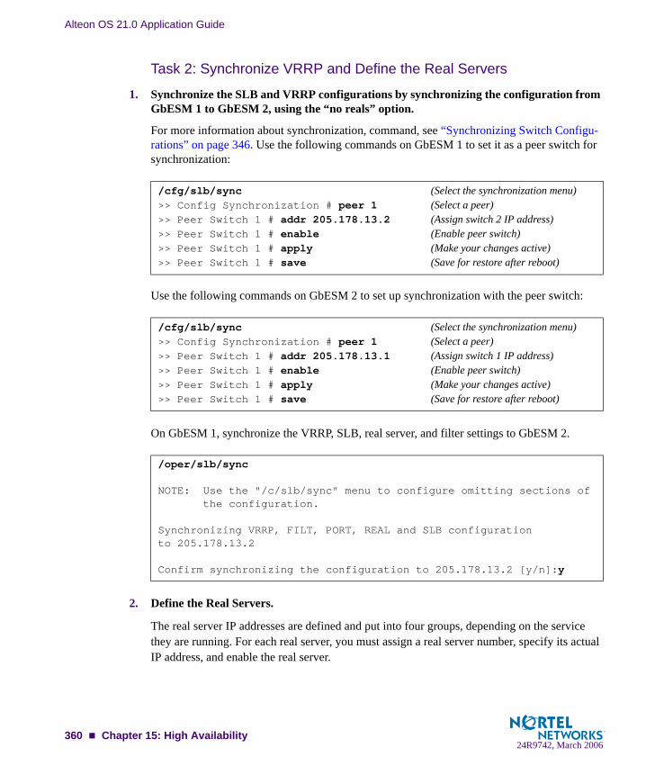
Alteon OS 21.0 Application Guide
Task 2: Synchronize VRRP and Define the Real Servers
1. Synchronize the SLB and VRRP configurations by synchronizing the configuration from GbESM 1 to GbESM 2, using the “no reals” option.
For more information about synchronization, command, see “Synchronizing Switch Configu-rations” on page 346. Use the following commands on GbESM 1 to set it as a peer switch for synchronization:
Use the following commands on GbESM 2 to set up synchronization with the peer switch:
On GbESM 1, synchronize the VRRP, SLB, real server, and filter settings to GbESM 2.
2. Define the Real Servers.
The real server IP addresses are defined and put into four groups, depending on the service they are running. For each real server, you must assign a real server number, specify its actual IP address, and enable the real server.
/cfg/slb/sync (Select the synchronization menu)>> Config Synchronization # peer 1 (Select a peer)>> Peer Switch 1 # addr 205.178.13.2 (Assign switch 2 IP address)>> Peer Switch 1 # enable (Enable peer switch)>> Peer Switch 1 # apply (Make your changes active)>> Peer Switch 1 # save (Save for restore after reboot)
/cfg/slb/sync (Select the synchronization menu)>> Config Synchronization # peer 1 (Select a peer)>> Peer Switch 1 # addr 205.178.13.1 (Assign switch 1 IP address)>> Peer Switch 1 # enable (Enable peer switch)>> Peer Switch 1 # apply (Make your changes active)>> Peer Switch 1 # save (Save for restore after reboot)
/oper/slb/sync
NOTE: Use the "/c/slb/sync" menu to configure omitting sections of the configuration.
Synchronizing VRRP, FILT, PORT, REAL and SLB configurationto 205.178.13.2
Confirm synchronizing the configuration to 205.178.13.2 [y/n]:y
360 Chapter 15: High Availability24R9742, March 2006

Alteon OS 21.0 Application Guide
For example:
Repeat this sequence of commands for the following real servers:
RIP 2—10.10.11.102/24RIP 3—10.10.11.103/24RIP 4—10.10.11.104/24
Task 3: Set Virtual Router Priorities
1. Set the renter priority for each virtual router.
Since you want GbESM 2 to be the master router for VIP 2, you need to bump the default vir-tual router priorities to force GbESM 2 to be the master for virtual router 2.
Use the following sequence of commands:
Set the priority of Virtual Router 1 to 100, so it becomes the backup for VIP 1:
GbESM 2 configuration is complete.
Hot-Standby ConfigurationThe primary application for VRRP-based Hot-Standby is to support Server Load Balancing when you have configured Network Adapter Teaming on your server blades. With Network Adapter Teaming, the NICs on each server share the same IP address, and are configured into a team. One NIC is the primary link, and the others are backup links. For more details, refer to “Configuring Teaming” in the Broadcom NetXtreme™ Gigabit Ethernet Adapter User Guide (http://www-306.ibm.com/pc/support/site.wss/MIGR-43152.html).
/cfg/slb/real 1 (Define real server 1)>> Real server 1 # rip 10.10.11.101 (Assign an IP address)>> Real server 1 # ena (Enable real server 1)
/cfg/l3/vrrp/vr 2 (Select virtual router 2)>> Virtual router 2# prio 101 (Set virtual router priority)
/cfg/l3/vrrp/vr 1 (Select virtual router 1)>> Virtual router 1# prio 100 (Set virtual router priority)>> Virtual router 1# apply (Make your changes active)>> Virtual router 1# save (Save for restore after reboot)
Chapter 15: High Availability 36124R9742, March 2006

Alteon OS 21.0 Application Guide
A hot-standby configuration allows all processes to failover to a standby switch if any type of failure should occur. All Virtual Interface Routers (VIRs) and all Virtual Service Routers (VSRs) are bundled into one Virtual Router group, and then they failover together. When there is a failure that causes the VRRP Master to failover to the Standby, then the original primary switch temporarily disables the internal server links, which, in turn, causes the NIC teams to failover as well.
NOTE – When using hot-standby redundancy, peer switches should have an equal number of connected ports.
The key to Hot-Standby is that the interswitch link (the link between switches) does not partic-ipate in Spanning Tree, so there are no loops in the topology (see Figure 15-12). Therefore, Spanning Tree is not required, and the switch will have failover times similar to standard VRRP. In complex networks, Spanning Tree convergence time can be much higher than 45-50 seconds.
If Hot-Standby is implemented in a looped environment, the hot-standby feature automatically disables the hot-standby ports on the VRRP Standby. If the Master switch should failover to the Standby switch, it would change the hot-standby ports from disabled to forwarding, with-out relying on Spanning Tree or manual intervention. Therefore, Spanning Tree must be dis-abled.
Figure 15-12 illustrates a common Hot-Standby implementation on a single blade server. Notice that the BladeCenter server NICs are configured into a team that shares the same IP address across both NICs. Because only one link can be active at a time, the hot-standby fea-ture controls the NIC failover by having the Standby switch disable its internal ports (holding down the server links).
Figure 15-12 Hot-Standby Configuration
InternetInternet
EnterpriseRouting Switch
Server 2
ActiveGbESM 1
Hot StandbyGbESM 2
VLAN 192: Client Traffic
InterswitchLink
NIC 1 IP = 10.0.1.1NIC 2 IP = 10.0.1.1
VLAN 172
362 Chapter 15: High Availability24R9742, March 2006

Alteon OS 21.0 Application Guide
Task 1: Configure Layer 2 and Layer 3 Parameters on Switch 1This example assumes you have already configured SLB parameters.
1. On GbESM 1, configure the external ports into their respective VLANs as shown in Fig-ure 15-12.
2. Trunk the external ports that you configured for the client VLAN.
3. Turn off Spanning Tree.
/cfg/l2/vlan 1>> VLAN 1# ena>> VLAN 1# name servers (Name VLAN 1 for server traffic)>> Port EXT4# /cfg/l2/vlan 192 (VLAN 192 is for client traffic)>> VLAN 192# ena (Enable the VLAN)>> VLAN 192# name clients (Optional: assign name)>> VLAN 192# def EXT1 EXT2 EXT3 (Add the external ports this VLAN)>> VLAN 192# /cfg/l2/vlan 172 (VLAN 172 is for the Interswitch Link)>> VLAN 172# ena>> VLAN 172# name ISL (Optional: assign name)>> VLAN 172# def EXT4 (Add port EXT4 to this VLAN)
/cfg/l2/trunk 1 (Select Trunk Group 1)>> Trunk group 1# ena (Enable the Trunk Group)>> Trunk group 1# add EXT1 (Add the external ports to the trunk)>> Trunk group 1# add EXT2>> Trunk group 1# add EXT3
/cfg/l2/stg 1/off (Disable STG group)>> Spanning Tree Group 1# apply (Make your changes active)>> Spanning Tree Group 1# save (Save for restore after reboot)
Chapter 15: High Availability 36324R9742, March 2006
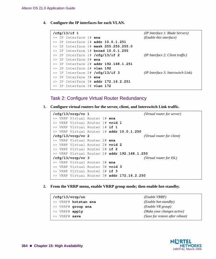
Alteon OS 21.0 Application Guide
4. Configure the IP interfaces for each VLAN.
Task 2: Configure Virtual Router Redundancy
1. Configure virtual routers for the server, client, and Interswitch Link traffic.
2. From the VRRP menu, enable VRRP group mode; then enable hot-standby.
/cfg/l3/if 1 (IP Interface 1: Blade Servers)>> IP Interface 1# ena (Enable this interface)>> IP Interface 1# addr 10.0.1.251>> IP Interface 1# mask 255.255.255.0>> IP Interface 1# broad 10.0.1.255>> IP Interface 1# /cfg/l3/if 2 (IP Interface 2: Client traffic)>> IP Interface 2# ena>> IP Interface 2# addr 192.168.1.251>> IP Interface 2# vlan 192>> IP Interface 2# /cfg/l3/if 3 (IP Interface 3: Interswitch Link)>> IP Interface 3# ena>> IP Interface 3# addr 172.16.2.251>> IP Interface 3# vlan 172
/cfg/l3/vrrp/vr 1 (Virtual router for server)>> VRRP Virtual Router 1# ena>> VRRP Virtual Router 1# vrid 1>> VRRP Virtual Router 1# if 1>> VRRP Virtual Router 1# addr 10.0.1.250/cfg/l3/vrrp/vr 2 (Virtual router for client)>> VRRP Virtual Router 2# ena>> VRRP Virtual Router 2# vrid 2>> VRRP Virtual Router 2# if 2>> VRRP Virtual Router 2# addr 192.168.1.250/cfg/l3/vrrp/vr 3 (Virtual router for ISL)>> VRRP Virtual Router 3# ena>> VRRP Virtual Router 3# vrid 3>> VRRP Virtual Router 3# if 3>> VRRP Virtual Router 3# addr 172.16.2.250
/cfg/l3/vrrp/on (Enable VRRP)>> VRRP# hotstan ena (Enable hot-standby)>> VRRP# group ena (Enable VR group)>> VRRP# apply (Make your changes active)>> VRRP# save (Save for restore after reboot)
364 Chapter 15: High Availability24R9742, March 2006

Alteon OS 21.0 Application Guide
3. Set VRRP tracking for the Interswitch Link ports.
If a link on one of the connected ports goes down, the switch will decrease in VRRP priority and the standby switch will take over as the master.
4. Setup the peer switch (GbESM 2) that will receive synchronization of the Layer 4 config-uration.
Make sure to disable synchronization of VRRP priorities; the peer switch will assume its own priority based on the VRRP election process and should not acquire the VRRP priority from the Master switch’s configuration. If you will be configuring real servers for VRRP hot-standby, make sure to enable synchronization of real server configuration as well.
5. From the SLB menu, enable a hot-standby link on the Layer 4 ports; then enable inter-switch link on the crosslink.
6. Apply and save the changes to the configuration.
/cfg/l3/vrrp/group/ena>> VRRP Virtual Router Group# vrid 1>> VRRP Virtual Router Group# prio 101>> VRRP Virtual Router Group# track>> VRRP Virtual Router Group# ports ena
/cfg/slb/sync/prios d (Do not synchronize VRRP priorities to the peer switch)
>> Config Synchronization# peer 1/ena (Enable the synch. peer switch)>> Peer Switch 1# addr 172.16.2.252 (Set IP address of switch 2)>> Peer Switch 1# /cfg/slb/synch/reals ena (Synchronize real server config to the
peer switch)
/cfg/slb/port INT2>> SLB port INT2# hotstan ena>> SLB port INT2# /cfg/slb/port EXT4>> SLB port EXT4# intersw ena
>> SLB port EXT4# apply>> SLB port EXT4# save
Chapter 15: High Availability 36524R9742, March 2006

Alteon OS 21.0 Application Guide
Task 3: Configure GbESM 2Use the following procedure to dump the configuration script (text dump) from GbESM 1:
1. Begin a Telnet session from the BladeCenter management module.
2. Dump the switch configuration using the following command:
A script will be dumped out.
3. Copy and paste the entire contents of the script to a text file.
The first and last lines of the file should show the following:
4. Edit the text file that you just created as follows:
Change all the IP interface addresses for GbESM 2; otherwise, you will have duplicate IP addresses in the network. In this example, change the last octet in all the IP interfaces from .251 to .252.
Change the synchronization peer switch to use the IP address of GbESM 1. In this exam-ple, change the last octet from .252 (denoting GbESM 2), to .251 (GbESM 1).
5. Save the changes to the text file as “Customer Name” GbESM 2 and load it onto a TFTP server.
/cfg/dump
script start "Nortel Networks Layer2-7 GbE Switch Module" 4 /**** DO NOT EDIT THIS LINE! (File must begin with this line): (All config. commands appear here):script end /**** DO NOT EDIT THIS LINE! (File must end with this line)
(Example from configuration script:)/c/l3/if 1 addr 10.0.1.252
(Example from configuration script:)/c/slb/sync/peer 1 ena addr 172.16.2.251
366 Chapter 15: High Availability24R9742, March 2006

Alteon OS 21.0 Application Guide
Begin a Telnet session for the second switch. Any configuration on it needs to be deleted by resetting it to factory settings, using the following command:
You can tell if the switch is at factory default when you log on because the switch prompts you if you want to use the step-by-step configuration process. When it does, respond: “No.”
6. From the CLI, download the configuration script into the switch from the TFTP server using the following command:
Task 4: Synchronize Layer 4 Parameters from GbESM 1 to GbESM 2
1. On GbESM 1, synchronize the VRRP, SLB, real server, and filter settings to the other switch (same ports).
Switches peering with each other should have an equal number of ports.
2. On GbESM 2, apply and save the configuration changes.
>> Main# /boot/conf factory/reset
/cfg/gtcfg <tftp-server-addr> <cfg-filename>
/oper/slb/sync
NOTE: Use the "/c/slb/sync" menu to configure omitting sections of the configuration.
Synchronizing VRRP, FILT, PORT, REAL and SLB configurationto 172.16.2.252
Confirm synchronizing the configuration to 172.16.2.252 [y/n]:y
Chapter 15: High Availability 36724R9742, March 2006

Alteon OS 21.0 Application Guide
Four-switch configurationThe IBM BladeCenter chassis supports the use of up to four GbE Switch Modules simulta-neously. Combined with VRRP, this provides a massively redundant, highly available solution. With a single VIP, the four switches can be configured to provide Active-Standby-Standby-Standby redundancy. As your application requirements scale, so does your solution. If you have two VIPs, you have an Active-Active, Standby-Standby solution.
This four-switch solution scales all the way to become a full Active-Active-Active-Active solution that provides load-sharing across all of the switch modules. The key is to configure the same VSRs on each of the GbE Switch Modules.
Figure 15-13 on page 369 displays the four-switch configuration, using a four-VIP example. Each GbE Switch Module is the master of a different VIP, and is the standby for the other VIPs. For example, GbE SM 1 master for VIP 1and standby for VIP 2-4, while GbESM 2 is master for VIP 3 and standby for VIP 1, VIP 2, and VIP 4.
368 Chapter 15: High Availability24R9742, March 2006
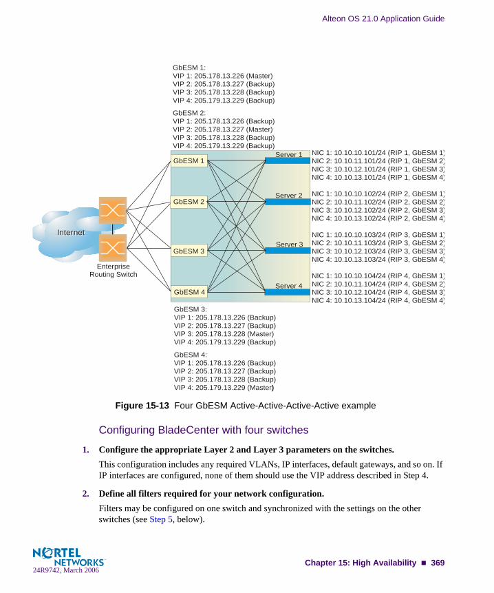
Alteon OS 21.0 Application Guide
Figure 15-13 Four GbESM Active-Active-Active-Active example
Configuring BladeCenter with four switches
1. Configure the appropriate Layer 2 and Layer 3 parameters on the switches.This configuration includes any required VLANs, IP interfaces, default gateways, and so on. If IP interfaces are configured, none of them should use the VIP address described in Step 4.
2. Define all filters required for your network configuration.Filters may be configured on one switch and synchronized with the settings on the other switches (see Step 5, below).
InternetInternet
EnterpriseRouting Switch
GbESM 1
GbESM 2
GbESM 3
GbESM 4
GbESM 1:VIP 1: 205.178.13.226 (Master)VIP 2: 205.178.13.227 (Backup)VIP 3: 205.178.13.228 (Backup)VIP 4: 205.179.13.229 (Backup)
GbESM 2: VIP 1: 205.178.13.226 (Backup)VIP 2: 205.178.13.227 (Master)VIP 3: 205.178.13.228 (Backup)VIP 4: 205.179.13.229 (Backup)
GbESM 3:VIP 1: 205.178.13.226 (Backup)VIP 2: 205.178.13.227 (Backup)VIP 3: 205.178.13.228 (Master)VIP 4: 205.179.13.229 (Backup)
GbESM 4: VIP 1: 205.178.13.226 (Backup)VIP 2: 205.178.13.227 (Backup)VIP 3: 205.178.13.228 (Backup)VIP 4: 205.179.13.229 (Master)
NIC 1: 10.10.10.101/24 (RIP 1, GbESM 1)NIC 2: 10.10.11.101/24 (RIP 1, GbESM 2)NIC 3: 10.10.12.101/24 (RIP 1, GbESM 3)NIC 4: 10.10.13.101/24 (RIP 1, GbESM 4)
NIC 1: 10.10.10.102/24 (RIP 2, GbESM 1)NIC 2: 10.10.11.102/24 (RIP 2, GbESM 2)NIC 3: 10.10.12.102/24 (RIP 2, GbESM 3)NIC 4: 10.10.13.102/24 (RIP 2, GbESM 4)
NIC 1: 10.10.10.103/24 (RIP 3, GbESM 1)NIC 2: 10.10.11.103/24 (RIP 3, GbESM 2)NIC 3: 10.10.12.103/24 (RIP 3, GbESM 3)NIC 4: 10.10.13.103/24 (RIP 3, GbESM 4)
NIC 1: 10.10.10.104/24 (RIP 4, GbESM 1)NIC 2: 10.10.11.104/24 (RIP 4, GbESM 2)NIC 3: 10.10.12.104/24 (RIP 4, GbESM 3)NIC 4: 10.10.13.104/24 (RIP 4, GbESM 4)
Server 1
Server 2
Server 3
Server 4
Chapter 15: High Availability 36924R9742, March 2006

Alteon OS 21.0 Application Guide
3. Configure all required SLB parameters on one of the switches. a. Create real servers:
NOTE – Note: On switches 2-4, use the real IP addresses as shown in Figure 15-13 on page 369.
b. Create SLB Groups.
c. Create the virtual IP addresses.
4. Configure the VRRP parameters on the switch.
>> Main # /cfg/slb/real 1/ena/rip 10.10.10.101(Create real server 1)>> Main # /cfg/slb/real 2/ena/rip 10.10.10.102(Create real server 2)>> Main # /cfg/slb/real 3/ena/rip 10.10.10.103(Create real server 3)>> Main # /cfg/slb/real 4/ena/rip 10.10.10.104(Create real server 4)
>> Main # /cfg/slb/group 1/add 1/add 2/add 3/add 4(Create group 1)>> Main # /cfg/slb/group 2/add 1/add 2/add 3/add 4(Create group 2)>> Main # /cfg/slb/group 3/add 1/add 2/add 3/add 4(Create group 3)>> Main # /cfg/slb/group 4/add 1/add 2/add 3/add 4(Create group 4)
>> Main # /cfg/slb/virt 1/ena/vip 205.178.13.226/ser 80/gr 1(VIP 1)>> Main # /cfg/slb/virt 2/ena/vip 205.178.13.227/ser 80/gr 2(VIP 2)>> Main # /cfg/slb/virt 3/ena/vip 205.178.13.228/ser 80/gr 3(VIP 3)>> Main # /cfg/slb/virt 4/ena/vip 205.178.13.229/ser 80/gr 4(VIP 4)
>> Main # /cfg/l3/vrrp/vr 1/ena/vrid 1/addr 205.178.13.226(VRID 1)>> Main # /cfg/l3/vrrp/vr 2/ena/vrid 2/addr 205.178.13.227(VRID 2)>> Main # /cfg/l3/vrrp/vr 3/ena/vrid 3/addr 205.178.13.228(VRID 3)>> Main # /cfg/l3/vrrp/vr 4/ena/vrid 4/addr 205.178.13.229(VRID 4)>> VRRP Virtual Router 4# apply (Make your changes active)>> VRRP Virtual Router 4# save (Save for restore after reboot)
370 Chapter 15: High Availability24R9742, March 2006

Alteon OS 21.0 Application Guide
5. Create real servers on switch 2 and sync using the “no reals” option.
6. Create real servers on switch 3 and sync using the “no reals” option.
7. Create real servers on switch 4 and sync using the “no reals” option.
>> Main # /cfg/slb/real 1/ena/rip 10.10.11.101(Create real server 1)>> Main # /cfg/slb/real 2/ena/rip 10.10.11.102(Create real server 2)>> Main # /cfg/slb/real 3/ena/rip 10.10.11.103(Create real server 3)>> Main # /cfg/slb/real 4/ena/rip 10.10.11.104(Create real server 4)
>> Main # /oper/slb/sync
>> Main # /cfg/slb/real 1/ena/rip 10.10.12.101(Create real server 1)>> Main # /cfg/slb/real 2/ena/rip 10.10.12.102(Create real server 2)>> Main # /cfg/slb/real 3/ena/rip 10.10.12.103(Create real server 3)>> Main # /cfg/slb/real 4/ena/rip 10.10.12.104(Create real server 4)
>> Main # /oper/slb/sync
>> Main # /cfg/slb/real 1/ena/rip 10.10.13.101(Create real server 1)>> Main # /cfg/slb/real 2/ena/rip 10.10.13.102(Create real server 2)>> Main # /cfg/slb/real 3/ena/rip 10.10.13.103(Create real server 3)>> Main # /cfg/slb/real 4/ena/rip 10.10.13.104(Create real server 4)
>> Main # /oper/slb/sync
Chapter 15: High Availability 37124R9742, March 2006
Alteon OS 21.0 Application Guide
Inter-Chassis Redundancy LinkThe Inter-Chassis Redundancy Link (ICRL) feature allows you to design and build a massively scalable computing grid by providing Application High Availability across multiple Blade-Center chassis. ICRL automates the application fail-over from a failed chassis to a standby chassis. ICRL is enabled by default on the GbE Switch Module.
Multiple ICRL configurations are supported. Two or more BladeCenter chassis with one GbESM each can be configured for Active-Standby redundancy, where one chassis is process-ing the Virtual Server traffic. If you have multiple VIPs, you can utilize an Active-Active con-figuration, to provide load-sharing across both chassis.
To scale your computing grid, install a second GbE Switch Module to each of your Blade-Center chassis and configure the Virtual Servers for which you wish to provide failover. This provides High Availability within the chassis as well across multiple chassis. This topology can be scaled further by adding additional BladeCenters (equipped with GbE Switch Modules) to the design. The key is to configure the same VSR on each of the GbE Switch Modules.
Figure 15-14 on page 373 displays the optimal configuration using a four VIP example. Each GbE Switch Module is the master for a different VIP, and is the standby for each of the others. For example, Chassis 1 GbESM 1 is master for VIP1 and standby for VIP2-4, while Chassis 2 GbESM 1 is master for VIP3 and standby for VIPs 1, 2 and 4. This provides full application availability for any type of failure - application failure, server OS failure, server blade failure, Switch Module failure and chassis failure.
372 Chapter 15: High Availability24R9742, March 2006

Alteon OS 21.0 Application Guide
Figure 15-14 Active-Active Inter-Chassis Redundancy Link example
To implement the example shown in Figure 15-14, configure the switches as follows:
Task 1: Configuring BladeCenter Chassis 1
1. Configure the appropriate Layer 2 and Layer 3 parameters on both switches in chassis 1.This configuration includes any required VLANs, IP interfaces, default gateways, and so on. If IP interfaces are configured, none of them should use the VIP address described in Step 4.
InternetInternet
EnterpriseRouting Switch
VIP 1: 205.178.13.226 (Master)VIP 2: 205.178.13.227 (Backup)VIP 3: 205.178.13.228 (Backup)VIP 4: 205.179.13.229 (Backup)
NIC 1: 10.10.10.104/24 (RIP 4, GbESM 1)NIC 2: 10.10.11.104/24 (RIP 4, GbESM 2)
NIC 1: 10.10.10.101/24 (RIP 1, GbESM 1)NIC 2: 10.10.11.101/24 (RIP 1, GbESM 2)
NIC 1: 10.10.10.102/24 (RIP 2, GbESM 1)NIC 2: 10.10.11.102/24 (RIP 2, GbESM 2)
NIC 1: 10.10.10.103/24 (RIP 3, GbESM 1)NIC 2: 10.10.11.103/24 (RIP 3, GbESM 2)
VIP 1: 205.178.13.226 (Backup)VIP 2: 205.178.13.227 (Master)VIP 3: 205.178.13.228 (Backup)VIP 4: 205.179.13.229 (Backup)
VIP 1: 205.178.13.226 (Backup)VIP 2: 205.178.13.227 (Backup)VIP 3: 205.178.13.228 (Master)VIP 4: 205.179.13.229 (Backup)
NIC 1: 10.10.12.104/24 (RIP 4, GbESM 1)NIC 2: 10.10.13.104/24 (RIP 4, GbESM 2)
NIC 1: 10.10.12.101/24 (RIP 1, GbESM 1)NIC 2: 10.10.13.101/24 (RIP 1, GbESM 2)
NIC 1: 10.10.12.102/24 (RIP 2, GbESM 1)NIC 2: 10.10.13.102/24 (RIP 2, GbESM 2)
NIC 1: 10.10.12.103/24 (RIP 3, GbESM 1)NIC 2: 10.10.13.103/24 (RIP 3, GbESM 2)
VIP 1: 205.178.13.226 (Backup)VIP 2: 205.178.13.227 (Backup)VIP 3: 205.178.13.228 (Backup)VIP 4: 205.179.13.229 (Master)
Chassis 1
Chassis 2
VIP 1: 205.178.13.226 (Master)
VIP 2: 205.178.13.227 (Master)
VIP 3: 205.178.13.228 (Master)
VIP 4: 205.179.13.229 (Master)
Server 1
Server 2
Server 3
Server 4
Server 1
Server 2
Server 3
Server 4
GbESM 1
GbESM 2
GbESM 1
GbESM 2
Chapter 15: High Availability 37324R9742, March 2006

Alteon OS 21.0 Application Guide
2. Define all filters required for your network configuration.Filters may be configured on one switch and synchronized with the settings on the other switch (see Step 5, below).
3. Configure all required SLB parameters on one of the switches. For the purposes of this example, assume that switch 1 in chassis 1 (see Figure 15-14 on page 373) is configured in this step. Required Layer 4 parameters include four virtual IPs (VIP 1 = 205.178.13.226, VIP 2 = 205.178.13.227, VIP3 = 205.178.13.228, VIP 4 = 205.178.13.229) and one real server group with four real servers, RIP1 = 10.10.10.101, RIP2 = 10.10.10.102, RIP3 = 10.10.10.103, and RIP4 = 10.10.10.104. RIP1 = 10.10.11.101 should be configured as a backup server to RIP1 = 10.10.10.101.RIP2 = 10.10.11.102 should be configured as a backup server to RIP2 = 10.10.10.102RIP3 = 10.10.11.103 should be configured as a backup server to RIP3 = 10.10.10.103RIP4 = 10.10.11.104 should be configured as a backup server to RIP4 = 10.10.10.104
NOTE – In this configuration, each server's backup is attached to the other switch. This ensures that operation will continue if all of the servers attached to a switch fail.
4. Configure the VRRP parameters on the switch.Configure VIP 1 address = 205.178.13.226, VRID 1 VIP 2 address =205.178.13.227, VRID 2VIP 3 address=205.178.13.228, VRID 3VIP 4 address=205.178.13.228, VRID 4
5. Synchronize the SLB and VRRP configurations in chassis 1 by pushing the configuration from switch 1 to switch 2.Use the /oper/slb/sync command.
Task 2: Configuring BladeCenter Chassis 2
1. Configure the appropriate Layer 2 and Layer 3 parameters on both switches in chassis 1.This configuration includes any required VLANs, IP interfaces, default gateways, and so on. If IP interfaces are configured, none of them should use the VIP address described in Step 4.
2. Define all filters required for your network configuration.Filters may be configured on one switch and synchronized with the settings on the other switch (see Step 5, below).
374 Chapter 15: High Availability24R9742, March 2006

Alteon OS 21.0 Application Guide
3. Configure all required SLB parameters on one of the switches. For the purposes of this example, assume that switch 1 in chassis 1 (see Figure 15-14 on page 373) is configured in this step. Required Layer 4 parameters include four virtual IPs (VIP 1 = 205.178.13.226, VIP 2 = 205.178.13.227, VIP3 = 205.178.13.228, VIP 4 = 205.178.13.229) and one real server group with four real servers, RIP1 = 10.10.12.101, RIP2 = 10.10.12.102, RIP3 = 10.10.12.103, and RIP4 = 10.10.12.104. RIP1 = 10.10.13.101 should be configured as a backup server to RIP1 = 10.10.12.101.RIP2 = 10.10.13.102 should be configured as a backup server to RIP2 = 10.10.12.102RIP3 = 10.10.13.103 should be configured as a backup server to RIP3 = 10.10.12.103RIP4 = 10.10.13.104 should be configured as a backup server to RIP4 = 10.10.12.104
NOTE – In this configuration, each server's backup is attached to the other switch. This ensures that operation will continue if all of the servers attached to a switch fail.
4. Configure the VRRP parameters on the switch.Configure VIP 1 address = 205.178.13.226, VRID 1 VIP 2 address =205.178.13.227, VRID 2VIP 3 address=205.178.13.228, VRID 3VIP 4 address=205.178.13.228, VRID 4
5. Synchronize the SLB and VRRP configurations in chassis 1 by pushing the configuration from switch 1 to switch 2.Use the /oper/slb/sync command.
Chapter 15: High Availability 37524R9742, March 2006

Alteon OS 21.0 Application Guide
Layer 2 Trunk Failover with VRRPYou can combine Layer 2 Trunk Failover with VRRP, which allows you to scale High Avail-ability to multiple levels:
NIC failover within a chassis
Virtual Server Routers across multiple BladeCenter chassis
When the VRRP Trunk Failover command (/cfg/l3/vrrp/trnkfo) is enabled, you can configure Layer 2 Trunk Failover when VRRP is enabled.
NOTE – When Layer 2 Trunk Failover is enabled, you cannot enable VRRP Hot Standby.
376 Chapter 15: High Availability24R9742, March 2006

Alteon OS 21.0 Application Guide
Figure 15-15 Active-Active Configuration with L2 Trunk Failover
In this configuration, you set up virtual servers similar to the configuration described in “Active-Active Server Load Balancing Configuration” on page 353. Then you configure Layer 2 Trunk Failover similar to the configuration described in “Layer 2 Trunk Failover” on page 326.
For example, Chassis 1 is the Master for HTTP service, and Backup for FTP service. Chassis 2 is the Master for FTP service, and Backup for HTTP service. Within each chassis, GbESM 2 is the Backup for GbESM 1. All ingress traffic flows to GbESM 1.
EnterpriseRouting Switch
InternetInternet
EnterpriseRouting Switch
L2 trunk failoveris enabled for switch failoverin a chassis
Chassis 2
VIP 1: 205.178.13.221 (Backup)VIP 2: 205.178.13.222 (Master)Priority = 100
VIP 1: 205.178.13.221 (Master)VIP 2: 205.178.13.222 (Backup)Priority = 101
VIP 1: 205.178.13.221 (Backup)VIP 2: 205.178.13.222 (Master)Priority = 100
VIP 1: 205.178.13.221 (Master)VIP 2: 205.178.13.222 (Backup)Priority = 101
10.10.10.101/24 (RIP 1)
10.10.10.102/24 (RIP 2)
10.10.10.103/24 (RIP 3)
Chassis 1
GbESM 1
GbESM 2
Server 1
Server 2
Server 3
GbESM 1
GbESM 2
Server 1
Server 2
Server 3
10.10.10.104/24 (RIP 1)
10.10.10.105/24 (RIP 2)
10.10.10.106/24 (RIP 3)
= active link= standby link
Chapter 15: High Availability 37724R9742, March 2006

Alteon OS 21.0 Application Guide
Failover ScenariosWithin a chassis, if all links to GbESM 1 fail, then the server NICs failover to GbESM 2.
There are three possible failover scenarios between the BladeCenter chassis:
A chassis shuts down.
All uplinks between both GbESMs in a chassis and the Layer 2 switch fail.
A server blade within a chassis is removed.
In the first two scenarios, the switches in chassis 2 stop receiving VRRP advertisements from chassis 1. One of the GbESMs in chassis 2 is elected to become the Master for VIP 1.
If a server blade is removed from chassis 1, the priority of the switches in chassis 1 changes from 107 (101 + 6) to 105 (101 + 4). Since the priority of the switches in chassis 2 is 106 (100 + 6), one of them is elected to become the Master for VIP 1.
Task 1: Configuring BladeCenter Chassis 1
1. Configure the appropriate Layer 2 and Layer 3 parameters on both switches in chassis 1.This configuration includes any required VLANs, IP interfaces, default gateways, and Layer 2 Trunk Failover. If IP interfaces are configured, none of them should use the VIP address described in Step 4.
2. Define all filters required for your network configuration.Filters may be configured on one switch and synchronized with the settings on the other switch (see Step 5, below).
3. Configure all required SLB parameters on GbESM 1. For the purposes of this example, assume that GbESM 1 in chassis 1 (see Figure 15-15 on page 377) is configured in this step. Required Layer 4 parameters include two virtual IPs: (VIP 1 = 205.178.13.221, VIP 2 = 205.178.13.222), and one real server group with three real servers: RIP1 = 10.10.10.101, RIP2 = 10.10.10.102, RIP3 = 10.10.10.103
NOTE – In this configuration, NIC Teaming is configured to ensure that failover occurs when the active NIC fails.
4. Configure the VRRP parameters on GbESM 1. Configure VIP 1 address = 205.178.13.221, VRID 1 VIP 2 address =205.178.13.222, VRID 2 Priority = 101VRRP Trunk Failover enabled
378 Chapter 15: High Availability24R9742, March 2006
Alteon OS 21.0 Application Guide
5. Synchronize the SLB and VRRP configurations in chassis 1 by pushing the configuration from GbESM 1 to GbESM 2.Use the /oper/slb/sync command, with real servers enabled and priority disabled.
Task 2: Configuring BladeCenter Chassis 2
1. Configure the appropriate Layer 2 and Layer 3 parameters on both switches in chassis 1.This configuration includes any required VLANs, IP interfaces, default gateways, and Layer 2 Trunk Failover. If IP interfaces are configured, none of them should use the VIP address described in Step 4.
2. Define all filters required for your network configuration.Filters may be configured on one switch and synchronized with the settings on the other switch (see Step 5, below).
3. Configure all required SLB parameters on GbESM 1. For the purposes of this example, assume that GbESM 1 in chassis 1 (see Figure 15-15 on page 377) is configured in this step. Required Layer 4 parameters include two virtual IPs: (VIP 1 = 205.178.13.221, VIP 2 = 205.178.13.221), and one real server group with three real servers: RIP1 = 10.10.12.101, RIP2 = 10.10.12.102, RIP3 = 10.10.12.103
NOTE – In this configuration, NIC Teaming is configured to ensure that failover occurs when the active NIC fails.
4. Configure the VRRP parameters on GbESM 1. Configure VIP 1 address = 205.178.13.221, VRID 1 VIP 2 address =205.178.13.222, VRID 2Priority = 100VRRP Trunk Failover enabled
5. Synchronize the SLB and VRRP configurations in chassis 1 by pushing the configuration from GbESM 1 to GbESM 2.Use the /oper/slb/sync command, with real servers enabled and priority disabled.
6. Change the VRRP renter priority of GbESM 2 to 101.
Chapter 15: High Availability 37924R9742, March 2006

Alteon OS 21.0 Application Guide
380 Chapter 15: High Availability24R9742, March 2006

Part 4: Advanced Switching
Alteon OS can parse requests and classify flows using URLs, host tags, and cookies so that each request can be isolated and treated intelligently. This section describes the following advanced switching applications:
Content Intelligent Switching
Persistence
24R9742, March 2006

Alteon OS 21.0 Application Guide
382 : Advanced Switching24R9742, March 2006

CHAPTER 16Content Intelligent Switching
This chapter discusses advanced load balancing solutions utilizing Layer 7 content switching. Inspecting HTTP headers, examining content identifiers such as URLs and cookies, and pars-ing content requests are discussed in the following topics:
“Overview” on page 384
“Content Intelligent Server Load Balancing” on page 387
“Content Intelligent Cache Redirection” on page 405
“Exclusionary String Matching for Real Servers” on page 421
“Regular Expression Matching” on page 423
“Content Precedence Lookup” on page 425
“Layer 7 Deny Filters” on page 428
NOTE – For all content-intelligent switching features enable Direct Access Mode (DAM) or configure proxy IP addresses.
24R9742, March 2006383

Alteon OS 21.0 Application Guide
OverviewGbE Switch Modules perform content intelligent switching by processing numerous tasks for each incoming session, including connection setup, traffic parsing, applying server selection algorithms, splicing connections and translating session addresses, metering and controlling server bandwidth usage, processing traffic filters, collecting statistics, and so on. Figure 16-1 illustrates the process of content intelligent switching in the GbE Switch Module.
Figure 16-1 Content Intelligent Load Balancing Example
InternetInternet
GbE Switch ModuleGbE Switch Module
GbE Switch ModuleGbE Switch Module
GbE Switch ModuleGbE Switch Module
GbESM
384 Chapter 16: Content Intelligent Switching24R9742, March 2006

Alteon OS 21.0 Application Guide
Parsing ContentExamining session content places heavier demands upon the switch than examining TCP/IP headers for the following reasons:
Content is non-deterministic. Content identifiers such as URLs and cookies can be of varying lengths and can appear at unpredictable locations within a request. Scanning ses-sion traffic for a specific string is far more processor-intensive than looking at a known location in a session for a specific number of bytes.
To parse a content request, the switch must temporarily terminate the TCP connection from the client. This temporary termination is called a delayed binding. While the connec-tion is suspended, the switch acknowledges the client connection on behalf of the server, buffers and examines the client request, and finally opens a connection to an appropriate server based on the requested content.
For more information on delayed binding, see “Delayed Binding” on page 200.
Delayed binding causes two independent TCP connections to span a Web session: one from the client to the switch and the second from the switch to the selected server. The switch must modify the TCP header, including performing TCP sequence number transla-tion and recalculating checksums on every packet that travels between the client and the server, for the duration of the session. This function, known as TCP connection splicing, heavily tasks a switch, particularly when the switch must process thousands of these ses-sions simultaneously.
In addition to real-time traffic and connection processing, a content intelligent switch must monitor servers to ensure that requests are forwarded to the best-performing and healthiest servers. This monitoring involves more than simple ICMP or TCP connection tests, as servers can continue to process network protocols while failing to retrieve content.
If content is segregated in different servers or server farms, the switch must provide a flex-ible, user-customizable mechanism allowing a relevant set of application and content tests to be applied to each server or server farm.
In addition to implementing content intelligent switching, the switch periodically performs background functions such as updating network topology, measuring server performance, and health checking for servers, applications, and server sites.
HTTP Header InspectionContent intelligent switching is performed by inspecting HTTP headers. HTTP headers include additional information about requests and responses. The HTTP 1.1 specification defines a total of 46 headers. For cache redirection, at any given time one HTTP header is sup-ported globally for the entire switch.
Chapter 16: Content Intelligent Switching 38524R9742, March 2006
Alteon OS 21.0 Application Guide
HTTP headers can be general, request, response, or entity headers. General headers may exist in both requests and responses. Requests and response headers are specific only to requests and responses, respectively. Entity headers describe the content of the request body or the content of the response body.
Each HTTP header field consists of a name, followed immediately by a colon ( : ), a single space character, and the field value. Field names are case-insensitive. Header fields can be extended over multiple lines by preceding each extra line with at least one space.
Some customer applications of HTTP header inspection are listed below:
Redirection based on domain nameCachability based on domain nameVirtual hostingRedirection based on browser typeCookie-based preferential redirection
Buffering Content with Multiple FramesTo handle the overall length of HTTP headers, including request headers containing multiple cookies, and the Maximum Segment Size (MSS) of dial-up connections, Alteon OS software provides the following support:
HTTP GET Request Headers
NOTE – In addition to the URL path, which generally is less than 300 bytes, the HTTP GET requests also include general headers and request headers.
Parsing GET requests to match URL path and HTTP header beyond the first frame while performing delayed binding
Processing multiple frames from a single HTTP GET request, using a TCP stack on the switch
HTTP Cookie Request Headers
Buffering a maximum of 4500 bytes for a single GET request across multiple frames. A single GET request can include multiple cookies.
386 Chapter 16: Content Intelligent Switching24R9742, March 2006
Alteon OS 21.0 Application Guide
Content Intelligent Server Load BalancingAlteon OS allows you to load balance HTTP requests based on different HTTP header infor-mation, such as “Cookie:” header for persistent load balancing, “Host:” header for virtual host-ing, or “User-Agent” for browser-smart load balancing.
URL-Based Server Load Balancing on this page
“Virtual Hosting” on page 392
“Cookie-Based Preferential Load Balancing” on page 395
“URL Hashing for Server Load Balancing” on page 399
“Header Hash Load Balancing” on page 401
“DNS Load Balancing” on page 402
URL-Based Server Load BalancingURL-based SLB allows you to optimize resource access and server performance. Content dis-persion can be optimized by making load-balancing decisions on the entire path and filename of each URL.
NOTE – Both HTTP 1.0 and HTTP 1.1 requests are supported.
For URL matching you can configure up to 512 strings comprised of 40 bytes each. Each URL request is then examined against the URL strings defined for each real server. URL requests are load balanced among multiple servers matching the URL, according to the load balancing metric configured for the real server group (leastConns is the default).
In Figure 16-2, the following criteria are specified for content load balancing:
Requests with “.cgi” in the URL are forwarded to real servers 3 and 4.Requests with the string “images” in the URL are sent to real servers 1 and 2.Requests with URLs starting with “/product:” are sent to real servers 2, 3, and 5.
Requests containing URLs with anything else are sent to real servers 1, 2, 3, and 4. These serv-ers have been defined with the “any” string.
Chapter 16: Content Intelligent Switching 38724R9742, March 2006

Alteon OS 21.0 Application Guide
Figure 16-2 URL-Based Server Load Balancing
Configuring URL-Based Server Load BalancingTo configure URL-based SLB, perform the following steps:
1. Before you can configure URL-based load balancing, ensure that the switch has already been configured for basic SLB with the following tasks:
NOTE – When URL-based SLB is used in an active/active redundant setup, use a proxy IP address instead of Direct Access Mode (DAM) to enable the URL parsing feature.
Assign an IP address to each of the real servers in the server pool.Define an IP interface on the switch.Define each real server.Define a real server group and set up health checks for the group.Define a virtual server on virtual port 80 (HTTP), and assign the real server group to service it.Enable SLB on the switch.Enable client processing on the port connected to the clients.
For information on how to configure your network for SLB, see “Server Load Balancing” on page 171.
GbESM
388 Chapter 16: Content Intelligent Switching24R9742, March 2006

Alteon OS 21.0 Application Guide
2. Define the string(s) to be used for URL load balancing.
add: Add string or a path.rem: Remove string or a path.
A default string “any” indicates that the particular server can handle all URL or cache requests. Refer to the following examples given below:
Example 1: String with the Forward Slash (/)
A string that starts with a forward slash ( / ), such as “/images,” indicates that the server will process requests that start out with the “/images” string only.
For example, with the “/images” string, the server will handle these requests:
/images/product/b.gif/images/company/a.gif/images/testing/c.jpg
The server will not handle these requests:
/company/images/b.gif/product/images/c.gif/testing/images/a.gif
Example 2: String without the Forward Slash (/)
A string that does not start out with a forward slash ( / ) indicates that the server will process any requests that contain the defined string. For example, with the “images” string, the server will process these requests:
/images/product/b.gif/images/company/a.gif/images/testing/c.jpg/company/images/b.gif/product/images/c.gif/testing/images/a.gif
Example 3: String with the Forward Slash (/) Only
If a server is configured with the load balance string ( / ) only, it will only handle requests to the root directory. For example, the server will handle any files in the root directory:
//index.htm/default.asp/index.shtm
>> # /cfg/slb/layer7/slb/add|rem <string>
Chapter 16: Content Intelligent Switching 38924R9742, March 2006

Alteon OS 21.0 Application Guide
3. Apply and save your configuration changes.
4. Identify the defined string IDs.
For easy configuration and identification, each defined string is assigned an ID number, as shown in the following example:
5. Configure one or more real servers to support URL-based load balancing.
6. Add the defined string(s) to the real server using the following command:
where ID is the identification number of the defined string.
NOTE – If you don't add a defined string (or add the defined string “any”) the server will han-dle any request.
A server can have multiple defined strings. For example:
“/images”“/sales”“.gif”
With these defined strings, this particular server can handle requests that start with “/images” or “/sales” and any requests that contain “.gif”.
7. Enable SLB on the switch.
>> # /cfg/slb/layer7/slb/cur
ID SLB String1 any
2 .gif
3 /sales
4 /xitami
5 /manual
6 .jpg
>> # /cfg/slb/real 2/layer7/addlb <ID>
>> # /cfg/slb/on (Turn SLB on)
390 Chapter 16: Content Intelligent Switching24R9742, March 2006

Alteon OS 21.0 Application Guide
8. Enable DAM on the switch or configure proxy IP addresses and enable proxy on the cli-ent port.
DAM and proxy IPs allow you to perform port mapping for URL load balancing.
Enable DAM
Configure a proxy IP address and enable proxy on the client port
For more information on proxy IP addresses, see “Proxy IP Addresses” on page 190.
9. Enable URL-based SLB on the virtual server(s).
Statistics for URL-Based Server Load BalancingTo show the number of hits to the SLB or cache server, use this command:
Sample Statistics:
>> # /cfg/slb/adv/direct ena
>> # /cfg/slb/adv/direct dis>> # /cfg/slb/pip>> Proxy IP Address# pip1 12.12.12.12>> # /cfg/slb/port 2/proxy ena
>> # /cfg/slb/virt <virtual server number>/service 80/httpslb urlslb
>> # /stats/slb/layer7/str
ID SLB String Hits
1 any 73881
2 .gif 0
3 /sales 0
4 /xitami 162102
5 /manual 0
6 .jpg 0
Chapter 16: Content Intelligent Switching 39124R9742, March 2006
Alteon OS 21.0 Application Guide
Virtual HostingAlteon OS allows individuals and companies to have a presence on the Internet in the form of a dedicated Web site address. For example, you can have a “www.site-a.com” and “www.site-b.com” instead of “www.hostsite.com/site-a” and “www.hostsite.com/site-b.”
Service providers, on the other hand, do not want to deplete the pool of unique IP addresses by dedicating an individual IP address for each home page they host. By supporting an extension in HTTP 1.1 to include the host header, Alteon OS enables service providers to create a single vir-tual server IP address to host multiple Web sites per customer, each with their own host name.
NOTE – For SLB, one HTTP header is supported per virtual server.
The following list provides more detail on virtual hosting with configuration information.
An HTTP/1.0 request sent to an origin server (not a proxy server) is a partial URL instead of a full URL.
An example of the request that the origin server would see as follows:
GET /products/2224/ HTTP/1.0User-agent: Mozilla/3.0Accept: text/html, image/gif, image/jpeg
The GET request does not include the host name. From the TCP/IP headers, the origin server knows the requests host name, port number, and protocol.
With the extension to HTTP/1.1 to include the HTTP HOST: header, the above request to retrieve the URL “/www.nortelnetworks.com/ products/2224” would look like this:
GET /products/2224/ HTTP/1.1Host: www.nortelnetworks.comUser-agent: Mozilla/3.0Accept: text/html, image/gif, image/jpeg
The Host: header carries the hostname used to generate the IP address of the site.
Based on the Host: header, the switch will forward the request to servers representing dif-ferent customers’ Web sites.
The network administrator needs to define a domain name as part of the 128 supported URL strings.
The switch performs string matching; that is, the string “nortelnetworks.com” or “www.nortelnetworks.com” will match “www.nortelnetworks.com.”
392 Chapter 16: Content Intelligent Switching24R9742, March 2006

Alteon OS 21.0 Application Guide
Virtual Hosting Configuration OverviewThe sequence of events for configuring virtual hosting based on HTTP Host: headers is described below:
1. The network administrator defines a domain name as part of the 128 supported URL strings.
Both domain names “www.company-a.com” and “www.company-b.com” resolve to the same IP address. In this example, the IP address is for a virtual server on the switch.
2. “www.company-a.com” and “www.company-b.com” are defined as URL strings.
3. Server Group 1 is configured with Servers 1 through 8.
Servers 1 through 4 belong to “www.company-a.com” and Servers 5 through 8 belong to “www.company-b.com.”
4. The network administrator assigns string “www.company-a.com” to Servers 1 through 4 and string “www.company-b.com” to Servers 5 through 8.
5. The switch inspects the HTTP host header in requests received from the client.
If the host header is “www.company-a.com,” the switch directs requests to one of the Servers 1 through 4.
If the host header is “www.company-b.com,” the switch directs requests to one of the Servers 5 through 8.
Chapter 16: Content Intelligent Switching 39324R9742, March 2006

Alteon OS 21.0 Application Guide
Configuring the “Host” Header for Virtual HostingTo support virtual hosting, configure the switch for Host header-based load balancing with the following procedure:
1. Before you can configure host header-based server load balancing, ensure that the switch has already been configured for basic SLB:
Assign an IP address to each of the real servers in the server pool.Define an IP interface on the switch.Define each real server.Assign servers to real server groups.Define virtual servers and services.
For information on how to configure your network for server load balancing, see “Server Load Balancing” on page 171.
2. Turn on URL parsing for the virtual server for virtual hosting.
3. Define the host names.
4. Configure the real server(s) to handle the appropriate load balancing string(s).
To add a defined string:
where ID is the identification number of the defined string.
NOTE – If you don't add a defined string (or add the defined string “any”), the server will han-dle any request.
>> # /cfg/slb/virt 1 (Select the virtual IP for host header-based SLB)
>> Virtual Server 1 # service 80 (Select the HTTP service)>> Virtual Server 1 http Service # httpslb host
>> # /cfg/slb/layer7/slb/add "www.customer1.com">> Server Loadbalance Resource# add "www.customer2.com">> Server Loadbalance Resource# add "www.customer3.com"
>> # /cfg/slb/real 2 (Select the real server)>> Real Server 2 # Layer7>> Real Server 2 Layer 7 Commands # addlb <ID>(Specify the string ID)
394 Chapter 16: Content Intelligent Switching24R9742, March 2006

Alteon OS 21.0 Application Guide
Cookie-Based Preferential Load BalancingCookies can be used to provide preferential services for customers, ensuring that certain users are offered better access to resources than other users when site resources are scarce. For example, a Web server could authenticate a user via a password and then set cookies to identify them as “Gold,” “Silver,” or “Bronze” customers. Using cookies, you can distinguish individu-als or groups of users and place them into groups or communities that get redirected to better resources and receive better services than all other users.
NOTE – Cookie-based persistent load balancing is described in Chapter 17, “Persistence.”
Cookie-based preferential services enable the following support:
Redirect higher priority users to a larger server or server group.Identify a user group and redirect them to a particular server.Serve content based on user identity.Prioritize access to scarce resources on a Web site.Provide better services to repeat customers, based on access count.
Clients that receive preferential service can be distinguished from other users by one of the fol-lowing methods:
Individual User
Specific individual user could be distinguished by IP address, login authentication, or per-manent HTTP cookie.
User Communities
Some set of users, such as “Premium Users” for service providers who pay higher mem-bership fees than “Normal Users” could be identified by source address range, login authentication, or permanent HTTP cookie.
Applications
Users could be identified by the specific application they are using. For example, priority can be given to HTTPS traffic that is performing credit card transactions versus HTTP browsing traffic.
Content
Users could be identified by the specific content they are accessing.
Based on one or more of the criteria above, you can load balance requests to different server groups.
Chapter 16: Content Intelligent Switching 39524R9742, March 2006

Alteon OS 21.0 Application Guide
Configuring Cookie-Based Preferential Load BalancingTo configure cookie-based preferential load balancing, perform the following procedure.
1. Before you can configure header-based load balancing, ensure that the switch has already been configured for basic SLB with the following tasks:
Assign an IP address to each of the real servers in the server pool.Define an IP interface on the switch.Define each real server.Assign servers to real server groups.Define virtual servers and services.
For information on how to configure your network for SLB, see Chapter 10, “Server Load Bal-ancing.
2. Turn on URL parsing for the virtual server.
where
sid = cookie name1 = offset (the starting position of the value to be used for hashing)6 = length (the number of bytes in the cookie value)d = looks for the cookie in the cookie header instead of the URI (disables searching for cookie in the URI)
3. Define the cookie values.
Since a session cookie does not exist in the first request of an HTTP session, a default server or “any” server is needed to assign cookies to a “None” cookie HTTP request.
>> # /cfg/slb/virt 1>> Virtual Server 1 # service 80>> Virtual Server 1 http Service # httpslb cookieEnter Cookie Name: sid Enter the starting point of the Cookie value [1-64]: 1Enter the number of bytes to extract [1-64]: 6Look for Cookie in URI [e|d]: d
>> # /cfg/slb/layer7/slb/add "Gold">> # add "Silver">> # add "Bronze"
396 Chapter 16: Content Intelligent Switching24R9742, March 2006
Alteon OS 21.0 Application Guide
Example:
Real Server 1: “Gold” handles gold requests.Real Server 2: “Silver” handles silver request.Real Server 3: “Bronze” handles bronze request.Real Server 4: “any” handles any request that does not have a cookie or matching cookie.
With servers defined to handle the requests listed above, here is what happens:
Request 1 comes in with no cookie; it is forwarded to Real Server 4 to get cookie assigned.Request 2 comes in with “Gold” cookie; it will be forwarded to Real Server 1.Request 3 comes in with “Silver” cookie; it will be forwarded to Real Server 2.Request 4 comes in with “Bronze” cookie; it will be forwarded to Real Server 3.Request 5 comes in with “Titanium” cookie; it will be forwarded to Real Server 4, since it does not have an exact cookie match (matches with “any” configured at Real Server 4).
4. Configure the real server(s) to handle the appropriate load balance string(s).
To add a defined string:
where ID is the identification number of the defined string.
NOTE – If you don't add a defined string (or add the defined string “any”), the server will han-dle any request.
5. Enable DAM on the switch or configure proxy IP addresses and enable proxy on the cli-ent port.
To use cookie-based preferential load balancing without DAM, you must configure proxy IP addresses.
Enable proxy load balancing on the port used for cookie-based preferential load balancing. If Virtual Matrix Architecture (VMA) is enabled on the switch, you can choose to configure the remaining ports with proxy IP disabled.
>> # /cfg/slb/real 2/layer7/addlb <ID>
Chapter 16: Content Intelligent Switching 39724R9742, March 2006

Alteon OS 21.0 Application Guide
Browser-Smart Load BalancingHTTP requests can be directed to different servers based on browser type by inspecting the “User-Agent” header. For example,
GET /products/2224/ HTTP/1.0User-agent: Mozilla/3.0Accept: text/html, image/gif, image/jpeg
To allow the switch to perform browser-smart load balancing, perform the following proce-dure.
1. Before you can configure browser-based load balancing, ensure that the switch has already been configured for basic SLB with the following tasks:
Assign an IP address to each of the real servers in the server pool.Define an IP interface on the switch.Define each real server.Assign servers to real server groups.Define virtual servers and services.
2. Turn on URL parsing for the virtual server for “User-Agent:” header.
3. Define the host names.
4. Configure the real server(s) to handle the appropriate load balancing string(s).
NOTE – If you don't add a defined string (or add the defined string “any”), the server will han-dle any request.
Use the following command to add a defined string:
where ID is the identification number of the defined string.
>> # /cfg/slb/virt 1/service 80/httpslb browser
>> # /cfg/slb/layer7/slb/add "Mozilla">> Server Loadbalance Resource# add "Internet Explorer">> Server Loadbalance Resource# add "Netscape"
>> # /cfg/slb/real 2/layer7/addlb <ID>
398 Chapter 16: Content Intelligent Switching24R9742, March 2006

Alteon OS 21.0 Application Guide
URL Hashing for Server Load BalancingBy default, hashing algorithms use the IP source address and/or IP destination address (depending on the application area) to determine content location. The default hashing algo-rithm for SLB is the IP source address. By enabling URL hashing, requests going to the same page of an origin server are redirected to the same real server or cache server.
Load Balancing of Nontransparent CachesYou can deploy a cluster of non-transparent caches and use the virtual server to load balance requests to the cache servers. The client’s browser is configured to send Web requests to a non-transparent cache (the IP address of the configured virtual server).
If hash is selected as the load-balancing algorithm, the switch hashes the source IP address to select the server for SLB. Under this condition, the switch may not send requests for the same origin server to the same proxy cache server. For example, requests made from a client to “http://www.nortelnetworks.com/products” from different clients may get sent to different caches.
Figure 16-3 Balancing Nontransparent Caches
Configuring URL HashingYou can direct the same URL request to the same cache or proxy server by using a virtual server IP address to load balance proxy requests. By configuring hash or minmisses as the metric, the switch uses the number of bytes in the URI to calculate the hash key.
If the host field exists and the switch is configured to look into the Host: header, the switch uses the Host: header field to calculate the hash key.
Non-TransparentCache FarmNon-TransparentCache Farm
GbESM
Chapter 16: Content Intelligent Switching 39924R9742, March 2006

Alteon OS 21.0 Application Guide
To configure URL hashing, perform the following procedure:
1. Before you can configure URL hashing, ensure that the switch has already been config-ured for basic SLB with the following tasks:
Assign an IP address to each of the real servers in the server pool.Define an IP interface on the switch.Define each real server.Assign servers to real server groups.Define virtual servers and services.Configure load-balancing algorithm for hash or minmiss.Enable SLB.
For information on how to configure your network for SLB, see Chapter 10, “Server Load Balancing.”
Define server port and client port.
2. Enable URL hashing.
Hashing is based on the URL, including the HTTP Host: header (if present), up to a maximum of 255 bytes.
3. Set the metric for the real server group to minmisses or hash.
>> # /cfg/slb/virt 1>> Virtual Server 1 # service 80>> Virtual Server 1 http Service # httpslb urlhashEnter new hash length [1-255]: 25
>> # /cfg/slb/group 1/metric <hash|minmisses>
400 Chapter 16: Content Intelligent Switching24R9742, March 2006

Alteon OS 21.0 Application Guide
Header Hash Load BalancingAlteon OS allows you to hash on any selected HTTP header. To configure the GbE Switch Module for load balancing based on header hash, perform the following procedure:
1. Ensure that the switch has already been configured for basic SLB:
Assign an IP address to each of the real servers in the server pool.Define an IP interface on the switch.Define each real server.Assign servers to real server groups.Define virtual servers and services.
For information on how to configure your network for SLB, see Chapter 10, “Server Load Bal-ancing.”
2. Enable header hashing.
3. Set the metric for the real server group to minmisses or hash.
>> # /cfg/slb/virt 1>> Virtual Server 1 # service 80>> Virtual Server 1 http Service # httpslb headerhashSelect Operation: noneEnter new HTTP header name: User-agentEnter new hash length [1-255]: 25
>> # /cfg/slb/group 1/metric <hash|minmisses>
Chapter 16: Content Intelligent Switching 40124R9742, March 2006

Alteon OS 21.0 Application Guide
DNS Load BalancingThe Internet name registry has become so large that a single server cannot keep track of all the entries. This is resolved by splitting the registry and saving it on different servers.
If you have large DNS server farms, Alteon OS allows you to load balance traffic based on DNS names. To load balance DNS names, the host name is extracted from the query, processed by the regular expressions engine, and the request is sent to the appropriate real server.
For example, Figure 16-4 shows a DNS server farm load balancing DNS queries based on DNS names. Requests with DNS names beginning with A through G are sent to Server 1; DNS names beginning with H through M are sent to Server 2; DNS names beginning with N through T are sent to Server 3; DNS names beginning with U through Z are sent to Server 4.
Figure 16-4 Load Balancing DNS Queries
Server 1
Server 3
Server 2
Server 4
DNS Server Farm
DNS queries A-G
DNS queries H-M
DNS queries N-T
DNS queries U-Z
GbESM
402 Chapter 16: Content Intelligent Switching24R9742, March 2006

Alteon OS 21.0 Application Guide
To configure the switch for DNS load balancing, perform the following procedure:
1. Before you can configure DNS load balancing, ensure that the switch has already been configured for basic SLB with the following tasks:
Assign an IP address to each of the real servers in the server pool.Define an IP interface on the switch.Define each real server (DNS server address).Assign servers to real server groups.Define virtual servers and services.Enable SLB.
For information on how to configure your network for SLB, see Chapter 10, “Server Load Balancing.”
Define server port and client port.
2. Enable DNS load balancing.
3. Enable delayed binding.
4. Define the host names.
5. Apply and save your configuration changes.
>> # /cfg/slb/virt 1 (Select the virtual server)>> Virtual Server 1 # service 53 (Select the DNS service)>> Virtual Server 1 DNS Service # dnsslb ena(Enable DNS SLB)
>> Virtual Server 1 DNS Service# dbind ena
>> # /cfg/slb/layer7/slb/add www.[abcdefg]*.com>> Server Loadbalance Resource# add www.[hijklm]*.com>> Server Loadbalance Resource# add www.[nopqrst]*.com>> Server Loadbalance Resource# add www.[uvwxyz]*.com
Chapter 16: Content Intelligent Switching 40324R9742, March 2006

Alteon OS 21.0 Application Guide
6. Identify the defined string IDs.
For easy configuration and identification, each defined string has an ID attached, as shown in the following example:
7. Add the defined string IDs to the real server using the following command:
NOTE – If you don't add a defined string (or add the defined string “any”) the server will han-dle any request.
>> # /cfg/slb/layer7/slb/cur
ID SLB String1 any, cont 1024
2 www.[abcdefg]*.com, cont 1024
3 www.[hijklm]*.com, cont 1024
4 www.[nopqrst]*.com, cont 1024
5 www.[uvwxyz]*.com, cont 1024
>> # /cfg/slb/real 1/layer7/addlb 2>> # /cfg/slb/real 2/layer7/addlb 3>> # /cfg/slb/real 3/layer7/addlb 4
404 Chapter 16: Content Intelligent Switching24R9742, March 2006
Alteon OS 21.0 Application Guide
Content Intelligent Cache RedirectionAlteon OS allows you to redirect cache requests based on different HTTP header information, such as “Host:” header or “User-Agent” for browser-smart load balancing. For more information on layer 4 cache redirection, see Chapter 13, “Application Redirection.”
The No Cache/Cache Control for cache redirection feature in Alteon OS allows you to off load the processing of non-cacheable content from cache servers by sending only appropriate requests to the cache server farm. When a Cache-Control header is present in a HTTP 1.1 request, it indicates a client's special request with respect to caching, such as to guarantee up-to-date data from the origin server. If this feature (Cache-Control: no cache directive) is enabled, HTTP 1.1 GET requests are forwarded directly to the origin servers.
NOTE – The term origin server refers to the server originally specified in the request.
The HTTP 1.0 Pragma: no-cache header is equivalent to the HTTP 1.1 Cache-Con-trol header. By enabling the Pragma: no-cache header, requests are forwarded to the ori-gin server.
NOTE – For cache redirection, at any given time one HTTP header is supported globally for the entire switch.
This section discusses the following types of cache redirection:
“URL-Based Cache Redirection” on page 406
“HTTP Header-Based Cache Redirection” on page 415
“Browser-Based Cache Redirection” on page 416
“URL Hashing for Cache Redirection” on page 417
Chapter 16: Content Intelligent Switching 40524R9742, March 2006
Alteon OS 21.0 Application Guide
URL-Based Cache RedirectionURL parsing for cache redirection operates in a manner similar to URL-based server load bal-ancing except that in cache redirection a virtual server on the switch is the target of all IP/HTTP requests. For information on URL-based server load balancing, see “URL-Based Server Load Balancing” on page 387.
By separating static and dynamic content requests via URL parsing, Alteon OS enables you to send requests with specific URLs or URL strings to designated cache servers. The URL-based cache redirection option allows you to off load overhead processing from the cache servers by only sending appropriate requests to the cache server farm.
NOTE – Both HTTP 1.0 and HTTP 1.1 requests are supported.
Each request is examined and handled as described below:
If the request is a non-GET request such as HEAD, POST, PUT, or HTTP with cookies, it is not sent to the cache.
If the request is an ASP or CGI request or a dynamically generated page, it is not sent to the cache.
If the request contains a Cookie, it can optionally bypass the cache.
Examples of matching string expressions are:
/product
Any URL that starts with “/product,” including any information in the “/product” direc-tory
product
Any URL that has the string “product”
406 Chapter 16: Content Intelligent Switching24R9742, March 2006

Alteon OS 21.0 Application Guide
Some of the common noncacheable items that you can configure the switch to add to, delete, or modify are:
Dynamic content files:Common gateway interface files (.cgi)cold fusion files (.cfm), ASP files (.asp)BIN directoryCGI-BIN directorySHTML (scripted html)Microsoft HTML extension files (.htx)executable files (.exe)
Dynamic URL parameters: +, !, %, =, &
Chapter 16: Content Intelligent Switching 40724R9742, March 2006

Alteon OS 21.0 Application Guide
Figure 16-5 URL-Based Cache Redirection
Requests matching the URL are load balanced among the multiple servers, depending on the metric specified for the real server group (leastconns is the default).
InternetInternetN
on-H
TT
P G
ET
GET/www.hostc.com/cgi-bin/script.bin
GET/http://finance.yahoo.com/q?s=hwp%2c+ibm%d=v1
$GET/product/Webswitch.html
GET/company/images/switch.gif
$$
Implicit load balancingwithin the group
images
/productinformation
GbESM
408 Chapter 16: Content Intelligent Switching24R9742, March 2006
Alteon OS 21.0 Application Guide
Network Address Translation OptionsURL-based cache redirection supports three types of Network Address Translation (NAT): No NAT, Half NAT, and Full NAT.
No NAT
In this NAT method, the traffic is redirected to the cache with the destination MAC address of the virtual server replaced by the MAC address of the cache. The destination IP address remains unchanged, and no modifications are made to the IP address or the MAC address of the source or origin server. This works well for transparent cache servers, which process traffic destined to their MAC address but use the IP address of some other device.
Half NAT
In this most commonly used NAT method, the destination IP address is replaced by the IP address of the cache, and the destination MAC address is replaced by the MAC address of the cache. Both the IP address and the MAC address of the source remain unchanged.
Full NAT
In this NAT method, the source IP address and the source MAC address are replaced by the IP address and MAC address of the cache. This method works well for proxy cache servers.
Configuring URL-Based Cache RedirectionTo configure URL-based cache redirection, perform the following steps:
1. Before you can configure URL-based cache redirection, configure the switch for basic Server Load Balancing (SLB) with the following tasks:
Assign an IP address to each of the real servers in the server pool.Define an IP interface on the switch.Define each real server.
For information on how to configure your network for SLB, see “Server Load Balancing” on page 171.
2. Configure the switch to support basic cache redirection.
For information on cache redirection, refer to “Application Redirection” on page 287.
Chapter 16: Content Intelligent Switching 40924R9742, March 2006

Alteon OS 21.0 Application Guide
3. Configure the parameters and file extensions that bypass cache redirection.
a) Add or remove string IDs that should not be cacheable.
b) Enable/disable ALLOW for non-GETS (such as HEAD, POST, and PUT) to the ori-gin server, as described below.
Ena: The switch allows all non-GET requests to the origin server.
Dis: The switch compares all requests against the expression table to determine whether the request should be redirected to a cache server or the origin server.
c) Enable/disable cache redirection of requests that contain “cookie:” in the HTTPheader.
Ena: The switch redirects all requests that contain “cookie:” in the HTTP header to the origin server.
Dis: The switch compares the URL against the expression table to determine whether the request should be redirected to a cache server or the origin server.
d) Enable/disable cache redirection of requests that contain “Cache-control:no cache” in the HTTP 1.1 header or “Pragma:no cache” in the HTTP 1.0 header to the origin server.
Ena: The switch redirects all requests that contain Cache-control: no cache in the HTTP 1.1 header or Pragma:no cache in the HTTP 1.0 header to the origin server.
Dis: The switch compares the URL against the expression table to determine whether the request should be redirected to a cache server or the origin server.
>> # /cfg/slb/filt 1/adv/addstr|remstr <ID>>> # /cfg/slb/layer7/slb/add|remove <strings>
>> # /cfg/slb/layer7/redir/urlal ena|dis
>> # /cfg/slb/layer7/redir/cookie ena|dis
>> # /cfg/slb/layer7/redir/nocache ena|dis
410 Chapter 16: Content Intelligent Switching24R9742, March 2006

Alteon OS 21.0 Application Guide
4. Define the string(s) to be used for cache SLB. Refer to the parameters listed below:
add: Add a string or a path.rem: Remove string or a path.
A default string “any” indicates that the particular server can handle all URL or cache requests. Refer to the following examples:
Example 1: String Starting with the Forwardslash (/)
A string that starts with a forwardslash ( / ), such as “/images,” indicates that the server will process requests that start out with the “/images” string only.
For example, with the “/images” string, the server will handle these requests:
/images/product/b.gif/images/company/a.gif/images/testing/c.jpg
The server will not handle these requests:
/company/images/b.gif/product/images/c.gif/testing/images/a.gif
Example 2: String without the Forwardslash (/)
A string that does not start out with a forwardslash ( / ) indicates that the server will process any requests that contain the defined string. For example, with the “images” string, the server will process these requests:
/images/product/b.gif/images/company/a.gif/images/testing/c.jpg/company/images/b.gif/product/images/c.gif/testing/images/a.gif
Example 3: String with the Forwardslash (/) Only
If a server is configured with the load balance string ( / ) only, it will only handle requests to the root directory. For example, the server will handle any files in the ROOT directory:
//index.htm/default.asp/index.shtm
>> # /cfg/slb/layer7/slb/add|rem <string>
Chapter 16: Content Intelligent Switching 41124R9742, March 2006

Alteon OS 21.0 Application Guide
5. Apply and save your configuration changes.
6. Identify the defined string IDs.
For easy configuration and identification, each defined string has an ID attached, as shown in the following example:
7. Configure the real server(s) to support cache redirection.
NOTE – If you don't add a defined string (or add the defined string “any”), the server will han-dle any request.
Add the defined string(s) to the real servers:
where ID is the identification number of the defined string.
The server can have multiple defined strings. For example: “/images”, “/sales”, “.gif”
With these defined strings, the server can handle requests that begin with “/images” or “/sales” and any requests that contain “.gif”.
8. Define a real server group and add real servers to the group.
The following configuration combines three real servers into a group:
>> # /cfg/slb/layer7/slb/cur
ID SLB String1 any
2 .gif
3 /sales
4 /xitami
5 /manual
6 .jpg
>> # /cfg/slb/real 2/layer7/addlb <ID>
>> # /cfg/slb/group 1 (Select real server group 1)>> Real server group 1# add 1 (Add real server 1 to group 1)>> Real server group 1# add 2 (Add real server 2 to group 1)>> Real server group 1# add 3 (Add real server 3 to group 1)
412 Chapter 16: Content Intelligent Switching24R9742, March 2006

Alteon OS 21.0 Application Guide
9. Configure a filter to support basic cache redirection.
The filter must be able to intercept all TCP traffic for the HTTP destination port and must redi-rect it to the proper port in the real server group:
10. Enable URL-based cache redirection on the same filter.
11. Select the appropriate NAT option.
The three NAT options are listed below. For more information about each option, see “Net-work Address Translation Options” on page 409.
No NAT option:
Half NAT option:
Full NAT option:
For more information on proxy IP addresses, see “Proxy IP Addresses” on page 190.
>> # /cfg/slb/filt <filter number> (Select the menu for Filter #x)>> Filter <filter number># sip any (From any source IP addresses)>> Filter <filter number># dip any (To any destination IP addresses)>> Filter <filter number># proto tcp (For TCP protocol traffic)>> Filter <filter number># sport any (From any source port)>> Filter <filter number># dport http (To an HTTP destination port)>> Filter <filter number># action redir (Set the action for redirection)>> Filter <filter number># rport http (Set the redirection port)>> Filter <filter number># group 1 (Select real server group 1)>> Filter <filter number># ena (Enable the filter)
>> # /cfg/slb/filt <filter number>/adv/urlp ena
>> # /cfg/slb/filter <filter number>/adv/proxy dis
>> # /cfg/slb/filter <filter number>/adv/proxy ena
>> # /cfg/slb/pip >> Proxy IP Address# pip1 12.12.12.12 (Configure proxy IP address)>> # /cfg/slb/filt <filter number>>> Filter <filter number># rport 3128 (Specify redirection port)>> Filter <filter number># adv (Select the advance menu)>> Filter <filter number> Advanced# proxy ena(Enable proxy IP address)
Chapter 16: Content Intelligent Switching 41324R9742, March 2006
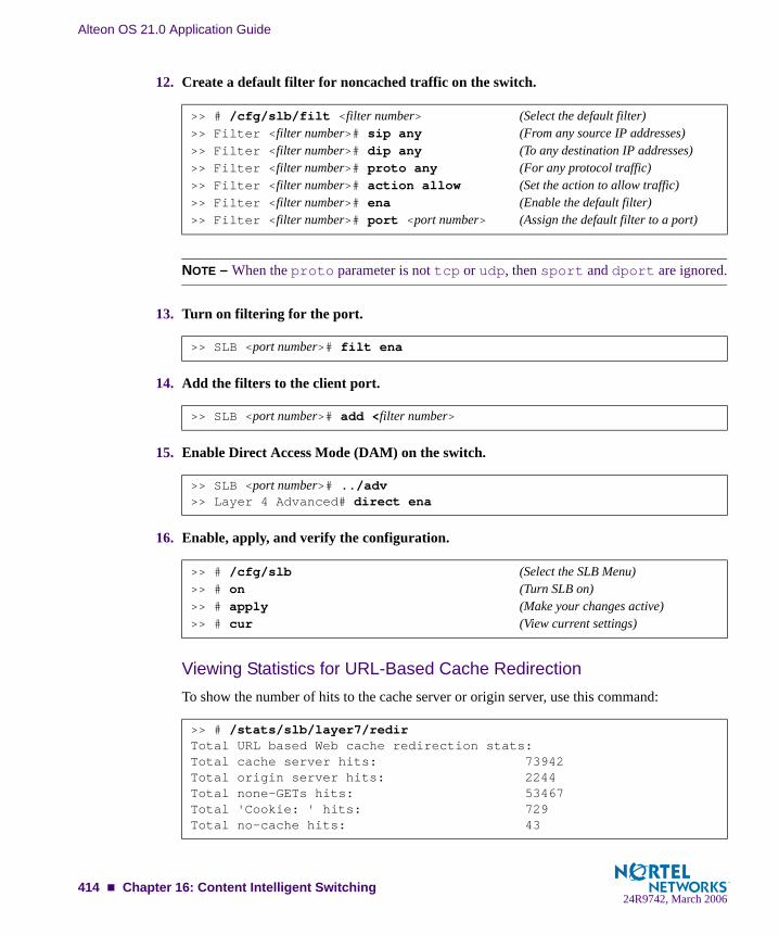
Alteon OS 21.0 Application Guide
12. Create a default filter for noncached traffic on the switch.
NOTE – When the proto parameter is not tcp or udp, then sport and dport are ignored.
13. Turn on filtering for the port.
14. Add the filters to the client port.
15. Enable Direct Access Mode (DAM) on the switch.
16. Enable, apply, and verify the configuration.
Viewing Statistics for URL-Based Cache RedirectionTo show the number of hits to the cache server or origin server, use this command:
>> # /cfg/slb/filt <filter number> (Select the default filter)>> Filter <filter number># sip any (From any source IP addresses)>> Filter <filter number># dip any (To any destination IP addresses)>> Filter <filter number># proto any (For any protocol traffic)>> Filter <filter number># action allow (Set the action to allow traffic)>> Filter <filter number># ena (Enable the default filter)>> Filter <filter number># port <port number> (Assign the default filter to a port)
>> SLB <port number># filt ena
>> SLB <port number># add <filter number>
>> SLB <port number># ../adv>> Layer 4 Advanced# direct ena
>> # /cfg/slb (Select the SLB Menu)>> # on (Turn SLB on)>> # apply (Make your changes active)>> # cur (View current settings)
>> # /stats/slb/layer7/redirTotal URL based Web cache redirection stats:Total cache server hits: 73942Total origin server hits: 2244Total none-GETs hits: 53467Total 'Cookie: ' hits: 729Total no-cache hits: 43
414 Chapter 16: Content Intelligent Switching24R9742, March 2006

Alteon OS 21.0 Application Guide
HTTP Header-Based Cache RedirectionTo configure the switch for cache direction based on the “Host:” header, use the following pro-cedure:
1. Configure basic SLB.
Before you can configure header-based cache redirection, ensure that the switch has already been configured for basic SLB (see “Server Load Balancing” on page 171) with the following tasks:
Assign an IP address to each of the real servers in the server pool.Define an IP interface on the switch.Define each real server.Assign servers to real server groups.Define virtual servers and services.
2. Turn on URL parsing for the filter.
3. Enable header load balancing for the Host: header.
4. Define the host names.
5. Apply and save your configuration changes.
6. Identify the string ID numbers with this command.
Each defined string has an associated ID number.
>> # /cfg/slb/filt 1/adv/urlp ena
>> # /cfg/slb/layer7/redir/header ena host
>> # /cfg/slb/layer7/slb/add ".com">> Server Load Balance Resource# add ".org">> Server Load Balance Resource# add ".net"
>> # /cfg/slb/layer7/slb/cur
ID SLB String1 any
2 .com
3 .org
4 .net
Chapter 16: Content Intelligent Switching 41524R9742, March 2006

Alteon OS 21.0 Application Guide
7. Configure the real server(s) to handle the appropriate load balance string(s).
Add the defined string IDs to the real servers:
where ID is the identification number of the defined string.
NOTE – If you don’t add a defined string (or add ID=1), the server will handle any request.
Browser-Based Cache RedirectionBrowser-based cache redirection uses the User-agent: header. To configure browser-based cache redirection, perform the following procedure.
1. Before you can configure header-based cache redirection, ensure that the switch is already configured for basic SLB with the following tasks:
Assign an IP address to each of the real servers in the server pool.Define an IP interface on the switch.Define each real server.Assign servers to real server groups.Define virtual servers and services.
2. Turn on URL parsing for the filter.
3. Enable header load balancing for “User-Agent:” header.
4. Define the host names.
5. Apply and save your configuration changes.
>> # /cfg/slb/real 2/layer7/addlb <ID>
>> # /cfg/slb/filt 1/adv/urlp enable
>> # /cfg/slb/layer7/redir/header ena useragent
>> # /cfg/slb/layer7/slb/add "Mozilla">> Server Load Balance Resource# add "Internet Explorer">> Server Load Balance Resource# add "Netscape"
416 Chapter 16: Content Intelligent Switching24R9742, March 2006

Alteon OS 21.0 Application Guide
6. Identify the string ID numbers with this command.
Each defined string has an ID number.
Number of entries: four
7. Add the defined string IDs to configure the real server(s) to handle the appropriate load balance string(s).
where ID is the identification number of the defined string.
NOTE – If you don't add a defined string (or add the ID 1), the server will handle any request.
URL Hashing for Cache RedirectionBy default, hashing algorithms use the source IP address and/or destination IP address (depending on the application area) to determine content location. For example, firewall load balancing uses both source and destination IP addresses, cache redirection uses only the desti-nation IP address, and SLB uses only the source IP address.
Hashing is based on the URL, including the HTTP Host header (if present), up to a maximum of 255 bytes. You can optimize “cache hits” by using the hashing algorithm to redirect client requests going to the same page of an origin server to a specific cache server.
For example the switch could use the string “nortelnetworks.com/products/2224/” for hashing the following request:
GET http://products/2224/ HTTP/1.0HOST:www.nortelnetworks.com
>> # /cfg/slb/layer7/slb/cur
ID SLB String1 any
2 Mozilla
3 Internet Explorer
4 Netscape
>> # /cfg/slb/real 2/layer7/addlb <ID>
Chapter 16: Content Intelligent Switching 41724R9742, March 2006
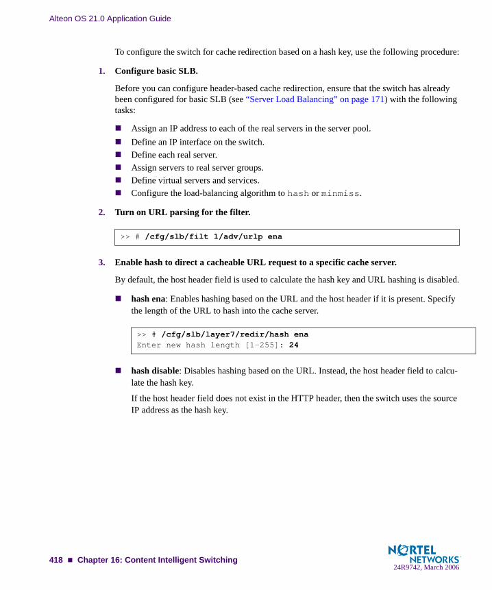
Alteon OS 21.0 Application Guide
To configure the switch for cache redirection based on a hash key, use the following procedure:
1. Configure basic SLB.
Before you can configure header-based cache redirection, ensure that the switch has already been configured for basic SLB (see “Server Load Balancing” on page 171) with the following tasks:
Assign an IP address to each of the real servers in the server pool.Define an IP interface on the switch.Define each real server.Assign servers to real server groups.Define virtual servers and services.Configure the load-balancing algorithm to hash or minmiss.
2. Turn on URL parsing for the filter.
3. Enable hash to direct a cacheable URL request to a specific cache server.
By default, the host header field is used to calculate the hash key and URL hashing is disabled.
hash ena: Enables hashing based on the URL and the host header if it is present. Specify the length of the URL to hash into the cache server.
hash disable: Disables hashing based on the URL. Instead, the host header field to calcu-late the hash key.
If the host header field does not exist in the HTTP header, then the switch uses the source IP address as the hash key.
>> # /cfg/slb/filt 1/adv/urlp ena
>> # /cfg/slb/layer7/redir/hash enaEnter new hash length [1-255]: 24
418 Chapter 16: Content Intelligent Switching24R9742, March 2006

Alteon OS 21.0 Application Guide
Example 1: Hashing on the URLIn this example, URL hashing is enabled. If the Host field does not exist, the specified length of the URL is used to hash into the cache server as shown in Figure 16-6 on page 419. If the Host field exists, the specified length of both the Host field and the URL is used to hash into the cache server. The same URL request goes to the same cache server as shown below:
Client 1 request http://www.nortelnetworks.com/sales/index.htm is directed to cache server 1.Client 2 request http://www.nortelnetworks.com/sales/index.htm is directed to cache server 1.Client 3 request http://www.nortelnetworks.com/sales/index.htm is directed to cache server 1.
Figure 16-6 URL Hashing for Application Redirection
Example 2: Hashing on the Host Header Field OnlyIn this example, URL hashing is disabled. If you use the Host header field to calculate the hash key, the same URL request goes to the same cache server:
Client 1 request http://www.nortelnetworks.com is directed to cache server 1.Client 2 request http://www.nortelnetworks.com is directed to cache server 1.Client 3 request http://www.nortelnetworks.com is directed to cache server 1.
InternetInternet
123
BladeCenter
Chapter 16: Content Intelligent Switching 41924R9742, March 2006
Alteon OS 21.0 Application Guide
Example 3: Hashing on the Source IP addressIn this example, URL hashing is disabled. Because the host header field does not exist in the HTTP header, the source IP address is used as the hash key and requests from clients 1, 2, and 3 are directed to three different cache servers as shown below.
Client 1 request http://www.nortelnetworks.com is directed to cache server 1.Client 2 request http://www.nortelnetworks.com is directed to cache server 2.Client 3 request http://www.nortelnetworks.com is directed to cache server 3.
420 Chapter 16: Content Intelligent Switching24R9742, March 2006

Alteon OS 21.0 Application Guide
Exclusionary String Matching for Real ServersURL-based SLB and application redirection can match or exclude up to 128 strings. Examples of strings are as follows:
“/product,” matches URLs that starts with /product.“product,” matches URLs that have the string “product” anywhere in the URL.
You can assign one or more strings to each real server. When more than one URL string is assigned to a real server, requests matching any string are redirected to that real server. There is also a special string known as “any” that matches all content.
Alteon OS also supports exclusionary string matching. Using this option, you can define a server to accept any requests regardless of the URL, except requests with a specific string.
NOTE – Once exclusionary string matching is enabled, clients cannot access the URL strings that are added to that real server. This means you cannot configure a dedicated server to receive a certain string and, at the same time, have it exclude other URL strings. The exclu-sionary feature is enabled per server, not per string.
For example, the following strings are assigned to a real server:string 1 = cgistring 2 = NOT cgi/form_Astring 3 = NOT cgi/form_B
As a result, all cgi scripts are matched except form_A and form_B.
Configuring for Exclusionary URL String MatchingThis configuration example shows you how to configure a server to handle any requests except requests that contain the string “test” or requests that start with “/images” or “/product”.
To configure exclusionary URL string matching, perform the following procedure:
1. Before you can configure URL string matching, ensure that the switch has already been configured for basic SLB:
Assign an IP address to each of the real servers in the server pool.Define an IP interface on the switch.Define each real server.Assign servers to real server groups.Define virtual servers and services.Enable SLB.
Chapter 16: Content Intelligent Switching 42124R9742, March 2006

Alteon OS 21.0 Application Guide
For information on how to configure your network for server load balancing, see Chapter 10, “Server Load Balancing.”
2. Add the load balancing strings (for example test, /images, and /product) to the real server.
3. Apply and save the configuration.
4. Identify the IDs of the defined strings.
5. Assign the URL string ID to the real server.
6. Enable the exclusionary string matching option.
If you configured a string “any” and enabled the exclusion option, the server will not handle any requests. This has the same effect as disabling the server.
>> # /cfg/slb/layer7/slb/add test>> Server Loadbalance Resource# add “/images”>> Server Loadbalance Resource# add “/product”
>> Server Loadbalance Resource# cur
ID SLB String1 any
2 test
3 /images
4 /product
>> Real Server 1 Layer 7 commands# addlb 2>> Real Server 1 Layer 7 commands# addlb 3>> Real Server 1 Layer 7 commands# addlb 4
>> Real Server 1 Layer 7 commands# exclude enable
422 Chapter 16: Content Intelligent Switching24R9742, March 2006

Alteon OS 21.0 Application Guide
Regular Expression MatchingRegular expressions are used to describe patterns for string matching. They enable you to match the exact string, such as URLs, host names, or IP addresses. It is a powerful and effec-tive way to express complex rules for Layer 7 string matching. Both Layer 7 HTTP SLB and cache redirection can use regular expressions as a resource. Configuring for regular expres-sions can enhance content-based switching in the following areas:
HTTP header matching
URL matching
Standard Regular Expression CharactersThe following is a list of standard regular expression special characters that are supported in Alteon OS:
Use the following rules to describe patterns for string matching:
Supports one layer of parenthesis.
Supports only single “$” (match at end of line) which must appear at the end of the string. For example, “abc$*def” is not supported.
Size of the user input string must be 40 characters or less.
Table 16-1 Standard Regular Expression Special Characters
Construction Description
* Matches any string of zero or more characters
. Matches any single character
+ Matches one or more occurrences of the pattern it follows
? Matches zero or one occurrences of its followed pattern
$ Matches the end of a line
\ Escape the following special character
[abc] Matches any of the single character inside the bracket
[^abc] Matches any single character except those inside the bracket
Chapter 16: Content Intelligent Switching 42324R9742, March 2006

Alteon OS 21.0 Application Guide
Size of the regular expression structure after compilation cannot exceed 43 bytes for load balancing strings and 23 bytes for cache redirection. The size of regular expression after compilation varies, based on regular expression characters used in the user input string.
Use “/” at the beginning of the regular expression. Otherwise a regular expression will have “*” prefixed to it automatically. For example, “html/*\.htm” appears as “*html/*\.htm”.
Incorrectly or ambiguously formatted regular expressions are rejected instantly. For example:
where a “+” or “?” follows a special character like the “*”
A single “+” or “?” sign
Unbalanced brackets and parenthesis
Configuring Regular ExpressionsThe regular expression feature is applicable to both path strings used for URL-based server load balancing, and expression strings used for URL-based application redirection. Configure regular expressions at the following CLI prompts:
or
As a result, both HTTP SLB and application redirection can use regular expression as the resource.
NOTE – The more complex the structure of the string, the longer it will take for the server to load balance the incoming packets.
/cfg/slb/layer7/slb/add
/cfg/slb/layer7/slb/redir/add
424 Chapter 16: Content Intelligent Switching24R9742, March 2006

Alteon OS 21.0 Application Guide
Content Precedence LookupThe Layer 7 Precedence Lookup feature in Alteon OS allows you to give precedence to one Layer 7 parameter over another and selectively decide which parameter should be analyzed first.
The Content Precedence Lookup feature allows you to combine up to two Layer 7 load balanc-ing mechanisms. You can specify which types of Layer 7 content to examine, the order in which they are examined, and a logical operator (and/or) for their evaluation.The following Layer 7 content types can be specified:
URL SLBHTTP HostCookieBrowsers (User agent)URL hashHeader hash
Using the above content types with the and and or operators, the switch is configured to refine HTTP-based server load balancing multiple times on a single client HTTP request in order to bind it to an appropriate server. Typically, when you combine two content types with an opera-tor (and/or), URL hash and Header hash are used in combination with Host, Cookie, or Browser content types. For example, the following types of load balancing can be configured using the Content Precedence Lookup feature:
Virtual host and/or URL-based load balancingCookie persistence and URL-based load balancingCookie load balancing and/or URL-based load balancingCookie persistence and HTTP SLB together in the same serviceMultiple HTTP SLB process type on the same service
NOTE – Cookie persistence can also be combined with the Layer 7 content types. For more information on cookie persistence, see Chapter 17, “Persistence.”
For example, the Content Precedence Lookup feature can be used in the following scenarios:
If the client request is sent without a cookie and if no HTTP SLB is configured, then the switch binds the request to the real server using normal SLB.If the client request is sent without a cookie, but HTTP SLB is configured on the switch, then the request is bound to real server based on HTTP SLB.
If the client request is sent with a cookie, and a real server associated to the cookie is found in the local session table, then the request will stay bound to that real server.
Chapter 16: Content Intelligent Switching 42524R9742, March 2006

Alteon OS 21.0 Application Guide
RequirementsEnable Direct Access Mode (DAM), or configure proxy IP address if DAM is disabled.Enable delayed binding.
Using the or and and OperatorsFigure 16-7 shows a network with real servers 1 and 3 configured for URL SLB and real serv-ers 2 and 3 configured for HTTP Host SLB.
Figure 16-7 Content Precedence Lookup Protectors Example
If the Content Precedence Lookup feature is configured with the or and and operators, the request from the client is as follows:
HTTP Host or URL SLBThe HTTP Host header takes precedence because it is specified first. If there is no Host Header information and because or is the operator, the URL string is examined next.
If a request from a client contains no Host Header but has a URL string (such as “/gold”), the request is load balanced among Server 1 or Server 3.If a request from a client contains a Host Header, then the request is load balanced among Server 2 and Server 3. The URL string is ignored because the HTTP Host was specified and matched first.
InternetInternet 1
23
GbESM
426 Chapter 16: Content Intelligent Switching24R9742, March 2006
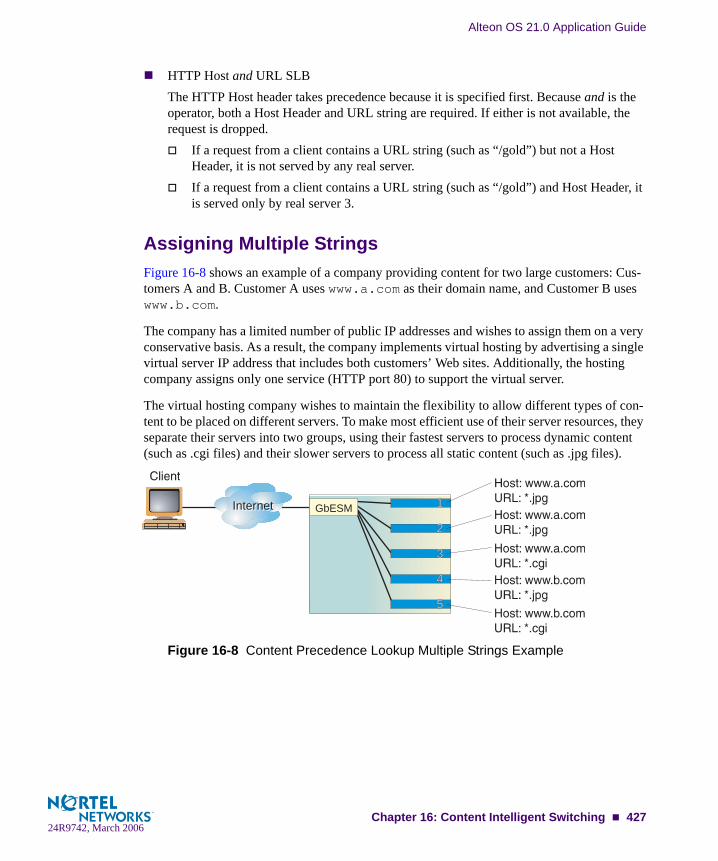
Alteon OS 21.0 Application Guide
HTTP Host and URL SLBThe HTTP Host header takes precedence because it is specified first. Because and is the operator, both a Host Header and URL string are required. If either is not available, the request is dropped.
If a request from a client contains a URL string (such as “/gold”) but not a Host Header, it is not served by any real server.If a request from a client contains a URL string (such as “/gold”) and Host Header, it is served only by real server 3.
Assigning Multiple StringsFigure 16-8 shows an example of a company providing content for two large customers: Cus-tomers A and B. Customer A uses www.a.com as their domain name, and Customer B uses www.b.com.
The company has a limited number of public IP addresses and wishes to assign them on a very conservative basis. As a result, the company implements virtual hosting by advertising a single virtual server IP address that includes both customers’ Web sites. Additionally, the hosting company assigns only one service (HTTP port 80) to support the virtual server.
The virtual hosting company wishes to maintain the flexibility to allow different types of con-tent to be placed on different servers. To make most efficient use of their server resources, they separate their servers into two groups, using their fastest servers to process dynamic content (such as .cgi files) and their slower servers to process all static content (such as .jpg files).
Figure 16-8 Content Precedence Lookup Multiple Strings Example
InternetInternet 1
2
3
4
5
GbESM
Chapter 16: Content Intelligent Switching 42724R9742, March 2006

Alteon OS 21.0 Application Guide
To configure content precedence lookup for the example in Figure 16-8, the hosting company groups all the real servers into one real server group even though different servers provide ser-vices for different customers and different types of content. In this case, the servers are set up for the following purpose:
When a client request is received with www.a.com in the Host Header and .jpg in the URL, the request will be load balanced between Server 1 and Server 2.
To accomplish this configuration, you must assign multiple strings (a Host Header string and a URL string) for each real server.
Layer 7 Deny FiltersAlteon OS allows you to secure your switch from virus attacks by configuring the switch with a list of potential offending string patterns (HTTP URL request). The switch examines the HTTP content of the incoming client request for the matching string pattern. If the matching virus pattern is found, then the packet is dropped and a reset frame is sent to the offending cli-ent. SYSLOG messages and SNMP traps are generated warning operators of a possible attack.
A layer 7 deny filter is basically a deny filter except that the deny action is delayed until HTTP content is examined to see if the packet should be denied.
Table 16-2 Real Server Content
Server Customer Content
Server 1 Customer A Static .jpg files
Server 2 Customer A Static .jpg files
Server 3 Customer A Dynamic .cgi files
Server 4 Customer B Static .jpg files
Server 5 Customer B Dynamic .cgi files
428 Chapter 16: Content Intelligent Switching24R9742, March 2006

Alteon OS 21.0 Application Guide
Figure 16-9 shows an incoming client request with a virus string. The switch is configured for Layer 7 deny filter, so it blocks the incoming packet with the virus string and prevents it from entering the network.
Figure 16-9 Configuring Layer 7 Deny Filter
Configuring a Layer 7 Deny Filter
1. Before you can configure Layer 7 deny filter, ensure that the switch has already been con-figured for basic switch functions:
Assign an IP address to each of the real servers in the server pool.Define an IP interface on the switch.
For information on how to configure your network for the above tasks, see Chapter 10, “Server Load Balancing.”
2. Define the virus string patterns or offending HTTP URL request to be blocked.
3. Apply and save the configuration.
>> # /cfg/slb/layer7/slb/add ida (Define the code red virus string)>> Server Loadbalance resource# add %c1%9c (Define the code blue virus string)>> Server Loadbalance resource# add %c0%af(Define the code blue virus string)>> Server Loadbalance resource# add playdog.com(Define the offending URL
request)
11
5
2
3
4
InternetInternet GbESM Servers
Chapter 16: Content Intelligent Switching 42924R9742, March 2006

Alteon OS 21.0 Application Guide
4. Identify the IDs of the defined strings.
Number of entries: four
5. Assign the URL string ID from Step 4 to the filter.
6. Select the filter and enable the filter action to deny.
7. Enable the Layer 7 deny option.
8. Apply and save the configuration.
9. Apply the filter to the client port.
If the incoming client requests are on port 3, then add the filter to the port.
>> Server Loadbalance resource# cur
ID SLB String1 ida
2 %c1%9c
3 %c0%af
4 playdog.com
>> Filter 1 Advanced L7deny# addstr 1 (Add the code red virus string)>> Filter 1 Advanced L7deny# addstr 2 (Add the code blue virus string)>> Filter 1 Advanced L7deny# addstr 3 (Add the code blue virus string)>> Filter 1 Advanced L7deny# addstr 4 (Add the offending URL request)
>> # /cfg/slb/filt 1 (Select the filter)>> Filter 1 # action deny (Set the filter action to deny)
>> Filter 1 Advanced# l7deny ena (Enable the Layer 7 deny filter)
>> # /cfg/slb/port 3 (Select the client port)>> SLB Port 3# filt ena (Enable filtering on the port)>> SLB Port 3# add 1 (Add the Layer 7 filter to the port)
430 Chapter 16: Content Intelligent Switching24R9742, March 2006
CHAPTER 17Persistence
The Alteon OS persistence feature ensures that all connections from a specific client session reach the same real server, even when Server Load Balancing (SLB) is used.
The following topics are addressed in this chapter:
“Overview of Persistence” on page 432. This section gives an overview of persistence and the different types of persistence methods implemented in Alteon OS.
“Cookie-Based Persistence” on page 434. The use of cookie persistence provides a mech-anism for inserting a unique key for each client of a virtual server. This feature is only used in nonsecure socket layer (non-SSL) connections. This section discusses in detail how persistence is maintained between a client and a real server using different types of cookies.
“Server-Side Multi-Response Cookie Search” on page 447. This section explains how to configure the switch to look through multiple HTTP responses from the server to achieve cookie-based persistence.
“SSL Session ID-Based Persistence” on page 448. This section explains how an applica-tion server and client communicate over an encrypted HTTP session.
“Windows Terminal Server Load Balancing and Persistence” on page 450. This section explains how to configure load balancing and persistence for Windows Terminal Services
24R9742, March 2006431
Alteon OS 21.0 Application Guide
Overview of PersistenceIn a typical SLB environment, traffic comes from various client networks across the Internet to the virtual server IP address on the GbE Switch Module. The switch then load balances this traffic among the available real servers.
In any authenticated Web-based application, it is necessary to provide a persistent connection between a client and the content server to which it is connected. Because HTTP does not carry any state information for these applications, it is important for the browser to be mapped to the same real server for each HTTP request until the transaction is complete. This ensures that the client traffic is not load balanced mid-session to a different real server, forcing the user to restart the entire transaction.
Persistence-based SLB enables the network administrator to configure the network to redirect requests from a client to the same real server that initially handled the request. Persistence is an important consideration for administrators of e-commerce Web sites, where a server may have data associated with a specific user that is not dynamically shared with other servers at the site.
In Alteon OS, persistence can be based on the following characteristics: source IP address, cookies, and Secure Sockets Layer (SSL) session ID.
Using Source IP AddressUntil recently, the only way to achieve TCP/IP session persistence was to use the source IP address as the key identifier. There are two major conditions which cause problems when ses-sion persistence is based on a packet’s IP source address:
Many clients sharing the same source IP address (proxied clients): Proxied clients appear to the switch as a single source IP address and do not take advantage of SLB on the switch. When many individual clients behind a firewall use the same proxied source IP address, requests are directed to the same server, without the benefit of load balancing the traffic across multiple servers. Persistence is supported without the capability of effec-tively distributing traffic load.
Also, persistence is broken if you have multiple proxy servers behind the switch perform-ing SLB. The switch changes the client’s address to different proxy addresses as attempts are made to load balance client requests.
Single client sharing a pool of source IP addresses: When individual clients share a pool of source IP addresses, persistence for any given request cannot be assured. Although each source IP address is directed to a specific server, the source IP address itself is ran-domly selected, thereby making it impossible to predict which server will receive the request. SLB is supported, but without persistence for any given client.
432 Chapter 17: Persistence24R9742, March 2006
Alteon OS 21.0 Application Guide
Using CookiesCookies are strings passed via HTTP from servers to browsers. Based on the mode of opera-tion, cookies are inserted by either the switch or the server. After a client receives a cookie, a server can poll that cookie with a GET command, which allows the querying server to posi-tively identify the client as the one that received the cookie earlier.
The cookie-based persistence feature solves the proxy server problem and gives better load distribution at the server site. In the switch, cookies are used to route client traffic back to the same physical server to maintain session persistence.
Using SSL Session IDThe SSL session ID is effective only when the server is running SSL transactions. Because of the heavy processing load required to maintain SSL connections most network configurations use SSL only when it is necessary. Persistence based on SSL Session ID ensures completion of complex transactions in proxy server environments. However, this type of persistence does not scale on servers because of their computational requirements.
Chapter 17: Persistence 43324R9742, March 2006

Alteon OS 21.0 Application Guide
Cookie-Based PersistenceCookies are a mechanism for maintaining state between clients and servers. When the server receives a client request, the server issues a cookie, or token, to the client, which the client then sends to the server on all subsequent requests. Using cookies, the server does not require authentication, the client IP address, or any other time-consuming mechanism to determine that the user is the same user that sent the original request.
In the simplest case, the cookie may be just a “customer ID” assigned to the user. It may be a token of trust, allowing the user to skip authentication while his or her cookie is valid. It may also be a key that associates the user with additional state data that is kept on the server, such as a shopping cart and its contents. In a more complex application, the cookie may be encoded so that it actually contains more data than just a single key or an identification number. The cookie may contain the user’s preferences for a site that allows their pages to be customized.
Figure 17-1 Cookie-Based Persistence: How It Works
11
5
2
3
4
InternetInternetGbESM
Servers
434 Chapter 17: Persistence24R9742, March 2006

Alteon OS 21.0 Application Guide
The following topics discussing cookie-based persistence are detailed in this section:
“Permanent and Temporary Cookies” on page 435
“Cookie Formats” on page 435
“Cookie Properties” on page 436
“Client Browsers that Do Not Accept Cookies” on page 436
“Cookie Modes of Operation” on page 437
“Configuring Cookie-Based Persistence” on page 441
Permanent and Temporary CookiesCookies can either be permanent or temporary. A permanent cookie is stored on the client's browser, as part of the response from a Web site’s server. It will be sent by the browser when the client makes subsequent requests to the same site, even after the browser has been shut down. A temporary cookie is only valid for the current browser session. Similar to a SSL Ses-sion-based ID, the temporary cookie expires when you shut down the browser. Based on RFC 2109, any cookie without an expiration date is a temporary cookie.
Cookie FormatsA cookie can be defined in the HTTP header (the recommended method) or placed in the URL for hashing. The cookie is defined as a “Name=Value” pair and can appear along with other parameters and cookies. For example, the cookie “SessionID=1234” can be represented in one of the following ways:
In the HTTP Header
Cookie: SesssionID=1234Cookie: ASP_SESSIONID=POIUHKJHLKHDCookie: name=john_smith
The second cookie represents an Active Server Page (ASP) session ID. The third cookie represents an application-specific cookie that records the name of the client.
Within the URL
http://www.mysite.com/reservations/SessionID=1234
Chapter 17: Persistence 43524R9742, March 2006

Alteon OS 21.0 Application Guide
Cookie PropertiesCookies are configured on the switch by defining the following properties:
Cookie names of up to 20 bytes
The offset of the cookie value within the cookie string
For security, the real cookie value can be embedded somewhere within a longer string. The offset directs the switch to the starting point of the real cookie value within the longer cookie string.
Length of the cookie value
This defines the number of bytes to extract for the cookie value within a longer cookie string.
Whether to find the cookie value in the HTTP header (the default) or the URL
Cookie values of up to 64 bytes for hashing
Hashing on cookie values is used only with the passive cookie mode (“Passive Cookie Mode” on page 439), using a temporary cookie. The switch mathematically calculates the cookie value using a hash algorithm to determine which real server should receive the request.
An asterisk (*) in cookie names for wildcards
For example, Cookie name = ASPsession*
Client Browsers that Do Not Accept CookiesUnder normal conditions, most browsers are configured to accept cookies. However, if a client browser is not configured to accept cookies, you must use hash as the load-balancing metric to maintain session persistence.
With cookie-based persistence enabled, session persistence for browsers that do not accept cookies will be based on the source IP address. However, individual client requests coming from a proxy firewall will appear to be coming from the same source IP address. Therefore, the requests will be directed to a single server, resulting in traffic being concentrated on a single real server instead of load balanced across the available real servers.
436 Chapter 17: Persistence24R9742, March 2006

Alteon OS 21.0 Application Guide
Cookie Modes of OperationAlteon OS supports the following modes of operation for cookie-based session persistence: insert, passive, and rewrite mode. The following table shows the differences among the modes:
Each of the modes are explained in detail in the following sections.
Insert Cookie ModeIn the insert cookie mode, the switch generates the cookie value on behalf of the server. Because no cookies are configured at the server, the need to install cookie server software on each real server is eliminated.
Table 17-1 Comparison Among the Three Cookie Modes
Cookie Mode Configuration Required Cookie Location Uses Switch Session Entry
Insert Cookie Switch only HTTP Header No
Passive Cookie Server and Switch HTTP Header or URL Yes
Rewrite Cookie Server and Switch HTTP Header No
Chapter 17: Persistence 43724R9742, March 2006

Alteon OS 21.0 Application Guide
In this mode, the client sends a request to visit the Web site. The switch performs load balanc-ing and selects a real server. The real server responds without a cookie. The switch inserts a cookie and forwards the new request with the cookie to the client.
Figure 17-2 Insert Cookie Mode
1
5
2
3
4
InternetInternet
3. GbE Switch Moduleselects server via SLB
1. Configure switch to insert cookie values
2. Client visits the Web site via HTTP request
5. GbE Switch Module inserts a cookie andforwards the request to the client
4. Server respondswithout any cookie
438 Chapter 17: Persistence24R9742, March 2006

Alteon OS 21.0 Application Guide
Passive Cookie ModeIn Passive Cookie mode, when the client first makes a request, the switch selects the server based on the load-balancing metric. The real server embeds a cookie in its response to the cli-ent. The switch records the cookie value and matches it in subsequent requests from the same client.
NOTE – The passive cookie mode is recommended for temporary cookies. However, you can use this mode for permanent cookies if the server is embedding an IP address.
The following figure shows passive cookie mode operation:
Figure 17-3 Passive Cookie Mode
Subsequent requests from Client 1 with the same cookie value will be sent to the same real server (RIP 1 in this example).
1
5
2
3
4
InternetInternet
4. Switch selectscookie server3. Client visits the Web site
6. GbE Switch Module registers cookievalue and forwards it to the client foruse in subsequent requests
5. Server returnscookie value
Chapter 17: Persistence 43924R9742, March 2006

Alteon OS 21.0 Application Guide
Rewrite Cookie Mode In rewrite cookie mode, the switch generates the cookie value on behalf of the server, eliminat-ing the need for the server to generate cookies for each client.
Instead, the server is configured to return a special persistence cookie which the switch is con-figured to recognize. The switch then intercepts this persistence cookie and rewrites the value to include server-specific information before sending it on to the client. Subsequent requests from the same client with the same cookie value are sent to the same real server.
Rewrite cookie mode requires at least eight bytes in the cookie header. An additional eight bytes must be reserved if you are using cookie-based persistence with Global Server Load Bal-ancing (GSLB).
NOTE – Rewrite cookie mode only works for cookies defined in the HTTP header, not cookies defined in the URL.
Example: The following figure shows rewrite cookie mode operation:
Figure 17-4 Rewrite Cookie Mode
1
5
2
3
4
InternetInternet
3. GbE Switch Moduleselects server via SLB
1. Configure switch to rewrite cookie values
2. Client visits the Web site via HTTP request
5. GbE Switch Module rewrites the cookieto contain a server ID for hashingon subsequent requests
4. Server HTTP responseincludes empty cookie
440 Chapter 17: Persistence24R9742, March 2006

Alteon OS 21.0 Application Guide
NOTE – When the switch rewrites the value of the cookie, the rewritten value represents the responding server; that is, the value can be used for hashing into a real server ID or it can be the real server IP address. The rewritten cookie value is encoded.
Configuring Cookie-Based Persistence1. Before you can configure cookie-based persistence, you need to configure the switch for
basic SLB. This includes the following tasks:
Assign an IP address to each of the real servers in the server pool.Define an IP interface on the switch.Configure each real server with its IP address, name, weight, and so forth.Assign servers to real server groups.Define virtual servers and services.
For information see “Server Load Balancing” on page 171.
2. Either enable Direct Access Mode (DAM), or disable DAM and specify proxy IP address(es) on the client port(s).
Enable DAM for the switch.
Disable DAM and specify proxy IP address(es) on the client port(s).
3. If proxy IP addresses are used, make sure server processing is disabled on the server port.
>> # /cfg/slb/adv/direct ena (Enable Direct Access Mode on switch)
>> # /cfg/slb/adv/direct disable (Disable DAM on the switch)>> # /cfg/slb/port 1 (Select network port 1)>> # pip 200.200.200.68 (Set proxy IP address for port 1)
>> # /cfg/slb/port 1 (Select switch port 1)>> # server dis (Disable server processing on port 1)
Chapter 17: Persistence 44124R9742, March 2006
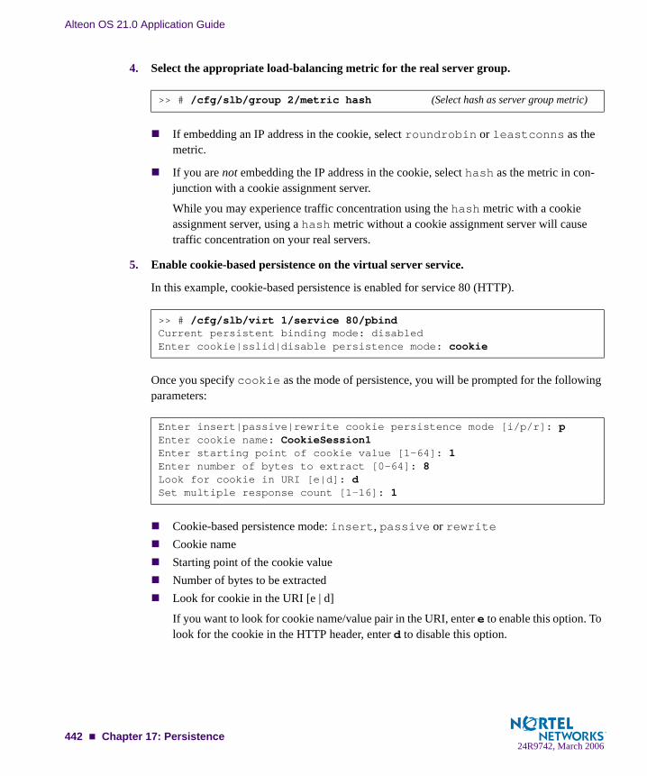
Alteon OS 21.0 Application Guide
4. Select the appropriate load-balancing metric for the real server group.
If embedding an IP address in the cookie, select roundrobin or leastconns as the metric.
If you are not embedding the IP address in the cookie, select hash as the metric in con-junction with a cookie assignment server.
While you may experience traffic concentration using the hash metric with a cookie assignment server, using a hash metric without a cookie assignment server will cause traffic concentration on your real servers.
5. Enable cookie-based persistence on the virtual server service.
In this example, cookie-based persistence is enabled for service 80 (HTTP).
Once you specify cookie as the mode of persistence, you will be prompted for the following parameters:
Cookie-based persistence mode: insert, passive or rewriteCookie nameStarting point of the cookie valueNumber of bytes to be extractedLook for cookie in the URI [e | d]
If you want to look for cookie name/value pair in the URI, enter e to enable this option. To look for the cookie in the HTTP header, enter d to disable this option.
>> # /cfg/slb/group 2/metric hash (Select hash as server group metric)
>> # /cfg/slb/virt 1/service 80/pbindCurrent persistent binding mode: disabledEnter cookie|sslid|disable persistence mode: cookie
Enter insert|passive|rewrite cookie persistence mode [i/p/r]: pEnter cookie name: CookieSession1Enter starting point of cookie value [1-64]: 1Enter number of bytes to extract [0-64]: 8Look for cookie in URI [e|d]: dSet multiple response count [1-16]: 1
442 Chapter 17: Persistence24R9742, March 2006

Alteon OS 21.0 Application Guide
Set multiple response count
This parameter is set for passive mode only. Typically, the switch searches the first HTTP response packet from the server and, if a persistence cookie is found, sets up a persistent connection between the server and the client. While this approach works for most servers, some customers with complex server configurations might send the persistence cookie a few responses later. In order to achieve cookie-based persistence in such cases, Alteon OS allows the network administrator to configure the switch to look through multiple HTTP responses from the server. The switch looks for the persistence cookie in the specified number of responses (each of them can be multi-frame) from the server.
Setting Expiration Timer for Insert CookieIf you configure for insert cookie persistence mode, then you will be prompted for cookie expi-ration timer. The expiration timer specifies a date string that defines the valid life time of that cookie. The expiration timer for insert cookie can be of the following types:
Absolute timer
The syntax for the absolute timer is MM/dd/yy[@hh:mm]. The date and time is based on RFC 822, RFC 850, RFC 1036, and RFC 1123, with the variations that the only legal time zone is GMT. Once the expiration date is met, the cookie is not stored or given out. For example,
Relative timer
This timer defines the elapsed time from when the cookie was created. The syntax for the rela-tive timer is days[:hours[:minutes]]. For example,
NOTE – If the cookie expiration timer is not specified, the cookie will expire when the user's session ends.
Enter cookie expiration: 12/31/01@11:59Current persistent binding for http: disabledNew persistent binding for http: cookieNew cookie persistence mode: insertInserted cookie expires on Mon 12/31/01 at 11:59
Enter cookie expiration: 32:25:61Current persistent binding for http: disabledNew persistent binding for http: cookieNew cookie persistence mode: insertInserted cookie expires after 33 days 2 hours 1 minutes
Chapter 17: Persistence 44324R9742, March 2006

Alteon OS 21.0 Application Guide
Example 1: Setting the Cookie LocationIn this example, the client request has two different cookies labeled “UID.” One exists in the HTTP header and the other appears in the URI:
GET /product/switch/UID=12345678;ck=1234...Host: www.nortelnetworks.comCookie: UID=87654321
Look for the cookie in the HTTP header
The last parameter in this command answers the “Look for cookie in URI?” prompt. If you set this parameter to disable, the switch will use UID=87654321 as the cookie.
Look for the cookie in the URI
The last “Look for cookie in URI?” parameter is set to enable. Therefore the switch will use UID=12345678 as the cookie.
>> # /cfg/slb/virt 1/service 80/pbind cookie passive UID 1 8 dis
>> # /cfg/slb/virt 1/service 80/pbind cookie passive UID 1 8 ena
444 Chapter 17: Persistence24R9742, March 2006

Alteon OS 21.0 Application Guide
Example 2: Parsing the CookieThis example shows three configurations where the switch uses the hashing key or wild cards to determine which part of the cookie value should be used for determining the real server. For example, the value of the cookie is defined as follows:
Cookie: sid=0123456789abcdef; name1=value1;...
Select the entire value of the sid cookie as a hashing key for selecting the real server:
This command directs the switch to use the sid cookie, starting with the first byte in the value and using the full 16 bytes.
Select a specific portion of the sid cookie as a hashing key for selecting the real server:
This command directs the switch to use the sid cookie, starting with the eight byte in the value and using only four bytes. This uses 789a as a hashing key.
Using wildcards for selecting cookie names:
With this configuration, the switch will look for a cookie name that starts with ASPSES-SIONID. ASPSESSIONID123, ASPSESSIONID456, and ASPSESSIONID789 will all be seen by the switch as the same cookie name. If more than one cookie matches, only the first one will be used.
Example 3: Using Passive Cookie ModeIf you are using passive cookie mode, the switch examines the server’s Set-Cookie: value and directs all subsequent connections to the server that assigned the cookie.
For example, if Server 1 sets the cookie as “Set-Cookie: sid=12345678,” then all traf-fic from a particular client with cookie sid=12345678 will be directed to Server 1.
The following command is used on the switch:
>> # /cfg/slb/virt 1/service 80/pbind cookie passive sid 1 16 dis
>> # /cfg/slb/virt 1/service 80/pbind cookie passive sid 8 4 dis
>> # /cfg/slb/virt 1/service 80/pbind cookie passiveASPSESSIONID* 1 16 dis
>> # /cfg/slb/virt 1/service 80/pbind cookie passive sid 1 8 dis
Chapter 17: Persistence 44524R9742, March 2006

Alteon OS 21.0 Application Guide
Example 4: Using Rewrite Cookie ModeRewrite server cookie with the encrypted real server IP address:
In cookie rewrite mode, if the cookie length parameter is configured to be eight bytes, the switch will rewrite the placeholder cookie value with the encrypted real server IP address.
If the server is configured to include a placeholder cookie, such as follows:
Set-Cookie: sid=alteonpersistence;
then the switch will rewrite the first eight bytes of the cookie to include the server’s encrypted IP address:
Set-Cookie: sid=cdb20f04rsistence;
All subsequent traffic from a specific client with this cookie will be directed to the same real server.
Rewrite server cookie with the encrypted real server IP address and virtual server IP address:
If the cookie length is configured to be 16 bytes, the switch will rewrite the cookie value with the encrypted real server IP address and virtual server IP address.
If the server is configured to include a placeholder cookie, as follows:
Set-Cookie: sid=alteonwebcookies;
then the switch will rewrite the first 16 bytes of the cookie to include the encrypted real server IP address and virtual server IP address:
Set-Cookie: sid=cdb20f04cdb20f0a;
All subsequent traffic from a specific client to the particular virtual server IP address with this cookie will be directed to the same real server.
>> # /cfg/slb/virt 1/service 80/pbind cookie rewrite sid 1 8 dis
>> # /cfg/slb/virt 1/service 80/pbind cookie rewrite sid 1 16 dis
446 Chapter 17: Persistence24R9742, March 2006
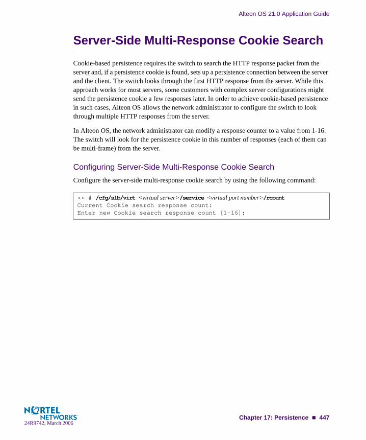
Alteon OS 21.0 Application Guide
Server-Side Multi-Response Cookie SearchCookie-based persistence requires the switch to search the HTTP response packet from the server and, if a persistence cookie is found, sets up a persistence connection between the server and the client. The switch looks through the first HTTP response from the server. While this approach works for most servers, some customers with complex server configurations might send the persistence cookie a few responses later. In order to achieve cookie-based persistence in such cases, Alteon OS allows the network administrator to configure the switch to look through multiple HTTP responses from the server.
In Alteon OS, the network administrator can modify a response counter to a value from 1-16. The switch will look for the persistence cookie in this number of responses (each of them can be multi-frame) from the server.
Configuring Server-Side Multi-Response Cookie SearchConfigure the server-side multi-response cookie search by using the following command:
>> # /cfg/slb/virt <virtual server>/service <virtual port number>/rcountCurrent Cookie search response count:Enter new Cookie search response count [1-16]:
Chapter 17: Persistence 44724R9742, March 2006
Alteon OS 21.0 Application Guide
SSL Session ID-Based PersistenceSSL is a set of protocols built on top of TCP/IP that allows an application server and client to communicate over an encrypted HTTP session, providing authentication, non-repudiation, and security. The SSL protocol handshake is performed using clear (unencrypted) text. The content data is then encrypted (using an algorithm exchanged during the handshake) prior to being transmitted.
Using the SSL session ID, the switch forwards the client request to the same real server to which it was bound during the last session. Because SSL protocol allows many TCP connec-tions to use the same session ID from the same client to a server, key exchange needs to be done only when the session ID expires. This reduces server overhead and provides a mecha-nism, even when the client IP address changes, to send all sessions to the same real server.
NOTE – The destination port number to monitor for SSL traffic is user-configurable.
How SSL Session ID-Based Persistence WorksAll SSL sessions that present the same session ID (32 random bytes chosen by the SSL server) will be directed to the same real server.
NOTE – The SSL session ID can only be read by the switch after the TCP three-way hand-shake. In order to make a forwarding decision, the switch must terminate the TCP connection to examine the request.
New sessions are sent to the real server based on the metric selected (hash,roundrobin, leastconns, minmisses, response, and bandwidth).
If no session ID is presented by the client, the switch picks a real server based on the met-ric for the real server group and waits until a connection is established with the real server and a session ID is received.
The session ID is stored in a session hash table. Subsequent connections with the same session ID are sent to the same real server. This binding is preserved even if the server changes the session ID mid-stream. A change of session ID in the SSL protocol will cause a full three-way handshake to occur.
Session IDs are kept on the switch until an idle time equal to the configured server time-out (a default of 10 minutes) for the selected real server has expired.
448 Chapter 17: Persistence24R9742, March 2006
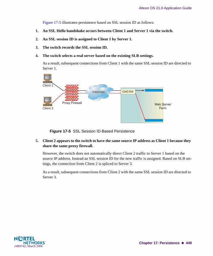
Alteon OS 21.0 Application Guide
Figure 17-5 illustrates persistence based on SSL session ID as follows:
1. An SSL Hello handshake occurs between Client 1 and Server 1 via the switch.
2. An SSL session ID is assigned to Client 1 by Server 1.
3. The switch records the SSL session ID.
4. The switch selects a real server based on the existing SLB settings.
As a result, subsequent connections from Client 1 with the same SSL session ID are directed to Server 1.
Figure 17-5 SSL Session ID-Based Persistence
5. Client 2 appears to the switch to have the same source IP address as Client 1 because they share the same proxy firewall.
However, the switch does not automatically direct Client 2 traffic to Server 1 based on the source IP address. Instead an SSL session ID for the new traffic is assigned. Based on SLB set-tings, the connection from Client 2 is spliced to Server 3.
As a result, subsequent connections from Client 2 with the same SSL session ID are directed to Server 3.
1
5
2
3
4
InternetInternet
Client 1
Client 2
GbESM
Chapter 17: Persistence 44924R9742, March 2006
Alteon OS 21.0 Application Guide
Configuring SSL Session ID-Based PersistenceTo configure session ID-based persistence for a real server, perform the following steps:
1. Configure real servers and services for basic SLB, as indicated below:
Define each real server and assign an IP address to each real server in the server pool.
Define a real server group and set up health checks for the group.
Define a virtual server on the virtual port for HTTPS (for example, port 443) and assign a real server group to service it.
Enable SLB on the switch.
Enable client processing on the port connected to the client.
For information on how to configure your network for SLB, see “Server Load Balancing” on page 171
2. If a proxy IP address is not configured on the client port, enable DAM for real servers.
3. Select session ID-based persistence as the persistent binding option for the virtual port.
4. Enable client processing on the client port.
Windows Terminal Server Load Balancing and PersistenceWindows Terminal Services refer to a set of technologies that allow Windows users to run Windows-based applications remotely on a computer running the Windows Terminal Server application. Alteon OS 21.0 includes load balancing and persistence options aimed specifi-cally at Windows Terminal Services.
>> # /cfg/slb/adv/direct ena
>> # /cfg/slb/virt <virtual server number>/service <virtual port> pbind sslid
>> # /cfg/slb/port <port number>/client ena
450 Chapter 17: Persistence24R9742, March 2006

Alteon OS 21.0 Application Guide
In a load-balanced environment, a group of terminal servers have incoming session connec-tions distributed in a balanced manner across the servers in the group. The Windows session director is used to keeping a list of sessions indexed by user name. This allows a user to recon-nect to a disconnected user session.
Configuring Windows Terminal Server Load Balancing and PersistenceTo configure this feature, follow this procedure:
1. Access the Windows Terminal Server menu.
2. Enable the Windows Terminal Server feature.
3. (Optional) Enable the WTS userhash.
If the dedicated session director does not exist to relate users to disconnected sessions, it is advised that the userhash functionality be enabled to perform this task.
>> Main# /cfg/slb/virt <virtual server number>/service 3389/wts
>> WTS Load Balancing# ena
>> WTS Load Balancing# userhash enable
Chapter 17: Persistence 45124R9742, March 2006

Alteon OS 21.0 Application Guide
452 Chapter 17: Persistence24R9742, March 2006

APPENDIX ATroubleshooting
This section discusses some tools to help you troubleshoot common problems on the GbE Switch Module:
“Monitoring Ports” on page 454
“Filtering the Session Dump” on page 457
24R9742, March 2006453

Alteon OS 21.0 Application Guide
Monitoring PortsThe port mirroring feature in the Alteon OS allows you to attach a sniffer to a monitoring port that is configured to receive a copy of all packets that are forwarded from the mirrored port. Alteon OS enables you to mirror port traffic for all layers (Layer 2 - 7). Port mirroring can be used as a troubleshooting tool or to enhance the security of your network. For example, an IDS server can be connected to the monitor port to detect intruders attacking the network.
As shown in Figure A-1, port 3 is monitoring ingress traffic (traffic entering the switch) on port 1 and egress traffic (traffic leaving the switch) on port 2. You can attach a device to port 3 to monitor the traffic on ports 1 and 2.
Figure A-1 Monitoring Ports
Figure A-1 shows two mirrored ports monitored by a single port. Similarly, you can have a sin-gle or groups of
one mirrored port to one monitored portmore than two mirrored ports to one monitored port
Alteon OS does not support a single port being monitored by multiple ports.
Ingress and egress traffic is duplicated and sent to the monitor port after processing.
NOTE – The GbESM cannot mirror LACPDU packets.
NOTE – Traffic on VLAN 4095 is not mirrored to the external ports.
OK
1
2
3
4
TX/RX
TX/RX
TX/RX
TX/RX
LINK
LINK
LINK
LINK
OK
1
2
3
4
TX/RX
TX/RX
TX/RX
TX/RX
LINK
LINK
LINK
LINK
Monitoring port
Mirrored ports
Ingress
Egress
454 Appendix A: Troubleshooting24R9742, March 2006
Alteon OS 21.0 Application Guide
Port Mirroring behaviorThis section describes the composition of monitored packets in the GbE Switch Module, based on the configuration of the ports.
Same VLAN as Mirrored Port
Both ports tagged: Tagged packet with VID of the VLAN to which the ports belong
Mirrored port tagged, Monitoring port untagged: Untagged packet
Mirrored port untagged, Monitoring port tagged: Tagged packet with VID of the VLAN to which both ports belong
Both ports untagged: Untagged packet
Different VLAN from Mirrored Port
Both ports tagged: Tagged packet with VID of mirrored port
Mirrored port tagged, Monitoring port untagged: Tagged packet with VID of mirrored port
Mirrored port untagged, Monitoring port tagged: Tagged packet with VID of mirrored port
Both ports untagged: Tagged packet with VID of mirrored port
NOTE – When the monitoring port belongs to a different VLAN, all mirrored packets have an 802.1Q tag field with the VID of the VLAN to which the mirrored port belongs. The VID included in the tag field depends on which port is monitored.
For example, assume a packet traverses from port EXT1 (VLAN 1) to EXT2 (VLAN 2), and is monitored on port EXT3. When you monitor EXT1, the packet’s tag includes the VID of VLAN1. When you monitor EXT2, the packet’s tag includes the VID of VLAN 2.
Configuring Port MirroringTo configure port mirroring for the example shown in Figure A-1,
1. Specify the monitoring port.
>> # /cfg/pmirr/monport EXT3 (Select port EXT3 for monitoring)
Appendix A: Troubleshooting 45524R9742, March 2006

Alteon OS 21.0 Application Guide
2. Select the ports that you want to mirror.
3. Enable port mirroring.
4. Apply and save the configuration.
5. View the current configuration.
>> Port EXT3 # add EXT1 (Select port EXT1 to mirror)>> Enter port mirror direction [in, out, or both]: in
(Monitor ingress traffic on port EXT1)>> Port EXT3 # add EXT2 (Select port EXT2 to mirror)>> Enter port mirror direction [in, out, or both]: out
(Monitor egress traffic on port EXT2)
>> # /cfg/pmirr/mirr ena (Enable port mirroring)
>> PortMirroring# apply (Apply the configuration)>> PortMirroring# save (Save the configuration)
>> PortMirroring# cur (Display the current settings)Port mirroring is enabledMonitoring Ports Mirrored PortsINT1 noneINT2 noneINT3 noneINT4 noneINT5 none---------------EXT1 noneEXT2 noneEXT3 (EXT1, in) (EXT2, out)EXT4 none
456 Appendix A: Troubleshooting24R9742, March 2006

Alteon OS 21.0 Application Guide
Filtering the Session DumpTypically, session dumps are long and unwieldy. Alteon OS however, provides a tool to filter session dumps based on any of the following attributes:
Client IP addressSource portDestination IP addressDestination portProxy IP addressProxy portMatching filterMatching flagIngress portReal IP addressSP
Only one attribute can be used at a time to filter the session dump. For example, to filter a ses-sion dump based on client IP address 10.10.10.1, use the following command:
Because VMA is enabled, the command displayed all sessions for client IP address 10.10.10.1 on SP 1. The sessions hash on source IP address and destination IP address.
>> # /info/slb/sess/cip 10.10.10.1Printing Sessions for SP 11,01: 10.10.10.1 137, 205.178.13.100 137 ALLOW age 2 f:100 E1,01: 10.10.10.1 2592, 172.21.31.100 http -> 14291 10.20.1.2 http age 01,01: 10.10.10.1 2593, 172.21.31.100 http -> 14292 10.20.1.3 http age 01,01: 10.10.10.1 2594, 172.21.31.100 http -> 14307 10.20.1.2 http age 01,01: 10.10.10.1 2595, 172.21.31.100 http -> 14308 10.20.1.3 http age 01,01: 10.10.10.1 2596, 172.21.31.100 http -> 14309 10.20.1.4 http age 01,01: 10.10.10.1 2597, 172.21.31.100 http -> 14310 10.20.1.3 http age 01,01: 10.10.10.1 2598, 172.21.31.100 http -> 14311 10.20.1.4 http age 01,01: 10.10.10.1 2599, 172.21.31.100 http -> 14339 10.20.1.3 http age 01,01: 10.10.10.1 2600, 172.21.31.100 http -> 14340 10.20.1.4 http age 01,01: 10.10.10.1 2601, 172.21.31.100 http -> 14367 10.20.1.3 http age 01,01: 10.10.10.1 2602, 172.21.31.100 http -> 14384 10.20.1.2 http age 101,01: 10.10.10.1 2603, 172.21.31.100 http -> 14385 10.20.1.3 http age 101,01: 10.10.10.1 2604, 172.21.31.100 http -> 14414 10.20.1.2 http age 10
>> Session Table Information#
Appendix A: Troubleshooting 45724R9742, March 2006

Alteon OS 21.0 Application Guide
458 Appendix A: Troubleshooting24R9742, March 2006
APPENDIX BRadius Server Configuration Notes
Use the following information to modify your RADIUS configuration files for the Nortel Net-works BaySecure Access Control RADIUS server, to provide authentication for users of the GbE Switch Module.
1. Create a dictionary file called alteon.dct, with the following content:
#################################################################### alteon.dct - RADLINX Alteon dictionary# # (See README.DCT for more details on the format of this file)##################################################################### Use the Radius specification attributes in lieu of the # RADLINX Alteon ones#@radius.dct
## Define additional RADLINX Alteon parameters# (add RADLINX Alteon specific attributes below)
ATTRIBUTE Radlinx-Vendor-Specific 26 [vid=648 data=string] R
################################################################### alteon.dct - RADLINX Alteon dictionary####################################################################Define Alteon GbESM Layer 2 & Layer 3 dictionary#@radius.dct
@alteon.dctVALUE Service-Type user 255VALUE Service-Type slboper 254VALUE Service-Type l4oper 253VALUE Service-Type oper 252VALUE Service-Type slbadmin 251VALUE Service-Type l4admin 250
##################################################################
24R9742, March 2006459

Alteon OS 21.0 Application Guide
2. Open the dictiona.dcm file, and add the following line (as in the example):
@alteon.dct
3. Open the vendor file (vendor.ini), and add the following data to the Vendor-Product identification list:
vendor-product = Alteon Blade-server moduledictionary = alteonignore-ports = nohelp-id = 0
#################################################################### dictiona.dcm#################################################################### Generic Radius
@radius.dct
## Specific Implementations (vendor specific)#@[email protected]@[email protected] ...################################################################### dictiona.dcm##################################################################
460 Appendix B: Radius Server Configuration Notes24R9742, March 2006
Glossary
DIP (Destination IP Address)
The destination IP address of a frame.
Dport (Destination Port)
The destination port (application socket: for example, http-80/https-443/DNS-53)
NAT (Network Address Translation)
Any time an IP address is changed from one source IP or destination IP address to another address, network address translation can be said to have taken place. In general, half NAT is when the destination IP or source IP address is changed from one address to another. Full NAT is when both addresses are changed from one address to another. No NAT is when neither source nor destination IP addresses are translated. Virtual server-based load balancing uses half NAT by design, because it translates the destination IP address from the Virtual Server IP address, to that of one of the real servers.
Preemption In VRRP, preemption will cause a Virtual Router that has a lower priority to go into backup should a peer Virtual Router start advertising with a higher priority.
Priority In VRRP, the value given to a Virtual Router to determine its ranking with its peer(s). Min-imum value is 1 and maximum value is 254. Default is 100. A higher number will win out for master designation.
Proto (Protocol) The protocol of a frame. Can be any value represented by a 8-bit value in the IP header adherent to the IP specification (for example, TCP, UDP, OSPF, ICMP, and so on.)
Real Server Group A group of real servers that are associated with a Virtual Server IP address, or a filter.
Redirection or Filter-Based Load Balancing
A type of load balancing that operates differently from virtual server-based load balancing. With this type of load balancing, requests are transparently intercepted and “redirected” to a server group. “Transparently” means that requests are not specifically destined for a Vir-tual Server IP address that the switch owns. Instead, a filter is configured in the switch. This filter intercepts traffic based on certain IP header criteria and load balances it.Filters can be configured to filter on the SIP/Range (via netmask), DIP/Range (via net-mask), Protocol, SPort/Range or DPort/Range. The action on a filter can be Allow, Deny, Redirect to a Server Group, or NAT (translation of either the source IP or destination IP address). In redirection-based load balancing, the destination IP address is not translated to that of one of the real servers. Therefore, redirection-based load balancing is designed to load balance devices that normally operate transparently in your network—such as a fire-wall, spam filter, or transparent Web cache.
RIP (Real Server) Real Server IP Address. An IP addresses that the switch load balances to when requests are made to a Virtual Server IP address (VIP).
24R9742, March 2006461

Alteon OS 21.0 Application Guide
SIP (Source IP Address)
The source IP address of a frame.
SPort (Source Port) The source port (application socket: for example, HTTP-80/HTTPS-443/DNS-53).
Tracking In VRRP, a method to increase the priority of a virtual router and thus master designation (with preemption enabled). Tracking can be very valuable in an active/active configura-tion.You can track the following:
Vrs: Virtual Routers in Master Mode (increments priority by 2 for each)Ifs: Active IP interfaces on the Web switch (increments priority by 2 for each)Ports: Active ports on the same VLAN (increments priority by 2 for each)l4pts: Active Layer 4 Ports, client or server designation (increments priority by 2 for eachreals: healthy real servers (increments by 2 for each healthy real server)hsrp: HSRP announcements heard on a client designated port (increments by 10 for each)
VIP (Virtual Server IP Address)
An IP address that the switch owns and uses to load balance particular service requests (like HTTP) to other servers.
VIR (Virtual Interface Router)
A VRRP address that is an IP interface address shared between two or more virtual rout-ers.
Virtual Router A shared address between two devices utilizing VRRP, as defined in RFC 2338. One vir-tual router is associated with an IP interface. This is one of the IP interfaces that the switch is assigned. All IP interfaces on the GbE Switch Modules must be in a VLAN. If there is more than one VLAN defined on the Web switch, then the VRRP broadcasts will only be sent out on the VLAN of which the associated IP interface is a member.
Virtual Server Load Balancing
Classic load balancing. Requests destined for a Virtual Server IP address (VIP), which is owned by the switch, are load balanced to a real server contained in the group associated with the VIP. Network address translation is done back and forth, by the switch, as requests come and go.Frames come to the switch destined for the VIP. The switch then replaces the VIP and with one of the real server IP addresses (RIP's), updates the relevant checksums, and forwards the frame to the server for which it is now destined. This process of replacing the destina-tion IP (VIP) with one of the real server addresses is called half NAT. If the frames were not half NAT'ed to the address of one of the RIPs, a server would receive the frame that was destined for it's MAC address, forcing the packet up to Layer 3. The server would then drop the frame, since the packet would contain the destination IP of the VIP and not that of the server (RIP).
VRID (Virtual Router Identifier)
In VRRP, a value between 1 and 255 that is used by each virtual router to create its MAC address and identify its peer for which it is sharing this VRRP address. The VRRP MAC address as defined in the RFC is 00-00-5E-00-01-{VRID}. If you have a VRRP address that two switches are sharing, then the VRID number needs to be identical on both switches so each virtual router on each switch knows whom to share with.
462 : Glossary24R9742, March 2006

Alteon OS 21.0 Application Guide
VRRP (Virtual Router Redundancy Protocol)
A protocol that acts very similarly to Cisco's proprietary HSRP address sharing protocol. The reason for both of these protocols is so devices have a next hop or default gateway that is always available. Two or more devices sharing an IP interface are either advertising or listening for advertisements. These advertisements are sent via a broadcast message to an address such as 224.0.0.18.With VRRP, one switch is considered the master and the other the backup. The master is always advertising via the broadcasts. The backup switch is always listening for the broad-casts. Should the master stop advertising, the backup will take over ownership of the VRRP IP and MAC addresses as defined by the specification. The switch announces this change in ownership to the devices around it by way of a Gratuitous ARP, and advertise-ments. If the backup switch didn't do the Gratuitous ARP the Layer 2 devices attached to the switch would not know that the MAC address had moved in the network. For a more detailed description, refer to RFC 2338.
VSR (Virtual Server Router)
A VRRP address that is a shared Virtual Server IP address. VSR is Alteon OS proprietary extension to the VRRP specification. The switches must be able to share Virtual Server IP addresses, as well as IP interfaces. If they didn’t, the two switches would fight for owner-ship of the Virtual Server IP address, and the ARP tables in the devices around them would have two ARP entries with the same IP address but different MAC addresses.
: Glossary 46324R9742, March 2006

Alteon OS 21.0 Application Guide
464 : Glossary24R9742, March 2006

Index
Symbols[ ]....................................................................... 21
Numerics80 (port) ................................................... 219, 225802.1Q VLAN tagging......................................... 62
Aaccessing the switch
defining source IP addresses........................... 37RADIUS authentication................................. 38security........................................................ 36using the Browser-based Interface................... 31
active cookie mode ............................................ 440active-active redundancy.................................... 339
Server Load Balancing ................................ 353synchronization .......................................... 347
active-standby redundancy ................................. 338configuration.............................................. 350
administrator account........................................... 41aggregating routes ............................................. 127
example..................................................... 133allow (filtering) ......................................... 174, 250application health checking ................................ 309application ports................................................ 182application redirection ............................... 252, 287
client IP address authentication..................... 297example with NAT ..................................... 292games and real-time applications .................. 297non cacheable sites...................................... 297non-HTTP redirects for GSLB...................... 242proxies ................................... 289, 292 to 295rport .................................................. 292, 296See cache redirectiontopologies .................................................. 290Web-cache redirection example ......... 288 to 297
authenticating, in OSPF...................................... 147authoritative name servers .................................. 211autonomous systems (AS) .................................. 140
Bbackup servers................................................... 189bandwidth metric ............................................... 187BBI
See Browser-Based Interface ........................ 141Border Gateway Protocol (BGP) ......................... 121
attributes .................................................... 128failover configuration .................................. 130route aggregation ........................................ 127route maps.................................................. 123selecting route paths .................................... 129use with GSLB ........................................... 246
Bridge Protocol Data Unit (BPDU) ....................... 87broadcast domains ....................................... 59, 105Browser-Based Interface ............ 141, 219, 225, 304
Ccache redirection
browser-based............................................. 416delayed binding .......................................... 294example ..................................................... 290HTTP header-based..................................... 415layer 7 traffic .............................................. 405See application redirectionservers ....................................288 to 290, 291URL hashing .............................................. 417URL-based................................................. 406
CGI-bin scripts .......................................... 176, 188Cisco EtherChannel ....................................... 78, 81client traffic processing ...................................... 176command conventions.......................................... 21Command Line Interface .................................... 141
24R9742, March 2006465

Alteon OS 21.0 Application Guide
configuration rulesport mirroring................................................78spanning tree.................................................78Trunking ......................................................78VLANs ........................................................78
configuringBGP failover...............................................130cache redirection .........................................290cookie-based persistence ..............................441default filter ................................................254delayed binding ...........................................202dynamic NAT .............................................275filter-based security......................................267IP routing ...................................................103multiple services..........................................184multi-response cookie search.........................447OSPF .........................................................151port trunking .................................................80proxy IP addresses .......................................192server load balancing ...................................177spanning tree groups ......................................93static NAT..................................................274TCP rate limiting filters ................................261tunable hash for filter redirection ...................265VLAN-based filters .....................................255
connection time-out............................................188content intelligent
cache redirection .........................................405server load balancing ...................................387
cookieactive .........................................................440different types .............................................437expiration timer ...........................................443header ........................................................435insert mode .................................................437names ........................................................436passive mode ..............................................439permanent...................................................435temporary ...................................................435values.........................................................436
cookie-based persistence.....................................434
Ddefault gateway ................................................. 102
configuration example ... 72, 104, 220, 226, 232VLAN-based................................................ 69
default password.................................................. 41default route
OSPF ........................................................ 145delayed binding .............................. 200 to 202, 385
cache redirection......................................... 294deny (filtering) .......................................... 174, 250detecting SYN attacks........................................ 202dip (destination IP address for filtering) ............... 259disabling real servers ......................................... 183Distributed Site State Protocol (DSSP) ................ 210dmask
destination mask for filtering ........................ 259Domain Name System (DNS)
filtering.............................................. 266, 269Global SLB (diagram) ................................. 211load balancing, layer 7................................. 402round robin ................................................ 172
dport (filtering option) ............................... 268, 293DSSP. See Distributed Site State Protocol.dynamic NAT ................................................... 275
EEnd user access control
configuring .................................................. 55EtherChannel ...................................................... 76
as used with port trunking ........................ 78, 81expiration timer, insert cookie............................. 443external routing ......................................... 122, 140
Ffailed server protection, SLB .............................. 172failover
overview.................................................... 337fault tolerance
port trunking ................................................ 77Server Load Balancing ................................ 176
filter redirectiontunable hash ............................................... 265
466 Index24R9742, March 2006

Alteon OS 21.0 Application Guide
filteringconfiguration example ................................. 267default filter ....................................... 253, 267IP address ranges ........................................ 259layer 7 deny ............................................... 429NAT configuration example.............. 272 to 274numbering ................................................. 257order of precedence............................. 252, 253proto (option) ..................................... 268, 293security example......................................... 266session dumps ............................................ 457TCP rate limiting ........................................ 261
filtering-based VLANs....................................... 255firewalls ........................................................... 267fragmenting jumbo frames.......................... 100, 103frame tagging. See VLANs tagging.FTP
applications................................................ 183proxy IP .................................................... 242
Ggateway. See default gateway.Global SLB
configuration tutorial........218 to 230, ?? to 234Distributed Site State Protocol ...................... 210DNS resolution (diagram) ............................ 211domain name configuration.......................... 224health check interval ................................... 223hostname configuration ............................... 224HTTP redirect ............................................ 212port states .................................................. 222real server groups........................................ 221real servers................................................. 221remote site configuration ............................. 223tests .......................................................... 247using proxy IP ............................................ 242
group SLB, metrics............................................ 185
Hhash metric ....................................................... 186hashing
redirection filters ........................................ 265hashing on any HTTP header.............................. 401
health checks............................................. 292, 315configuration using scripts............................ 306format........................................................ 305Global SLB interval..................................... 223hostname for HTTP content...............309 to 310HTTPS/SSL ............................................... 318IMAP server............................................... 315RADIUS server .......................................... 317real server parameters .................................. 309real servers ................................................. 184script-based .....................................304 to 307verifying scripts .......................................... 307wireless session protocol ...................318 to 320WSP.......................................................... 319WTLS ....................................................... 320
high-availability ................................................ 325Host routes
OSPF......................................................... 150hostname, for HTTP health checks .............. 224, 309hot-standby redundancy...................................... 340HP-OpenView..................................................... 33HTTP
application health checks.............................. 309redirects (Global SLB option) ....................... 212
HTTP headerhashing ...................................................... 401
HTTP URL request ............................................ 428HTTPS/SSL health checks.................................. 318
IICMP ............................................................... 251IGMP ............................................................... 251IGMP Snooping................................................. 113IMAP server health checks ................................. 315imask................................................................ 183incoming route maps.......................................... 124insert cookie mode............................................. 437
expiration timer........................................... 443internal routing .......................................... 122, 140Internet Service Provider (ISP), SLB example ...... 175inter-switch port states, for hot-standby redundancy....
341
Index 46724R9742, March 2006

Alteon OS 21.0 Application Guide
IP addressconservation................................................272filter ranges.................................................259local route cache ranges................................107private........................................................272proxies ........................... 190, 289, 292 to 295real server groups ................179, 221, 356, 412real servers .................................174, 177, 221routing example.....................................71, 103SLB real servers ..........................................179virtual servers..............................174, 179, 222
IP interfacesconfiguration example..........178, 220, 226, 232example configuration....................71, 103, 106
IP proxiesfor application redirection.............................295for Global Server Load Balancing..................242for Server Load Balancing ............................190See also proxies, proxy IP address (PIP).
IP routing ..........................................................176cross-subnet example ...................................100default gateway configuration .................72, 104IP interface configuration ...............71, 103, 106IP subnets ...................................................101network diagram..........................................101subnet configuration example........................103switch-based topology..................................102
IP subnets..........................................................102routing ...............................................101, 102VLANs ........................................................59
ISL Trunking .......................................................76
Jjumbo frames
fragmenting to normal size....................100, 103routing ...............................................100, 103
LLACP .................................................................82Layer 4
administrator account .....................................41cache redirection .........................................290server load balancing ...................................177
Layer 7cache redirection......................................... 405deny filter .................................................. 429precedence lookup ...................................... 425regular expression matching ......................... 423server load balancing................................... 387string matching........................................... 421
least connections (SLB Real Server metric).......... 186leastconn metric ................................................ 186Link Aggregation Control Protocol ....................... 82lmask (local route cache parameter) .................... 107lnet (local route cache parameter)........................ 107load balancing
DNS.......................................................... 402layer 7 traffic.............................................. 387SIP traffic .................................................. 203
local route cache address range ........................... 107local route cache parameters
lmask ........................................................ 107lnet............................................................ 107
logfiltering option............................................ 250
log (filtering option) .......................................... 266logical segment. See IP subnets.LSAs................................................................ 139
Mmanagement module ............................................ 26Management Processor (MP)
use in switch security..................................... 37manual style conventions ..................................... 21mapping ports ................................................... 296mapping virtual ports to real ports ....................... 193matching TCP flags ........................................... 279maxcons limit............................................ 188, 189maximum connections ............................... 188, 189metrics
real server groups........................................ 185MIBs, SNMP ...................................................... 35minimum misses (SLB real server metric)............ 185minmiss metric.................................................. 185mirroring ports .................................................. 454monitoring ports ................................................ 454monitoring real servers....................................... 199multi-homing .................................................... 246multi-links between switches
using port trunking........................................ 75multiple services, configuring ............................. 184
468 Index24R9742, March 2006

Alteon OS 21.0 Application Guide
multiple spanning tree groups ............................... 91
Nname servers, Global SLB configuration example. 211Network Address Translation (NAT)................... 292
configuration example ...................... 272 to 274filter action ................................................ 252filter example ............................................. 276proxy ........................................................ 276static example............................................. 272
network management........................................... 33network performance
statistics, with use of proxy addresses ............ 190NFS server........................................................ 175non cacheable sites in application redirection ....... 297none (port processing mode) example.................. 180non-HTTP redirects for GSLB............................ 242
OOSPF
area types................................................... 136authentication............................................. 147configuration examples..................... 152 to 167default route............................................... 145external routes ............................................ 151filtering criteria........................................... 251host routes ................................................. 150link state database ....................................... 139neighbors................................................... 139overview.................................................... 136redistributing routes ............................ 123, 127route maps ......................................... 123, 125route summarization.................................... 144router ID.................................................... 147virtual link ................................................. 146
outgoing route maps .......................................... 124overflow servers................................................ 189
Ppassword
administrator account .................................... 41default ......................................................... 41L4 administrator account ............................... 41user account ................................................. 41
persistencecookie-based .............................................. 434multi-reponse cookie search ......................... 447SSL session ID-based .......................448 to 450
persistentbindings ..................................................... 176
PIP. See proxies, proxy IP address.POP3................................................................ 242port 80 ...................................................... 219, 225port mapping ..................................................... 296port mirroring.................................................... 454
configuration rules ........................................ 78port processing mode
none .......................................................... 180server ................................................ 176, 180
port states.......................................................... 222Port Trunking ...................................................... 77port trunking ....................................................... 77
configuration example ................................... 79description ................................................... 81EtherChannel................................................ 76fault tolerance............................................... 77
portsfor services................................................. 182monitoring ................................................. 454physical. See switch ports.SLB configuration example .......................... 180
private IP address .............................................. 272private network.................................................. 272protocol types.................................................... 251proxies..................................... 190, 289 to ??, 295
configuration example ................................. 276NAT.......................................................... 275
proxy IP address (PIP)........................ 190, 198, 295proxy servers..................................................... 289PVID (port VLAN ID) ......................................... 61
RRADIUS
authentication ............................................... 38health checks .............................................. 317port 1812 and 1645...................................... 182port 1813 ................................................... 182server parameters ........................................ 317SSH/SCP ..................................................... 53
real server groupsconfiguration example ................. 221, 356, 412
Index 46924R9742, March 2006

Alteon OS 21.0 Application Guide
real serversbackup/overflow servers...............................189configuration example..................................221connection timeouts .....................................188disable/enable .............................................183health checks ..............................................309maximum connections .................................188monitoring..................................................199SLB configuration example ..........................179weights.......................................................188
redirect (HTTP) .................................................212redirecting filters
tunable hash................................................265redirecting non-HTTP applications ......................242redirection. See application redirectionredistributing routes............................123, 127, 133redundancy
active-active................................................339active-standby .............................................338hot-standby.................................................340
remote (Global SLB real server property) .............223response metric ..................................................187RIP (Routing Information Protocol)
advertisements ............................................112distance vector protocol................................111hop count....................................................111metric.........................................................111routing table................................................112TCP/IP route information .......................20, 111UDP ..........................................................112version 1.....................................................111
roundrobinSLB Real Server metric................................186
route aggregation .......................................127, 133route cache, sample ..............................................70route maps.........................................................123
configuring .................................................125incoming and outgoing.................................124
route paths in BGP .............................................129
Router IDOSPF ........................................................ 147
routers ................................................ 72, 101, 104border........................................................ 140peer........................................................... 140port trunking ................................................ 76switch-based routing topology ...................... 102using redirection to reduce Internet congestion 287web-cache redirection example ..................... 288
routes, advertising ............................................. 140routing.............................................................. 122
internal and external .................................... 140Routing Information Protocol. See RIPrport (filtering) .......................................... 292, 296RSA keys............................................................ 52
Sscalability, service ............................................. 172script-based health checks ....................... 304 to 307searching for cookie........................................... 443searching for cookies ......................................... 443SecurID .............................................................. 54security
allowable SIP addresses ................................. 37filter-based................................................. 266filtering.............................................. 250, 266firewalls..................................................... 267from viruses ............................................... 250layer 7 deny filter........................................ 428port mirroring............................................. 454private networks ......................................... 272RADIUS authentication................................. 38switch management....................................... 37VLANs........................................................ 59
segmentation. See IP subnets.segments. See IP subnets.server (port processing mode) example ................ 180server failure ..................................................... 324
470 Index24R9742, March 2006

Alteon OS 21.0 Application Guide
Server Load Balancingacross subnets............................................. 100active-active redundancy ............................. 353backup servers............................................ 189complex network topologies......................... 190configuration example ......................... 175, 190distributed sites........................................... 210DNS.......................................................... 402failed server protection ................................ 172fault tolerance............................................. 176health checks.............................................. 309IDS........................................................... 203maximum connections................................. 188metrics ...................................................... 185overflow servers ......................................... 189overview.................................................... 173persistent bindings ...................................... 176port processing modes ......................... 176, 180proxies ...................................................... 190proxy IP addresses ...................................... 198real server group......................... 179, 356, 412real server IP address (RIP) .......................... 174remote sites................................................ 210topology considerations ............................... 176virtual IP address (VIP) ............................... 174virtual servers..................................... 174, 179weights...................................................... 188
server pool........................................................ 172server port processing ........................................ 176service failure ................................................... 324service ports...................................................... 182session dumps ................................................... 457Session Initiation Protocol (SIP) ......................... 203setting multiple response count ........................... 443shared services .................................................. 172SIP (source IP address for filtering)..................... 259smask
source mask for filtering .............................. 259SMTP .............................................................. 242SNMP ........................................................ 33, 141
assign health check ..................................... 304HP-OpenView.............................................. 33MIBS .......................................................... 35
spanning treeconfiguration rules ........................................ 78
Spanning-Tree Protocolmultiple instances ......................................... 91
spoofing, prevention of ........................................ 37sport (filtering option)................................ 268, 293
SSHRSA host and server keys............................... 52
SSH/SCPconfiguring................................................... 49
static NAT ........................................................ 272statistical load distribution .................................... 77summarizing routes............................................ 144switch failover................................................... 337switch management
security ........................................................ 37switch ports VLANs membership.......................... 62syslog
messages.................................................... 250
TTACACS+ .......................................................... 42tagging. See VLANs tagging.TCP.................................................. 251, 269, 270
health checking using .................................. 184port 80 ....................................................... 199
TCP flags.......................................................... 279TCP/UDP port numbers ..................................... 193technical terms
port VLAN identifier (PVID).......................... 62tagged frame................................................. 62tagged member ............................................. 63untagged frame ............................................. 62untagged member.......................................... 63VLAN identifier (VID) .................................. 62
Telnet ............................................................... 266text conventions................................................... 21thash................................................................... 81timeouts for real server connnections ................... 188transparent proxies..................190, 289, 292 to 295troubleshooting.................................................. 457Trunk Hash algorithm .......................................... 81Trunking
configuration rules ........................................ 78tunable hashing.................................................. 265typographic conventions....................................... 21
UUDP ................................................. 251, 269, 270
jumbo frame traffic fragmentation ................. 103RIP............................................................ 112server status using ....................................... 184
user account ........................................................ 41
Index 47124R9742, March 2006

Alteon OS 21.0 Application Guide
Using proxy IPGSLB ........................................................242
Vvirtual interface router (VIR)...............................332virtual IP address (VIP) ......................................174virtual link, OSPF ..............................................146Virtual Local Area Networks. See VLANs.virtual port mapping to multiple real ports 194 to 196virtual router
ID numbering..............................................348virtual router group.............................................340Virtual Router Redundancy Protocol
tracking ......................................................343virtual server router ............................................343virtual servers ....................................................174
configuration example..................................179IP address ...........................................179, 222
virus attacks, preventing .....................................428VLAN-based filtering.........................................255VLANs
broadcast domains .................................59, 105configuration rules.........................................78default PVID.................................................61example showing multiple VLANs ..................67filtering ......................................................255gateway, default ............................................69ID numbers...................................................60IP interface configuration .............................106multiple spanning trees...................................86multiple VLANs............................................62port members ................................................62PVID ...........................................................61routing .......................................................105security ........................................................59Spanning-Tree Protocol..................................86tagging ............................................... 62 to 68topologies.....................................................66VLAN #1 (default) ..............................178, 291
VRRP (Virtual Router Redundancy Protocol)active-active redundancy.............................. 339active-standby redundancy ........................... 338hot-standby redundancy ............................... 340inter-switch port states ................................. 341overview............................................ 332, 343synchronization .......................................... 347synchronizing configurations........................ 341virtual interface router ................................. 332virtual router ID numbering.......................... 348virtual server router ..................................... 343vrid ........................................................... 332
WWAP
WSP content health check............................ 319WTLS health check..................................... 320
Web cache redirectionSee application redirection
Web hosting...................................................... 175weights............................................................. 188World Wide Web, client security for browsing ..... 266WSP health check.............................................. 319WSP health checks ................................. 318 to 320WTLS health check ........................................... 320
472 Index24R9742, March 2006