Hail Impact Simulation on CFC Covers of a Transport · PDF fileHail Impact Simulation on CFC...
5
Hail Impact Simulation on CFC Covers of a Transport Aircraft P. Starke * , F. Mayer EADS Deutschland GmbH 81663 Munich Germany Abstract Due to increasing weight saving requirements in new aircraft, structures traditionally built from aluminium alloys are increasingly replaced by carbon fibre reinforced Composites (CFC). For the preliminary flight clearance hail imact si- mulations were perfomed on CFC covers. For the composite material the authors applied a user- defined material. Behaviour of ice / hail stone was modeled through fitting of parameters for the Johnson–Cook material model to appropriate test data. While the precision of simulations was sufficient for a preliminary assessment, further tests will be necessary for permanent approval as well as for refinement of numerical models. Key words Hail, High–velocity Impact, Johnson– Cook, user–defined materlal model 1 Introduction In large transport aircraft, the air conditioning sy- stem usually comprises an Emergency Ram Air In- take (ERAI). In case of malfunction in the Air Ge- nerating Unit (AGU), the aircraft cabin is pressu- rised by ram air. Figure 1 shows a typical location of an Emergency Ram Air Intake (ERAI) Scoop in Transport Aircraft. Due to its position, the ERAI is susceptible to Foreign Object Damage, e. g. through hail impact. In weight–saving efforts as well as due to advanta- ges in manufacturing of double–curved sheeting, in an on–going project Carbon Fibre Composite was chosen as material for ERAI covers. In the context of a tight schedule in a ongoing project, the application of a rather complex materi- al — which CFC indeed is compared to conventio- nal lightweight alloys — exposed to transient impact loads poses quite a challenge to stress office staff. It turned out that with given restrictions with respect * [email protected] to schedule, budget and available test specimen du- ring pre–production phase, the problem could be only solved by non–linear structural analysis. 2 Numerical Modeling The main issues are — besides the definition of re- presentative impact load cases — an appropriate choice of discretisation methods and material mo- dels, including the necessary input parameters. 2.1 Impact Load Cases With respect to distribution of size and probability of impact, there’s a noticeable scatter. Thus, several load cases were definded in order to cover such a variety. Figure 2 shows impactor size and impact location for single hail stone impact load case. The hail has the highest mass of all cases investigated here, yet rather an intermediate velocity. Figure 3 shows impactor size and impact location for two hail stones consecutive impact load case. The ice spheres have an intermediate mass and rather high impact velocities. They hit the same site as well. Finally, Figure 4 shows impactor size and impact location for a ten hail stones simultaneous impact load case.Of all cases investigated here, the hail stones have the Figure 1: Typical location of an Emergency Ram Air Intake (ERAI) Scoop in Transport Aircraft. 8. European LS–DYNA Users Conference 2011 1 May 23–24, 2011
Transcript of Hail Impact Simulation on CFC Covers of a Transport · PDF fileHail Impact Simulation on CFC...

Hail Impact Simulation on CFC Covers of a
Transport Aircraft
P. Starke∗, F. MayerEADS Deutschland GmbH
81663 MunichGermany
Abstract
Due to increasing weight saving requirementsin new aircraft, structures traditionally built fromaluminium alloys are increasingly replaced bycarbon fibre reinforced Composites (CFC).
For the preliminary flight clearance hail imact si-mulations were perfomed on CFC covers. For thecomposite material the authors applied a user-defined material. Behaviour of ice / hail stonewas modeled through fitting of parameters for theJohnson–Cook material model to appropriate testdata.
While the precision of simulations was sufficientfor a preliminary assessment, further tests will benecessary for permanent approval as well as forrefinement of numerical models.
Key words Hail, High–velocity Impact, Johnson–Cook, user–defined materlal model
1 Introduction
In large transport aircraft, the air conditioning sy-stem usually comprises an Emergency Ram Air In-take (ERAI). In case of malfunction in the Air Ge-nerating Unit (AGU), the aircraft cabin is pressu-rised by ram air. Figure 1 shows a typical locationof an Emergency Ram Air Intake (ERAI) Scoop inTransport Aircraft.
Due to its position, the ERAI is susceptible toForeign Object Damage, e. g. through hail impact.In weight–saving efforts as well as due to advanta-ges in manufacturing of double–curved sheeting, inan on–going project Carbon Fibre Composite waschosen as material for ERAI covers.
In the context of a tight schedule in a ongoingproject, the application of a rather complex materi-al — which CFC indeed is compared to conventio-nal lightweight alloys — exposed to transient impactloads poses quite a challenge to stress office staff. Itturned out that with given restrictions with respect
to schedule, budget and available test specimen du-ring pre–production phase, the problem could beonly solved by non–linear structural analysis.
2 Numerical Modeling
The main issues are — besides the definition of re-presentative impact load cases — an appropriatechoice of discretisation methods and material mo-dels, including the necessary input parameters.
2.1 Impact Load Cases
With respect to distribution of size and probabilityof impact, there’s a noticeable scatter. Thus, severalload cases were definded in order to cover such avariety. Figure 2 shows impactor size and impactlocation for single hail stone impact load case. Thehail has the highest mass of all cases investigatedhere, yet rather an intermediate velocity. Figure 3shows impactor size and impact location for two hailstones consecutive impact load case. The ice sphereshave an intermediate mass and rather high impactvelocities. They hit the same site as well. Finally,Figure 4 shows impactor size and impact location fora ten hail stones simultaneous impact load case.Ofall cases investigated here, the hail stones have the
Figure 1: Typical location of an Emergency Ram AirIntake (ERAI) Scoop in Transport Aircraft.
8. European LS–DYNA Users Conference 2011 1 May 23–24, 2011

lowest mass, yet the highest velocity.
2.2 Hail Stone
Thanks to very satisfactory results achieved in simu-lation of bird impact [1, 2], SPH method was chosenfor modelling of hail stones.
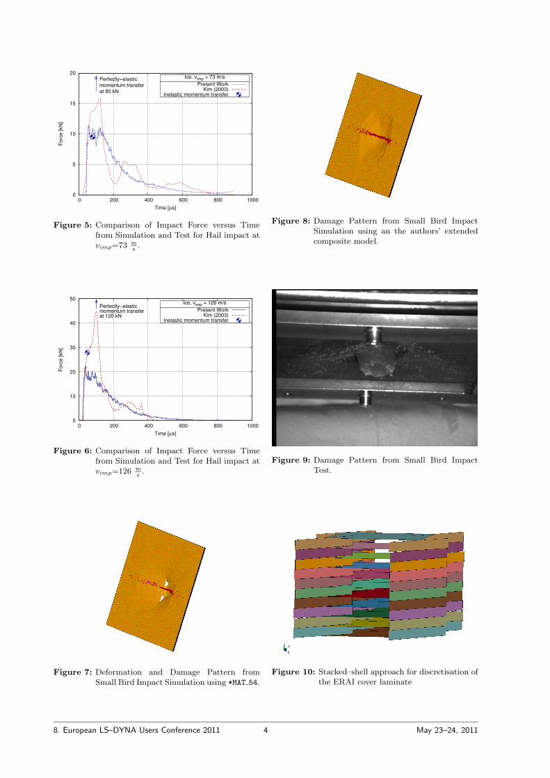
For verification, rresults from impact simulationsof a 42 mm ice sphere on a rigid surface [3] werecompared to test results by Kim [4]. Figure 5 andFigure 6 show a comparison of impact force versustime from simulation and test for hail impact atvimp=73 m
s and vimp=126 ms , respective.
The results from simulation and test differ ratherstrongly. For assessment of reliability, plausibility ofthe respective data was checked through compari-son with expected maximum forces from momentumtransfer. Under the assumption that the process canbe idealised rather as ineastic than as elastic, goodcorrelation was achieved for an impact velocity of73 m
s and still a reasonable one for an impact ve-locity of 126 m
s . Possibly, the results by Kim wereinfluenced by some oscillatory problems in the da-ta acquisition equipment. Should this presumptionturn out to be true, it would indicate high poten-tial for replacing testing of components by numeri-cal simulations. While the results presented here asa first attempt look quite promising, further test-sing throughout the entire range of temperature andstrain rate is necesary in order to improve reliability.
2.3 ERAI Cover
Previous bird impact simulations [1, 2] had shownthe necessity of taking into account effects of dy-namic loading on composite materials. A materialmodel having some capabilities was developed [5],implemented[6] and verified[7].
As an illustrative example for the effects of dyna-mic loading of CFC, Figure 7 and Figure 8 show thedeformation and damage pattern from small birdimpact simulation using *MAT 54 and the authors’extended composite model in comparison to the da-mage pattern from small bird impact test in Figure9.
An appropriate representation of failure in the la-minate is essential for obtaining realistic behaviourof the ERAI cover. In user–defined material modelsdefinition of erosion criteria is somewhat cumberso-me — at least at the authors’ level of experience.Given the choice of element erosion after failurein one integration point or no element deletion atall, the authors picked the second option. In con-sequence, the laminate had to be modeled in a so–called stacked–shell approach, i. e. every unidirectio-nal (UD) layer of the laminate had to be discretisedby a layer of shell elements. The respective layers
were connected by beam elements. Figure 10 showsa unit cell of the Finite Element (FE) mesh for theERAI cover.
3 Simulation Results
Figure 11 shows the deformation sequence a con-secutive impact of two hail stones. A delaminationpattern resulting from this impact loadcaseis shownin Figure 12.
As the extent of delamination was rather minorand no fibre failure occurred in the simulation, theresults were deemed good enough to grant an initialflight clearance. For a final certification, hail impacttests are still necessary. Especially, further testingof composites under high strain–rate loading at lowtemperatures is necessary for improvement of mate-rial models as well as for enhanced reliability of therespective imput parameters.
4 Summary and Outlook
Hail impact simulations have been performed for in-itial flight clearance of a CFC cover. Compared toa conventional testing approach, a remarkable re-duction in cost and duration has been achieved. Forcomposite parts, the authors took benefit from theopprtunities of implementig user–defined materialmodels in LS–DYNA. For modeling of hail stones,*MAT JOHNSON-COOK was chosen. Considering the si-milarity of recristalisation near melting temperaturewith respect to its effects on strength both for sweetwater ice as well as for some metals, an extension ofthe materalmodelcould be beneficiary.
For improvement of both a better understandingof material behaviour as well as for improvedreliability of parameters for existing materialmodels, extensive testing of coupon–size specimensin a wide range of strain–rate and temperature isadvisable.
Acknowledgements
The authors would like to thank Patrick Zillmer[3],Paul Neumann[8] and Annika Heutling[9] for theircontribution through their Semester Projects aswell as Matthaus Wieja[7] for support through hisDiploma Thesis.
8. European LS–DYNA Users Conference 2011 2 May 23–24, 2011

References
[1] P. Starke, G. Lemmen, K. DrechslerValidierung von Verfahren fur die numerischeSimulation von Vogelschlag4. LS–DYNA Anwenderforum 2005Bamberg, GermanyOctober 20–21, 2005
[2] P. Starke, L. MitterleitnerSome Applicatons of LS–OPT to Bird Impact-simulations6th European LS–DYNA Users’ ConferenceGothenburg, SwedenMay 29–30, 2007
[3] P. ZillmerSemester ProjectUniversitat der Bundeswehr, Neubiberg2009
[4] Hyonny Kim, Douglas A. Welch, KeithT. KedwardExperimental investigation of high velocity iceimpacts on woven carbon/ epoxy composite pa-nelsComposites Part A, 34, 25–412003
[5] P. StarkePhD Thesis (pending)2007
[6] F. MayerMSc Thesis2008
[7] M. WiejaDiploma ThesisUniversitat der Bundeswehr, Neubiberg2008
[8] P. NeumannSemester ProjectUniversitat der Bundeswehr, Neubiberg2010
[9] A. HeutlingSemester ProjectUniversitat der Bundeswehr, Neubiberg2008
Figure 2: Impactor Size and Impact Location for Sin-gle Hail Stone Impact Load Case.
Figure 3: Impactor Size and Impact Location for twoHail Stones consecutive Impact Load Case.
Figure 4: Impactor Size and Impact Location for tenHail Stones simultaneous Impact Load Case.
8. European LS–DYNA Users Conference 2011 3 May 23–24, 2011
0
5
10
15
20
0 200 400 600 800 1000
Forc
e [kN
]
Time [µs]
Perfectly−elasticmomentum transferat 80 kN
Ice, vimp = 73 m/s
Present WorkKim (2003)
Inelastic momentum transfer
Figure 5: Comparison of Impact Force versus Timefrom Simulation and Test for Hail impact atvimp=73 m
s.
0
10
20
30
40
50
0 200 400 600 800 1000
Forc
e [kN
]
Time [µs]
Perfectly−elasticmomentum transferat 120 kN
Ice, vimp = 126 m/s
Present WorkKim (2003)
Inelastic momentum transfer
Figure 6: Comparison of Impact Force versus Timefrom Simulation and Test for Hail impact atvimp=126 m
s.
Figure 7: Deformation and Damage Pattern fromSmall Bird Impact Simulation using *MAT 54.
Figure 8: Damage Pattern from Small Bird ImpactSimulation using an the authors’ extendedcomposite model.
Figure 9: Damage Pattern from Small Bird ImpactTest.
Figure 10: Stacked–shell approach for discretisation ofthe ERAI cover laminate
8. European LS–DYNA Users Conference 2011 4 May 23–24, 2011

Figure 11: Deformation sequence for the two hail stoneconsecutive impact
Figure 12: Delamination pattern for the two hail stoneconsecutive impact
8. European LS–DYNA Users Conference 2011 5 May 23–24, 2011