H Series - ALBRO HVAC SUPPLY
44
Installation, Operation and Maintenance Instructions Document 1105 Installation, Operation and Maintenance Instructions for H Series HW-M2 Series H-M2 Series HP-M2 Series FOR YOUR SAFETY: This product must be installed and serviced by a professional service technician, qualified in hot water heater installation and maintenance. Improper installation and/or operation could create carbon monoxide gas in flue gases which could cause serious injury, property damage, or death. Improper installation and/or operation will void the warranty. WARNING If the information in this manual is not followed exactly, a fire or explosion may result causing property damage, personal injury or loss of life. Do not store or use gasoline or other flammable vapors and liquids in the vicinity of this or any other appliance. WHAT TO DO IF YOU SMELL GAS • Do not try to light any appliance. • Do not touch any electrical switch; do not use any phone in your building. • Immediately call your gas supplier from a nearby phone. Follow the gas supplier's instructions. • If you cannot reach your gas supplier, call the fire department. Installation and service must be performed by a qualified installer, service agency, or gas supplier. OUT OF PRODUCTION
Transcript of H Series - ALBRO HVAC SUPPLY
Installation, Operation and Maintenance Instructions Document 1105
Installation, Operation andMaintenance Instructions for H Series
HW-M2 Series H-M2 Series HP-M2 Series
FOR YOUR SAFETY: This product must be installed and serviced by a professional service technician,qualified in hot water heater installation and maintenance. Improper installation and/or operation couldcreate carbon monoxide gas in flue gases which could cause serious injury, property damage, or death.Improper installation and/or operation will void the warranty.
WARNINGIf the information in this manual is not followed exactly, a fire or explosion may result causingproperty damage, personal injury or loss of life.
Do not store or use gasoline or other flammable vapors and liquids in the vicinity of this orany other appliance.
WHAT TO DO IF YOU SMELL GAS• Do not try to light any appliance.• Do not touch any electrical switch; do not use any phone in your building.• Immediately call your gas supplier from a nearby phone. Follow the gas supplier's
instructions.• If you cannot reach your gas supplier, call the fire department.
Installation and service must be performed by a qualified installer, service agency, or gassupplier.
OUT OF
PRODUCTION
Page 2 LAARS Heating Systems
TABLE OF CONTENTSSECTION 1.General Information1A. HW Series, H Series, HP Series .................. 41B. to the Installer: Before You Begin ................. 41C. Codes and Standards ................................... 51D. Unpacking the H Series ................................ 51E. Locating the H Series ................................... 51F. Clearances ................................................... 5
SECTION 2.Venting Options2A. Locating Unit With Respect to Ventilation .... 52B. Chimney Venting (USA Only) ....................... 62C. Installation .................................................... 62D. Alternate Venting Method (Canada Only) ..... 62E. Installing Stainless Steel
Horizontal / Vertical Venting ......................... 82F. Connecting special Gas Vent to H Series .... 82G. Appliance Joint Procedure
Part #2400-350............................................. 82H. Appliance Joint Procedure
Part #2400-352 or Z-Vent#02SVEPXX030 ........................................... 8
2I. Securing Special Gas Vent .......................... 8
SECTION 3.Venting and Air Source3A. The Direct Vent Kits
(part numbers 2400-326 or 2400-328) ....... 103B. Installing Direct Vent Kits ............................ 103C. Locating the Vent on an Outside Wall ........ 103D. Air Source For Combustion
(when not direct vented) ............................. 10
SECTION 4.Gas Connection to H Series4A. Gas Connection to H Series ....................... 114B. Domestic Water Piping ............................... 12
SECTION 5.Hydronic Heat Piping5A. Hydronic Heat Piping .................................. 125B. Feed Water Make-Up ................................. 125C. Hydronic Piping - HW Series ...................... 135D. Using In a Combined Hot Water
Heating and Chilled Water CoolingSystem ....................................................... 13
SECTION 6.Electrical Connections6A. Electrical Connections ................................ 16
SECTION 7.HP Mounting Piping7A. Wall Mounting Instructions
Paloma/Hytech Replacement ..................... 177B. New Wall Mount Installation ....................... 177C. Hydronic Systems Connections ................. 177D. Plumbing Accessories Installation .............. 177E. Gas Supply Connection .............................. 17
SECTION 8.HP Venting and Electrical8A. Venting the HP-M2-Series .......................... 178A-1. AGA ............................................................ 178A-2. CGA............................................................ 188B. Electrical Connections ................................ 188C. Manufactured Home (Mobile Home)
Appliance Installation Instructions .............. 188C-1. Appliance Mounting .................................... 18
SECTION 9.Check, Test and Start Up9A. Filling System ............................................. 199B. Firing Burner ............................................... 199C. Check Limit Control Operation ................... 199C-1. Operating and Low Limit Control HW-M2 ... 199C-2. Operating Control H-M2 ............................. 209C-3. Safety Limit Operation H(W)-M2 ................ 209C-4. Stack Switch Operation H(W)-M2............... 209D. Common Vent Test .................................... 209E. Lighting and Shutdown Instructions ........... 20
OUT OF
PRODUCTION

H Series Page 3
HW-M2 Series H-M2 Series HP-M2 SeriesHW-M2-130 H-M2-130* HP-M2-130*HW-M2-100 H-M2-100 HP-M2-100HW-M2-60 H-M2-60 HP-M2-60Integrated Hydronic Heating Hydronic Heating Only Hydronic Heating Onlyand Domestic Hot Water Appliance for Natural or Propane Gas. for Natural or Propane Gasfor Natural or Propane Gas. (Wall Hung).
* Field conversion only.
SECTION 10.Maintenance10A. Owner Care and Maintenance ................... 2010B. Service Maintenance .................................. 21
SECTION 11.Burner Input and BoilerComponent Descriptions11A. Adjusting Burner/Input ................................ 2111A-1. Measuring CO2* .......................................... 2111A-2. Measuring O2 .............................................. 2111B. Cleaning Combustion Chamber Coil .......... 2111C. Unit Pump................................................... 2211D. Gas Valve ................................................... 2211E. Safety Limit Switch ..................................... 2211F. Operating Control ....................................... 2211G. Igniter ......................................................... 2211H. Pressure Differential Switch ....................... 2211I. Transformer ................................................ 2311J. Low Limit (HW-M2 Series Only) ................. 2311K. Blower ........................................................ 2311L. Priority Relay - R1 (HW-M2 series only) ..... 2311M. Boiler Control .............................................. 2311N. Stack Switch ............................................... 2311O. Transfer Tank and Domestic Hot
Water Coil (HW-M2 series only) ................. 2311P. Thermostatic Union
(H(P)-M2-Series Only) ................................ 2311Q. Time Delay Relay (TDR)
(H(P)-M2-series only) ................................. 2411R. DHW Coil Replacement ............................. 2411S. Tank Replacement ..................................... 24
SECTION 12.Symptom Evaluations12A. Delayed Ignition .......................................... 2412B. Noisy Operation .......................................... 2512C. Insufficient Hot Water
(HW - M2 - series only) .............................. 2512D. High Gas Consumption
(see also Cross Contamination) ................. 2612E. Shortcycling
(H-M2, HP-M2 Series only) ........................ 2612F. Cross Contamination and
Combustion Related Short Cycling(units installed with Quick Vent) ................. 26
12G. Lock OutsIntegrated Boiler Control Lock Outs ........... 27
SECTION 13.Sequence of Operation
................................................................... 27
SECTION 14.Replacement Parts
................................................................... 37
SECTION 15.Trouble Shooting15A. S9301A Control Module ............................. 4115B. Quick Reference Trouble Shooter .............. 42
OUT OF
PRODUCTION
Page 4 LAARS Heating Systems
SECTION 1General Information
1A. HW Series, H Series, HP SeriesThe H Series boiler is a low pressure, hot water
boiler that is available in two (2) designconfigurations. The HW series provides domestic hotwater as well as hydronic space heating. It includes aninsulated storage tank through which boiler water iscirculated. A heat exchanger within the tank transfersheat from the boiler to the domestic hot water. The Hand HP series boilers are designed to provide hotwater for space heating, and can be plumbed to anindirect water heater to supply domestic hot water.
By replacing the air and the gas orifices, thebasic H Series boiler has the flexibility to operate oneither natural or LP gas and may be fired at 60,000,100,000 or 130,000 BTU/HR input. The H Series canbe direct vented by utilizing an optional concentricvent system that will provide outside air forcombustion. H(W)(P)-60,100 & 130 appliances mayalso be vented with 3" or 4" diameter stainless steelhorizontal / vertical venting as described on page 6.The maximum length shall not exceed 50 equivalentfeet of 3" diameter or 100 equivalent feet of 4"diameter. H(W)(P)-M2-130 appliances may also beconnected to a lined internal chimney.
The H Series features a forced draft, pre-mixedcombustion system. All air for combustion is suppliedwith the gas to the burner (flameholder). Both theintake air and the gas are metered through separateorifices before entering the combustion air blower.The blower forces the air/fuel mixture through theflameholder and into the combustion chamber. Themixture is ignited from the hot surface igniter andburns. Hot gases are forced out between the passes ofthe heat exchanger into the flue collector. Flue gasesare discharged into the outside atmosphere through thevent terminal, a chimney, horizontal or verticalalternate vent.
Model H(W)-M2-60 & H(W)-M2-100 UNITSMUST NOT BE CHIMNEY CONNECTED.
Installations with water containing 10 grains ofhardness or higher, must be installed with appropriatewater treatment.
1B. To the Installer: Before You BeginThe H Series is uniquely different from any
heating boiler you have installed in the past. It isimportant for you to take a few minutes to review thecontents of the Installation and Operating section ofthis manual before you begin installation. This willavoid making mistakes and causing confusion wheninstalling and operating the unit.
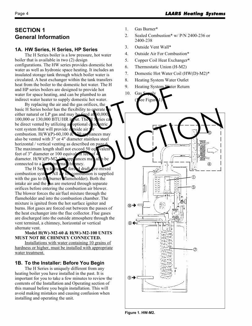
1. Gas Burner*2. Sealed Combustion* w/ P/N 2400-236 or
2400-2383. Outside Vent Wall*4. Outside Air For Combustion*5. Copper Coil Heat Exchanger*6. Thermostatic Union (H-M2)7. Domestic Hot Water Coil (HW(D)-M2)*8. Heating System Water Outlet9. Heating System Water Return10. Gas Supply
(*see Figure 1)
Figure 1. HW-M2.
OUT OF
PRODUCTION
H Series Page 5
1C. Codes and StandardsAll installations must be made in accordance
with: 1). The National Fuel Gas Code, ANSI Z223.1 -latest edition or 2). CAN/CGA - B149 “InstallationCodes for Gas Burning Appliances and Equipment” orwith the requirements of the local utility or otherauthorities having jurisdiction. Such applicablerequirements take precedence over the generalinstructions contained herein. All electrical wiring isto be done in accordance with 1). The NationalElectrical Code ANSI/NFPA70-latest edition or 2).The CSA standard C22.1 “Canadian Electrical Code -Part 1” and local codes.
All vent installations must be made inaccordance with: 1). Part 7, Venting of Equipment ofthe National Fuel Gas Code, ANSI 223.1- latestedition, or applicable provisions of the local buildingcodes or 2). CAN/CGA - B149
When required by the jurisdiction authority, theinstallations must conform to the American Society ofMechanical Engineers’ Safety Code for Controls andSafety Devices for Automatically fired Boilers, No.CSD-l.
1D. Unpacking the H Seriesa. Remove all packing and tie down materials.b. On HW models, remove three (3) shipping bolts
from underside of base.c. Make immediate claims ( to carrier ) if unit is
damaged.
1E. Locating the H SeriesThe H Series design is certified by the AGA and
CGA for installation on combustible flooring, inalcoves, basements, closets, or utility rooms. It mustnot be installed on carpeting. IF INSTALLED IN AFINISHED AREA, PROVISION SHOULD BEMADE FOR DRAINAGE OF ANY ACCIDENTALSPILLAGE OR LEAKAGE.
The location for the unit should be chosen withregard to venting dimensions, convenient access topiping, ventilation of operating components andaccessibility for service and cleaning.
The boiler shall be installed so that the gasignition system components are protected from water(dripping, spraying, rain, etc.) during applianceoperation or service (circulator replacement, controlreplacement, etc.).
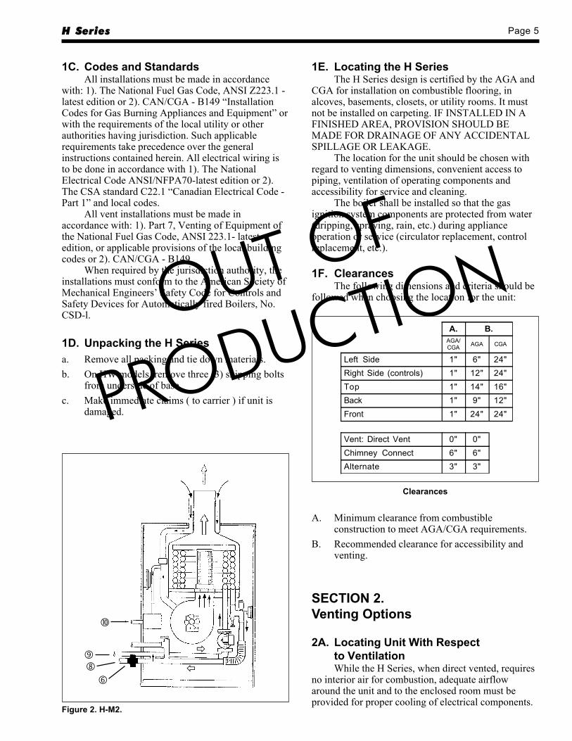
1F. ClearancesThe following dimensions and criteria should be
followed when choosing the location for the unit:
Figure 2. H-M2.
A. B.AGA/CGA AGA CGA
Left Side 1" 6" 24"Right Side (controls) 1" 12" 24"Top 1" 14" 16"Back 1" 9" 12"Front 1" 24" 24"
Vent: Direct Vent 0" 0"Chimney Connect 6" 6"Alternate 3" 3"
Clearances
A. Minimum clearance from combustibleconstruction to meet AGA/CGA requirements.
B. Recommended clearance for accessibility andventing.
SECTION 2.Venting Options
2A. Locating Unit With Respectto VentilationWhile the H Series, when direct vented, requires
no interior air for combustion, adequate airflowaround the unit and to the enclosed room must beprovided for proper cooling of electrical components.
OUT OF
PRODUCTION
Page 6 LAARS Heating Systems
2B. Chimney Venting (USA Only)Model H(W)-M2-60 and H(W)-M2-100 MUST
NOT BE CHIMNEY OR B-VENT CONNECTED.Model H(W)-M2-130 is a category l boiler and
may be vented in chimneys subject to the followingrequirements:
Chimney must be internally lined or “B” venttype. EXTERNAL OR UNLINED CHIMNEYS MAYONLY SERVE AS A CHASE for utilization ofstainless steel alternative venting providing no otherequipment is vented into it, or the chimney may havean approved liner installed into the flue.
Two (2) or more vent connectors, from eitherpower or natural draft units, may enter a common gasvent providing they conform to the requirements andtables of the National Fuel Gas Code, ANSI Z223.1/NFPA 54- latest edition, or applicable provision of thelocal building code. None may be connected toequipment with a positive vent pressure.
Locate unit as close to chimney as possible forshortest vent connector.
2C. InstallationDetermine height of chimney or B-Vent and
length of lateral run. Select vent connector diameterfrom:1). Table 1 or 2 of the National Fuel Gas Code,
ANSI Z223.1 / NFPA 54- latest edition (seeexcerpts), or
2). Table G-3 of the Can /CGA - B149 InstallationCode.Install an adaptor at the flue outlet of the unit to
step up to the diameter of the vent connector. Installelbow for vent connector, if required. This elbowshould be full size of the vent connector. DO NOTinstall a three (3) inch elbow between the flue outlet
on the unit and the adaptor. DO NOT use plastic ventpipe in any part of the chimney vent connection.
Install vent connector between elbow, if used,and chimney. Pitch vent connector up toward chimney¼" per foot of lateral run. Secure all joints withsheetmetal screws.
2D. Alternate Venting Method(Canada Only)The H Series may be vented vertically up
through a masonry chimney using a 4" diameter ULCCertification Flexible Stainless Steel Vent.
Observe the following requirements:1). The flexible vent must be run from the boiler up
through the entire chimney.2). The chimney must terminate with a suitable vent
cap.3). If chimney is exposed, the vent pipe should be
insulated.4). The vent pipe must be installed with a ¼" per
foot upward slope from the boiler to thechimney.
5). The vent pipe must be supported every 3' toprevent sagging.
6). All joints in the vent must be secured with atleast two corrosion resistant screws and sealedwith an approved silicone sealant and checkedfor gas tightness.
7). The vent system should be checked once a yearby a qualified serviceman.Note: Boiler may not be vented in common with
another gas appliance or be vented using B-vent.
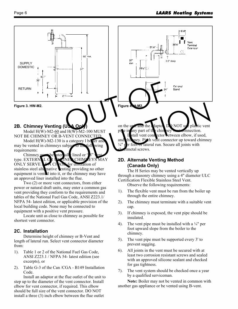
SUPPLYDOMESTIC
RETURN
Figure 3. HW-M2.
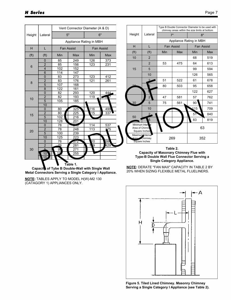
↑3.5" deep
Figure 4. H-M2.
OUT OF
PRODUCTION
H Series Page 7
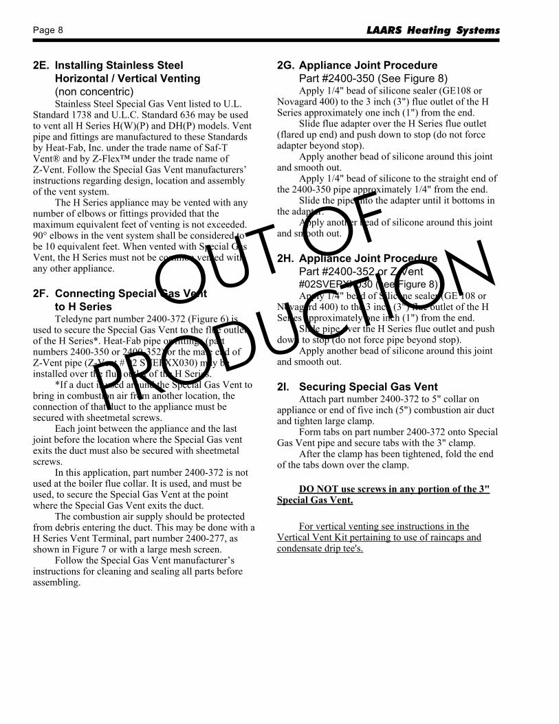
Height Lateral
Vent Connector Diameter (A & D)
5" 6"
Appliance Rating in MBH
H L Fan Assist Fan Assist
(ft) (ft) Min Max Min Max
6
0 85 249 126 3732 85 156 123 2314 102 1526 114 147
8
0 83 273 123 4122 83 176 121 2615 107 1688 122 161
10
0 82 293 120 4442 82 193 119 2875 105 18510
15
0 80 325 116 4992 80 225 115 3375 102 21610 128 201
20
0 78 346 114 5372 78 248 113 3755 100 23910 125 223
30
0 76 372 110 5842 76 281 109 4295 98 27110 122 25515
Table 1.Capacity of Tybe B Double-Wall with Single Wall
Metal Connectors Serving a Single Category I Appliance.
NOTE: TABLES APPLY TO MODEL H(W)-M2 130(CATAGORY 1) APPLIANCES ONLY.
Table 2.Capacity of Masonary Chimney Flue with
Type-B Double Wall Flue Connector Serving aSingle Category Appliance.
NOTE: DERATE "FAN MAX" CAPACITY IN TABLE 2 BY20% WHEN SIZING FLEXIBLE METAL FLUELINERS.
Height Lateral
Type B Double Connector Diameter to be used withchimney areas within the size limits at bottom
7" 8"
Appliance Rating in MBH
H L Fan Assist Fan Assist
(ft) (ft) Min Max Min Max
10 2 68 519
15
2 53 475 64 613
5 99 594
10 126 565
20
2 51 522 61 678
5 80 503 95 658
10 122 627
30
2 47 581 57 762
5 75 561 90 741
10 115 709
502 51 840
5 83 819Minimum InternalArea of ChimneySquare Inches
50 63
Maximum InternalArea of ChimneySquare Inches
269 352
Figure 5. Tiled Lined Chimney. Masonry ChimneyServing a Single Category I Appliance (see Table 2).
OUT OF
PRODUCTION
Page 8 LAARS Heating Systems
2E. Installing Stainless SteelHorizontal / Vertical Venting(non concentric)Stainless Steel Special Gas Vent listed to U.L.
Standard 1738 and U.L.C. Standard 636 may be usedto vent all H Series H(W)(P) and DH(P) models. Ventpipe and fittings are manufactured to these Standardsby Heat-Fab, Inc. under the trade name of Saf-TVent® and by Z-Flex™ under the trade name ofZ-Vent. Follow the Special Gas Vent manufacturers’instructions regarding design, location and assemblyof the vent system.
The H Series appliance may be vented with anynumber of elbows or fittings provided that themaximum equivalent feet of venting is not exceeded.90° elbows in the vent system shall be considered tobe 10 equivalent feet. When vented with Special GasVent, the H Series must not be common vented withany other appliance.
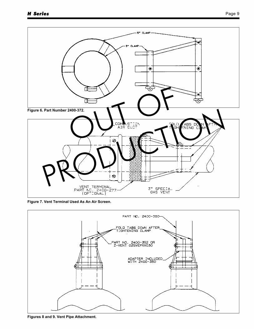
2F. Connecting Special Gas Ventto H SeriesTeledyne part number 2400-372 (Figure 6) is
used to secure the Special Gas Vent to the flue outletof the H Series*. Heat-Fab pipe or fittings (partnumbers 2400-350 or 2400-352) or the male end ofZ-Vent pipe (Z-Vent # 02 SVEPXX030) may beinstalled over the flue outlet of the H Series.
*If a duct is used around the Special Gas Vent tobring in combustion air from another location, theconnection of that duct to the appliance must besecured with sheetmetal screws.
Each joint between the appliance and the lastjoint before the location where the Special Gas ventexits the duct must also be secured with sheetmetalscrews.
In this application, part number 2400-372 is notused at the boiler flue collar. It is used, and must beused, to secure the Special Gas Vent at the pointwhere the Special Gas Vent exits the duct.
The combustion air supply should be protectedfrom debris entering the duct. This may be done with aH Series Vent Terminal, part number 2400-277, asshown in Figure 7 or with a large mesh screen.
Follow the Special Gas Vent manufacturer’sinstructions for cleaning and sealing all parts beforeassembling.
2G. Appliance Joint ProcedurePart #2400-350 (See Figure 8)Apply 1/4" bead of silicone sealer (GE108 or
Novagard 400) to the 3 inch (3") flue outlet of the HSeries approximately one inch (1") from the end.
Slide flue adapter over the H Series flue outlet(flared up end) and push down to stop (do not forceadapter beyond stop).
Apply another bead of silicone around this jointand smooth out.
Apply 1/4" bead of silicone to the straight end ofthe 2400-350 pipe approximately 1/4" from the end.
Slide the pipe into the adapter until it bottoms inthe adapter.
Apply another bead of silicone around this jointand smooth out.
2H. Appliance Joint ProcedurePart #2400-352 or Z-Vent#02SVEPXX030 (see Figure 8)Apply 1/4" bead of Silicone sealer (GE 108 or
Novagard 400) to the 3 inch (3") flue outlet of the HSeries approximately one inch (1") from the end.
Slide pipe over the H Series flue outlet and pushdown to stop (do not force pipe beyond stop).
Apply another bead of silicone around this jointand smooth out.
2I. Securing Special Gas VentAttach part number 2400-372 to 5" collar on
appliance or end of five inch (5") combustion air ductand tighten large clamp.
Form tabs on part number 2400-372 onto SpecialGas Vent pipe and secure tabs with the 3" clamp.
After the clamp has been tightened, fold the endof the tabs down over the clamp.
DO NOT use screws in any portion of the 3"Special Gas Vent.
For vertical venting see instructions in theVertical Vent Kit pertaining to use of raincaps andcondensate drip tee's.
OUT OF
PRODUCTION
H Series Page 9
Figure 6. Part Number 2400-372.
Figure 7. Vent Terminal Used As An Air Screen.
Figures 8 and 9. Vent Pipe Attachment.
OUT OF
PRODUCTION
Page 10 LAARS Heating Systems
SECTION 3.Venting and Air Source
3A. The Direct Vent Kits(part numbers 2400-326 or 2400-328)When using the Direct Vent Kit, the H Series is a
sealed combustion unit. All of its air is drawn in fromthe outside through the 5" outer pipe. Flue gases arevented through the 3" vent pipe positioned inside the5" intake pipe. The hot flue gases are surrounded bythe intake flow of cooler outdoor air. This vent systemmay be installed through, and be in contact with,combustible materials.
3B. Installing Direct Vent KitsThe Direct Vent H Series is certified with a
maximum of 15 linear feet of vent pipe and one set ofelbows. Systems may be vented with a maximum ofthree sets of concentric elbows providing themaximum length is reduced by three linear feet foreach additional elbow set. Provide a minimum of 16"above the top of the boiler for vent installation andservicing. There are two vent kits available. Partnumbers 2400-326 and 2400-328 provides all of therequired materials. Part number 2400-326 for ventinstallations which require adjustable height andhorizontal run. This kit will permit vertical andhorizontal lengths of pipe from 2' or 4'. One footextensions and 2' to 4' extensions are available toincrease vent lengths to the maximum allowed.Additional sets of elbows are also available.
Part number 2400-328 provides all of therequired materials for vent installations which mayhave a fixed height of 11 inches and an adjustablehorizontal run of 2' - 4'. Accessories for P/N 2400-326also fit P/N 2400-328.
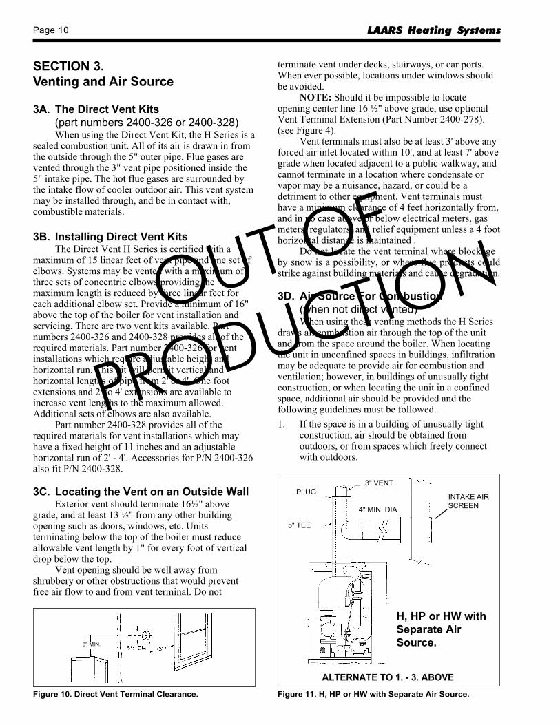
3C. Locating the Vent on an Outside WallExterior vent should terminate 16½" above
grade, and at least 13 ½" from any other buildingopening such as doors, windows, etc. Unitsterminating below the top of the boiler must reduceallowable vent length by 1" for every foot of verticaldrop below the top.
Vent opening should be well away fromshrubbery or other obstructions that would preventfree air flow to and from vent terminal. Do not
terminate vent under decks, stairways, or car ports.When ever possible, locations under windows shouldbe avoided.
NOTE: Should it be impossible to locateopening center line 16 ½" above grade, use optionalVent Terminal Extension (Part Number 2400-278).(see Figure 4).
Vent terminals must also be at least 3' above anyforced air inlet located within 10', and at least 7' abovegrade when located adjacent to a public walkway, andcannot terminate in a location where condensate orvapor may be a nuisance, hazard, or could be adetriment to other equipment. Vent terminals musthave a minimum clearance of 4 feet horizontally from,and in no case above or below electrical meters, gasmeters, regulators, and relief equipment unless a 4 foothorizontal distance is maintained .
Do not locate the vent terminal where blockageby snow is a possibility, or where flue products couldstrike against building materials and cause degradation.
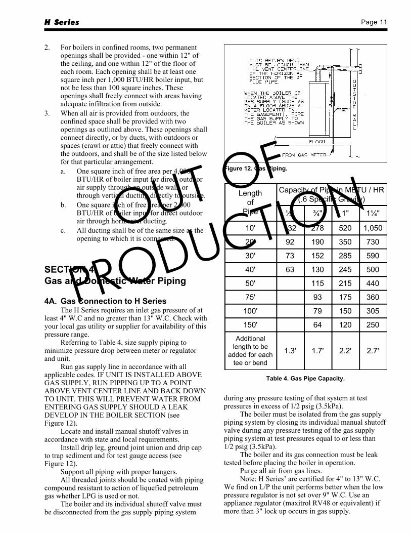
3D. Air Source For Combustion(when not direct vented)When using these venting methods the H Series
draws all combustion air through the top of the unitand from the space around the boiler. When locatingthe unit in unconfined spaces in buildings, infiltrationmay be adequate to provide air for combustion andventilation; however, in buildings of unusually tightconstruction, or when locating the unit in a confinedspace, additional air should be provided and thefollowing guidelines must be followed.1. If the space is in a building of unusually tight
construction, air should be obtained fromoutdoors, or from spaces which freely connectwith outdoors.
INTAKE AIRSCREEN
PLUG
5" TEE
3" VENT
4" MIN. DIA
H, HP or HW withSeparate AirSource.
ALTERNATE TO 1. - 3. ABOVE
Figure 11. H, HP or HW with Separate Air Source.
8" MIN.
Figure 10. Direct Vent Terminal Clearance.
OUT OF
PRODUCTION
H Series Page 11
2. For boilers in confined rooms, two permanentopenings shall be provided - one within 12" ofthe ceiling, and one within 12" of the floor ofeach room. Each opening shall be at least onesquare inch per 1,000 BTU/HR boiler input, butnot be less than 100 square inches. Theseopenings shall freely connect with areas havingadequate infiltration from outside.
3. When all air is provided from outdoors, theconfined space shall be provided with twoopenings as outlined above. These openings shallconnect directly, or by ducts, with outdoors orspaces (crawl or attic) that freely connect withthe outdoors, and shall be of the size listed belowfor that particular arrangement.a. One square inch of free area per 4,000
BTU/HR of boiler input for direct outdoorair supply through an outside wall, orthrough vertical ducting directly to outside.
b. One square inch of free area per 2,000BTU/HR of boiler input for direct outdoorair through horizontal ducting.
c. All ducting shall be of the same size as theopening to which it is connected.
SECTION 4.Gas and Domestic Water Piping
4A. Gas Connection to H SeriesThe H Series requires an inlet gas pressure of at
least 4" W.C and no greater than 13" W.C. Check withyour local gas utility or supplier for availability of thispressure range.
Referring to Table 4, size supply piping tominimize pressure drop between meter or regulatorand unit.
Run gas supply line in accordance with allapplicable codes. IF UNIT IS INSTALLED ABOVEGAS SUPPLY, RUN PIPPING UP TO A POINTABOVE VENT CENTER LINE AND BACK DOWNTO UNIT. THIS WILL PREVENT WATER FROMENTERING GAS SUPPLY SHOULD A LEAKDEVELOP IN THE BOILER SECTION (seeFigure 12).
Locate and install manual shutoff valves inaccordance with state and local requirements.
Install drip leg, ground joint union and drip capto trap sediment and for test gauge access (seeFigure 12).
Support all piping with proper hangers.All threaded joints should be coated with piping
compound resistant to action of liquefied petroleumgas whether LPG is used or not.
The boiler and its individual shutoff valve mustbe disconnected from the gas supply piping system
Figure 12. Gas Piping.
Lengthof
Pipe
Capacity of Pipe in MBTU / HR(.6 Specific Gravity)
½" ¾" 1" 1¼"
10' 132 278 520 1,050
20' 92 190 350 730
30' 73 152 285 590
40' 63 130 245 500
50' 115 215 440
75' 93 175 360
100' 79 150 305
150' 64 120 250
Additionallength to be
added for eachtee or bend
1.3' 1.7' 2.2' 2.7'
Table 4. Gas Pipe Capacity.
during any pressure testing of that system at testpressures in excess of 1/2 psig (3.5kPa).
The boiler must be isolated from the gas supplypiping system by closing its individual manual shutoffvalve during any pressure testing of the gas supplypiping system at test pressures equal to or less than1/2 psig (3.5kPa).
The boiler and its gas connection must be leaktested before placing the boiler in operation.
Purge all air from gas lines.Note: H Series’ are certified for 4" to 13" W.C.
We find on L/P the unit performs better when the lowpressure regulator is not set over 9" W.C. Use anappliance regulator (maxitrol RV48 or equivalent) ifmore than 3" lock up occurs in gas supply.
OUT OF
PRODUCTION
Page 12 LAARS Heating Systems
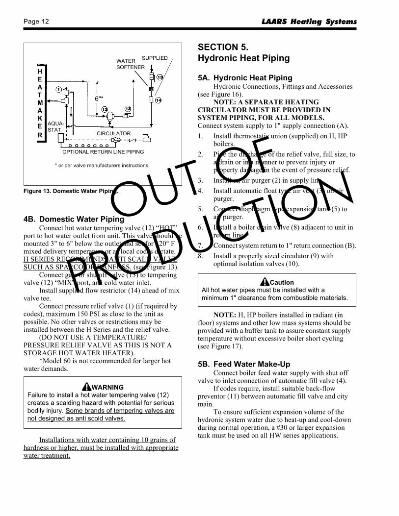
4B. Domestic Water PipingConnect hot water tempering valve (12) “HOT”
port to hot water outlet from unit. This valve should bemounted 3" to 6" below the outlet and set for 120° Fmixed delivery temperature or as local codes dictate.H SERIES RECOMMENDS ANTI SCALD VALVESUCH AS SPARCO OR DANFOSS. (see Figure 13).
Connect gate or shutoff valve (13) to temperingvalve (12) “MIX” port, and cold water inlet.
Install supplied flow restrictor (14) ahead of mixvalve tee.
Connect pressure relief valve (1) (if required bycodes), maximum 150 PSI as close to the unit aspossible. No other valves or restrictions may beinstalled between the H Series and the relief valve.
(DO NOT USE A TEMPERATURE/PRESSURE RELIEF VALVE AS THIS IS NOT ASTORAGE HOT WATER HEATER).
*Model 60 is not recommended for larger hotwater demands.
WARNINGFailure to install a hot water tempering valve (12)creates a scalding hazard with potential for seriousbodily injury. Some brands of tempering valves arenot designed as anti scold valves.
Installations with water containing 10 grains ofhardness or higher, must be installed with appropriatewater treatment.
SECTION 5.Hydronic Heat Piping
5A. Hydronic Heat PipingHydronic Connections, Fittings and Accessories
(see Figure 16).NOTE: A SEPARATE HEATING
CIRCULATOR MUST BE PROVIDED INSYSTEM PIPING, FOR ALL MODELS.Connect system supply to 1" supply connection (A).1. Install thermostatic union (supplied) on H, HP
boilers.2. Pipe the discharge of the relief valve, full size, to
a drain or in a manner to prevent injury orproperty damage in the event of pressure relief.
3. Install an air purger (2) in supply line.4. Install automatic float type air vent (3) on air
purger.5. Connect diaphragm type expansion tank (5) to
air purger.6. Install a boiler drain valve (8) adjacent to unit in
return line.7. Connect system return to 1" return connection (B).8. Install a properly sized circulator (9) with
optional isolation valves (10).
CautionAll hot water pipes must be installed with aminimum 1" clearance from combustible materials.
NOTE: H, HP boilers installed in radiant (infloor) systems and other low mass systems should beprovided with a buffer tank to assure constant supplytemperature without excessive boiler short cycling(see Figure 17).
5B. Feed Water Make-UpConnect boiler feed water supply with shut off
valve to inlet connection of automatic fill valve (4).If codes require, install suitable back-flow
preventor (11) between automatic fill valve and citymain.
To ensure sufficient expansion volume of thehydronic system water due to heat-up and cool-downduring normal operation, a #30 or larger expansiontank must be used on all HW series applications.
HEATMAKER
12
1
13
13
14
15
CIRCULATOR
OPTIONAL RETURN LINE PIPING
AQUA-STAT
WATERSOFTENER
SUPPLIED
6"*
* or per valve manufacturers instructions.
Figure 13. Domestic Water Piping.OUT OF
PRODUCTION
H Series Page 13
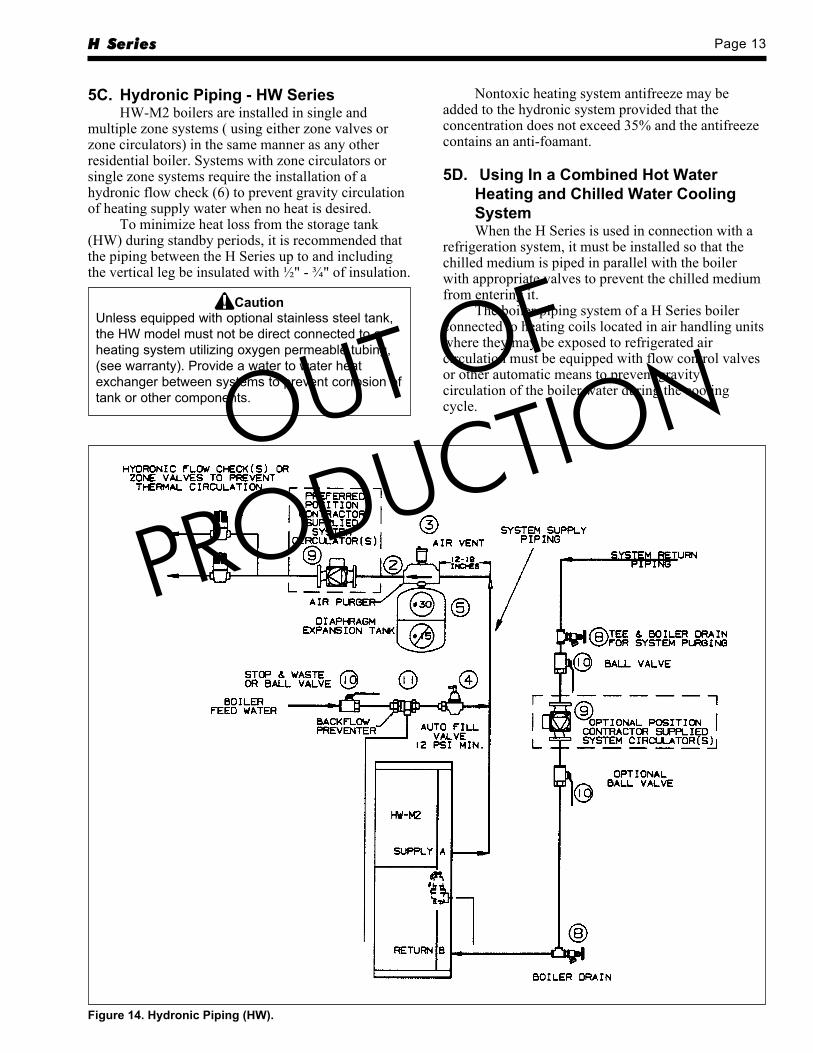
5C. Hydronic Piping - HW SeriesHW-M2 boilers are installed in single and
multiple zone systems ( using either zone valves orzone circulators) in the same manner as any otherresidential boiler. Systems with zone circulators orsingle zone systems require the installation of ahydronic flow check (6) to prevent gravity circulationof heating supply water when no heat is desired.
To minimize heat loss from the storage tank(HW) during standby periods, it is recommended thatthe piping between the H Series up to and includingthe vertical leg be insulated with ½" - ¾" of insulation.
CautionUnless equipped with optional stainless steel tank,the HW model must not be direct connected to aheating system utilizing oxygen permeable tubing,(see warranty). Provide a water to water heatexchanger between systems to prevent corrosion oftank or other components.
Nontoxic heating system antifreeze may beadded to the hydronic system provided that theconcentration does not exceed 35% and the antifreezecontains an anti-foamant.
5D. Using In a Combined Hot WaterHeating and Chilled Water CoolingSystemWhen the H Series is used in connection with a
refrigeration system, it must be installed so that thechilled medium is piped in parallel with the boilerwith appropriate valves to prevent the chilled mediumfrom entering it.
The boiler piping system of a H Series boilerconnected to heating coils located in air handling unitswhere they may be exposed to refrigerated aircirculation must be equipped with flow control valvesor other automatic means to prevent gravitycirculation of the boiler water during the coolingcycle.
Figure 14. Hydronic Piping (HW).
OUT OF
PRODUCTION
Page 14 LAARS Heating Systems
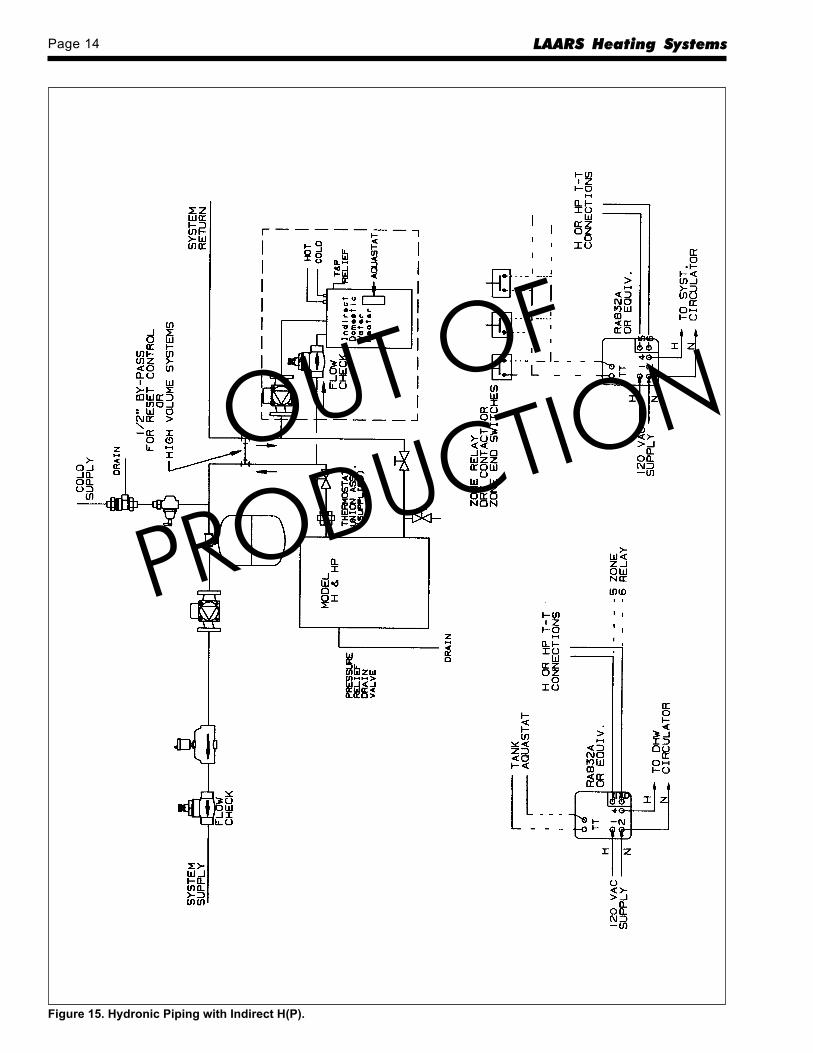
Figure 15. Hydronic Piping with Indirect H(P).
OUT OF
PRODUCTION
H Series Page 15
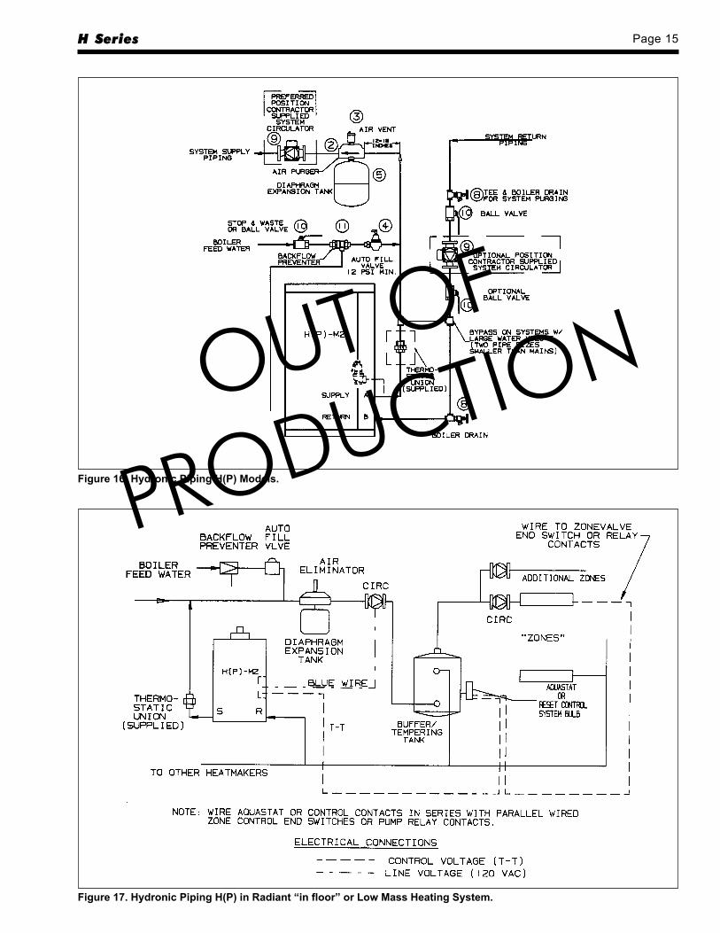
Figure 16. Hydronic Piping H(P) Models.
Figure 17. Hydronic Piping H(P) in Radiant “in floor” or Low Mass Heating System.
OUT OF
PRODUCTION
Page 16 LAARS Heating Systems
SECTION 6.Electrical Connections
6A. Electrical ConnectionsAll electrical wiring must conform to local codes
and/or the 1). National Electric Code or 2). CanadianElectrical Code - Part 1.
The unit must be electrically grounded inaccordance with the requirements of the authorityhaving jurisdiction or, in the absence of suchrequirement, with the 1). National Electrical Code.ANSI/NFPA NO.70- latest edition, or the CSAStandard C22.1 “Canadian Electrical Code - Part 1”.
Single pole switches, including those of safetycontrols and protective devices must not be wired in agrounded line.
All electrical connections are made in the fieldwiring box which is located on the right side of theunit.
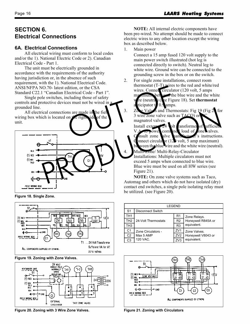
Figure 18. Single Zone.
Figure 19. Zoning with Zone Valves.
Figure 20. Zoning with 3 Wire Zone Valves. Figure 21. Zoning with Circulators
NOTE: All internal electric components havebeen pre-wired. No attempt should be made to connectelectric wires to any other location except the wiringbox as described below.1. Main power
Connect a 15 amp fused 120 volt supply to themain power switch illustrated (hot leg isconnected directly to switch). Neutral leg towhite wire. Ground wire can be connected to thegrounding screw in the box or on the switch.
2. For single zone installations, connect roomthermostat (T-T) wires to the red and white/redwires. Connect circulator (120 volt, 5 ampsmaximum) between the blue wire and the whitewire (neutral) (see Figure 18). Set thermostatanticipator to 0.9 amps.
3. Zone Valves and Thermostats: Fig 19 (Fig 20 for3 wire zone valve such as TACO) or DCmagnatrol valves.Install external 24 volt transformer of sufficientV.A. to power combined load of zone valves.Consult zone valve manufacturer’s instructions.Connect circulator (120 volt, 5 amp maximum)between the blue wire and the white wire (neutral).
4. Multi-Zone/ Multi-Relay-CirculatorInstallations: Multiple circulators must notexceed 5 amps when connected to blue wire.Blue wire must be used on all HW series (seeFigure 21).NOTE: On zone valve systems such as Taco,
Automag and others which do not have isolated (dry)contact end switches, a single pole isolating relay mustbe utilized. (see Figure 20).
LEGENDS1 Disconnect Switch
TH1 24-Volt Thermostats
R1 Zone Relays. Honeywell R845A or equivalent.
TH2 R2TH3 R3C1 Zone Circulators -
Max 5 AMP 120 VAC.
ZV1 Zone Valves. Honeywell V8043 or equivalent.
C2 ZV2C3 ZV3
OUT OF
PRODUCTION
H Series Page 17
SECTION 7.HP Mounting Piping
The Model HP-M2-Series may be used as eithera Paloma Pak/Hytech boiler replacement or as a newwall-mount installation. Carefully unpack HP unit.Read all installation instructions before starting theinstallation. Remove the Front removable jacket andfind the plumbing accessories package inside the unit.
7A. Wall Mounting InstructionsPaloma/Hytech ReplacementHang the HP-M2 as assembled from the
manufacturer onto the existing wall bracket. Do notremove the brackets which are attached to the newunit. If the existing wall bracket does not align withthe slotted mounting holes on the rear of the HP-M2,remove the old bracket from the wall and followinstructions for new wall mount below.
7B. New Wall Mount InstallationRemove the bolts, nuts and washers that secure
the two mounting brackets to the bottom and rear ofthe HP-M2 cabinet. Remove the U-channel spacerbracket from each wall bracket and discard. (Spacerbrackets are used only with original bracket in PalomaPak/Hytech retrofit installations)
Attach the included mounting template to theselected wall location. Mark and drill holes forappropriate mounting hardware at the templatespecified locations. Remove template from the walland securely affix the two wall brackets to the wallsurface with appropriate mounting hardware (providedby installer).
Lift the HP-M2 onto the wall brackets and re-assemble the bolts, nuts and washers to affix the unitonto the wall brackets.
NOTE: DO NOT REINSTALL THEU-CHANNEL SPACER BRACKETS WHENMOUNTING THE WALL BRACKETS DIRECTLYTO A WALL.
7C. Hydronic Systems ConnectionsThe H SERIES HP-M2 Series is supplied with
the necessary fittings to match the Paloma Pak supplyand return piping. If the original wall bracket iscompatible with the slotted mounting holes on the rearof the HP-M2, the supply and return pipe unionsattach directly to the existing piping. If the installationis new or if the old bracket is incompatible orunusable, the return and supply connections willrequire re-piping to match the HP-M2 connections.
7D. Plumbing Accessories Installation1) Attach boiler drain plumbing accessory to the
labeled “return” on the bottom of the HP-M2.
2) Separate Thermostatic Union Assembly halvesand thread the 1" nipple side to the labeled“supply” on the bottom of the HP-M2. Attach theremainder of the union assembly onto the tophalf of the union. Be sure to use appropriatethread sealers to assure leak-tight joints.
3) a. Where the HP-M2 is a direct replacementfor a PalomaPak/Hytech the installation iscompleted by connecting union halvestogether.
b. If the installation is new, refer to the pipingschematics and instructions on page 10 -12.
7E. Gas Supply ConnectionIf the installation is a direct retrofit, the gas
supply will require re-piping to connect to the HP-M2gas inlet. If the gas is supplied from below the unit, besure to run supply pipe to a point higher than the ventcenter line before connection to the unit gas valve.
On new installations refer to the gas pipingsection for gas pipe sizing and related information.
SECTION 8.HP Venting and Electrical
8A. Venting the HP-M2-SeriesThe HP-M2 may be vented using any of the
venting options available to the H(W)-M2-Series.These options include Direct Vent, Outside Airvented, Alternate horizontal/vertical venting (using“Special Gas Vent”) or internal lined or “B” Vent typechimneys.
MODEL HP-M2-60 & HP-M2-100 MUSTNOT BE CHIMNEY CONNECTED OR “B”VENT CONNECTED.
8A-1. AGAWhen used as a retrofit boiler vented into a
chimney or a “B” Vent, be sure to check current ventand vent connector sizing tables. Only units fired at130MBTU/hr may be vented with this option. Underno circumstances shall the HP-M2-60 be chimneyconnected or “B” vented using 3" vent or ventconnectors. The unit 3" vent collar must be increasedto a size which will accommodate the chimney systemfor the appropriate BTU/hr input of the boiler.
In the event the unit firing rate and masonrychimney parameters do not fall within therecommendations in the latest N.F.G.C.* chimneysizing tables, a flexible chimney liner may be utilizedin the chimney. Sizing capacity for metal chimneyliners may be obtained by 20% de-rating (or 80%) ofthe “fan max” capacity from B vent tables. See page 5for vent table excerpts.
*National Fuel Gas Code ANSI Z223.1 / NFPA 54.
OUT OF
PRODUCTION
Page 18 LAARS Heating Systems
8A-2. CGARefer to page 4 for Alternate Venting Method.
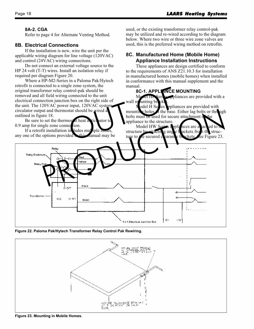
8B. Electrical ConnectionsIf the installation is new, wire the unit per the
applicable wiring diagram for line voltage (120VAC)and control (24VAC) wiring connections.
Do not connect an external voltage source to theHP 24 volt (T-T) wires. Install an isolation relay ifrequired per diagram Figure 20.
Where a HP-M2-Series in a Paloma Pak/Hytechretrofit is connected to a single zone system, theoriginal transformer relay control-pak should beremoved and all field wiring connected to the unitelectrical connection junction box on the right side ofthe unit. The 120VAC power input, 120VAC systemcirculator output and thermostat should be wired asoutlined in figure 18.
Be sure to set the thermostat heat anticipator to0.9 amp for single zone connection.
If a retrofit installation includes multiple zones,any one of the options provided in this manual may be
used, or the existing transformer relay control-pakmay be utilized and re-wired according to the diagrambelow. Where two wire or three wire zone valves areused, this is the preferred wiring method on retrofits.
8C. Manufactured Home (Mobile Home)Appliance Installation InstructionsThese appliances are design certified to conform
to the requirements of ANS Z21.10.3 for installationin manufactured homes (mobile homes) when installedin conformance with this manual supplement and themanual.
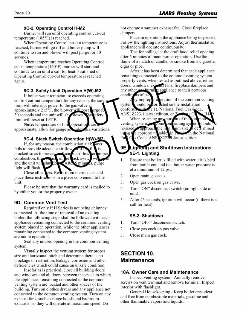
8C-1. APPLIANCE MOUNTINGModel HP Series appliances are provided with a
wall mounting bracket.Model H Series appliances are provided with
mounting holes in the base. Either lag bolts or throughbolts must be used for secure attachment of theappliance to the structure.
Model HW Series appliances are attached to thestructure by attaching angle brackets from the struc-ture to the secured clearance brackets. See Figure 23.
Figure 22. Paloma Pak/Hytech Transformer Relay Control Pak Rewiring.
Figure 23. Mounting in Mobile Homes.
OUT OF
PRODUCTION

H Series Page 19
SECTION 9.Check, Test and Start Up
9A. Filling System1. Open all supply and return valves.2. Fill heating system to minimum operating
pressure of 12 psig.3. Open bleed pet cock and bleed air from boiler
coil until a good stream of water comes out.(H(P)-M2 series), Item 8 on page 33.
4. Purge all lines by opening vents, or with flushingvalves.
5. Close gas valve.6. Turn on 120 volt power, and listen for unit
circulator to start. Unit will cycle off on lockout.7. Open all vents again to discharge any additional
air and close off after air is eliminated.8. System is now ready for operation.
9B. Firing Burner1. Be sure that system has been filled properly (see
above) and is leak tight.2. Open gas cock (s). Open manual gas shutoff
valve by turning to “on” position.3. Turn on main switch, and set thermostat to call
for heat. In approximately 2 seconds, blower willcome on.NOTE: Burner may not ignite on first attempt
because of air in gas lines. In this case, blower willstop after 5 minutes. Should this happen, turn off mainswitch. Wait 5 minutes and turn on main switch again.4. If burner fails to ignite after three attempts, refer
to Trouble Shooting Section 2, Service Manualor call service for troubleshooting.
CautionShould any pronounced odor of gas be detected, orif the gas burner does not appear to be functioningin a normal manner, close main shutoff valve, donot shut off switch, and contact your heatingcontractor, gas company, or factory representative.
5. You MUST check flame monitoring control(ignition system safety shutoff device).a. Close gas cock with burner operating.b. In 3 seconds, FLAME indicator light will
go out and blower will continue to run onpost purge cycle. Two additional attemptsto light will follow including pre-purge,igniter on, valve/flame on and post purge.(Ignition will not occur-gas off.)
c. Open gas cock. Switch unit “OFF” and then“ON” again. Burner should start after about45 seconds. It is recommended that the unitbe checked with a standard CO² or O²tester. Insert tester probe at least 6" intoexhaust pipe through outside vent terminal.Readings should be:CO2 - 8% to 8.5% (nat. gas)CO2 - 9% to 9.8% (LP gas)O2 - 7% to 4½%
6. Check Burner Input (other equipment off)a. Measure the time, in seconds, it takes to use
one cubic foot of gas.b. Divide the number of seconds into 3,600.c. Multiply the result by the heating value of
the gas to obtain BTU/HR input.Example: If it takes 36 seconds to use one cubicfoot of gas and the heating value of the gas is1,000 BTU/CU FT, (approx. natural gas value).INPUT = 3,600/36 x 1,000 = 100,000 BTU/HRInput RangesH(W)-M2-130 - 127,400 TO 132,600 BTU/HRH(W)-M2-100 - 98,000 TO 102,000 BTU/HRH(W)-M2-60 - 58,800 TO 61,200 BTU/HRBecause of the altitude and other minor
variations, it is possible the input will not fall withinthis range and the gas orifice must be replaced. Seechart in an orifice kit.
9C. Check Limit Control Operation9C-1. Operating and Low Limit
Control HW-M2When water temperature reaches low limit set
point (180°F) with no call for heat, H Series will shutdown.
Turn up the room thermostat. Boiler pump(inside jacket) will now run.
If water temperature is below operating controlcut out temperature (210°F) burner will fire.
When operating control cut-out temperature isreached (210°F) burner will go off, blower will postpurge for 30 seconds and the boiler pump and systemcirculator will continue to operate until roomthermostat is satisfied.
When water temperature drops below low limitcut-in temperature (150°F) and there is a continuedcall for heat, the system circulator will go off. Theboiler pump will continue to operate and the burnerwill remain on. When low limit cut-out temperature isreached (180°F) the system circulator will come on.
OUT OF
PRODUCTION
Page 20 LAARS Heating Systems
9C-2. Operating Control H-M2Burner will run until operating control cut-out
temperature (185°F) is reached.When Operating Control cut-out temperature is
reached, burner will go off and boiler pump willcontinue to run and blower will post purge for 30seconds.
When temperature reaches Operating Controlcut-in temperature (160°F), burner will start andcontinue to run until a call for heat is satisfied orOperating Control cut-out temperature is reachedagain.
9C-3. Safety Limit Operation H(W)-M2If boiler water temperature exceeds operating
control cut-out temperature for any reason, the safetylimit will interrupt power to the gas valve atapproximately 215°F, the blower will post purge for30 seconds and the unit will shut down. The safetylimit will reset at 195°F.
Note: temperature of limit operations are allapproximate; allow for gauge and tolerance variations.
9C-4. Stack Switch Operation H(W)-M2If, for any reason, the combustion air blower
fails to provide adequate air flow, or if the flue isblocked so as to prevent sufficient air flow for propercombustion, the contacts of the stack switch will openand the unit will shut down. After 5 minutes, purgelight will flash.
Close all covers. Reset room thermostats andplace these instructions in a place convenient to theunit.
Please be sure that the warranty card is mailed toby either you or the property owner.
9D. Common Vent TestRequired only if H Series is not being chimney
connected. At the time of removal of an existingboiler, the following steps shall be followed with eachappliance remaining connected to the common ventingsystem placed in operation, while the other appliancesremaining connected to the common venting systemare not in operation.
Seal any unused opening in the common ventingsystem.
Visually inspect the venting system for propersize and horizontal pitch and determine there is noblockage or restriction, leakage, corrosion and otherdeficiencies which could cause an unsafe condition.
Insofar as is practical, close all building doorsand windows and all doors between the space in whichthe appliances remaining connected to the commonventing system are located and other spaces of thebuilding. Turn on clothes dryers and any appliance notconnected to the common venting system. Turn on anyexhaust fans, such as range hoods and bathroomexhausts, so they will operate at maximum speed. Do
not operate a summer exhaust fan. Close fireplacedampers.
Place in operation the appliance being inspected.Follow the lighting instructions. Adjust thermostat soappliance will operate continuously.
Test for spillage at the draft hood relief openingafter 5 minutes of main burner operation. Use theflame of a match or candle, or smoke from a cigarette,cigar or pipe.
After it has been determined that each applianceremaining connected to the common venting systemproperly vents, when tested as outlined above, returndoors, windows, exhaust fans, fireplace dampers andany other gas burning appliance to their previousconditions of use.
Any improper operation of the common ventingsystem should be corrected so the installationconforms with the 1). National Fuel Gas Code,ANSI Z223.1 latest edition, or 2). Can / CGA - B149
When re-sizing any portion of the commonventing system, the common venting system should bere-sized to approach the minimum size as determinedusing the appropriate tables in Part 11 in the NationalFuel Gas Code, ANSI Z223.1-latest edition.
9E. Lighting and Shutdown Instructions9E-1. Lighting
1. Ensure that boiler is filled with water, air is bledfrom boiler coil and that boiler water pressure isat a minimum of 12 psi.
2. Open main gas cock.3. Open gas cock on gas valve.4. Turn “ON” disconnect switch (on right side of
unit).5. After 45 seconds, ignition will occur (if there is a
call for heat).
9E-2. Shutdown1. Turn “OFF” disconnect switch.2. Close gas cock on gas valve.3. Close main gas cock.
SECTION 10.Maintenance
10A. Owner Care and MaintenanceInspect venting system - Annually remove
screws on vent terminal and remove terminal. Inspectinterior with flashlight.
General Housekeeping - Keep boiler area clearand free from combustible materials, gasoline andother flammable vapors and liquids.
OUT OF
PRODUCTION
H Series Page 21
Keep boiler jacket louvers clear for propercooling of internal components.
Do not obstruct boiler room ventilation screensor grills.
10B. Service MaintenanceCleaning Heat Exchanger to be done by qualified
service person.1. Turn off electric and gas supplies and remove the
jacket.2. Remove the vent assembly and top cover.3. Remove the top half of the combustion chamber
by removing the three screws and nuts that clampthe top half to the bottom half, the clamp on theinduction tube and the 1/8" diameter balancelines.
4. Remove the top insulator cap by spreading theretainer.
5. Remove the igniter - to avoid damage duringcleaning.
6. Clean the finned tubing with a wire brush andvacuum all loose material from the combustionchamber. Wipe flameholder (burner) with a cleandry rag.
7. Replace all parts in the reverse order in whichthey were removed.
8. Restart the unit as indicated by the operatinginstructions plate.
SECTION 11.Burner Input and BoilerComponent Descriptions
11A. Adjusting Burner/InputThe H Series burner system is a pre-mixed,
forced combustion system. Outside air is drawnthrough the air orifice (located in the air inductionsystem) and mixed with the gas drawn in downstreamof the air orifice. The gas is metered through an orificelocated in the gas orifice union. All the air required forcomplete combustion comes into the system in thismanner.
Adjusting the input is limited to changing the gasorifice to achieve the proper input. The air orificecannot be altered and the gas valve pressure settingcannot be changed.
Before changing the gas orifice to correct input,service representatives should make the followingchecks:1. The pressure on the inlet side of the gas valve is
between 4" and 13" water column.
2. The pressure on the outlet side (manifold) of thegas valve and "T" above air orifice is betweennegative .05" and negative .35" water columnwith the unit operating.To increase the input, install larger diameter gas
orifice. Each size will change the input approximately5 C. F. H. Once the correct input has been achieved,the burner should be checked with an oxygen (O2) orcarbon dioxide (CO2) gas analyzer.
The unit should be in operation 5 minutes beforeadjusting input or taking CO2 or O2 readings. Thistime will allow for pre-heating of the intake air.
Insert the probe of the O2 or CO2 tester at least6" into the vent through the vent terminal. If CO2 isbeing measured, the readings should be between 8.0and 8.5 for natural gas and 9.0 and 9.8% for propane.If O2 is being measured, the readings should bebetween 7 and 6.
11A-1. Measuring CO2*When operating on natural gas, readings below
8.0 generally indicate a lean mixture (not enough gas).Readings above 9.25 generally indicate a rich mixture(too much gas). Inputs should be increased ordecreased to correct lean or rich mixtures.
NOTE: If the mixture is very rich (not enoughair for complete combustion), it is possible to get lowreadings on a CO2 analyzer. This situation does notoccur often but it can be detected if reading continuesto go lower as the input is increased. If this conditionis suspected, a CO test should be taken at the ventoutlet. Inputs must be reduced to correct high COreading and to bring CO2 readings to proper levels.
* The following numbers apply to natural gasonly. The range of operation for LP is 9.0 to 9.8.
11A-2. Measuring 02Readings above 7% indicate a lean mixture (not
enough gas). Readings below 4½% indicate a richmixture. Input should be increased to correct leanmixtures or decreased to correct rich mixtures.
11B. Cleaning Combustion Chamber Coil1. Turn off electric and gas supplies and remove the
jacket.2. Remove the vent assembly and top cover.3. Remove the top half of the combustion chamber
by removing the 3 screws and nuts that clamp thetop half to the bottom half, the clamp on the airorifice hose and the two clear plastic linesconnected to the "T" on the air induction elbow.
4. Remove the top insulator cap by spreading theretainer.
5. Remove the igniter.
OUT OF
PRODUCTION
Page 22 LAARS Heating Systems
6. Clean the finned tubing with a wire brush andvacuum all loose material from the combustionchamber.
7. Replace all parts in the reverse order in whichthey were removed.
8. Restart the unit as indicated by the lightinginstruction label.
11C. Unit PumpThe unit pump operates whenever there is a call
for heat or hot water.It is a wetted-rotor type pump and should always
be filled with water when it is operating so that it willcool properly.
If a pump change is required for any reason,valve off the boiler and drain approximately 1 or 2gallons of water from the unit. Turn off the maindisconnect switch and unplug the pump wires, removethe pump motor. The pump housing need not beremoved. The replacement pump motor should beinstalled in the reverse order from which the old pumpmotor was removed. After filling the system be sure tobleed the coil.
NOTE: If the pump motor is not defective thepump cartridge alone may be changed (Taco PumpsOnly).
11D. Gas ValveThe gas valve is a solenoid operated, negative
pressure regulated valve. The outlet pressure isregulated at minus 0.2 inches w.c. It is designed tooperate with supply pressures of 4-13 inches w.c.Within that range of supply pressures, the regulateddischarge pressure may vary from minus .05 to minus.35 inches w.c. The regulator is not adjustable and theeffect of this variation in discharge pressure is notsignificant. Because of the fixed regulator setting, gasflow must be adjusted by changing the gas orifice.
To remove the gas valve, shut off 120 volt powerand the master gas cock in gas line, loosen the nut onthe gas orifice union and remove the orifice union pluspiping to the gas valve. Disconnect the wires from thegas valve. The valve may now be unscrewed from theinlet piping. It may be necessary to deflect the inletpiping somewhat in order to clear the boiler jacket.After the valve has been removed, replace with a newvalve in the reverse order in which the old valve wasremoved. Do not over tighten the fittings into thevalve body as this may cause damage to the valve.
NOTE: When fueled by LP gas, H Seriesperform best with 9-10 in. W.C. supply pressure. If noother appliances are being supplied by the LP supplyset the low pressure regulator to 9-10 in. W.C.
11E. Safety Limit SwitchThe Safety Limit Switch has a fixed set point at
215°F. It will reset automatically.
To replace the switch , shut off the 120 voltpower and valve off the boiler, drain 1 or 2 gallons ofwater from the boiler and remove the nut which holdsthe safety limit bulb in the boiler discharge fitting.Remove the bulb from the fitting and remove the 2screws which hold the switch assembly to theelectrical control box. Disconnect the 2 wires from thequick connects at switch and remove the safety limitassembly. To replace, perform the same operations inreverse. Push the sensing bulb as far into the fitting aspossible before tightening sealing nut. No more than1/2" of sensing bulb should be visible afterinstallation. Fill the boiler and be sure to bleed the coilat the coil bleed petcock. Turn on disconnect switchand check boiler operation.
11F. Operating ControlThe Operating Control maintains boiler
discharge temperature between 170-210°F during thespace heating cycle. It has a fixed set point of 210°F(HW-M2 Series only) and a differential of 40°F,therefore, its contacts open at 210°F and they recloseat 170°F. If replacement is necessary, shut off the 120volt power and disconnect the wires to the sensor.Valve off and drain 1 or 2 gallons of water from theboiler and remove sensor. Install new sensor, refillboiler and bleed coil at coil bleed petcock. Checkboiler operation after installation of new OperatingControl. The Operating Control on the H(P)-M2 serieshas a fixed set point of 185°F. Its contacts open at185°F and they reclose at 160°F.
11G. IgniterThe igniter is a “glow bar” type silicon carbide
unit. It is energized whenever there is a call for heatand the red "IGNITER" light on the boiler control islit. After the igniter is switched off and the boilercontinues to run, the igniter functions as a flamesensor for the boiler control.
If the ignitor fails and must be replaced, alwaysinstall a new igniter gasket with the replacementigniter.
CautionIgnitor gets hot.
11H. Pressure Differential SwitchThe Pressure Differential Switch is a normally
open single pole switch which is designed to detectpump operation and water flow. To replace, turn offelectrical power & boiler feed water. Valve off anddrain 1 or 2 gallons of water from the boiler, unplugwires from the switch and remove switch. Install newswitch in reverse order. Refill boiler and bleed airfrom the coil bleed petcock. Turn on electrical powerand recycle system.
OUT OF
PRODUCTION
H Series Page 23
11I. TransformerThe control transformer accepts 120 VAC power
and provides 40 VA of 24 VAC power for the boilercontrol only. It is not capable of supplying controlpower for external devices such as zone valves. Theymust have their own separate power supply.
11J. Low Limit(HW-M2 Series Only)The H Series Mark 2 may be equipped with a
strap-on Low Limit. The Low Limit control performstwo functions. It controls the temperature of the waterin the transfer tank and it prevents the house circulatorfrom operating when insufficient tank watertemperature causes the domestic hot water deliverytemperature to drop below 140°F. The Low LimitControl has a fixed differential of 15°F and is set toturn the burner on at 140°F tank water temperatureand to turn it off when the sensor reaches 155°F.Because of the thermal lag in the sensor, the tankwater temperature will reach about 180°F before theburner actually is turned off. The boiler temperaturemay reach operating temperature due to this thermallag.
If replacement is necessary, shut off the 120 voltpower. Simply remove and attach wire for wire.Clamp the new Low Limit to the hot outlet pipe asclose to the domestic exchanger plate as possible andcover area with tank insulation blanket. Return boilerto service.
11K. BlowerThe Combustion Air Blower is a high head
centrifugal blower. It is designed to provide about 2"w.c. of suction at 30 CFM. This performance isnecessary to operate the gas valve reliably, toovercome induction system friction losses and toeliminate any sensitivity to wind striking the ventterminal. It is powered by a 120 volt motor whichdraws about 1.3 amps at rated load. It is powered bythe integrated boiler control whenever there is a callfor heat and 30 seconds thereafter. If a blower changeis required, turn off the 120 volt power and unplug thepower wires from the blower motor. Remove the threenuts from the blower discharge flange and the fournuts from the blower inlet flange. The blower maynow be deflected enough to permit its removal. Installthe new blower using new gaskets, in the reverse orderfrom which the old blower was removed. The fourinlet flange nuts, however, should only be finger tightinitially and then tightened with a wrench after allother operations have been completed. Thecombustion should be checked for correct air-fuelratio whenever the blower is replaced (see BurnerAdjustment).
11L. Priority Relay - R1(HW-M2 series only)The Priority Relay is a normally open single pole
relay which accepts a 24 VAC signal from the lowlimit aquastat and the T-T wires to provide 120 VACpower to the system circulator when the tanktemperature remains above 150°F.
11M. Boiler ControlThe Integrated Boiler Control Module controls
the combustion process, the gas valve, the igniter, theblower, the unit pump and the system circulator. Itprovides blower prepurge as well as burner flamesensing. When replacing the boiler control turn offdisconnect switch and press in tabs on each end ofplugs to remove from control. All plugs are colorcoded and it is not possible to miswire the control.
11N. Stack SwitchThe Stack Switch is a normally open single pole
switch which is operated by the pressure differenceacross the air orifice. It is set to close when a staticpressure difference of 1 in. w.c. is generated by thecombustion air blower. Its function is to prove airflowand to inhibit burner operation in the event of flue orchimney stoppage. The switch is wired directly to theboiler control. It is located on the inside of the jacketback panel adjacent to the boiler bracket.
11O. Transfer Tank and Domestic Hot Water Coil (HW-M2 series only)The transfer tank contains approximately 20
gallons of boiler water. It functions as an energystorage vessel to reduce boiler cycling on small outputheating zones and to provide heat for domestic hotwater through the domestic hot water (DHW) coilimmersed in it. The DHW coil may be removed fromthe tank if either tank or the DHW coil must bereplaced. The coil is secured to the tank with (6) -3/8"- 16 bolts which are replaceable if they are broken orstripped.
11P. Thermostatic Union (H(P)-M2-Series only)The thermostatic union is a 1¼" NPTF union
which has a thermostatic element on the inside. Theelement has two small bypass holes to allow somewater to flow into the system when the element isclosed. When the boiler first starts and cold systemwater is returning, the element is closed and boilerwater is recirculated back to the return until the supplywater reaches 160°F and the element opens. Toreplace the element shut off and drain the section ofthe system that the thermostatic union is installed in.Open the union and replace the element with a newone. The element should be installed so that its spring
OUT OF
PRODUCTION
Page 24 LAARS Heating Systems
and actuator are on the system side. Close union, openvalves, refill and bleed system, bleed coil at coil bleedpetcock and restart boiler.
11Q. Time Delay Relay (TDR) (H(P)-M2-series only)The Time Delay Relay controls the unit pump
and keeps it operating for approximately one minuteafter the blower post purge stops. Control voltage onthe TDR is 24 volts from the limit circuit. Thecontacts to supply pump power are 120 VAC. Theydelay on open one minute after the 24 volt controlvoltage is interrupted. Turn off disconnect switchbefore changing TDR.
11R. DHW Coil ReplacementShut off boiler feed water, domestic water supply
to coil and electrical power to boiler. Valve off systemand drain the water from the tank. Disconnect boilerdischarge union from coil fitting, remove relief valvedischarge piping and cut the horizontal hot and coldwater pipes about 6 inches away from plate.Disconnect and remove low limit sensor. Remove thesix coil retaining nuts and take out coil. Remove theold coil gasket and clean gasket sealing surface ontank. Remove the pressure relief valve from old coiland install in new coil assembly with thread sealingtape or pipe joint compound. Install new gasket inrecess on tank (if it doesn’t fit snugly in tank recessremove it and stretch it). Place new coil in tank andscrew on coil retaining nuts. Tighten nuts evenly toseat gasket properly. Do not over tighten. Make upboiler discharge union, fill boiler and check aroundgasket for leaks. If the coil plate is leak tight make uphot and cold water pipes with slip couplings andreassemble relief valve discharge piping. Connect andreinstall low limit sensor. Turn on domestic watersupply and electrical power. Bleed air from coil bleedpetcock and recycle boiler. Boiler fill pressure is 12PSI minimum.
11S. Tank ReplacementThe tank can be replaced by disconnecting the
DHW coil as explained above and unbolting the lowerpump flange bolts. Access to the tank is possible byremoving the jacket lower front panel. This is done byremoving the screws that hold the panel at the baseand by cutting an aluminum pop rivet on each side atthe top approximately 2 inches down. These rivetshold the lower front panel to the jacket back. A flatbladed tool like a putty knife is ideal for this purpose.Drive the blade down from the top in the creasebetween the jacket back and the lower front panel.This will cut the rivets. Remove the four screws thathold the electrical box and move it aside. The lowerfront panel may now be lifted up above the base andremoved. When the boiler is shipped from the factory
there are shipping bolts which hold the tank and thebase together. The installer was instructed to removethese bolts before installing the boiler. If this was donenothing will be holding the tank in place at this timeexcept the hydronic piping at the rear of the appliance.Remove the supply and return connections andremove the tank. Installation of the new tank is donein the reverse order. If the tank alone is being replacedit is easier to remove tank and coil together andchange the coil from the old tank to the new one whenboth are free of the jacket.
SECTION 12.Symptom Evaluations
12A. Delayed IgnitionPossible Causes - Time of occurrence
a. High lockups on LP - occurs on start-up.b. Gas valve regulation problem - occurs on start-up.c. Defective burner (flameholder) - occurs
primarily on burner shutdownd. Natural gas orifice in LP unit - occurs on start-up
High lock up pressures on LP fuel systems arethe most common cause of delayed ignitions on HSeries boilers. The high LP supply pressure resultsfrom improper second stage regulator selection or afaulty regulator.
It can be detected by measuring the gas supplypressure to the unit at the inlet pressure tap on the gasvalve. Use a water manometer or pressure gage with ascale reading of at least 25 in. W.C. or 15 oz/in².Install the pressure tap in the 1/8' NPTF plugged portlocated above the gas inlet port on the gas valve. Thegas supply to the boiler must be shut off beforemaking this connection. The H Series boiler isdesigned to operate with supply pressures of 4-13 in.W.C. (2.3 - 7.5 oz/in²). If supply pressure exceeds 13in. W.C. (7.5 oz/in²) with the boiler not operating it islikely that this is the cause of the delayed ignition.Lock up pressures must be measured when the boileris not operating and preferably immediately afterboiler shutdown.
Gas valve regulation problems can also causedelayed ignitions. To detect gas valve regulationproblems it is necessary to have an inclinedmanometer or a Magnehelic pressure gage. Thenormal gas valve regulator setting is - 0.2 in. W.C. Itis measured between the 1/8" NPTF plugged portmarked PRESS TAP on the gas valve and the barbedfitting above the air orifice coupling.
The pressure will be about -2.5 IN. W.C. whenthe blower is running (prepurge) before the gas valveopens. When the gas valve is energized and thesolenoid opens the pressure should rise to - 0.2 IN.W.C. This should happen smoothly without allowing
OUT OF
PRODUCTION
H Series Page 25
the pressure to go positive (above 0 IN. W.C.). If thepressure spikes positive when the solenoid opens thenthe gas valve regulator is faulty and may be the causeof the delayed ignition (assuming inlet tested OK).
A defective burner (flameholder) can cause adelayed ignition however not often. If the gas supplypressure and the gas valve are functioning properlyand the air and gas orifices are correct the burnershould be inspected. To inspect, remove the blowerand the burner will drop out of the bottom of thechamber. There should be no perforations other thanthe punched holes. When replacing the burner theinsulating pad must be on the top of it. If none was onthe burner when it was removed check to see if it felloff during burner removal and has stayed in thecombustion chamber. Never leave an insulating padlying in the combustion chamber as this can causeburner overheating and perforation.
12B. Noisy OperationThere are two principal sources of noisy
operation:a. Combustion - high pitched noise - whistle or hootb. Boiling (kettling) - lower frequency noise which
varies with temperature - moan.Combustion noise occurs at any boiler discharge
temperature and is heard the loudest at the flue outlet(especially on units with side wall venting). There aretwo basic causes for the noise, rich mixture and crosscontamination. To check for a rich mixture, it will benecessary to measure the percent O² or CO² in the flueproducts. O² readings lower than 4½ % or CO²readings higher than 9¼% (natural gas) and 10.8%(LP) will often cause combustion noise. To eliminatethe noise it will be necessary to install a smaller gasorifice so that the O² will rise above 4½% or the CO²will drop to 8½% (natural) or 9½% (LP).
Sometimes the readings are influenced by crosscontamination and a check for cross contaminationshould be done before changing orifices if it issuspected. A strong smell from the flue products isgenerally an indication. Check for cross contaminationusing the procedure listed in the index. If there is nocross contamination, reorificing should be done.
Boiling (kettling) may occur at boiler dischargetemperatures from 170°F to 210°F. The temperature atwhich it starts will vary from one installation toanother. The primary cause of the problem is poor heattransfer on the inside of the boiler coil. This may becaused by foaming of antifreeze in the system orscaling from the boiler water if no antifreeze ispresent.
There are many manufacturers of plumbing andboiler antifreezes. Plumbing antifreezes should neverbe used in a boiler system because they have noantifoamants in them. Not all boiler antifreezes have
an effective antifoamant either so the noise may existwith boiler antifreezes also.
The cure for the boiling noise is the sameregardless of the cause. However, if antifreeze in thesystem is suspected of being the cause, theconcentration and type should be investigated beforeattempting to eliminate the noise. The most effectivemeans of cleaning the combustion coil utilizes thesiphon cleaning method. Concentrations of antifreezeshould be kept as low as possible because antifreezewill reduce heat transfer and efficiency.
Many times it is difficult to determine if thenoise is combustion or boiling related. The best clue iswhen in the cycle the noise appears and if itsfrequency changes with boiler discharge temperature.Combustion noises always have the same frequency,however, their volume may change from the time thatthe burner first fires to the time that it shuts off.Boiling noises have a frequency that varies with boilerdischarge temperature and sometimes they willdisappear completely at higher temperatures justbefore the boiler goes off on limit. Vibration of theboiler pressure gage needle may also occur withboiling noises.
12C. Insufficient Hot Water (HW - M2 - series only)Possible Cause:
a. No Flow Restrictorb. Low limit Failurec. Incorrect Wiring of System Circulatord. No Flow Check in System Supplye. Coil Contamination
The most common cause for insufficient hotwater complaints results from failure to install a flowrestrictor. If there is no flow restrictor water passesthrough the coil at a greater volume than the boileroutput is capable of heating to the desired temperaturerise.
Failure of the low limit to operate within itsnormal calibration points will have the same effect asincorrect system circulator wiring.
Incorrect wiring for the system circulator canalso cause the problem. If the blue wire in the fieldwiring box is not used to control the circulator orcirculators then the low limit cannot prevent boilerwater temperature from dropping to a point that isinsufficient to provide enough heat for the domestichot water coil. The blue wire interrupts power to thesystem circulator through the priority relay R-1. R-1 iscontrolled by the low limit which should limitminimum tank temperature to 140°F.
Flow checks in single zone systems andmultizone systems with zone circulators preventgravity circulation of heated boiler water from the
OUT OF
PRODUCTION

Page 26 LAARS Heating Systems
transfer tank. If no flow check exists or if an existingflow check is left in the manual (open) position, heatleaves the bottom of the tank by gravity circulation.
Because of stratification in the tank when thepump is off, the water around the low limit sensor willremain hot and the boiler will not replace the heat thatis lost. When domestic hot water is turned on therewill be a short draw of domestic hot water and then,when the unit pump comes on to start the boiler, thecold water in the bottom of the tank will be mixedwith the hot water at the top and mix temperature willbe too low to provide adequate domestic hot water andit will turn cold. If this is the suspected cause feel thetemperature of the piping after the flow check whenthe heating system has not been calling for awhile. Ifthe piping is hot, there is flow past the flow checkwhich may be causing the problem.
Coil scaling may occur in some areas of thecountry where there are high concentrations ofminerals in the water. These minerals may causefouling of the domestic hot water coil over anextended period of time (lime build up) or they may inrare instances cause a problem in less than a year ofoperation. The minerals which react quickly (mostlymagnesium) in well systems cause a slime on theinside of the coil which prevents adequate heattransfer. These minerals must be filtered out by aspecial incoming water filter or inhibited to protect thecoil and also to provide acceptable water quality. Theminerals contained in public water systems whichaccumulate in the coil over long periods of time maybe removed when necessary by flushing the coil withcleaner such as “Unlime” or “Sizzle”. These productsare also effective in cleaning a coil that is fouled bymagnesium.
12D. High Gas Consumption (see also Cross Contamination)Improper burner operation caused by incorrect
air/fuel ratio (CO2 or O2 out of the specified range)will cause high gas consumption. It is most noticeableon LP fired units with low CO2 or high O2, however,units operating on LP or natural gas with incorrect air/fuel ratios will not provide their best efficiency. If nocombustion analyzing equipment (CO2 or O2) isavailable an indication of the air/fuel ratio can begotten by briefly sniffing the flue gases. Whenrunning properly the Heat Maker’s flue gases shouldhave little smell. If they have a strong piercing smellthe gas orifice is probably too small. Do not attempt todo reorificing without an O2 or CO2 kit.
12E. Shortcycling (H-M2, HP-M2 Series only) (see also Cross Contamination)Possible Causes:
a. No system circulator - low system water flowb. Small zones - high zone return temperature
The most common causes of short cycling ofH(P)-M2- Series and other low mass boilers isinsufficient hydronic system water flow or smallzones. With H Series this is sometimes caused by theinstaller’s failure to install a system circulator asrequired in the Installation and Operating Instructions.
The result of low flow is very rapid temperaturerise in the boiler. Sometimes the rise is so fast that theoperating control will not operate before the safetylimit operates. Boiler will reset following cool downof safety limit thermo element.
Another cause of short cycling is a result ofsystem design. If one zone in a zoned system has avery small output, the boiler will only be on for a shorttime (when that zone is operating alone) before thereturn water comes back to the boiler at a temperaturewhich will cause the operating control contacts toopen. If this situation causes very rapid cycling it maybe necessary to only operate the small output zonewhen another zone is calling. This can be done mostsimply (on systems using zone valves) bydisconnecting the end switch wire on the small outputzone one so that the boiler will not be started unlessanother zone is calling. This approach eliminates theneed for time consuming repiping. If the on cycles areat least 1½ minutes long then the short cycling will notbe a problem.
12F. Cross Contamination and Combustion Related Short Cycling (units installed with Quick Vent)Boiler short cycling, nuisance lockouts and
objectionable flue gas odors, may be caused byleakage of flue products into the combustion airstream. This results from poorly sealed joints in theinner (3") pipe. The symptom of this problem iscontinual restarts without a lockout occurring. The“VALVE/FLAME” lite will be on for only a shorttime (but more than 6 seconds) before the post purgestarts. This condition is generally seen on newinstallations; however, it is possible that a poorlyassembled flue pipe could come apart and cause thesame effect. Cross contamination can best be detectedwith a CO2 analyzer (Bacharach® kit for example).Remove the stack switch tube from the “tee” fittingabove the air orifice and connect the sampling tube ofthe analyzer to the "tee". Run boiler and check CO2. Ifthere is any measurable CO2, cross contaminationexists somewhere in the flue system. If the boiler willnot operate long enough to get a CO2 sample it is
OUT OF
PRODUCTION
H Series Page 27
possible to check for cross contamination in anotherway. Loosen the top clamp on the air duct couplingand remove the gas balance line from the “Teefitting”. Lift up the air induction elbow and twist it tothe side so that air from the space around the boilercan be drawn into the air duct coupling (do not disturbthe air orifice in the coupling). Cover the air inductionelbow with your hand or plug it with a rag and restartthe boiler. If no short cycling occurs there is a leak inthe 3" flue pipe which must be corrected. Do not leavethe boiler operating in this manner. Reassemble the airduct after removing plug (rag) and connect the balanceline and stack switch tubes. Disassemble flue and fixleak.
12G. Lock Outs Integrated Boiler Control Lock OutsPossible Causes
a. Cross Contaminationb. Moisture in Combustion Chamberc. Gas Valve Malfunctiond. Poor combustione. Boiler control malfunctionf. Control contact failure
1). Stack Switch2). Operating Control
g. Failure of air sourceh. Igniter failure
If cross contamination is suspected see “CrossContamination” and check for it. One percent CO2 inthe air duct can cause nuisance lockouts.
Moisture in the combustion chamber will alsocause lock outs by weakening the flame signal to theboiler control. It should be suspected if the boilertemperature does not rise above 160°F during longperiods of operation. This condition can be caused bya defective thermostat in the thermostatic union ofH(P)-M2-series boilers (or the omission of thethermostatic union at installation) or an improperlywired system circulator on HW-M2-series boilers. Onsidewall vented units moisture can get into thecombustion chamber from a flue pipe that is pitchedincorrectly (back toward the boiler without acondensate trap). Quick Vented systems shouldalways pitch down from the boiler.
A defective gas valve (one that doesn’t alwaysopen properly) can cause a nuisance lockout howeveroccurrences of this are rare.
A more common cause of nuisance lockouts ispoor combustion. If there is an odor in the flue gases,this should be suspected. Check CO2 or O2 todetermine if combustion is within limits. Poorcombustion causes a weak flame signal to the burnercontrol and lock outs may result.
If combustion is within limits and none of thecauses mentioned above seems to be the cause of thelockout it is possible that the boiler control may bedefective.
SECTION 13.Sequence of Operation
On a call for heat from the room thermostat onH(W)-M2 series boilers (or the low limit on the HW-M2 series), the pump operates and the boiler control isenergized through the operating control, pressureswitch and the safety limit. It checks to ensure that thestack switch contacts are open and then energizes theblower. The blower starts and the air pressureincreases until the stack switch contacts close and thered “PURGE” light lights. The pump and blowercontinue to run and for 15 seconds the red “PURGE“light stays on. Following that the red “PURGE“ lightgoes out, the red “igniter” light lights and the igniterheats for 20 seconds. At the end of the 20 seconds thered "VALVE\FLAME" light is lit and the gas valveis energized. For 2 seconds the valve and igniter areenergized and burner will ignite. Following this theigniter is deenergized and the red “IGNITER” lightgoes out and the pump and blower continue to run andthe burner operates under the supervision of the boilercontrol. If for any reason the full sequence iscompleted and the burner doesn’t ignite, the sequencewill be repeated after a blower “on “ time of 45seconds (30 seconds post purge and 15 secondsprepurge for the next cycle). During this part of thesequence the igniter remains on for 30 seconds and thebalance of the sequence is unchanged. If no ignitionoccurs again a third cycle will follow with the samesequence as the second. After the third “trial forignition “ if the burner does not ignite the system will“lock out” and reset can only be accomplished bymomentarily switching the power off. At the end of aheating cycle (either space heating or domestic waterheating) after the gas valve is deenergized the blowerwill continue to run for a 30 second post purge.
If normal burner operation during a heating cycleis interrupted by any of the limit controls the unitpump will continue to run and the blower willcontinue to operate for a 30 second post purge.
TROUBLE SHOOTING (DETAILED FLOWCHARTS ON PAGES 28-34).
If the burner “locks out” for any reason the causewill be indicated by one of the following lights.
CODEGREEN "POWER" No light - no power or
Light on - see trouble shooting section.
OUT OF
PRODUCTION
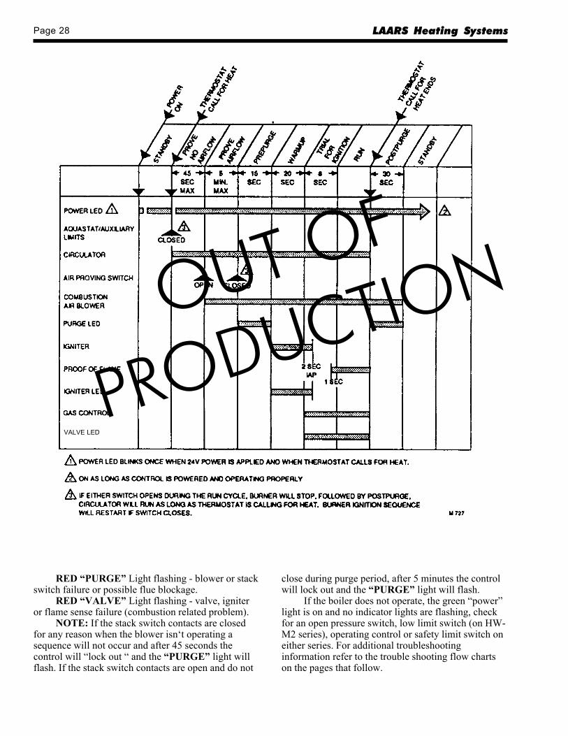
Page 28 LAARS Heating Systems
RED “PURGE” Light flashing - blower or stackswitch failure or possible flue blockage.
RED “VALVE” Light flashing - valve, igniteror flame sense failure (combustion related problem).
NOTE: If the stack switch contacts are closedfor any reason when the blower isn‘t operating asequence will not occur and after 45 seconds thecontrol will “lock out “ and the “PURGE” light willflash. If the stack switch contacts are open and do not
close during purge period, after 5 minutes the controlwill lock out and the “PURGE” light will flash.
If the boiler does not operate, the green “power”light is on and no indicator lights are flashing, checkfor an open pressure switch, low limit switch (on HW-M2 series), operating control or safety limit switch oneither series. For additional troubleshootinginformation refer to the trouble shooting flow chartson the pages that follow.
VALVE LED
OUT OF
PRODUCTION

H Series Page 29
PURGE - SEE FIGURE 26VALVE SEE FIGURE 28
1. LIMIT CIRCUIT OPENSEE FIGURE 25
2. NO CALL FOR HEAT/HOT WATER
REPLACE BOILERCONTROL2400-224
REPLACE TRANSFORMERAND RUN BOILERTHROUGH A FEW CYCLES
HAVE QUALIFIEDELECTRICIANREPAIR FAULT INWIRING TO THEBOILER
CHECK FOR VOLTAGE (24VAC) BETWEEN YELLOWWIRES AT BACK OF "VAC24 XFMR" CONNECTORON BOILER CONTROL
1. IS SERVICE SWITCH ON?2. IS CIRCUIT ON?3. ARE FUSES OR CIRCUIT
BREAKER OK?
CORRECT ANDRECYCLE BOILERTHROUGH A FEWCYCLES
CHECK FOR VOLTAGE(120 VAC) BETWEENBLACK AND WHITEWIRES AT BACK OF "120VAC" CONNECTOR ONBOILER CONTROL
DID BOILER RUN THROUGHA COMPLETE CYCLE ASDESCRIBED IN SEQUENCEOF EVENTS ON PAGE 25
PUMP OPERATES(120 V TO PUMP)
REFER TOFIGURE 30
YES NO
YES
NO
0 VOLTS
120VOLTS
0VOLTS
24VOLTS
* POOR SWITCH CONTACT ON RELAYS, ZONE VALVES, OR THERMOSTATS CAN CAUSE A FLASHING GREENLIGHT ON JOHNSON CONTROLS G856DBG - 5201.
AFTER 5 MINUTES ARE ANYRED LIGHTS FLASHING
YES NO
REFER TO FLOWCHART FOR SPECIFICPROBLEM
YES
GREEN LIGHT COMES ON
RESET BOILER CONTROL BY INTERRUPTINGPOWER AT SIDE OF UNIT FOR 15 SECONDS
NO
YES
NO
Figure 24. General Trouble Shooting.
OUT OF
PRODUCTION
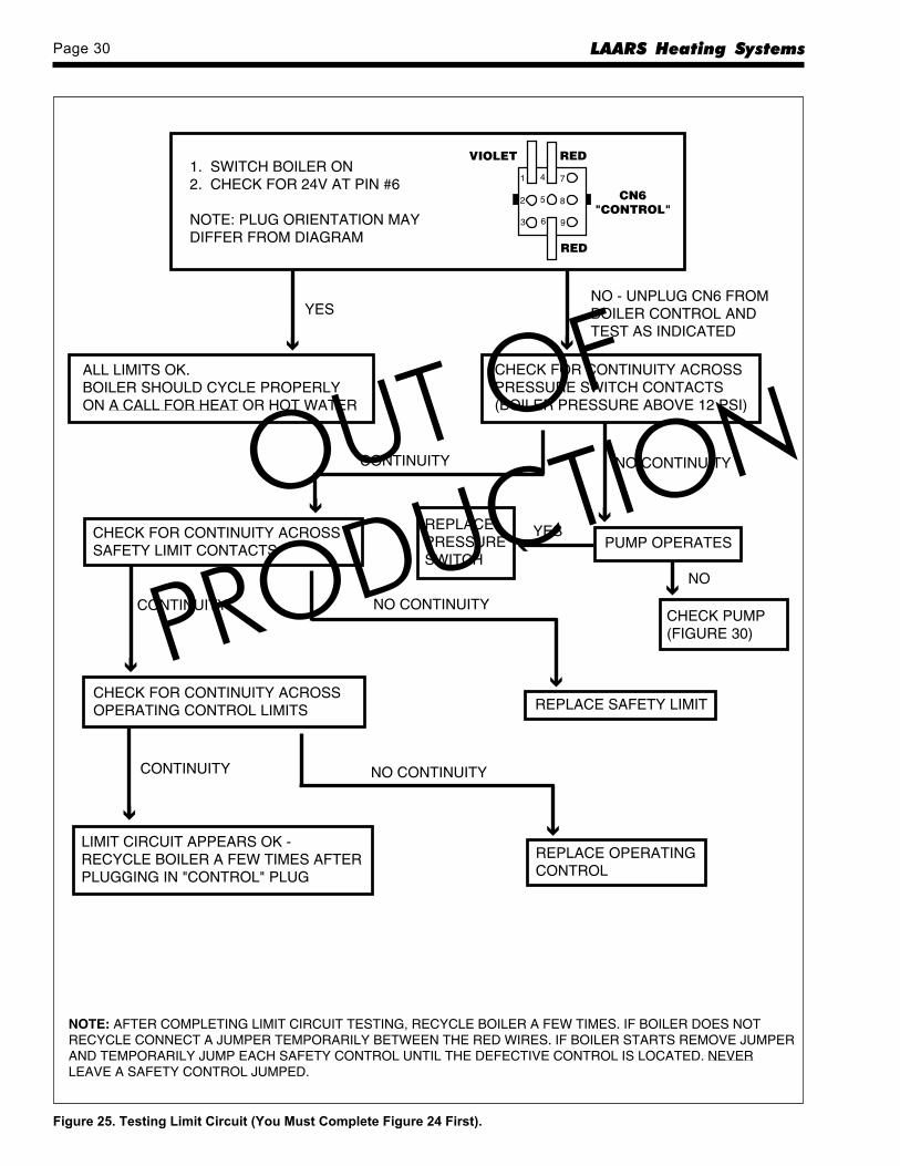
Page 30 LAARS Heating Systems
Figure 25. Testing Limit Circuit (You Must Complete Figure 24 First).
1
2
3
4
5
6
7
8
9
RED
RED
CN6
"CONTROL"
LIMIT CIRCUIT APPEARS OK -RECYCLE BOILER A FEW TIMES AFTERPLUGGING IN "CONTROL" PLUG
CHECK FOR CONTINUITY ACROSSOPERATING CONTROL LIMITS
CHECK FOR CONTINUITY ACROSSSAFETY LIMIT CONTACTS
REPLACE SAFETY LIMIT
REPLACE OPERATINGCONTROL
ALL LIMITS OK.BOILER SHOULD CYCLE PROPERLYON A CALL FOR HEAT OR HOT WATER
CHECK FOR CONTINUITY ACROSSPRESSURE SWITCH CONTACTS(BOILER PRESSURE ABOVE 12 PSI)
NOTE: AFTER COMPLETING LIMIT CIRCUIT TESTING, RECYCLE BOILER A FEW TIMES. IF BOILER DOES NOTRECYCLE CONNECT A JUMPER TEMPORARILY BETWEEN THE RED WIRES. IF BOILER STARTS REMOVE JUMPERAND TEMPORARILY JUMP EACH SAFETY CONTROL UNTIL THE DEFECTIVE CONTROL IS LOCATED. NEVERLEAVE A SAFETY CONTROL JUMPED.
CONTINUITY
CONTINUITY
CONTINUITY
NO CONTINUITY
NO CONTINUITY
VIOLET
YES
PUMP OPERATES
REPLACEPRESSURESWITCH
CHECK PUMP(FIGURE 30)
NO
NO CONTINUITY
YES
NO - UNPLUG CN6 FROMBOILER CONTROL ANDTEST AS INDICATED
1. SWITCH BOILER ON2. CHECK FOR 24V AT PIN #6
NOTE: PLUG ORIENTATION MAYDIFFER FROM DIAGRAM
OUT OF
PRODUCTION
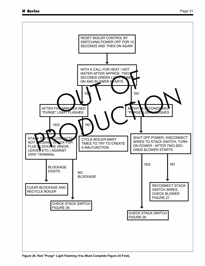
H Series Page 31
Figure 26. Red "Purge" Light Flashing (You Must Complete Figure 24 First).
RESET BOILER CONTROL BYSWITCHING POWER OFF FOR 15SECONDS AND THEN ON AGAIN
WITH A CALL FOR HEAT / HOTWATER AFTER APPROX. TWOSECONDS GREEN LIGHT COMESON AND BLOWER STARTS
AFTER 45 SECONDS RED"PURGE" LIGHT FLASHES
AFTER FIVE MINUTES RED"PURGE" LIGHT FLASHES
STACK SWITCH CONTACTSNOT CLOSING. CHECK FORFLUE BLOCKAGE (SNOW,LEAVES ETC.) AGAINSTVENT TERMINAL
CYCLE BOILER MANYTIMES TO TRY TO CREATEA MALFUNCTION
SHUT OFF POWER, DISCONNECTWIRES TO STACK SWITCH, TURNON POWER - AFTER TWO SEC-ONDS BLOWER STARTS
CLEAR BLOCKAGE ANDRECYCLE BOILER
RECONNECT STACKSWITCH WIRES.CHECK BLOWERFIGURE 27
CHECK STACK SWITCHFIGURE 28
YESBLOCKAGEEXISTS NO
BLOCKAGE
NO
NOYES
YES NO
CHECK STACK SWITCHFIGURE 28
OUT OF
PRODUCTION
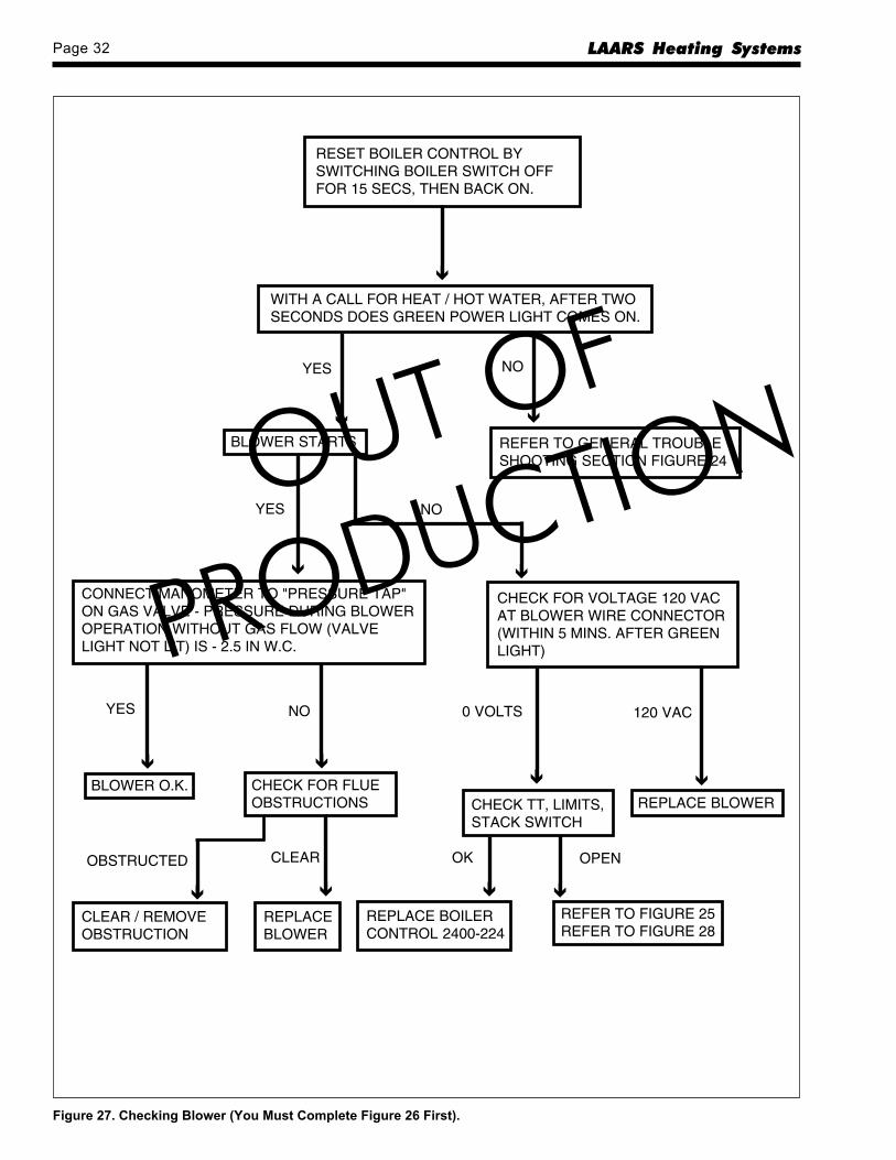
Page 32 LAARS Heating Systems
Figure 27. Checking Blower (You Must Complete Figure 26 First).
RESET BOILER CONTROL BYSWITCHING BOILER SWITCH OFFFOR 15 SECS, THEN BACK ON.
REFER TO GENERAL TROUBLESHOOTING SECTION FIGURE 24
CONNECT MANOMETER TO "PRESSURE TAP"ON GAS VALVE - PRESSURE DURING BLOWEROPERATION WITHOUT GAS FLOW (VALVELIGHT NOT LIT) IS - 2.5 IN W.C.
CHECK FOR VOLTAGE 120 VACAT BLOWER WIRE CONNECTOR(WITHIN 5 MINS. AFTER GREENLIGHT)
BLOWER O.K. CHECK FOR FLUEOBSTRUCTIONS
BLOWER STARTS
YES
YES NO
YES
NO
NO
REPLACE BLOWER
0 VOLTS 120 VAC
CHECK TT, LIMITS,STACK SWITCH
REPLACE BOILERCONTROL 2400-224
REFER TO FIGURE 25REFER TO FIGURE 28
OK OPEN
WITH A CALL FOR HEAT / HOT WATER, AFTER TWOSECONDS DOES GREEN POWER LIGHT COMES ON.
REPLACEBLOWER
CLEAR / REMOVEOBSTRUCTION
CLEAROBSTRUCTED
OUT OF
PRODUCTION

H Series Page 33
CLEAR
1. TURN OFF BOILER SWITCH2. REMOVE BOTH TUBES FROM
STACK SWITCH AND DISCONNECTELECTRICAL WIRES
3. CHECK FOR CONTINUITY ACROSSSWITCH TERMINALS
NOTE: CHECK TUBES ON STACK SWITCH FOR PROPER CONNECTIONS
1. ATTACH TUBES DISCONNECTEDFROM STACK SWITCH TO U-TUBEMANOMETER
2. TURN ON BOILER TO OPERATEBLOWER
3. MANOMETER INDICATES 1.5" W.C.OR GREATER
REPLACE STACKSWITCH P/N 2400-110
RECONNECT STACK SWITCHTUBES AND CHECK FORCONTINUITY BETWEENSTACK SWITCH TERMINALSWITH BLOWER OPERATING
CHECK FOR VENT OBSTRUCTIONS
CLEAR OBSTRUCTIONS &RECONNECT TUBES &ELECTRICAL WIRES TOSTACK SWITCH - STARTBOILER & RUN THROUGH AFEW CYCLES
CHECK BLOWERFIGURE 27
STACK SWITCH OK
REPLACE STACKSWITCH P/N 2400-110
CONTINUITY(0 OHMS)
NO CONTINUITY( OHMS)
CONTINUITY(0 OHMS)
OBSTRUCTED
NO
YES
NO CONTINUITY( OHMS)
Figure 28. Checking Stack Switch (You Must Complete Figure 27 First).
OUT OF
PRODUCTION
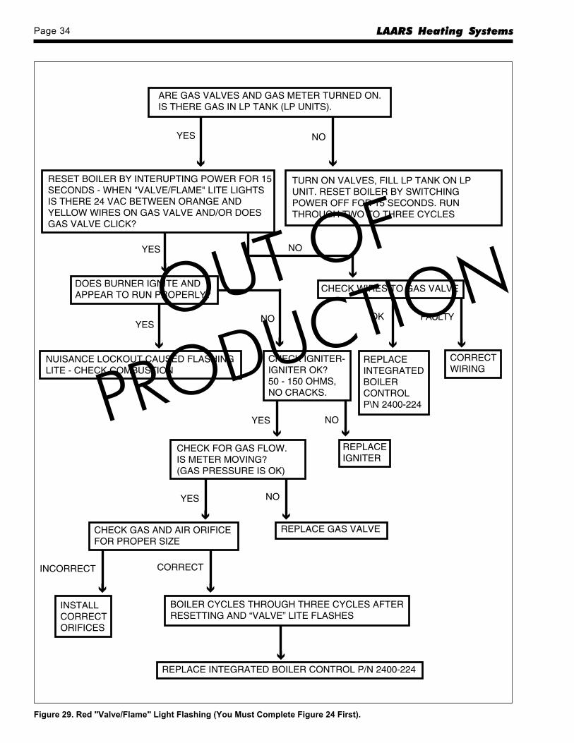
Page 34 LAARS Heating Systems
Figure 29. Red "Valve/Flame" Light Flashing (You Must Complete Figure 24 First).
RESET BOILER BY INTERUPTING POWER FOR 15SECONDS - WHEN "VALVE/FLAME" LITE LIGHTSIS THERE 24 VAC BETWEEN ORANGE ANDYELLOW WIRES ON GAS VALVE AND/OR DOESGAS VALVE CLICK?
TURN ON VALVES, FILL LP TANK ON LPUNIT. RESET BOILER BY SWITCHINGPOWER OFF FOR 15 SECONDS. RUNTHROUGH TWO TO THREE CYCLES
CHECK WIRES TO GAS VALVEDOES BURNER IGNITE ANDAPPEAR TO RUN PROPERLY?
NUISANCE LOCKOUT CAUSED FLASHINGLITE - CHECK COMBUSTION
CHECK IGNITER-IGNITER OK?50 - 150 OHMS,NO CRACKS.
REPLACEINTEGRATEDBOILERCONTROLP\N 2400-224
CORRECTWIRING
REPLACEIGNITER
REPLACE INTEGRATED BOILER CONTROL P/N 2400-224
INSTALLCORRECTORIFICES
BOILER CYCLES THROUGH THREE CYCLES AFTERRESETTING AND “VALVE” LITE FLASHES
CHECK GAS AND AIR ORIFICEFOR PROPER SIZE
REPLACE GAS VALVE
ARE GAS VALVES AND GAS METER TURNED ON.IS THERE GAS IN LP TANK (LP UNITS).
YES
YES
YES
NO
OK FAULTYNO
INCORRECT CORRECT
NO
CHECK FOR GAS FLOW.IS METER MOVING?(GAS PRESSURE IS OK)
YES NO
YES NO
OUT OF
PRODUCTION
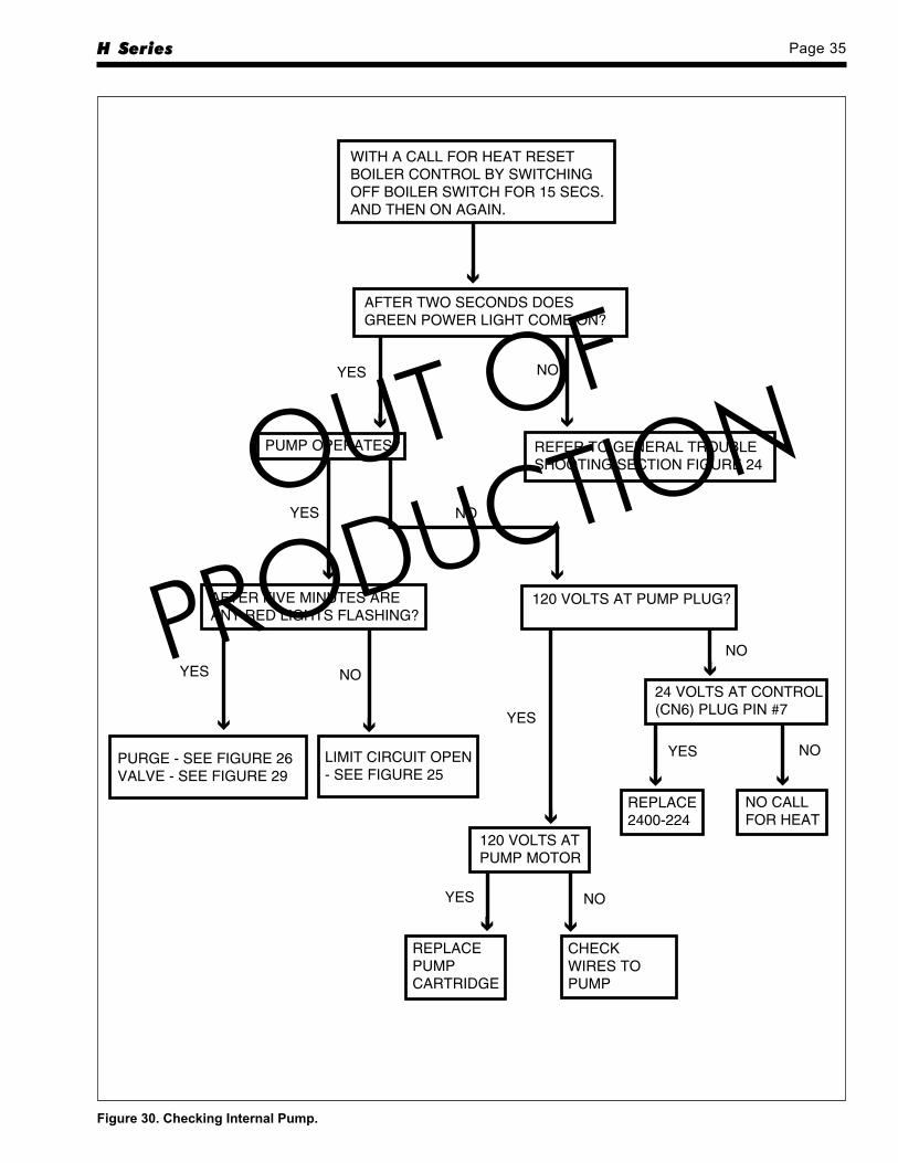
H Series Page 35
WITH A CALL FOR HEAT RESETBOILER CONTROL BY SWITCHINGOFF BOILER SWITCH FOR 15 SECS.AND THEN ON AGAIN.
AFTER TWO SECONDS DOESGREEN POWER LIGHT COME ON?
REFER TO GENERAL TROUBLESHOOTING SECTION FIGURE 24
PUMP OPERATES?
YES
YES NO
NO
AFTER FIVE MINUTES AREANY RED LIGHTS FLASHING?
120 VOLTS AT PUMP PLUG?
YES NO
LIMIT CIRCUIT OPEN- SEE FIGURE 25
PURGE - SEE FIGURE 26VALVE - SEE FIGURE 29
24 VOLTS AT CONTROL(CN6) PLUG PIN #7
NOYES
REPLACE2400-224
YES
120 VOLTS ATPUMP MOTOR
REPLACEPUMPCARTRIDGE
YES NO
CHECKWIRES TOPUMP
NO
NO CALLFOR HEAT
Figure 30. Checking Internal Pump.
OUT OF
PRODUCTION
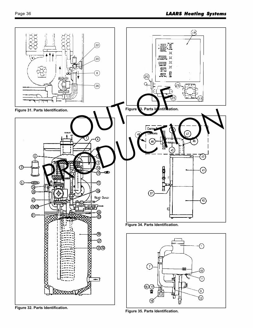
Page 36 LAARS Heating Systems
20
22
8
26
Figure 31. Parts Identification. Figure 33. Parts Identification.
Figure 32. Parts Identification.
Figure 34. Parts Identification.
Figure 35. Parts Identification.
OUT OF
PRODUCTION
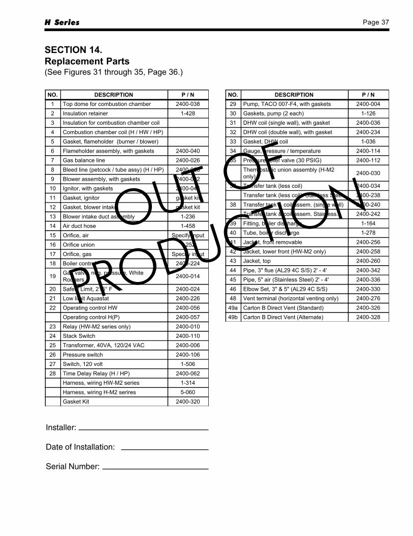
H Series Page 37
Installer:
Date of Installation:
Serial Number:
NO. DESCRIPTION P / N1 Top dome for combustion chamber 2400-0382 Insulation retainer 1-4283 Insulation for combustion chamber coil4 Combustion chamber coil (H / HW / HP)5 Gasket, flameholder (burner / blower)6 Flameholder assembly, with gaskets 2400-0407 Gas balance line 2400-0268 Bleed line (petcock / tube assy) (H / HP) 2400-0289 Blower assembly, with gaskets 2400-00210 Ignitor, with gaskets 2400-04611 Gasket, ignitor gasket kit12 Gasket, blower intake gasket kit13 Blower intake duct assembly 1-23614 Air duct hose 1-45815 Orifice, air Specify input16 Orifice union 1-25217 Orifice, gas Specify input18 Boiler control 2400-224
19 Gas valve, neg. pressure, WhiteRodgers 2400-014
20 Safety Limit, 215° F 2400-02421 Low limit Aquastat 2400-22622 Operating control HW 2400-056
Operating control H(P) 2400-05723 Relay (HW-M2 series only) 2400-01024 Stack Switch 2400-11025 Transformer, 40VA, 120/24 VAC 2400-00626 Pressure switch 2400-10627 Switch, 120 volt 1-50628 Time Delay Relay (H / HP) 2400-062
Harness, wiring HW-M2 series 1-314Harness, wiring H-M2 serires 5-060Gasket Kit 2400-320
NO. DESCRIPTION P / N29 Pump, TACO 007-F4, with gaskets 2400-00430 Gaskets, pump (2 each) 1-12631 DHW coil (single wall), with gasket 2400-03632 DHW coil (double wall), with gasket 2400-23433 Gasket, DHW coil 1-03634 Gauge, pressure / temperature 2400-11435 Pressure relief valve (30 PSIG) 2400-112
Thermostatic union assembly (H-M2only) 2400-030
37 Transfer tank (less coil) 2400-034Transfer tank (less coil). Stainless Steel 2400-238
38 Transfer tank & coil assem. (single wall) 2400-240Transfer tank & coil assem. Stainless. 2400-242
39 Fitting, boiler discharge 1-16440 Tube, boiler discharge 1-27841 Jacket, front removable 2400-25642 Jacket, lower front (HW-M2 only) 2400-25843 Jacket, top 2400-26044 Pipe, 3" flue (AL29 4C S/S) 2' - 4' 2400-34245 Pipe, 5" air (Stainless Steel) 2' - 4' 2400-33646 Elbow Set, 3" & 5" (AL29 4C S/S) 2400-33048 Vent terminal (horizontal venting only) 2400-276
49a Carton B Direct Vent (Standard) 2400-32649b Carton B Direct Vent (Alternate) 2400-328
SECTION 14.Replacement Parts(See Figures 31 through 35, Page 36.)
OUT OF
PRODUCTION
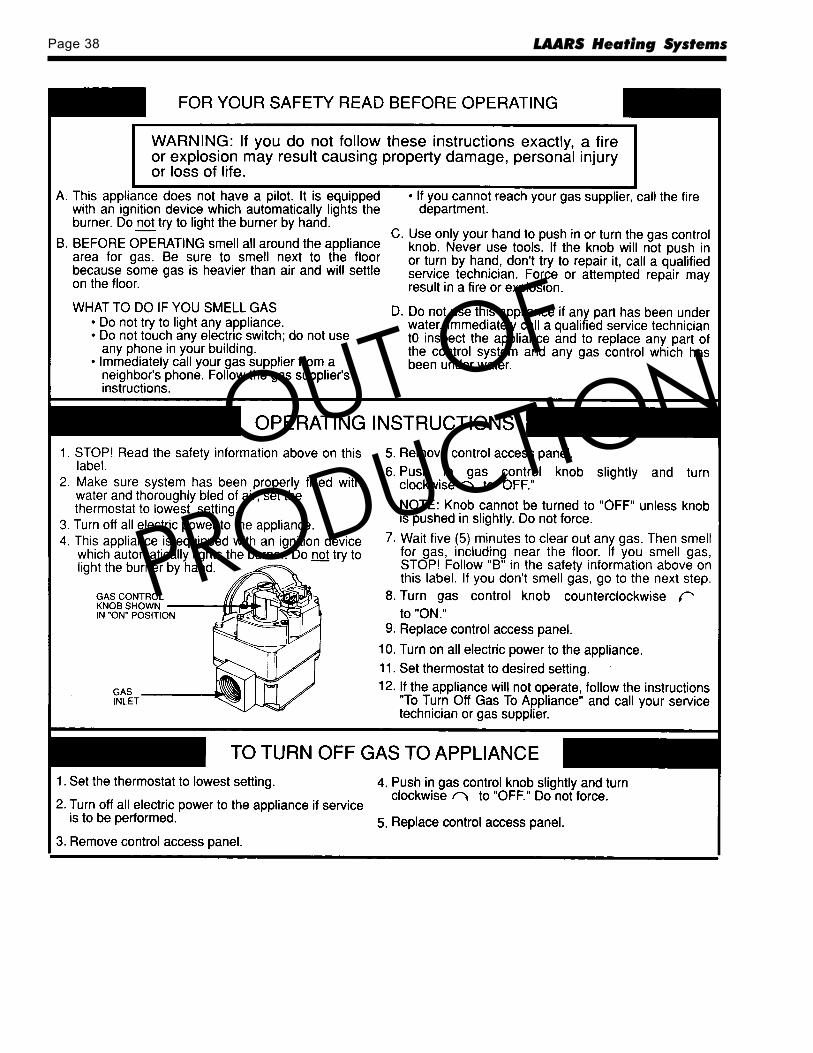
Page 38 LAARS Heating Systems
OUT OF
PRODUCTION
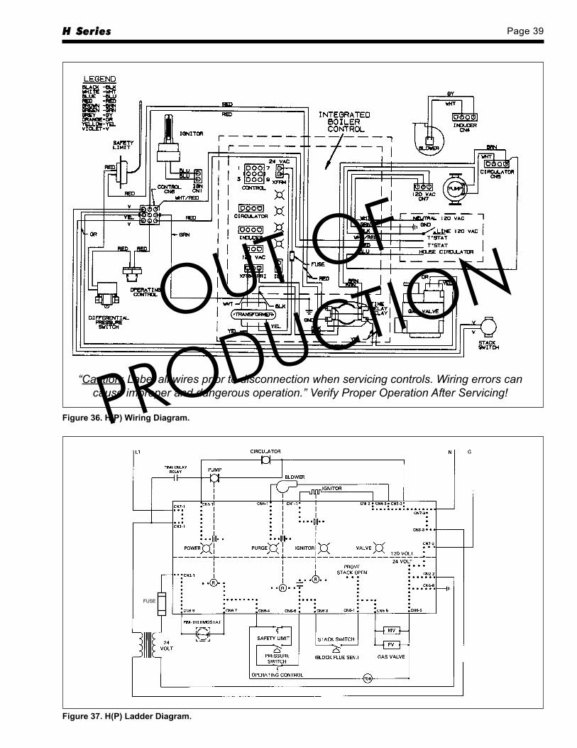
H Series Page 39
Figure 36. H(P) Wiring Diagram.
Figure 37. H(P) Ladder Diagram.
FUSE
“Caution: Label all wires prior to disconnection when servicing controls. Wiring errors cancause improper and dangerous operation.” Verify Proper Operation After Servicing!
OUT OF
PRODUCTION

Page 40 LAARS Heating Systems
Figure 38. HW Wiring Diagram.
Figure 39. HW Ladder Diagram.
FUSE
“Caution: Label all wires prior to disconnection when servicing controls. Wiring errors cancause improper and dangerous operation.” Verify Proper Operation After Servicing!
OUT OF
PRODUCTION
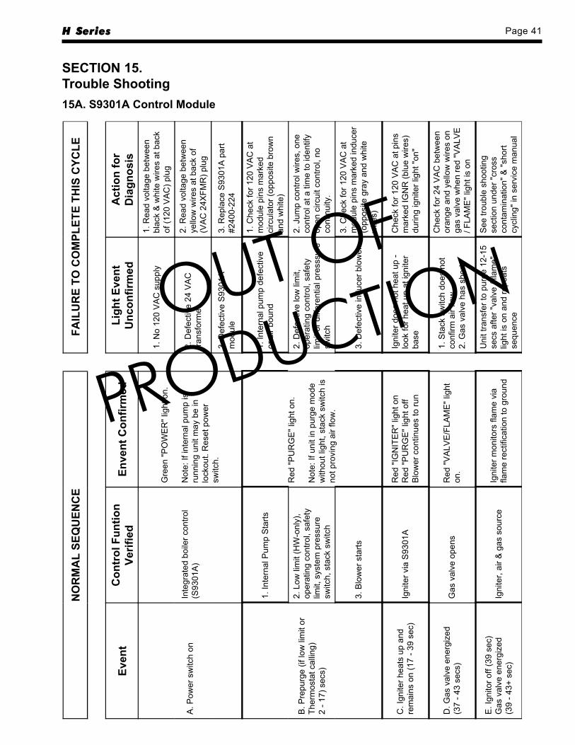
H Series Page 41
SECTION 15.Trouble Shooting15A. S9301A Control Module
NO
RM
AL
SEQ
UEN
CE
FAIL
UR
E TO
CO
MPL
ETE
THIS
CYC
LE
Even
tC
ontr
ol F
untio
nVe
rifie
dEn
vent
Con
firm
edLi
ght E
vent
Unc
onfir
med
Act
ion
for
Dia
gnos
is
A. P
ower
sw
itch
onIn
tegr
ated
boi
ler c
ontro
l(S
9301
A)
Gre
en "P
OW
ER
" lig
ht o
n.
Not
e: If
inte
rnal
pum
p is
runn
ing
unit
may
be
inlo
ckou
t. R
eset
pow
ersw
itch.
1. N
o 12
0 V
AC
sup
ply
1. R
ead
volta
ge b
etw
een
blac
k &
whi
te w
ires
at b
ack
of (1
20 V
AC
) plu
g
2. D
efec
tive
24 V
AC
trans
form
er
2. R
ead
volta
ge b
etw
een
yello
w w
ires
at b
ack
of(V
AC
24X
FMR
) plu
g
3. D
efec
tive
S93
01A
mod
ule
3. R
epla
ce S
9301
A p
art
#240
0-22
4
B. P
repu
rge
(if lo
w li
mit
orTh
erm
osta
t cal
ling)
2 - 1
7) s
ecs)
1. In
tern
al P
ump
Sta
rts
Red
"PU
RG
E" l
ight
on.
Not
e: If
uni
t in
purg
e m
ode
with
out l
ight
, sta
ck s
witc
h is
not p
rovi
ng a
ir flo
w.
1. In
tern
al p
ump
defe
ctiv
eor
air
boun
d
1. C
heck
for 1
20 V
AC
at
mod
ule
pins
mar
ked
circ
ulat
or (o
ppos
ite b
row
nan
d w
hite
)
2. L
ow li
mit
(HW
-onl
y),
oper
atin
g co
ntro
l, sa
fety
limit,
sys
tem
pre
ssur
esw
itch,
sta
ck s
witc
h
2. D
efec
tive
low
lim
it,op
erat
ing
cont
rol,
safe
tylim
it or
diff
eren
tial p
ress
sure
switc
h
2. J
ump
cont
rol w
ires,
one
cont
rol a
t a ti
me
to id
entif
yop
en c
ircui
t con
trol,
noco
ntin
uity
.
3. B
low
er s
tarts
3. D
efec
tive
indu
cer b
low
er
3. C
heck
for 1
20 V
AC
at
mod
ule
pins
mar
ked
indu
cer
(opp
osite
gra
y an
d w
hite
wire
s)
C. I
gnite
r hea
ts u
p an
dre
mai
ns o
n (1
7 - 3
9 se
c)Ig
nite
r via
S93
01A
Red
"IG
NIT
ER
" lig
ht o
nR
ed "P
UR
GE
" lig
ht o
ffB
low
er c
ontin
ues
to ru
n
Igni
ter d
oes
not h
eat u
p -
look
for h
eat u
p at
igni
ter
base
Che
ck fo
r 120
VA
C a
t pin
sm
arke
d IG
NR
(blu
e w
ires)
durin
g ig
nite
r lig
ht "o
n"
D. G
as v
alve
ene
rgiz
ed(3
7 - 4
3 se
cs)
Gas
val
ve o
pens
Red
"VA
LVE
/FLA
ME
" lig
hton
.
1. S
tack
sw
itch
does
not
conf
irm a
ir flo
w.
2. G
as v
alve
has
sho
rt.
Che
ck fo
r 24
VA
C b
etw
een
oran
ge a
nd y
ello
w w
ires
onga
s va
lve
whe
n re
d "V
ALV
E/ F
LAM
E" l
ight
is o
n
E. I
gnito
r off
(39
sec)
Gas
val
ve e
nerg
ized
(39
- 43+
sec
)Ig
nite
r, ai
r & g
as s
ourc
eIg
nite
r mon
itors
flam
e vi
afla
me
rect
ifica
tion
to g
roun
d
Uni
t tra
nsfe
r to
purg
e 12
-15
secs
afte
r "va
lve
/ fla
me"
light
is o
n an
d re
peat
sse
quen
ce
See
trou
ble
shoo
ting
sect
ion
unde
r "cr
oss
cont
amin
atio
n" &
"sho
rtcy
clin
g" in
ser
vice
man
ual
OUT OF
PRODUCTION
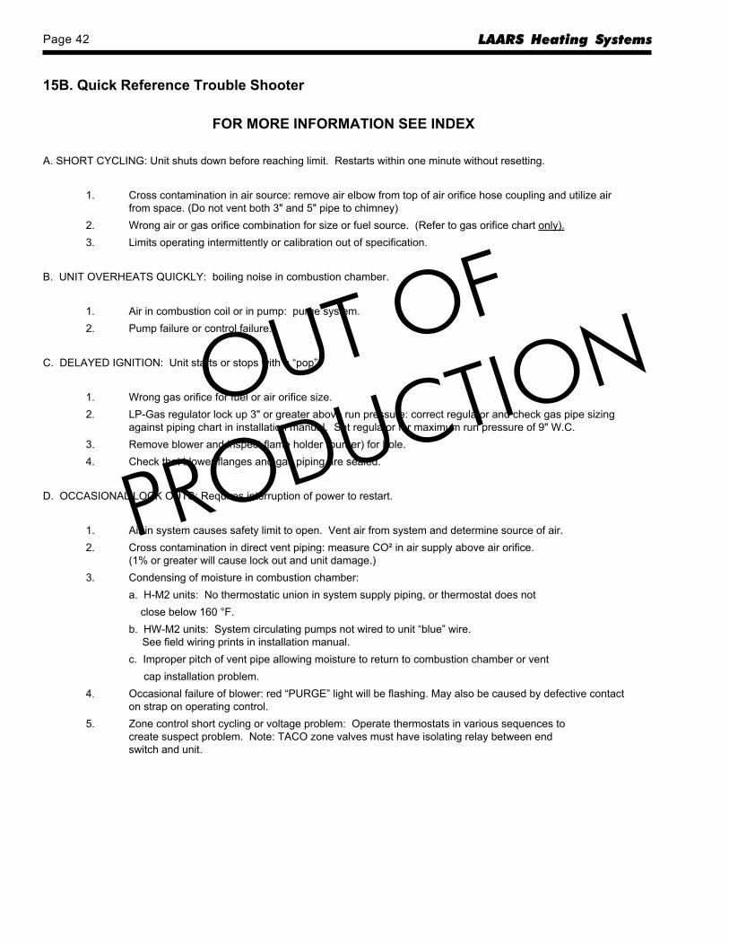
Page 42 LAARS Heating Systems
15B. Quick Reference Trouble Shooter
FOR MORE INFORMATION SEE INDEX
A. SHORT CYCLING: Unit shuts down before reaching limit. Restarts within one minute without resetting.
1. Cross contamination in air source: remove air elbow from top of air orifice hose coupling and utilize airfrom space. (Do not vent both 3" and 5" pipe to chimney)
2. Wrong air or gas orifice combination for size or fuel source. (Refer to gas orifice chart only).3. Limits operating intermittently or calibration out of specification.
B. UNIT OVERHEATS QUICKLY: boiling noise in combustion chamber.
1. Air in combustion coil or in pump: purge system.2. Pump failure or control failure.
C. DELAYED IGNITION: Unit starts or stops with a “pop”.
1. Wrong gas orifice for fuel or air orifice size.2. LP-Gas regulator lock up 3" or greater above run pressure: correct regulator and check gas pipe sizing
against piping chart in installation manual. Set regulator for maximum run pressure of 9" W.C.3. Remove blower and inspect flame holder (burner) for hole.4. Check that blower flanges and gas piping are sealed.
D. OCCASIONAL LOCK OUTS: Requires interruption of power to restart.
1. Air in system causes safety limit to open. Vent air from system and determine source of air.2. Cross contamination in direct vent piping: measure CO² in air supply above air orifice.
(1% or greater will cause lock out and unit damage.)3. Condensing of moisture in combustion chamber:
a. H-M2 units: No thermostatic union in system supply piping, or thermostat does not close below 160 °F.b. HW-M2 units: System circulating pumps not wired to unit “blue” wire.
See field wiring prints in installation manual.c. Improper pitch of vent pipe allowing moisture to return to combustion chamber or vent cap installation problem.
4. Occasional failure of blower: red “PURGE” light will be flashing. May also be caused by defective contacton strap on operating control.
5. Zone control short cycling or voltage problem: Operate thermostats in various sequences tocreate suspect problem. Note: TACO zone valves must have isolating relay between endswitch and unit.
OUT OF
PRODUCTION

H Series Page 43
OUT OF
PRODUCTION
1-51
0
Laars WarrantyH Series
Residential Hydronic Heating and Domestic Hot Water ApplianceThis Laars product is backed by this
limited twenty year warranty to assure your complete satisfaction.
Laars warrants each boiler to be free from defects in material and workmanship according to the following terms, conditions and timeperiods:COVERAGE:A. First Year Warranty includes repair replacement for a period of one year after original installation of all parts found to be
defectively manufactured.B. Second through Twentieth Year Warranty includes: repair or replacement of the following parts for the second through
twentieth year after original installation of boiler, heat exchanger or coil, storage tank; or domestic hot water heat exchangerfound to be defectively manufactured, at a cost to the consumer equal to the percentage indicated below of the manufacturersthen list price for replacement parts.Year of Claim 2 thru 5 6 & 7 8&9 10 & 11 12 & 13 14 & 15 16 & 17 18 & 19 20Percentage Paidby Consumer 0% 50% 55% 60% 65% 70% 75% 80% 90%
C. In the absence of suitable proof of installation date (Bill of Sale or warranty card registration), the specified warranty period willcommence 30 days after the date of manufacture.
D. This warranty extends only to boilers in residential applications which have been properly installed, operated and maintained.This warranty is nontransferable and applies to the original owners at the original installation location. Laars makes no expresswarranties other than the warranties contained herein.
EXCLUSIONS:A. First Year Warranty Excludes:
1. All labor charges incurred by any person in connection with the examination, replacement and/or repair of partsclaimed to be defective.
2. Malfunction of parts due to improper application installation or operation.3. Failures resulting form abuse, accident, negligence, freezing or acts of God.4. Damage caused by hard water, scale buildup, excessive oxygenation or external leakage.
B. Second through Twentieth Year excludes: All of above "Part A" plus: Sheet metal jacket, insulation, electrical and mechanicalcomponents furnished to Laars by other manufacturers, such as pumps, relays, controls, gauges, etc. Such components may carrywarranties from their respective manufacturers and Laars has requested its dealers to assist consumers in obtaining performanceof any warranties which may cover such components.
C. Laars requires all alleged defective part(s) be returned through trade channels and replacement part(s) will, if warranty conditionsare met, be provided by Laars through the wholesaler. In this case, the cost of shipment to Laars is borne by the consumer.
PROCEDURE FOR WARRANTY SERVICEFor Warranty service, contact your installing contractor with the following information: Boiler model number, serial number (located on theboiler rating plate) and the date of installation. The installing contractor will notify the wholesaler from whom the boiler was purchased. Allalleged defective part(s) must be returned through trade channels and replacement part(s) will if warranty conditions are met, be providedby Laars through the wholesaler. If there are any questions about the coverage of this warranty, please contact Laars at the addressshown below.
LEGAL RIGHTSNo other party is authorized to make any other warranties on Laars' behalf. No other warranty expressed implied, including warranty ofmerchantability or fitness for a particular purpose is made, This warranty does not extend to liability for incidentals, special or consequentialdamages.Some states and provinces do not allow limitations on how long as implied warranty lasts or the exclusion or limitation of incidental orconsequential damages, so the above limitation or exclusions may not apply to you. This warranty gives you specific legal rights, andyou may also have other rights which vary from state to state and by province.
20 Industrial Way, Rochester, NH 03867 • 603.335.6300 • Fax 603.335.33551355 Kuehner Drive, Simi Valley, CA 93063 • 800.900.9276 • Fax 800.559.1583 (Sales, Service)480 S. Service Rd. West, Oakville, Ontario, Canada L6K 2H4 • 905.844.8233 • Fax 905.844.2635www.Laars.com Litho in U.S.A. © Laars Heating Systems 9904 Document 1105
OUT OF
PRODUCTION