GV-Mobile Server - CCTV Camera Pros · PDF fileTo install GV-Mobile Server, select Install...
37
User's Manual V1.3 GV-Mobile Server MBSV13-A
Transcript of GV-Mobile Server - CCTV Camera Pros · PDF fileTo install GV-Mobile Server, select Install...
User's Manual V1.3
GV-Mobile Server
MBSV13-A
© 2012 GeoVision, Inc. All rights reserved. Under the copyright laws, this manual may not be copied, in whole or in part, without the written consent of GeoVision. Every effort has been made to ensure that the information in this manual is accurate. GeoVision, Inc. makes no expressed or implied warranty of any kind and assumes no responsibility for errors or omissions. No liability is assumed for incidental or consequential damages arising from the use of the information or products contained herein. Features and specifications are subject to change without notice. GeoVision, Inc. 9F, No. 246, Sec. 1, Neihu Rd., Neihu District, Taipei, Taiwan Tel: +886-2-8797-8377 Fax: +886-2-8797-8335 http://www.geovision.com.tw Trademarks used in this manual: GeoVision, the GeoVision logo and GV series products are trademarks of GeoVision, Inc. Windows and Windows XP are registered trademarks of Microsoft Corporation. May 2012
i
Content
Chapter 1 Introduction .......................................................................................... 1 1.1 Packing List .............................................................................................................................5 1.2 Minimum System Requirement...............................................................................................5 1.3 Options....................................................................................................................................6 1.4 Compatible Firmware ..............................................................................................................6
Chapter 2 Installation ............................................................................................ 7 2.1 Installing the GV-Mobile Server...............................................................................................7 2.2 Starting the GV-Mobile Server ................................................................................................8
Chapter 3 Establishing Connections ................................................................. 10 3.1 Connecting to GV-System.....................................................................................................10 3.2 Connecting to GV-Recording Server / GV-Video Gateway................................................... 11 3.3 Connecting to IP Devices Directly.........................................................................................13
Chapter 4 Configuring the Channel ................................................................... 15 4.1 Setting the Individual Channel ..............................................................................................15 4.2 Setting the Matrix Channel....................................................................................................17
Chapter 5 Accessing the Live View.................................................................... 19 5.1 Using GV-IP Decoder Box / GV-Pad.....................................................................................19 5.2 Using iPhone / iPod Touch / iPad..........................................................................................22 5.3 Using Android Smartphone / Tablet ......................................................................................25 5.4 Using Third-Party Surveillance Software ..............................................................................27 5.5 Using Non-IE Browsers.........................................................................................................29
Chapter 6 Setting Up the Router ........................................................................ 30 6.1 Registering a Domain Name for the Router..........................................................................31 6.2 Opening Ports on the Router ................................................................................................32
Specifications......................................................................................................... 34
1
Chapter 1 Introduction GV-Mobile Server is an application that can encode up to 32 video channels and subsequently allows for live view access from GV-IP Decoder Box, GV-Pad, and mobile devices including Android Smartphone, iPad, iPhone, and iPod Touch. Third-party surveillance software can also access video channels from GV-Mobile Server through RTSP. The advantages of GV-Mobile Server include:
• Live view access of analog camera (connected to GV-System)
• Live view access of up to 4 user-selectable matrix channels
• Provides for dual streams
• Significantly reduces CPU loading and bandwidth usage of IP video devices
• User-configurable frame rate, quality, codec type and resolution for each camera stream
• Remote access to live view using non-IE browsers
Through GV-Mobile Server, the clients can:
• access GeoVision and third-party cameras connected to the GV-System.
• access GeoVision and third-party IP channels connected to GV-Video Gateway / GV-Recording Server
• directly access GeoVision and third-party devices
Introduction
2
1
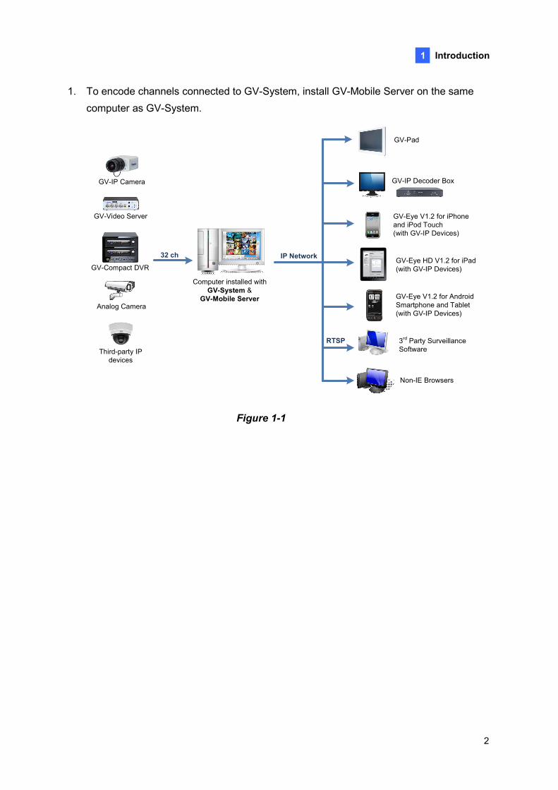
1. To encode channels connected to GV-System, install GV-Mobile Server on the same computer as GV-System.
Computer installed with GV-System &
GV-Mobile Server
32 ch
GV-IP Decoder Box
3rd Party Surveillance Software
GV-Pad
GV-Eye V1.2 for Android Smartphone and Tablet (with GV-IP Devices)
GV-Eye HD V1.2 for iPad (with GV-IP Devices)
RTSP
GV-Eye V1.2 for iPhone and iPod Touch(with GV-IP Devices)
IP NetworkGV-Compact DVR
GV-Video Server
Analog Camera
GV-IP Camera
Third-party IP devices
Non-IE Browsers
Figure 1-1
3
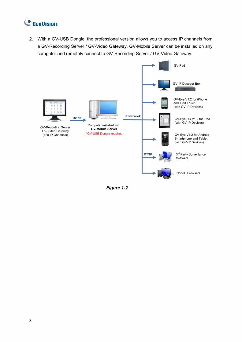
2. With a GV-USB Dongle, the professional version allows you to access IP channels from a GV-Recording Server / GV-Video Gateway. GV-Mobile Server can be installed on any computer and remotely connect to GV-Recording Server / GV-Video Gateway.
Computer installed withGV-Mobile Server
32 ch
GV-Recording Server GV-Video Gateway(128 IP Channels) *GV-USB Dongle required
GV-IP Decoder Box
3rd Party Surveillance Software
GV-Pad
GV-Eye V1.2 for Android Smartphone and Tablet (with GV-IP Devices)
GV-Eye HD V1.2 for iPad (with GV-IP Devices)
RTSP
GV-Eye V1.2 for iPhone and iPod Touch(with GV-IP Devices)
IP Network
Non-IE Browsers
Figure 1-2
Introduction
4
1
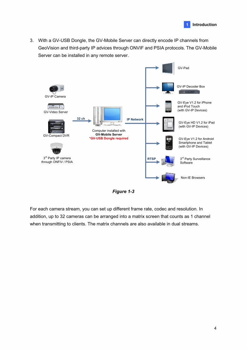
3. With a GV-USB Dongle, the GV-Mobile Server can directly encode IP channels from GeoVision and third-party IP advices through ONVIF and PSIA protocols. The GV-Mobile Server can be installed in any remote server.
32 ch
Computer installed with GV-Mobile Server
*GV-USB Dongle required
GV-Video Server
GV-Compact DVR
3rd Party IP camera through ONFIV / PSIA
GV-IP Camera
GV-IP Decoder Box
3rd Party Surveillance Software
GV-Pad
GV-Eye V1.2 for Android Smartphone and Tablet (with GV-IP Devices)
GV-Eye HD V1.2 for iPad (with GV-IP Devices)
RTSP
GV-Eye V1.2 for iPhone and iPod Touch(with GV-IP Devices)
IP Network
Non-IE Browsers
Figure 1-3
For each camera stream, you can set up different frame rate, codec and resolution. In addition, up to 32 cameras can be arranged into a matrix screen that counts as 1 channel when transmitting to clients. The matrix channels are also available in dual streams.
5
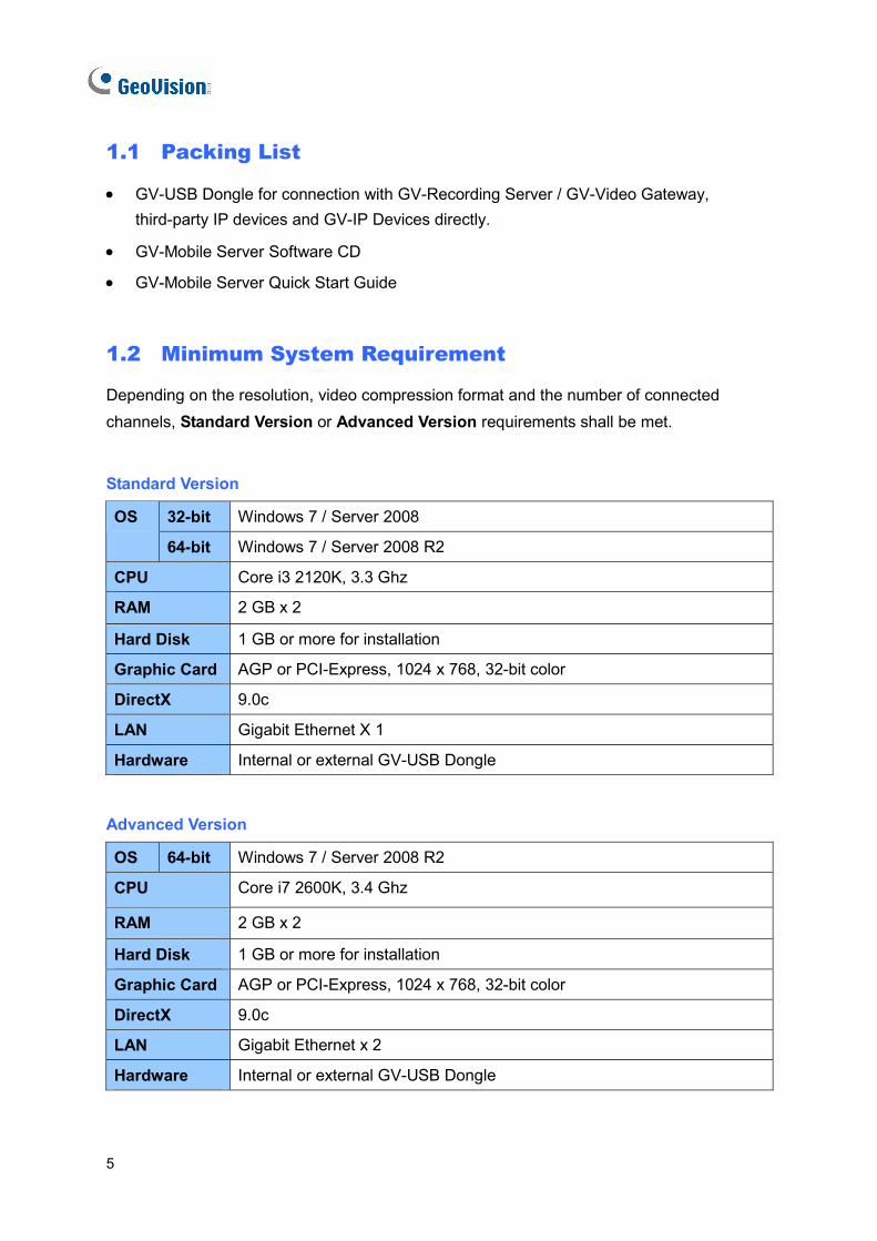
1.1 Packing List
• GV-USB Dongle for connection with GV-Recording Server / GV-Video Gateway, third-party IP devices and GV-IP Devices directly.
• GV-Mobile Server Software CD
• GV-Mobile Server Quick Start Guide
1.2 Minimum System Requirement
Depending on the resolution, video compression format and the number of connected channels, Standard Version or Advanced Version requirements shall be met.
Standard Version
32-bit Windows 7 / Server 2008 OS
64-bit Windows 7 / Server 2008 R2
CPU Core i3 2120K, 3.3 Ghz
RAM 2 GB x 2
Hard Disk 1 GB or more for installation
Graphic Card AGP or PCI-Express, 1024 x 768, 32-bit color
DirectX 9.0c
LAN Gigabit Ethernet X 1
Hardware Internal or external GV-USB Dongle
Advanced Version
OS 64-bit Windows 7 / Server 2008 R2
CPU Core i7 2600K, 3.4 Ghz
RAM 2 GB x 2
Hard Disk 1 GB or more for installation
Graphic Card AGP or PCI-Express, 1024 x 768, 32-bit color
DirectX 9.0c
LAN Gigabit Ethernet x 2
Hardware Internal or external GV-USB Dongle
Introduction
6
1
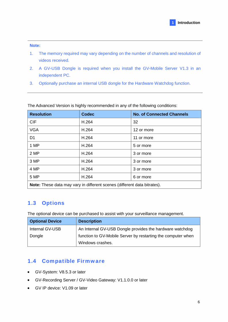
Note:
1. The memory required may vary depending on the number of channels and resolution of videos received.
2. A GV-USB Dongle is required when you install the GV-Mobile Server V1.3 in an independent PC.
3. Optionally purchase an internal USB dongle for the Hardware Watchdog function.
The Advanced Version is highly recommended in any of the following conditions:
Resolution Codec No. of Connected Channels
CIF H.264 32
VGA H.264 12 or more
D1 H.264 11 or more
1 MP H.264 5 or more
2 MP H.264 3 or more
3 MP H.264 3 or more
4 MP H.264 3 or more
5 MP H.264 6 or more
Note: These data may vary in different scenes (different data bitrates).
1.3 Options
The optional device can be purchased to assist with your surveillance management.
Optional Device Description
Internal GV-USB Dongle
An Internal GV-USB Dongle provides the hardware watchdog function to GV-Mobile Server by restarting the computer when Windows crashes.
1.4 Compatible Firmware
• GV-System: V8.5.3 or later
• GV-Recording Server / GV-Video Gateway: V1.1.0.0 or later
• GV IP device: V1.09 or later
7
Chapter 2 Installation
2.1 Installing the GV-Mobile Server
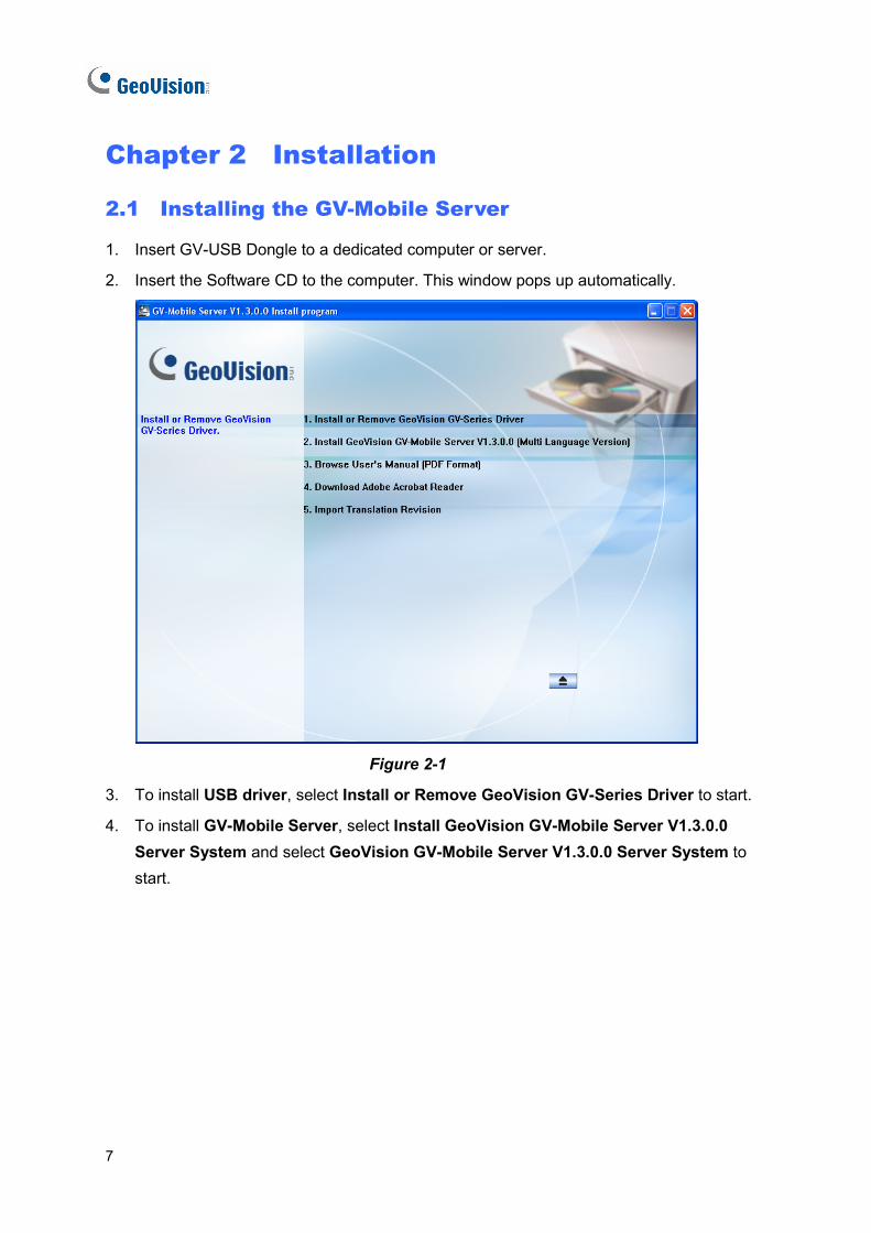
1. Insert GV-USB Dongle to a dedicated computer or server.
2. Insert the Software CD to the computer. This window pops up automatically.
Figure 2-1
3. To install USB driver, select Install or Remove GeoVision GV-Series Driver to start.
4. To install GV-Mobile Server, select Install GeoVision GV-Mobile Server V1.3.0.0 Server System and select GeoVision GV-Mobile Server V1.3.0.0 Server System to start.
Installation
8
2
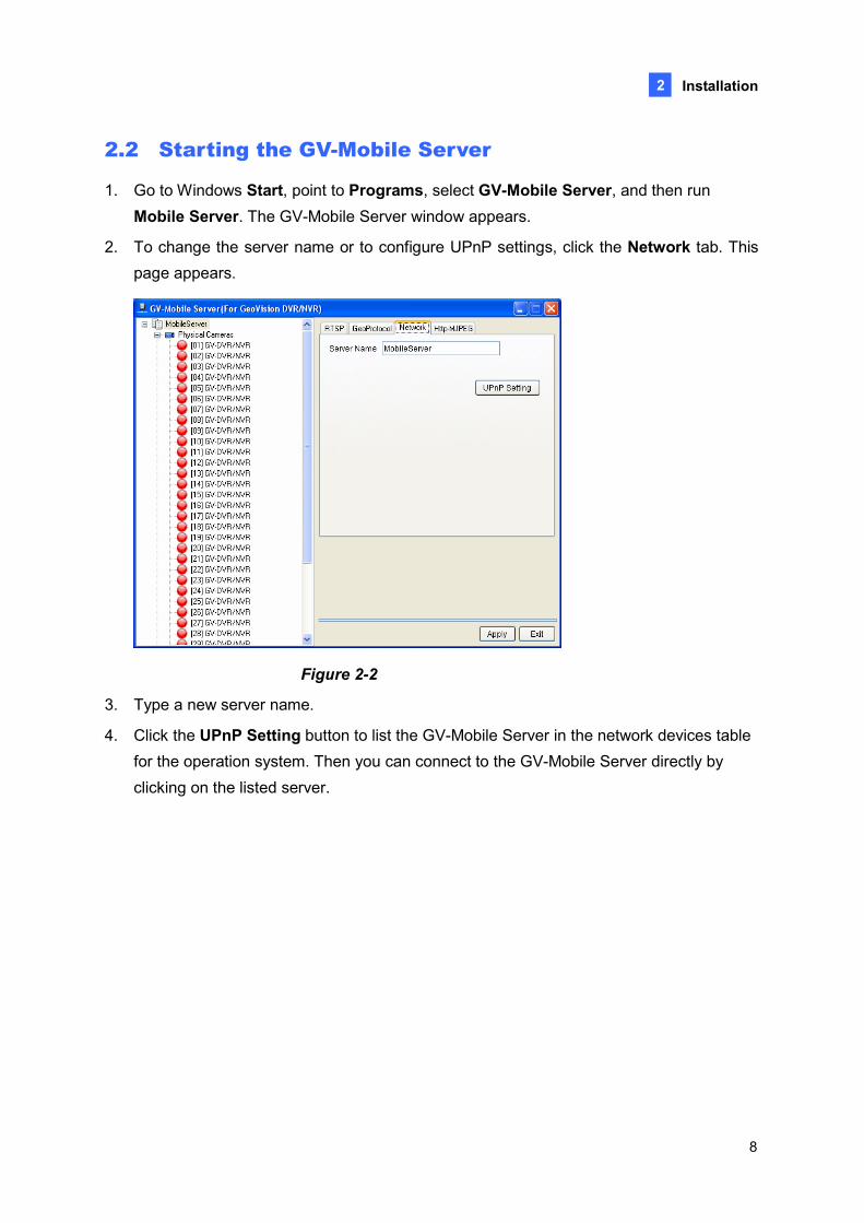
2.2 Starting the GV-Mobile Server
1. Go to Windows Start, point to Programs, select GV-Mobile Server, and then run Mobile Server. The GV-Mobile Server window appears.
2. To change the server name or to configure UPnP settings, click the Network tab. This page appears.
Figure 2-2
3. Type a new server name.
4. Click the UPnP Setting button to list the GV-Mobile Server in the network devices table for the operation system. Then you can connect to the GV-Mobile Server directly by clicking on the listed server.
9
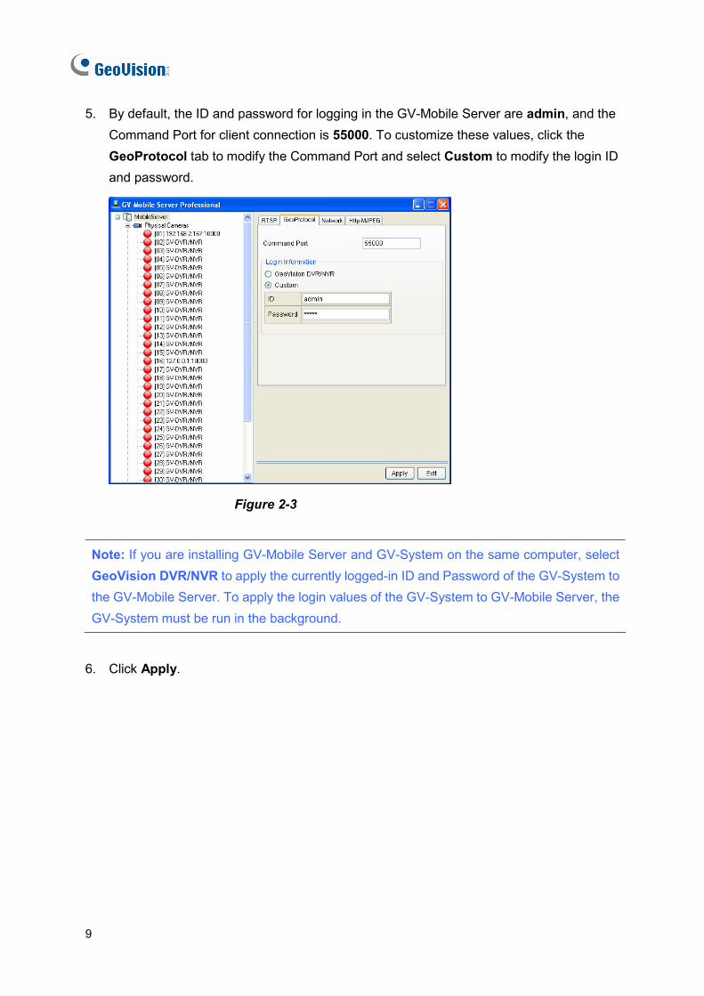
5. By default, the ID and password for logging in the GV-Mobile Server are admin, and the Command Port for client connection is 55000. To customize these values, click the GeoProtocol tab to modify the Command Port and select Custom to modify the login ID and password.
Figure 2-3
Note: If you are installing GV-Mobile Server and GV-System on the same computer, select GeoVision DVR/NVR to apply the currently logged-in ID and Password of the GV-System to the GV-Mobile Server. To apply the login values of the GV-System to GV-Mobile Server, the GV-System must be run in the background.
6. Click Apply.
Establishing Connections
10
3
Chapter 3 Establishing Connections
3.1 Connecting to GV-System
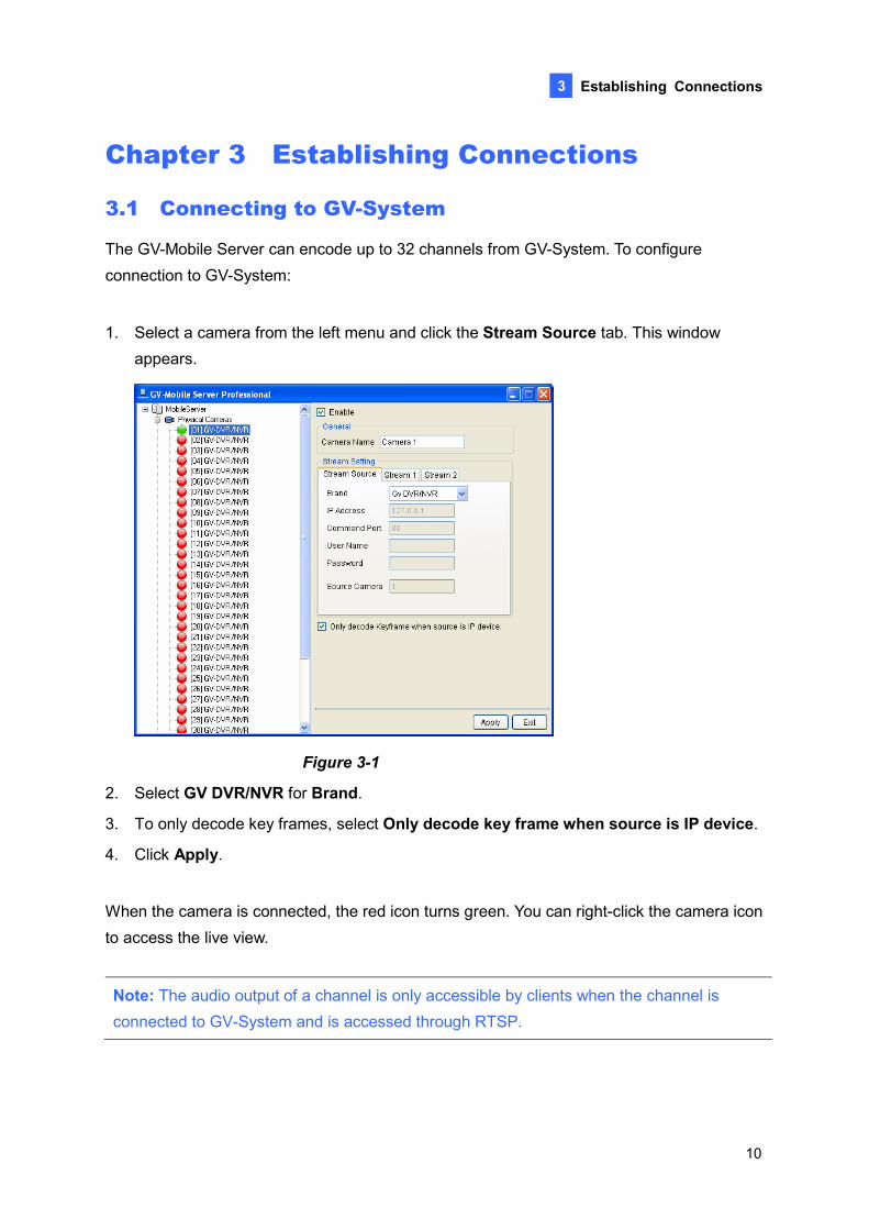
The GV-Mobile Server can encode up to 32 channels from GV-System. To configure connection to GV-System:
1. Select a camera from the left menu and click the Stream Source tab. This window appears.
Figure 3-1
2. Select GV DVR/NVR for Brand.
3. To only decode key frames, select Only decode key frame when source is IP device.
4. Click Apply.
When the camera is connected, the red icon turns green. You can right-click the camera icon to access the live view.
Note: The audio output of a channel is only accessible by clients when the channel is connected to GV-System and is accessed through RTSP.
11
3.2 Connecting to GV-Recording Server / GV-Video Gateway
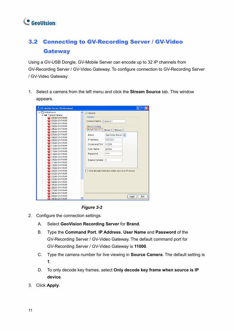
Using a GV-USB Dongle, GV-Mobile Server can encode up to 32 IP channels from GV-Recording Server / GV-Video Gateway. To configure connection to GV-Recording Server / GV-Video Gateway:
1. Select a camera from the left menu and click the Stream Source tab. This window appears.
Figure 3-2
2. Configure the connection settings.
A. Select GeoVision Recording Server for Brand.
B. Type the Command Port, IP Address, User Name and Password of the GV-Recording Server / GV-Video Gateway. The default command port for GV-Recording Server / GV-Video Gateway is 11000.
C. Type the camera number for live viewing in Source Camera. The default setting is 1.
D. To only decode key frames, select Only decode key frame when source is IP device.
3. Click Apply.
Establishing Connections
12
3
When the camera is connected, the red icon turns green. You can right-click the camera icon to access the live view.
Note: The TCP/IP Connection port (active connection port) on the GV-Recording Server / GV-Video Gateway must match the Command port setting (default 11000) here.
13
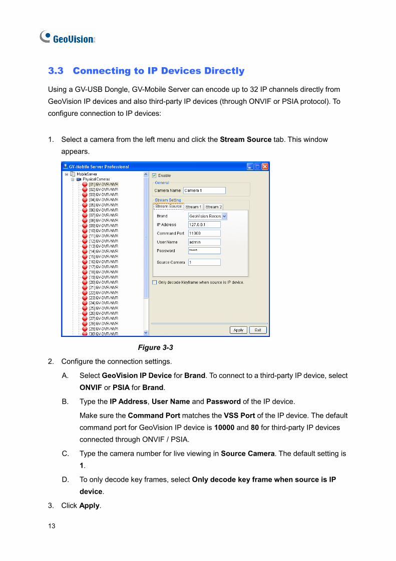
3.3 Connecting to IP Devices Directly
Using a GV-USB Dongle, GV-Mobile Server can encode up to 32 IP channels directly from GeoVision IP devices and also third-party IP devices (through ONVIF or PSIA protocol). To configure connection to IP devices:
1. Select a camera from the left menu and click the Stream Source tab. This window appears.
Figure 3-3
2. Configure the connection settings.
A. Select GeoVision IP Device for Brand. To connect to a third-party IP device, select ONVIF or PSIA for Brand.
B. Type the IP Address, User Name and Password of the IP device.
Make sure the Command Port matches the VSS Port of the IP device. The default command port for GeoVision IP device is 10000 and 80 for third-party IP devices connected through ONVIF / PSIA.
C. Type the camera number for live viewing in Source Camera. The default setting is 1.
D. To only decode key frames, select Only decode key frame when source is IP device.
3. Click Apply.
Establishing Connections
14
3
When the camera is connected, the red icon turns green. You can right-click the camera icon to access the live view.
15
Chapter 4 Configuring the Channel
4.1 Setting the Individual Channel
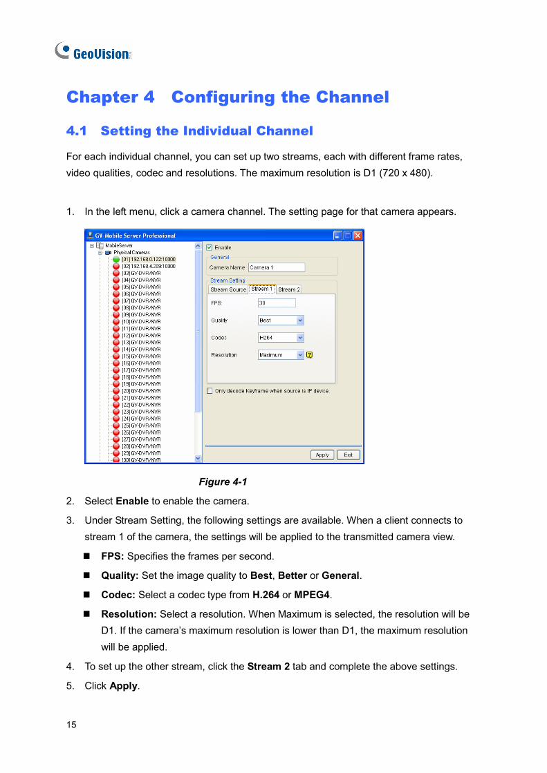
For each individual channel, you can set up two streams, each with different frame rates, video qualities, codec and resolutions. The maximum resolution is D1 (720 x 480).
1. In the left menu, click a camera channel. The setting page for that camera appears.
Figure 4-1
2. Select Enable to enable the camera.
3. Under Stream Setting, the following settings are available. When a client connects to stream 1 of the camera, the settings will be applied to the transmitted camera view.
FPS: Specifies the frames per second.
Quality: Set the image quality to Best, Better or General.
Codec: Select a codec type from H.264 or MPEG4.
Resolution: Select a resolution. When Maximum is selected, the resolution will be D1. If the camera’s maximum resolution is lower than D1, the maximum resolution will be applied.
4. To set up the other stream, click the Stream 2 tab and complete the above settings.
5. Click Apply.
Configuring the Channel
16
4
6. In the left menu, right-click a camera channel to access the options below:
View Actual Stream: Watch the camera view received by GV-Mobile Server. If the camera resolution is larger than D1, D1 resolution will be applied. If the camera resolution is lower than D1, the maximum resolution will be applied.
View Encode Stream 1: Watch the camera view according to the settings you specify in step 3 for stream 1.
View Encode Stream 2: Watch the camera view according to the settings you specify in step 3 for stream 2.
17
4.2 Setting the Matrix Channel
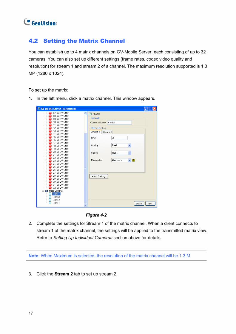
You can establish up to 4 matrix channels on GV-Mobile Server, each consisting of up to 32 cameras. You can also set up different settings (frame rates, codec video quality and resolution) for stream 1 and stream 2 of a channel. The maximum resolution supported is 1.3 MP (1280 x 1024).
To set up the matrix:
1. In the left menu, click a matrix channel. This window appears.
Figure 4-2
2. Complete the settings for Stream 1 of the matrix channel. When a client connects to stream 1 of the matrix channel, the settings will be applied to the transmitted matrix view. Refer to Setting Up Individual Cameras section above for details.
Note: When Maximum is selected, the resolution of the matrix channel will be 1.3 M.
3. Click the Stream 2 tab to set up stream 2.
Configuring the Channel
18
4
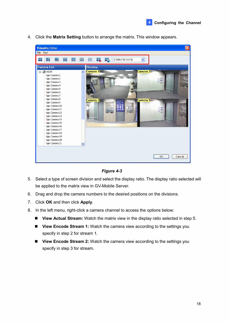
4. Click the Matrix Setting button to arrange the matrix. This window appears.
Figure 4-3
5. Select a type of screen division and select the display ratio. The display ratio selected will be applied to the matrix view in GV-Mobile Server.
6. Drag and drop the camera numbers to the desired positions on the divisions.
7. Click OK and then click Apply.
8. In the left menu, right-click a camera channel to access the options below:
View Actual Stream: Watch the matrix view in the display ratio selected in step 5.
View Encode Stream 1: Watch the camera view according to the settings you specify in step 2 for stream 1.
View Encode Stream 2: Watch the camera view according to the settings you specify in step 3 for stream.
19
Chapter 5 Accessing the Live View
5.1 Using GV-IP Decoder Box / GV-Pad
There are two ways to access GV-Mobile Server channels from GV-IP Decoder Box / GV-Pad:
• To add channels one by one, see Displaying Channels by Browsing in this section.
• To add multiple channels at a time, Displaying Channels Using GV IP Device Utility in this section.
Note: The GV-Mobile Server, GV-IP Decoder Box / GV-Pad and GV-IP Device Utility must be installed under the same LAN.
Accessing Channels by Browsing
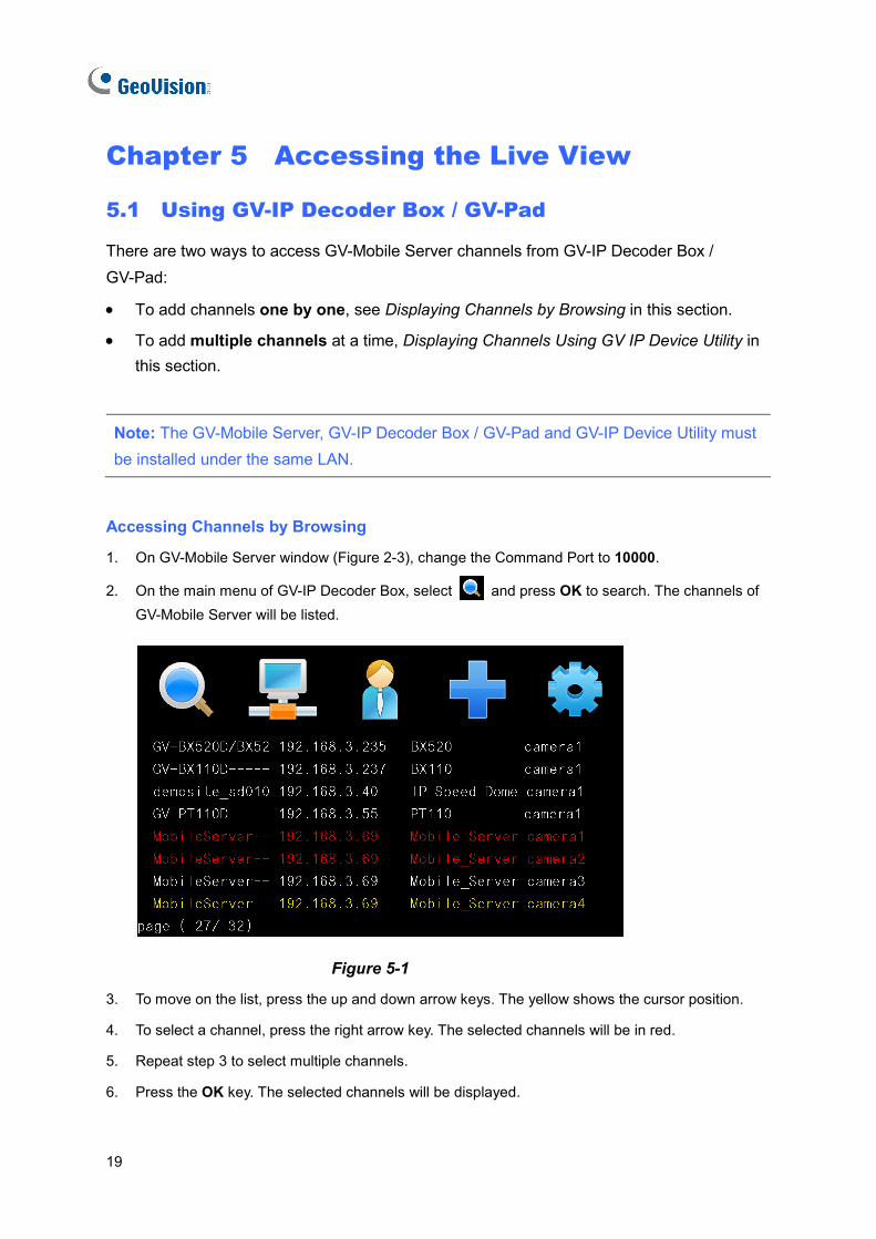
1. On GV-Mobile Server window (Figure 2-3), change the Command Port to 10000.
2. On the main menu of GV-IP Decoder Box, select and press OK to search. The channels of GV-Mobile Server will be listed.
Figure 5-1
3. To move on the list, press the up and down arrow keys. The yellow shows the cursor position.
4. To select a channel, press the right arrow key. The selected channels will be in red.
5. Repeat step 3 to select multiple channels.
6. Press the OK key. The selected channels will be displayed.
Accessing the Live View
20
5
Note: The GV-IP Decoder Box supports Stream 1 and H.264 codec only.
Accessing Channels Using GV IP Device Utility
1. Make sure you have installed the GV IP Device Utility program from GV-IP Decoder Box and
GV-Pad Software DVD.
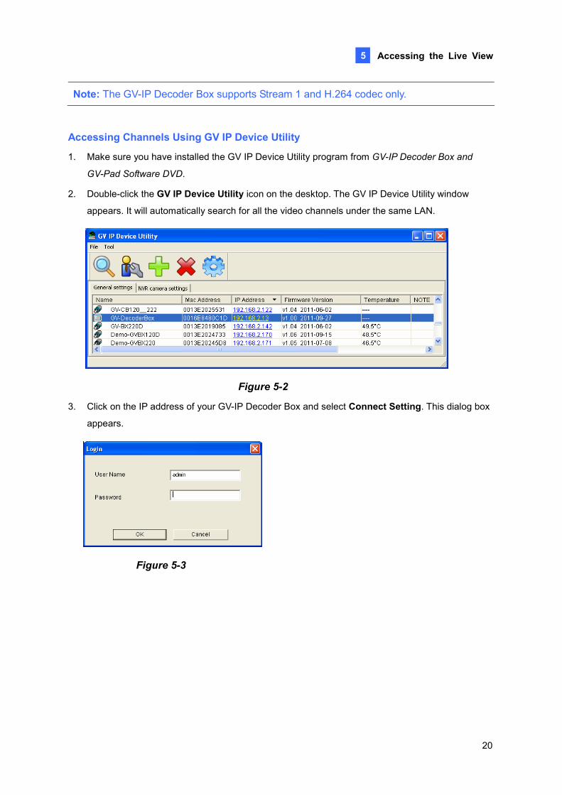
2. Double-click the GV IP Device Utility icon on the desktop. The GV IP Device Utility window
appears. It will automatically search for all the video channels under the same LAN.
Figure 5-2
3. Click on the IP address of your GV-IP Decoder Box and select Connect Setting. This dialog box
appears.
Figure 5-3
21
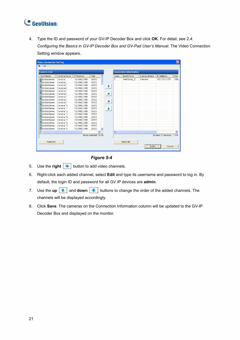
4. Type the ID and password of your GV-IP Decoder Box and click OK. For detail, see 2.4.
Configuring the Basics in GV-IP Decoder Box and GV-Pad User’s Manual. The Video Connection
Setting window appears.
Figure 5-4
5. Use the right button to add video channels.
6. Right-click each added channel, select Edit and type its username and password to log in. By
default, the login ID and password for all GV IP devices are admin.
7. Use the up and down buttons to change the order of the added channels. The
channels will be displayed accordingly.
8. Click Save. The cameras on the Connection Information column will be updated to the GV-IP
Decoder Box and displayed on the monitor.
Accessing the Live View
22
5
5.2 Using iPhone / iPod Touch / iPad
Follow the steps below to access GV-Mobile Server channels from iPhone, iPod Touch and iPad:
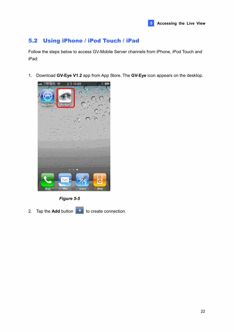
1. Download GV-Eye V1.2 app from App Store. The GV-Eye icon appears on the desktop.
Figure 5-5
2. Tap the Add button to create connection.
23
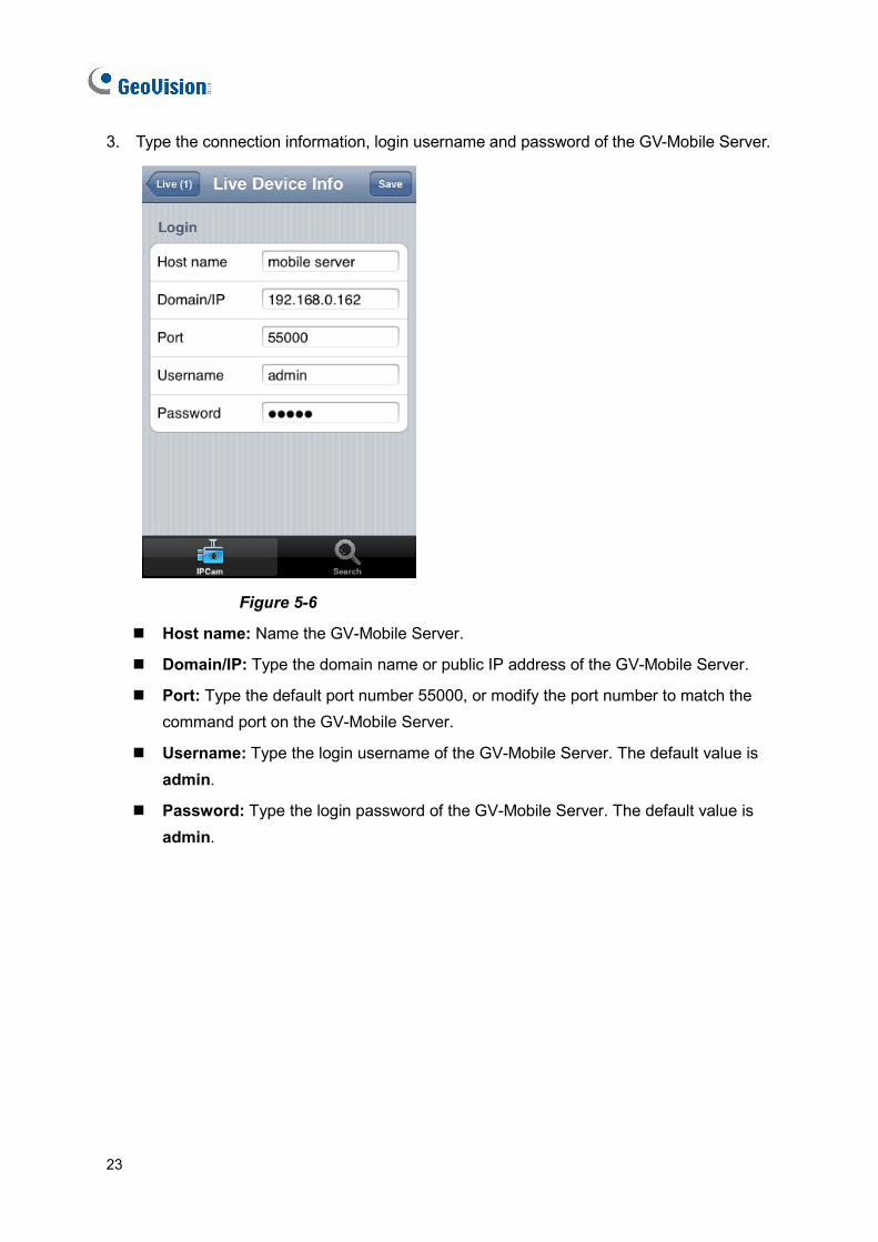
3. Type the connection information, login username and password of the GV-Mobile Server.
Figure 5-6
Host name: Name the GV-Mobile Server.
Domain/IP: Type the domain name or public IP address of the GV-Mobile Server.
Port: Type the default port number 55000, or modify the port number to match the command port on the GV-Mobile Server.
Username: Type the login username of the GV-Mobile Server. The default value is admin.
Password: Type the login password of the GV-Mobile Server. The default value is admin.
Accessing the Live View
24
5
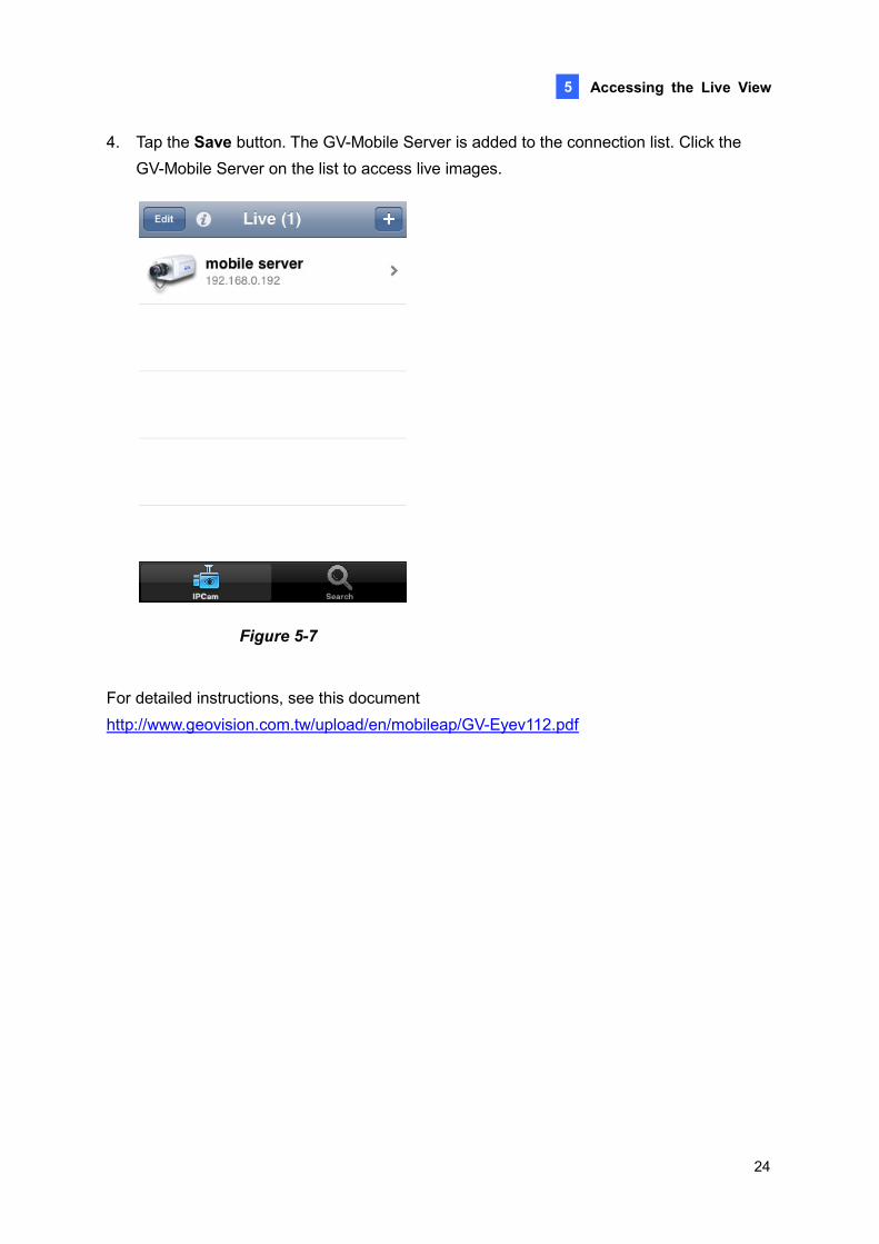
4. Tap the Save button. The GV-Mobile Server is added to the connection list. Click the GV-Mobile Server on the list to access live images.
Figure 5-7
For detailed instructions, see this document 2http://www.geovision.com.tw/upload/en/mobileap/GV-Eyev112.pdf
25
5.3 Using Android Smartphone / Tablet
Follow the steps below to access GV-Mobile Server channels from Android Smartphone or tablet:
1. Download GV-Eye V1.2 app from Android market. The GV-Eye icon appears on the
desktop.
Figure 5-8
2. Tap the GV-Eye icon, and then the login page appears.
Accessing the Live View
26
5
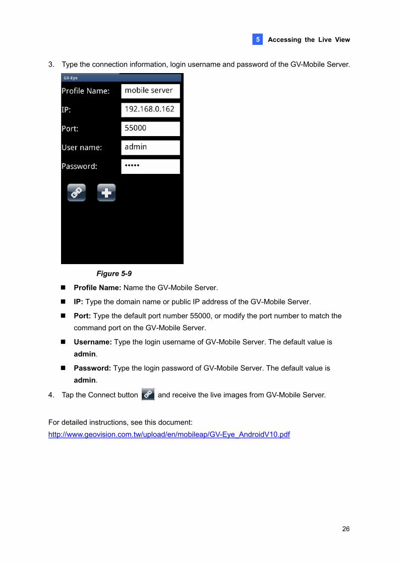
3. Type the connection information, login username and password of the GV-Mobile Server.
Figure 5-9
Profile Name: Name the GV-Mobile Server.
IP: Type the domain name or public IP address of the GV-Mobile Server.
Port: Type the default port number 55000, or modify the port number to match the command port on the GV-Mobile Server.
Username: Type the login username of GV-Mobile Server. The default value is admin.
Password: Type the login password of GV-Mobile Server. The default value is admin.
4. Tap the Connect button and receive the live images from GV-Mobile Server.
For detailed instructions, see this document: 2http://www.geovision.com.tw/upload/en/mobileap/GV-Eye_AndroidV10.pdf
27
5.4 Using Third-Party Surveillance Software
To allow third-party software to connect to GV-Mobile Server through RTSP protocol, complete the settings below.
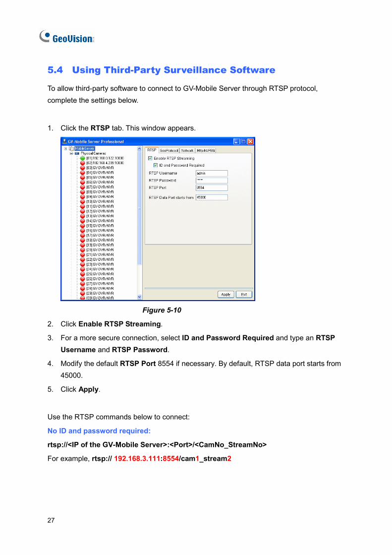
1. Click the RTSP tab. This window appears.
Figure 5-10
2. Click Enable RTSP Streaming.
3. For a more secure connection, select ID and Password Required and type an RTSP Username and RTSP Password.
4. Modify the default RTSP Port 8554 if necessary. By default, RTSP data port starts from 45000.
5. Click Apply.
Use the RTSP commands below to connect:
No ID and password required:
rtsp://<IP of the GV-Mobile Server>:<Port>/<CamNo_StreamNo>
For example, rtsp:// 192.168.3.111:8554/cam1_stream2
Accessing the Live View
28
5
ID and password required:
rtsp://<ID>:<Password>@<IP of the GV-Mobile Server>:<Port>/<CamNo_StreamNo>
For example, rtsp://admin:[email protected]:8554/cam1_stream2
Note: The 4 matrix channels can be accessed using camera number 33 to 36. For example, the RTSP command for the second matrix channel may be rtsp://admin:[email protected]:8554/cam34_stream1
To create a matrix channel, see 4.2 Setting Matrix Channels.
29
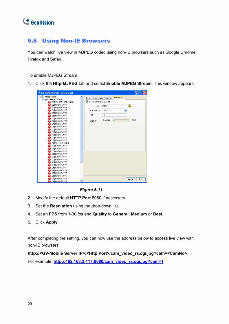
5.5 Using Non-IE Browsers
You can watch live view in MJPEG codec using non-IE browsers such as Google Chrome, Firefox and Safari.
To enable MJPEG Stream:
1. Click the Http-MJPEG tab and select Enable MJPEG Stream. This window appears.
Figure 5-11
2. Modify the default HTTP Port 8080 if necessary.
3. Set the Resolution using the drop-down list.
4. Set an FPS from 1-30 fps and Quality to General, Medium or Best.
5. Click Apply.
After completing the setting, you can now use the address below to access live view with non-IE browsers:
http://<GV-Mobile Server IP>:<Http Port>/cam_video_rs.cgi.jpg?cam=<CamNo>
For example, 2http://192.168.3.117:8080/cam_video_rs.cgi.jpg?cam=1
Setting Up the Router
30
6
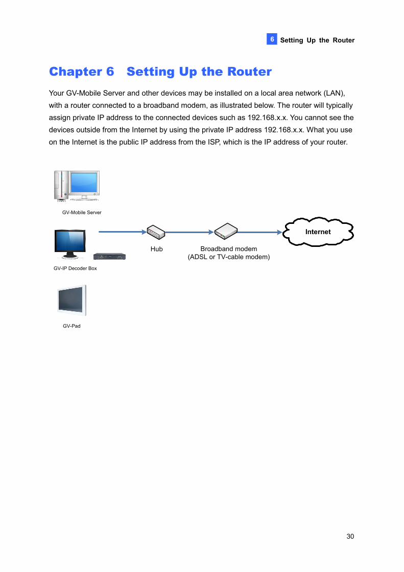
Chapter 6 Setting Up the Router Your GV-Mobile Server and other devices may be installed on a local area network (LAN), with a router connected to a broadband modem, as illustrated below. The router will typically assign private IP address to the connected devices such as 192.168.x.x. You cannot see the devices outside from the Internet by using the private IP address 192.168.x.x. What you use on the Internet is the public IP address from the ISP, which is the IP address of your router.
GV-Mobile Server
GV-IP Decoder Box
GV-Pad
Internet
Broadband modem (ADSL or TV-cable modem)
Hub
31
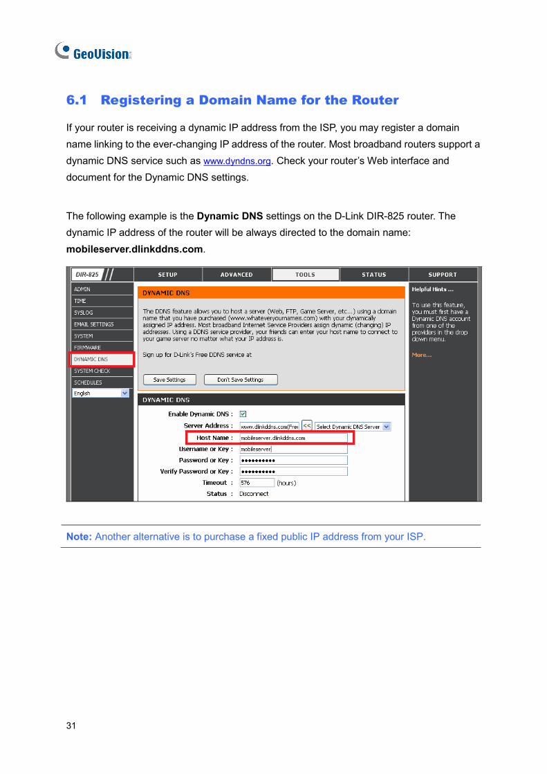
6.1 Registering a Domain Name for the Router
If your router is receiving a dynamic IP address from the ISP, you may register a domain name linking to the ever-changing IP address of the router. Most broadband routers support a dynamic DNS service such as www.dyndns.org. Check your router’s Web interface and document for the Dynamic DNS settings.
The following example is the Dynamic DNS settings on the D-Link DIR-825 router. The dynamic IP address of the router will be always directed to the domain name: mobileserver.dlinkddns.com.
Note: Another alternative is to purchase a fixed public IP address from your ISP.
Setting Up the Router
32
6
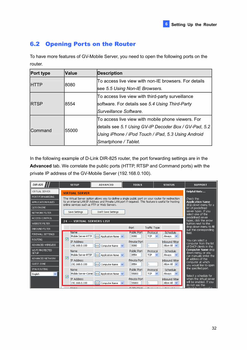
6.2 Opening Ports on the Router To have more features of GV-Mobile Server, you need to open the following ports on the router.
Port type Value Description
HTTP 8080 To access live view with non-IE browsers. For details see 5.5 Using Non-IE Browsers.
RTSP 8554 To access live view with third-party surveillance software. For details see 5.4 Using Third-Party Surveillance Software.
Command 55000
To access live view with mobile phone viewers. For details see 5.1 Using GV-IP Decoder Box / GV-Pad, 5.2 Using iPhone / iPod Touch / iPad, 5.3 Using Android Smartphone / Tablet.
In the following example of D-Link DIR-825 router, the port forwarding settings are in the Advanced tab. We correlate the public ports (HTTP, RTSP and Command ports) with the private IP address of the GV-Mobile Server (192.168.0.100).
33
[Non-IE browsers]
After you open HTTP port 8080 on the router, you can use the address below to access live view with non-IE browsers:
http://<Router’s IP or domain name>:<Http Port>/cam_video_rs.cgi.jpg?cam=<CamNo>
For example, 2http://mobileserver.dlinkddns.com:8080/cam_video_rs.cgi.jpg?cam=1
[RTSP command]
After you open RTSP port 8554 on the router, you can use the command below to access live view:
No ID and password required:
rtsp://< Router’s IP or domain name >:<Port>/<CamNo_StreamNo>
For example, rtsp://mobileserver.dlinkddns.com:8554/cam1_stream2
ID and password required:
rtsp://<ID>:<Password>@<IP of the GV-Mobile Server>:<Port>/<CamNo_StreamNo>
For example, rtsp://admin:[email protected]:8554/cam1_stream2
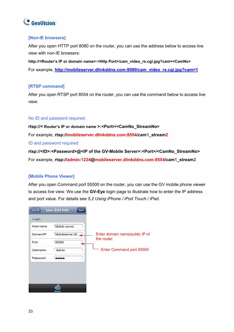
[Mobile Phone Viewer]
After you open Command port 55000 on the router, you can use the GV mobile phone viewer to access live view. We use the GV-Eye login page to illustrate how to enter the IP address and port value. For details see 5.2 Using iPhone / iPod Touch / iPad.
Enter domain name/public IP of the router.
Enter Command port 55000
Specifications
34
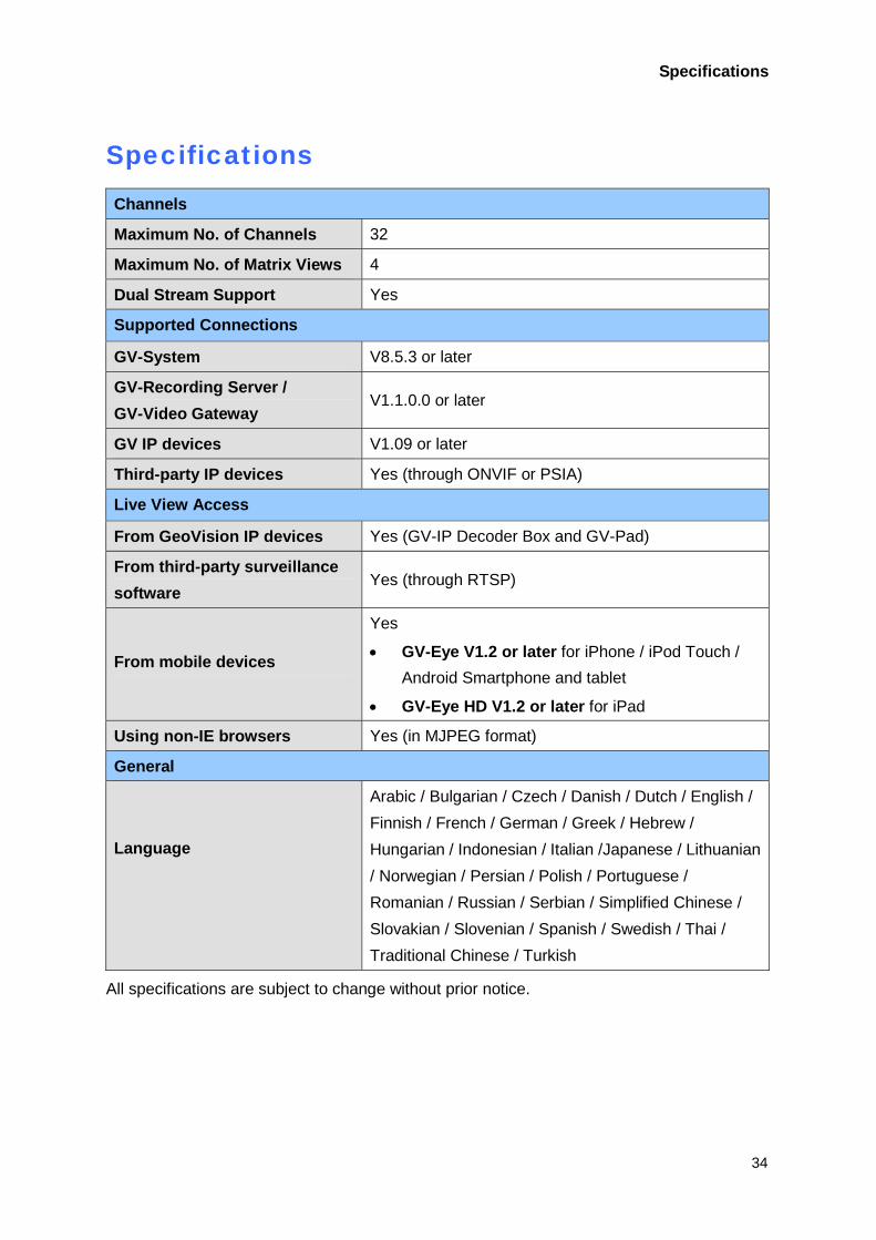
Specifications Channels
Maximum No. of Channels 32
Maximum No. of Matrix Views 4
Dual Stream Support Yes
Supported Connections
GV-System V8.5.3 or later
GV-Recording Server / GV-Video Gateway
V1.1.0.0 or later
GV IP devices V1.09 or later
Third-party IP devices Yes (through ONVIF or PSIA)
Live View Access
From GeoVision IP devices Yes (GV-IP Decoder Box and GV-Pad)
From third-party surveillance software
Yes (through RTSP)
From mobile devices
Yes
• GV-Eye V1.2 or later for iPhone / iPod Touch / Android Smartphone and tablet
• GV-Eye HD V1.2 or later for iPad
Using non-IE browsers Yes (in MJPEG format)
General
Language
Arabic / Bulgarian / Czech / Danish / Dutch / English / Finnish / French / German / Greek / Hebrew / Hungarian / Indonesian / Italian /Japanese / Lithuanian / Norwegian / Persian / Polish / Portuguese / Romanian / Russian / Serbian / Simplified Chinese / Slovakian / Slovenian / Spanish / Swedish / Thai / Traditional Chinese / Turkish
All specifications are subject to change without prior notice.