Guide to programming a Rako wireless module system using ...
19
Guide to programming a Rako wireless module system using Rasoft Table of Contents Perform basic health check of the system...................................................................... 2 Start programming the system......................................................................................... 2 Create a new Rasoft Project File.......................................................................................2 Choose and Set A House Number.................................................................................... 3 Create Rooms and Channel Names..................................................................................4 Address Modules ............................................................................................................... 6 “Ident” Wireless Module........................................................................................................................... 6 Set the Wallplate Addresses............................................................................................. 7 Create Scenes..................................................................................................................... 8 Set the Power-Up Modes................................................................................................... 9 Appendix 1: Group Settings & Ignores.......................................................................... 10 Whole House Commands....................................................................................................................... 10 Changing the Ignore Settings ............................................................................................................... 11 APPENDIX 2: Connecting Rasoft to a Programming Adapter ..................................... 12 1- RAUSB................................................................................................................................................. 12 2- Bridges (RA & RTC)............................................................................................................................ 13 3- RAH-Smart........................................................................................................................................... 15 Check that RAH-Smart communicates with RASOFT.......................................................................... 15 Check & Install Drivers for RAH-Smart................................................................................................. 15 SET RAH-Smart House Address ........................................................................................................... 17 Appendix 3: Programming RAH-Smart.......................................................................... 18 Page 1 of 19
Transcript of Guide to programming a Rako wireless module system using ...
Guide to programming a Rako wireless module system using Rasoft Table of ContentsPerform basic health check of the system...................................................................... 2
Start programming the system......................................................................................... 2
Create a new Rasoft Project File.......................................................................................2
Choose and Set A House Number.................................................................................... 3
Create Rooms and Channel Names..................................................................................4
Address Modules ...............................................................................................................6
“Ident” Wireless Module........................................................................................................................... 6
Set the Wallplate Addresses............................................................................................. 7
Create Scenes.....................................................................................................................8
Set the Power-Up Modes................................................................................................... 9
Appendix 1: Group Settings & Ignores.......................................................................... 10
Whole House Commands....................................................................................................................... 10
Changing the Ignore Settings ............................................................................................................... 11
APPENDIX 2: Connecting Rasoft to a Programming Adapter..................................... 12
1- RAUSB................................................................................................................................................. 12
2- Bridges (RA & RTC)............................................................................................................................ 13
3- RAH-Smart........................................................................................................................................... 15
Check that RAH-Smart communicates with RASOFT.......................................................................... 15
Check & Install Drivers for RAH-Smart................................................................................................. 15
SET RAH-Smart House Address ........................................................................................................... 17
Appendix 3: Programming RAH-Smart.......................................................................... 18
Page 1 of 19

Perform basic health check of the system
The default settings for a Rako module when first connected is to turn on to full power. At factory settings all dimmer modules and keypads are set to the same address, therefore an unprogrammed system will bring all lights on and have basic control from a keypad. If lights do not come on or control panels do not operate the lights then there is a fundamental problem which should be overcome before attempting any further programming.
If the system responds correctly to this basic test, then proceed confidently to program the system.
Start programming the system
Rako wireless modules can be programmed from a Rako control panel (see the instructions that come with a control panel) or from a PC and the RASOFT software. This method requires the use of a Rako programming interface, either a RAUSB, RAH-Smart or a Bridge module. To connect any of these to the system see Appendix 2
Having connected a programming device confirm communication on default settings before changing house number.
Create a new Rasoft Project File
Start up the RASOFT software on the Laptop PC. The main Rako home screen should appear. If any error messages occur during program load, select ignore or OK.
Notice that this screen only has “Rako” written at top left hand corner. This means we are editing the default Rako project file.
Press “File” then “New” to clear out any information from previous Projects (saving these first if necessary).
Then press “Save” to create a new project file.
Page 2 of 19

Press the “Save and edit” button.Give the file an appropriate name and save it in a folder that can be found later.(Wireless Demo in this instance)
Now the project file is called “Wireless Demo”Go to the “Controls” – “Communications” screen & select the correct programming adapter settings (see Appendix 2)
Hint. Once the file has been saved it is better to open it by double clicking on it directly from the Windows desktop. Don’t open Rasoft then use “File” – “Open” as this causes re-initialisation of the communications to the RAUSB or Bridge & is time consuming.
Choose and Set A House Number
Every Rako Wireless system has to be allocated a House Number. This might be a random number or a memorable number such as the house number of the property in question. NOTE: The factory default is House 1, leaving the system with this House Number leaves the installation prone to interference from other Rako systems. If for example the property number is 1 it is STRONGLY recommended to pick another number even if it's still based on the number 1, for example 101, 111, 201 etc. There are 255 possible numbers to choose from. Don't leave it at 1.
Setting the House number
See Appendix 2 for the means of setting a house number for the appropriate programming device.
Page 3 of 19
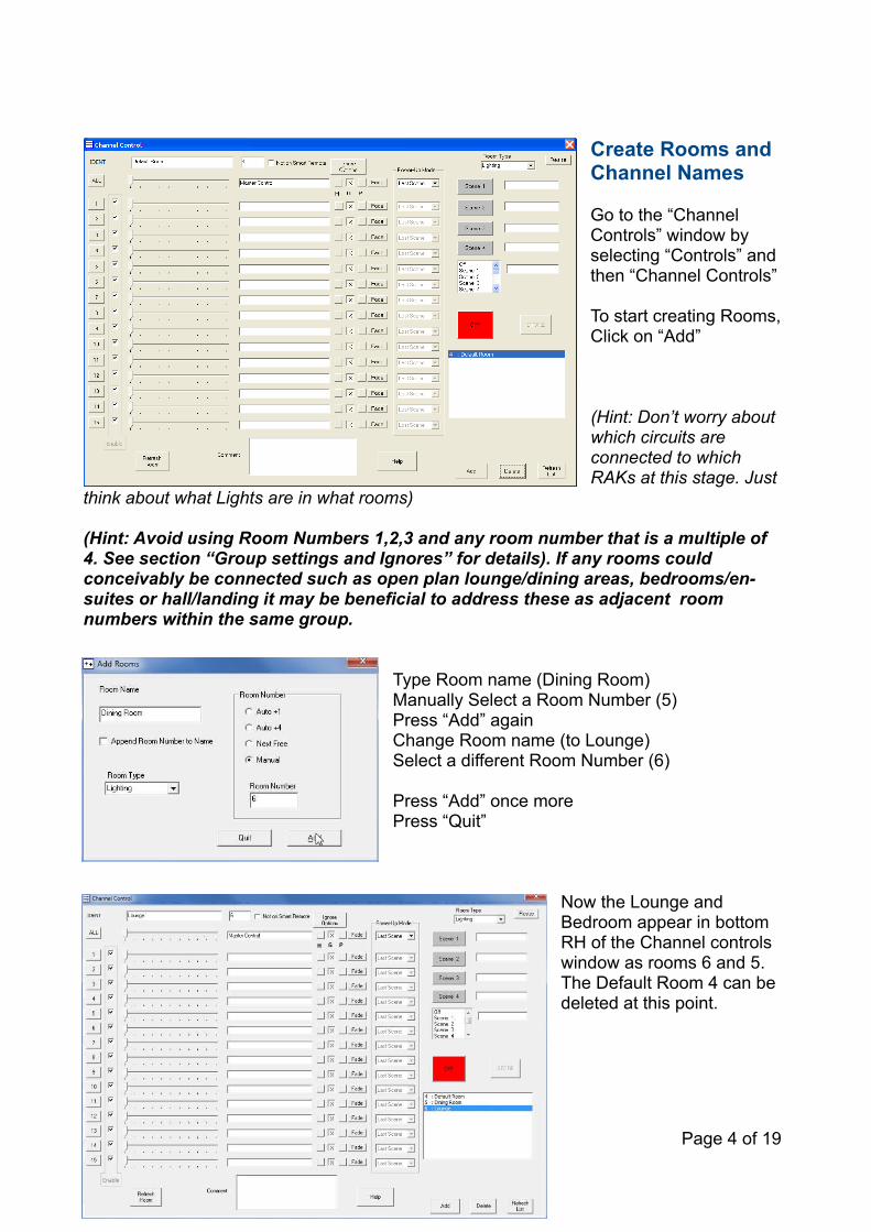
Create Rooms and Channel Names
Go to the “Channel Controls” window by selecting “Controls” and then “Channel Controls”
To start creating Rooms, Click on “Add”
(Hint: Don’t worry about which circuits are connected to which RAKs at this stage. Just
think about what Lights are in what rooms)
(Hint: Avoid using Room Numbers 1,2,3 and any room number that is a multiple of 4. See section “Group settings and Ignores” for details). If any rooms could conceivably be connected such as open plan lounge/dining areas, bedrooms/en-suites or hall/landing it may be beneficial to address these as adjacent room numbers within the same group.
Type Room name (Dining Room)Manually Select a Room Number (5)Press “Add” againChange Room name (to Lounge)Select a different Room Number (6)
Press “Add” once morePress “Quit”
Now the Lounge and Bedroom appear in bottom RH of the Channel controls window as rooms 6 and 5.The Default Room 4 can be deleted at this point.
Page 4 of 19
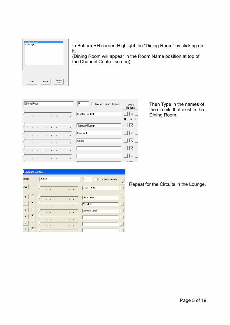
In Bottom RH corner: Highlight the “Dining Room” by clicking on it. (Dining Room will appear in the Room Name position at top of the Channel Control screen).
Then Type in the names of the circuits that exist in the Dining Room.
Repeat for the Circuits in the Lounge.
Page 5 of 19

Address Modules
It is simple to add Wireless Modules to the system. Rako manufacture a wide range of such modules for a variety of purposes. Examples include:
RDL250 Leading edge 250W dimmer RDL500 Leading edge 500W dimmerRDT500 Trailing edge 500W dimmerRDL1200 Leading edge 1200W dimmerRDF800 0-10V 800W dimmer RDS800 800W switch moduleRDDSI DSI 800W dimmerRDDALI DALI 800W dimmerRACUB curtain/blind controllerRLED18-1ACI 18w constant current dimming LED driver.RLED36-3DCI 3 channel (RGB) 36w constant current dimming LED driver. RLED50-1DCV 50w constant voltage dimming LED driver RLED90-3DCV 3 channel (RGB) 90W constant voltage dimming LED driver. RDC300 DC dimmer
Firstly, connect the Wireless Module to its load and connect it to the ac supply. If it is a lighting circuit, then applying power should bring the light onto full brightness.
Assuming that the Wireless Module is still set to its factory settings: Check the circuit responds to a Wall Plate set to House 1, Room 4 (The factory Default).
“Ident” Wireless Module
The module must be allocated a Channel within a room in the Rasoft project file. Use the Channel Control screen.
Select the room that the module is to be used in.
Hold a magnet steady against the side of the module next to the location of its internal LED. When the magnet is in correct location the LED will light up.
Keep the magnet in position for a few seconds until the LED starts to blink in a steady rhythm.
This indicates that the module is ready to be set to its correct channel.
Page 6 of 19
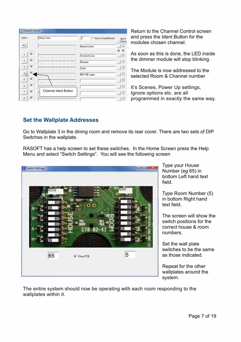
Return to the Channel Control screen and press the Ident Button for the modules chosen channel.
As soon as this is done, the LED inside the dimmer module will stop blinking.
The Module is now addressed to the selected Room & Channel number
It’s Scenes, Power Up settings, Ignore options etc. are all programmed in exactly the same way.
Set the Wallplate Addresses
Go to Wallplate 3 in the dining room and remove its rear cover. There are two sets of DIP Switches in the wallplate.
RASOFT has a help screen to set these switches. In the Home Screen press the Help Menu and select “Switch Settings”. You will see the following screen
Type your House Number (eg 65) in bottom Left hand text field.
Type Room Number (5) in bottom Right hand text field.
The screen will show the switch positions for the correct house & room numbers.
Set the wall plate switches to be the same as those indicated.
Repeat for the other wallplates around the system.
The entire system should now be operating with each room responding to the wallplates within it.
Page 7 of 19
Channel Ident Button
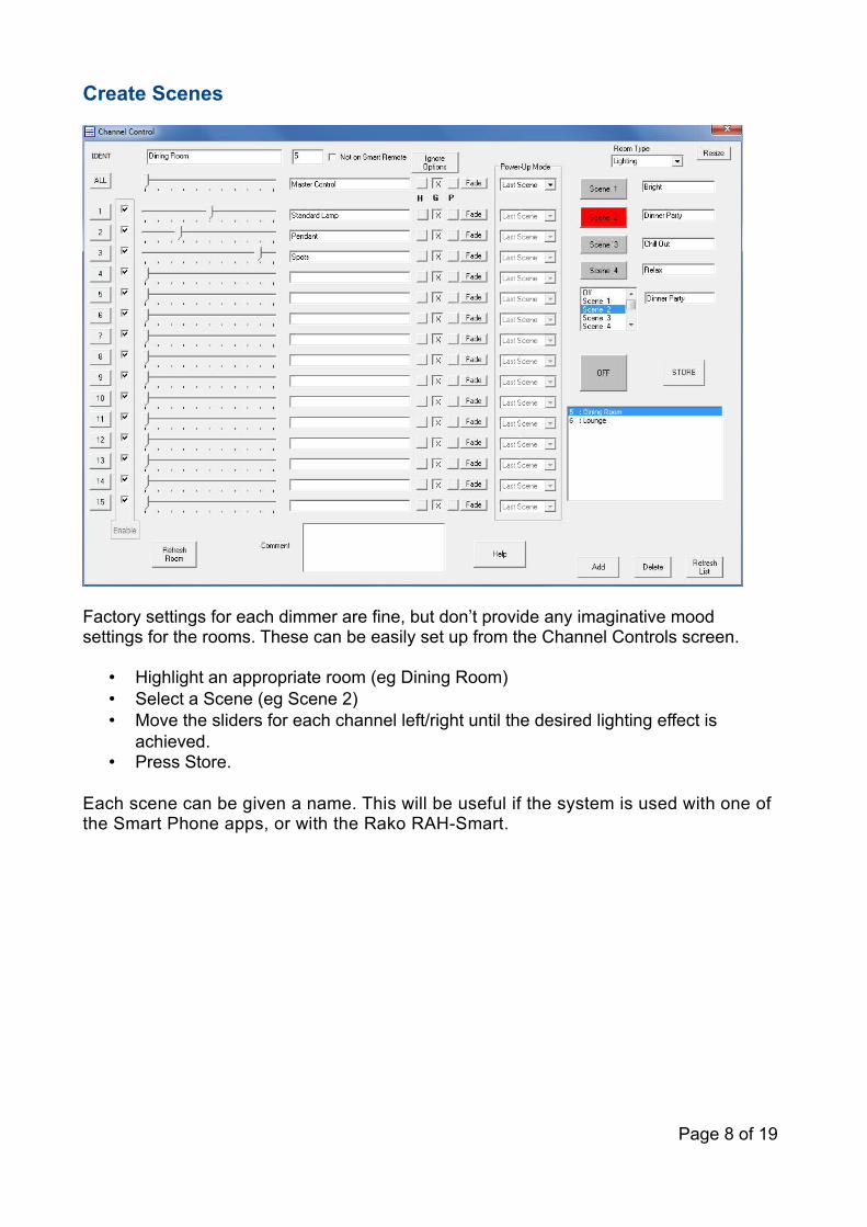
Create Scenes
Factory settings for each dimmer are fine, but don’t provide any imaginative mood settings for the rooms. These can be easily set up from the Channel Controls screen.
• Highlight an appropriate room (eg Dining Room)• Select a Scene (eg Scene 2)• Move the sliders for each channel left/right until the desired lighting effect is
achieved.• Press Store.
Each scene can be given a name. This will be useful if the system is used with one of the Smart Phone apps, or with the Rako RAH-Smart.
Page 8 of 19

Set the Power-Up Modes
With the circuits responding to the Channel Controls, the Power-Up modes need to be set.When power is applied to a dimmer it can either fade up the lights, or leave them off – depending on the programming. This is an important setting as it tells the system what to do after a power cut. Generally, it is bad if all the lights come on after a power cut.
Click on the Power-Up Mode drop down box at the top of the Channel Control screen. The list shows the different settings available to the dimmers.
The default setting for a dimmer is 100%. This means that when power is applied to the dimmer it will turn the lights up to maximum. This is a very useful setting during installation & commissioning as it makes it easy to check that circuits are working. However – it is generally bad to use this as the final setting since it will cause lights to come on after supply interruptions.
The most used options are:Last Scene: The dimmer will restore the same state that it was in before the power was removed. So – if the light was On before the power cut, it will come back on afterwards. If it was off before the cut, it will stay off.
Off: Whatever the state of the light before the power cut, the light will stay off when the power is restored.
The “Per Channel” option allows each dimmer in a room to have its own individual Power-Up setting if that is needed.
Hint: make sure the dimmers are really set to the required power-up setting. Rasoft does not send the dimmers the Power-Up setting unless the setting is manually selected from drop down menu. Just because it’s displaying “Last Scene” doesn’t mean that it has actually transmitted that to the dimmers.
The Power-Up setting needs to be done in each room.
Test the power up settings by switching off all the breakers, then switching back on.
Page 9 of 19

Appendix 1: Group Settings & IgnoresGroup setting allows dimmers to respond to commands from different rooms.Group Settings are typically used where a single area is split into two or three sub areas: Examples are Kitchen/Diner areas, Bedroom/Ensuite, Hallway/Landing.
In the Rako systems, room numbers are either Group Masters of Group Members. Any room number that is a multiple of four can act as a Master for the following three room numbers. Thus Room 4 is a Master for Group Member rooms 5,6,7. Room 8 is Master for rooms 9,10,11 and so on.
The Group Members can be programmed to respond to (or ignore) any of their group Master commands.
Whole House Commands
Room zero commands can be used to control every room in the house. The most common application is a “Whole House Off” commands which can be sent from a Wall Plate located by the main exit of the building.
Group Example:Hallway – Room 9Landing – Room 10
Each of these areas will have their own wall controller. A room 9 controller for the hallway and a room 10 controller for the landing. But it is also possible to fit room 8 controllers (at top & bottom of the stairs perhaps). The programming can be such that the room 8 controllers set lighting in both the landing and the hallway when climbing the stairway.
Generally it is simpler if rooms are only given Group Member room numbers. (Room numbers 1,2,3 are also to be avoided. This is because the Group Master for these rooms is Room Zero).
So number rooms as 5,6,7,9,10,11,13,14,15,17,18,19 etc. Avoid using Room numbers 1,2,3,4,8,12,16,20,24,28 etc.
When allocating room numbers consider which rooms will benefit from being within the same group as each other. Typically a Bedroom and it’s En-suite Bathroom may be grouped or Front External Lights could be grouped with Rear External Lighting.
Page 10 of 19
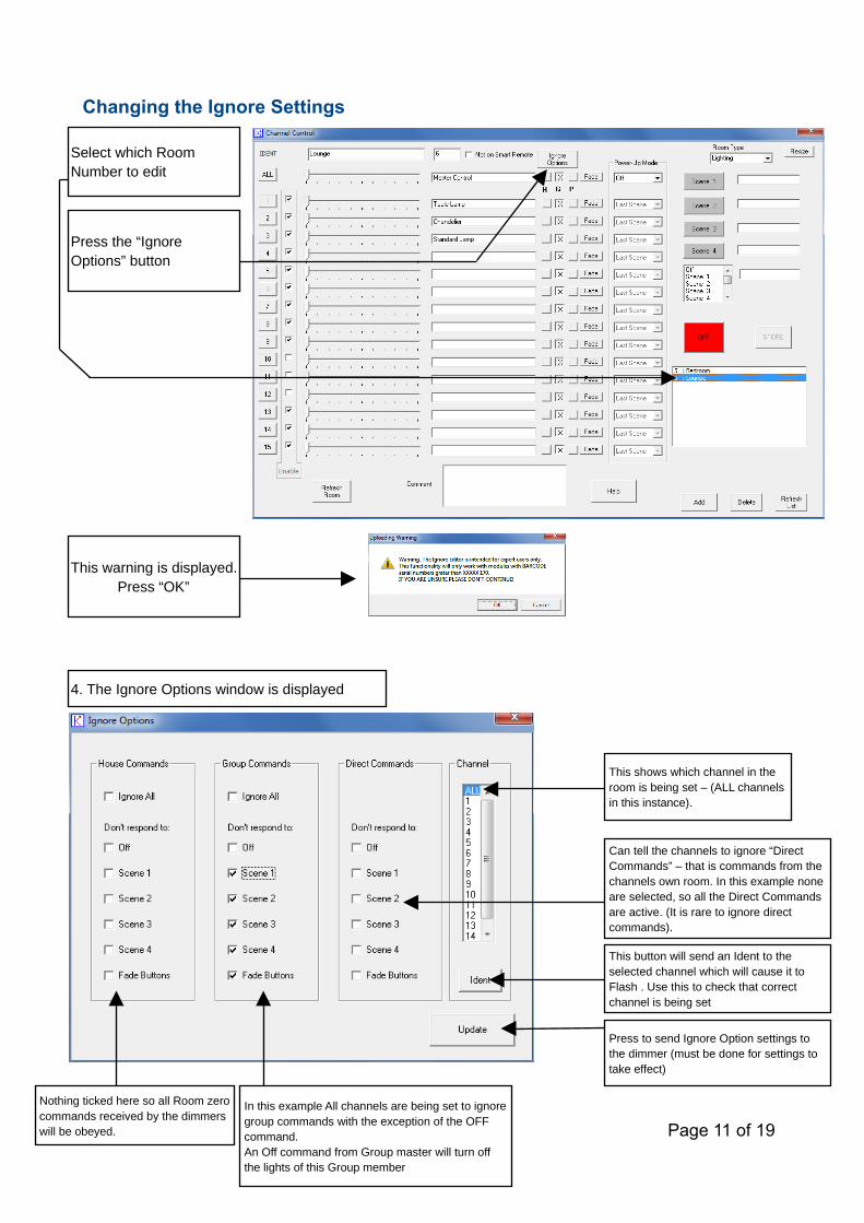
Changing the Ignore Settings
Page 11 of 19
Select which Room Number to edit
Press the “Ignore Options” button
This warning is displayed.Press “OK”
4. The Ignore Options window is displayed
This shows which channel in the room is being set – (ALL channels in this instance).
Can tell the channels to ignore “Direct Commands” – that is commands from the channels own room. In this example none are selected, so all the Direct Commands are active. (It is rare to ignore direct commands).
This button will send an Ident to the selected channel which will cause it to Flash . Use this to check that correct channel is being set
Press to send Ignore Option settings to the dimmer (must be done for settings to take effect)
In this example All channels are being set to ignore group commands with the exception of the OFF command.An Off command from Group master will turn off the lights of this Group member
Nothing ticked here so all Room zero commands received by the dimmers will be obeyed.
APPENDIX 2: Connecting Rasoft to a Programming Adapter
Rasoft needs to be connected to the Rako system by a Programming Adapter. There are several modules that can be used:
• RAUSB - Most commonly used adapter used by installers for programming Wireless Systems
• RAHSmart – Rako handheld remote controller that can be connected to PC via USB
• RA & RTC Bridges – Interface for Smart Phone apps. Can be used to program wireless systems. Connects to PC by Ethernet.
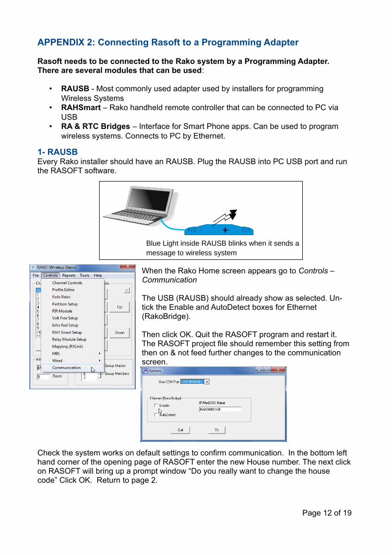
1- RAUSBEvery Rako installer should have an RAUSB. Plug the RAUSB into PC USB port and run the RASOFT software.
When the Rako Home screen appears go to Controls – Communication
The USB (RAUSB) should already show as selected. Un-tick the Enable and AutoDetect boxes for Ethernet (RakoBridge).
Then click OK. Quit the RASOFT program and restart it. The RASOFT project file should remember this setting from then on & not feed further changes to the communication screen.
Check the system works on default settings to confirm communication. In the bottom left hand corner of the opening page of RASOFT enter the new House number. The next click on RASOFT will bring up a prompt window “Do you really want to change the house code” Click OK. Return to page 2.
Page 12 of 19
Blue Light inside RAUSB blinks when it sends a message to wireless system
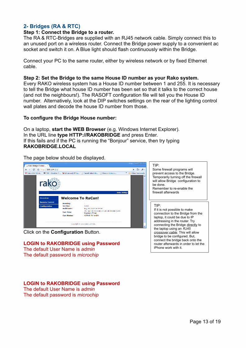
2- Bridges (RA & RTC)Step 1: Connect the Bridge to a router. The RA & RTC-Bridges are supplied with an RJ45 network cable. Simply connect this to an unused port on a wireless router. Connect the Bridge power supply to a convenient ac socket and switch it on. A Blue light should flash continuously within the Bridge.
Connect your PC to the same router, either by wireless network or by fixed Ethernet cable.
Step 2: Set the Bridge to the same House ID number as your Rako system.Every RAKO wireless system has a House ID number between 1 and 255. It is necessary to tell the Bridge what house ID number has been set so that it talks to the correct house (and not the neighbours!). The RASOFT configuration file will tell you the House ID number. Alternatively, look at the DIP switches settings on the rear of the lighting control wall plates and decode the house ID number from those.
To configure the Bridge House number:
On a laptop, start the WEB Browser (e.g. Windows Internet Explorer).In the URL line type HTTP://RAKOBRIDGE and press Enter. If this fails and if the PC is running the “Bonjour” service, then try typing RAKOBRIDGE.LOCAL
The page below should be displayed.
Click on the Configuration Button.
LOGIN to RAKOBRIDGE using PasswordThe default User Name is adminThe default password is microchip
LOGIN to RAKOBRIDGE using PasswordThe default User Name is adminThe default password is microchip
Page 13 of 19
TIP:Some firewall programs will prevent access to the Bridge. Temporarily turning off the firewall will allow Bridge configuration to be done.Remember to re-enable the firewall afterwards
TIP:If it is not possible to make connection to the Bridge from the laptop, it could be due to IP addressing in the router. Try connecting the Bridge directly to the laptop using an RJ45 crossover cable. This will allow bridge to be configured. But, connect the bridge back onto the router afterwards in order to let the iPhone work with it.

When successfully logged in, the screen below will be displayed:
Change the House ID number to match that of the RAKO system. Then press the Save Config button.
On the laptop, Run Rako Lighting RASOFT program. After a short delay the Rasoft start up screen will be displayed.
Page 14 of 19
House ID Number
This error message will probably appear after changing the configuration. This is normal. Just click OK
Tip: Do not have any Rako USB or RS232 devices connected to your computer as these will interfere with the Bridge setup process
Tip: It can take a minute or two from connecting the bridge to the router & switching it on, before RASOFT is able to talk to it .
• Select the Controls – Communication Menu Item.
• Tick the Ethernet Bridge “Enable” and “Autodetect” check boxes.
• Select “Disable COM Port” if this option is shown.
• Close & reopen RASOFT
Rasoft start up screen

3- RAH-Smart
Check that RAH-Smart communicates with RASOFT
Remove battery cover to reveal mini USB connector. Connect to PC using mini USB/USB lead provided.
Run the RASOFT Program. If the PC and the RAH-Smart are communicating correctly then the RAH-Smart Display will show a Transmit Symbol each time a scene button is pressed on the RASOFT Home screen.
If RASOFT is not communicating with the RAH-Smart then check that the correct driver has installed.
Check & Install Drivers for RAH-Smart
When Windows detects the RAH-Smart for the first time it will attempt to load drivers for it. Occasionally the wrong drivers are installed. To correct this:
Check the Device Driver by looking in the Windows Control Panel<>System<>Device Manager.
Page 15 of 19
Correctly Installed RAH-Smart Driver
Wrongly Installed RAH-Smart Driver
Transmit symbol flashes when a message is sent to the wireless system.
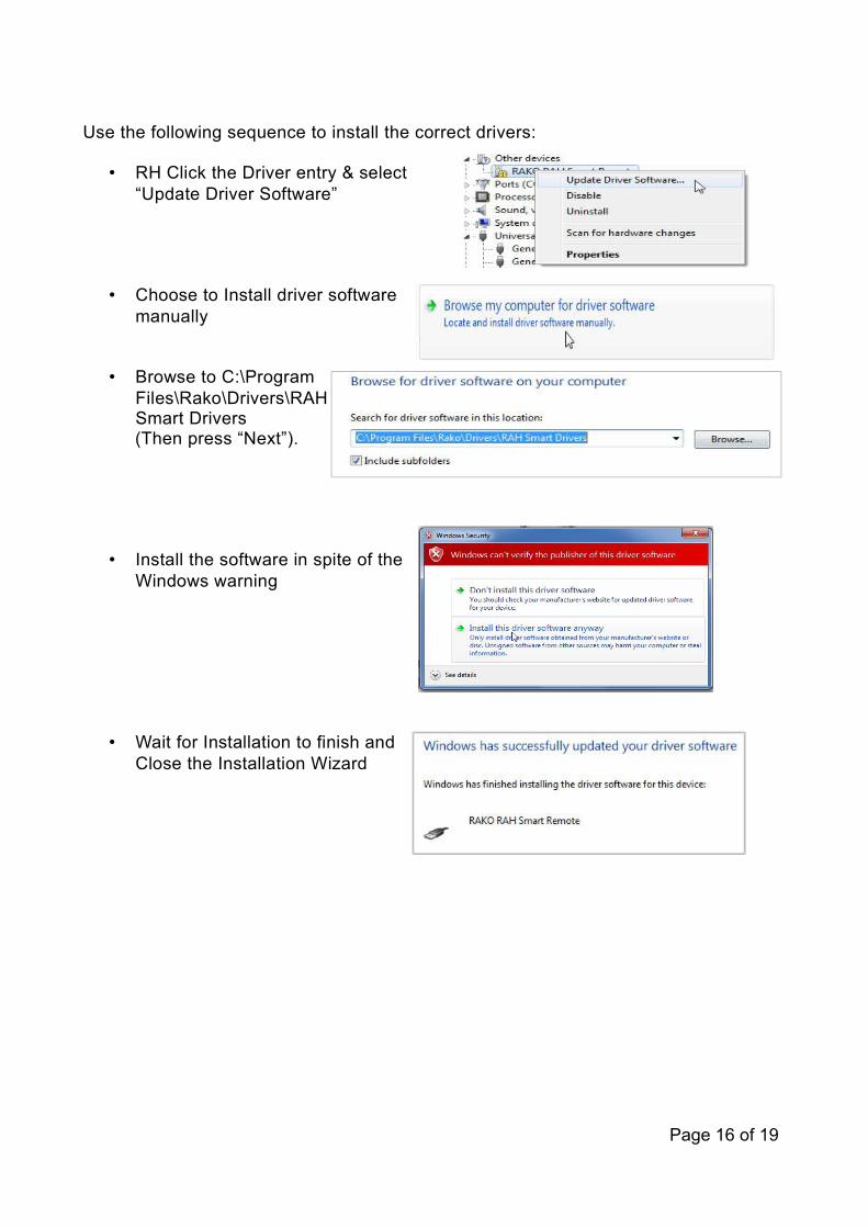
Use the following sequence to install the correct drivers:
• RH Click the Driver entry & select “Update Driver Software”
• Choose to Install driver software manually
• Browse to C:\Program Files\Rako\Drivers\RAH Smart Drivers
(Then press “Next”).
• Install the software in spite of the Windows warning
• Wait for Installation to finish and Close the Installation Wizard
Page 16 of 19
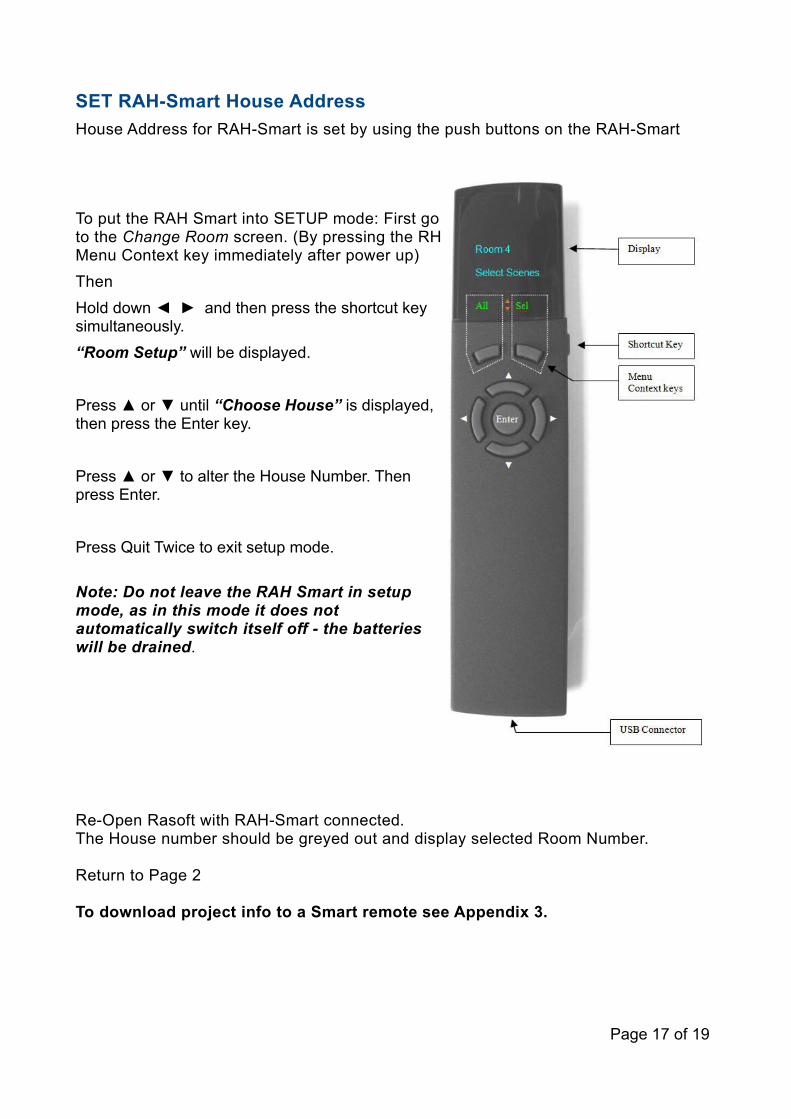
SET RAH-Smart House Address
House Address for RAH-Smart is set by using the push buttons on the RAH-Smart
To put the RAH Smart into SETUP mode: First go to the Change Room screen. (By pressing the RH Menu Context key immediately after power up)
Then
Hold down ◄ ► and then press the shortcut key simultaneously.
“Room Setup” will be displayed.
Press ▲ or ▼ until “Choose House” is displayed, then press the Enter key.
Press ▲ or ▼ to alter the House Number. Then press Enter.
Press Quit Twice to exit setup mode.
Note: Do not leave the RAH Smart in setup mode, as in this mode it does not automatically switch itself off - the batteries will be drained.
Re-Open Rasoft with RAH-Smart connected. The House number should be greyed out and display selected Room Number.
Return to Page 2
To download project info to a Smart remote see Appendix 3.
Page 17 of 19

Appendix 3: Programming RAH-Smart
Programming RAH-Smart from RASOFT is quick and easy.RASOFT takes the Room information from the Channel Controls screen and uploads it to the RAH-Smart so that these rooms can be controlled from the RAH-Smart.
• From the Rasoft Home Screen select “RAH Smart Setup” from the Controls drop down menu.
• The RAH Smart Configuration screen shown below will appear.
Page 18 of 19

The RAH Smart configuration screen shows a list a rooms that it has taken from the Channel Control setup screen.
• Press the “Get Room Data” button.
The Rooms, Channels, Scenes counts below the button will be updated.
• Press the “Upload” button in the bottom right hand corner of the RAH Smart configuration screen.
This will send the information to the RAH Smart.
The RAH Smart is now programmed and ready to use. In most cases this is all that needs to be done.
Page 19 of 19