Guidance on the use of Tactile Paving Surfaces
108
I?.. , !E!: R T RANSPORT R EGIONS Guidance on the use of Tactile Paving Surfaces
Transcript of Guidance on the use of Tactile Paving Surfaces

~' I?..,!E!: R T RANSPORT
R EGIONS
Guidance on the use of Tactile Paving Surfaces


CONTENTS
Introduction
Mobility of visually impaired people
Using these guidelines
The role of consultation
WARNING SURFACES
Chapter 1
Blister Surface For Pedestrian Crossing Points
1.1
1.2
1.3
1.4
1.5
Purpose
Definition
Application
Maintenance
1.4.1 Condition of surface
1.4.2 New Roads and Street Works Act
Layout
1.5.1 Controlled crossings:
1.5.1.1 Colour
1.5.1.2 General layout
1.5.1.3 Overlapping crossings
1.5.1.4 Private forecourts
1.5.1.5 Pedestrian refuges and other larger pedestrian islands
1.5.2 Uncontrolled crossings:
1.5.2.1 Colour
1.5.2.2 General layout
9
12
14
19
19
22
24
27
27
27
27
27
28
28
32
32
34
34
34
35
1

Guidance on the use of Tactile Paving Surfaces
1.5.2.3 Inset (indented) crossings
1.5.2.4 In-line uncontrolled crossings
1.5.2.5 Acute angled junctions
1.5.2.6 Crossing away from a junction
1.5 .2. 7 Pedestrian refuges
1.5.3 Pedestrian refuges and other larger pedestrian islands:
1.5.3.1 Standard pedestrian refuge
1.5.3.2 Staggered pedestrian island
1.5.3.3 Triangular pedestrian islands
1.5.4 Vehicle crossovers and vehicle accesses:
1.5.4.1 General layout
1.5.4.2 Vehicle crossovers with high traffic flows
1.5.4.3 Vehicle crossovers to residential properties
1.5.5 Traffic calming:
1.5.5.1 General layout
1.5.5.2 Side road entry treatments
1.5.5.3 Entire junction treatments
1.5.6 Conservation areas:
1.5.6.1 Colour
1.5. 7 Inspection covers:
1.5. 7.1 Blister surface inlays
1.5.8 Partially pedestrianised areas
Chapter 2
Corduroy Hazard Warning Surface
2.1 Purpose
2.2 Definition
2.3 Application
2
35
38
38
38
42
42
42
42
45
45
45
47
48
48
48
48
48
51
51
51
51
52
53
53
53
55
-~

Contents
2.4 Maintenance 55
2.4.1 Condition of surface 55
2.4.2 New Roads and Street Works Act 56
2.5 Layout 56
2.5.1 Generallayout 56
2.5.2 Steps 56
2.5.3 Ramps to light rapid transport (LRT) platforms 58
2.5.4 Level crossings 58
2.5.5 Entrance to platform area in an unprotected rail station 59
2.5.6 Shared facilities 59
Chapter 3
Platform Edge (Off~Street) Warning Surface 63
3.1 Purpose 63 3.2 Definition 63
3.3 Application 63
3.4 Maintenance 65
3.4.1 Condition of surface 65 3.5 Layout 65
Chapter4
Platform Edge (On~Street) Warning Surface 67
4.1 Purpose 67
4.2 Definition 67
4.3 Application 69
4.4 Maintenance 69
4.4.1 Condition of surface 69
3

Guidance on the use of Tactile Paving Surfaces
4.4.2 New Roads and Street Works Act
4.5 Layout
69
70
ChapterS
Segregated Shared Cycle Track/Footway Surface and Central Delineator Strip 71
4
5.1 Purpose
5.2 Definition
5.3 Application
5.4 Maintenance
5.4.1 Condition of surface
5.4.2 New Roads and Street Works Act
5.5 Layout
5.5.1 General layout
71
73
73
74
74
74
74
74
5.5.2 Junctions: 76
5.5.2.1 Junction where a footway joins a shared route 76
5.5.2.2 Junction where a cycle track joins a shared route 77
5.5.2.3 Junction where a shared route joins another shared route 77
5.5.2.4 Vehicular access route across a shared route - an uncontrolled crossing 80
5.5.2.5 Vehicular access route across a shared route - a controlled crossing 80
5.5.2.6 Controlled crossings along a shared route 81

AMENITY SURFACES
Chapter 6
Guidance Path Surface
6.1 Purpose
6.2 Definition
6.3 Application
6.4 Maintenance
6.4.1 Condition of surface
6.4.2 New Roads and Street Works Act
6.5 Layout
6.5.1 General layout
6.5.2 Bends and junctions
Chapter 7
Information Surface
7.1 Purpose
7.2 Definition
7.3 Application
7.4 Maintenance
7 .4.1 Condition of surface
7.4.2 New Roads and Street Works Act
7.5 Layout
Glossary
Contacts
Reference Documents
Contents
89
89
89
91
91
91
92
92
92
93
97
97
97
98
98
98
98
99
101
103
104
5

Guidance on the use of Tactile Paving Surfaces
FIGURES
1 Dropped kerb detail (prior to installation of tactile paving) 21
2 Profile and plan of blister surface 23
3 Layout of blister surface at controlled crossing point 29
4 Layout of blister surface at controlled crossing where the back of the edge of the tactile is not parallel to the kerb. 31
5 Overlapping controlled crossings 33
6 (Indented) uncontrolled crossing point at a side road 36
7 Layout of blister surface at in-line uncontrolled crossing point 39
8 Layout of blister surface at indented uncontrolled crossing at acute angled junction 40
9 Uncontrolled crossing away from a junction 41
10 Layout of blister surface on standard refuge less than 2m wide 43
11 Layout of blister surface on standard refuge 2m or more wide 43
12 Layout of blister surface on staggered pedestrian island 44
13 Location of blister surface on triangular pedestrian island 46
14 Vehicle crossovers and vehicle accesses 47
15 Layout of blister surface at kerb to kerb flat top road hump 49
16 Layout of blister surface at a side road junction where the side road carriageway has been raised to the level of the footway 49
17 Layout of blister surface at a junction where the entire junction carriageway has been raised to the level of the footway 50
18 Inspection cover that has been inlaid with blister surface 52
19 Profile and plan of corduroy surface 54
20 Layout of corduroy surface at top and bottom of flight of stairs 57
21 Layout of corduroy surface where ramp access is immediately adjacent to steps 60
6 :_ -iC

Contents
22 Layout of corduroy surface at ramps to light rapid transit platform on street 61
23 Layout of corduroy surface at level crossings 62
24 Profile and plan of platform edge (off street) warning surface 64
25 Layout of platform edge (off street) warning surface 66
26 Profile and plan of platform edge (on street) warning surface 68
27 Layout of platform edge (on street) warning surface 70
28 Profile and plan of the tactile surface (shared routes) 72
29 Layout of the tactile surface on pedestrian and cyclist sides 75
30 Layout of tactile surface and central delineator strip at a junction where a footpath joins a shared route on the pedestrian side (A) and on the cyclist side (B) 78
31 Layout of tactile surface and central delineator strip at a junction where a cycleway joins a shared route on the cyclist side (A) and the pedestrian side (B) 79
32 Junction where shared route joins another shared route 82
33 Layout of tactile surfaces at a junction between a shared route and a carriageway - uncontrolled crossings 83
34 Tactile surface arrangement at side road junctions -controlled crossings 84
35 Tactile surface arrangement at controlled crossings along a shared route 85
36 Profile and plan of guidance path surface 90
37 Layout of guidance path surface at right angle tum 94
38 Layout of guidance path surface at a tum other than a right angle 95
39 Layout of guidance path surface at a "T" junction and at a crossroads 96
40 Layout of information surface 100
7


Introduction
Mobility of Visually Impaired People
The nature of visual impairment
There are approximately 1 million blind and partially sighted adults in the United Kingdom. Approximately 5% of these people have no sight at all. The remainder have varying degrees of residual sight which may enable them to function visually to different degrees.
The nature of visual loss varies considerably between individuals. The overall picture is a complex one, but generally the result of different eye conditions will lead to the following types of impairment:
• a limited field of vision - being unable to see to the sides or up and down;
• some loss of central vision -limiting the ability to see fine detail;
• acute shortsightedness - seeing the world as a continuous blur;
• uncontrollable oscillations of the eyeball- leading to an inability to see objects clearly; and
• night blindness -a sensitivity to light and a tendency to be dazzled by glare.
Mobility techniques
Visually impaired people will either move around independently or with the aid of a sighted person who will act as a guide.
9

Guidance on the use of Tactile Paving Surfaces
Those who move around independently will do so either solely by using their residual sight or by using a mobility aid.
The most common mobility aid used by pedestrians with poor sight to facilitate their independent mobility is a long white cane. This is used to scan the ground in front of the person.
The scanning takes the form of sweeping the cane in an arc from one side to the other to just beyond the width of the body. This technique will usually locate potential obstructions such as street furniture, provided that there is some element at ground level, and distinct changes in level such as a kerb upstand or a step.
An increasing number of people are using a long cane with a roller tip. The roller tip maintains contact with the ground as the cane is swept and may indicate the presence of distinct changes in texture underfoot, as well as the features usually detected by the more traditional type of long cane.
Once any feature has been located and possibly identified, the pedestrian will decide how to proceed.
Alternatively, a visually impaired person may have a guide dog to assist them with their mobility. There are approximately 4,500 guide dog owners in the UK, but this will increase in the future.
A guide dog is trained to lead its owner around obstructions and to stop at distinct changes of level, for example, a kerb upstand, a flight of steps, or a hole in the ground. Guide dogs are generally unable to respond to changes in texture or colour underfoot.
If a guide dog stops at a particular feature, for example a kerb edge, the owner has to decide how and when to proceed.
It is clear therefore that a visually impaired person walking independently without the benefit of a mobility aid such as a long cane or a guide dog may only recognise the edge of the footway by stepping off a conventional kerb.
10

Introduction
It is also the case that whatever mobility aid is being used, a kerb upstand is an essential indicator of the edge of the footway. However, in recognition of the needs of other pedestrians, it is accepted that it is necessary to have level or ramped crossing points in certain locations. In such locations, tactile paving compensates for the absence of a kerb.
Key design principles
There are certain key design principles which, when applied, make it easier and safer for visually impaired pedestrians to move around.
Layouts of all pedestrian areas should be simple, logical and consistent. This will enable people to memorise environments that they use regularly and predict and interpret environments that they are encountering for the first time.
Contrasts in colour and tone should be used to accentuate the presence of certain key features. This will enable many people to use their residual vision to obtain information.
Orientation and wayfinding information should be provided by the use of high visibility and, where appropriate, tactile signing. Many visually impaired people can read signs if they are properly positioned, and if the design incorporates contrasting colours and tones, adequately sized and styled text, and a matt finish.
Lighting levels should be even and adequate and should minimise glare. Once again, this will enable effective use to be made of residual vision, especially to detect contrasts in colour and tone and read high visibility signs.
Important information about the environment should be conveyed by the use of non-visual features, for example, audible and tactile features. A loss of sight is not accompanied by an increase in the effectiveness of other non-visual senses. However, visually impaired people generally place more emphasis on information received via other senses, for example the sense of touch.
11

Guidance on the use of Tactile Paving Surfaces
The use of tactile information
When moving around the pedestrian environment, visually impaired people will actively seek and make use of tactile information underfoot, particularly detectable contrasts in surface texture.
The ability to detect contrasts in texture underfoot varies from one individual to another. For example, older visually impaired people and people who have lost their sight through certain medical conditions, such as diabetes, may well have reduced sensitivity in their feet. It is therefore important that textures warning of potential hazards, for example a road crossing or a staircase, are rigorous enough to be detectable by most people but without constituting a trip hazard or causing extreme discomfort.
Some visually impaired people will receive training in mobility skills, especially those who are using a long cane or a guide dog. Increasingly, this training includes instruction in the interpretation of tactile paving. The Joint Mobility Unit, a service provided by the Royal National Institute for the Blind (RNIB) and the Guide Dogs for the Blind Association (GDBA) is producing a self-instructional training pack which informs visually impaired people of the different tactile paving surfaces and their prescribed meanings.
For more information about the way in which visually impaired people move around contact the Joint Mobility Unit (see Contacts section).
Using these guidelines
Tactile paving surfaces can be used to convey important information to visually impaired pedestrians about their environment, for example, hazard warning, directional guidance, or the presence of an amenity. Research has determined that visually impaired people can reliably detect, distinguish and remember a limited number of different tactile paving surfaces and the distinct meanings assigned to them.
The use of blister paving as a warning device at controlled and uncontrolled pedestrian crossing points is now well established. In this document, guidance is given on the use of a number of additional types of tactile surface to give warning of potential hazards and for amenity purposes to give guidance and information.
12
'-""

Introduction
Recognising that the needs of people with physical and sensory disabilities could create potential conflicts, the research which led to the development of the tactile paving surfaces involved not only the target group, i.e. visually impaired people, but also others with a wide range of other disabilities including wheelchair users and people with walking difficulties.
Each type of tactile paving surface should be exclusively reserved for its intended use and consistently installed in accordance with these guidelines. Visually impaired people are becoming increasingly mobile, both within their local area and more widely, and it is, therefore, very important that conflicting and confusing information is not conveyed.
The successful use of tactile paving also depends on visually impaired pedestrians understanding the different meanings assigned to the paving and being made aware of the presence of such facilities in their area.
Local authorities are advised to investigate how this information can most effectively be disseminated. To assist with this, a self-instructional training pack based upon the guidance contained in this document will shortly be available from the Joint Mobility Unit at the Royal National Institute for the Blind (see Contacts section). It is strongly recommended that local groups representing visually impaired people are consulted before the installation of tactile paving surfaces which provide directional guidance or information about amenities so that they may indicate what will help them most.
The installation of tactile paving surfaces should be considered as part of a wider package of measures to assist visually impaired people. The installation process should involve an assessment of the surrounding environment. In particular, the condition of the surrounding footway should be examined and hazards, for example, uneven pavements removed and obstacles, particularly inappropriately sited street furniture, repositioned. Street works should be carefully inspected to ensure that the standards of reinstatement of any tactile surface meet the performance requirements of the New Roads and Street Works Act 1991 and the associated codes of practice.
13

Guidance on the use of Tactile Paving Surfaces
With the exception of the delineator strip for shared routes (see Chapter 5) none of the tactile surfaces described in this document are regarded as traffic signs. They are not, therefore, included in the Traffic Signs Regulations and General Directions (TSRGD), and do not require authorisation.
The advice in this document has been compiled after full discussion and in full consultation with interested groups and it aims to provide consistency in the use of the tactile paving surfaces throughout the country. The written advice is supported throughout by a series of diagrams. Readers should note, however, that the diagrams are for illustrative purposes only, and are not drawn to scale.
Where local authorities consider implementing policies which deviate from the advice given in this document, they are strongly recommended to consult the Mobility Unit of the Department of the Environment, Transport and the Regions or the Joint Mobility Unit run by the Royal National Institute for the Blind and the Guide Dogs for the Blind Association (see Contacts section) before proceeding. Where local site conditions are such that the guidance contained in this document cannot be implemented, further advice should be sought.
The role of consultation
Tactile paving installers will benefit from consulting with others prior to installation taking place. Such consultation should only take place with those who can demonstrate a good understanding of the ways in which tactile paving should be used.
As previously mentioned, deviation from the principles set out in this document should not take place without prior consultation with the Mobility Unit of the Department of the Environment, Transport and the Regions, or the Joint Mobility Unit ofRNIB/GDBA (see Contacts section).
14

Introduction
Consultation to clarify the requirements of visually impaired people should take place with organisations of, or for, people with visual impairments, and with rehabilitation or mobility officers. This should ensure that the information received reflects the needs of the population as a whole rather than one individual.
Whether national or local groups should be consulted will depend on the nature of the advice or guidance required. National organisations should be contacted if technical solutions are being sought. They are more likely to be aware of solutions that have been successfully developed elsewhere and can help ensure that tactile paving is installed in a manner which is consistent with other parts of the UK. This last point is important as visually impaired people are becoming increasingly mobile throughout the UK as a whole.
Local organisations should be consulted if installers are looking to prioritise where tactile paving is to be installed. This might identify routes that are frequently used by visually impaired people, or locations that are causing particular problems. It is especially important that local organisations are consulted prior to the installation of the amenity surfaces. This will ensure that they are installed where they will be of real benefit.
If any discrepancy arises between the information given by national and local organisations, the two should be asked to reach an agreement.
Local organisations should always be notified in advance of any major changes that are proposed, for example the redesign of a major crossing location, the installation or removal of a controlled crossing, or the change from a zebra to a pelican crossing. This will enable the views of local people to be considered in advance of the changes, and will inform them of new facilities which.may enhance their mobility.
15


Warning Surfaces


CHAPTER 1
Blister Surface For Pedestrian Crossing Points This chapter should be read in conjunction with the advice in the Introduction.
The advice in this chapter supersedes that in Disability Unit Circular 1/91, "The use of dropped kerbs and tactile paving at pedestrian crossing points". It should be applied to new installations or where planned maintenance or reconstruction is carried out.
1.1 Purpose
• The purpose of the blister surface is to provide a warning to visually impaired people who would otherwise, in the absence of a kerb upstand >25mm high, find it difficult to differentiate between where the footway ends and the carriageway begins. The surface is therefore an essential safety feature for this group of road users at pedestrian crossing points, where the footway is flush with the carriageway to enable wheelchair users to cross unimpeded.
The Disabled Persons Act 1981 requires highway authorities to "have regard to the needs of disabled persons when considering the desirability of providing ramps at appropriate places between the carriageways and footways". It is recognised that the absence of an upstand is essential for people using wheelchairs but is potentially hazardous to visually impaired pedestrians who rely on a kerb upstand as a warning that they have reached the edge of the footway. Typically, a kerb upstand is absent when a ramp has been provided between the carriageway and footway as at a crossing; when traffic calming measures have resulted in the level of the carriageway being raised to that of the footway, as at flat top road humps; or when streets have been partially pedestrianised and footways and carriageways are only differentiated by the use of different colours and/or materials.
19

Guidance on the use of Tactile Paving Sutfaces
20
A ramp is provided between the carriageway and footway to assist pedestrians when crossing the road, particularly wheelchair users and others who experience difficulties negotiating kerbs. It is important that ramps are designed appropriately: the maximum gradient should not exceed 1 in 12 (8%), and where space allows, a gradient of 1:20 (5%) should be achieved. It is recognised that on particularly narrow footways and those footways that already have significant gradients, it may be impossible to achieve even the maximum gradient, or to do so only by creating an unacceptable camber for wheelchair users. In those circumstances it is particularly important to discuss any proposals with disabled people locally.
In all cases where the kerb is dropped at pedestrian crossing points there should be no vertical upstand between the road surface and the kerb; a 6mm tolerance can be made but only on a bullnose kerb. (Figure 1 page 21). Even a minimal vertical upstand can be a hazard to wheelchair users.
A detectable kerb upstand prevents visually impaired people from unknowingly stepping off the footway into the carriageway. If there is no kerb upstand, some other readily identifiable indicator must be used.
The tactile surface has been developed in order to provide warning and guidance for visually impaired people where there is no kerb upstand. In the case of controlled crossings the tactile surface layout also acts as a guide to lead visually impaired people to the crossing point.
Alternative approaches to the installation of a tactile surface were suggested, most notably the concept of creating a lower height kerb with a small upstand which would both allow access for wheelchair users and provide a warning for visually impaired people. This idea was not accepted because no optimum upstand could be identified which could meet effectively the needs of both groups of people.
The use of the blister surface at uncontrolled crossings was introduced in the 1990s to resolve the problems experienced by visually impaired pedestrians at flush dropped kerbs away from controlled crossings. . ,
; __ J:.

Blister Surface For Pedestrian Crossing Points
Figure 1: Dropped kerb detail (prior to installation of
blister surface)
~
®
©
Rear of footway
1--- Rear of footway
Taper/Dropper kerb
->s:~~entral kerbs to be flush with carriageway surface (see C) and white for benefit of partially sighted people
To enable existing dropper kerb to be used a larger joint may be necessary if the central kerbs are to be exactly flush with the carriageway
Kerb
Variable width - may, following consultation with disabled people, be extended to rear of footway - but must not be less than that required to achieve a gradient of 8% (1 : 12)
Not greater than 6mm
Footway Preferred carriageway surface level
Notes: 1) Not to scale.
21

Guidance on the use of Tactile Paving Surfaces
The existing profile was developed following a research programme commissioned by the Department of the Environment, Transport and the Regions. In the course of further research, which investigated 20 different tactile profiles using volunteers with many different types of disability as well as non-disabled people, it was found that the original surface could be modified so as to be less uncomfortable, particularly to people with arthritis, whilst remaining detectable to visually impaired people. This modification involved flattening the top of the original rounded blister profile.
1.2 Definition
• The profile of the blister surface comprises rows of flat-topped 'blisters', 5mm (±0.5mm) high (Figure 2 page 23 ).
22
The blister surface can be made of any material suitable for footway pavements. It is most commonly supplied in 400mm sq concrete slabs or smaller block paviors.
Recognising that the needs of people with physical and sensory disabilities could create potential conflicts, the research which led to the development of the tactile surface involved not only the target group, i.e. visually impaired people, but also others with a wide range of other disabilities including wheelchair users and people with walking difficulties.
The original blister surface which comprised rows of rigorous, rounded blisters around 6mm high was modified several years ago to make it less uncomfortable. The original blister surface should no longer be used.
The blister surface takes account of the needs of the widest range of disabled people, including the many visually impaired people who have lost their sight as a result of diabetes - a condition which also often reduces sensitivity in feet and hands. Because of this, the surface must be fairly rigorous. The layouts set out in this document, therefore, aim to reduce any discomfort which may be caused to people with painful conditions such as arthritis by minimising the amount of tactile surface used and by providing clear pathways around it wherever possible. , ,

Blister Surface For Pedestrian Crossing Points
Figure 2: Profile and plan of blister surface
Module type A - 6 domes
~ 1-'1, B· I I ~
***** +-G ****** ***** +- -
***** +-f-
++++++
7 domes _,
I B +++++++
A
-+ + + Module type B
(49 domes) + + +
/. 450 sq. approx. ./ (see table)
++++++ jl B Alternative module type C 1 400 sq. approx. (see table) .\ 2 x 3 domes,_
133
Pitch Dimensions A B
Module s· p e IZe
66.8 33 B 450 s . 64 33 C 200x13 67 33
,_ ________ __......~] 50 min
Notes: 1) Not to scale. 2) All dimensions in millimetres.
Full Size Section
25 dia approx.
(The actual depth will be related to the material used to construct the module)
23

Guidance on the use of Tactile Paving Surfaces
Above all, it should be remembered that the blister surface is provided as an essential warning to visually impaired people.
The use of certain colours in the surface is recommended as many partially sighted people have sufficient residual vision to detect strong contrasts in colour and tone. Installing the surface in a colour and tone which contrasts with the surrounding footway will provide a visual indication of the limits of the footway. At controlled crossings only (see 1.5.1 for definition) the surface should be red to indicate to partially sighted people that the crossing is controlled. Where the surrounding footway or carriageway material is also red then it will be necessary to provide a contrasting border, a minimum of 150mm wide, around the tactile surface. At uncontrolled crossings (see 1.5.2 for definition) the surface should be buff or such a colour (other than red) as provides a contrast with the surrounding surface. Some relaxation of the guidance regarding colour may be acceptable in conservation areas and these are discussed in more detail in 1.5.6.
1.3 Application
The blister tactile surface should be installed in the absence of an upstand at both controlled and uncontrolled crossing points:
• where the footway has been dropped flush with the carriageway; or
• where the carriageway has been raised to the level of the footway.
The surface was originally limited in its use to controlled crossingspelicans, zebras and traffic signals with pedestrian phases. With the development of new types of controlled crossing, the tactile surface is also for use at puffin and toucan crossings.
In 1991, following extensive discussion and consultation, the use of the surfaces was also extended to include uncontrolled crossing points. The tactile surface illustrated in Figure 2 is, therefore, recommended for use at both controlled and uncontrolled crossing points where the footway is flush with the carriageway. At controlled crossings, the surface is also used to lead visually impaired pedestrians to the crossing point.
24

Blister Surface For Pedestrian Crossing Points
It was the consensus opinion of those consulted that the same surface, albeit in different colours and layouts, should be used for both controlled and uncontrolled crossing points. There were three main reasons cited:
• the surface would be serving a similar function for each type of crossing;
• it would be cost effective; and
• it would reserve for other guidance and warning messages the limited number of alternative surfaces which have been shown to be detectable by visually impaired people.
Local authorities are strongly advised to adopt this broader application of the blister surface.
Before installing a crossing, it is essential that local authorities:
• Understand the mobility needs of visually impaired people. Consultation with local groups can play an important part in this process. Details of appropriate local groups can be obtained from the Royal National Institute for the Blind (see Contacts section). Alternatively, local authority rehabilitation workers (in some areas known as mobility officers) or access officers may be able to advise on suitable groups.
• Recognise that schemes which result in carriageways and adjacent footways at the same level, as in partially pedestrianised areas, can be hazardous to visually impaired people. Providing the blister surface along the whole length is expensive and will be confusing. Only at designated crossing points- controlled and uncontrolled - should the kerb be dropped or the carriageway raised to
be flush with the footway. At these locations the blister surface should be provided in the appropriate colour and layout.
• Consider the surrounding environment, taking into account the arrangement of crossing facilities. The condition of the surrounding footway should be examined and hazards, for example, uneven pavements removed and obstacles, for example, street furniture, repositioned.
25

Guidance on the use of Tactile Paving Surfaces
• Establish whether existing dropped kerb facilities are provided in the most suitable location and whether they require the retrospective installation of the blister surface.
• Recognise that the blister surface is part of a wider package of measures to assist visually impaired people.
Facilities such as audible and tactile signals are also key elements in promoting independent mobility for visually impaired people (for further information see Local Transport Note 2/95 'The design of pedestrian crossings', and Traffic Advisory Leaflets 4/91 and 5/91 -see Reference documents section).
Partially sighted people are also assisted by a strong colour contrast at the kerb edge. This can be achieved, for example, by painting or marking the kerb edge white (Figure 1 page 21).
It is accepted that the installation of the blister surface throughout a local area may take place over a long period of time. It is, however, important that the phasing of the work does not confuse, and therefore endanger, visually impaired pedestrians.
It is desirable, for reasons of consistency, to have the blister surface installed at all appropriate locations on an identified pedestrian route, especially busy routes. However, this should not preclude the installation of the surface whenever an individual location is being constructed or refurbished.
It is vitally important that the removal of any existing kerb upstand at a recognised crossing point, is accompanied by the installation of the blister surface. If this is not done, regular users of that route will have no indication that the kerb has been removed and may unknowingly enter the carriageway.
It is equally important that wherever a crossing is decommissioned or relocated the blister surface is removed.
26
Blister Surface For Pedestrian Crossing Points
1.4 Maintenance
1.4.1 Condition of surface
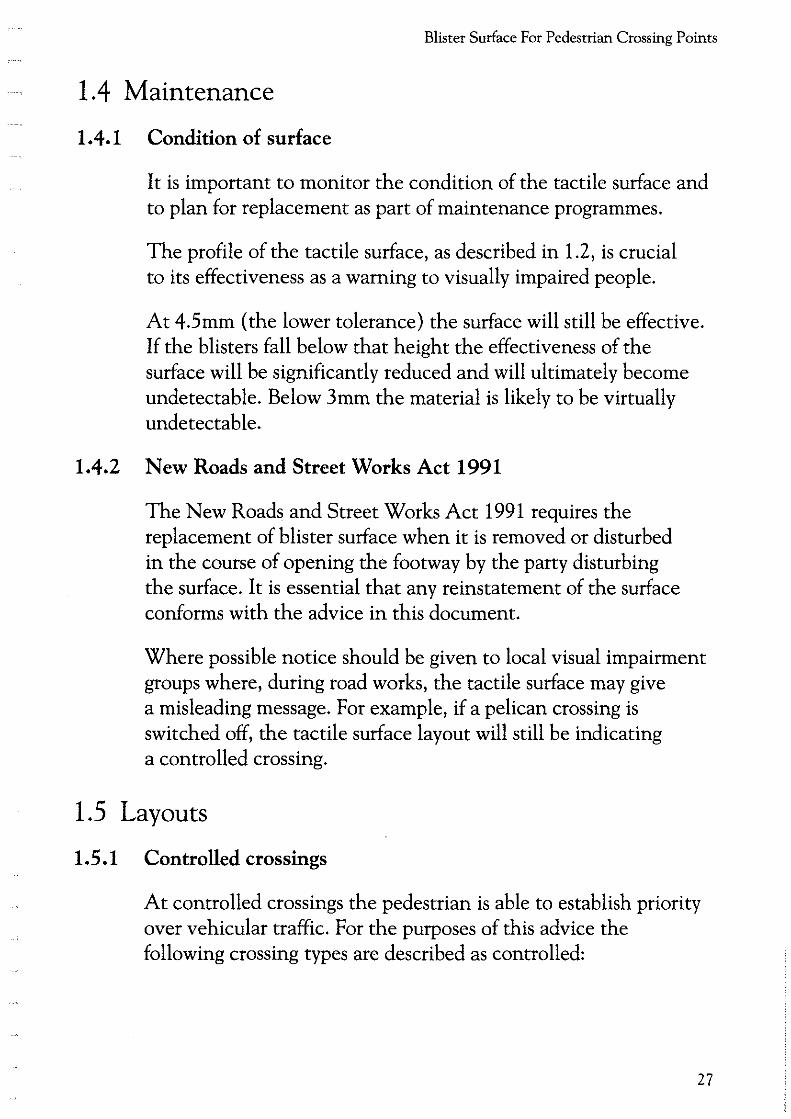
It is important to monitor the condition of the tactile surface and to plan for replacement as part of maintenance programmes.
The profile of the tactile surface, as described in 1.2, is crucial to its effectiveness as a warning to visually impaired people.
At 4.5mm (the lower tolerance) the surface will still be effective. If the blisters fall below that height the effectiveness of the surface will be significantly reduced and will ultimately become undetectable. Below 3mm the material is likely to be virtually undetectable.
1.4.2 New Roads and Street Works Act 1991
The New Roads and Street Works Act 1991 requires the replacement of blister surface when it is removed or disturbed in the course of opening the footway by the party disturbing the surface. It is essential that any reinstatement of the surface conforms with the advice in this document.
Where possible notice should be given to local visual impairment groups where, during road works, the tactile surface may give a misleading message. For example, if a pelican crossing is switched off, the tactile surface layout will still be indicating a controlled crossing.
1.5 Layouts
1.5.1 Controlled crossings
At controlled crossings the pedestrian is able to establish priority over vehicular traffic. For the purposes of this advice the following crossing types are described as controlled:
27

Guidance on the use of Tactile Paving Sutfaces
• Zebras.
• Pelicans.
• Puffins.
• Toucans.
• Traffic signals junctions with pedestrian phases.
1.5.1.1 Colour
• The red blister surface should be used at controlled crossings only. This will further assist partially sighted people to distinguish the presence of a controlled crossing point. It may also be of benefit to sighted pedestrians and may emphasise the presence of a crossing to vehicle drivers.
It is best to avoid using any other red material in the vicinity of a controlled crossing. Where this is unavoidable it will be necessary to provide a contrasting border around the blister surface contrasting in colour and tone. A border 150mm wide should provide sufficient contrast. Where there are conservation considerations an alternative colour for the tactile surface may be appropriate (see 1.5.6).
1.5.1.2 Generallayout
28
• Where the dropped kerb at the controlled crossing is in the direct line of travel, eg. at crossing points on junctions, the tactile surface should be laid to a depth of 1200mm. At all other controlled crossings a depth of 800mm should be provided (Figure 3 page 29) This will ensure that visually impaired pedestrians pick up the surface.
• The back edge (of the section of tactile surface which extends across the dropped kerb) should be at right angles to the direction of crossing (Figure 3 page 29). This may not necessarily be parallel to the kerb.

Blister Surface For Pedestrian Crossing Points
Figure 3: Layout of blister surface at controlled crossing point
"L" pattern tactile surface arrangement for use at Zebras, Pelicans and other signalised crossings
Inset controlled crossing
General Rule 800mm depth across dropped kerb
In-line controlled crossing
General Rule 1200mm depth at in-line controlled crossings
Notes: 1) Not to scale.
Building line
- -
Building line
-
2) Crossing shown is a pelican.
- -- - - -
-- - - -
..
-
..
3) Further advice on the design of controlled crossing is given in Local Transport Note 2/95, "The design of pedestrian crossings".
29

Guidance on the use of Tactile Paving Surfaces
30
'
Some visually impaired people can use the back edge of the tactile surface to align themselves correctly in the direction of crossing. Some may use the direction of the rows of blisters to provide that guidance.
• Where the back edge is not parallel to the kerb, and as a result the depth of the tactile surface varies, it should be no less than 800mm at any point (Figure 4 page 31 ).
• At controlled crossings only, a stem of the surface, 1200mm wide, should extend from the flush dropped kerb to the back of the footway and preferably back to the building line where that is possible. (Figure 3 page 29). The stem will be encountered by visually impaired people walking along the footway and can be followed to the controlled crossing point. It is recognised that in some cases this could result in a very long stem. If this is considered undesirable, local authorities should consult with local visually impaired people and rehabilitation officers (or mobility officers) to establish whether a shorter stem is acceptable. In most cases a 5m long stem should be sufficient.
• The stem should extend back from the tactile paving adjacent to the push button control box or the zebra pole, forming an 'L' arrangement (Figure 3 page 29). The stem can be followed to the push button box or pole which should be adjacent to the right hand side of the crossing area. Positioning the control box on the right hand side is useful for guide dog users who will generally be working their guide dog on their left hand side.
In one-way streets, and on staggered crossings, where the traffic is approaching from the left, then the stem should lead down to a push button on the right hand side, but a second push button should be provided on the left hand side.
• The stem should be installed so that it is in line with the direction of travel across the road (Figures 3 and 4 pages 29 and 31).

Blister Surface For Pedestrian Crossing Points
Figure 4: Layout of blister surface at controlled crossing where the back edge of the tactile is not parallel to the kerb
: .. . : : . . . : ... ..
00 ···~············ .................... . 0 0 0 0 0 •• 0 0......... •• 0 0 •• 0 . 0 ••• 0 ..•••. 0 .......................... 00 •••••••••• ... ................. ....... ... .......... . 00 ••• •••••••••••• ••••••••••••••••••••
Notes: 1) Not to scale.
Guardrailing
2) Crossing shown is a controlled crossing.
31
Guidance on the use of Tactile Paving Surfaces
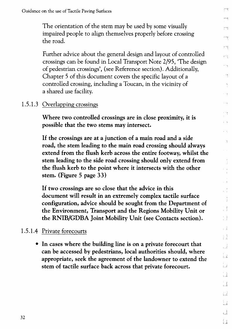
The orientation of the stem may be used by some visually impaired people to align themselves properly before crossing the road.
Further advice about the general design and layout of controlled crossings can be found in Local Transport Note 2/95, 'The design of pedestrian crossings', (see Reference section). Additionally, Chapter 5 of this document covers the specific layout of a controlled crossing, including a Toucan, in the vicinity of a shared use facility.
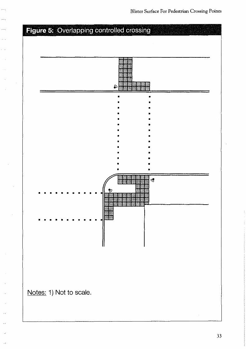
1.5 .1.3 Overlapping crossings
Where two controlled crossings are in close proximity, it is possible that the two stems may intersect.
If the crossings are at a junction of a main road and a side road, the stem leading to the main road crossing should always extend from the flush kerb across the entire footway, whilst the stem leading to the side road crossing should only extend from the flush kerb to the point where it intersects with the other stem. (Figure 5 page 33)
If two crossings are so close that the advice in this document will result in an extremely complex tactile surface configuration, advice should be sought from the Department of the Environment, Transport and the Regions Mobility Unit or the RNIB/GDBA Joint Mobility Unit (see Contacts section).
1.5.1.4 Private forecourts
32
• In cases where the building line is on a private forecourt that can be accessed by pedestrians, local authorities should, where appropriate, seek the agreement of the landowner to extend the stem of tactile surface back across that private forecourt.
Blister Surface For Pedestrian Crossing Points
Figure 5: Overlapping controlled crossing
• • • • • • • • • • • • • • • • • • • • • • • • • • • •
• • • • • • • • • • •
• • • • • • • • • • •
Notes: 1) Not to scale.
33

Guidance on the use of Tactile Paving Surfaces
1.5.1.5 Pedestrian refuges and other larger pedestrian islands
• Where pedestrian refuges form part of the crossing, the layout on the refuge will vary according to the space available and any other features which are located on it. Advice on this detail is contained in 1.5.3.
• It is important, however, that the blister surface is not installed on splitter islands where it is not generally intended that pedestrians should stop.
1.5.2 Uncontrolled crossings
At uncontrolled crossings the pedestrian does not have priority over vehicular traffic and must make a decision about whether it is safe to cross. For the purposes of this advice the following locations are described as uncontrolled crossings:
• side road crossings;
• busy crossovers (vehicle crossings);
• crossings away from junctions;
• kerb to kerb flat top road humps;
• signal controlled junctions without pedestrian phases (traffic lights), including those where studs indicating a pedestrian crossing place are provided.
It is recognised that installation of the tactile surface may not be possible at all locations in the short term. In prioritising sites for treatment, highway authorities should consult local groups of visually impaired people and rehabilitation officers (or mobility officers) (see Introduction- role of consultation).
1.5.2.1 Colour
34
• The blister surface should be buff or any colour (other than red) which provides a contrast with the surrounding footway surface.
_1;,
-2-

Blister Surface For Pedestrian Crossing Points
The contrast in colour will assist partially sighted people to identify the presence of tactile paving and hence be warned of the presence of a flush dropped kerb. In no circumstances should the red tactile surface be used at uncontrolled crossings. Red is strictly for controlled crossings only. To avoid confusion it is also advisable not to use any other red footway material in the vicinity of an uncontrolled crossing.
1.5.2.2 Generallayout
• The blister surface should be installed the full width of the flush dropped kerb. The depth of the surface will depend upon whether the flush dropped kerb is in the line of pedestrian travel (see 1.5.2.3 and 1.5.2.4). The purpose of the tactile surface is to compensate for the absence of a kerb upstand.
• The back edge of the tactile surface should be at right angles to the direction of crossing. This may not necessarily be parallel to the kerb. Some visually impaired people use the back edge of the tactile surface to align themselves correctly in the direction of crossing.
1.5.2.3 Inset (indented) uncontrolled crossings
• Where possible, crossings at side roads should be inset into the side road approximately one metre beyond the radius kerb. The tactile surface should be installed across the full length of the dropped kerb to a depth of 400mm (Figure 6 page 36). There are several advantages with indenting a dropped kerb into a side road:
• the raised radius kerb which remains provides positive guidance for drivers turning through the junction, so minimising the risk of vehicles overrunning the footway;
• a straight section of kerb, approximately lm long, can be provided immediately before the taper/dropper kerb, enabling visually impaired people to align themselves properly in order to cross the road;
35

Guidance on the use of Tactile Paving Surfaces
36
Figure 6: (Indented) uncontrolled crossing point at a side road
'Dropped kerb' road marking
Notes: 1) Not to scale.
Taper kerb(s)
Dropped kerb(s)
Taper kerb(s)
I
2) All dimensions in millimetres. ;_ --~
L --1

Blister Surface For Pedestrian Crossing Points
• if the flush dropped kerb is not in the direct line of travel, visually impaired pedestrians will not generally encounter it, preferring instead to cross on the first straight section of kerb. Even if they do encounter it they are likely to do so at an acute angle. In these circumstances a 400mm depth of tactile surface is all that is required. This layout ensures that the tactile surface can also be easily avoided by people with painful conditions such as arthritis.
• Dropping the radius section of the kerb will create difficulties for visually impaired people and wheelchair users and should be avoided. A flush radius kerb may lead visually impaired pedestrians into the path of traffic and may bring other vulnerable pedestrians, particularly wheelchair users, too close to passing traffic.
• Road markings to Diagram 1026.1 (Traffic Signs Regulations and General Directions ~ TSRGD) should be applied near inset uncontrolled crossing points to prevent them being blocked by parked cars.
It is recognised that it is not always possible or desirable to provide inset crossing points. The main limitations occur where:
• there is insufficient footway width in the side street to provide the manoeuvring space needed for a ramped approach to a dropped kerb;
• pedestrians crossing at such points would not be visible to approaching drivers;
• the dropped kerb is likely to be blocked by parked cars; or
• the inset crossing is too remote from the pedestrian desire line.
In these instances a crossing point in the line of travel will be necessary.
37

Guidance on the use of Tactile Paving Surfaces
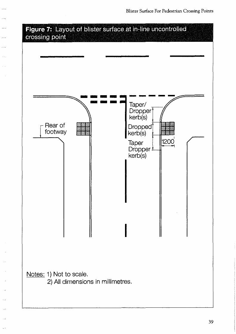
1.5.2.4 In-line uncontrolled crossings
• The tactile surface should be installed to a depth of 1200mm across the full width of the flush dropped kerb (Figure 7 page 39) The area of tactile surface needs to be sufficient to provide the necessary warning to a visually impaired pedestrian proceeding at a normal walking pace. At no point across the flush dropped kerb should the depth of the surface be less than 1200mm.
1.5.2.5 Acute angled junctions
• The basic rule is that dropped kerbs on either side of a road should be directly opposite each other to minimise the crossing distance (Figure 8 page 40). On acute angled junctions this will, of course, result in a significant deviation to one of the dropped kerbs. However, it is considered that this arrangement meets the needs of all concerned: visually impaired people have a straightforward tactile surface layout; and wheelchair users benefit from a smaller area of tactile surface and a shorter crossing distance.
1.5.2.6 Crossing away from a junction
38
• Visually impaired people will not generally use a crossing away from a junction and would prefer, where possible, to be directed to a controlled crossing by the appropriate tactile surface. At crossings away from junctions, therefore, a flush dropped kerb should be provided and the tactile surface should be installed to a depth of 800mm (Figure 9 page 41). In most cases a clear pathway is then provided around the surface for people with painful conditions such as arthritis. Before installing a flush dropped kerb and tactile surface at an uncontrolled crossing point away from a junction, it is important to consider whether the particular site is the most suitable for vulnerable road users, particularly visually impaired people and wheelchair users. If there is a controlled crossing in close proximity to the site, then it may be preferable not to provide a crossing away from a junction with a flush dropped kerb and tactile surface. Local consultation will establish whether that approach is acceptable. However, facilities for both wheelchair users and visually impaired people should be provided at the controlled crossing.
Blister Surface For Pedestrian Crossing Points
Figure 7: Layout of blister surface at in-line uncontrolled crossing point
Rear of footway
Notes: 1) Not to scale.
---
I
Taper/ Dropper kerb(s)
Dropped kerb(s)
Taper Dropper kerb(s}
2) All dimensions in millimetres.
39

Guidance on the use of Tactile Paving Surfaces
40
Figure 8: Layout of blister surface at (indented) uncontrolled crossing at acute angled junction
-
7 !W--- Crossing places must be directly opposite
/
. o<:t,.~
.,;:{o <::)"<;
Notes: 1) Not to scale. 2) All dimensions in millimetres.
, __ j_

Blister Surface For Pedestrian Crossing Points
Figure 9: Uncontrolled crossing away from junction
Rear of footway
800
800
[ Rear of footway
Notes: 1) Not to scale. 2) All dimensions in millimetres. 3) Width of tactile will depend on the width of the crossing.
41

Guidance on the use of Tactile Paving Surfaces
1.5.2. 7 Pedestrian refuges
• Where pedestrian refuges form part of the crossing, the layout on the refuge will vary according to the width of the refuge and any other features which are located on it. Advice on this detail is contained in 1.5.3.
• If the refuge is not intended as an area for pedestrians to wait, as in the case of splitter islands, then the tactile surface should not be installed.
1.5.3 Pedestrian refuges and other larger pedestrian islands
The layouts described in this section apply equally to controlled and uncontrolled crossings. As previously indicated, however, the colour of the material will depend on whether the crossing is controlled or uncontrolled (see 1.5.1 and 1.5.2 for definitions). Where the refuges/islands are in conservation areas some relaxation of the colour requirements may apply (see 1.5.6).
1.5.3.1 Standard pedestrian refuge
• Where the refuge is less than 2m depth - the surface should be laid across the full width, set back behind the kerb or 150mm from the edge of the carriageway (where the refuge is at carriageway level) on both sides (Figure 10 page 43 ).
• Where the refuge is two metres or more in depth, two rows of the tactile surface 800mm deep should be provided. Each row should be set back behind the kerb or 150mm from the edge of the carriageway (where the refuge is at carriageway level) on both sides (Figure 11 page 43 ).
1.5.3.2 Staggered pedestrian island
42
• Where guard rails are provided on islands at staggered crossings, the tactile surface needs to be installed to a depth of 800mm only, behind the kerb or set back 150mm from the edge of the carriageway on both sides (Figure 12 page 44 ).
'·-- ~;

Blister Surface For Pedestrian Crossing Points
The guard rails can be used by visually impaired people to guide them to the crossing point.
• It is important that the signal poles with push button boxes are installed in line with the guard railing and close to the edge of the blister paving to enable visually impaired people to locate easily the push buttons.
Other furniture should be positioned such that it does not create an obstacle for pedestrians.
Figure 10: Layout of blister surface on standard refuge less than 2m wide
150mm .-------~~-r--------------r-~------+or
Less than
2000mm
00 0 ~00 0 0 0 0 0 0 0 0 0 0 0 0" 0 0 0 00 0 0 0 0 0 -------=~--+ ...................................................... .,.. kerb wl'dth 0 0 0 0 0 0 0 0 0 0 0 0 0 0 0 0 0 0 0 0 0 0 0 00 0 0 .. 0 0 oooooooooooooooooooooooooooooo
ooooooooooooooooooooooooooooo 00000000000000000000000000000
00000000000000000000000000000 00000000000000000000000000000 00000000000000000000000000000
oooooooooooooooooooooooooooooo
Notes: 1) Not to scale.
000000 ooooooooooooooooooooooo 000000 00000000000000000000000
000000 00000000000000000000000
000000 00000000000000000000000
oooooooooooooooooooooooooooooo 000000000000000000000000000000
ooooooooooooooooooooooooooooe ooooooooooooooooocoooooooooo
Figure 11: Layout of blister surface on standard refuge greater than 2m wide
Greater than
2000mm
Notes: 1) Not to scale.
43

Guidance on the use of Tactile Paving Surfaces
Fiaure 12: Lavout of blister surface on a staaaered pedestrian island
.. • • • • • • • • • • • • • • • • Push button • • • • • • • •
• • • 150mm • • • • • • • • • • • • • • • • •
Notes: 1) Not to scale. 2) Traffic signals omitted for clarity.
44
;_ j:
"---"'

Blister Surface For Pedestrian Crossing Points
1.5.3.3 Triangular pedestrian islands
• The blister surface should be installed across the full width of each dropped kerb to a depth of 800mm, set back behind the kerb or 150mm from the carriageway on all sides (Figure 13 page 46).
• Pedestrians should be kept away from the comers of the triangular island by the use of a kerbing edge surface or guard railing (Figure 13 page 46).
It is important too that the needs of wheelchair users are considered in the design of triangular islands. A level area should be provided in the centre of the island to allow wheelchair users to move between crossings.
1.5.4 Vehicle crossovers and vehicle accesses
1.5.4.1 Generallayout
• At all vehicle crossovers a minimum 25mm upstand should be provided between the carriageway and the vehicle crossover. There should be no upstand where the footway crosses the vehicle crossover (Figure 14 page 47). Providing the 25mm upstand should ensure that visually impaired people do not venture into the carriageway as they make their way across. Ensuring that there is no upstand across the vehicle crossover should ensure that wheelchair users have unimpeded access along the footway.
• Where the vehicle crossover surface is being replaced with another surface, it is helpful if the replacement surface provides a contrast in colour and tone. For example, replacing light coloured paving slabs with darker block paviors. This will be helpful to partially sighted people who are regular users of the area to distinguish between the crossover and the adjacent footway.
45

Guidance on the use of Tactile Paving Surfaces
Fiaure 13: Location of blister surface on a trianaular pedestrian island
• • llluminous ballard • • • • • $
• • • • • • • • • • Guardrail Angled to or the post Kerbing edge
/
150mm • • • • • • • " " •
Notes: 1) Not to scale. 2) Traffic signals omitted for clarity.
46
$ $
• • $
$
• • • •

Blister Surface For Pedestrian Crossing Points
1.5.4.2 Vehicle crossovers with high traffic flows
• Where the traffic flow is sufficiently high, a vehicle crossover or vehicle access should be treated as an uncontrolled crossing at a side road and the tactile surface should be installed appropriately (See 1.5.2.3 ). Local authorities will have to exercise their own judgement, in consultation with interested parties, when assessing traffic flows, but vehicle crossovers and vehicle access to the following facilities are examples where the tactile surface would be justified:
• petrol station or commercial garage;
• shopping parade, supermarket, etc.;
• medical centre or hospital;
• public car park or pub car park.
Figure 14: Vehicle crossovers and vehicle accesses
Footway
-Kerb
Unimpeded access for wheelchair users.
No upstand
. / Crossover , \ --Carriageway - Upstand > 25mm
I. Vehicle crossover
:+Upstand > 25mm
j Carriageway
Notes: 1) Not to scale.
47

Guidance on the use of Tactile Paving Surfaces
1.5.4.3 Vehicle crossovers to residential property
• The tactile surface should not generally be applied on vehicle crossovers to residential property. The blister surface will only be necessary where there is a high volume of traffic, for example, at the entrance to a block of flats (see 1.5.4.2).
1.5.5 Traffic calming
1.5.5.1 Generallayout
• Where the carriageway has been raised to the level of the footway the tactile surface should be installed on the footway. The treatment will be the same as for an uncontrolled or controlled crossing depending on the facilities to be provided on the raised area. Where an extensive area of the carriageway has been raised then it will not be appropriate to install the tactile surface along the full length. In those circumstances the tactile surface should be limited to the 'crossing' area (Figure 15 page 49), and the remaining raised carriageway either side of the tactile surface should maintain a level difference with the footway of at least 25mm high or have a continuous physical barrier, for example, planters, railings.
1.5.5.2 Side road entry treatments
• Where side road entry treatments provide an uncontrolled crossing facility they should be treated as for an in,line uncontrolled crossing (Figure 16 page 49).
1.5.5.3 Entire junction treatments
48
• Where the carriageway has been raised to the level of the footway around an entire junction, it is essential that visually impaired pedestrians are kept away from the radius by the use of continuous physical barriers, for example, guard railings (Figure 17 page 50).
' _f:_

Blister Surface For Pedestrian Crossing Points
Figure 15: Layout of blister surface at an uncontrolled crossing on a kerb to kerb flat top road hump
Flush section
Guardrailing or kerb upstand
1) Not to scale. 2) Illustration is an uncontrolled crossing.
Notes: 1) Not to scale. 2) Layout shown is an uncontrolled crossing.
49

Guidance on the use of Tactile Paving Surfaces
Figure 17: Layout of blister surface at a junction where the entire carriageway has been raised to the level of the footway
-Guardrailing
I
Notes: 1) Not to scale. 2) Crossings shown are uncontrolled.
50
, _____ _£

Blister Surface For Pedestrian Crossing Points
1.5.6 Conservation areas
1.5.6.1 Colour
• Where the blister surface is provided at crossing points in conservation areas or in the vicinity of a listed building, some relaxation of the colour requirements may be acceptable. In these limited circumstances only, the tactile surface may be provided in a colour which is in keeping with the surrounding material. This relaxation does not extend to the use of red at uncontrolled crossing points. Before any decision is taken by the local authority, discussions should take place with local groups of visually impaired people and rehabilitation (or mobility) officers and the local conservation officer. Further advice is given in "Traffic Measures in Historic Towns", which is produced by the Civic Trust and the English Historic Towns Forum (see Reference document section).
1.5. 7 Inspection covers
1.5. 7.1 Blister surface inlays
• Local authorities should encourage utilities, where possible, to provide covers which can be converted to take a blister surface inlay. The layout of blister surfaces can be disrupted by inspection covers, creating layouts which are confusing for visually impaired pedestrians and are generally unsightly (Figure 18 page 52).
51

Guidance on the use of Tactile Paving Surfaces
Figure 18: Inspection cover that has been inlaid with blister surface so as not to disrupt the desired layout
Carriageway [Kerb
? 0 0 0 0 0 0 0 0 0 0 0 0 0 0 0 0 0
o o o o o o o o o o o o o o a o a
Notes: 1) Not to scale. 2) Illustration is an uncontrolled crossing.
1.5.8 Partially pedestrianised areas
52
Avoid creating hazards for visually impaired people. For example, ensuring an upstand is retained (no less than 25mm high) at the edge of long continuous sections of footways in partially pedestrianised areas and using different surface colours to differentiate between the footway and carriageway should provide the essential warning required by visually impaired pedestrians. The kerb at designated crossing points should, however, be flush and the appropriate blister surface layout should be provided. This avoids extensive use of the blister surface which would add to the costs of such schemes and would make the area confusing and, therefore, potentially unsafe for visually impaired people.

CHAPTER 2
Corduroy Hazard Warning Surface
This chapter should be read in conjunction with the advice in the Introduction.
2.1 Purpose
• The purpose of the corduroy surface is to warn visually impaired people of the presence of specific hazards: steps, level crossings or the approach to on~street light rapid transit (LRT) platforms. It is also used where a footway joins a shared route (see Chapter 5). It conveys the message 'hazard, proceed with caution'.
2.2 Definition
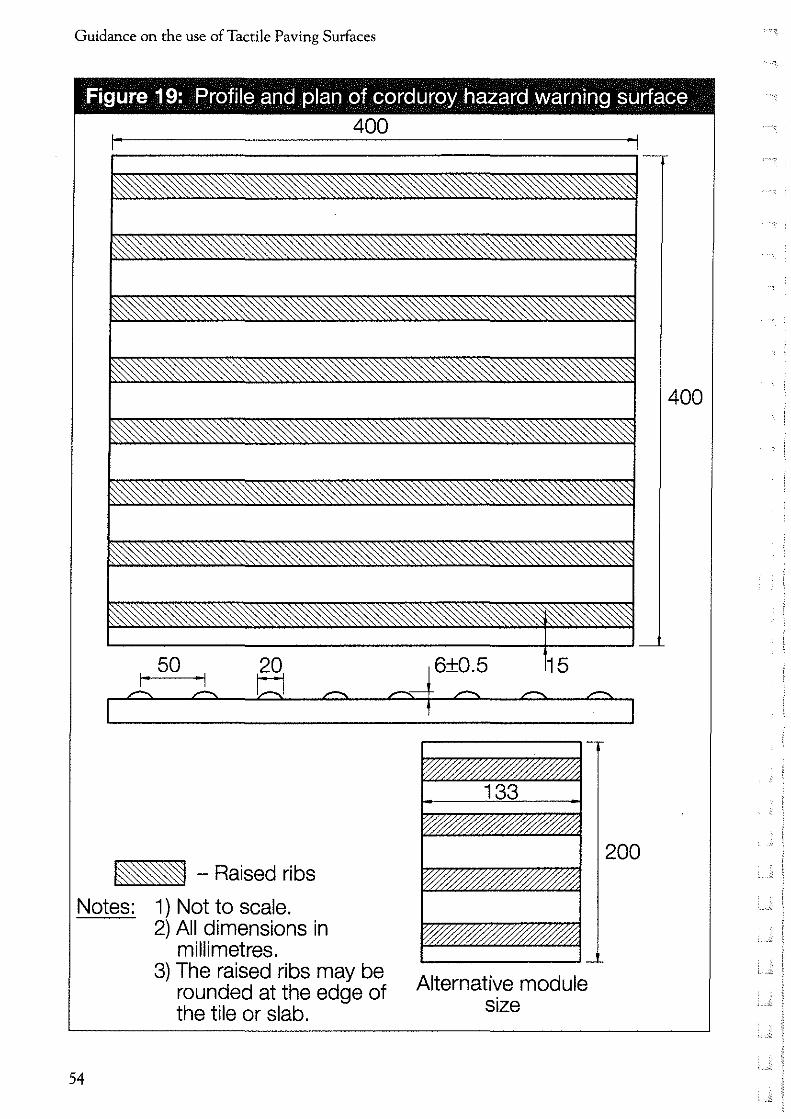
• The profile of the corduroy surface comprises rounded bars running transversely across the direction of pedestrian travel. The bars are 6mm (± 0.5mm) high, 20mm wide and spaced 50mm from the centre of one bar to the centre of the next (Figure 19 page 54).
It is recommended that the surface be in a contrasting colour to the surrounding area so as to assist partially sighted people. It should not be red which is restricted to the blister surface at controlled crossings (see 1.5.1).
• The surface can be provided in any material suitable for pedestrian routes.
53
Guidance on the use of Tactile Paving Surfaces
Figure 19: Profile and plan of corduroy hazard warning surface
400
J:so ::l 20 w
~ - Raised ribs
Notes: 1) Not to scale.
54
2) All dimensions in millimetres.
3) The raised ribs may be rounded at the edge of the tile or slab.
Alternative module size
200
400

Corduroy Hazard Warning Surface
2.3 Application
• The corduroy surface can be used for any situation (except at pedestrian crossing points - see Chapter 1) where visually impaired people need to be warned of a hazard and advised to proceed with caution, for example:
• the top and bottom of steps;
• the foot of a ramp to an on,street light rapid transit (LRT) platform, but not at any other ramps;
• a level crossing;
• where people could inadvertently walk directly on to a platform at a railway station; and
• where a footway/footpath joins a shared route (see Chapter 5 ).
The surface must not be used to warn of obstacles, for example, cycle stands, where people should be advised not to proceed. Cycle stands come in a range of designs, but those with two vertical uprights can be made less of a hazard if they are designed with a tapping rail between the two uprights at a height of 150,200mm above the ground.
The surface is not recommended on raised bus stops.
2.4 Maintenance
2.4.1 Condition of surface
It is important to monitor the condition of the tactile surface and to plan for replacement as part of maintenance programmes. The profile of the tactile surface, as described in 2.2, is crucial to its effectiveness as a warning to visually impaired people.
At 5.5mm (the lower tolerance) the surface will still be effective. If the bars fall below that height the effectiveness of the surface will be reduced and will ultimately be undetectable.
55

Guidance on the use of Tactile Paving Surfaces
2.4.2 New Roads and Street Works Act 1991
The New Roads and Street Works Act 1991 requires the replacement of the corduroy surface when it is removed or disturbed in the course of opening the footway by the party disturbing the surface. It is essential that any reinstatement of the surface conforms with the advice in this document.
2.5 Layout
2.5.1 Generallayout
• The surface should be laid so that the bars run transversely across the direction of pedestrian travel.
2.5.2 Steps (Figure 20 page 57)
56
• The corduroy surface should extend across the full width of the stairs at both the top and bottom of the flight.
• Where possible, the surface should start 400mm from the first nosing. If the surface is installed closer to the steps, people may not have enough time to adjust their walking speed.
• If the steps are in the direct line of pedestrian travel the surface should be laid to a depth of 800mm.
• If a pedestrian would have to make a conscious tum to encounter them, then a depth of 400mm is acceptable.
Since it is generally intended as an additional warning, there is no need to install the surface to a depth of more than 800mm.
• The surface should extend at least 400mm beyond the width of the steps on either side. This allows for people approaching the steps at an angle. However, the surface should not extend across any adjacent facilities, for example a ramp or lift.

Corduroy Hazard Warning Surface
Figure 20: Layout of corduroy hazard warning surface at the top & bottom of a flight of stairs
400
400
800
Notes: 1) Not to scale. 2) All dimensions in millimetres. 3) Depth may be reduced to 400mm where a pedestrian
would have to make a conscious turn to encounter the flight of stairs.
57

Guidance on the use of Tactile Paving Surfaces
• A continuous handrail acting as a guide across intermediate landings will inform the user that the series of steps continues, and so obviates the need for the surface to be installed. This avoids the use of excessive amounts of the surface. However, the surface should be installed if the staircase can be accessed via a landing.
• Where ramped access is provided immediately adjacent to steps then care should be taken to ensure that the access for wheelchair users is unimpeded (Figure 21A&B page 60).
2.5.3 Ramps to light rapid transit (LRT) platforms (Figure 22 page 61).
• The surface should be installed across the full width of the ramp at the bottom only.
• The corduroy surface should be laid 400mm from the bottom of the ramp and to a depth of 800mm.
2.5.4 Level crossings (Figure 23 page 62).
58
• The corduroy surface should extend across the full width of the footway, or for 1200mm if there is no footway.
• The corduroy surface should start 400mm from the barrier or from the projected line of the barrier on the open side.
If the corduroy surface is installed closer, people may not have enough time to adjust their walking speed.
• At level crossings with barriers on both sides, the corduroy surface should be laid to a depth of 400mm.
• At level crossings with barriers on one side only, the corduroy surface should be installed to a depth of 400mm on the side with the barrier and 800mm on the side without a barrier.
• At level crossings with no barriers, the surface should be installed to a depth of 800mm on both sides.

Corduroy Hazard Warning Surface
The additional depth of tactile in the latter two cases is to ensure that visually impaired people have sufficient underfoot warning where there is no barrier in place to halt their progress.
2.5.5 Entrance to platform area in an unprotected rail station
• The corduroy surface should be laid across the full width of the pedestrian entrance.
• The corduroy surface should be installed to a depth of 800mm. In some railway stations it is possible for visually impaired people to walk unknowingly onto a platform area from the street.
2.5.6 Shared facilities
• The corduroy surface should also be used where a footpath or footway joins a segregated shared route for cyclist's and pedestrians on the cyclist's side (see Chapter 5, section 5.5.2.1 ).
59

Guidance on the use of Tactile Paving Surfaces
Figure 21: Layout of corduroy hazard warning surface where ramp access is immediately adjacent to steps
®
® -
Notes: 1) Not to scale. 2) All dimensions in millimetres.
60

Corduroy Hazard Warning Surface
Figure 22: Layout of corduroy hazard warning surface at ramps to light rapid transit platform on street
Edge of platform
I. Rails.!
Notes: 1) Not to scale. 2) All dimensions in millimetres.
On-street platform edge warning surface
Ramp to raised platform
61

Guidance on the use of Tactile Paving Surfaces
Fiaure 23: Lavout of cordurov hazard warnina surface at level crossing
400
• • 0
Ef39_J_E;CTE_Q _ LINE
Notes: 1) Not to scale. 2) All dimensions in millimetres.
62
• • 0
( --'"

CHAPTER 3
Platform Edge (Off ... Street)
Warning Surface This chapter should be read in conjunction with the advice in the Introduction.
3.1 Purpose
• The purpose of this surface is to warn visually impaired people of the edge of all off,street railway platforms.
3.2 Definition
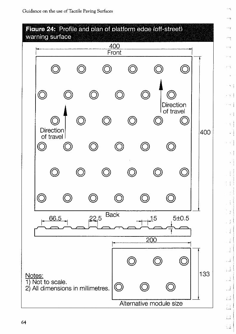
• The profile of the platform edge (offstreet) warning surface consists of offset rows of flat,topped domes 5mm (±0.5mm) high, spaced 66.5mm apart from the centre of one dome to the centre of the next (Figure 24 page 64 ). The surface is different to the blister surface used to warn of the absence of a kerb upstand at pedestrian crossing points (see Chapter 1 ).
The surface can be any colour other than red, but should provide a good contrast with the surrounding area to assist partially sighted people.
3.3 Application
The platform edge warning surface is recommended for use at all off,street rail platforms including:
• heavy rail platforms; • off,street light rapid transit (LRT)
platforms; and • underground platforms.
63
Guidance on the use of Tactile Paving Sutfaces
Fiaure 24: Profile and olan of olatform edae (off-street) warning surface
400 ,. Front
© ©
© © © © © © Direction of travel
.,
© © © © © © Direction of travel
© © © © © ©
© © © © © ©
© © © © © ©
200 ~------------~~-
Notes: 1) Not to scale. ~ 2) All dimensions in millimetres. Q
~~-------~~~-Alternative module size
64
400
133

Platform Edge (Off-Street) Warning Sutface
It should not be used at on-street LRT platforms where the lozenge shaped platform edge warning surface should be used (see Chapter 4 ).
3.4 Maintenance
3.4.1 Condition of surface
It is important to monitor the condition of the tactile surface and to plan for replacement as part of maintenance programmes. The profile of the tactile surface, as described in 3.2, is crucial to its effectiveness as a warning to visually impaired people.
At 4.5mm (the lower tolerance) the surface will still be effective. If the flat topped domes fall below that height the effectiveness of the surface will be reduced and it will ultimately be undetectable.
3.5 Layout
The platform edge (off-street) warning surface should be laid immediately behind the platform edge coping stone (Figure 25 page 66).
In most cases this will be between 600mm and 700mm back from the platform edge, but in some circumstances this may be as little as 500mm. It should never be less than that because people may not have enough time to stop walking once they have detected the tactile surface.
The surface should be installed to a depth of 400mm along the entire length of the platform.
This depth has been found to be sufficient in this environment.
The surface should never be laid at right angles to the platform edge to mark the end of the platform.
Where the platform ends or slopes down to the track, the surface should stop at this point and some other method employed to prevent people walking beyond the designated passenger area.
The edge of the platform should still be marked with a white line.
This will assist partially sighted people.
65

Guidance on the use of Tactile Paving Surfaces
Figure 25: Layout of platform edge (off-street) warning surface
Coping stone
White line~ //Platform edge
.. 500-700 /
-· ..... 0 0 0 0 0 0 0 0 0 0 0 0 0 0 g 0 0 0 0 0 0 0 0 0 0 0 0 G 0 0 0 • 0 0 0 0 0 II 0
I 0 0 0 0 0 0 0 • 0 0 0 0 0 II 0 0 0 0 0 0 0 0 0 0 0 0 0 0 0 0 0 • 0 0 0 0 0 0 0 • 0 •• ' 0 II 0 o o 0 Iii' 0 0 0 Cl 0 0 0 0 0 0 0 0 0 0 0 0 • 0 0 0 0 0 0 0 0 0 0 0 0 ....... 0 • • 0
) • 0 0 0 0 0 0 0 0 0 0 0 0 0 0 0 0 0 0 0 0 0 0 0 0 • 0 0 0 0 0 • 0 0 0 •• 0 0 • 0 0.' 400 0 0 0 0 0 000000 0 • 0 0 0 0 0 0 0 0 •• 0 0 0 0 0 0 • • 0 • 0 0 0 ..... , 0 0 0 0
L.,.__,' 0. 0 0 0 0 0 0 0 0 0 0 0 0 0 0 0 0 0 0 0 0 0 0 0 • 0 0 0 0 0 0 0 • 0 0 0 0 0 0 0 • 0 '
Notes: I) Not to scale. 2) All dimensions in millimetres.
66
CHAPTER 4
Platform Edge (On--Street)
Warning Surface
This chapter should be read in conjunction with the advice in the Introduction.
4.1 Purpose
• The purpose of the platform edge (on,street) warning surface is to warn visually impaired people that they are approaching the edge of an on,street light rapid transit (LRT) platform.
With the introduction of on-street LRT platforms, it is now possible for pedestrians to encounter a platform whilst walking along a footway.
4.2 Definition
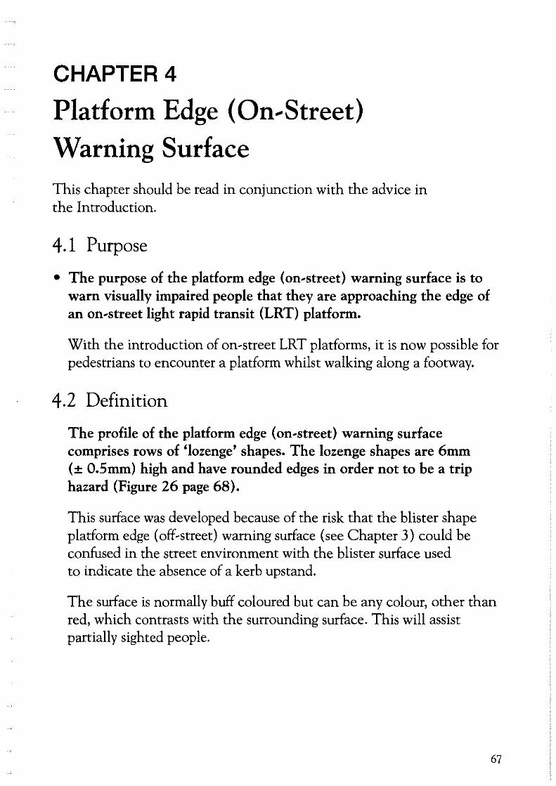
The profile of the platform edge (on,street) warning surface comprises rows of 'lozenge' shapes. The lozenge shapes are 6mm (± 0.5mm) high and have rounded edges in order not to be a trip hazard (Figure 26 page 68).
This surface was developed because of the risk that the blister shape platform edge (off-street) warning surface (see Chapter 3) could be confused in the street environment with the blister surface used to indicate the absence of a kerb upstand.
The surface is normally buff coloured but can be any colour, other than red, which contrasts with the surrounding surface. This will assist partially sighted people.
67
Guidance on the use of Tactile Paving Surfaces
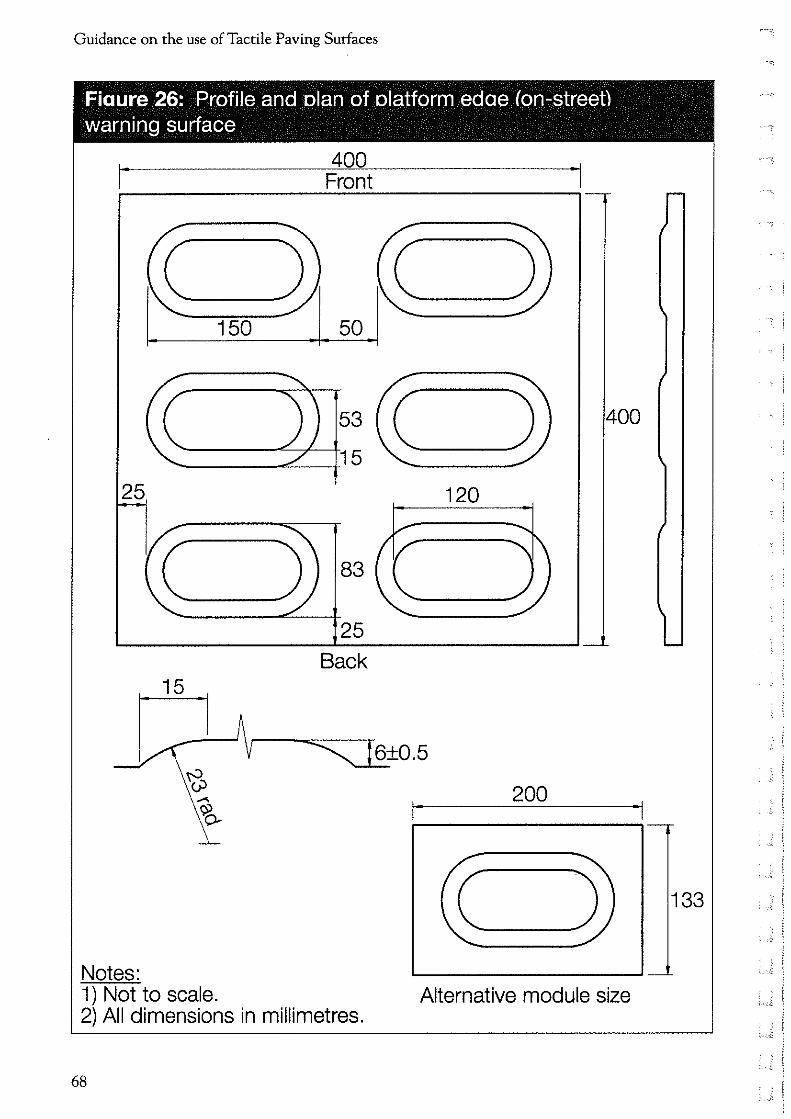
Fiaure 26: Profile and olan of olatform edae (on-street) warning surface
400 I. Front .I
~~~150
400
120
83
25 Back
200
Notes: 1) Not to scale. Alternative module size 2) All dimensions in millimetres.
68
133
'--""

Platform Edge (On-Street) Warning Sutface
4.3 Application
• The lozenge surface is recommended for use at all on,street LRT platform edges. It should not be used at off,street platforms where the flat topped dome platform edge (off,street) warning surface should be used (see Chapter 3).
• The surface is not recommended for use at raised bus stops.
4.4 Maintenance
4.4.1 Condition of surface
It is important to monitor the condition of the tactile surface and to plan for replacement as part of maintenance programmes. The profile of the tactile surface, as described in 4.2, is crucial to its effectiveness as a warning to visually impaired people.
At 5.5mm (the lower tolerance) the surface will still be effective. If lozenges fall below that height the effectiveness of the surface will be reduced and it will ultimately be undetectable.
4.4.2 New Roads and Street Works Act 1991
The New Roads and Street Works Act 1991 requires the replacement of the platform edge (on street) warning surface when it is removed or disturbed in the course of opening the footway by the party disturbing the surface. It is essential that any reinstatement of the surface conforms with the advice in this document.
69

Guidance on the use of Tactile Paving Surfaces
4.5 Layout
The lozenge surface should be laid immediately behind the platform coping stone (Figure 27 below). This should not be closer than 500mm from the platform edge, because people may not have enough time to stop walking once they have detected the tactile surface.
The surface should be installed to a depth of 400mm along the entire length of the platform, and should extend down any approach ramps. This depth has been found to be sufficient in this environment.
The corduroy warning surface should be used to indicate ramped approaches to on-street platforms (see Chapter 2).
Figure 27: Layout of platform edge (on street) warning surface
Coping stone
White ge line~ //Platform ed • /
500-700 / d)g gg gg gg gg gg gg gg Qtb d'>lbdl lbd> lbd> lbd>lbd> gg gg ibd>Q QQl lbd> Ql lbdlib dlQl QQl QlQ QQl gg QlQl QlQl lbd> Ql lbd> 16
Notes: 1) Not to scale. 2) All dimensions in millimetres.
70 , ___ ;;

CHAPTER 5
Segregated Shared Cycle Track/Footway
Surface and Central Delineator Strip
This chapter should be read in conjunction with the advice in the Introduction.
Segregation of pedestrians and cyclists by providing for cyclists on the carriageway or the segregation of the footway and cycle track by a level difference, should be the aim of highway authorities, particularly in new developments. This will not only assist visually impaired people, but will also be helpful to other vulnerable pedestrians such as those with impaired hearing and those with walking difficulties. Where it is not possible to achieve segregation by any of those means the advice in this chapter should be followed.
5.1 Purpose
• The purpose of the tactile surface used in conjunction with a segregated shared cycle track/footway is to advise visually impaired people of the correct side to enter.
• The purpose of the central delineator strip is to help visually impaired pedestrians keep to the pedestrian side.
The central delineator is normally installed along the length of the route dividing the pedestrian from the cyclist side. It is essential that the profile of the delineator is to the precise specification set out in 5.2 and in Figure 28.
71

Guidance on the use of Tactile Paving Surfaces
Figure 28: Profile and plan of segregated shared cycle track/footway surface and central delineator strip
"Ladder" pattern on the footway or footpath
"Tramline" pattern on the cycle track
j I
Raised nll i20mm line -1111 drainage gap
12 min L / '----20 max e::~~======~=~·tD-6 max
35 30 H H
150 Cross section of raised line 400
30 70 5+0.5~1 I I
Cross section of tramline
,-
133[[]]
2400
Notes: 1) Not to scale. 2) All dimensions in millimetres.
1 2oo 1 Alternative module size
72

Segregated Shared Cycle Track/Footway Surface and Central Delineator Strip
5.2 Definition
• The profile of the tactile surface comprises a series of raised, flat~ topped bars, each 5mm (±0.5mm) high, 30mm wide, and spaced 70mm apart (Figure 28 page 72).
• The central delineator strip is 12~20mm high, 150mm wide with sloping sides and a flat top of 50mm (Figure 28 page 72). The material should have a white finish. This is prescribed in the Traffic Signs Regulations and General Directions - TSRGD (Diagram 1049.1) with a construction tolerance of ±6mm for any vertical upstand below the trapezoidal profile (see Figure 33 page 83 ). Recent research has confirmed the importance of ensuring the profile conforms to TSRGD to be fully effective and has highlighted the increased value of a 20mm profile to visually impaired pedestrians (Table 1 ).
Table 1
12mm 20mm
% of visually impaired people able to keep to one side of the 78 96 delineator strip
% of cyclists rating profile as "unsafe" when cycling 5 7 alongside the delineator strip
5.3 Application
• The tactile surface and central delineator strip should be used on any segregated shared route where the designated pedestrian side is not physically separated from the designated cyclist side, for example by a difference in level.
73

Guidance on the use of Tactile Paving Surfaces
5.4 Maintenance
5.4.1 Condition of the surface
It is important to monitor the condition of the tactile surface and to plan for replacement as part of maintenance programmes. The profile of the tactile surface, as described in 5.2, is crucial to its effectiveness as a warning to visually impaired people.
At 4.5mm (the lower tolerance) the surface will still be performing. If the bars fall below that height the detectability of the surface will be reduced and will ultimately be undetectable.
For the delineator to be detected reliably it should not be less than 12mm while retaining the precise profile shown in Figure 28.
5.4.2 New Roads and Street Works Act
The New Roads and Street Works Act 1991 requires the replacement of the surface when it is removed or disturbed in the course of opening the footway. It is essential that any reinstatement of the surface conforms with the advice in this document.
5.5 Layout
5.5.1 Generallayout
74
The tactile surface should be laid at the beginning and end of the shared segregated route, at regular intervals along the route and at any junctions with other pedestrian or cyclist routes. This lets people know they are entering or leaving the route.
In general, the surface should extend across the full width of the footway and cycle track and should extend to a depth of 2400mm. For the repeater strips, however, only 800mm depth of surface is required.
On the pedestrian side, the surface should be installed with the bars running transversely across the direction of travel (Figure 29 page 75).
-"

Segregated Shared Cycle Track/Footway Surface and Central Delineator Strip
Figure 29: Layout of segregated shared cycle track/footway surface and central delineator strip
Notes: 1) Not to scale.
Raised central delineator strip
75

Guidance on the use of Tactile Paving Surfaces
On the cyclist side, the surface should be laid with the bars running in the direction of travel (Figure 29 page 75). This arrangement was chosen because it was felt the rumble effect created by the transverse pattern would deter cyclists from entering on the pedestrian side.
The central delineator strip should run the entire length of the route, creating a "kerb" between the designated pedestrian side and the designated cyclist side. A painted white line is not adequate for this purpose as it will not be detected by visually impaired pedestrians.
A cycle symbol marking should be provided on the appropriate side at all entry/exit points and any junctions with footways or other shared routes. This will inform cyclists and sighted pedestrians of the designated sides.
The use of colour and texture can also assist blind and partially sighted people. Using different coloured surfaces and different materials, eg. bitumen and concrete, on the different sides of the route can provide a useful additional cue.
5.5.2 Junctions
5.5.2.1 Junction where a footway joins a shared route
76
On the pedestrian side:
• The tactile surface should be installed for 2400mm on both the pedestrian and cyclist sides on either side of the junction (See Figure 30A page 78).
• The central delineator strip should continue across the junction. This will act as a guide to keep visually impaired people on the pedestrian side.
' £

Segregated Shared Cycle Track/Footway Surface and Central Delineator Strip
On the cyclist side:
• The tactile surface should be installed on both the pedestrian and cyclist sides for 2400mm on both sides of the junction (see Figure 30B page 78).
• The central delineator strip should not continue across the junction.
• In addition, to warn visually impaired people that they are stepping on to the cyclist side, the corduroy surface (see Chapter 2) should be installed across the footway/footpath to a depth of 800mm where it joins the shared route.
5.5.2.2 Junction where a cycle track joins a shared route
On the cyclist side:
• It is not necessary to install the tactile surface.
• The central delineator should continue across the junction (Figure 31A page 79). This is because there is no break in the pedestrian side and pedestrians do not need to be informed that there is a junction with a cycle track.
On the pedestrian side:
• The tactile surface should be installed for a depth of 2400mm on either side of the junction.
• The central delineator should not continue across the junction (Figure 31B page 79).
77

Guidance on the use of Tactile Paving Sutfaces
Figure 30: Layout at a junction where a footway or footpath joins a shared route on the pedestrian side and on the cyclist side
Pedestrian path
® Corduroy
path
Tactile area
Notes: 1) Not to scale.
Footpath
Footpath
2) All dimensions in millimetres.
78
lsoo ___i
Central delineator
Central delineator
'-- ,.,

Segregated Shared Cycle Track/Footway Surface and Central Delineator Strip
Figure 31: Layout at a junction where a cycle track joins a shared route on the cyclist side and on the pedestrian side
Cycle track
~ Pedestrian path
® "Start" and "End" tactile area
Pedestrian path
2400
Notes: 1) Not to scale.
Cycle track
A
Cycle track
A
2) All dimensions in millimetres.
Central delineator
2400
Central delineator
79

Guidance on the use of Tactile Paving Surfaces
5.5.2.3 Junction where a shared route joins another shared route
• The tactile surface should be installed for 2400mm on both the pedestrian and cyclist sides of both routes and on either side of the junction (Figure 32 page 82).
• The central delineator should not continue, in either direction, through the junction (Figure 32 page 82).
5.5.2.4 Vehicular access route across a shared routean uncontrolled crossing
• Where a carriageway, such as a side road, crosses the shared route, tactile surfaces should be provided, as in Figure 33 page 83, to indicate the start/end of the route. At the flush dropped kerb it will be necessary to provide the blister surface to a depth of 1200mm, and this should be laid across the full width of the crossing point. The tactile surface should be located about 1200mm from the blister surface.
If the tactile surface advising of the start/end of the segregated path is only installed on the cyclists' side, visually impaired pedestrians will not be aware they are about to leave the footway. The tactile surface needs to be installed on the cyclists' side to ensure that people re-enter the route on the pedestrian side once they have crossed the road.
5.5.2.5 Vehicular access route across a shared routea controlled crossing
80
• A similar approach is also required where a controlled crossing is provided at the start/end of the route. The detail is shown in Figure 34 page 84.
To avoid conflict between cyclists and pedestrians it will be helpful if the "L" leads down from the end of the pedestrian side of the shared route. In some cases this may require the installation of an additional pedestrian push button box adjacent to the pedestrian path. At Toucan crossings two pedestrian push button boxes will always be required.
'-Oi
Segregated Shared Cycle Track/Footway Surface and Central Delineator Strip
5.5.2.6 Controlled crossings along a shared route
• Where a controlled crossing is situated on a shared route the blister tactile should be installed to indicate the presence of a dropped kerb (see section 1.4.1 ). The stem should extend back from the flush dropped kerb to the rear of the pedestrian path (Figure 35 (A) and (B) page 85). The cycle track/footway surface should also be installed to a depth of 2400mm at the start/end of the shared route.
• The delineator strip should not continue across the route only where the cyclists' side is closest to the carriageway, or where the crossing is a Toucan.
81

Guidance on the use of Tactile Paving Surfaces
82
Figure 32: Layout at a junction where a shared route joins another shared route
Pedestrian path
Notes: 1) Not to scale.
Cycle track 1
A Pedestrian path
2) All dimensions in millimetres.
2400 Central delineator
, i
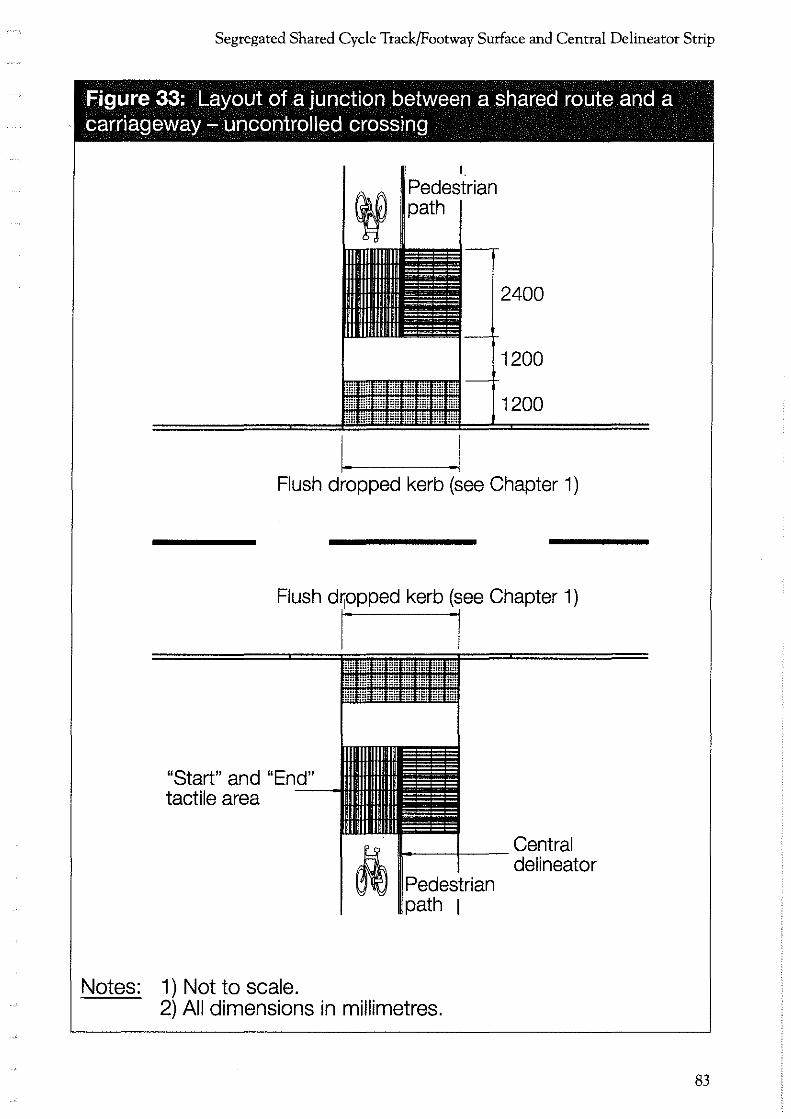
Segregated Shared Cycle Track/Footway Surface and Central Delineator Strip
Figure 33: Layout of a junction between a shared route and a carriageway - uncontrolled crossing
I_
Pedestrian
2400
1200
1200
I. Flush dropped kerb (see Chapter 1)
"Start" and "End" tactile area --
Notes: 1) Not to scale.
Central 1t 111----t--- delineator ~~ Pedestrian
path 1
2) All dimensions in millimetres.
83

Guidance on the use of Tactile Paving Surfaces
84
Figure 34: Layout at side road junctions - controlled crossings
- . I
Pedestrian path
2400
1200
1200
Flush dropped kerb (see Chapter 1) • • • • • • • • • •
Flush dropped kerb (see Chapter 1
"Start" and "End" tactile area --
Notes: 1) Not to scale.
r· ·1
A Pedestrian path 1
2) All dimensions in millimetres.
Central delineator
3) Additional control boxes provided on cyclist side on Toucan crossing. '-""
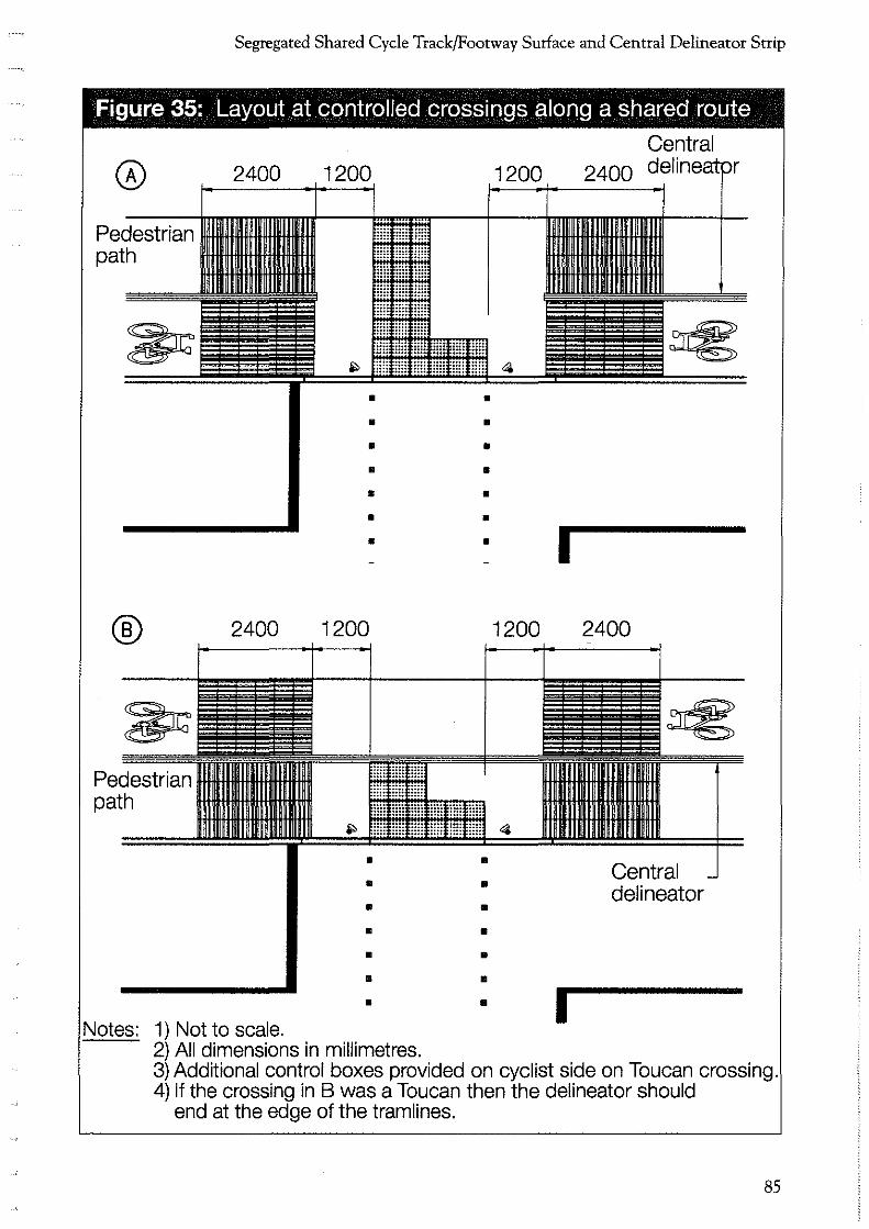
Segregated Shared Cycle Track/Footway Surface and Central Delineator Strip
Figure 35: Layout at controlled crossings along a shared route
Pedestrian path
®
~ Pedestrian path
2400
2400
Notes: 1) Not to scale.
• • • • • • •
1200
• • • • • • •
2) All dimensions in millimetres.
1200
• • • • • • •
1200
• • • • • • •
I
I
Central
2400
2400
Central delineator
3) Additional control boxes provided on cyclist side on Toucan crossing. 4) If the crossing in B was a Toucan then the delineator should
end at the edge of the tram lines.
85

L_-.,;,

Alllenity Surfaces


AMENITY SURFACES
CHAPTER 6
Guidance Path Surface This chapter should be read in conjunction with the advice in the Introduction.
6.1 Purpose
• The purpose of the guidance path surface is to guide visually impaired people along a route when the traditional cues, such as a property line or kerb edge, are not available. It can also be used to guide people around obstacles, for example street furniture in a pedestrianised area. The surface has been designed so that people can be guided along the route either by walking on the tactile surface or by maintaining contact with a long cane.
• To maximise its effectiveness the surface should be used sparingly and only after local consultation with relevant local groups.
6.2 Definition
• The profile of the guidance path surface comprises a series of raised, flat~topped bars running in the direction of pedestrian travel. The bars are 5.5mm (±0.5mm) high, 35mm wide and are spaced 45mm apart (Figure 36 page 90).
It is recommended that the guidance path be in a contrasting colour to the surrounding area so as to assist partially sighted people. It should not be red which is restricted to the blister surface at controlled crossings (see 1.5.1).
89

Guidance on the use of Tactile Paving Surfaces
Figure 36: Profile and plan of guidance path surface
2 2.5 45 1---
Notes: 1) Not to scale.
90
2) All dimensions in millimetres.
400 Front
35
_,
,-,
400
22.5 -
' / 10 ,_
, \
160
200
'--------'-
Alternative module size
. - ~ i
, ___ _;;
Guidance Path Surface
6.3 Application
The guidance path is recommended for use in the following circumstances:
• where the traditional guidance given by a standard footway between the property line and carriageway does not exist (for example, in a pedestrian precinct);
• where pedestrians need to be guided around obstacles (for example, in a pedestrian precinct): although care should be taken in siting street furniture to ensure that such problems are not created;
• where a number of visually impaired people need to find a specific location; and
• in transport terminals to guide people between facilities.
Before installing a guidance path, it is recommended that local authorities consult local visual impairment groups representing visually impaired people with regard to the route they would like the path to follow. This will ensure that the surface is used to best effect.
6.4 Maintenance
6.4.1 Condition of the surface
It is important to monitor the condition of the tactile surface and to plan for replacement as part of maintenance programmes. The profile of the tactile surface, as described in 6.2, is crucial to its effectiveness to visually impaired people.
At 5mm (the lower tolerance) the surface will still be effective. If the bars fall below that height the effectiveness of the surface will be reduced and it will ultimately be undetectable.
91
Guidance on the use of Tactile Paving Surfaces
6.4.2 New Roads and Street Works Act 1991
The New Roads and Street Works Act 1991 requires the replacement of the guidance surface when it is removed or disturbed in the course of opening the footway by the party disturbing the surface. It is essential that any reinstatement of the surface conforms with the advice in this document.
6.5 Layout
The exact layout of the guidance path will be site specific, but general advice is provided below.
6.5.1 Generallayout
92
• The surface should be installed with the bars running in the direction of pedestrian travel.
• The surface should be 800mm wide. If the path is laid to a width less than this, people may find it difficult to maintain contact with it.
• The path should be kept as straight as possible. People are more likely to lose contact with the surface at bends or junctions.
• The path should be laid so that it takes people along a safe and unobstructed route.
• Generally, there should be an unobstructed space of at least 800mm on either side of the path. This is needed to avoid people walking into obstacles if they stray off the path. It also allows space for a guide dog and provides a clear pathway for anyone who finds the surface uncomfortable.
• In busy shopping centres, a minimum width of 2000mm unobstructed space should be provided between the path and the property line.

Guidance Path Surface
This will reduce the likelihood of the guidance path being obstructed by other pedestrians, shop displays etc, and again, will provide a clear pathway away from the surface for those who may find it uncomfortable.
In planning the route care should be taken to avoid, wherever possible, inspection covers and street furniture which would interrupt the path.
6.5.2 Bends and junctions
• Where a right angle tum in the guidance path is necessary, the surface should be installed so that the bars run transversely across the direction of pedestrian travel for 1200mm (or as long as possible up to a maximum of 1200mm) before the bend in both directions (Figure 37 page 94). This will provide pedestrians walking towards the bend with advance warning that they are approaching a change in direction.
• Sharp bends should be avoided as they make it difficult to maintain contact with the path.
• Where a bend, other than a right angle tum, is necessary, the surface should be installed with the bars running in the direction of travel, and should be turned slightly to accommodate the bend (Figure 38 page 95 ).
• Where a junction is necessary to give the pedestrian a choice of routes, the guidance path surface should be installed with the bars running transversely for 1200mm (or as long as possible up to a maximum of 1200mm) before the intersection (Figure 39 page 96). At crossroads the surface in the central area of the junction should be orientated in the direction of the most heavily trafficked route.
People walking along the surface will be warned by the change in orientation of the surface that a change in direction is possible.
93

Guidance on the use of Tactile Paving Surfaces
Figure 37: Layout of guidance path surface at a right angle turn
~~~~~ ~ ~~
~ ~~ ~ ~ In this area slabs may be mitred if asthetically
I desirable, but it is not 1200 necessary to do so.
I
~ =
I = I = I = I
~ ~ ~ I = I = I = =
1200 .I Notes: 1) Not to scale.
2) All dimensions in millimetres.
l -'-'
94

Guidance Path Surface
Figure 38: Layout of guidance path surface at a turn other than a right angle
Notes: 1) Not to scale.
95

Guidance on the use of Tactile Paving Surfaces
Figure 39: Layout of guidance path surface at a 'T' junction and at a cross roads
1200
1200
lltll Notes: I) Not to scale.
2) All dimensions in millimetres.
96
800
Orientation of slabs in the shared area should be dictated by the most heavily trafficked route. The tactile paving on the more lightly trafficked route should be installed so that the bars run ransversely across the
pedestrian travel for 200mm before the hared area.
t
I s

CHAPTER 7
Information Surface
This chapter should be read in conjunction with the advice in the Introduction.
7.1 Purpose
The purpose of the information surface is to help people locate amenities, for example, a telephone box or a ticket office. It will be helpful to visually impaired people who are regular users of a particular area and will become familiar with the type of amenity indicated.
To maximise its effectiveness the surface should be used sparingly and only after local consultation with relevant local groups.
7.2 Definition
The information surface does not have a raised profile but is detectable because it feels slightly softer underfoot than conventional paving materials. The surface should have a matt finish and be slip resistant.
The information surface should be non-bituminous and based on a neoprene rubber or similar elastomeric compound. It should be available in a variety of colours as the use of a contrasting colour and tone to the surrounding footway is recommended so as to assist partially sighted people.
97

Guidance on the use of Tactile Paving Surfaces
7.3 Application
The surface can be used to draw attention to any amenity, such as:
• telephone kiosk;
• tactile or talking information board;
• entrances to civic amenities, resource centres etc.;
• ATMs (Automated Teller Machines, for example cash dispensers);
• toilets;
• waiting room; or
• ticket office.
Local visual impairment groups should be consulted prior to installation to determine which amenities they wish the surface to indicate.
7.4 Maintenance
7 .4.1 Condition of the surface
Monitoring of the information surface to ensure that it does not become pitted and uneven is essential to avoid the surface becoming a tripping hazard for pedestrians.
7.4.2 New Roads and Street Works Act 1991
98
The New Roads and Street Works Act 1991 requires the replacement of the information surface when it is removed or disturbed in the course of opening the footway by the party disturbing the surface. It is essential that any reinstatement of the surface conforms with the advice in this document.
Information Sutface
7.5 Layout
The exact layout of the information surface will be site specific, but general advice is provided below.
• The information surface material should be level with the surrounding footway. This is to avoid causing a trip hazard.
• A space of 400mm maximum should exist between the amenity and the start of the surface to allow people time to adjust their walking speed.
• Where the amenity is to one side of a footway, the surface should extend from the amenity to at least the centre of the footway (Figure 40 page 100). This will ensure it is detected by most visually impaired pedestrians.
• The surface should extend across the full width of the amenity or for 800mm, whichever is greater, except where the amenity is an entrance or window (eg. for a ticket office) when the surface must not extend beyond the width of the amenity.
• Where the path of pedestrian travel is not defined, for example in a pedestrian precinct, the surface should be laid across the width of the amenity and to a depth of between 400 and 800mm.
99

Guidance on the use of Tactile Paving Surfaces
Figure 40: Layout of information surface
@ In a precinct
Telephone kiosk
Up to 400 max
100
@ On a footway
800 max
or to the width of the amenity,
whichever is greater
Automated teller
machine
Up to 400 max
Centre line
8oo .1 or
to the width of the amenity, whichever is greater
Notes: 1) Not to scale. 2) All dimensions in millimetres.
Kerb

Glossary
The following descriptions relate to how these terms are used in the context of these guidelines:
Visually impaired people
Kerb upstand
Tactile paving
Controlled crossings
Uncontrolled crossings
Designated crossing point
Side road crossing
Signal controlled junctions without pedestrian phases, including those where studs indicating a pedestrian crossing place are provided.
People who are blind, deafblind, or partially sighted or have a severe vision loss
Vertical upstand 2:25mm
Profiled paving surface providing guidance or warning to visually impaired people
Pelican, zebra, puffin and toucan crossings and traffic signalled junctions with pedestrian phases.
Pedestrian crossing points where there is no level difference between the footway and the carriageway. Typically across side roads, or at locations away from junctions.
A pedestrian crossing point, controlled or uncontrolled, provided by the highway authority.
An uncontrolled crossing across the mouth of a side road at its intersection with another road.
These are uncontrolled crossings for the purposes of this guidance.
101
Guidance on the use of Tactile Paving Surfaces
Traffic calming
Side road entry treatment
Inset crossing
In~line crossing
Vehicle crossovers/ vehicle crossings
Busy crossovers/ vehicle crossings
Light rapid transit systems (LRT)
102
Influencing the characteristics of a road by physical measures in order to reduce and control vehicle speeds to a level commensurate with the activities taking place on that road.
An area of carriageway on a side road and the adjacent footway that is relaid to emphasise the area of the carriageway where pedestrians should be crossing and to encourage motorists to recognise the priority pedestrians have when crossing the side road.
Refers to a pedestrian crossing point, controlled or uncontrolled, which is located around a comer, at least one metre beyond the radius.
Refers to a pedestrian crossing point, controlled or uncontrolled, which is located in the direct line of travel of pedestrians moving along a footway.
Vehicle accesses intersecting a footway and providing access to residential and other facilities.
Vehicle accesses to facilities such as petrol stations, shopping centres, car parks, etc. associated with med/high traffic flows.
A system of public passenger transport which runs on a dedicated track or on street and includes monorails and people movers.

Contacts
Mobility Unit Department of the Environment, Transport and the Regions Zone 1/11 Great Minster House 76 Marsham Street London SW1P 4DR
Tel. 020-7944 6100 Minicom. 020-7944 3277 Fax. 020-7944 6102 [email protected]
Advice on the use of tactile surfaces.
RNIB/GDBA Joint Mobility Unit Royal National Institute for the Blind 224 Great Portland Street London W1N 6AA
Tel. 020-7387 2233 Fax. 020-7387 7109
Advice on the use of tactile surfaces, the mobility of visually impaired people and the selfinstructional training pack. Details of local visual impairment groups.
Traffic Director for London College House Great Peter Street London SW1P 3LN
Tel. 020-7233 0061 Fax. 020-7976 8640 E-mail. [email protected]
Advice on the design of side road entry treatments on priority (red) routes in London.
103

Reference Documents
LTN 2/95 "THE DESIGN OF PEDESTRIAN CROSSINGS" (Available from The Stationery Office - formerly HMSO -price £8.00)
CIVIC TRUST "TRAFFIC MEASURES IN HISTORIC TOWNS" (Available from The Civic Trust, 17 Carlton House Terrace, London SWl Y SAW)
TRAFFIC ADVISORY LEAFLET 4/91, "AUDIBLE AND TACTILE SIGNALS AT PELICAN CROSSINGS" (Available from Charging and Local Transport Division, Department of the Environment, Transport and the Regions, 76 Marsham Street, London SWlP 4DR)
104
TRAFFIC ADVISORY LEAFLET 5/91, "AUDIBLE AND TACTILE SIGNALS AT SIGNAL CONTROLLED JUNCTIONS" (Available from Charging and Local Transport Division, Department of the Environment, Transport and the Regions, 76 Marsham Street, London SWlP 4DR)


SCOTTISH EXECUTIVE
Produced by the Department of the Environment, Transport and the Regions © Crown Copyright 1998. Product code PPU1622RB
Printed in the UK April 2000 on paper comprising 75% post consumer waste and 25% ECF pulp.
'
... .~
r r r r r n n n r,
~
[
r
l
I,
l
l J
lJ
u u u Li
L
w LJ
LJ
w w