Grove GMK!#!$% - Allstate Crane Rental...
20
Features • 130 t (165 USt) capacity • 12,9 m - 60 m (42 ft - 197 ft) six-section full power MEGAFORM™ boom with TWIN-LOCK™ pinning • 11 m - 18 m (36 ft - 59 ft) bi-fold lattice swingaway, hydraulic luffing or manual offset • 3,6 m (12 ft) three-sheave heavy duty jib, hydraulic luffing integrated in swingaway • 375 kW (503 hp) Mercedes OM 502 LA 8-cylinder turbo-charged diesel engine. Daimler Chrysler, 16-speed G240-16 transmission. Two-stage transfer case • MEGATRAK™ independent hydro-pneumatic suspension Grove GMK5165-2 Product Guide ASME B30.5 Imperial 85%
Transcript of Grove GMK!#!$% - Allstate Crane Rental...
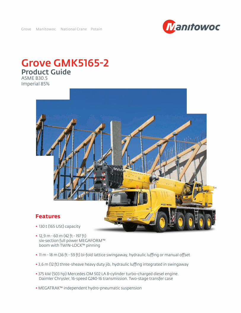
Features • 130 t (165 USt) capacity
• 12,9 m - 60 m (42 ft - 197 ft) six-section full power MEGAFORM™ boom with TWIN-LOCK™ pinning
• 11 m - 18 m (36 ft - 59 ft) bi-fold lattice swingaway, hydraulic luffing or manual offset
• 3,6 m (12 ft) three-sheave heavy duty jib, hydraulic luffing integrated in swingaway
• 375 kW (503 hp) Mercedes OM 502 LA 8-cylinder turbo-charged diesel engine. Daimler Chrysler, 16-speed G240-16 transmission. Two-stage transfer case
• MEGATRAK™ independent hydro-pneumatic suspension
Grove GMK5165-2Product GuideASME B30.5Imperial 85%
2
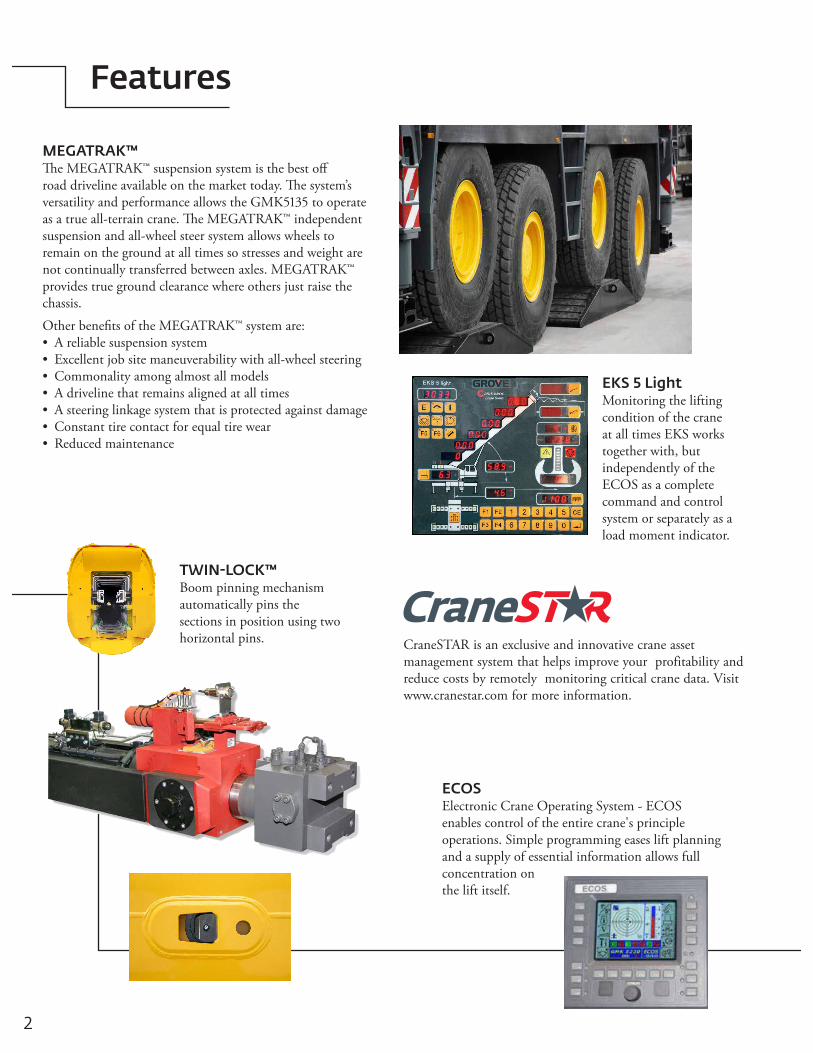
MEGATRAK™The MEGATRAK™ suspension system is the best off road driveline available on the market today. The system’s versatility and performance allows the GMK5135 to operate as a true all-terrain crane. The MEGATRAK™ independent suspension and all-wheel steer system allows wheels to remain on the ground at all times so stresses and weight are not continually transferred between axles. MEGATRAK™ provides true ground clearance where others just raise the chassis.Other benefits of the MEGATRAK™ system are:• A reliable suspension system• Excellent job site maneuverability with all-wheel steering• Commonality among almost all models• A driveline that remains aligned at all times• A steering linkage system that is protected against damage• Constant tire contact for equal tire wear• Reduced maintenance
ECOSElectronic Crane Operating System - ECOS enables control of the entire crane's principle operations. Simple programming eases lift planning and a supply of essential information allows full concentration on the lift itself.
TWIN-LOCK™Boom pinning mechanism automatically pins the sections in position using two horizontal pins.
Features
EKS 5 LightMonitoring the lifting condition of the crane at all times EKS works together with, but independently of the ECOS as a complete command and control system or separately as a load moment indicator.
CraneSTAR is an exclusive and innovative crane asset management system that helps improve your profitability and reduce costs by remotely monitoring critical crane data. Visit www.cranestar.com for more information.
Specifications 4
Dimensions 7
Weight proposals 8
Counterweight 9
Working range (main boom) 10
Load charts (main boom) 11
Working range (swingaway and inserts) 13
Load charts (hydraulically offsettable swingaway) 14
Working range (heavy duty jib) 16
Load charts (heavy duty jib) 17
Symbols glossary 19
Contents
4 *Denotes optional equipment
Specifications
Single lift cylinder with safety valve provides boomangle from -3° to +83°.
Boom elevation
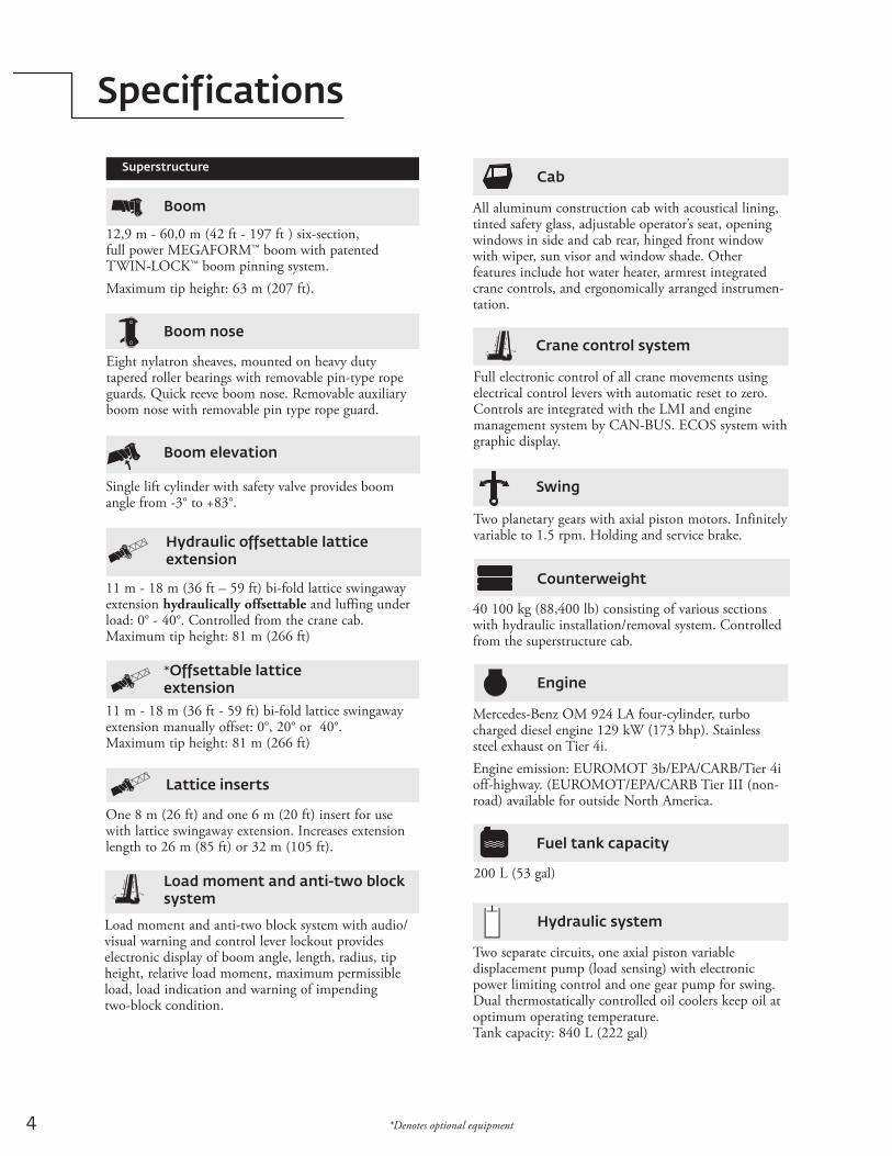
12,9 m - 60,0 m (42 ft - 197 ft ) six-section, full power MEGAFORM™ boom with patented TWIN-LOCK™ boom pinning system. Maximum tip height: 63 m (207 ft).
Boom
Superstructure
Eight nylatron sheaves, mounted on heavy duty tapered roller bearings with removable pin-type rope guards. Quick reeve boom nose. Removable auxiliary boom nose with removable pin type rope guard.
Boom nose
Load moment and anti-two block system with audio/visual warning and control lever lockout provides electronic display of boom angle, length, radius, tip height, relative load moment, maximum permissible load, load indication and warning of impending two-block condition.
Load moment and anti-two block system
All aluminum construction cab with acoustical lining, tinted safety glass, adjustable operator’s seat, opening windows in side and cab rear, hinged front window with wiper, sun visor and window shade. Other features include hot water heater, armrest integrated crane controls, and ergonomically arranged instrumen-tation.
Cab
Hydraulic offsettable lattice extension
11 m - 18 m (36 ft – 59 ft) bi-fold lattice swingaway extension hydraulically offsettable and luffing under load: 0° - 40°. Controlled from the crane cab. Maximum tip height: 81 m (266 ft)
Lattice inserts
One 8 m (26 ft) and one 6 m (20 ft) insert for use with lattice swingaway extension. Increases extension length to 26 m (85 ft) or 32 m (105 ft).
*Offsettable lattice extension
11 m - 18 m (36 ft - 59 ft) bi-fold lattice swingaway extension manually offset: 0°, 20° or 40°. Maximum tip height: 81 m (266 ft)
40 100 kg (88,400 lb) consisting of various sections with hydraulic installation/removal system. Controlled from the superstructure cab.
Counterweight
Mercedes-Benz OM 924 LA four-cylinder, turbo charged diesel engine 129 kW (173 bhp). Stainless steel exhaust on Tier 4i.Engine emission: EUROMOT 3b/EPA/CARB/Tier 4i off-highway. (EUROMOT/EPA/CARB Tier III (non- road) available for outside North America.
Engine
Two separate circuits, one axial piston variable displacement pump (load sensing) with electronic power limiting control and one gear pump for swing. Dual thermostatically controlled oil coolers keep oil at optimum operating temperature.Tank capacity: 840 L (222 gal)
Hydraulic system
Two planetary gears with axial piston motors. Infinitely variable to 1.5 rpm. Holding and service brake.
Swing
200 L (53 gal)
Fuel tank capacity
Full electronic control of all crane movements using electrical control levers with automatic reset to zero. Controls are integrated with the LMI and engine management system by CAN-BUS. ECOS system with graphic display.
Crane control system
5Grove GMK5165-2 *Denotes optional equipment
Specifications
400 L (106 gal)
Fuel tank capacity
24V system with three phase alternator, 28V/80A. 2 batteries, 12V/170 Ah.
Electrical system
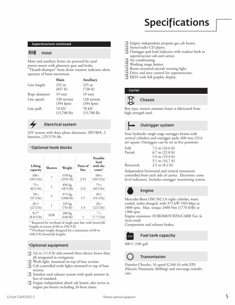
Main and auxiliary hoists are powered by axial piston motor with planetary gear and brake. “Thumb-thumper” hoist drum rotation indicator alerts operator of hoist movement. Main AuxiliaryLine length: 255 m 225 m (837 ft) (738 ft)Rope diameter: 19 mm 19 mmLine speed: 120 m/min 120 m/min (394 fpm) (394 fpm)Line pull: 70 kN 70 kN (15,700 lb) (15,700 lb)
Hoist
Superstructure continued
Carrier
Box type, torsion resistant frame is fabricated from high strength steel.
Chassis
Four hydraulic single stage outrigger beams with vertical cylinders and outrigger pads, 600 mm (23.6 in) square. Outriggers can be set in five positions:Full: 7,5 m (24.6 ft)Partial: 6,7 m (22.0 ft) 5,9 m (19.4 ft) 5,1 m (16.7 ft)Retracted: 2,5 m (8.2 ft)Independent horizontal and vertical movement controlled from each side of carrier. Electronic crane level indicators. Includes outrigger monitoring system.
Outrigger system
Daimler Chrysler, 16 speed G240-16 with EPS (Electric Pneumatic Shifting) and two-stage transfer case.
Transmission
Mercedes-Benz OM 502 LA eight cylinder, water cooled, turbo-charged, with 375 kW (503 bhp) at 1800 rpm. Max. torque 2400 Nm (1770 ft/lb) at 1300 rpm. Engine emissions: EUROMOT/EPA/CARB Tier 4i (non-road)Compression and exhaust brakes.
Engine
*Optional equipment
3,6 m (11.8 ft) side-stowed three-sheave heavy-duty jib integrated in swingaway. Work light, mounted on top of base section. Cab controlled work lights mounted to top of base section. Stainless steel exhaust system with spark arrestor in lieu of standard. Engine independent diesel cab heater, also serves as engine pre-heater including 24-hour timer.
Lifting capacity Sheaves Weight Parts of
line
Possible load
with the crane*
100 t(110 USt) 7 1150 kg
(2535 lb) 2-15100 t
(110 USt)75 t
(83 USt) 5 850 kg(1873 lb) 2-11
75 t(83 USt)
50 t(55 USt) 3 675 kg
(1488 lb) 1-749 t
(54 USt)20 t*
(22 USt) 1 325 kg(716 lb) 1-3
20 t(22 USt)
8 t**(8.8 USt) H/B 200 kg
(440 lb) 17 t
(7.7 USt)* Required for overhaul of single part line with boom/jib lengths in excess of 60 m (196.9 ft) **Overhaul weight designed for a maximum of 60 m (196.9 ft) boom/jib lengths
*Optional hook blocks
Engine independent propane gas cab heater. Stereo/radio CD player. Outrigger pad load indicator with readout both in superstructure cab and carrier. Air conditioning. Working range limiter. Boom mounted aircraft warning light. Drive and steer control for superstructure. EKS5 with full graphic display.
6 *Denotes optional equipment
Specifications
Work light; tool kit; fire extinguisher; auxiliary boom nose; radio/CD player in carrier cab, cruise control, wind speed indicator and working lights for each outrigger beam, CraneSTAR asset management system.
Miscellaneous standard equipment
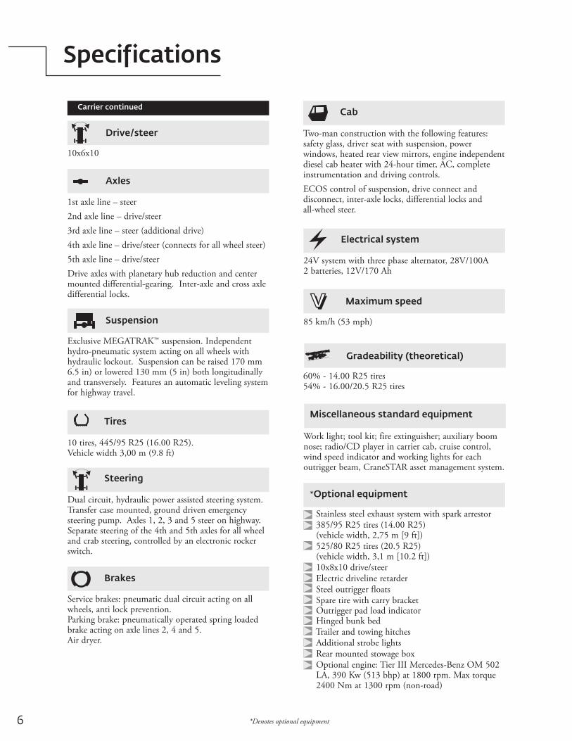
10 tires, 445/95 R25 (16.00 R25). Vehicle width 3,00 m (9.8 ft)
Tires
Dual circuit, hydraulic power assisted steering system. Transfer case mounted, ground driven emergency steering pump. Axles 1, 2, 3 and 5 steer on highway. Separate steering of the 4th and 5th axles for all wheel and crab steering, controlled by an electronic rocker switch.
Steering
24V system with three phase alternator, 28V/100A2 batteries, 12V/170 Ah
Electrical system
85 km/h (53 mph)
Maximum speed
60% - 14.00 R25 tires54% - 16.00/20.5 R25 tires
Gradeability (theoretical)
Service brakes: pneumatic dual circuit acting on all wheels, anti lock prevention. Parking brake: pneumatically operated spring loaded brake acting on axle lines 2, 4 and 5.Air dryer.
Brakes
Two-man construction with the following features: safety glass, driver seat with suspension, power windows, heated rear view mirrors, engine independent diesel cab heater with 24-hour timer, AC, complete instrumentation and driving controls. ECOS control of suspension, drive connect and disconnect, inter-axle locks, differential locks and all-wheel steer.
CabCarrier continued
Exclusive MEGATRAK™ suspension. Independent hydro-pneumatic system acting on all wheels with hydraulic lockout. Suspension can be raised 170 mm 6.5 in) or lowered 130 mm (5 in) both longitudinally and transversely. Features an automatic leveling system for highway travel.
Suspension
*Optional equipment
Stainless steel exhaust system with spark arrestor 385/95 R25 tires (14.00 R25) (vehicle width, 2,75 m [9 ft]) 525/80 R25 tires (20.5 R25) (vehicle width, 3,1 m [10.2 ft]) 10x8x10 drive/steer Electric driveline retarder Steel outrigger floats Spare tire with carry bracket Outrigger pad load indicator Hinged bunk bed Trailer and towing hitches Additional strobe lights Rear mounted stowage box Optional engine: Tier III Mercedes-Benz OM 502 LA, 390 Kw (513 bhp) at 1800 rpm. Max torque 2400 Nm at 1300 rpm (non-road)
1st axle line – steer2nd axle line – drive/steer3rd axle line – steer (additional drive)4th axle line – drive/steer (connects for all wheel steer)5th axle line – drive/steerDrive axles with planetary hub reduction and center mounted differential-gearing. Inter-axle and cross axle differential locks.
Axles
10x6x10
Drive/steer
7Grove GMK5165-2
Dimensions
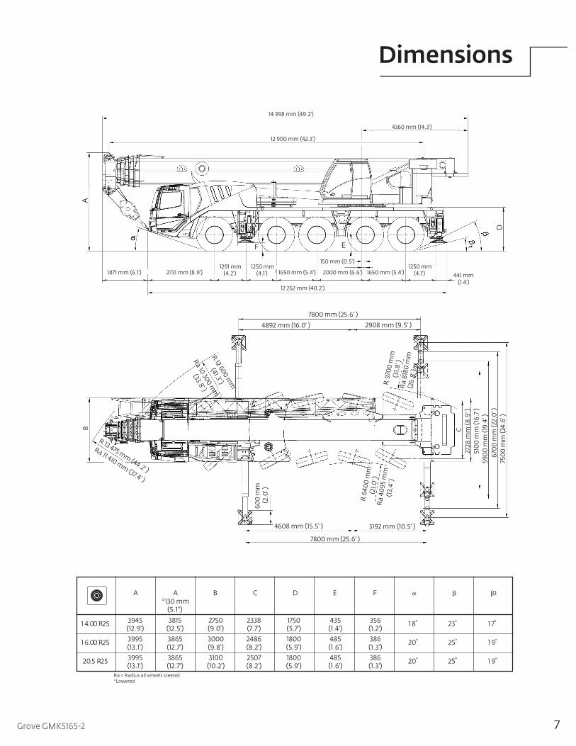
14 998 mm (49.2')
12 262 mm (40.2')
1650 mm (5.4') 1250 mm
(4.1') 2000 mm (6.6')
150 mm (0.5')
12 900 mm (42.3')
4360 mm (14.3')
441 mm (1.4')
1650 mm (5.4') 1250 mm
(4.1') 1291 mm
(4.2') 2731 mm (8.9') 1871 mm (6.1')
A
F
F
E
D
7800 mm (25.6' )4892 mm (16.0' ) 2908 mm (9.5' )
4608 mm (15.5' ) 3192 mm (10.5' )
7800 mm (25.6' )
2728
mm
(8.9
' )51
00 m
m (1
6.7 )
5900
mm
(19.
4' )
6700
mm
(22.
0' )
7500
mm
(24.
6' )
CB
600
mm
(2.0
' )
R 12 600 mm
(41.3' )
Ra 10 300 mm
(33.8' )
R 9
700
mm
(31.8
' )R
a 81
80 m
m (2
6.8'
)
R 13 475 mm (44.2' )
Ra 11 410 mm (37.4' )
R 6
400
mm
(21.0
' )R
a 40
95 m
m(1
3.4'
)
1 4.00 R25
A
3945(12.9')
A *130 mm
(5.1")3815
(12.5')
B
2750(9.0')
C
2338(7.7')
D
1750(5.7')
E
435(1.4')
F
356(1.2')
1 8° 23°
1
1 7°
1 6.00 R25 3995(13.1')
3865(12.7')
3000(9.8')
2486(8.2')
1800(5.9')
485(1.6')
386(1.3')
20° 25° 1 9°
20.5 R25 3995(13.1')
3865(12.7')
3100(10.2')
2507(8.2')
1800(5.9')
485(1.6')
386(1.3')
20° 25° 1 9°
*LoweredRa = Radius all wheels steered
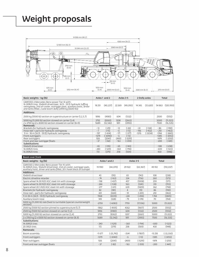
8
Boom over front
Basic weights - kg (lb) Axles 1 and 2 Axles 3-5 Total
GMK5165-2 Mercedes-Benz power Tier 4i with: 16.00R25 tires, 10x6x10 drive/steer, 2nd oil cooler, outrigger pads, auxiliary hoist, driver and tanks filled, 20 t hook block on bumper
19 990 (44,070) 29 922 (65,967) 49 912 (110,037)
Additions:10x8x10 drive/steer 43 (95) 65 (143) 108 (238)Electric driveline retarder - 74 (-163) 334 (736) 260 (573)Spare wheel 14.00 R25 XGC steel rim with stowage - 198 (-437) 457 (1008) 259 (571)Spare wheel 16.00 R25 XGC steel rim with stowage - 244 (-538) 563 (1241) 319 (703)Spare wheel 20.5 R25 XGC steel rim with stowage - 277 (-611) 639 (1409) 362 (798)Brackets for hydraulic swingaway 82 (181) 4 (9) 86 (190)Hose reel + parts for hydraulic swingaway 301 (664) - 91 (-201) 210 (463)11 m-18 m (36 ft - 59 ft) hydraulic swingaway 1968 (4339) - 224 (-494) 1 744 (3845)Auxiliary boom nose 149 (328) - 79 (-174) 70 (154)5000 kg (11,000 lb) slab fixed to turntable (special counterweight version) -2759 (-6083) 7759 (17,106) 5000 (11,023)
2500 kg (5500 lb) section pinned to superstructure (5,7) -1862 (-4105) 4362 (9617) 2500 (5512)2500 kg (5500 lb) section stowed on carrier (1,2) 1896 (4180) 604 (1332) 2500 (5512)5000 kg (11,000 lb) section stowed on carrier (3,4) 3793 (8362) 1207 (2661) 5000 (11,023)2 x 3760 kg (2 x 8300 lb) section stowed on carrier (8,9) 5689 (12,542) 1811 (3993) 7500 (16,535)Substitutions:14.00R25 tires - 240 (-529) - 360 (-794) - 600 (-1323)20.5R25 tires 172 (379) 258 (569) 430 (948)Removals: Boom assembly -11 677 (-25,743) -3541 (-7807) -15 218 (-33,550)Front outriggers -1379 (-3040) - 6 (-13) -1385 (-3053)Rear outriggers 926 (2041) -2400 (-5291) -1474 (-3250)Front and rear outrigger floats - 37 (-82) - 163 (-359) - 200 (-441)
Weight proposals
Basic weights - kg (lb) Axles 1 and 2 Axles 3-5 2 Dolly axles Total
GMK5165-2 Mercedes-Benz power Tier 4i with: 16.00R25 tires, 10x8x10 drive/steer, 36 ft - 59 ft hydraulic luffing swingaway, 2nd oil cooler, outrigger pads, auxiliary hoist, driver and tanks filled, 2 axle boom dolly (2994 kg [6600 lb])
18 251 (40,237) 22 269 (49,093) 14 343 (31,620) 54 863 (120,950)
Additions:
2500 kg (5500 lb) section on superstructure or carrier (1,2,5,7) 1896 (4180) 604 (1332) 2500 (5512)
5000 kg (11,000 lb) section stowed on carrier (3,4) 3792 (8360) 1208 (2663) 5000 (11,023)2 x 3750 kg (2 x 8300 lb) section stowed on carrier (8+9) 5689 (12,542) 1811 (3993) 7500 (16,535)Removals:Brackets for hydraulic swingaway - 13 (-29) - 12 (-26) - 61 (-134) - 86 (-190)Hose reel + parts for hydraulic swingaway - 7 (-15) - 6 (-13) - 196 (-432) - 210 (-463) 11 m - 18 m (36 ft - 59 ft) hydraulic swingaway - 197 (-434) - 171 (-377) -1376 (-3034) -1744 (-3845)Front outriggers -1379 (-3040) - 6 (-13) -1385 (-3053)Rear outriggers 926 (2041) -2400 (-5291) -1474 (-3250)Front and rear outrigger floats - 37 (-82) - 163 (-359) - 200 (-441)Substitutions:10x6x10 drive/steer - 43 (-95) - 65 (-143) - 108 (-238)14.00R25 tires - 240 (-529) - 360 (-794) - 600 (-1323)16.00R25 tires 172 (379) 258 (569) 430 (948)
14 998 mm (49.2')
4360 mm (14.3')
12 900 mm (42.3')
10 044 mm (33.0') 2540 mm (8.3')
5012 mm (16.4') 2540 mm (8.3') 2731 mm (9.0')2000 mm (6.6')1370 mm
(4.5')1650 mm
(5.4')1650 mm
(5.4')
686 mm (2.3')
2760 mm (9.0')
150 mm (0.5')
9Grove GMK5165-2
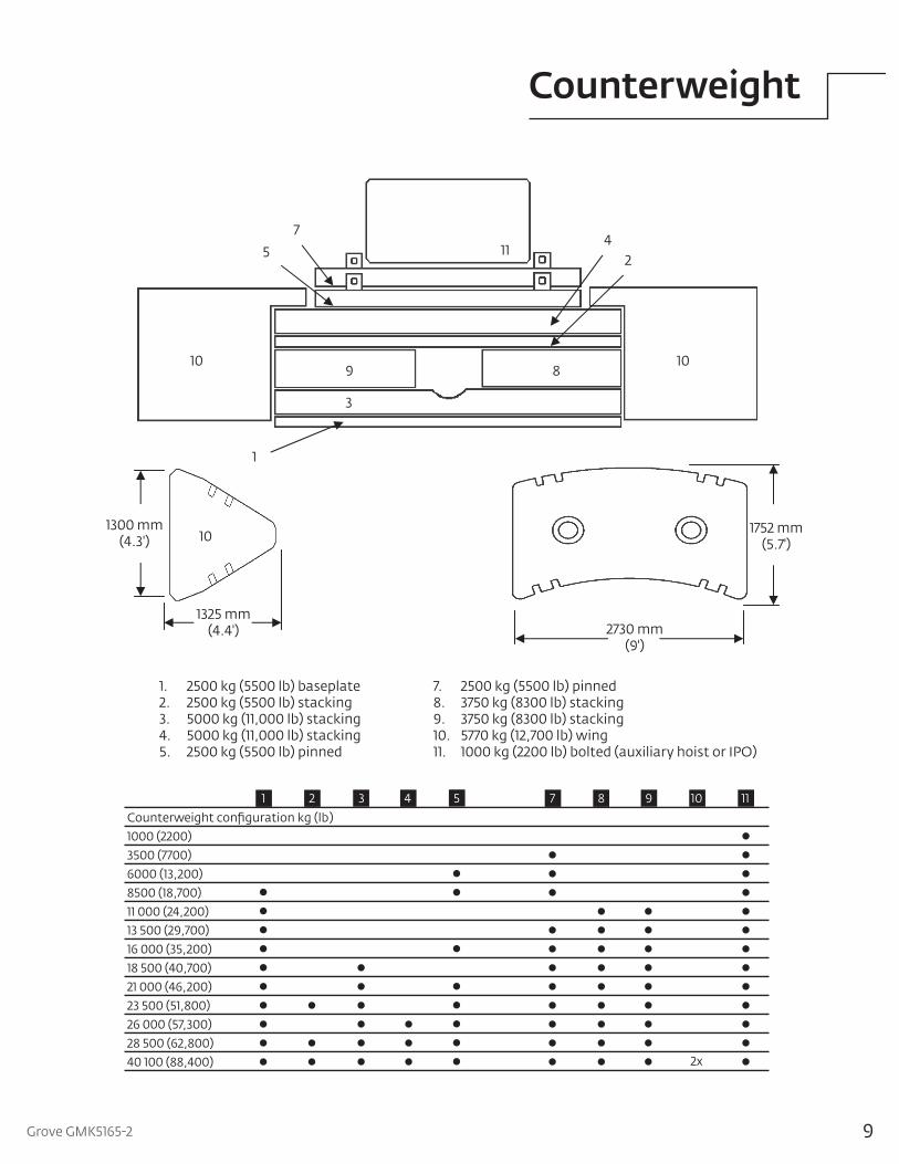
Counterweight
1
3
9 8
24
57
11
10 10
101300 mm
(4.3')
1325 mm(4.4')
Counterweight configuration kg (lb)1000 (2200)3500 (7700)6000 (13,200)8500 (18,700)11 000 (24,200)13 500 (29,700)16 000 (35,200)18 500 (40,700)21 000 (46,200)23 500 (51,800)26 000 (57,300)28 500 (62,800)40 100 (88,400)
21 3 4 5 7 8 9 10
2x
11
2730 mm(9')
1752 mm(5.7')
1. 2500 kg (5500 lb) baseplate 7. 2500 kg (5500 lb) pinned2. 2500 kg (5500 lb) stacking 8. 3750 kg (8300 lb) stacking3. 5000 kg (11,000 lb) stacking 9. 3750 kg (8300 lb) stacking4. 5000 kg (11,000 lb) stacking 10. 5770 kg (12,700 lb) wing 5. 2500 kg (5500 lb) pinned 11. 1000 kg (2200 lb) bolted (auxiliary hoist or IPO)
10
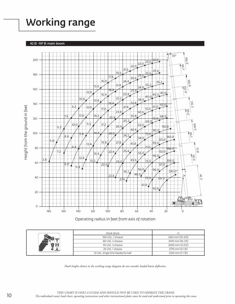
Working range
42 ft -197 ft main boom
Hook heights shown in the working range diagram do not consider loaded boom deflection.
Hook block100 USt, 7 sheave80 USt, 5 sheave45 USt, 3 sheave20 USt, 1 sheave
12 USt, single line headache ball
H3160 mm (10.4 ft)3070 mm (10.1 ft)3000 mm (9.8 ft)2770 mm (9.1 ft)2350 mm (7.7 ft)
THIS CHART IS ONLY A GUIDE AND SHOULD NOT BE USED TO OPERATE THE CRANE. The individual crane’s load chart, operating instructions and other instructional plates must be read and understood prior to operating the crane
180 160 140 120 100 80 60 40 20 0
20
0
40
60
80
100
120
140
160
180
200
58.0'89.1'
119.6'150.9'
181.7'
42.3' 73.8'
104.5'135.3'
83°
166.4'196.9'
22.022.022.0
19.6
16.0
12.0
9.2
6.2
3.8
22.0
21.6
17.8
13.6
10.8
7.6
5.0
25.625.6
25.625.6
24.421.4
18.816.4
13.8
12.0
11.0
10.0
8.6
7.2
35.235.2
34.829.8
25.822.2
19.4
17.0
14.2
11.6
9.8
8.8
8.0
45.045.045.0
38.432.8
27.423.8
20.8
17.2
14.8
13.4
12.4
11.4
62.061.0
51.042.6
35.830.2
26.4
24.0
19.8
15.2
16.6
20.0
22.4
27.8
34.2
42.452.0
60.072.0
84.0
110.090.0
72.054.0
41.8
35.4
29.0
23.8
143.0125.0
95.071.0
56.0
43.6
34.2
27.448.0
56.0
72.0
96.0132.0
186.0
199.0137.0
96.0
72.0
61.0
330.0*
136.0
92.0
Hei
ght f
rom
the
grou
nd in
feet
Operating radius in feet from axis of rotation
11Grove GMK5165-2 THIS CHART IS ONLY A GUIDE AND SHOULD NOT BE USED TO OPERATE THE CRANE. The individual crane’s load chart, operating instructions and other instructional plates must be read and understood prior to operating the crane
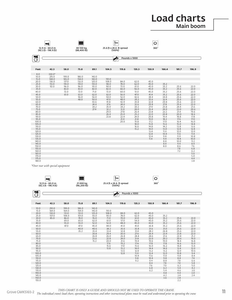
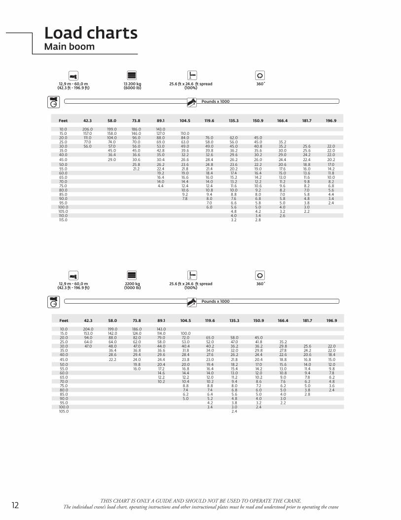
Load chartsMain boom
OutriggersCounterweight
12,9 m - 60,0 m 40 100 kg 25.6 ft x 24.6 ft spread 360˚ (42.3 ft - 196.9 ft) (88,400 lb) (100%)
Pounds x 1000Boom Extension
Feet 42.3 58.0 73.8 89.1 104.5 119.6 135.3 150.9 166.4 181.7 196.9
8.0 330.0*10.0 215.0 199.0 186.0 143.015.0 168.0 165.0 154.0 143.0 110.020.0 136.0 137.0 132.0 125.0 108.0 84.0 62.0 45.025.0 113.0 114.0 114.0 110.0 98.0 78.0 62.0 45.0 35.230.0 92.0 96.0 96.0 95.0 90.0 72.0 61.0 45.0 35.2 25.6 22.035.0 83.0 83.0 82.0 82.0 66.0 56.0 45.0 35.2 25.6 22.040.0 72.0 72.0 71.0 72.0 60.0 51.0 45.0 35.2 25.6 22.045.0 61.0 63.0 62.0 62.0 56.0 47.0 41.4 35.2 25.6 22.050.0 56.0 56.0 54.0 52.0 42.6 38.4 34.8 25.6 22.055.0 48.0 50.0 47.0 48.0 39.2 35.6 32.4 25.6 22.060.0 43.6 41.8 42.4 35.8 32.8 29.8 25.6 22.065.0 38.4 37.6 38.0 32.6 29.8 27.8 25.6 22.070.0 34.2 35.4 34.2 30.2 27.4 25.8 24.4 21.675.0 27.4 32.2 31.0 28.0 25.4 24.0 23.0 20.680.0 29.0 27.8 26.4 23.8 22.2 21.4 19.685.0 26.4 25.0 25.2 22.0 20.8 20.0 18.690.0 23.8 22.4 24.0 20.8 19.4 18.8 17.895.0 21.0 21.8 19.0 18.2 17.6 17.0
100.0 20.0 19.8 17.2 17.0 16.4 16.0105.0 18.0 15.8 15.6 15.0 14.8110.0 16.6 14.8 14.2 13.8 13.6115.0 15.2 14.0 13.0 12.8 12.8120.0 13.4 11.6 12.0 12.0125.0 12.8 10.4 11.6 11.4130.0 12.4 9.8 11.0 10.8135.0 11.4 9.4 10.4 10.0140.0 8.8 10.0 9.2145.0 8.4 9.4 8.4150.0 8.0 8.6 7.6155.0 7.8 6.8160.0 7.2 6.2165.0 5.6170.0 5.0175.0 4.4180.0 3.8
OutriggersCounterweight
12,9 m - 60,0 m 21 000 kg 25.6 ft x 24.6 ft spread 360˚ (42.3 ft - 196.9 ft) (46,200 lb) (100%)
Pounds x 1000Boom Extension
Feet 42.3 58.0 73.8 89.1 104.5 119.6 135.3 150.9 166.4 181.7 196.9
10.0 210.0 199.0 186.0 143.015.0 164.0 164.0 154.0 143.0 110.020.0 130.0 131.0 131.0 125.0 108.0 84.0 62.0 45.025.0 107.0 108.0 101.0 93.0 90.0 78.0 62.0 45.0 35.230.0 85.0 86.0 78.0 76.0 71.0 70.0 61.0 45.0 35.2 25.6 22.035.0 69.0 65.0 62.0 61.0 57.0 54.0 45.0 35.2 25.6 22.040.0 55.0 55.0 52.0 52.0 48.0 45.0 43.0 35.2 25.6 22.045.0 47.0 47.0 45.0 44.0 41.0 41.0 36.8 35.2 25.6 22.050.0 40.0 40.6 38.2 35.6 35.8 31.6 31.0 25.6 22.055.0 35.2 35.4 33.4 32.8 31.4 28.2 26.8 25.6 22.060.0 30.8 29.4 30.0 27.6 26.4 23.4 23.8 22.065.0 26.8 26.0 26.8 24.4 24.6 21.6 22.4 21.270.0 23.6 22.8 24.0 21.8 22.0 20.2 20.6 19.075.0 15.2 20.0 21.6 19.4 19.6 19.0 18.4 16.880.0 17.6 19.2 17.4 17.8 17.8 16.6 15.085.0 15.6 17.0 15.6 16.0 16.2 14.8 13.490.0 13.8 15.2 14.0 14.4 14.6 13.4 12.095.0 13.6 12.4 13.2 13.2 12.0 10.6
100.0 12.8 11.0 12.4 12.0 10.8 9.4105.0 10.4 11.6 11.0 9.8 8.4110.0 9.8 10.4 9.8 8.8 7.4115.0 9.2 9.4 8.8 7.8 6.6120.0 8.4 7.8 7.0 5.8125.0 7.6 7.0 6.2 5.0130.0 6.8 6.2 5.4 4.2135.0 6.2 5.4 4.6 3.6140.0 4.8 4.0 3.0145.0 4.2 3.4 2.4150.0 3.6 2.8155.0 2.2
*Over rear with special equipment
12
Load chartsMain boom
THIS CHART IS ONLY A GUIDE AND SHOULD NOT BE USED TO OPERATE THE CRANE. The individual crane’s load chart, operating instructions and other instructional plates must be read and understood prior to operating the crane
OutriggersCounterweight
12,9 m - 60,0 m 13 200 kg 25.6 ft x 24.6 ft spread 360˚ (42.3 ft - 196.9 ft) (6000 lb) (100%)
Pounds x 1000Boom Extension
Feet 42.3 58.0 73.8 89.1 104.5 119.6 135.3 150.9 166.4 181.7 196.9
10.0 206.0 199.0 186.0 143.015.0 157.0 158.0 146.0 127.0 110.020.0 111.0 104.0 96.0 88.0 84.0 76.0 62.0 45.025.0 77.0 74.0 70.0 69.0 63.0 58.0 56.0 45.0 35.230.0 56.0 57.0 56.0 53.0 49.0 49.0 45.0 40.8 35.2 25.6 22.035.0 45.0 45.0 42.8 39.6 39.8 36.2 35.6 30.0 25.6 22.040.0 36.4 36.6 35.0 32.2 32.6 29.6 30.2 29.0 24.2 22.045.0 29.0 30.6 30.4 26.6 28.4 26.2 26.0 24.4 22.4 20.250.0 25.8 26.2 23.6 24.8 23.6 22.2 20.6 18.8 17.055.0 21.2 22.4 21.8 21.4 20.2 19.0 17.6 16.0 14.260.0 19.2 19.0 18.4 17.4 16.4 15.0 13.6 11.865.0 16.4 16.6 16.0 15.2 14.2 13.0 11.6 10.070.0 14.0 14.4 14.0 13.2 12.2 11.2 9.8 8.275.0 4.4 12.4 12.4 11.6 10.6 9.6 8.2 6.880.0 10.6 10.8 10.0 9.2 8.2 7.0 5.685.0 9.2 9.4 8.8 8.0 7.0 5.8 4.490.0 7.8 8.0 7.6 6.8 5.8 4.8 3.495.0 7.0 6.6 5.8 5.0 3.8 2.4
100.0 6.0 5.6 5.0 4.0 3.0105.0 4.8 4.2 3.2 2.2110.0 4.0 3.4 2.6115.0 3.2 2.8
OutriggersCounterweight
12,9 m - 60,0 m 2200 kg 25.6 ft x 24.6 ft spread 360˚ (42.3 ft - 196.9 ft) (1000 lb) (100%)
Pounds x 1000Boom Extension
Feet 42.3 58.0 73.8 89.1 104.5 119.6 135.3 150.9 166.4 181.7 196.9
10.0 204.0 199.0 186.0 143.015.0 153.0 142.0 124.0 114.0 100.020.0 94.0 88.0 82.0 79.0 72.0 65.0 58.0 45.025.0 64.0 64.0 62.0 58.0 53.0 52.0 47.0 41.8 35.230.0 47.0 48.0 47.0 44.0 40.4 40.2 36.2 36.2 29.8 25.6 22.035.0 36.4 36.8 36.6 31.8 34.0 32.0 29.8 27.8 24.2 22.040.0 28.6 29.4 29.6 28.4 27.6 26.2 24.4 22.6 20.6 18.445.0 22.2 24.0 24.4 23.8 23.0 21.8 20.4 18.8 16.8 15.050.0 19.8 20.4 20.0 19.4 18.2 17.0 15.6 14.0 12.055.0 16.0 17.2 16.8 16.4 15.4 14.2 13.0 11.4 9.860.0 14.6 14.4 14.0 13.0 12.0 10.8 9.4 7.865.0 12.2 12.2 12.0 11.2 10.2 9.0 7.8 6.270.0 10.2 10.4 10.2 9.4 8.6 7.6 6.2 4.875.0 8.8 8.8 8.0 7.2 6.2 5.0 3.680.0 7.4 7.4 6.8 6.0 5.0 3.8 2.485.0 6.2 6.4 5.6 5.0 4.0 2.890.0 5.0 5.2 4.8 4.0 3.095.0 4.2 3.8 3.2 2.2
100.0 3.4 3.0 2.4105.0 2.4
13Grove GMK5165-2
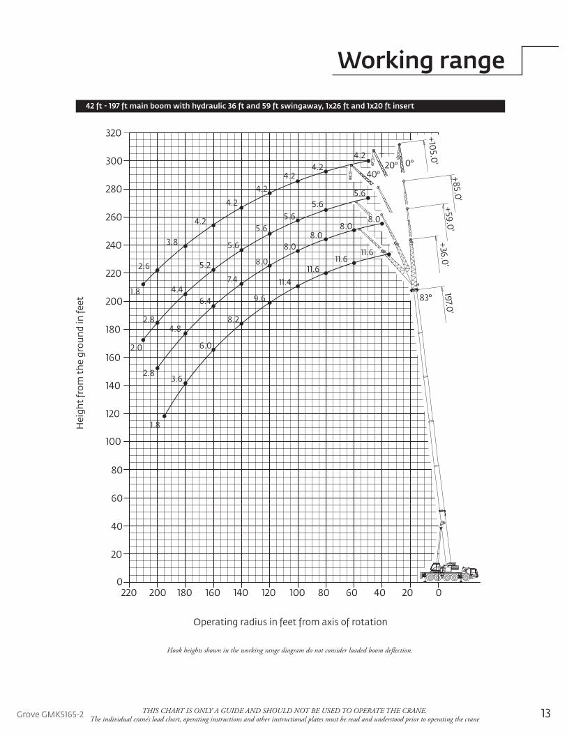
Working range
THIS CHART IS ONLY A GUIDE AND SHOULD NOT BE USED TO OPERATE THE CRANE. The individual crane’s load chart, operating instructions and other instructional plates must be read and understood prior to operating the crane
42 ft - 197 ft main boom with hydraulic 36 ft and 59 ft swingaway, 1x26 ft and 1x20 ft insert
Hook heights shown in the working range diagram do not consider loaded boom deflection.
0° 40°
+105.0'197.0'
83°
+59.0'+36.0'
20°
+85.0'
220 200 180 160 140 120 100 80 60 40 20 0
20
0
40
60
80
100
120
140
160
180
200
220
240
260
280
300
320
4.24.2
4.24.2
4.2
4.2
3.8
2.6
1.8
5.65.6
5.65.6
5.6
5.2
4.4
2.8
2.0
8.08.0
8.08.0
8.0
7.4
6.4
4.8
2.8
11.611.6
11.611.4
9.6
8.2
6.0
3.6
1.8Hei
ght f
rom
the
grou
nd in
feet
Operating radius in feet from axis of rotation
14THIS CHART IS ONLY A GUIDE AND SHOULD NOT BE USED TO OPERATE THE CRANE.
The individual crane’s load chart, operating instructions and other instructional plates must be read and understood prior to operating the crane
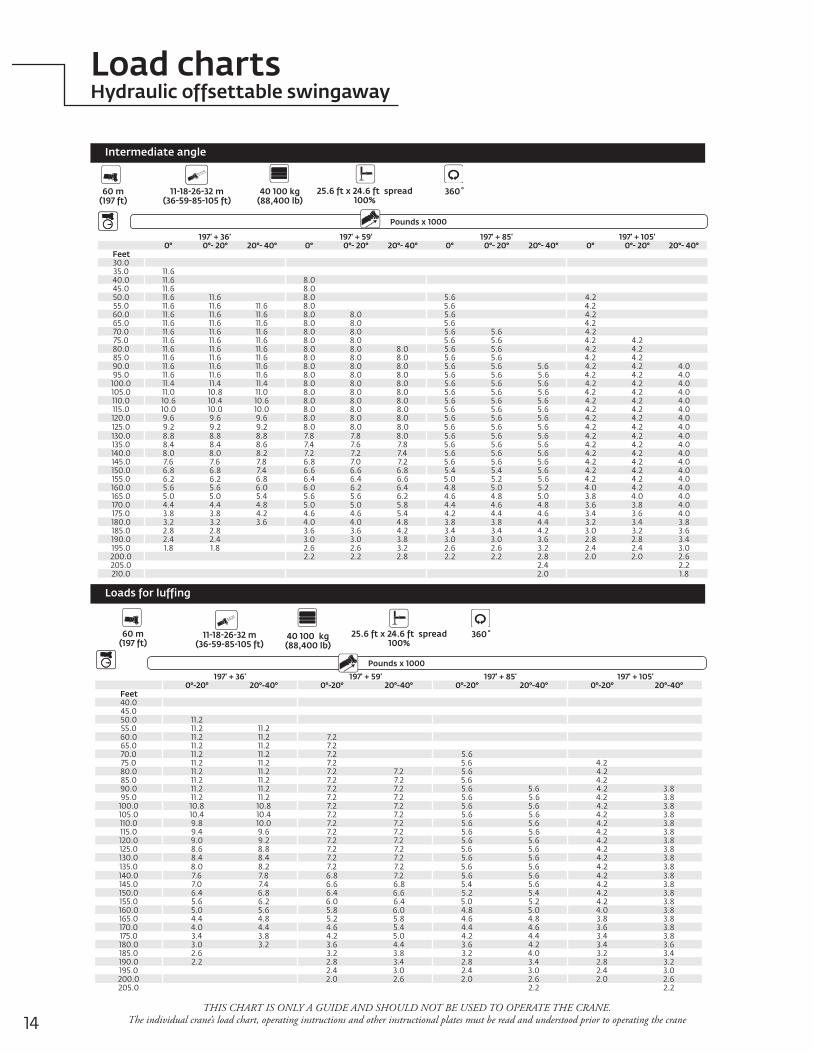
Load chartsHydraulic offsettable swingaway
197' + 36' 197' + 59' 197' + 85' 197' + 105'0° 0°- 20° 20°- 40° 0° 0°- 20° 20°- 40° 0° 0°- 20° 20°- 40° 0° 0°- 20° 20°- 40°
Feet30.035.0 11.640.0 11.6 8.045.0 11.6 8.050.0 11.6 11.6 8.0 5.6 4.255.0 11.6 11.6 11.6 8.0 5.6 4.260.0 11.6 11.6 11.6 8.0 8.0 5.6 4.265.0 11.6 11.6 11.6 8.0 8.0 5.6 4.270.0 11.6 11.6 11.6 8.0 8.0 5.6 5.6 4.275.0 11.6 11.6 11.6 8.0 8.0 5.6 5.6 4.2 4.280.0 11.6 11.6 11.6 8.0 8.0 8.0 5.6 5.6 4.2 4.285.0 11.6 11.6 11.6 8.0 8.0 8.0 5.6 5.6 4.2 4.290.0 11.6 11.6 11.6 8.0 8.0 8.0 5.6 5.6 5.6 4.2 4.2 4.095.0 11.6 11.6 11.6 8.0 8.0 8.0 5.6 5.6 5.6 4.2 4.2 4.0
100.0 11.4 11.4 11.4 8.0 8.0 8.0 5.6 5.6 5.6 4.2 4.2 4.0105.0 11.0 10.8 11.0 8.0 8.0 8.0 5.6 5.6 5.6 4.2 4.2 4.0110.0 10.6 10.4 10.6 8.0 8.0 8.0 5.6 5.6 5.6 4.2 4.2 4.0115.0 10.0 10.0 10.0 8.0 8.0 8.0 5.6 5.6 5.6 4.2 4.2 4.0120.0 9.6 9.6 9.6 8.0 8.0 8.0 5.6 5.6 5.6 4.2 4.2 4.0125.0 9.2 9.2 9.2 8.0 8.0 8.0 5.6 5.6 5.6 4.2 4.2 4.0130.0 8.8 8.8 8.8 7.8 7.8 8.0 5.6 5.6 5.6 4.2 4.2 4.0135.0 8.4 8.4 8.6 7.4 7.6 7.8 5.6 5.6 5.6 4.2 4.2 4.0140.0 8.0 8.0 8.2 7.2 7.2 7.4 5.6 5.6 5.6 4.2 4.2 4.0145.0 7.6 7.6 7.8 6.8 7.0 7.2 5.6 5.6 5.6 4.2 4.2 4.0150.0 6.8 6.8 7.4 6.6 6.6 6.8 5.4 5.4 5.6 4.2 4.2 4.0155.0 6.2 6.2 6.8 6.4 6.4 6.6 5.0 5.2 5.6 4.2 4.2 4.0160.0 5.6 5.6 6.0 6.0 6.2 6.4 4.8 5.0 5.2 4.0 4.2 4.0165.0 5.0 5.0 5.4 5.6 5.6 6.2 4.6 4.8 5.0 3.8 4.0 4.0170.0 4.4 4.4 4.8 5.0 5.0 5.8 4.4 4.6 4.8 3.6 3.8 4.0175.0 3.8 3.8 4.2 4.6 4.6 5.4 4.2 4.4 4.6 3.4 3.6 4.0180.0 3.2 3.2 3.6 4.0 4.0 4.8 3.8 3.8 4.4 3.2 3.4 3.8185.0 2.8 2.8 3.6 3.6 4.2 3.4 3.4 4.2 3.0 3.2 3.6190.0 2.4 2.4 3.0 3.0 3.8 3.0 3.0 3.6 2.8 2.8 3.4195.0 1.8 1.8 2.6 2.6 3.2 2.6 2.6 3.2 2.4 2.4 3.0200.0 2.2 2.2 2.8 2.2 2.2 2.8 2.0 2.0 2.6205.0 2.4 2.2210.0 2.0 1.8
Pounds x 1000Boom Extension
Outriggers
60 m (197 ft)
11-18-26-32 m (36-59-85-105 ft)
25.6 ft x 24.6 ft spread100%
360˚40 100 kg(88,400 lb)
Counterweight
Intermediate angle
Loads for luffing
Pounds x 1000Boom Extension
Outriggers
60 m (197 ft)
11-18-26-32 m(36-59-85-105 ft)
25.6 ft x 24.6 ft spread100%
360˚
Counterweight
197' + 36' 197' + 59' 197' + 85' 197' + 105'0°-20° 20°-40° 0°-20° 20°-40° 0°-20° 20°-40° 0°-20° 20°-40°
Feet40.045.050.0 11.255.0 11.2 11.260.0 11.2 11.2 7.265.0 11.2 11.2 7.270.0 11.2 11.2 7.2 5.675.0 11.2 11.2 7.2 5.6 4.280.0 11.2 11.2 7.2 7.2 5.6 4.285.0 11.2 11.2 7.2 7.2 5.6 4.290.0 11.2 11.2 7.2 7.2 5.6 5.6 4.2 3.895.0 11.2 11.2 7.2 7.2 5.6 5.6 4.2 3.8
100.0 10.8 10.8 7.2 7.2 5.6 5.6 4.2 3.8105.0 10.4 10.4 7.2 7.2 5.6 5.6 4.2 3.8110.0 9.8 10.0 7.2 7.2 5.6 5.6 4.2 3.8115.0 9.4 9.6 7.2 7.2 5.6 5.6 4.2 3.8120.0 9.0 9.2 7.2 7.2 5.6 5.6 4.2 3.8125.0 8.6 8.8 7.2 7.2 5.6 5.6 4.2 3.8130.0 8.4 8.4 7.2 7.2 5.6 5.6 4.2 3.8135.0 8.0 8.2 7.2 7.2 5.6 5.6 4.2 3.8140.0 7.6 7.8 6.8 7.2 5.6 5.6 4.2 3.8145.0 7.0 7.4 6.6 6.8 5.4 5.6 4.2 3.8150.0 6.4 6.8 6.4 6.6 5.2 5.4 4.2 3.8155.0 5.6 6.2 6.0 6.4 5.0 5.2 4.2 3.8160.0 5.0 5.6 5.8 6.0 4.8 5.0 4.0 3.8165.0 4.4 4.8 5.2 5.8 4.6 4.8 3.8 3.8170.0 4.0 4.4 4.6 5.4 4.4 4.6 3.6 3.8175.0 3.4 3.8 4.2 5.0 4.2 4.4 3.4 3.8180.0 3.0 3.2 3.6 4.4 3.6 4.2 3.4 3.6185.0 2.6 3.2 3.8 3.2 4.0 3.2 3.4190.0 2.2 2.8 3.4 2.8 3.4 2.8 3.2195.0 2.4 3.0 2.4 3.0 2.4 3.0200.0 2.0 2.6 2.0 2.6 2.0 2.6205.0 2.2 2.2
40 100 kg(88,400 lb)
15Grove GMK5165-2THIS CHART IS ONLY A GUIDE AND SHOULD NOT BE USED TO OPERATE THE CRANE.
The individual crane’s load chart, operating instructions and other instructional plates must be read and understood prior to operating the crane
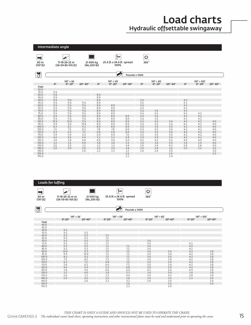
Load chartsHydraulic offsettable swingaway
197' + 36' 197' + 59' 197' + 85' 197' + 105'0° 0°- 20° 20°- 40° 0° 0°- 20° 20°- 40° 0° 0°- 20° 20°- 40° 0° 0°- 20° 20°- 40°
Feet30.035.0 11.640.0 11.6 8.045.0 11.6 8.050.0 11.6 11.6 8.0 5.6 4.255.0 11.6 11.6 11.6 8.0 5.6 4.260.0 11.6 11.6 11.6 8.0 8.0 5.6 4.265.0 11.6 11.6 11.6 8.0 8.0 5.6 4.270.0 11.6 11.6 11.6 8.0 8.0 5.6 5.6 4.275.0 11.6 11.6 11.6 8.0 8.0 5.6 5.6 4.2 4.280.0 11.6 11.6 11.6 8.0 8.0 8.0 5.6 5.6 4.2 4.285.0 11.6 11.6 11.6 8.0 8.0 8.0 5.6 5.6 4.2 4.290.0 10.6 10.6 11.6 8.0 8.0 8.0 5.6 5.6 5.6 4.2 4.2 4.095.0 9.4 9.4 10.4 8.0 8.0 8.0 5.6 5.6 5.6 4.2 4.2 4.0
100.0 8.2 8.2 9.2 8.0 8.0 8.0 5.6 5.6 5.6 4.2 4.2 4.0105.0 7.2 7.2 8.2 7.8 7.8 8.0 5.6 5.6 5.6 4.2 4.2 4.0110.0 6.2 6.2 7.2 6.8 6.8 8.0 5.6 5.6 5.6 4.2 4.2 4.0115.0 5.4 5.4 6.2 6.0 6.0 7.6 5.6 5.6 5.6 4.2 4.2 4.0120.0 4.6 4.6 5.4 5.2 5.2 6.8 5.0 5.0 5.6 4.2 4.2 4.0125.0 3.8 3.8 4.6 4.6 4.6 6.0 4.2 4.2 5.6 4.0 4.0 4.0130.0 3.2 3.2 4.0 3.8 3.8 5.2 3.6 3.6 5.0 3.4 3.4 4.0135.0 2.6 2.6 3.2 3.2 3.2 4.4 3.0 3.0 4.2 2.8 2.8 4.0140.0 2.0 2.0 2.6 2.6 2.6 3.8 2.4 2.4 3.6 2.2 2.2 3.6145.0 2.0 2.2 2.2 3.2 2.0 2.0 3.0 3.0150.0 2.6 2.6 2.4155.0 2.2 2.0
Pounds x 1000Boom Extension
Outriggers
60 m (197 ft)
11-18-26-32 m(36-59-85-105 ft)
25.6 ft x 24.6 ft spread100%
360˚21 000 kg(46,200 lb)
Counterweight
Intermediate angle
197' + 36' 197' + 59' 197' + 85' 197' + 105'0°-20° 20°-40° 0°-20° 20°-40° 0°-20° 20°-40° 0°-20° 20°-40°
Feet40.045.050.0 11.255.0 11.2 11.260.0 11.2 11.2 7.265.0 11.2 11.2 7.270.0 11.2 11.2 7.2 5.675.0 11.2 11.2 7.2 5.6 4.280.0 11.2 11.2 7.2 7.2 5.6 4.285.0 11.2 11.2 7.2 7.2 5.6 4.290.0 10.6 11.2 7.2 7.2 5.6 5.6 4.2 3.895.0 9.4 10.4 7.2 7.2 5.6 5.6 4.2 3.8
100.0 8.2 9.2 7.2 7.2 5.6 5.6 4.2 3.8105.0 7.2 8.2 7.2 7.2 5.6 5.6 4.2 3.8110.0 6.2 7.2 6.8 7.2 5.6 5.6 4.2 3.8115.0 5.4 6.2 6.0 7.2 5.6 5.6 4.2 3.8120.0 4.6 5.4 5.2 6.8 5.0 5.6 4.2 3.8125.0 3.8 4.6 4.6 6.0 4.2 5.6 4.0 3.8130.0 3.2 4.0 3.8 5.2 3.6 5.0 3.4 3.8135.0 2.6 3.2 3.2 4.4 3.0 4.2 2.8 3.8140.0 2.0 2.6 2.6 3.8 2.4 3.6 2.2 3.6145.0 2.0 2.2 3.2 2.0 3.0 3.0150.0 2.6 2.6 2.4155.0 2.2 2.0
Outriggers
60 m (197 ft)
11-18-26-32 m m(36-59-85-105 ft)
25.6 ft x 24.6 ft spread100%
360˚21 000 kg(46,200 lb)
Counterweight
Loads for luffing
Pounds x 1000Boom Extension
16THIS CHART IS ONLY A GUIDE AND SHOULD NOT BE USED TO OPERATE THE CRANE.
The individual crane’s load chart, operating instructions and other instructional plates must be read and understood prior to operating the crane.
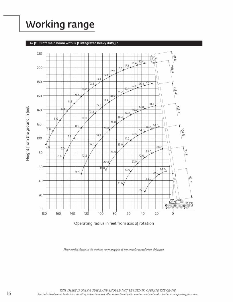
Working range
42 ft - 197 ft main boom with 12 ft integrated heavy duty jib
Hook heights shown in the working range diagram do not consider loaded boom deflection.
135.3'166.4
'
73.8'
104.5'
196.9'
42.3'
+11.8'
20
180 160 140 120 100 80 60 40 20 00
40
60
80
100
120
140
160
180
200
220
16.417.2
17.2
13.4
11.0
8.2
5.0
2.8
25.625.6
27.4
21.0
15.8
11.0
7.8
6.6
11.0
13.2
18.4
24.8
34.0
47.041.4
63.0
88.0
64.0
72.0
41.2
26.0
18.8
33.6
43.0 95.0
55.0
63.0
83.0
57.020.8
33.0
53.0
76.0
16.0
20.8
28.6
40.0
7.0
8.8
13.2
18.4
24.2
27.4
16.4
17.2
15.4
12.2
9.8
6.4
3.8
79.0
Hei
ght f
rom
the
grou
nd in
feet
Operating radius in feet from axis of rotation
17Grove GMK5165-2THIS CHART IS ONLY A GUIDE AND SHOULD NOT BE USED TO OPERATE THE CRANE.
The individual crane’s load chart, operating instructions and other instructional plates must be read and understood prior to operating the crane
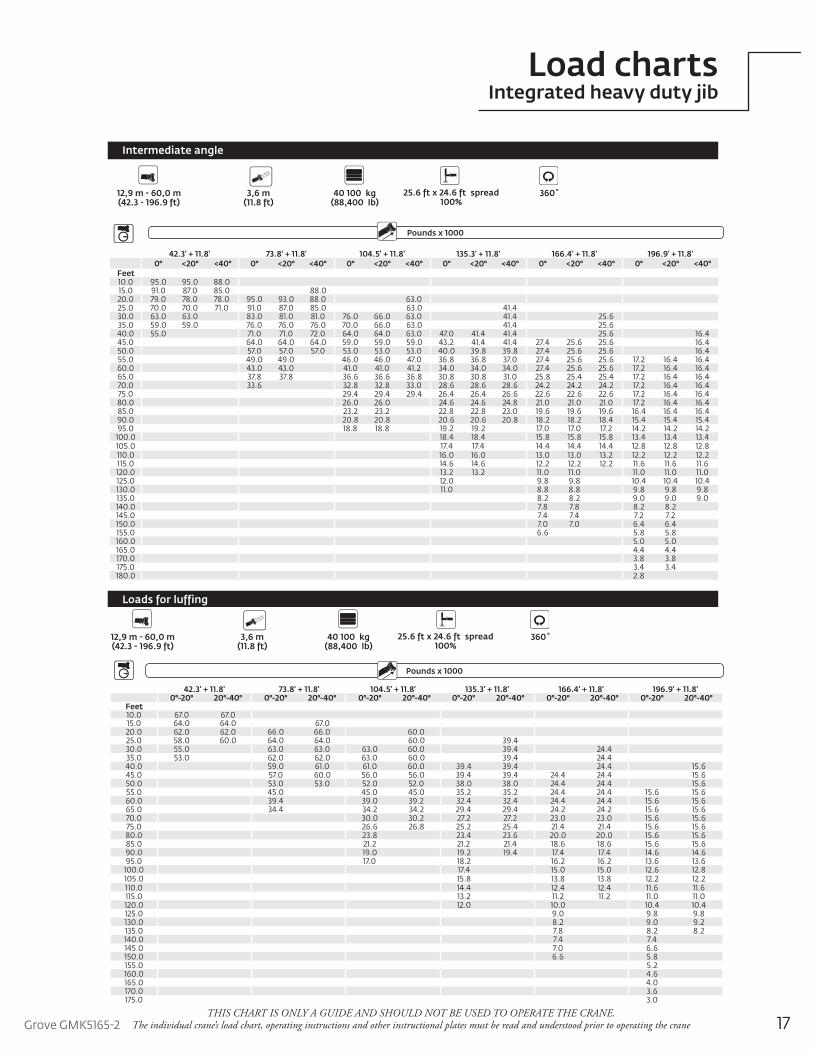
Intermediate angle
Load chartsIntegrated heavy duty jib
Loads for luffing
42.3' + 11.8' 73.8' + 11.8' 104.5' + 11.8' 135.3' + 11.8' 166.4' + 11.8' 196.9' + 11.8'0° <20° <40° 0° <20° <40° 0° <20° <40° 0° <20° <40° 0° <20° <40° 0° <20° <40°
Feet10.0 95.0 95.0 88.015.0 91.0 87.0 85.0 88.020.0 79.0 78.0 78.0 95.0 93.0 88.0 63.025.0 70.0 70.0 71.0 91.0 87.0 85.0 63.0 41.430.0 63.0 63.0 83.0 81.0 81.0 76.0 66.0 63.0 41.4 25.635.0 59.0 59.0 76.0 76.0 76.0 70.0 66.0 63.0 41.4 25.640.0 55.0 71.0 71.0 72.0 64.0 64.0 63.0 47.0 41.4 41.4 25.6 16.445.0 64.0 64.0 64.0 59.0 59.0 59.0 43.2 41.4 41.4 27.4 25.6 25.6 16.450.0 57.0 57.0 57.0 53.0 53.0 53.0 40.0 39.8 39.8 27.4 25.6 25.6 16.455.0 49.0 49.0 46.0 46.0 47.0 36.8 36.8 37.0 27.4 25.6 25.6 17.2 16.4 16.460.0 43.0 43.0 41.0 41.0 41.2 34.0 34.0 34.0 27.4 25.6 25.6 17.2 16.4 16.465.0 37.8 37.8 36.6 36.6 36.8 30.8 30.8 31.0 25.8 25.4 25.4 17.2 16.4 16.470.0 33.6 32.8 32.8 33.0 28.6 28.6 28.6 24.2 24.2 24.2 17.2 16.4 16.475.0 29.4 29.4 29.4 26.4 26.4 26.6 22.6 22.6 22.6 17.2 16.4 16.480.0 26.0 26.0 24.6 24.6 24.8 21.0 21.0 21.0 17.2 16.4 16.485.0 23.2 23.2 22.8 22.8 23.0 19.6 19.6 19.6 16.4 16.4 16.490.0 20.8 20.8 20.6 20.6 20.8 18.2 18.2 18.4 15.4 15.4 15.495.0 18.8 18.8 19.2 19.2 17.0 17.0 17.2 14.2 14.2 14.2
100.0 18.4 18.4 15.8 15.8 15.8 13.4 13.4 13.4105.0 17.4 17.4 14.4 14.4 14.4 12.8 12.8 12.8110.0 16.0 16.0 13.0 13.0 13.2 12.2 12.2 12.2115.0 14.6 14.6 12.2 12.2 12.2 11.6 11.6 11.6120.0 13.2 13.2 11.0 11.0 11.0 11.0 11.0125.0 12.0 9.8 9.8 10.4 10.4 10.4130.0 11.0 8.8 8.8 9.8 9.8 9.8135.0 8.2 8.2 9.0 9.0 9.0140.0 7.8 7.8 8.2 8.2145.0 7.4 7.4 7.2 7.2150.0 7.0 7.0 6.4 6.4155.0 6.6 5.8 5.8160.0 5.0 5.0165.0 4.4 4.4170.0 3.8 3.8175.0 3.4 3.4180.0 2.8
Pounds x 1000Boom Extension
Outriggers
12,9 m - 60,0 m (42.3 - 196.9 ft)
3,6 m(11.8 ft)
25.6 ft x 24.6 ft spread100%
360˚40 100 kg(88,400 lb)
Counterweight
42.3' + 11.8' 73.8' + 11.8' 104.5' + 11.8' 135.3' + 11.8' 166.4' + 11.8' 196.9' + 11.8'0°-20° 20°-40° 0°-20° 20°-40° 0°-20° 20°-40° 0°-20° 20°-40° 0°-20° 20°-40° 0°-20° 20°-40°
Feet10.0 67.0 67.015.0 64.0 64.0 67.020.0 62.0 62.0 66.0 66.0 60.025.0 58.0 60.0 64.0 64.0 60.0 39.430.0 55.0 63.0 63.0 63.0 60.0 39.4 24.435.0 53.0 62.0 62.0 63.0 60.0 39.4 24.440.0 59.0 61.0 61.0 60.0 39.4 39.4 24.4 15.645.0 57.0 60.0 56.0 56.0 39.4 39.4 24.4 24.4 15.650.0 53.0 53.0 52.0 52.0 38.0 38.0 24.4 24.4 15.655.0 45.0 45.0 45.0 35.2 35.2 24.4 24.4 15.6 15.660.0 39.4 39.0 39.2 32.4 32.4 24.4 24.4 15.6 15.665.0 34.4 34.2 34.2 29.4 29.4 24.2 24.2 15.6 15.670.0 30.0 30.2 27.2 27.2 23.0 23.0 15.6 15.675.0 26.6 26.8 25.2 25.4 21.4 21.4 15.6 15.680.0 23.8 23.4 23.6 20.0 20.0 15.6 15.685.0 21.2 21.2 21.4 18.6 18.6 15.6 15.690.0 19.0 19.2 19.4 17.4 17.4 14.6 14.695.0 17.0 18.2 16.2 16.2 13.6 13.6
100.0 17.4 15.0 15.0 12.6 12.8105.0 15.8 13.8 13.8 12.2 12.2110.0 14.4 12.4 12.4 11.6 11.6115.0 13.2 11.2 11.2 11.0 11.0120.0 12.0 10.0 10.4 10.4125.0 9.0 9.8 9.8130.0 8.2 9.0 9.2135.0 7.8 8.2 8.2140.0 7.4 7.4145.0 7.0 6.6150.0 6.6 5.8155.0 5.2160.0 4.6165.0 4.0170.0 3.6175.0 3.0
Outriggers
12,9 m - 60,0 m (42.3 - 196.9 ft)
3,6 m(11.8 ft)
25.6 ft x 24.6 ft spread100%
360˚40 100 kg(88,400 lb)
Counterweight
Pounds x 1000Boom Extension
18
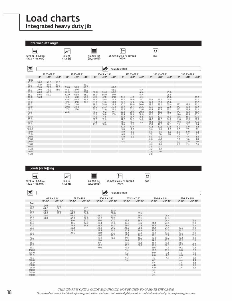
Load chartsIntegrated heavy duty jib
THIS CHART IS ONLY A GUIDE AND SHOULD NOT BE USED TO OPERATE THE CRANE. The individual crane’s load chart, operating instructions and other instructional plates must be read and understood prior to operating the crane.
42.3' + 11.8' 73.8' + 11.8' 104.5' + 11.8' 135.3' + 11.8' 166.4' + 11.8' 196.9' + 11.8'0° <20° <40° 0° <20° <40° 0° <20° <40° 0° <20° <40° 0° <20° <40° 0° <20° <40°
Feet10.0 95.0 95.0 88.015.0 91.0 87.0 85.0 88.020.0 79.0 78.0 78.0 95.0 93.0 88.0 63.025.0 70.0 70.0 71.0 91.0 87.0 85.0 63.0 41.430.0 63.0 63.0 76.0 76.0 77.0 68.0 66.0 63.0 41.4 25.635.0 59.0 59.0 62.0 62.0 63.0 56.0 56.0 57.0 41.4 25.640.0 55.0 51.0 51.0 52.0 47.0 47.0 47.0 43.0 41.4 41.4 25.6 16.445.0 43.4 43.4 43.8 39.4 39.4 39.8 36.6 36.6 37.2 27.4 25.6 25.6 16.450.0 37.0 37.0 37.4 33.6 33.6 34.0 32.6 32.6 32.6 27.4 25.6 25.6 16.455.0 32.0 32.0 29.0 29.0 29.4 30.0 30.0 30.0 25.6 25.6 25.6 17.2 16.4 16.460.0 29.8 29.8 25.2 25.2 25.4 26.4 26.4 26.6 22.2 22.2 22.6 17.2 16.4 16.465.0 27.0 27.0 22.0 22.0 22.2 23.2 23.2 23.6 19.4 19.4 19.6 17.2 16.4 16.470.0 23.8 19.2 19.2 19.4 20.6 20.6 20.8 18.2 18.2 18.2 17.2 16.4 16.475.0 16.8 16.8 17.0 18.4 18.4 18.6 16.6 16.6 17.0 15.4 15.4 15.680.0 14.6 14.6 16.4 16.4 16.6 15.0 15.0 15.8 13.6 13.6 13.885.0 12.6 12.6 14.6 14.6 14.8 14.0 14.0 14.2 12.0 12.0 12.290.0 11.2 11.2 13.0 13.0 13.2 13.2 13.2 13.4 10.6 10.6 10.695.0 10.6 10.6 11.6 11.6 12.0 12.0 12.0 9.2 9.2 9.4
100.0 10.4 10.4 10.6 10.6 10.8 8.0 8.0 8.2105.0 9.0 9.0 9.6 9.6 9.6 7.0 7.0 7.2110.0 8.0 8.0 8.6 8.6 8.6 6.0 6.0 6.2115.0 6.8 6.8 7.6 7.6 7.8 5.2 5.2 5.2120.0 6.0 6.0 6.8 6.8 4.4 4.4 4.4125.0 5.2 6.0 6.0 3.6 3.6 3.8130.0 4.4 5.2 5.2 3.0 3.0 3.0135.0 4.4 4.4 2.4 2.4 2.4140.0 3.8 3.8145.0 3.2 3.2150.0 2.6 2.6155.0 2.0
Intermediate angle
Outriggers
12,9 m - 60,0 m (42.3 - 196.9 ft)
3,6 m(11.8 ft)
25.6 ft x 24.6 ft spread100%
360˚46 200 kg(21,000 lb)
Counterweight
42.3' + 11.8' 73.8' + 11.8' 104.5' + 11.8' 135.3' + 11.8' 166.4' + 11.8' 196.9' + 11.8'0°-20° 20°-40° 0°-20° 20°-40° 0°-20° 20°-40° 0°-20° 20°-40° 0°-20° 20°-40° 0°-20° 20°-40°
Feet10.0 67.0 67.015.0 64.0 64.0 67.020.0 62.0 62.0 66.0 66.0 60.025.0 58.0 60.0 64.0 64.0 60.0 39.430.0 55.0 63.0 63.0 63.0 60.0 39.4 24.435.0 53.0 62.0 62.0 56.0 57.0 39.4 24.440.0 51.0 51.0 47.0 47.0 39.4 39.4 24.4 15.645.0 41.6 42.0 39.4 39.8 36.6 37.2 24.4 24.4 15.650.0 34.6 34.8 33.6 34.0 31.4 31.8 24.4 24.4 15.655.0 30.4 28.8 29.2 28.6 28.6 24.4 24.4 15.6 15.660.0 28.2 24.4 24.6 26.4 26.6 22.2 22.6 15.6 15.665.0 24.6 21.0 21.0 23.2 23.6 19.4 19.6 15.6 15.670.0 18.0 18.0 20.4 20.6 17.2 17.2 15.6 15.675.0 15.4 15.6 17.8 18.0 15.8 16.2 15.4 15.680.0 13.4 15.6 15.8 14.2 15.0 13.6 13.885.0 11.4 13.8 13.8 13.4 13.6 12.0 12.290.0 10.6 12.2 12.2 12.6 12.8 10.6 10.695.0 10.0 10.6 11.6 11.6 9.2 9.4
100.0 9.4 10.2 10.4 8.0 8.2105.0 8.2 9.0 9.2 7.0 7.2110.0 7.2 8.0 8.0 6.0 6.2115.0 6.2 7.0 7.2 5.4 5.2120.0 5.4 6.2 4.4 4.4125.0 5.4 3.6 3.8130.0 4.8 3.0 3.0135.0 4.0 2.4 2.4140.0 3.4145.0 2.8150.0 2.4
Outriggers
12,9 m - 60,0 m (42.3 - 196.9 ft)
3,6 m(11.8 ft)
25.6 ft x 24.6 ft spread100%
360˚46 200 kg(21,000 lb)
Counterweight
Loads for luffing
Pounds x 1000Boom Extension
Pounds x 1000Boom Extension
Grove GMK5165-2 19
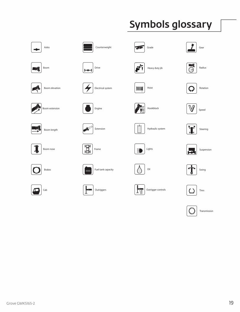
Symbols glossary
Drive
RotationElectrical system
Suspension
Fuel tank capacity
Tires
Engine
Brakes
Outrigger controls
Axles
Outriggers
Transmission
Frame
Steering
Lights
Boom elevation
Cab
Swing
Hydraulic system
Hoist
Boom nose
Radius
Boom extension
Boom length
Grade Gear
Boom
Counterweight
Speed
Oil
Extension
HookblockH
Heavy duty jib

©2015ManitowocForm No. GMK5165-2 PGPart No. 08-004 / PDF / 0715 www.manitowoccranes.com
This document is non-contractual. Constant improvement and engineering progress make it necessary that we reserve the right to make specification, equipment, and price changes without notice. Illustrations shown may include optional equipment and accessories and may not include all standard equipment.
Regional offices
ChinaShanghai, China Tel: +86 21 6457 0066Fax: +86 21 6457 4955
Greater Asia-Pacific Singapore Tel: +65 6264 1188 Fax: +65 6862 4040
Europe, Middle East, Africa Dardilly, France Tel: +33 (0)4 72 18 20 20 Fax: +33 (0)4 72 18 20 00
Americas Manitowoc, Wisconsin, USA Tel: +1 920 684 6621 Fax: +1 920 683 6277Shady Grove, Pennsylvania, USA Tel: +1 717 597 8121 Fax: +1 717 597 4062
Regional headquarters
Manitowoc Cranes
ChinaBeijingChengduGuangzhouXian
Greater Asia-PacificAustraliaBrisbaneSydneyIndiaAhmedabadBengaluruChennaiGurgaonHyderabadKolkataMumbaiNoidaPuneKoreaSeoulPhilippinesMakati CitySingapore
FactoriesBrazilPasso FundoChinaZhangjiagangFranceCharlieuMoulinsGermanyWilhelmshavenIndiaPuneItalyNiella TanaroPortugalBaltarFânzeresUSAManitowoc Port WashingtonShady Grove
AmericasBrazilAlphavilleMexicoMonterreyChileSantiago
Europe, Middle East, AfricaFranceDardillySaint Pierre de ChandieuGermanyLangenfeldItalyLainateNetherlandsBredaPolandWarsawPortugalBaltarRussiaMoscowSouth AfricaJohannesburgU.A.E.DubaiU.K.Buckingham