GMK Revision System Surgical Technique US … · 16.1 GMK Revision 22 16.2 GMK Hinge 22 17 FINAL...
64
Hip Knee Spine Navigation DIFFERENT NEEDS ... ... YOUR GLOBAL SOLUTION Surgical Technique Surgical Technique GLOBAL MEDACTA K NEE REVISION SYSTEM
Transcript of GMK Revision System Surgical Technique US … · 16.1 GMK Revision 22 16.2 GMK Hinge 22 17 FINAL...
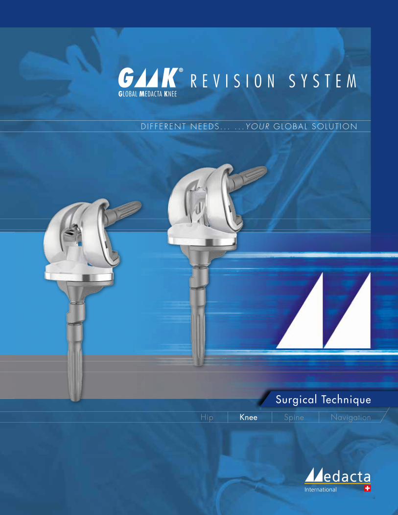
Hip Knee Spine Navigation
D I F F E R ENT NEEDS . . . . . .YOUR G LOBA L SO LUT ION
Surgical TechniqueSurgical Technique
GLOBAL MEDACTA KNEE R E V I S I O N S Y S T E M

2
GMK REVISION SYSTEM Surgical Technique Hip Knee Spine Navigation
Medacta International would like to express its gratitude to
DR. GILLES GAGNAClinique du Pré,Les Mans, France
DR. PETER KOCHKantospital WinterthurWinterthur, Switzerland
for their valuable and constant help in GMK Revision and GMK Hinge implant, instruments and surgical technique development.
A special thanks to
DAVID MANNING, MDNorthwestern UniversityChicago, ILUSA
for his support during the surgical technique finalization.
A K N O W L E D G M E N T S
PROF. ALFREDO RODRIGUEZUniversity Rovira I Virgili,Tarragona, Spain
DR. JOSEP M. SEGURHospital ClinicoBarcelona, Spain
I N T R O D U C T I O NThe GMK® Revision and GMK®Hinge can be implanted following different surgical techniques, according to the surgeon's preferences and habits.
The technique herein described can be used in both tibia first and femur first approaches.
The primary goal of a GMK® Revision and GMK® Hinge knee replacement include the restoration of anatomical alignment and functional stability, the accurate reestablishment of the joint line and the fixation and stabilization of the revision prostethic implant components.

3
Some specific instruments are fixed to the bone by means of dedicated pins. Before using the pins, ensure that they are intact and fully functional. BENT OR DEFECTIVE PINS CANNOT BE USED AND MUST BE REPLACED BY NEW ONES. Pins extarction must be performed avoiding any bending. This result in axial alignment between the pin and the dedicated extractor. It is strongly recommended not to impact or hammer any instruments unless otherwise specified in the surgical technique.For detailed instructions contact your local Medacta sales representative.
C A U T I O N
Incorrect assembling of the hinge-post mechanism may lead to early mechanical failure of this mechanism. Following the correct procedure to assemble all the implant modular connections as described herein is crucial for the implant survival rate. A quick reference guide for implant assembly is provided in Annex 1.
Federal law (USA) restricts this device to be sold by or on order by any physician. Please, consider the package insert for complete product information.
C A U T I O N
C A U T I O N
4
GMK REVISION SYSTEM Surgical Technique Hip Knee Spine Navigation
1 INTRODUCTION 6
2 INDICATION OF USE 6
3 PRE-OPERATIVE PLANNING 7
4 PRIMARY IMPLANT REMOVAL 7
5 JOINT LINE AND JOINT SPACE ASSESSMENT 7
6 TIBIAL RESECTION 7
7 TIBIAL AUGMENTS (optional) 9
8 TIBIAL BASEPLATE POSITIONING 10
9 TIBIA FINISHING 11
10 TRIAL TIBIAL COMPONENT 13 10.1 Tibia without offset 14 10.2 3 mm or 5 mm tibial offset 15
11 FEMORAL SIZE DEFINITION 16
12 FEMUR FINISHING 16
13 TRIAL FEMORAL COMPONENT 18 13.1 Femur without offset 18 13.2 3 mm offset option 19
14 FEMORAL DISTAL AND POSTERIOR AUGMENTS (optional) 20
15 PATELLA 21 15.1 Resurfacing patella 21 15.2 Inset patella 21
T A B L E O F C O N T E N T S
5
16 TRIAL IMPLANT EVALUATION 22 16.1 GMK Revision 22 16.2 GMK Hinge 22
17 FINAL TIBIAL IMPLANT ASSEMBLY 23 17.1 Tibia without offset 23 17.2 Tibia with offset (3 mm or 5 mm option) 24
18 FINAL FEMORAL IMPLANT ASSEMBLY 27 18.1 Femur without offset 27 18.2 Femur with offset (3 mm offset option) 28
19 FINAL IMPLANTATION 32 19.1 GMK Revision 32 19.2 GMK Hinge 32
20 SELECTION OF THE PROSTHETIC COMPONENTS – SIZE MATCHING 33 20.1 GMK Revision 33 20.2 GMK Hinge 34 20.3 Common parts (GMK Revision and GMK Hinge) 34 20.4 Revision options with GMK Primary and Sphere 35
ANNEX 1 – QUICK REFERENCE GUIDE 38
ANNEX 2 – DISTAL CUT, ANTERIOR CUT, POSTERIOR CUT AND CHAMFERS 41
ANNEX 3 – CROSSOVER TECHNIQUE 45
ANNEX 4 – TRIAL FIRST TECHNIQUE 48
ANNEX 5 – IMPLANT NOMENCLATURE 51
6
GMK REVISION SYSTEM Surgical Technique Hip Knee Spine Navigation
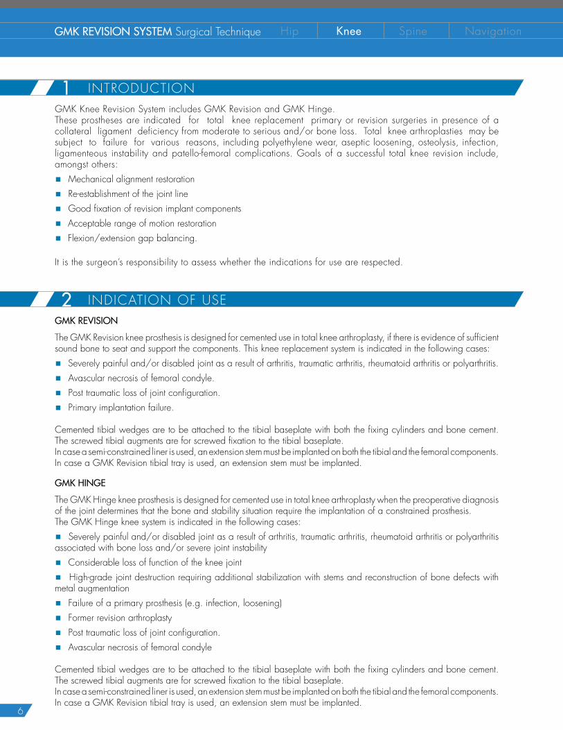
INDICATION OF USEGMK REVISION
The GMK Revision knee prosthesis is designed for cemented use in total knee arthroplasty, if there is evidence of sufficient sound bone to seat and support the components. This knee replacement system is indicated in the following cases:
� Severely painful and/or disabled joint as a result of arthritis, traumatic arthritis, rheumatoid arthritis or polyarthritis.
� Avascular necrosis of femoral condyle.
� Post traumatic loss of joint configuration.
� Primary implantation failure.
Cemented tibial wedges are to be attached to the tibial baseplate with both the fixing cylinders and bone cement. The screwed tibial augments are for screwed fixation to the tibial baseplate.In case a semi-constrained liner is used, an extension stem must be implanted on both the tibial and the femoral components. In case a GMK Revision tibial tray is used, an extension stem must be implanted.
GMK HINGE
The GMK Hinge knee prosthesis is designed for cemented use in total knee arthroplasty when the preoperative diagnosis of the joint determines that the bone and stability situation require the implantation of a constrained prosthesis.The GMK Hinge knee system is indicated in the following cases:
� Severely painful and/or disabled joint as a result of arthritis, traumatic arthritis, rheumatoid arthritis or polyarthritis associated with bone loss and/or severe joint instability
� Considerable loss of function of the knee joint
� High-grade joint destruction requiring additional stabilization with stems and reconstruction of bone defects with metal augmentation
� Failure of a primary prosthesis (e.g. infection, loosening)
� Former revision arthroplasty
� Post traumatic loss of joint configuration.
� Avascular necrosis of femoral condyle
Cemented tibial wedges are to be attached to the tibial baseplate with both the fixing cylinders and bone cement. The screwed tibial augments are for screwed fixation to the tibial baseplate.In case a semi-constrained liner is used, an extension stem must be implanted on both the tibial and the femoral components. In case a GMK Revision tibial tray is used, an extension stem must be implanted.
2
INTRODUCTIONGMK Knee Revision System includes GMK Revision and GMK Hinge.These prostheses are indicated for total knee replacement primary or revision surgeries in presence of a collateral ligament deficiency from moderate to serious and/or bone loss. Total knee arthroplasties may be subject to failure for various reasons, including polyethylene wear, aseptic loosening, osteolysis, infection, ligamenteous instability and patello-femoral complications. Goals of a successful total knee revision include, amongst others:
� Mechanical alignment restoration
� Re-establishment of the joint line
� Good fixation of revision implant components
� Acceptable range of motion restoration
� Flexion/extension gap balancing.
It is the surgeon’s responsibility to assess whether the indications for use are respected.
1
7
4
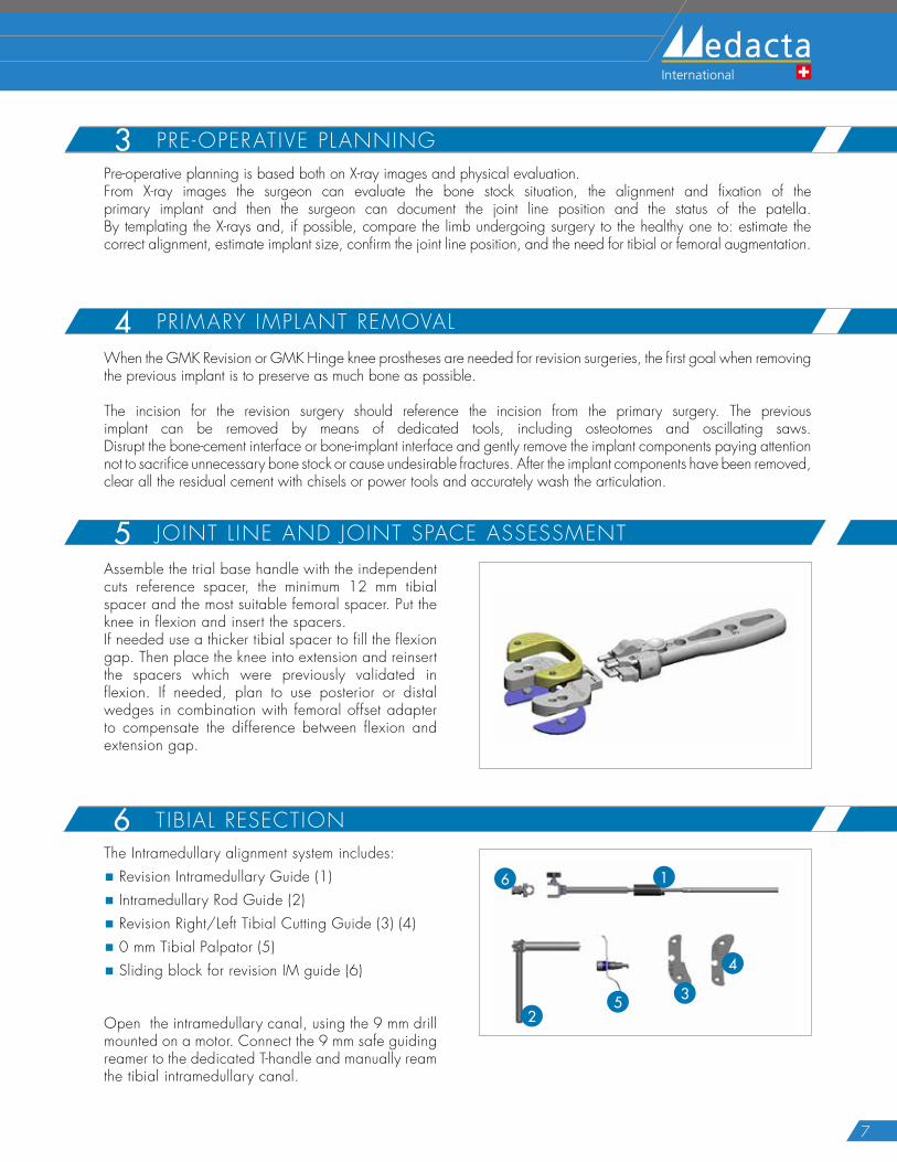
The Intramedullary alignment system includes:
� Revision Intramedullary Guide (1)
� Intramedullary Rod Guide (2)
� Revision Right/Left Tibial Cutting Guide (3) (4)
� 0 mm Tibial Palpator (5)
� Sliding block for revision IM guide (6)
Open the intramedullary canal, using the 9 mm drill mounted on a motor. Connect the 9 mm safe guiding reamer to the dedicated T-handle and manually ream the tibial intramedullary canal.
6 T IBIAL RESECTION
Assemble the trial base handle with the independent cuts reference spacer, the minimum 12 mm tibial spacer and the most suitable femoral spacer. Put the knee in flexion and insert the spacers.If needed use a thicker tibial spacer to fill the flexion gap. Then place the knee into extension and reinsert the spacers which were previously validated in flexion. If needed, plan to use posterior or distal wedges in combination with femoral offset adapter to compensate the difference between flexion and extension gap.
5 JOINT L INE AND JOINT SPACE ASSESSMENT
PRE-OPERATIVE PLANNING3Pre-operative planning is based both on X-ray images and physical evaluation.From X-ray images the surgeon can evaluate the bone stock situation, the alignment and fixation of the primary implant and then the surgeon can document the joint line position and the status of the patella. By templating the X-rays and, if possible, compare the limb undergoing surgery to the healthy one to: estimate the correct alignment, estimate implant size, confirm the joint line position, and the need for tibial or femoral augmentation.
PRIMARY IMPLANT REMOVAL4When the GMK Revision or GMK Hinge knee prostheses are needed for revision surgeries, the first goal when removing the previous implant is to preserve as much bone as possible. The incision for the revision surgery should reference the incision from the primary surgery. The previous implant can be removed by means of dedicated tools, including osteotomes and oscillating saws. Disrupt the bone-cement interface or bone-implant interface and gently remove the implant components paying attention not to sacrifice unnecessary bone stock or cause undesirable fractures. After the implant components have been removed, clear all the residual cement with chisels or power tools and accurately wash the articulation.
1
25
6
3
4
8
GMK REVISION SYSTEM Surgical Technique Hip Knee Spine Navigation
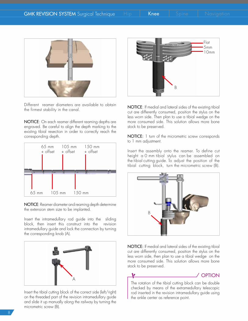
Different reamer diameters are available to obtain the firmest stability in the canal.
NOTICE: On each reamer different reaming depths are engraved. Be careful to align the depth marking to the existing tibial resection in order to correctly reach the corresponding depth.
65 mm+ offset
65 mm+
105 mm+ offset
105 mm+
150 mm+ offset
150 mm+
NOTICE: Reamer diameter and reaming depth determine the extension stem size to be implanted.
Insert the intramedullary rod guide into the sliding block, then insert this construct into the revision intramedullary guide and lock the connection by turning the corresponding knob (A).
A
Insert the tibial cutting block of the correct side (left/right) on the threaded part of the revision intramedullary guide and slide it up manually along the railway by turning the micrometric screw (B).
B
NOTICE: If medial and lateral sides of the existing tibial cut are differently consumed, position the stylus on the less worn side. Then plan to use a tibial wedge on the more consumed side. This solution allows more bone stock to be preserved.
NOTICE: 1 turn of the micrometric screw corresponds to 1 mm adjustment.
Insert the assembly onto the reamer. To define cut height a 0 mm tibial stylus can be assembled on the tibial cutting guide. To adjust the position of the tibial cutting block, turn the micrometric screw (B).
B
NOTICE: If medial and lateral sides of the existing tibial cut are differently consumed, position the stylus on the less worn side, then plan to use a tibial wedge on the more consumed side. This solution allows more bone stock to be preserved.
OPTIONThe rotation of the tibial cutting block can be double checked by means of the extramedullary telescopic rod inserted in the revision intramedullary guide using the ankle center as reference point.
Flat5mm10mm
9
Once the cutting guide position is deemed satisfactory, drill and then insert two pins in the holes row marked with a line with the help of a pin impactor.
Check the guide position with the help of the angel wings and, if necessary, reposition the guide on the pins using the correction holes (+2, +4, +6 mm). When the position of the guide is deemed satisfactory, remove the alignment system in the order below:
� Remove the tibial stylus
� Unscrew the micrometric screw
� Unlock all the knobs
� Pull up the sliding block together with the intramedullary rod guide
� Extract the intramedullary rod guide
� Extract the reamer with the T-handle
Insert the third oblique stabilization pin and finally perform the tibial cut. The cuts are based on the intramedullary reference. Once all the resections have been done, remove the cutting block and the pins.
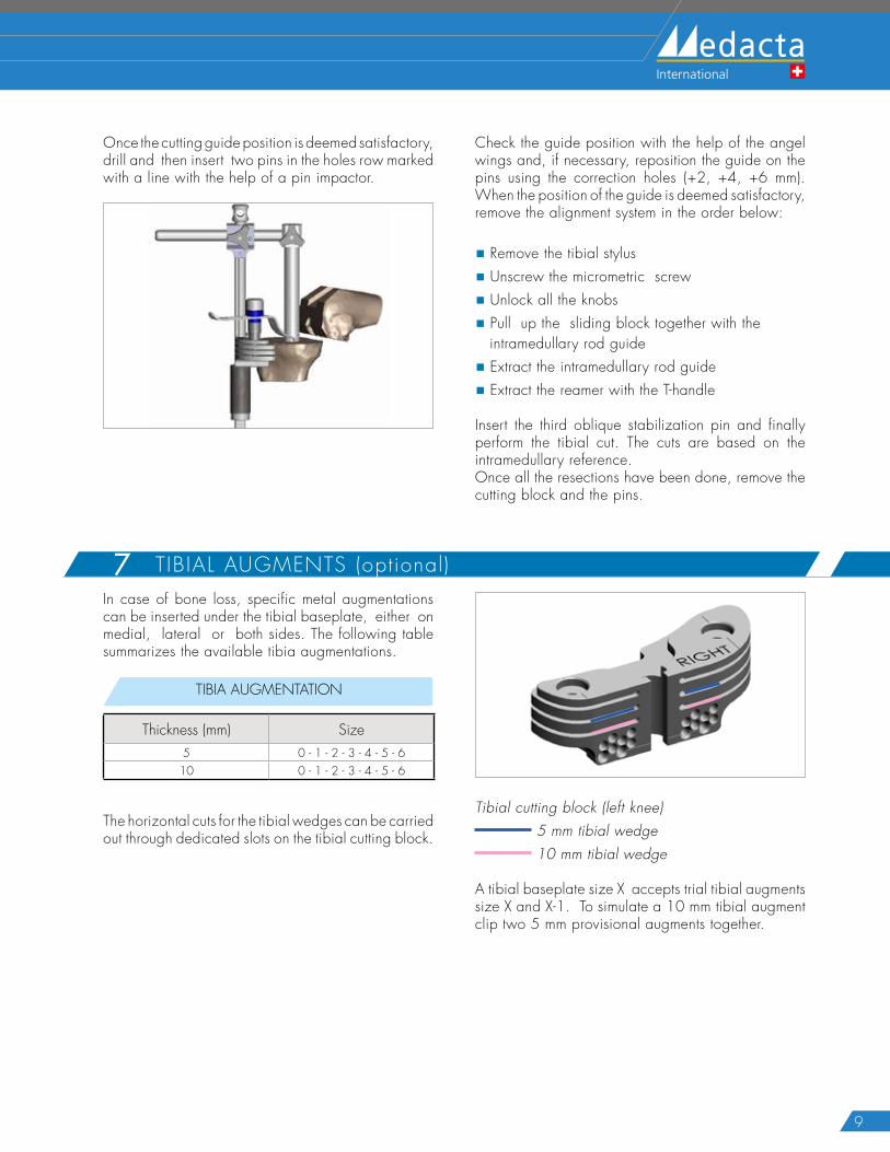
T IBIAL AUGMENTS (optional)7In case of bone loss, specific metal augmentations can be inserted under the tibial baseplate, either on medial, lateral or both sides. The following table summarizes the available tibia augmentations.
TIBIA AUGMENTATION
Thickness (mm) Size5 0 - 1 - 2 - 3 - 4 - 5 - 6
10 0 - 1 - 2 - 3 - 4 - 5 - 6
The horizontal cuts for the tibial wedges can be carried out through dedicated slots on the tibial cutting block.
Tibial cutting block (left knee) 5 mm tibial wedge 10 mm tibial wedge
A tibial baseplate size X accepts trial tibial augments size X and X-1. To simulate a 10 mm tibial augment clip two 5 mm provisional augments together.
10
GMK REVISION SYSTEM Surgical Technique Hip Knee Spine Navigation
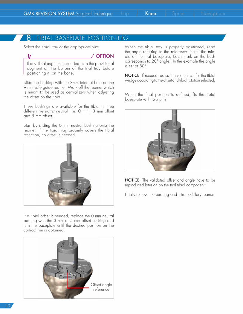
TIBIAL BASEPLATE POSITIONING 8When the tibial tray is properly positioned, read the angle referring to the reference line in the mid-dle of the trial baseplate. Each mark on the bush corresponds to 20° angle. In the example the angle is set at 80°.
NOTICE: If needed, adjust the vertical cut for the tibial wedge according to the offset and tibial rotation selected.
When the final position is defined, fix the tibial baseplate with two pins.
NOTICE: The validated offset and angle have to be reproduced later on on the trial tibial component.
Finally remove the bushing and intramedullary reamer.
Select the tibial tray of the appropriate size.
OPTIONIf any tibial augment is needed, clip the provisional augment on the bottom of the trial tray before positioning it on the bone.
Slide the bushing with the 8mm internal hole on the 9 mm safe guide reamer. Work off the reamer which is meant to be used as centralizers when adjusting the offset on the tibia.
These bushings are available for the tibia in three different versions: neutral (i.e. 0 mm), 3 mm offset and 5 mm offset.
Start by sliding the 0 mm neutral bushing onto the reamer. If the tibial tray properly covers the tibial resection, no offset is needed.
If a tibial offset is needed, replace the 0 mm neutral bushing with the 3 mm or 5 mm offset bushing and turn the baseplate until the desired position on the cortical rim is obtained.
Offset angle reference
11
TIBIA FINISHING9The bushings with 15.5 mm internal hole are meant to finish the preparation of the tibia to create room for the offset coupler and for the stem connection, where needed.
OPTIONWhen a 3 or 5mm offset coupler is necessary for correct placement of the tibial tray, room must be created for the component using the 15.5mm reamer. Insert the neutral bushing (i.e. 0 mm) into the fixed tibial baseplate. Using two fingers hold the bushing firmly and ream with the 15.5 mm, to the step off.
Stop here
NOTICE: This step is not needed when implanting GMK Hinge even if an offset coupler is used.
OPTIONIf the intramedually canal is prepared with a 15mm or smaller reamer, room must be created for the component. Insert the 3 or 5mm bushing into the fixed tibial baseplate. Rotate the bushing until the correct angle is achieved. Using two fingers hold the bushing firmly and ream with the 15.5mm reamer.
Stop here
CAUTIONThe rotation of the bush is relevant at this stage.
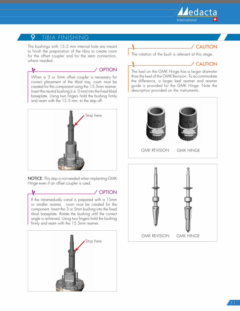
CAUTIONThe keel on the GMK Hinge has a larger diameter than the keel of the GMK Revision. To accommodate the difference, a larger keel reamer and reamer guide is provided for the GMK Hinge. Note the description provided on the instruments.
GMK REVISION GMK HINGE
GMK REVISION GMK HINGE
12
GMK REVISION SYSTEM Surgical Technique Hip Knee Spine Navigation
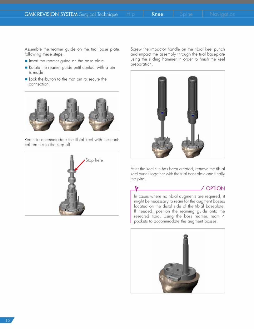
T IBIAL OFFSET DEFINITION (option)8Assemble the reamer guide on the trial base plate following these steps:
� Insert the reamer guide on the base plate
� Rotate the reamer guide until contact with a pin is made
� Lock the button to the that pin to secure the connection.
Ream to accommodate the tibial keel with the coni-cal reamer to the step off.
Stop here
Screw the impactor handle on the tibial keel punch and impact the assembly through the trial baseplate using the sliding hammer in order to finish the keel preparation.
After the keel site has been created, remove the tibial keel punch together with the trial baseplate and finally the pins.
OPTIONIn cases where no tibial augments are required, it might be necessary to ream for the augment bosses located on the distal side of the tibial baseplate. If needed, position the reaming guide onto the resected tibia. Using the boss reamer, ream 4 pockets to accommodate the augment bosses.
13
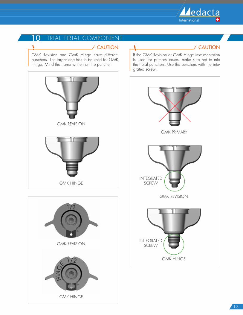
CAUTIONGMK Revision and GMK Hinge have different punchers. The larger one has to be used for GMK Hinge. Mind the name written on the puncher.
GMK REVISION
GMK HINGE
CAUTIONIf the GMK Revision or GMK Hinge instrumentation is used for primary cases, make sure not to mix the tibial punchers. Use the punchers with the inte-grated screw.
GMK REVISION
GMK PRIMARY
GMK HINGE
INTEGRATEDSCREW
INTEGRATEDSCREW
TRIAL TIBIAL COMPONENT 10
GMK REVISION
GMK HINGE
14
GMK REVISION SYSTEM Surgical Technique Hip Knee Spine Navigation
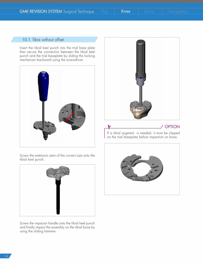
OPTIONIf a tibial augment is needed, it must be clipped on the trial baseplate before impaction on bone.
T IBIAL OFFSET DEFINITION (option)810.1 Tibia without offset
Insert the tibial keel punch into the trial base plate then secure the connection between the tibial keel punch and the trial baseplate by sliding the locking mechanism backward using the screwdriver.
Screw the extension stem of the correct size onto the tibial keel punch.
Screw the impactor handle onto the tibial keel punch and finally impact the assembly on the tibial bone by using the sliding hammer.
15
10.2 3 mm or 5 mm tibial offset
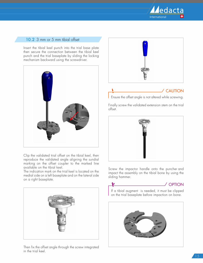
Insert the tibial keel punch into the trial base plate then secure the connection between the tibial keel punch and the trial baseplate by sliding the locking mechanism backward using the screwdriver.
Clip the validated trial offset on the tibial keel, then reproduce the validated angle aligning the sundial marking on the offset coupler to the marked line available on the tibial keel.The indication mark on the trial keel is located on the medial side on a left baseplate and on the lateral side on a right baseplate.
Then fix the offset angle through the screw integrated in the trial keel.
CAUTIONEnsure the offset angle is not altered while screwing.
Finally screw the validated extension stem on the trial offset.
Screw the impactor handle onto the puncher and impact the assembly on the tibial bone by using the sliding hammer.
OPTIONIf a tibial augment is needed, it must be clipped on the trial baseplate before impaction on bone.
16
GMK REVISION SYSTEM Surgical Technique Hip Knee Spine Navigation
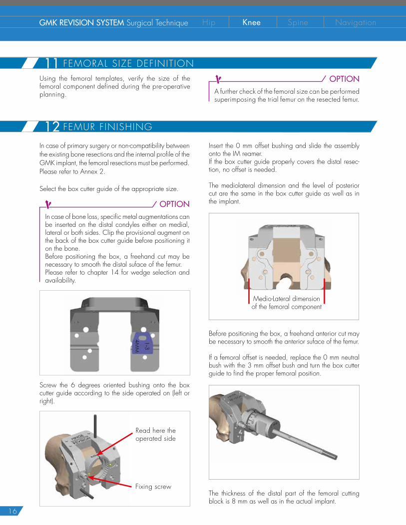
Using the femoral templates, verify the size of the femoral component defined during the pre-operative planning.
In case of primary surgery or non-compatibility between the existing bone resections and the internal profile of the GMK implant, the femoral resections must be performed. Please refer to Annex 2.
Select the box cutter guide of the appropriate size.
OPTIONIn case of bone loss, specific metal augmentations can be inserted on the distal condyles either on medial, lateral or both sides. Clip the provisional augment on the back of the box cutter guide before positioning it on the bone.Before positioning the box, a freehand cut may be necessary to smooth the distal suface of the femur.Please refer to chapter 14 for wedge selection and availability.
Screw the 6 degrees oriented bushing onto the box cutter guide according to the side operated on (left or right).
Read here the operated side
Fixing screw
OPTIONA further check of the femoral size can be performed superimposing the trial femur on the resected femur.
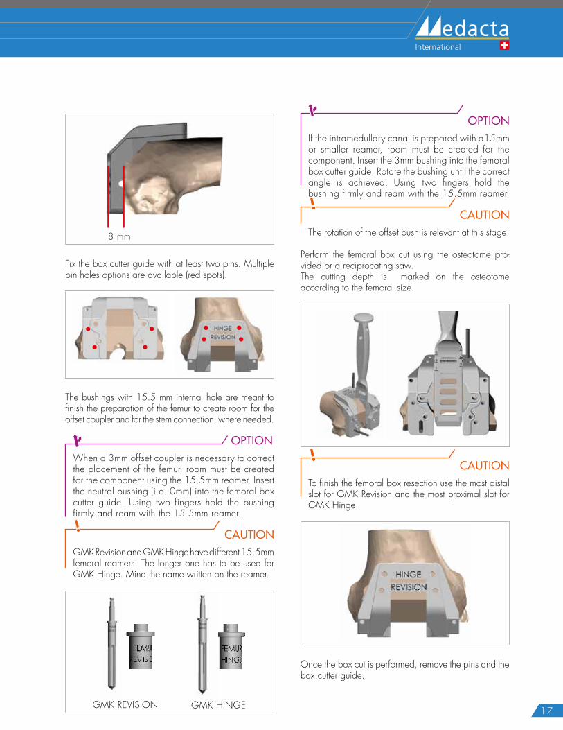
Insert the 0 mm offset bushing and slide the assembly onto the IM reamer.If the box cutter guide properly covers the distal resec-tion, no offset is needed.
The mediolateral dimension and the level of posterior cut are the same in the box cutter guide as well as in the implant.
Medio-Lateral dimensionof the femoral component
Before positioning the box, a freehand anterior cut may be necessary to smooth the anterior suface of the femur.
If a femoral offset is needed, replace the 0 mm neutral bush with the 3 mm offset bush and turn the box cutter guide to find the proper femoral position.
The thickness of the distal part of the femoral cutting block is 8 mm as well as in the actual implant.
11 FEMORAL SIZE DEFINIT ION
12 FEMUR F INISHING
17
8 mm
Fix the box cutter guide with at least two pins. Multiple pin holes options are available (red spots).
The bushings with 15.5 mm internal hole are meant to finish the preparation of the femur to create room for the offset coupler and for the stem connection, where needed.
OPTIONWhen a 3mm offset coupler is necessary to correct the placement of the femur, room must be created for the component using the 15.5mm reamer. Insert the neutral bushing (i.e. 0mm) into the femoral box cutter guide. Using two fingers hold the bushing firmly and ream with the 15.5mm reamer.
CAUTIONGMK Revision and GMK Hinge have different 15.5mm femoral reamers. The longer one has to be used for GMK Hinge. Mind the name written on the reamer.
GMK REVISION GMK HINGE
OPTIONIf the intramedullary canal is prepared with a15mm or smaller reamer, room must be created for the component. Insert the 3mm bushing into the femoral box cutter guide. Rotate the bushing until the correct angle is achieved. Using two fingers hold the bushing firmly and ream with the 15.5mm reamer.
CAUTIONThe rotation of the offset bush is relevant at this stage.
Perform the femoral box cut using the osteotome pro-vided or a reciprocating saw.The cutting depth is marked on the osteotome according to the femoral size.
CAUTIONTo finish the femoral box resection use the most distal slot for GMK Revision and the most proximal slot for GMK Hinge.
Once the box cut is performed, remove the pins and the box cutter guide.
18
GMK REVISION SYSTEM Surgical Technique Hip Knee Spine Navigation
OPTIONIf a distal augment is needed, clip the validated provisional distal augment on the correct side of the trial femoral component, medial or lateral.
Position the assembly on the femur using the slide hammer and the femoral impactor.
CAUTION
In case of impingement between the trial box and the internal rim of the medial condyle during trial femoral implant insertion, enlarge the medial side of the femoral box by using an osteotome.
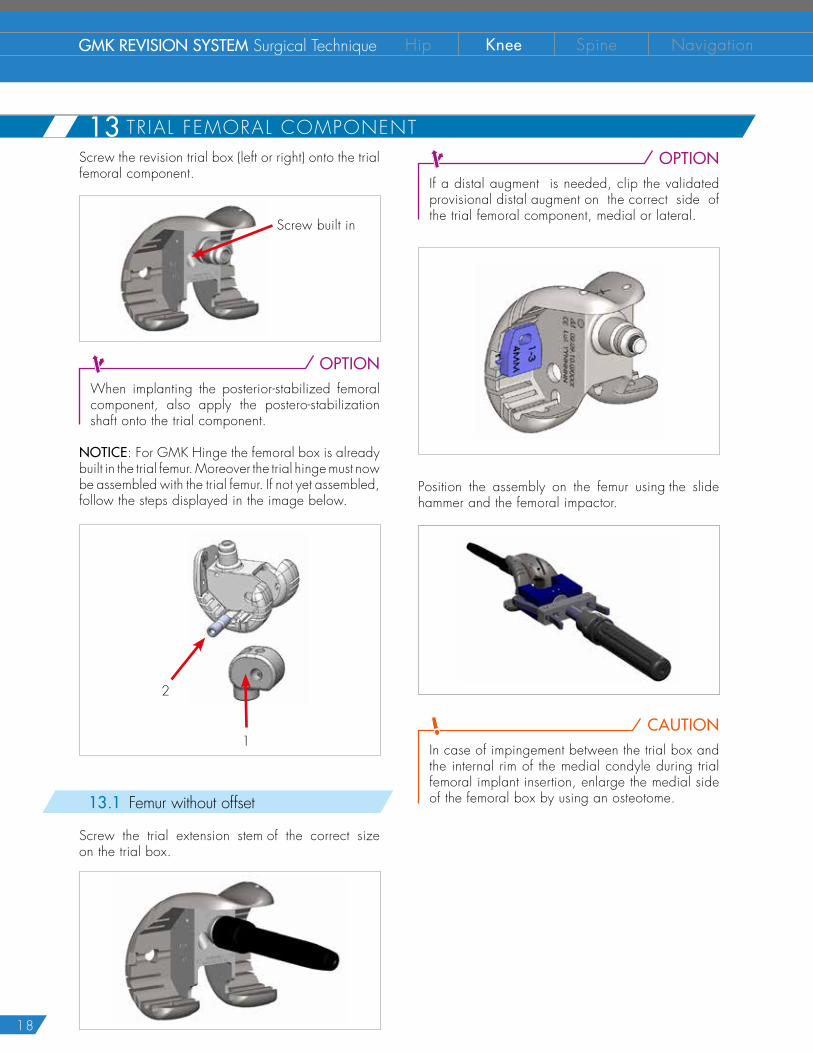
Screw the revision trial box (left or right) onto the trial femoral component.
Screw built in
OPTIONWhen implanting the posterior-stabilized femoral component, also apply the postero-stabilization shaft onto the trial component.
NOTICE: For GMK Hinge the femoral box is already built in the trial femur. Moreover the trial hinge must now be assembled with the trial femur. If not yet assembled, follow the steps displayed in the image below.
1
2
13.1 Femur without offset
Screw the trial extension stem of the correct size on the trial box.
13 TRIAL FEMORAL COMPONENT
19
21 FEMORAL BOX PREPARATION
22 TRIAL FEMORAL COMPONENT (no femoral of f se t )
13.2 3 mm offset option
Before impacting the trial femoral component, the offset previously validated must be reproduced.
CAUTIONThe 5 mm offset is not allowed for the femur.
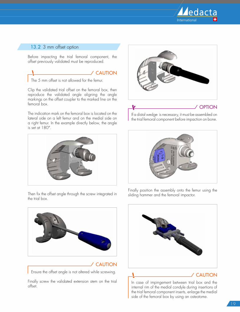
Clip the validated trial offset on the femoral box, then reproduce the validated angle aligning the angle markings on the offset coupler to the marked line on the femoral box.
The indication mark on the femoral box is located on the lateral side on a left femur and on the medial side on a right femur. In the example directly below, the angle is set at 180°.
Then fix the offset angle through the screw integrated in the trial box.
CAUTION
Ensure the offset angle is not altered while screwing.
Finally screw the validated extension stem on the trial offset.
OPTIONIf a distal wedge is necessary, it must be assembled on the trial femoral component before impaction on bone.
Finally position the assembly onto the femur using the sliding hammer and the femoral impactor.
CAUTIONIn case of impingement between trial box and the internal rim of the medial condyle during insertions of the trial femoral component inserts, enlarge the medial side of the femoral box by using an osteotome.
20
GMK REVISION SYSTEM Surgical Technique Hip Knee Spine Navigation
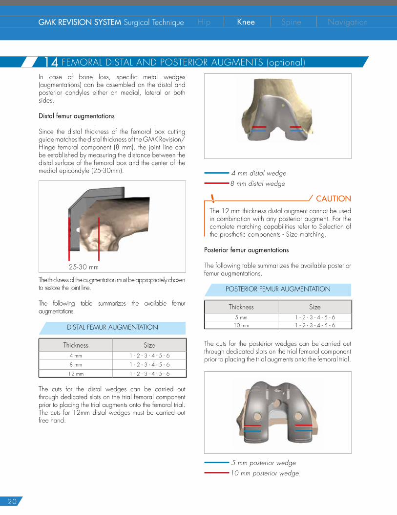
In case of bone loss, specific metal wedges (augmentations) can be assembled on the distal and posterior condyles either on medial, lateral or both sides.
Distal femur augmentations
Since the distal thickness of the femoral box cutting guide matches the distal thickness of the GMK Revision/Hinge femoral component (8 mm), the joint line can be established by measuring the distance between the distal surface of the femoral box and the center of the medial epicondyle (25-30mm).
25-30 mm
The thickness of the augmentation must be appropriately chosen to restore the joint line.
The following table summarizes the available femur augmentations.
DISTAL FEMUR AUGMENTATION
Thickness Size4 mm 1 - 2 - 3 - 4 - 5 - 6
8 mm 1 - 2 - 3 - 4 - 5 - 6
12 mm 1 - 2 - 3 - 4 - 5 - 6
The cuts for the distal wedges can be carried out through dedicated slots on the trial femoral component prior to placing the trial augments onto the femoral trial. The cuts for 12mm distal wedges must be carried out free hand.
4 mm distal wedge 8 mm distal wedge
CAUTIONThe 12 mm thickness distal augment cannot be used in combination with any posterior augment. For the complete matching capabilities refer to Selection of the prosthetic components - Size matching.
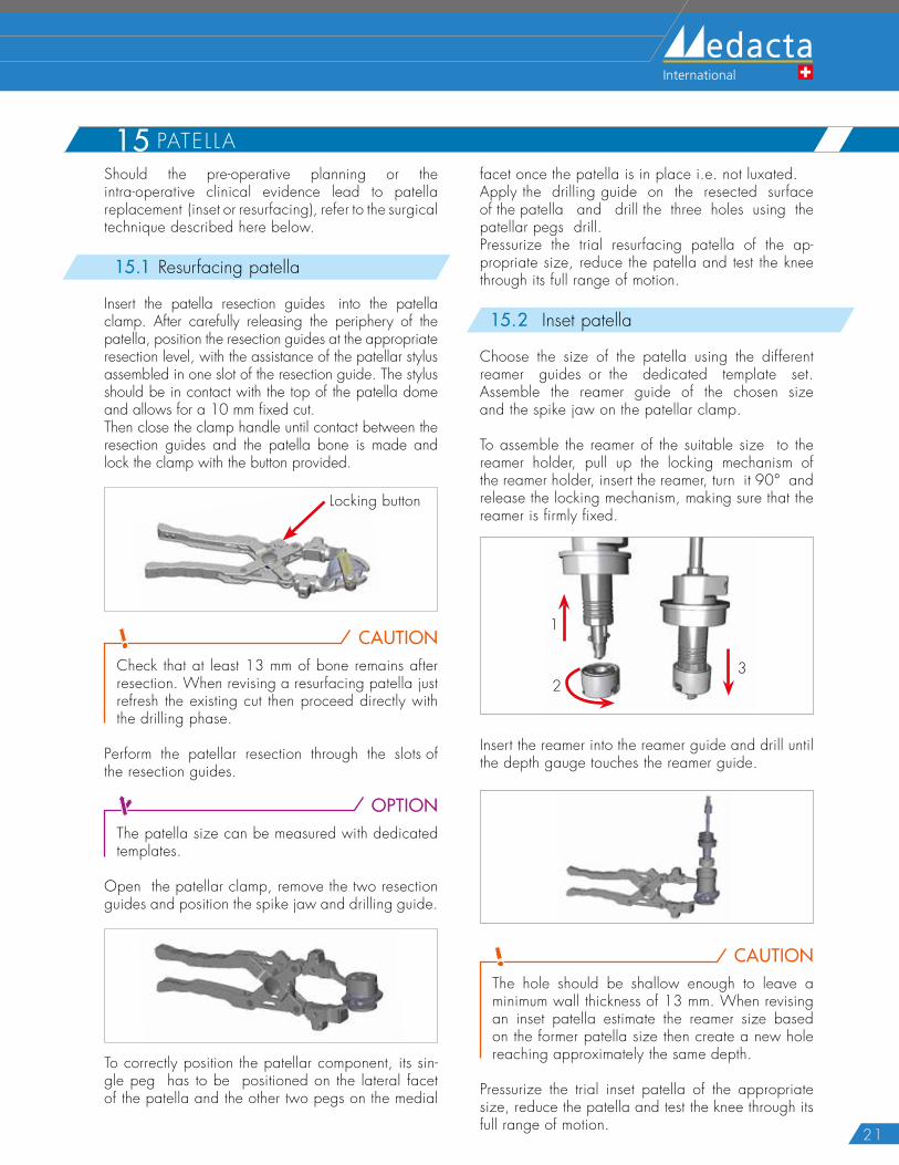
Posterior femur augmentations
The following table summarizes the available posterior femur augmentations.
POSTERIOR FEMUR AUGMENTATION
Thickness Size5 mm 1 - 2 - 3 - 4 - 5 - 610 mm 1 - 2 - 3 - 4 - 5 - 6
The cuts for the posterior wedges can be carried out through dedicated slots on the trial femoral component prior to placing the trial augments onto the femoral trial.
5 mm posterior wedge 10 mm posterior wedge
14 FEMORAL DISTAL AND POSTERIOR AUGMENTS (optional)
21
15 PATELLAShould the pre-operative planning or the intra-operative clinical evidence lead to patella replacement (inset or resurfacing), refer to the surgical technique described here below.
15.1 Resurfacing patella
Insert the patella resection guides into the patella clamp. After carefully releasing the periphery of the patella, position the resection guides at the appropriate resection level, with the assistance of the patellar stylus assembled in one slot of the resection guide. The stylus should be in contact with the top of the patella dome and allows for a 10 mm fixed cut.Then close the clamp handle until contact between the resection guides and the patella bone is made and lock the clamp with the button provided.
Locking button
CAUTIONCheck that at least 13 mm of bone remains after resection. When revising a resurfacing patella just refresh the existing cut then proceed directly with the drilling phase.
Perform the patellar resection through the slots of the resection guides.
OPTIONThe patella size can be measured with dedicated templates.
Open the patellar clamp, remove the two resection guides and position the spike jaw and drilling guide.
To correctly position the patellar component, its sin-gle peg has to be positioned on the lateral facet of the patella and the other two pegs on the medial
facet once the patella is in place i.e. not luxated.Apply the drilling guide on the resected surface of the patella and drill the three holes using the patellar pegs drill. Pressurize the trial resurfacing patella of the ap-propriate size, reduce the patella and test the knee through its full range of motion.
15.2 Inset patella
Choose the size of the patella using the different reamer guides or the dedicated template set. Assemble the reamer guide of the chosen size and the spike jaw on the patellar clamp.
To assemble the reamer of the suitable size to the reamer holder, pull up the locking mechanism of the reamer holder, insert the reamer, turn it 90° and release the locking mechanism, making sure that the reamer is firmly fixed.
1
23
Insert the reamer into the reamer guide and drill until the depth gauge touches the reamer guide.
CAUTIONThe hole should be shallow enough to leave a minimum wall thickness of 13 mm. When revising an inset patella estimate the reamer size based on the former patella size then create a new hole reaching approximately the same depth.
Pressurize the trial inset patella of the appropriate size, reduce the patella and test the knee through its full range of motion.
22
GMK REVISION SYSTEM Surgical Technique Hip Knee Spine Navigation
16 TR IAL IMPLANT EVALUATION16.1 GMK Revision
OPTIONWhen implanting the posterior-stabilized femur apply the posterior-stabilization shaft on the trial femur.
Put the proper trial insert of the appropriate size and thickness into the trial baseplate.
Once the trial components are in place reduce the patella and test the knee through its full range of motion.
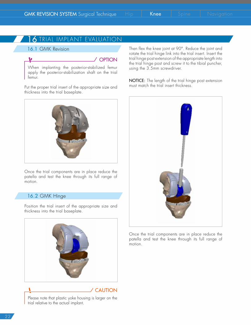
16.2 GMK Hinge
Position the trial insert of the appropriate size and thickness into the trial baseplate.
CAUTIONPlease note that plastic yoke housing is larger on the trial relative to the actual implant.
Then flex the knee joint at 90°. Reduce the joint and rotate the trial hinge link into the trial insert. Insert the trial hinge post extension of the appropriate length into the trial hinge post and screw it to the tibial puncher, using the 3.5mm screwdriver.
NOTICE: The length of the trial hinge post extension must match the trial insert thickness.
Once the trial components are in place reduce the patella and test the knee through its full range of motion.
23
17 F INAL T IB IAL IMPLANT ASSEMBLY CAUTION
Before assembling the final implant verify that all the connection surfaces (threaded and tapered) are clean and dry. It is suggested to change the surgical gloves with clean ones before assembling the final implant. Be careful not to damage the articular surfaces while assembling the final implant.
17.1 Tibia without offset
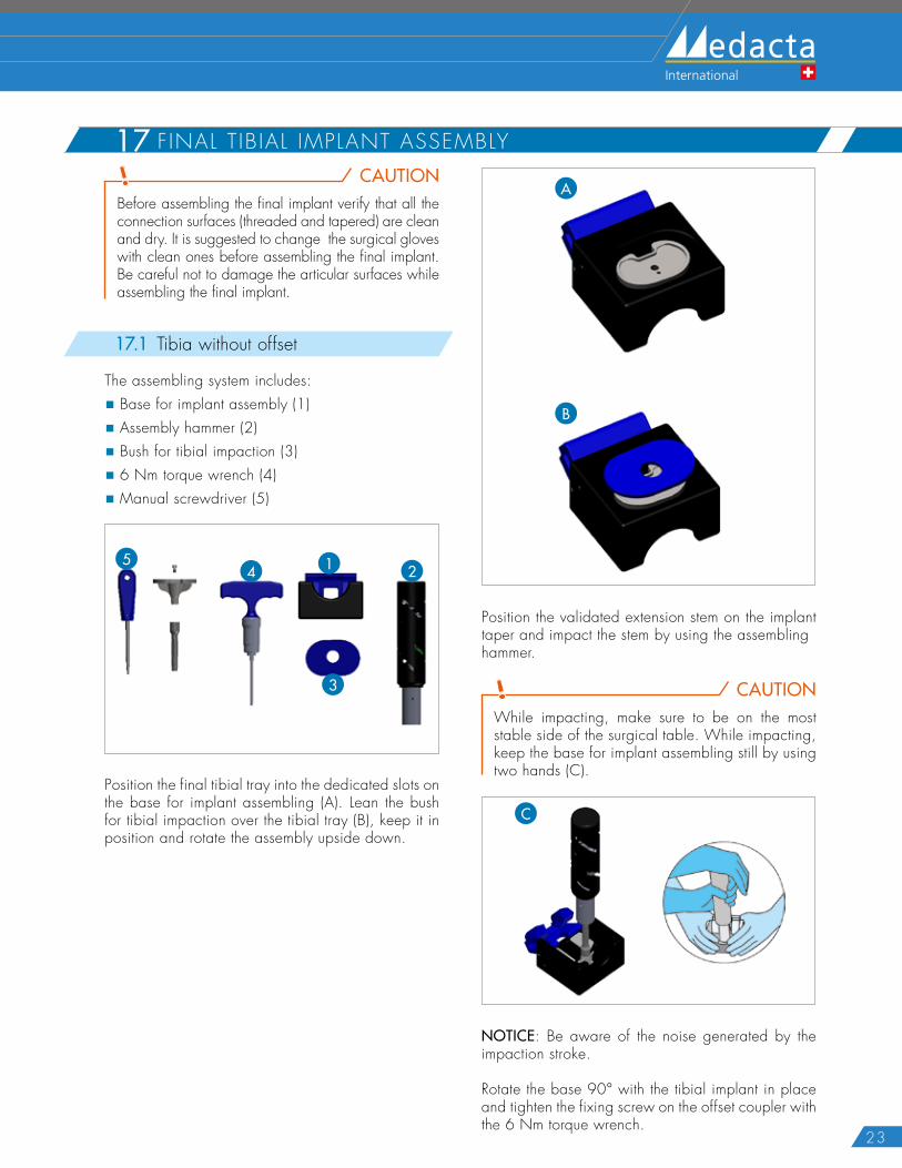
The assembling system includes:
� Base for implant assembly (1)
� Assembly hammer (2)
� Bush for tibial impaction (3)
� 6 Nm torque wrench (4)
� Manual screwdriver (5)
1 25
4
3
Position the final tibial tray into the dedicated slots on the base for implant assembling (A). Lean the bush for tibial impaction over the tibial tray (B), keep it in position and rotate the assembly upside down.
A
B
Position the validated extension stem on the implant taper and impact the stem by using the assembling hammer.
CAUTIONWhile impacting, make sure to be on the most stable side of the surgical table. While impacting, keep the base for implant assembling still by using two hands (C).
C
NOTICE: Be aware of the noise generated by the impaction stroke.
Rotate the base 90° with the tibial implant in place and tighten the fixing screw on the offset coupler with the 6 Nm torque wrench.
24
GMK REVISION SYSTEM Surgical Technique Hip Knee Spine Navigation
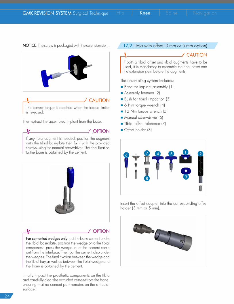
NOTICE: The screw is packaged with the extension stem.
CAUTIONThe correct torque is reached when the torque limiter is released.
Then extract the assembled implant from the base.
OPTIONIf any tibial augment is needed, position the augment onto the tibial baseplate then fix it with the provided screws using the manual screwdriver. The final fixation to the bone is obtained by the cement.
OPTIONFor cemented wedges only: put the bone cement under the tibial baseplate, position the wedge onto the tibial component, press the wedge to let the cement come out from the interface. Then put the cement also under the wedges. The final fixation between the wedge andthe tibial tray as well as between the tibial wedge andthe bone is obtained by the cement.
Finally impact the prosthetic components on the tibia and carefully clear the extruded cement from the bone, ensuring that no cement part remains on the articular surface.
17.2 Tibia with offset (3 mm or 5 mm option)
CAUTIONIf both a tibial offset and tibial augments have to be used, it is mandatory to assemble the final offset and the extension stem before the augments.
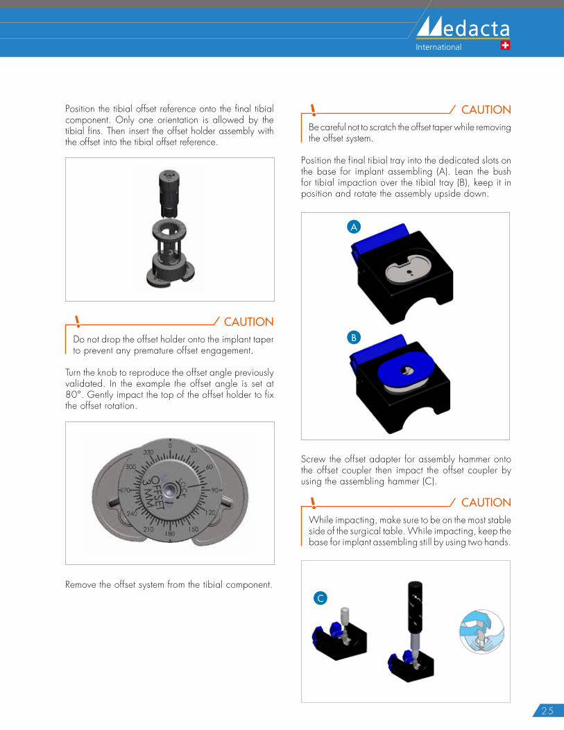
The assembling system includes:
� Base for implant assembly (1)
� Assembly hammer (2)
� Bush for tibial impaction (3)
� 6 Nm torque wrench (4)
� 12 Nm torque wrench (5)
� Manual screwdriver (6)
� Tibial offset reference (7)
� Offset holder (8)
1 256 47
38
Insert the offset coupler into the corresponding offset holder (3 mm or 5 mm).
25
Position the tibial offset reference onto the final tibial component. Only one orientation is allowed by the tibial fins. Then insert the offset holder assembly with the offset into the tibial offset reference.
CAUTIONDo not drop the offset holder onto the implant taper to prevent any premature offset engagement.
Turn the knob to reproduce the offset angle previously validated. In the example the offset angle is set at 80°. Gently impact the top of the offset holder to fix the offset rotation.
Remove the offset system from the tibial component.
CAUTIONBe careful not to scratch the offset taper while removing the offset system.
Position the final tibial tray into the dedicated slots on the base for implant assembling (A). Lean the bush for tibial impaction over the tibial tray (B), keep it in position and rotate the assembly upside down.
A
B
Screw the offset adapter for assembly hammer onto the offset coupler then impact the offset coupler by using the assembling hammer (C).
CAUTIONWhile impacting, make sure to be on the most stable side of the surgical table. While impacting, keep the base for implant assembling still by using two hands.
C
26
GMK REVISION SYSTEM Surgical Technique Hip Knee Spine Navigation
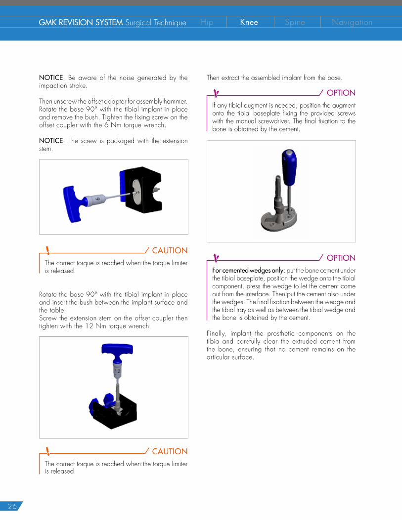
NOTICE: Be aware of the noise generated by the impaction stroke.
Then unscrew the offset adapter for assembly hammer. Rotate the base 90° with the tibial implant in place and remove the bush. Tighten the fixing screw on the offset coupler with the 6 Nm torque wrench.
NOTICE: The screw is packaged with the extension stem.
CAUTIONThe correct torque is reached when the torque limiter is released.
Rotate the base 90° with the tibial implant in place and insert the bush between the implant surface and the table. Screw the extension stem on the offset coupler then tighten with the 12 Nm torque wrench.
CAUTIONThe correct torque is reached when the torque limiter is released.
Then extract the assembled implant from the base.
OPTIONIf any tibial augment is needed, position the augment onto the tibial baseplate fixing the provided screws with the manual screwdriver. The final fixation to the bone is obtained by the cement.
OPTIONFor cemented wedges only: put the bone cement under the tibial baseplate, position the wedge onto the tibial component, press the wedge to let the cement come out from the interface. Then put the cement also under the wedges. The final fixation between the wedge andthe tibial tray as well as between the tibial wedge andthe bone is obtained by the cement.
Finally, implant the prosthetic components on the tibia and carefully clear the extruded cement from the bone, ensuring that no cement remains on the articular surface.
27
18 F INAL FEMORAL IMPLANT ASSEMBLY18.1 Femur without of fset
CAUTIONIf femoral augments are to be used, it is mandatory to assemble the extension stem before the augments.
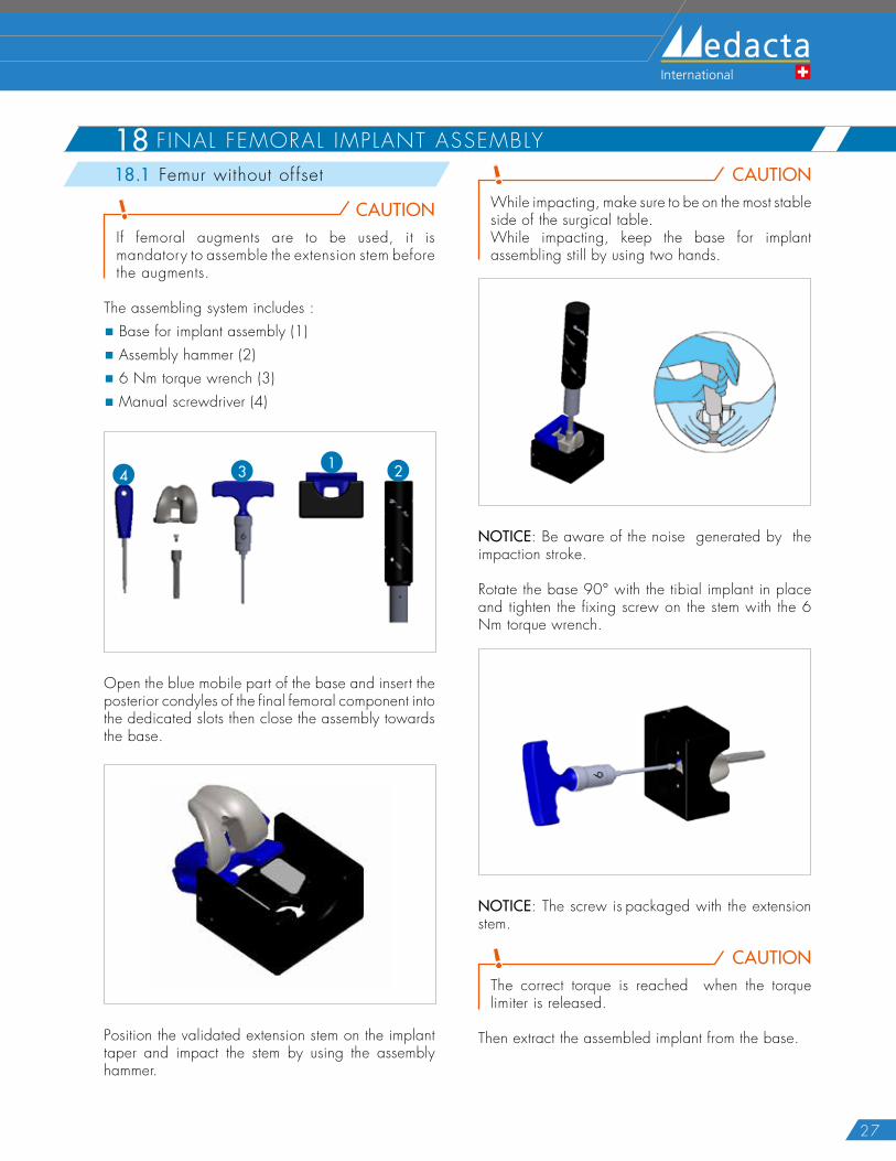
The assembling system includes :
� Base for implant assembly (1)
� Assembly hammer (2)
� 6 Nm torque wrench (3)
� Manual screwdriver (4)
1 24 3
Open the blue mobile part of the base and insert the posterior condyles of the final femoral component into the dedicated slots then close the assembly towards the base.
Position the validated extension stem on the implant taper and impact the stem by using the assembly hammer.
CAUTIONWhile impacting, make sure to be on the most stable side of the surgical table. While impacting, keep the base for implant assembling still by using two hands.
NOTICE: Be aware of the noise generated by the impaction stroke.
Rotate the base 90° with the tibial implant in place and tighten the fixing screw on the stem with the 6 Nm torque wrench.
NOTICE: The screw is packaged with the extension stem.
CAUTIONThe correct torque is reached when the torque limiter is released.
Then extract the assembled implant from the base.
28
GMK REVISION SYSTEM Surgical Technique Hip Knee Spine Navigation
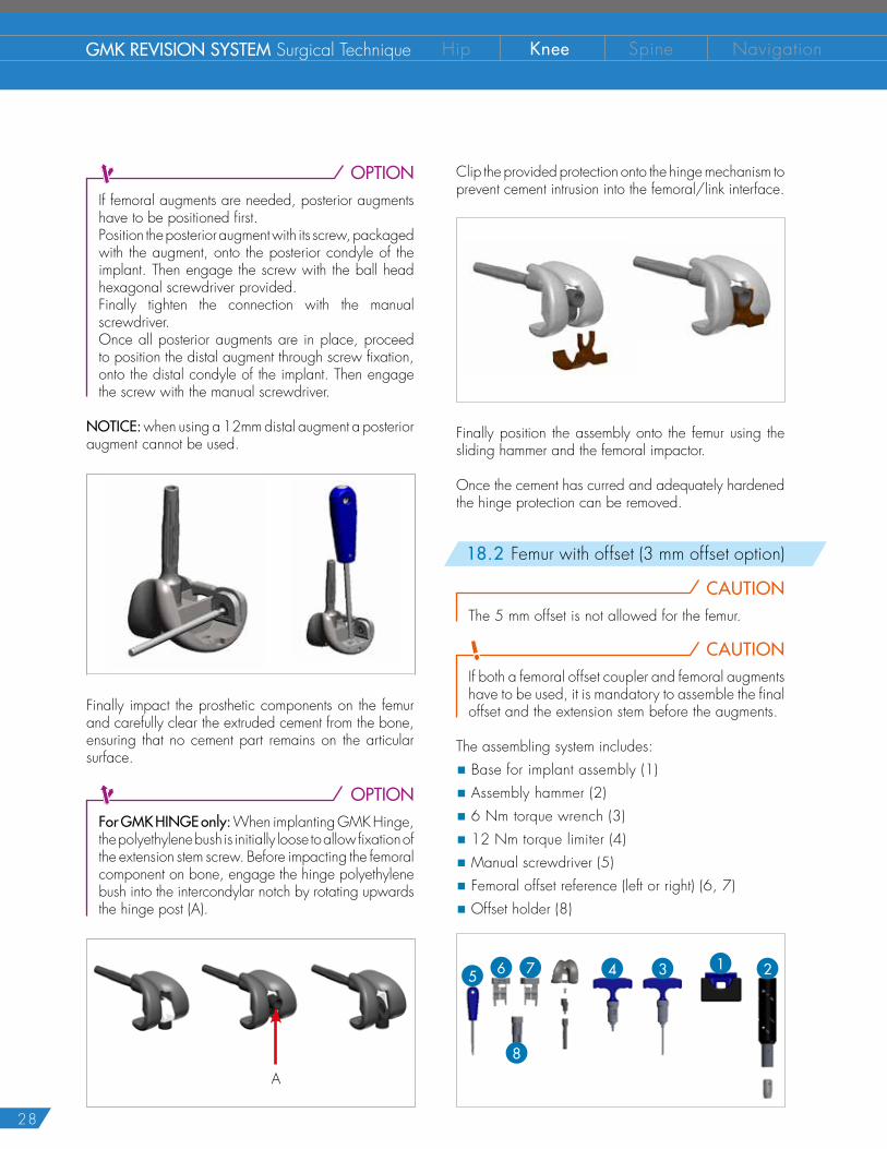
OPTIONIf femoral augments are needed, posterior augments have to be positioned first.Position the posterior augment with its screw, packaged with the augment, onto the posterior condyle of the implant. Then engage the screw with the ball head hexagonal screwdriver provided. Finally tighten the connection with the manual screwdriver.Once all posterior augments are in place, proceed to position the distal augment through screw fixation, onto the distal condyle of the implant. Then engage the screw with the manual screwdriver.
NOTICE: when using a 12mm distal augment a posterior augment cannot be used.
Finally impact the prosthetic components on the femur and carefully clear the extruded cement from the bone, ensuring that no cement part remains on the articular surface.
OPTIONFor GMK HINGE only: When implanting GMK Hinge, the polyethylene bush is initially loose to allow fixation of the extension stem screw. Before impacting the femoral component on bone, engage the hinge polyethylene bush into the intercondylar notch by rotating upwards the hinge post (A).
A
Clip the provided protection onto the hinge mechanism to prevent cement intrusion into the femoral/link interface.
Finally position the assembly onto the femur using the sliding hammer and the femoral impactor.
Once the cement has curred and adequately hardened the hinge protection can be removed.
18.2 Femur with offset (3 mm offset option)
CAUTIONThe 5 mm offset is not allowed for the femur.
CAUTIONIf both a femoral offset coupler and femoral augments have to be used, it is mandatory to assemble the final offset and the extension stem before the augments.
The assembling system includes:
� Base for implant assembly (1)
� Assembly hammer (2)
� 6 Nm torque wrench (3)
� 12 Nm torque limiter (4)
� Manual screwdriver (5)
� Femoral offset reference (left or right) (6, 7)
� Offset holder (8)
1 25 6 47 3
8
29
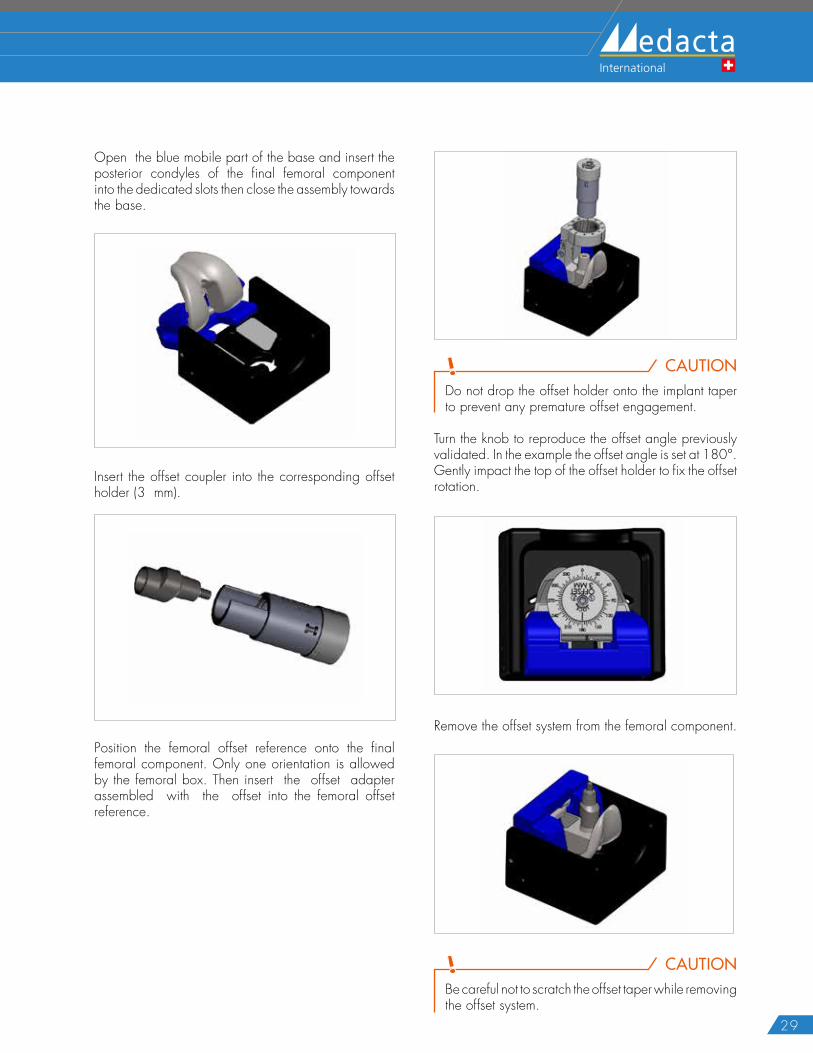
Open the blue mobile part of the base and insert the posterior condyles of the final femoral component into the dedicated slots then close the assembly towards the base.
Insert the offset coupler into the corresponding offset holder (3 mm).
Position the femoral offset reference onto the final femoral component. Only one orientation is allowed by the femoral box. Then insert the offset adapter assembled with the offset into the femoral offset reference.
CAUTIONDo not drop the offset holder onto the implant taper to prevent any premature offset engagement.
Turn the knob to reproduce the offset angle previously validated. In the example the offset angle is set at 180°. Gently impact the top of the offset holder to fix the offset rotation.
Remove the offset system from the femoral component.
CAUTIONBe careful not to scratch the offset taper while removing the offset system.
30
GMK REVISION SYSTEM Surgical Technique Hip Knee Spine Navigation
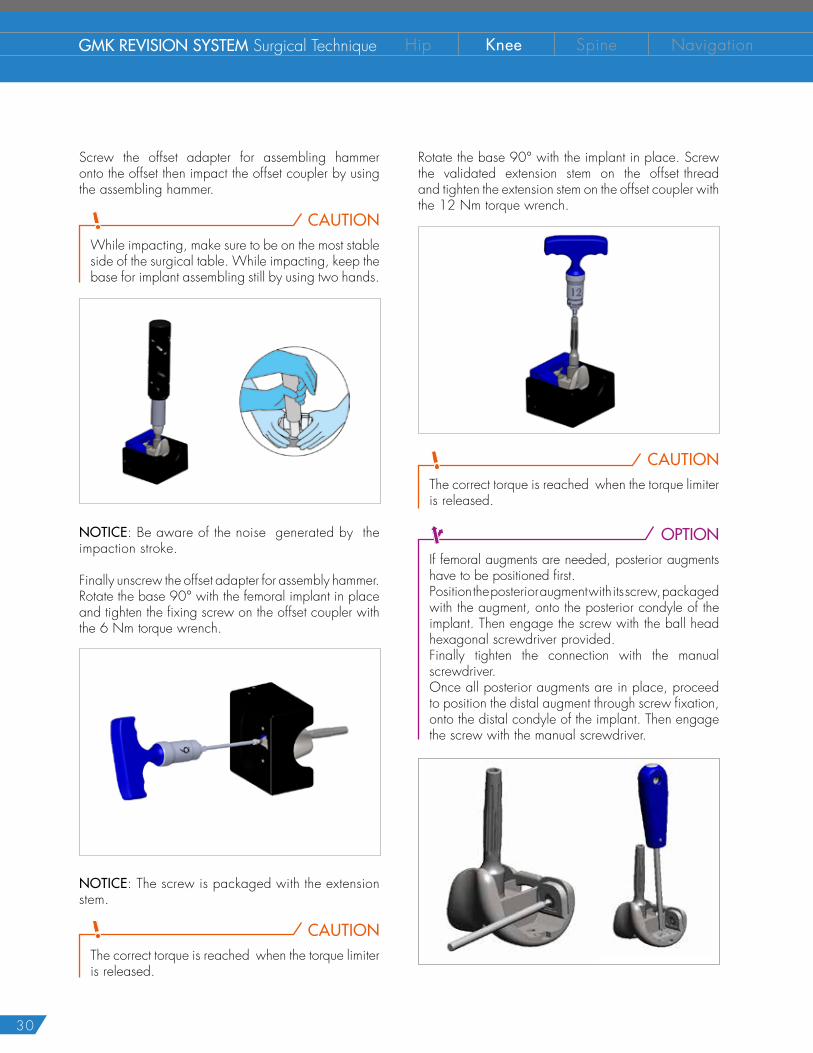
Screw the offset adapter for assembling hammer onto the offset then impact the offset coupler by using the assembling hammer.
CAUTIONWhile impacting, make sure to be on the most stable side of the surgical table. While impacting, keep the base for implant assembling still by using two hands.
NOTICE: Be aware of the noise generated by the impaction stroke.
Finally unscrew the offset adapter for assembly hammer.Rotate the base 90° with the femoral implant in place and tighten the fixing screw on the offset coupler with the 6 Nm torque wrench.
NOTICE: The screw is packaged with the extension stem.
CAUTIONThe correct torque is reached when the torque limiter is released.
Rotate the base 90° with the implant in place. Screw the validated extension stem on the offset thread and tighten the extension stem on the offset coupler with the 12 Nm torque wrench.
CAUTIONThe correct torque is reached when the torque limiter is released.
OPTIONIf femoral augments are needed, posterior augments have to be positioned first.Position the posterior augment with its screw, packaged with the augment, onto the posterior condyle of the implant. Then engage the screw with the ball head hexagonal screwdriver provided. Finally tighten the connection with the manual screwdriver.Once all posterior augments are in place, proceed to position the distal augment through screw fixation, onto the distal condyle of the implant. Then engage the screw with the manual screwdriver.
31
Finally impact the prosthetic components on the femur and carefully clear the extruded cement from the bone, ensuring that no cement part remains on the articular surface.
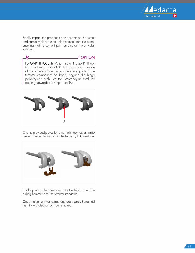
OPTIONFor GMK HINGE only: When implanting GMK Hinge, the polyethylene bush is initially loose to allow fixation of the extension stem screw. Before impacting the femoral component on bone, engage the hinge polyethylene bush into the intercondylar notch by rotating upwards the hinge post (A).
A
Clip the provided protection onto the hinge mechanism to prevent cement intrusion into the femoral/link interface.
Finally position the assembly onto the femur using the sliding hammer and the femoral impactor.
Once the cement has curred and adequately hardened the hinge protection can be removed.
32
GMK REVISION SYSTEM Surgical Technique Hip Knee Spine Navigation
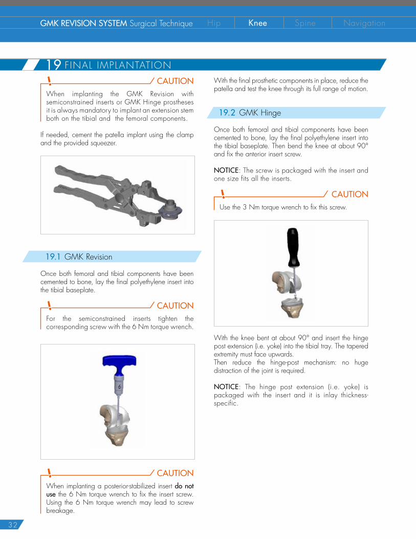
CAUTIONWhen implanting the GMK Revision with semiconstrained inserts or GMK Hinge prostheses it is always mandatory to implant an extension stem both on the tibial and the femoral components.
If needed, cement the patella implant using the clamp and the provided squeezer.
19.1 GMK Revision
Once both femoral and tibial components have been cemented to bone, lay the final polyethylene insert into the tibial baseplate.
CAUTIONFor the semiconstrained inserts tighten the corresponding screw with the 6 Nm torque wrench.
CAUTIONWhen implanting a posterior-stabilized insert do not use the 6 Nm torque wrench to fix the insert screw. Using the 6 Nm torque wrench may lead to screw breakage.
With the final prosthetic components in place, reduce the patella and test the knee through its full range of motion.
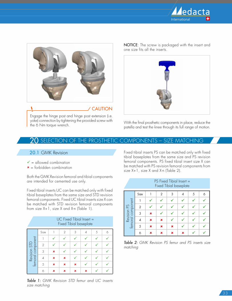
19.2 GMK Hinge
Once both femoral and tibial components have been cemented to bone, lay the final polyethylene insert into the tibial baseplate. Then bend the knee at about 90° and fix the anterior insert screw.
NOTICE: The screw is packaged with the insert and one size fits all the inserts.
CAUTIONUse the 3 Nm torque wrench to fix this screw.
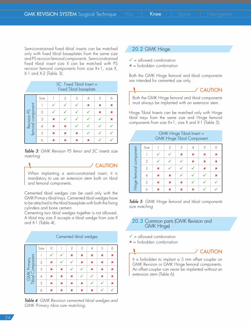
With the knee bent at about 90° and insert the hinge post extension (i.e. yoke) into the tibial tray. The tapered extremity must face upwards.Then reduce the hinge-post mechanism: no huge distraction of the joint is required.
NOTICE: The hinge post extension (i.e. yoke) is packaged with the insert and it is inlay thickness-specific.
19 F INAL IMPLANTATION
33
CAUTIONEngage the hinge post and hinge post extension (i.e. yoke) connection by tightening the provided screw with the 6 Nm torque wrench.
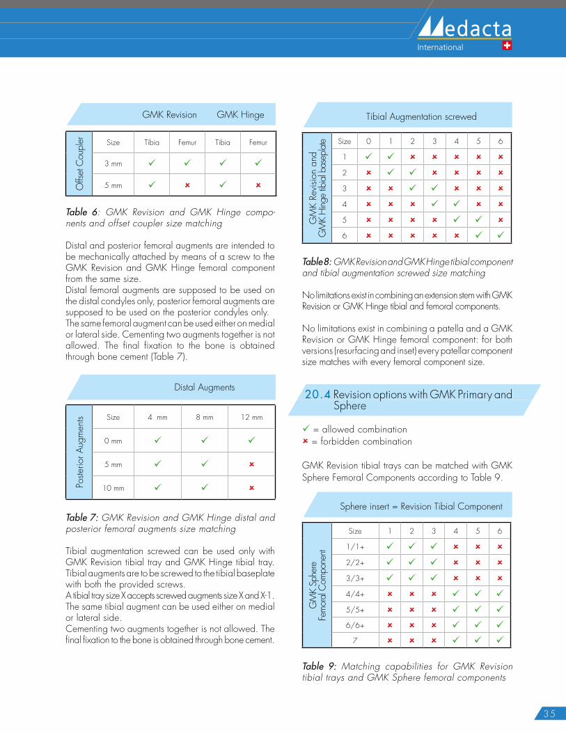
20.1 GMK Revision
9 = allowed combination 8 = forbidden combination
Both the GMK Revision femoral and tibial components are intended for cemented use only.
Fixed tibial inserts UC can be matched only with fixed tibial baseplates from the same size and STD revision femoral components. Fixed UC tibial inserts size X can be matched with STD revision femoral components from size X+1, size X and X-n (Table 1).
UC Fixed Tibial Insert = Fixed Tibial baseplate
Revis
ion
STD
fem
oral
com
pone
nt
Size 1 2 3 4 5 6
1 9 9 9 9 9 9
2 9 9 9 9 9 9
3 8 9 9 9 9 9
4 8 8 9 9 9 9
5 8 8 8 9 9 9
6 8 8 8 8 9 9
Table 1: GMK Revision STD femur and UC inserts size matching
NOTICE: The screw is packaged with the insert and one size fits all the inserts.
With the final prosthetic components in place, reduce the patella and test the knee through its full range of motion.
Fixed tibial inserts PS can be matched only with fixed tibial baseplates from the same size and PS revision femoral components. PS fixed tibial insert size X can be matched with PS revision femoral components from size X+1, size X and X-n (Table 2).
Fixed PS tibial inserts / Fixed cemented tibial tray
PS c
emen
ted
fem
oral
com
pone
nts
Size 1 2 3 4 5 6
1 9 9 9 9 9 9
2 9 9 9 9 9 9
3 8 9 9 9 9 9
4 8 8 9 9 9 9
5 8 8 8 9 9 9
6 8 8 8 8 9 9
PS Fixed Tibial Insert = Fixed Tibial baseplate
Revis
ion
PSfe
mor
al c
ompo
nent
Size 1 2 3 4 5 6
1 9 9 9 9 9 9
2 9 9 9 9 9 9
3 8 9 9 9 9 9
4 8 8 9 9 9 9
5 8 8 8 9 9 9
6 8 8 8 8 9 9
Table 2: GMK Revision PS femur and PS inserts size matching
20 SELECTION OF THE PROSTHETIC COMPONENTS – SIZE MATCHING
34
GMK REVISION SYSTEM Surgical Technique Hip Knee Spine Navigation
Semiconstrained fixed tibial inserts can be matched only with fixed tibial baseplates from the same size and PS revision femoral components. Semiconstrained fixed tibial insert size X can be matched with PS revision femoral components from size X+1, size X, X-1 and X-2 (Table 3).
SC Fixed Tibial Insert = Fixed Tibial baseplate
Revis
ion
PSfe
mor
al c
ompo
nent
Size 1 2 3 4 5 6
1 9 9 9 8 8 8
2 9 9 9 9 8 8
3 8 9 9 9 9 8
4 8 8 9 9 9 9
5 8 8 8 9 9 9
6 8 8 8 8 9 9
Table 3: GMK Revision PS femur and SC inserts size matching
CAUTIONWhen implanting a semi-constrained insert, it is mandatory to use an extension stem both on tibial and femoral components.
Cemented tibial wedges can be used only with the GMK Primary tibial trays. Cemented tibial wedges have to be attached to the tibial baseplate with both the fixing cylinders and bone cement.Cementing two tibial wedges together is not allowed. A tibial tray size X accepts a tibial wedge from size X and X-1 (Table 4).
Cemented tibial wedges
GM
K Pr
imar
yTi
bial
Com
pone
nt
Size 0 1 2 3 4 5 6
1 9 9 8 8 8 8 8
2 8 9 9 8 8 8 8
3 8 8 9 9 8 8 8
4 8 8 8 9 9 8 8
5 8 8 8 8 9 9 8
6 8 8 8 8 8 9 9
Table 4: GMK Revision cemented tibial wedges and GMK Primary tibia size matching.
20.2 GMK Hinge
9 = allowed combination 8 = forbidden combination
Both the GMK Hinge femoral and tibial components are intended for cemented use only.
CAUTIONBoth the GMK Hinge femoral and tibial components must always be implanted with an extension stem.
Hinge Tibial Inserts can be matched only with Hinge tibial trays from the same size and Hinge femoral components from size X+1, size X and X-1 (Table 5).
GMK Hinge Tibial Insert = GMK Hinge Tibial Component
Hin
ge fe
mor
al c
ompo
nent Size 1 2 3 4 5 6
1 9 9 8 8 8 8
2 9 9 9 8 8 8
3 8 9 9 9 8 8
4 8 8 9 9 9 8
5 8 8 8 9 9 9
6 8 8 8 8 9 9
Table 5: GMK Hinge femoral and tibial components size matching
20.3 Common parts (GMK Revision and GMK Hinge)
9 = allowed combination 8 = forbidden combination
CAUTIONIt is forbidden to implant a 5 mm offset coupler on GMK Revision or GMK Hinge femoral components. An offset coupler can never be implanted without an extension stem (Table 6).
35
GMK Revision GMK Hinge
Offs
et C
oupl
er Size Tibia Femur Tibia Femur
3 mm 9 9 9 9
5 mm 9 8 9 8
Table 6: GMK Revision and GMK Hinge compo-nents and offset coupler size matching
Distal and posterior femoral augments are intended to be mechanically attached by means of a screw to the GMK Revision and GMK Hinge femoral component from the same size.Distal femoral augments are supposed to be used on the distal condyles only, posterior femoral augments are supposed to be used on the posterior condyles only. The same femoral augment can be used either on medial or lateral side. Cementing two augments together is not allowed. The final fixation to the bone is obtained through bone cement (Table 7).
Distal Augments
Poste
rior A
ugm
ents Size 4 mm 8 mm 12 mm
0 mm 9 9 9
5 mm 9 9 8
10 mm 9 9 8
Table 7: GMK Revision and GMK Hinge distal and posterior femoral augments size matching
Tibial augmentation screwed can be used only with GMK Revision tibial tray and GMK Hinge tibial tray. Tibial augments are to be screwed to the tibial baseplate with both the provided screws. A tibial tray size X accepts screwed augments size X and X-1.The same tibial augment can be used either on medial or lateral side. Cementing two augments together is not allowed. The final fixation to the bone is obtained through bone cement.
Tibial Augmentation screwed
GM
K Re
visio
n an
d G
MK
Hing
e tib
ial b
asep
late Size 0 1 2 3 4 5 6
1 9 9 8 8 8 8 8
2 8 9 9 8 8 8 8
3 8 8 9 9 8 8 8
4 8 8 8 9 9 8 8
5 8 8 8 8 9 9 8
6 8 8 8 8 8 9 9
Table 8: GMK Revision and GMK Hinge tibial component and tibial augmentation screwed size matching
No limitations exist in combining an extension stem with GMK Revision or GMK Hinge tibial and femoral components.
No limitations exist in combining a patella and a GMK Revision or GMK Hinge femoral component: for both versions (resurfacing and inset) every patellar component size matches with every femoral component size.
20.4 Revision options with GMK Primary and Sphere
9 = allowed combination 8 = forbidden combination
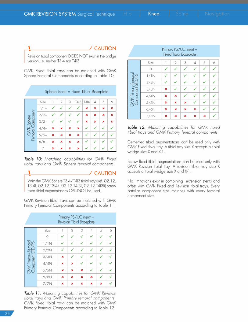
GMK Revision tibial trays can be matched with GMK Sphere Femoral Components according to Table 9.
Sphere insert = Revision Tibial Component
GM
K Sp
here
Fe
mor
al C
ompo
nent
Size 1 2 3 4 5 6
1/1+ 9 9 9 8 8 8
2/2+ 9 9 9 8 8 8
3/3+ 9 9 9 8 8 8
4/4+ 8 8 8 9 9 9
5/5+ 8 8 8 9 9 9
6/6+ 8 8 8 9 9 9
7 8 8 8 9 9 9
Table 9: Matching capabilities for GMK Revision tibial trays and GMK Sphere femoral components
36
GMK REVISION SYSTEM Surgical Technique Hip Knee Spine Navigation
CAUTIONRevision tibial component DOES NOT exist in the bridge version i.e. neither T3I4 nor T4I3
GMK Fixed tibial trays can be matched with GMK Sphere Femoral Components according to Table 10.
Sphere insert = Fixed Tibial Baseplate
GM
K Sp
here
Fe
mor
al C
ompo
nent
Size 1 2 3 T4I3 T3I4 4 5 6
1/1+ 9 9 9 9 8 8 8 8
2/2+ 9 9 9 9 8 8 8 8
3/3+ 9 9 9 9 8 8 8 8
4/4+ 8 8 8 8 9 9 9 9
5/5+ 8 8 8 8 9 9 9 9
6/6+ 8 8 8 8 9 9 9 9
7 8 8 8 8 9 9 9 9
Table 10: Matching capabilities for GMK Fixed tibial trays and GMK Sphere femoral components
CAUTIONWith the GMK Sphere T3I4/T4I3 tibial trays (ref. 02.12.T3i4L, 02.12.T3i4R, 02.12.T4i3L, 02.12.T4i3R) screw fixed tibial augmentations CANNOT be used.
GMK Revision tibial trays can be matched with GMK Primary Femoral Components according to Table 11.
Primary PS/UC insert = Revision Tibial Baseplate
GM
K Pri
mar
y Fe
mor
al
Com
pone
nt ST
D/PS
Size 1 2 3 4 5 6
0 9 9 9 9 9 9
1/1N 9 9 9 9 9 9
2/2N 9 9 9 9 9 9
3/3N 8 9 9 9 9 9
4/4N 8 8 9 9 9 9
5/5N 8 8 8 9 9 9
6/6N 8 8 8 8 9 9
7/7N 8 8 8 8 8 9
Table 11: Matching capabilities for GMK Revision tibial trays and GMK Primary femoral componentsGMK Fixed tibial trays can be matched with GMK Primary Femoral Components according to Table 12
Primary PS/UC insert = Fixed Tibial Baseplate
GM
K Pri
mar
y Fe
mor
al
Com
pone
nt ST
D/PS
Size 1 2 3 4 5 6
0 9 9 9 9 9 9
1/1N 9 9 9 9 9 9
2/2N 9 9 9 9 9 9
3/3N 8 9 9 9 9 9
4/4N 8 8 9 9 9 9
5/5N 8 8 8 9 9 9
6/6N 8 8 8 8 9 9
7/7N 8 8 8 8 8 9
Table 12: Matching capabilities for GMK Fixed tibial trays and GMK Primary femoral components
Cemented tibial augmentations can be used only with GMK Fixed tibial tray. A tibial tray size X accepts a tibial wedge size X and X-1.
Screw fixed tibial augmentations can be used only with GMK Revision tibial tray. A revision tibial tray size X accepts a tibial wedge size X and X-1.
No limitations exist in combining extension stems and offset with GMK Fixed and Revision tibial trays. Every patellar component size matches with every femoral component size.
37
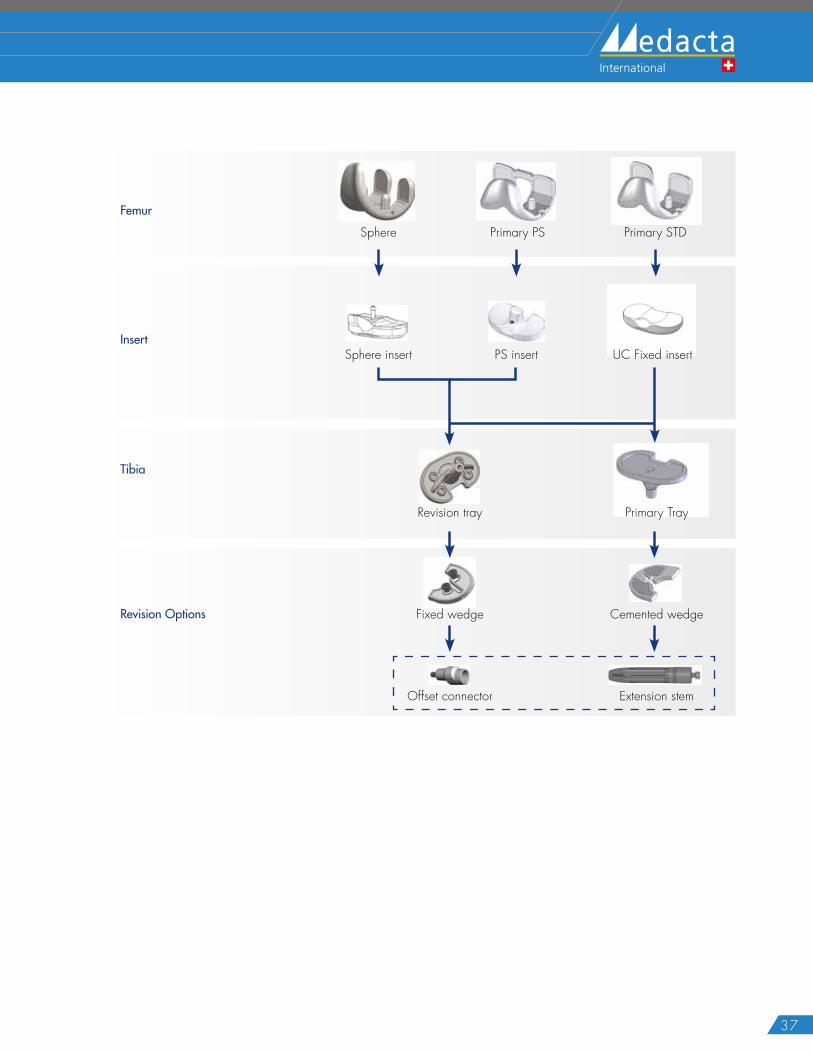
Insert
Femur
Tibia
Revision Options
Sphere Primary PS Primary STD
UC Fixed insert
Primary Tray
Sphere insert PS insert
Revision tray
Fixed wedge Cemented wedge
Offset connector Extension stem
38
GMK REVISION SYSTEM Surgical Technique Hip Knee Spine Navigation
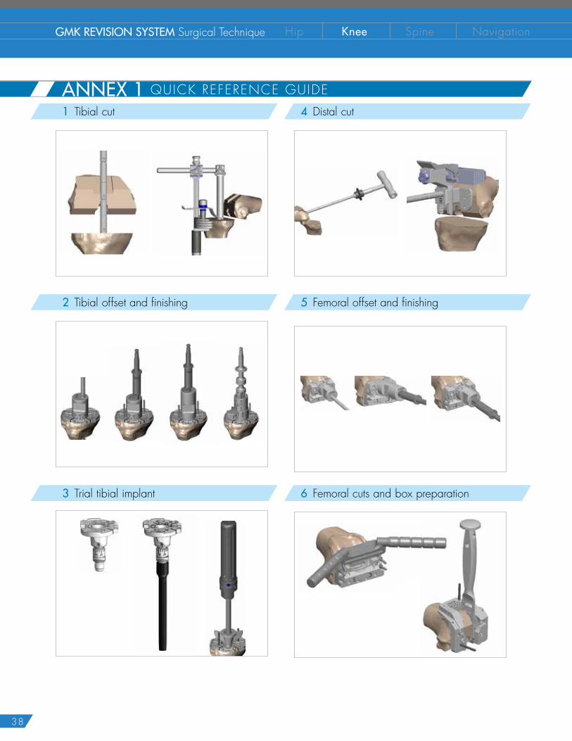
1 Tibial cut
2 Tibial offset and finishing
3 Trial tibial implant
4 Distal cut
5 Femoral offset and finishing
6 Femoral cuts and box preparation
ANNEX 1 QUICK REFERENCE GUIDE
39
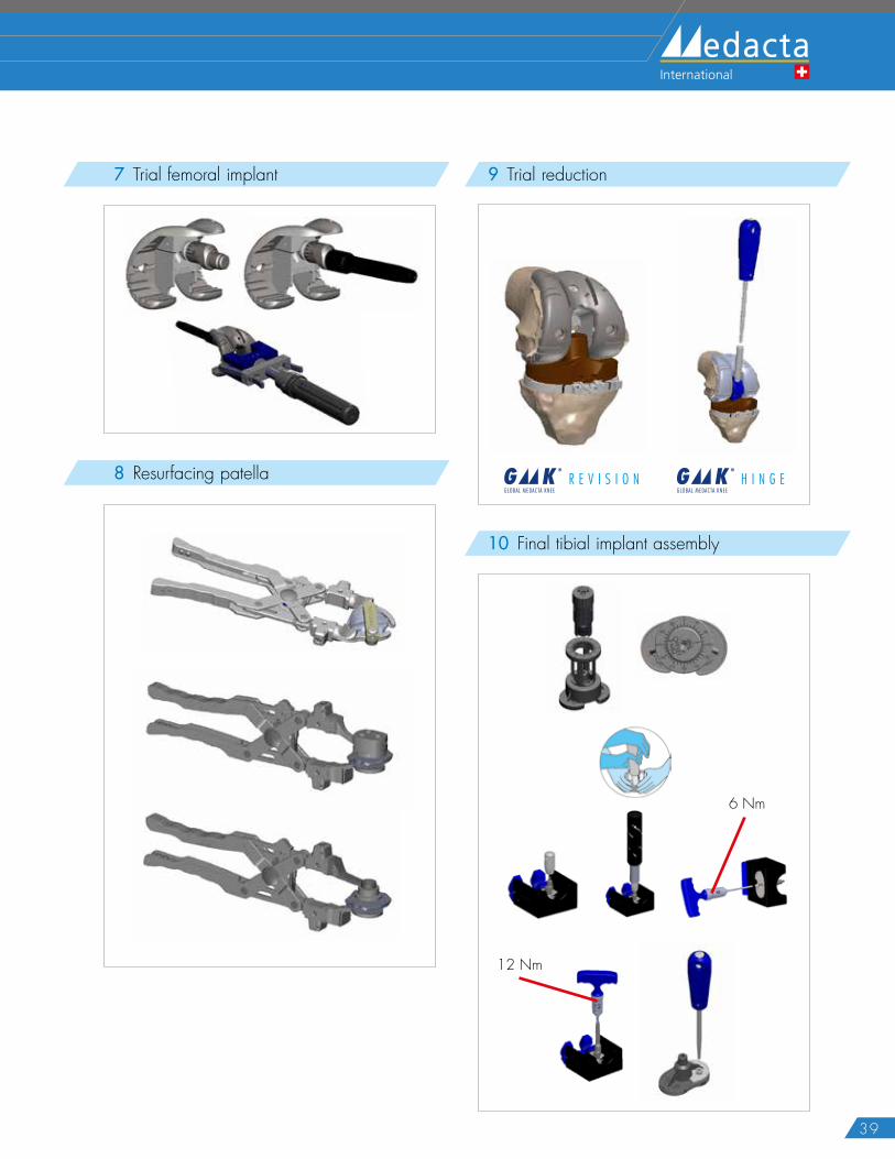
ANNEX 1 QUICK REFERENCE GUIDE 7 Trial femoral implant
8 Resurfacing patella
9 Trial reduction
G K ®
H I N G EGLOBAL MEDACTA KNEE
G K ®
R E V I S I O NGLOBAL MEDACTA KNEE
10 Final tibial implant assembly
12 Nm
6 Nm
40
GMK REVISION SYSTEM Surgical Technique Hip Knee Spine Navigation
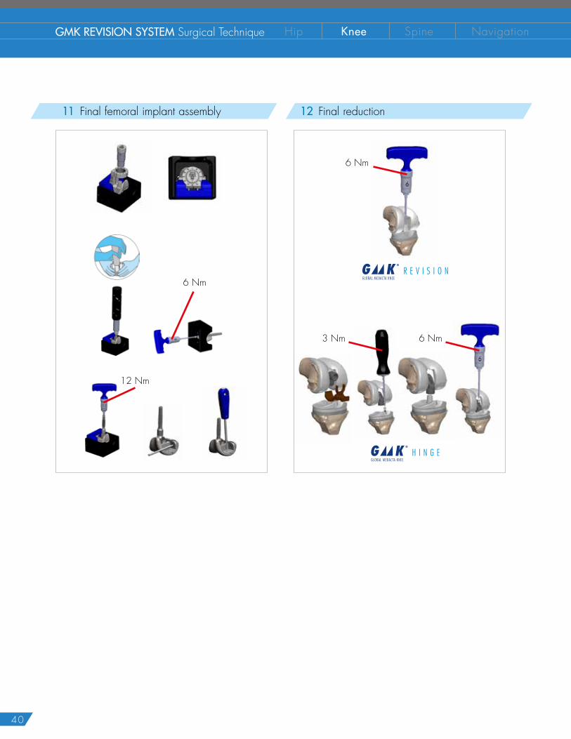
11 Final femoral implant assembly
12 Nm
6 Nm
12 Final reduction
6 Nm
6 Nm3 Nm
G K ®
H I N G EGLOBAL MEDACTA KNEE
G K ®
R E V I S I O NGLOBAL MEDACTA KNEE
41
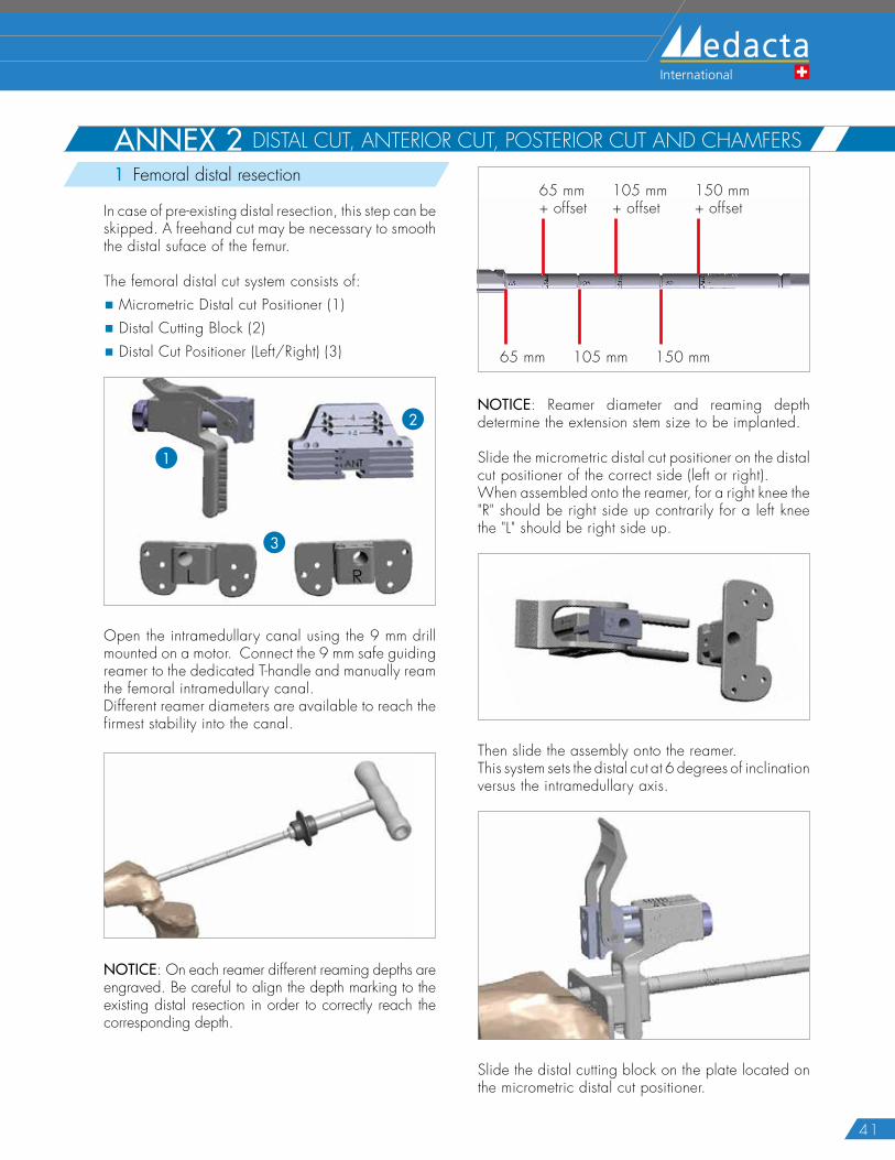
ANNEX 2 DISTAL CUT, ANTERIOR CUT, POSTERIOR CUT AND CHAMFERS1 Femoral distal resection
In case of pre-existing distal resection, this step can be skipped. A freehand cut may be necessary to smooth the distal suface of the femur.
The femoral distal cut system consists of:
� Micrometric Distal cut Positioner (1)
� Distal Cutting Block (2)
� Distal Cut Positioner (Left/Right) (3)
3
2
1
Open the intramedullary canal using the 9 mm drill mounted on a motor. Connect the 9 mm safe guiding reamer to the dedicated T-handle and manually ream the femoral intramedullary canal.Different reamer diameters are available to reach the firmest stability into the canal.
NOTICE: On each reamer different reaming depths are engraved. Be careful to align the depth marking to the existing distal resection in order to correctly reach the corresponding depth.
65 mm+ offset
65 mm+
105 mm+ offset
105 mm+
150 mm+ offset
150 mm+
NOTICE: Reamer diameter and reaming depth determine the extension stem size to be implanted.
Slide the micrometric distal cut positioner on the distal cut positioner of the correct side (left or right).When assembled onto the reamer, for a right knee the "R" should be right side up contrarily for a left knee the "L" should be right side up.
Then slide the assembly onto the reamer. This system sets the distal cut at 6 degrees of inclination versus the intramedullary axis.
Slide the distal cutting block on the plate located on the micrometric distal cut positioner.
42
GMK REVISION SYSTEM Surgical Technique Hip Knee Spine Navigation
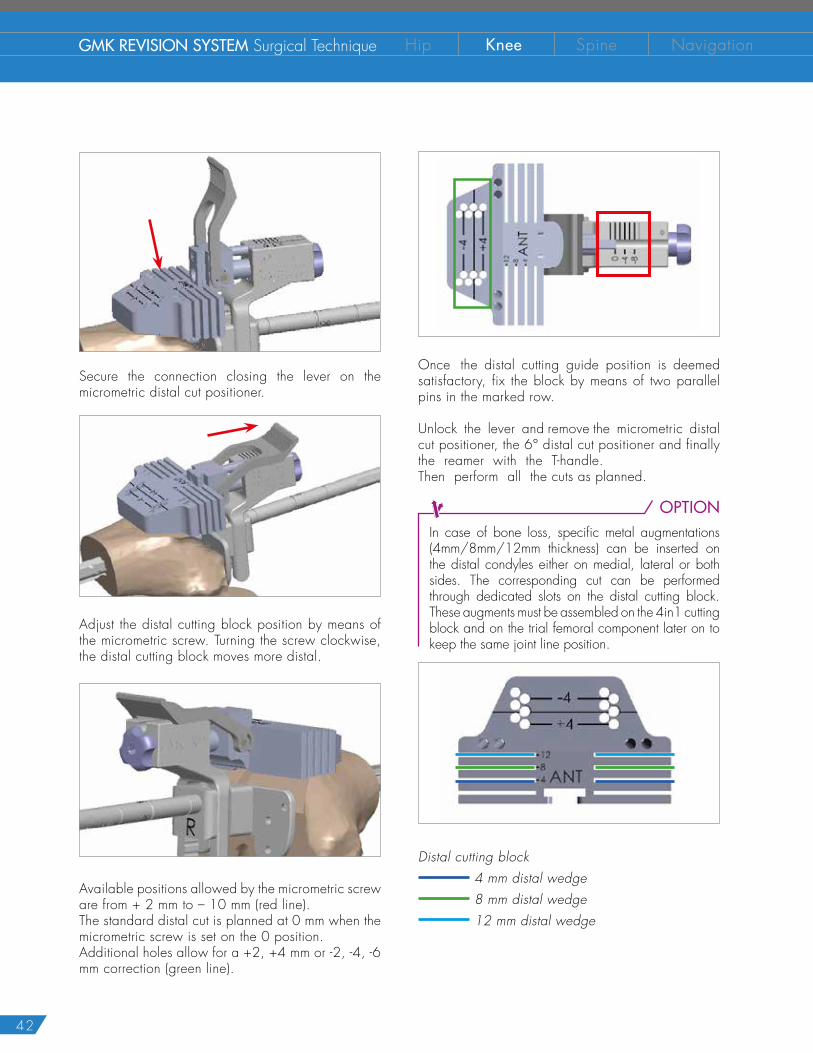
Secure the connection closing the lever on the micrometric distal cut positioner.
Adjust the distal cutting block position by means of the micrometric screw. Turning the screw clockwise, the distal cutting block moves more distal.
Available positions allowed by the micrometric screw are from + 2 mm to – 10 mm (red line).The standard distal cut is planned at 0 mm when the micrometric screw is set on the 0 position.Additional holes allow for a +2, +4 mm or -2, -4, -6 mm correction (green line).
Once the distal cutting guide position is deemed satisfactory, fix the block by means of two parallel pins in the marked row.
Unlock the lever and remove the micrometric distal cut positioner, the 6° distal cut positioner and finally the reamer with the T-handle. Then perform all the cuts as planned.
OPTIONIn case of bone loss, specific metal augmentations (4mm/8mm/12mm thickness) can be inserted on the distal condyles either on medial, lateral or both sides. The corresponding cut can be performed through dedicated slots on the distal cutting block.These augments must be assembled on the 4in1 cutting block and on the trial femoral component later on to keep the same joint line position.
Distal cutting block 4 mm distal wedge 8 mm distal wedge 12 mm distal wedge
43
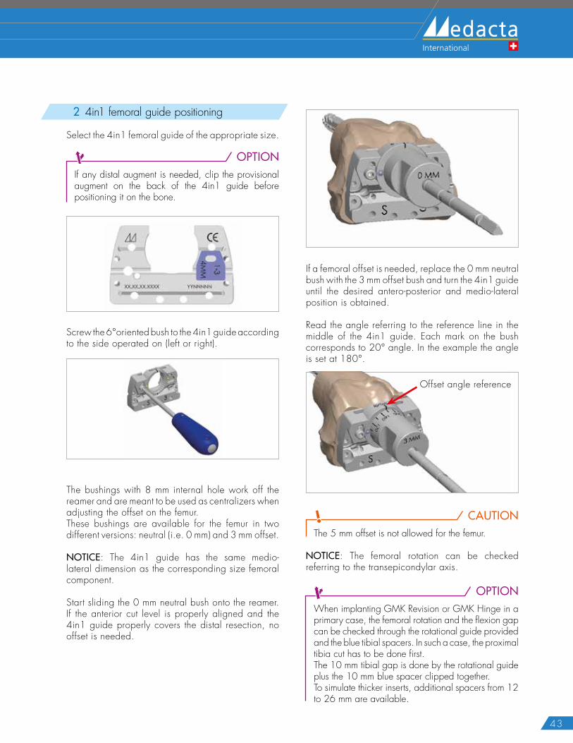
2 4in1 femoral guide positioning
Select the 4in1 femoral guide of the appropriate size.
OPTIONIf any distal augment is needed, clip the provisional augment on the back of the 4in1 guide before positioning it on the bone.
Screw the 6°oriented bush to the 4in1 guide according to the side operated on (left or right).
The bushings with 8 mm internal hole work off the reamer and are meant to be used as centralizers when adjusting the offset on the femur.These bushings are available for the femur in two different versions: neutral (i.e. 0 mm) and 3 mm offset.
NOTICE: The 4in1 guide has the same medio-lateral dimension as the corresponding size femoral component.
Start sliding the 0 mm neutral bush onto the reamer. If the anterior cut level is properly aligned and the 4in1 guide properly covers the distal resection, no offset is needed.
If a femoral offset is needed, replace the 0 mm neutral bush with the 3 mm offset bush and turn the 4in1 guide until the desired antero-posterior and medio-lateral position is obtained.
Read the angle referring to the reference line in the middle of the 4in1 guide. Each mark on the bush corresponds to 20° angle. In the example the angle is set at 180°.
Offset angle reference
CAUTIONThe 5 mm offset is not allowed for the femur.
NOTICE: The femoral rotation can be checked referring to the transepicondylar axis.
OPTIONWhen implanting GMK Revision or GMK Hinge in a primary case, the femoral rotation and the flexion gap can be checked through the rotational guide provided and the blue tibial spacers. In such a case, the proximal tibia cut has to be done first. The 10 mm tibial gap is done by the rotational guide plus the 10 mm blue spacer clipped together. To simulate thicker inserts, additional spacers from 12 to 26 mm are available.
44
GMK REVISION SYSTEM Surgical Technique Hip Knee Spine Navigation
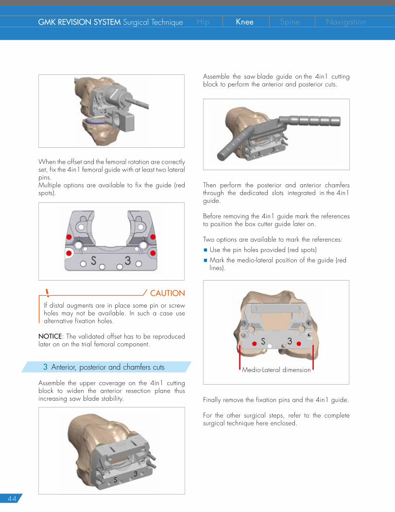
When the offset and the femoral rotation are correctly set, fix the 4in1 femoral guide with at least two lateral pins.Multiple options are available to fix the guide (red spots).
CAUTIONIf distal augments are in place some pin or screw holes may not be available. In such a case use alternative fixation holes.
NOTICE: The validated offset has to be reproduced later on on the trial femoral component.
3 Anterior, posterior and chamfers cuts
Assemble the upper coverage on the 4in1 cutting block to widen the anterior resection plane thus increasing saw blade stability.
Assemble the saw blade guide on the 4in1 cutting block to perform the anterior and posterior cuts.
Then perform the posterior and anterior chamfers through the dedicated slots integrated in the 4in1 guide.
Before removing the 4in1 guide mark the references to position the box cutter guide later on.
Two options are available to mark the references:
� Use the pin holes provided (red spots)
� Mark the medio-lateral position of the guide (red lines).
Medio-Lateral dimension
Finally remove the fixation pins and the 4in1 guide.
For the other surgical steps, refer to the complete surgical technique here enclosed.
45
ANNEX 3 CROSSOVER TECHNIQUECAUTION
This technique can be used to switch from a primary to a more constrained implant after the bone resections being performed. When implanting GMK Revision and GMK Hinge the use of a stem is mandatory both for femur and tibia. When using the crossover technique it is suggested to use a short cemented stem without the offset coupler both for femur and tibia.
1 Tibia finishing
OPTIONClip the provisional tibial augment onto the bottom of the trial baseplate before positioning it on the femur. To simulate a 10 mm augment clip two 5 mm provisional augments together.
Position the trial baseplate on the tibial cut optimizing the coverage of the resection and fix it with two pins.
Connect the reamer guide to the baseplate then ream with the conical reamer to create room for the tibial keel.
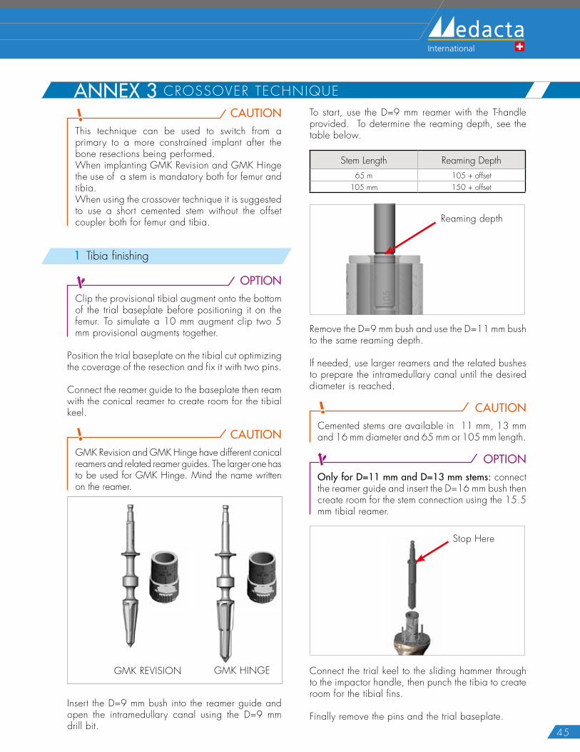
CAUTIONGMK Revision and GMK Hinge have different conical reamers and related reamer guides. The larger one has to be used for GMK Hinge. Mind the name written on the reamer.
GMK REVISION GMK HINGE
Insert the D=9 mm bush into the reamer guide and open the intramedullary canal using the D=9 mm drill bit.
To start, use the D=9 mm reamer with the T-handle provided. To determine the reaming depth, see the table below.
Stem Length Reaming Depth65 m 105 + offset
105 mm 150 + offset
Reaming depth
Remove the D=9 mm bush and use the D=11 mm bush to the same reaming depth.
If needed, use larger reamers and the related bushes to prepare the intramedullary canal until the desired diameter is reached.
CAUTIONCemented stems are available in 11 mm, 13 mm and 16 mm diameter and 65 mm or 105 mm length.
OPTIONOnly for D=11 mm and D=13 mm stems: connect the reamer guide and insert the D=16 mm bush then create room for the stem connection using the 15.5 mm tibial reamer.
Stop Here
Connect the trial keel to the sliding hammer through to the impactor handle, then punch the tibia to create room for the tibial fins.
Finally remove the pins and the trial baseplate.
46
GMK REVISION SYSTEM Surgical Technique Hip Knee Spine Navigation
OPTIONOnly for screwed augments: On the side where no augments are planned, use the drill bit and drilling template provided to create room in the tibia to accommodate the wedge holes protruding from the bottom of the baseplate.
This step may be skipped if the bone is not too hard.
2 Femur finishing
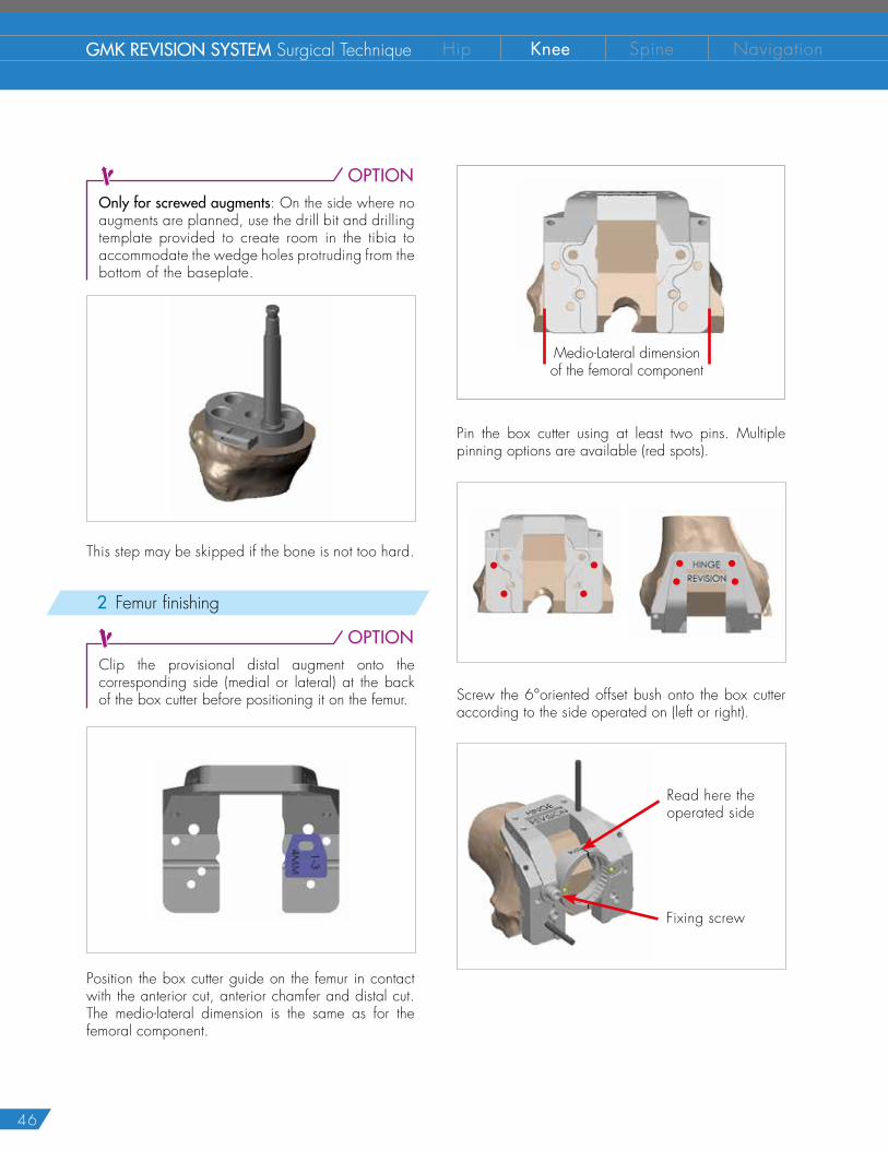
OPTIONClip the provisional distal augment onto the corresponding side (medial or lateral) at the back of the box cutter before positioning it on the femur.
Position the box cutter guide on the femur in contact with the anterior cut, anterior chamfer and distal cut. The medio-lateral dimension is the same as for the femoral component.
Medio-Lateral dimensionof the femoral component
Pin the box cutter using at least two pins. Multiple pinning options are available (red spots).
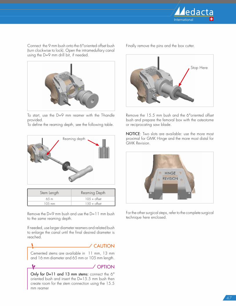
Screw the 6°oriented offset bush onto the box cutter according to the side operated on (left or right).
Read here the operated side
Fixing screw
47
Connect the 9 mm bush onto the 6°oriented offset bush (turn clockwise to lock). Open the intramedullary canal using the D=9 mm drill bit, if needed.
To start, use the D=9 mm reamer with the T-handle provided.To define the reaming depth, see the following table.
Reaming depth
Stem Length Reaming Depth65 m 105 + offset
105 mm 150 + offset
Remove the D=9 mm bush and use the D=11 mm bush to the same reaming depth.
If needed, use larger diameter reamers and related bush to enlarge the canal until the final desired diameter is reached.
CAUTIONCemented stems are available in 11 mm, 13 mm and 16 mm diameter and 65 mm or 105 mm length.
OPTIONOnly for D=11 and 13 mm stems: connect the 6° oriented bush and insert the D=15.5 mm bush then create room for the stem connection using the 15.5 mm reamer
Finally remove the pins and the box cutter.
Stop Here
Remove the 15.5 mm bush and the 6°oriented offset bush and prepare the femoral box with the osteotome or reciprocating saw blade.
NOTICE: Two slots are available: use the more most proximal for GMK Hinge and the more most distal for GMK Revision.
For the other surgical steps, refer to the complete surgical technique here enclosed.
48
GMK REVISION SYSTEM Surgical Technique Hip Knee Spine Navigation
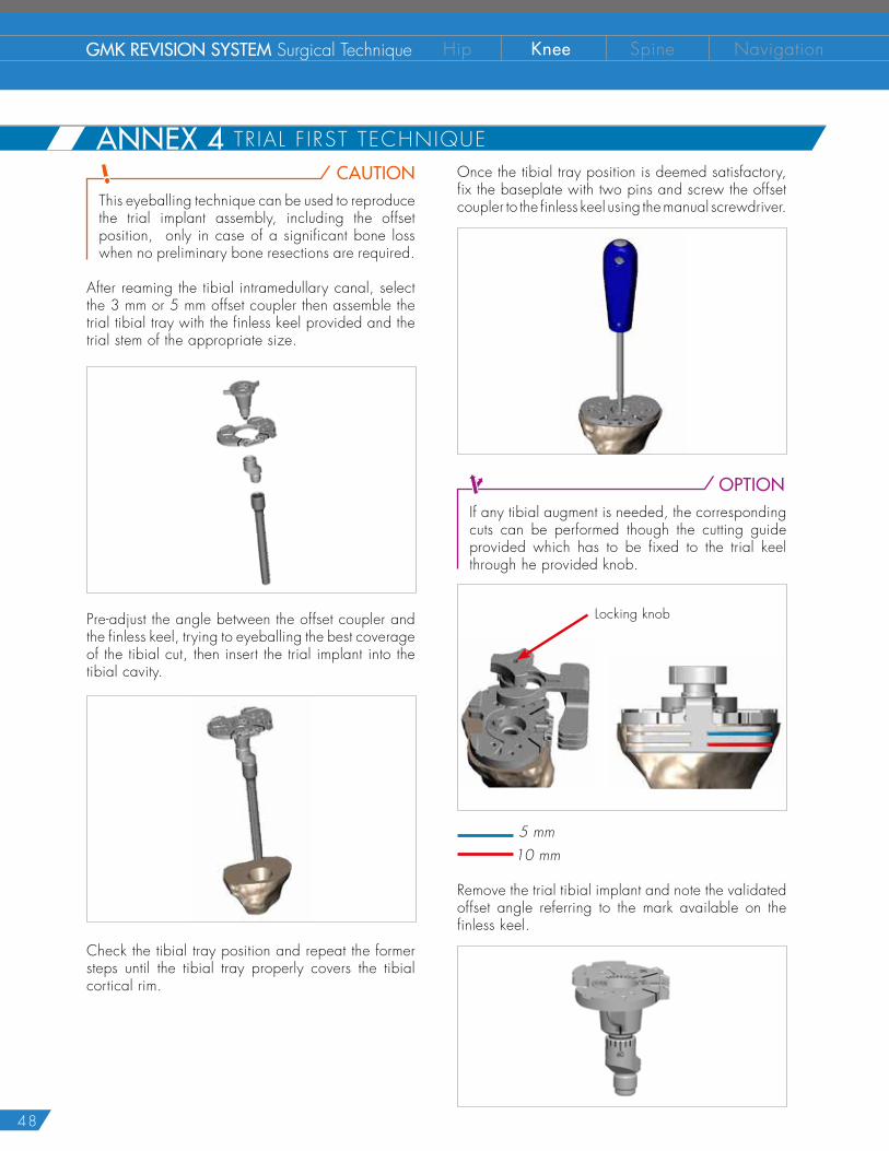
CAUTIONThis eyeballing technique can be used to reproduce the trial implant assembly, including the offset position, only in case of a significant bone loss when no preliminary bone resections are required.
After reaming the tibial intramedullary canal, select the 3 mm or 5 mm offset coupler then assemble the trial tibial tray with the finless keel provided and the trial stem of the appropriate size.
Pre-adjust the angle between the offset coupler and the finless keel, trying to eyeballing the best coverage of the tibial cut, then insert the trial implant into the tibial cavity.
Check the tibial tray position and repeat the former steps until the tibial tray properly covers the tibial cortical rim.
Once the tibial tray position is deemed satisfactory, fix the baseplate with two pins and screw the offset coupler to the finless keel using the manual screwdriver.
OPTIONIf any tibial augment is needed, the corresponding cuts can be performed though the cutting guide provided which has to be fixed to the trial keel through he provided knob.
Locking knob
5 mm 10 mm
Remove the trial tibial implant and note the validated offset angle referring to the mark available on the finless keel.
ANNEX 4 TRIAL F IRST TECHNIQUE
49
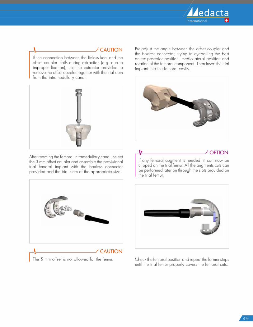
CAUTIONIf the connection between the finless keel and the offset coupler fails during extraction (e.g. due to improper fixation), use the extractor provided to remove the offset coupler together with the trial stem from the intramedullary canal.
After reaming the femoral intramedullary canal, select the 3 mm offset coupler and assemble the provisional trial femoral implant with the boxless connector provided and the trial stem of the appropriate size.
CAUTIONThe 5 mm offset is not allowed for the femur.
Pre-adjust the angle between the offset coupler and the boxless connector, trying to eyeballing the best antero-posterior position, medio-lateral position and rotation of the femoral component. Then insert the trial implant into the femoral cavity.
OPTIONIf any femoral augment is needed, it can now be clipped on the trial femur. All the augments cuts can be performed later on through the slots provided on the trial femur.
Check the femoral position and repeat the former steps until the trial femur properly covers the femoral cuts.
ANNEX 4 TRIAL F IRST TECHNIQUE
50
GMK REVISION SYSTEM Surgical Technique Hip Knee Spine Navigation
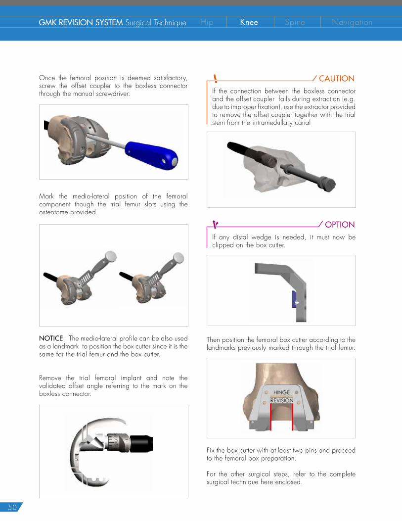
Once the femoral position is deemed satisfactory, screw the offset coupler to the boxless connector through the manual screwdriver.
Mark the medio-lateral position of the femoral component though the trial femur slots using the osteotome provided.
NOTICE: The medio-lateral profile can be also used as a landmark to position the box cutter since it is the same for the trial femur and the box cutter.
Remove the trial femoral implant and note the validated offset angle referring to the mark on the boxless connector.
CAUTIONIf the connection between the boxless connector and the offset coupler fails during extraction (e.g. due to improper fixation), use the extractor provided to remove the offset coupler together with the trial stem from the intramedullary canal
OPTIONIf any distal wedge is needed, it must now be clipped on the box cutter.
Then position the femoral box cutter according to the landmarks previously marked through the trial femur.
Fix the box cutter with at least two pins and proceed to the femoral box preparation.
For the other surgical steps, refer to the complete surgical technique here enclosed.
51
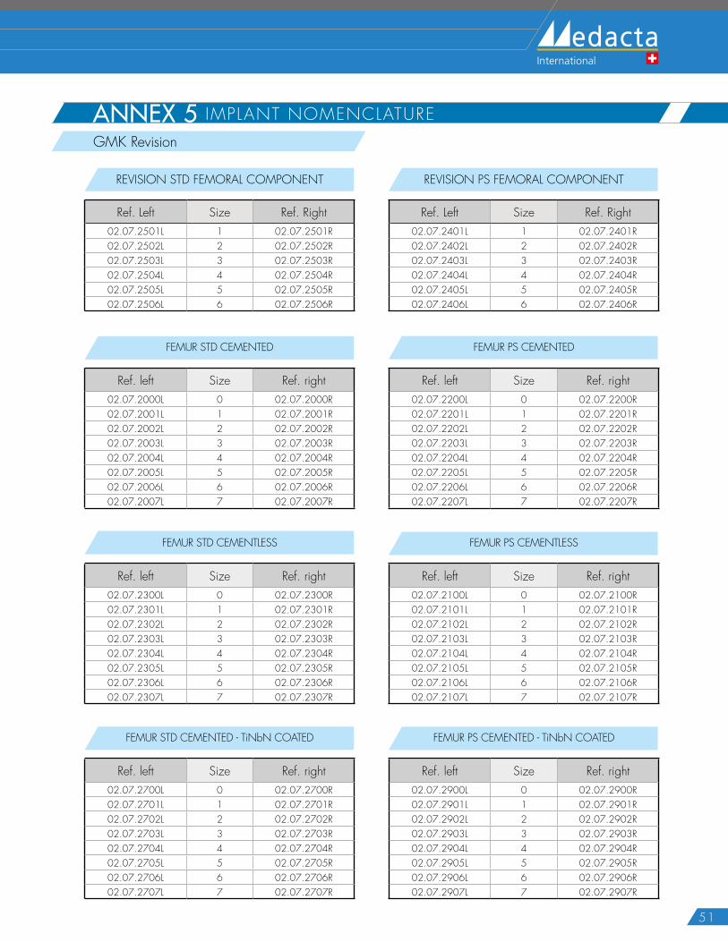
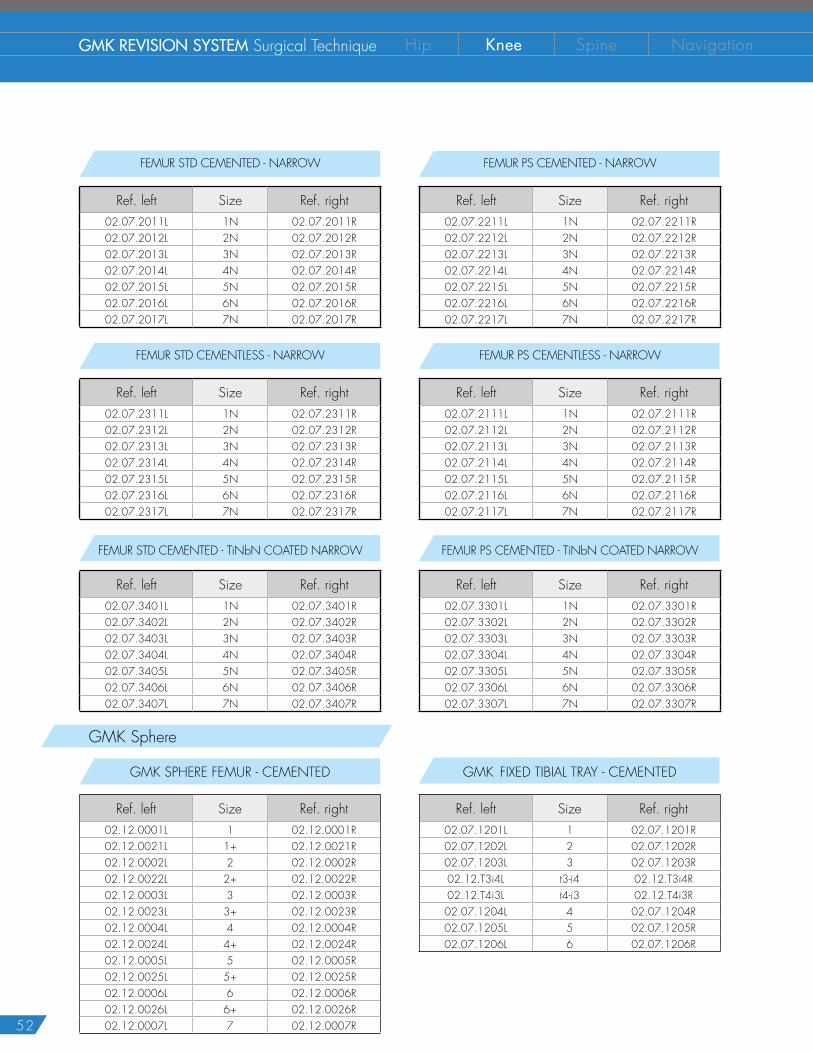
ANNEX 5 IMPLANT NOMENCLATUREGMK Revision
REVISION STD FEMORAL COMPONENT
Ref. Left Size Ref. Right02.07.2501L 1 02.07.2501R02.07.2502L 2 02.07.2502R02.07.2503L 3 02.07.2503R02.07.2504L 4 02.07.2504R02.07.2505L 5 02.07.2505R02.07.2506L 6 02.07.2506R
REVISION PS FEMORAL COMPONENT
Ref. Left Size Ref. Right02.07.2401L 1 02.07.2401R02.07.2402L 2 02.07.2402R02.07.2403L 3 02.07.2403R02.07.2404L 4 02.07.2404R02.07.2405L 5 02.07.2405R02.07.2406L 6 02.07.2406R
FEMUR PS CEMENTED - TiNbN COATED
Ref. left Size Ref. right02.07.2900L 0 02.07.2900R02.07.2901L 1 02.07.2901R02.07.2902L 2 02.07.2902R02.07.2903L 3 02.07.2903R02.07.2904L 4 02.07.2904R02.07.2905L 5 02.07.2905R02.07.2906L 6 02.07.2906R02.07.2907L 7 02.07.2907R
FEMUR STD CEMENTED - TiNbN COATED
Ref. left Size Ref. right02.07.2700L 0 02.07.2700R02.07.2701L 1 02.07.2701R02.07.2702L 2 02.07.2702R02.07.2703L 3 02.07.2703R02.07.2704L 4 02.07.2704R02.07.2705L 5 02.07.2705R02.07.2706L 6 02.07.2706R02.07.2707L 7 02.07.2707R
FEMUR PS CEMENTLESS
Ref. left Size Ref. right02.07.2100L 0 02.07.2100R02.07.2101L 1 02.07.2101R02.07.2102L 2 02.07.2102R02.07.2103L 3 02.07.2103R02.07.2104L 4 02.07.2104R02.07.2105L 5 02.07.2105R02.07.2106L 6 02.07.2106R02.07.2107L 7 02.07.2107R
FEMUR STD CEMENTLESS
Ref. left Size Ref. right02.07.2300L 0 02.07.2300R02.07.2301L 1 02.07.2301R02.07.2302L 2 02.07.2302R02.07.2303L 3 02.07.2303R02.07.2304L 4 02.07.2304R02.07.2305L 5 02.07.2305R02.07.2306L 6 02.07.2306R02.07.2307L 7 02.07.2307R
FEMUR PS CEMENTED
Ref. left Size Ref. right02.07.2200L 0 02.07.2200R02.07.2201L 1 02.07.2201R02.07.2202L 2 02.07.2202R02.07.2203L 3 02.07.2203R02.07.2204L 4 02.07.2204R02.07.2205L 5 02.07.2205R02.07.2206L 6 02.07.2206R02.07.2207L 7 02.07.2207R
FEMUR STD CEMENTED
Ref. left Size Ref. right02.07.2000L 0 02.07.2000R02.07.2001L 1 02.07.2001R02.07.2002L 2 02.07.2002R02.07.2003L 3 02.07.2003R02.07.2004L 4 02.07.2004R02.07.2005L 5 02.07.2005R02.07.2006L 6 02.07.2006R02.07.2007L 7 02.07.2007R
52
GMK REVISION SYSTEM Surgical Technique Hip Knee Spine Navigation
GMK Sphere
FEMUR PS CEMENTED - TiNbN COATED NARROW
Ref. left Size Ref. right02.07.3301L 1N 02.07.3301R02.07.3302L 2N 02.07.3302R02.07.3303L 3N 02.07.3303R02.07.3304L 4N 02.07.3304R02.07.3305L 5N 02.07.3305R02.07.3306L 6N 02.07.3306R02.07.3307L 7N 02.07.3307R
FEMUR STD CEMENTED - TiNbN COATED NARROW
Ref. left Size Ref. right02.07.3401L 1N 02.07.3401R02.07.3402L 2N 02.07.3402R02.07.3403L 3N 02.07.3403R02.07.3404L 4N 02.07.3404R02.07.3405L 5N 02.07.3405R02.07.3406L 6N 02.07.3406R02.07.3407L 7N 02.07.3407R
FEMUR PS CEMENTED - NARROW
Ref. left Size Ref. right02.07.2211L 1N 02.07.2211R02.07.2212L 2N 02.07.2212R02.07.2213L 3N 02.07.2213R02.07.2214L 4N 02.07.2214R02.07.2215L 5N 02.07.2215R02.07.2216L 6N 02.07.2216R02.07.2217L 7N 02.07.2217R
FEMUR STD CEMENTED - NARROW
Ref. left Size Ref. right02.07.2011L 1N 02.07.2011R02.07.2012L 2N 02.07.2012R02.07.2013L 3N 02.07.2013R02.07.2014L 4N 02.07.2014R02.07.2015L 5N 02.07.2015R02.07.2016L 6N 02.07.2016R02.07.2017L 7N 02.07.2017R
FEMUR PS CEMENTLESS - NARROW
Ref. left Size Ref. right02.07.2111L 1N 02.07.2111R02.07.2112L 2N 02.07.2112R02.07.2113L 3N 02.07.2113R02.07.2114L 4N 02.07.2114R02.07.2115L 5N 02.07.2115R02.07.2116L 6N 02.07.2116R02.07.2117L 7N 02.07.2117R
FEMUR STD CEMENTLESS - NARROW
Ref. left Size Ref. right02.07.2311L 1N 02.07.2311R02.07.2312L 2N 02.07.2312R02.07.2313L 3N 02.07.2313R02.07.2314L 4N 02.07.2314R02.07.2315L 5N 02.07.2315R02.07.2316L 6N 02.07.2316R02.07.2317L 7N 02.07.2317R
GMK SPHERE FEMUR - CEMENTED
Ref. left Size Ref. right02.12.0001L 1 02.12.0001R02.12.0021L 1+ 02.12.0021R02.12.0002L 2 02.12.0002R02.12.0022L 2+ 02.12.0022R02.12.0003L 3 02.12.0003R02.12.0023L 3+ 02.12.0023R02.12.0004L 4 02.12.0004R02.12.0024L 4+ 02.12.0024R02.12.0005L 5 02.12.0005R02.12.0025L 5+ 02.12.0025R02.12.0006L 6 02.12.0006R02.12.0026L 6+ 02.12.0026R02.12.0007L 7 02.12.0007R
GMK FIXED TIBIAL TRAY - CEMENTED
Ref. left Size Ref. right02.07.1201L 1 02.07.1201R02.07.1202L 2 02.07.1202R02.07.1203L 3 02.07.1203R02.12.T3i4L t3-i4 02.12.T3i4R02.12.T4i3L t4-i3 02.12.T4i3R02.07.1204L 4 02.07.1204R02.07.1205L 5 02.07.1205R02.07.1206L 6 02.07.1206R
53
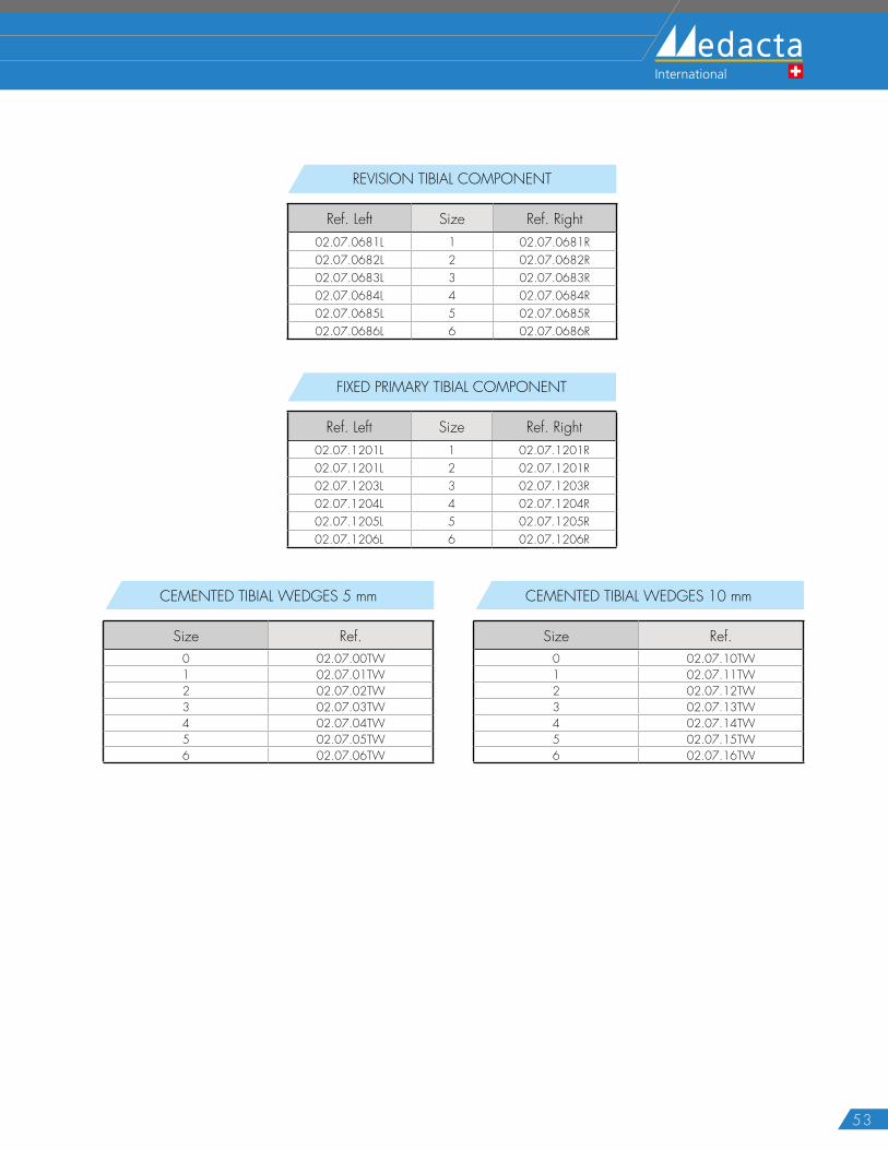
REVISION TIBIAL COMPONENT
Ref. Left Size Ref. Right02.07.0681L 1 02.07.0681R02.07.0682L 2 02.07.0682R02.07.0683L 3 02.07.0683R02.07.0684L 4 02.07.0684R02.07.0685L 5 02.07.0685R02.07.0686L 6 02.07.0686R
FIXED PRIMARY TIBIAL COMPONENT
Ref. Left Size Ref. Right02.07.1201L 1 02.07.1201R02.07.1201L 2 02.07.1201R02.07.1203L 3 02.07.1203R02.07.1204L 4 02.07.1204R02.07.1205L 5 02.07.1205R02.07.1206L 6 02.07.1206R
CEMENTED TIBIAL WEDGES 5 mm
Size Ref.0 02.07.00TW1 02.07.01TW2 02.07.02TW3 02.07.03TW4 02.07.04TW5 02.07.05TW6 02.07.06TW
CEMENTED TIBIAL WEDGES 10 mm
Size Ref.0 02.07.10TW1 02.07.11TW2 02.07.12TW3 02.07.13TW4 02.07.14TW5 02.07.15TW6 02.07.16TW
54
GMK REVISION SYSTEM Surgical Technique Hip Knee Spine Navigation
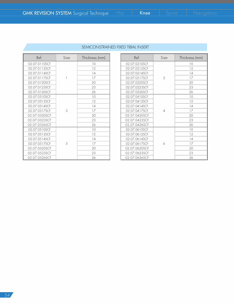
SEMICONSTRAINED FIXED TIBIAL INSERT
Ref. Size Thickness (mm) Ref. Size Thickness (mm)02.07.0110SCF
1
10 02.07.0210SCF
2
1002.07.0112SCF 12 02.07.0212SCF 1202.07.0114SCF 14 02.07.0214SCF 1402.07.0117SCF 17 02.07.0217SCF 1702.07.0120SCF 20 02.07.0220SCF 2002.07.0123SCF 23 02.07.0223SCF 2302.07.0126SCF 26 02.07.0226SCF 2602.07.0310SCF
3
10 02.07.0410SCF
4
1002.07.0312SCF 12 02.07.0412SCF 1202.07.0314SCF 14 02.07.0414SCF 1402.07.0317SCF 17 02.07.0417SCF 1702.07.0320SCF 20 02.07.0420SCF 2002.07.0323SCF 23 02.07.0423SCF 2302.07.0326SCF 26 02.07.0426SCF 2602.07.0510SCF
5
10 02.07.0610SCF
6
1002.07.0512SCF 12 02.07.0612SCF 1202.07.0514SCF 14 02.07.0614SCF 1402.07.0517SCF 17 02.07.0617SCF 1702.07.0520SCF 20 02.07.0620SCF 2002.07.0523SCF 23 02.07.0623SCF 2302.07.0526SCF 26 02.07.0626SCF 26
55
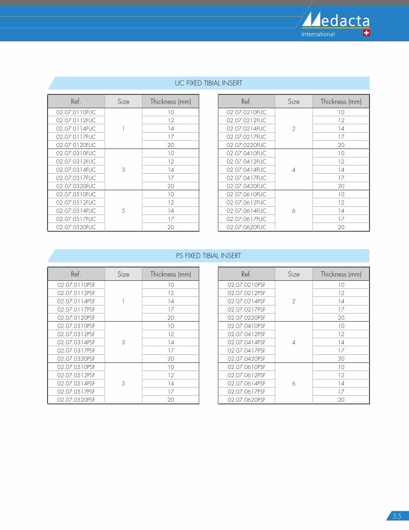
UC FIXED TIBIAL INSERT
Ref. Size Thickness (mm) Ref. Size Thickness (mm)02.07.0110FUC
1
10 02.07.0210FUC
2
1002.07.0112FUC 12 02.07.0212FUC 1202.07.0114FUC 14 02.07.0214FUC 1402.07.0117FUC 17 02.07.0217FUC 1702.07.0120FUC 20 02.07.0220FUC 2002.07.0310FUC
3
10 02.07.0410FUC
4
1002.07.0312FUC 12 02.07.0412FUC 1202.07.0314FUC 14 02.07.0414FUC 1402.07.0317FUC 17 02.07.0417FUC 1702.07.0320FUC 20 02.07.0420FUC 2002.07.0510FUC
5
10 02.07.0610FUC
6
1002.07.0512FUC 12 02.07.0612FUC 1202.07.0514FUC 14 02.07.0614FUC 1402.07.0517FUC 17 02.07.0617FUC 1702.07.0520FUC 20 02.07.0620FUC 20
PS FIXED TIBIAL INSERT
Ref. Size Thickness (mm) Ref. Size Thickness (mm)02.07.0110PSF
1
10 02.07.0210PSF
2
1002.07.0112PSF 12 02.07.0212PSF 1202.07.0114PSF 14 02.07.0214PSF 1402.07.0117PSF 17 02.07.0217PSF 1702.07.0120PSF 20 02.07.0220PSF 2002.07.0310PSF
3
10 02.07.0410PSF
4
1002.07.0312PSF 12 02.07.0412PSF 1202.07.0314PSF 14 02.07.0414PSF 1402.07.0317PSF 17 02.07.0417PSF 1702.07.0320PSF 20 02.07.0420PSF 2002.07.0510PSF
5
10 02.07.0610PSF
6
1002.07.0512PSF 12 02.07.0612PSF 1202.07.0514PSF 14 02.07.0614PSF 1402.07.0517PSF 17 02.07.0617PSF 1702.07.0520PSF 20 02.07.0620PSF 20
56
GMK REVISION SYSTEM Surgical Technique Hip Knee Spine Navigation
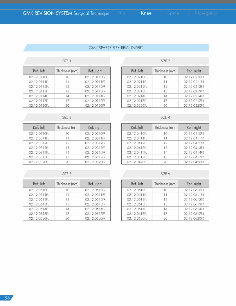
GMK SPHERE FLEX TIBIAL INSERT
SIZE 2
Ref. left Thickness (mm) Ref. right02.12.0210FL 10 02.12.0210FR02.12.0211FL 11 02.12.0211FR02.12.0212FL 12 02.12.0212FR02.12.0213FL 13 02.12.0213FR02.12.0214FL 14 02.12.0214FR02.12.0217FL 17 02.12.0217FR02.12.0220FL 20 02.12.0220FR
SIZE 1
Ref. left Thickness (mm) Ref. right02.12.0110FL 10 02.12.0110FR02.12.0111FL 11 02.12.0111FR02.12.0112FL 12 02.12.0112FR02.12.0113FL 13 02.12.0113FR02.12.0114FL 14 02.12.0114FR02.12.0117FL 17 02.12.0117FR02.12.0120FL 20 02.12.0120FR
SIZE 4
Ref. left Thickness (mm) Ref. right02.12.0410FL 10 02.12.0410FR02.12.0411FL 11 02.12.0411FR02.12.0412FL 12 02.12.0412FR02.12.0413FL 13 02.12.0413FR02.12.0414FL 14 02.12.0414FR02.12.0417FL 17 02.12.0417FR02.12.0420FL 20 02.12.0420FR
SIZE 3
Ref. left Thickness (mm) Ref. right02.12.0310FL 10 02.12.0310FR02.12.0311FL 11 02.12.0311FR02.12.0312FL 12 02.12.0312FR02.12.0313FL 13 02.12.0313FR02.12.0314FL 14 02.12.0314FR02.12.0317FL 17 02.12.0317FR02.12.0320FL 20 02.12.0320FR
SIZE 6
Ref. left Thickness (mm) Ref. right02.12.0610FL 10 02.12.0610FR02.12.0611FL 11 02.12.0611FR02.12.0612FL 12 02.12.0612FR02.12.0613FL 13 02.12.0613FR02.12.0614FL 14 02.12.0614FR02.12.0617FL 17 02.12.0617FR02.12.0620FL 20 02.12.0620FR
SIZE 5
Ref. left Thickness (mm) Ref. right02.12.0510FL 10 02.12.0510FR02.12.0511FL 11 02.12.0511FR02.12.0512FL 12 02.12.0512FR02.12.0513FL 13 02.12.0513FR02.12.0514FL 14 02.12.0514FR02.12.0517FL 17 02.12.0517FR02.12.0520FL 20 02.12.0520FR
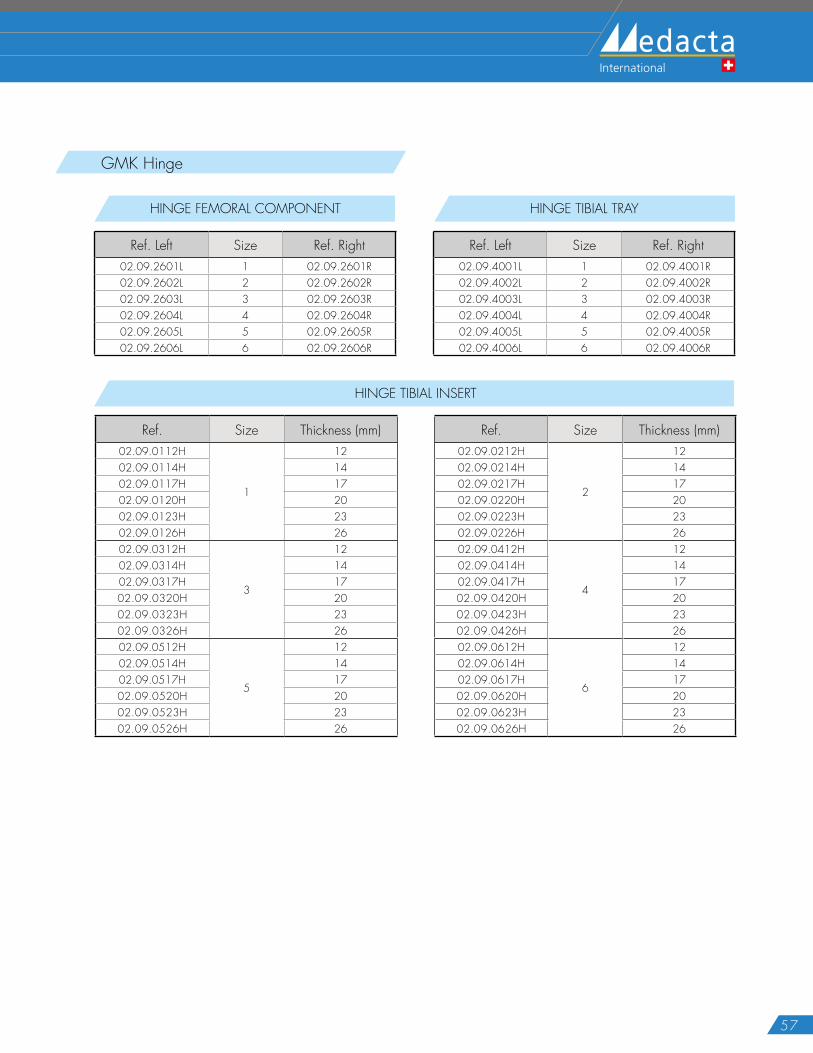
57
GMK Hinge
HINGE FEMORAL COMPONENT
Ref. Left Size Ref. Right02.09.2601L 1 02.09.2601R02.09.2602L 2 02.09.2602R02.09.2603L 3 02.09.2603R02.09.2604L 4 02.09.2604R02.09.2605L 5 02.09.2605R02.09.2606L 6 02.09.2606R
HINGE TIBIAL TRAY
Ref. Left Size Ref. Right02.09.4001L 1 02.09.4001R02.09.4002L 2 02.09.4002R02.09.4003L 3 02.09.4003R02.09.4004L 4 02.09.4004R02.09.4005L 5 02.09.4005R02.09.4006L 6 02.09.4006R
HINGE TIBIAL INSERT
Ref. Size Thickness (mm) Ref. Size Thickness (mm)02.09.0112H
1
12 02.09.0212H
2
1202.09.0114H 14 02.09.0214H 1402.09.0117H 17 02.09.0217H 1702.09.0120H 20 02.09.0220H 2002.09.0123H 23 02.09.0223H 2302.09.0126H 26 02.09.0226H 2602.09.0312H
3
12 02.09.0412H
4
1202.09.0314H 14 02.09.0414H 1402.09.0317H 17 02.09.0417H 1702.09.0320H 20 02.09.0420H 2002.09.0323H 23 02.09.0423H 2302.09.0326H 26 02.09.0426H 2602.09.0512H
5
12 02.09.0612H
6
1202.09.0514H 14 02.09.0614H 1402.09.0517H 17 02.09.0617H 1702.09.0520H 20 02.09.0620H 2002.09.0523H 23 02.09.0623H 2302.09.0526H 26 02.09.0626H 26
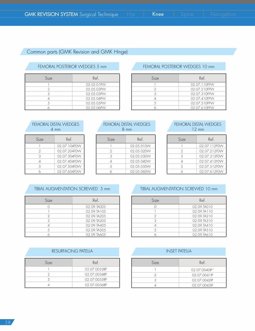
58
GMK REVISION SYSTEM Surgical Technique Hip Knee Spine Navigation
Common parts (GMK Revision and GMK Hinge)
FEMORAL POSTERIOR WEDGES 5 mm
Size Ref.1 02.05.01PW2 02.05.02PW3 02.05.03PW4 02.05.04PW5 02.05.05PW6 02.05.06PW
FEMORAL POSTERIOR WEDGES 10 mm
Size Ref.1 02.07.110FPW2 02.07.210FPW3 02.07.310FPW4 02.07.410FPW5 02.07.510FPW6 02.07.610FPW
TIBIAL AUGMENTATION SCREWED 5 mm
Size Ref.0 02.09.TA0051 02.09.TA1052 02.09.TA2053 02.09.TA3054 02.09.TA4055 02.09.TA5056 02.09.TA605
TIBIAL AUGMENTATION SCREWED 10 mm
Size Ref.0 02.09.TA0101 02.09.TA1102 02.09.TA2103 02.09.TA3104 02.09.TA4105 02.09.TA5106 02.09.TA610
FEMORAL DISTAL WEDGES 4 mm
Size Ref.1 02.07.104FDW2 02.07.204FDW3 02.07.304FDW4 02.07.404FDW5 02.07.504FDW6 02.07.604FDW
FEMORAL DISTAL WEDGES8 mm
Size Ref.1 02.05.01DW2 02.05.02DW3 02.05.03DW4 02.05.04DW5 02.05.05DW6 02.05.06DW
FEMORAL DISTAL WEDGES12 mm
Size Ref.1 02.07.112FDW2 02.07.212FDW3 02.07.312FDW4 02.07.412FDW5 02.07.512FDW6 02.07.612FDW
RESURFACING PATELLA
Size Ref.1 02.07.0033RP2 02.07.0034RP3 02.07.0035RP4 02.07.0036RP
INSET PATELLA
Size Ref.1 02.07.0040IP i
2 02.07.0041IP3 02.07.0042IP4 02.07.0043IP
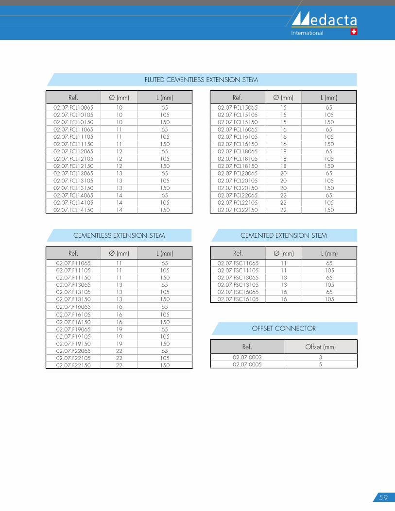
59
OFFSET CONNECTOR
Ref. Offset (mm)02.07.0003 302.07.0005 5
FLUTED CEMENTLESS EXTENSION STEM
Ref. Ø (mm) L (mm) Ref. Ø (mm) L (mm)02.07.FCL10065 10 65 02.07.FCL15065 15 6502.07.FCL10105 10 105 02.07.FCL15105 15 10502.07.FCL10150 10 150 02.07.FCL15150 15 15002.07.FCL11065 11 65 02.07.FCL16065 16 6502.07.FCL11105 11 105 02.07.FCL16105 16 10502.07.FCL11150 11 150 02.07.FCL16150 16 15002.07.FCL12065 12 65 02.07.FCL18065 18 6502.07.FCL12105 12 105 02.07.FCL18105 18 10502.07.FCL12150 12 150 02.07.FCL18150 18 15002.07.FCL13065 13 65 02.07.FCL20065 20 6502.07.FCL13105 13 105 02.07.FCL20105 20 10502.07.FCL13150 13 150 02.07.FCL20150 20 15002.07.FCL14065 14 65 02.07.FCL22065 22 6502.07.FCL14105 14 105 02.07.FCL22105 22 10502.07.FCL14150 14 150 02.07.FCL22150 22 150
CEMENTLESS EXTENSION STEM
Ref. Ø (mm) L (mm)02.07.F11065 11 6502.07.F11105 11 10502.07.F11150 11 15002.07.F13065 13 6502.07.F13105 13 10502.07.F13150 13 15002.07.F16065 16 6502.07.F16105 16 10502.07.F16150 16 15002.07.F19065 19 6502.07.F19105 19 10502.07.F19150 19 15002.07.F22065 22 6502.07.F22105 22 10502.07.F22150 22 150
CEMENTED EXTENSION STEM
Ref. Ø (mm) L (mm)02.07.FSC11065 11 6502.07.FSC11105 11 10502.07.FSC13065 13 6502.07.FSC13105 13 10502.07.FSC16065 16 6502.07.FSC16105 16 105

60
GMK REVISION SYSTEM Surgical Technique Hip Knee Spine Navigation
NOTES

61

62
GMK REVISION SYSTEM Surgical Technique Hip Knee Spine Navigation

63
The instrumentation is not sterile upon delivery. It must be cleaned before use and sterilized in an autoclave respecting the regulations of the country US, directives where applicable and following the instruction for use of the autoclave manufacturer.For detailed instructions please refer to the document “Recommendations for cleaning decontamination and sterilization of Medacta® International reusable orthopedic devices” available at www.medacta.com.
GMK® Revision, GMK® Hinge and Medacta® are registered trademarks of Medacta® International SA, Castel San Pietro, Switzerland.
N O T E F O R S T E R I L I Z A T I O N
Part numbers subject to change.

GMK Revision SystemSurgical Technique
ref: 99.27S.12USrev. 02
Last Update: March 2016
D I S T R I B U T E D B Y
Medacta International SA Strada Regina - 6874 Castel San PietroSwitzerlandPhone +41 91 696 60 60 Fax +41 91 696 60 [email protected]
Medacta USA, Inc.1556 West Carroll Avenue - ChicagoIl l inois 60607Phone +1 312 878 2381Fax +1 312 546 [email protected]