Ground Trac
4
<<Page 1 >> Copyright 6-2002 Profession al Solar Produ cts Ground T rac ™ support channel and clamping design is protected by patent #6,360,491 other patents pending. Use by permission only. PV GROUND MOUNT SYSTEM By: Professional Solar Products Ground Trac™ TOOL LIST: 1. Post hole digger 2. Wheelbarrow / shovel 3. String Line 4. Line level or builders level 5. Drill 6. 1/2” Uni-Bit 7. Tape Measure 8. Sharpie™ marking pen 9. 7/16” deep socket & ratchet 10. Phillips head driver (for drywall screws) 11. 1/2” wrench 12. 3/16” hex wrench 13. Framing square 14. Pipe cutter or reciprocating saw 15. Pipe wrenches (two required) 16. Mallet or large hammer GROUND TRAC™ INSTALLATION OVERVIEW: The Ground Trac ™ PV mounting system is a simple, easy to install, fully engineered ground mount solution for photovoltaic solar modules. This system is designed to engineer with a minimum amount of installed footings at greatly reduced labor. The system integrates with ordinary 1 -1/4” schedule #40 galvanized pipe. Ground Trac™ includes virtually everything needed to install modules with vertical posts up to 5” from grade. The installer will only need pipe, concrete and basic construction skills to complete the installation. Ground Trac™ utilizes Professional Solar Products’ patented Slide-n-Clamp™ module clamps and support channel - the industry standard for rooftop module installations. Installation of the Ground Trac™ system consists of the following: • Installation 1-1/4” schedule #40 galvanized pipe (maximum span = 10’ O.C. using the special alloy tees). • Installation of vertical pipe supports into concrete footings. • Drilling and installation of the main support channels to the specially machined “U-Bolt” assemblies. • Installation of the solar modules using the standard Roof Trac™ “Slide-n-Clamp” module mounting system.
Transcript of Ground Trac
8/8/2019 Ground Trac
http://slidepdf.com/reader/full/ground-trac 1/4
<<Page 1 >>
Copyright 6-2002 Professional Solar Products Ground Trac™ support channel and clamping design is protected by patent#6,360,491 other patents pending. Use by permission only.
PV GROUND MOUNT SYSTEMBy: Professional Solar Products
Ground Trac™ TOOL LIST:
1. Post hole digger
2. Wheelbarrow / shovel3. String Line
4. Line level or builders level
5. Drill
6. 1/2” Uni-Bit
7. Tape Measure
8. Sharpie™ marking pen
9. 7/16” deep socket & ratchet
10. Phillips head driver (for drywall screws)11. 1/2” wrench
12. 3/16” hex wrench
13. Framing square
14. Pipe cutter or reciprocating saw
15. Pipe wrenches (two required)
16. Mallet or large hammer
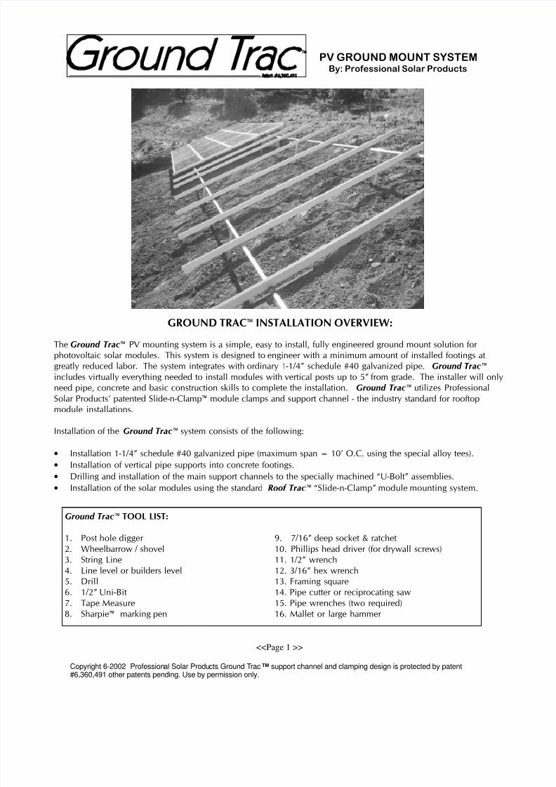
GROUND TRAC™ INSTALLATION OVERVIEW:
The Ground Trac ™ PV mounting system is a simple, easy to install, fully engineered ground mount solution for
photovoltaic solar modules. This system is designed to engineer with a minimum amount of installed footings at
greatly reduced labor. The system integrates with ordinary 1-1/4” schedule #40 galvanized pipe. Ground Trac™
includes virtually everything needed to install modules with vertical posts up to 5” from grade. The installer will only
need pipe, concrete and basic construction skills to complete the installation. Ground Trac™ utilizes Professional
Solar Products’ patented Slide-n-Clamp™ module clamps and support channel - the industry standard for rooftop
module installations.
Installation of the Ground Trac™ system consists of the following:
• Installation 1-1/4” schedule #40 galvanized pipe (maximum span = 10’ O.C. using the special alloy tees).
• Installation of vertical pipe supports into concrete footings.
• Drilling and installation of the main support channels to the specially machined “U-Bolt” assemblies.
• Installation of the solar modules using the standard Roof Trac™ “Slide-n-Clamp” module mounting system.

8/8/2019 Ground Trac
http://slidepdf.com/reader/full/ground-trac 2/4
<<Page 2 >>
Copyright 6-2002 Professional Solar Products Ground Trac™ support channel and clamping design is protected by patent#6,360,491 other patents pending. Use by permission only.
PV GROUND MOUNT SYSTEMBy: Professional Solar Products
Excavate footings as per detail or engineered plan
STEP #1
STEP #2
Illustrated (left) pipe support beams and vertical
post supports can now be assembled and rest
on the support bracing. Using two pipe
wrenches and 3/16” hex wrench, the pipe and
support legs can be assembled and are readyfor the Ground Trac™ module channel to be
installed.
STEP #3
Rear view of pipe support beam bracing and
GRADE STAKESUPPORTS
THREADED PIPECOUPLER
SIDE VIEW
SIDE VIEW
SIDE VIEW
3 5 . 0 °
Special Note: Use only schedule #40 galvanized pipe,
fence tube is not recommended
Determine the proper angle for the module array
and install grade stakes as illustrated (left), do not
exceed 5 ft. of vertical post length from grade.
Installing the supports braces will hold the pipe
at the proper fixed angle until the footings are
poured. We recommend the use of drywall
screws to hold the horizontal brace in place until
concrete sets. Install the end braces and then set
up a string line to insure alignment. Place
supports at a distance that will allow the pipebeam to be supported without sagging.
Existing Grade
Distance of base depends
upon the angle of support
channel.
Existing Grade
Existing Grade
Existing Grade

8/8/2019 Ground Trac
http://slidepdf.com/reader/full/ground-trac 3/4
<<Page 3 >>
Copyright 6-2002 Professional Solar Products Ground Trac™ support channel and clamping design is protected by patent#6,360,491 other patents pending. Use by permission only.
PV GROUND MOUNT SYSTEMBy: Professional Solar Products
STEP #5
STEP #6
End View: “U-Bolt”Attachment insertNote: The proper installationposition of the insert.
“U-BOLT” Assemblyside view
Completed assembon the support pipe
STEP #4
Drilling of the support channels: Align the support rails with the bottom side up on a flat surface. Using a framing square as
illustrated, measure from the center of the channel 41” outward and mark a line on the channel. Mark another line exactly 2”
outward from center from the first line. Now drill the “U-Bolt” holes in alignment with the marked line and the specially
extruded “V” groove on the channel. We recommend the use of a 1/2” “Uni-Bit®” bit for this. You will now have perfectly
aligned holes ready for installation on the support pipe beams.
Align the end of the channel using a string line.
Tighten all the “U-Bolt” assemblies and re-check
alignment the vertical pipe supports. You are now
ready to pour concrete into the footings. Tap the
concrete to ensure contact with the vertical pipesupport. Remove the support bracing after the
concrete has set. You are now ready to install
your modules.
CAUTION: Extruded edges of the aluminum can be sharp. It is highly recommended the installerBuff the edges after installation to prevent injury.
Existing Grade
Existing Grade
GROUD TRAC™ SUPPORTCHANNEL
2 INCHES
41 INCHES41 INCHES
CENTER
1/2" "U-BOLT HOLES

8/8/2019 Ground Trac
http://slidepdf.com/reader/full/ground-trac 4/4
<<Page 4 >>
Copyright 6-2002 Professional Solar Products Ground Trac™ support channel and clamping design is protected by patent#6,360,491 other patents pending. Use by permission only.
PV GROUND MOUNT SYSTEMBy: Professional Solar Products
MAXIMUM SPAN = 10’ USING #40 GALVANIZED PIPEPIPE OVERHANGMAXIMUM 24”
FIGURE 1
FIGURE 2
2 4 . 0
"
6 0 .
0 "
5' MAX HEIGHT
ESTIMATING AMOUNT OF PIPE AND CONCRETE:
1 To estimate the amount of galvanized pipe needed for the rack, count the total number of panelized
modules in a bank. Determine the width of the module, for example (58” x number of grouped
panels (6) = 348” x 2 = 696” / 12 = 58’) Since galvanized pipe comes in 21’ lengths, you will need
6 lengths for the upper and lower beams to avoid cutting and threading the pipe.
2 To determine the number of posts (the maximum allowable span is 10’) take the total length of one of
the beams less 4’ (2’ allowable overhang on each end) and divide this by 10 (see figure 1). This will
give you the amount of posts required to support one of the beams, doubling this will give you the
number of posts and TEE’s required.
3 Estimating the amount of pipe required for the posts can be estimated by adding 24” (footing) plus the
distance from the top of the footing -grade to the beam (figure 2). Add the total length of pipe for the
beams and the footings and divide by 21 (standard length of pipe). This will give you the amount of
pipe lengths needed required for the installation.
4 Concrete for the footings = approximately 2 cubic feet per post.
Recommended Safety Installation Procedures:
1 Installer must insure that all sharp extrusion
edges should be buffed and smooth to avoid
injuries from sharp extrusion edges.
2 All pipe ends should be capped using a
1-1/4” PVC slip caps.
3 When ground mount racking is installed in
common areas, it must be properly lit to avoid
injury from people walking into it.
4 If installed on steep slopes or unstable soil,
footings should be sufficiently sized or
engineered for these conditions.
5 Observe all electrical safety procedures andensure proper grounding as established by both
the module and inverter manufacturers.
6 Insure all support TEE set screws are properly
tightened and always use schedule #40
galvanized pipe (fence post is not
recommended).