GREENHILL PARK STAGES 16-26 DESIGN GUIDELINES
55
JULY 2021 / Rev A GREENHILL PARK STAGES 16-26 DESIGN GUIDELINES
Transcript of GREENHILL PARK STAGES 16-26 DESIGN GUIDELINES

JU
LY 2
02
1 /
Re
v A
GREENHILL PARK STAGES 16-26DES IGN GUIDEL INES

The Design Guidelines for Greenhill Park must be read in conjunction with the relevant Hamilton City district plan provisions. This design guideline is applicable to stages 16 - 26 of Greenhill Park only. Stages are illustrated on the diagram to the left. Note that all stages are within the Ruakura Medium Density Zone except for stage 24 which is within the General Residential Zone.
16
D I A G R A M — 1Staging
CARRS ROAD
17
25A
1920
18
21
22
23
24
25B
26
WEBB DRIVE GR
EE
NH
ILL
PA
RK
DE
SIG
N G
UID
ELI
NE
S S
TAG
ES
16
-26
2

CONTENTS
I N T R O D U C T I O N
S I T E D E S I G N
D E S I G N F O R Q U A L I T Y
A R C H I T E C T U R E
L A N D S C A P E
D E S I G N R E V I E W P A N E L
4
6
8
9
2 2
5 3
GR
EE
NH
ILL
PA
RK
DE
SIG
N G
UID
ELI
NE
S S
TAG
ES
16
-26
3

The integrated planning and design of houses, roads and open spaces is fundamental to achieving high quality residential neighbourhoods. The design and placement of houses creates the character of the streets.
The relationship between houses and streets are critical in establishing the conditions and characteristics for sunlight, daylighting and privacy as well as the overall neighbourhood character. Well designed houses, streets and open spaces can create excellent liveable neighbourhoods that are highly valued and benefit all that reside there.
The guidelines have been developed to preserve and enhance the value of your property, by maintaining standards across the whole development.
This project is about creating such a place, for those that will live there.
INTRODUCTION
V I S I O N
Greenhill Park is an expanding masterplanned Hamilton suburb that showcases high quality houses, streets and public spaces providing a new way of living. A mixture of lot and house sizes and typologies provide choices and value.
Chedworth Properties Limited is developing high quality streets and public places that provide the opportunity for quality houses to be developed. Guidelines will control the quality of the residential development, along with the use of a design panel process ensuring security for those purchasing in Greenhill Park.
Greenhill Park is one of the most desirable suburbs of Hamilton — it provides a range of living opportunities and will be available to a wide proportion of the community, including a range of demographics throughout all stages of life.
P U R P O S E
The purpose of these guidelines is to control the form and the quality of residential development in Greenhill Park.
By ensuring that a consistent, high quality approach is taken to the design and construction of houses and front yard landscapes at Greenhill Park, builders and residents will have confidence that neighbouring properties will be of equal or similar quality, elevating the quality and value of the entire neighbourhood, as well as the houses within.
GR
EE
NH
ILL
PA
RK
DE
SIG
N G
UID
ELI
NE
S S
TAG
ES
16
-26
4

S T R A T E G Y
In order to ensure that Greenhill Park delivers on the vision of becoming one of Hamilton's most desirable suburbs, a strategy is required for the design and construction of the suburb, the public amenities and the houses that all contribute to the overall quality of Greenhill Park.
Chedworth Properties Ltd will do this by —
• Ensuring a mixture of house types, section sizes and lot widths, within each street and throughout Greenhill Park.
• Ensuring houses actively face the street, creating an interactive street environment and community.
• Providing excellent public spaces, streets and reserves for the community. These investments will improve the value of the whole neighbourhood and all of the properties within it.
• Creating a design guideline and a design review panel to administer the process.
• Controlling the architecture to create good quality, well designed contemporary homes for a variety of people and families, i.e. not all the same market or community sector.
• Ensuring that there is variety in the streetscape and the architectural treatment of houses.
• Controlling the front yard landscape design and implementation to create a high quality street environment.
Stef
an M
orae
l Tui
n A
rchi
tect
, Bru
ssel
Martin Luther King Park — Atelier Jacqueline Osty and Associates
TrekFit Outdoor Fitness Solutions
London Studio Architects
5

NOTE - * As Stage 24 is within the general residential zone, seperate controls are given which relate to this zone where they differ.
L O T S
The lot sizes and widths are set out in the Subdivision Scheme Plan which fits into the wider Master Plan. The Master Plan has been developed to ensure a range of section sizes and widths throughout each street and each stage. Variety will be encouraged and controlled through the Design Review Panel.
S I T E C O V E R A G E A N D P E R M E A B I L I T Y
The maximum site coverage is 50% for all lots and the minimum permeability across the site is 20%. Minimum permeability forward of the front building line is 50% to encourage grass and plants while managing stormwater run-off. * For stage 24, site coverage is maximum 40% and the minimum permeability across the site is 30%. Minimum permeability forward of the front building line is 50%.
S I TE DES IGN
B U I L D I N G S E T B A C K S
TRANSPORT CORRIDOR SETBACKArterial Roads, including Webb Drive — 5 metresCollector Roads and Local Roads, including Local Access Roads and Lanes — 3 metres
FRONT YARDWhere the minimum setback of houses to the front boundary is 3 metres, a front yard of 3 to 5 metres is encouraged to promote a staggered building line along the street while ensuring houses continuously address the street environment. Garages need to be setback a minimum of 5m from the property boundary.
SIDE YARDIt is the combination of side yards on either side of a house that creates the openness or gaps between houses. The side yards at Greenhill Park open up the space on the north and west side of the lots allowing sun into living areas and yards. Side yards with a predominately northerly or westerley aspect shall be a minimum of 2m while side yards with a predominately easterly or southerly aspect shall be a minimum of 1m. This relationship
GR
EE
NH
ILL
PA
RK
DE
SIG
N G
UID
ELI
NE
S S
TAG
ES
16
-26
6
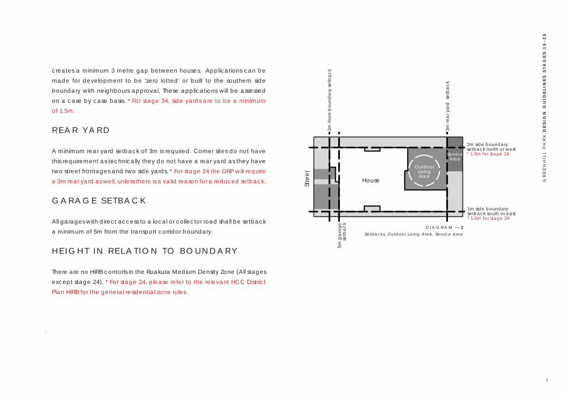
creates a minimum 3 metre gap between houses. Applications can be made for development to be 'zero lotted' or built to the southern side boundary with neighbours approval. These applications will be assessed on a case by case basis. * For stage 24, side yards are to be a minimum of 1.5m.
R E A R Y A R D
A minimum rear yard setback of 3m is required. Corner sites do not have this requirement as technically they do not have a rear yard as they have two street frontages and two side yards. * For stage 24 the DRP will require a 3m rear yard as well, unless there is a valid reason for a reduced setback.
G A R A G E S E T B A C K
All garages with direct access to a local or collector road shall be setback a minimum of 5m from the transport corridor boundary.
H E I G H T I N R E L A T I O N T O B O U N D A R Y
There are no HIRB contorls in the Ruakura Medium Density Zone (All stages except stage 24). * For stage 24, please refer to the relevant HCC District Plan HIRB for the general residential zone rules .
1m side boundary setback south or east* 1.5m for stage 24
2m side boundary setback north or west * 1.5m for stage 24
3m fr
ont b
ound
ary
setb
ack
House
OutdoorLiving Area
ServiceArea
D I A G R A M — 2Setbacks, Outdoor Living Area, Service Area
5m g
arag
e se
tbac
k
3m re
ar y
ard
set
back
Stre
et
GR
EE
NH
ILL
PA
RK
DE
SIG
N G
UID
ELI
NE
S S
TAG
ES
16
-26
7

In order to create the right conditions for the development of a high quality residential suburb, it is important to control key aspects of the neighbourhood. This is called setting the building blocks. The following section outlines the key building blocks to be controlled at Greenhill Park.
S E T T I N G T H E B U I L D I N G B L O C K S
Create a mixture of section sizes and widths that require a variety of built outcomes.Create a mixture of two storey and single storey homes to promote diversity of housing stock and formCreate street definition by controlling setback, height and specific street environments.Control key aspects of the design that impact on the community feel of the development — corners, street ends, entrances and key sites.Build the structures. Deliver excellent streetscapes and reserves that leverage community feel and participation.
DESIGN FOR QUALITY
M A T E R I A L S
Quality materials will be used in the construction of all facets of the houses, fences, walls and landscape features to ensure durability and functionality.
Some materials may lower the quality of the neighbourhood. These materials are discouraged from use —
Fibre cement board.Reflective glass.Bitumen coated soft board.Unpainted or unstained rough sawn timber.Timber or steel framed construction systems supporting monolithic cladding systems (plaster is acceptable on concrete and masonry, including brick veneer).
GR
EE
NH
ILL
PA
RK
DE
SIG
N G
UID
ELI
NE
S S
TAG
ES
16
-26
8

The following elements are required to comply with minimum standards —
L O T T Y P E S / E D G E T R E A T M E N T S A N D T H E I R S P E C I F I C R E Q U I R E M E N T SD E V E L O P M E N T B L O C K S A N D T H E I R S P E C I F I C R E Q U I R E M E N T SH O M E S T A R R A T I N GB U I L D I N G H E I G H TG A R A G E D O O R SO N S I T E P A R K I N GH O U S E O R I E N T A T I O NR O O F F O R MV A R I E T YO U T D O O R L I V I N G A R E A SR E C E S S I O N P L A N E SP R I V A C YS O L A R A C C E S S F R O M T H E N O R T HM A S S I N GE N T R A N C EW I N D O W SV E R A N D A S A N D B A L C O N I E SO U T B U I L D I N G S A N D S T R U C T U R E ST V A E R I A L S A N D M A S T SL I N T E L S
ARCHITECTURE

Small Lots
Extra Small LotsCorner lotsKey
High Profile Frontage
Comprehens ive Development Lots
D I A G R A M — 3Specific Lot Requirements
Lots Fronting Open Space
Standard Lot
Neighbourhood Cente** Subject to Seperate Design Guidance
L O T T Y P E S A N D E D G E T R E A T M E N T S
CARRS ROAD
WEBB DRIVE
Extra Small Lot With Outdoor / Service Area Relaxation (see page 12)
GR
EE
NH
ILL
PA
RK
DE
SIG
N G
UID
ELI
NE
S S
TAG
ES
16
-26
1 0

C O R N E R L O T S
The design of the lot and the house should address both streets, with windows and outdoor living areas. Corner lots should be considered carefully to ensure that the house addresses both streets and wraps around the corner. Indoor living areas should be placed and designed to interact with both sides of the corner lots.
S M A L L L O T S
Small lots are typically 300 - 339m2. A high proportion are required to be two storeys to ensure setback controls can be met and that there is still sufficient outdoor living space at ground level. Some single storey homes may be approved at the DRP's discretion depending on the quality of the design outcome.
E X T R A S M A L L L O T S
Extra small lots are typically between 200 - 300m2 and require further design consideration including zero-lotting (zero boundary setback for garage on most southern or eastern boundrary) and careful layout of the home. These lots must be two-storey homes. The following page of the design guide highlights typical typologies to demonstrate an acceptable design solution and provides further information.
C O M P R E H E N S I V E D E V E L O P M E N T L O T S
Comprehensive development lots are to be designed comprehensively.
Buildings are to be a minimum of two-storeys in height and may be up to three-storeys. It is critical that the DRP is engaged early on in the design process as design expectations are high for these lots. Further information is provided on pages 13 - 16.
S T A N D A R D L O T S
Standard lots are typically 340m2 or larger and are of a size that a single storey home can be made to work well. There is often width for a double garage while still maintaining the required maximum 50% frontage width for the garage itself.
H I G H P R O F I L E F R O N T A G E S
Frontages at the end of streets, on corners and in locations where they are highly visible are to be high quality and use premium materials. An overall higher level of architectural merit and finish will be expected for these frontages. Roof designs are to be more prominent with strong, simple forms and additional height / steeper pitch.
L O T S F R O N T I N G O P E N S P A C E
Houses that have a boundary interface with an open space will be required to activate this edge, have sufficient surveillance of the open space and be of a high design quality along this boundary.
GR
EE
NH
ILL
PA
RK
DE
SIG
N G
UID
ELI
NE
S S
TAG
ES
16
-26
1 1

File Ref: 1703_289_Area_K_L_Masterplan_Concept_Rev_P.indd
| Date: 25 September 2020 | Revision: Q |
GREENHILL PARK - LDP AREAS K, L AND U
Plan prepared for Chedworth Properties Limited by Adapt Studio LimitedS T U D I O
Appendix 16 - Typical Small Lot TypologiesDrawing Number: 1703_289q
FOR RESOURCE CONSENTFOR RESOURCE CONSENT
STRE
ETST
REET
TYPICAL SMALL LOT HOUSE TYPOLOGY, TYPICAL SMALL LOT HOUSE TYPOLOGY, typically 210m typically 210m 22 (10.5 x 20m) (10.5 x 20m)TYPICAL SITE AREA = 210m2
BUILDING COVERAGE = 85.6m2 / 40.8%PERMEABILITY FRONT YARD = 19m2 / 50.6%PERMEABILITY OVERALL = 69.0m2 / 32.9%SERVICE COURT = 10.0m2 3M DIA CIRCLEOUTDOOR LIVING AREA = 40M2 5M DIA CIRCLE
1:200 @ A3
0 6m
STRE
ETST
REET
TYPICAL SMALL LOT HOUSE TYPOLOGY, TYPICAL SMALL LOT HOUSE TYPOLOGY, typically 280m typically 280m 22 (14 x 20m) (14 x 20m)
STRE
ETST
REET
TYPICAL SMALL LOT HOUSE TYPOLOGY, TYPICAL SMALL LOT HOUSE TYPOLOGY, typically 300m typically 300m 22 (15 x 20m) (15 x 20m)
1. All house layouts and designs are indicative only and meant to give an indication of one potential design only and as a proof of concept.2. Variation in design will be achieved during design phase in both floorplan / materiality / colour selection and landscape treatment.
NO
TES
TYPICAL SITE AREA = 280m2
BUILDING COVERAGE = 115.5m2 / 41.3%PERMEABILITY FRONT YARD = 29.3m2 / 50.5%PERMEABILITY OVERALL = 94.0m2 / 33.6%SERVICE COURT = 20.0m2 3M DIA CIRCLEOUTDOOR LIVING AREA = 40M2 6M DIA CIRCLE
TYPICAL SITE AREA = 300m2
BUILDING COVERAGE = 122.9m2 / 41.0%PERMEABILITY FRONT YARD = 31.3m2 / 50.8%PERMEABILITY OVERALL = 95.7m2 / 31.9%SERVICE COURT = 20.0m2 3M DIA CIRCLEOUTDOOR LIVING AREA = 40M2 6M DIA CIRCLE
E X T R A S M A L L L O T T Y P O L O G I E S
All lots less than 300m2 require additional design consideration to be successful and must be two storey homes. Variation in materiality, colour and landscape design must be provided to ensure variation between homes. Note that comprehensive development blocks are subject to seperate controls and further information is provided on pages 13 - 16 for these blocks.
A resource consent has been obtained for delivery of homes on some of the smaller of these "extra small lots" including allowance for infringements of the outdoor living area circle diameter (5m dia instead of 6m dia), and service area size (10m2 instead of 20m2). Note that the service area still needs to fit a 3m diameter circle. The lots which have this relaxation are lot #'s 512, 513, 514, 515, 516, 517, 518, 547, 548, 549, 551, 552, 553, 554, 555,
D I A G R A M — 4Extra Small Lot Typologies
556, 557, 558, 559, 561, 562, 563, 564, 565, 578, 579, 607, 608, 624, 625, 626, 628, 629, 631, 632, 634, 635, 637, 638, 639, 643, 644, 645, 647, 648, 650, 651, 653, 654, 656, 657, 658, 673, 674, 691, 692, 708, 709, 728, 729, 730, 732, 733, 734, 738, 739, 740, 741, 742, 744, 745, 746, 747, 748 and 749. These lots are shown by a dark grey dot on the Lot Types Plan on page 10. A copy of this resource consent is attached to each sale and purchase agreement.
The below diagrams showcase indicative acceptable typologies for the most common exta small lot sizes - noting that they all show a garage which is "zero lotted" on their most southern or eastern boundary and that this is an expected and encouraged design outcome.
R E F E R R E S O U R C E C O N S E N T # 0 1 0 . 2 0 1 9 . 1 0 7 9 0 . 0 0 1
GR
EE
NH
ILL
PA
RK
DE
SIG
N G
UID
ELI
NE
S S
TAG
ES
16
-26
1 2
12
4
1215A
15B
15C
3
14A
14B13A
13B
6
7
89
10
11
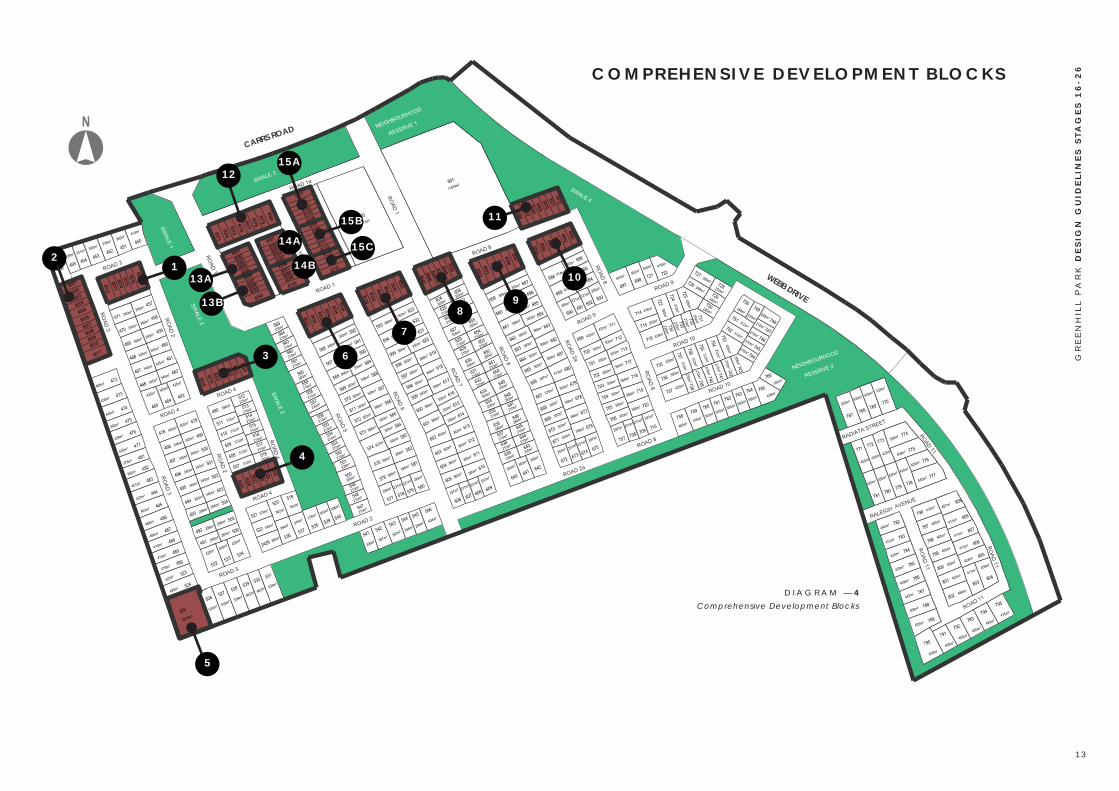
D I A G R A M — 4Comprehensive Development Blocks
C O M P R E H E N S I V E D E V E L O P M E N T B L O C K S
CARRS ROAD
WEBB DRIVE
5
GR
EE
NH
ILL
PA
RK
DE
SIG
N G
UID
ELI
NE
S S
TAG
ES
16
-26
1 3

C O M P R E H E N S I V E D E V E L O P M E N T B L O C K S
There are 19 seperate comprehensive development blocks as outlined on diagram 4 on the previous page. Each of these blocks is to consist of a series of two to three storey attached terrace or duplex homes. Apartment typologies may be considered by the DRP if the design outcome is excellent noting that you will require additional resource consents from HCC. Architectural variation is to be provided between the blocks and a gap between built form is to be included where two development blocks have a shared boundary. A series of assessment criteria outline the performance standards that the DRP will use to assess the design outcomes for these homes. Additional requirements are outlined below.
• The design of the comprehensive development blocks are to be bespoke design solutions and you must engage a reputable and competent architectural firm to undertake the design.
• You must undertake all three stages of the review process as outlined on pages 53 -55.
• Deisgn must integrate / consider the design of adjoining freestanding homes.
• Early engagement with the DRP is required to ensure that the design meets the panels expectations.
NOTE - This section only applies to the Comprehensive Development Blocks
" L o o k a n d F e e l E x a m p l e s F o r C o m p r e h e n s i v e D e v e l o p m e n t B l o c k s
GR
EE
NH
ILL
PA
RK
DE
SIG
N G
UID
ELI
NE
S S
TAG
ES
16
-26
1 4

A S S E S S M E N T C R I T E R I A
1. Buildings need to be designed to form a positive relationship with the street and parks so that:
• They provide for streetscape and park amenity, through the careful placement of entry doors, windows, porches, balconies, entry courtyards as these attributes help to create an active frontage to the street.
• They demonstrate the transition between the street or park (public realm), the building’s front yard (semi-public realm) and the building’s rear yard.
• Visitors know how to access the building.
2. Design balconies so that they face onto public roads / parks, including a clear outlook which is not of adjacent properties. It is preferable that balconies which face roads be designed as recessed elements so they do not protrude from the face of buildings.
3. Site buildings to maximise sunlight into indoor and outdoor areas:
• Maximise north, west and east facing windows.• Maximise exposure to private open space.
4. Make provision within each residential unit for:
• Collection of recyclable materials and an area for rubbish bins, ensuring they are located and designed not to be visible from the street or parks.
" L o o k a n d F e e l E x a m p l e s F o r C o m p r e h e n s i v e D e v e l o p m e n t B l o c k s
GR
EE
NH
ILL
PA
RK
DE
SIG
N G
UID
ELI
NE
S S
TAG
ES
16
-26
1 5

• Storage area for outdoor equipment e.g. bicycles, prams, sports equipment etc.
5. Use landscaping to provide visual interest, create privacy and shelter people from prevailing winds.
6. Maximise privacy between dwellings by taking extra care over the interface at the sides of adjacent buildings which are not connected by a party wall.
7. Design buildings so they provide visual interest, diversity and variation. This helps to avoid monotonous repetition of building form including: roof pitches, materials, decks, courtyards, balconies and other detailing.
8. Design buildings to address local conditions including street orientation, laneway configuration (if there is one), views and climate. Use eaves to control summer sun, provide shelter from rain and shelter courtyards from wind.
9. Avoid locating satellite dishes and clothes lines at the front of buildings. Locate these items so they are not clearly visible from the street or park.
10. Garages which are accessed from the street need to be designed and located so that:
• There is sufficient space to park a car between the site’s front boundary and the front of the garage.
• Garages are set back from the dwelling’s main façade.• They relate to the building’s design in terms of height, roof form,
materials, detailing and colours. " L o o k a n d F e e l E x a m p l e s F o r C o m p r e h e n s i v e D e v e l o p m e n t B l o c k s
GR
EE
NH
ILL
PA
RK
DE
SIG
N G
UID
ELI
NE
S S
TAG
ES
16
-26
1 6

H O M E S T A R ™ R A T I N G
All houses will be designed to achieve a minimum of a Homestar™ Rating of 6 or equivalent. The below link to the Homestar™ checklist for standalone homes is to give an idea of the design and construction aspects required to meet a rating of 6 and is for information only. The DRP will not be requiring that the official Homestar process be undertaken.https://www.nzgbc.org.nz/Attachment?Action=Download&Attachment_id=3844
B U I L D I N G H E I G H T
The maximum height of buildings is 10m.* For stage 24, please refer to the relevant HCC District Plan General Residential Zone height rule.
G A R A G E D O O R S
The design guidelines encourage garage doors to be setback at least 0.5 metres from the front of the house to reduce the dominance of garages on the streetscape. Garage doors should occupy a maximum of 50% of the width of the front elevation of the house and be a minimum of 5m from the transport corridor boundary to ensure space for a car to park without blocking the footpath.
O N S I T E C A R P A R K I N G
A minimum of three on site carparks are required for homes with four or more bedrooms with a minimum of two of these being in either a side by side or in a stacked garage. At grade carparking must be in front of a
garage door and no seperate parking pads not in front of the garage will be approved.
H O U S E O R I E N T A T I O N
Houses should be designed to positively address the street — front doors and indoor living areas should have a relationship with the street. Windows from living areas should be included in the front of each house and should face the street.
R O O F F O R M
Roof forms should be designed to emphasize the vertical dimensions and be simple in form — either gables, mono-pitched, skillion or similar simple roof forms are acceptable. No hip roofs will be accepted. A high proportion of attached homes are to have steep gabled roof forms.
The roof form over the living part of the house should be more dominant than the roof form over the garage, through increasing or stepped height. The residential roof form should be the primary roof form and should include the pedestrian entrance. The roof form over the garage should generally be secondary and less prominent.
V A R I E T Y
Variation is required through form, roof-line, massing, materials, colour and detail. No two houses should be of the same or similar design within a sequence of four houses in a street. * This is at the discretion of the Design Review Panel.
GR
EE
NH
ILL
PA
RK
DE
SIG
N G
UID
ELI
NE
S S
TAG
ES
16
-26
1 7

Space Division Architects, Auckland
Seaview House, by Jackson Clements Burrows Architects
Paua Architects, Le Quesnoy Place, Cambridge
'Look And Feel' Examples For Architecture
A staggered building line is encouraged along the street
Lots fronting lane and open space Massing articulated to emphasise the pedestrian entrance to the house
Roof forms designed to emphasise the vertical dimensions
Le Quesnoy Place, Cambridge, by Paua Architects
Architect Luc Bouliane
1 8

Proctor And Matthews Architects
Willemsen U Architects
Hobs
onvi
lle, A
uckl
and
Tech
ne A
rchi
tect
ure
+ In
terio
r Des
ign
'Look And Feel' Examples For Fences, Walls And Letterboxes
DM
OA
Arc
hite
cten
Outdoor living areas
Lots fronting open space
Low boundary fence interface with open space
Privacy fence
Anselmi Ridge
Massing articulated to emphasise the pedestrian entrance to the house
Front doors and indoor living areas with a relationship to the street Cambridge Building Services
Elwood, by Inform Designs
1 9

O U T D O O R L I V I N G A R E A S
Outdoor living areas shall be provided on each lot. The outdoor living space shall be a minimum area of 40m2 and large enough to accommodate a circle with a minimum diameter of 6 metres. The outdoor living area must be accessed directly from a living area inside the house and face north of east or west. Note that some Extra Small Lots have a rules relaxation on circle diameter. See page 12. Also note that this rule does not apply to the Comprehensive Development Blocks and a seperate Resource Consent may need to be applied for through HCC for these comprehensive blocks.* For stage 24, please refer to the relevant HCC District Plan General Residential Zone Outdoor Living Area rules.
R E C E S S I O N P L A N E S
There are no height in relation to boundary or recession plane controls in the Ruakura Medium Density Zone rules. Instead side, rear and front yard setbacks are used to control separation between homes. * For stage 24, please refer to the relevant HCC District Plan General Residential Zone Recession and Height in Relation to Boundary rules
P R I V A C Y
Privacy should be provided for each lot through the use of rear privacy fences, front yard planting and the placement and design of front elevation windows. Privacy fencing in the front yard should be designed to complement the design of the house and only on north facing lots
S O L A R A C C E S S F R O M T H E N O R T H
Houses should be placed and designed to ensure solar access to the north side of each lot and the house. No blank or windowless walls should face north.
M A S S I N G
Massing should be articulated to ensure interesting steps and forms within the house that relate to the overall design. The mass of the living part of the house should be dominant over the garage or the secondary massing. The mass of the garage should recede from the front of the house.
E N T R A N C E
The pedestrian entrance to each house should be emphasised through the use of architectural massing, roof form, colour, increased architectural detail and quality around the pedestrian entrance.
The pedestrian entrance to the house should be directly connected to the street i.e. not cut off by a fence or planting. An architectural structure can be placed over the front pedestrian entrance way to give emphasis to the front door and its relationship to the street.
GR
EE
NH
ILL
PA
RK
DE
SIG
N G
UID
ELI
NE
S S
TAG
ES
16
-26
2 0

W I N D O W S
Windows should be placed and designed to look over the street. The size, shape, proportion and arrangement of the windows should contribute positively to the contemporary form of the house. External features can be used to provide shade over windows, such as louvres.
V E R A N D A S A N D B A L C O N I E S
Verandas and balconies should be strong and functioning parts of the front elevation of the houses. Verandas and balconies should be designed to — · Provide articulated house frontage · Activate the street and provide opportunity to interact with neighbours
· Provide visual surveillance · Create a connection between internal and external living spaces
O U T B U I L D I N G S A N D S T R U C T U R E S
The design of outbuildings and structures should complement the design of the main house.
T V A E R I A L S A N D M A S T S
TV aerials and masts should not be attached to the front elevation or front roof edge of houses. Aerials and masts should be set back, while still being sited and oriented to be functional.
L I N T E L S
All lintels (including all door and window lintels) are to be clad in the same material as the adjoining wall unless they are made into an architectural feature i.e. significantly recessed.
GR
EE
NH
ILL
PA
RK
DE
SIG
N G
UID
ELI
NE
S S
TAG
ES
16
-26
2 1

LANDSCAPE
The following elements are required to comply with minimum standards —
F E N C E S A N D W A L L SS E R V I C E A R E A SL E T T E R B O X E SD R I V E W A Y SF E N C I N G A N D D R I V E W A Y P L A N T SP L A N T I N GE N T R A N C E P A T H S A N D D R I V E W A Y SE X T E R I O R L I G H T I N GO N - L O T S T O R M W A T E R E F F I C I E N C Y
* N O T E I T I S A R E Q U I R E M E N T T H A T A L L L A N D S C A P E W O R K S B E D E L I V E R E D T O T H E
S A T I S F A C T I O N O F T H E D R P P R I O R T O A N Y O C C U P I E R T A K I N G P O S S E S S I O N

FRONT YARDF E N C E S A N D W A L L S
Fences and low walls should be designed to contribute positively to streetscape amenity and complement the design and materials of the house. Letterboxes should be incorporated into the front fence where possible, complementing the front fence design. All fencing returns or gates visible from the street should match the front fence material or colour.
Materials that are not permitted in the front fence are — · Unstained or unpainted pine · Sheet panels (e.g. fibre cement) and acrylic spray finish
Fences on sloping sites should be designed with a sectioned or stepped profile. Retaining walls should be screened with planting and preferably stepped. Pine must be stained or painted. Exposed pole retaining walls are not permitted.
S E R V I C E A R E A S
Service areas should be readily accessible from each house, with an area of 20 square metres and a minimum dimension of 3 metres.Service areas (containing rubbish and recycling bins, garden storage, gas systems and bottles etc.) should be contained within side yards or at the rear of the lot and should be screened from view from the street.
Note that some Extra Small Lots have a rules relaxation on area requirements. See page 12. Also note that this rule does not apply to the Comprehensive Development Blocks and a seperate Resource Consent may need to be applied for through HCC for these comprehensive blocks.
* For stage 24, please refer to the relevant HCC District Plan General Residential Zone Service Area rules.
L E T T E R B O X E S
Letterboxes should be designed as part of the front yard landscape design and constructed to be complementary to the house. They don't need to be the same, but elements of the colour, form, texture or materials should complement the house. Letterboxes should not be made from unrelated materials and not be purchased and 'plonked' in front of the house. They should be considered in the design and the implementation of the front yard landscape plan.
Letterboxes are to be placed between the driveway and front door path to prevent people from parking over the front door path.
D R I V E W A Y S
Indicative driveway locations are shown on pages 23-25. Alternative locations can be submitted and approved at the DRP's discretion. All driveways will be of exposed aggregate concrete construction with 8% black oxide using Bowers concrete. By specifying the concrete supplier for the vehicle crossing/driveway it will ensure consistency across Greenhill Park. Concrete cuts are to be at a fine grain and rectangular geometries used. Parking pads which are separate to the driveway are discouraged unless suitably screened and integrated into the design. Driveways must be open to the street and gates are not permitted.* This at the discretion of the Design Review Panel.
GR
EE
NH
ILL
PA
RK
DE
SIG
N G
UID
ELI
NE
S S
TAG
ES
16
-26
2 3

PRIVACY FENCE (P)Fences can step up higher than 1.0 metres only if the yard is adjoining a park, reserve, cycleway or walkway and the fence is designed to complement the design and materials of the house and is integrated into the overall design of the garden. All privacy fences will have a minimum visual permeability of 50% and should be no greater than 50% of the width of the yard. * This at the discretion of the Design Review Panel
FENCE AND WALL DESIGN GUIDELINES
Code Boundary Fence Interface Height
A Front yard onto street (not compulsory) 1.0 metres Max
B Side yard onto neighbour (compulsory) 1.0 metres Max
CSide/rear yard onto neighbour (compulsory)— behind front yard
1.8 metres Max
D
Gate visible from street (compulsory) - 50% permeable, generally 6m back from road reserve and minimum 1m behind front of house
1.8 metres Max
ECorner site northern yard onto transport corridor (not compulsory) - 50% permeable
1.8 metres Max
FSide yard onto parks, reserves, cycleways and walkways
1.0 metres Max
GBack yard onto parks, reserves, cycleways and walkways
1.0 metres Max*
GR
EE
NH
ILL
PA
RK
DE
SIG
N G
UID
ELI
NE
S S
TAG
ES
16
-26
2 4
C
B
D
C
EStreet / Lane
Nei
ghbo
urin
g Lo
ts
Stre
et /
Lan
e
A
A
A
AA
B
B
C
C
C
D
D
D
E
D I A G R A M — 5
F
A A
F
AB
GP
C
Street / Lane
Park / Reserve / Cycleway / Walkway
Park
/ R
eser
ve /
Cyc
lew
ay /
W
alkw
ay
Nei
ghbo
urin
g Lo
ts
Nei
ghbo
urin
g Lo
ts
D
G GP
P
P
D I A G R A M — 6

'Look And Feel' Examples For Fences, Walls And Letterboxes
Horst Architects
Inarc Heartly Design Studio
Tuin
arch
itect
uur B
roos
BV
BA
Wagner Residence
Contemporary Australian Garden DesignFilip Van Damme
Shed
Arc
hite
ctur
e A
nd D
esig
n
Low boundary fence interface with street or lane
Privacy fence
Letterbox designed to be complementary to the house
2 5

'Look And Feel' Examples For Fences, Walls And Letterboxes
Future Green Studio
Low boundary fence interface with street or lane
Letterbox integrated in the fence design
Gates should be integrated with the fence design
Anthony Wyer + Associates
2 6

Steffen Welsch Architects
Filip Van Damme
Hereford College Of Arts Hub
Jackson, Wyo Architects
McKinney York Architects DMOA Architecten
Not
ting
Hill G
ate,
Lon
don
Shed
Arc
hite
ctur
e A
nd D
esig
n
CC
S A
rchi
tect
ure
'Look And Feel' Examples For Fences, Walls And Letterboxes
Privacy fence designed to complement the design and materials of the house
Low boundary fence interface with street or lane
2 7

F E N C I N G A N D D R I V E W A Y P L A N - N O R T H W E S T
Indicative Driveway Location
Key (refer following pages for fence designs)
1. Alternative fence designs can be approved at the Design Review Panels (DRP) discretion.2. Interpretation of the fence layout against a proposed house design to be reviewed by the DRP prior to installation including proposed surface finish.3. All houses shown are indicative and meant to give an indication of fences relationship to house only. 4. Screen fences shown are to be adapted to suit actual house design, screen fences along open spaces can be replaced by the same type of 1m fence if required and vice versa*.5. All gates to match adjoining fence design in height, materiality and design.
NO
TES 6. All front yard fences to be set back from the adjoining
building line (or neighbours whichever is set further back) by a minimum of 1m including the screen fence return. If the adjoining house has not been built then a minimum dimension of 6m from the street edge to be used*.7. Front door paths and lot side driveways have not been shown, neither have letterboxes.8. Driveway locations are indicative only and alternative locations will be considered by the DRP.* Seek DRP guidance if uncertain about the application of this rule
Indicative backyard extent
Type A 1.8m Screen Fence
Type A 1.0m Fence
Type B 1.8m Screen Fence
Type B 1.0m FenceType C 1.8m Screen FenceType C 1.0m FenceType D 1.8m Screen FenceType D 1.0m Fence 1.0m Bespoke Design (Optional)
Type E 1.8m Backyard Fence
Type F 1.8m Webb Drive Screen Fence
D I A G R A M — 7Fence type/location and
driveway location plan
Comprehensive Development Lot (Bespoke Design Required)
GR
EE
NH
ILL
PA
RK
DE
SIG
N G
UID
ELI
NE
S S
TAG
ES
16
-26
2 8

F E N C I N G A N D D R I V E W A Y P L A N - W E S T
D I A G R A M — 8Fence type/location and
driveway location plan
Indicative Driveway Location
Key (refer following pages for fence designs)
1. Alternative fence designs can be approved at the Design Review Panels (DRP) discretion.2. Interpretation of the fence layout against a proposed house design to be reviewed by the DRP prior to installation including proposed surface finish.3. All houses shown are indicative and meant to give an indication of fences relationship to house only. 4. Screen fences shown are to be adapted to suit actual house design, screen fences along open spaces can be replaced by the same type of 1m fence if required and vice versa*.5. All gates to match adjoining fence design in height, materiality and design.
NO
TES 6. All front yard fences to be set back from the adjoining
building line (or neighbours whichever is set further back) by a minimum of 1m including the screen fence return. If the adjoining house has not been built then a minimum dimension of 6m from the street edge to be used*.7. Front door paths and lot side driveways have not been shown, neither have letterboxes.8. Driveway locations are indicative only and alternative locations will be considered by the DRP.* Seek DRP guidance if uncertain about the application of this rule
Indicative backyard extent
Type A 1.8m Screen Fence
Type A 1.0m Fence
Type B 1.8m Screen Fence
Type B 1.0m FenceType C 1.8m Screen FenceType C 1.0m FenceType D 1.8m Screen FenceType D 1.0m Fence 1.0m Bespoke Design (Optional)
Type E 1.8m Backyard Fence
Type F 1.8m Webb Drive Screen Fence
Comprehensive Development Lot (Bespoke Design Required)
GR
EE
NH
ILL
PA
RK
DE
SIG
N G
UID
ELI
NE
S S
TAG
ES
16
-26
2 9

F E N C I N G A N D D R I V E W A Y P L A N - S O U T H W E S T
D I A G R A M — 1 0Fence type/location and
driveway location plan
Indicative Driveway Location
Key (refer following pages for fence designs)
1. Alternative fence designs can be approved at the Design Review Panels (DRP) discretion.2. Interpretation of the fence layout against a proposed house design to be reviewed by the DRP prior to installation including proposed surface finish.3. All houses shown are indicative and meant to give an indication of fences relationship to house only. 4. Screen fences shown are to be adapted to suit actual house design, screen fences along open spaces can be replaced by the same type of 1m fence if required and vice versa*.5. All gates to match adjoining fence design in height, materiality and design.
NO
TES 6. All front yard fences to be set back from the adjoining
building line (or neighbours whichever is set further back) by a minimum of 1m including the screen fence return. If the adjoining house has not been built then a minimum dimension of 6m from the street edge to be used*.7. Front door paths and lot side driveways have not been shown, neither have letterboxes.8. Driveway locations are indicative only and alternative locations will be considered by the DRP.* Seek DRP guidance if uncertain about the application of this rule
Indicative backyard extent
Type A 1.8m Screen Fence
Type A 1.0m Fence
Type B 1.8m Screen Fence
Type B 1.0m FenceType C 1.8m Screen FenceType C 1.0m FenceType D 1.8m Screen FenceType D 1.0m Fence 1.0m Bespoke Design (Optional)
Type E 1.8m Backyard Fence
Type F 1.8m Webb Drive Screen Fence
Comprehensive Development Lot (Bespoke Design Required)
GR
EE
NH
ILL
PA
RK
DE
SIG
N G
UID
ELI
NE
S S
TAG
ES
16
-26
3 0

F E N C I N G A N D D R I V E W A Y P L A N - N O R T H E A S T
D I A G R A M — 1 1Fence type/location and
driveway location plan
Indicative Driveway Location
Key (refer following pages for fence designs)
1. Alternative fence designs can be approved at the Design Review Panels (DRP) discretion.2. Interpretation of the fence layout against a proposed house design to be reviewed by the DRP prior to installation including proposed surface finish.3. All houses shown are indicative and meant to give an indication of fences relationship to house only. 4. Screen fences shown are to be adapted to suit actual house design, screen fences along open spaces can be replaced by the same type of 1m fence if required and vice versa*.5. All gates to match adjoining fence design in height, materiality and design.
NO
TES 6. All front yard fences to be set back from the adjoining
building line (or neighbours whichever is set further back) by a minimum of 1m including the screen fence return. If the adjoining house has not been built then a minimum dimension of 6m from the street edge to be used*.7. Front door paths and lot side driveways have not been shown, neither have letterboxes.8. Driveway locations are indicative only and alternative locations will be considered by the DRP.* Seek DRP guidance if uncertain about the application of this rule
Indicative backyard extent
Type A 1.8m Screen Fence
Type A 1.0m Fence
Type B 1.8m Screen Fence
Type B 1.0m FenceType C 1.8m Screen FenceType C 1.0m FenceType D 1.8m Screen FenceType D 1.0m Fence 1.0m Bespoke Design (Optional)
Type E 1.8m Backyard Fence
Type F 1.8m Webb Drive Screen Fence
Comprehensive Development Lot (Bespoke Design Required)
GR
EE
NH
ILL
PA
RK
DE
SIG
N G
UID
ELI
NE
S S
TAG
ES
16
-26
3 1

F E N C I N G A N D D R I V E W A Y P L A N - E A S TD I A G R A M — 1 2
Fence type/location and driveway location plan
Indicative Driveway Location
Key (refer following pages for fence designs)
1. Alternative fence designs can be approved at the Design Review Panels (DRP) discretion.2. Interpretation of the fence layout against a proposed house design to be reviewed by the DRP prior to installation including proposed surface finish.3. All houses shown are indicative and meant to give an indication of fences relationship to house only. 4. Screen fences shown are to be adapted to suit actual house design, screen fences along open spaces can be replaced by the same type of 1m fence if required and vice versa*.5. All gates to match adjoining fence design in height, materiality and design.
NO
TES 6. All front yard fences to be set back from the adjoining
building line (or neighbours whichever is set further back) by a minimum of 1m including the screen fence return. If the adjoining house has not been built then a minimum dimension of 6m from the street edge to be used*.7. Front door paths and lot side driveways have not been shown, neither have letterboxes.8. Driveway locations are indicative only and alternative locations will be considered by the DRP.* Seek DRP guidance if uncertain about the application of this rule
Indicative backyard extent
Type A 1.8m Screen Fence
Type A 1.0m Fence
Type B 1.8m Screen Fence
Type B 1.0m FenceType C 1.8m Screen FenceType C 1.0m FenceType D 1.8m Screen FenceType D 1.0m Fence 1.0m Bespoke Design (Optional)
Type E 1.8m Backyard Fence
Type F 1.8m Webb Drive Screen Fence
Comprehensive Development Lot (Bespoke Design Required)
GR
EE
NH
ILL
PA
RK
DE
SIG
N G
UID
ELI
NE
S S
TAG
ES
16
-26
3 2

F E N C I N G A N D D R I V E W A Y P L A N - S O U T H E A S T
D I A G R A M — 1 3Fence type/location and
driveway location plan
Indicative Driveway Location
Key (refer following pages for fence designs)
1. Alternative fence designs can be approved at the Design Review Panels (DRP) discretion.2. Interpretation of the fence layout against a proposed house design to be reviewed by the DRP prior to installation including proposed surface finish.3. All houses shown are indicative and meant to give an indication of fences relationship to house only. 4. Screen fences shown are to be adapted to suit actual house design, screen fences along open spaces can be replaced by the same type of 1m fence if required and vice versa*.5. All gates to match adjoining fence design in height, materiality and design.
NO
TES 6. All front yard fences to be set back from the adjoining
building line (or neighbours whichever is set further back) by a minimum of 1m including the screen fence return. If the adjoining house has not been built then a minimum dimension of 6m from the street edge to be used*.7. Front door paths and lot side driveways have not been shown, neither have letterboxes.8. Driveway locations are indicative only and alternative locations will be considered by the DRP.* Seek DRP guidance if uncertain about the application of this rule
Indicative backyard extent
Type A 1.8m Screen Fence
Type A 1.0m Fence
Type B 1.8m Screen Fence
Type B 1.0m FenceType C 1.8m Screen FenceType C 1.0m FenceType D 1.8m Screen FenceType D 1.0m Fence 1.0m Bespoke Design (Optional)
Type E 1.8m Backyard Fence
Type F 1.8m Webb Drive Screen Fence
Comprehensive Development Lot (Bespoke Design Required)
GR
EE
NH
ILL
PA
RK
DE
SIG
N G
UID
ELI
NE
S S
TAG
ES
16
-26
3 3

F E N C I N G A N D D R I V E W A Y P L A N - S O U T H
D I A G R A M — 1 4Fence type/location and
driveway location plan
Indicative Driveway Location
Key (refer following pages for fence designs)
1. Alternative fence designs can be approved at the Design Review Panels (DRP) discretion.2. Interpretation of the fence layout against a proposed house design to be reviewed by the DRP prior to installation including proposed surface finish.3. All houses shown are indicative and meant to give an indication of fences relationship to house only. 4. Screen fences shown are to be adapted to suit actual house design, screen fences along open spaces can be replaced by the same type of 1m fence if required and vice versa*.5. All gates to match adjoining fence design in height, materiality and design.
NO
TES 6. All front yard fences to be set back from the adjoining
building line (or neighbours whichever is set further back) by a minimum of 1m including the screen fence return. If the adjoining house has not been built then a minimum dimension of 6m from the street edge to be used*.7. Front door paths and lot side driveways have not been shown, neither have letterboxes.8. Driveway locations are indicative only and alternative locations will be considered by the DRP.* Seek DRP guidance if uncertain about the application of this rule
Indicative backyard extent
Type A 1.8m Screen Fence
Type A 1.0m Fence
Type B 1.8m Screen Fence
Type B 1.0m FenceType C 1.8m Screen FenceType C 1.0m FenceType D 1.8m Screen FenceType D 1.0m Fence 1.0m Bespoke Design (Optional)
Type E 1.8m Backyard Fence
Type F 1.8m Webb Drive Screen Fence
Comprehensive Development Lot (Bespoke Design Required)
GR
EE
NH
ILL
PA
RK
DE
SIG
N G
UID
ELI
NE
S S
TAG
ES
16
-26
3 4

F E N C I N G - F R O N T Y A R D A N D S C R E E N F E N C E T Y P E S A + B
Each lot in stages 16 - 26 has been allocated an minimum acceptable fencing design as illustrated on this and the following pages and located on the previous pages. Variations of these designs can be approved at the DRP's discretion. Front yard 1.0m side boundary fences are compulsory. Front yard 1.0m street edge fences are optional and are encouraged to be bespoke designs and reflect the design of the home using similar materials, forms and colours. Similarly reserve edge fences are encouraged to be bespoke designs. Either a black paint, white paint or dark stain finish must be used on all fences and it is encouraged to consider which colour would compliment the house design and colour scheme best. Colour selection is to be approved by the DRP. No "natural finish" timber will be accepted nor will rough sawn timber which is visible from the street. Both sides of all fences to be painted / stained at the time the fence is built
100x100mm H4 posts at max 1500mm centres. Alternating vertical 95 x 19mm and 45 x19mm H3.2 dressed pailings. Pailings to be sit proud of front of posts. 25mm gap between pailings. Sections to step at post location instead of rake if level change is required. Max 100mm gap from base of fence to ground. *Adjust final pailing width next to post to ensure a 95mm wide section is located centre to centre with the post.
100x100mm H4 posts at max 1500mm centres. 90x45mm H3.2
dressed rails with 45 x 40mm H3.2 dressed battens. Battens to be flush with front of posts. 45mm gap between battens.
Sections to step at post location instead of rake if level change is required. Max 100mm gap from
base of fence to ground.
100x100mm H4 posts at max 2000mm centres. 90x45mm H3.2 dressed rails with 45 x
40mm H3.2 dressed battens. Rails to be flush with front
of posts and battens to run continuously along the front of the posts. 35mm gap between
battens. Sections to step at post location instead of rake if level change is required. Max
100mm gap from base of fence to ground
D I A G R A M — 1 5Fence types A and B
Note: All gate posts on 1.8m type A or B screen fence returns to be 112.5 x 112.5mm H5 glue laminate timber to prevent twisting.
**
GR
EE
NH
ILL
PA
RK
DE
SIG
N G
UID
ELI
NE
S S
TAG
ES
16
-26
3 5
1 . 0 m F R O N T Y A R D F E N C E T Y P E A
1 . 0 m F R O N T Y A R D F E N C E T Y P E B1 . 8 m S C R E E N F E N C E T Y P E A + B D I A G R A M — 8

F E N C I N G - F R O N T Y A R D A N D S C R E E N F E N C E T Y P E S C + D
100x100mm H4 posts at max 1200mm centres. Horizontal 45 x 45mm H3.2 dressed battens. Battens to sit proud of front of posts. 35mm gap between battens. Sections to step at
post location instead of rake if level change is required. Max 100mm gap from base of fence
to ground. Batten joins to alternate/stagger from post to post to improve fence strength.
100x100mm H4 posts at max 1200mm centres. Horizontal 45 x 45mm H3.2 dressed battens. Battens to sit proud of front of
posts. 35mm gape between battens. Sections to step at
post location instead of rake if level change is required. Max
100mm gap from base of fence to ground. Batten joins to
alternate/stagger from post to post to improve fence strength.
100x100mm H4 posts at max 1200mm centres. Alternating horizontal 95 x 19mm and 45 x19mm H3.2 dressed pailings. Pailings to be sit proud of front of posts. 25mm gap between pailings. Sections to step at post location instead of rake if level change is required. Max 100mm gap from base of fence to ground. Pailing joins to alternate/stagger from post to post to improve fence strength.
D I A G R A M — 1 6Fence types C
and D
Note: All gate posts on 1.8m type C or D screen fence returns to be 112.5 x 112.5mm H5 glue laminate timber to prevent twisting.
GR
EE
NH
ILL
PA
RK
DE
SIG
N G
UID
ELI
NE
S S
TAG
ES
16
-26
3 6
1 . 0 m F R O N T Y A R D F E N C E T Y P E C
1 . 0 m F R O N T Y A R D F E N C E T Y P E D1 . 8 m S C R E E N F E N C E T Y P E C + D D I A G R A M — 9

T Y P E E - 1 . 8 5 m B A C K Y A R D F E N C E
100x100mm H4 posts at max 2000mm centres. 100x50mm H3.2 rough sawn rails with 150 x 25mm H3.2 rough sawn pailings. 100 x 50mm H3.2 rough sawn cap. Pailings to be flush with front of posts and to swap sides at each post. 5-10mm gap between pailings. Sections to step at post location instead of rake if level change is required. Max 100mm gap from base of fence to ground. Fence to be painted black.
F E N C I N G - B A C K Y A R D F E N C E A N D W E B B D R I V E S C R E E N F E N C E
T Y P E F - 1 . 8 m W E B B D R I V E S C R E E N F E N C E The screen fencing along Webb Drive is designed to be visually appealing from the street while still providing noise attenuation within the back yards of adjoining properties. The fence is to be built lot by lot and allowance for the fence to continue at either end is required. No Plywood backing is required when the fence is side on to Webb Drive against an open space link.
100x100mm H4 posts at max 2000mm centres. 90x45mm H3.2 dressed rails with 45 x 40mm H3.2 dressed battens. Rails to be flush with front of posts and battens to run continuously along the front of the posts. 35mm gap between battens. 19mm H3.2 plywood to be fixed to lot side of fence to a maximum height of 1.5m above ground. Plywood to be painted black on both sides prior to installation. Sections to step at post location instead of rake if level change is required. Max 100mm gap from base of fence to ground.
D I A G R A M — 1 7Fence types E and F
GR
EE
NH
ILL
PA
RK
DE
SIG
N G
UID
ELI
NE
S S
TAG
ES
16
-26
3 7
D I A G R A M — 1 0

'Look And Feel' Examples For The Front Yard Landscape Design
P L A N T I N G G U I D E L I N E S
FRONT YARD PLANTING DESIGNPlanting shall be undertaken in the front yard of each lot and include the area within the road reserve between your boundary and the back of the footpath or kerbline if there is no footpath. The design for each front yard shall be implemented and maintained by the lot owner at the time of construction of the house and completed prior to the occupation of the house.
Specimen tree and plant species for the front yard planting design are to be selected from the Greenhill Park Plant List.* Other plant species can be approved at the discretion of the Design Review Panel.
Planting should be selected for optimum growing conditions and not require an unnecessary amount of maintenance to get it established or for it to thrive in the long term. Planting should define front boundaries, reinforce entrances, frame views from the house onto the street, provide privacy and separation between each lot and allow solar access to windows and living areas.
Due to the compact size of each lot, plants should be set-out in layers of height to maximise the perceived depth of the planted borders. All plants should be arranged so that they touch when they reach their mature size.
Plants should be set-out with layers of height in mind. Tall species should typically be arranged at the back against walls and fence lines graduating to smaller species in the front of the border. In very narrow borders where there is little room to layer, layer heights from side to side instead.
Eckersley Garden Architecture
Rhopalostylis chathamica
Ajuga reptans 'Catlin's Giant'
Bernardes Arquitetura
Eckersley Garden Architecture
GR
EE
NH
ILL
PA
RK
DE
SIG
N G
UID
ELI
NE
S S
TAG
ES
16
-26
3 8

All front yard planting, other than specimen trees, must be 1.2m maximum in overall height at maturity or maintained as a 1.2m high hedge to maintain outlook to the street.
Spread organic mulch thickly to a depth of at least 75mm around the plants following planting to provide good weed suppression and keep the soil as moist as possible.
All work undertaken should be of a very high quality and appearance. All set-out should be set square and aligned perpendicular to the house.
SPECIMEN TREESEach front yard shall have at least one tree planted as part of the overall design and implementation of the front yard plans. The tree is to be a minimum grade of Pb 150 and 2+ metres high at the time of planting. When planting a tree, consideration should be given to the mature size of the tree, and to the use of root barriers when planting in close proximity to houses, hardscapes or services. Trees should be positioned between side boundaries and as close as possible to the front boundary. Trees should not be planted in a hedge.
CORNER LOTSThe front yard treatment should continue around the corner for at least one third of the total side elevation. There should be at least one tree planted on each outward facing yard on corner lots.
BACK YARDIt is encouraged that fruit trees are planted in each back yard.
Mat
thew
Cun
ning
ham
Lan
dsc
ape
Des
ign
LLC
Ophiopogon planiscapus 'Black Dragon'
Christian Fournet
Pachysandra terminalis CCS Architecture
'Look And Feel' Examples For The Front Yard Landscape Design
GR
EE
NH
ILL
PA
RK
DE
SIG
N G
UID
ELI
NE
S S
TAG
ES
16
-26
3 9

Street / Lane
Stre
et /
Lan
e
Nei
ghbo
urin
g Lo
ts
Whe
re th
e fro
nt y
ard
setb
ack
is le
ss th
an 3
.5m
it
is en
cour
aged
that
the
entir
e fro
nt y
ard
be
plan
ted
1 Specimen tree
2Hedgemaintained to 1.2m high maximum
3 Accent plants
4 Shrubs
5 Flowers, Grasses
6 Groundcovers
7 Lawn
8 Letterbox
9 Entrance path and drivewayUnit pavers
10 Entrance path and drivewayIn-situ concrete
11 Low fence1m high maximum
On corner lots there should be at least one tree planted on each outward facing yard.
On corner lots the front yard treatment should continue around the corner for at least one third of the total side elevation.
1
15
46
2
1
6 2
2
432 10 9 6
7
51111 11 11
11
1111
11
710 9
8 8
56
Entry
Entry
Gar
age
Gar
age
GR
EE
NH
ILL
PA
RK
DE
SIG
N G
UID
ELI
NE
S S
TAG
ES
16
-26
4 0
D I A G R A M — 1 8 Indicative Landscape Concept Plan

E N T R A N C E P A T H S A N D D R I V E W A Y S
Entrance paths and driveways should be high quality hard surface materials. Entrance paths should be constructed to directly link the entry of the house to the street, with no interference from parked vehicles.
Materials that are permitted are — · In-situ exposed aggregate concrete construction with 8% black oxide using Bowers concrete. A broomed concrete finish is not permitted.Control joints for driveways should be at 3m centres maximum. The width of the entrance path will determine the centres for control joints along the path e.g. if the path is 1.5m wide, the control joints could be at 1.5m centres to create a square grid or 3m centres to create a rectangular grid (the maximum length to width ratio should be 2:1).
· Unit pavers · Stone
* Other materials can be approved at the discretion of the Design Review Panel.
E X T E R I O R L I G H T I N G
Exterior lighting should be carefully designed with regard to placement, intensity, timing, duration and colour. All light fittings should be integrated into the architecture or landscape. Louvres, hoods and other attachments designed to direct light and minimise light pollution are required for any exterior lighting.
Entra
nce
Path
1.5m
Wid
e M
inim
umD
oubl
e G
arag
e5m
Wid
e D
rivew
ay
Sing
le G
arag
e3m
Wid
e D
rivew
ay
4m W
ide
Con
cret
e Ra
mp
Neighbouring Lots
Nei
ghbo
urin
g Lo
ts
Foot
path
House
Stre
et /
Lan
e5m Minimum
Between the Transport Corridor Boundary and the Garage
D I A G R A M — 1 9Entrance Paths And Driveways
GR
EE
NH
ILL
PA
RK
DE
SIG
N G
UID
ELI
NE
S S
TAG
ES
16
-26
4 1

'Look And Feel' Examples For Entrance Paths And Driveways
Horst Architects
Inarc
Stefan Morael Tuin Architect, Brussel Scott Lewis Vineyard Retreat
Firth
Pav
eWar
e Ho
lland
Set
s
In-situ concrete with a coloured oxide added, and an acid washed finish
In-situ concrete with an acid washed finish
Uni
t p
ave
rs
Sto
ne t
iles
In-situ concrete with an exposed aggregate finish
Irre
gul
ar s
tone
fla
gst
one
s
Houston Landscapes
Matthew Williams for Gardenista
4 2

G R E E N H I L L P A R K P L A N T L I S T
SPECIMEN TREES
Botanical Name Common Name Evergreen Deciduous Sun Part ial Shade Shade
Acer palmatum japanese maple • • •Acer palmatum 'Bloodgood' japanese maple • • •Cercidiphyllum japonicum katsura tree • • •Cercis canadensis 'Forest Pansy'
redbud • • •Cornus contraversa dogwood • • •Cornus florida 'Cloud 9' dogwood • • •Magnolia grandiflora 'Little Gem'
evergreen magnolia • • •Magnolia 'Cleopatra' magnolia • • •Magnolia 'Star Wars' magnolia • • •Magnolia 'Yellow Bird' magnolia • • •Pyrus calleryana 'Candelabra' ornamental upright pear pvr • • •Styrax japonicus japanese snowbell • • •
All front yard trees to be a minimum grade of Pb 150 and 2+ metres high at the time of planting.
GR
EE
NH
ILL
PA
RK
DE
SIG
N G
UID
ELI
NE
S S
TAG
ES
16
-26
4 3

Such as — Apple, Citrus (lemon, mandarin, grapefruit), Crabapple, Feijoa, Nectarine, Peach, Pear, Plum.Ensure you select a cold-hardy variety.
BACK YARD FRUIT TREE
HEDGES
Botanical Name Common Name Evergreen Deciduous Sun Part ial Shade Shade
Camellia sasanqua 'Setsugekka'
camellia • • • •Corokia 'Geenty's Green' korokio • •Corokia 'Bronze King' korokio • • •Griselinia littoralis broadleaf • •Michelia figo port wine magnolia • • •Laurus nobilis bay tree • • •Lonicera nitida box honeysuckle • • •Prunus laurocerasus cherry laurel • •Teucrium fruticans tree germander • •Viburnum tinus 'Eve Price' laurustinus • • • •
All hedges should be a minimum grade of Pb 12 at the time of planting, a single species and maintained as a maximum 1.2m high hedge to maintain outlook from
the house to the street.
GR
EE
NH
ILL
PA
RK
DE
SIG
N G
UID
ELI
NE
S S
TAG
ES
16
-26
4 4

ACCENT PLANTS
SHRUBS
Botanical Name Common Name Evergreen Deciduous Sun Part ial Shade Shade
Buxus species box • • •Cotinus coggygria 'Royal Purple'
purple smoke bush • • •Hydrangea paniculata 'Levana'
panicle hydrangea • • •Hydrangea paniculata 'Tardiva'
panicle hydrangea • • •
Malus 'Ballerina Waltz' PVRwaimea nurseries columnar apple • •
Pseudopanax crassifolius lancewood • • •Rhopalostylis chathamica
pitt island / chatham island nikau • • •
Syringa 'Alice Eastwood' lilac • • •Viburnum opulus 'Sterile' snowball tree • • • •
All accent plants to be a minimum grade of Pb 12 at the time of planting.Botanical Name Common Name Evergreen Deciduous Sun Part ial
Shade Shade
Euonymus 'Emerald Gem' dwarf euonymus • • • •Lonicera nitida 'Honey Hedge Ruby'
box honeysuckle • • •Rhododendron species — to 1.2m high maximum
rhododendron • •Sarcococca ruscifolia var. chinensis
chinese box • • •Skimmia 'Kew Green' skimmia kew green • • •Viburnum davidii david viburnum • • • •
All shrub plants to be a minimum grade of Pb 8 at the time of planting.
GR
EE
NH
ILL
PA
RK
DE
SIG
N G
UID
ELI
NE
S S
TAG
ES
16
-26
4 5

FLOWERS
Botanical Name Common Name Evergreen Deciduous Sun Part ial Shade Shade
Alstroemeria species peruvian lily • • •Anemone x hybrida japanese anemone • • •Dietes iridioides wild iris • • •Helleborus species winter rose • • •Iris germanica bearded iris and hybrids • •Liriope muscari 'Evergreen Giant'
lily turf • • • •Liriope muscari 'Monroe White' lily turf • • •Liriope muscari 'Samantha' lily turf • • •Rosmarinus officinalis rosemary • •
All flowering plants to be a minimum grade of Pb 5 at the time of planting.
GRASSES
Botanical Name Common Name Evergreen Deciduous Sun Part ial Shade Shade
Carex dipsacea teasel sedge • • •Carex testacea orange sedge • •Poa cita new zealand silver tussock • •
All grasses to be a minimum grade of Pb 5 at the time of planting.
GR
EE
NH
ILL
PA
RK
DE
SIG
N G
UID
ELI
NE
S S
TAG
ES
16
-26
4 6

GROUNDCOVERS
Botanical Name Common Name Evergreen Deciduous Sun Part ial Shade Shade
Acaena inermis 'Purpurea' purple bidibid • •Ajuga reptans 'Catlin's Giant' blue bugle • •Dianella nigra turutu • • •Farfugium japonicum var. giganteum
tractor seat • • •Leptinella squalida 'Platt's Black'
brass buttons • •Liriope spicata lily turf • • •Ophiopogon planiscapus mondo grass • • •Ophiopogon planiscapus 'Black Dragon'
mondo grass • • • •Pachysandra terminalis japanese spurge • • •Thymus serpyllum 'Coccineus' creeping thyme • •Trachelospermum jasminoides star jasmine • • •
All groundcover plants to be a minimum grade of Pb 5 at the time of planting.
GR
EE
NH
ILL
PA
RK
DE
SIG
N G
UID
ELI
NE
S S
TAG
ES
16
-26
4 7

ON-LOT WATER EFF IC IENCY MEASURES
WATER SUPPLY AND WASTEWATER D ISPOSAL
The efficiency of taps, showers and toilets contribute to how much water we use. A reduction in the use of potable water by each house directly relates to the amount of wastewater generated (i.e. reduced water use results in reduced wastewater generation). To reduce potable water demand and the amount of wastewater generated, as a minimum, each house is required to install low demand fittings for kitchen, bathroom and laundry facilities.
All household fittings are required to have a minimum 3 Star Rating.
S T O R M W A T E R D I S P O S A L
Each lot is required to adopt an on-lot stormwater efficiency measure to ensure that surface water runoff is appropriately managed.
First, the suitability of the site for soakage needs to be assessed. Soakage is the process of helping stormwater soak into the ground using specially designed soakage devices. Soakage allows for the infiltration of stormwater into the soil which recharges the groundwater table below.
A site infiltration test is mandatory for all lots to confirm the in-situ soils are
capable of achieving the minimum percolation rates. Refer to Hamilton City Council 'Three Waters Practice Note HCC 03: Soakage' for guidance on soil testing.
* Other alternative stormwater efficiency options will also be considered subject to
approval by Greenhill Park and Hamilton City Council.
The selected option is to be designed by a suitably qualified Engineer and approved by the Hamilton City Council Building Control Unit. Refer to page 33 to 36 of these guidelines for further information of the design requirements for Options 1A, 1B & 2.
Hamilton City Council also encourages the installation of multiple stormwater efficiency options within a property, where practical.
Option 1A Rain Garden — Bioretention
Option 1B Site Soakage Device — Retention
Option 2 Slimline Rain Tank — Re-Use
IF SITE SOAKAGE IS VIABLESelect one of the following two options.
IF SITE SOAKAGE IS NOT VIABLE The following secondary option is to be adopted.
GR
EE
NH
ILL
PA
RK
DE
SIG
N G
UID
ELI
NE
S S
TAG
ES
16
-26
4 8

Option 1A R A I N G A R D E N — B I O R E T E N T I O N
Design to provide minimum 'live storage' retention for runoff from a 10mm rainfall event for trafficked hard-stand areas.
The following table outlines indicative storage volumes and estimated rain garden areas for a range of lot sizes.
KEY REQUIREMENTS · Rain garden to be located to capture runoff from main hard-stand areas within the lot (as much as practical).
· Maximum live storage depth to be 300mm (safety requirements to be considered when device is at maximum storage capacity).
· A channel and grate to be installed across vehicle entrance to capture hard-stand run off and direct it to rain garden.
Lot Area (m2)
Live Storage Volume
(m3)
Rain Garden
Area (m2)
300 0.8 4.1
350 0.9 4.7
400 1.1 5.4
450 1.2 6.1
500 1.4 6.8
550 1.5 7.4
Based on hard-stand coverage equal to 30% of total lot area Rain
gar
den
Lot b
ound
ary
Dire
ct ru
noff
from
har
d-s
tand
are
as to
dev
ice
Ove
rflow
to p
ublic
stor
mw
ater
syst
em
Runo
ff fro
m ro
of a
reas
disc
harg
ed o
ff-sit
e
Stre
et /
Lan
e
Hous
e
D I A G R A M — 2 0 Rain Garden — Bioretention
· Rain garden to be integrated with garden design (refer to page 34 for details).
· Overflow to be connected to stormwater connection provided.
FOR MORE INFORMATIONRefer to Hamilton City Council 'Three Waters Practice Note — HCC04 — Bio-retention (Rain Gardens)' for information on typical design requirements.
GR
EE
NH
ILL
PA
RK
DE
SIG
N G
UID
ELI
NE
S S
TAG
ES
16
-26
4 9

All rain garden plants to be a minimum grade of Pb 8
at the time of planting. * Other plant species can be approved at the discretion of the Design Review Panel.
Botanical Name Common Name
Apodasmia similis oioi
Blechnum penna-marina
alpine hard fern
Libertia ixioides mikoikoi
Carex dipsacea teasel sedge
Carex secta purei
Carex virgata pukio
Dianella nigra turutu
Libertia grandiflora mikoikoi
Lobelia angulata panakenake
Pimelea prostrata pinatoro
The rain garden is to be located and integrated with the lot garden design.
Collection sump to outlet to stormwater connection provided.
The rain garden receives water that runs off the driveway and paved areas (as much as practical).
Channel and grate to be installed across vehicle entrance to capture run off and direct it to rain garden.
Garage
Entry
Rain Garden
Driv
eway
Stre
et /
Lan
e
D I A G R A M — 2 1Rain Garden Typical Location
G R E E N H I L L P A R K R A I N G A R D E NP L A N T L I S T
Native plants are encouraged, but other exotic plant species which complement your front yard planting design could be used. Deciduous plants should not be used as their leaf-fall can block the outflow.
The plants selected need to — · Be able to tolerate short periods of inundation and longer dry periods · Be perennial rather than annual · Have deep fibrous root systems and a spreading growth form · Form a dense, weed-suppressing cover
GR
EE
NH
ILL
PA
RK
DE
SIG
N G
UID
ELI
NE
S S
TAG
ES
16
-26
5 0

Option 1B S I T E S O A K A G E D E V I C E — R E T E N T I O N
Design to provide minimum 'live storage' retention for runoff from a 10mm rainfall event for roof and traff icked hard-stand areas.
The following table outlines indicative storage volumes for a range of lot sizes.
KEY REQUIREMENTS · Soakage device(s) to be located to capture runoff from roof downpipes and hard-stand areas (as much as practical).
· A channel and grate to be installed across vehicle entrance to capture hard-stand run off and direct it to soakage device.
· Soakage device to be integrated with garden design. · Overflow to be connected to stormwater connection provided.
Lot Area (m2)
Live Storage Volume
(m3)
300 2.2
350 2.6
400 3.0
450 3.4
500 3.7
550 4.1
Based on 80% site coverage (roof and hard-stand areas)
Sed
imen
t tra
pRu
noff
from
har
d-s
tand
are
as to
dev
ice
Lot b
ound
ary
Soak
age
dev
ice
Ove
rflow
to p
ublic
stor
mw
ater
syst
em
Runo
ff fro
m ro
of a
reas
to d
evic
e
Stre
et /
Lan
e
Hous
e
D I A G R A M — 2 2Site Soakage Device — Retention
FOR MORE INFORMATIONRefer to Hamilton City Council 'Three Waters Practice Note HCC 03: Soakage' for information on typical design requirements.
GR
EE
NH
ILL
PA
RK
DE
SIG
N G
UID
ELI
NE
S S
TAG
ES
16
-26
5 1

Option 2 S L I M L I N E R A I N T A N K — R E - U S E
The slimline rain tank is to be connected to a separate grey-water household re-use system with a minimum capacity of 5,000L.
KEY REQUIREMENTS · Rain tank to be connected into a fully integrated grey-water re-use system within the main dwelling with connections to toilets, laundry and irrigation systems.
· All roof run-off is to be captured by rain tanks and available for re-use. Run-off from hard-stand areas (driveways and paving) can be discharged directly into stormwater connection provided.
· A maximum of two (2) tanks may be used to achieve the required storage and align with downpipe locations.
· Overflow to be connected to stormwater connection provided.
LOCATION AND INSTALLATIONSlimline rain tanks should be placed in the rear or side yard of the lot as unobtrusively as possible. Care should be taken, where tanks are placed next to the house, to ensure they are placed adjacent to a blank wall and not in-front of a window.
COLOURThe colour of all rain tanks should match the colour of the homes exterior wall cladding adjacent to the tank.
* Colours that do not match but are complementary to the design and materials of the house can be approved at the discretion of the Design Review Panel.
Runo
ff fro
m h
ard
-sta
nd a
reas
disc
harg
ed o
ff-sit
eLo
t bou
ndar
y
Ove
rflow
to p
ublic
stor
mw
ater
syst
em
Slim
line
rain
tank
Runo
ff fro
m ro
of a
reas
to d
evic
e
Stre
et /
Lan
e
Hous
e
D I A G R A M — 2 3Slimline Rain Tank — Re-use
FOR MORE INFORMATIONRefer to Hamilton City Council 'Three Waters Practice Note — HCC02 —Rainwater Re-use Systems (Rain Tanks)' for information on design requirements.
APPROVED RAIN TANK PRODUCTSTanksalot® Slimline Tank www.tanksalot.co.nzThinTanks™ NZ Slimline Rainwater Poly Tank www.thintanks.co.nz* Other rain tank products will also be considered subject to approval by Greenhill Park.
GR
EE
NH
ILL
PA
RK
DE
SIG
N G
UID
ELI
NE
S S
TAG
ES
16
-26
5 2

DESIGN REVIEW PANEL
I N T R O D U C T I O N
The Greenhill Park Design Guidelines control the architectural and development quality, including the front yard landscape design and fencing, for all lots.
The Design Review Panel (DRP) is the process by which the designs for each lot shall be received, reviewed and approved. The Design Review Panel can approve anything at their discretion.
The DRP will receive designs in three stages —
STAGE 1 FEASIBILITYSTAGE 2 CONCEPT DESIGNSTAGE 3 DEVELOPED DESIGN
Each stage needs to obtain approval from the DRP, however the Feasibility Stage may not be required if the applicant is confident to proceed straight to the Concept Stage.
The DRP may meet with the applicant for each of the Concept Design and Detailed Design processes and provide a simple Design Panel Report, identifying any issues in the following categories. Each review will typically take up to 10 working days once a submission is filed with the DRP and generally costs $1,000 + gst if multiple reviews are required.
The Design Review Panel will identify three types of issues —
FUNDAMENTALThe application has design issues fundamental to its approval. Approval is not given and the issues need to be addressed and the applicant re-apply for approval of the design at the same design stage.
SIGNIFICANTThe Design Review Panel believe the design has significant issues and these need to be addressed at the next stage of the Design Review Panel process.
OTHER ISSUESThe Design Review Panel provides comment on ways the design can be improved. The applicant is encouraged to take these comments on board but the design is approved.
GR
EE
NH
ILL
PA
RK
DE
SIG
N G
UID
ELI
NE
S S
TAG
ES
16
-26
5 3

Please tick
S T A G E 1 F E A S I B I L I T Y
The feasibility check is the first pass. Enough design detail to secure an overall design for the site so you know it can work. Compliance with the main controls — height, setbacks, side yards, etc., must be illustrated. A location plan must also be submitted.
S T A G E 2 C O N C E P T D E S I G N
L O C A T I O N P L A NShowing the lots location in the context of stages 16 - 26.
S I T E P L A NWith setbacks, contours, house and garage footprints, entrance path and driveway.
F L O O R P L A N S
E L E V A T I O N S
3 D R E N D E R E D I M A G E SA3 full colour, high quality renders, based on a 3D computer generated model of the house and front yard landscape design including fencing.
L A N D S C A P E P L A NA landscape plan is required for the front yard of all lots. A landscape plan will also need to be prepared for the side yard if the lot is a corner lot or adjoins an open space. Plan to include all fencing, planting, hard surfaces (show concrete cuts) and letterbox design information.
P R E L I M I N A R Y M A T E R I A L S , C O L O U R S A N D F I N I S H E S S C H E D U L E
L I S T O F A L L N O N - C O M P L I A N C E SIt is the designer's responsibility to provide a list of all non-compliance issues with the Rules and Design Guidelines.
All plans and drawings provided for each stage should be legible and to scale, with a north arrow, and the following lot information —Lot / DP number, street name, applicant name and contact details including, postal address, phone number and email address.
DRAWING AND INFORMAT ION REQUIREMENTS
GR
EE
NH
ILL
PA
RK
DE
SIG
N G
UID
ELI
NE
S S
TAG
ES
16
-26
5 4

Please tick
S T A G E 3 D E V E L O P E D D E S I G N
All drawings provided to be A3 CAD plans, at an approved scale.The Design Review Panel is particularly interested in how the front elevation and street frontage works. Including the front facade, front door, entranceway, garage door, driveway and car parking. The design should accurately establish the finished floor levels of the house and garage slabs and resolve any level changes that front the street.
LOCATION PLANShowing the lots location in the context of stages 16 - 26.
S I T E P L A NWith setbacks, contours, house and garage footprints, entrance path and driveway.
F L O O R P L A N S
E L E V A T I O N S
3 D R E N D E R E D I M A G E SA3 full colour, high quality renders, based on a 3D computer generated model of the house and front yard landscape design including fencing.
L A N D S C A P E P L A NA landscape plan is required for the front yard of all lots. A landscape plan will also need to be prepared for the side yard if the lot is a corner lot or adjoins an open space. Plan to include all fencing, planting, hard surfaces (show concrete cuts) and letterbox design information.
M A T E R I A L S , C O L O U R S A N D F I N I S H E S S C H E D U L EMaterials, colours and finishes of all exterior finishes shall be nominated.
L I S T O F A L L N O N - C O M P L I A N C E SIt is the designer's responsibility to provide a list of all non-compliance issues with the Rules and Design Guidelines.
GR
EE
NH
ILL
PA
RK
DE
SIG
N G
UID
ELI
NE
S S
TAG
ES
16
-26
5 5