Grant UFLEX EDGE 1.0 LR
48
UFLEX EDGE
Transcript of Grant UFLEX EDGE 1.0 LR

UFLEX EDGE
1
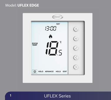
Model: UFLEX EDGE
UFLEX Series

2
Table of ContentsLocking/Unlocking the UFLEX EDGE
Holiday
Optional Settings Explained
Optional Settings - Feature Table
Adjusting the Optional Settings
Fail Safe/Modbus
Recalibrating the UFLEX EDGE
Error Codes
Wiring Diagrams
24
25
26-27
28
29
30
31
31
32-35
1
2
3-4
5-6
7
Product Image
Table of Contents
What is a Programmable Room Thermostat?
Installation Procedure
Mode Select
Mode 1 - Thermostat
LCD Display
Power On/OFF
Setting the Time & Date
Temperature Display
Pairing Accessories
View Accessories
Removing Accessories
Edit Comfort Levels
Temperature Control
Temperature Hold
Advance
Frost Protection
8
9-10
11
12
13
14-15
16
17
18-19
20
21
22
23
Mode 2 - Time Clock
LCD Display
Setting the Switching Times
Timer Advance
Timer Override
Optional Settings Explained
Optional Settings - Feature Table
Adjusting the Optional Settings
Replacing the Battery
36
37-38
39
40
40
41
41
42
43
UFLEX EDGE

3
What is a Programmable Room Thermostat?
A programmable room thermostat is both a programmer and a room thermostat.
A programmer allows you to set “On” and “O�” periods to suit your own lifestyle.
A room thermostat works by sensing the air temperature, switching on the heating when the air temperature falls below the thermostat setting, and switching it o� once this set temperature has been reached.
So a programmable room thermostat lets you choose what times you want the heating to be on, and what temperature it should reach while it is on. It will allow you to select di�erent temperatures in your home at di�erent times of the day (and days of the week) to meet your particular needs and preferences.
Setting a programmable room thermostat to a higher temperature will not make the room heat up any faster. How quickly the room heats up depends on the design and size of the heating system.
Similarly reducing the temperature setting does not a�ect how quickly the room cools down. Setting a programmable room thermostat to a lower temperature will result in the room being controlled at a lower temperature, and saves energy.
UFLEX Series

4
The way to set and use your programmable room thermostat is to �nd the lowest temperature settings that you are comfortable with at the di�erent times you have chosen, and then leave it alone to do its job.
The best way to do this is to set the room thermostat to a low temperature– say 18°C , and then turn it up by 1°C each day until you are comfortable with the temperature. You won’t have to adjust the thermostat further. Any adjustment above this setting will waste energy and cost you more money.
You are able to temporarily adjust the heating program by overriding or using the temperature hold feature. These features are explained further on pages 20 and 21 of this manual.
Programmable room thermostats need a free �ow of air to sense the temperature, so they must not be covered by curtains or blocked by furniture. Nearby electric �res, televisions, wall or table lamps may also prevent the thermostat from working properly.
UFLEX EDGE

5
Installation Procedure
This thermostat is designed to be �ush mounted and requires a back box of 35mm(minimum depth) to be sunk into the wall prior to installation.Step 1 Using a small screwdriver, slightly loosen the screw from the bottom face of the thermostat. You can then carefully separate the front half from the back plate.Step 2 Place the UFLEX EDGE LCD front plate somewhere safe. Terminate the thermostat as shown in the diagrams on page 32-35 of this booklet. Step 3 Screw the thermostat back plate securely into the back box.Step 4 Replace the front of the thermostat onto the back plate, by locating the pins in the socket then insert the top edge �rst. Now push in the bottom edge, securing it in place with the retaining screw.
DoMount the edge at eye level.Read the instructions fully so you get the best from our product.
Don’tDo not install near to a direct heat source as this will a�ect functionality. Do not push hard on the LCD screen as this may cause irreparable damage.
UFLEX Series

6
1 2
3 4
UFLEX EDGE
7
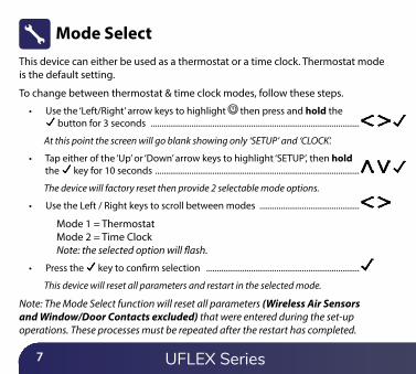
This device can either be used as a thermostat or a time clock. Thermostat mode is the default setting.
To change between thermostat & time clock modes, follow these steps.
• Use the ‘Left/Right’ arrow keys to highlight then press and hold the button for 3 seconds ..................................................................................................
At this point the screen will go blank showing only ‘SETUP’ and ‘CLOCK’.
• Tap either of the ‘Up’ or ‘Down’ arrow keys to highlight ‘SETUP’, then hold the key for 10 seconds ................................................................................................
The device will factory reset then provide 2 selectable mode options.
• Use the Left / Right keys to scroll between modes ...............................................
Mode 1 = Thermostat Mode 2 = Time Clock Note: the selected option will �ash.
• Press the key to con�rm selection ........................................................................
This device will reset all parameters and restart in the selected mode.
Note: The Mode Select function will reset all parameters (Wireless Air Sensors and Window/Door Contacts excluded) that were entered during the set-up operations. These processes must be repeated after the restart has completed.
Mode Select
UFLEX Series
8
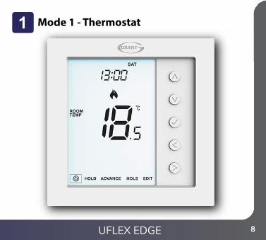
Mode 1 - Thermostat
UFLEX EDGE

9
5 61 2 3 4
78
9
10
1112
15
14
16
17
18
13
UFLEX Series
10
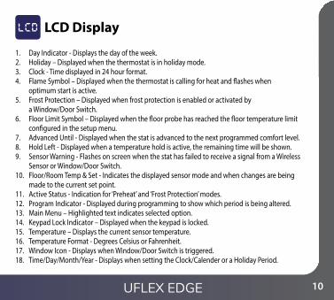
1. Day Indicator - Displays the day of the week.2. Holiday – Displayed when the thermostat is in holiday mode.3. Clock - Time displayed in 24 hour format.4. Flame Symbol – Displayed when the thermostat is calling for heat and �ashes when
optimum start is active.5. Frost Protection – Displayed when frost protection is enabled or activated by
a Window/Door Switch.6. Floor Limit Symbol – Displayed when the �oor probe has reached the �oor temperature limit
con�gured in the setup menu.7. Advanced Until - Displayed when the stat is advanced to the next programmed comfort level.8. Hold Left - Displayed when a temperature hold is active, the remaining time will be shown.9. Sensor Warning - Flashes on screen when the stat has failed to receive a signal from a Wireless
Sensor or Window/Door Switch.10. Floor/Room Temp & Set - Indicates the displayed sensor mode and when changes are being
made to the current set point.11. Active Status - Indication for ‘Preheat’ and ‘Frost Protection’ modes.12. Program Indicator - Displayed during programming to show which period is being altered.13. Main Menu – Highlighted text indicates selected option.14. Keypad Lock Indicator – Displayed when the keypad is locked.15. Temperature – Displays the current sensor temperature.16. Temperature Format - Degrees Celsius or Fahrenheit.17. Window Icon - Displays when Window/Door Switch is triggered.18. Time/Day/Month/Year - Displays when setting the Clock/Calender or a Holiday Period.
LCD Display
UFLEX EDGE

11
Power On/O�The heating is indicated ON when the �ame icon is displayed.
When the Flame Icon is absent, there is no requirement for heating to achieve theset temperature but the thermostat remains active.
To turn the thermostat o� completely, scroll to the Power Icon and hold the
key for approximately 3 seconds until the display goes blank .............................
The display and heating output will be turned OFF.
To turn the thermostat back ON, press the key once .......................................................................
Thermostat completely OFF Thermostat powered ON
UFLEX Series

12
Setting the Time and DateTo set the clock, follow these steps.
• Use the ‘Left/Right’ arrow keys to highlight then press and hold the
button for 3 seconds .............................................................................................
At this point the screen will go blank showing only ‘SETUP’ and ‘CLOCK’.
• Tap the ‘Up’ followed by ‘Right’ keys to highlight ‘CLOCK’ .............................
• Press to con�rm selection (‘Hour’ digits will now �ash) ...........................
• Use the ‘Up/Down’ arrow keys followed by to set the ‘Hours’ ................
• Use the ‘Up/Down’ arrow keys followed by to set the ‘Minutes’ ............
Repeat the previous two steps to set the date (‘Day, Month & Year’). Display will go blank once completed.
• Press the ‘Down’ arrow key followed by to return to the
main display ..................................................................................................................
UFLEX EDGE

13
This thermostat can be con�gured for di�erent sensor options such as built sensor, �oorsensor or both. The display will clearly indicate which sensor is being used by showingeither ‘ROOM TEMP’ or ‘FLOOR TEMP’ to the left the actual value.
When the thermostat is set to use both the air & the �oor sensor, the room temperaturewill be displayed by default.
To view the current �oor temperature, press and hold the Left and Right arrow keys for 5 seconds, the �oor temperature will then be displayed ..............................
Temperature Display
Room Temperature Floor Temperature
UFLEX Series
14
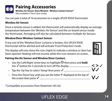
Pairing Accessories
You can pair a total of 16 accessories to a single UFLEX EDGE thermostat.
Wireless Air Sensor
Once a remote sensor is added, the thermostat will automatically display an average temperature between the ‘Wireless Air Sensor’ and the on-board sensor inside the thermostat. Averaging will also be calculated between multiple Air Sensors.
Window/Door Wireless Contact Sensor
If any one of the ‘Window/Door’ contacts is broken, the UFLEX EDGE thermostat will be alerted and will activate ‘Frost Protection’ mode.
The display will now show the icon (right) to indicate a window or door has been opened. Heating will not resume while this icon remains on screen.
Pairing the Air Sensor and Window/Door Contact.
• Use the ‘Left/Right’ arrow keys to highlight then press and hold the button for 3 seconds to turn o� the display .....................................
• Tap the ‘Up’ key to select ‘Setup’ then press ...............................................
• Press the ‘Down’ key until you see the letter ‘P’ displayed at the top of the screen then press .........................................................................................
Wireless Air Sensor. Door/Window - Wireless Contact Sensor*(Not available in Time Clock mode).
*Compatible accessories from Heatmiser UK Ltd.
UFLEX EDGE

15
If the sensor has successfully paired, the LED will go out after a few seconds. Thethermostat display will then show ‘01:P’ to indicate that the �rst accessory hasjoined. If countdown time elapses before all accessories have been paired,restart the countdown to add further sensors following the previous steps.
The thermostat will now start a 99 second countdown. During this time multiplesensors can be added.
Number of accessoriesconnected.
Pair/Reset button
Pair/Resetbutton
LED Indicator
Countdown time
• On the ‘Air Sensor & Window/Door Contact’, press and hold the pairing button for 5 seconds. The LED will glow red to indicate pairing status
Window/Door Wireless Contact Sensor Wireless Air Sensor
UFLEX Series

16
View Accessories• Use the ‘Left/Right’ arrow keys to highlight . Press and hold
for 3 seconds to turn o� the display ........................................................................
• Tap the ‘Up’ key to select ‘Setup’ then press ............................................................
• Press the ‘Down’ key until you see the letter ‘A’ displayed at the top of the screen, then press ....................................................................................................
• Use the ‘Left/Right’ arrow keys to scroll through the list of attached accessories.
A ‘Wireless Air Sensor’ will show the current temperature. The ‘Window/Door Contact’ will display current open or closed status by showing ‘OP’ = Open, or ‘CL’= Closed. If the ULFEX EDGE thermostat loses connection with an accessory, the display will show “--”.A battery warning symbol will be appear when an accessory reports low power.When this happens change the Lithium Cell CR2302 3V battery as soon as possible.
Example showing ‘Wireless Air Sensor’.
Accessory ID Number
Low Battery Warning
Current Status
UFLEX EDGE
17
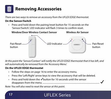
Removing Accessories
Pair/Resetbutton
Pair/Resetbutton
LED Indicator
There are two ways to remove an accessory from the UFLEX EDGE thermostat. On the Sensor/Switch
• Press and hold down the pairing/reset button for 15 seconds on the ‘Sensor/Switch’. LED indicator will �ash 3 times to con�rm reset.
At this point the ‘Sensor/Contact’ will notify the UFLEX EDGE thermostat that it has left, and will automatically be removed from the ‘Accessory Menu’. On the UFLEX EDGE thermostat
• Follow the steps on page 16 to enter the accessory menu.• Press the ‘Left/Right’ arrow keys to view the accessory that will be deleted.• Press and hold down the button for 10 seconds until the sensor
disappears from the menu ....................................................................................................Note: You will also need to reset the sensor at this point.
Window/Door Wireless Contact Sensor Wireless Air Sensor
UFLEX Series

18
Edit Comfort Levels
The UFLEX EDGE o�ers three program mode options; Weekday/Weekend, 7 Day and 24 Hour programming. There is also the option to use this device as a manual thermostat.
The thermostat is supplied with comfort levels already factory programmed, but these can be changed easily. The default times and temperature settings are;
07:00 - 21°C (Level 1) 09:00 - 16°C (Level 2) 16:00 - 21°C (Level 3) 22:00 - 16°C (Level 4)
Unused levels must be set to --:-- so that the device will skip these and continue on to the next programmed time.
For Weekday/Weekend programming, the four comfort levels are the same for Mon-Fri, but can be di�erent for Sat-Sun. For 7 Day programming each day of the week can have four di�erent comfort levels. In 24 Hour mode all days are programmed with the same comfort levels.
• To program the ‘Comfort Levels’, use the ‘Left/Right’ keys to scroll to ‘EDIT’ ......
• Press to con�rm selection ......................................................................................................
• Use the ‘Left/Right’ keys to select day/period of week (the selection will �ash) ......
• Press to con�rm selection ...................................................................................................... ‘Level 1’ will now �ash and the current time and temperature setting will be shown.
• Press to alter ‘Level 1’ settings ................................................................................................
UFLEX EDGE
19
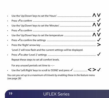
• Use the ‘Up/Down’ keys to set the ‘Hours’ .............................................................
• Press to con�rm .................................................................................................................
• Use the ‘Up/Down’ keys to set the ‘Minutes’ .........................................................
• Press to con�rm .................................................................................................................
• Use the ‘Up/Down’ keys to set the temperature .................................................
• Press to con�rm the settings ........................................................................................
• Press the ‘Right’ arrow key ..................................................................................................
‘Level 2’ will now �ash and the current settings will be displayed.
• Press to alter ‘Level 2’ settings ......................................................................................
Repeat these steps to set all comfort levels.
For any unused periods set time to --:--
• Use the ‘Left/Right’ keys to scroll to ‘DONE’ and press .........................
You can you set up to a maximum of 6 levels by enabling these in the feature menu (see page 28)
UFLEX Series

20
Temperature ControlThe ‘Up/Down’ keys allow you to adjust the set temperature ..............................
When you press either key, you will see the word ‘SET’ and the desiredtemperature value. Use the ‘Up/Down’ keys to adjust the ‘SET’ value ..............
Press to con�rm settings and return to the main display .....................................
Note: This new temperature is maintained only until the next programmed comfort level. At this time, the thermostat will revert back to the programmed levels.
Until next programmed‘Comfort Level’ time.
Set Temperature
UFLEX EDGE

21
Temperature HoldThe temperature hold function allows you to manually override the current operatingprogram and set a di�erent temperature for a desired period.
• Use the ‘Left/Right’ keys to scroll to ‘Hold’ and press ....................................• Repeatedly tap the ‘Up/Down’ keys to set the desired ‘Hold’ time
(Hours) then press ....................................................................................................Minutes will now �ash.
• Repeatedly tap the ‘Up/Down’ keys to set the desired ‘Hold’ time (Minutes) then press ...............................................................................................
• Use the ‘Up/Down’ keys to set the desired ‘Hold’ temperature .....................• Press to con�rm selection ..................................................................................................
You will see the ‘HOLD LEFT’ indication is displayed on screen. The time will countdown the set duration and then revert to the normal program.Cancel/Edit Temperature Hold
• Use the ‘Left/Right’ keys to scroll to ‘Hold’ and press ....................................• While ‘CANCEL’ is highlighted press to cancel ‘Hold’ and return to
normal operation .........................................................................................................................• Alternatively, press the ‘Left’ arrow key to highlight ‘EDIT’ them press
to adjust current ‘Hold’ settings ..................................................................................To edit ‘Hold’ settings follow the same procedure as indicated in the steps at the top of this page.
UFLEX Series

22
Advance
This feature allows the next ‘Comfort Level’ setting to be brought forward and beactive before its pre-programmed time.Note: Multiple advances aren’t allowed.
To enable ‘Advance’• Use the Left/Right keys to highlight ‘ADVANCE’ then press .................
‘ADVANCED UNTIL’ time and the ‘SET’ temperature will now be displayed.• Press again to con�rm selection ......................................................................................
To cancel ‘Advance’• Use the ‘Left/Right’ keys to highlight ‘Advance’ then press twice ........
• To view the ‘SET’ temperature during ‘Advance’ tap either the ‘ Up’ or ‘Down’ key once. Press to exit .................................
• To change the ‘SET’ temperature during ‘Advance’, use the ‘Up/Down’ keys followed by
to con�rm ...................................
‘Advanced Until’ time
UFLEX EDGE

23
Use the ‘Left/Right’ keys to scroll to the ‘Power Icon’ ...................................................
The frost icon will toggle ON/OFF each time is pressed ...........................................................
In this mode, the UFLEX EDGE will display the frost icon and will only turn the heating ‘ON’ should the room temperature drop below the set frost temperature. If the heating is turned ‘ON’ whilst in frost mode, the �ame symbol will be displayed.
To cancel the frost protect mode, navigate to the ‘Power Icon’ again, then press ..........
Frost Protection Symbol
Frost Protection
UFLEX Series
24
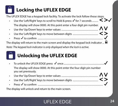
Locking the UFLEX EDGE The UFLEX EDGE has a keypad lock facility. To activate the lock follow these steps.
• Use the ‘Left/Right’ keys to scroll to Hold & press for 7 seconds ..........
The display will show 0000. At this point enter a four digit pin number.
• Use the ‘Up/Down’ keys to enter values .............................................................
• Use the ‘Left/Right’ keys to move between digits ..........................................
• Press to con�rm ............................................................................................................
The display will return to the main screen and display the keypad lock indicator ...
Note: The keypad lock indicator is only displayed when the lock is active.
• To unlock the UFLEX EDGE press once ........................................................................
The display will show 0000. At this point enter the four digit pin number you set previously.
• Use the ‘Up/Down’ keys to enter values .............................................................
• Use the ‘Left/Right’ keys to move between digits ..........................................
• Press to con�rm ............................................................................................................
The display will unlock and return to the main screen.
Unlocking the UFLEX EDGE
UFLEX EDGE
25
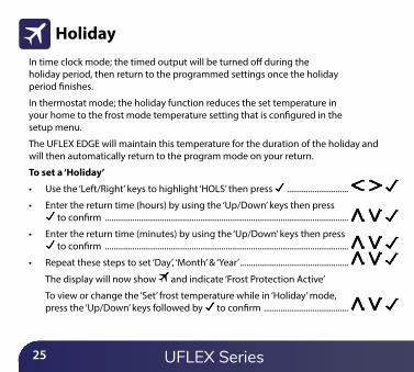
HolidayIn time clock mode; the timed output will be turned o� during the holiday period, then return to the programmed settings once the holiday period �nishes.
In thermostat mode; the holiday function reduces the set temperature in your home to the frost mode temperature setting that is con�gured in the setup menu.
The UFLEX EDGE will maintain this temperature for the duration of the holiday and will then automatically return to the program mode on your return.
To set a ‘Holiday’
• Use the ‘Left/Right’ keys to highlight ‘HOLS’ then press .............................
• Enter the return time (hours) by using the ‘Up/Down’ keys then press to con�rm ...................................................................................................................
• Enter the return time (minutes) by using the ‘Up/Down’ keys then press to con�rm ...................................................................................................................
• Repeat these steps to set ‘Day’, ‘Month’ & ‘Year’ ...................................................
The display will now show and indicate ‘Frost Protection Active’
To view or change the ‘Set’ frost temperature while in ‘Holiday’ mode, press the ‘Up/Down’ keys followed by to con�rm ........................................
UFLEX Series

26
Optional Settings ExplainedTHE FOLLOWING SETTINGS ARE OPTIONAL AND IN MOST CASES NEED NOT BE ADJUSTED.Viewing Accessories: Current status of each accessory, remote sensors and window switches.
Pairing Accessories: to a wireless room sensor or window switch.
Temperature Format: This function allows you to select between °C and °F.
Switching Di�erential: This function allows you to increase the switching di�erential of the thermostat. The default is 1°C which means that with a set temperature of 20°C, the thermostat will switch the heating on at 19°C and o� at 20°C. With a 2°C di�erential, the heating will switch on at 18°C and o� at 20°C. Condition: Whilst “Optimum Start” is in e�ect the ‘Switching Di�erential’ shall default to 1ºC/F
Output Delay: To prevent rapid switching, an output delay can be entered. This can be set from 00 - 15 minutes. The default is 00 which means there is no delay. Condition: Output delay will not be in e�ect while ‘Optimum Start’ is running.
Temperature Up/Down Limit: This function allows you to limit the use of the up and down keys. This limit is also applicable when the thermostat is locked and so allows limited control of the heating system.
Sensor Selection: On this thermostat, you can select which sensor should be used. You can select between air temperature only, �oor temperature, or both. When you enable both sensors, the �oor sensor is used as a �oor limiting sensor and is designed to prevent the �oor from overheating.
UFLEX EDGE

27
Floor Temp Limit: When the Floor Sensor has been enabled in feature 07, you can set a �oor limiting temperature between 20-45°C, this protects the �oor from overheating. (27°C is the default). Note: ‘Air Sensor Only’ MUST NOT be used to control electric under�oor heating. Floor Sensor or Both should be used.
Optimum Start: Optimum start will delay enabling of the heating system to the latest possible moment avoiding unnecessary heating and ensure the building has reached its desired temperature at the programmed time. The thermostat uses the rate of change information to calculate how long the heating needs to raise the building temperature 1°C.
Rate of Change: Number of minutes to raise the temperature by 1°C. Note: The user cannot change this feature and is for information only.
Programming Mode: The following program modes are available;
• Non-Programmable – Basic up/down override temperature control.
• 5/2 Day Programming – 4 levels for the weekdays and 4 di�erent levels for the weekend.
• 7 Day Programming – 4 levels for each day.
• 24 Hours – 4 levels over a 24 hour period.
Daylight Saving Time (DST): is where the thermostat sets the clocks forward one hour from ‘Standard Time’ during the summer months, and back again in autumn, in order to make better use of natural daylight.
Communications ID: To interface with building management systems using the standard Modbus protocol.
Program Type: You can select between 4 or 6 program/comfort levels.
UFLEX SeriesUFLEX Series
28
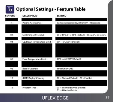
Optional Settings - Feature TableFEATURE
Viewing AccessoryPairing AccessoriesTemperature Format
Switching Di�erentialOutput DelayUp/Down Temperature LimitSensor Selection
Floor Temperature LimitOptimum Start
Rate of ChangeProgram Mode
(DST) Daylight SavingCommunications ID (Modbus)Program Type
DESCRIPTIONInformation only Commences countdown from 99 – 00 seconds.00 = °C, 01 = °F (00 = Default)
00 = 0.5°C, 01 = 1.0°C (Default) 02 = 2.0°C, 03 = 3.0°C00 - 15 Minutes (00 = Default)00° - 10°C (00° = Default)00 = Built in Sensor with optional Remote Air (Default) 01 = Remoter Air Only 02 = Floor Sensor Only 03 = Built in + Floor Sensor + optional Remote Air 04 = Remote Air & Floor Sensor Only20°C – 45°C (28°C Default)00 = Disabled (Default) 01 = 1 Hour 02 = 2 Hours 03 = 3 Hours 04 = 4 Hours 05 = 5 HoursInformation Only00 = 5/2 01 = 7 Day 02 = 24 Hour 03 = None programmable00 = Disabled (Default) 01 = Enabled01-32 00 = Disabled00 = 4 Comfort Levels (Default) 01 = 6 Comfort Levels
SETTINGAP
01 Menu
Entry Point 02030405
0607
0809
1011
12
UFLEX EDGE

29
Adjusting the Optional Settings• Use the ‘Left/Right’ arrow keys to highlight then press and hold the
button for 3 seconds .............................................................................................
The display will go blank showing only ‘Setup’ and ‘Clock’
• Press the ‘Up’ key followed by twice to access main feature menu .......
• Use the ‘Up/Down’ keys to scroll through features ..........................................
• Use the ‘Left/Right’ keys to change feature setting ..........................................
• When all required changes have been made press to con�rm settings and return to the blank display .......................................................................................
• Use the ‘Down’ key to select then press once to power on ...............
Feature Setting
Feature No.
UFLEX Series

30
Fail SafeIf the thermostats on board sensor is disabled and is reliant on a single wireless remote sensor for temperature measurement, failsafe will activate if connection is lost.
• From the moment ‘E2’ is displayed on screen, failsafe will become active.• Approximately 12 minutes later the thermostat will enable the heat source for
an initial 12 minute period and then repeat every hour.• Failsafe will continue until the thermostat re-establishes connection to
the remote sensor.
ModbusModbus interface allows the thermostat to be controlled via home automation or a building management system.
• A maximum of 32 devices can be connected to a single RS485 adapter.• It is recommended that a foil twisted pair (FTP) cable is used for the
Modbus connections.• All Modbus connections should be daisy chained
rather than wired in a star formation.• If the UFLEX EDGE is the last Modbus device
on the end of the chain, move the toggle switch on the back of the fascia to the ‘On’ position.
Fascia PCB
UFLEX EDGE

31
Re-calibrating the UFLEX EDGEThis thermostat is factory set and need not re-calibrating under normal operation!To calibrate, follow the step below.
• Use the ‘Left/Right’ keys to scroll to the Power Icon ...................................• Press and hold to turn the display ‘OFF’ .............................................................• Press and hold the and ‘Down’ keys together for 10 seconds ....................
The current temperature will appear on the display.• Use the ‘Up/Down’ keys to con�gure the new temperature value ...............• Press the key to con�rm the change and the display will go blank .........• Press the key once to turn the thermostat ‘ON’ ............................................ ...
Error Codes
E0 = The internal sensor has developed a fault.E1 = The remote FLOOR probe has not been connected. The remote FLOOR probe has not been wired correctly.
The remote FLOOR probe is faulty. E2 = The WIRELESS AIR SENSOR has not been paired correctly.
The WIRELESS AIR SENSOR has lost connection to the edge. (check batteries). The remote WIRELESS AIR SENSOR is faulty.
The UFLEX EDGE will display an error code if there is a fault with the temperaturesensor, these error codes are explained below.
UFLEX Series
32
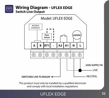
Wiring Diagram - UFLEX EDGE
NEUTRAL
MODBUSINTERFACE
Model: UFLEX EDGE
LIVE
230V SUPPLY IN
SWITCHED LIVE TO BOILER
230VAC
RT1 - A2 A1 N LBA
This product must only be installed by a quali�ed electrician and comply with local installation regulations.
FloorSensor
Switch Live Output
UFLEX EDGE

33
Wiring Diagram - UFLEX EDGE Volt Free Output (Thermostat & Time Clock Modes)
NEUTRALLS & LR ARE NORMALLY THEROOM THERMOSTAT CONNECTIONS
MODBUSINTERFACE
LIVE
230V SUPPLY INVOLT FREE TO BOILER
230VAC
RT1 - A2 A1 N LBA
This product must only be installed by a quali�ed electrician and comply with local installation regulations.
FloorSensor
LS
LR
UFLEX Series
Model: UFLEX EDGE

34
NEUTRALNEUTRAL
LIVE230V SUPPLY IN
HEATING VALVE
TO BOILER
This product must only be installed by a quali�ed electrician and comply with local installation regulations.
MODBUSINTERFACE
230VAC
RT1 - A2 A1 N LBA
FloorSensor
Wiring Diagram - UFLEX EDGE to Valve
LS & LR ARE NORMALLY THEROOM THERMOSTAT CONNECTIONS
TO CONNECT BOILER CONSULTBOILER MANUFACTURERSDIAGRAM
LS LNLR
Model: UFLEX EDGE
UFLEX EDGE
35
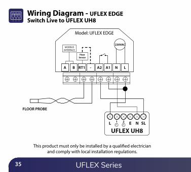
Wiring Diagram - UFLEX EDGE
This product must only be installed by a quali�ed electrician and comply with local installation regulations.
MODBUSINTERFACE
230VAC
RT1 - A2 A1 N LBA
FLOOR PROBE
NE SLL 1 2
UFLEX UH8
FloorSensor
UFLEX Series
Model: UFLEX EDGE
Switch Live to UFLEX UH8

36
Mode 2 - Time Clock
UFLEX EDGE

37
1 2 3
6
54
79
10
8
11
UFLEX Series
38
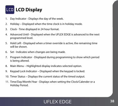
1. Day Indicator - Displays the day of the week.
2. Holiday – Displayed when the time clock is in holiday mode.
3. Clock - Time displayed in 24 hour format.
4. Advanced Until - Displayed when the UFLEX EDGE is advanced to the next programmed level.
5. Hold Left - Displayed when a timer override is active, the remaining time will be shown.
6. Set - Indicates when changes are being made.
7. Program Indicator - Displayed during programming to show which period is being altered.
8. Main Menu – Highlighted display indicates selected option.
9. Keypad Lock Indicator – Displayed when the keypad is locked.
10. Timer Status – Displays the current status of the timed output.
11. Time/Day/Month/Year - Displays when setting the Clock/Calender or a Holiday Period.
LCD Display
UFLEX EDGE

39
Setting the Switching TimesTo program the switching times, follow these steps.
• Use the ‘Left/Right’ keys to scroll to ‘EDIT’ ..........................................................................• Press to con�rm selection ...................................................................................................• Use the ‘Up/Down’ keys to select the day/period to program ............................• Press to con�rm selection ...................................................................................................• Level ‘1’ will now be highlighted and the ‘ON’ time will be displayed.• Press to alter Level ‘1’ ............................................................................................................• To set the ‘ON’ time, use the ‘Up/Down’ keys to set the hours,
followed by , then use ‘Up/Down’ to set the minutes ..................• Press to con�rm ......................................................................................................................• To set the ‘OFF’ time, use the ‘Up/Down’ keys to set the hours,
followed by , then use ‘Up/Down’ to set the minutes ..................• Press to con�rm the settings .............................................................................................• Press the ‘Right’ arrow key .......................................................................................................• Level ‘2’ will now be highlighted and the current settings will be displayed.• Press to alter Level ‘2’ settings ...........................................................................................• Repeat these steps to set all periods.• To blank or set a switching level period to unused, �rst select the switching level
then set --:-- in place of the time.• When all switching times have been programmed use the ‘Right’ arrow
key to highlight ‘DONE’ and press .............................................................................
UFLEX Series

40
AdvanceTime Remaining
Output Status
LevelAdvanced Until
Timer AdvanceTo boost the timed output ‘ON’ follow these steps.
• Use the ‘Left/Right’ keys to highlight ‘Advance’ then press twice ...... Boost Left and the remaining time will now be displayed.
To cancel ‘Advance’• While ‘ADVANCE’ is highlighted
press twice .............................
To override the timed output ‘ON/OFF’, follow these steps.
• Use the ‘Left/Right’ keys to highlight ‘HOLD’ then press ..............................• Use the ‘Up/Down’ keys to set the hours then press .....................................
• Use the ‘Up/Down’ keys to set the minutes then press ................................• Use the ‘Up/Down’ keys to set output On or OFF then press to con�rm ....
Hold Left and the remaining time will now be displayed.To cancel Timer Override
• With ‘HOLD’ highlighted, press twice ...................................................................
Timer Override
UFLEX EDGE

41
Optional Settings - Feature Table
Optional Settings ExplainedProgramming Mode: The following program modes are available;
5/2 Day Programming - 4 On/O� switching times for the weekdays and 4 On/O� switching times for the weekend.7 Day Programming - 4 individual On/O� switching times for each day.24 Hours - 4 On/O� switching times over a 24 hour period.
Daylight Saving Time (DST): is where the thermostat sets the clocks forward onehour from Standard Time during the summer months, and back again in autumn, inorder to make better use of natural daylight.
Communications ID: To interface with building management systems using thestandard Modbus protocol.
FEATURE SETTING
Program Mode 00 = 5/2 (Default),01 = 7 Day,02 = 24 Hour
Daylight Saving Time (DST) 00 = Disabled (Default) 01 = Enabled
Communications ID 01-32 00 = Disabled)
UFLEX Series
42
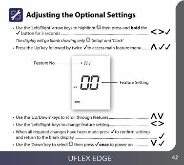
Adjusting the Optional Settings• Use the ‘Left/Right’ arrow keys to highlight then press and hold the
button for 3 seconds .............................................................................................
The display will go blank showing only ‘Setup’ and ‘Clock’
• Press the ‘Up’ key followed by twice to access main feature menu .......
• Use the ‘Up/Down’ keys to scroll through features ..........................................
• Use the ‘Left/Right’ keys to change feature setting ..........................................
• When all required changes have been made press to con�rm settings and return to the blank display .......................................................................................
• Use the ‘Down’ key to select then press once to power on ...............
Feature Setting
Feature No.
UFLEX EDGE

43
Replacing the Battery
In most cases the 3 volt lithium battery does not need replacing if the thermostat has a continual power supply. Its sole purpose is to ensure correct time keeping during a power loss to the thermostat.
To remove the battery use a small �at head screw driver or �ngertip to push back the brass retaining bracket. This will automatically release the battery.
Insert the new battery (positive side up!) by locating one end underneath the holding clips then pushing down on the opposite end against the brass retaining bracket.
Holding clips
Brass retaining bracket
We advise that replacement of the lithium battery be carried out by a quali�ed professional.
UFLEX Series

.........................................................................................................................................................................
.........................................................................................................................................................................
.........................................................................................................................................................................
.........................................................................................................................................................................
.........................................................................................................................................................................
.........................................................................................................................................................................
.........................................................................................................................................................................
.........................................................................................................................................................................
.........................................................................................................................................................................
.........................................................................................................................................................................
.........................................................................................................................................................................
.........................................................................................................................................................................
.........................................................................................................................................................................
44
Notes
UFLEX EDGE

45 UFLEX Series
.........................................................................................................................................................................
.........................................................................................................................................................................
.........................................................................................................................................................................
.........................................................................................................................................................................
.........................................................................................................................................................................
.........................................................................................................................................................................
.........................................................................................................................................................................
.........................................................................................................................................................................
.........................................................................................................................................................................
.........................................................................................................................................................................
.........................................................................................................................................................................
.........................................................................................................................................................................
.........................................................................................................................................................................
Notes

46
.........................................................................................................................................................................
.........................................................................................................................................................................
.........................................................................................................................................................................
.........................................................................................................................................................................
.........................................................................................................................................................................
.........................................................................................................................................................................
.........................................................................................................................................................................
.........................................................................................................................................................................
.........................................................................................................................................................................
.........................................................................................................................................................................
.........................................................................................................................................................................
.........................................................................................................................................................................
.........................................................................................................................................................................
Notes
UFLEX EDGE

Rev. 1.0
Want More Information?
ROI: Call 0579120089 or visit www.grantengineering.ie
NI: Call 0800 2794796 or visit www.grantni.com
G.B. (England, Scotland and Wales): Call 01380 736920 or visit www.grantuk.com