GR00003800-11A
66
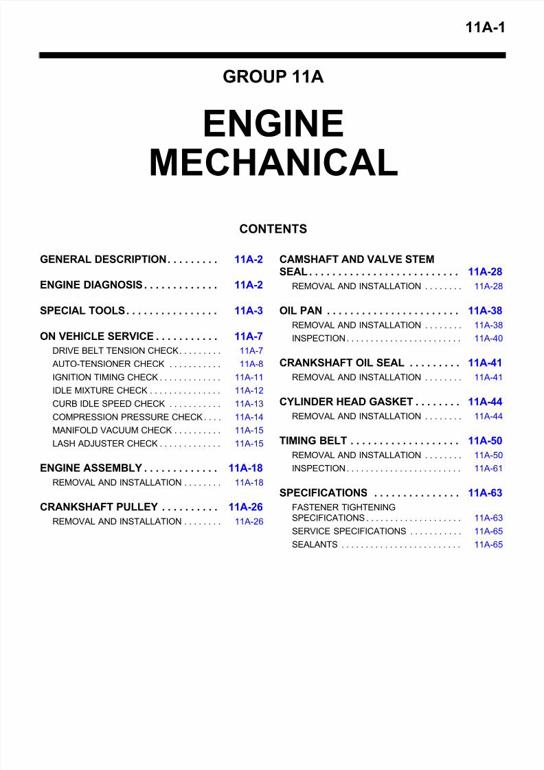
11A-1 GROUP 11A ENGINE MECHANICAL CONTENTS GENERAL DESCRIPTION . . . . . . . . . 11A-2 ENGINE DIAGNOSIS . . . . . . . . . . . . . 11A-2 SPECIAL TOOLS . . . . . . . . . . . . . . . . 11A-3 ON VEHICLE SERVICE . . . . . . . . . . . 11A-7 DRIVE BELT TENSION CHECK . . . . . . . . . 11A-7 AUTO-TENSIONER CHECK . . . . . . . . . . . 11A-8 IGNITION TIMING CHECK . . . . . . . . . . . . . 11A-11 IDLE MIXTURE CHECK . . . . . . . . . . . . . . . 11A-12 CURB IDLE SPEED CHECK . . . . . . . . . . . 11A-13 COMPRESSION PRESSURE CHECK . . . . 11A-14 MANIFOLD VACUUM CHECK . . . . . . . . . . 11A-15 LASH ADJUSTER CHECK . . . . . . . . . . . . . 11A-15 ENGINE ASSEMBLY . . . . . . . . . . . . . 11A-18 REMOVAL AND INSTALLATION . . . . . . . . 11A-18 CRANKSHAFT PULLEY . . . . . . . . . . 11A-26 REMOVAL AND INSTALLATION . . . . . . . . 11A-26 CAMSHAFT AND VALVE STEM SEAL . . . . . . . . . . . . . . . . . . . . . . . . . . 11A-28 REMOVAL AND INSTALLATION . . . . . . . . 11A-28 OIL PAN . . . . . . . . . . . . . . . . . . . . . . . 11A-38 REMOVAL AND INSTALLATION . . . . . . . . 11A-38 INSPECTION . . . . . . . . . . . . . . . . . . . . . . . . 11A-40 CRANKSHAFT OIL SEAL . . . . . . . . . 11A-41 REMOVAL AND INSTALLATION . . . . . . . . 11A-41 CYLINDER HEAD GASKET . . . . . . . . 11A-44 REMOVAL AND INSTALLATION . . . . . . . . 11A-44 TIMING BELT . . . . . . . . . . . . . . . . . . . 11A-50 REMOVAL AND INSTALLATION . . . . . . . . 11A-50 INSPECTION . . . . . . . . . . . . . . . . . . . . . . . . 11A-61 SPECIFICATIONS . . . . . . . . . . . . . . . 11A-63 FASTENER TIGHTENING SPECIFICATIONS . . . . . . . . . . . . . . . . . . . . 11A-63 SERVICE SPECIFICATIONS . . . . . . . . . . . 11A-65 SEALANTS . . . . . . . . . . . . . . . . . . . . . . . . . 11A-65
-
Upload
mohamed-bakheet -
Category
Documents
-
view
215 -
download
0
Transcript of GR00003800-11A
8/8/2019 GR00003800-11A
http://slidepdf.com/reader/full/gr00003800-11a 1/66
11A-1
GROUP 11A
ENGINEMECHANICAL
CONTENTS
GENERAL DESCRIPTION. . . . . . . . . 11A-2
ENGINE DIAGNOSIS. . . . . . . . . . . . . 11A-2
SPECIAL TOOLS. . . . . . . . . . . . . . . . 11A-3
ON VEHICLE SERVICE. . . . . . . . . . . 11A-7
DRIVE BELT TENSION CHECK. . . . . . . . . 11A-7
AUTO-TENSIONER CHECK . . . . . . . . . . . 11A-8
IGNITION TIMING CHECK. . . . . . . . . . . . . 11A-11
IDLE MIXTURE CHECK . . . . . . . . . . . . . . . 11A-12
CURB IDLE SPEED CHECK . . . . . . . . . . . 11A-13COMPRESSION PRESSURE CHECK. . . . 11A-14
MANIFOLD VACUUM CHECK . . . . . . . . . . 11A-15
LASH ADJUSTER CHECK . . . . . . . . . . . . . 11A-15
ENGINE ASSEMBLY. . . . . . . . . . . . . 11A-18
REMOVAL AND INSTALLATION . . . . . . . . 11A-18
CRANKSHAFT PULLEY . . . . . . . . . . 11A-26
REMOVAL AND INSTALLATION . . . . . . . . 11A-26
CAMSHAFT AND VALVE STEM
SEAL. . . . . . . . . . . . . . . . . . . . . . . . . . 11A-28REMOVAL AND INSTALLATION . . . . . . . . 11A-28
OIL PAN . . . . . . . . . . . . . . . . . . . . . . . 11A-38
REMOVAL AND INSTALLATION . . . . . . . . 11A-38
INSPECTION. . . . . . . . . . . . . . . . . . . . . . . . 11A-40
CRANKSHAFT OIL SEAL . . . . . . . . . 11A-41
REMOVAL AND INSTALLATION . . . . . . . . 11A-41
CYLINDER HEAD GASKET . . . . . . . . 11A-44REMOVAL AND INSTALLATION . . . . . . . . 11A-44
TIMING BELT . . . . . . . . . . . . . . . . . . . 11A-50
REMOVAL AND INSTALLATION . . . . . . . . 11A-50
INSPECTION. . . . . . . . . . . . . . . . . . . . . . . . 11A-61
SPECIFICATIONS . . . . . . . . . . . . . . . 11A-63
FASTENER TIGHTENING
SPECIFICATIONS. . . . . . . . . . . . . . . . . . . . 11A-63
SERVICE SPECIFICATIONS . . . . . . . . . . . 11A-65
SEALANTS . . . . . . . . . . . . . . . . . . . . . . . . . 11A-65
8/8/2019 GR00003800-11A
http://slidepdf.com/reader/full/gr00003800-11a 2/66
GENERAL DESCRIPTION
TSB Revision
ENGINE MECHANICAL11A-2
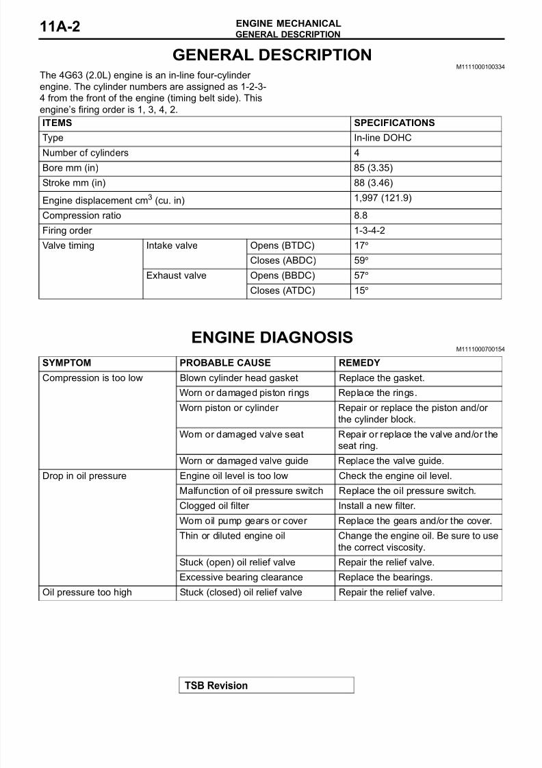
GENERAL DESCRIPTIONM1111000100334
The 4G63 (2.0L) engine is an in-line four-cylinder
engine. The cylinder numbers are assigned as 1-2-3-
4 from the front of the engine (timing belt side). This
engine’s firing order is 1, 3, 4, 2.
ENGINE DIAGNOSISM1111000700154
ITEMS SPECIFICATIONS
Type In-line DOHC
Number of cylinders 4
Bore mm (in) 85 (3.35)
Stroke mm (in) 88 (3.46)
Engine displacement cm3 (cu. in) 1,997 (121.9)
Compression ratio 8.8
Firing order 1-3-4-2
Valve timing Intake valve Opens (BTDC) 17°
Closes (ABDC) 59°
Exhaust valve Opens (BBDC) 57°
Closes (ATDC) 15°
SYMPTOM PROBABLE CAUSE REMEDY
Compression is too low Blown cylinder head gasket Replace the gasket.
Worn or damaged piston rings Replace the rings.
Worn piston or cylinder Repair or replace the piston and/or
the cylinder block.
Worn or damaged valve seat Repair or replace the valve and/or the
seat ring.
Worn or damaged valve guide Replace the valve guide.
Drop in oil pressure Engine oil level is too low Check the engine oil level.
Malfunction of oil pressure switch Replace the oil pressure switch.
Clogged oil filter Install a new filter.
Worn oil pump gears or cover Replace the gears and/or the cover.
Thin or diluted engine oil Change the engine oil. Be sure to usethe correct viscosity.
Stuck (open) oil relief valve Repair the relief valve.
Excessive bearing clearance Replace the bearings.
Oil pressure too high Stuck (closed) oil relief valve Repair the relief valve.
8/8/2019 GR00003800-11A
http://slidepdf.com/reader/full/gr00003800-11a 3/66
SPECIAL TOOLS
TSB Revision
ENGINE MECHANICAL 11A-3
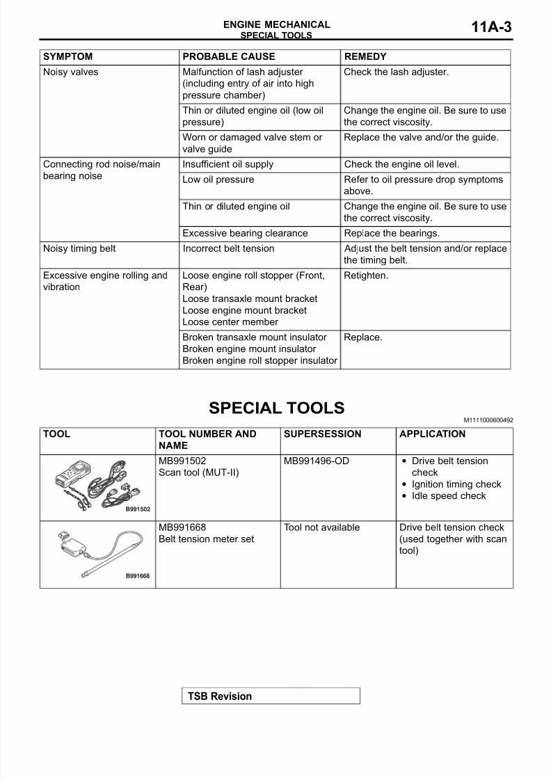
SPECIAL TOOLS M1111000600492
Noisy valves Malfunction of lash adjuster
(including entry of air into high
pressure chamber)
Check the lash adjuster.
Thin or diluted engine oil (low oil
pressure)
Change the engine oil. Be sure to use
the correct viscosity.
Worn or damaged valve stem or valve guide
Replace the valve and/or the guide.
Connecting rod noise/main
bearing noise
Insufficient oil supply Check the engine oil level.
Low oil pressure Refer to oil pressure drop symptoms
above.
Thin or diluted engine oil Change the engine oil. Be sure to use
the correct viscosity.
Excessive bearing clearance Replace the bearings.
Noisy timing belt Incorrect belt tension Adjust the belt tension and/or replace
the timing belt.
Excessive engine rolling andvibration
Loose engine roll stopper (Front,Rear)
Loose transaxle mount bracket
Loose engine mount bracket
Loose center member
Retighten.
Broken transaxle mount insulator
Broken engine mount insulator
Broken engine roll stopper insulator
Replace.
SYMPTOM PROBABLE CAUSE REMEDY
TOOL TOOL NUMBER AND
NAME
SUPERSESSION APPLICATION
MB991502
Scan tool (MUT-II)
MB991496-OD • Drive belt tension
check
• Ignition timing check
• Idle speed check
MB991668
Belt tension meter set
Tool not available Drive belt tension check
(used together with scan
tool)
B991502
B991668
8/8/2019 GR00003800-11A
http://slidepdf.com/reader/full/gr00003800-11a 4/66
SPECIAL TOOLS
TSB Revision
ENGINE MECHANICAL11A-4
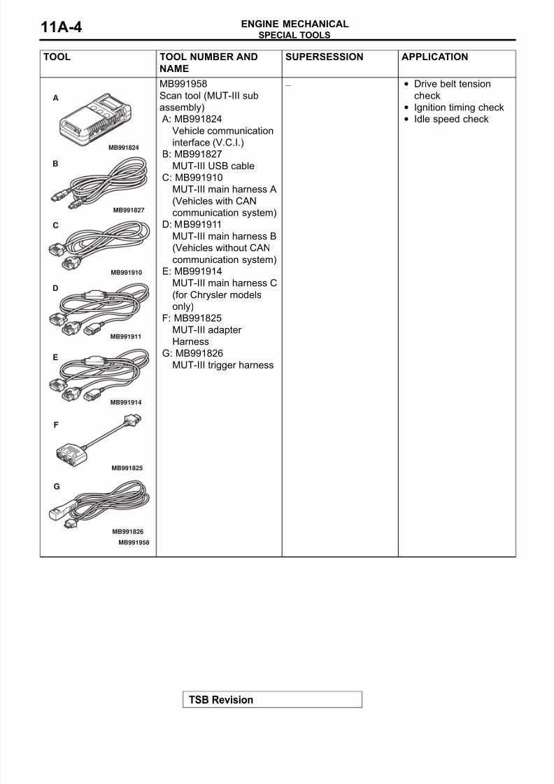
MB991958
Scan tool (MUT-III sub
assembly)
A: MB991824
Vehicle communication
interface (V.C.I.)
B: MB991827
MUT-III USB cable
C: MB991910
MUT-III main harness A
(Vehicles with CAN
communication system)
D: MB991911
MUT-III main harness B
(Vehicles without CAN
communication system)
E: MB991914MUT-III main harness C
(for Chrysler models
only)
F: MB991825
MUT-III adapter
Harness
G: MB991826
MUT-III trigger harness
− • Drive belt tension
check
• Ignition timing check
• Idle speed check
TOOL TOOL NUMBER AND
NAME
SUPERSESSION APPLICATION
MB991910
MB991826
MB991958
MB991911
MB991914
MB991824
MB991827
MB991825
A
B
C
D
E
F
G
8/8/2019 GR00003800-11A
http://slidepdf.com/reader/full/gr00003800-11a 5/66
SPECIAL TOOLS
TSB Revision
ENGINE MECHANICAL 11A-5
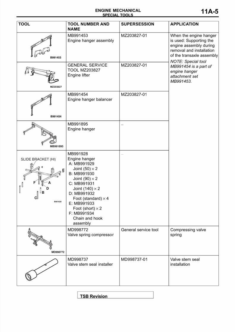
MB991453
Engine hanger assembly
MZ203827-01 When the engine hanger
is used: Supporting the
engine assembly during
removal and installation
of the transaxle assembly
NOTE: Special tool
MB991454 is a part of
engine hanger
attachment set
MB991453.
GENERAL SERVICE
TOOL MZ203827
Engine lifter
MZ203827-01
MB991454
Engine hanger balancer
MZ203827-01
MB991895
Engine hanger −
MB991928
Engine hanger
A: MB991929
Joint (50) × 2
B: MB991930Joint (90) × 2
C: MB991931
Joint (140) × 2
D: MB991932
Foot (standard) × 4
E: MB991933
Foot (short) × 2
F: MB991934
Chain and hook
assembly
−
MD998772
Valve spring compressor
General service tool Compressing valve
spring
MD998737
Valve stem seal installer
MD998737-01 Valve stem seal
installation
TOOL TOOL NUMBER AND
NAME
SUPERSESSION APPLICATION
B991453
MZ203827
B991454
MB991895
B991928
A
B
C
D
E
F
SLIDE BRACKET (HI)
MD998772
8/8/2019 GR00003800-11A
http://slidepdf.com/reader/full/gr00003800-11a 6/66
SPECIAL TOOLS
TSB Revision
ENGINE MECHANICAL11A-6
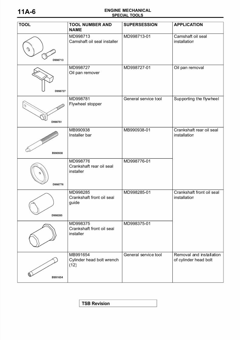
MD998713
Camshaft oil seal installer
MD998713-01 Camshaft oil seal
installation
MD998727
Oil pan remover
MD998727-01 Oil pan removal
MD998781
Flywheel stopper
General service tool Supporting the flywheel
MB990938
Installer bar
MB990938-01 Crankshaft rear oil seal
installation
MD998776
Crankshaft rear oil seal
installer
MD998776-01
MD998285
Crankshaft front oil seal
guide
MD998285-01 Crankshaft front oil seal
installation
MD998375
Crankshaft front oil seal
installer
MD998375-01
MB991654
Cylinder head bolt wrench
(12)
General service tool Removal and installation
of cylinder head bolt
TOOL TOOL NUMBER AND
NAME
SUPERSESSION APPLICATION
D998713
D998727
D998781
B990938
D998776
D998285
B991654
8/8/2019 GR00003800-11A
http://slidepdf.com/reader/full/gr00003800-11a 7/66
ON VEHICLE SERVICE
TSB Revision
ENGINE MECHANICAL 11A-7
ON VEHICLE SERVICE
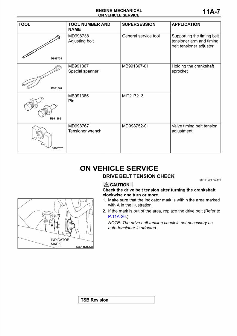
DRIVE BELT TENSION CHECK M1111003100344
CAUTION
Check the drive belt tension after turning the crankshaft
clockwise one turn or more.
1. Make sure that the indicator mark is within the area marked
with A in the illustration.
2. If the mark is out of the area, replace the drive belt (Refer to
P.11A-26.)
NOTE: The drive belt tension check is not necessary as
auto-tensioner is adopted.
MD998738
Adjusting bolt
General service tool Supporting the timing belt
tensioner arm and timing
belt tensioner adjuster
MB991367
Special spanner
MB991367-01 Holding the crankshaft
sprocket
MB991385
Pin
MIT217213
MD998767
Tensioner wrench
MD998752-01 Valve timing belt tension
adjustment
TOOL TOOL NUMBER AND
NAME
SUPERSESSION APPLICATION
D998738
B991367
B991385
D998767
AC211616AB
A
INDICATOR
MARK
8/8/2019 GR00003800-11A
http://slidepdf.com/reader/full/gr00003800-11a 8/66
ON VEHICLE SERVICE
TSB Revision
ENGINE MECHANICAL11A-8
AUTO-TENSIONER CHECKM1111003000121
OPERATION CHECK
1. Turn OFF the engine from the idle state then check to see
that the drive belt is not protruding from the pulley width of
the auto-tensioner.
2. Remove the drive belt.(Refer to P.11A-26.)
3. Securely insert the spindle handle or ratchet handle with a12.7mm (1/2-inch) insertion angle into the jig hole of the
auto tensioner. Turn the auto-tensioner to the left and right
to check and see that there is no threading.
4. If there are any problems in the procedure 1 or 3, replace
the auto-tensioner.(Refer to P.11A-50.)
5. Install the drive belt.(Refer to P.11A-26.)
FUNCTION CHECK
You can verify if the auto-tensioner is defective or not by check-
ing the drive belt tension..
When using scan tool MB991502
Required Special Tools:
• MB991502: Scan Tool (MUT-II)
• MB991668: Belt Tension Meter Set
1. Check the drive belt tension. (Refer to P.11A-26.)
2. Measure the drive belt tension vibration frequency by the
following procedures:
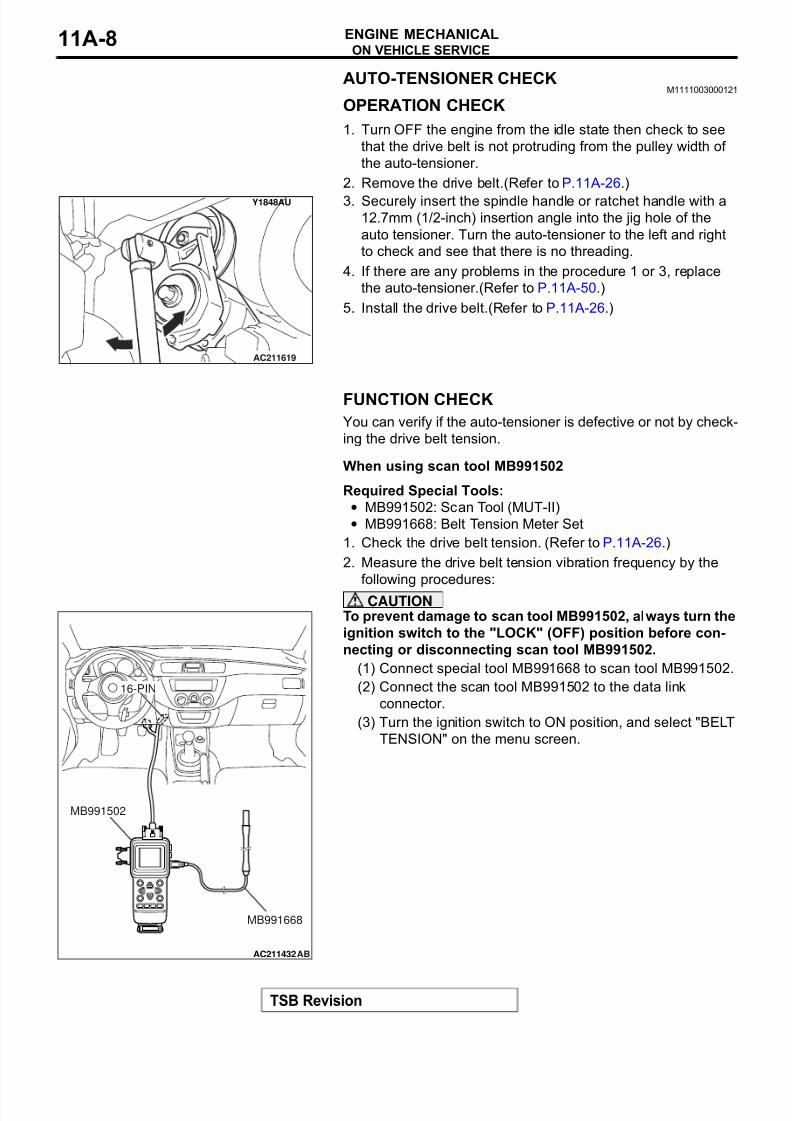
CAUTIONTo prevent damage to scan tool MB991502, always turn the
ignition switch to the "LOCK" (OFF) position before con-
necting or disconnecting scan tool MB991502.
(1) Connect special tool MB991668 to scan tool MB991502.
(2) Connect the scan tool MB991502 to the data link
connector.
(3) Turn the ignition switch to ON position, and select "BELT
TENSION" on the menu screen.
Y1848AU
AC211619
AC211432
16-PIN
AB
MB991502
MB991668
8/8/2019 GR00003800-11A
http://slidepdf.com/reader/full/gr00003800-11a 9/66
ON VEHICLE SERVICE
TSB Revision
ENGINE MECHANICAL 11A-9
CAUTION
• The temperature of the surface of the belt should be as
close to normal temperature as possible.
• Do not allow any contaminants such as water or oil to
get onto the microphone.
• If strong gusts of wind blow against the microphone or
if there are any loud sources of noise nearby, the val-
ues measured by the microphone may not correspond
to actual values.
• If the microphone is touching the belt while the mea-
surement is being made, the values measured by the
microphone may not correspond to actual values.
• Do not take the measurement while the vehicle's engine
is running.
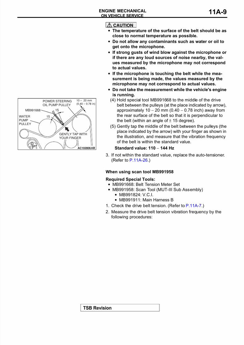
(4) Hold special tool MB991668 to the middle of the drive
belt between the pulleys (at the place indicated by arrow),
approximately 10 − 20 mm (0.40 − 0.78 inch) away from
the rear surface of the belt so that it is perpendicular to
the belt (within an angle of ± 15 degree).(5) Gently tap the middle of the belt between the pulleys (the
place indicated by the arrow) with your finger as shown in
the illustration, and measure that the vibration frequency
of the belt is within the standard value.
Standard value: 110 − 144 Hz
3. If not within the standard value, replace the auto-tensioner.
(Refer to P.11A-26.)
.
When using scan tool MB991958
Required Special Tools:• MB991668: Belt Tension Meter Set
• MB991958: Scan Tool (MUT-III Sub Assembly)
• MB991824: V.C.I.
• MB991911: Main Harness B
1. Check the drive belt tension. (Refer to P.11A-7.)
2. Measure the drive belt tension vibration frequency by the
following procedures:
AC102806AB
MB991668
15˚
15˚
GENTLY TAP WITH
YOUR FINGER
WATER
PUMPPULLEY
POWER STEERING
OIL PUMP PULLEY
10 – 20 mm
(0.40 – 0.78 in)
8/8/2019 GR00003800-11A
http://slidepdf.com/reader/full/gr00003800-11a 10/66
ON VEHICLE SERVICE
TSB Revision
ENGINE MECHANICAL11A-10
CAUTIONTo prevent damage to scan tool MB991824, always turn the
ignition switch to the "LOCK" (OFF) position before con-
necting or disconnecting scan tool MB991824.
(1) Connect special tool MB991668 to scan tool MB991824.
(2) Connect scan tool MB991911 to scan tool MB991824.
(3) Connect scan tool MB991911 to the data link connector.
(4) Turn the ignition switch to the "ON" position and select
"Belt Tension Measurement" from the menu scan tool
MB991824 screen.
CAUTION
• The temperature of the surface of the belt should be as
close to normal temperature as possible.
• Do not allow any contaminants such as water or oil to
get onto the microphone.
• If strong gusts of wind blow against the microphone or
if there are any loud sources of noise nearby, the val-
ues measured by the microphone may not correspond
to actual values.
• If the microphone is touching the belt while the mea-
surement is being made, the values measured by the
microphone may not correspond to actual values.
• Do not take the measurement while the vehicle's engine
is running.
(5) Hold special tool MB991668 to the middle of the drive
belt between the pulleys (at the place indicated by arrow),
approximately 10 − 20 mm (0.40 − 0.78 inch) away from
the rear surface of the belt so that it is perpendicular to
the belt (within an angle of ± 15 degree).
(6) Gently tap the middle of the belt between the pulleys (theplace indicated by the arrow) with your finger as shown in
the illustration, and measure that the vibration frequency
of the belt is within the standard value.
Standard value: 110 − 144 Hz
3. If not within the standard value, replace the auto-tensioner.
(Refer to P.11A-50.)
.
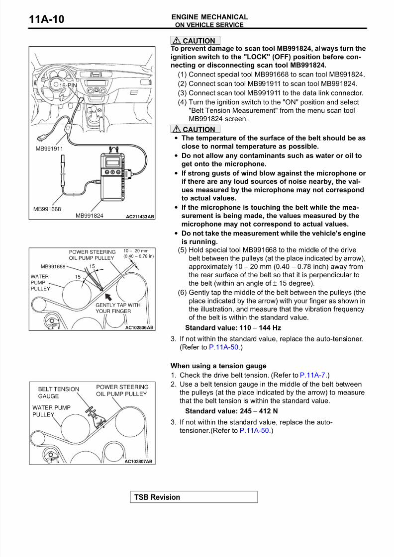
When using a tension gauge
1. Check the drive belt tension. (Refer to P.11A-7.)
2. Use a belt tension gauge in the middle of the belt between
the pulleys (at the place indicated by the arrow) to measurethat the belt tension is within the standard value.
Standard value: 245 − 412 N
3. If not within the standard value, replace the auto-
tensioner.(Refer to P.11A-50.)
AC211433
16-PIN
ABMB991824MB991668
MB991911
AC102806AB
MB991668
15˚
15˚
GENTLY TAP WITH
YOUR FINGER
WATERPUMP
PULLEY
POWER STEERING
OIL PUMP PULLEY
10 – 20 mm
(0.40 – 0.78 in)
AC102807AB
BELT TENSIONGAUGE
WATER PUMP
PULLEY
POWER STEERING
OIL PUMP PULLEY
8/8/2019 GR00003800-11A
http://slidepdf.com/reader/full/gr00003800-11a 11/66
ON VEHICLE SERVICE
TSB Revision
ENGINE MECHANICAL 11A-11
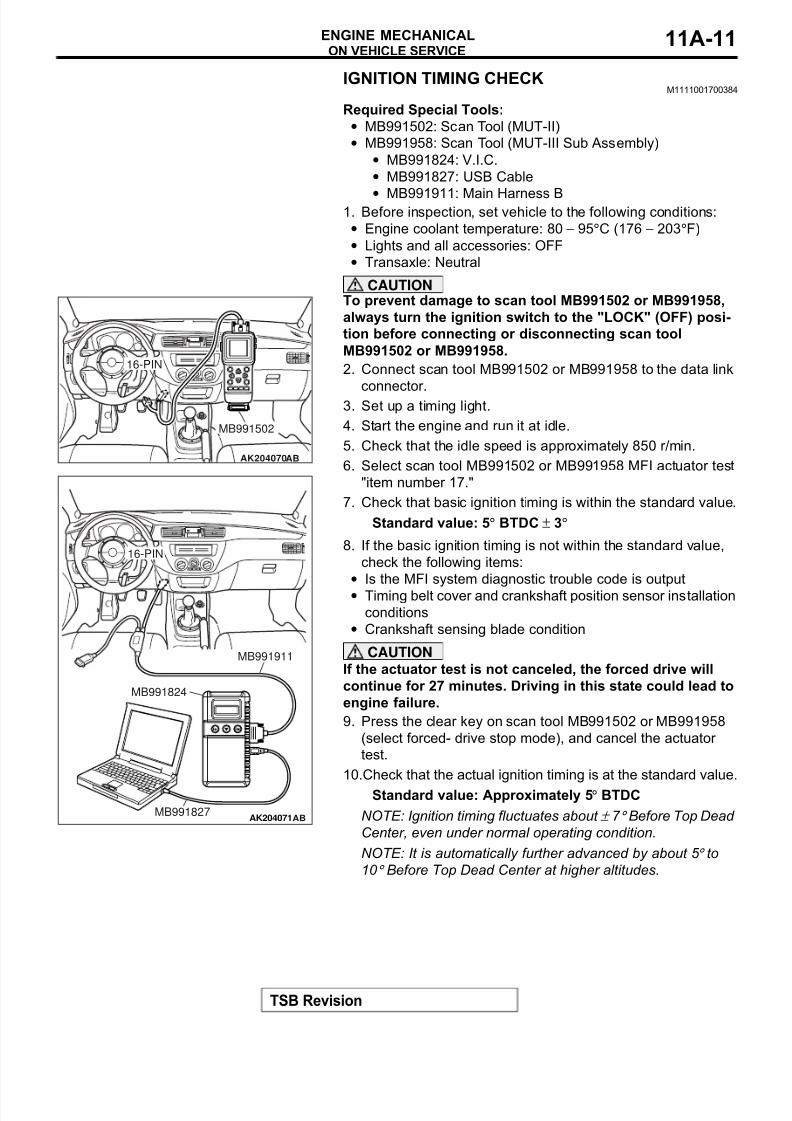
IGNITION TIMING CHECKM1111001700384
Required Special Tools:
• MB991502: Scan Tool (MUT-II)
• MB991958: Scan Tool (MUT-III Sub Assembly)
• MB991824: V.I.C.
• MB991827: USB Cable
• MB991911: Main Harness B1. Before inspection, set vehicle to the following conditions:
• Engine coolant temperature: 80 − 95°C (176 − 203°F)
• Lights and all accessories: OFF
• Transaxle: Neutral
CAUTIONTo prevent damage to scan tool MB991502 or MB991958,
always turn the ignition switch to the "LOCK" (OFF) posi-
tion before connecting or disconnecting scan tool
MB991502 or MB991958.
2. Connect scan tool MB991502 or MB991958 to the data link
connector.3. Set up a timing light.
4. Start the engine and run it at idle.
5. Check that the idle speed is approximately 850 r/min.
6. Select scan tool MB991502 or MB991958 MFI actuator test
"item number 17."
7. Check that basic ignition timing is within the standard value.
Standard value: 5° BTDC ± 3°
8. If the basic ignition timing is not within the standard value,
check the following items:
• Is the MFI system diagnostic trouble code is output
• Timing belt cover and crankshaft position sensor installation
conditions
• Crankshaft sensing blade condition
CAUTION
If the actuator test is not canceled, the forced drive will
continue for 27 minutes. Driving in this state could lead to
engine failure.
9. Press the clear key on scan tool MB991502 or MB991958
(select forced- drive stop mode), and cancel the actuator
test.
10.Check that the actual ignition timing is at the standard value.
Standard value: Approximately 5° BTDC
NOTE: Ignition timing fluctuates about ± 7 ° Before Top Dead
Center, even under normal operating condition.
NOTE: It is automatically further advanced by about 5 ° to
10 ° Before Top Dead Center at higher altitudes.
AK204070AB
MB991502
16-PIN
AK204071AB
MB991911
16-PIN
MB991827
MB991824
8/8/2019 GR00003800-11A
http://slidepdf.com/reader/full/gr00003800-11a 12/66
ON VEHICLE SERVICE
TSB Revision
ENGINE MECHANICAL11A-12
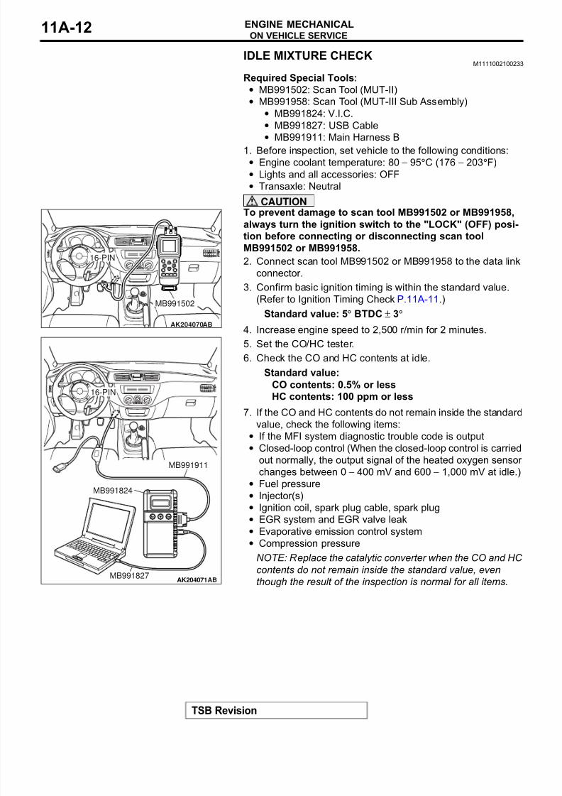
IDLE MIXTURE CHECKM1111002100233
Required Special Tools:
• MB991502: Scan Tool (MUT-II)
• MB991958: Scan Tool (MUT-III Sub Assembly)
• MB991824: V.I.C.
• MB991827: USB Cable
• MB991911: Main Harness B1. Before inspection, set vehicle to the following conditions:
• Engine coolant temperature: 80 − 95°C (176 − 203°F)
• Lights and all accessories: OFF
• Transaxle: Neutral
CAUTIONTo prevent damage to scan tool MB991502 or MB991958,
always turn the ignition switch to the "LOCK" (OFF) posi-
tion before connecting or disconnecting scan tool
MB991502 or MB991958.
2. Connect scan tool MB991502 or MB991958 to the data link
connector.
3. Confirm basic ignition timing is within the standard value.
(Refer to Ignition Timing Check P.11A-11.)
Standard value: 5° BTDC ± 3°
4. Increase engine speed to 2,500 r/min for 2 minutes.
5. Set the CO/HC tester.
6. Check the CO and HC contents at idle.
Standard value:
CO contents: 0.5% or less
HC contents: 100 ppm or less
7. If the CO and HC contents do not remain inside the standard
value, check the following items:
• If the MFI system diagnostic trouble code is output
• Closed-loop control (When the closed-loop control is carried
out normally, the output signal of the heated oxygen sensor
changes between 0 − 400 mV and 600 − 1,000 mV at idle.)
• Fuel pressure
• Injector(s)
• Ignition coil, spark plug cable, spark plug
• EGR system and EGR valve leak
• Evaporative emission control system
• Compression pressure
NOTE: Replace the catalytic converter when the CO and HC contents do not remain inside the standard value, even
though the result of the inspection is normal for all items.
AK204070AB
MB991502
16-PIN
AK204071AB
MB991911
16-PIN
MB991827
MB991824
8/8/2019 GR00003800-11A
http://slidepdf.com/reader/full/gr00003800-11a 13/66
ON VEHICLE SERVICE
TSB Revision
ENGINE MECHANICAL 11A-13
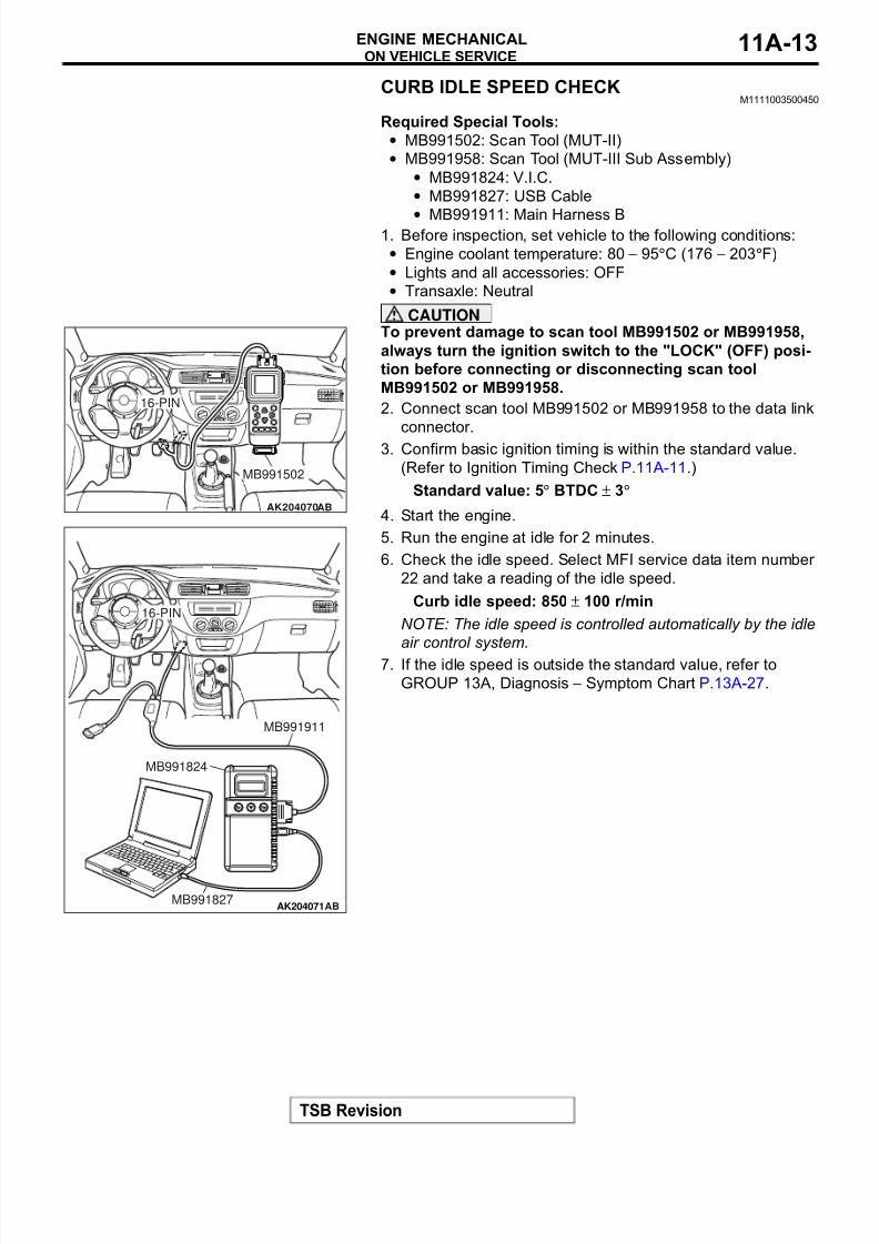
CURB IDLE SPEED CHECKM1111003500450
Required Special Tools:
• MB991502: Scan Tool (MUT-II)
• MB991958: Scan Tool (MUT-III Sub Assembly)
• MB991824: V.I.C.
• MB991827: USB Cable
• MB991911: Main Harness B1. Before inspection, set vehicle to the following conditions:
• Engine coolant temperature: 80 − 95°C (176 − 203°F)
• Lights and all accessories: OFF
• Transaxle: Neutral
CAUTIONTo prevent damage to scan tool MB991502 or MB991958,
always turn the ignition switch to the "LOCK" (OFF) posi-
tion before connecting or disconnecting scan tool
MB991502 or MB991958.
2. Connect scan tool MB991502 or MB991958 to the data link
connector.
3. Confirm basic ignition timing is within the standard value.
(Refer to Ignition Timing Check P.11A-11.)
Standard value: 5° BTDC ± 3°
4. Start the engine.
5. Run the engine at idle for 2 minutes.
6. Check the idle speed. Select MFI service data item number
22 and take a reading of the idle speed.
Curb idle speed: 850 ± 100 r/min
NOTE: The idle speed is controlled automatically by the idle
air control system.
7. If the idle speed is outside the standard value, refer to
GROUP 13A, Diagnosis − Symptom Chart P.13A-27.
AK204070AB
MB991502
16-PIN
AK204071AB
MB991911
16-PIN
MB991827
MB991824
8/8/2019 GR00003800-11A
http://slidepdf.com/reader/full/gr00003800-11a 14/66
ON VEHICLE SERVICE
TSB Revision
ENGINE MECHANICAL11A-14
COMPRESSION PRESSURE CHECKM1111002600421
1. Before inspection, check that the engine oil, starter and
battery are normal. Also, set the vehicle to the following
conditions:
• Engine coolant temperature: 80 − 95°C (176 − 203°F)
• Lights, and all accessories: OFF
• Transaxle: Neutral
2. Disconnect the spark plug cables.
3. Remove all of the spark plugs.
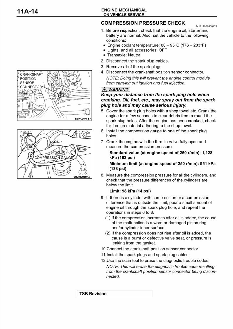
4. Disconnect the crankshaft position sensor connector.
NOTE: Doing this will prevent the engine control module
from carrying out ignition and fuel injection.
WARNING
Keep your distance from the spark plug hole whencranking. Oil, fuel, etc., may spray out from the spark
plug hole and may cause serious injury.
5. Cover the spark plug holes with a shop towel etc. Crank the
engine for a few seconds to clear debris from a round thespark plug holes. After the engine has been cranked, check
for foreign material adhering to the shop towel.
6. Install the compression gauge to one of the spark plug
holes.
7. Crank the engine with the throttle valve fully open and
measure the compression pressure.
Standard value (at engine speed of 250 r/min): 1,128
kPa (163 psi)
Minimum limit (at engine speed of 250 r/min): 951 kPa
(138 psi)
8. Measure the compression pressure for all the cylinders, and
check that the pressure differences of the cylinders are
below the limit.
Limit: 98 kPa (14 psi)
9. If there is a cylinder with compression or a compression
difference that is outside the limit, pour a small amount of
engine oil through the spark plug hole, and repeat the
operations in steps 6 to 8.
(1) If the compression increases after oil is added, the cause
of the malfunction is a worn or damaged piston ring
and/or cylinder inner surface.
(2) If the compression does not rise after oil is added, the
cause is a burnt or defective valve seat, or pressure is
leaking from the gasket.
10.Connect the crankshaft position sensor connector.
11.Install the spark plugs and spark plug cables.
12.Use the scan tool to erase the diagnostic trouble codes.
NOTE: This will erase the diagnostic trouble code resulting
from the crankshaft position sensor connector being discon-
nected.
AK204072
CRANKSHAFT
POSITION
SENSOR
CONNECTOR
AB
AK100050ABAK100050
COMPRESSION GAUGE
8/8/2019 GR00003800-11A
http://slidepdf.com/reader/full/gr00003800-11a 15/66
ON VEHICLE SERVICE
TSB Revision
ENGINE MECHANICAL 11A-15
NOTE: If the negative ( − ) cable has been disconnected from
the battery terminal in order to erase the diagnostic trouble
code, operate the engine at idle for approximately 10 min-
utes after restarting.
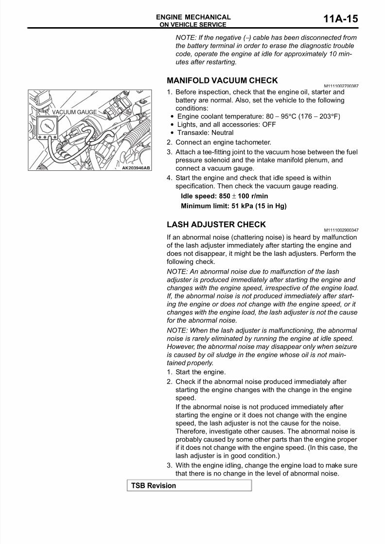
MANIFOLD VACUUM CHECKM1111002700387
1. Before inspection, check that the engine oil, starter andbattery are normal. Also, set the vehicle to the following
conditions:
• Engine coolant temperature: 80 − 95°C (176 − 203°F)
• Lights, and all accessories: OFF
• Transaxle: Neutral
2. Connect an engine tachometer.
3. Attach a tee-fitting joint to the vacuum hose between the fuel
pressure solenoid and the intake manifold plenum, and
connect a vacuum gauge.
4. Start the engine and check that idle speed is within
specification. Then check the vacuum gauge reading.
Idle speed: 850 ± 100 r/min
Minimum limit: 51 kPa (15 in Hg)
LASH ADJUSTER CHECKM1111002900347
If an abnormal noise (chattering noise) is heard by malfunction
of the lash adjuster immediately after starting the engine and
does not disappear, it might be the lash adjusters. Perform the
following check.
NOTE: An abnormal noise due to malfunction of the lash
adjuster is produced immediately after starting the engine and
changes with the engine speed, irrespective of the engine load.If, the abnormal noise is not produced immediately after start-
ing the engine or does not change with the engine speed, or it
changes with the engine load, the lash adjuster is not the cause
for the abnormal noise.
NOTE: When the lash adjuster is malfunctioning, the abnormal
noise is rarely eliminated by running the engine at idle speed.
However, the abnormal noise may disappear only when seizure
is caused by oil sludge in the engine whose oil is not main-
tained properly.
1. Start the engine.
2. Check if the abnormal noise produced immediately after starting the engine changes with the change in the engine
speed.
If the abnormal noise is not produced immediately after
starting the engine or it does not change with the engine
speed, the lash adjuster is not the cause for the noise.
Therefore, investigate other causes. The abnormal noise is
probably caused by some other parts than the engine proper
if it does not change with the engine speed. (In this case, the
lash adjuster is in good condition.)
3. With the engine idling, change the engine load to make sure
that there is no change in the level of abnormal noise.
AK203946AB
VACUUM GAUGE
8/8/2019 GR00003800-11A
http://slidepdf.com/reader/full/gr00003800-11a 16/66
ON VEHICLE SERVICE
TSB Revision
ENGINE MECHANICAL11A-16
If there is a change in the level of abnormal noise, suspect a
tapping noise due to worn crankshaft bearing or connecting
rod bearing. (In this case, the lash adjuster is in good
condition.)
4. After completion of warm-up, run the engine at idle to check
for abnormal noise.
If the noise is reduced or disappears, clean the lash adjuster
(Refer to GROUP 11B − Engine overhaul − Rocker Arms
and Camshaft − Inspection P.11B-32.) It is suspected that
the noise is due to collapse of the lash adjuster. If there is no
change in the level of the abnormal noise, proceed to step 5.
5. Run the engine to bleed the lash adjuster system. (Refer to.)
6. If the abnormal noise does not disappear after air bleeding
operation, clean the lash adjuster (Refer to GROUP 11B −
Engine overhaul − Rocker Arms and Camshaft − Inspection
P.11B-32.).
Bleeding lash adjuster system
NOTE: Parking the vehicle on a grade for a long time may drainoil from the lash adjuster, causing air to enter the high pressure
chamber when starting the engine.
NOTE: After parking for many hours, oil may drain from the oil
passage and take time before oil is supplied to the lash
adjuster, causing air to enter the high pressure chamber.
NOTE: In the above cases, abnormal noise can be eliminated
by bleeding the lash adjuster system.
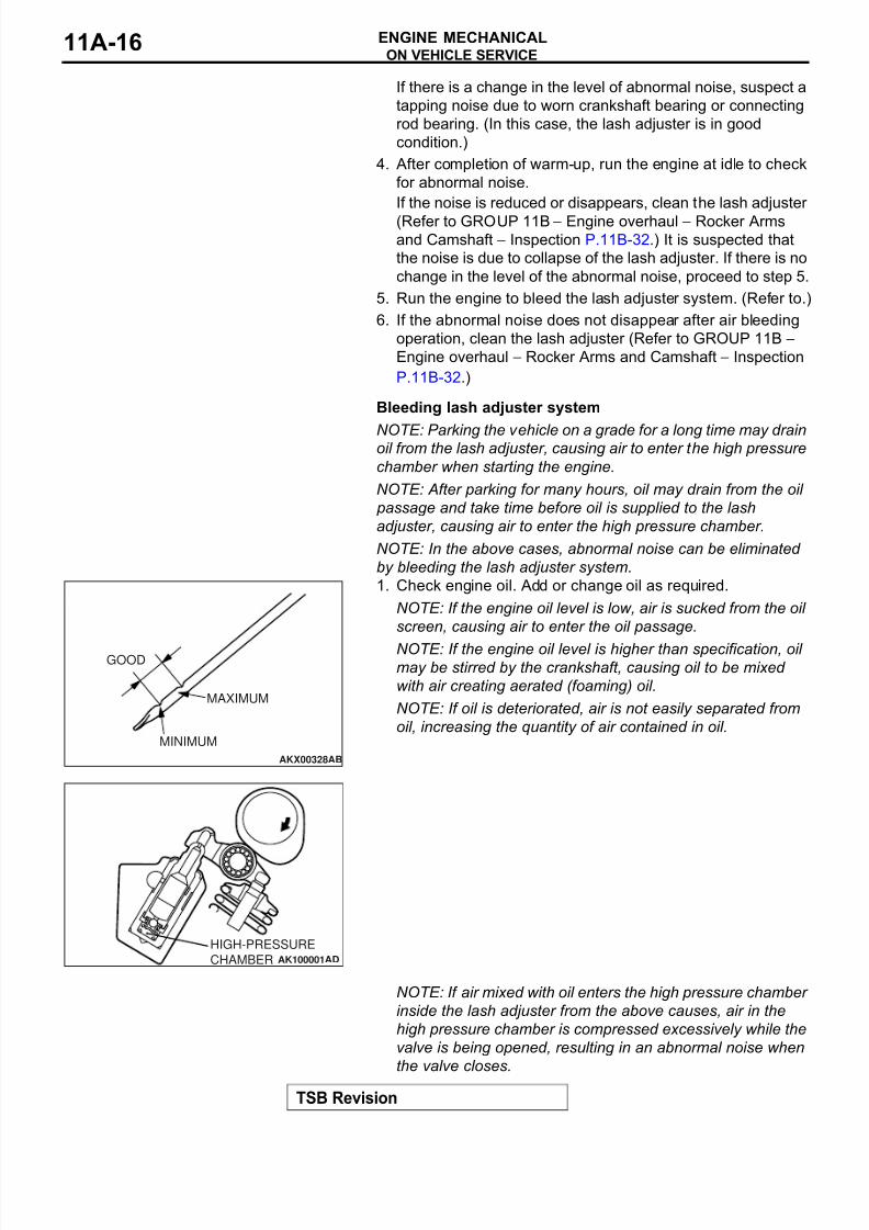
1. Check engine oil. Add or change oil as required.
NOTE: If the engine oil level is low, air is sucked from the oil
screen, causing air to enter the oil passage.
NOTE: If the engine oil level is higher than specification, oil may be stirred by the crankshaft, causing oil to be mixed
with air creating aerated (foaming) oil.
NOTE: If oil is deteriorated, air is not easily separated from
oil, increasing the quantity of air contained in oil.
NOTE: If air mixed with oil enters the high pressure chamber
inside the lash adjuster from the above causes, air in the
high pressure chamber is compressed excessively while the
valve is being opened, resulting in an abnormal noise when
the valve closes.
AKX00328
GOOD
MINIMUM
MAXIMUM
AB
AK100001
HIGH-PRESSURE
CHAMBER AD
8/8/2019 GR00003800-11A
http://slidepdf.com/reader/full/gr00003800-11a 17/66
ON VEHICLE SERVICE
TSB Revision
ENGINE MECHANICAL 11A-17
This is the same phenomenon as that observed when the
valve clearance has become excessive. The lash adjuster
can resume normal function when air entered the lash
adjuster is removed.
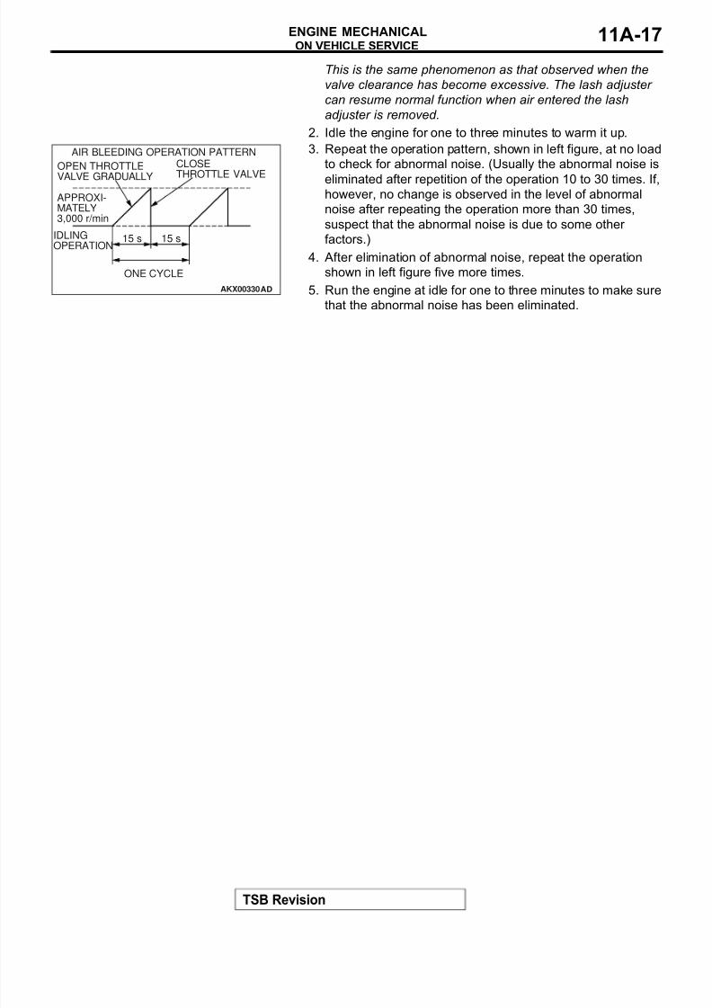
2. Idle the engine for one to three minutes to warm it up.
3. Repeat the operation pattern, shown in left figure, at no load
to check for abnormal noise. (Usually the abnormal noise is
eliminated after repetition of the operation 10 to 30 times. If,however, no change is observed in the level of abnormal
noise after repeating the operation more than 30 times,
suspect that the abnormal noise is due to some other
factors.)
4. After elimination of abnormal noise, repeat the operation
shown in left figure five more times.
5. Run the engine at idle for one to three minutes to make sure
that the abnormal noise has been eliminated.
AKX00330
OPEN THROTTLE
VALVE GRADUALLY
CLOSE
THROTTLE VALVE
APPROXI-MATELY3,000 r/min
IDLINGOPERATION
ONE CYCLE
15 s 15 s
AIR BLEEDING OPERATION PATTERN
AD
8/8/2019 GR00003800-11A
http://slidepdf.com/reader/full/gr00003800-11a 18/66
ENGINE ASSEMBLY
TSB Revision
ENGINE MECHANICAL11A-18
ENGINE ASSEMBLY
REMOVAL AND INSTALLATIONM1112001000667
CAUTION
• If the vehicle is equipped with the Bremboä disc brake, during maintenance, take care not to con-
tact the parts or tools to the caliper because the paint of caliper will be scratched.
• *: indicates parts which should be temporarily tightened, and then fully tightened with the engineweight applied on the vehicle body.
Pre-removal Operation
• Fuel Line Pressure Reduction [Refer to GROUP 13A, On-vehicle Service − Fuel Pump Connector Disconnection(How to Reduce Pressurized Fuel Lines) P.13A-765.]
• Hood Removal (Refer to GROUP 42, Hood P.42-7.)
• Under Cover Removal (Refer to GROUP 51, FrontBumper P.51-2.)
• Side Cover Removal
• Engine Oil Draining (Refer to GROUP 12, On-vehicle Ser-vice − Engine Oil Replacement P.12-3.)
• Engine Coolant Draining (Refer to GROUP 14, On-vehicle
Service − Engine Coolant Replacement P.14-18.)• Strut Tower Bar Removal (Refer to GROUP 42, Strut
Tower Bar.)
• Air Cleaner Assembly Removal (Refer to GROUP 15, Air Cleaner P.15-7.)
• Air Pipe C, Air Pipe B and Air Hose A Removal (Refer toGROUP 15, Charge Air Cooler P.15-8.)
• Battery and Battery Tray Removal
• Accelerator Cable Removal (Refer to GROUP 17, Accel-erator Cable and Pedal P.17-5.)
• Rocker Cover Center Cover Removal (Refer to P.11A-28.)
• Radiator Assembly Removal (Refer to GROUP 14, Radia-tor P.14-22.)
• Front Axle Crossmember Bar Removal (Refer to GROUP
32, Engine Roll Stopper and Centermember P.32-6.)• Front Exhaust Pipe Removal (Refer to GROUP 15,
Exhaust Pipe and Main Muffler P.15-23.)
• Air Outlet Fitting Removal (Refer to GROUP 15, ExhaustManifold and Turbocharger P.15-16.)
Post-installation Operation
• Air Outlet Fitting Installation (Refer to GROUP 15,Exhaust Manifold and Turbocharger P.15-16.)
• Front Exhaust Pipe Installation (Refer to GROUP 15,Exhaust Pipe and Main Muffler P.15-23.)
• Front Axle Crossmember Bar Installation (Refer toGROUP 32, Engine Roll Stopper and Centermember P.32-6.)
• Radiator Assembly Installation (Refer to GROUP 14,Radiator P.14-22.)
• Rocker Cover Center Cover Installation (Refer to P.11A-
28.)• Accelerator Cable Installation (Refer to GROUP 17,Accelerator Cable and Pedal P.17-5.)
• Battery and Battery Tray Installation
• Air Pipe C, Air Pipe B and Air Hose A Installation (Refer toGROUP 15, Charge Air Cooler P.15-8.)
• Air Cleaner Assembly Installation (Refer to GROUP 15,Air Cleaner P.15-7.)
• Strut Tower Bar Installation (Refer to GROUP 42, StrutTower Bar.)
• Engine Coolant Refilling (Refer to GROUP 14, On-vehicleService − Engine Coolant Replacement P.14-18.)
• Engine Oil Refilling (Refer to GROUP 12, On-vehicle Ser-vice − Engine Oil Replacement P.12-3.)
• Drive Belt Tension Check (Refer to P.11A-7.)
• Side Cover Installation• Under Cover Installation (Refer to GROUP 51, Front
Bumper P.51-2.)
• Accelerator Cable Adjustment (Refer to GROUP 17, On-vehicle Service − Accelerator Cable Check and Adjust-ment P.17-4.)
• Hood Installation (Refer to GROUP 42, Hood P.42-7.)
• Fuel Leak Check
8/8/2019 GR00003800-11A
http://slidepdf.com/reader/full/gr00003800-11a 19/66
ENGINE ASSEMBLY
TSB Revision
ENGINE MECHANICAL 11A-19
AC211077
5.0 ± 1.0 N·m
44 ± 9 in-lb
26 ± 5 N·m
19 ± 4 ft-lb
1
1
19
18
17
16
15
1413
12
10
9
8
7
6
5
11
4
32
2021
AB
11 ± 1 N·m98 ± 8 in-lb
14 ± 3 N·m
124 ± 26 in-lb 5.0 ± 1.0 N·m
44 ± 9 in-lb
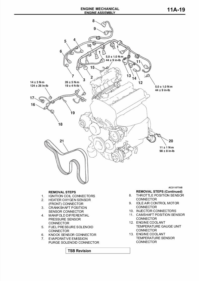
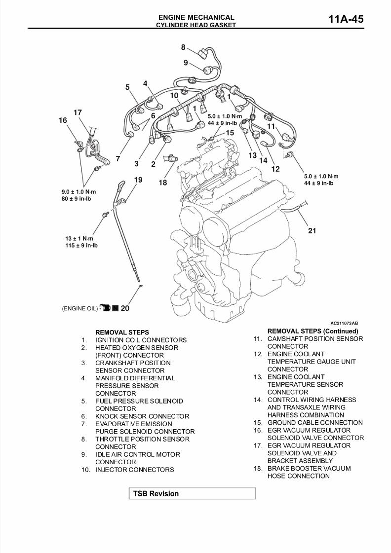
REMOVAL STEPS
1. IGNITION COIL CONNECTORS2. HEATER OXYGEN SENSOR
(FRONT) CONNECTOR
3. CRANKSHAFT POSITION
SENSOR CONNECTOR
4. MANIFOLD DIFFERENTIAL
PRESSURE SENSOR
CONNECTOR
5. FUEL PRESSURE SOLENOID
CONNECTOR
6. KNOCK SENSOR CONNECTOR
7. EVAPORATIVE EMISSION
PURGE SOLENOID CONNECTOR
8. THROTTLE POSITION SENSORCONNECTOR
9. IDLE AIR CONTROL MOTOR
CONNECTOR
10. INJECTOR CONNECTORS
11. CAMSHAFT POSITION SENSOR
CONNECTOR
12. ENGINE COOLANT
TEMPERATURE GAUGE UNIT
CONNECTOR
13. ENGINE COOLANT
TEMPERATURE SENSOR
CONNECTOR
REMOVAL STEPS (Continued)

8/8/2019 GR00003800-11A
http://slidepdf.com/reader/full/gr00003800-11a 20/66
ENGINE ASSEMBLY
TSB Revision
ENGINE MECHANICAL11A-20
14. CONTROL WIRING HARNESS
AND TRANSAXLE WIRING
HARNESS COMBINATION
15. GROUND CABLE CONNECTION
16. GENERATOR CONNECTOR
17. GENERATOR TERMINAL
18. EGR VACUUM REGULATOR
SOLENOID VALVE CONNECTOR
19. ENGINE OIL PRESSURE SWITCH
CONNECTOR
20. TURBOCHARGER WASTEGATE
ACTUATOR BOLTS<<A>> 21. DRIVE BELT
REMOVAL STEPS (Continued)
AC211078AB
12 ± 2 N·m
102 ± 22 in-lb
22 ± 4 N·m
16 ± 3 ft-lb
40 ± 5 N·m
30 ± 3 ft-lb
22 ± 4 N·m
16 ± 3 ft-lb
32N
98 ± 10 N·m*
73 ± 7 ft-lb*
30 N
67 ± 7 N·m*
50 ± 5 ft-lb*
42 ± 2 N·m
31 ± 1 ft-lb
42 ± 2 N·m
31 ± 1 ft-lb
36 N (ENGINE OIL)
5.0 ± 1.0 N·m
44 ± 9 in-lb
29
2827
26
25
24
23
22
38
37
35
34
33
31
REMOVAL STEPS
22. BRAKE BOOSTER VACUUM
HOSE CONNECTION
23. PURGE HOSE CONNECTION
24. POWER STEERING PRESSURE
SWITCH CONNECTOR
25. POWER STEERING OIL PUMP
HEAT PROTECTOR
REMOVAL STEPS (Continued)
8/8/2019 GR00003800-11A
http://slidepdf.com/reader/full/gr00003800-11a 21/66
ENGINE ASSEMBLY
TSB Revision
ENGINE MECHANICAL 11A-21
Required Special Tools:
• MB991453: Engine Hanger Assembly• MB991454: Engine Hanger Balancer
• MB991895: Engine Hanger
• MB991928: Engine Hanger • MZ203827: Engine Lifter
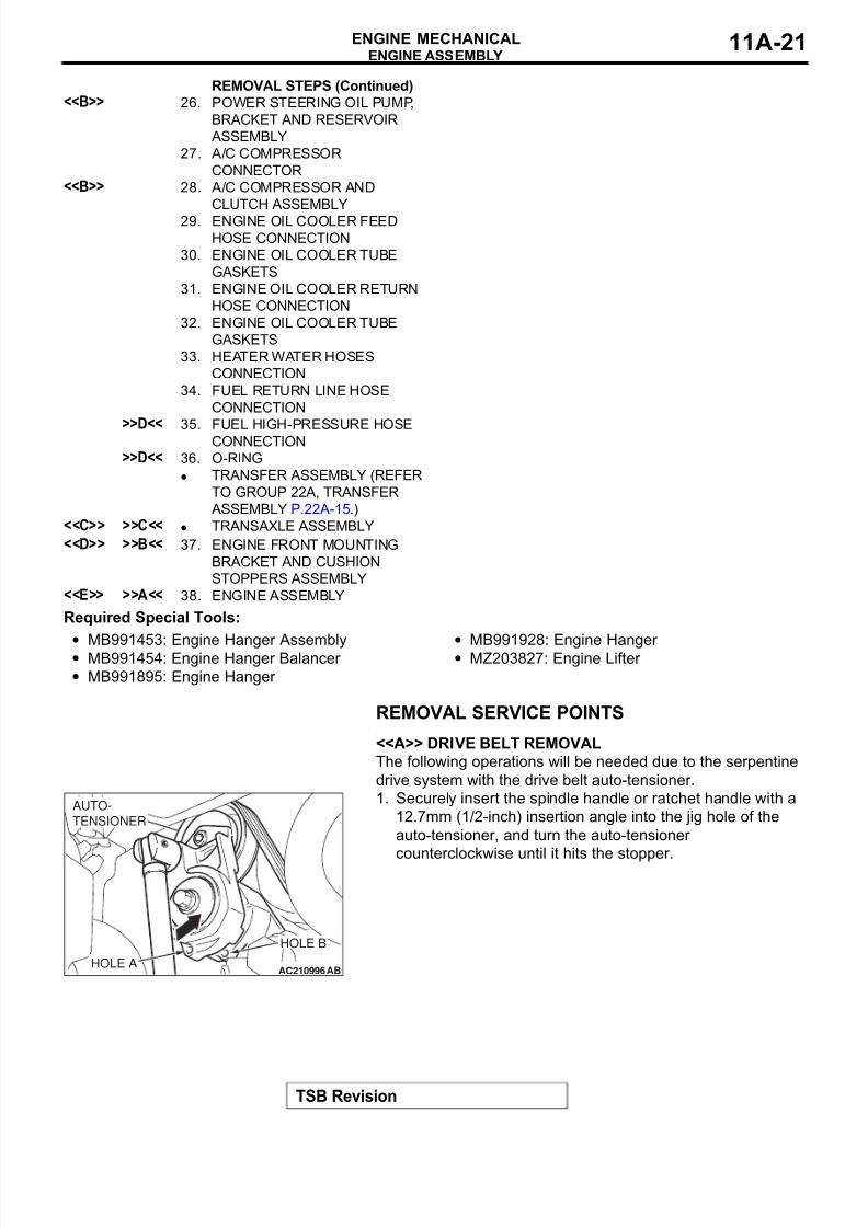
REMOVAL SERVICE POINTS.
<<A>> DRIVE BELT REMOVAL
The following operations will be needed due to the serpentine
drive system with the drive belt auto-tensioner.
1. Securely insert the spindle handle or ratchet handle with a
12.7mm (1/2-inch) insertion angle into the jig hole of the
auto-tensioner, and turn the auto-tensioner
counterclockwise until it hits the stopper.
<<B>> 26. POWER STEERING OIL PUMP,
BRACKET AND RESERVOIR
ASSEMBLY
27. A/C COMPRESSOR
CONNECTOR<<B>> 28. A/C COMPRESSOR AND
CLUTCH ASSEMBLY
29. ENGINE OIL COOLER FEED
HOSE CONNECTION
30. ENGINE OIL COOLER TUBE
GASKETS
31. ENGINE OIL COOLER RETURN
HOSE CONNECTION
32. ENGINE OIL COOLER TUBE
GASKETS
33. HEATER WATER HOSES
CONNECTION
34. FUEL RETURN LINE HOSE
CONNECTION>>D<<
35. FUEL HIGH-PRESSURE HOSECONNECTION>>D<< 36. O-RING
• TRANSFER ASSEMBLY (REFER
TO GROUP 22A, TRANSFER
ASSEMBLY P.22A-15.)<<C>> >>C<< • TRANSAXLE ASSEMBLY
<<D>> >>B<< 37. ENGINE FRONT MOUNTING
BRACKET AND CUSHION
STOPPERS ASSEMBLY<<E>> >>A<< 38. ENGINE ASSEMBLY
REMOVAL STEPS (Continued)
AC210996AB
AUTO-
TENSIONER
HOLE A
HOLE B
8/8/2019 GR00003800-11A
http://slidepdf.com/reader/full/gr00003800-11a 22/66
ENGINE ASSEMBLY
TSB Revision
ENGINE MECHANICAL11A-22
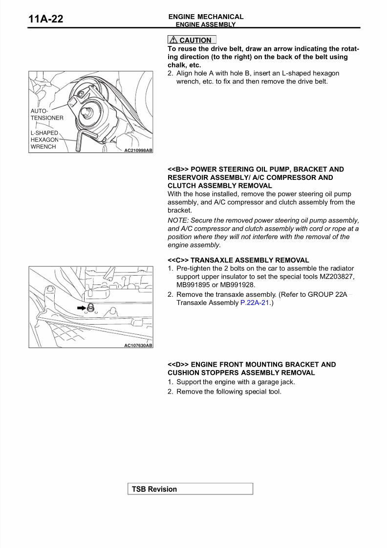
CAUTION
To reuse the drive belt, draw an arrow indicating the rotat-
ing direction (to the right) on the back of the belt using
chalk, etc.
2. Align hole A with hole B, insert an L-shaped hexagon
wrench, etc. to fix and then remove the drive belt.
.
<<B>> POWER STEERING OIL PUMP, BRACKET AND
RESERVOIR ASSEMBLY/ A/C COMPRESSOR AND
CLUTCH ASSEMBLY REMOVAL
With the hose installed, remove the power steering oil pumpassembly, and A/C compressor and clutch assembly from the
bracket.
NOTE: Secure the removed power steering oil pump assembly,
and A/C compressor and clutch assembly with cord or rope at a
position where they will not interfere with the removal of the
engine assembly..
<<C>> TRANSAXLE ASSEMBLY REMOVAL
1. Pre-tighten the 2 bolts on the car to assemble the radiator
support upper insulator to set the special tools MZ203827,
MB991895 or MB991928.2. Remove the transaxle assembly. (Refer to GROUP 22A −
Transaxle Assembly P.22A-21.)
.
<<D>> ENGINE FRONT MOUNTING BRACKET AND
CUSHION STOPPERS ASSEMBLY REMOVAL
1. Support the engine with a garage jack.2. Remove the following special tool.
AC210998AB
L-SHAPED
HEXAGON
WRENCH
AUTO-
TENSIONER
AC107630AB
8/8/2019 GR00003800-11A
http://slidepdf.com/reader/full/gr00003800-11a 23/66
ENGINE ASSEMBLY
TSB Revision
ENGINE MECHANICAL 11A-23
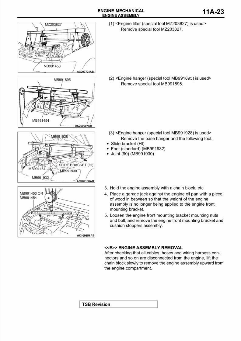
(1) <Engine lifter (special tool MZ203827) is used>
Remove special tool MZ203827.
(2) <Engine hanger (special tool MB991895) is used>
Remove special tool MB991895.
(3) <Engine hanger (special tool MB991928) is used>
Remove the base hanger and the following tool.
• Slide bracket (HI)
• Foot (standard) (MB991932)
• Joint (90) (MB991930)
3. Hold the engine assembly with a chain block, etc.
4. Place a garage jack against the engine oil pan with a piece
of wood in between so that the weight of the engine
assembly is no longer being applied to the engine front
mounting bracket.
5. Loosen the engine front mounting bracket mounting nuts
and bolt, and remove the engine front mounting bracket and
cushion stoppers assembly.
.
<<E>> ENGINE ASSEMBLY REMOVAL
After checking that all cables, hoses and wiring harness con-
nectors and so on are disconnected from the engine, lift the
chain block slowly to remove the engine assembly upward from
the engine compartment.
AC207721
MB991453
MZ203827
AB
AC209097
MB991895
MB991454
AB
AC209108AB
MB991928
SLIDE BRACKET (HI)MB991454
MB991930
MB991932
AC100954AE
MB991453 OR
MB991454
AC100954

8/8/2019 GR00003800-11A
http://slidepdf.com/reader/full/gr00003800-11a 24/66
ENGINE ASSEMBLY
TSB Revision
ENGINE MECHANICAL11A-24
INSTALLATION SERVICE POINTS.
>>A<< ENGINE ASSEMBLY INSTALLATION
Install the engine assembly, being careful not to pinch the
cables, hoses or wiring harness connectors.
.
>>B<< ENGINE FRONT MOUNTING BRACKET AND
CUSHION STOPPERS ASSEMBLY INSTALLATION
1. Arrow marks on the engine front mounting cushion stopper
should face the shown direction.
NOTE: Disregard F and R stamped as a shared part.2. Place a garage jack against the engine oil pan with a piece
of wood in between, and install the engine front mounting
bracket and cushion stoppers while adjusting the position of
the engine.
3. Support the engine assembly with a garage jack.
4. Remove the chain block.
5. Use the following special tool as during removal to support
the engine.
(1) <Engine lifter (special tool MZ203827) is used>
Set special tool MZ203827.
(2) <Engine hanger (special tool MB991895) is used>
Set special tool MB991895.
AC100954AE
MB991453 OR
MB991454
AC100954
R
F
F
R
AC210426
ENGINE SIDE ENGINE SIDE
<VEHICLE
REAR VIEW>
<VEHICLE
FRONT VIEW>
ENGINE FRONT MOUNTING
CUSHION STOPPER
AB
AC207721
MB991453
MZ203827
AB
AC209097
MB991895
MB991454
AB
8/8/2019 GR00003800-11A
http://slidepdf.com/reader/full/gr00003800-11a 25/66
ENGINE ASSEMBLY
TSB Revision
ENGINE MECHANICAL 11A-25
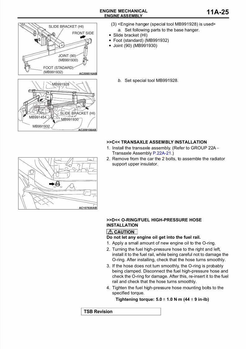
(3) <Engine hanger (special tool MB991928) is used>
a. Set following parts to the base hanger.
• Slide bracket (HI)
• Foot (standard) (MB991932)
• Joint (90) (MB991930)
b. Set special tool MB991928.
.
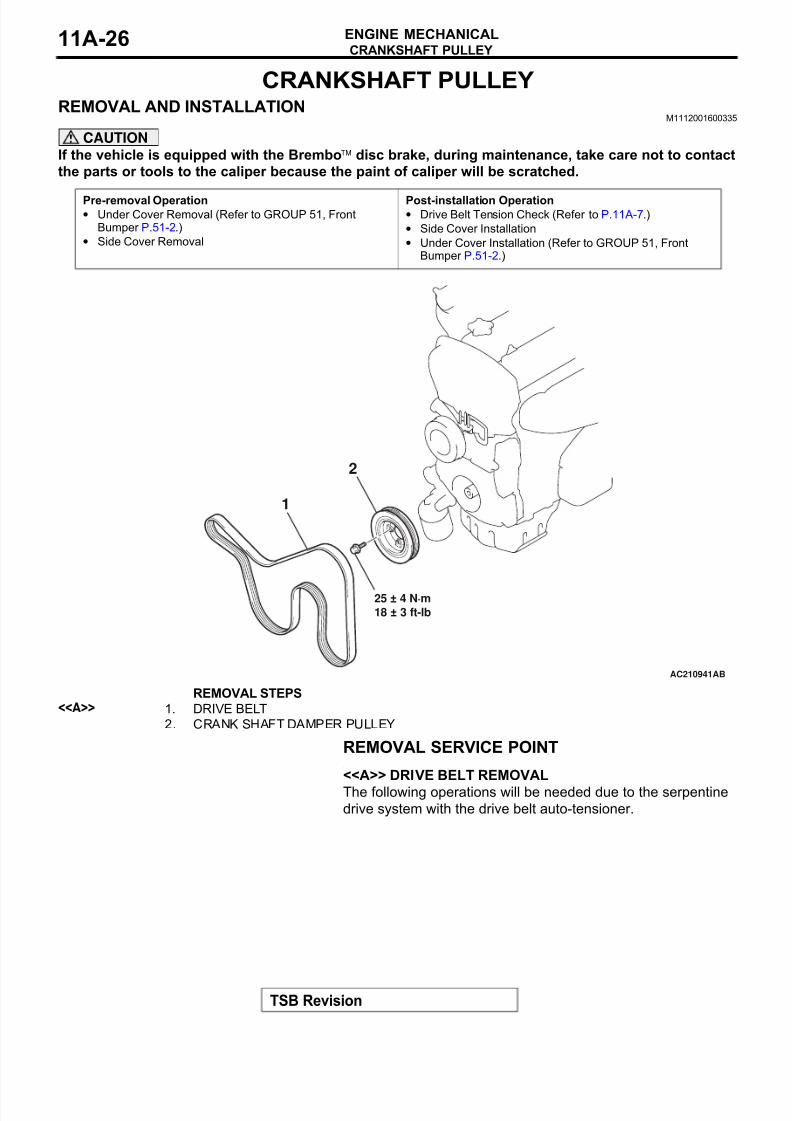
>>C<< TRANSAXLE ASSEMBLY INSTALLATION
1. Install the transaxle assembly. (Refer to GROUP 22A −
Transaxle Assembly P.22A-21.)
2. Remove from the car the 2 bolts, to assemble the radiator
support upper insulator.
.
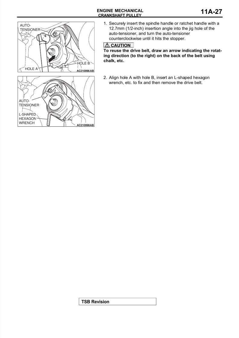
>>D<< O-RING/FUEL HIGH-PRESSURE HOSE
INSTALLATION
CAUTION
Do not let any engine oil get into the fuel rail.
1. Apply a small amount of new engine oil to the O-ring.2. Turning the fuel high-pressure hose to the right and left,
install it to the fuel rail, while being careful not to damage the
O-ring. After installing, check that the hose turns smoothly.
3. If the hose does not turn smoothly, the O-ring is probably
being clamped. Disconnect the fuel high-pressure hose and
check the O-ring for damage. After this, re-insert it to the fuel
rail and check that the hose turns smoothly.
4. Tighten the fuel high-pressure hose mounting bolts to the
specified torque.
Tightening torque: 5.0 ± 1.0 N⋅m (44 ± 9 in-lb)
AC209516AB
SLIDE BRACKET (HI)
JOINT (90)
(MB991930)
FOOT (STADARD)
(MB991932)
FRONT SIDE
AC209108AB
MB991928
SLIDE BRACKET (HI)MB991454
MB991930
MB991932
AC107630AB
8/8/2019 GR00003800-11A
http://slidepdf.com/reader/full/gr00003800-11a 26/66
CRANKSHAFT PULLEY
TSB Revision
ENGINE MECHANICAL11A-26
CRANKSHAFT PULLEY
REMOVAL AND INSTALLATIONM1112001600335
CAUTION
If the vehicle is equipped with the Bremboä disc brake, during maintenance, take care not to contact
the parts or tools to the caliper because the paint of caliper will be scratched.
REMOVAL SERVICE POINT.
<<A>> DRIVE BELT REMOVAL
The following operations will be needed due to the serpentine
drive system with the drive belt auto-tensioner.
Pre-removal Operation• Under Cover Removal (Refer to GROUP 51, Front
Bumper P.51-2.)
• Side Cover Removal
Post-installation Operation• Drive Belt Tension Check (Refer to P.11A-7.)
• Side Cover Installation
• Under Cover Installation (Refer to GROUP 51, FrontBumper P.51-2.)
AC210941AB
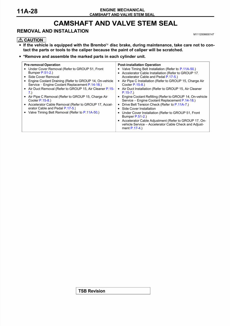
25 ± 4 N·m
18 ± 3 ft-lb
1
2
REMOVAL STEPS<<A>> 1. DRIVE BELT
2. CRANK SHAFT DAMPER PULLEY
8/8/2019 GR00003800-11A
http://slidepdf.com/reader/full/gr00003800-11a 27/66
CRANKSHAFT PULLEY
TSB Revision
ENGINE MECHANICAL 11A-27
1. Securely insert the spindle handle or ratchet handle with a
12.7mm (1/2-inch) insertion angle into the jig hole of the
auto-tensioner, and turn the auto-tensioner
counterclockwise until it hits the stopper.
CAUTION
To reuse the drive belt, draw an arrow indicating the rotat-
ing direction (to the right) on the back of the belt using
chalk, etc.
2. Align hole A with hole B, insert an L-shaped hexagon
wrench, etc. to fix and then remove the drive belt.
AC210996AB
AUTO-
TENSIONER
HOLE A
HOLE B
AC210998AB
L-SHAPED
HEXAGONWRENCH
AUTO-
TENSIONER
8/8/2019 GR00003800-11A
http://slidepdf.com/reader/full/gr00003800-11a 28/66
CAMSHAFT AND VALVE STEM SEAL
TSB Revision
ENGINE MECHANICAL11A-28
CAMSHAFT AND VALVE STEM SEAL
REMOVAL AND INSTALLATIONM1112006600147
CAUTION
• If the vehicle is equipped with the Bremboä disc brake, during maintenance, take care not to con-
tact the parts or tools to the caliper because the paint of caliper will be scratched.
• *Remove and assemble the marked parts in each cylinder unit.
Pre-removal Operation
• Under Cover Removal (Refer to GROUP 51, FrontBumper P.51-2.)
• Side Cover Removal
• Engine Coolant Draining (Refer to GROUP 14, On-vehicleService − Engine Coolant Replacement P.14-18.)
• Air Duct Removal (Refer to GROUP 15, Air Cleaner P.15-7.)
• Air Pipe C Removal (Refer to GROUP 15, Charge Air Cooler P.15-8.)
• Accelerator Cable Removal (Refer to GROUP 17, Accel-erator Cable and Pedal P.17-5.)
•Valve Timing Belt Removal (Refer to P.11A-50.)
Post-installation Operation
• Valve Timing Belt Installation (Refer to P.11A-50.)
• Accelerator Cable Installation (Refer to GROUP 17,Accelerator Cable and Pedal P.17-5.)
• Air Pipe C Installation (Refer to GROUP 15, Charge Air Cooler P.15-8.)
• Air Duct Installation (Refer to GROUP 15, Air Cleaner P.15-7.)
• Engine Coolant Refilling (Refer to GROUP 14, On-vehicleService − Engine Coolant Replacement P.14-18.)
• Drive Belt Tension Check (Refer to P.11A-7.)
• Side Cover Installation
• Under Cover Installation (Refer to GROUP 51, FrontBumper P.51-2.)
• Accelerator Cable Adjustment (Refer to GROUP 17, On-vehicle Service − Accelerator Cable Check and Adjust-ment P.17-4.)
8/8/2019 GR00003800-11A
http://slidepdf.com/reader/full/gr00003800-11a 29/66
CAMSHAFT AND VALVE STEM SEAL
TSB Revision
ENGINE MECHANICAL 11A-29
AC211071
1
16
15
14
13
12
10
9
8
7
6
5
11
4
3
2
N
N
3.0 ± 0.5 N·m
27 ± 4 in-lb
3.5 ± 0.5 N·m
31 ± 4 in-lb11 ± 1 N·m98 ± 8 in-lb
11 ± 1 N·m
98 ± 8 in-lb
11 ± 1 N·m
98 ± 8 in-lb
5.0 ± 1.0 N·m
44 ± 9 in-lb
11 ± 1 N·m
98 ± 8 in-lb
10.5 ± 0.5 N·m
93 ± 4 in-lb
AP
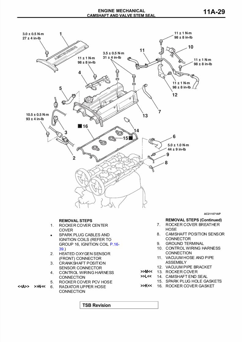
REMOVAL STEPS
1. ROCKER COVER CENTER
COVER
• SPARK PLUG CABLES AND
IGNITION COILS (REFER TOGROUP 16, IGNITION COIL P.16-
39.)
2. HEATED OXYGEN SENSOR
(FRONT) CONNECTOR
3. CRANKSHAFT POSITION
SENSOR CONNECTOR
4. CONTROL WIRING HARNESS
CONNECTION
5. ROCKER COVER PCV HOSE<<A>> >>N<< 6. RADIATOR UPPER HOSE
CONNECTION
7. ROCKER COVER BREATHER
HOSE
8. CAMSHAFT POSITION SENSOR
CONNECTOR9. GROUND TERMINAL
10. CONTROL WIRING HARNESS
CONNECTION
11. VACUUM HOSE AND PIPE
ASSEMBLY
12. VACUUM PIPE BRACKET>>M<< 13. ROCKER COVER>>L<< 14. CAMSHAFT END SEAL
15. SPARK PLUG HOLE GASKETS>>K<< 16. ROCKER COVER GASKET
REMOVAL STEPS (Continued)
8/8/2019 GR00003800-11A
http://slidepdf.com/reader/full/gr00003800-11a 30/66
CAMSHAFT AND VALVE STEM SEAL
TSB Revision
ENGINE MECHANICAL11A-30
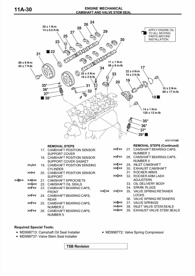
Required Special Tools:
• MD998713: Camshaft Oil Seal Installer
• MD998737: Valve Stem Seal Installer
• MD998772: Valve Spring Compressor
AC211072AZ
APPLY ENGINE OILTO ALL MOVINGPARTS BEFOREINSTALLATION.
14 ± 1 N·m
120 ± 13 in-lb
22 ± 4 N·m
16 ± 3 ft-lb
89 ± 9 N·m
65 ± 7 ft-lb
25 ± 4 N·m
18 ± 3 ft-lb
11 ± 1 N·m
98 ± 8 in-lb
20 ± 1 N·m
14 ± 0.5 ft-lb
10 ± 2 N·m
89 ± 17 in-lb
N
36*
38*
37*
35*
N
36*
39*
37*
35*
19
18
17
2928
27
26
25
24
23
22
20
21
34
33
32
30
31
N
N
AZ
REMOVAL STEPS17. CAMSHAFT POSITION SENSOR
SUPPORT COVER
18. CAMSHAFT POSITION SENSOR
SUPPORT COVER GASKET>>J<< 19. CAMSHAFT POSITION SENSING
CYLINDER>>I<< 20. CAMSHAFT POSITION SENSOR
SUPPORT<<B>> >>H<< 21. CAMSHAFT SPROCKETS
>>G<< 22. CAMSHAFT OIL SEALS>>F<< 23. CAMSHAFT BEARING CAPS,
FRONT>>F<< 24. CAMSHAFT BEARING CAPS,
REAR>>F<< 25. CAMSHAFT BEARING CAPS,
NUMBER 2>>F<< 26. CAMSHAFT BEARING CAPS,
NUMBER 5
>>F<< 27. CAMSHAFT BEARING CAPS,
NUMBER 3>>F<< 28. CAMSHAFT BEARING CAPS,
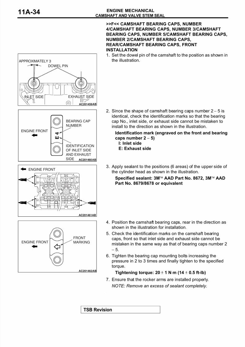
NUMBER 4>>E<< 29. INLET CAMSHAFT>>E<< 30. EXHAUST CAMSHAFT
31. ROCKER ARMS>>D<< 32. ROCKER ARM LASH
ADJUSTERS
33. OIL DELIVERY BODY
34. SPARK PLUGS<<C>> >>C<< 35. VALVE SPRING RETAINER
LOCKS
36. VALVE SPRING RETAINERS>>B<< 37. VALVE SPRINGS>>A<< 38. INLET VALVE STEM SEALS>>A<< 39. EXHAUST VALVE STEM SEALS
REMOVAL STEPS (Continued)
8/8/2019 GR00003800-11A
http://slidepdf.com/reader/full/gr00003800-11a 31/66
CAMSHAFT AND VALVE STEM SEAL
TSB Revision
ENGINE MECHANICAL 11A-31
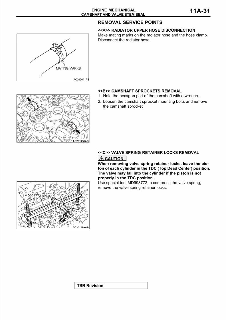
REMOVAL SERVICE POINTS.
<<A>> RADIATOR UPPER HOSE DISCONNECTION
Make mating marks on the radiator hose and the hose clamp.
Disconnect the radiator hose.
.
<<B>> CAMSHAFT SPROCKETS REMOVAL
1. Hold the hexagon part of the camshaft with a wrench.
2. Loosen the camshaft sprocket mounting bolts and remove
the camshaft sprocket.
.
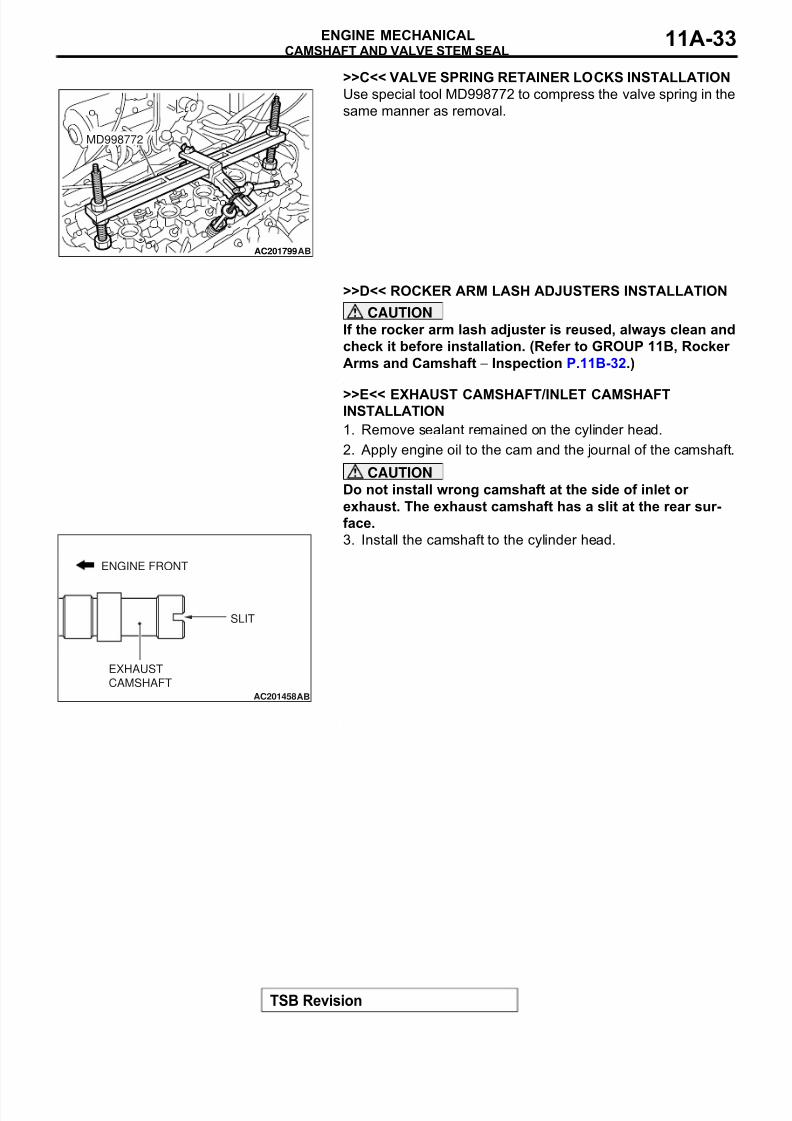
<<C>> VALVE SPRING RETAINER LOCKS REMOVAL
CAUTION
When removing valve spring retainer locks, leave the pis-
ton of each cylinder in the TDC (Top Dead Center) position.The valve may fall into the cylinder if the piston is not
properly in the TDC position.
Use special tool MD998772 to compress the valve spring,
remove the valve spring retainer locks.
AC200641AB
MATING MARKS
AC201457AB
AC201799
MD998772
AB
8/8/2019 GR00003800-11A
http://slidepdf.com/reader/full/gr00003800-11a 32/66
CAMSHAFT AND VALVE STEM SEAL
TSB Revision
ENGINE MECHANICAL11A-32
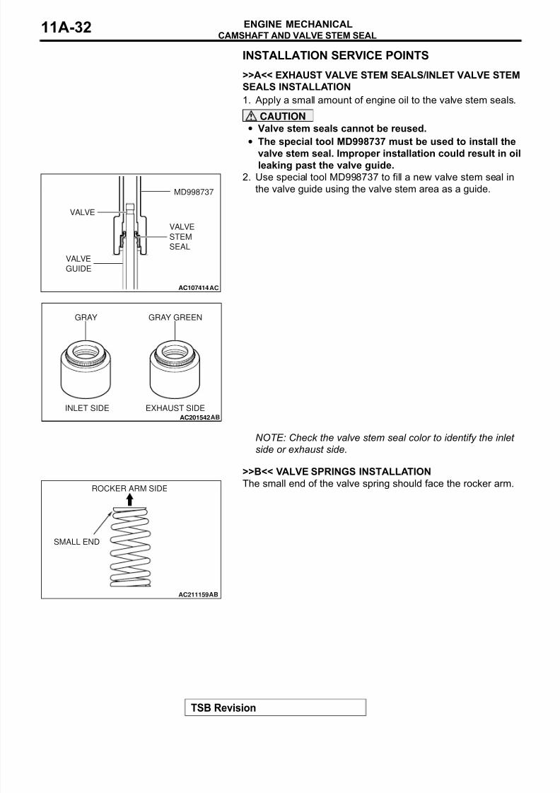
INSTALLATION SERVICE POINTS.
>>A<< EXHAUST VALVE STEM SEALS/INLET VALVE STEM
SEALS INSTALLATION
1. Apply a small amount of engine oil to the valve stem seals.
CAUTION
• Valve stem seals cannot be reused.
• The special tool MD998737 must be used to install thevalve stem seal. Improper installation could result in oil
leaking past the valve guide.
2. Use special tool MD998737 to fill a new valve stem seal in
the valve guide using the valve stem area as a guide.
NOTE: Check the valve stem seal color to identify the inlet
side or exhaust side..
>>B<< VALVE SPRINGS INSTALLATION
The small end of the valve spring should face the rocker arm.
.
AC107414AC
MD998737
VALVE
VALVE
STEM
SEAL
VALVE
GUIDE
AC201542AB
EXHAUST SIDEINLET SIDE
GRAY GRAY GREEN
AC211159AB
ROCKER ARM SIDE
SMALL END
8/8/2019 GR00003800-11A
http://slidepdf.com/reader/full/gr00003800-11a 33/66
8/8/2019 GR00003800-11A
http://slidepdf.com/reader/full/gr00003800-11a 34/66
CAMSHAFT AND VALVE STEM SEAL
TSB Revision
ENGINE MECHANICAL11A-34
>>F<< CAMSHAFT BEARING CAPS, NUMBER
4/CAMSHAFT BEARING CAPS, NUMBER 3/CAMSHAFT
BEARING CAPS, NUMBER 5/CAMSHAFT BEARING CAPS,
NUMBER 2/CAMSHAFT BEARING CAPS,
REAR/CAMSHAFT BEARING CAPS, FRONT
INSTALLATION
1. Set the dowel pin of the camshaft to the position as shown in
the illustration.
2. Since the shape of camshaft bearing caps number 2 − 5 is
identical, check the identification marks so that the bearing
cap No., inlet side, or exhaust side cannot be mistaken toinstall to the direction as shown in the illustration.
Identification mark (engraved on the front and bearing
caps number 2 − 5)
I: Inlet side
E: Exhaust side
3. Apply sealant to the positions (6 areas) of the upper side of
the cylinder head as shown in the illustration.
Specified sealant: 3Mä AAD Part No. 8672, 3Mä AAD
Part No. 8679/8678 or equivalent
4. Position the camshaft bearing caps, rear in the direction as
shown in the illustration for installation.
5. Check the identification marks on the camshaft bearing
caps, front so that inlet side and exhaust side cannot be
mistaken in the same way as that of bearing caps number 2− 5.
6. Tighten the bearing cap mounting bolts increasing the
pressure in 2 to 3 times and finally tighten to the specified
torque.
Tightening torque: 20 ± 1 N⋅m (14 ± 0.5 ft-lb)
7. Ensure that the rocker arms are installed properly.
NOTE: Remove an excess of sealant completely..
AC201459AB
APPROXIMATELY 3˚
DOWEL PIN
EXHAUST SIDEINLET SIDE
AC201460
E 4
AB
ENGINE FRONT
BEARING CAPNUMBER
IDENTIFICATION
OF INLET SIDE
AND EXHAUST
SIDE
AC201461AB
ENGINE FRONT
AC201462AB
ENGINE FRONT
FRONT
MARKING
8/8/2019 GR00003800-11A
http://slidepdf.com/reader/full/gr00003800-11a 35/66
CAMSHAFT AND VALVE STEM SEAL
TSB Revision
ENGINE MECHANICAL 11A-35
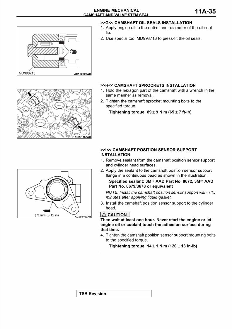
>>G<< CAMSHAFT OIL SEALS INSTALLATION
1. Apply engine oil to the entire inner diameter of the oil seal
lip.
2. Use special tool MD998713 to press-fit the oil seals.
.
>>H<< CAMSHAFT SPROCKETS INSTALLATION
1. Hold the hexagon part of the camshaft with a wrench in the
same manner as removal.
2. Tighten the camshaft sprocket mounting bolts to the
specified torque.
Tightening torque: 89 ± 9 N⋅m (65 ± 7 ft-lb)
.
>>I<< CAMSHAFT POSITION SENSOR SUPPORT
INSTALLATION
1. Remove sealant from the camshaft position sensor support
and cylinder head surfaces.
2. Apply the sealant to the camshaft position sensor support
flange in a continuous bead as shown in the illustration.
Specified sealant: 3Mä AAD Part No. 8672, 3Mä AAD
Part No. 8679/8678 or equivalent
NOTE: Install the camshaft position sensor support within 15
minutes after applying liquid gasket.
3. Install the camshaft position sensor support to the cylinder
head.
CAUTION
Then wait at least one hour. Never start the engine or let
engine oil or coolant touch the adhesion surface during
that time.4. Tighten the camshaft position sensor support mounting bolts
to the specified torque.
Tightening torque: 14 ± 1 N⋅m (120 ± 13 in-lb)
.
AC102323ABMD998713
AC201457AB
AC201463ABφ 3 mm (0.12 in)
8/8/2019 GR00003800-11A
http://slidepdf.com/reader/full/gr00003800-11a 36/66
CAMSHAFT AND VALVE STEM SEAL
TSB Revision
ENGINE MECHANICAL11A-36
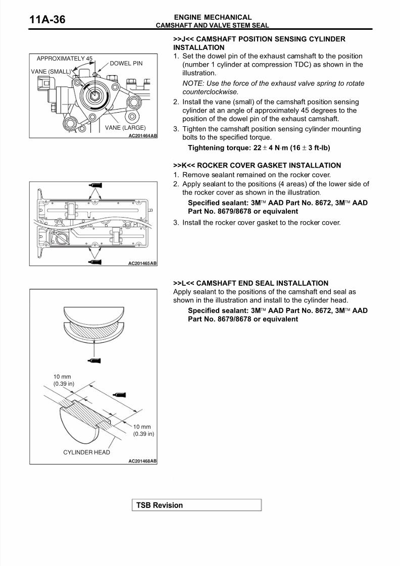
>>J<< CAMSHAFT POSITION SENSING CYLINDER
INSTALLATION
1. Set the dowel pin of the exhaust camshaft to the position
(number 1 cylinder at compression TDC) as shown in the
illustration.
NOTE: Use the force of the exhaust valve spring to rotate
counterclockwise.
2. Install the vane (small) of the camshaft position sensing
cylinder at an angle of approximately 45 degrees to the
position of the dowel pin of the exhaust camshaft.
3. Tighten the camshaft position sensing cylinder mounting
bolts to the specified torque.
Tightening torque: 22 ± 4 N⋅m (16 ± 3 ft-lb)
.
>>K<< ROCKER COVER GASKET INSTALLATION
1. Remove sealant remained on the rocker cover.
2. Apply sealant to the positions (4 areas) of the lower side of
the rocker cover as shown in the illustration.
Specified sealant: 3Mä AAD Part No. 8672, 3Mä AAD
Part No. 8679/8678 or equivalent
3. Install the rocker cover gasket to the rocker cover.
.
>>L<< CAMSHAFT END SEAL INSTALLATION
Apply sealant to the positions of the camshaft end seal as
shown in the illustration and install to the cylinder head.
Specified sealant: 3Mä AAD Part No. 8672, 3Mä AAD
Part No. 8679/8678 or equivalent
.
AC201464AB
APPROXIMATELY 45˚
DOWEL PIN
VANE (LARGE)
VANE (SMALL)
AC201465AB
AC201468AB
CYLINDER HEAD
10 mm
(0.39 in)
10 mm
(0.39 in)
8/8/2019 GR00003800-11A
http://slidepdf.com/reader/full/gr00003800-11a 37/66
CAMSHAFT AND VALVE STEM SEAL
TSB Revision
ENGINE MECHANICAL 11A-37
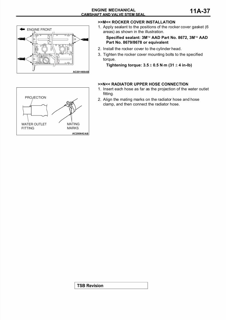
>>M<< ROCKER COVER INSTALLATION
1. Apply sealant to the positions of the rocker cover gasket (6
areas) as shown in the illustration.
Specified sealant: 3Mä AAD Part No. 8672, 3Mä AAD
Part No. 8679/8678 or equivalent
2. Install the rocker cover to the cylinder head.
3. Tighten the rocker cover mounting bolts to the specifiedtorque.
Tightening torque: 3.5 ± 0.5 N⋅m (31 ± 4 in-lb)
.
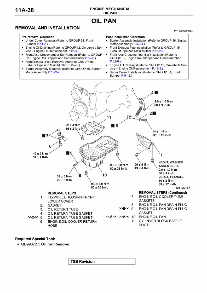
>>N<< RADIATOR UPPER HOSE CONNECTION
1. Insert each hose as far as the projection of the water outlet
fitting.
2. Align the mating marks on the radiator hose and hose
clamp, and then connect the radiator hose.
AC201469AB
ENGINE FRONT
AC200642
MATING
MARKS
PROJECTION
WATER OUTLET
FITTING
AB
8/8/2019 GR00003800-11A
http://slidepdf.com/reader/full/gr00003800-11a 38/66
OIL PAN
TSB Revision
ENGINE MECHANICAL11A-38
OIL PAN
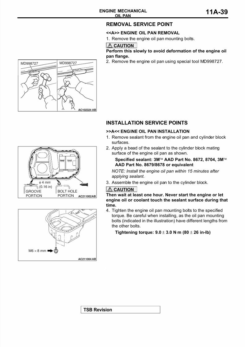
REMOVAL AND INSTALLATIONM1112002800495
Required Special Tool:
• MD998727: Oil Pan Remover
Pre-removal Operation
• Under Cover Removal (Refer to GROUP 51, FrontBumper P.51-2.)
• Engine Oil Draining (Refer to GROUP 12, On-vehicle Ser-
vice − Engine Oil Replacement P.12-3.)• Front Axle Crossmember Bar Removal (Refer to GROUP
32, Engine Roll Stopper and Centermember P.32-6.)
• Front Exhaust Pipe Removal (Refer to GROUP 15,Exhaust Pipe and Main Muffler P.15-23.)
• Starter Assembly Removal (Refer to GROUP 16, Starter Motor Assembly P.16-24.)
Post-installation Operation
• Starter Assembly Installation (Refer to GROUP 16, Starter Motor Assembly P.16-24.)
• Front Exhaust Pipe Installation (Refer to GROUP 15,
Exhaust Pipe and Main Muffler P.15-23.)• Front Axle Crossmember Bar Installation (Refer to
GROUP 32, Engine Roll Stopper and Centermember P.32-6.)
• Engine Oil Refilling (Refer to GROUP 12, On-vehicle Ser-vice − Engine Oil Replacement P.12-3.)
• Under Cover Installation (Refer to GROUP 51, FrontBumper P.51-2.)
AC210942
N
9.0 ± 3.0 N·m
80 ± 26 in-lb
9.0 ± 3.0 N·m
80 ± 26 in-lb
26 ± 5 N·m
19 ± 4 ft-lb
<BOLT, WASHER
ASSEMBLED>
9.0 ± 1.0 N·m
80 ± 9 in-lb
<BOLT, FLANGE>
10 ± 2 N·m
89 ± 17 in-lb
39 ± 5 N·m
29 ± 3 ft-lb
2
3
1
AB
10
9
8
7
6
5
11
4
N
N
22 ± 4 N·m
16 ± 3 ft-lb
42 ± 2 N·m31 ± 1 ft-lb
N
9.0 ± 1.0 N·m80 ± 9 in-lb
14 ± 1 N·m
120 ± 13 in-lb
N
REMOVAL STEPS
1. FLYWHEEL HOUSING FRONT
LOWER COVER
2. GASKET3. OIL RETURN TUBE
4. OIL RETURN TUBE GASKET>>C<< 5. OIL RETURN TUBE GASKET
6. ENGINE OIL COOLER RETURN
HOSE
7. ENGINE OIL COOLER TUBE
GASKETS
8. ENGINE OIL PAN DRAIN PLUG>>B<< 9. ENGINE OIL PAN DRAIN PLUG
GASKET<<A>> >>A<< 10. ENGINE OIL PAN
11. CYLINDER BLOCK BAFFLE
PLATE
REMOVAL STEPS (Continued)
8/8/2019 GR00003800-11A
http://slidepdf.com/reader/full/gr00003800-11a 39/66
OIL PAN
TSB Revision
ENGINE MECHANICAL 11A-39
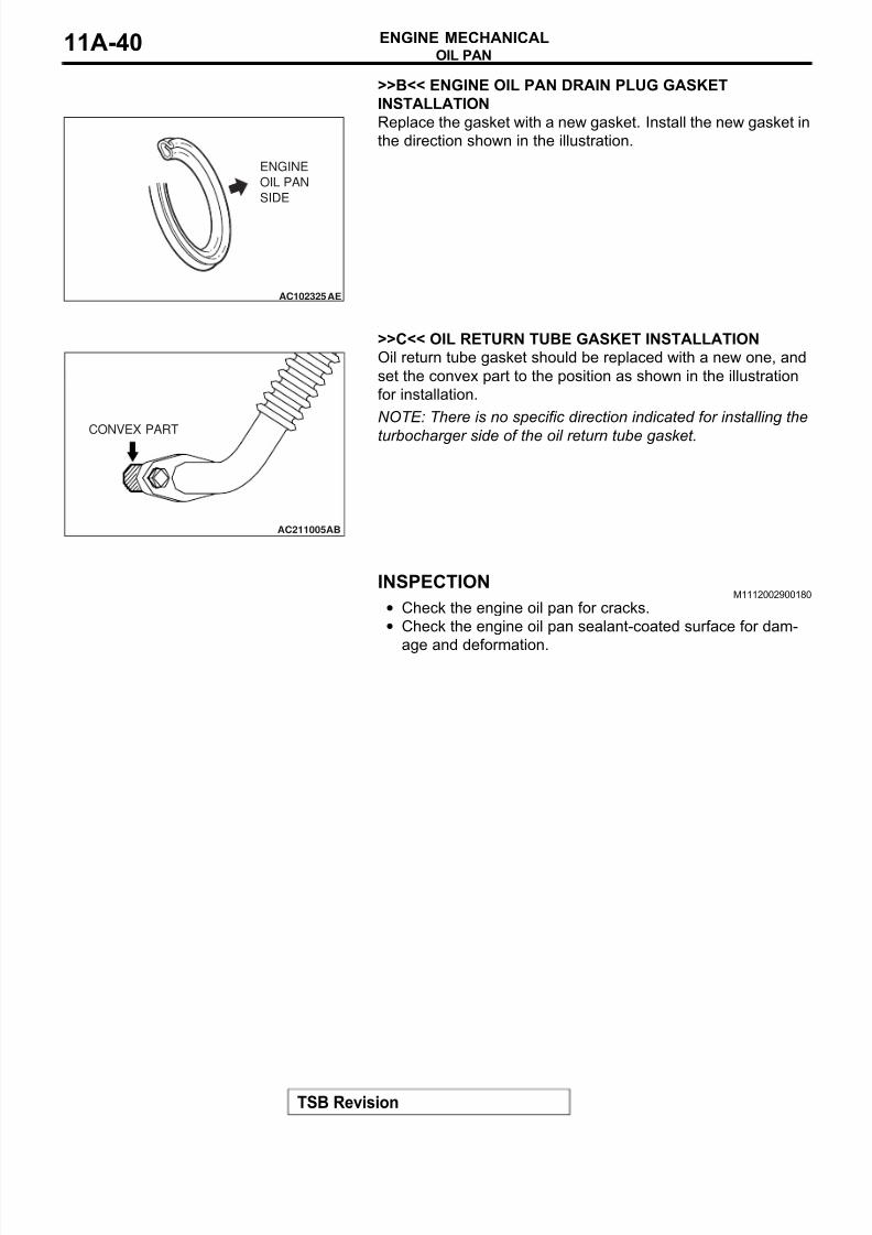
REMOVAL SERVICE POINT.
<<A>> ENGINE OIL PAN REMOVAL
1. Remove the engine oil pan mounting bolts.
CAUTION
Perform this slowly to avoid deformation of the engine oil
pan flange.
2. Remove the engine oil pan using special tool MD998727.
INSTALLATION SERVICE POINTS.
>>A<< ENGINE OIL PAN INSTALLATION
1. Remove sealant from the engine oil pan and cylinder block
surfaces.
2. Apply a bead of the sealant to the cylinder block mating
surface of the engine oil pan as shown.
Specified sealant: 3Mä AAD Part No. 8672, 8704, 3Mä
AAD Part No. 8679/8678 or equivalent
NOTE: Install the engine oil pan within 15 minutes after
applying sealant.
3. Assemble the engine oil pan to the cylinder block.
CAUTION
Then wait at least one hour. Never start the engine or let
engine oil or coolant touch the sealant surface during that
time.
4. Tighten the engine oil pan mounting bolts to the specified
torque. Be careful when installing, as the oil pan mounting
bolts (indicated in the illustration) have different lengths from
the other bolts.
Tightening torque: 9.0 ± 3.0 N⋅m (80 ± 26 in-lb)
.
AC102324AB
MD998727 MD998727
AC211002
GROOVE
PORTION
φ 4 mm(0.16 in)
BOLT HOLE
PORTION AB
AC211004
M6 × 8 mm
AB
8/8/2019 GR00003800-11A
http://slidepdf.com/reader/full/gr00003800-11a 40/66
OIL PAN
TSB Revision
ENGINE MECHANICAL11A-40
>>B<< ENGINE OIL PAN DRAIN PLUG GASKET
INSTALLATION
Replace the gasket with a new gasket. Install the new gasket in
the direction shown in the illustration.
.
>>C<< OIL RETURN TUBE GASKET INSTALLATION
Oil return tube gasket should be replaced with a new one, and
set the convex part to the position as shown in the illustration
for installation.
NOTE: There is no specific direction indicated for installing the
turbocharger side of the oil return tube gasket.
INSPECTIONM1112002900180
• Check the engine oil pan for cracks.
• Check the engine oil pan sealant-coated surface for dam-
age and deformation.
AC102325AE
ENGINE
OIL PAN
SIDE
AC211005AB
CONVEX PART
8/8/2019 GR00003800-11A
http://slidepdf.com/reader/full/gr00003800-11a 41/66
CRANKSHAFT OIL SEAL
TSB Revision
ENGINE MECHANICAL 11A-41
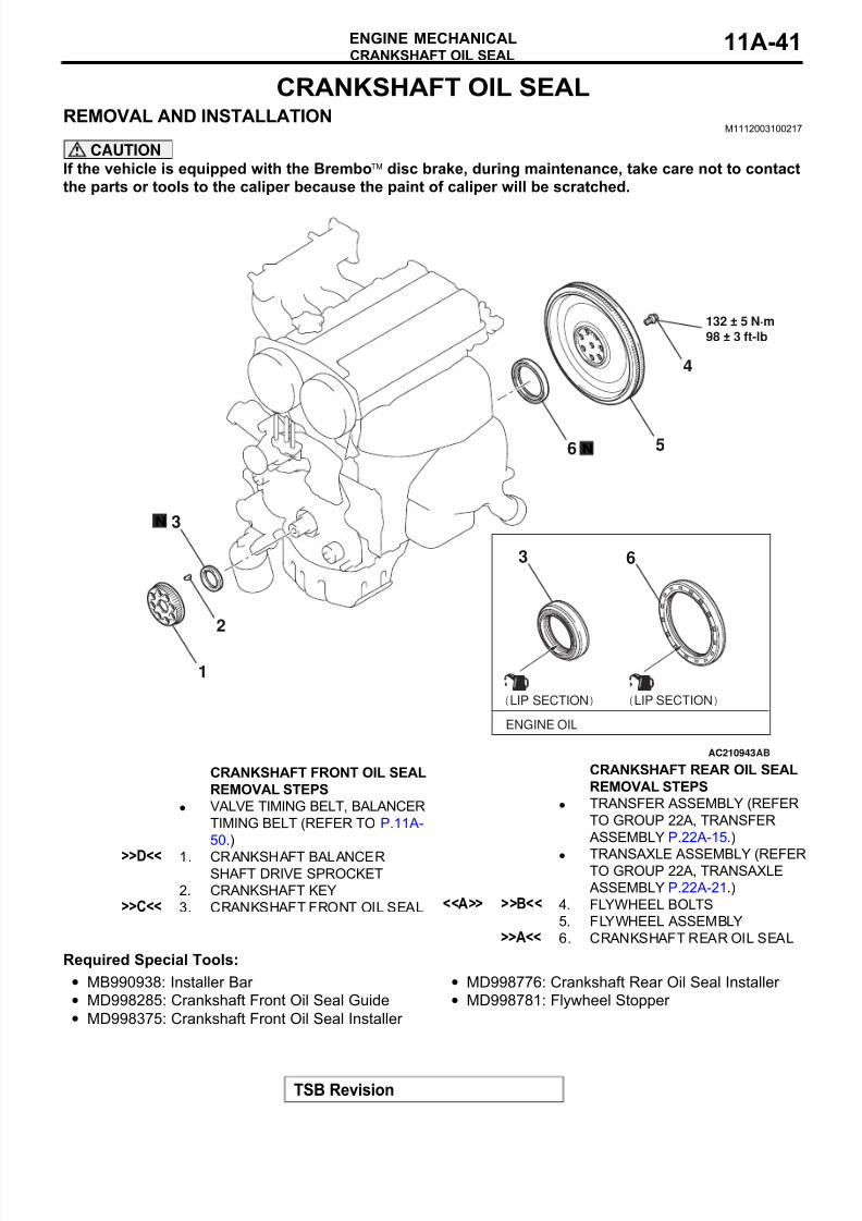
CRANKSHAFT OIL SEAL
REMOVAL AND INSTALLATIONM1112003100217
CAUTION
If the vehicle is equipped with the Bremboä disc brake, during maintenance, take care not to contact
the parts or tools to the caliper because the paint of caliper will be scratched.
Required Special Tools:
• MB990938: Installer Bar
• MD998285: Crankshaft Front Oil Seal Guide
• MD998375: Crankshaft Front Oil Seal Installer
• MD998776: Crankshaft Rear Oil Seal Installer
• MD998781: Flywheel Stopper
AC210943AB
1
2
3
(LIP SECTION)
ENGINE OIL
3 6
6 5
4
N
N
132 ± 5 N·m
98 ± 3 ft-lb
(LIP SECTION)
CRANKSHAFT FRONT OIL SEAL
REMOVAL STEPS
• VALVE TIMING BELT, BALANCER
TIMING BELT (REFER TO P.11A-
50.)
>>D<< 1. CRANKSHAFT BALANCERSHAFT DRIVE SPROCKET
2. CRANKSHAFT KEY>>C<< 3. CRANKSHAFT FRONT OIL SEAL
CRANKSHAFT REAR OIL SEAL
REMOVAL STEPS
• TRANSFER ASSEMBLY (REFER
TO GROUP 22A, TRANSFER
ASSEMBLY P.22A-15.)
• TRANSAXLE ASSEMBLY (REFERTO GROUP 22A, TRANSAXLE
ASSEMBLY P.22A-21.)<<A>> >>B<< 4. FLYWHEEL BOLTS
5. FLYWHEEL ASSEMBLY>>A<< 6. CRANKSHAFT REAR OIL SEAL
8/8/2019 GR00003800-11A
http://slidepdf.com/reader/full/gr00003800-11a 42/66
CRANKSHAFT OIL SEAL
TSB Revision
ENGINE MECHANICAL11A-42
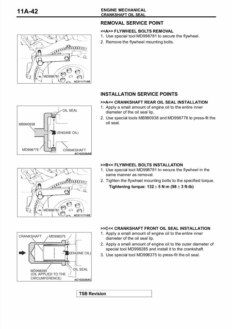
REMOVAL SERVICE POINT.
<<A>> FLYWHEEL BOLTS REMOVAL
1. Use special tool MD998781 to secure the flywheel.
2. Remove the flywheel mounting bolts.
INSTALLATION SERVICE POINTS.
>>A<< CRANKSHAFT REAR OIL SEAL INSTALLATION
1. Apply a small amount of engine oil to the entire inner
diameter of the oil seal lip.
2. Use special tools MB990938 and MD998776 to press-fit the
oil seal.
.
>>B<< FLYWHEEL BOLTS INSTALLATION
1. Use special tool MD998781 to secure the flywheel in the
same manner as removal.
2. Tighten the flywheel mounting bolts to the specified torque.
Tightening torque: 132 ± 5 N⋅m (98 ± 3 ft-lb)
.
>>C<< CRANKSHAFT FRONT OIL SEAL INSTALLATION1. Apply a small amount of engine oil to the entire inner
diameter of the oil seal lip.
2. Apply a small amount of engine oil to the outer diameter of
special tool MD998285 and install it to the crankshaft.
3. Use special tool MD998375 to press-fit the oil seal.
.
AC211171AB
MD998781
AC102328AB
OIL SEAL
MB990938
MD998776 CRANKSHAFT
(ENGINE OIL)
AC211171AB
MD998781
AC102329AC
MD998285
(ENGINE OIL)
(OIL APPLIED TO THE
CIRCUMFERENCE)
OIL SEAL
CRANKSHAFT MD998375
8/8/2019 GR00003800-11A
http://slidepdf.com/reader/full/gr00003800-11a 43/66
CRANKSHAFT OIL SEAL
TSB Revision
ENGINE MECHANICAL 11A-43
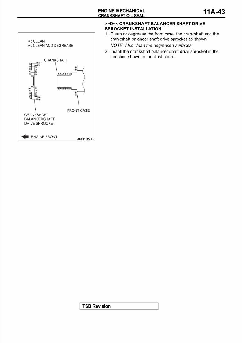
>>D<< CRANKSHAFT BALANCER SHAFT DRIVE
SPROCKET INSTALLATION
1. Clean or degrease the front case, the crankshaft and the
crankshaft balancer shaft drive sprocket as shown.
NOTE: Also clean the degreased surfaces.
2. Install the crankshaft balancer shaft drive sprocket in the
direction shown in the illustration.
AC211222
CRANKSHAFT
BALANCERSHAFTDRIVE SPROCKET
ENGINE FRONT
FRONT CASE
CRANKSHAFT
AB
: CLEAN
: CLEAN AND DEGREASE
8/8/2019 GR00003800-11A
http://slidepdf.com/reader/full/gr00003800-11a 44/66
CYLINDER HEAD GASKET
TSB Revision
ENGINE MECHANICAL11A-44
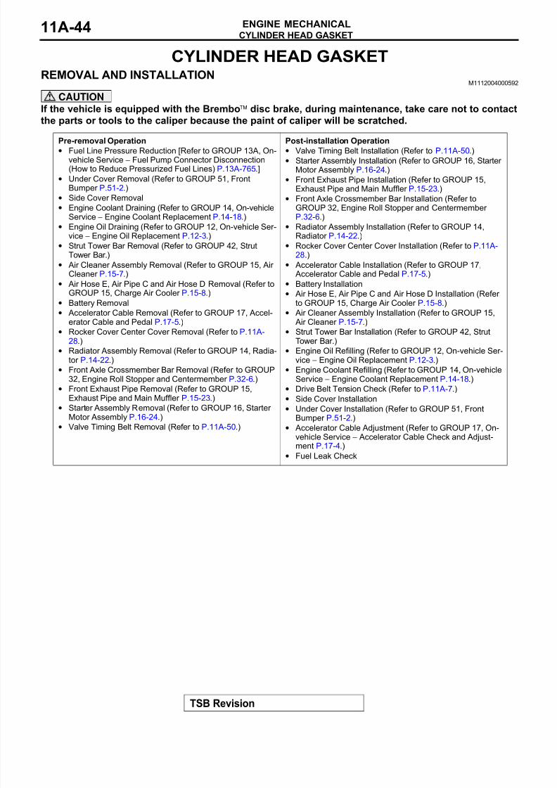
CYLINDER HEAD GASKET
REMOVAL AND INSTALLATIONM1112004000592
CAUTION
If the vehicle is equipped with the Bremboä disc brake, during maintenance, take care not to contact
the parts or tools to the caliper because the paint of caliper will be scratched.
Pre-removal Operation• Fuel Line Pressure Reduction [Refer to GROUP 13A, On-
vehicle Service − Fuel Pump Connector Disconnection(How to Reduce Pressurized Fuel Lines) P.13A-765.]
• Under Cover Removal (Refer to GROUP 51, FrontBumper P.51-2.)
• Side Cover Removal
• Engine Coolant Draining (Refer to GROUP 14, On-vehicleService − Engine Coolant Replacement P.14-18.)
• Engine Oil Draining (Refer to GROUP 12, On-vehicle Ser-vice − Engine Oil Replacement P.12-3.)
• Strut Tower Bar Removal (Refer to GROUP 42, StrutTower Bar.)
• Air Cleaner Assembly Removal (Refer to GROUP 15, Air
Cleaner P.15-7.)• Air Hose E, Air Pipe C and Air Hose D Removal (Refer to
GROUP 15, Charge Air Cooler P.15-8.)
• Battery Removal
• Accelerator Cable Removal (Refer to GROUP 17, Accel-erator Cable and Pedal P.17-5.)
• Rocker Cover Center Cover Removal (Refer to P.11A-28.)
• Radiator Assembly Removal (Refer to GROUP 14, Radia-tor P.14-22.)
• Front Axle Crossmember Bar Removal (Refer to GROUP32, Engine Roll Stopper and Centermember P.32-6.)
• Front Exhaust Pipe Removal (Refer to GROUP 15,Exhaust Pipe and Main Muffler P.15-23.)
• Starter Assembly Removal (Refer to GROUP 16, Starter Motor Assembly P.16-24.)
• Valve Timing Belt Removal (Refer to P.11A-50.)
Post-installation Operation• Valve Timing Belt Installation (Refer to P.11A-50.)
• Starter Assembly Installation (Refer to GROUP 16, Starter Motor Assembly P.16-24.)
• Front Exhaust Pipe Installation (Refer to GROUP 15,Exhaust Pipe and Main Muffler P.15-23.)
• Front Axle Crossmember Bar Installation (Refer toGROUP 32, Engine Roll Stopper and Centermember P.32-6.)
• Radiator Assembly Installation (Refer to GROUP 14,Radiator P.14-22.)
• Rocker Cover Center Cover Installation (Refer to P.11A-28.)
• Accelerator Cable Installation (Refer to GROUP 17,
Accelerator Cable and Pedal P.17-5.)• Battery Installation
• Air Hose E, Air Pipe C and Air Hose D Installation (Refer to GROUP 15, Charge Air Cooler P.15-8.)
• Air Cleaner Assembly Installation (Refer to GROUP 15,Air Cleaner P.15-7.)
• Strut Tower Bar Installation (Refer to GROUP 42, StrutTower Bar.)
• Engine Oil Refilling (Refer to GROUP 12, On-vehicle Ser-vice − Engine Oil Replacement P.12-3.)
• Engine Coolant Refilling (Refer to GROUP 14, On-vehicleService − Engine Coolant Replacement P.14-18.)
• Drive Belt Tension Check (Refer to P.11A-7.)
• Side Cover Installation
• Under Cover Installation (Refer to GROUP 51, FrontBumper P.51-2.)
• Accelerator Cable Adjustment (Refer to GROUP 17, On-vehicle Service − Accelerator Cable Check and Adjust-ment P.17-4.)
• Fuel Leak Check
8/8/2019 GR00003800-11A
http://slidepdf.com/reader/full/gr00003800-11a 45/66
8/8/2019 GR00003800-11A
http://slidepdf.com/reader/full/gr00003800-11a 46/66
8/8/2019 GR00003800-11A
http://slidepdf.com/reader/full/gr00003800-11a 47/66
CYLINDER HEAD GASKET
TSB Revision
ENGINE MECHANICAL 11A-47
Required Special Tool:
• MB991654: Cylinder Head Bolt Wrench (12)
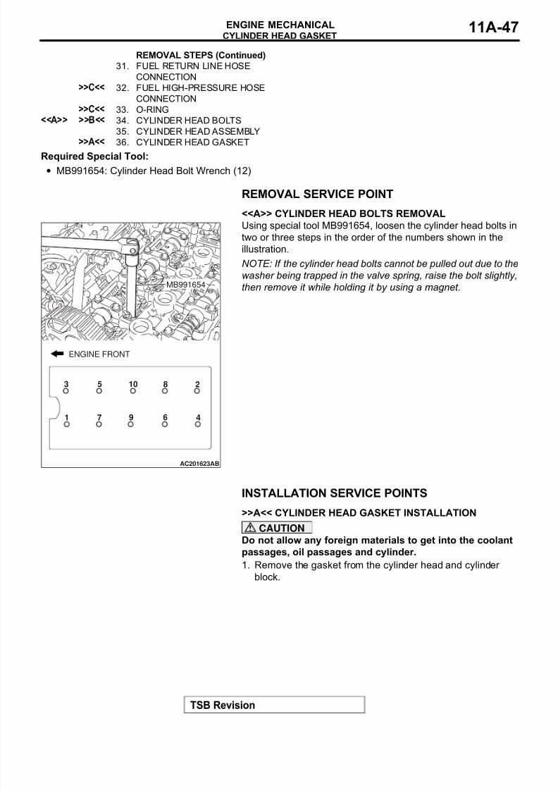
REMOVAL SERVICE POINT.
<<A>> CYLINDER HEAD BOLTS REMOVAL
Using special tool MB991654, loosen the cylinder head bolts in
two or three steps in the order of the numbers shown in the
illustration.
NOTE: If the cylinder head bolts cannot be pulled out due to the
washer being trapped in the valve spring, raise the bolt slightly,then remove it while holding it by using a magnet.
INSTALLATION SERVICE POINTS.
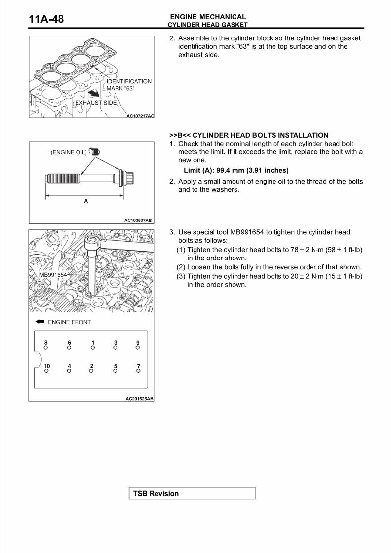
>>A<< CYLINDER HEAD GASKET INSTALLATION
CAUTION
Do not allow any foreign materials to get into the coolant
passages, oil passages and cylinder.1. Remove the gasket from the cylinder head and cylinder
block.
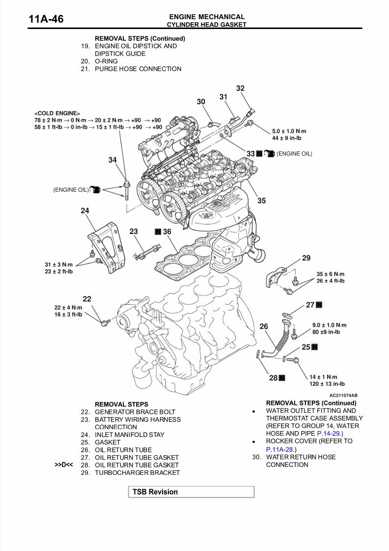
31. FUEL RETURN LINE HOSE
CONNECTION>>C<< 32. FUEL HIGH-PRESSURE HOSE
CONNECTION>>C<< 33. O-RING
<<A>> >>B<< 34. CYLINDER HEAD BOLTS
35. CYLINDER HEAD ASSEMBLY
>>A<< 36. CYLINDER HEAD GASKET
REMOVAL STEPS (Continued)
AC201623
MB991654
1
2
4697
3 5 10 8
AB
ENGINE FRONT
8/8/2019 GR00003800-11A
http://slidepdf.com/reader/full/gr00003800-11a 48/66
8/8/2019 GR00003800-11A
http://slidepdf.com/reader/full/gr00003800-11a 49/66
CYLINDER HEAD GASKET
TSB Revision
ENGINE MECHANICAL 11A-49
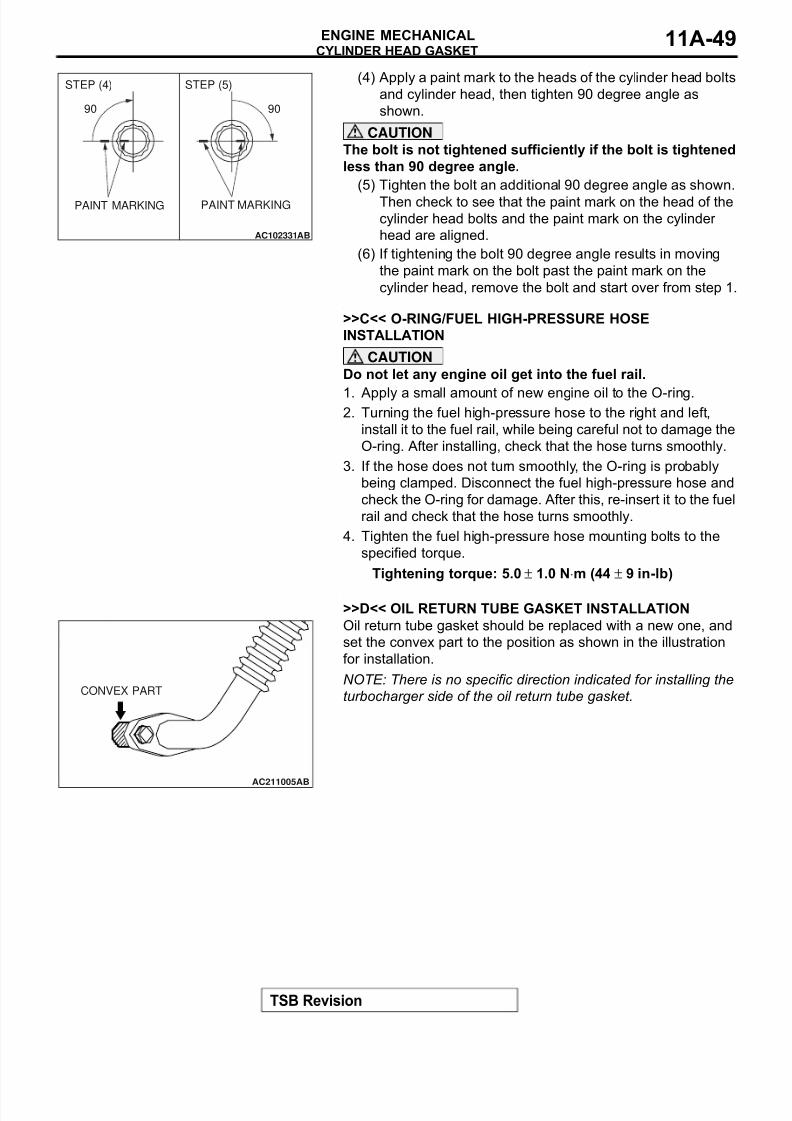
(4) Apply a paint mark to the heads of the cylinder head bolts
and cylinder head, then tighten 90 degree angle as
shown.
CAUTION
The bolt is not tightened sufficiently if the bolt is tightened
less than 90 degree angle.
(5) Tighten the bolt an additional 90 degree angle as shown.
Then check to see that the paint mark on the head of the
cylinder head bolts and the paint mark on the cylinder
head are aligned.
(6) If tightening the bolt 90 degree angle results in moving
the paint mark on the bolt past the paint mark on the
cylinder head, remove the bolt and start over from step 1..
>>C<< O-RING/FUEL HIGH-PRESSURE HOSE
INSTALLATION
CAUTION
Do not let any engine oil get into the fuel rail.
1. Apply a small amount of new engine oil to the O-ring.2. Turning the fuel high-pressure hose to the right and left,
install it to the fuel rail, while being careful not to damage the
O-ring. After installing, check that the hose turns smoothly.
3. If the hose does not turn smoothly, the O-ring is probably
being clamped. Disconnect the fuel high-pressure hose and
check the O-ring for damage. After this, re-insert it to the fuel
rail and check that the hose turns smoothly.
4. Tighten the fuel high-pressure hose mounting bolts to the
specified torque.
Tightening torque: 5.0 ± 1.0 N⋅m (44 ± 9 in-lb)
.
>>D<< OIL RETURN TUBE GASKET INSTALLATION
Oil return tube gasket should be replaced with a new one, and
set the convex part to the position as shown in the illustration
for installation.
NOTE: There is no specific direction indicated for installing the
turbocharger side of the oil return tube gasket.
AC102331AB
PAINT MARKING
90˚ 90˚
PAINT MARKING
STEP (4) STEP (5)
AC211005AB
CONVEX PART
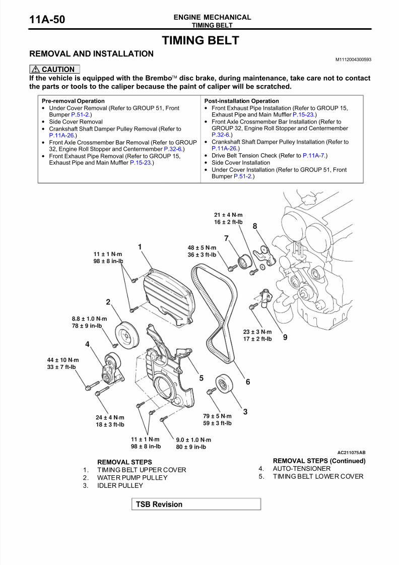
8/8/2019 GR00003800-11A
http://slidepdf.com/reader/full/gr00003800-11a 50/66
TIMING BELT
TSB Revision
ENGINE MECHANICAL11A-50
TIMING BELT
REMOVAL AND INSTALLATIONM1112004300593
CAUTION
If the vehicle is equipped with the Bremboä disc brake, during maintenance, take care not to contact
the parts or tools to the caliper because the paint of caliper will be scratched.
Pre-removal Operation• Under Cover Removal (Refer to GROUP 51, Front
Bumper P.51-2.)
• Side Cover Removal
• Crankshaft Shaft Damper Pulley Removal (Refer toP.11A-26.)
• Front Axle Crossmember Bar Removal (Refer to GROUP32, Engine Roll Stopper and Centermember P.32-6.)
• Front Exhaust Pipe Removal (Refer to GROUP 15,Exhaust Pipe and Main Muffler P.15-23.)
Post-installation Operation• Front Exhaust Pipe Installation (Refer to GROUP 15,
Exhaust Pipe and Main Muffler P.15-23.)
• Front Axle Crossmember Bar Installation (Refer toGROUP 32, Engine Roll Stopper and Centermember P.32-6.)
• Crankshaft Shaft Damper Pulley Installation (Refer toP.11A-26.)
• Drive Belt Tension Check (Refer to P.11A-7.)
• Side Cover Installation
• Under Cover Installation (Refer to GROUP 51, FrontBumper P.51-2.)
AC211075
9
7
6
8
23 ± 3 N·m
17 ± 2 ft-lb
48 ± 5 N·m
36 ± 3 ft-lb
21 ± 4 N·m
16 ± 2 ft-lb
AB
379 ± 5 N·m
59 ± 3 ft-lb
9.0 ± 1.0 N·m
80 ± 9 in-lb
11 ± 1 N·m
98 ± 8 in-lb
24 ± 4 N·m
18 ± 3 ft-lb
44 ± 10 N·m
33 ± 7 ft-lb
5
2
8.8 ± 1.0 N·m
78 ± 9 in-lb
4
11 ± 1 N·m
98 ± 8 in-lb
1
REMOVAL STEPS
1. TIMING BELT UPPER COVER
2. WATER PUMP PULLEY
3. IDLER PULLEY
4. AUTO-TENSIONER
5. TIMING BELT LOWER COVER
REMOVAL STEPS (Continued)
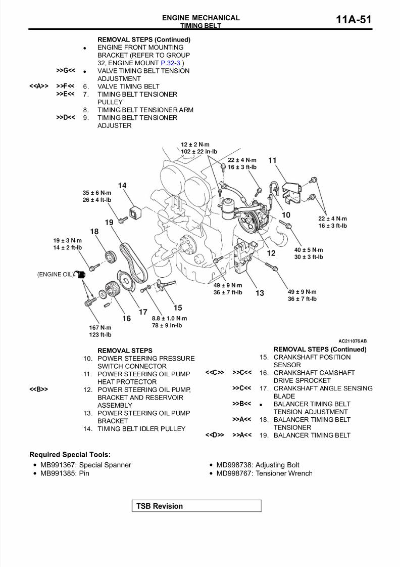
8/8/2019 GR00003800-11A
http://slidepdf.com/reader/full/gr00003800-11a 51/66
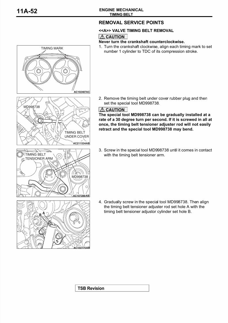
8/8/2019 GR00003800-11A
http://slidepdf.com/reader/full/gr00003800-11a 52/66
TIMING BELT
TSB Revision
ENGINE MECHANICAL11A-52
REMOVAL SERVICE POINTS.
<<A>> VALVE TIMING BELT REMOVAL
CAUTION
Never turn the crankshaft counterclockwise.
1. Turn the crankshaft clockwise, align each timing mark to set
number 1 cylinder to TDC of its compression stroke.
2. Remove the timing belt under cover rubber plug and then
set the special tool MD998738.
CAUTION
The special tool MD998738 can be gradually installed at arate of a 30 degree turn per second. If it is screwed in all at
once, the timing belt tensioner adjuster rod will not easily
retract and the special tool MD998738 may bend.
3. Screw in the special tool MD998738 until it comes in contact
with the timing belt tensioner arm.
4. Gradually screw in the special tool MD998738. Then align
the timing belt tensioner adjuster rod set hole A with the
timing belt tensioner adjustor cylinder set hole B.
AC102487
TIMING MARK
AC
AC211534AB
MD998738
TIMING BELT
UNDER COVER
AC107289
MD998738
TIMING BELT
TENSIONER ARM
AB
AC102775AB
AB
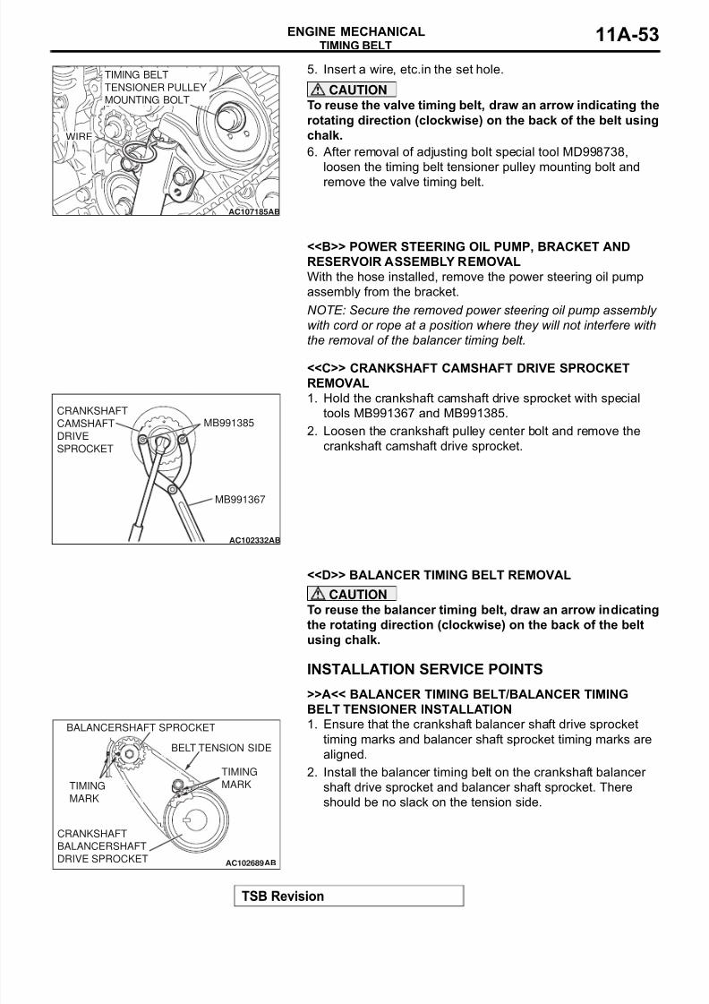
8/8/2019 GR00003800-11A
http://slidepdf.com/reader/full/gr00003800-11a 53/66
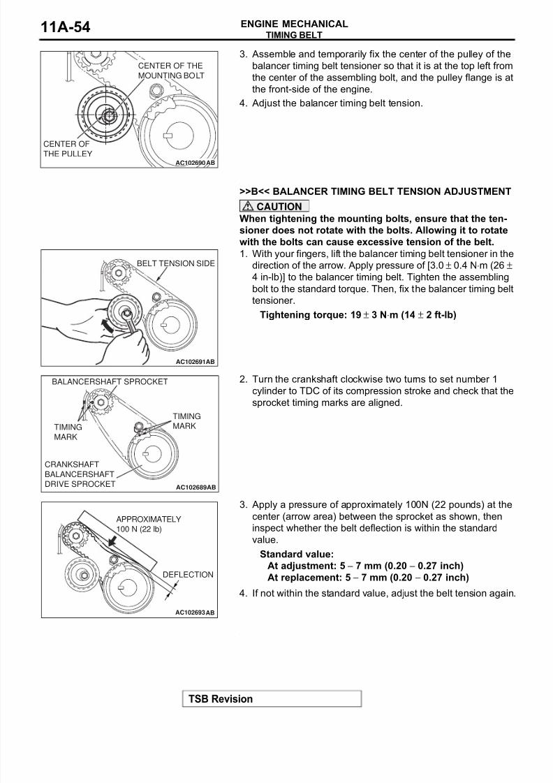
8/8/2019 GR00003800-11A
http://slidepdf.com/reader/full/gr00003800-11a 54/66
TIMING BELT
TSB Revision
ENGINE MECHANICAL11A-54
3. Assemble and temporarily fix the center of the pulley of the
balancer timing belt tensioner so that it is at the top left from
the center of the assembling bolt, and the pulley flange is at
the front-side of the engine.
4. Adjust the balancer timing belt tension.
.
>>B<< BALANCER TIMING BELT TENSION ADJUSTMENT
CAUTION
When tightening the mounting bolts, ensure that the ten-
sioner does not rotate with the bolts. Allowing it to rotate
with the bolts can cause excessive tension of the belt.
1. With your fingers, lift the balancer timing belt tensioner in the
direction of the arrow. Apply pressure of [3.0 ± 0.4 N⋅m (26 ±
4 in-lb)] to the balancer timing belt. Tighten the assemblingbolt to the standard torque. Then, fix the balancer timing belt
tensioner.
Tightening torque: 19 ± 3 N⋅m (14 ± 2 ft-lb)
2. Turn the crankshaft clockwise two turns to set number 1
cylinder to TDC of its compression stroke and check that the
sprocket timing marks are aligned.
3. Apply a pressure of approximately 100N (22 pounds) at the
center (arrow area) between the sprocket as shown, then
inspect whether the belt deflection is within the standard
value.
Standard value:
At adjustment: 5 − 7 mm (0.20 − 0.27 inch)
At replacement: 5 − 7 mm (0.20 − 0.27 inch)
4. If not within the standard value, adjust the belt tension again.
.
AC102690AB
CENTER OF
THE PULLEY
CENTER OF THE
MOUNTING BOLT
AC102691AB
BELT TENSION SIDE
AC102689AB
BALANCERSHAFT SPROCKET
TIMING
MARKTIMING
MARK
CRANKSHAFT
BALANCERSHAFT
DRIVE SPROCKET
AC102693AB
DEFLECTION
APPROXIMATELY
100 N (22 lb)
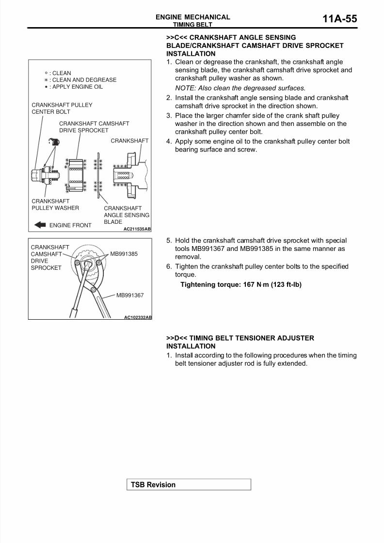
8/8/2019 GR00003800-11A
http://slidepdf.com/reader/full/gr00003800-11a 55/66
TIMING BELT
TSB Revision
ENGINE MECHANICAL 11A-55
>>C<< CRANKSHAFT ANGLE SENSING
BLADE/CRANKSHAFT CAMSHAFT DRIVE SPROCKET
INSTALLATION
1. Clean or degrease the crankshaft, the crankshaft angle
sensing blade, the crankshaft camshaft drive sprocket and
crankshaft pulley washer as shown.
NOTE: Also clean the degreased surfaces.
2. Install the crankshaft angle sensing blade and crankshaft
camshaft drive sprocket in the direction shown.
3. Place the larger chamfer side of the crank shaft pulley
washer in the direction shown and then assemble on the
crankshaft pulley center bolt.
4. Apply some engine oil to the crankshaft pulley center bolt
bearing surface and screw.
5. Hold the crankshaft camshaft drive sprocket with special
tools MB991367 and MB991385 in the same manner as
removal.
6. Tighten the crankshaft pulley center bolts to the specified
torque.
Tightening torque: 167 N⋅m (123 ft-lb)
.
>>D<< TIMING BELT TENSIONER ADJUSTER
INSTALLATION
1. Install according to the following procedures when the timing
belt tensioner adjuster rod is fully extended.
AC211535ENGINE FRONT
AB
CRANKSHAFT CAMSHAFT
DRIVE SPROCKET
CRANKSHAFT PULLEY
CENTER BOLT
CRANKSHAFT
PULLEY WASHER CRANKSHAFT
ANGLE SENSING
BLADE
CRANKSHAFT
: CLEAN
: CLEAN AND DEGREASE
: APPLY ENGINE OIL
AC102332AB
MB991385
MB991367
CRANKSHAFT
CAMSHAFT
DRIVE
SPROCKET
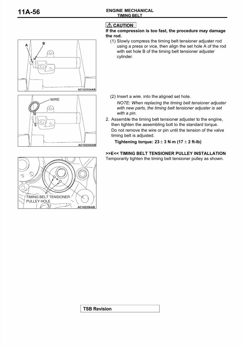
8/8/2019 GR00003800-11A
http://slidepdf.com/reader/full/gr00003800-11a 56/66
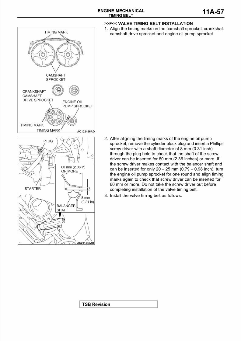
8/8/2019 GR00003800-11A
http://slidepdf.com/reader/full/gr00003800-11a 57/66
TIMING BELT
TSB Revision
ENGINE MECHANICAL 11A-57
>>F<< VALVE TIMING BELT INSTALLATION
1. Align the timing marks on the camshaft sprocket, crankshaft
camshaft drive sprocket and engine oil pump sprocket.
2. After aligning the timing marks of the engine oil pump
sprocket, remove the cylinder block plug and insert a Phillips
screw driver with a shaft diameter of 8 mm (0.31 inch)
through the plug hole to check that the shaft of the screw
driver can be inserted for 60 mm (2.36 inches) or more. If
the screw driver makes contact with the balancer shaft and
can be inserted for only 20 − 25 mm (0.79 − 0.98 inch), turn
the engine oil pump sprocket for one round and align timing
marks again to check that screw driver can be inserted for 60 mm or more. Do not take the screw driver out before
completing installation of the valve timing belt.
3. Install the valve timing belt as follows:
AC102486ADTIMING MARK
TIMING MARK
CRANKSHAFT
CAMSHAFT
DRIVE SPROCKETENGINE OIL
PUMP SPROCKET
CAMSHAFT
SPROCKET
TIMING MARK
AC211545
BALANCER
SHAFT
60 mm (2.36 in)
OR MORE
8 mm
(0.31 in)
AB
STARTER
PLUG
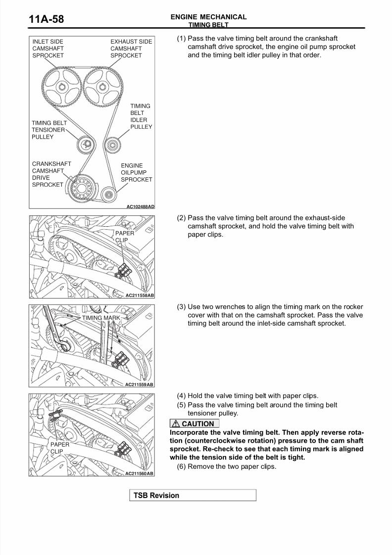
8/8/2019 GR00003800-11A
http://slidepdf.com/reader/full/gr00003800-11a 58/66

8/8/2019 GR00003800-11A
http://slidepdf.com/reader/full/gr00003800-11a 59/66
TIMING BELT
TSB Revision
ENGINE MECHANICAL 11A-59
4. Turn the timing belt tensioner in the direction shown using
special tool MD998767 to apply tension to the valve timing
belt. Then pre-tighten the timing belt tensioner pulley.
5. Check that the timing marks are aligned.
6. Remove the Phillips screw driver inserted in Step 2 above,
then assemble the cylinder block plug.
7. Tighten the cylinder block plug to the specified torque.
Tightening torque: 30 ± 3 N⋅m (23 ± 2 ft-lb)
8. Adjust the valve timing belt tension.
.
>>G<< VALVE TIMING BELT TENSION ADJUSTMENT
1. Set special tool MD998738 when removing the valve timing
belt.
CAUTION
Always screw in special tool MD998738 by hand, since use
of a spanner or other tools may damage the wire or pin
inserted in the timing belt tensioner adjuster.
2. Gradually screw in special tool MD998738 until the wire or
pin inserted in the timing belt tensioner adjuster lightlymoves.
3. Turn the crankshaft 1/4 turn counterclockwise.
4. Turn the crankshaft in the clockwise direction until you align
each timing mark to set number 1 cylinder to TDC of its
compression stroke.
5. Loosen the timing belt tensioner pulley mounting bolt.
AC102694AB
MD998767
AC211564AB
PLUG
SCREW
DRIVER
AC211534AB
MD998738
TIMING BELT
UNDER COVER

8/8/2019 GR00003800-11A
http://slidepdf.com/reader/full/gr00003800-11a 60/66
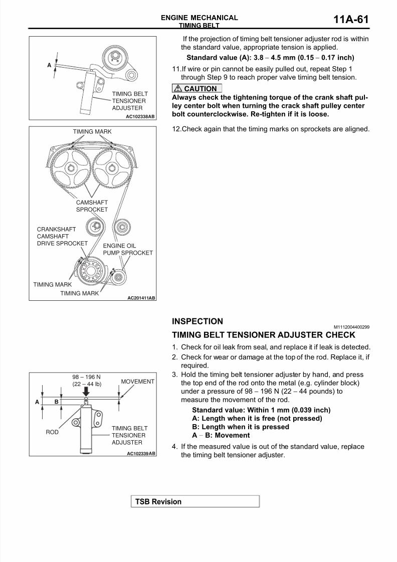
8/8/2019 GR00003800-11A
http://slidepdf.com/reader/full/gr00003800-11a 61/66
TIMING BELT
TSB Revision
ENGINE MECHANICAL 11A-61
If the projection of timing belt tensioner adjuster rod is within
the standard value, appropriate tension is applied.
Standard value (A): 3.8 − 4.5 mm (0.15 − 0.17 inch)
11.If wire or pin cannot be easily pulled out, repeat Step 1
through Step 9 to reach proper valve timing belt tension.
CAUTION
Always check the tightening torque of the crank shaft pul-ley center bolt when turning the crack shaft pulley center
bolt counterclockwise. Re-tighten if it is loose.
12.Check again that the timing marks on sprockets are aligned.
INSPECTIONM1112004400299
TIMING BELT TENSIONER ADJUSTER CHECK
1. Check for oil leak from seal, and replace it if leak is detected.
2. Check for wear or damage at the top of the rod. Replace it, if
required.
3. Hold the timing belt tensioner adjuster by hand, and press
the top end of the rod onto the metal (e.g. cylinder block)
under a pressure of 98 − 196 N (22 − 44 pounds) tomeasure the movement of the rod.
Standard value: Within 1 mm (0.039 inch)
A: Length when it is free (not pressed)
B: Length when it is pressed
A − B: Movement
4. If the measured value is out of the standard value, replace
the timing belt tensioner adjuster.
AC102338AB
TIMING BELT
TENSIONER
ADJUSTER
A
AC201411ABTIMING MARK
TIMING MARK
CRANKSHAFT
CAMSHAFT
DRIVE SPROCKET
TIMING MARK
CAMSHAFT
SPROCKET
ENGINE OIL
PUMP SPROCKET
AC102339AB
98 – 196 N
(22 – 44 lb)
RODTIMING BELT
TENSIONER
ADJUSTER
MOVEMENT
BA
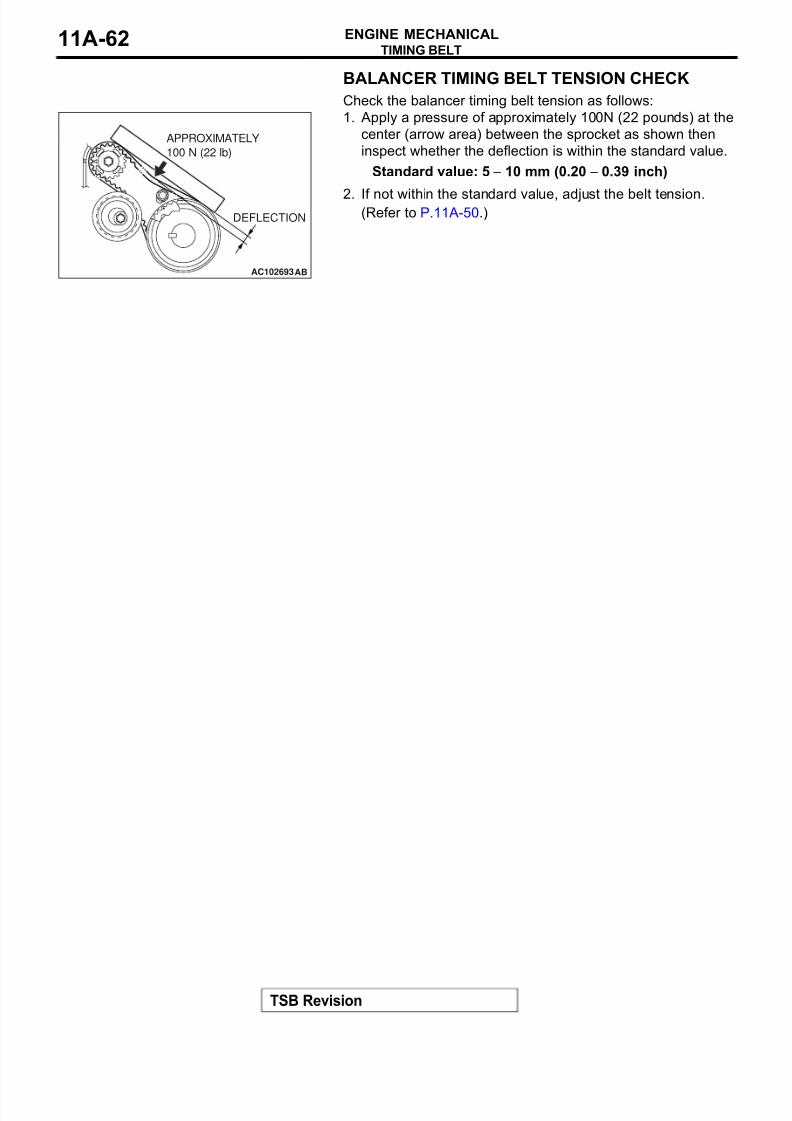
8/8/2019 GR00003800-11A
http://slidepdf.com/reader/full/gr00003800-11a 62/66
TIMING BELT
TSB Revision
ENGINE MECHANICAL11A-62
BALANCER TIMING BELT TENSION CHECK
Check the balancer timing belt tension as follows:
1. Apply a pressure of approximately 100N (22 pounds) at the
center (arrow area) between the sprocket as shown then
inspect whether the deflection is within the standard value.
Standard value: 5 − 10 mm (0.20 − 0.39 inch)
2. If not within the standard value, adjust the belt tension.(Refer to P.11A-50.)
AC102693AB
DEFLECTION
APPROXIMATELY
100 N (22 lb)
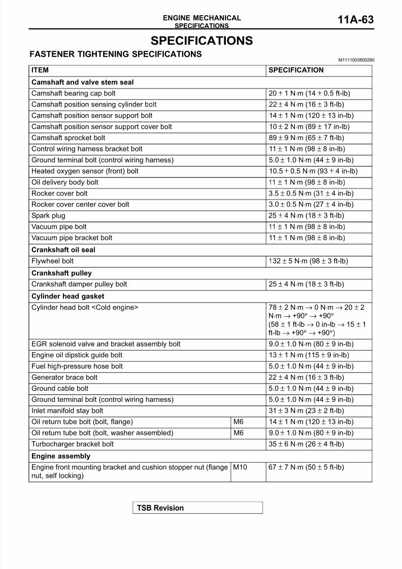
8/8/2019 GR00003800-11A
http://slidepdf.com/reader/full/gr00003800-11a 63/66
SPECIFICATIONS
TSB Revision
ENGINE MECHANICAL 11A-63
SPECIFICATIONS
FASTENER TIGHTENING SPECIFICATIONSM1111003800280
ITEM SPECIFICATION
Camshaft and valve stem seal
Camshaft bearing cap bolt 20 ± 1 N⋅m (14 ± 0.5 ft-lb)
Camshaft position sensing cylinder bolt 22 ± 4 N⋅m (16 ± 3 ft-lb)
Camshaft position sensor support bolt 14 ± 1 N⋅m (120 ± 13 in-lb)
Camshaft position sensor support cover bolt 10 ± 2 N⋅m (89 ± 17 in-lb)
Camshaft sprocket bolt 89 ± 9 N⋅m (65 ± 7 ft-lb)
Control wiring harness bracket bolt 11 ± 1 N⋅m (98 ± 8 in-lb)
Ground terminal bolt (control wiring harness) 5.0 ± 1.0 N⋅m (44 ± 9 in-lb)
Heated oxygen sensor (front) bolt 10.5 ± 0.5 N⋅m (93 ± 4 in-lb)
Oil delivery body bolt 11 ± 1 N⋅m (98 ± 8 in-lb)
Rocker cover bolt 3.5 ± 0.5 N⋅m (31 ± 4 in-lb)
Rocker cover center cover bolt 3.0 ± 0.5 N⋅m (27 ± 4 in-lb)
Spark plug 25 ± 4 N⋅m (18 ± 3 ft-lb)
Vacuum pipe bolt 11 ± 1 N⋅m (98 ± 8 in-lb)
Vacuum pipe bracket bolt 11 ± 1 N⋅m (98 ± 8 in-lb)
Crankshaft oil seal
Flywheel bolt 132 ± 5 N⋅m (98 ± 3 ft-lb)
Crankshaft pulley
Crankshaft damper pulley bolt 25 ± 4 N⋅m (18 ± 3 ft-lb)
Cylinder head gasketCylinder head bolt <Cold engine> 78 ± 2 N⋅m → 0 N⋅m → 20 ± 2
N⋅m → +90° → +90°
(58 ± 1 ft-lb → 0 in-lb → 15 ± 1
ft-lb → +90° → +90°)
EGR solenoid valve and bracket assembly bolt 9.0 ± 1.0 N⋅m (80 ± 9 in-lb)
Engine oil dipstick guide bolt 13 ± 1 N⋅m (115 ± 9 in-lb)
Fuel high-pressure hose bolt 5.0 ± 1.0 N⋅m (44 ± 9 in-lb)
Generator brace bolt 22 ± 4 N⋅m (16 ± 3 ft-lb)
Ground cable bolt 5.0 ± 1.0 N⋅m (44 ± 9 in-lb)
Ground terminal bolt (control wiring harness) 5.0 ± 1.0 N⋅m (44 ± 9 in-lb)
Inlet manifold stay bolt 31 ± 3 N⋅m (23 ± 2 ft-lb)
Oil return tube bolt (bolt, flange) M6 14 ± 1 N⋅m (120 ± 13 in-lb)
Oil return tube bolt (bolt, washer assembled) M6 9.0 ± 1.0 N⋅m (80 ± 9 in-lb)
Turbocharger bracket bolt 35 ± 6 N⋅m (26 ± 4 ft-lb)
Engine assembly
Engine front mounting bracket and cushion stopper nut (flange
nut, self locking)
M10 67 ± 7 N⋅m (50 ± 5 ft-lb)
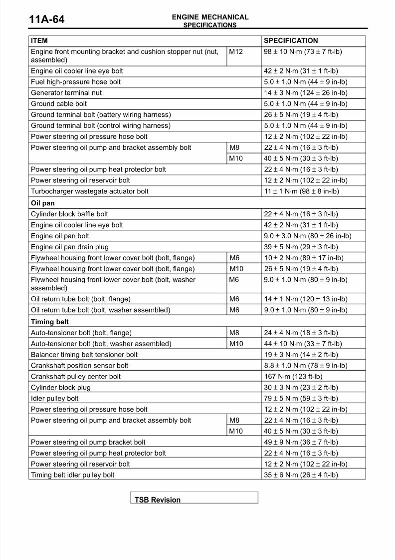
8/8/2019 GR00003800-11A
http://slidepdf.com/reader/full/gr00003800-11a 64/66
SPECIFICATIONS
TSB Revision
ENGINE MECHANICAL11A-64
Engine front mounting bracket and cushion stopper nut (nut,
assembled)
M12 98 ± 10 N⋅m (73 ± 7 ft-lb)
Engine oil cooler line eye bolt 42 ± 2 N⋅m (31 ± 1 ft-lb)
Fuel high-pressure hose bolt 5.0 ± 1.0 N⋅m (44 ± 9 in-lb)
Generator terminal nut 14 ± 3 N⋅m (124 ± 26 in-lb)
Ground cable bolt 5.0 ± 1.0 N⋅m (44 ± 9 in-lb)
Ground terminal bolt (battery wiring harness) 26 ± 5 N⋅m (19 ± 4 ft-lb)
Ground terminal bolt (control wiring harness) 5.0 ± 1.0 N⋅m (44 ± 9 in-lb)
Power steering oil pressure hose bolt 12 ± 2 N⋅m (102 ± 22 in-lb)
Power steering oil pump and bracket assembly bolt M8 22 ± 4 N⋅m (16 ± 3 ft-lb)
M10 40 ± 5 N⋅m (30 ± 3 ft-lb)
Power steering oil pump heat protector bolt 22 ± 4 N⋅m (16 ± 3 ft-lb)
Power steering oil reservoir bolt 12 ± 2 N⋅m (102 ± 22 in-lb)
Turbocharger wastegate actuator bolt 11 ± 1 N⋅m (98 ± 8 in-lb)
Oil pan
Cylinder block baffle bolt 22 ± 4 N⋅m (16 ± 3 ft-lb)
Engine oil cooler line eye bolt 42 ± 2 N⋅m (31 ± 1 ft-lb)
Engine oil pan bolt 9.0 ± 3.0 N⋅m (80 ± 26 in-lb)
Engine oil pan drain plug 39 ± 5 N⋅m (29 ± 3 ft-lb)
Flywheel housing front lower cover bolt (bolt, flange) M6 10 ± 2 N⋅m (89 ± 17 in-lb)
Flywheel housing front lower cover bolt (bolt, flange) M10 26 ± 5 N⋅m (19 ± 4 ft-lb)
Flywheel housing front lower cover bolt (bolt, washer
assembled)
M6 9.0 ± 1.0 N⋅m (80 ± 9 in-lb)
Oil return tube bolt (bolt, flange) M6 14 ± 1 N⋅m (120 ± 13 in-lb)
Oil return tube bolt (bolt, washer assembled) M6 9.0 ± 1.0 N⋅m (80 ± 9 in-lb)
Timing belt
Auto-tensioner bolt (bolt, flange) M8 24 ± 4 N⋅m (18 ± 3 ft-lb)
Auto-tensioner bolt (bolt, washer assembled) M10 44 ± 10 N⋅m (33 ± 7 ft-lb)
Balancer timing belt tensioner bolt 19 ± 3 N⋅m (14 ± 2 ft-lb)
Crankshaft position sensor bolt 8.8 ± 1.0 N⋅m (78 ± 9 in-lb)
Crankshaft pulley center bolt 167 N⋅m (123 ft-lb)
Cylinder block plug 30 ± 3 N⋅m (23 ± 2 ft-lb)
Idler pulley bolt 79 ± 5 N⋅m (59 ± 3 ft-lb)
Power steering oil pressure hose bolt 12 ± 2 N⋅m (102 ± 22 in-lb)
Power steering oil pump and bracket assembly bolt M8 22 ± 4 N⋅m (16 ± 3 ft-lb)
M10 40 ± 5 N⋅m (30 ± 3 ft-lb)
Power steering oil pump bracket bolt 49 ± 9 N⋅m (36 ± 7 ft-lb)
Power steering oil pump heat protector bolt 22 ± 4 N⋅m (16 ± 3 ft-lb)
Power steering oil reservoir bolt 12 ± 2 N⋅m (102 ± 22 in-lb)
Timing belt idler pulley bolt 35 ± 6 N⋅m (26 ± 4 ft-lb)
ITEM SPECIFICATION
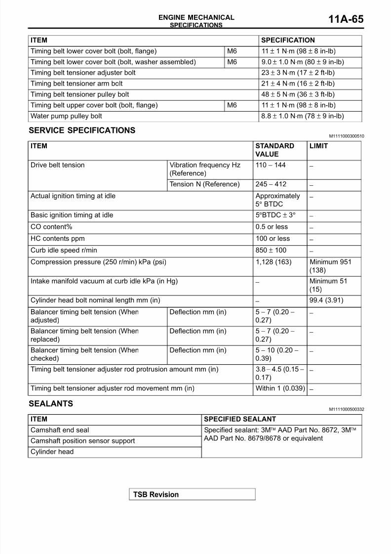
8/8/2019 GR00003800-11A
http://slidepdf.com/reader/full/gr00003800-11a 65/66
SPECIFICATIONS
TSB Revision
ENGINE MECHANICAL 11A-65
SERVICE SPECIFICATIONSM1111000300510
SEALANTSM1111000500332
Timing belt lower cover bolt (bolt, flange) M6 11 ± 1 N⋅m (98 ± 8 in-lb)
Timing belt lower cover bolt (bolt, washer assembled) M6 9.0 ± 1.0 N⋅m (80 ± 9 in-lb)
Timing belt tensioner adjuster bolt 23 ± 3 N⋅m (17 ± 2 ft-lb)
Timing belt tensioner arm bolt 21 ± 4 N⋅m (16 ± 2 ft-lb)
Timing belt tensioner pulley bolt 48 ± 5 N⋅m (36 ± 3 ft-lb)Timing belt upper cover bolt (bolt, flange) M6 11 ± 1 N⋅m (98 ± 8 in-lb)
Water pump pulley bolt 8.8 ± 1.0 N⋅m (78 ± 9 in-lb)
ITEM SPECIFICATION
ITEM STANDARD
VALUE
LIMIT
Drive belt tension Vibration frequency Hz
(Reference)
110 − 144 −
Tension N (Reference) 245 − 412 −
Actual ignition timing at idle Approximately5° BTDC
−
Basic ignition timing at idle 5°BTDC ± 3° −
CO content% 0.5 or less −
HC contents ppm 100 or less −
Curb idle speed r/min 850 ± 100 −
Compression pressure (250 r/min) kPa (psi) 1,128 (163) Minimum 951
(138)
Intake manifold vacuum at curb idle kPa (in Hg) − Minimum 51
(15)Cylinder head bolt nominal length mm (in) − 99.4 (3.91)
Balancer timing belt tension (When
adjusted)
Deflection mm (in) 5 − 7 (0.20 −
0.27)−
Balancer timing belt tension (When
replaced)
Deflection mm (in) 5 − 7 (0.20 −
0.27)−
Balancer timing belt tension (When
checked)
Deflection mm (in) 5 − 10 (0.20 −
0.39)−
Timing belt tensioner adjuster rod protrusion amount mm (in) 3.8 − 4.5 (0.15 −
0.17)−
Timing belt tensioner adjuster rod movement mm (in) Within 1 (0.039) −
ITEM SPECIFIED SEALANT
Camshaft end seal Specified sealant: 3Mä AAD Part No. 8672, 3Mä
AAD Part No. 8679/8678 or equivalentCamshaft position sensor support
Cylinder head
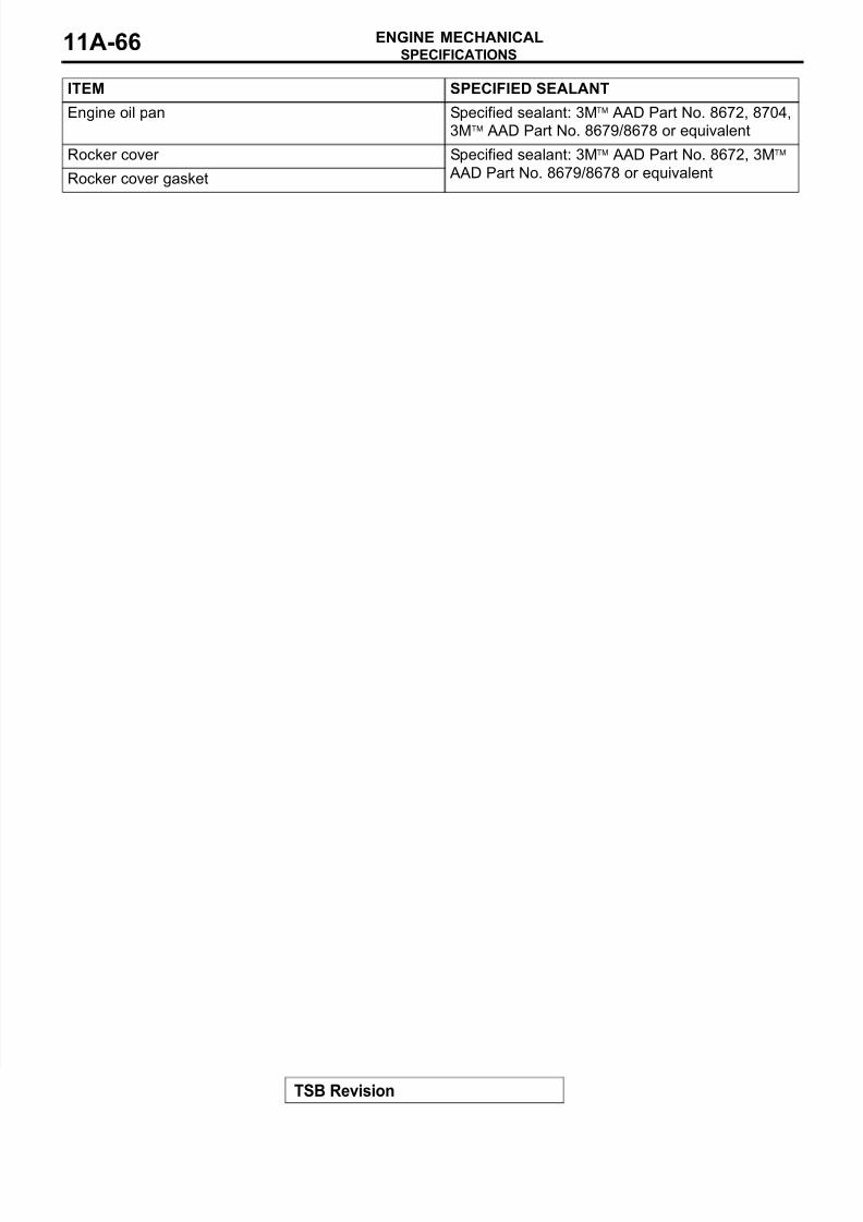
8/8/2019 GR00003800-11A
http://slidepdf.com/reader/full/gr00003800-11a 66/66
SPECIFICATIONS
ENGINE MECHANICAL11A-66
Engine oil pan Specified sealant: 3Mä AAD Part No. 8672, 8704,
3Mä AAD Part No. 8679/8678 or equivalent
Rocker cover Specified sealant: 3Mä AAD Part No. 8672, 3Mä
AAD Part No. 8679/8678 or equivalentRocker cover gasket
ITEM SPECIFIED SEALANT