GPS COMPLIANCE ASSESSMENT AND R2 MODEL VALIDATION … · gps compliance assessment and r2 model...
47
GPS COMPLIANCE ASSESSMENT AND R2 MODEL VALIDATION TEST PLAN TEMPLATE FOR POWER ELECTRONIC INTERFACED NON- SYNCHRONOUS GENERATION TECHNOLOGIES Published: September 2016
Transcript of GPS COMPLIANCE ASSESSMENT AND R2 MODEL VALIDATION … · gps compliance assessment and r2 model...

GPS COMPLIANCE ASSESSMENT AND R2 MODEL VALIDATION TEST PLAN TEMPLATE
FOR POWER ELECTRONIC INTERFACED NON-SYNCHRONOUS GENERATION TECHNOLOGIES
Published: September 2016

GPS COMPLIANCE ASSESSMENT AND R2 MODEL VALIDATION TEST PLAN TEMPLATE
© The material in this publication may be used in accordance with the copyright permissions on AEMO’s website.
Australian Energy Market Operator Ltd ABN 94 072 010 327 www.aemo.com.au [email protected]
NEW SOUTH WALES QUEENSLAND SOUTH AUSTRALIA VICTORIA AUSTRALIAN CAPITAL TERRITORY TASMANIA WESTERN AUSTRALIA
IMPORTANT NOTICE
Purpose
AEMO has prepared this document to provide information to assist Proponents in preparation of
commissioning and R2 model validation test plan for non-synchronous generation technologies such as
wind and solar, as at the date of publication.
Disclaimer
This document or the information in it may be subsequently updated or amended. This document does
not constitute legal or business advice, and should not be relied on as a substitute for obtaining detailed
advice about the National Electricity Law, the National Electricity Rules, or any other applicable laws,
procedures or policies. AEMO has made every effort to ensure the quality of the information in this
document but cannot guarantee its accuracy or completeness.
Accordingly, to the maximum extent permitted by law, AEMO and its officers, employees and
consultants involved in the preparation of this document:
make no representation or warranty, express or implied, as to the currency, accuracy, reliability or
completeness of the information in this document; and
are not liable (whether by reason of negligence or otherwise) for any statements or representations
in this document, or any omissions from it, or for any use or reliance on the information in it.

GPS COMPLIANCE ASSESSMENT AND R2 MODEL VALIDATION TEST PLAN TEMPLATE
© AEMO 2016 3
TABLE OF CONTENTS
IMPORTANT NOTICE 2
CHAPTER 1. INTRODUCTION 5
CHAPTER 2. GENERAL REQUIREMENTS 6
Pre-energisation requirements 6
Test schedule 6
Test plan 7
Hold Points 7
Measurement equipment 8
Test data file names 9
CHAPTER 3. TYPICAL TESTS FOR NON-SYNCHRONOUS GENERATION TECHNOLOGIES 11
Hold Point 1 Tests 11
3.1.1 Synchronous dynamic reactive support device (SDRD) control test – HP1_SDR test (if
applicable) 11
3.1.2 Non-synchronous dynamic reactive support device (NDRD) control system test – HP1
NDR test (if applicable) 11
3.1.3 Background power quality measurements (HP1_WFPQT/HP1_SFPQT) 15
3.1.4 Generating unit signal injection tests (HP1_WFSI/HP1_SFSI) 15
Hold Point 2 Tests 16
3.2.1 Power quality test (HP2_WFPQT/HP2_SFPQT) 16
3.2.2 Generating unit and park dispatch control test 16
3.2.3 Generating system reactive power capability test (HP2_WFRCT/HP2_SFRCT) 21
3.2.4 Static reactive support device manual switching test (HP2_WFCAP/HP2_SFCAP) 23
3.2.5 Generating system active power dispatch test (HP2_WFAPT/HP2_SFAPT) 25
3.2.6 Generating system reactive power dispatch test (HP2_WFRPT/HP2_SFRPT) 27
3.2.7 Generating system voltage reference step test (HP2_WFVCT/HP2_SFVCT) 29
3.2.8 Generating system power factor reference step test (HP2_WFPFT/HP2_SFPFT) (if
applicable) 31
3.2.9 Generating system transformer manual tap position change test
(HP2_WFTXT/HP2_SFTXT) 33
Hold Point 3 Test 35
3.3.1 Power quality test (HP3_WFPQT/HP3_SFPQT) 35
3.3.2 Generating system reactive power capability test (HP3_WFRCT/HP3_SFRCT) 35
3.3.3 Generating system active power dispatch test (HP3_WFAPT/HP3_SFAPT) 35
3.3.4 Generating system reactive power dispatch test (HP3_WFRPT/HP3_SFRPT) 35

GPS COMPLIANCE ASSESSMENT AND R2 MODEL VALIDATION TEST PLAN TEMPLATE
© AEMO 2016 4
3.3.5 Generating system voltage reference step test (HP3_WFVCT/HP3_SFVCT) 35
3.3.6 Generating system power factor reference step test (HP3_WFPFT/HP3_SFPFT) (if
applicable) 35
3.3.7 Generating system transformer manual tap position change test
(HP3_WFTXT/HP3_SFTXT) 35
Hold Point 4 Test 36
3.4.1 Power quality test HP4_WFPQT/HP4_SFPQT 36
3.4.2 Generating system reactive power capability test (HP4_WFRCT/HP4_SFRCT) 36
3.4.3 Static reactive support device manual switching test (HP4_WFCAP/HP4_SFCAP) 36
3.4.4 Generating system active power dispatch test (HP4_WFAPT/HP4_SFAPT) 36
3.4.5 Generating system reactive power dispatch test (HP4_WFRPT/HP4_SFRPT) 37
3.4.6 Generating system voltage reference step test (HP4_WFVCT/HP4_SFVCT) 37
3.4.7 Generating system power factor reference step test (HP4_WFPFT/HP4_SFPFT) (if
applicable) 37
3.4.8 Generating system transformer manual tap position change test
(HP4_WFTXT/HP4_SFTXT) 37
3.4.9 Generating system frequency control test HP4_WFFCT/HP4_SFFCT (if applicable) 37
3.4.10 Partial generating system trip test (HP4_PWFTT/HP4_PSFTT) 38
3.4.11 Other Hold Point 4 tests 40
3.4.12 System event analysis 40
APPENDIX A. 41
Main points of contact 41
Overview of GPS Compliance Assessment Tests 42
Test schedule example 43
Load profile example 45
Measurement point layout example 46
MEASURES AND ABBREVIATIONS 47
TABLE
Table 1: Typical signals to be measured for non-synchronous dynamic reactive support device control
system tests 14 Table 2: Typical signals to be measured for Generating unit and park dispatch control tests 20 Table 3: Key stakeholders from each party involved in commissioning and R2 tests 41 Table 5: Sample test schedule 43

GPS COMPLIANCE ASSESSMENT AND R2 MODEL VALIDATION TEST PLAN TEMPLATE
© AEMO 2016 5
CHAPTER 1. INTRODUCTION
This document has been prepared to guide Proponents preparing testing programs for power electronic
interfaced non-synchronous generation technologies as required by National Electricity Rules (NER)
clauses 5.8.4 and S5.2.4 (d). Tests required by these two clauses are often referred to as Generator
Performance Standard (GPS) compliance and R2 model validation tests.
This document also applies for preparing test plans in accordance with the rule clause 5.7.3 (tests to
demonstrate compliance with connection requirements for generators) and clause 5.7.6 (tests of
generating units requiring changes to normal operation). Proponents may also use this document for
developing a routine compliance test program as set out in rule 4.15 (b).
The objective of commissioning and GPS compliance testing program is to establish that the installed
plant performs as expected, and complies with the performance requirements set out in the GPS,
technical requirements specified in the connection agreement and in relevant Australian Standards.
Additionally, the Proponent is required to carry out tests to validate the R2 model and its parameters
and ensure that the plant models represent the installed system.
In general, there are some inter-relations between the tests required for GPS compliance assessment,
and R2 model and data validation. It is Proponent’s responsibility to consider whether to combine the
two test programs, or conduct each separately according to the NER timeframes.
This document is generic and can be applied to any tests carried out in relation to the above NER
clauses, including the following applications:
New and upgraded plant.
Non-synchronous generation technologies primarily based on wind and solar photovoltaic (PV).
Commissioning and compliance testing, and R2 model validation tests, and other tests carried out
under clauses 5.7.3, 5.7.6 or 4.15 (b). Example of such other tests include:
Temporary changes to control system settings.
Temporary changes to plant operating modes.
The document is not expected to cover every conceivable variation that may apply to the generating
system design. Minor modifications to the test template are therefore acceptable when submitting it to
AEMO and relevant Network Service Provider (NSP).
This document does not cover tests carried out due to changes in plant protection systems.
Additionally, it is not expected to serve as a detailed test procedure (also referred to as Inspection and
Test Procedure (ITP)) for test engineers for on-site testing.
This document is related to other policies, procedures and guidelines produced by AEMO and should
be read in conjunction with these, as follows:
Generating Systems Model Guidelines.
Generating Systems Design Datasheets and Settings Datasheets.
Commissioning Requirements for Generating Systems.
R2 Testing Guideline.
Data and Model Requirements for Generating Systems less than 30 MW.
GPS COMPLIANCE ASSESSMENT AND R2 MODEL VALIDATION TEST PLAN TEMPLATE
© AEMO 2016 6
CHAPTER 2. GENERAL REQUIREMENTS
Pre-energisation requirements The following information is required before compliance and/or R2 model validation testing begins.
Registered GPS.
Connection study report.
Registered Generating System Design Data Sheets and Generating System Setting Data Sheets
R1 model package:
Generating unit model and aggregation method used
Generating system central dispatch control model
Static and dynamic reactive support devices model (if applicable)
Coordinated generating system control system model (if applicable)
R1 block diagrams for the above models.
R1 model source code.
R1 model parameters.
Releasable user guide (RUG).
A commissioning program as per Rule 5.8.4, and as described in subsequent sections of this
document.
Pre-test simulation studies
This is particularly necessary when connecting non-synchronous energy sources to weak
networks to ensure that the extent of changes applied to reactive power and voltage at the
Point of Connection (PoC) would not adversely impact the area to which the generating system
is connected.
Generating system layout including location of the closest NSP sub-station, generating unit and
generating system transformers, transmission line/cable arrangement, other static and dynamic
reactive support devices (if available).
Type tests and off-site tests.
Test schedule
A test schedule includes all planned activities from the pre-energisation phase to returning the
machine(s) to commercial operation. Refer to Table 4 for a recommended template. The following
information is generally included:
Active and reactive power output expected for each test at each Hold Point.
A list of all GPS compliance assessment or R2 model validation tests conducted, including:
Off line tests.
On line tests for all Hold Points.
Load profiles for each day of testing are required to be submitted two business days before testing.
Refer to Figure 6 for preferred template. Ensure that all tests specified in the commissioning
schedule are accurately represented in the daily load profiles, if any inconsistency exists, it’s
expected that the registered participant will update these documents with the latest commissioning
information.

GPS COMPLIANCE ASSESSMENT AND R2 MODEL VALIDATION TEST PLAN TEMPLATE
© AEMO 2016 7
Test plan
The Proponent is expected to submit a test plan for approval from AEMO and the relevant NSP before
test commencement. Chapter 3 presents a list of typical tests and associated test procedures for
conventional synchronous machines.
Hold Points
When commissioning a new or upgraded plant (as defined under clause 5.3.9 of National Electricity
Rules) for the first time, or making a change to control system settings or mode of operation, a number
of Hold Points are generally required whereby the generating system overall output is constrained to a
pre-defined megawatt (MW) level. At each Hold Point, a report is required to be submitted to AEMO and
the relevant NSP for review and approval, before progressing further with the commissioning activities.
This process allows for staged release of capacity subject to:
Successful demonstration of applicable GPS clauses.
Confirmation of simulation model(s) against measured responses for all tests which can be
replicated by performing dynamic simulation.
The number of Hold Points could vary depending on the size of the generating system and its impact on
the interconnected power system.
Typical Hold Points, as shown in Figure 1 for illustrative purpose, include:
HP 1 – Prior to energisation of generating units (only applicable if the generating system’s balance
of plant comprises dynamic reactive support plant).
HP 2 – At least 20% of plant maximum output with 1/3 of individual generating units in service.
HP 3 – At least 50% of plant maximum output with 2/3 of individual generating units in service.
HP 4 – At least 80% of plant maximum output with all individual generating units in service.
Figure 1. Typical Hold Point regions and measurements

GPS COMPLIANCE ASSESSMENT AND R2 MODEL VALIDATION TEST PLAN TEMPLATE
© AEMO 2016 8
Information provided is based on the assumption that three Hold Points are required. In practice, AEMO
or the NSP can request more than three Hold Points based on the location and relative size of the
generating system.
Note that Hold Points defined above are based on active power output level assuming that measured
responses are stable, and that a reasonable correlation exists between measured and simulated
responses. Additional Hold Points may be introduced if either of the above criteria is not met during
Hold Point testing.
Measurement equipment
This section presents information that needs to be provided on the measurement equipment and its
location as follows:
Manufacturer, model and serial number of the equipment.
Type of equipment1:
Continuous monitoring, or event triggering, or manual triggering or others.
Measurement equipment should be permanent to allow for compliance with rule clauses 4.15(b)
and 5.7.3(g).
Location of measurement equipment:
Power electronic interfaced non-synchronous technologies such as wind and solar farms
generally consist of several generating units and reactive support devices. Measurement
equipment must therefore be provided at various locations within the generating system
including:
○ Point of common coupling (PoC) or high voltage terminals of plant transformers (T1 HV)
(See Figure 7).
○ MV collector bus to which the generating units are connected.
○ Generating units:
At least one for each different type of generating units; and the most common generating
unit type would need to have high-speed data recorders at both the electrically closest
and furthest generating units with respect to the MV collection grid.
As an example, a wind farm comprising (30) x 3 MW type 3 wind turbines, (15) x 3 MW
type 4 wind turbines, and (15) x 2 MW type 4 wind turbines would need to have two high-
speed data recorders for the 3 MW type 3 wind turbines, and one for each of the other
two types.
○ Some of the non-synchronous generation technologies may have generating units with
multiple LV terminals, e.g. some designs of doubly fed asynchronous generators have two
LV terminals. Measurement locations for such technologies are expected to cover both LV
terminals.
○ Each type of dynamic reactive support device, such as STATCOMs and synchronous
condensers (if applicable).
○ Central park level controller.
Sampling rate and time window available for configuration.
Non-synchronous generation technologies generally employ fast acting power electronic converter
controls. High speed measurement equipment is therefore required to capture the dynamic
response adequately. Typical sampling rate of such measurement equipment is over 10 kHz.
Format of measurement data (CSV or COMTRADE).
1 It is expected that independent equipment are installed to collect test results separate from the device under test.

GPS COMPLIANCE ASSESSMENT AND R2 MODEL VALIDATION TEST PLAN TEMPLATE
© AEMO 2016 9
The following data and information should be made available to AEMO and the relevant NSP:
All pre-processed measurement (raw) data.
○ A minimum resolution of 100 Hz for electrical quantities and 1 kHz for control signals is
required.
Scaling factors for all signals.
Information on post-processing of raw measurement data, such as re-sampling, filtering,
averaging and calculations of the signals.
Format of measurement data.
The following data and information needs to be made available to AEMO/NSP if requested.
All pre-processed measurement (raw) data.
Scaling factors for all signals.
Signals sampling rate.
Information on post-processing of raw measurement data, such as re-sampling, filtering,
averaging and calculations of signals.
Acceptance testing report for measurement equipment.
Valid and up-to-date calibration certificate of measurement equipment.
Signals to be measured at each measurement location.
Where multiple recorders are to be used, details on how measurement results will be
synchronised.
Generating units with high-speed measurement equipment must be in-service for all tests.
Measured voltages must be available in three-phase instantaneous waveforms, three-phase root
mean square (RMS), and positive-sequence RMS forms.
Test data file names
The following naming convention is sought for all test data files captured:
PlantName_SectionName_HPNo_TestName_TNo.CSV
PlantName_SectionName_ HPNo_ TestName_TNo. CSV
Abbreviated plant name
Section name
Hold Point number
Test name abbreviation
Test number i.e. 1, 2, 3 etc

GPS COMPLIANCE ASSESSMENT AND R2 MODEL VALIDATION TEST PLAN TEMPLATE
© AEMO 2016 10
For example,
Wind Farm X_South section_HP2_VSR_2_B.CSV
refers to a test carried out at Wind Farm X, South section, Hold Point 2, Voltage Step Response (VSR)
test, test number 2.
Note that for individual generator unit testing, “Section name” is replaced with “Unit number”.
GPS COMPLIANCE ASSESSMENT AND R2 MODEL VALIDATION TEST PLAN TEMPLATE
© AEMO 2016 11
CHAPTER 3. TYPICAL TESTS FOR NON-
SYNCHRONOUS GENERATION
TECHNOLOGIES
Typical tests for power electronic interfaced non-synchronous generation technologies, and the
information sought from proponents for each test, is highlighted below. Some aspects of the generating
system GPS and R2 models cannot be fully demonstrated/validated through staged tests. In these
circumstances the Generator is required to specify the alternative assessment methodology.
Hold Point 1 Tests
3.1.1 Synchronous dynamic reactive support device (SDRD) control test – HP1_SDR test (if applicable)
The operation of synchronous dynamic reactive support devices, commonly referred to as synchronous
condensers is identical to that of synchronous generators with an excitation system. Tests conducted
on a synchronous condenser are therefore similar to those applied for a synchronous generator, except
that a synchronous condenser is part of the overall generating system and does not have any direct
GPS compliance requirements. Further information on tests required for synchronous machines can be
found in AEMO’s GPS Compliance Assessment and R2 Model Validation Test Plan Template2.
3.1.2 Non-synchronous dynamic reactive support device (NDRD) control system test – HP1 NDR test (if applicable)
Purpose
To assess the response of voltage control system and step response characteristics of voltage and
reactive power
To validate the non-synchronous dynamic reactive support device control system model
parameters including:
Reactive power capability.
Control model parameters such as:
○ Control gains, time constants and limits.
[Note: The non-synchronous dynamic reactive support device control system model parameters listed
above are provided for illustrative purposes. The Generator is required to specify all model parameters
being validated].
Pre-test conditions
All generating units are offline.
Generating systems’ connection point is energised.
All other reactive support devices are offline.
Control system of non-synchronous dynamic support device is in-service and configured to default
control mode.
The generating system transformers are in manual control (fixed tap).
2 http://www.aemo.com.au/Electricity/Policies-and-Procedures/GPS-Compliance-Assessment-and-R2-Model-Validation-Test-Plan-Template
GPS COMPLIANCE ASSESSMENT AND R2 MODEL VALIDATION TEST PLAN TEMPLATE
© AEMO 2016 12
Reactive power capability test (HP1 NDR Test A)
Methodology and procedure
Pre-test simulation studies report is submitted by the Generator to verify the extent of changes in
network voltage and reactive power.
Pre-test conditions are confirmed.
Confirm the measurement systems are ready.
Configure the control system to reactive power control and set Qref to 0 MVAr.
Increase Qref to positive limit in steps (step size can be determined from pre-test simulation
studies and will be agreed NSP and AEMO. Typical sizes are 2 to 5 MVAR).
Return Qref to 0 MVAr in steps (2 to 5 MVAR step).
Decrease Qref to negative limit in steps (2 to 5 MVAR step).
Return Qref to 0 MVAr in steps (2 to 5 MVAR step).
Allow the device to run continuously for 10-15 minutes at each operating point above with at least
60 seconds recording time after the response has settled at its steady-state value.
View test data file to ensure it has been successfully saved.
Reconfigure the control system to default control mode.
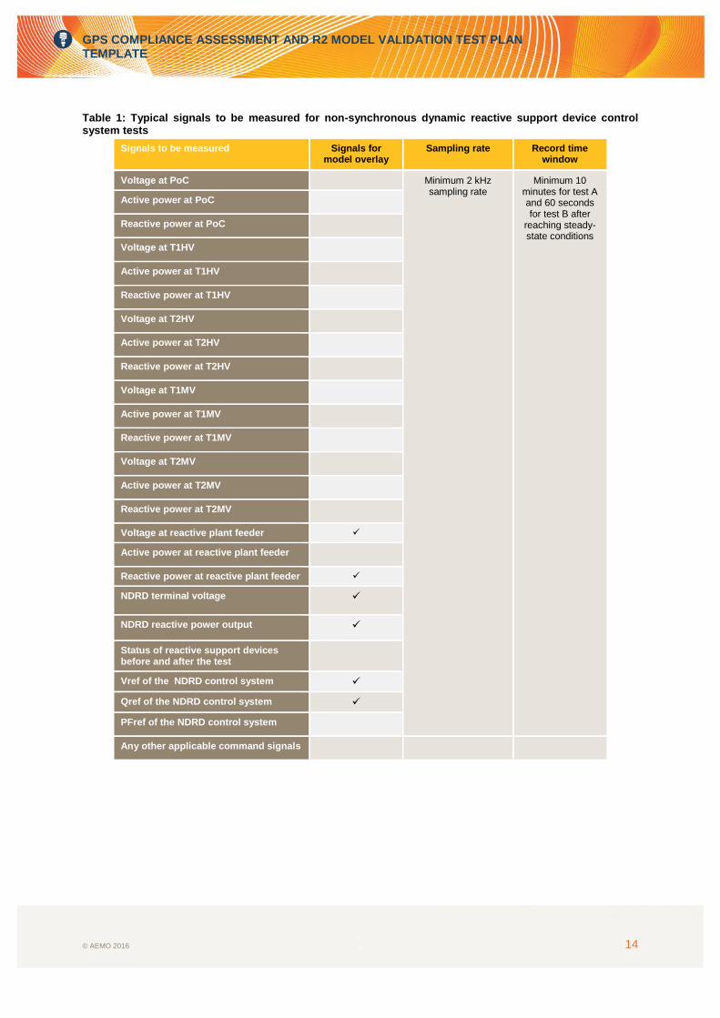
Signals to be measured
Table 1 shows the typical signals to be measured for the HP1_NDR Test A, and highlights those that
need to be compared against the respective simulated response.
Measurement data file name and format
PlantName_UnitNo_HP1_NDR_T01.CSV.
Acceptance criteria
Reactive power output follows the reference set-point correctly.
Reactive power limits demonstrated in the tests are consistent with those submitted as part of
AEMO’s Generating System Design and Setting Datasheets.
The device can generate maximum reactive power (capacitive and inductive) continuously.
Measurement data is successfully downloaded and confirmed.

GPS COMPLIANCE ASSESSMENT AND R2 MODEL VALIDATION TEST PLAN TEMPLATE
© AEMO 2016 13
Voltage control test (HP1 NDR Test B)
Methodology and procedure
Pre-test conditions are confirmed.
Confirm the measurement systems are ready.
Configure the control system to voltage control and set Vref to measured target voltage.
Increase Vref to Vref_max in steps (0.1 per unit (pu) step).
Return Vref to pre-test level in steps (0.1 pu step).
Decrease Vref to Vref_min in steps (0.1 pu step).
Return Vref to pre-test level steps (0.1 pu step).
Apply a +5% step to Vref.
Apply a -5% step to Vref.
Allow at least 10 seconds pre-triggered recording and at least 60 seconds recording time after the
response has settled at its steady-state value before the next test (step) commences.
View test data file to ensure it has been successfully saved.
Reconfigure the control system to default control mode.
Signals to be measured
Table 1 shows typical signals that need to be measured for the HP1_NDR Test B. Refer to Figure 7 for
location of measured signals.
Measurement data file name and format
PlantName_UnitNo_HP1_NDR_T02.CSV.
Acceptance criteria
Model overlays of the reactive power responses for the voltage step test are submitted as part of
Hold Point reports.
To assess conformance with AEMO’s Generating System Model Guidelines, +/- 10% accuracy
bands is superimposed on the graphs which include overlays of measured and simulated
responses.
Reactive power settling time for a 5% step response complies with the GPS clause S5.2.5.13, i.e.
a settling time of five seconds or less for the voltage step response.
Reactive power rise time for a 5% step response complies with the GPS clause S5.2.5.13, i.e. a
rise time of two seconds or less for the voltage step response.
Measurement data is successfully downloaded and confirmed.
GPS COMPLIANCE ASSESSMENT AND R2 MODEL VALIDATION TEST PLAN TEMPLATE
© AEMO 2016 14
Table 1: Typical signals to be measured for non-synchronous dynamic reactive support device control system tests
Signals to be measured Signals for model overlay
Sampling rate Record time window
Voltage at PoC Minimum 2 kHz sampling rate
Minimum 10 minutes for test A and 60 seconds for test B after
reaching steady-state conditions
Active power at PoC
Reactive power at PoC
Voltage at T1HV
Active power at T1HV
Reactive power at T1HV
Voltage at T2HV
Active power at T2HV
Reactive power at T2HV
Voltage at T1MV
Active power at T1MV
Reactive power at T1MV
Voltage at T2MV
Active power at T2MV
Reactive power at T2MV
Voltage at reactive plant feeder
Active power at reactive plant feeder
Reactive power at reactive plant feeder
NDRD terminal voltage
NDRD reactive power output
Status of reactive support devices before and after the test
Vref of the NDRD control system
Qref of the NDRD control system
PFref of the NDRD control system
Any other applicable command signals

GPS COMPLIANCE ASSESSMENT AND R2 MODEL VALIDATION TEST PLAN TEMPLATE
© AEMO 2016 15
3.1.3 Background power quality measurements (HP1_WFPQT/HP1_SFPQT)
Purpose
To determine background power quality signature at the connection point before connection of the
generating system.
Methodology and procedure
Background measurement (HP1_WFPQT/HP1_SFPQT)
It is generally expected that the background power quality data is available from the relevant NSP.
If the background power quality measurements are not available, a background power quality test
(HP1_WFPQT) at the PoC should be performed by the respective Generator before
commissioning begins. Steady-state continuous measurements must be conducted at the PoC for
at least one week and according to the method described in AS/NZS 61000.4.7:2012 and AS/NZS
61000.4.15:2012. These measurements must be conducted with all generating units and balance
of plant components disconnected.
3.1.4 Generating unit signal injection tests (HP1_WFSI/HP1_SFSI)
Purpose
To confirm voltage and frequency protection settings of the generating units consistent with GPS
clause S5.2.5.8.
To validate voltage and frequency protection settings implemented in dynamic models of
generating units.
Pre-test conditions
Confirm measurement systems are ready.
Methodology and procedure
Signal is injected to the generating units that are connected with measurement equipment. This is to
verify the generating unit protection settings, primarily the over- and under-voltage and frequency
protection settings.

GPS COMPLIANCE ASSESSMENT AND R2 MODEL VALIDATION TEST PLAN TEMPLATE
© AEMO 2016 16
Hold Point 2 Tests
3.2.1 Power quality test (HP2_WFPQT/HP2_SFPQT)
Purpose
To partially assess the following aspects of Generator Performance Standards:
S5.5.5.2 Quality of Electricity Generated.
S5.2.5.6 Quality of Electricity Generated and Continuous Uninterrupted Operation.
Methodology and procedure
Continuous measurement must be captured at the connection point (measurement window must be
agreed with the NSP and AEMO) as per the method described in AS/NZS 61000.4.7:2012 and AS/NZS
61000.4.15:2012. This is to ensure that the final power quality assessment based on IEC TR
61000.3.6:2012 and IEC TR 61000.3.7:2012 meets the agreed GPS limits.
Measurements include high (+80% of HP2 MW level) and low load conditions where practically
possible. The final compliance assessment of performance standards S5.5.5.2 on Quality of Electricity
Generated and S5.2.5.6 on Quality of Electricity Generated and Continuous Uninterrupted Operation
will be conducted by comparing results obtained from the background measurements before and after
connection of the generating system. Measurements used in the final report should include one week of
continuous measurements for each pre- and post-connection of the generating system.
3.2.2 Generating unit and park dispatch control test
Purpose
To validate reactive power capability of the generating units.
To validate generating unit model parameters related to reactive power limits.
Reactive power capability test (HP2 WTG Test A/ HP2 SI Test A)
Pre-test conditions
Generating units under test are operated with the park dispatch control enabled.
The park dispatch controller is under active and reactive power control mode.
All reactive support and energy storage devices are off line.
The generating system transformers are in manual control (fixed tap).
Methodology and procedure
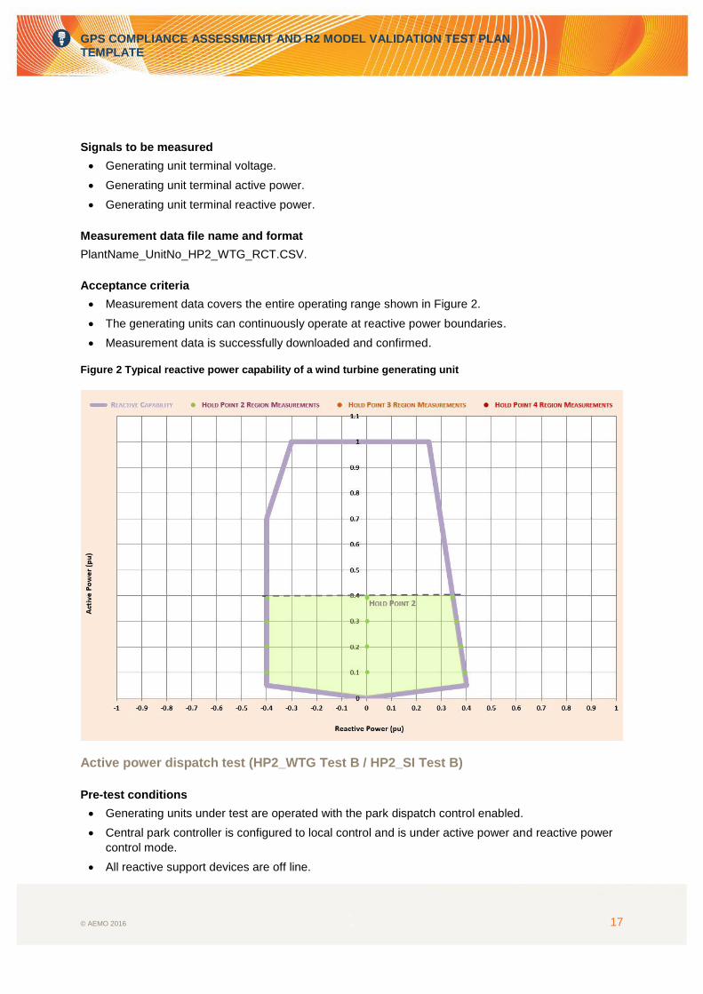
Generating units are operated at a wide range of operating conditions including output active
power of at least 80% of plant maximum output for the given HP, and boundaries of reactive power
generation and absorption. Figure 2 shows a typical reactive power capability of non-synchronous
generating unit with minimum operating points required to be captured during the test.
Measurement is required for at least two individual generating units for each different type of
generating unit installed.
View test data file to ensure it has been successfully saved.
GPS COMPLIANCE ASSESSMENT AND R2 MODEL VALIDATION TEST PLAN TEMPLATE
© AEMO 2016 17
Signals to be measured
Generating unit terminal voltage.
Generating unit terminal active power.
Generating unit terminal reactive power.
Measurement data file name and format
PlantName_UnitNo_HP2_WTG_RCT.CSV.
Acceptance criteria
Measurement data covers the entire operating range shown in Figure 2.
The generating units can continuously operate at reactive power boundaries.
Measurement data is successfully downloaded and confirmed.
Figure 2 Typical reactive power capability of a wind turbine generating unit
Active power dispatch test (HP2_WTG Test B / HP2_SI Test B)
Pre-test conditions
Generating units under test are operated with the park dispatch control enabled.
Central park controller is configured to local control and is under active power and reactive power
control mode.
All reactive support devices are off line.

GPS COMPLIANCE ASSESSMENT AND R2 MODEL VALIDATION TEST PLAN TEMPLATE
© AEMO 2016 18
The generating system transformers are in manual control (fixed tap).
The generating units are operating at above 80% of rated active power output.
Methodology and procedure
Pre-test conditions are confirmed.
Confirm the measurement system is ready.
Apply a -20% step to the active power dispatch set point (Pdsp).
Allow at least 10 seconds pre-triggered recording and at least 60 seconds recording time after the
response has settled at its steady-state value before the next test (step) commences.
Return Pdsp to the pre-test value.
Wait until the response settles.
Confirm the generating units are still generating over 80% of rated output.
Repeat the test with a -50% step.
View test data file to ensure it has been successfully saved.
Signals to be measured
Table 2 summarises typical signals to be measured for the generating unit active power dispatch test,
and highlights those that need to be compared against the respective simulated response.
Measurement data file name and format
PlantName_UnitNo_HP2_WTG_APT.CSV.
Acceptance criteria
The active power response follows the reference correctly.
Model overlays for the active power dispatch test are submitted as part of Hold Point reports.
To assess conformance with AEMO’s Generating System Model Guidelines, +/- 10% accuracy
bands need to be superimposed on the graphs which include overlays of measured and simulated
responses.
Measurement data is successfully downloaded and confirmed.
Reactive power dispatch test (HP2 WTG Test C / HP2 SI Test C)
Pre-test conditions
Generating units under test are operated with the park dispatch control enabled.
Central park controller is configured to local control and is under active power and reactive power
control mode.
All reactive support devices are off line.
Generating system transformers are in manual control (fixed tap).
enerating units are operating at above 80% of rated active power output.
Methodology and procedure
Pre-test conditions are confirmed.
Confirm the measurement systems are ready.
The reactive dispatch (Qdsp) is set to 0 MVAr, i.e. the generating unit generates 0 MVAr at its
terminals.

GPS COMPLIANCE ASSESSMENT AND R2 MODEL VALIDATION TEST PLAN TEMPLATE
© AEMO 2016 19
Apply a small positive reactive power step to the reactive power dispatch set point Qdsp (typically
25%).
Wait until the response settles.
Allow at least 10 seconds pre-triggered recording and at least 60 seconds recording time after the
response has settled at its steady-state value before the next test (step) commences.
Return the Qdsp to 0 MVAr.
Wait until the response settles.
Allow at least 10 seconds pre-triggered recording and at least 60 seconds recording time after the
response has settled at its steady-state value before the next test (step) commences.
Confirm the generating units are still above 80% of rated output.
Repeat the test with a -25% step, +/-50% steps and +/-75% steps.
View test data file to ensure it has been successfully saved.
Signals to be measured
Table 2 summarises typical signals to be measured for the generating unit reactive power dispatch test,
and highlights those signals that need to be compared against the respective simulated response.
Measurement data file name and format
PlantName_UnitNo_HP2_WTG_RPT.CSV.
Acceptance criteria
The reactive power response follows the reference correctly.
Model overlays for the reactive power dispatch test are submitted as part of Hold Point reports.
To assess conformance with AEMO’s Generating System Model Guidelines, +/- 10% accuracy
bands need to be superimposed on the graphs which include overlays of measured and simulated
responses.
Measurement data is successfully downloaded and confirmed.

GPS COMPLIANCE ASSESSMENT AND R2 MODEL VALIDATION TEST PLAN TEMPLATE
© AEMO 2016 20
Table 2: Typical signals to be measured for Generating unit and park dispatch control tests
Signals to be measured Signals for model overlay
Sampling rate Record time window
Voltage at PoC Min. sampling rate of 100 Hz
for steady state tests and
2 kHz for dynamic tests
Allow at least 10 seconds pre-
triggered recording and at least 60
seconds recording time after the response has settled at its
steady-state value
Active power at PoC
Reactive power at PoC
Voltage at T1HV
Active power at T1HV
Reactive power at T1HV
Voltage at T2HV
Active power at T2HV
Reactive power at T2HV
Voltage at the central park level controller (if at a different location to above locations)
Active power at the central park level controller (if at a different location to above locations)
Reactive power at the central park level controller (if at a different location to above locations)
Voltage at T1MV
Active power at T1MV
Reactive power at T1MV
Voltage at T2MV
Active power at T2MV
Reactive power at T2MV
Terminal voltage of all generating units with high-speed data recorders
Active power of all generating units with high-speed data recorders
Reactive power of all generating units with high-speed data recorders
Active current of all generating units with high-speed data recorders
Reactive current of all generating units with high-speed data recorders
Wind speed variations
Solar irradiance variations
Status of reactive support plant before and after test
Status of all generating units (on-line, trip, pause) before and after the test
Voltage reference
Active power dispatch reference
Reactive power dispatch reference
Power factor set point reference
Frequency control set point reference
Any other applicable command signal

GPS COMPLIANCE ASSESSMENT AND R2 MODEL VALIDATION TEST PLAN TEMPLATE
© AEMO 2016 21
3.2.3 Generating system reactive power capability test (HP2_WFRCT/HP2_SFRCT)
Purpose
To assess compliance with GPS clause S5.2.5.1 with respect to reactive power capability of the
generating system.
To assess compliance with GPS clause S5.2.6.1 and rule clause 4.11.1 with respect to:
Confirmation of SCADA feedback signals.
Confirmation of communication equipment.
Pre-test conditions
The maximum generating system output is at the agreed HP2 MW level.
The total output of the generating units is above 80% of HP2 MW level.
The generating units are under park dispatch control.
The generating system is under default control mode, e.g. voltage control mode.
The dynamic and static reactive support plant are in service (if applicable).
The generating system transformers are under auto control.
Methodology and procedure
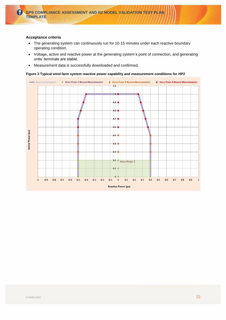
The generating system is operated at a wide range of operating conditions including reactive power
generation and absorption boundaries. Figure 3 shows a typical reactive power capability of non-
synchronous generating unit with minimum operating points that are required to be captured during HP2
test.
Pre-test simulation studies report is submitted by the Generator to verify the extent of changes in
network voltage and reactive power at the PoC which would not adversely impact the area to
which the generating system is connected.
Configure the generating system control to local control mode.
Configure the generating system control mode to reactive power control.
Confirm the measurement systems are ready.
Load the generating system to the operating condition specified in Figure 3.
Wait until the response settles.
Allow the generating units to run for 10-15 minutes at each operating point.
While the generating system is continuously running, view test data file to ensure it has been
successfully saved before moving to the next operating condition.
Signals to be measured
Table 2 summarises typical signals to be measured for the test, and highlights those signals that need
to be compared against the respective simulated response.
Measurement data file name and format
PlantName_SectionNo_HP2_WFRCT.CSV
GPS COMPLIANCE ASSESSMENT AND R2 MODEL VALIDATION TEST PLAN TEMPLATE
© AEMO 2016 22
Acceptance criteria
The generating system can continuously run for 10-15 minutes under each reactive boundary
operating condition.
Voltage, active and reactive power at the generating system’s point of connection, and generating
units’ terminals are stable.
Measurement data is successfully downloaded and confirmed.
Figure 3 Typical wind farm system reactive power capability and measurement conditions for HP2

GPS COMPLIANCE ASSESSMENT AND R2 MODEL VALIDATION TEST PLAN TEMPLATE
© AEMO 2016 23
3.2.4 Static reactive support device manual switching test3 (HP2_WFCAP/HP2_SFCAP)
Purpose
To assess compliance with GPS clause S5.2.5.13 with respect to voltage and reactive power
control of the generating system.
To assess response of coordinated voltage control strategy of the generating system and validate
associated simulation models, i.e. between the dynamic reactive support devices and generating
units (if applicable).
To validate the dynamic reactive support control system model and parameters (if applicable).
To validate the park dispatch control model and parameters.
To assess compliance with GPS clause S5.2.6.1 and rule clause 4.11.1 with respect to:
Confirmation of SCADA feedback signals.
Confirmation of communication equipment.
Pre-test conditions
Maximum generating system output is at the agreed HP2 MW level.
Total output of the generating units is above 80%4 of HP2 MW level.
Generating units are under park dispatch control.
The generating system is under default control mode, e.g. voltage control mode:
The dynamic reactive support control system is in-service.
The static reactive support devices are in service but in local manual control.
The generating system transformer is under auto control.
Methodology and procedure
Pre-test simulation studies report are submitted by the Generator to verify the extent of changes in
network voltage and reactive power at the PoC which would not adversely impact the area to
which the generating system is connected.
Configure the generating system control to local control mode.
Confirm the measurement systems are ready.
Switch-in a static reactive support device, such as a capacitor bank.
Wait until the response settles.
Switch-in another static reactive support device (if available).
Wait until the response settles.
Switch-off the static reactive support device that switched in first.
Wait until the response settles.
Switch-off another static reactive support device (if available).
Wait until the response settles.
Allow at least 10 seconds pre-triggered recording and at least 60 seconds recording time after the
response has settled at its steady-state value before the next test (step) commences.
View test data file to ensure it has been successfully saved.
3 Alternatively, this test may be conducted at other Hold Points. 4 Specific minimum generation level at each hold point must be agreed with AEMO and NSP.

GPS COMPLIANCE ASSESSMENT AND R2 MODEL VALIDATION TEST PLAN TEMPLATE
© AEMO 2016 24
Signals to be measured
Table 2 summarises typical signals that need to be measured for the test, and highlights those that
need to be compared against the respective simulated response.
Measurement data file name and format
PlantName_SectionNo_HP2_WFCAP.CSV.
Acceptance criteria
Model overlays for the static reactive support device manual switching test are submitted as part of
Hold Point reports.
To assess conformance with AEMO’s Generating System Model Guidelines, +/- 10% accuracy
bands need to be superimposed on the graphs which include overlays of measured and simulated
responses.
Generating is able to return to stable operation after each switching action.
The settling time of voltage response for the switching action complies with the specified
requirements of the GPS clause S5.2.5.13, e.g. 5 seconds settling required for a 5% voltage
disturbance.
The settling time of reactive power response for the switching action complies with the specified
requirements of the GPS clause S5.2.5.13, e.g. 5 seconds settling required for a 5% voltage
disturbance.
Measurement data is successfully downloaded and confirmed.

GPS COMPLIANCE ASSESSMENT AND R2 MODEL VALIDATION TEST PLAN TEMPLATE
© AEMO 2016 25
3.2.5 Generating system active power dispatch test (HP2_WFAPT/HP2_SFAPT)
Purpose
To assess compliance with GPS clause S5.2.5.14 with respect to active power control of the
generating system.
To confirm the active power dispatch command from AEMO control room and the generating
system local control.
To validate active power control loop model and parameters of the generating units.
To validate the park dispatch control model and parameters.
To assess compliance with GPS clause S5.2.6.1 and rule clause 4.11.1 with respect to:
Confirmation of SCADA feedback signals.
Confirmation of communication equipment.
Pre-test conditions
Maximum generating system output is at the agreed HP2 MW level.
Total output of the generating units is above 80%5 of HP2 MW level.
Generating units are under park dispatch control.
The generating system is under default control mode, e.g. voltage control mode.
The dynamic reactive support control system is in-service.
The static reactive support devices are in service and in auto control (if applicable).
The generating system transformer is under auto control.
Methodology and procedure6
This test is generally conducted in two stages and carried out in HP2/HP3 and HP4, respectively.
The first stage of the test involves active power dispatch test initiated through local generating system
SCADA control (HP2_WFAPT_LOC/HP2_SFAPT_LOC), and conducted as follows:
Configure the generating system control to local control mode.
Confirm the measurement systems are ready.
Apply a -20% step (20% of HP2 output level) to the Pdsp of the park dispatch controller.
Wait until the response settles.
Allow at least 10 seconds pre-triggered recording and at least 60 seconds recording time after the
response has settled at its steady-state value before the next test (step) commences.
Return the Pdsp to pre-test level.
Wait until the response settles.
Allow at least 10 seconds pre-triggered recording and at least 60 seconds recording time after the
response has settled at its steady-state value before the next test (step) commences.
Confirm the generating system output is above 80% of HP2 MW level.
Repeat the test with -50% and -80% steps.
View test data file to ensure it has been successfully saved.
The second stage of the test will be described in 3.4.4.
5 Specific minimum generation level at each hold point must be agreed with AEMO and NSP. 6 For generating systems with fast and slow ramp options, testing should be conducted with both ramp rates.

GPS COMPLIANCE ASSESSMENT AND R2 MODEL VALIDATION TEST PLAN TEMPLATE
© AEMO 2016 26
Signals to be measured
Table 2 summarises typical signals that that need to be measured for the test, and highlights those that
need to be compared against the respective simulated response.
Measurement data file name and format
PlantName_SectionNo_HP2_WFAPT_LOC.CSV.
Acceptance criteria
Model overlays of the Generating system active power dispatch test are submitted as part of Hold
Point reports.
To assess conformance with AEMO’s Generating System Model Guidelines, +/- 10% accuracy
bands need to be superimposed on the graphs which include overlays of measured and simulated
responses.
The generating system is able to return to stable operation after each step.
The response time of active power dispatch complies with the specified requirements of the GPS
clause S5.2.5.14, e.g. active power dispatch active completed within five minutes.
Measurement data is successfully downloaded and confirmed.

GPS COMPLIANCE ASSESSMENT AND R2 MODEL VALIDATION TEST PLAN TEMPLATE
© AEMO 2016 27
3.2.6 Generating system reactive power dispatch test (HP2_WFRPT/HP2_SFRPT)
Purpose
To assess compliance with GPS clause S5.2.5.13 with respect to voltage and reactive power
control of the generating system.
To validate reactive power control loop model and parameters of the generating units.
To validate the park dispatch control model and parameters.
To assess compliance with GPS clause S5.2.6.1 and rule clause 4.11.1 with respect to:
Confirmation of SCADA feedback signals.
Confirmation of communication equipment.
Pre-test conditions
Maximum generating system output is the agreed HP2 MW level.
Total output of the generating units is above 80%7 of HP2 MW level.
Generating units are under park dispatch control in active and reactive dispatch control mode.
All reactive support plant are off-line.
The generating system transformer is under auto control.
Methodology and procedure
Pre-test simulation studies report is submitted by the Generator to verify that the extent of changes
in network voltage and reactive power at the PoC would not adversely impact the area to which the
generating system is connected.
Pre-test conditions are confirmed.
Confirm the measurement systems are ready.
The reactive dispatch (Qdsp) is set to 0 MVAr, i.e. the generating unit generates 0 MVAr at its
terminals.
Apply a small positive reactive power step to the reactive power dispatch set point Qdsp
Typically 25% of possible reactive power available.
Wait until the response settles.
Allow at least 10 seconds pre-triggered recording and at least 60 seconds recording time after the
response has settled at its steady-state value before the next test (step) commences.
Return the Qdsp to 0 MVAr.
Wait until the response settles.
Allow at least 10 seconds pre-triggered recording and at least 60 seconds recording time after the
response has settled at its steady-state value before the next test (step) commences.
Confirm the generating units are still above 60% of rated output.
Repeat the test with a -25% step, +/-50% steps and +/-75% steps.
View test data file to ensure it has been successfully saved.
Signals to be measured
Table 2 summarises typical signals to be measured for the test.
7 Specific minimum generation level at each hold point must be agreed with AEMO and NSP.

GPS COMPLIANCE ASSESSMENT AND R2 MODEL VALIDATION TEST PLAN TEMPLATE
© AEMO 2016 28
Measurement data file name and format
PlantName_SectionNo_HP2_WFRPT.CSV
Acceptance criteria
The reactive power response follows the reference correctly.
Model overlays of generating system reactive power dispatch test are submitted as part of Hold
Point reports.
To assess conformance with AEMO’s Generating System Model Guidelines, +/- 10% accuracy
bands need to be superimposed on the graphs which include overlays of measured and simulated
responses.
Measurement data is successfully downloaded and confirmed.

GPS COMPLIANCE ASSESSMENT AND R2 MODEL VALIDATION TEST PLAN TEMPLATE
© AEMO 2016 29
3.2.7 Generating system voltage reference step test (HP2_WFVCT/HP2_SFVCT)
Purpose
To assess compliance with GPS clause S5.2.5.13 with respect to voltage control capability.
To assess response of coordinated voltage control strategy of the generating system and validate
associated simulation models (if applicable).
To validate static and dynamic reactive support control system model and parameters (if
applicable).
To validate the park dispatch voltage control model and parameters.
To assess compliance with GPS clause S5.2.6.1 and rule clause 4.11.1 with respect to:
Confirmation of SCADA feedback signals.
Confirmation of communication equipment.
Pre-test conditions
Maximum generating system output is at the agreed HP2 MW level.
Total output of the generating units is above 80%8 of HP2 MW level.
Generating units are under park dispatch control.
The generating system is under voltage control mode.
The generating system transformer is under auto control.
Methodology and procedure
Pre-test simulation studies report is submitted by the Generator to verify that the extent of changes
in network voltage and reactive power at the PoC would not adversely impact the area to which the
generating system is connected.
Configure the generating system control to local control mode.
Apply a +/-3% step to Vref.
Apply a -/+3% step to Vref.
Apply a +/-5% step to Vref.
Apply a -/+5% step to Vref.
Allow at least 10 seconds pre-triggered recording and at least 60 seconds recording time after the
response has settled at its steady-state value before the next test (step) commences.
View test data file to ensure it has been successfully saved.
Signals to be measured
Table 2 summarises typical signals to be measured for the test.
Measurement data file name and format
PlantName_SectionNo_HP2_WFVCT.CSV.
Acceptance criteria
Model overlays of the generating system voltage reference step test are submitted as part of Hold
Point reports. The following responses needs to be included:
Point of connection.
8 Specific minimum generation level at each hold point must be agreed with AEMO and NSP.
GPS COMPLIANCE ASSESSMENT AND R2 MODEL VALIDATION TEST PLAN TEMPLATE
© AEMO 2016 30
Static and dynamic reactive support plant.
Central park level controller.
Coordinated voltage control scheme.
To assess conformance with AEMO’s Generating System Model Guidelines, +/- 10% accuracy
bands need to be superimposed on the graphs which include overlays of measured and simulated
responses.
The generating system is able to return to stable operation after each step.
The settling time of voltage response for the switching action complies with the specified
requirements of the GPS clause S5.2.5.13, e.g. five seconds settling required for a 5% voltage
disturbance.
The settling time of reactive power response for the switching action complies with the specified
requirements of the GPS clause S5.2.5.13, e.g. five seconds settling required for a 5% voltage
disturbance.
Measurement data is successfully downloaded and confirmed.

GPS COMPLIANCE ASSESSMENT AND R2 MODEL VALIDATION TEST PLAN TEMPLATE
© AEMO 2016 31
3.2.8 Generating system power factor reference step test (HP2_WFPFT/HP2_SFPFT) (if applicable)
Purpose
To assess compliance with GPS clause S5.2.5.13 with respect to power factor control capability.
To assess response of coordinated power factor control strategy of the generating system and
validate associated simulation models (if applicable).
To validate static and dynamic reactive support control system model and parameters (if
applicable).
To validate the park dispatch power factor control model and parameters.
To assess compliance with GPS clause S5.2.6.1 and rule clause 4.11.1 with respect to:
Confirmation of SCADA feedback signals.
Confirmation of communication equipment.
Pre-test conditions
Maximum generating system output is at the agreed HP2 MW level.
Total output of the generating units is above 80%9 of HP2 MW level.
Generating units are under park dispatch control.
The generating system is under power factor control mode and the power factor reference (PFref)
is set to unity.
The generating system transformer is under auto control.
Methodology and procedure
Pre-test simulation studies report is submitted by the Generator to verify the extent of changes in
network voltage and reactive power at the PoC which would not adversely impact the area to
which the generating system is connected.
Configure the generating system control to local control mode.
Set PFref to 0.99 capacitive.
Set PFref back to unity.
Set PFref to 0.99 inductive.
Set PFref back to unity.
Set PFref to 0.95 (or plant GPS limit) capacitive.
Set PFref back to unity.
Set PFref to 0.95 (or plant GPS limit) inductive.
Set PFref back to unity.
Allow at least 10 seconds pre-triggered recording and at least 60 seconds recording time after the
response has settled at its steady-state value before the next test (step) commences.
View test data file to ensure it has been successfully saved.
Signals to be measured
Table 2 summarises typical signals to be measured for the test, and highlights those signals that need
to be compared against the respective simulated response.
9 Specific minimum generation level at each hold point must be agreed with AEMO and NSP.

GPS COMPLIANCE ASSESSMENT AND R2 MODEL VALIDATION TEST PLAN TEMPLATE
© AEMO 2016 32
Measurement data file name and format
PlantName_SectionNo_HP2_WFPFT.CSV
Acceptance criteria
Model overlays of the generating system voltage reference step test are submitted as part of Hold
Point reports. The following responses needs to be included:
Point of connection.
Static and dynamic reactive support plant.
Central park level controller.
Coordinated voltage control scheme.
To assess conformance with AEMO’s Generating System Model Guidelines, +/- 10% accuracy
bands need to be superimposed on the graphs which include overlays of measured and simulated
responses.
The generating system is able to return to stable operation after each step.
Measurement data is successfully downloaded and confirmed.

GPS COMPLIANCE ASSESSMENT AND R2 MODEL VALIDATION TEST PLAN TEMPLATE
© AEMO 2016 33
3.2.9 Generating system transformer manual tap position change test (HP2_WFTXT/HP2_SFTXT)
Purpose
To assess compliance with GPS clauses S5.2.5.4 and S5.2.5.13.
To assess response of the generating system and generating units to small voltage disturbances
caused by transformer tap changes.
To validate dynamic model and parameters of the generating units.
To validate dynamic model and parameters of the transformer tap changer (if applicable).
To validate dynamic model and parameters of the central park level controller.
To validate dynamic model and parameters of the overall generating system control system.
To validate dynamic model and parameters of the coordinated voltage control scheme (if
applicable).
To assess compliance with GPS clause S5.2.6.1 and rule clause 4.11.1 with respect to:
Confirmation of SCADA feedback signals.
Confirmation of communication equipment.
Pre-test conditions
Maximum generating system output is at the agreed HP2 MW level.
Total output of the generating units is above 80%10 of HP2 MW level.
Generating units are under park dispatch control.
The generating system is under default control mode, e.g. voltage control mode.
The generating system transformer is under manual control (fixed tap).
Methodology and procedure
Pre-test simulation studies report is submitted by the Generator to verify the extent of changes in
network voltage and reactive power at the PoC which would not adversely impact the area to
which the generating system is connected.
Configure the generating system control to local control mode.
Pre-test conditions are confirmed.
Vary generating system’s transformer tap position with the range identified from the pre-test
simulation with one (1) tap position at each step.
Monitor closely the voltage at the PoC, MV collection grid, and LV terminals of generating units
and reactive support devices to make sure that all voltages are within +/-10% of nominal all the
time.
Allow at least 60 seconds recording time after the response settled at steady state before the next
test (step) commences.
View test data file to ensure it has been successfully saved.
Signals to be measured
Table 2 summarises typical signals to be measured for the test, and highlights those signals that need
to be compared against the respective simulated response.
10 Specific minimum generation level at each hold point must be agreed with AEMO and NSP.

GPS COMPLIANCE ASSESSMENT AND R2 MODEL VALIDATION TEST PLAN TEMPLATE
© AEMO 2016 34
Measurement data file name and format
PlantName_SectionNo_HP2_WFTXT.CSV
Acceptance criteria
Model overlays of the generating system transformer manual tap position change test are
submitted as part of Hold Point reports. The following responses needs to be included:
Point of connection.
Static and dynamic reactive support plant.
Central park level controller.
Coordinated voltage control scheme.
To assess conformance with AEMO’s Generating System Model Guidelines, +/- 10% accuracy
bands need to be superimposed on the graphs which include overlays of measured and simulated
responses.
The generating system is able to return to stable operation after each step.
Measurement data is successfully downloaded and confirmed.

GPS COMPLIANCE ASSESSMENT AND R2 MODEL VALIDATION TEST PLAN TEMPLATE
© AEMO 2016 35
Hold Point 3 Test
3.3.1 Power quality test (HP3_WFPQT/HP3_SFPQT)
Refer to section 3.2.1 for specifics; the same methodology is to be used as applied for Hold Point 2.
3.3.2 Generating system reactive power capability test (HP3_WFRCT/HP3_SFRCT)
Refer to section 3.2.3 for specifics; the same methodology is to be used as applied for Hold Point 2.
Minimum test points are schematically shown in Figure 4.
Figure 4. Typical wind farm system reactive power capability and measurement conditions for hold point 2
3.3.3 Generating system active power dispatch test (HP3_WFAPT/HP3_SFAPT)
Refer to section 3.2.5 for specifics; the same methodology is to be used as applied for Hold Point 2.
3.3.4 Generating system reactive power dispatch test (HP3_WFRPT/HP3_SFRPT)
Refer to section 3.2.6 for specifics; the same methodology is to be used as applied for Hold Point 2.
3.3.5 Generating system voltage reference step test (HP3_WFVCT/HP3_SFVCT)
Refer to section 3.2.7 for specifics; the same methodology is to be used as applied for Hold Point 2.
3.3.6 Generating system power factor reference step test (HP3_WFPFT/HP3_SFPFT) (if applicable)
Refer to section 3.2.8 for specifics; the same methodology is to be used as applied for Hold Point 2.
3.3.7 Generating system transformer manual tap position change test (HP3_WFTXT/HP3_SFTXT)
Refer to section 3.2.9 for specifics; the same methodology is to be used as applied for Hold Point 2.
GPS COMPLIANCE ASSESSMENT AND R2 MODEL VALIDATION TEST PLAN TEMPLATE
© AEMO 2016 36
Hold Point 4 Test
3.4.1 Power quality test HP4_WFPQT/HP4_SFPQT
Refer to section 3.2.1 for specifics; the same methodology is to be used as applied for Hold Point 2.
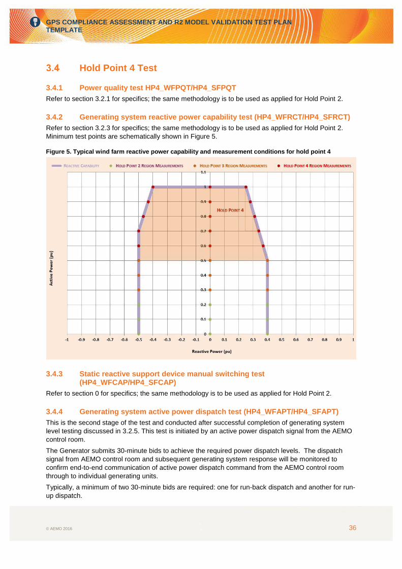
3.4.2 Generating system reactive power capability test (HP4_WFRCT/HP4_SFRCT)
Refer to section 3.2.3 for specifics; the same methodology is to be used as applied for Hold Point 2.
Minimum test points are schematically shown in Figure 5.
Figure 5. Typical wind farm reactive power capability and measurement conditions for hold point 4
3.4.3 Static reactive support device manual switching test (HP4_WFCAP/HP4_SFCAP)
Refer to section 0 for specifics; the same methodology is to be used as applied for Hold Point 2.
3.4.4 Generating system active power dispatch test (HP4_WFAPT/HP4_SFAPT)
This is the second stage of the test and conducted after successful completion of generating system
level testing discussed in 3.2.5. This test is initiated by an active power dispatch signal from the AEMO
control room.
The Generator submits 30-minute bids to achieve the required power dispatch levels. The dispatch
signal from AEMO control room and subsequent generating system response will be monitored to
confirm end-to-end communication of active power dispatch command from the AEMO control room
through to individual generating units.
Typically, a minimum of two 30-minute bids are required: one for run-back dispatch and another for run-
up dispatch.

GPS COMPLIANCE ASSESSMENT AND R2 MODEL VALIDATION TEST PLAN TEMPLATE
© AEMO 2016 37
Measurement data file name and format
PlantName_SectionNo_HP2_WFAPT_AEMO.CSV
3.4.5 Generating system reactive power dispatch test (HP4_WFRPT/HP4_SFRPT)
Refer to section 3.2.6 for specifics; the same methodology is to be used as applied for Hold Point 2.
3.4.6 Generating system voltage reference step test (HP4_WFVCT/HP4_SFVCT)
Refer to section 3.2.7 for specifics; the same methodology is to be used as applied for Hold Point 2.
3.4.7 Generating system power factor reference step test (HP4_WFPFT/HP4_SFPFT) (if applicable)
Refer to section 3.2.8 for specifics; the same methodology is to be used as applied for Hold Point 2.
3.4.8 Generating system transformer manual tap position change test (HP4_WFTXT/HP4_SFTXT)
Refer to section 3.2.9 for specifics; the same methodology is to be used as applied for Hold Point 2.
3.4.9 Generating system frequency control test HP4_WFFCT/HP4_SFFCT (if applicable)
Purpose
To assess compliance with GPS clauses S5.2.5.11 with respect to frequency control.
To validate dynamic model and associated parameters of the frequency control function in central
park level controller.
To assess compliance with GPS clause S5.2.6.1 and rule clause 4.11.1 with respect to:
Confirmation of SCADA feedback signals.
Confirmation of communication equipment.
Pre-test conditions
Total output of the generating system is above 80% of HP4 MW.
Total output of the generating system is above 80% of HP4 MW level (for over-frequency tests).
Total output of the generating system is above 80% of HP4 MW level but curtailed to 50% of HP4
(for under-frequency tests).
Generating units are under park dispatch control and configured to frequency control mode.
The generating system is under default control mode, e.g. voltage control mode.
The generating system transformer is under auto control.
Methodology and procedure
Pre-test simulation studies report is submitted by the Generator to verify the extent of changes in
network voltage and reactive power at the PoC which would not adversely impact the area to
which the generating system is connected.
Configure the generating system control to local control mode.
Confirm the Pre-test conditions.
GPS COMPLIANCE ASSESSMENT AND R2 MODEL VALIDATION TEST PLAN TEMPLATE
© AEMO 2016 38
Inject a frequency step signal into the frequency controller summing junction. Typical step sizes
are +/-0.1 Hz, +/-1.0 Hz and +/-2.0 Hz11.
Allow at least 10 seconds pre-triggered recording and at least 60 seconds recording time after the
response has settled at its steady-state value before the next test (step) commences.
Repeat the tests for all proposed operating modes such as raise, lower, frequency sensitive mode,
limited frequency sensitive mode, frequency control ancillary service (FCAS), etc.
Signals to be measured
Table 2 summarises typical signals that that need to be measured for the test, and highlights those that
need to be compared against the respective simulated response.
Measurement data file name and format
PlantName_SectionNo_HP4_WFFCT.CSV.
Acceptance criteria
Model overlays of the Generating system frequency control test are submitted as part of Hold Point
reports. The following responses need to be included:
Point of connection.
Static and dynamic reactive support plant.
Central park level controller.
Coordinated voltage control scheme.
To assess conformance with AEMO’s Generating System Model Guidelines, +/- 10% accuracy
bands need to be superimposed on the graphs which include overlays of measured and simulated
responses.
The generating system is able to return to stable operation after each step.
Measurement data is successfully downloaded and confirmed.
3.4.10 Partial generating system trip test (HP4_PWFTT/HP4_PSFTT)
Purpose
To partially assess compliance with GPS clauses S5.2.5.4, S5.2.5.8 and S5.2.5.13.
To validate dynamic model of generating units, generating system and all associated control
systems.
Pre-test conditions
Maximum generating system output is at the agreed HP4 MW level.
Total output of the generating system is above 80%12 of HP4 MW level (for over-frequency tests).
Generating units are under park dispatch control.
The generating system is under default control mode, e.g. voltage control mode.
The generating system transformer is under auto control.
Methodology and procedure
Pre-test conditions are confirmed.
11 Specific step sizes for frequency injection signal must be agreed with AEMO and NSP. 12 Specific minimum generation level at each hold point must be agreed with AEMO and NSP.

GPS COMPLIANCE ASSESSMENT AND R2 MODEL VALIDATION TEST PLAN TEMPLATE
© AEMO 2016 39
Confirm the measurement systems are ready.
Trip part of the generating system by either:
Opening one of feeder circuit breakers to trip the generating units connected to that feeder, or
Opening a main grid transformer circuit breaker for generating systems with two or more grid
transformers.
Allow at least 10 seconds pre-triggered recording and at least 60 seconds recording time after the
response has settled at its steady-state value before the next test (step) commences.
Signals to be measured
Table 2 summarises typical signals to be measured for the test, and highlights those that need to be
compared against the respective simulated response.
Measurement data file name and format
PlantName_SectionNo_HP4_PWFTT.CSV
Acceptance criteria
Model overlays of partial generating system trip test are submitted as part of Hold Point reports.
To assess conformance with AEMO’s Generating System Model Guidelines, +/- 10% accuracy
bands need to be superimposed on the graphs which include overlays of measured and simulated
responses.
Generating units not subject to tripping are capable of maintaining continuous uninterrupted
operation after partial tripping concludes.
Measurement data is successfully downloaded and confirmed.

GPS COMPLIANCE ASSESSMENT AND R2 MODEL VALIDATION TEST PLAN TEMPLATE
© AEMO 2016 40
3.4.11 Other Hold Point 4 tests
In addition to staged Hold Point tests, the following system level tests may be initiated by AEMO and/or
the NSP at the same time or immediately after the Hold Point tests.
Overhead line switching.
Network capacitor and/or reactor switching.
Stage fault tests at the connection point including:
Single-phase to ground fault.
Two-phase to ground fault.
Three-phase to ground fault.
3.4.12 System event analysis
Purpose
Application of staged fault tests is not practical under all circumstances. Post-processing of network
disturbances is therefore often used to assess GPS clauses related to large-signal disturbance of the
generating system, and to validate relevant parts of simulation models, including:
Generating unit response to frequency disturbance performance standard (S5.2.5.3).
Generating system response to voltage disturbances performance standard (S5.2.5.4).
Generating system response to disturbances following contingency events performance standard
(S5.2.5.5).
Protection of generating units from power system disturbances performance standard (S5.2.5.8).
Frequency control performance standard (S5.2.5.11).
Impact on network capability performance standard (S5.2.5.12).
Fault current performance standard (S5.2.8).
Methodology and procedure
Any system disturbances captured by on-going continuous monitoring systems during commissioning or
post commissioning will be used to conduct GPS compliance assessment and R2 model validation.
AEMO and NSP will provide information of the system disturbance such as fault location, fault clearing
time, nature of the fault, post-fault system condition, system model information representing the
snapshot of the system prior to occurrence of the fault and relevant system model information and files.

GPS COMPLIANCE ASSESSMENT AND R2 MODEL VALIDATION TEST PLAN TEMPLATE
© AEMO 2016 41
APPENDIX A.
Main points of contact
Table 3: Key stakeholders from each party involved in commissioning and R2 tests
Description Abbreviation Nominated personnel Land line number Mobile number Email contact
Stakeholders contact XX_SC
Test coordinator TC
Test manager TM
Farm operator PO
AEMO control room AEMO_SC Duty Operator
TNSP control room NSP_SC Duty Operator

GPS COMPLIANCE ASSESSMENT AND R2 MODEL VALIDATION TEST PLAN TEMPLATE
© AEMO 2016 42
Overview of GPS Compliance Assessment Tests
Generator Performance Standard clauses HP 1
(0 MW)
HP2
(XX MW)
HP3
(YY MW)
HP4
(ZZ MW) Alternative assessment methodology
Descriptions/notes
Test conducted at each hold point:
Notes on alternative assessment methodology if required
New or upgraded generating system
Reactive Power Capability (S5.2.5.1)
Quality of electricity generated (S5.2.5.2)
Response to frequency disturbances (S5.2.5.3)
Response to frequency and voltage disturbances and response to contingency event is unlikely to be demonstrated on-site through commissioning tests; however, the limits of the protection systems that impact on this performance standard may be demonstrated.
Response to voltage disturbances (S5.2.5.4)
Generating system response to disturbances following contingency events (S5.2.5.5)
Quality of electricity generated and continuous uninterrupted operation (S5.2.5.6)
Partial load rejection (S5.2.5.7)
Protection of generating systems from power system disturbances (S5.2.5.8)
Protection systems that impact on power system security (S5.2.5.9)
Protection to trip plant for unstable operation (S5.2.5.10)
Frequency Control (S5.2.5.11)
Impact on network capability (S5.2.5.12)
Voltage and reactive power control (S5.2.5.13)
Active power control (S5.2.5.14)
Monitoring and control requirements (S5.2.6)
Fault current (S5.2.8)
Power station auxiliary supplies (S5.2.7) Not demonstrated on-site
GPS COMPLIANCE ASSESSMENT AND R2 MODEL VALIDATION TEST PLAN TEMPLATE
© AEMO 2016 43
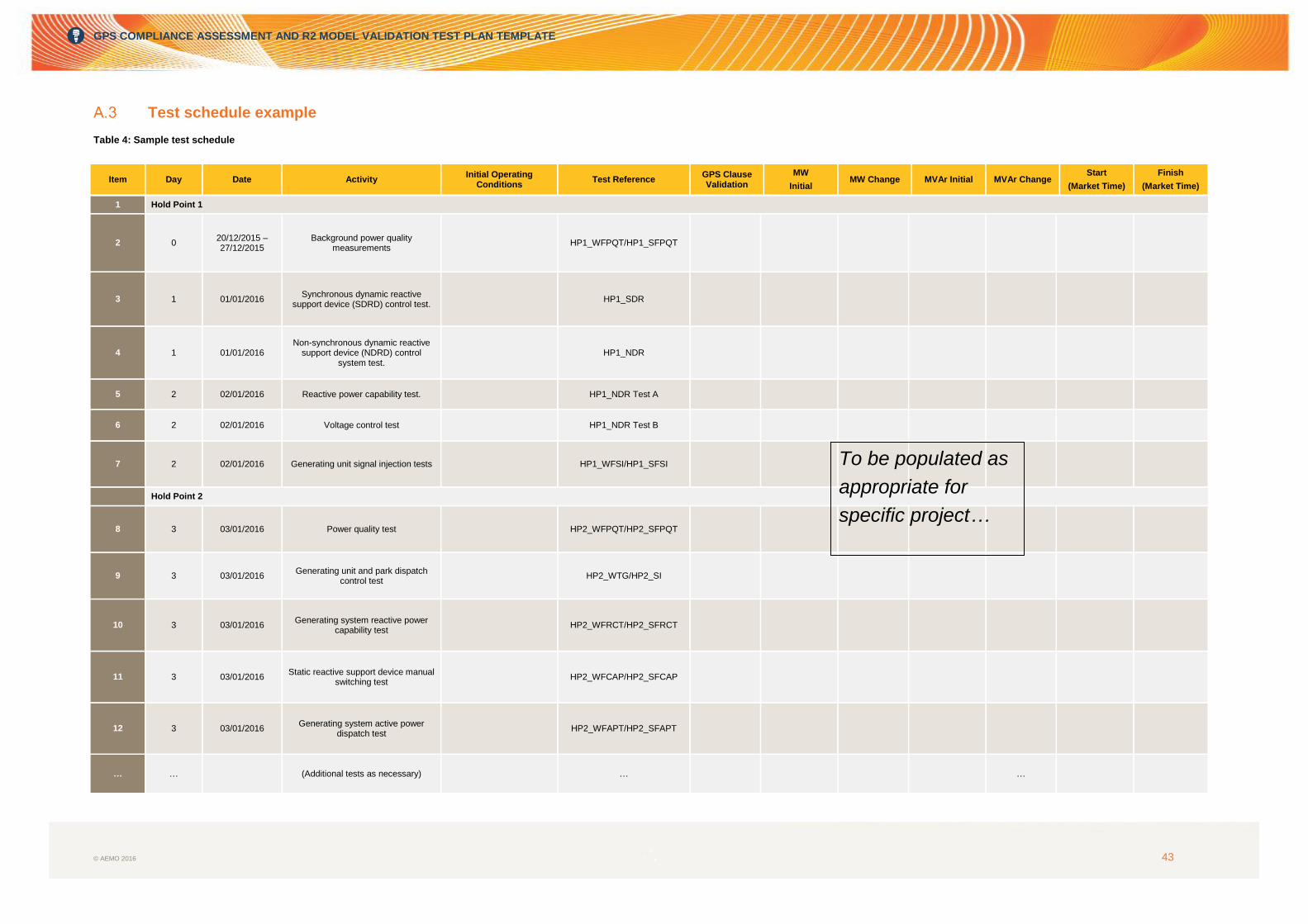
Test schedule example
Table 4: Sample test schedule
Item Day Date Activity Initial Operating
Conditions Test Reference
GPS Clause Validation
MW
Initial MW Change MVAr Initial MVAr Change
Start
(Market Time)
Finish
(Market Time)
1 Hold Point 1
2 0 20/12/2015 – 27/12/2015
Background power quality measurements
HP1_WFPQT/HP1_SFPQT
3 1 01/01/2016 Synchronous dynamic reactive
support device (SDRD) control test. HP1_SDR
4 1 01/01/2016 Non-synchronous dynamic reactive
support device (NDRD) control system test.
HP1_NDR
5 2 02/01/2016 Reactive power capability test. HP1_NDR Test A
6 2 02/01/2016 Voltage control test HP1_NDR Test B
7 2 02/01/2016 Generating unit signal injection tests HP1_WFSI/HP1_SFSI
Hold Point 2
8 3 03/01/2016 Power quality test HP2_WFPQT/HP2_SFPQT
9 3 03/01/2016 Generating unit and park dispatch
control test HP2_WTG/HP2_SI
10 3 03/01/2016 Generating system reactive power
capability test HP2_WFRCT/HP2_SFRCT
11 3 03/01/2016 Static reactive support device manual
switching test HP2_WFCAP/HP2_SFCAP
12 3 03/01/2016 Generating system active power
dispatch test HP2_WFAPT/HP2_SFAPT
… … (Additional tests as necessary) … …
To be populated as
appropriate for
specific project…

GPS COMPLIANCE ASSESSMENT AND R2 MODEL VALIDATION TEST PLAN TEMPLATE
© AEMO 2016 44
15 5 05/01/2016 Generating system reactive power
dispatch test HP2_WFRPT/HP2_SFRPT
16 5 03/01/2016 Generating system voltage reference
step test HP2_WFVCT/HP2_SFVCT
17 5 05/01/2016 Generating system power factor
reference step test HP2_WFPFT/HP2_SFPFT
Hold Point 3
20 6 05/01/2016 Power quality test HP3_WFPQT/HP3_SFPQT
21 6 06/01/2016 Generating system reactive power
capability test HP3_WFPQT/HP3_SFPQT
22 6 06/01/2016 Generating system active power
dispatch test HP3_WFAPT/HP3_SFAPT
23 6 06/01/2016 Generating system reactive power
dispatch test HP3_WFRPT/HP3_SFRPT
24 6 06/01/2016 Generating system power factor
reference step test HP3_WFPFT/HP3_SFPFT
25 6 06/01/2016 Generating system transformer manual tap position change test
HP3_WFTXT/HP3_SFTXT
… … (Additional tests as necessary) … …
29 Hold Point 4
30 10 10/01/2016 Partial generating system trip test
HP4_PWFTT/HP4_PSFTT
… … (Additional tests as necessary) … …
36 14 08/01/2016 Solar/Windfarm released for
unrestricted commercial operation
To be populated as
appropriate for
specific project…

GPS COMPLIANCE ASSESSMENT AND R2 MODEL VALIDATION TEST PLAN TEMPLATE
© AEMO 2016 45
Load profile example
Figure 6: Load profile example
Please note: The daily load profile indicated above, only includes certain selected active power and reactive power tests specified in this test plan and must be amended in-line with the commissioning schedule.
0
0.2
0.4
0.6
0.8
1
1.2
07:0
0
07:1
5
07:3
0
07:4
5
08:0
0
08:1
5
08:3
0
08:4
5
08:4
6
08:4
7
08:4
8
08:4
9
08:5
0
08:5
1
08:5
2
08:5
3
08:5
4
09:0
0
09:1
5
09:1
6
09:1
7
09:1
8
09:1
9
09:2
0
09:2
1
09:2
2
09:2
3
09:2
4
09:2
5
09:2
6
09:2
7
09:2
8
09:2
9
09:3
0
09:3
1
09:3
2
09:3
3
09:3
5
09:4
0
14:3
0
14:4
5
15:0
0
15:1
5
15:3
0
15:4
5
16:0
0
16:1
5
16:3
0
Unit L
oad L
evel M
W a
nd M
VA
r
AEMO Market Time
P(p.u.)
Q(p.u.)

GPS COMPLIANCE ASSESSMENT AND R2 MODEL VALIDATION TEST PLAN TEMPLATE
© AEMO 2016 46
Measurement point layout example
Figure 7: Measurement point layout

GPS COMPLIANCE ASSESSMENT AND R2 MODEL VALIDATION TEST PLAN TEMPLATE
© AEMO 2016 47
MEASURES AND ABBREVIATIONS
Abbreviation Expanded name
AEMO Australian Energy Market Operator
FCAS Frequency Control Ancillary Service
GPS Generator Performance Standard
HP Hold Point
HV High voltage
ITP Inspection and Testing Procedure
LV Low voltage
MV Medium voltage
NER National Electricity Rules
NDRD Non-synchronous dynamic reactive support device
NSP Network Service Provider
PoC Point of Connection
pu Per-unit
RMS Root mean square
RUG Releasable user guides
SDRD Synchronous dynamic reactive support device
SFTXT Solar farm transformer tapping
SI Solar inverter
WTG Wind turbine generator