GIMP - Urząd Miasta Łodzimath.uni.lodz.pl/~marekbad/files/gimp/gimp_manual.pdf · viii The Gimp...
924
GIMP USER’S MANUAL THE COMPLETE GUIDE TO GIMP Karin Kylander & Olof S Kylander
Transcript of GIMP - Urząd Miasta Łodzimath.uni.lodz.pl/~marekbad/files/gimp/gimp_manual.pdf · viii The Gimp...

G
THE CO
Karin Kyland
IMPUSER’S MANUAL
MPLETE GUIDE TO GIMP
er & Olof S Kylander

GIMP: The Official Handbook
The Gimp User’s Manual version 1.0.1
Karin Kylander & Olof S. Kylander

m
fale
tin
of
fr
ror
e
President, CEOKeith Weiskamp
PublisherSteve Sayre
Acquisitions EditorMariann Hansen Barsolo
Marketing SpecialistBeth Kohler
Project EditorToni Zuccarini
Production CoordinatorsJon Gabriel
April Nielsen
Production ArtistChristine Foley
Cover DesignJody Winkler
Gimp: The Official Handbook© 1999 The Coriolis Group. All Rights Reserved.
This book may not be duplicated in any way without theexpress written consent of the publisher, except in the forof brief excerpts or quotations for the purposes of review.The information contained herein is for the personal use othe reader and may not be incorporated in any commerciprograms, other books, databases, or any kind of softwarwithout written consent of the publisher. Making copies ofthis book or any portion for any purpose other than yourown is a violation of United States copyright laws.
Limits Of Liability And Disclaimer Of WarrantyThe author and publisher of this book have used their besefforts in preparing the book and the programs containedit. These efforts include the development, research, andtesting of the theories and programs to determine theireffectiveness. The author and publisher make no warrantyany kind, expressed or implied, with regard to theseprograms or the documentation contained in this book.
The author and publisher shall not be liable in the event oincidental or consequential damages in connection with, oarising out of, the furnishing, performance, or use of theprograms, associated instructions, and/or claims ofproductivity gains.
TrademarksTrademarked names appear throughout this book. Rathethan list the names and entities that own the trademarks insert a trademark symbol with each mention of thetrademarked name, the publisher states that it is using thnames for editorial purposes only and to the benefit of thetrademark owner, with no intention of infringing upon thattrademark.
The Coriolis Group, LLC14455 N. Hayden Road, Suite 220Scottsdale, Arizona 85260
480/483-0192FAX 480/483-0193http://www.coriolis.com
Library of Congress Cataloging-in-Publication DataKylander, Olof.
GIMP: The Official Handbook by Olof and KarinKylander.
p. cm.ISBN 1-57610-520-21. Computer graphics. 2. GIMP (computer file) I.Kylander, Karin. II. Title.
T385.K866 1999006.6'869--dc21
99-38515CIP
Printed in the United States of America10 9 8 7 6 5 4 3 2 1
Olof S Kylander
Please look in the "Copying" file for the right License of this version of the book. The file is down loadable from http://manual.gimp.org. Since this is a pdf file of the book published by Coriolis it has the standard Coriolis copyright and license notice.
Olof S Kylander
The cover is a bit differernt in this pdf file. The version in this file is made by Karin Kylander.


T A B L E O F C O N T E N T S
About This Book .............................................................. xixAuthors xixGimp Contributions xxContributors To This Book xxiHow To Read This Book xxiiConventions xxivSymbols xxiv
PART IAbout Gimp
Chapter 1: What Is Gimp? ................................................1About The Gimp 2Gimp History 3The Future Of Gimp 6
Chapter 2: Default Shortcuts And Dynamic Key Bindings9
Dynamic Key Bindings 10Default Shortcuts In Gimp 11
Chapter 3: Don’t Underestimate The Power Of Gimp...19Creating Image Objects 20Handling Glass, Water And Reflections 24Transforming A Photograph To A Drawing 28Light, Motion And Texture Transformation 32Making A Montage 36
Ta b l e O f C o n t e n t s
PART IIGimp
Installation
Chapter 4: Obtaining And Installing Gimp................... 43How To Install Gimp Personal Files 44Obtaining Gimp 48
Chapter 5: Gimp For Photoshop Users .......................... 55Why Should I Use Gimp When I Have Photoshop? 56Migrating To Gimp 59Some Final Notes 70
PART IIIBasic
Functions
Chapter 6: Files And Preferences .................................. 75The File Menu 76Creating Images 77Guash 77Opening Files 79Saving Images 81Save Dialogs 85Mailing Images 94Displaying Images In The Root Window 94Printing Images 96Gimp Preferences 100Miscellaneous Features And Extensions 105
Chapter 7: Selection Tools............................................ 109Basic Controls 110Selection Control 110Moving Selections 112Rectangular And Elliptical Selection Tools 115Selection Options 116The Free-Hand Selection Tool 118Fuzzy Select 119The Bezier Selection Tool 120Intelligent Scissors 123
Chapter 8: Paint Tools ................................................... 127The Color Picker 128Palettes 129The Bucket Fill 130The Blend Tool Or Gradient Fill 131The Pencil And Paintbrush 137
v i T h e G i m p U s e r ’ s M a n u a l

Ta b l e O f C o n t e n t s
Brush Selection 138The Eraser Tool 139The Airbrush Tool 139The Clone Tool 140The Convolver 141The Foreground/Background Icons 142
Chapter 9: Edit And View ............................................. 145Cut, Copy And Paste 146Multiselect 148Clear, Fill And Stroke 149Zoom 150Rulers And Guides 151Undo And Redo 152New View, Shrink Wrap And Window Info 152
Chapter 10: Transform Tools ......................................... 155The Move Tool 156The Crop Tool 158The Transform Tool 159The Flip Tool 162The Magnify Tool 162
Chapter 11: Text And Fonts .......................................... 165The Text Tool 166
Chapter 12: Brushes, Gradients,Palettes And Patterns.................................................. 171
Brushes 172Patterns 173Palettes 176The Gradient Editor 177
PART IVPre-press
Knowledge
Chapter 13: Color Models ............................................ 187RGB 188CMYK 189Indexed 189HSV 191NCS 192Spot Color 193
T h e G i m p U s e r ’ s M a n u a l v i i
Ta b l e O f C o n t e n t s
Grayscale And Line Art 194Complementary Or Inverted Colors 194
Chapter 14: Pre-press And Color In Gimp .................. 197What Is Pre-press? 198Printing From Gimp 198Preparing For The Press 201At The Print Shop 203Scanning Using A UNIX Or Linux System 205Calibration 206Color Calibration 208In-Depth Information 210Resolution 212Tables 216
Chapter 15: Scanning And Scanners .......................... 219Scanning In Gimp 220What Scanner To Buy 220What All Those Specs Really Mean 221Installing Sane 226Using Sane In Gimp 249Scanning With A Flatbed Scanner 250Scanning, The Web And Printing 259Scanning Other Objects 261
PART VMore Gimp
Functions
Chapter 16: Image Menu............................................. 265RGB, Grayscale And Indexed 266Resize and Scale 267Histogram 269Save Palette 270Transforms 270
Chapter 17: Image Menu: Colors ................................ 273Colors 274Equalize 274Invert 275Posterize 276Threshold 276Color Balance 278Brightness-Contrast 279
v i i i T h e G i m p U s e r ’ s M a n u a l

Ta b l e O f C o n t e n t s
Hue-Saturation 280Curves 282Levels 284Desaturate 289Auto-Stretch Contrast 289Auto-Stretch HSV 289Normalize 290Colorcube Analysis 291
Chapter 18: Image Menu: Channel OpsAnd Alpha.................................................................... 293
The Channel Ops Menu 294Alpha 303
Chapter 19: Select Menu.............................................. 307Creating Selections 308Adjusting Selections 309Special Selection Commands 310
Chapter 20: Layers And Floating Selections............... 315Introduction 316Basic Layer Operations 317Mask, Alpha And Selection Operations 322Layer Align, Adjust And Move Operations 326Transforms 330Floating Selections 331
Chapter 21: Modes ....................................................... 335What Are Modes? 336Comparing Different Modes 344
Chapter 22: Channels And Duotones ......................... 351RGB Channels 352Alpha Channels 353Using Channels For Spot Color Separation 355
PART VIFilters
Chapter 23: An Introduction To Filters ......................... 365Plug-ins 366
T h e G i m p U s e r ’ s M a n u a l i x

Ta b l e O f C o n t e n t s
Chapter 24: Animation Filters....................................... 369Animation Filters In The Filters Menu 370How To Create A GIF Animation 371
Chapter 25: Artistic Filters ............................................. 375Apply Canvas 376Apply Carpet 376Cubism 377GAG 377Gimpressionist 380Mosaic 387Newsprint 389Oilify 392Van Gogh (LIC) 392Warp 396
Chapter 26: Blur Filters .................................................. 401Antialias 402Blur 402Gaussian Blur 403Motion Blur 404Pixelize 406Selective Gaussian Blur 406Tileable Blur 407Variable Blur 407Antialias... 408
Chapter 27: Color Filters ............................................... 411Adjust Fgrd. - Bkgrd. 412Alien Map 412Alien Map2 418Border Average 419Color Mapping 419Color Exchange 420Colorify 422Colormap Rotation 422Filter Pack 426FS-Dither 429Gradient Map 430
x T h e G i m p U s e r ’ s M a n u a l

Ta b l e O f C o n t e n t s
Hot 431Max RGB 432Quantize 432RGB Displace 433Sample Colorize 434Scatter HSV 439Semi-Flatten 439Smooth Palette 441Value Invert 441
Chapter 28: Combine Filters ........................................ 443Depth Merge 444Film 447Fuse 448
Chapter 29: Cryptographic Filters ............................... 453Digital Signature 454Encrypt & Decrypt 454Gimp Mask 455Stegano 456
Chapter 30: Distort Filters .............................................. 459Bend 460Blinds 461Curtain 462Emboss 463Engrave 464IWarp 465Pagecurl 468Polar Coords 470Ripple 473Shift 474Twist 474Value Propagate 477Waves 479Whirl And Pinch 480Wind 482
T h e G i m p U s e r ’ s M a n u a l x i
Ta b l e O f C o n t e n t s
Chapter 31: Edge-Detect Filters................................... 485Introduction 486Edge 486Laplace 487LoG 487Sobel 489
Chapter 32: Enhance Filters ......................................... 493Adaptive Contrast 494Deinterlace 494Despeckle 494Destripe 496NL Filter 497Sharpen 498Unsharp Mask 498
Chapter 33: Generic Filters .......................................... 503Convolution Matrix 504Universal Filter 506User Filter (Adobe Filter Factory Emulator) 507
Chapter 34: Glass Effect Filters..................................... 509Apply Lens 510Conical Anamorphose And Central Reflection 510Ellipse 512Glass Tile 512RaX Structurizer 513Refract 514
Chapter 35: Light Effect Filters ...................................... 517FlareFX 518Gflare 519Light Effects 524Sparkle 532Super Nova 536
Chapter 36: Map Filters ................................................ 539Bump Map 540Coordinate Map 542
x i i T h e G i m p U s e r ’ s M a n u a l

Ta b l e O f C o n t e n t s
Displace 542Fractal Trace 549Illusion 550Make Seamless 550Map Object 551Paper Tile 558Small Tiles 558Tile 560
Chapter 37: Miscellaneous Filters................................ 563Diff 564ImageMap 565Magic Eye 572Stereogram 573Video 575
Chapter 38: Noise Filters............................................... 577Noisify 578Randomize, Hurl, Pick And Slur 578Spread 580
Chapter 39: Render Filters ............................................ 583CML Explorer 584Checkerboard 586Diffraction Patterns 587Dynamic Text 588Figures 591Flame 592Fractal Explorer 595Genetic 599Gfig 600Grid 611HFG 611Harmonic Colors 612IFS Compose 613Jigsaw 619L-Systems 620Maze 626NCP 627Plasma 628
T h e G i m p U s e r ’ s M a n u a l x i i i

Ta b l e O f C o n t e n t s
Photo Mosaic 628Random Path 630Qbist 631Sinus 632Solid Noise 634
PART VIIMiscellaneous
GimpFunctions
Chapter 40: Advanced Animation With GimpOr How To Use AnimFrames ....................................... 639
Basic Concepts 640How To Create An Animation With AnimFrames 640Your First Animation 642Move Beyond The Basics With The Move Path Tool 643The AnimFrame Menu 647Filter Layers 651Animation Gallery/Tutorial 651
Chapter 41: Drawing Tablets And Gimp ..................... 657Introduction 658Using The Pen As A Mouse Replacement 659The Wacom Intuos Tablet 671A Sneak Preview Of Gimp 1.1.x 674Using Tablets With Gimp 674
PART VIIIScript-Fu
Chapter 42: Script-Fu: Description And Function....... 687Script-Fu? 688Standalone Scripts 689Image-Dependent Scripts 692
Chapter 43: Mike Terry’s Black BeltSchool Of Script-Fu ..................................................... 697
The Road To Script-Fu Mastery 698Lesson 1: Getting Acquainted With Scheme 699Lesson 2: Of Variables And Functions 701Lesson 3: Lists, Lists And More Lists 703Lesson 4: Your First Script-Fu Script 708Lesson 5: Giving Our Script Some Guts 713Lesson 6: Extending The Text Box Script 716
x i v T h e G i m p U s e r ’ s M a n u a l
Ta b l e O f C o n t e n t s
PART IXPerl-Fu
Chapter 44: A Perl Introduction ................................... 725Introduction 726Perl-Fu Installation And Configuration 727Crash Course 728
Chapter 45: A Tutorial For Perl Gimp Users ................. 735Background 736What You Need 736The Gimp Module 736The Gimp PDB 737Object-Oriented Syntax 743Painting Areas With Selections 743Creating Text 747Floating Selections 750The Perl Server And Standalone Scripts 752End Notes, Links And References 753
PART XAdvanced
Installations
Chapter 46: How To Get Fonts To Gimp....................... 759How Fonts Work In Gimp 760Installing Fonts 761Tables 764
Chapter 47: Compiling Plug-ins................................... 769Compile 770How To Obtain And Install The Source Code 771Compiling The Code 771
PART XIAppendixes
Appendix A: Gimp Start Flags And rcfiles . . . . . . . . 785Gimp Command Line Switches AKA Flags (Options) 786Installing A New Version Of Gimp 789Initialization Files AKA rc-files 789
Appendix B: Gimp Man Pages . . . . . . . . . . . . . . . . . 799The Gimp Man Page 800The gimp-tool Man Page 804
Appendix C: SIOD: Scheme In One Defune,Reference Appendix . . . . . . . . . . . . . . . . . . . . . . . . . 807
Reference Section For Built-in Procedures 808
T h e G i m p U s e r ’ s M a n u a l x v

Ta b l e O f C o n t e n t s
Appendix D: Perl-Fu Man Pages. . . . . . . . . . . . . . . . 835Gimp Man Page 836Gimp::Fu Man Page 843Gimp::OO Man Page 849Gimp::Data Man Page 853Gimp::Util Man Page 854Gimp::Pixel Man Page 856Gimp::Compat Man Page 858Gimp::Feature Man Page 859Gimp::Config Man Page 861Gimp::Pod Man Page 861Gimp::Net Man Page 863Gimp::Lib Man Page 864Gimp::PDL Man Page 865Gimp::UI Man Page 866
Appendix E: Sane-Supported Scanners. . . . . . . . . . 869Legend 870
Appendix F: Links And References. . . . . . . . . . . . . . 877Links 878
Index: . . . . . . . . . . . . . . . . . . . . . . . . . . . . . . . . . . . . . 883:
x v i T h e G i m p U s e r ’ s M a n u a l


About This Book
m the5.PCsee now
sam-
heht his
er sys- Sys-f this
AUTHORS
KARIN KYLANDER
Karin is a designer and illustrator, and also an architect with a Master’s degree in Architecture froChalmers University of Technology. She has been working with graphic design and art since 198Computer aided design caught her interest in the late 1980s. At first, she worked with Macs and using programs like Photoshop, PageMaker, Corel DRAW and Illustrator. In 1996, she entered thUNIX arena, and in 1997, she started using Gimp for image manipulation and graphic design. Shuses Gimp on a daily basis.
Most of Karin’s work focuses on publications, posters and exhibition displays. If you’d like to see ples of her work, you have only to leaf through the Gallery chapter in this book.
OLOF S. KYLANDER
Olof is a UNIX and network system administrator. He received his formal computer education at tChalmers University of Technology. He has been into computers since the early 1980s. UNIX caugattention in 1993, and he has been configuring various UNIX systems and networks ever since.
Olof currently works for the UNIX/Network consulting company Sigma-nbit in Gothenburg, and ispresently occupied with configuring Solaris servers for Ericsson. He also has experience with othtems such as Mac, Windows, NT, Citrix and Novell. His specialties are thin clients and X Windowtem configuration, as well as Internet technologies. He is the author of the more technical parts obook.
T h e G i m p U s e r ’ s M a n u a l x i x

A b o u t T h i s B o o k
g inuchn up-a leaf-anip-
ech,k,
ylor,rdit,ick
Marc
rton,, Tim
on
mas
inson,otten
FROZENRIVER
Frozenriver, Karin’s company, deals with digital design in various fields as well as providing trainindigital image manipulation. The company specializes in different kinds of informational material, sas technical documentation/reports, brochures, magazines and exhibitions. Web design is also aand-coming service. Frozenriver can provide the entire range from a full advertisement concept tolet at the local mall. Frozenriver can also provide support for Gimp users (along with other image mulating programs such as Photoshop) in the form of training courses and advice by email.
If you wish to contact Frozenriver, please visit our website athttp://www.frozenriver.nu ormail us [email protected] .
Or even better, contact us directly:
FrozenriverKarin KylanderN.Dragspelsg 12S-421 43 V.FRÖLUNDASWEDENPhone: +46 (0)31 47 43 56Fax: +46 (0)31 49 48 33
GIMP CONTRIBUTIONS
First, we’d like to thank the many Gimp developers:
Spencer Kimball, Peter Mattis, Federico Mena, Zach Beane, Adrian Linkns, Miguel de Icaza, Tom BSven Neumann, Albert Cahalan, Adam D. Moss, Torsten Martinsen, Tristan Tarrant, Andreas BecDavid Mosberger, Gordon Matzigkeit, Peter Kirchgessner, Eric L. Hernes, Francisco Bustamante,Thorsten Schnier, Jochen Friedrich, Tim Newsome, Christoph Hoegl, Xavier Bouchoux, Owen TaAndy Thomas, Ray Lehtiniemi, Marcelo Malheiros, Miles O’Neal, Chris Laas, Daniel Risacher, GeKnorr, Michel Taylor, Ole Steinfatt, Michael Sweet, Eiichi Takamori, Tracy Scott, Gordon MatzigkeAndrew Kieschnick, Alexander Schulz, Thomas Noel, Robert L.Cross, Kevin Turner, Sean Cier, NLamb, Kim-Minh Kaplan, Matthias Cramer, Lauri Alanko, Tim Newsome, Bucky LaDieu, ScottGoehring, Morten Eriksen, Raphael Quinet, Daniel Skarda, Daniel Dunbar, Jens Ch. Restemeier,Lehmann, Scott Draves, Alessandro Baldoni, Michael Schubart, Dan Risache, Josh MacDonald,Eduardo Perez, Daniel Cotting, Nathan Summers, John Beale, Marc Bless, John Breen, Brent BuJim Geuther, Pavel Grinfeld, Matthias Greim, Jan Hubicka, Shuji Narazaki, Stephen Robert NorrisRowley, Christoph Hoegl, Wolfgang Hofer, Shawn Amundson, Edward Blevins, Roberto Boyd, SimBudig, Seth Burgess, Ed Connell, Jay Cox, Andreas Dilger, Austin Donnelly, Misha Dynin, LarryEwing, Nick Fetchak, David Forsyth, Heilco Goller, Michael Hammel, Simon Jones, Tim Janik, TuoKuosmanen, Karl LaRocca, Jens Lautenbacher, Laramie Leavitt, Elliott Lee, Ralph Levien, AdrianLikins, Tor Lillqvist, Ingo Luetkebohle, Ed Mackey, Vidar Madsen, Ian Main, Michael Natterer, ErikNygren, Tomas Ogren, Jay Painter, Asbjorn Pettersen, Mike Phillips, Mike Schaeffer, James RobManish Singh, Ian Tester, James Wang, Kris Wehner, Matthew Wilson and all of you we have forg(if we’ve forgotten you, please write [email protected] to let us know).
x x T h e G i m p U s e r ’ s M a n u a l

C o n t r i b u t o r s To T h i s B o o k
, con-
CONTRIBUTORS TO THIS BOOK
We’d also like to give credit to everyone that came up with suggestions, tips, constructive criticismtributions, etc:
• Dov Grobgeld (Author of “A Tutorial For Perl Gimp Users”)
• Mike Terry (Author of “Black Belt School Of Script-Fu”)
• John Sigerson (PDF file format of GUM version 0.5 to 0.9)
• Aristidi Yannick (French translation)
• Yasuhiro Shirasaki (Leader of the Japanese translation team)
• Mark Probst (Documentation)
• Peter Uray (Documentation)
• Petri Alanko (Documentation)
• Ole Steinfatt (Documentation)
• Michal Gomulinski (Documentation)
• George J. Carret (Documentation)
• PhotoDisc (For their kind donation of high-quality images for this book project)
• Thom van Os (Images in Selective Gaussian Blur)
• Eric Galluzzo and Christopher Macgowan (Proofreading)
• Nicholas Lamb (Tip about selections)
• Michael Kaiser (Correction layers)
• Cristoph Hogeld (Contrib correction)
• Marco Schmidt
• Adrian Links
• Adam D. Moss (Tips about animation filters and psd)
• Tom Bech (Tips & lesson about light effects and map objects)
• Nathan Carl Summers (Tips & lesson about scissors)
• Wolfgang Hofer (Tips about animframe)
• Markku Verkkoniemi (Tip in Pre-Press about image delivery)
• Matt Chisholm (Found a bug in the font install chapter)
• and anyone that we’ve forgotten (please write [email protected] and let us know!)
T h e G i m p U s e r ’ s M a n u a l x x i

A b o u t T h i s B o o k
rcean-
asicusing
ougrams
an beturesscript-X (a
me
HOW TO READ THIS BOOK
GIMP: The Official Handbookis the complete Gimp user’s manual. It is the most comprehensive souof Gimp information available, covering nearly all aspects of this complex application. It’s a user mual, so it will not cover “nuts and bolts” topics such as how to write Gimp plug-ins; however, some bscripting tutorials have been included. All images in this manual have been created or manipulatedGimp — no other software has been used.
GIMP: The Official Handbookis divided into several parts. If you are an experienced graphics artist, ycan read the first parts quickly in order to pick up the main differences between Gimp and the proyou are used to working with.
This book also covers features that aren’t part of the standard Gimp distribution. These features cfound in the developer’s version, or at the Plug-in Registry. We have covered all available Gimp feaup to August 1999, with the exception of how to use pressure-sensitive drawing tablets, Gimp Perling extensions, Dumpwindow, xmorph (a Gimpified version of the xmorph program) and HaruspexSQL Gimp extension).
Part I
• What is Gimp; a briefhistory of Gimp and GTK+
• Gimp’s defaultshortcuts(accelerator keys) and how to reassign them
• A gallery showing what you can achieve with the powerful resources of Gimp and providing soinsight intoadvanced image manipulation.
Part II
• How toget andinstall Gimp for your system andtroubleshooting
• Migrating fromPhotoshop to Gimp
Part III
• What file formats Gimp supports and how to use them; how toopen andsave files in Gimp
• Personaladjustments
• How to use the differentpaint tools
• How you can use the different edit functions
• Transformation functions
• How to work withtext
• How to use theGradient Editor as well as information aboutbrushes, palettes andpatterns
Part IV
• A general discussion aboutcolor models(to understand how differentmodeswork in Gimp, you needthe information in this chapter)
• How to prepare your Gimp image forpre-press
• Calibration discussion and a simple calibration of your system
x x i i T h e G i m p U s e r ’ s M a n u a l

H ow To R e a d T h i s B o o k
• Scanning, discussion of scanner types and what to buy.
• Installation of Sane (Gimp’s scanner interface) and usage of Sane within Gimp
Part V
• In-depth discussion about theimage menu, which includescolor, brightness, curves and other imageadjustments (also covers imageconversions like RGB to Indexed, as well as image transformations)
• How to use differentselection methods
• How modes work in Gimp
• In-depth discussion on how to use layers — the key factor to advanced image manipulation
• Channels: What they are and how to use them
Part VI
• Thefilter plug-ins available for Gimp; a glimpse of what they’re all about
• Differentcolor exchange filters
• How to use thelighting effects
• How to render fantastic patterns and images
Part VII
• Animations, or howAnimFrames can make it easy to create advanced web animations
• Xinput, usage and installation of Wacom tablets in Linux (XFree86)
Part VIII
• Discussion about the Script-Fus that come with Gimp
• Two different angles/tutorials on how to writeScript-Fusand how they can help youautomate Gimptasks
Part IX
• Discussion about the Perl-Fus that come with Gimp
• Two different angles/tutorials on how to writePerl-Fusand how they can help youautomate Gimptasks
Part X
• How fonts works in Gimp and the X Window System; how to install more fonts
• How tocompile plug-ins, make your ownmake file and use theconfigure script
Part XI
• Man pages in the Gimp distribution
• Initiation file descriptions as well as description ofcommand line flags
• SIOD reference for those who write Script-Fu scripts
• Links andbooks that can be useful
T h e G i m p U s e r ’ s M a n u a l x x i i i

A b o u t T h i s B o o k
le, be be
in a
adc-
tan-n the
u
e,
c-
CONVENTIONS
You’ll find four different typing styles besides the normal text in the GUM.
Bold is used the first time important concepts, items or topics are introduced. This can, for exampwords you’ll see onscreen in Gimp — pull-down menu titles, dialog titles, options — but it can alsoused in more general terms such as:color theory, font manager or halftone pattern.
Italics to emphasize important points. Bold italics for warnings.
Courier for describing the path to Gimp menu commands, programs you’ll need to execute withterminal window, file names and code.
SYMBOLS
Not A Standard Part Of The Gimp DistributionThis symbol will appear when a function or filter is not part of thestandard distribution of Gimp. This means that you have to downloit and probably compile it yourself. The primary source of extra funtions and plug-ins arehttp://registry.gimp.org or ftp://ftp.gimp.org/pub/gimp . If you bought the printed version ofthis book, the non-standard plug-ins and functions, as well as the sdard ones, have been included both as binaries and source code oenclosed CD.
Warning!Look out for this symbol. Its purpose is to catch your attention, so yowon’t miss passages of vital importance or essential warnings. Forexample, don’t do this or your system will crash, or some otherunpleasantness will happen!
Beware Of Bugs!This sign indicates that a filter or function is still in development stagand that it may suffer from bug problems. Install or use functionsmarked with this symbol at your own risk.
TutorialNext to this sign, you’ll find an example or a tutorial, helping you tounderstand the described function.
TipThis sign indicates useful tips or advice on how to use a certain funtion, or that a passage describing important subjects will follow.
This is the Swedish version of thecrossing traffic sign. In this case, itmeans that you have a crossroadsin front of you; either you installthe documented feature, or youignore the passage in question.
You had better look out when yousee this warning sign!
Install at your own risk, you maybe in for a bumpy ride.
We lead the way. Follow us for aguided tour.
Read the information carefully;this is stuff you need to know!
x x i v T h e G i m p U s e r ’ s M a n u a l


P A R T
I About Gimp• ABOUT GIMP AND GIMP HISTORY
• SHORTCUTS AND DYNAMIC KEY BINDINGS


C H A P T E R
1 What Is Gimp?A quick description of Gimp.

W h a t I s G i m p ?
om-
sedlinet con-
-inslowsage
l
ct
ABOUT THE GIMP
From the “About the Gimp” website athttp://www.gimp.org/ , we quotethe following:
Gimp is an acronym forGNU ImageManipulationProgram. Gimp is a freely dis-tributed piece of software suitable for such tasks as photo retouching, image cposition and image authoring.
It is an extremely capable piece of software with many capabilities. It can be uas a simple paint program, an expert quality photo retouching program, an onbatch processing system, a mass production image renderer, an image formaverter and more.
Gimp is expandable and extensible. It is designed to be augmented with plugand extensions to do just about anything. The advanced scripting interface aleverything to be easily scripted, from the simplest task to the most complex immanipulation procedures.
FEATURES AND CAPABILITIES
This is only a brief list of Gimp features:
• Full suite of painting tools including brushes, a pencil, an airbrush,cloning, etc.
• Tile-based memory management so image size is limited only byavailable disk space
• Sub-pixel sampling for all paint tools for high-quality anti-aliasing
• Full Alpha channel support
• Layers and channels
• A procedural database for calling internal Gimp functions from externaprograms, such as Script-Fu
• Advanced scripting capabilities
• Multiple undo/redo (limited only by disk space)
• Transformation tools including rotate, scale, shear and flip
• File formats supported include GIF, JPEG, PNG, XPM, TIFF, TGA,MPEG, PS, PDF, PCX, BMP and many others
• Load, display, convert and save to many file formats
• Selection tools including rectangle, ellipse, free, fuzzy, bezier andintelligent
• Plug-ins that allow for the easy addition of new file formats and new effefilters
2 T h e G i m p U s e r ’ s M a n u a l

C h a p t e r 1
el-sting.
thertiptionage
Mac
ig-
AUTHORS
The Gimp was written by Peter Mattis and Spencer Kimball. Many other devopers have contributed plug-ins and thousands have provided support and teGimp releases are currently being orchestrated by Manish Singh.
End quote (we couldn’t have said it better ourselves).
WHAT WE CAN SAY ABOUT GIMP
First, we want to congratulate Peter Mattis, Spencer Kimball and all of the odevelopers of this lovely program. The “About The Gimp” section is only theof the iceberg. Gimp is capable of everything from advanced image manipulato basic drawing. Many of its features are inspired by Photoshop and other immanipulation programs.
Karin, who is an architect and designer and a former Photoshop user in bothand Windows environments, can only say this:
Compared to Photoshop, Gimp has it all (and even more if you don’tbuy third-party Photoshop plug-ins). Most of the features in Gimp aremore flexible and powerful once you get to know them. The great thing isthat Gimp supports the PSD file format and Filter Factory files, so youcan easily switch from Photoshop to Gimp. Simply, it’s a heck of a pro-gram and it comes loaded with a sack of plug-ins. So GO AND GET IT!!You will not be disappointed, and, well, it’s not wrong that it is free.
Karin Kylander & Olof S. Kylander
GIMP HISTORY
0.54
We’ll quote a bit more, this time from Peter Mattis and Spencer Kimball, the orinal creators of Gimp, in their announcement of Gimp 0.54:
The Gimp arose from the ashes of a hideously crafted cs164 (compilers)class project. The setting: early morning. We were both weary from lackof sleep and the terrible strain of programming a compiler in LISP. Thelimits of our patience had long been exceeded, and yet still the damheld.
And then it happened. Common LISP messily dumped core when itcould not allocate the 17 MB it needed to generate a parser for a simplegrammar using yacc. An unbelieving moment passed, there was oneshared look of disgust, and then our project was vapor. We had to writesomething...ANYTHING...useful. Something in C. Something that didnot rely on nested lists to represent a bitmap. Thus, the Gimp was born.
T h e G i m p U s e r ’ s M a n u a l 3

W h a t I s G i m p ?
firstro-
ms.
se)
dailyde-as
oualso
Like the phoenix, glorious, new life sprung out of the burnt remnants ofLISP and yacc. Ideas went flying, decisions were made, the Gimp beganto take form.
An image manipulation program was the consensus. A program thatwould at the very least lessen the necessity of using commercial soft-ware under ‘Windoze’ or on the ‘Macintoy.’ A program that would pro-vide the features missing from the other X painting and imaging tools. Aprogram that would help maintain the long tradition of excellent andfree UNIX applications.
Six months later, we’ve reached an early beta stage. We want to releasenow to start working on compatibility issues and cross-platform stabil-ity. Also, we feel now that the program is actually usable and would liketo see other interested programmers developing plug-ins and variousfile format support.
Version 0.54 was released in February 1996, and had a major impact as thetruly professional free image manipulation program. This was the first free pgram that could compete with the big commercial image manipulation progra
Version 0.54 featured:
• Support for 8, 15, 16 and 24 bit color
• Ordered and Floyd-Steinberg dithering for 8 bit displays
• Viewing images as RGB color, grayscale or indexed color
• Simultaneous editing for multiple images
• Zooming and panning in real-time
• GIF, JPEG, PNG, TIFF and XPM support
• Selection tools including rectangle, ellipse, free, fuzzy, bezier andintelligent scissors
• Transformation tools including rotate, scale, shear and flip
• Painting tools including bucket, brush, airbrush, clone, convolve, blendand text
• Effects filters (such as blur and edge detect)
• Channel and color operations (such as add, composite and decompo
• Plug-ins that allowed for the easy addition of new file formats and neweffect filters
• Multiple undo/redo (note that this is a new feature in Photoshop 5)
Version 0.54 was a beta release, but it was so stable that you could use it forwork. However, one of the major drawbacks of 0.54 was that the toolkit (the slibars, menus, dialog boxes, etc.) was built on Motif, a commercial toolkit. This wa big drawback for systems like Linux, because you had to buy Motif if ywanted to use the faster, dynamically linked Gimp. Many developers werestudents running Linux, who could not afford to buy Motif.
4 T h e G i m p U s e r ’ s M a n u a l
C h a p t e r 1
eter)ool--
readand
as the
S&Pin dif-pts;by.99uge
on
ev-suchngto
dropotherake
izedwn
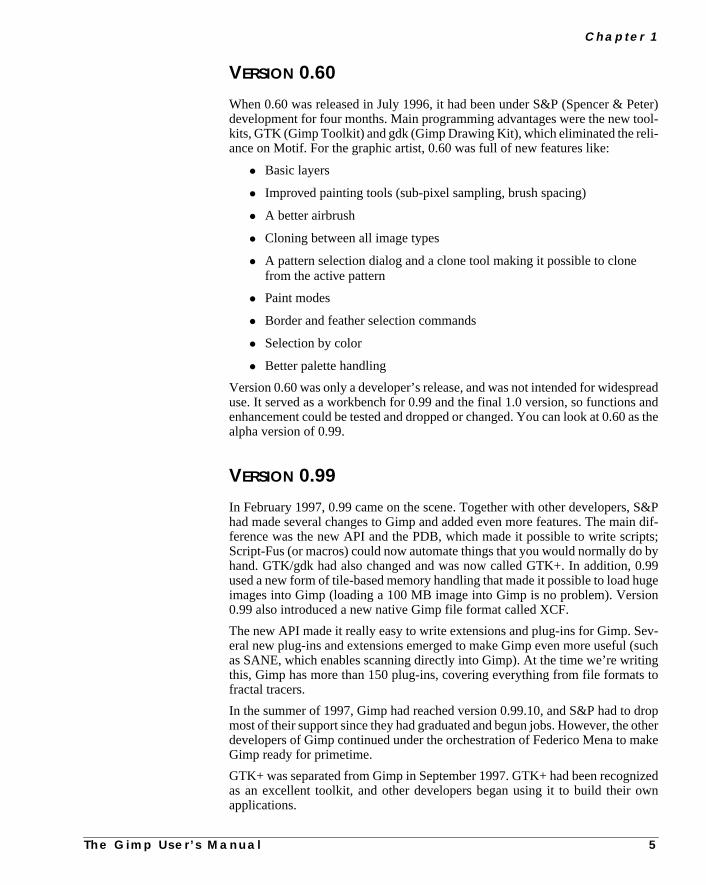
VERSION 0.60
When 0.60 was released in July 1996, it had been under S&P (Spencer & Pdevelopment for four months. Main programming advantages were the new tkits, GTK (Gimp Toolkit) and gdk (Gimp Drawing Kit), which eliminated the reliance on Motif. For the graphic artist, 0.60 was full of new features like:
• Basic layers
• Improved painting tools (sub-pixel sampling, brush spacing)
• A better airbrush
• Cloning between all image types
• A pattern selection dialog and a clone tool making it possible to clonefrom the active pattern
• Paint modes
• Border and feather selection commands
• Selection by color
• Better palette handling
Version 0.60 was only a developer’s release, and was not intended for widespuse. It served as a workbench for 0.99 and the final 1.0 version, so functionsenhancement could be tested and dropped or changed. You can look at 0.60alpha version of 0.99.
VERSION 0.99
In February 1997, 0.99 came on the scene. Together with other developers,had made several changes to Gimp and added even more features. The maference was the new API and the PDB, which made it possible to write scriScript-Fus (or macros) could now automate things that you would normally dohand. GTK/gdk had also changed and was now called GTK+. In addition, 0used a new form of tile-based memory handling that made it possible to load himages into Gimp (loading a 100 MB image into Gimp is no problem). Versi0.99 also introduced a new native Gimp file format called XCF.
The new API made it really easy to write extensions and plug-ins for Gimp. Seral new plug-ins and extensions emerged to make Gimp even more useful (as SANE, which enables scanning directly into Gimp). At the time we’re writithis, Gimp has more than 150 plug-ins, covering everything from file formatsfractal tracers.
In the summer of 1997, Gimp had reached version 0.99.10, and S&P had tomost of their support since they had graduated and begun jobs. However, thedevelopers of Gimp continued under the orchestration of Federico Mena to mGimp ready for primetime.
GTK+ was separated from Gimp in September 1997. GTK+ had been recognas an excellent toolkit, and other developers began using it to build their oapplications.
T h e G i m p U s e r ’ s M a n u a l 5

W h a t I s G i m p ?
ureswasake
sta-
wen-veneoork
ion.
it toance-
’t
Gimp went into feature freeze in October 1997. This meant that no new featwould be added to the Gimp core libraries and program. GUM version 0.5also released early in October 1997. The developing work continued to mGimp stable and ready for version 1.0.
VERSION 1.0
Gimp version 1.0 was released on June 5, 1998. Finally, Gimp was consideredble enough to warrant a worldwide announcement and professional use.
THE FUTURE OF GIMP
Gimp will naturally continue to evolve. The future is bright, and we will see neversions of Gimp with new features and functions. The version naming convtion of Gimp is the same as for Linux, meaning that stable versions will have epoint release numbers (such as 1.0.X), whereas the development version will havodd point release numbers (like 1.1.X). This makes it possible for normal users tgrab the stable version and use it for a primetime job, while the developers won a bleeding-edge version without introducing new bugs into the stable vers
If you want to, you can always download the development version and testcheck out new features and give the developers feedback about bugs and enhments. But be aware, itwill be unstable, so don’t use it for daily work, and donflood the developers with unnecessary bug reports.
6 T h e G i m p U s e r ’ s M a n u a l


C H A P T E R
2 Default Shortcuts And Dynamic Key BindingsGimp has many accelerator keys that make imagemanipulation quicker and easier. Gimp also lets youassign shortcut keys on the fly.

1 0 T h e G i m p U s e r ’ s M a n u a l
D e fa u l t S h o r t c u t s A n d D y n a m i c Key B i n d i n g s
DYNAMIC KEY BINDINGS
Gimp has a very nice way of dealing withshortcuts (sometimes known ashot-keys). If you don’t like a default shortcut, or if your favorite command hasn’tbeen assigned to a default hotkey, just bring up the menu holding the command(for example,right-click|File| Preference ) and press the desiredkey sequence — say, Ctrl+U. From now on, the Preference dialog will pop upwhen you press Ctrl+U (remember to keep Caps Lock off). If the Ctrl+U keysequence was originally assigned to (for example)right-click|File|Print , the original shortcut will not be available. All of this happens on thefly — there is no need to restart Gimp.
Changes to key bindings can also be done by editing yourpersonal menurcfile in your personal gimp directory. This makes it possible to share your short-cuts with your friends. If you are a former Photoshop user, you can even re-bindyour keys so Gimp will use the same hotkeys as Photoshop.
We suggest that you stick to the default shortcuts; otherwise, it may be difficult tofollow our instructions. (For instance, you could run into some problems when wewrite Ctrl+N to get a new image, and you accidentally quit Gimp because you havereassigned the shortcut.) If you want to remove all your personal shortcuts, justtype “rm .gimp/menurc” in an xterm shell.
The next few pages list the default key bindings in Gimp.
CONVENTIONS
• The left column lists options available for a certain tool (clicking differentmouse buttons and/or pressing hotkeys). The right column describes theresult.
• The headings list the different tools in the left column and the hotkeys forcalling up each tool in the right column.
• {1} represents left mouse button
• {2} represents the middle mouse button
• {3} represents the right mouse button
• Shift + {1} - Shift + Shift + Ctrl means the following:First press Shift, then press the left mouse button. Release Shift then pressShift again. Press Ctrl and drag the mouse while holding Shift and Ctrl.When you are finished, first release the mouse button, then release Shiftand Ctrl.

C h a p t e r 2
DEFAULT SHORTCUTS IN GIMP
Selection Tools
{1} Draw selection
{1} + {3} - {1} Cancel selection
On existing selections
Shift + {1} - Shift Add to selection
Ctrl + {1} - Ctrl Subtract fromselection
Shift + Ctrl + {1} -Shift - Ctrl
Union of selection
Alt + {1} Move selection
Rectangular andellipse
Shortcut: R/E
{1} + Shift Circle/square only
{1} + Ctrl Start from center
{1} + Shift + Ctrl Start circle/squarefrom center
Shift + {1} - Shift +Shift
Add circle/square toselection
Shift + {1} - Shift +Ctrl
Add rect/ellipse toselection startingfrom center
Shift + {1} - Shift +Shift + Ctrl
Add circle/square toselection startingfrom center
Ctrl + {1} - Ctrl +Shift
Subtract circle/square fromselection
Ctrl + {1} - Ctrl +Ctrl
Subtract ellipse/square fromselection startingfrom center
Ctrl + {1} - Ctrl +Shift +Ctrl
Subtract circle/square from selec-tion starting fromcenter
Shift + Ctrl + {1} -Shift - Ctrl + Shift
Circle/square unionof selection
Shift + Ctrl + {1} -Shift - Ctrl + Ctrl
Ellipse/rectangleunion of selectionstarting from center
Shift + Ctrl + {1} -Shift - Ctrl + Shift +Ctrl
Circle/square unionof selection startingfrom center
Bezier Shortcut: B
{1} (inside bezier) Convert to selection
{1} Move both controlhandles
Shift + {1} Move one controlhandle
Ctrl + {1} Move control point
Remaining selection tools
Fuzzy select Z
Free F
Intelligent scissors I
T h e G i m p U s e r ’ s M a n u a l 1 1

D e fa u l t S h o r t c u t s A n d D y n a m i c Key B i n d i n g s
Move tool Shortcut: M
{1} Move current layer
{1} + Shift Move current even if100% transparent
Ctrl + [arrow key] Move layer 1 pixel
Shift + [arrow key] Move layer 25pixels
Alt + [arrow key] Move selection 1pixel
Alt + Shift +[arrow key]
Move selection 25pixels
Magnify tool Shortcut: Shift+ M
{1} or = Zoom in
Shift + {1} or - Zoom out
{2} Pan image
Crop tool Shortcut: Shift+ C
{1} Make crop selection
{1} + {3} -{1} Cancel crop
{1} inside crop Perform crop
Text tool Shortcut: T
{1} Set top left of text
Color picker tool Shortcut: O
{1} Get color
Transform tool Shortcut: Shift+ T
Rotation mode
{1} Rotate with 1˚increments
Ctrl + {1} Rotate with 15˚increments
Scaling mode
{1} Free scaling
Shift + {1} Scale in X directiononly
Ctrl + {1} Scale in Y directiononly
Shift + Ctrl + {1} Scale with fixedratio
Shearing mode
{1} Free shearing
Perspective mode
{1} Move point
All
{1} + {3} - {3} Preview
1 2 T h e G i m p U s e r ’ s M a n u a l

C h a p t e r 2
Bucket fill tool Shortcut: Shift +M
With no selection
{1} Fill with FG color
Shift + {1} Fill with BG color
With selection
{1} Fill selection with FGcolor
Shift + {1} Fill selection withBG color
Color picker tool Shortcut: O
{1} Set active color withcursor
X Swap BG FG color
D Set default colors
Blend tool Shortcut: L
{1} + drag - {1} Set start => end ofgradient
{1} + {2} - {1} Cancel gradient
Paint tools
Blend tool Shortcut: L
Pencil tool Shortcut: Shift+ P
Airbrush tool Shortcut: A
{1} Paint
Alt + {1} Quick draw
Shift +/- {1} +distance +/- {1}
Line draw
Eraser tool Shortcut: Shift+ E
{1} Set to BG and Clear
Alt + {1} Quick erase
Shift +/- {1} +distance +/- {1}
Line erase
Clone tool Shortcut: C
{1} Clone
Ctrl + {1} Set clone sourcepoint
Alt + {1} Quick clone
Shift +/- {1} + dis-tance +/-! {1}
Line clone
Convolver tool Shortcut: V
{1} Blur/Sharpen withbrush
T h e G i m p U s e r ’ s M a n u a l 1 3

D e fa u l t S h o r t c u t s A n d D y n a m i c Key B i n d i n g s
File Select
New Ctrl + N Toggle Ctrl + T
Open Ctrl + O Invert Ctrl + I
Close Ctrl + W All Ctrl + A
Quit Ctrl + Q None Shift + Ctrl + A
Float Shift + Ctrl + L
Dialogs Sharpen Shift + Ctrl + H
Brushes Shift + Ctrl + B Feather Shift + Ctrl + F
Patterns Shift + Ctrl + P
Palette Ctrl + P View
Gradient editor Ctrl + G Zoom in =
Tool options Shift + Ctrl + T Zoom out -
Layers & Channels Ctrl + L Zoom 1:1 1
Window info Shift + Ctrl + I
Edit Toggle rulers Shift + Ctrl + R
Cut Ctrl + X Toggle guides Shift + Ctrl + T
Copy Ctrl + C Shrink wrap Ctrl + E
Paste Ctrl + V
Clear Ctrl + K Image
Fill Ctrl + . Channel Ops Dupli Ctrl + D
Undo Ctrl + Z Channel Ops Offset Shift + Ctrl + O
Redo Ctrl + R
Cut Named Shift + Ctrl + X Layers
Copy Named Shift + Ctrl + C Dialog Ctrl + L
Paste Named Shift + Ctrl + V Raise Layer Ctrl + F
Lower Layer Ctrl + B
Filters Merge VisibleLayers
Ctrl + M
Repeat Last Alt + F
Re-show Last Shift + Alt + F
1 4 T h e G i m p U s e r ’ s M a n u a l

C h a p t e r 2
Tools Layers & Channels dialog
Rect Select R Layers ops menu
Ellipse Select E New layer Ctrl + N
Fuzzy Select Z Raise layer Ctrl + F
Bezier Select B Lower layer Ctrl + B
Intelligent Scissors I Duplicate layer Ctrl + C
Move M Delete layer Ctrl + X
Magnify Shift + M Scale layer Ctrl + S
Crop Shift + C Resize layer Ctrl + R
Transform Shift + T Merge visiblelayers
Ctrl + M
Flip Shift + F
Text T {1} Select layer (visi-ble and anchor)Color Picker O
Bucket Fill Shift + B Shift + {1} View current layeronlyBlend L
Paintbrush P Alt + {1}Green layer mask
View layer mask (orremove green mask)Pencil Shift + P
Eraser Shift + E Alt + {1}Green layer mask
View layer mask (orremove green mask)Airbrush A
Clone C Alt + {1}Green layer mask
View layer mask (orremove green mask)Convolve V
Channels ops menu
New channel Ctrl + N
Raise channel Ctrl + F
Lower channel Ctrl + B
Duplicate channel Ctrl + C
Delete channel Ctrl + X
Channel toselection
Ctrl + S
T h e G i m p U s e r ’ s M a n u a l 1 5

D e fa u l t S h o r t c u t s A n d D y n a m i c Key B i n d i n g s
Gradient Editor dialog: Ops menu Selection operands
Left endpoint color L Flip segments F
Load from leftneighbor’s rightendpoint
Ctrl + L Replicate segment M
Blend endpoints’colors
B
Load from rightendpoint
Alt + L Blend endpoints’opacity
Ctrl + B
Load from FG color Ctrl +
Right endpointcolor
R
Load from rightneighbor’s rightendpoint
Ctrl + R
Load from leftendpoint
Alt + R
Load from FG color Alt + F
Segments
Split segment atmidpoint
S
Split segmentuniformly
U
Delete segment D
Recenter segment’smidpoint
C
Redistribute han-dles in segment
Ctrl + C
1 6 T h e G i m p U s e r ’ s M a n u a l


C H A P T E R
3 Don’t Underestimate The Power Of Gimp...This manual describes the many functions, plug-insand options Gimp has to offer, but it doesn’t describehow to create great digital art or designs. There areprobably as many Gimp tricks and tips as there areGimp users, and even if we wanted to, we couldn’tinclude them all in this book.
We also can’t teach you how to be an artist, butwe’ve included a few examples that will hopefullyinspire you to try new things and help you get themost out of Gimp. This is more a gallery than a tuto-rial, and the object of this chapter is not to givedetailed instructions, but rather to demonstrate thegreat versatility and power of Gimp to beginners(and maybe to give more experienced users insightson new ways of using Gimp).
So let’s unleash the power of Gimp!

D o n ’ t U n d e r e s t i m a t e T h e Powe r O f G i m p . . .
rintede able
create
In some of the following examples, color will be mentioned. Because the images in this chapter are pin black and white, we recommend that you look them up in the Color Section starting on page 379 to bto follow the discussion.
CREATING IMAGE OBJECTS
You don’t always need to import a photo, drawing or 3-D image of an object. There are many ways toastonishingly convincing images directly in Gimp.
2 0 T h e G i m p U s e r ’ s M a n u a l
C h a p t e r 3
a-
d-
re
y was
and set
ide the
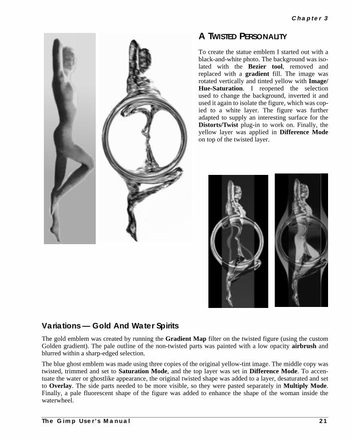
A TWISTED PERSONALITY
To create the statue emblem I started out withblack-and-white photo. The background was isolated with the Bezier tool, removed andreplaced with agradient fill. The image wasrotated vertically and tinted yellow withImage/Hue-Saturation. I reopened the selectionused to change the background, inverted it anused it again to isolate the figure, which was copied to a white layer. The figure was furtheadapted to supply an interesting surface for thDistorts/Twist plug-in to work on. Finally, theyellow layer was applied inDifference Modeon top of the twisted layer.
Variations — Gold And Water SpiritsThe gold emblem was created by running theGradient Map filter on the twisted figure (using the customGolden gradient). The pale outline of the non-twisted parts was painted with a low opacityairbrush andblurred within a sharp-edged selection.
The blue ghost emblem was made using three copies of the original yellow-tint image. The middle coptwisted, trimmed and set toSaturation Mode, and the top layer was set inDifference Mode. To accen-tuate the water or ghostlike appearance, the original twisted shape was added to a layer, desaturatedto Overlay. The side parts needed to be more visible, so they were pasted separately inMultiply Mode .Finally, a pale fluorescent shape of the figure was added to enhance the shape of the woman inswaterwheel.
T h e G i m p U s e r ’ s M a n u a l 2 1

D o n ’ t U n d e r e s t i m a t e T h e Powe r O f G i m p . . .
, using
hen
CREATING A SIMPLE PEN AND INK STAIN
The pen was made by filling selectionshapeswithdifferentgradients. In thiscase,I usedBilinear FG to BG with mediumopacity, and also a number ofFG toTransparent gradients on severalcylinder-shaped selections.
The metal pen tip was adjusted withBrightness-Contrast to achieve themetallic look. The pen shadow (as well asthe engraved emblem shadow) was madewith the Perspective Shadow Script-Fu, cleared of color and filled with anFGto transparent linear gradient.
The Technicolor Ink SpotTo make the multi-color splash, I started by drawing a simple black sun shape on a white backgrounda medium pencil tip. I then applied theDistort/Value Propagate plug-in, choosingmore white. Theresult wasblurred andbumpmapped and the background was cut away. A copy of the splash was tpasted to a transparent layer, filled with a colorful pattern and set toLighten Only Mode.
2 2 T h e G i m p U s e r ’ s M a n u a l
C h a p t e r 3
gede
was
d
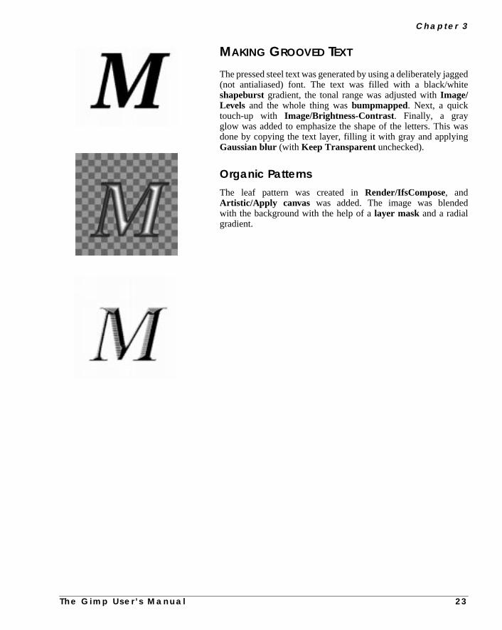
MAKING GROOVED TEXT
The pressed steel text was generated by using a deliberately jag(not antialiased) font. The text was filled with a black/whitshapeburst gradient, the tonal range was adjusted withImage/Levels and the whole thing wasbumpmapped. Next, a quicktouch-up with Image/Brightness-Contrast. Finally, a grayglow was added to emphasize the shape of the letters. Thisdone by copying the text layer, filling it with gray and applyingGaussian blur (with Keep Transparent unchecked).
Organic PatternsThe leaf pattern was created inRender/IfsCompose, andArtistic/Apply canvas was added. The image was blendewith the background with the help of alayer mask and a radialgradient.
T h e G i m p U s e r ’ s M a n u a l 2 3

D o n ’ t U n d e r e s t i m a t e T h e Powe r O f G i m p . . .
you’re
HANDLING GLASS, WATER AND REFLECTIONS
Glass and water effects are usually among the hardest things to create, but with a little help from Gimp,halfway there.
2 4 T h e G i m p U s e r ’ s M a n u a l

C h a p t e r 3
I
l
I
s-d
ple
es
e
e
lic
THE WET LOOK
Adding WaterFor the wet UNIX label, I used a photo ofwaterdrops on a solid blue background.desaturated it and made a duplicate tocreate ahighlight and a shadow layer.This was achieved by adjusting the tonarange with Image/Levels. To create theillusion of water, I needed to displace thebackground where the drops were, soopened a newChanneland painted a maskfor the drops. The channel selection waloaded on a black layer, which I called Displace layer, and the drop shapes were fillewith a black-and-white shapeburstgradient.
Making RainI used a nice, clean photo of a mountain toas a background image, and added a littfog with an FG to Transparent gradi-ent. To stylize and add some wetness to thimage, I created a rain layer. This layer wafilled with the custom rain pattern, dark-ened somewhat and set inAdditionMode. A text layer was also added. I thenran theDisplacefilter on the text and themountain background, using the Displaclayer with the drops.
Displacing Along A CurveTo make the label fit the bottle shape, I mada new displacement mapwith the Gra-dient Editor (dark to the left and right andbright in the middle to make a round dis-placement). After displacing the label, thedisplacementmapwasused toaddametalsheen to the label by setting it inOverlayMode. The final adjustments were madewith theTransform/Perspective tool.
T h e G i m p U s e r ’ s M a n u a l 2 5

D o n ’ t U n d e r e s t i m a t e T h e Powe r O f G i m p . . .
er
ores
l
as
pe
d
--
HOW TO EMPTY A BOTTLE
OF WINE
Cloning Away Unwanted PartsThe bottle was made from a photo of a decantfilled with dark red wine. This was a bit trouble-some because I wanted the bottle to be empty,at least filled with some transparent liquid. Thwine glass that was visible behind the bottle waeasilycloned away, but the rest was left alone— most of it would be covered by the labeanyway.
Making A Dark And Bright LayerThe bottle was cut out, rotated and pasted totransparent layer. Highlight and shadow bottlewere created withLevels (but not desaturated),and the highlight bottle was allowed to keequite a large range of shades; otherwise, threflections in the glass would look too hard anunnatural.
Re-creating Missing PartsTo cover the flat and dull-looking part of the bottle (where the wine was) the bottom part was recreated bycloning different parts of the high-light bottle, and this layer was set toScreenMode. The shadow bottle was set toMultiply .
Highlight layer Shadow layer
Re-created bottle Result
2 6 T h e G i m p U s e r ’ s M a n u a l

C h a p t e r 3
s
e
e
y
-
-f
GLASS DISTORTION
The background, a photo of a lake, wablurred to create the illusion of dis-tance, and to keep the focus on thbottle. The highlight bottle was usedtwice as adisplacement mapon thebackground. This would make therocks in the background appear to bdistorted by the bottle’s curved glass.
Rectifying BandingBecause the lake image was originallindexed, the sky looked banded andugly. This was rectified byfeatherselecting the sky, and replacing it with alinear gradient. I also added the sun(complete with lens flare) and a fewclouds.
REFLECTIONS
The water reflection was made by flip-ping the image of the merged bottle to acopy of the lower part of the lake, blur-ring it, adding some ripples withDistort/Ripple and lowering theopacity level. The waterline (wherebottle meets water) was a little trickierand had to be painted by hand in a couple of Overlay layers. Finally, someglittering highlights were created withtheSparkle filter.
A white haze was added to the foreground, and, of course, so were some oLarry Ewing’s adorable Linuxpenguins.
T h e G i m p U s e r ’ s M a n u a l 2 7

D o n ’ t U n d e r e s t i m a t e T h e Powe r O f G i m p . . .
n easy
TRANSFORMING A PHOTOGRAPH TO A DRAWING
Because black is transparent inScreen Mode(also Addition and Lighten Only ), black pencil strokesdrawn on a white layer will reveal the image underneath, just as if you had sketched it by hand. This is away of creating convincing pencil/ink “drawings” from a scanned photo.
2 8 T h e G i m p U s e r ’ s M a n u a l

C h a p t e r 3
uality. One
eg the
ject.very
MANAGING WITHOUT ARTISTIC PLUG-INS
Several commercial plug-ins, with names likeCharcoal, Crayonor Ink Drawing,can produce similar artisticoutput, but they never come close to the results you can get using the following method. Naturally, the qof the final image depends a lot on the drawing in the screen layer, so this isn’t an “instant artist” trickway of improving coarse computer drawings is to use theValue Propagatefilter and set it tomore white.You can also create a crayon or charcoal look to an image bydisplacing or warping the pen strokes witha suitable displacement map, or just by using unusualbrushes. We also recommend that you reduce thnumber of shades in the background; otherwise, too much of the underlaying image will show, spoilinillusion.
Instant Cartoon PicturesOf course, a very simple way of creating drawings from scanned photos is to use one of theEdge-Detectfilters. RunningSobelon a duplicate results in a transparent layer with a black outline of the image obHaving done this, it’s easy to paint the underlying layer in large, clean areas, and you’ll get somethingsimilar to a picture in a comic book.
Top right: Original imageMiddle right: Transparent Sobel outputBottom right: Handpainted background
T h e G i m p U s e r ’ s M a n u a l 2 9
D o n ’ t U n d e r e s t i m a t e T h e Powe r O f G i m p . . .
snet
d
p
al
ad
e
n
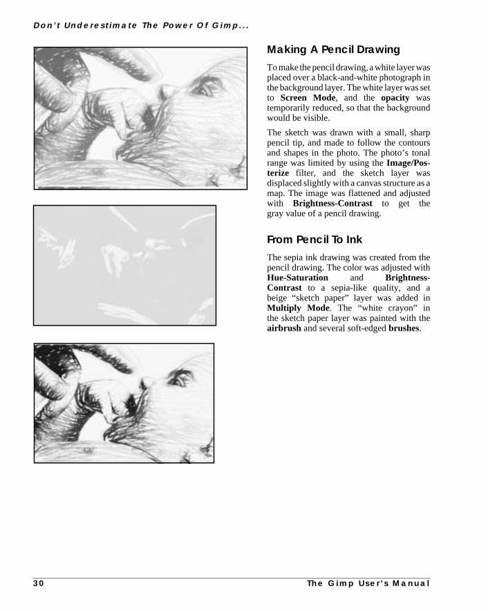
e
Making A Pencil DrawingTomake thepencil drawing,awhite layerwaplaced over a black-and-white photograph ithe background layer. The white layer was sto Screen Mode, and the opacity wastemporarily reduced, so that the backgrounwould be visible.
The sketch was drawn with a small, sharpencil tip, and made to follow the contoursand shapes in the photo. The photo’s tonrange was limited by using theImage/Pos-terize filter, and the sketch layer wasdisplaced slightly with a canvas structure asmap. The image was flattened and adjustewith Brightness-Contrast to get thegray value of a pencil drawing.
From Pencil To InkThe sepia ink drawing was created from thpencil drawing. The color was adjusted withHue-Saturation and Brightness-Contrast to a sepia-like quality, and abeige “sketch paper” layer was added iMultiply Mode . The “white crayon” inthe sketch paper layer was painted with thairbrush and several soft-edgedbrushes.
3 0 T h e G i m p U s e r ’ s M a n u a l

C h a p t e r 3
-
dh
tp
Digital CrayonsFor the crayon drawing, I used coarser, rugged brushes. I also displaced the sketchlayer twice to get the right scratchy crayonor charcoal look. The image was flatteneand the contrast was increased witLevels.
I made a duplicate layer and used theDark1 gradient in the Gradient Editor tomap to the image (Colors/GradientMap). I put the old layer on top, set it toMultiply and erased everything excepthe contours and parts that I wanted to keedark (like the baby’s eye and ear).
In the top layer I placed the posterizedphoto as Darken Only, changed thecolor to violet and applied some motionblur. The result looks a bit like watercolor,but only if it’s used in small areas of a com-posite image.
T h e G i m p U s e r ’ s M a n u a l 3 1
D o n ’ t U n d e r e s t i m a t e T h e Powe r O f G i m p . . .
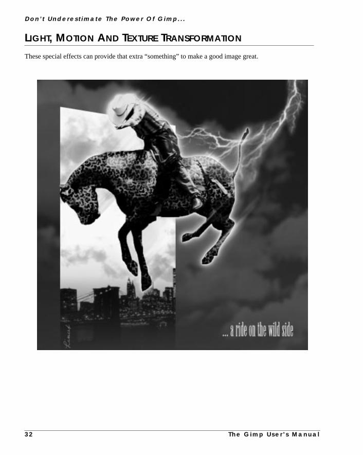
LIGHT, MOTION AND TEXTURE TRANSFORMATION
These special effects can provide that extra “something” to make a good image great.
3 2 T h e G i m p U s e r ’ s M a n u a l

T h e G i m p U s e r ’ s M a n u a l
C h a p t e r 3
of
w
ng arseere
therd
ndset
ee,”ck-
ofend
Shadow layer Highlight layer
AN ELECTRIC HORSEMAN
To create the Electric Horseman, I started out with a photoa rodeo rider. The horse and rider were selected with theBez-ier select tool and pasted to a transparent layer in a neimage. The horse’s halter, mane and tail were eitherclonedaway or erased, and the rider was selected separately (usilittle feather) and saved as a copy in another layer. The hoand rider layer was duplicated twice, and those copies wdesaturated and adjusted withLevels to create highlight/shadow layers.
Using A Cow To Make A Leopard OfA Horse...To create the leopard skin, two more copies were made. Infirst copy, the entire horse shape was filled with the Leopapattern from thePatterns dialog box. Since this pattern isn’tentirely seamless, it was adjusted by painting yellow ablack spots along the visible joints. The leopard layer wasin Darken Only Mode over the second copy, which wasfilled with a yellow-orange gradient to add color depth to thleopard skin. To add some extra glow to the “leopard horsone more texture layer was added. This time I used the blaand-white cow pattern, and set it toOverlay. Note that thisdoes not make the horse look like a cow (!). InOverlay, thelarge dark spots on a white background give the illusionpowerful muscles under a shiny coat. Now I turned to thlayer with the rider, and changed saturation, brightness acontrast to make it fit the new “horse.”
3 3

D o n ’ t U n d e r e s t i m a t e T h e Powe r O f G i m p . . .
h time
Making Things GlowThe glow layer was made by filling a feathered horse and rider selection with red, yellow and white, eacwith lower feather values, and setting the layer toScreen Mode.
3 4 T h e G i m p U s e r ’ s M a n u a l

C h a p t e r 3
seennt
ed
ese
ano
geer.k
ityky
ysendth
Adding MotionThe illusion of movement was more complicated, becaujust adding some motion blur wouldn’t suffice to create thsubtle effect I wanted. I had to create two different motiolayers — one dark and one light. For the dark movemelayer, Blur/Motion Blur was applied to a copy of thecow glow layer. I then did the same for a copy of the oranggradient layer, but this time I inverted the selection, anonly the blurred parts outside of the horse were used. Thlayers were merged after adjusting theopacity. The darkmovement was still a bit too strong in some parts, solayer mask was used to tone down or remove motioglow where it wasn’t wanted. This layer was set tDarken Only. For the light movement layer, I blurredthe shadow layer and the leopard layer (as with the orangradient layer before), merged it and adjusted it to darkTo protect the rider figure from too much blur, a layer maswas used here as well. This layer was set toScreenMode.
Adding SceneryThe background was made of a photo of a blue sky, a cpanorama by night and a yellow evening sky. The blue simage was transformed to dark clouds withImage/Hue-Saturation, and the yellow sky was merged to the citpanorama. The flash of lightning was a bit harder, becauthe only lightning image I had was the Lightning pattern ithePattern dialog, and that was too repetitive to be usedirectly. The problem was solved by scaling an image withe lightning pattern and using theMap/Fractal Traceplug-in. From that image I couldfeather select a suitablepart, and adjust it withTransform/Perspective andScreen Mode to look the way I wanted.
Dark movement layer
Light movement layer
T h e G i m p U s e r ’ s M a n u a l 3 5

D o n ’ t U n d e r e s t i m a t e T h e Powe r O f G i m p . . .
use dif-
MAKING A MONTAGE
There are many ways of blending images, but for advanced montages, the most versatile method is toferent layer masks.
3 6 T h e G i m p U s e r ’ s M a n u a l

T h e G i m p U s e r ’ s
C h a p t e r 3
ssis
to
This
wasar (Ithe
de a
wellth.
THE BACKGROUND
For the Chevelle montage, I used a drawing from the 1966 Chevrolet ChaService Manual for background. To make it less dominant, it wasinverted,blurred andnoisewas added. The color and brightness were changeda soft “old looking” sepia tone.
THE VIGNETTE
The main collage element was a snapshot of me and our Chevelle.image was blended to the background with the help of alayer mask. Istarted by making a round vignette shape with aradial gradient . Thismasked out nice and soft, but it also meant that the gradual transparencyevenly distributed. To put an emphasis on the person rather than the clike to keep it that way) some of the mask was painted white to protectface and especially the arms from transparency.
The vignette was still a little weak, and too smooth at the edges, so I maduplicate where the layer mask was brightened up withLevels, and noisewas added to the mask (not the image). This made the top layer blendwith the spotted background, as well as with the smooth copy undernea
M a n u a l 3 7

D o n ’ t U n d e r e s t i m a t e T h e Powe r O f G i m p . . .
andround.
, so no
illusion
sition,
ADDING NOISE
The next element in the montage was a picture of the fuel pump assembly. Here,noisewas added tobothmask and image. Theglow maskwas made with a feathered lasso selection which was filled with blackheavily blurred before applying the noise. Finally, the image was tinted with the same tone as the backg
MAKING AN ELEMENT STAND OUT IN A COMPOSITION
The steering wheel was treated in a similar manner, only this image was taken from an old magazinenoise was added (it was already quite noisy).
The picture of the car (from a 1966 Chevrolet dealer catalog) was desaturated and tinted. To create theof speed,linear motion blur was applied to an inverted selection of the car, then a simplelayer maskwas added to blend the car with the background. To make the car stand out more in the overall compocontrast andbrightnessvalues were increased.
Two photographs from the service manual were then pasted to a layer with lowopacity.
3 8 T h e G i m p U s e r ’ s M a n u a l

T h e G i m p U s e
C h a p t e r 3
lle”libu”ibund
ADDING DEPTH TO TEXT LAYERS
To make the Chevelle Malibu SS text, I used three different layers. The “Chevelayer is supposed to be sharp and look close to the observer, whereas the “Malayer is further away from focus. This was accomplished by placing the Mallayer very close to (almost under) the Chevelle layer, tinting and blurring it aplacing a very soft shadow on top of it.
r ’ s M a n u a l 3 9


P A R T
II Gimp Installation• OBTAINING AND INSTALLING GIMP
• MIGRATING FROM PHOTOSHOP


C H A P T E R
4 Obtaining And Installing GimpIn this chapter, we will tell you how to obtain a copyof Gimp, and how to install it.

O b t a i n i n g A n d I n s t a l l i n g G i m p
nl.illfullour
willter.
HOW TO INSTALL GIMP PERSONAL FILES
Most Linux distributions include Gimp. But if Gimp isn’t already installed, it camost likely be installed by your Linux distribution application’s installation tooHowever, if you are working on, for example, an SGI workstation, Gimp wprobably not be installed. Please read “Obtaining Gimp” on page 48 to get aexplanation on how to install Gimp both as a binary and as a source on ysystem.
At the command prompt, type “gimp ” and press Enter. If you’ve never usedGimp before, it will display theGimp Installation dialog (as shown), whichtells you that it will install some personal Gimp files in your home directory.
The dialog box also describes the Gimp license and what kinds of files Gimpinstall. It’s advisable to read it, but we will discuss these topics later in this chapIf you want to run Gimp, press theInstall button now!
Figure 4.1 The Gimp Installation dialog
4 4 T h e G i m p U s e r ’ s M a n u a l

C h a p t e r 4
ndto anno
nts
tor.
Thes.
lash
to
n
edi-
After a short delay, you will see theInstallation Log dialog box, informing youthat all files were successfully installed.
A nice feature of UNIX is that programs often store personal initialization files amodules in your home directory. Then, you can change and add featuresapplication without having to modify the application at a system level. Gimp isexception.
Unfortunately, most UNIX programs do not have a GUI for making adjustmeto these files and modules. Here, thankfully, Gimpis an exception, because itincludes a GUI for adjustinguser-definedfunctions. However, there are somespecial functions (i.e., plug-ins) that you’ll have to edit using a regular text edi
After the file installation, you’ll see a splash screen, along with a progress bar.progress bar shows Gimp loading all its extensions, data and certain plug-in
GIMP IN 256 COLORS (USING AN 8 BIT DISPLAY)
Does your 8 bit X11 system cause Gimp to crash just after displaying the spscreen? If it does, you’ll need to configure Gimp to use aprivate color map.Using a private color map, you’ll see color flashing as you move from windowwindow, but at least all possible colors will be available to Gimp.
To make Gimp use a private color map, you need to edit thegimprc file by hand(since Gimp won’t start, you can’t use Gimp’s GUI). You’ll have to do it in axterm window (a terminal, console, etc.). Type in the command:
vi ~/.gimp/gimprc
This command starts the vi editor (however, you’re welcome to use whatevertor you prefer). Move to the line# (install-colormap ) by pressing the j keyseveral times. When your cursor is placed over the# sign at the beginning of theline, press the x key and the # sign will be erased. Now type:
:wq!
Figure 4.2 TheGimp InstallationLog dialog
T h e G i m p U s e r ’ s M a n u a l 4 5

O b t a i n i n g A n d I n s t a l l i n g G i m p
in
ouyre-
.
ndOur
met
ee
,e
x is
This command will both save and exit the file. Gimp is now configured to workan 8 bit display environment, and will not crash.
We would like to point out that if your system can only display 256 colors, ywill never be able to access the full power of Gimp. Gimp will simply not displathe colors as they would appear with 16 bit (or higher) color resolution. We thefore strongly suggest that you upgrade your graphic device to at least 16 bit
ADVICE ON SYSTEM RESOURCES
Since we only use Intel and SPARC hardware platforms running Linux aSolaris, we can only give advice on these platforms and operating systems.advice is also subjective, because it is whatweconsider to be the minimum or therecommended hardware for running Gimp.
On a Linux Intel platform:
• Minimum: Pentium 75, 32 MB RAM
• Recommended: Pentium 200, 64 MB RAM
Solaris Sparc platform:
• Minimum: SparcClassic, 32 MB RAM
• Recommended: Sparcstation 5 110 MHz, 96 MB RAM
Graphic device:
• Minimum: Frame buffer capable of 16 bit color at 800x600
• Recommended: Frame buffer capable of 24 bit color at 1024x768
WHAT ARE ALL THESE FILES USED FOR?
Now, let’s examine the files and directories that Gimp installed in your hodirectory. Gimp created the .gimp directory for its files.The dot indicates tha.gimp is a hidden directory, and you have to use thels -a command (as opposedto just ls ) in a terminal window to see it. In this directory, Gimp created thrfiles: gimprc , gtkrc and pluginrc , along with subdirectories calledbrushes , gradients , palettes , patterns , plug-ins , scripts ,gfig , gflares andtmp . So, what are all these files for?
• gimprc andgtkrc are your personal settings files for Gimp and GTK+respectively (GTK+ is Gimp’s GUI toolkit). Most of the settings in thesfiles are adjustable via thePreferencesdialog box in Gimp, but some ofthem are not and must be edited by hand. The Preferences dialog bodiscussed in “Gimp Preferences” on page 100.
• pluginrc is a file that Gimp needs to store settings about plug-ins,scripts and other external programs.You should not edit or change thisfile, but you may erase it if Gimp starts complaining about it.
4 6 T h e G i m p U s e r ’ s M a n u a l

C h a p t e r 4
y
nd
lin
,
.
he
as
letten
g
e to
or
dg
ean
ee
th
e
on,e to
• Thebrushes subdirectory is where you can store your own personallcreated brushes. You will learn how to create and install brushes in“Brushes” on page 172. Once you’ve installed one or more brushes (ahave refreshed theBrushes dialog box) your personal brushes will showup in Gimp alongside the system-wide brushes.
• Thepatterns subdirectory is where you can store your own personapatterns. You will learn more about how to create and install patterns “Patterns” on page 173. Like personal brushes, personal patterns willappear alongside the system-wide patterns after you’ve installed themand have refreshed the Patternsdialog box.
• Thegradients subdirectory is for storing your own personal gradientsYou will learn more about how to create and install gradients in “TheGradient Editor” on page 177. Your personal gradients will show up in tGradient Editor after refreshing theGradients dialog box.
• Thepalettes subdirectory holds your own personal palettes as wellsystem palettes that you have edited. If you want your system defaultpalette back, you have to rename or erase the copy in your personal padirectory. You will learn about creating, editing and installing palettes i“Palettes” on page 176. The new palettes will show up in thePalettesdialogafter you quit and restart Gimp.
• Theswap subdirectory stores the cache of the images you are workinon. Gimp needs this cache in order to support theUndo capability, and tomake it possible to edit large images without consuming too muchmemory. If Gimp crashes, or something else happens, you may be ablfind a copy of your image in this subdirectory.
• Theplug-ins subdirectory holds any plug-ins that you have createddownloaded off the Internet. New plug-ins show up thenext time you startGimp. You will learn more about plug-ins in Chapters 23 through 39, anin “Compiling Plug-ins” on page 769, we provide a few tips on compilinplug-ins.
• Thescripts subdirectory holds any personal Script-Fus that you havcreated or downloaded off the Internet. The scripts will show up after Xtns|Script-Fu|Refresh command. You will learn about Script-Fus in “Script-Fu: Description And Function” on page 687, and in “MikTerry’s Black Belt School Of Script-Fu” on page 697, you will find somtips on making your own Script-Fus.
• Thegfig subdirectory holds your personal Gfig drawings (created witheGfig plug-in). You will learn about Gfig in “Gfig” on page 600.
• Thegflare subdirectory holds your personal Gflares (created with thGflare plug-in). You will learn more about Gflare in “Gflare” on page519.
The nice thing about all this is that if you find any new plug-ins, scripts and soyou can easily install them in your personal Gimp directories, and don’t havbeg your system administrator to install them for you.
T h e G i m p U s e r ’ s M a n u a l 4 7

O b t a i n i n g A n d I n s t a l l i n g G i m p
s andhy;
t
non
load
it
ad
ifP”
dis-onts
withow-haveder
n-
We encourage you to create your own brushes, palettes, gradients, plug-inScript-Fus, and to share them with the whole Gimp community. Don’t be seven small contributions are welcome.
You can upload them toftp.gimp.org or to thePlug-in Registry athttp://registry.gimp.org . May the spirit of free software be with you!
OBTAINING GIMP
Gimp version 1.0 was released as asource distribution, but for some popularsystems there may bebinary distributions . To get the source code, FTP toftp.gimp.org . The source code is in the directory/pub/gimp/v1.x/v1.0.X. 1.0.X indicates the version, andyou should always get the latesversion.
The directory/pub/gimp/fonts includes some nice free fonts that you cause with Gimp (see “How To Get Fonts To Gimp” on page 759 for instructionshow to install them). The directory/pub/gimp/libs includes some of thelibraries that enable some of Gimp’s optional features, such as the ability toand save JPEG images. The directory/pub/gimp/contrib contains somenice palettes, gradients, etc. If a binary distribution of Gimp exists, you’ll findunder/pub/gimp/binary .
If you are not familiar with FTP, you can use your Web browser to downloGimp, just type the URLftp://ftp.gimp.org/pub/gimp and go onfrom there. Realize that the Gimp FTP site is often heavily trafficked, andftp.gimp.org isn’t near you, we suggest that you use a mirror site (see “FTon page 880 orhttp://www.gimp.org for the nearest mirror sites).
INSTALLING A SOURCE DISTRIBUTION
If you downloaded a source distribution, you should now have a file calledgimp-1.0.X.tar.gz or a file calledgimp-1.0.x.tar.bz2 . (For binary distri-butions, see the next section.) If you want to, you can always get the extra datatribution as well as the unstable plug-in distribution (in the old Gimp distributidirectory). Thedata distribution includes optional palettes, patterns, gradienand brushes that you may find useful. Theunstable plug-in distribution con-tains some plug-ins that weren’t considered stable enough to be releasedGimp 1.0, so remember that they may be unstable and difficult to compile. (Hever, we have used many of them with success here at Frozenriver, and theyalso been documented in the manual.) You will find the unstable plug-ins unftp.gimp.org/pub/gimp/v1.0/old/v1.0.0 .
To unpack the archive, move to the directory containing the Gimp file you dowloaded and type in the following command:
zcat gimp-1.0.X.tar.gz | tar -xvf
This command creates a subdirectory in your current directory calledgimp .Change to thegimp directory by typingcd gimp .
4 8 T h e G i m p U s e r ’ s M a n u a l

C h a p t e r 4
ro-
ft or
our
t in
ts
th.
th.
ndble
filesryre that
Which Libraries Does Gimp Need?If you don’t have them already, you need to get the following libraries or pgrams:
• GTK + (1.0.x), tocompile Gimp. You need this library because all ofGimp’s GUI and functions are built on top of it.
• GNU GhostScript, to enable PostScript file viewing and editing. Typegs -v to output the current version of your GhostScript distribution. Iyou receive an error message, either you have not installed GhostScripit is not in your path.
• Aladdin GhostScript (version 5.50 or higher), to enable good PDF(also known as Acrobat) file viewing and editing. Typegs -v to outputthe current version of your GhostScript distribution. If you receive anerror message, either you have not installed GhostScript or it is not in ypath. (Aladdin is an earlier version of the GNU GhostScript.)
• GNU wget, for downloading files off the Internet directly into Gimp. Tocheck whether you have wget, typewget into a terminal window. If youreceive an error message, either you have not installed wget or it is noyour path.
• xv, if you want to useGuash. Guash is a Gimp plug-in with a GUIinterface for browsing and opening images. Guash uses xv to create ithumbnail images.
• gzip, to enable extra file compression/decompression of any imageformat. To check whether you have gzip, typegzip -h . If you get anerror message, either you have not installed gzip or it is not in your pa
• bzip, to enable extra file compression/decompression of any imageformat. To check whether you have bzip, typebzip -h . If you receive anerror message, either you have not installed bzip or it is not in your pa
• SANE, if you want to scanimages directly into Gimp.
• libtiff , to enable reading and writing of TIFF images.
• libz, to enable PNG compression.
• libpng, to enable reading and writing of PNG images.
• libjpeg, to enable reading and writing of JPEG images.
• libmpeg, to enable reading of MPEG movies.
To determine whether you have these libraries, look in/usr/lib or /usr/local/lib , or contact your system administrator. Most of the programs alibraries come as standard with most Linux distributions, with the possiexceptions of GTK+, Aladdin GhostScript, SANE, wget and bzip.
Remember that even if you have the libraries you must also have the headerto compile Gimp. It’s very common to divide, say, a libtiff package into a librapackage and a header package (development package). So please make suyou have the header (development) package installed.
T h e G i m p U s e r ’ s M a n u a l 4 9

O b t a i n i n g A n d I n s t a l l i n g G i m p
s.
ile.Ifor
ing
in
tall
,
nede
how
Let’s Begin To Build GimpFirst of all, fire up anew xterm window using your window manager or via thecommand:
xterm -sl 200 -sb &
In the new xterm window, move to the directory where you put the Gimp fileThen, type in the command:
./configure
This command will try to locate the files that Gimp needs in order to compNow, scroll up and find out if the configure program could find all of the files.not, you will have to tell the configure program where to find the missing files. Fexample, if your system couldn’t locate thelibtiff andlibjpeg files, youcan do this by adding the followingadditions to the command-line:
--with-libtiff=<path to your tiff library>
--with-libjpeg=<path to your jpeg library>
--disable-debug
(If you are a user and not a developer, you want to turn off debugging. Debuggis turned off by default).
So, the command line might look something like this:
./configure --disable-debug --with-libtif=/usr/local/lib/tiff/
After the configure command has properly executed, you’ll need to typethe command:
make
makewill build your Gimp application. (If you’re having problems, you will findmore information on compiling in “Compiling Plug-ins” on page 769.)
If there were no errors, Gimp built successfully, and you can install it. To insGimp, enter the command:
make install
make install will, by default, install Gimp in /usr/local/bin , the Gimpplug-ins in /usr/local/lib/gimp/1.0 and shared data like scriptsbrushes and configurations in the/usr/local/share/gimp/ directory.
You are allowed to install Gimp in directories other than the ones mentioabove. To do so, read theINSTALL file and use the specified command-linoptions for the configuration program (in particular,--prefix ).
Once you’re done, go back to the first section in this chapter and read aboutto install yourpersonal Gimp files.
5 0 T h e G i m p U s e r ’ s M a n u a l

C h a p t e r 4
imp
ed
tallstaller-
lled
Get
is-
bleklug-tri-in
p.
INSTALLING A BINARY DISTRIBUTION
First of all, get the latestbinary distribution for your system — download itfrom the Gimp FTP site or a mirror site. If you are working on aRed Hat Linuxor Debiansystem, download the packages appropriate for your system (.rpm and.deb respectively); otherwise, download an ordinarytar.gz archive andunpack it into the correct directory (usually /) using the command:
gzip -dc xxxx.tar.gz | tar xvf
Make sure that Gimp is in your path and execute it (type ingimp and see if itworks). Then, go back to the beginning of the chapter, to where personal Gfiles are discussed.
If you have bought the printed version of this book, you will find an enclosGimp CD-ROM compiled for Linux and Solaris systems.
INSTALLING EXTRA PACKAGES TO EXTEND GIMP
To install theextra data distribution you only have to download it. Unpackit, run the configure script and do amake install .
You may also consider downloading and installing the contrib archive, to insmore brushes, gradients, etc. You only have to download it, unpack it and inthe contents in the right directory. You can install new brushes either in your psonal brush directory (~/.gimp/brushes ) or in the system-wide directory(usr/local/share/gimp/brushes ). Some of the contribution archivescome with configure scripts; if that is the case, you install them as you instaGimp. Since it is only data, it should be quite simple. Just type:
./configure && make install
Most of the time this will install the data distributions correctly.
It’s a good idea to download thefreefont andsharefont archives, so youcan get some more fonts for Gimp. Read about how to install them in “How ToFonts To Gimp” on page 759.
EXTRA PLUG-INS
Many of the plug-ins described in GUM are not found in the standard Gimp dtribution. They are either in thegimp-plug-ins-unstable distribution or atthe plug-in registry (http://registry.gimp.org ).
We don’t want to recommend that you download all of the extra plug-ins availafor Gimp (they are quite numerous). If you don’t, you will most probably lacsome of the filters described in the manual, or have an older version of the pin. Most of the time you have to compile these plug-ins by hand; no binary disbution or configure scripts are available. But if you find an interesting plug-inthis book that you don’t have, don’t hesitate to download it and install it.
On the other hand, when you installed Gimp, a second program calledgimptoolwas also installed. Gimptool makes it easy for you to compile plug-ins for Gim
T h e G i m p U s e r ’ s M a n u a l 5 1

O b t a i n i n g A n d I n s t a l l i n g G i m p
p-is
nd
table,elter-
Read more about gimptool in “Compiling Plug-ins” on page 769 and “The gimtool Man Page” on page 804. So, if you don’t have a plug-in (or a filter) thatdescribed in the GUM and you would like to get it, you’ll need to download acompile it.
Note that many of the plug-ins are beta software and can be considered unsbut most of them are (as usual in the UNIX world) of very high quality, and whave encountered very few problems (compared to the bugs in commercial anatives).
5 2 T h e G i m p U s e r ’ s M a n u a l


C H A P T E R
5 Gimp For Photoshop UsersThis chapter is for experienced graphic artists andPhotoshop users who want to learn how to use Gimpwithout having to go through the basics of imagemanipulation. We’ll explain why you want Gimpwhen you have Photoshop. We’ll also try to point outthe differences between Gimp and Photoshop sothat you can get started right away.

G i m p F o r P h o t o s h o p U s e r s
es toplysev-sons
implieve,een
icturenotstan-
rkedtru-
ven
andwhy
s
are
n a
.
ill,ind-ign-er.an
WHY SHOULD I USE GIMP WHEN I HAVE PHOTOSHOP?Perhaps you reckon that you already have the best of the best when it comimage editing programs. In our view, you don’t have the best of the best, simbecause there is no single image editing program that is “the” best. There areeral reasons why you should migrate to Gimp, and there are also some reawhy you shouldn’t. First, we’ll describe Gimp’s strengths.
Gimp has nearly all the functionality that Photoshop has. In certain areas, Ghas more capacity, and in some areas less. Contrary to what many people beGimp is not just another Photoshop clone. Even if there are likenesses betwGimp and Photoshop, many other programs such as Paintshop Pro, X-res, PPublisher and Photo Paint also have their fair share of such similarities. This issurprising, because Photoshop and its user interface is more or less a de factodard when it comes to image editing programs.
Of all the image manipulation programs for advanced users that we have wowith, we have found Gimp to be one of the most versatile and powerful insments available.
GIMP IS FREE
Gimp is a free program, and it can be downloaded from the Internet. But emore importantly, it’s not freeware. Gimp is anOSS(Open Source Software)program covered by the GPL license, which gives you the freedom to accessalso to change the source code that makes up the program. This is how andGimp is constantly being developed and improved.
GIMP HAS A LOT OF GREAT PLUG-INS AND SPECIAL
FUNCTIONS
• Gimp comes with more than 220 plug-ins, some with very advancedfunctions. Practically all of the usual plug-ins that you can purchase aaccessories to Photoshop are already there in Gimp, or they can bedownloaded fromhttp://registry.gimp.org at no cost.
• Gimp’s plug-ins are often much more powerful than Photoshop’s. We not saying that all Gimp filters will produce better results. But if youcompare them to plug-ins that are supposed to do the same thing, theGimp filter is usually a more fine-tuned instrument that will supply theuser with a large number of parameters.
This is for better or for worse, depending on what kind of user you arePhotoshop filters are often of the“press OK and get an instant effect”type. They are more static, and provide the artist with less choices. StPhotoshop filter effects are generally very well chosen. Settings are mful, and the effect they yield is extremely useful for many standard assments in graphic design. In short, it is hard to fail with a Photoshop filtGimp filters on the other hand are more unpredictable in the hands of
5 6 T h e G i m p U s e r ’ s M a n u a l

C h a p t e r 5
me-pa-
as.atess
leee
srn,
seded
l.
asee
is
inexperienced artist just because they offer such a wide range of paraters and settings. However, for an advanced user, they provide an incomrable artistic freedom.
• Gimp has predominantly been targeting web design, and comes with variety of tools designed for creating electronically distributed graphicMost of these tools are not available with Photoshop, which means thyou have to invest in a number of additional programs to be able to accthese features.
GIMP HAS AN INNOVATIVE AND INTUITIVE STRUCTURE
• Gimp has a much smarter menu system that is far more efficient thanthe one present in Photoshop, or for that matter in all other imagemanipulation programs that we know of.
• Gimp has a very different outlook on layers, which is much more flexibthan what you will find in Photoshop. Layers in Gimp don’t come in onsize only; you can create layers of different sizes, or Gimp will optimizthe layer size automatically.
• Gimp has a much more intuitive way of dealing with patterns. All patternare displayed in thumbnail format in a pattern dialog. To select a patteyou just press one of the thumbnails, and the chosen pattern can beapplied with the bucket fill or clone tool.
• Gimp is faster than Photoshop when you work with relatively smallimages, such as those targeting web design.
NOTHING BEATS GIMP SCRIPTING
• Gimp has no less than four powerful scripting languages that can be uto create very powerful plug-ins. (Note that in the 220 plug-ins mentionearlier, the numerous scripting plug-ins have not been included.)
• Yes, Photoshop also has certain scripting capabilities, but it doesn’tcompare to the power of an advanced scripting language such as PerWhen it comes to scripting, we don’t think it’s unfair to comparePhotoshop with a little baby and Gimp with a full-grown adult with 30years of working experience. That’s how big the difference is.
• Gimp can be a backend in your web server, serving your web site withstunning graphics.
• Gimp has functions such as revision control, so you can keep track ofchanges made to a file. You can also connect Gimp directly to a databand create a very nice image database. Those functions are among thmore exotic, but they are just some of the things that indicate that thisno ordinary image manipulation program.
T h e G i m p U s e r ’ s M a n u a l 5 7

G i m p F o r P h o t o s h o p U s e r s
r ifthisnou
ges.potress
hasing
can
t of
illsafe
d
icare,
to
e
If you are working with a UNIX version of Photoshop, such as version 3.01, oyou have an older Mac or Windows version of Photoshop, then we could makelist about twice as long. Let’s just say that if you are working with a UNIX versioof PhotoShop, then you shouldn’t contemplate switching to Gimp. Just do it! Ywill still have Photoshop for tasks where Gimp is insufficient.
SO WHAT’S THE DRAWBACK?
Gimp can’t handle anything other than 8 bit RGB, grayscale and indexed imaThat’s the big disadvantage of Gimp. Since Gimp doesn’t support CMYK or scolors such as PANTONE, Gimp can’t compete with Photoshop in the prepfield.
Photoshop has more third-party plug-ins than Gimp. Yes, even though Gimparound 220 real plug-ins at the moment and that number is constantly growwith around one plug-in every two weeks, there are still more plug-ins that youbuy as accessories to Photoshop, and they aren’t available for Gimp.
Photoshop is also more effective (faster) when it comes to big images with a lolayers (images bigger than 500x500 pixels).
CONCLUSION
It is more or less impossible to tell you what you should or shouldn’t do; we walways be wrong in some cases. Still, there are situations where it is relativelyto suggest that you should migrate to Gimp:
• If you work in a UNIX environment and already have Photoshop installeon your workstation, don’t hesitate for a second, switch to Gimp rightaway. You can still work with Photoshop when you need to deal withprepress matters.
• If you are a graphic designer working with web design, then it’s a verygood idea to migrate to Gimp.
• If you’re interested in advanced scripting, and you need to automatecertain functions for your daily work, Gimp is the program for you.
As the authors of this book, we’d like to recommend Gimp for all kinds of graphdesign. Gimp is so powerful and gives you so much more freedom. Therehowever, cases when you should think twice before switching to Gimp:
• If your chief occupation is prepress, then it’s not a good idea to switchGimp. The exception to this rule is if you work with a UNIX version ofPhotoshop. If you work with the UNIX version, then you can create thdesign in Gimp and import the final outcome into Photoshop.
• If you are working with a Mac and don’t want to change operatingsystems, you will not be able to use Gimp.
5 8 T h e G i m p U s e r ’ s M a n u a l

C h a p t e r 5
wewilln of
thenrve
ilesem-SD
weterbe
into inour
tanalshwill
oubt-
n
g
MIGRATING TO GIMP
So, you have decided to switch to Gimp, or at least to try it out. In this section,will try to describe the main differences between Gimp and Photoshop. Weassume that you are fairly well acquainted with a reasonably recent versioPhotoshop.
We will not cover every dissimilarity between Gimp and Photoshop, becausethis chapter would turn into a new book. Look at it as a quick guide that will seas a starting point.
WHAT’S COMPATIBLE?
Gimp can read Photoshop files, so if you have a large image library of PSD fyou need not worry. You can open PSD images in Gimp, but you have to rember that Gimp doesn’t understand CMYK or spot color specifications. The Pfile must be 8 bit grayscale, 8 bit RGB or indexed.
If you are an Adobe Filter Factory fan, and have a lot of Filter Factory filters,have some good news for you. By copying the FF filters to Gimp’s User Fildirectory, they will be available for use in Gimp. Please read “User Filter (AdoFilter Factory Emulator)” on page 507 how to install your filters.
There’s also a file that will make Photoshop shortcut commands availableGimp, so you can control functions with the same shortcuts that you’re usedPhotoshop. You are also free to assign any shortcut key to a function of ychoice, simply by typing the new shortcut beside the function in the menu.
WHERE ARE THE MENUS?
The first time you run Gimp, it will install some personal configuration and dafiles. Just answer OK to those questions (see “How To Install Gimp PersoFiles” on page 44). A moment later Gimp will start by displaying the Gimp splascreen. Then the toolbox, which is quite similar to the one in Photoshop,appear on your desktop.
The questions that every Photoshop user will ask themselves now are undedly: Where are themenusand where is myworking area? There is only a Filemenu and an Xtns menu, and there isn’t much in those menus.
HOW TO GET TO THE MENUS
To access the menus in Gimp you have toopen or create a new image. SelectFile|New to create a new image.
SelectFile|Open to open an existing image file. If your file has a well-knowsuffix, such as tif(f), psd, jp(e)g, etc., then theDetermine File Typemenu shouldbe set toAutomatic. For further information on how to open files, read “OpeninFiles” on page 79.
T h e G i m p U s e r ’ s M a n u a l 5 9

G i m p F o r P h o t o s h o p U s e r s
us!blyve tohisper-
s byright
are
d in
; 72
yedweb.
l of
THE RIGHT MOUSE BUTTON
Press theright mouse buttonin the opened image, and voilà, there are the menIn our opinion, this is one of the best things about Gimp, and you will probaagree with us as soon as you get used to it. In most other programs, you hatravel a long way with the mouse to access the different function menus. Tresults in a constant clicking, dragging and moving the mouse up and down, toform even the simplest task (which is why remembering shortcut commandheart tends to be so important in Photoshop). In Gimp, you simply press themouse button and all the menus are there, close at hand.
WHERE DO I SET RESOLUTION AND CANVAS SIZE?
Resolution In A New ImageLet’s try to make a new image in Gimp withFile|New . In theNew Imagedia-log box, you’ll find that the only available size parameters for the new imagetheWidth and theHeight, and they are measured inpixels. This is quite differentfrom Photoshop, where the Width and Height parameters can be specifieinchesor cm, and you are asked to set theresolution of the image.
Gimp only has one resolution, and that is the most common monitor resolutionppi (pixels per inch). This is also known asweb resolution. Images created inGimp will look the same when they’re open in Gimp as when they are displain a browser such as Netscape, so this is no disadvantage if you design for the
Figure 5.1 Gimp’s menu system is activated by the right mouse button. Justpress the right mouse button in the image, and you have instant access to alGimp’s features.
6 0 T h e G i m p U s e r ’ s M a n u a l

C h a p t e r 5
ndtersres-
ou
ring
thetheare
with
s. A
Since Gimp only displays one resolution, it’s only natural that the width aheight variables are measured in pixels. Fixed units such as inches or millimeare not relevant on a monitor and you can’t make decent printouts from 72 ppiolution, so there is no point in using them when you create your image.
Still, you will need to set the resolution if you want to print your image, and ycan do that from Gimp’sPrint dialog (or from Save As PostScript). How-ever, there is some math involved. For more information, take a look at “PrepaFor The Press” on page 201 for formulas that you can use.
Image Size And Image/ScaleIn Photoshop, you are used to changing the resolution and print size withImage Sizecommand. As we have just explained, in Gimp you can’t changeresolution and print size until you print (to paper or to file), but you can prepyour image for a certain resolution by changing thesize(in pixels) of your image.In Gimp, this function is calledScale (right-click|Image| Scale ).
Canvas Size And Image/ResizeIn Photoshop, the relative size and proportions of an image can be changedCanvas Size. In Gimp, this command is calledResize (right-click|Image| Resize ). This has caused a lot of confusion among Photoshop usercommon mistake is to confuse theImage| Resize command with Photoshop’sImage Size command, because they associate the termsimageandsizewithresolution and not with canvas size.
Figure 5.2 In Gimp you can only set the image sizein pixels, and the resolution is always 72 ppi. If youneed a higher resolution, then you’ll have to make afew calculations.
T h e G i m p U s e r ’ s M a n u a l 6 1

G i m p F o r P h o t o s h o p U s e r s
nvasnot
(seethis
lecify
han
The next thing that will bewilder Photoshop users when they increase the casize is that the background layer (or any of the other layers for that matter) willconform to the new size. The reason for this is that in Gimp, layers can havedif-ferent sizes.
By changing the canvas size, you have specified the new maximal layer size“Layers And Channels” on page 66). If you want any of your layers to assumelayer size you must selectright-click|Layers|<Layers &Channels>| Resize Layer , or invoke the shortcut command Ctrl+R. Alnew layers that you add to your image will assume the new size, unless you spanother size in the New Layer dialog. Also note that Gimp’sResize commandwill allow you to place your image in a more exact position on the new canvas tis possible in Photoshop (Canvas Size ), and that you’ll get a preview of theproportions to help you set the new size and position.
DIALOGS
When you open Photoshop, the Palette windows will appear containing:
• Navigator, Info and Options
• Color, Swatches, Brushes and Actions
• History
• Layers, Channels and Paths.
Figure 5.3 The Image Resize dialog. Noticethat you resize the canvas and not the size ofthe layers because Gimp layers don’t have afixed size.
6 2 T h e G i m p U s e r ’ s M a n u a l

C h a p t e r 5
imp.noin
n’t
list
re
op,
alsodia-
orm,. Thehop,endtton,72.
Gimp also has such dialogs or palettes, but they aren’t open when you start GThey are also arranged a bit differently. Let’s just say that in Gimp there areNavigator, Path, Action or History dialogs. We will, however, discuss Actions“Actions” on page 70.
First of all, you have to open all dialogs in Gimp yourself, because they areopen by default. You will find them underFile|Dialogs and right-click|Dialogs , and there are also other ways to bring them up. Here is aof which is which:
• TheColor Info dialog will pop up when you use the color picker.
• Tool Options is the same as Options in Photoshop.
• To access theColor dialog, you have to double-click on the foregroundor background color swatch in the toolbox.
• Palettes is the same as Swatches.
• Brushes in Gimp equals Brushes in Photoshop.
• Layers and Channels are in the Layers & Channels dialog.
• In Photoshop, you set the gradient type both in the toolbox and in theoption dialog of the Gradient tool. In Gimp you have the same (only moadvanced) possibilities, but theGradient Editor is invoked from theDialogs menu, not from the Tool Options dialog.
• Using Gimp’sPatternsdialog to apply a pattern is much easier than tosearch for pattern libraries in Photoshop.
• If your image is indexed, then you can view and edit all of the indexedcolors in theIndexed palette.
BrushesThe Gimp Brush Selection dialog is similar to the Brushes dialog in Photoshbut there are some differences. In Photoshop, there is abrush editing dialog,whereyou can change or create new round or calligraphic brushes. In Gimp you canmake your own brushes, but not as quickly, because there is no brush editinglog. In both Photoshop and Gimp you are quite free to create brushes in any fbut the way brushes are handled in Gimp is much easier than in Photoshopbiggest advantage is Gimp's Brush dialog. If you have a big brush in Photosyou will only see the left top corner, which may be totally white. In Gimp, if thbrush doesn’t fit into the thumbnail image, you can click on the Brush icon, aa life-size image of the brush will pop up. As soon as you release the mouse buthe image will disappear. Read more about brushes in “Brushes” on page 1
T h e G i m p U s e r ’ s M a n u a l 6 3

G i m p F o r P h o t o s h o p U s e r s
imp,
p
thebun-theby
173
PatternsWorking with patterns is much easier under Gimp than under Photoshop. In Gthe currently active pattern is determined by the selected pattern in thePatternSelectiondialog. This pattern is available for all tools that use patterns in Gim(the bucket fill tool and theclone tool). You can apply patterns in differentopacity and modes by setting these parameters in the Bucket Fill dialog or inBrushes dialog. You can also create and save your own patterns (Gimp has adle of excellent tools for making seamless tiles for patterns). When you browsepatterns in the Pattern Selection dialog, you can view the pattern in full scaleclicking on it, just as in the Brushes Selection dialog. Read “Patterns” on pagefor more information on patterns in Gimp.
Figure 5.4 Gimp’s Brush Selectiondialog. As you can see, a Gimp brushcan have any shape. Notice theinstant preview of the brush when youclick on it.
Figure 5.5 The Photoshopbrushes dialog.
Figure 5.6 Gimp’s PatternSelection dialog.Gimp’s way ofdealing withpatterns is easierthan in Photoshop.
6 4
T h e G i m p U s e r ’ s M a n u a l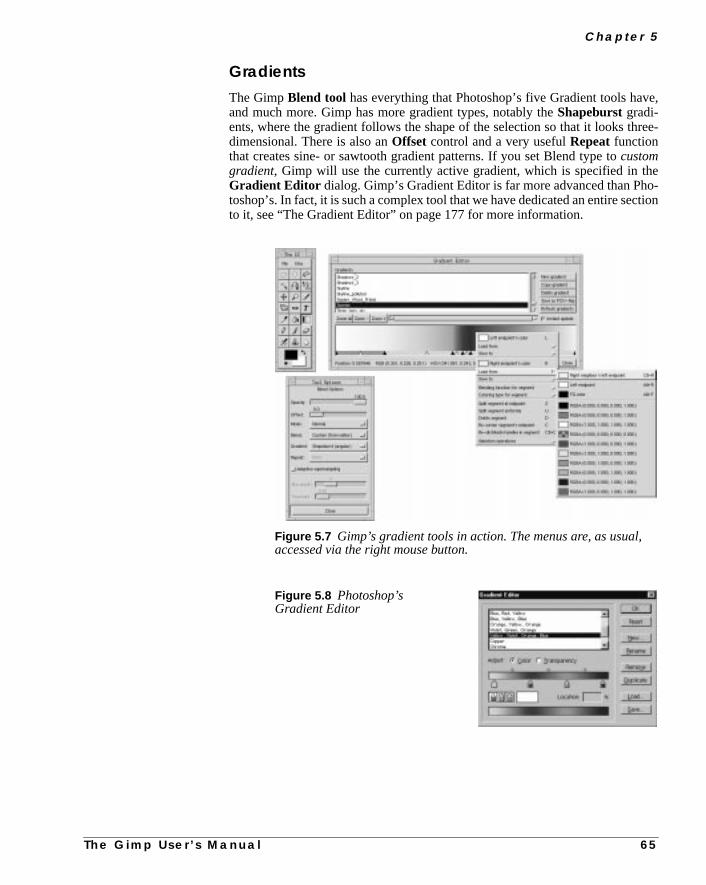
C h a p t e r 5
e,
ree-
eo-
ction
GradientsThe GimpBlend tool has everything that Photoshop’s five Gradient tools havand much more. Gimp has more gradient types, notably theShapeburstgradi-ents, where the gradient follows the shape of the selection so that it looks thdimensional. There is also anOffset control and a very usefulRepeatfunctionthat creates sine- or sawtooth gradient patterns. If you set Blend type tocustomgradient, Gimp will use the currently active gradient, which is specified in thGradient Editor dialog. Gimp’s Gradient Editor is far more advanced than Phtoshop’s. In fact, it is such a complex tool that we have dedicated an entire seto it, see “The Gradient Editor” on page 177 for more information.
Figure 5.7 Gimp’s gradient tools in action. The menus are, as usual,accessed via the right mouse button.
Figure 5.8 Photoshop’sGradient Editor
T h e G i m p U s e r ’ s M a n u a l
6 5
G i m p F o r P h o t o s h o p U s e r s
lenge
the
bigyer315jor
le to
nd
it
ar
ck).
haone
Tool OptionsTool options work just like in Photoshop. However, Gimp doesn’t have multiptoolbox buttons, so you can’t, for example, click on on the Gradient tool to chato another gradient type. Instead, Gimp keeps the tool controls in thetoolboxoption dialog. This means that you will have to change the gradient type inBlend tool’s option dialog instead of pressing another button in the toolbox.
LAYERS AND CHANNELS
The Layers & Channels dialog looks a lot like Photoshop’s, but there are somedifferences. We will discuss Layers and Channels further in “Layers And LaControls” on page 68 and “Layers And Floating Selections” starting on pagewill give you even more information. How layers are handled is one of the madissimilarities between Photoshop and Gimp.
First of all, there is noPath dialog. Gimp does supportpaths(see “Paths” on page68) but only one at a time, and you must store it in an alpha channel to be absave it.
Channels
• There is no support for CMYK or spot color, so only alpha channels aRGB channels are available in the channels tab.
• All RGB channels are displayed incolor in Gimp; for example, if youselect a single color channel, it won’t look like the grayscale thumbnail;will be blue, green or red.
• Split and Merge Channels functions are inright-click|Image|Channel Ops |Compose andDecompose.
• To load the selection from an alpha channel, right-click in that channel band selectChannel to Selection.
• To save a selection in a channel, useright-click|Select| Saveto Channe l.
• Color in a channel always indicates masked areas (default color is bla
• There is no simple way of merging (add, subtract or intersect) two alpchannels to create more advanced selections. To do this you must loadof the channels into another and:
• Fill the selection withwhite to add.
• Fill with black to subtract.
• right-click|Select| Invert and fill with black to intersect.Then, you may load the selection of this new channel as usual.
6 6 T h e G i m p U s e r ’ s M a n u a l

C h a p t e r 5
the
sed
op,wnI
theto say
d tobut
youelec-
lt +lec-
othl be
theherelogi-
illyou
Layers
• Since layers can have different sizes in Gimp, you may want to changelayer’s size and relative position. The commands that will do that arecalledScale Layer andResize Layer, and you’ll find them in theLayers tab’s right-click menu.
• To enable transparency in a solid background layer, alpha must beenabled; selectright-click|Layers| Add Alpha Channel todo so.
• To load layer transparency, select Alpha to Selection in the menu accesby right-clicking in the Layers tab.
• When you move layers or channels up and down the stack in Photoshyou simply drag and drop. In Gimp, you move layers one step up or dowith thearrow buttons. This is one of the rare occasions when Gimp’s Uisn’t as good as Photoshop’s.
SELECTIONS
Selections in Gimp and selections in Photoshop are alike in the idea, but not inimplementation. Therefore, this is one of the areas that Photoshop users tend“%¤#%¤#” since they don’t understand what’s happening.
Moving Selections/Floating SelectionsWhen you make a selection in Photoshop, your Selection tool will be translatea “Move tool” and you can move the selection. The same happens in Gimp,when you move the selection you move thesubstanceof the selection, not theempty selection outline.
If you now (in desperation) use the selection tool again (within the selection)will create a mask, not a real selection. This is because when you moved the stion the first time, you created afloating selection, and when you moved it thesecond time, you created asubselection (a selection in a floating selection).
To use selections as you’re used to in Photoshop (v.5.0) you have to hold Ayour mouse button when you move the selection. You may now move the setion without creating a floating selection. Does it sound complicated? Well, it bis and isn’t. Please read “Moving Selections” on page 112 and everything wilclear.
Selection ControlBasic selection control is nearly the same as in Photoshop, but not exactlysame. Adding to a selection is the same in both Gimp and Photoshop. But wPhotoshop uses Alt to subtract, Gimp uses Ctrl. Intersect is therefore quitecally Ctrl+Shift in Gimp.
However, Shift also controls the shape of your selection. If you press Shift it wa create a square or circular selection, depending on which tool you use. If
T h e G i m p U s e r ’ s M a n u a l 6 7

G i m p F o r P h o t o s h o p U s e r s
k istely
ec-
astion
canbit
onceu canimp,
firstmpcis-wasbe
the
cur-theto
thethey
want a rectangular or an elliptical selection when you add or intersect, the tricto start the selection with Shift pressed down, and then release Shift immediaafter dragging the mouse. For a full understanding of all Gimp tricks with seltions, please read “Selection Control” on page 110.
Quick MaskThere is no quick mask function in Gimp. But quick mask is really the samepainting a mask in a channel. The difference is that you can invoke the selecreally quickly, and also switch to and from mask/selection in an instant. Youachieve the same effect in Gimp (or Photoshop) using channels. It will be aslower, but that’s nothing a good script can’t take care of.
PathsGimp doesn’t have multiple, re-editable paths. Gimp paths can’t be stored, soyou have converted a path to a selection, there is no way back. Of course, youse channels to store the selections. For more information about paths in Gi.e., Bezier selection, read “The Bezier Selection Tool” on page 120.
Magnetic SelectionsGimp’s equivalent is calledIntelligent Scissors, but we must admit that Photo-shop’s tool is much more effective. This is a bit strange because Gimp waswith this feature (Gimp 0.54), well ahead of Photoshop. However, when Gi0.99 arrived, the internal image handling was so different that the Intelligent Ssors feature no longer worked. An experimental version was used instead; itstable but not very efficient. The current rumor is that Intelligent Scissors willin good shape when Gimp 1.2 is released sometime in the future.
Magic WandGimp’s Magic Wand tool is called Fuzzy Select. In the Photoshop tool, you setsensitivity in the Option dialog. With Fuzzy Select you do it this way:
After you position the cursor and press the mouse button, you have to drag thesor (don’t release the mouse button yet) from the upper-left corner, either toright or straight down (that doesn’t matter) to go from a small, stingy selectiona very generous one.
LAYERS AND LAYER CONTROLS
Layers is one of the areas where Gimp differs most from Photoshop — not inessence of basic usage, but Gimp’s layers are much more powerful becausedon’t suffer from the “one size fit all” syndrome.
6 8 T h e G i m p U s e r ’ s M a n u a l

C h a p t e r 5
oube
age
natu-newu’llbigas is
thishasize,
-
ehetingout
ti-impemre
em.ti-ead
e. If
Moving LayersWhen you use theMove tool for the first time, you will probably move thewhole image, which will seem very confusing to a Photoshop user. Actually, ydidn’t move the image, you moved the Background layer. In Gimp, layers canmoved without restrictions, so it’s no problem to move the layer outside the imcanvas. This is a very handy way of moving text in atext layer. Please read “TheMove Tool” on page 156 for more information about moving layers.
Layer SizeSince you can move layers freely, even outside the image canvas, you canrally create layers that are bigger than the image itself. When you create alayer (right mouse button in the Layers dialog), a dialog will appear, where yobe asked to specify the size of the new layer. It’s now up to you to make it asor as small as you want. The fact that the layers can be bigger than the canvused very effectively in a plug-in calledGAP (see “Advanced Animation WithGimp Or How To Use AnimFrames” starting on page 639) where you can usepossibility to effectively panorate the background in an animation. (Yes, Gimpits own animation studio.) For more information about layers and layer splease read “Resize Layer” on page 321.
Layer OptimizingWe were discussingfloating selectionsin an earlier paragraph. Just as in Photoshop, when you create a floating selection you will get a special layer in theLay-ers & Channel dialog. Just double-click on the floating selection bar in thdialog, and Gimp will create an optimized layer from the floating selection. Tnew layer will not be bigger than the selected object that made up the floaselection. Read “Floating Selections” on page 331 for more information abfloating selections.
Layer Alignment And ManipulationGimp’s layer alignment differs from Photoshop’s. Because Gimp works with opmized layer size, you align the layers and not the substance in the layers. Gprovides several ways of layer aligning, rotating, and redistributing. It may seconfusing in the beginning, but once you get to know it you will love it. Read moabout it in “Layer Align, Adjust And Move Operations” on page 326.
You can also bend and otherwise manipulate layers and the objects within thAfter being manipulated, the layer will be resized on the fly to fit its new opmized size. If you want to know more about these special layer functions, r“Transforms” on page 330.
TYPES AND FONTS
There are two ways of handling fonts in Gimp. The first one is theText tool inthe toolbox, which is a rather simple and restricted way to add text to an imag
T h e G i m p U s e r ’ s M a n u a l 6 9

G i m p F o r P h o t o s h o p U s e r s
ryare
hop
itwill
hop.our
CGIcan
fly.
iptsin
le.
s areges.ooGimpow
usee toYK
, buthas ams.uld
you are used to Photoshop’s Text tool, you will probably find this Text tool velimited. This Text tool is useful for simple texts where only a few charactersinvolved.
Relax, there is an advanced Gimp text tool. It is similar to the one in Photos5.0, and you will find it under right-click|Filters|Render|Dynamic Text . Dynamic Text is a very versatile Text tool, and you can edand replace text just as usual. If you are used to Photoshop’s Text tool, youhave no trouble working with Dynamic Text.
ACTIONS
Here is one of many areas where Gimp is a lot more powerful than PhotosGimp supports Script-Fu, Perl-Fu, Tcl-Fu and Python-Fu — no less than ftypes of “actions” languages.
Script-Fu is the current default script language and it is based on Scheme.Perlis the new runner-up. Perl is the de facto standard scripting language forscripts. There are literally thousands of Perl algorithms and functions that youuse for image manipulation in your scripts.
You can even use Gimp as a CGI script, delivering custom graphics on theFurthermore, you can enable image editing from the web with the help ofNet-Fuwhich is a way to access Gimp from a web server.
A lot of Gimp users make scripts, and you can easily download all sorts of scrfrom various web sites. Maybe it’s not that easy to get started with scriptingGimp, but the power it offers is so much stronger that it’s well worth the troubRead “Web” on page 878 for further information reading scripting in Gimp.
PRE-PRESS
In this area, Photoshop is much better than Gimp. Gimp pre-press capabilitievery limited because it can only handle RGB, grayscale and indexed imaWorking with pre-press and Gimp will require some planning, and it’s way tmuch to write about here. We have devoted a whole chapter to pre-press andso please read “Pre-press And Color In Gimp” on page 197 and you will knwhat to do if you are in the pre-press business and still want to use Gimp.
If you already have a UNIX version of Photoshop, we recommend that youGimp until you reach the stage where you would normally convert the imagCMYK. Instead, save the image and switch over to Photoshop to make the CMconversion and other preparations for print.
SOME FINAL NOTES
We have not covered every single difference between Gimp and Photoshopwe have discussed the major ones. You should also keep in mind that Gimplot of functions that aren’t available among the Photoshop stock prograReading this overview will not make you a master of Gimp. This chapter sho
7 0 T h e G i m p U s e r ’ s M a n u a l

C h a p t e r 5
canmp
ourfrom
be seen as a means to help you quickly move over the basics so that youconcentrate on the fun stuff, which is exploring the more advanced Gifunctions.
A migration is never easy, and it will take some time before you are adjusted to ynew favorite. We can only say that we have never regretted that we switchedPhotoshop to Gimp.
T h e G i m p U s e r ’ s M a n u a l 7 1


P A R T
III Basic Functions• FILES AND PREFERENCES
• SELECTIONS
• PAINT
• EDIT
• TRANSFORM
• TEXT
• BRUSHES AND OTHER DIALOGS

C H A P T E R
6 Files And PreferencesIn this chapter, we will discuss how to save, openand create files, and how to set preferences. We willalso cover how to list the file formats supported byGimp and how to print from Gimp.
F i l e s A n d P r e f e r e n c e s
inThe
fors AndFu:
THE FILE MENU
In Gimp, you can get to theFile menu in two different ways: by clicking on theFile command at the top of the toolbox, or by clicking the right mouse buttonan image window and moving your mouse cursor down to the File command.menus are slightly different in the two places; in thetoolboxFile menu, you willfind the following menu items:
• New
• Open
• About...
• Preferences...
• Tip of the day
• Dialogs
• Quit
And in theright-click File menu, you will find:
• New
• Open
• Save
• Save as
• Preferences...
• Close
• Quit
• Mail image
• Onroot
In theXtns menu (in the toolbox), you will find:
• DB Browser
• Guash
• Screen Shot
• Waterselect
• Script-Fu
• Web Browser
With the exception of theDialogs and Script-Fu menu entries, we’ll discussevery entry in these three menus. You will find information on the dialogsBrushes, Gradients, Palettes and Patterns in “Brushes, Gradients, PalettePatterns” starting on page 171. Script-Fu will be discussed in “Script-
7 6 T h e G i m p U s e r ’ s M a n u a l

C h a p t e r 6
lt
rk-
IFho-e.
see
til
theer
n anour
Description And Function” starting on page 687 and in “Mike Terry’s Black BeSchool Of Script-Fu” starting on page 697.
CREATING IMAGES
Let’s start by creating our first image. Click on the Filemenu in the toolbox, and selectNew. This will bring upthe dialog box shown to the right.
The dialog box allows you to decide the size of your imagein pixels, whether your image should be grayscale or RGBand what color it should be filled with, or whether it shouldbe Transparent (alpha-enabled).
As you can see, three solid backgrounds are available:Background, Foreground and White.White will produce awhite background, andBackground will produce a col-ored background based on the background color in the tool-box (more about choosing a color from the toolboxbackground/foreground swatches can be found in “TheColor Selection Dialog” on page 143.) Foreground willcreate a background using the foreground color in the tool-box. Transparent results in a checkerboard-like back-ground that signifies transparency, or the presence of analphachannel (aconvenient feature forcreating transparentGIFs).
For now, let’s stick to the default values; just click on OK. Now you have a wospace to work in. Close the image by choosingright-click|File| Close .Note thatright-click|File| Quit will both close your image and quitGimp.
You may wonder why you can’t create anindexedimage (an image with a small,fixed set of specific colors) right away. After all, it would be great for that nice Gyou’re trying to make for your web site. The reason for this is that you haven’t csen a set of colors, and Gimp can’t predict which colors you’ll use in your imag
It’s almost always a very bad idea to start out with an indexed image.You shouldcreate GIFs by converting your completed image from RGB to indexed (“RGB, Grayscale And Indexed” on page 266). The rule of thumb is: Always workwith RGB (or with whatever color model you need) and don’t convert it unyou’re finished.
GUASH
One of Gimp’s most useful features isGuash. If you have worked on a UNIX sys-tem before, you have probably usedxv and its Visual Schnauzer.Visual Schnau-zer displays thumbnails of images, and allows you to browse throughthumbnails and load images using a graphical interface. Or if you’re a formMacintosh and Photoshop user, and you’re used to the small thumbnails iimage directory, then you’re going to love Guash. Guash lets you browse yhome directory and see all of your images as small thumbnails.
Figure 6.1 TheNew file dialog
T h e G i m p U s e r ’ s M a n u a l 7 7

F i l e s A n d P r e f e r e n c e s
p
criptthe
ny
ore),scanillow.
ange
)
ededlick
To start Guash, select it from the Toolbox menuXtns|Guash . When you firststart Guash, it will scan your home directory, looking for image files that Gimcan read. If it finds aPostScript file, a dialog box will appear in which you canpressLoad to load the image, or selectCancelto skip that file. This is a nice fea-ture, because loading PostScript files can be slow. In addition, because PostSfiles are sometimes very large, they can take up a great deal of space ingimpswap file, the temporary file that Gimp creates when it opens a file.
Tip: Load PostScript files only if you need to, and only load the first page in acase.
Guash’s directory scanning can take quite some time (five minutes or even mdepending on the number of images in the directory being scanned. Once thehas completed, simply double-click on a thumbnail to load it (the first click wselect it; the second opens it), and the image will open in a regular Gimp wind
Guash only displays a set number of directories or images at a time. To chGuash’s default behavior, you need to edit thegimprc file in your .gimp direc-tory. Look for (or add) the following entries:
• guash-ncol “5” changes the number of columns (valid range is4 to 10)
• guash-nrow “3” changes the number of rows (valid range is 2 to 10
• guash-keybindings “emacs” enables Emacs-style key bindings
If you click on a Guash thumbnail, it will become selected and will be highlightwith a red frame. If you click once more on the highlighted image, it will be loadinto Gimp. To select or deselect more images, hold down the Shift key and con their thumbnails.
Figure 6.2 The Guash window
7 8 T h e G i m p U s e r ’ s M a n u a l

C h a p t e r 6
hen
opy-NIXom
o-ited.tooundit for
youd-
If no images are selected, pressing the right mouse button will bring up arootmenu. If any images are selected, a right-click will produce aselect menu,which allows you to perform various operations on the selected images.
All of the items on the menus are easy to use and learn. To get the root menu wimages are selected, hold down Shift and press the right mouse button.
In Guash, you can do all the usual file management sorts of things (moving, cing and deleting images, and creating directories). You can even apply Ucommands and, more importantly, Script-Fu “commands” to your images freither the root or select menu.
TheJump button (at the top-right corner) allows you to quickly change directries. The Jump menu also includes shortcuts to directories you’ve already visYou can also bring up a file dialog, which makes it simple to move quicklyanother directory. We recommend using the Jump menu, because moving arwithin Guash can be quite slow, because Guash scans each directory you visimages.
OPENING FILES
Next, we’ll open an image using File|Open. This will pop up theLoad Imagedialog box, which allows you to browse file names so you can select the imagewant. In theDetermine file type pull-down menu, you can choose what kinof file you want to open, or let Gimp do it automatically (by leaving it at Automatic).
Figure 6.3 The LoadImage dialog
T h e G i m p U s e r ’ s M a n u a l 7 9

F i l e s A n d P r e f e r e n c e s
gally
for-of
rl in
e
theboly to
ew
lick
theare
In general, it’s a good idea to let Gimp figure out the file type. If Gimp is havina hard time with a particular file, then you can step in and lend a hand by manuspecifying the file type.
Familiarize yourself with the interface by opening some images in commonmats like GIF, JPEG and TIFF). Later in this chapter, we’ll discuss what kindformats Gimp can read and write.
Tip: Gimp can automaticallyexpandyour file name, so you only have to enteenough of the name to uniquely identify the file. Then, press the Tab key to filthe rest of the file name, just as you can do in certain UNIX shells.
The Load Image dialog box also allows you to delete (Delete File) and rename(Rename File) files. To do this, simply click on the file to select it and press thcorresponding button. This will bring up aconfirmation dialog box. To createa directory, press theCreate Dir button and a dialog box will prompt you for thename of the directory.
If you’ve just created a new directory (or have made any changes to the files indisplayed directory), remember to double-click on the current directory sym(./ ) to update the file listing; otherwise, you won’t see the changes. The abilitcreate directories in theLoad Image or Save Imagedialogs is actually quitehandy, as you’ll often find you’ll want to save images for a new project in a ndirectory.
OPENING POSTSCRIPT AND PDF FILES
If you select a PostScript or PDF file in the Load Image dialog box, and then con OK, Gimp will pop up aLoad PostScript dialog box, as shown. Our adviceis to not change any values here if you’re going to print it at home or inoffice — the default values are fine when displaying the paper formats thatnormally used for PostScript files.
Figure 6.4 The Load PostScriptdialog
8 0 T h e G i m p U s e r ’ s M a n u a l

C h a p t e r 6
f yourt ofhtted.
r
es
e.
. Offile,
de,
the
age
with-
hichort
she
If you lower theResolution, you’ll also have to reduce theWidth andHeightof the image canvas (and vice versa, if you increase the resolution). Note that idon’t change the width and height when you increase the resolution, only payour PostScript file will be displayed. On the other hand, if the width or heigexceeds the size of your PostScript file, the display will automatically be adjus
If you uncheck thetry BoundingBox checkbox, the pages will be stacked oveeach other; otherwise, they will be displayed side by side. ThePagesentry allowsyou to specify what page or page interval to display; for example,1-99 specifiespages 1 to 99, and75 specifies page 75 (if your PostScript file has fewer pagthan the numbers you specify, the numbers will be adjusted automatically).
Selectingb/w will produce a black-and-white image from a color PostScript filGray or color will produce a grayscale or a colored image, respectively.Auto-matic will produce whatever type of image the PostScript file was created ascourse, you can’t obtain a colored image from a black-and-white PostScripteven if you select color. Gimp is good, but it’s not that good!
You can also specify the level ofantialiasing for text and graphics. If you onlywant a quick look at your file, then selectnone or weak. On the other hand, ifyou’re done working on the file and you’re going to press, then selectstrong.
SAVING IMAGES
Gimp lets you save the images you’ve created. Isn’t that wonderful? Afree pro-gram with save abilities! Compare this to using Photoshop for free in demo mowhere “save and print are disabled, this is a demo copy.”
You can access theSave Image dialogby pressing the right mouse button inthe window that contains the image you want to save:right-click|File|Save As . The Save Image dialog is exactly the same as theLoad Image dialog,except that the Determine file type menu is a bit different. In this context,default is By extension.
By extensionmeans that the format of the resulting image depends on the imfile’s extension. For example, if you name your imagehello.gif , it will auto-matically be saved in GIF format. You can of course choose to savehello.gifin TIFF format, by selecting TIFF in theDetermine file type menu, but this isnot a good idea, because it tends to confuse people. If you want to save a fileout an extension, then youmust choose the file type from the menu.
Note: Remember toflatten the layers in your imagebefore you save it, unlessyou are saving inXCF format (Gimp’s native file format) or creating aGIF ani-mation.
Gimp supports many different file formats; the exact number depends on wplug-ins you have installed. Yes, as with most things in Gimp, file format suppis implemented withplug-ins. Examples of plug-ins are themail and printplug-ins, and all of thefilters. We will discuss plug-ins in general later on in thibook. Right now, we will concentrate on the file format plug-ins included in tbase Gimp distribution.
T h e G i m p U s e r ’ s M a n u a l 8 1

F i l e s A n d P r e f e r e n c e s
d/orpe-
lldort
eral,
it.
r
le
SUPPORTED FILE FORMATS
Table 6.1 shows some of the file formats that Gimp supports for reading anwriting. Notice that your Gimp may not support all of these formats, because scial software libraries must be supplied for some file formats.
Let’s take a quick look at each of the different file formats.
• XCF: The native Gimp format. It supports layers and other Gimp-specific information. If you save your image in a different file format, aGimp-specific information will be lost, and you won’t be able to open anedit your layers anymore. Note that GIF files can be considered to supplayers (since each layer becomes a frame in a GIF animation). In genhowever, you should keep your work in XCF format until you’recompletely finished working on it.Keep in mind that only theactive layer is saved when you save an image in formatsother than XCF and GIF. So, for example, if you want to save alayered image in TIFF format, make sure you flatten it before you save
• BMP: An uncompressed bitmap format used by Microsoft Windows fodisplaying graphics. Color depth is typically 1, 4 or 8 bits, although theformat does support more.
• bzip: Allows you to open and save bzipped images. The name of the fimust be<name>.<well-known extension like tiff>.bz .This format is ideal for saving large, multi-layered XCF images. bzipcompression is slightly more efficient than gzip.
• CEL : The file format used by KISS programs.
• FaxG3: The format used by faxes. It’s very useful if you have a faxconnected to your UNIX workstation.
Table 6.1 File Formats
Format Write Read Format Write ReadBMP X X PCX X Xbzip X X PIX X XCEL X X PNG X XFaxG3 X PNM X XFITS X X PSD XFLI/FLC X PostScript X XGBR X X SGI X XGIcon X X SNP XGIF X X SunRas X Xgzip X X TGA X XHeader X TIFF X XHRZ X X URL X XJPEG X X XCF X XMPEG X XWD X XPAT X X XPM X X
8 2 T h e G i m p U s e r ’ s M a n u a l

C h a p t e r 6
or
wo
s
ithdalso
ust
r it’s
e
lot
it
mp
• FITS (Flexible Image Transport System): Mainly used in astronomy; fexample, it’s used by NASA.
• FLI/FLC : The file format used by many animation programs. Gimpreads both FLI and FLC file formats. The main difference between the tis that FLI only supports 64 colors at a resolution of 320x320 pixels,whereas FLC supports 256 colors at a resolution of 64Kx64K pixels.
• GBR: Gimp’s native brush format. You will learn how to make brushesin “Creating A New Brush” on page 173.
• GIcon: Gimp’s native icon format, used for the icons in the toolbox. Thiformat only supports grayscale images.
• GIF (Graphics Interchange Format): Trademarked by CompuServe, wLZW compression patented by Unisys. GIF images are in 8 bit indexecolor and support transparency (but not semi-transparency). They canbe loaded in interlaced form by some programs. The GIF format alsosupports animations and comments.Use GIF for transparent Webgraphics and GIF animations.
• gzip: For opening and saving gzipped images. The name of the file mbe<name>.<well-known extension liketiff>.gz . This format is ideal for saving large, multi-layered XCFimages.
• Header: C programming language header files. This format is forprogrammers who want to include their image in a C program.
• HRZ : This format is always 256x240 pixels and it was used in amateuslow-scan TV broadcasts. The format does not support compression;just raw RGB data.
• JPEG (Joint Photographic Experts Group): This format supportscompression and works at all color depths. The image compression isadjustable, but beware: Too high a compression could severely reducimage quality, since JPEG compression is lossy. Use JPEG to createTrueColor Web graphics, or if you don’t want your image to take up a of space. JPEG is a good format for photographs.
• MPEG (Motion Picture Experts Group): A well-known animationformat. You can load an MPEG movie into Gimp and play it with theAnimation Player plug-in. You can also open an MPEG movie and saveas a GIF animation (be sure to remove all unnecessary framesbeforehand). However, you can’t (yet) save an animation created in Gias MPEG.
• PAT: Gimp’s native pattern format.
• PCX: The Zsoft file format, mainly used by the Windows Paintbrushprogram and other PC paint programs.
• PIX : A format used by the Alias/Wavefront program on SGIworkstations. It supports only 24 bit color and 8 bit grayscale images.
T h e G i m p U s e r ’ s M a n u a l 8 3
F i l e s A n d P r e f e r e n c e s
nd
on,
dts.e
mp
It’sad if
is
its
les
ite,bits, 8s.
t
• PNG (Portable Network Graphics): The format that is supposed toreplace the GIF format and thus provide a solution to GIF’s trademark apatent issues. Indexed color, grayscale, and truecolor images aresupported, plus an optional alpha channel. PNG also uses compressibut unlike JPEG it doesn’t lose image information.
• PNM (Portable aNyMap): PNM supports indexed color, grayscale, antruecolor images. PNM images can be converted to many other formawith the programs that come with the netpbm or pbmplus distributionsUse this format when you know that you will want to change the imaglater with a PBM program.
• PSD: The format used by Adobe Photoshop. Great if you are a formerPhotoshop user and have lots of images in PSD format. (Note that Giwill now preserve PSD layers.)
• PostScript and EPS: Created by Adobe, PostScript is a pagedescription language mainly used by printers and other output devices.also an excellent way to distribute documents. This plug-in can also rePDF (Acrobat) files. Most printing firms can handle PostScript files, soyou’re going to have your image professionally printed, choosePostScript.
• SGI: The original file format used by SGI graphic applications.
• SNP: the format used by MicroEyes for its animations. You can load thformat and then save the resulting image as a GIF to obtain a GIFanimation.
• SunRas (Sun rasterfile): This format is used mostly by different Sunapplications. It supports grayscale, indexed color and truecolor.
• TGA : The Targa file format supports compression to 8, 16, 24 or 32 bper pixel.
• TIFF (Tagged Image File Format): Designed to be a standard, TIFF ficome in many different flavors. Six different encoding routines aresupported, each with one of three different image modes: black and whgrayscale and color. Uncompressed TIFF images may be 1, 4, 8 or 24per pixel. TIFF images compressed using the LZW algorithm may be 4or 24 bits per pixel. This is a high quality file format, perfect for imageyou want to import to other programs like FrameMaker or CorelDRAW
• URL (Uniform Resource Locator): With this plug-in, which is dependenon GNU wget, you can download a picture off the Internet directly intoGimp. The format of the “filename” (i.e., URL) that you must enter intothe open dialog isftp://<address>/<file> or http://<address>/<file> . For more information on specifying files byURL, see “Obtaining Gimp” on page 48.
• XCF: The native Gimp format. Use this format to store all your Gimpimages (if you have enough disk space). Consider using bzip or gzipcompression on your XCF files.
• XWD (X Window Dump): The format used by the screendump utilityshipped with X.
8 4 T h e G i m p U s e r ’ s M a n u a l

C h a p t e r 6
-ookeach
h.ush
• XPM (X PixMap): The file format used by color icons in X. Gimp’sXPM plug-in supports 8, 16 and 24 bit images.
SAVE DIALOGS
When you save a newly created image, selecting theSave or Save Ascom-mand will open theSave Imagedialog box. UnderSave Options, you canspecify a file format for the saved image, which will in turn set the kind of compression and many other options for your saved image. We will now take a lat the different choices you have for image formats, and discuss what impactformat’s parameters will have on the saved image.
GBR
The GBRSave As Brushdialog allows you to save your own images as a brusSpacingrefers to the default spacing your brush will have as shown in the Brdialog (more information on brushes is provided in “Brushes” on page 172).
Figure 6.5 Themain Save Image
T h e G i m p U s e r ’ s M a n u a l 8 5

F i l e s A n d P r e f e r e n c e s
s a
t, so
un-
the.
Description refers to the name for your brush in brush-related dialogs, so it’good idea to enter something descriptive, like “My test brush.”
GICON
All you need to enter in theSave as GIcondialog is the name of your icon. Notethat this is not the file name; it’s the internal name of the icon as Gimp sees ikeep it short and descriptive.
GIF
TheSave As GIFdialog has many options. If you’ve flattened your image, yocan save it as aninterlaced GIF image, which enables it to be loaded incremetally by some applications (such as Netscape). You’ve probably seen this onWeb, when the image appears blurry at first but gradually becomes sharper
Figure 6.6 The GBR Save As Brushdialog
Figure 6.7 The Save As GIcondialog
8 6 T h e G i m p U s e r ’ s M a n u a l

C h a p t e r 6
Fe.
IFhis
t,
ave
0
You can also set theGIF Comment stored in the GIF file to anything you want,like, “Made by Karin with Gimp.” Note that if you want to change the default GIcomment (“Made with GIMP”), you’ll need to edit the GIF plug-in source cod
Note that you’ll need to convert your image to indexed color (right-click|Image| Indexed ) before you can save it as a GIF.
If your image contains layers, you can create aGIF animation . If you want theanimation to play only once, uncheck theLoop box; otherwise, it will loop for-ever. The Default delay between frames where unspecifiedfield is thedelay between frames in your animation. The checkboxes in theDefault dis-posal where unspecified section control the following actions:
• Don’t care andMake frame from cumulative layers have thesame effect: The animation starts by displaying the first layer in the Gimage. Subsequent layers are then displayed “on top of” each other. Tmode is useful when creating, for example, a logo that you’d like toappear one letter at a time.
• One frame per layer (replace) will use the first layer as the firstframe, the second layer as the second frame and so on, just like in amovie. This mode is useful when creating an image of a moving objecsuch as a spinning globe.
If your GIF image is transparent, the transparency will be retained when you sit. Transparency works in both flat and layered images.Note that GIF doesnot support semi-transparency; pixels are either 100 percent opaque or 10percent transparent.
Figure 6.8 The Save As GIF dialog
T h e G i m p U s e r ’ s M a n u a l 8 7

F i l e s A n d P r e f e r e n c e s
s inu’ll
andlelor to
ain(seeur
sal-verle
n,ap-ost
pens,willur-od.
a
ndewese
Transparent GIF images will sometimes be displayed incorrectly. This happena few older image programs that can’t handle transparency very well, and yosee a color instead of transparency (for example, Photoshop 2.5 doesn’t htransparency). The best you can do is set the image’s default background coan appropriate color before saving the GIF.
JPEG
The Save As JPEGdialog lets you set theQuality and Smoothing of theimage. There is also an option toOptimize the image.
JPEG useslossy compressionthat takes advantage of the fact that the human brcannot easily distinguish small differences in the Hue component of an image“Hue” on page 191 for more information). In other words, the fewer colors in yoimage, the lower you can set the quality.
A Quality setting of 0.75 is generally fine for a full-color image, but it’s often alow as you can go before losing too much information. If the resulting image quity is too poor, go back to the original image and increase the quality, but neexceed a value of 0.95. If you do, the file will get bigger without any noticeabimprovement in quality. If image quality isn’t important for a given applicatioyou could even go as low as 0.50. If you just need low-quality images, like snshots of an image archive, then you can go down to 0.10 or 0.20 (although in mcases something like xv or Guash is better suited for this kind of task).
Sometimes in JPEG images, sharp edges can appear a bit jagged. If this hapyou can increase the smoothing value. This will blur the edges so that theybecome less jagged. But note that “smoothing” is a polite way of saying “blring,” so too much smoothing can make the image very blurry and that’s not go
Checking theOptimize checkbox will tend to reduce file size further by usingspecial algorithm.
Tip: Don’t save a TIFF image of your mother-in-law as a low quality JPEG, athen delete the original TIFF image; if you do, you’ll never again be able to viher in all her high-resolution glory. To put it simply, don’t save important imagsolely in JPEG format. But if your mother-in-law would like a JPEG file with thsmoothing bumped up a bit, we won’t tell....
Figure 6.9 The Save As JPEGdialog
8 8 T h e G i m p U s e r ’ s M a n u a l
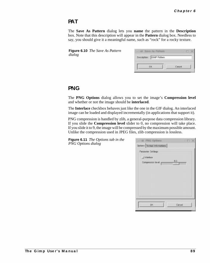
C h a p t e r 6
e.
edt it).
rary..unt.
PAT
The Save As Patterndialog lets youname the pattern in theDescriptionbox. Note that this description will appear in thePattern dialog box. Needless tosay, you should give it a meaningful name, such as “rock” for a rocky textur
PNG
The PNG Options dialog allows you to set the image’sCompression leveland whether or not the image should beinterlaced.
TheInterlace checkbox behaves just like the one in the GIF dialog. An interlacimage can be loaded and displayed incrementally (in applications that suppor
PNG compression is handled by zlib, a general-purpose data compression libIf you slide theCompression levelslider to 0, no compression will take placeIf you slide it to 9, the image will be compressed by the maximum possible amoUnlike the compression used in JPEG files, zlib compression is lossless.
Figure 6.10 The Save As Patterndialog
Figure 6.11 The Options tab in thePNG Options dialog
T h e G i m p U s e r ’ s M a n u a l 8 9

F i l e s A n d P r e f e r e n c e s
asomved.
ileshan
omareram.
Textual Informations lets you include information about the image, suchDescription, Author, etc. This is a good thing if you want to prevent anyone frstealing your image, but you should be aware that the information can be remo
PNM
The Save As PNMdialog is fairly self-explanatory.Raw means that the file issaved in binary format, whereasAscii will cause the file to be saved as asequence of printable characters. You’ll probably always want to save PNM fin Raw format, as it’s smaller (eight times smaller, in fact) and saves faster tAscii format.
PNM is a UNIX image format. It is often used to translate images to and frother formats. PNM is also used as an image format within programs, so if youa programmer you have to choose whether to use Raw or Ascii in your prog
Figure 6.12 The TextualInformations tab
Figure 6.13 The Save As PNM dialog
9 0 T h e G i m p U s e r ’ s M a n u a l

C h a p t e r 6
beage
es.
e, so
youtingrginage
in
on
dforted
POSTSCRIPT AND EPS
Saving your image asPostScript is significantly different from saving it asTIFF, GIF, JPEG, etc.
When you save an image as PostScript, you must specify theImage Size. Thinkof it as if you were specifying the size of the paper on which the image willprinted. Choose a reasonable image size. In other words, a 300x400 pixel imwon’t look very good if you stretch it out to the default size of 11.30x7.87 inchYou will almost always have to alter the paper size. To do so, change theWidthandHeight fields.
TheX-offset andY-offset fields can be thought of as themarginof your imag-inary paper. Checking thekeep aspect ratiocheckbox means that the imagesize will be automatically adjusted to be the same relative shape as your imagthat the image won’t be stretched out.
For example, let’s say you are going to save a 300x400 pixel image, and thatdecide that the resolution is going to be 100 pixels per inch (suitable for printo a 300 dpi laser printer). The image area would be 3x4 inches. If we add a maof 0.2 inches on top and bottom, and 0.2 inches on each side, then the total imsize will be 3.4x4.4 inches. So, let’s setWidth to 3, Height to 4, X-offset andY-offset to 0.20, Unit to Inch and Rotation to 0. This will result in yourimage being saved inportrait mode.
If you want to rotate your image by 90 degrees, you’ll have to switch valuesWidth and Height, and the image will be saved inlandscapemode. If you rotateyour image by 180 degrees, you’ll get an upside-downportrait mode, and if yourotate by 270 degrees you’ll get an upside-downlandscapemode. You can readmore about resolution and printing in “Pre-press And Color In Gimp” startingpage 197.
Clicking the Encapsulated PostScriptcheckbox will create an EncapsulatePostScript (.eps) file instead of a plain PostScript (.ps) file. EPS is usefulimporting an image into a page layout or an illustration program. Encapsula
Figure 6.14 The SavePostScript dialog
T h e G i m p U s e r ’ s M a n u a l 9 1

F i l e s A n d P r e f e r e n c e s
fes-
ckksion)
alog
, butct
Likeace.
Postscript is also a commonly requested file format when you print at a prosional printing company.
If you’re going to import your EPS file into another program, it is wise to chethePreviewbox. If you don’t, the program may not show what your image loolike on screen (it will either be displayed as a gray square or at very low resolutand the image will only appear when you print it out.
SUNRAS
This is the SunRas save dialog When you save a SunRas file, you’ll get a dibox asking if you wantRLE compression orStandard format (no compression).RLE compression is lossless so it’s generally a good idea to select this optionnote that RLE format supports only 4 or 8 bits per pixel. This will have no effeon the image, except that you can’t save Indexed images in SunRas.
TGA
When you save a Targa image, theSave As TGAdialog box asks if you wantRLE compression or no compression (RLE compression is not checked).SunRas compression, RLE is generally a good idea, since it will save disk sp
Figure 6.15 The SunRas Save
Figure 6.16 The Save As TGA dialog
9 2 T h e G i m p U s e r ’ s M a n u a l

C h a p t e r 6
phae
ans-luerted
TIFF
The Save As TIFF dialog asks what kind of compres-sion you want. Since TIFF compression islossless, youmight as well use it. UseLZW with 4, 8 and 24 bit imagesand Pack Bits with 1 bit (bitmap) images like FaxG3images, because Pack Bits is only designed to work on 1bit images (B&W).
TheFill Order determines how the bits in your image arefilled. The first option is Least Significant Bit (LSB) toMost Significant Bit (MSB), the default order on little-endian machines (for example, machines with Intel X86processors). It is also known asPC filling.
The other option selects a reverse fill order:MSB to LSB.This is the default order on big-endian machines (oneswith Motorola and SPARC processors, for instance). Thisis also known asMac filling .
If you want to import the image into FrameMaker or a sim-ilar program, setCompression to None and setFillOrder depending on the type of machine that the programruns on. Most programs are fairly flexible when it comes toimporting files, but this way you are safe.
XPM
The Save As XPM dialog appears when you save an image that has al(transparency).Alpha Threshold determines which alpha values should bconsidered transparent and which should be considered opaque.
For example, a threshold of 0.5 means that all alpha values under 128 will be trparent and all over 128 will be opaque (128 is half of the maximum channel va255). According to the source code, 16 bit and 24 bit XPM images are suppoon 16 bit displays; code for 8 bit images exists, but has not been tested.
Figure 6.17 The Save As TIFFdialog
Figure 6.18 TheSave As XPM dialog
T h e G i m p U s e r ’ s M a n u a l 9 3

F i l e s A n d P r e f e r e n c e s
RZ,aton
relso
ver,use
fd;
k-
nTheile.any
OTHER IMAGE FORMATS
The other image formats that Gimp supports, such as BMP, CEL, FITS, FLI, HHTL, Header, PCX, PIX, SGI, XCF, XWD, bzip2, gzip, etc., have no optionsthe time of this writing. Therefore, we can’t supply any special informationhow to save in those formats.
MAILING IMAGES
Gimp can mail images. This is a handy feature, particularly if you work in mothan one location. Then, you can mail your image home or to work. You can ause it to send digital Christmas cards to your friends and family. Note, howethat mail administrators may not be very happy if you mail large images, sothis feature with care.
Right-click|File| Mail Image to pop up theSend to Mail dialogbox. TheTo field is the email address of your friend.Subject is the subject ofyour email.Comment is a comment for the image, like “Here’s a nice picture omy new pet gnu.”Filename is the file name of the image that you want to senit should have the formatfilename.well-known_extension .
You also have to choose the mail message’sEncapsulation or coding type;you can choose eitherUuencodeor 64 bit MIME . It’s usually better to useMIME because it’s supported by most mail programs.
DISPLAYING IMAGES IN THE ROOT WINDOW
Right-click|File| Onroot lets you display an image as a repeated bacground pattern in the root window.
The root window is the “background” of your X Window System desktop. Ostart-up, most X desktops set the background to a specific color or image.background is normally set using a GUI application, or by changing a line in a fThe next time you start the desktop, the new background will be displayed (mdesktops allow you to do this without having to restart your desktop).
Figure 6.19 The Send to Maildialog
9 4 T h e G i m p U s e r ’ s M a n u a l

C h a p t e r 6
re-andck-
illnguse
dis-alsoof
is
nd
al
ts
nw
This setup will suit most ordinary users who only want to choose from a set of pconfigured backgrounds. But since Gimp is an image manipulation programyou are an image manipulator, you will probably want to create your own baground, and here’s where theOnroot feature comes in handy. With Onroot, youcan easily put the image you’re working with in the root window to see how it wlook. If you’re not happy with the result, you can keep manipulating it, displayiit in the root window again and again until you are satisfied. Then, you canyour window manager to display the finished image.
Onroot also has a dialog box where you can specify how the image will beplayed on the root window. There are five different options/settings. There isa preview screen, so you can easily see what it will look like. A quick overviewthe options is as follows:
• Tiled: This option will place your image (in its original size) in theupper-left corner, and place copies from left to right until the entire rowfilled. Then, it will put a copy of the image under the first and fill thesecond row. This will go on until the whole screen is filled. Since theimage hasn’t been scaled, it will probably be cropped at the right side ain the bottom of the screen.
• Full size: This option will stretch your image so it will cover the entirescreen. Unless the image is very large, it will (probably) lose its originratio and become blurry, since it will be stretched to fit the screen.
• Max aspect: This option will stretch your image with its ratio intact.This will most likely result in a cropped duplicate of your image unless iaspect ratio exactly matches that of your screen.
• Integer tiled: This option is nearly the same asTiled. The difference isthat there will be no cropped images as they will be stretched to fill thewindow.
• Free Hand: With this option you can place your image at any position othe root window. Initially, the image is placed in the center of the previescreen. You can then drag it to the location of your choice.
Figure 6.20 TheTo Root dialog
T h e G i m p U s e r ’ s M a n u a l 9 5

F i l e s A n d P r e f e r e n c e s
ou’reions
ond
ge
i,
to
rint-s theas
om
Not every desktop environment can handle each of these options, so when ycreating the right background image, take into account the background optyour desktop has to offer.
PRINTING IMAGES
Before you start to print from Gimp, you should know that only theactive layerof a layered image will be printed, so you must firstflatten (right-click|Layers| Flatten Image ) your image before printing. We’re not going todiscuss UNIX printing subsystems, spooling methods and the like, as it’s beythe scope of this book.
What kind of printer does Gimp support internally? To find out, open an imaand selectright-click|File| Print to pop up thePrint dialog box. Ifyou click on theSetup button and then on theDriver pull-down menu, you’llfind that Gimp supports the following printers:
• PostScript printers (including PostScript level 2)
• HP DeskJet 500, 500C, 520, 540C, 600C, 660C, 68xC, 69xC, 850C,855C, 855Cse, 855Cxi, 870Cse, 870Cxi, 1200C and 1600C printers
• HP LaserJet II, III, IIIp, IIIsi, 4, 4L, 4P, 4V, 4Si, 5, 5FS, 5L, 5P, 5SE, 5S6L and 6P printers
• EPSON Stylus Color, Color Pro, Color Pro XL, Color 400, Color 500,Color 600, Color 800, Color 1500, Color 1520 and Color 3000 printers
OTHER PRINT SETTINGS
Gimp supports most common printers internally, so you probably won’t needuseGhostScript.
GhostScript is a program that is often used to convert PostScript to another ping language, such as PCL, which is used by HP printers. Since PostScript imost common printing output for UNIX programs, GhostScript is often set upa filter that interacts with the printer system to convert the output on the fly frPostScript to PCL, which is fed to the HP printer.
9 6 T h e G i m p U s e r ’ s M a n u a l

C h a p t e r 6
ur
rawol-
on
box.
h a
However, if you have GhostScript installed and use it as a printer filter for yoprinters, then you’ll probably want to print using thePostScript Printeroption. We recommended that those of you with Ghostscript installed create aprinter device and let Gimp print directly to it, at least temporarily, so you can flow the examples in this manual more closely.
SETUP
Before you can print, you must enter theSetup dialog. Setup tells Gimp whattype of printer you are using. As you might imagine, this is crucial informatiwhen it comes to printing.
First, specify thePrinter (actually the printer’s queue) you’d like to print to in thedrop-down menu, then click on the Setup button to access the Setup dialog
In the SetupDriver pull-down menu, you specify what type of printer you’reusing. If you have a PS or PS level 2 printer, you can provide your printer witPPD File.
Figure 6.21 The Printer
Figure 6.22 The printer Setupdialog
T h e G i m p U s e r ’ s M a n u a l 9 7

F i l e s A n d P r e f e r e n c e s
aa-
in-
yoube
can
t;-
d by
nifset,up
whatur-
t
g
se
.
Tip: A PPD file is a file that describes your printer’s capabilities. By providingPPD file specific to your printer, you’ll be able to use your printer’s special fetures (like resolution, media source and media type).
Just browse and choose the PPD file that comes with the printer driver for Wdows, or you can download it from Adobe’s FTP site.
Gimp doesn’t come with PPD files, so you have to get them yourself. Usually,get it from the Windows driver for your PostScript printer, but sometimes it canhard to extract the PPD file from the Windows driver. If that is the case, youget the PPD file fromftp.adobe.com/pub/adobe/printerdrivers/win/all/ppdfiles . The files at Adobe’s FTP site have the following formabrand_name_of_printer.exe , so you either need Windows or an emulator to unpack the driver (execute the file).
If you don’t have a PostScript printer, just choose one of the printers supporteGimp from the drop-down menu.
In theCommand input field you’ll see the print command that will be used wheyou print. Normally this is determined when you compile the print plug-in. Butthe command is wrong, you can correct it here. Once everything is correctlypress OK. If you don’t have a command field, don’t worry; Gimp has been setso well that there is no need for it.
THE PRINT DIALOG
The main dialog box may now have changed its appearance depending onfeatures your printer supports. We will describe all of the options, but don’t be sprised if your printer only supports a few of them.
• Media Size: Thesize of paper you use in your printer. Gimp supportsLetter, Legal, Tabloid, A4, A3 and other paper sizes.
• Media Type: Refers to thetype of paper you use, such asTransparent,Glossy, etc.
• Media Source: The way to specify the tray containing the paper onwhich you’d like to print. As you might imagine, this is heavily dependenon your printer’s capabilities.
• Orientation menu: Lets you select whether you want to print inLandscape or Portrait mode. You can also let Gimp decide by selectinAuto.
• Resolution: Provided because different printers support differentresolutions. In this field, you can specify what resolution you want to ufor your print job. This option can come in handy; for example, youprobably don’t want to use high resolution when printing a draft. We’lldiscuss resolution in more detail a bit later when we talk about scaling
• Output type: If you have a color printer, useColor mode; otherwise,useB&W (you can also useB&W on a color printer, of course).
9 8 T h e G i m p U s e r ’ s M a n u a l

C h a p t e r 6
ht.eur
age
itr
PI
tionter.nge
inter
d tor Inore
, so
ssht.
,erveAndgpro-
lym-ndthe
• Brightness is set by default to 100, which is fine for printing to lasersand black-and-white inkjets. Usually, though, you will have to increasethis value when printing to a color inkjet. The author of Gimp’s printerinterface recommends a setting of 125 to 150, but for us, that’s too brigWe use 110 for our Deskjet 870Cxi. The bottom line is that you will havto experiment a bit to find out what setting gives the best results on yoprinter.
• Scaling: When you open the Print dialog box, Scaling is set to thedefault value 100, and the image will be stretched to cover the entire p(with a margin of 6 mm on each side, and 13 mm on top and bottom).Ifyou use this scaling factor on a small image, it will get so enlarged thatwill look jagged and ugly, because the effective resolution (in pixels peinch) will be extremely low.
The nice thing about Gimp’s printer interface is that you can set the scale inPPI.As we have already mentioned, PPI stands forpixels per inch and representsthe resolutionof the printed image.We recommend that you always use the Poption; otherwise, you will have little control over print quality.
So, what PPI value should you use? Well, it depends on your printer. A suggesis to use 72 ppi for a 300 dpi laser printer and 110 ppi for a 600 dpi laser prinNote: If you can set the resolution in the printer dialog, remember to also chathe PPI value.
But our suggestion is not absolute. For example, if you have a PostScript prthat uses AM screening, the PPI should be around 1.6 to 2 times theLPI (linesper inch) of the printer.
As you may have noticed, the more we discuss this topic, the more you’ll neeunderstand. We strongly recommend that you read “Pre-press And ColoGimp” on page 197, where we discuss the complex subject of printing in mdetail.
However, we can give you a few simple guidelines. A 300 dpilaserprinter willneed at least 60 ppi, and a 600 dpilaserprinter will need 100 ppi (minimum). Ageneral rule is that inkjet printers get away with a lower ppi than laser printerstry 50 ppi for a 300 dpiinkjet printer and 90 ppi for a 600 dpiinkjet printer.
If you find this printing jargon confusing, stick to our guidelines or read “Pre-preAnd Color In Gimp” starting on page 197. If you have an inkjet printer it migalso be a good idea to read “Scanning, The Web And Printing” on page 259
If you’d like to use thePercentoption, remember that small images (set at 100%which means 100% of the paper size) will print at a very low resolution. In ordto get a nice printout, the image will have to be relatively large and you will hato scale it down to increase the resolution. Read more about this in “Pre-pressColor In Gimp” on page 197. A 300x400 pixel image will look fine with a scalinof around 30% (assuming that you use A4 paper and a 300 dpi printer). Thecedure is the same as when we saved in PostScript format.
Tip: If you are making a draft of a large image, like a poster, you will probabstart by working with a small image in order to avoid heavily loading your coputer. If you just want a quick printout of the draft, use the Percent function aenlarge the image. Since it is a draft, you only want a quick look anyway, soquality is not that important.
T h e G i m p U s e r ’ s M a n u a l 9 9
F i l e s A n d P r e f e r e n c e s
ved
lter-
esst
calurde.anourad
veur-
tartf tak-
nd
andl.
an
ues
d ofage
There’s also aprint to file choice in thePrinter pull-down menu. When youselect File, the data that would normally go to your printer will instead be sato a file. When you press thePrint button, a file dialog will appear where you canspecify the output file name (and path). Printing to a file is quite handy as an anative to saving the file asPostScript. In our opinion, it’s often easier to printto file (in PS mode) than to save as PS, mainly because you don’t have to mwith theSave Assettings. However, even if you print to file, it’s still importanthat you set the resolution correctly.
Printing to a file is also an option when you want to print your image at the loprinter. You only have to get a copy of its printer’s PPD file and install it on yosystem. When the Print dialog appears, enter the setup in “print to file” moChoose the PPD file provided by your print house and click on OK. Now you cset the options that its imaging hardware supports. Once you’ve “printed” yimage to a file, simply deliver the PS file to the local print house for printing. Remore about this in “Pre-press And Color In Gimp” on page 197.
GIMP PREFERENCES
In the Preferences dialog box (right-click|File| Preferences ),you’ll find a lot of Gimp-related settings. There are four tabs:Display, Inter-face, Environment andDirectories.
To save any changes permanently, click on theSavebutton; if you pressCancel,all your changes will be discarded. If you pressOK , your changes will affectGimp at once, though not all values will be affected (dir values like swap will hano effect). If you press OK and not Save, your changes will only affect the crently running Gimp and will not be saved for future Gimp sessions.
Note: To enable your Saved modifications you must first quit Gimp and then sit up again. We recommend that you use Save and then restart Gimp instead oing a chance with OK.
DISPLAY
On theDisplay tab, you can set the default size for new images (in pixels), athe default image type (RGB or grayscale). You can also set thePreview size.If your computer has a small screen and is low on system resources (like RAMprocessor speed) you’ll generally want to keep the Preview size set to smal
Check Sizelets you choose the size of the checks in the checkerboard onimage composition screen that is used to represent transparency, andTranspar-ency Type lets you specify the grayscale tone of the checks. The default valshould be fine for just about any work.
INTERPOLATION
When you scale an image to make it bigger, Gimp has to calculate what kinpixels it needs to insert between the original pixels (in order to make the imbigger). This is calledinterpolation. Linear interpolation is faster and also
1 0 0 T h e G i m p U s e r ’ s M a n u a l

C h a p t e r 6
n the
ys-bicult.
our
heard-can
syou
oveem
t be
leaner on system resources, but it does not produce as high a level of detail ioutput image ascubic interpolation does. To get a nice-looking image with alot of detail when you scale it, check the Cubic interpolation checkbox. If your stem is not up to running with cubic interpolation enabled, make sure the Cuinterpolation checkbox is not checked. Gimp uses linear interpolation by defa
INTERFACE
On theInterface tab, you can setLevels of undo. Setting it to a high number(over 10) requires a lot of disk space, so use with care if disk space is low on ysystem.
Resize window on zoommeans that the canvas size will always adapt to tamount of zoom you use, so you’ll always be able to see the entire image regless of zoom level. Our advice is to keep this option unchecked because youeasily enable and disable it in theZoom Options dialog box. Read more aboutthis in “Zoom” on page 150.
Show tool tips is a nice feature; Gimp will automatically pop up small tipabout the tool when you move the mouse over the tool. We recommend thatenable tool tips until you have learned every tool(i.e., never).
By default Gimp changes the cursor symbol. For example, if you use the Mtool, your cursor will be the move symbol. However, this consumes systresources, so if you are extremely low on resources, check theDisable cursorupdating checkbox. Bear in mind that this can be unwise because you won’able to see what mode you are in.
Figure 6.23 The Displaytab
T h e G i m p U s e r ’ s M a n u a l 1 0 1

F i l e s A n d P r e f e r e n c e s
pear
lue
inrnedis
urerom
nly
, sohis
atile
itting0
then
You can also set the speed of the “marching ants” (the blinking dots that apwhenever you make a selection). The value in themarching ants speedinputfield is the amount of time between updates (in milliseconds), so a lower vamakes the ants march faster.
ENVIRONMENT
On the Environment tab, you’ll see theConservative memory usagecheckbox. Gimp will usually trade memory consumption for improvementsspeed. Checking Conservative memory usage will make Gimp more conceabout memory, but it will also slow things down, so only use it when memoryscarce.
Tile cache sizeis the amount of memory that Gimp consumes in order to ensthat it doesn’t damage the tile memory when Gimp moves memory to and fdisk. Gimp uses its own swap file on disk to handle memory; this is thetile mem-ory. Since Gimp has its own swap file, you can edit really large images. The orestraining factor is disk space.
We all know that keeping program memory on disk makes the program slowwe don’t want the memory that Gimp uses to edit an image to be on our disk. Tis where thetile cachecomes in. You can specify the amount of tile memory thyou want to put in our computer’s main memory. The rest will stay in Gimp’s tmemory swap file. Setting this value high will make Gimp faster, becausedoesn’t need to keep all that information in the swap file. We recommend setit to 32 MB on a computer with 128 MB RAM, 16 MB on a 64 MB system and 1MB on a smaller system (note that Gimp will continue to work even if you setTile cache size to 0).Note that a big tile cache will only affect Gimp’s speed o
Figure 6.24 The Interface tab
1 0 2 T h e G i m p U s e r ’ s M a n u a l

C h a p t e r 6
layan-usebe
kou
-
large images.Using a 64 MB tile cache when you work on a 2 MBimage will notmake Gimp faster.
If you’re working on an 8 bit display, you’ll definitely want to use theInstallcolormap option. Because most of the 256 available colors on your 8 bit dispwill have already been claimed by other applications (such as the window mager, Netscape, etc.) Gimp, and the images it displays, will only be allowed tothe leftover colors. As you probably realize, under such conditions Gimp willquite useless.
Colormap cycling affects the “marching ants” selection border. If you checthis option, the “ants” will be replaced with a smooth line. This line is dark as ydrag the selection, and turns bright when you release the mouse button.
DIRECTORIES
The most important directories that you can manipulate in theDirectories folderare Temp and Swap. TheTemp directory is where Gimp stores all of its temporary data, like working palettes and images. TheSwapdirectory is where Gimpkeeps its swap file for the tile-based memory system.
Figure 6.25 The Environmenttab
T h e G i m p U s e r ’ s M a n u a l 1 0 3

F i l e s A n d P r e f e r e n c e s
are
to
swapeow
p,mpourc-
ay beem-ve
SuggestionsHow should you configure these directories for optimal performance? If youon a system that mounts home directories from aserver over NFS and/or youhave only a fixedquota of disk space that you can use, you will probably wantplace your Swap directories on a local temporary directory such as/tmp . Other-wise, you won’t have any disk space left to save your images, because thefile can (almost always) getverybig. Another reason to do this is that if you havto send image data to and from a swap file over the Net, Gimp will be terribly slbecause it has to wait for network traffic to finish before it can proceed.
Temp is a bit different. Most of the files here will disappear when you exit Gimbut some will remain (such as working palettes) so you will probably want a Tedirectory that you don’t share with other people, and that isn’t cleared if yreboot your workstation. A good idea is to make a personal directory unde/usr/tmp or /var/tmp . For example, in a terminal window create a temp diretory with the command:
mkdir /usr/tmp/<your_user_name >
Set this directory to be yourTemp directory.
The other directories for brushes, gradients, palettes, patterns and plug-ins mleft as they are, or modified to suit your special needs. If you change them, rember to move your Gimp add-ons to the right place. If you don’t, you may not haany plug-ins available the next time you start Gimp.
Figure 6.26 The Directorytab
1 0 4 T h e G i m p U s e r ’ s M a n u a l

C h a p t e r 6
s-
our
ngals.
pe-
is
nself,t’so useingver
MISCELLANEOUS FEATURES AND EXTENSIONS
TIP OF THE DAY
In the toolbox, click onFile|Tip of the day . TheTip of the day is a handyfeature for new Gimp users. You can browse the tips by clickingPrev. Tip andNext Tip. To turn off Tip of the day, uncheck theShow tip next time checkboxon the Tip of the day dialog box. The file containing all the tips is in the Gimp sytem-wide data directory and is calledgimp_tips.txt , so if you are a systemadministrator, you can edit this file and add new tips for the Gimp users on ysystem.
DB BROWSER
In the DB browser you can search for GimpPDB callsandroutines. This featureis mainly for people that deal with scripts and plug-ins. Even if you are not writiscripts or plug-ins, this can be a good source of information on Gimp’s internYou can search the database for both PDBprocedure namesand informationabout the procedure. If you call theDB Browser from the Script-Fu Console, youcan also apply the PDB command to the console.
PDB HELP
This is another interface to the Gimp PDB. With this extension you can run a scific PDB call on your image. To do this, simply click onRun, which will bringup a dialog asking for information. As with the DB Browser, this extensionmainly for developers.
GIMPTCL CONSOLIO
Gimp’s main scripting language isScheme, which is one of the many scriptinglanguages available forUNIX . Consolio is written inTcl, and you can use it whenyou create Tcl scripting for Gimp.
SCRIPTING
If you are familiar with Tcl or Perl, you probably don’t want to bother to learScheme. If you are a user without technical background, you may well ask your“Whyshould Ibother learningsomeobscureUNIXscripting language?”Well, lefirst state that there is no absolute requirement to learn a scripting language tGimp. You can happily use Gimp without giving a thought to learning any scriptlanguage. But if you find yourself performing a certain operation over and oagain, wouldn’t it be nice to automate it?
T h e G i m p U s e r ’ s M a n u a l 1 0 5
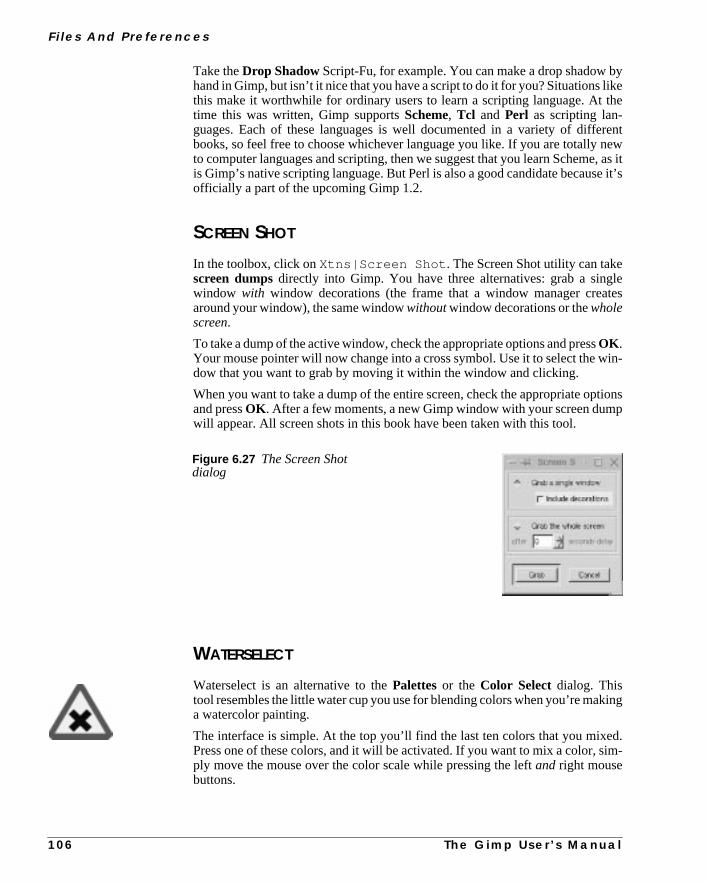
F i l e s A n d P r e f e r e n c e s
byikethe
rentew, as ite it’s
letes
in-
tionsp
ing
d.im-
Take theDrop ShadowScript-Fu, for example. You can make a drop shadowhand in Gimp, but isn’t it nice that you have a script to do it for you? Situations lthis make it worthwhile for ordinary users to learn a scripting language. Attime this was written, Gimp supportsScheme, Tcl and Perl as scripting lan-guages. Each of these languages is well documented in a variety of diffebooks, so feel free to choose whichever language you like. If you are totally nto computer languages and scripting, then we suggest that you learn Schemeis Gimp’s native scripting language. But Perl is also a good candidate becausofficially a part of the upcoming Gimp 1.2.
SCREEN SHOT
In the toolbox, click onXtns|Screen Shot . The Screen Shot utility can takescreen dumpsdirectly into Gimp. You have three alternatives: grab a singwindow with window decorations (the frame that a window manager creaaround your window), the same windowwithoutwindow decorations or thewholescreen.
To take a dump of the active window, check the appropriate options and pressOK .Your mouse pointer will now change into a cross symbol. Use it to select the wdow that you want to grab by moving it within the window and clicking.
When you want to take a dump of the entire screen, check the appropriate opand pressOK . After a few moments, a new Gimp window with your screen dumwill appear. All screen shots in this book have been taken with this tool.
WATERSELECT
Waterselect is an alternative to thePalettesor the Color Select dialog. Thistool resembles the little water cup you use for blending colors when you’re maka watercolor painting.
The interface is simple. At the top you’ll find the last ten colors that you mixePress one of these colors, and it will be activated. If you want to mix a color, sply move the mouse over the color scale while pressing the leftand right mousebuttons.
Figure 6.27 The Screen Shotdialog
1 0 6 T h e G i m p U s e r ’ s M a n u a l

C h a p t e r 6
thatgethenthe
en of
oser youust
theally
The left mouse button, which mixes todarker colors, overrides the right mousebutton. If the color gets too dark, temporarily release the left mouse button soyou only press the right mouse button while moving the mouse. The color willlighter, just as if you had added more water. Release both mouse buttons wyou’re satisfied, and the chosen color will appear in the active color swatch intoolbox. Press OK or Cancel to close the Waterselect window.
WEB BROWSER
TheWeb Browser (Xtns|Web Browser ) allows you to open a web site fromwithin Gimp. You’ll find a few shortcuts to important locations like Gimp.org, thPlug-in Registry, Gimp news and so on. You can also open the online versiotheGimp User’s Manual this way.
To open a site that is not available in the shortcut menu, selectOpen URL. Thisoption pops up a dialog box asking you about the site. You can also chowhether you want to open the site in an existing Netscape session, or whethewant to open a new Netscape window. Naturally, for this to work, Netscape mbe installed and in your path.
If you want to change or add a shortcut, you have to edit the script that controlsbehavior of this extension. The script is called web-browser.scm and is usulocated in/usr/local/share/gimp/scripts/ , but this is naturally site-dependent. Just copy it to your personal gimp script directory (cp/usr/local/share/gimp/scripts/web-browser.scm/your/home/.gimp/scripts) and edit it in a text editor.
Figure 6.28 The Waterselectdialog
T h e G i m p U s e r ’ s M a n u a l 1 0 7


C H A P T E R
7 Selection ToolsIn this chapter, you’ll learn about making selections,and how to use the different selection tools. We’llalso explain why strange things happen when youtry to move your selection for the first time.

S e l e c t i o n To o l s
tore-antor-
sedlect
ben
illkingssoke
ou’ll
BASIC CONTROLS
The first six tools in the toolbox areselection tools. In orderto manipulate a specific part of your image, you first needselectthat area. The trick is to find the right selection tool (othe right combination of tools) to make your selection corrspond as exactly as possible to the part of the image you w
to work with. Even the untrained eye can pick out a sloppy selection, so it’s imptant that your work looks convincing. The selection tools in the toolbox are ufor quick, simple selections. For really advanced selection work, read “SeMenu” on page 307 and “Channels And Duotones” starting on page 351.
TOGGLE
When you have made a selection, theboundary of the selection becomes a blink-ing dotted line, often referred to as “marching ants.” Your selection is now theonly active part of your image; the rest of the image is masked and will notaffected. If you find the blinking line distracting, Gimp allows you to switch it oand off with right-click|Select| Toggle menu. Note that the yellow-dottedlayer boundaries are also affected by the Toggle command.
SELECTION CONTROL
If you’re not happy with your selection, just make a new one; the first winstantly disappear and be replaced by your new selection. If you regret maselections at all, just click once in your image (with the rectangular, ellipse or latool active) and the selection will be gone. However, you might want to mamore than one selection, or combine several selections into one — for that yhave to use the Shift and Ctrl keys.
Pressing the Shift key as you create a selection allows you toadda selection. If theselections touch, they will be combined into one single selection (a union).
Figure 7.1 Selection union
1 1 0 T h e G i m p U s e r ’ s M a n u a l

C h a p t e r 7
ver-ethe
Pressing the Ctrl key will do the opposite; dragging a second selection that olaps the first willsubtract that area from the first selection (leaving you with thdifference). Just pressing Ctrl while drawing selections won’t do anything —selections have to touch each other.
If you press both the Ctrl and Shift keys simultaneously, you’ll get theintersec-tion of the two, i.e., only the portion that is part of both selections.
While makingadditions or subtractions, remember “to err is human.” It’s agood idea to keep your middle finger prepared to press theright mouse but-ton. If you do this and thenreleasethe left mouse button, the selection youare drawing will disappear.
Figure 7.2 Selectionsubtraction
Figure 7.3 Selection
T h e G i m p U s e r ’ s M a n u a l 1 1 1
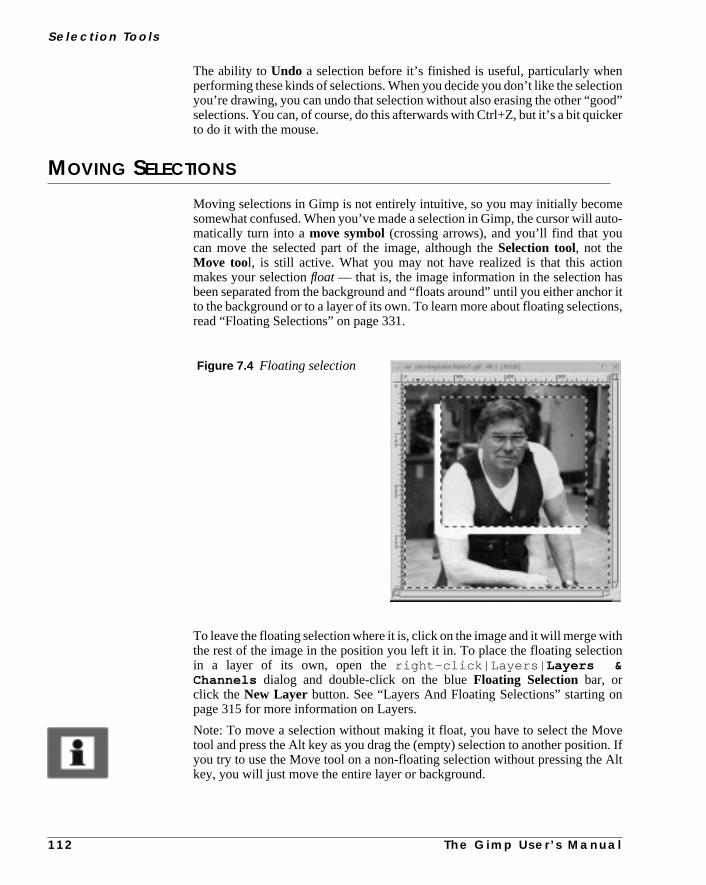
S e l e c t i o n To o l s
ntionod”ker
euto-
nsor itns,
ithion
n
ven. IfAlt
The ability toUndo a selection before it’s finished is useful, particularly wheperforming these kinds of selections. When you decide you don’t like the selecyou’re drawing, you can undo that selection without also erasing the other “goselections. You can, of course, do this afterwards with Ctrl+Z, but it’s a bit quicto do it with the mouse.
MOVING SELECTIONS
Moving selections in Gimp is not entirely intuitive, so you may initially becomsomewhat confused. When you’ve made a selection in Gimp, the cursor will amatically turn into amove symbol(crossing arrows), and you’ll find that youcan move the selected part of the image, although theSelection tool, not theMove tool, is still active. What you may not have realized is that this actiomakes your selectionfloat — that is, the image information in the selection habeen separated from the background and “floats around” until you either anchto the background or to a layer of its own. To learn more about floating selectioread “Floating Selections” on page 331.
To leave the floating selection where it is, click on the image and it will merge wthe rest of the image in the position you left it in. To place the floating selectin a layer of its own, open theright-click|Layers| Layers &Channels dialog and double-click on the blueFloating Selection bar, orclick the New Layer button. See “Layers And Floating Selections” starting opage 315 for more information on Layers.
Note: To move a selection without making it float, you have to select the Motool and press the Alt key as you drag the (empty) selection to another positioyou try to use the Move tool on a non-floating selection without pressing thekey, you will just move the entire layer or background.
Figure 7.4 Floating selection
1 1 2 T h e G i m p U s e r ’ s M a n u a l

C h a p t e r 7
ondllas
ost
mis-’ll
ageher
w it
, sof thetheers
lace
SELECTIONS WITHIN FLOATING SELECTIONS
If you have already moved the floating selection once, you can’t do it a sectime without switching to the Move tool. If the Selection tool is still active, you’just form a new selection inside the float. However, this isn’t really a selectionyou know it — the dotted outline is gray instead of black, it doesn’t blink and mimportantly, the rest of the floating selection seems to have disappeared!
The appearance of such a selection can be quite annoying if you created it bytake (which is not uncommon). Don’t panic — just press Ctrl+Z (Undo) and yoube back to where you started.
Note that this doesn’t happen when you move floats that aretext selectionsorpasted objects, because then no Select tool is active.
The Old Way Of Manipulating Floating SelectionsThis effect is a remnant from the time beforeLayers, when floating selectionsand channel operations were the only tools for working with composite iminformation. Making selections within the float was used as a quick, but ratineffective,mask effect. Now that Gimp supportsLayers, which is much moresophisticated, there is really no need for this kind of operation anymore.
However, because this behavior has confused many users, we’ll explain howorks:
What happens is that the contents in the floating selection become invisiblethat you can see the background through it. It’s only inside the boundaries ogray-lined subselection(s) that you’ll be able to see the original contents offloat. This part of the float is now the only area that can be affected by paint, filtor other operations. The rest of the float ismasked, and will not be changed. Youcan make a new subselection at any time, in which case this selection will rep
Figure 7.5 Selections withinfloating selections
T h e G i m p U s e r ’ s M a n u a l 1 1 3

S e l e c t i o n To o l s
lec-
agap toThem-nd
lefte
e orh toith-ou
ticalor-
the old one, and the new selection area will show another part of the floating setion.
This gray subselectionwon’t turn into a normal selection until yousaveordelete the floating selection. To sum up, you have three options for floats:
• As we mentioned earlier, you cansave a float in a new layer by double-clicking on the thumbnail bar, or by pressing theNew Layer button intheright-click|Layers| Layers & Channels dialog.
• You candelete it with theDelete Layer button, in which case the entirecontent of the float will beerased.
• The third option is to click on theAnchor Layer button, which willmerge the floating selection with the background (the same effect asclicking in the image). Anchoring will cause everything in the floatingselection to be erased except the information inside the subselection.
In all of these scenarios, the subselection will become a normal selection.
GUIDES
To place your selections exactly where you want them, use thehorizontal andvertical guides. Guides are vertical or horizontal dotted lines that you can drinto the image canvas from the rulers. Because selections and layers will snguides, they are a great help when you want to align different image objects.guides will not show up in your output image. They are only visible on the coputer monitor and in Gimp’s native file format (XCF). To switch the guides on aoff, click theToggle Guides radio button in theright-click|View menu.
With a selection tool, drag the guide down from the top ruler or across from theruler. Use theMove tool to change the position of the guides (notice how thmove symbolchanges into apointing hand when it touches aguide). Snapto guides is set by default in theView menu. If this option is checked, movingany kind of selection close to the guides causes it to “stick” or snap to it.
You can also use the guides to specify exactly where you want your squarellipse selection to start. If you use the Ctrl key and start dragging close enougthe point where the guides cross, that will be the center of the new selection. Wout Ctrl, the selection will start from the cross and continue in the direction ydrag.
You can easily adapt the size, shape and position of a rectangular or ellipselection to the guides by drawing it within the frame of two vertical and two hizontal guides (just using the guides as visual references).
1 1 4 T h e G i m p U s e r ’ s M a n u a l
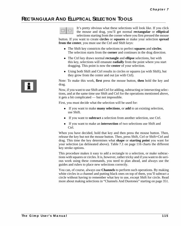
C h a p t e r 7
use
ut
ec-ove,
hen,and
erent
trac-eri-e the
ct aad
351.
RECTANGULAR AND ELLIPTICAL SELECTION TOOLS
It’s pretty obvious what these selections will look like. If you clickthe mouse and drag, you’ll get normalrectangular or ellipticalselections starting from the corner where you first pressed the mo
button. If you want to createcircles or squaresor make your selectionspreadfrom the center, you must use the Ctrl and Shift keys:
• The Shift key constricts the selections to perfectsquares andcircles.The selection starts from thecorner and continues in the drag direction.
• The Ctrl key draws normalrectangle andellipse selections, but withthis key, selections will emanateradially from the point where you startdragging. This point is now thecenter of your selection.
• Using both Shift and Ctrl results in circles or squares (as with Shift), bthey grow from the center and out (as with Ctrl).
Note: To make this work,first press the mouse button,then hold the key anddrag.
Now, if you want to use Shift and Ctrl for adding, subtracting or intersecting seltions, and at the same time use Shift and Ctrl for the operations mentioned abit gets a bit complicated — but not impossible.
First, you must decide what the selection will be used for:
• If you want to makemany selections, oradd to an existing selection,use Shift.
• If you want tosubtract a selection from another selection, use Ctrl.
• If you want to make anintersectionof two selections use Shift andCtrl.
When you have decided, hold that key and then press the mouse button. Trelease the key but not the mouse button. Then, press Shift, Ctrl or Shift+Ctrldrag. This time the key determines whatshapeor starting point you want foryour selection (as delineated above). Table 7.1 on page 116 charts the diffkey stroke options.
This procedure makes it easy to add a rectangle to a selection, or make subtions with squares or circles. It is, however, rather tricky and if you want to do sous work using these commands, you need to plan ahead, and always usguides and rulers to place new selections correctly.
You can, of course, always useChannelsto perform such operations. By makingwhite circles in a channel and putting black ones on top of them, you’ll subtracircle without having to remember what key to use, except Shift for circle. Remore about making selections in “Channels And Duotones” starting on page
T h e G i m p U s e r ’ s M a n u a l 1 1 5

S e l e c t i o n To o l s
g
avewillthe
SUMMARY
To create selections:
1. Press mouse
2. Press key and drag
To add, subtract or intersect with other selections:
1. Press key
2. Press mouse and drag
To create a selection of a certain shape or from a certain direction,and usethat selection to add/subtract/intersect:
1. Press key 1 to determine effect
2. Press mouse
3. Release key 1, but not mouse
4. Press new key 2 to determine shape or direction, and drag
SELECTION OPTIONS
If you double-click on a button in the toolbox, you’ll see a little window showinyou that tool’s options. For example, if you double-click on theSelect ellipti-cal regions button in the toolbox, you’ll see theTool Options dialog shownin Figure 7.6 . Once you have accessed the Tool Options dialog, you don’t hto repeat this procedure to view the tool options for another tool. The dialogstay on screen, but it will change when you select another tool, displayingoptions available for that tool.
Table 7.1 Selection control
Key2=ShiftCircle
Key2=CtrlCenter
Key2=BothCircle+Center No Key 2
Key1=ShiftAdding
Add circlefrom corner
Add ellipsefrom center
Add circlefrom center
Add ellipsefrom corner
Key1=CtrlSubtracting
Subtract circlefrom corner
Subtractellipse fromcenter
Subtract circlefrom center
Subtractellipse fromcorner
Key1=BothIntersect
Intersect circlefrom corner
Intersectellipse fromcenter
Intersect circlefrom center
Intersectellipse fromcorner
No Key 1 Create circlefrom corner
Create ellipsefrom center
Create circlefrom center
Create ellipsefrom corner
1 1 6 T h e G i m p U s e r ’ s M a n u a l

C h a p t e r 7
s theanti-
tlyet-
.
nt. Itloserndh-
ANTIALIASING
For most select tools, you have the option ofAntialiasing. Antialiasing is aneffect used on curves and boundaries of high contrast areas, which makecurve or boundary look softer and smoother. The most common use is thealiasing of letters in bitmapped images, because it takes away thejaggies (thevisible jagged and pixelly edges of the letter’s curves in low resolution). It sofblends the edge pixels with the background, which will make curves look a lot bter, but also a bit blurred. So you gain in smoothness, but lose in sharpness
FEATHER
For the Rectangular selecttool, the only option isFeather. Feather meansthat you can choose to make the peripheral parts of your selection transparewill be opaque in the middle, and get more and more transparent as you get cto the edges. This is very useful if you want to make something look soft ablurry, like soft shadows or glowing edges, or if you’d like to use collage tecniques with thePasteor Paste Into commands.
Figure 7.6 Selection option dialog
Figure 7.7 The differencebetween using and not usingantialiasing
T h e G i m p U s e r ’ s M a n u a l 1 1 7

S e l e c t i o n To o l s
t thea too in
elec-
yin
tool
se
sededhe
tru-
ortedcoulde wasingol.
An image you paste into a feathered selection will get soft and transparent aedges and blend in nicely with your background. It is also usually a good ideuse a small amount of feather (a Feather Radius of around 5-10 pixels will dmost cases) if you want to select something that is to becopied, moved or cutandpasted, because the feathered edges will compensate for an imperfect stion edge and make it blend into the background.
THE FREE-HAND SELECTION TOOL
The Free-hand selectiontool, or lasso, lets you create a selection bdrawing a free-hand form with it. You close a free selection by endingthe point you started from. If you draw an open shape, this selection
will close it for you.
Tip: Usually, you can’t select a complex area with just one selection tool. Umore than one and add the selections together.
The lasso is an excellent tool for fixing up selections. If you see that you’ve missome pixels, it is easy to correct this with Shift+ or Ctrl+ lasso. As we explainearlier in “Selection Control” on page 110, Shift+ a selection tool will add to tselection, and Ctrl+ a selection tool will subtract from a selection.
As I’m sure you have noticed, the mouse isn’t a very sophisticated drawing insment. The good news is that the Gimp now fully supportsdigitized tablets (likethe Wacom ArtPad), and pressure-sensitive pencils. X programs have suppsuch devices as a substitute for a mouse for a long time. This means that youuse a Wacom device as a pointer or pencil, but the pressure-sensitive featurnot available. Gimp now has patches to make this work. Believe me — workwith lassos, pencils and brushes is dramatically different with an accurate to
OPTIONS
The options for the Free-hand selection tool are the same as for theEllipse selec-tion tool: Antialiasing andFeather. Read about them in “Selection Options” onpage 116.
Figure 7.8 An example of feathering
1 1 8 T h e G i m p U s e r ’ s M a n u a l

C h a p t e r 7
s.illtoo
en-ssthe
ase
rtedesed
tion
andmore
it’sectck-
our
if-n is
s.
FUZZY SELECT
The Fuzzy Selecttool looks like the Photoshop magic wand and workmuch the same way.Fuzzy Selectselects adjacent pixels of similar colorIt starts selecting when you click at a spot in the image. The wand w
select the color on that spot, and continue outwards until it thinks the color getsdifferent.
FUZZY SELECT OPTIONS
The options dialog doesn’t provide a control button for controlling the wand’s ssitivity. To control the wand’s sensitivity, after you position the cursor and prethe mouse button, drag the cursor (without releasing the mouse button) fromupper-left corner, either to the right or straight down (it doesn’t matter) to increfrom a small, stingy selection to a very generous one.
Be careful where you start. If you select the wrong spot, you might get the inveselection of what you wanted.In other words, selecting the wrong spot may makthe wand select everything except your choice. (If you have a black, antialiaobject on a white background, you can end up with a white to gray selecinstead of a black to gray one if you are not careful.)
The wand is the perfect tool to select sharp-edged objects in an image. The wis easy and fun to use, so the beginner often starts out using the wand a lot. Aexperienced user will find that tools like theBezier tool, Color Selector AlphaChannelsare often more efficient for selection, and use the wand less. Still,very useful for selecting an area within a contour, or for touching up imperfselections. The wand is also very efficient for removing the remains of the baground color from a cut and pasted selection.
The Fuzzy Selection Optionsdialog includes a checkbox calledSampleMerged. This option becomes relevant only when you have several layers in yimage, and the active layer is either semi-transparent or is set to anotherLayerMode thanNormal. If this is the case, the colors present in the layer will be dferent from the colors in the composite image. If the Sample Merged optiounchecked, the wand will only react to the color in theactive layerwhen it createsa selection. If it is checked it will react to the composite color of all visible layer
Figure 7.9 The Fuzzy Selection option dialog
T h e G i m p U s e r ’ s M a n u a l 1 1 9

S e l e c t i o n To o l s
.
osts is
n
nt,
licktry
t clickover
THE BEZIER SELECTION TOOL
In our opinion, theBezier selection tool is one of the most useful toolsYou’ll find Bezier curves in all major drawing or imaging softwarepackages.
USE BEZIERS AS A SIMPLE DRAWING TOOL
The Bezier selection is the equivalent of “Pentool Paths” in Photoshop. Mdrawing in programs like Corel, Illustrator, Freehand or even 3-D programdone with Bezier curves. Because Gimp is based onbitmaps and not onvectorgraphics(like Corel or Illustrator), you can’t draw with Bezier curves, but you camake advanced selections.
As far as drawing with Bezier tools goes, I don’t count usingStroke (right-click|Edit| Stroke ) on a Bezier curve, or making aBorder from a bezierselection withright-click|Select| Border , and then filling the border,as drawing. If you just want to add a simple drawing, this can be quite sufficiebut if you want to create a more advanced drawing, use theGfig plug-in in theright-click|Filters| Render menu, or do it in a commercial drawingprogram, convert it to suitable format and import it to Gimp.
CONTROL POINTS
You use the Bezier select tool by clicking outsplines or anchor points in arough approximation of the shape you want. You click, move the cursor and cagain to make straight lines and click and drag to make curves. Don’t bother toto make curves at this stage though, unless you’re an experienced user. Jusout a rough, angular shape and make sure you close it by placing the last pointthe first and clicking.
Figure 7.10 Themotorcycle image thatwe will use in our Bezierselection example
1 2 0 T h e G i m p U s e r ’ s M a n u a l

C h a p t e r 7
ve orour!
t, sonal
ane
rn theith
Tip: Be careful about where you place anchor points, because you can’t remoadd anchor points with this tool. This reduces the control you have over ycurves. You can’t change anything, so watch out where you put your splines
Also, don’t use too many splines. You only need one for each curve segmenadding too many to the Bezier curve will just make it harder to create the fiselection shape.
MODIFYING CONTROL POINTS
Now, you can start to make curves out of the straight lines. When you click onanchor point, two littlehandlesappear. If you pull the handles, they will changsize and direction and shape a curve from the lines.
Long handles result in a flattened curve, and short ones in a steeper curve. Tuhandles in the angle and direction you want them by clicking and dragging wthe mouse.
Moving SplinesThe first thing you’ll want to do ismovethe splines to their correct position. Bypressing Ctrl, you can drag and drop an anchor point any way you like.
Figure 7.11 A first rough Bezierselection
Figure 7.12 A control point withhandles
T h e G i m p U s e r ’ s M a n u a l 1 2 1
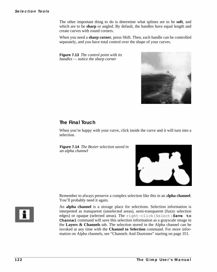
S e l e c t i o n To o l s
nd
ed
a
isection
inbe
351.
The other important thing to do is determine what splines are to besoft, andwhich are to besharp or angled. By default, the handles have equal length acreate curves with round corners.
When you need asharp corner, press Shift. Then, each handle can be controllseparately, and you have total control over the shape of your curves.
The Final TouchWhen you’re happy with your curve, click inside the curve and it will turn intoselection.
Remember to always preserve a complex selection like this in an alpha channel.You’ll probably need it again.
An alpha channel is a storage place for selections. Selection informationinterpreted as transparent (unselected areas), semi-transparent (fuzzy seledges) or opaque (selected areas). Theright-click|Select| Save toChannel command will save this selection information as a grayscale imagethe Layers & Channels tab. The selection stored in the Alpha channel caninvoked at any time with theChannel to Selectioncommand. For more infor-mation on Alpha channels, see “Channels And Duotones” starting on page
Figure 7.13 The control point with itshandles — notice the sharp corner
Figure 7.14 The Bezier selection saved inan alpha channel
1 2 2 T h e G i m p U s e r ’ s M a n u a l

C h a p t e r 7
t.
henthethe
cis-
theathe
ion.tinglec-
tect
ill
nt
OPTIONS
The options for the Bezier tool areAntialiasing andFeather. Read more aboutthem in “Selection Options” on page 116.
INTELLIGENT SCISSORS
The Intelligent Scissors tool is a very interesting piece of equipmenIt will guess the edges that you’re trying to select.
It’s quite hard to fully control theFree-hand tool, unless you’re extremely dex-terous. This is where Intelligent Scissors comes in. This tool lets you draw theout-line of an object, just like the Free-hand tool (you can be a bit sloppier), but wyou have defined your selection, it will automatically seek out the edges ofobject that you are trying to select. If it’s not a perfect selection, you haveoption to convert the Intelligent Scissors selection to aBeziercurve, and make thenecessary adjustments.
Sounds wonderful, doesn’t it? Sorry to say, the current version of Intelligent Ssors (Gimp v. 1.0) is not in full working order, but let us show you how it’ssup-posed to work when it’s functional again.
Open a Gimp image, make an IS selection around a clearly defined object inimage (like you would with the Free-hand tool). Hopefully, you’ll now havenearly perfect selection. If you want to adjust the IS selection, double-click onIS tool. This will bring up theIntelligent Scissors Options dialog. PressConvertto Bezier Curve and make the final adjustments.
Activation And ShortcutsYou may have noticed that there is nomarching ants borderin an IS selection. ISis just likeBezierselect — you have to click inside the shape to create a selectAfter you have activated your selection, all the usual selection shortcuts (creaunions, subtractions, intersections, etc.) work as they do with an ordinary setion.
OPTIONS
There are several options in the Intelligent Scissors option dialog: Edge-DeThresh. (for Threshold) and Elasticity are the most important ones.
• Edge-Detect Thresh. controls howsensitive Intelligent Scissors is tothe edges in your image. The higher the value, the more sensitive IS wbe.
• Elasticity controls howwilling IS is tobend away from the curve youhave drawn and snap to the edge.
These two options more or less control the entire functionality of IntelligeScissors.
If you’re using Gimp v.1.0.x, this feature is notfully developed, and willnot work very well.
T h e G i m p U s e r ’ s M a n u a l 1 2 3
S e l e c t i o n To o l s
nde ISe.
full
ted.
tione
it,
te anotert
to
For selecting solid objects with well-defined edges, you can set bothElasticityandEdge-Detect Thresh.to a high value, because there is only one edge, ayou want to make a quick and sloppy selection. The clear contours will enablto easily snap away from what you have “selected” to the edge of the squar
On the other hand, if you’re trying to select a certain edge in an image that isof edges, you have to be more careful in your drawing, and also lower theElas-ticity value so the section won’t snap to another edge than the one you wan
There are also a few other options.Curve resolution controls the roughness ofthe selection. If you have a lot of curves in your selection, a low curve resoluwill make the curvesroughor uneven. A higher curve resolution will make thcurves muchsmoother. Antialiasing andFeather work like they do for all theother selection tools.
USING UNDO WITH INTELLIGENT SCISSORS
An Intelligent Scissors drawing doesn’t turn into a selection until you click inand there are some advantages to this. You canUndo what you didbeforethe ISoperation without destroying your IS selection. After you have used IS to creaselection, but before enabling it, press Ctrl+Z to undo the previous action (butyour IS selection). When you’re finished, click inside the IS selection (or convto Bezier curves for further adjustment) to turn it into an active selection.
This will, for example, enable you to run some of theright-click|Fil-ters| Edge-Detect filters (see “Edge-Detect Filters” starting on page 485)enhance edges before you start using IS.
1 2 4 T h e G i m p U s e r ’ s M a n u a l


C H A P T E R
8 Paint ToolsTo be able to use the more advanced functions inGimp, you must first learn to control Gimp's basicpaint tools. You will soon find that you can achievemuch more using the basic paint tools than byapplying any of the instant paint filters.

Pa i n t To o l s
er
nyices.
spar-
u’llore
age
anML.
s anage
e
arek athe
THE COLOR PICKER
The color picker is used for choosing colors. If you don’t want to usany of thepalettes available (read more about palettes in “The ColoPicker” on page 128), you can just pick a color in your image or in a
other images that are currently open in Gimp, so you have many color choJust click on a color in an image, and this color will appear as theforeground orbackground color at the bottom of the toolbox.
THE COLOR INFORMATION WINDOW
A small information window shows theRGB and Alpha values (see “AlphaChannels” on page 353) of your chosen color.Alpha N/A means that your imagecontains no alpha channel (see “Alpha Channels” on page 353), or that tranency is not enabled. Invoke theAdd Alpha Channel command in theright-click|Image| Alpha menu or theright-click|Layers menu to addtransparency information to your image. Now, when you erase, cut or clear, yoget transparent areas instead of the background color in the toolbox. For minformation on alpha channels, see “Channels And Duotones” starting on p351.
TheHex Triplet is the color coded in hexadecimal. The hexadecimal format cbe used to set colors in web pages, because hex is used for coding color in HTFor aGrayscaleimage the information box displays anIntensity value rangingfrom 0 to 255, where 0 is black and 255 is white. An indexed image also haIndex number for the specific color. Note that the alpha value of an indexed imis either 0 or 255; there’s nothing in between.
OPTIONS
If you double-click on the Color Picker icon in the toolbox, you’ll access thColor Picker Options dialog. The only option is aSample Merged check-box. If the active layer isn’t opaque, or if it’s set to another Layer Mode thanNor-mal, the colors in the composite image will be different than the colors thatpresent in the layer. Check the Sample Merged checkbox if you want to piccolor that represents the color you see on the monitor, not just the color inactive layer.Only colors in visible layers are used.
Figure 8.1 Indexed, grayscale and RGB color info dialogs
1 2 8 T h e G i m p U s e r ’ s M a n u a l

C h a p t e r 8
n pal-
e ofreate
ind
ase
spe-
PALETTES
When you want to pick a color to work with, you can always use thecolorpicker, but most of the time you’ll be working with aColor Palette. You canchoose one of the many ready-made palettes, but you can also create your owette.
Another option is to create a palette from an indexed image usingright-click|Image| Save Palette . You can use a temporaryIndexed ColorPalette(if you’re using an indexed image) with the commandright-click|Dialogs| Indexed Palette .
CREATING A PERSONAL PALETTE
To create a personal palette, open theColor Palette (from the toolbox,File|Dialogs| Palette or press Ctrl+P). You’ll find aDefault palette in the pal-ette window, which contains some standard CMYK/RGB colors and a ranggrayscales. You can add colors to this or another custom palette, or you can cand name a new palette by selecting New from theOps menu.
To add colors from an image, drag the color picker over the image until you fa color you want to add to the palette (look in theforeground color square—you’ll see the colors change as you drag). When you’ve got the right color, releyour mouse button. Then, click on theNewbutton at the bottom of the Color Pal-ette dialog. The color square will appear on the palette. To add a color with a
Figure 8.2 The Color Picker Optionsdialog
Figure 8.3 The Color Palette
T h e G i m p U s e r ’ s M a n u a l 1 2 9

Pa i n t To o l s
theg
o useuaregage
n.
innd
th ar-
s,lor.
ose
eepyouon
cific RGB or HSV value, double-click in the foreground color square to accessColor Selection dialog. More information about the Color Selection dialobox is in “The Color Selection Dialog” on page 143.
You can name and save your new palette, and you can edit or delete colors. Tcolors in a palette, you don’t need to select them to the foreground color sqwith the picker — just click on a new color with whatever paint tool you’re usinat the time. More information about palettes can be found in “Palettes” on p176.
THE BUCKET FILL
This tool fills a selection with the currentforeground color. If youShift+click and use the Bucket tool, it will use thebackground colorinstead.
The Bucket tool will fill a layer that already contains color and alpha informatioThe amount of fill depends on whatFill Threshold you have specified.
The fill threshold determines how far the fill will spread (similar to the waywhich the magic wand works). The fill starts at the point where you click aspreads outward until the color or alpha value becomes “too different.”
BUCKET FILLING IN TRANSPARENT LAYERS
When you fill objects in a transparent layer (such as letters in a text layer) widifferent color than before, you may find that a border of the old color still surounds the objects. This is due to alow fill-thresholdin theBucket Fill optionsdialog. With a low threshold, the bucket tool won’t fill semi-transparent pixeland they will stand out against the fill because they have kept their original co
However, if you want to fill areas that are totally transparent, you have to choright-click|Select| Select All , and make sure that the layer’sKeep Trans button (in the Layers & Channels dialog) is unchecked. If the KTrans button is checked, only the opaque parts of the layer will be filled, and ifdon't use the Select All command, only the opaque “island” that you clicked
Figure 8.4 The Bucket Fill Optionsdialog
1 3 0 T h e G i m p U s e r ’ s M a n u a l

C h a p t e r 8
ers
gge
-
heill
beime,
ndtheoue the
w far
e,him-
will be filled. To read more about the layers and channel dialog read “The Lay& Channels Dialog” on page 317.
OPTIONS
TheFill Opacity slider allows you to set the transparency of the fill. The dialoalso includes aMode option (read more about modes in “Modes” starting on pa335).
Under Fill Type , the Pattern Fill radio button enables you to fill your selection with a pattern instead of a color. Use the commandsright-click|Dia-logs| Patterns or File|Dialogs| Patterns to open the Patterndialog, where you can choose a fill pattern.
Sample Mergedmeans that the bucket fill reacts to the color borders in tentire composite image, and not just the ones in the active layer (however, it wonly fill in the active layer).
Filling Feathered SelectionsIn a feathered selection, the bucket will make a soft concentric fill, which canmade more intense by clicking several times. If you use different colors each tthey’ll blend softly into each other in an opalescent effect.
THE BLEND TOOL OR GRADIENT FILL
This tool fills the selected area with a gradient blend of the foreground abackground colors by default, but there are many other options inGimp Blend tool. To make a blend, drag the cursor in the direction y
want the gradient to go, and release the mouse button when you feel you havright position and size of your blend. The softness of the blend depends on hoyou drag the cursor. The shorter the drag distance, the sharper it will be.
OPTIONS
Double-click on the Blend tool to see theBlend Options dialog.
The Blend tool has anOpacity option. Using a semi-transparent opacity valuand then dragging several times in different directions, gives an interesting smering, bubbly surface to a background.
T h e G i m p U s e r ’ s M a n u a l 1 3 1

Pa i n t To o l s
g-read
esomi-the
all
ated
G
enht
Tip: Also check out theDifference option in theMode menu, where doing thesame thing (even with full opacity) will result in fantastic swirling patterns, chaning and adding every time you drag the cursor. To understand Modes,“Modes” starting on page 335.
The Offset slider controls the fuzzyness of the blend. A high offset value giva harder, sharper blending edge, and the foreground color becomes more dnant. Offset moves the blend’s point of departure in the image (the point whereforeground color starts to blend with the background color). Offset works withgradient types,except for Linear and Shapeburst. Increase the offset value if youwant to control the appearance of fluorescent, shiny or metallic objects crewith the Blend tool.
The Blend Options dialog offers the standardRGB option, as well as theFG toBG (HSV) option (HSV stands forHue,Saturation andValue).
HSV GradientsHSV is a color model based on a 360-degreespectrum circle. This means thata gradient using an HSV blend will not simply make a transition from red F(foreground) to blue BG (background) via shades of violet.
HSV starts with red and follows the color circle clockwise through yellow, greand cyan until it reaches blue. The gradient will go clockwise if FG is in the rigpart of the semicircle, and counterclockwise if FG is in the left half.
Figure 8.5 The Blend Options dialog
1 3 2 T h e G i m p U s e r ’ s M a n u a l

C h a p t e r 8
lyaus-for
xt) or
FG to Transparent only uses one color for the gradient blend. It gradualchanges the alpha value (see “Alpha Channels” on page 353) from 255 to 0, cing the color to become increasingly transparent. This option is very usefulworking with softly blended collages or fog effects.
You can also choose to use one of the custom gradients (as described nemake your own gradient with the powerfulGradient Editor (right-click|Dialogs| Gradient Editor ).
GRADIENT TYPES
You can choose from nine different gradient types, as follows:
• The default gradient type isLinear, which produces a smooth lineartransition from one color to another.
Figure 8.6 HSV circle Figure 8.7 HSV gradient blendingfrom red FG to a red/magenta BG
Figure 8.8 Linear gradient
T h e G i m p U s e r ’ s M a n u a l 1 3 3

Pa i n t To o l s
thrag
• Bilinear mirrors a linear gradient blend. In other words, Bilinear placesthe FG color in the middle, and then makes the transition to BG color boways. The result often resembles metal pipes, especially if you only dfor a short distance.
• Radial, as the name implies, makes a radial transition from FG (in themiddle) to BG (peripheral). The radial gradient type is necessary forcertain gradients in the Gradient Editor, such as “Eyeball.”
Figure 8.9 Bilinear gradient
Figure 8.10 Radial gradient
1 3 4 T h e G i m p U s e r ’ s M a n u a l

C h a p t e r 8
ce
• TheSquare gradient produces a square blend, imitating the visualperspective of looking down a corridor.
• The effect of theConical (symmetric) andConical (asymmetric)gradients is like looking at a 3-D cone from above. The dragging distanis irrelevant for conical gradients. The two things that affect a conicalgradient arethe point of departure, which determines where the top of thecone is placed, and thedrag direction, which determines from where theFG color (which represents light or shadow) is coming.
Conical (symmetric)creates a cone with an even shape.
Figure 8.11 Square gradient
Figure 8.12 Conical symmetricgradient
T h e G i m p U s e r ’ s M a n u a l 1 3 5

Pa i n t To o l s
e
.w.
ats.ith a
TheConical (asymmetric) gradient imitates a “drop shaped” cone, i.e., acone with one sharp edge.
• Shapeburst gradients give a three-dimensional look to a defined shapor selection. Shapeburst gradients are not affected by drag direction,distance or position.Spherical gives a flatter, rounder looking surfacethan angular or dimpled (which produces a sharp topographic surface)You can see examples of the different shapeburst gradients here belo
The Repeat options (Sawtooth wave and Triangular wave) allow you torepeat a gradient fill. The shorter the drag distance, the more often the fill repeThe examples below show the sawtooth and triangular repeating options wlinear gradient.
Note: Repeat can’t be used with Conical or Shapeburst gradients.
Figure 8.13 Conical asymmetricgradient
Figure 8.14 Spherical Figure 8.15 Angular Figure 8.16 Dimpled
1 3 6 T h e G i m p U s e r ’ s M a n u a l
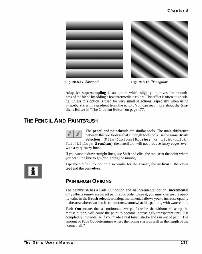
C h a p t e r 8
-sub-sing
n
ere
pac-tylor.
theit isThef the
Adaptive supersampling is an option which slightly improves the smoothness of the blend by adding a few intermediate colors. The effect is often quitetle, unless this option is used for very small selections (especially when uShapeburst), with a gradient from the editor. You can read more about theGra-dient Editor in “The Gradient Editor” on page 177.
THE PENCIL AND PAINTBRUSH
The pencil andpaintbrush are similar tools. The main differencebetween the two tools is that although both tools use the sameBrushSelection (File|Dialogs| Brushes or right-click|
File|Dialogs| Brushes ), the pencil tool will not produce fuzzy edges, evewith a very fuzzy brush.
If you want to draw straight lines, use Shift and click the mouse at the point whyou want the line to go (don’t drag the mouse).
Tip: the Shift+click option also works for theeraser, the airbrush , the clonetool and theconvolver.
PAINTBRUSH OPTIONS
The paintbrush has a Fade Out option and an Incremental option.Incrementalonly affects semi-transparent paint, so in order to see it, you must change the oity value in theBrush selectiondialog. Incremental allows you to increase opaciin the area where two brush strokes cross, somewhat like painting with waterco
Fade Out means that a continuous sweep of the brush, without releasingmouse button, will cause the paint to become increasingly transparent untilcompletely invisible, as if you made a real brush stroke and ran out of paint.amount of Fade Out determines where the fading starts as well as the length o“comet tail.”
Figure 8.17 Sawtooth Figure 8.18 Triangular
T h e G i m p U s e r ’ s M a n u a l 1 3 7
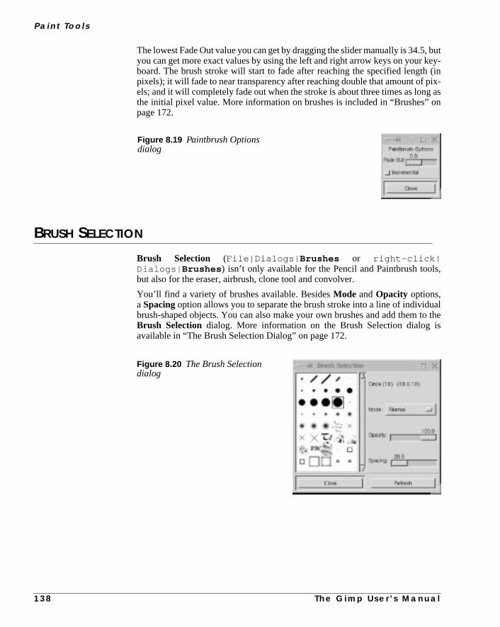
Pa i n t To o l s
, butkey-
(inpix-g ason
s,
alto theis
The lowest Fade Out value you can get by dragging the slider manually is 34.5you can get more exact values by using the left and right arrow keys on yourboard. The brush stroke will start to fade after reaching the specified lengthpixels); it will fade to near transparency after reaching double that amount ofels; and it will completely fade out when the stroke is about three times as lonthe initial pixel value. More information on brushes is included in “Brushes”page 172.
BRUSH SELECTION
Brush Selection (File|Dialogs| Brushes or right-click|Dialogs| Brushes ) isn’t only available for the Pencil and Paintbrush toolbut also for the eraser, airbrush, clone tool and convolver.
You’ll find a variety of brushes available. BesidesMode andOpacity options,aSpacingoption allows you to separate the brush stroke into a line of individubrush-shaped objects. You can also make your own brushes and add themBrush Selection dialog. More information on the Brush Selection dialogavailable in “The Brush Selection Dialog” on page 172.
Figure 8.19 Paintbrush Optionsdialog
Figure 8.20 The Brush Selectiondialog
1 3 8 T h e G i m p U s e r ’ s M a n u a l

C h a p t e r 8
u toat like
ound
nels”can,ith
ce it,
f theou
are
o-alue,rush
THE ERASER TOOL
Just as you can paint with pattern-shaped brushes, you can alsoerasewiththe same patterns. This is a great way to create convincingtextureeffects, especially if you use it in many layers. TheIncremental option is
only effective when the brush opacity is less than 100. Incremental allows yoincrease transparency in the area where two brush strokes cross, somewhadding more water to a watercolor painting. TheHard edgeoption removes fuzzyedges on all brush types (like the Pencil tool).
Tip: To isolate a complex selection, use the Eraser tool to erase the backgraround the object’s outline, then use thewand or lassoto easily select either theobject or the surroundings and delete or cut them away.
HINTS
You can change the size and shape ofFloating selectionswith the eraser tool.This happens because the eraser tool affects alpha values (see “Alpha Chanon page 353), and those values determine the area of a floating selection. Youfor example, reduce the selection by trimming its edges or cutting holes in it wthe eraser tool. If you’d rather increase the floating selection area than reduyou can do this by choosingright-click|Select| Invert before floating.That way, you’ll trim the surrounding areas instead, thus increasing the size ooriginal float. To re-select the old float (which you have now added parts to) yjust invert it back again, using the same command.
THE AIRBRUSH TOOL
Theairbrush tool creates soft, semi-transparent spray strokes. Theretwo options in the Options dialog:Rate andPressure. TheRate valuedetermines how spray distribution follows movement. A low value pr
duces a smooth, even brush stroke (pausing does not affect it). With a high vthis tool behaves more like a real airbrush: If you pause in mid-stroke, the airbwill keep on spraying and leave a darker stain at that position.
Figure 8.21 The Eraser Optionsdialog
T h e G i m p U s e r ’ s M a n u a l 1 3 9

Pa i n t To o l s
ure“air-high
ee
nthe
fs thethethernt
rd,eg-
Pressureregulates how much paint there is in the “spray.” Note that low pressisn’t the same as low opacity on the brush. Low pressure is more uneven (orbrushy” looking) compared to the smoother appearance that results frompressure and low brush opacity.
THE CLONE TOOL
TheClone tool gives you the ability to paint withpatternsor with partsof an imageinstead of just a solid color. To paint with a pattern from thPattern Selectiondialog (see “Palettes” on page 176), simply click on th
pattern you want and start painting.
CLONE OPTIONS
Use theAligned option if you want a continuous pattern. If the Aligned optiois not checked, you will paint a new part of the pattern every time you let go ofmouse button and start again.
If you use theImage Sourceoption, note that in Gimp you use Ctrl instead oAlt (Photoshop) to choose the point of departure from the image source. PresCtrl key and click on the part of the image that you want to clone, return toimage you wish to retouch and start cloning. You can choose to clone from anopart of your image, from one layer to another or from a completely differeimage.
Retouching HintsNeedless to say, theClone tool is the ultimateretouching instrument. Forexample, if you would like to retouch a birthmark from a face, it would be haalmost impossible, to imitate the complex color varieties of skin texture with r
Figure 8.22 The Airbrush Options dialog
Figure 8.23 The Clone Tool Optionsdialog
1 4 0 T h e G i m p U s e r ’ s M a n u a l

C h a p t e r 8
ayok
ntodes.
ou useingolor.
rd;
ular paint or blends. The cloning of skin in another part of the face is the only wto make it look good. We’re not saying that cloning is easy, though; to make it loconvincing you may well have to clone from different directions, with differebrushes, and maybe even in different layers with appropriate opacities and m
THE CONVOLVER
The Convolver tool allows you to blur or sharpen your image.Pres-sure regulates the strength of the convolve effect.
CONVOLVER BLUR
The convolver’sBlur option is somewhat similar toSmudgein Photoshop,though not quite as smeary. It softens sharp edges and blurs whole areas as yit. The blurring effect always produces a darker color than the original. Blurrtransparent areas with the convolver will transform those areas to an opaque cThe convolver tool will use the nearest color and smear it to full opacity.
CONVOLVER SHARPEN
TheSharpenoption doesn’t really sharpen in the traditional sense of the woits effects are too “dotty” or “pixelly.”
Figure 8.24 The Convolver Optionsdialog
Figure 8.25 The original image and the blurred one
T h e G i m p U s e r ’ s M a n u a l 1 4 1

Pa i n t To o l s
ebling
on353),
rs.theas
If you want to sharpen something that is out of focus, you should useright-click|Filters|Enhance| Sharpen or right-click|Filters|Enhance| Unsharp Mask . However, the convolver’s Sharpen will producsome very interesting graphic results (especially in a grayscale image) resemengravings, prints or ink drawings.
THE FOREGROUND/BACKGROUND ICONS
The foreground/background color selector is at the bottom of thetoolbox. Theforegroundcolor is the color with which you paint orbucket fill. Thebackgroundcolor is the color you’ll get if youerase,
cut or edit/fill a piece of your image. Note that if you perform these operationsan image that contains an alpha channel (see “Alpha Channels” on pageyou’ll get transparency instead of the background color.
Pressing thedouble arrow symbol swaps the foreground and background coloYou can also swap the colors by pressing X, or you can choose to restoredefault values (Black/White) with D (the mouse cursor must be in your imageyou use these shortcuts).
Figure 8.26 The sharpenedimage
1 4 2 T h e G i m p U s e r ’ s M a n u a l

C h a p t e r 8
olorft to
theel for
hedh
coloran-
ider.sonot
THE COLOR SELECTION DIALOG
Double-clicking on theforeground or the background icon brings up theColor Selection dialog, where you can easily change to another color.
You can change the color manually, by clicking on a hue in the spectrum cfield to the right, and then dragging the cross in the large color box on the lethe exact color you want.
If you want a specific RGB or HSV color, you can type the exact value in theHSVor RGB parameter fields, or you can drag the sliders to specify a color.
TheH (Hue) channel is displayed in the color fields by default when you openColor Selection dialog. However, you can choose to search in another channthe color you want. If you’d like a pastel or neon color, you can click on theS(Sat-uration) radio button to search by saturation instead of by hue. If you want wasout or gloomy colors, click on theV (Value) radio button. You can also searcusing theR (Red),G (Green) orB (Blue) channels to find the shade you want.
When you search in another channel than the Hue channel, the spectrumfield will change into a smooth gradient, where you specify an approximate chnel value. Clicking in this gradient is the same thing as dragging the channel slThe large color box will then display all colors with this specific channel value,dragging the cross will change the value of all the other channels, but it willaffect the value of the selected channel.
Figure 8.27 TheColor Selection dialog
T h e G i m p U s e r ’ s M a n u a l 1 4 3
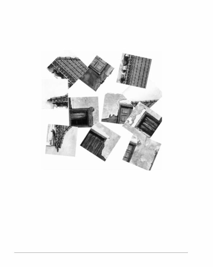

C H A P T E R
9 Edit And ViewThis chapter covers the basic functions found in theEdit and View menus. Some of these functions arewell-known to users of similar software, but somefeatures are quite unique to Gimp.

E d i t A n d V i ew
ro-cal
d
most
youad
ge
firsthapeto
e there
agecopy
nd
om-
fortion
the
ved.
CUT, COPY AND PASTE
These three commands (all located on theright-click|Edit menu) are socommon that they shouldn’t need much explanation. As with ordinary word pcessing, cutting and copying a part of an image will place that selection in a lobuffer . When you choosePaste, Gimp takes that selection from the buffer anturns it into afloating selection, which you can eitheranchor to a layer, or putinto a layer of its own.
Note that the default shortcut keys for these commands are the same as inWindows programs: Ctrl+x forCut, Ctrl+c forCopy and Ctrl+v forPaste.
You may have noticed the fantastic possibilities ofdynamic key bindings inGimp. If you don’t like the default settings, you can choose any shortcut keylike for a certain command by simply typing the new shortcut in the menu! Remore about it in “Default Shortcuts And Dynamic Key Bindings” starting on pa9.
PASTE INTO
Right-click|Edit| Paste Into is a very useful command when youwant to insert an image into a defined shape in another image. To use it, youneed to copy or cut the image you want to paste. Then, you make a selection sin the target image (if you use a little feather, you’ll get wonderfully soft edgesyour selection). Choose Paste Into and the image you copied will appear insidselection. Click on theMove tool and you can place the selection exactly wheyou want it, before you anchor it by clicking elsewhere on the image.
CUT, COPY AND PASTE NAMED
You’re probably accustomed to being able to cut/copy and paste only one imat a time. In other words, as soon as you copy or cut something new, the oldwill be replaced by the new one.
Cut Named, Copy Named and Paste Namedallow you to use abuffer thatcan hold a great number of cut images. If you’re repetitively cutting/copying apasting a lot of images, this is an extremely convenient feature.
Select an image or part of an image that you want to cut or copy. Select the cmand right-click|Edit| Copy Named or right-click|Edit|Cut Named. A small dialog box pops up and prompts you to enter a nameyour selection. After you enter a name and click on the OK button, your selecwill be placed in a buffer.
When you want to paste one of the selections you have named and put innamed buffer, chooseright-click|Edit| Paste Named . This com-mand brings up a dialog which displays a list of all the selections you have saTo paste a selection, just choose its name and pressPaste, and your selection willappear as a floating selection in the active image.
1 4 6 T h e G i m p U s e r ’ s M a n u a l

C h a p t e r 9
t toyour
tion
ehe
Note: The named buffer only exists as long as your Gimp session. If you wansave a selection more permanently, you need to save it in a separate layer inimage.
The optionReplace Current Selectionallows you to replace a non-floatingselection in the image with a selection from your list. Replace Current Selecunchecked gives the same result asPaste Into, if you already have a selection inthe image. If you try to use this option with a floating selection, the float will banchored to the image. The selection from your list will turn into a new float in tsame place as the old one.
You can also delete a selection from the list if you no longer need it.
Figure 9.1 The Paste Named Buffer dialog
Figure 9.2 These images were created using Cut, Copy and Paste Named.
T h e G i m p U s e r ’ s M a n u a l 1 4 7

E d i t A n d V i ew
ills the
op-All
rs
upy
ingm toou
PASTE AS NEW IMAGE
This is a very useful function. When you applyright-click|Edit| Pasteas New Image to a selection, the image information within the selection wbe copied and pasted into a new image with the same size and proportions aselection. The selection itself will also be copied.
If your image has several layers, all layers present within the selection will be cied into the new image (small layers outside the section will not be copied).layer information such asvisible layers, grouped layers, layer masks andalpha channelswill also be copied to the new image. To learn more about layeread “Layers And Floating Selections” starting on page 315.
COPY VISIBLE
Right-click|Edit| Copy Visible will copy all visible layers to a flatcopy which you can paste into a new image. It’s like executing bothCopy andMerge visible layersat the same time. This function is quite handy when yodon’t want to alter the original layers, but only work with a quick copy. The cocan then be pasted into a new image.
MULTISELECT
The right-click|View| Multiselect function is used to break up animage into several smaller images. This is ideal for preparing your work for bepublished on the Internet, since web graphics are often cut up in a grid systemake them fit in an HTML table. Before invoking the Multiselect command, ymust prepare the image by draggingguides(See “Rulers And Guides” on page151) to the exact position where you want the image to be partitioned off.
Figure 9.3 The image is readyto be cut up by Multiselect; notethe guides
1 4 8 T h e G i m p U s e r ’ s M a n u a l
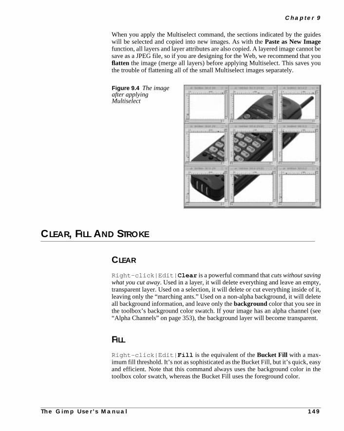
C h a p t e r 9
ides
ot bet youou
ty,f it,ete
(seeent.
sythe
When you apply the Multiselect command, the sections indicated by the guwill be selected and copied into new images. As with thePaste as New Imagefunction, all layers and layer attributes are also copied. A layered image cannsave as a JPEG file, so if you are designing for the Web, we recommend thaflatten the image (merge all layers) before applying Multiselect. This saves ythe trouble of flattening all of the small Multiselect images separately.
CLEAR, FILL AND STROKE
CLEAR
Right-click|Edit| Clear is a powerful command thatcuts without savingwhat you cut away. Used in a layer, it will delete everything and leave an emptransparent layer. Used on a selection, it will delete or cut everything inside oleaving only the “marching ants.” Used on a non-alpha background, it will delall background information, and leave only thebackground color that you see inthe toolbox’s background color swatch. If your image has an alpha channel“Alpha Channels” on page 353), the background layer will become transpar
FILL
Right-click|Edit| Fill is the equivalent of theBucket Fill with a max-imum fill threshold. It’s not as sophisticated as the Bucket Fill, but it’s quick, eaand efficient. Note that this command always uses the background color intoolbox color swatch, whereas the Bucket Fill uses the foreground color.
Figure 9.4 The imageafter applyingMultiselect
T h e G i m p U s e r ’ s M a n u a l 1 4 9

E d i t A n d V i ew
tions
s by
dg-tton.he
the
ords,
STROKE
Right-click|Edit| Stroke creates acolored edgearound the selection.This edge, or contour, is based on what brush you’re using and what brush opyou have set in theBrush Selection dialog. Stroke can be used for creatingsimple drawings from selection shapes, or for manipulating selection edgeusing Stroke with different artistic brushes and different settings forSpacing,Mode andOpacity.
ZOOM
If the Magnify tool is active, you can click in an image to zoom in, anShift+click to zoom out. To zoom a specific part of the image, drag diaonally across that part (draw a rectangle), and release the mouse bu
You can alsopan a zoomed image by clicking and dragging on the image with tmiddle mouse button.
Even if the Magnify tool is not active, you can zoom with theright-click|View| Zoom in and right-click|View| Zoom out commands. Thedefault keyboard hotkeys are- (the minus sign or hyphen) forZoom out and=(the equal sign) forZoom in. Since Gimp supportsdynamic key bindings,you can change = to + (the plus sign), if you like that better. Pressing1 on yourkeyboard will return the view to 1:1 scale.
The right-click|View| Zoom command allows you to choose from ninedifferent zoom scales: 16:1, 8:1, 4:1, 2:1, 1:1, 1:2, 1:4, 1:8 and 1:16. 16:1 islower limit and 1:16 is the upper limit for zooming in Gimp.
Pressing - zooms in smaller steps than zooming using the scales. In other wto display your image in a scale of 1:3, press- three times.
Figure 9.5 This example was createdwith Stroke using the swan brush
1 5 0 T h e G i m p U s e r ’ s M a n u a l

C h a p t e r 9
heard-for
side
t sethere-
S”es infi-
s.s by
antotion.on
the
MAGNIFY OPTIONS
Allow Window Resizing means that the canvas size will always adapt to tamount of zoom you use, so you’ll always be able to see the entire image regless of zoom level. If you don’t want to use this option, you can press Ctrl+eShrink Wrap , which will also adjust the canvas to the image size.
RULERS AND GUIDES
RULERS
At the top and left sides of the image frame, you’ll see the Gimprulers. As youdrag the cursor over an image, a horizontal and a vertical arrow will appear inthe rulers, showing the current cursor position.
In Gimp, all images are measured inpixels by default, so the ruler unit is pixels.You can change the ruler unit to millimeters or inches by editing your.gimp|gimprc file (see “Gimp Start Flags And rcfiles” starting on page 785).
However, there is not much point in doing so, because in Gimp v.1.0 you can’image resolution and canvas size the way you can in Photoshop. Size (and tfore resolution) for a printed image is determined by thePrint dialog orSave as(Postscript)dialog (see “Printing Images” on page 96 and “PostScript And EPon page 91). The reason for this is that Gimp is hard coded to handle all imag72 ppi (dpi) which is the default for things like web images, but is quite insufcient for printing.
GUIDES
Horizontal and verticalguidescan be dragged straight from the left or top rulerYou can easily adapt the size, shape and position of a selection to the guidedrawing it within the frame of two vertical and two horizontal guides.
You can also use the guides to set the exact point of origin from which you wa selection to start. If you press theCtrl key and start dragging close enough tthe point where the guides cross, that spot will be the center of the new selecWithoutCtrl , the selection will start from the cross and continue in the directiyou drag.
To change the position of a guide, use theMove tool. Notice how the move cur-sor symbol changes into a pointing hand when it touches a guide, and thatguides will change color from blue to red when they are touched.
Figure 9.6 The Zoom Options dialog
T h e G i m p U s e r ’ s M a n u a l 1 5 1

E d i t A n d V i ew
cally
ith
you
ttchso
pearr-
TOGGLE AND SNAP
Right-click|View| Snap To Guides is enabled by default. If this optionis checked, moving any kind of selection close enough to the guides automaticauses the selection to “stick” or snap to the guides.
If you don’t want to use guides and/or rulers, they can be toggled on and off wthe right-click|View| Toggle Guides or right-click|View|Toggle Rulers commands.
UNDO AND REDO
These options should be self-explanatory. Because you’ll use them often,should learn their keyboard shortcuts by heart. The shortcut forright-click|Edit| Undo is Ctrl+z and the shortcut forright-click|Edit| Redo isCtrl+r.
NEW VIEW, SHRINK WRAP AND WINDOW INFO
NEW VIEW
The right-click|View| New View command opens a new window thadisplays the same image you’re currently working on. This enables you to wayour creation from several windows, each with different focus and zoom if youdesire. However, it is still the same picture, and the changes you make will apin all of the New View windows. If you want to try out different versions of youimage, press Ctrl+d toDuplicate. Unlike New View, duplicate windows are sep
Figure 9.7 A screen shot of twoguides dragged into the drawingarea from the horizontal andvertical rulers
1 5 2 T h e G i m p U s e r ’ s M a n u a l

C h a p t e r 9
dow
ddlessthe
).
arate, changeable copies of your original image. Changes made in one winwon’t appear in the other windows.
SHRINK WRAP
Right-click|View| Shrink Wrap will cause the canvas size to expanor shrink based on your zoom, so you’ll be able to see the entire image regarof zoom level. If you want this to happen automatically every time you changezoom level, click onAllow Window Resizing in the Magnify tool optionsdialog (double-click on the Magnify tool to display the Magnify tool options dialog
WINDOW INFO
The Window Info dialog (right-click|View| Window Info ) dis-plays up-to-date information on the active window, such asDimensions, ScaleRatio andDisplay Type.
Figure 9.8 The Window Info dialog
T h e G i m p U s e r ’ s M a n u a l 1 5 3


C H A P T E R
10 Transform ToolsIn this chapter, we’ll take a look at the differenttransform tools, including the Move tool and theCrop tool.

T r a n s fo r m To o l s
gting
laysion
e awilla sec-
therto
he
ing
ove
theusedot
ngayer
see
THE MOVE TOOL
The Move tool can move the entire image or layer, guides, floatinselections or empty selection shapes. Please read “Layers And FloaSelections” on page 315 for information about layers.
MOVING WITHOUT USING THE MOVE TOOL
In “Selection Tools” starting on page 109 we discussed the fact that Gimp dispamove symbolwhen you move your cursor over a selection, although a selecttool (and not the Move tool) is active.
If you move your selection using this move symbol, the selection will becomfloating selection. You can only move it once, because the move symboldisappear as soon as you let go of the mouse button. To move your selectionond time, you must switch to the Move tool.
You can also ignore the selection tool’s move symbol and go straight toright-click|Select| Float command. This procedure will make youselection float without moving it from its current position. Should you decidemove it, you can use the Move tool in the normal way.
MOVING FLOATING SELECTIONS
When you use the Move tool on a floating selection, you’ll notice that tdouble-arrow symbol becomes asingle arrow when the pointer is outside ofthe selection. If you click your mouse when the single arrow is visible, the floatselection willanchor to (merge with) the layer that was last active.
MOVING THE ENTIRE IMAGE OR A SINGLE LAYER
If you don’t have a selection, the Move tool will move theentire imageoutsidethe drawable area. If your image has more than one layer, the Move tool will mtheactive layer.
Moving Transparent LayersThe Move tool can’t move an empty, transparent layer. If you try to do that,Move tool will move the top layer in the layer stack instead! This happens becathe Move tool needs something solid to grab onto. Of course, you could paint aof color in the empty layer, turn off all the other layers (see “Layers And FloatiSelections” starting on page 315) and then move the layer (by grabbing the lby the dot), but this isn’t a very convenient technique.
The solution to this problem is to press the Shift key as you drag. When youthe yellow layer boundary turn blue, you’ll know for sure that you’re movingthe right layer.
1 5 6 T h e G i m p U s e r ’ s M a n u a l

C h a p t e r 1 0
m-to
ovefor
youion
ith
elec-c-
keyse Alt
ool,
Moving Grouped LayersAlso notice that if you havegrouped one or more layers (with the little anchorsymbol), they’ll all move, regardless of which layer is currently active. For exaple, if you have grouped a text layer with a drop shadow layer, you’ll haveungroup them or merge them before moving another layer, otherwise you’ll mall three layers. See “Layers And Floating Selections” starting on page 315more information on working with layers.
MOVING EMPTY SELECTIONS
If you just want to adjust the position of a selection area, press the Alt key asmove the selection. With this technique, only the empty form of the selectmoves, and not the contents.
Note that this option only works for the normal (empty) selections you make wa selection tool. You can never move a floating selection using the Alt key.
This option allows you to use the selection as a template: You can move the stion around and fill it every time you move it. Note that the Move tool or a seletion tool must be active for this technique to work.
HintsThe Move tool has an extra feature that allows you tonudge(move in small, pre-cise increments) a floating selection or a layer with the keyboard’sarrow keyswhen the Move tool is active. Pressing the Shift key as you press the arrowwill increase the length of these steps. To nudge an empty selection, press thkey and the arrow keys.
Note that when you make multiple selects, Gimp treats them as aunit . Thatmeans that you can’t move one selection closer to another with the Move tbecause all of the selected areas will move together as one.
Figure 10.1 Duplicating astar shape by moving a selection
T h e G i m p U s e r ’ s M a n u a l 1 5 7

1 5 8
Tr a n s fo r m To o l s
opthe
andr
re bythe
ard.is
n
lec-ose
THE CROP TOOL
TheCrop tool corresponds to the “scissors” in Photoshop. You can cran image if you just want a part of the picture. To crop, click and dragmarquee diagonally. Release the mouse button when you are satisfiedthe Crop Information dialog box will appear. See the next section fo
more information on the dialog box.
The cropmarks can be placed very accurately. You can move the crop squadragging on the lower-left or upper-right corners, or resize it by dragging onupper-left or lower-right corners.
You can also move (nudge) the crop area using the arrow keys on your keyboAlternatively, you can setguides(make sure that the Snap To Guides checkboxchecked in theright-click| View menu) to position the crop area.
Press theCrop button in the toolbox, or click inside the markings, and the portioof the image inside the cropmarks will be your new image.
THE CROP INFORMATION DIALOG
This dialog displays the crop area’sX andY Origins andWidth andHeight inpixels. If you have created a selection in your image, you can click on the Setion button in the dialog box. This will automatically place the crop area as clas possible to your selection.
Figure 10.2 Screen shot showingthe Crop tool in action
Figure 10.3 The Crop Information dialog
T h e G i m p U s e r ’ s M a n u a l

C h a p t e r 1 0
ia-
a, so
owcanthe
ou
tthegree
THE TRANSFORM TOOL
TheTransform tool is much like the “Effects” menu in Photoshop.Double-click on the Transform tool to see the Transform Tool Options dlog box, where you can choose whether you want torotate, scale, shear
or distort a selection.
ROTATE
When you’re transforming usingRotation, you drag the mouse to rotate theselection. Note that parts of the image will end up outside the drawable areyou may have to resize the image afterward.
As you use the mouse to rotate the image, therotation angle will be displayedin a small dialog box. You can’t insert numbers into the dialog; it just displays hmuch you’ve rotated the image (this is not a very precise tool). However, youpress theCtrl key and drag on the image with your mouse, which makesselection rotate in 15 degree increments.
If you want to rotate a layer or image 90 or 270 degrees (for example, if yscanned an image in portrait mode and you want landscape) theright-click|Image|Transforms| Rotate option is a better choice.
If you need to specify the exact rotation angle, use the right-click|Layers|Transforms| Rotate Any Angle option. Note that you can’t get exacvalues by just dragging the slide bar in the Rotate Any Angle dialog. Clickmouse button to the left or right of the slider to change the angle in one deincrements for every click.
Figure 10.4 Screen shotshowing that you may needto resize the image afterrotating it
Figure 10.5 The rotation angledialog
T h e G i m p U s e r ’ s M a n u a l 1 5 9

T r a n s fo r m To o l s
ero-
he
.
In
SCALE
ChooseScaling from the Transform Tool Options dialog and then click on thimage to see the Scaling Information dialog. The Scaling Information dialog pvides you with information on both theOriginal Height andOriginal Widthof the selection, as well as theCurrent Width andCurrent Height .
Drag on the image with your mouse to scale the image. TheX Scale RatioandY Scale Ratiotell you how much you’ve altered the size and proportions of toriginal image.
The Ctrl key locks the scale’sX axis, so you can only affect the height of theimage. Shift locks theY axis, so you can only affect the width of the imageCtrl+Shift forces the image to scale proportionally .
SHEARING
Shearing willdeforman image in either the horizontal or the vertical plane.other words, it will turn a rectangle into a parallelogram.
Figure 10.6 The Scaling informationdialog
Figure 10.7 Screen shot of adownscaled image
Figure 10.8 The Shear info dialog
1 6 0 T h e G i m p U s e r ’ s M a n u a l

C h a p t e r 1 0
n
tion,er ofni-
tool
ation
-ular
Click on theShearingoption in the Transform Tool Options dialog, then click oyour image to see theShear Information dialog. Shear your image by click-ing and dragging on the corners. Dragging up and down shears in the Y direcand dragging on the sides shears in the X direction. You can shear along eiththe X or Y axes, but only on one at a time. In other words, if the X Shear Magtude is other than zero, then the Y Shear Magnitude must be zero.
Tip: If you want to shear a selection both ways, you have to change to anothericon, and then return to Transform.
PERSPECTIVE
The last option on the Transform Tool Options dialog isPerspective. The termperspective isn’t quite accurate, because no actual perspective transformtakes place (making the image small in the far end and large in the other).
It is better described as adistortiveeffect, since you can move all four displacement points (the corners) independently. You can certainly make a rectangselection look like a perspective, but you have to do that manually.
Figure 10.9 A screen shot of Shearin action
Figure 10.10 A screen shot showingPerspective in action
T h e G i m p U s e r ’ s M a n u a l 1 6 1

T r a n s fo r m To o l s
hench
an’tges.you
n
Observe that you can turn the “perspective” inside out if you like. If you let tlines of the perspective square cross or top each other, you’ll mirror and wrethe selection so much it will eventually become unrecognizable.
Transform SmoothingOn the Transform Tool Options dialog, the Smoothing checkbox providesantialiasing option, which will make distorted edges look better. If you donuse Smoothing, your selection might turn out very rough and pixly on the edOn the other hand, the Smoothing option can make edges very blurry, soshould take that into consideration as well.
THE FLIP TOOL
On the toolbox, the Flip tool does exactly that — itflips the image, ormore accurately — the Flip toolmirrors the selectionhorizontally orvertically . If you are working with an image where you want the illusio
of reflection (whether in water, glass or metal), this is the tool to use.
THE MAGNIFY TOOL
Please turn to “Zoom” on page 150.
Figure 10.11 The Transform ToolOptions dialog
1 6 2 T h e G i m p U s e r ’ s M a n u a l


C H A P T E R
11 Text And FontsGimp’s support for text is based on how the XWindow System manages fonts.

Tex t A n d F o n t s
enxts if
stthe
textvethe
anTo
ver,text
uree
he
lledt”
THE TEXT TOOL
To insert text in a Gimp image, click on theText tool in the toolbox andthen click at a spot inside the image. The Text Tool dialog box will opand display a list of the installed fonts. Type in the text you want in the te
box in the bottom of the dialog. Click on the font you want, set the parameteryou want to change the default values and click OK.
Now your text string will appear as afloating selectionin your image. The textwill have the same color as theforeground color in the toolbox. If for some rea-son you aren’t happy with the text — if it’s too small, too large or if the font judoesn’t look right — you can delete the floating text selection by pressingcross (Delete Layer) button in theLayers & Channel dialog.
MOVING AND ANCHORING TEXT
To move the text selection to another position, place the cursor on top of theso that themove symbolappears, then click and drag the text. You can moand drop the text as many times as you like, and you don’t have to switch toMove tool.
When you’re satisfied with the position of the text, you have two options. You ceither anchor the text to the last active layer, or place it in a layer of its own.merge the text with the image, press theAnchor Layer button in theLayers &Channelsdialog. To create a text layer, press theNew Layer button or double-click on theFloating selection icon bar.
Once you’ve anchored the text to the image, you can’t edit it anymore. Howeif you choose to place it in a transparent text layer, it’s easy to move the entirelayer with the Move tool.
CHANGING THE TEXT COLOR
It is also simple to change the color of the letters in a text layer. First, make sthat the Keep Transp. radio button is checked in the text layer. Choosright-click|Select| All , click in the foreground color field in the tool-box to access theColor Selectiondialog and choose another color. Then select tBucket fill tool and click in the layer.
Tip: If you want to be able to edit the text, you should use a great plug-in caDynamic Text instead of the Text tool. Read about this plug-in in “Dynamic Texon page 588.
1 6 6 T h e G i m p U s e r ’ s M a n u a l

C h a p t e r 1 1
Axels
ize of
xelstion
oints90
e,
ften
hisdis-
esualt sim-withow
OPTIONS
At the top of the Text tool dialog, the currentText Size is shown in eitherpix-els or points (you can choose which you prefer from the pull-down menu).pixel is the smallest component in a bitmap image, and all measures in pidepend on thescreen resolution. A point, however, is a fixed value — one inchis the same as 72 points.
Points are used to measure fonts. For example, 12 points is the standard sbody text in most word processing programs.
Standard screen resolution is often 72 pixels per inch, in which case text in piwill be the same size as text measured in points. However, on a high-resoluscreen, such as one with a resolution of 90 pixels per inch, setting the text to pwill render a larger text than setting the text to pixels. For example, there arepixels for every 72 points, so a text size of 50 points will be 63 pixels widbecause there are 1.25 pixels for every point.
Antialiasing is an effect used to smooth edges in bitmapped images. It is oused on artistic text, because it softens thejaggies(the jagged pixel edges of theletter’s curves in low resolution). It will blur the edge pixels to transparency. Twill make curves look smoother, but the edges will become unsharp and lesstinctive.
The Font list displays all fonts installed on the local X server. Click the namof a font to change the text in the text box. Note that some of the more unufonts (such as Chinese or Japanese fonts) may bring X to a near-crashing halply because so many characters are involved. As a rule, be careful using fontsAsian names, or avoid them entirely. To learn how to install new fonts, read “HTo Get Fonts To Gimp” starting on page 759.
FONT PARAMETERS
There are eight font parameters (Foundry, Weight, Slant, Set width, Spac-ing, Registry, Encoding andBorder) in the Text Tool dialog box.
T h e G i m p U s e r ’ s M a n u a l 1 6 7

Tex t A n d F o n t s
-rentwnver-
ou
.
r-er-
FoundryFoundry refers to theorigin of your font (usually the manufacturer). This parameter has to distinguish different fonts with the same name that are from diffecompanies. This is important, because many different versions of well-knofonts exist and you need to specify which one you mean if you have severalsions installed.
WeightWeight shows what typographic “blackness” options you have for the font yhave chosen (black, bold, demibold, mediumand regular). Options that aren’tavailable for the chosen font are grayed out.
SlantSlant is the “posture” option. The letterr (Roman) signifiesuprightposture. Theletters i (italic ) or o (oblique) are two differentslantedpostures.i produces agood representation of the letters ando gives a simpler, more jagged italic typeThe available posture depends on the font.
Set WidthThis is an option if your font includes the built-in possibility of modifying the hoizontal width. Sometimes, the same font will come in wider and narrower vsions, typically calledblack, semi-condensed andnarrow.
Figure 11.1 The Text tooldialog
1 6 8 T h e G i m p U s e r ’ s M a n u a l

C h a p t e r 1 1
nts,s arenott of
therTo
you
ext
mpthe
el-
easif youenfindsing
on
SpacingSpacing displays what types of built-in spacing your font allows:c for charactercell, m for monospacedand p for proportional . The c and m fonts aremainly for programmers and are used in terminal display windows. In these foevery character takes up the same amount of space. The proportional fontwhat you might consider to be “normal” typographical fonts, because they areconstrained to a fixed width. Each character can take up a different amounspace.
Registry And EncodingThese are options for advanced users, and you’ll probably never have to boabout these parameters. For additional information read “How To Get FontsGimp” starting on page 759.
BorderThe Border option will increase the size of the text layer that is created whenpress theNew Layer button or double-click theFloating Selection icon barin the Layers & Channels dialog. Border is useful when you plan to put your tin a text layer, and feel that you’d like some extra space around the letters.
As you may know, when you place a floating selection in a layer of its own, Giwill optimize the layer size to be as small as possible. When you have placedtext in a layer (click on the text layer’s icon bar to make it active), you’ll see a ylow-dotted rectangular box around your text. This is thelayer border.
The default value, which is a border of zero pixels, fits text very snugly, wherlarger borders increase the size of the layer. Change the Border parameterneed some space forkerning your letters by hand (adjusting the spacing betwethe letters), or if you just want to move each letter around separately. If youthat the layer size wasn’t large enough after all, you can always change it by uResize Layer in the Layers menu. More information on floating selectionsand how to move letters is included in “Moving Objects In A Floating SelectiLayer” on page 332.
T h e G i m p U s e r ’ s M a n u a l 1 6 9


C H A P T E R
12 Brushes, Gradients, Palettes And PatternsHow to use these basic tools, and how to create yourown brushes, palettes, patterns and gradients.

B r u s h e s , G r a d i e n t s , Pa l e t t e s A n d Pa t t e r n s
ticeuchowlog.
topron
the
00,ar-
ero,
eushle to
oexactues,
BRUSHES
The Brush Selection dialog is accessible from the toolbox (File|Dia-logs| Brushes ) or fromright-click|Dialogs| Brushes .
The Brush Selection dialog displays all the available brushes. You may nosome unusual brushes, like artistic text, little flourishes or doodles, etc. Sbrushes are not very difficult to make yourself. In this section, we’ll discuss hto create a brush. First, however, we’ll take a look at the Brush Selection dia
THE BRUSH SELECTION DIALOG
When you select a brush, its name and size in pixels will be displayed at theof the dialog. TheMode pull-down menu lets you select what kind of mode youbrush will use (more information about modes is included in “Modes” startingpage 335).
Tip: If you can’t see the whole brush, click and hold on the brush square andentire brush will appear (and disappear when you release the mouse).
TheOpacity slider sets the amount of transparency. With the max value of 1your brush paints with a solid color. An Opacity of zero gives you total transpency (or invisible paint).
Spacingis the distance between your brush marks. If you set the spacing to zthe brushmarks will create a solid, brush-shaped line.
Test one of theCircle brushes and set the spacing to 150. Your brush strokwill now consist of a dotted line. The larger spacing makes it clear that the brshape is circular, but if you had used the default spacing, you wouldn’t be absee it.
Now, try a decorative brush like theGuitar pattern. Change the spacing value t10 or less (mouse-click the Spacing slidebar and use the arrow keys to setvalues) and see what happens. Normally, you’ll want to use low spacing valbut when you paint with special brushes a bit of spacing can be useful.
Figure 12.1 The Brush Selection dialog
1 7 2 T h e G i m p U s e r ’ s M a n u a l

C h a p t e r 1 2
o the
ourfectoftout
ns atook
rnit iser of
CREATING A NEW BRUSH
1. Create a new image usingImage Type:Grayscale andFill Type: White.
2. Use thePencil tool to draw an X inside the image frame.
3. Invert the image withright-click|Image|Colors| Invert .
4. Rescale it to 20x20 usingright-click|Image| Resize .
5. UseFile|Save as to save the image as xxx.gbr. In theSave as Brushdialog, set theSpacing to 15 and set theDescription to New Brush.
6. Move xxx.gbr to your.gimp/brushes directory.
7. Open theBrush Selection dialog (right-click|Dialogs|Brushes ) and press theRefreshbutton. The new brush will now appear inyour Brush Selection dialog asNew Brush (20x20).
Tip: To make good-looking brushes, make them large and then resize them tsize you want.
Note that creating the brush in a solid black color (before inverting) makes ybrush look hard. If you use a gray color, the brush will look softer. The same efoccurs when you create a brush with lots of blur; the new brush will have sedges. Experiment with different kinds of brushes. Create them with or withblur, soft edges, etc. until you achieve the effects that you want.
PATTERNS
You can fill selections or backgrounds with apattern instead of with a solidcolor. Gimp includes many preset custom patterns. You can also find pattermany Gimp users’ home pages. If you’re interested in finding more patterns, lthrough http://www.gimp.org/patterns.html and/or search the web usingyour favorite search engine for terms likegimp andpatterns.
Click on right-click|Dialogs| Patterns to access thePatternSelectiondialog. If you can’t see the whole pattern, click and hold on the pattesquare and the entire pattern will appear. Once you’ve clicked on a pattern,selected. You can see the name of the selected pattern in the upper-left cornthe dialog.
T h e G i m p U s e r ’ s M a n u a l 1 7 3
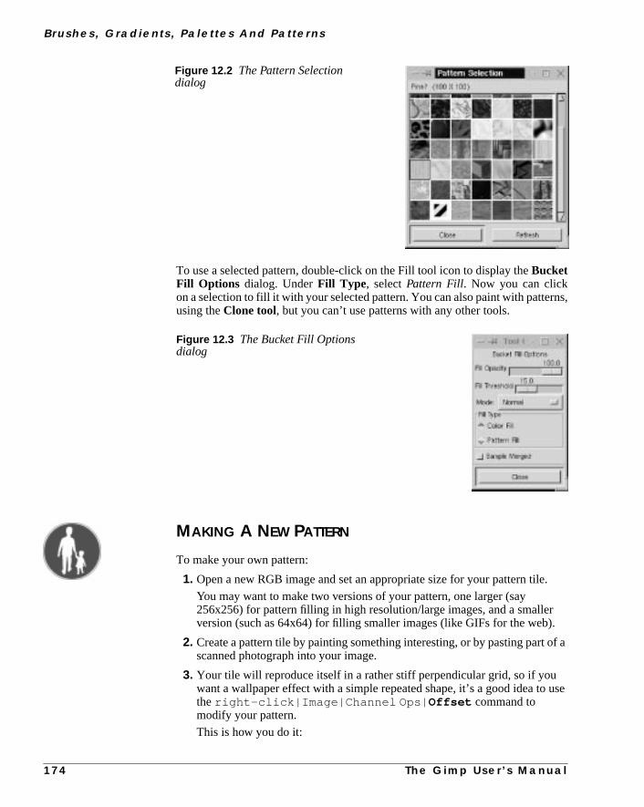
B r u s h e s , G r a d i e n t s , Pa l e t t e s A n d Pa t t e r n s
ns,
.
r.
f a
use
To use a selected pattern, double-click on the Fill tool icon to display theBucketFill Options dialog. UnderFill Type , selectPattern Fill. Now you can clickon a selection to fill it with your selected pattern. You can also paint with patterusing theClone tool, but you can’t use patterns with any other tools.
MAKING A NEW PATTERN
To make your own pattern:
1. Open a new RGB image and set an appropriate size for your pattern tile
You may want to make two versions of your pattern, one larger (say256x256) for pattern filling in high resolution/large images, and a smalleversion (such as 64x64) for filling smaller images (like GIFs for the web)
2. Create a pattern tile by painting something interesting, or by pasting part oscanned photograph into your image.
3. Your tile will reproduce itself in a rather stiff perpendicular grid, so if youwant a wallpaper effect with a simple repeated shape, it’s a good idea totheright-click|Image|Channel Ops| Offset command tomodify your pattern.
This is how you do it:
Figure 12.2 The Pattern Selectiondialog
Figure 12.3 The Bucket Fill Optionsdialog
1 7 4 T h e G i m p U s e r ’ s M a n u a l

C h a p t e r 1 2
viewt
ge
on
(for
• First, check out what your present pattern will look like by openingright-click|Filters|Map| Small Tiles . This filter is morethan useful when you create patterns, because it gives you a sneak preof what your pattern will look like, as well as the opportunity to modify i(read more about this filter in “Small Tiles” on page 558).
• Open theLayers & Channels dialog box andduplicate the patternlayer.
• Open theOffset dialog box and offset the top layer by x/2 and thebottom layer by y/2. (This is not the same as offsetting the original imawith the Offset by (x/2),(y/2) button!)
Set the top layer inMultiply Mode (if the background color is otherthan white, the pattern element must be created in a transparent layertop of the colored background layer), thenflatten the image and take alook at your pattern once again with theSmall Tilespreview.
4. If you have created a more complex pattern or have used a photographexample, a wood structure), you will also need to use theOffset option toremove visible seams between tiles. This is described in more detail in“Offset” on page 294. Theright-click|Filters|Map|Make Seamless filter is also a useful tool, but the result is often a bit
Figure 12.4 A single dot will not render a good pattern
Figure 12.5 If you use Offset you will get a better pattern, asyou can see in the final outcome (right)
T h e G i m p U s e r ’ s M a n u a l 1 7 5

B r u s h e s , G r a d i e n t s , Pa l e t t e s A n d Pa t t e r n s
this
in
e
d
lack)
lor
blurred (see “Make Seamless” on page 550 for more information about filter).
You can also take an existing pattern and change it. System patterns areusr/local/share/gimp/patterns (of course, this location varies,depending on site setup).
5. When you’re satisfied with the tile, resize the image to fit the tile size of thpattern you want to create. UseFile|Save As to save the image as a PATfile in the.gimp/patterns directory.
6. Click on right-click|Dialogs| Patterns to view thePatternSelection dialog. Press theRefresh button and your newly created patternwill be available for use.
PALETTES
Useright-click|Dialogs| Palette or File|Dialogs| Paletteto display theColor Palette dialog.
PALETTE OPTIONS
SelectNew Palettefrom theOps pull-down menu to create a new palette, anname the new palette. The same pull-down menu allows you torefreshanddeletepalettes. When you create a new palette, you always start with an empty (bpalette.
To add a color to the new palette, use theColor Picker tool to select a color froman image, or specify a color in theColor Selectiondialog (open this dialog bydouble-clicking in the foreground color swatch in the toolbox). The chosen cois always visible as theforeground color in the toolbox. PressNew to add thiscolor to your palette.
Figure 12.6 The Color Palette dialog
1 7 6 T h e G i m p U s e r ’ s M a n u a l

C h a p t e r 1 2
43).
l-
s-
ry, it
nly:
nd
se
log.
ors,
outs theedlors.
n-andnary
ng-
Edit a color in your palette by selecting it and pressing theEdit button, which willopen the Color Selection dialog (see “The Color Selection Dialog” on page 1You can delete a color by selecting it and pressingDelete.
As soon as you edit asystem palette(any palette other than your personal paettes), it will move to yourpersonal palette directory. You can’t delete a systempalette; Gimp will simply acknowledge that you don’t want to use it in this sesion. However, if you delete apersonal palette, it is gone forever.
Note that if you have added a large number of palettes to the palette directowill take some time before they are all displayed in the pull-down menu.
CREATING A PALETTE FROM AN INDEXED IMAGE
You can create a palette from an indexed image. This is quite handy if you owant to use the specific colors contained in the image. Here’s how you do it
1. Convert the image to Indexed mode withright-click|Image|Indexed .
2. In theIndex dialog, select how many colors your palette should comprise aclick OK.
3. Save the palette withright-click|Image| Save palette .
4. Name the palette and press OK.
Your palette now exists, but Gimp will need to re-read all the palettes. Uright-click|Dialogs| Palette to display theColor Palette dialog.Click on Refresh Palettesin the Ops pull-down menu, and your new palettewill become a choice in the list of available palettes on the Color Palette dia
HintsTip: Use palettes when you want to create images with a fixed number of colfor example, when you are creating icons.
If your screen depth is only 8 bit (256 colors), you’ll need to be concerned abwhether the created icons use up all 256 colors. If your icon manager reducenumber of colors it may look awful. You’ll need to create a palette with a limitnumber of basic colors for your icons and then create the icons using those co
The palette file format is similar to the format of the rgb.txt file used by the X Widow System. Each color has a line for the RGB number values of the colorthen the name of the color. This means that you can edit palette files in an orditext editor.
THE GRADIENT EDITOR
When we mention gradients, theBlend tool may come to mind. The Blend toollets you “flood” a selection or image, starting with one color and smoothly chaing into another.
T h e G i m p U s e r ’ s M a n u a l 1 7 7

B r u s h e s , G r a d i e n t s , Pa l e t t e s A n d Pa t t e r n s
tomery
ool
usewithf thed in
in
tsn,
t.
Gimp allows you to do even more complex blends with a tool called theGradi-ent Editor . The Gradient Editor comes with a number ofpresetcustom gra-dients, but you can also create your own gradients or edit one of the cusgradients with this tool. The Gradient Editor is a flexible tool that can create vadvanced gradients.
To apply a gradient from the Gradient Editor you double-click on the Blend ticon in the toolbox and selectCustom (from editor) from the Blend pull-down menu in the Blend Tool Option dialog.
The custom gradients from the Gradient Editor can be very useful. You canthem in advanced fountain fills or patterns, and you can also create objectsthem, like an eyeball, a hole or a pipe. For tips on how to make the best use ogradients in the Gradient Editor, read about the Blend tool, which is describe“The Blend Tool Or Gradient Fill” on page 131.
THE GRADIENT EDITOR DIALOG
ClickonFile|Dialogs| Gradient Editor orright-click|Dialogs|Gradient Editor to open the Gradient Editor. The user interface is shownFigure 12.8. You’ll find a list of all available gradients underGradients, and thecurrently selected gradient can be seen in a preview window.
The buttons to the right let you create, copy, delete, save and refresh gradien. Ifyou click the right mouse button in the gradient preview window and hold it dowa menu of editing tools will appear for that gradient. You can alsozoomthe gra-dient with thezoom buttons present in the main dialog.
The Save as POV-Raybutton allows you to save a gradient in POV formaPOV-Ray is a popular ray tracing software program.
If you have downloaded a gradient and placed it in.gimp/gradients , youwill have to press theRefresh gradients button to see and use it.
Figure 12.7 This example showshow a gradient was used to createpipes.
1 7 8 T h e G i m p U s e r ’ s M a n u a l

C h a p t e r 1 2
mp/ited
thissonal
lick,lick
ent
rns a
dor
Edited system gradients will be saved to your personal gradient directory (.gigradients) . So if you want to use the original system gradient, and not the edcopy, just delete or move the edited copy from your personal directory.
If you delete a system gradient, it just means that you don’t want to use it insession. However, as is the case with personal palettes, if you delete a pergradient it will be gone forever..
So, What Can You Do With The Gradient Editor?Start by copying a gradient and playing around with it. Select a gradient and con the Copy gradient button. This will bring up the Copy Gradient dialogwhich will ask you to name the new gradient. Name the copied gradient and cOK. If you edit a system gradient, it will now be copied to your personal gradidirectory, as when you edit system brushes or palettes.
Note: There is no undo option in the Gradient Editor.
THE GRADIENT PREVIEW WINDOW
The trianglesat the bottom of the gradient preview window arecolor sectionmarkings. Two kinds of marks exist: blackendpointsand whitemidpoints. Thearea between two black points is called asegment. In the gradient shown in Figure12.8 a segment has been selected by clicking on it. A selected segment tudarker shade of gray.
Adjusting Endpoints And Midpoints
• You canmove an entire selection by clicking in the darker gray field andragging, but you can only move it as far as the next midpoint to the leftright.
Figure 12.8 The Gradient Editor dialog
T h e G i m p U s e r ’ s M a n u a l 1 7 9

B r u s h e s , G r a d i e n t s , Pa l e t t e s A n d Pa t t e r n s
than
iew
• If you move awhite midpoint (by clicking and dragging on it), you willsee thecolor transition shift as the balance between the two endcolors is being changed.
• Dragging ablack endpoint (not the ones to the extreme left or right,because you can’t move them) willstretch the area between thatendpoint and the midpoint, making itwider or narrower. The stretchlimit is the next midpoint to the left or right.
• If you click on anendpoint, then press Shift and drag, you willcompress or expand the entire selection in the drag direction. Thisdeformation will also include the neighboring midpoint, which will movealong until you reach the next endpoint.
• You canextend or add to a selection by pressing the Shift key andclicking on another segment.
Any of the described manipulations can be used on extended selections (moreone segment).
THE POPUP MENU
As mentioned before, if you press the right mouse button in the gradient prevwindow, a menu will appear for editing the colors in the selected segment.
Editing An Endpoint’s ColorYou can edit the color of the endpoints by selecting eitherLeft endpoint’scolor or Right endpoint’s color from the popup menu. This will bring up acolor select dialog where you can select a new color.
The Load from andSave tomenu options allow you toload a color from anRGBA channel to anendpoint, or tosavean existing endpoint color to one of thepreset RGBA channel swatches, so that you can load that color later.
Figure 12.9 The popupmenu
1 8 0 T h e G i m p U s e r ’ s M a n u a l

C h a p t e r 1 2
ns-r
at
”he
r
nt
TheLoad from command allows you to load some nice basic colors and traparent backgrounds. TheSave tooption is useful if you want to use a particulaendpoint color in another part of the gradient.
Blending FunctionsIn the Blending function for segment submenu, you will find some func-tions that control how the appearance of the gradient in your selection:
• Linear: This is the default function, and it causes the color to change a constant rate from one endpoint to another.
• Curved: Causes the end sections’ colors to change at a different “ratethan the colors in the middle section. Think of it as a semi-circle where tcolor changes more at the ends and less in the middle.
• Sinusoidal: This is the opposite ofCurved, so the rate of change is slowat the ends and fast in the middle.
• Spherical increasing: Causes the color change rate to be faster on theleft and slower on the right.
• Spherical decreasing: The opposite of spherical increasing; the colorchange rate is slower on the left side and faster on the right side.
ColoringThe coloring type for segment submenu lets you choose a color model foyour selection or segment. You can choosePlain RGB and two kinds ofHSV.See “Color Models” starting on page 187 for more information on the differecolor models.
Figure 12.10 The endpoint’sLoad from menu
T h e G i m p U s e r ’ s M a n u a l 1 8 1

B r u s h e s , G r a d i e n t s , Pa l e t t e s A n d Pa t t e r n s
tedill be
ents
ntslectr ofes
to
nd
of
y)nt
SegmentsTheSegmentcommands will work on the selected segment. If you have selecmore than one segment, they will not be treated as a unit. Each segment wtreated separately:
• Split segment at midpoint: Puts an endpoint at the midpoint andthen divides the two new segments with new midpoints.
• Split segment uniformly: Lets you specify how many splits youwant to make in the selected area.
• Delete segment:Deletes the entire selection, not just the segment youpress the right mouse button in.
• Re-center segment’s midpoint: Re-centers the midpoints in all ofthe selected segments.
• Re-distribute handles in segment: Evenly distributes all thepoints in the segment. This is useful if you have selected several segmand want a smooth gradient in the selection.
Selection OperationsThe Selection operationssubmenu allows you toflip or replicate the segmentand also allows you toblend the endpoints’ colors and/or opacity:
• Flip segment: Lets you flip or reverse a segment or selection. Flip canbe used to change the order of two segments. First, select two segmeand flip both together. Deselect one segment and flip the other one. Sethe first segment and flip that one, too. Now you have changed the ordeyour segments. This can be done to more than two segments, and givyou the freedom to change the structure of the gradients.
• Replicate: Provides a small dialog in which you can copy the selectedsegment(s) as many times as you like. The copies will be squeezed inthe original segment’s space.
• Blend endpoints’ colors: Only works if you have selected more thanone segment. It will blend the color in the endpoints of the selection, awill subsequently “merge” your segments so they blend gradually fromthe selection’s left handle to the right handle, thus changing the color the endpoints inside the selection.
• Blend endpoints’ opacity: Works the same way as blending colors.This command will create a soft transition from the opacity (transparencin the left endpoint to the opacity in the right endpoint of a multi-segmeselection.
1 8 2 T h e G i m p U s e r ’ s M a n u a l


P A R T
IV Pre-press Knowledge• COLOR MODELS
• PRE-PRESS
• SCANNING

C H A P T E R
13 Color ModelsIf you want to work seriously with digital imagingand/or pre-press, you need to understand color —how it works in real life and how it works in yourcomputer.

C o l o r M o d e l s
dis-S.
is
at theersec-ree
ors.f the
qual
et ofolorr is
eaklt in
cursthisway.
Color models are used to classify and standardize color. In this chapter we’llcuss a few of the more popular models: RGB, CMYK, indexed, HSV and NC
RGBRGB stands for the three colors used in the RGB system:red, greenandblue. Per-haps an “L ” for “ light” should be included as well, because this color modelvery much based on light.
Imagine three spotlights (a red one, a green one and a blue one), directedsame spot on a white screen. Because each spotlight adds more light, the inttion of two spots will be brighter than just one. The brightest spot is where all thspots intersect; that intersection is white.
As you may know, the RGB model is used by televisions and computer monitThe colored spots on a TV screen are red, green or blue, and the interaction ocolors determines what the eye perceives. If the color spots shine with estrength, the visual impression is of white or gray.
RGB is called anadditive color model, because light isaddedto light, whichresults in brighter colors. In the RGB model, every color is represented as a sthree values: a value for red, a value for green and a value for blue. Each cvalue can range from 0 to 255. If all three color values are 0, the resulting coloblack; if all three colors are 255, the color is white.
If you think of this model as spotlights, then it’s easy to understand that wlights (low values) mean darker colors, while strong lights (high values) resubrighter colors.
RGB can represent more than 16 million colors (which is often calledTrue-Color). The calculation is simple:
256 red values x 256 green values x 256 blue values = 16,777,216 colors
However, RGB can produce only 256 shades of gray, because gray only ocwhen all three color values are equal. If your computer only has 8 bit color,doesn’t matter, because you’ll never be able to see more than 256 colors any
Figure 13.1 The RGB colormodel
1 8 8 T h e G i m p U s e r ’ s M a n u a l

C h a p t e r 1 3
4 —lionnip-rsionitels
e ahese
andp, a
tsare
ch
olor
The reason why there are 256 RGB color values — and not, for example, 102is that Gimp was programmed for 8 bit color channels. In most cases, 16 milcolors is quite satisfactory, but there are certain highly specialized image maulation programs that can handle 16 bit color channels. There is also a new veof Gimp under development called GIMP HOLLYWOOD that will include 16 bcolor channels. In this book, we will focus on 8 bit (256 value) color channsince that is what you’ll work with in Gimp.
CMYKCMYK is another important color model. CMYK stands forcyan, magenta,yellow and black (K for key color). These colors are sometimes calledpro-cesscolors, because they are used in four-color process printing. If you havcolor printer, you may have noticed that the toner in the machine consists of tprimary colors.
All other colors can be created by mixing these primary colors. Cyan, magentayellow are theoretically all you need, but to make a print look sharp and crisblack plate is also used in the printing press.
CMYK is called asubtractive color model, because the process ink pigmen“subtract” light when mixed, or absorb certain colors and reflect others (whichseen by your eyes).
INDEXED
Indexed or mapped color works with a fixed color value for each pixel. Eacolor used in a given image is put in acolor table or color map, which is partof an indexed image file. This color table is then used to map the appropriate cto each pixel to be displayed.
Figure 13.2 The CMYK color model
T h e G i m p U s e r ’ s M a n u a l 1 8 9

C o l o r M o d e l s
tore.om-lim-benot
n no
IF.dis-
agesexed
Indexed image files contain less data and therefore require less memory to sIf you are designing graphics for the web, you should keep in mind that many cputers can’t display 24 bit color. Many people out there use monitors that areited to 256 colors. Therefore, your beautiful, “millions of colors” image mayindexed to a measly 256 colors when it is reproduced on their monitor. It maylook very good, and it will take the same amount of time to download.
GIF format images, which are often used on the web, are indexed to contaimore than 256 colors.
Two kinds of image file formats are commonly used on the web: JPEG and GBoth formats have advantages and disadvantages, but we won’t get into a bigcussion about GIF vs. JPEG here.
The important point to remember is that GIF images are indexed and JPEG imaren’t. Among the many reasons to use GIFs, the most important is that indimages are small files.
Figure 13.3 An RGB image
Figure 13.4 An Indexed
1 9 0 T h e G i m p U s e r ’ s M a n u a l

C h a p t e r 1 3
wn-sub-ular
ep—a-any
on
u
of
andt 0lue,
Also note that if you assign aweb-indexed paletteto a GIF image, you canbe sure that “what you see is what you get.” In other words, everyone who doloads the image will see almost exactly the same colors, without any strangestitutions. Those images will always look almost exactly the same in a particbrowser, whether displayed with 8 bit, 16 bit or 24 bit output.
Don’t index your image before you’re finished with it. And always save and kean RGB copy of your original before converting the image to indexed coloryou’ll need the original for any future image editing. Most of the image informtion is lost forever as soon as you convert it to indexed format, and you regainof the information by converting back to RGB. Also note that you can’t workan indexed image with most filters.
HSVHSV stands forHue, Saturation andValue. The HSV color model is used inmost options in the Image dialog for Colors (right-click|Image| Colors )and Channel Ops (right-click|Image| Channel Ops ). It is also used incertain filters and color modes.
This color model is best understood if you open theColor Selection dialog(click on the foreground/background icon at the bottom of the toolbox) andlook at the three top sliders markedH, S andV. Drag these three sliders as yoread this passage, and notice how the color is affected. TheR, G andB sliders dis-play the equivalent values for the RGB color model. Let’s take a look at eachthese three parts of the HSV color model, starting with H for Hue.
HUE
Hue describes where a color lies along thespectrum, or what “rainbow color”it is: for example, red, orange, indigo or green. As in a rainbow, the startingending color is red. Hue values are organized into a color circle, with red adegrees, yellow at 60 degrees clockwise, continuing with green, cyan, bmagenta and red again at 360 degrees.
Figure 13.5 TheColor Selection dialog
T h e G i m p U s e r ’ s M a n u a l 1 9 1

C o l o r M o d e l s
ll
luesim-
c-our
SATURATION
Saturation is how pure or “loud” the color is. The saturation value goes from0 (grayscale) to 100 (maximum purity). A low value will provide a neutral, ducolor, and a high value means a strong, pure color.
VALUE
Value is another way of sayingbrightness. A value of 0 means completelyblack, while 100 is the brightest value that a color can have. Maximum vadoesn’t mean white, however (unless saturation is zero). Maximum value isply the brightest value a color can have at a particular saturation.
NCSNCS(theNatural Color System) is the system used by architects and interior deorators. This is also often the system that’s used when you buy paint for yhouse (unless you live in the U.S., where you might see theMunsell systeminstead). The NCS color model is based on the sixelementary colors: yellow,red, blue, green, black and white.
Figure 13.6 The HUE color circle
Figure 13.7 The NCS circle
1 9 2 T h e G i m p U s e r ’ s M a n u a l
C h a p t e r 1 3
lors.
lor
eirlow,
the
c-tellslike
irstage
e.rownally,
eryout
reced
100-om-f an
it,and
hereinghose
esssil-
spoted by
Spot
All colors can be described by how closely they resemble the elementary coThe elementary colors and the color scale between them form athree-dimensionalspindle-shaped body (like two cones put together). From the cobody, acolor circle andcolor triangles can be derived. In the color circle (ahorizontal “slice” of the color body), the colors are arranged according to thposition in the spectrum, evenly distributed between the four basic colors; yelred, blue and green.
For every color in the circle, a vertical section, shaped like a triangle, showsdifferent shades of a color:whiteness, blackness and colorfulness (satura-tion).
Colors are then identified according to the following scheme:Y70Rs70c20.
Y stands for yellow and70Rmeans 70% red. This indicates a position in the spetrum circle somewhere between the elementary colors yellow and red. It alsous that this orange color is composed of 30% yellow and 70% red, i.e., a bita blood orange. Likewise,R70B would indicate a bluish violet color, andG70Ya lemon yellow. Note that the first letter in the color code always refers to the fprimary color (clockwise) in the color segment, and that the color percentalways refers to the second primary color.
With the notations70, we have turned from the color circle to the color trianglIt means that our orange color has 70% blackness, which gives us a dark bcolor (whereas a blackness value of 10 would produce shades of peach). Finwe havec20, which means that our color has 20% colorfulness, which is not vintense. SoY70Rs70c20indicates a color best described as a dark, washed-maroon.
You can get a fair idea of what this color looks like by opening theColor Selec-tion dialog and adjusting theHSV slidebars. In HSV space, red is at 0 and puyellow is at 60 degrees. Consequently 70% red and 30% yellow would be plaat 18 degrees in the Hue field. Set the Saturation field to 20, and Value to 30 (70=30). Note that the match isn’t perfect because the color systems aren’t cpatible. This is only an approximation, and you can’t use this method instead oNCS color chart. (The largest difference is cause by Hue.)
Even if you don’t use NCS on your computer, you should still understandbecause it is the most widely used color system for professional designersarchitects in many European countries. If you get an assignment in Europe wa client wants you to suggest different colors for a pattern, an object or a build(using a program like Gimp or Photoshop) you should be prepared to discuss tcolors in terms of NCS values, and not RGB or HSV.
SPOT COLOR
Spot colors or custom colors are colors defined in a commercial customcolor system and are normally used for printing in color when four-color procprinting won’t do. For example, you may want to use a non-rasterized smoothver gray for text on a poster; in that case, you’d have to specify a predefinedcolor. Pantone and Truematch are the most common custom color systems usprofessional printers. Read more about spot colors in “Using Channels ForColor Separation” on page 355.
T h e G i m p U s e r ’ s M a n u a l 1 9 3
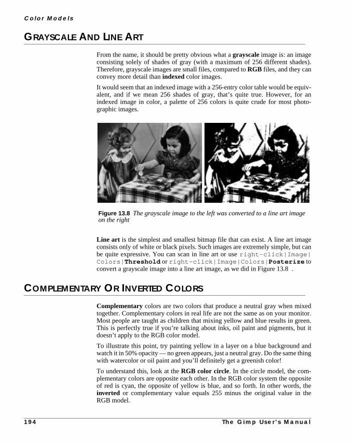
C o l o r M o d e l s
es).
uiv-r anto-
gecan
editor.en.it
ndhing
ositethethe
e
GRAYSCALE AND LINE ART
From the name, it should be pretty obvious what agrayscaleimage is: an imageconsisting solely of shades of gray (with a maximum of 256 different shadTherefore, grayscale images are small files, compared toRGB files, and they canconvey more detail thanindexed color images.
It would seem that an indexed image with a 256-entry color table would be eqalent, and if we mean 256 shades of gray, that’s quite true. However, foindexed image in color, a palette of 256 colors is quite crude for most phographic images.
Line art is the simplest and smallest bitmap file that can exist. A line art imaconsists only of white or black pixels. Such images are extremely simple, butbe quite expressive. You can scan in line art or useright-click|Image|Colors| Threshold or right-click|Image|Colors| Posterize toconvert a grayscale image into a line art image, as we did in Figure 13.8 .
COMPLEMENTARY OR INVERTED COLORS
Complementary colors are two colors that produce a neutral gray when mixtogether. Complementary colors in real life are not the same as on your monMost people are taught as children that mixing yellow and blue results in greThis is perfectly true if you’re talking about inks, oil paint and pigments, butdoesn’t apply to the RGB color model.
To illustrate this point, try painting yellow in a layer on a blue background awatch it in 50% opacity — no green appears, just a neutral gray. Do the same twith watercolor or oil paint and you’ll definitely get a greenish color!
To understand this, look at theRGB color circle. In the circle model, the com-plementary colors are opposite each other. In the RGB color system the oppof red is cyan, the opposite of yellow is blue, and so forth. In other words,inverted or complementary value equals 255 minus the original value inRGB model.
Figure 13.8 The grayscale image to the left was converted to a line art imagon the right
1 9 4 T h e G i m p U s e r ’ s M a n u a l

C h a p t e r 1 3
om-of
rongldtheom-
However, this doesn’t work with pigments in real paint. In thenatural colorcircle, which you’d need to use for real paint pigments, you can see that the cplementary color of yellow isn’t blue but violet, and the complementary colorblue is orange.
Watercolor artists often add a complementary color to neutralize an overstbackground without dulling it. A real life example: Why do you think some oladies have “blue” hair? They (or their hairstylists) are trying to neutralizeunwanted red/yellow shades in their gray hair by using a dye containing the cplementary color, blue or violet.
Figure 13.9 RGB model on left and natural color model on right
T h e G i m p U s e r ’ s M a n u a l 1 9 5
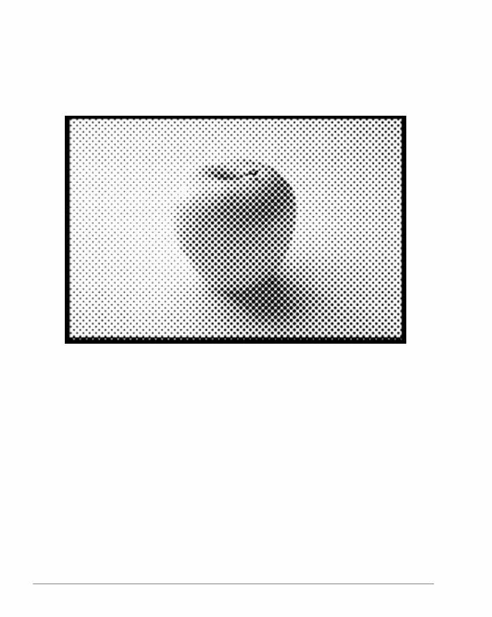
C H A P T E R
14 Pre-press And Color In GimpThis chapter will help you prepare your Gimp imagesfor the printing press. You will also learn some simplecolor calibration techniques for your monitor.

P r e - p r e s s A n d C o l o r I n G i m p
ritallogo.such
rpress.
ners,ttenro-ulduserpro-
of
and
theare
oreurfer
illmost
ltfew
d-of-thehis
WHAT IS PRE-PRESS?When people think aboutpre-press, they are usually thinking about taking theiimage or book to the local printer so it can go to press. For a long time, the digpre-press business has been dominated by a company with an apple in theirPrograms for pre-press have also traditionally been provided by companiesas Adobe, Corel and Macromedia, and tight bonds often exist betweengraphicssoftware and printing hardware . This system means that it is very easy fothe average Macintosh user to create digital designs and send them to pre-
Since the market has been dominated by Apple for so long, most of the scanprinters and monitors come with drivers and calibration tools adjusted and wrifor Macintosh. The only thing the graphic designer has to do is get a printing pfile from the print house, put it in the program, and everything is set as it shobe. People can argue about whether this is the right way to go, or whether theshould have more control over settings or parameters, but using preset Macfiles is certainly very handy.
When you meet with pre-press people for the first time, you’ll hear a lotbuzzwords (lpi, dpi, ppi, Pantone colors, etc.). You’ll also have to solve the prob-lem of how to format your Gimp images for Mac users and Mac print shops,figure out how to transfer large image files.
In this chapter, we will try to answer these questions and sort out some ofbuzzwords. And relax, you really don’t need a Mac or a Windows box to prepfor pre-press. All you need is Gimp and UNIX.
PRINTING FROM GIMP
Gimp is not as intuitive as Photoshop is about pre-press issues. Gimp is mfocused on web design. In Gimp, you always see the image size as the web swould see it.
Why? By default, images with no resolution information provided in the file wbe opened at 72 ppi (pixels per inch). This is the case for Netscape, and forother programs. Gimp doesn’t provide any dialogs for incorporatingprintingvaluesbefore you start creating your design. Don’t worry; it isn’t very difficuif you just plan ahead a little. You simply have to use your good sense and acalculations.
If you want to adjust or calibrate your scanner, monitor, etc., you’ll need todo it by hand. If you don’t calibrate, it’s very likely that you will be disappointewhen you see the printed outcome of your work. Even if you don’t have a topthe-line calibration kit, the printout will probably be closer to what you see onscreen than before the calibration. We’ll cover calibration in detail later in tchapter, but let’s begin with a discussion of file types.
1 9 8 T h e G i m p U s e r ’ s M a n u a l

C h a p t e r 1 4
t
then. Iffile
out-our
ause
inguse.s soeer isentthe
size
, but
usethatatave
setrintppdtter.
FILE FORMATS FOR PRINTING
Many image file formats exist, but most professional printers use only two:EPS(Encapsulated PostScript) andTIFF (tagged image file format). Some prinshops can also manage JPEG and compressed EPS.
If you don’t want to save your image into one of these formats, you can importimage file into alayout program. Most print shops that accept PC files casupport programs like Adobe FrameMaker, Adobe Illustrator and Corel Drawyou import your image to a such a program and save it in the program’s nativeformat, the print shop will be able to print from that file instead.
PostScript FilesIf your local print shop can manageEPS files, you should probably use that for-mat. EPS is device and platform independent, and you can be sure that thecome will look just like the image you created (assuming that you calibrated ymonitor and that you’re printing to aPostScript printer).
If you use EPS, make sure that your print shop can handlecolor adjustmentin an EPS file, and that they are able topreview it. If they can’t, you’ll need tobe sure that all settings and colors in your file are perfect from the start, becthe printer won’t be able to fix it for you afterwards.
If you have a large print job, you also need to know whether they canrearrangethe pages in the PostScript file. If they can’t, you may have to pay for two printplates instead of just one. This has to do with the type of binding you want toIn a DTP program there are automatic functions that will rearrange the pagethat they will fit your choice of binding. For example, in a “saddle” binding, thfirst and last pages will be printed on the same large piece of paper (this papthen folded like a roof or saddle). Only the pages in the middle of the documwill actually be placed on the printing plate in the order that you see them inoriginal text file.
Gimp includes a powerful PostScript file saver in which you can specify paperand resolution as well as the type of PostScript.
To create an EPS file, check theEncapsulated PostScriptcheckbox on theSave PostScript dialog box (right-click|File| Save As and thenchoosePostScript from the Determine file type pull-down menu). Mostprint shops can take plain PostScript files, so this may also be a option for youyou still have to specify all parameters as you do when you save a PS file.
You can also use theright-click|File| Print command andprint tofile. You can adjust the PostScript file so that the options that the print hoprinter or image setter understand are included in the PostScript file. You doby asking whatppd (printer parameters description) file you should use for thprinter, or even better, ask to get the ppd file from the print house. When you hthe ppd file, enter the setup dialog from the printer dialog window. Here you’llthe printer to Postscript Level 1 or 2 depending on what kind of printer the phouse is going to use. The next step is to specify which ppd file to use in thefield; simply press theBrowsebutton and “open” your ppd file. The PostScripfile generated will now support the options available for the print house prin
T h e G i m p U s e r ’ s M a n u a l 1 9 9

P r e - p r e s s A n d C o l o r I n G i m p
rint
geatsingter.PS
ourse
oto-imp
xelss isoni-.
nch100wney
otfig-0
qua-
size
heize so
ingn’t
The file output will be PostScript and not EPS. You also have to talk to your phouse to see if they can take plain PostScript files instead of EPS files.
TIFF FilesIf your printer doesn’t support EPS or PostScript, you’ll have to save your imain an ordinary image format like TIFF or JPEG. Be aware that some image form(for example, TIFF) differ in PC and Mac environments. The advantage of usTIFF is that you can make a high-quality proof even on a non-PostScript prinAlso, TIFF is a good choice if your image’s background is white, because Esometimes has a tendency to produce a weak tint in large white areas.
If you ship your images as ordinary image files, you must remember to tell yprinter in whatsizeyou want the images to be printed. This is important, becauprinters normally expect plain image files to be created in Photoshop. In Phshop, the image size and resolution is included in the image file. However, Gonly supports (so far) one resolution (72 ppi or monitor resolution).
RESOLUTION AND IMAGE SIZE
As we have stated before, Gimp images only have one resolution: 72 ppi (piper inch), which is the unspecified default screen resolution. Obviously, thiideal for web publishing, because web surfers are viewing images on their mtors. However, 72 ppi resolution is far too low for any kind of serious printing
For example, suppose that your printer tells you that to make your 50x60-iposter look good, you need a minimum resolution of 100 ppi. To provide theppi resolution, you’ll need to create a larger image in Gimp and then scale it dowhen you save it as a PostScript or EPS file (or the printer will do it when thimport the image into one of their programs).
In theFile|New dialog, you always specify the image size in pixels, so it’s nvery difficult to calculate the size you need for a certain resolution. Using theures in this example, we’ll just multiply the image width and height (50x6inches) by 100 (the resolution) and insert those values asWidth andHeight intheNew Image dialog box.
50 x 100 equals 5000 pixels and 60 x 100 equals 6000 pixels. The standard etion is simple:
Note: Gimp image size = desired ppi desired height or width in inches
As a rule of thumb, always adjust the image sizebeforeyou start making theimage. Ask your printer for the required resolution, and calculate the imageyou need to produce a nice printed output.
If you need a high resolution for your print job, your images will be huge on tscreen. The good news is that Gimp is smart enough to adjust the canvas sit will never be bigger than your display.
So, how can you fix it if you didn’t do the necessary calculations before creatthe image, or if the printer tells you that your image resolution is too low? Dopanic, there is a way out of this dilemma. You canscale the image a certainamount, because Gimp caninterpolate the image.
2 0 0 T h e G i m p U s e r ’ s M a n u a l

C h a p t e r 1 4
aresrme-geheer)
ismple,rint
but
taincloseOn
hen
dpinal
n,
ller)
r caninterlot
terr theput
Interpolation means that when you enlarge an image by scaling it, Gimp compneighboring pixels, makes an assessment of their color and calculates an intediate color for the new pixels. This works well if you only have to resize the imaa small amount, but don’t try it for scaling the image to double its size or more. Timage will end up looking blurred and fuzzy at the edges. For better (but slowinterpolation, check theCubic interpolation checkbox on theDisplay tab inthePreferences dialog (File|Preferences ).
PREPARING FOR THE PRESS
DPI, LPI, PPI AND SCANNING RESOLUTION
If you’ve never done a high-end print job before, the first thing you should domake some phone calls to local print shops and ask a few questions. For exaif you want to print a 22x34-inch poster, you’ll need to make sure that the pshop can print that size and in the resolution you want.
People often think that a higher resolution is automatically a better choice,that’s not always true. For a poster, you need to consider theviewing distance.Fora large image, like a commercial poster, the beholder will observe it from a cerdistance and will never see the coarse halftone dots unless he or she gets veryto it. For that reason, you don’t have to print a poster in a very high resolution.the other hand, if you’re making a cover for a monthly fashion magazine, tyou’ll need a very high resolution, indeed.
Lpi And DpiYou have probably often heard the expressiondpi (dots per inch) in reference tohome or office printer resolution (for example, a 600 dpi laser printer or a 300inkjet printer). However, the term “dpi” is not as commonly used in professioprinting.
Lpi is the most widely used term in professional printing for printer resolutioand one you’ll encounter as soon as you enter the print shop. Lpi stands forlinesper inch, and is used forscreening, the finehalftone pattern you see when youlook closely at a picture in a newspaper. The higher the lpi, the more (and smahalftone dots are squeezed in per inch.
Each halftone dot is made up of very small “dpi dots.”Dpi can simply bedescribed as the maximum number of these microscopic dots that the printemanage to print per inch. Inexperienced users tend to think that 600 dpi in a pris equivalent to 600 ppi in an image file, but they are not equivalent. It takes aof dpi to represent a ppi.
For more information about the relationship between dpi and lpi, see “PrinTable” and “Image Table” on page 217. These tables can serve as a guide folpi needed to produce different types of printed material and/or which outdevice can produce an lpi suitable for your needs.
T h e G i m p U s e r ’ s M a n u a l 2 0 1

P r e - p r e s s A n d C o l o r I n G i m p
an
h.
se it
ake40
res-we
x0 dpi
ertainsoft-pi.te aNE,
opti-
00pi,”
ops,0.
ionanon
Ppi And Scan ResolutionAfter you’ve chosen an appropriate lpi (lines per inch) for your print job, you ccalculate theppi (pixels per inch) resolution you’ll need in your digital image. Inthe following example, we will make a 15"x15" poster out of a 4"x4" photograp
First a general rule of thumb:image ppi = 1.6xlpi(assuming that the image fileand the printed output have a 1:1 ratio). This equation is not exact, becaudepends on what kind of quality you want (see “Lpi Table” on page 216).
We chose an lpi of 150, which is good enough for a poster. If we wanted to ma life-size print of the 4"x4" photo (1:1 ratio), we would scan the image in at 2dpi (1.6x150).Note that scan dpi is the same as ppi.
To make a large print from a small scanned image, we’ll need a much higherolution. We want to produce a 15"x15" printed poster from a 4"x4" photo, sowill need to scan the photo in at a higher resolution than the 240 ppi.
The calculation to use is:scan resolution = desired ppi x (wanted size/actual size).
If we insert the figures from our example into this algorithm, we’ll get: 240(15/4), which equals 900. This means that you need to scan the photo in at 90to be able to print the 15"x15" poster at 150 lpi.
Note that when we’re talking about scan resolution, we mean theoptical scan res-olution.When you read a sales brochure about scanners, and it says that a cscanner can scan at a resolution of 9,000 dpi, this figure usually refers to thewareinterpolated resolution. The real scan resolution may be as low as 300 dAlways make sure that you scan in optical resolution. If you want to interpolascanned photo, Gimp will do a much better job than the scanner software (SAwhich is the scanner program we recommend to use with Gimp, only scans incal resolution).
Scan dpiis not the same as printer dpi, so don’t think that you have to scan at 6dpi to print to a 600 dpi laser printer! Scan resolution is measured in “scan dwhich is equivalent to ppi (pixels per inch).
After having made these calculations, we can start calling the local print shasking if they can print a poster that is 15"x15" large, using an lpi around 15
If you need to know more about lpi, dpi, ppi and screening, in-depth informatis provided later in “Resolution” on page 212. If you have a inkjet printer you calso read about that kind of printing in “Scanning, The Web And Printing”page 259.
2 0 2 T h e G i m p U s e r ’ s M a n u a l

C h a p t e r 1 4
toict
ingout-orsringan
n’tget-
n,youlled
lorsou
spotfile
on
blefrom
onnefor-
AT THE PRINT SHOP
WHY THE COLORS THAT LOOKED SO GOOD ON YOUR
MONITOR DON’T MATCH THE COLOR OF THE OUTPUT
Never give your image file to the printer and simply ask them to print it.If you do,you can more or less rely on the colors being screwed up.Color calibrationof your computer environment is one of the stumbling blocks when it comesimage production. If your monitor is not calibrated correctly, you can’t predwhat colors will actually be printed.
The most simple solution to this problem is to make a smallproof at home on acolor inkjet printer. If the proof’s color is correct as far as you’re concerned, brthis example to the printer and ask them to adjust the color so that the printedcome will match your proof. We will describe how to calibrate scanners, monitand the like later in this chapter, but remember that it’s always a good idea to ba proof or dummy to the printer as a reference. If you bring a proof, you cdemand a reprint if the colors of the printed product are incorrect.
Spot ColorIf you can only afford one or two color plates, or if a part of your design doeslook good in halftone pattern, there is another way of handling the problem ofting the right color. You can usespot colors from a commercial color systemlike Pantoneor Truematch. Instead of using the four-color process inks cyamagenta, yellow and black on the printing plates, you can choose any colorlike from a custom color chart, and apply that ink to a plate. Such inks are caspot colors.
Gimp doesn’t natively support spot colors, so if you want to use custom cowith Gimp you’ll have to buy a custom color map. Decide which spot color ywant to use, and give agrayscale file and a spot color specification toyour printer. If you want to use more than one spot color and you don’t have acolor separation program, you must give the printer an appropriate grayscalefor each color plate. Read more about spot colors in “Color Models” startingpage 187 and “Channels And Duotones” starting on page 351.
HOW TO TRANSFER IMAGES TO THE PRINT SHOP
Removable DrivesA common method of transporting images to a printer is by using removadrives, such as SyQuest and Ezdrive by SyQuest and Jaz and Zip drivesIomega.
The Iomega Zip drive, which can store 100 MB of data, is the most commremovable drive in the PC world. To decide what drive you should buy, phoyour local printers and ask what kinds of drives they support. Based on that inmation, decide what kinds of drive you should buy.
T h e G i m p U s e r ’ s M a n u a l 2 0 3
P r e - p r e s s A n d C o l o r I n G i m p
driverivesinters
as ato
S-entac-
or
-Ralsad the
eryCDhoto
er-filed
toing
this
ryven
ob-ailen
sent
Based on our own experience, we suggest a SCSI Zip drive because the Zipis fast and the old SyQuest drives are expensive and on their way out. New dfrom SyQuest have not been as successful as Iomega drives, and most prthese days support Zip drives.
CD-ROMCD-Recordable (CD-R) prices have also fallen, so CD-Rs can be considereddelivery medium for images. If you want to use CD-Rs, the best strategy isrecord in ISO9660 format without any extensions, which allows only 8.3 (MDOS format) file names. When you’re working on a project, it is more convenito have it on your hard drive. When you’re done, transfer it to the CD. This prtice will make it easier to keep a large number of images without having onemore very large hard disks.
CD-R quality is not as high as an ordinary CD. In the archive world, the CDmedium is not trusted. Most archives re-record CD-Rs at regular interv(because of concern about the medium and also because the machines that remedium are not likely to be around forever).
According to the National Swedish Archives, CD-Rs should be re-recorded evfive years (in contrast, they estimate that ink lasts 1,000 years!). An ordinaryhas a guaranteed lifetime of 20 years, so remember to re-record your stock plibrary at regular intervals.
Internet And BBSMany print shops have some sort of Internet connection or a Bulletin Board Svice (BBS). If they have an Internet connection, they can probably supportupload using theFTP protocol. If they do, all you need is an FTP program antheir address so you can upload files to their server.
If they have a BBS, then you need amodem and a terminal program thatsupports their BBS. You’ll need to ask them what kind of program you needuse. Several modem/terminal programs are available for UNIX/Linux includKermit andSeyon.
Tip: Although this doesn't apply to U.S. phone lines, it can be expensive to usekind of file transfer in Europe, where local calls aren't free.
We don’t suggest uploading files over 20 MB if you only have an ordinamodem. Some printers also charge you for each MB you upload, adding emore expense.
EmailWe don’t recommend that you email the file to the printer, because you’re prably starting with a fairly large image file, and the coding of the file as an emattachment makes it even larger. Therefore, the “upload” time will last evlonger. Also, it is not uncommon for files to become damaged when they areas email.
2 0 4 T h e G i m p U s e r ’ s M a n u a l

C h a p t e r 1 4
-e
fer
ofthee
derfiler the
itcu-ore
bestso actunnerac
rms(forSanepter
not
inux
et-at
FILE SYSTEM FORMAT
What kind of file system format should you use? Nearly all print shops supportFAT (File Allocation Table, an MS-DOS file system format) even if they usa Mac. If they don’t support FAT, you’ll have to use the Internet or BBS to transfiles.
Why FAT? Most UNIX system supports FAT, and Linux can even run on topa FAT file system. Support for the native Mac file system (HSPF) is rare inUNIX world. And don’t think that your local print house will support any nativUNIX or Linux file system, so we suggest that you stick to FAT.
If your print house doesn’t support FAT, we think you should seriously consifinding another printer who does. If they support FAT, you can create a FATsystem on your removable drive (Zip and Jaz PC disks come preformatted foFAT file system).
If you are running aLinux system, nice freeware (OSS) tools exist that makeeasy to manage Zip and Jaz drives using a GUI interface. Helpful how-to doments also exist for using both Iomega and SyQuest drives with Linux. For minformation, see http://metalab.unc.edu/LDP/HOWTO/HOWTO-INDEX-3.html .
SCANNING USING A UNIX OR LINUX SYSTEM
FREE SCANNER PROGRAMS
Because we are working with Gimp, Sane (Scanner Access Now Easy) is thescanner interface to use. Sane will run as a stand-alone program, but it can alas anextensionto Gimp. If you’re running Sane as an extension to Gimp, yocan open Sane from Gimp and scan straight into Gimp. Using Sane in this mais like having aTwain interface under Photoshop or a similar program in a Mor Windows environment.
Sane supports a wide range of scanners on nearly all major UNIX/Linux platfoand includes an attractive interface in which you can adjust nearly everythingexample, gamma, color curves, resolution, and more). To learn more aboutread “Scanning And Scanners” starting on page 219, which is a whole chadevoted to scanning with Sane.
Naturally, there are other freeware scanner programs, but most of them doinclude a capable GUI interface like Sane does. If you have aMustek scanner,you can try a program calledTkscan (http://muon.kaist.ac.kr/~hbkim/linux/tkscanfax/) .
If you have a scanner that isn’t supported by Sane, look through the SunSite LInformation Repository (ftp://metalab.unc.edu/pub/Linux/apps/graphics/capture) for another program that supports your scanner. It’s bter to have a plain CLI (command line interface) to scan with than no programall.
T h e G i m p U s e r ’ s M a n u a l 2 0 5

P r e - p r e s s A n d C o l o r I n G i m p
csam.sat-
r pro-
imp-
aync-
fullonny
COMMERCIAL SCANNER PROGRAMS
Of course, there are many commercial scanner programs available.XVScan(http://www.tummy.com/xvscan/ ) is a very nice program that supportsHP scanners, and it isn’t expensive. XVScan is integrated with the xv graphiprogram and it supports all of the functionality of a modern scanner progrWe’ve used both Sane and XVScan for this manual and we’ve been equallyisfied with both.
In the professional class of scanner software, you can choose from scannegrams from Caldera Graphics (http://www.caldera.fr ) and Men-talix (http://www.mentalix.com ). Both companies offer everythingfrom scanner interfaces to complete graphic studios with programs that are Glike but focus on pre-press.
If you’re considering serious pre-press in a UNIX/Linux environment, you mwant to buy one of these programs. Mentalix sells “light” versions (with less futionality, but at a lower price) of its programs for Linux.
In the future, we’d like to obtain copies of these programs so we can give you areview of their capabilities here, but for now the only available information istheir web sites. Other scanner programs exist for UNIX, but we don’t know of aothers for Linux.
CALIBRATION
GAMMA CALIBRATION
Every monitor has agamma value. We will not go intothe background of gamma, but we can tell you that agamma curve describes the distribution of darkness/brightness values. When you scan an image using SANE,its gamma value is set to 1 (if you haven’t altered thedefault value), and that may not be suitable for your mon-itor.
Tip: Before you calibrate anything, turn on your monitorand let it warm up for at least 30 minutes. Also, make surethat you have a normal light in your room (not too dark ortoo light).
Figure 14.1 Gamma calibration image
2 0 6 T h e G i m p U s e r ’ s M a n u a l

C h a p t e r 1 4
s
y
ndle
s the
canctill
is as
Calibrating Your Monitor’s Gamma Value1. To find out your monitor’s gamma value, download the file:
ftp://manual.gimp.org/pub/manual/GUM_PrePress_Calibration_Images.tar.bz2 x
2. Decompress anduntar the file with the following commands:
bunzip2 GUM_PrePress_Calibration_Images.tar.bz2
tar xvf GUM_PrePress_Calibration_Images.tar
3. Change to thePrePress directory created by untarring the file:
cd PrePress
An ls command will display the following files:gamma.tif , color-cal.tif , black_lev.tif andwhite_lev.tif .
4. Open the gamma.tif file inGimp, and decide which of the numbered squareon the right matches the brightness of the long vertical strip to the left.
5. Open the gamma.tif image in a program that lets you alter the gamma bvalue, such as ImageMagick’sDisplay. If you’re using Display, thefollowing command will open the file:
display gamma.tif
6. Click your left mouse button to produce a pop-up menu. SelectEnhance|Gamma. Enter the gamma value that matched the vertical strip in Gimp, apress theGamma button. Save the file with a new name. Open the new fiin Gimp.
If your gamma is okay, the 1.0 square should now have the same brightness avertical strip on the left.
If you know your monitor’s gamma value, you can apply that value when you simages, so they will display correctly when it comes to gamma. It won’t affecolor mismatch, but it’s much better than no correction at all. Otherwise, you woften end up adjusting levels in the scanned image, and it’s better to correct thyou scan in order to save time.
BLACK LEVEL AND WHITE LEVEL ADJUSTMENT
Besides the gamma value, theblack level is one of the most important things toadjust.
Adjusting The Black Level1. Open thePrePress/black_lev.gif file in Gimp. Adjust your screen
until the image covers most of it(do not adjust the image size--adjust thescreen resolution).
2. Access thebrightness control on your monitor. Adjust (turn up) thebrightness until thegray stripes marked 1, 2 and 3 are visible. Gently turn
T h e G i m p U s e r ’ s M a n u a l 2 0 7

P r e - p r e s s A n d C o l o r I n G i m p
ss
r.
oto
down the brightness until strip 1 fades away. Carefully turn up the brightneuntil strip 1 is just visible again.
Adjusting The White Level1. Load thewhite_lev.gif file into Gimp. Adjust the contrast until the
gray barsin the middle square haveequal density, that is, until the grayfield looks like a uniform gray field without bars. This is tricky, so don’tadjust too much. Stop immediately when the gray bars start to disappea
2. Now re-check the black level, because black and white levels areinterdependent. For the same reason, re-check the white level again.
Note: If you have a old monitor or if it’s low quality, you will never be able tachieve perfect results for both the black and the white level. You’ll havechoose something that is compromise between the two
Figure 14.2 Black level
Figure 14.3 White level
2 0 8 T h e G i m p U s e r ’ s M a n u a l

C h a p t e r 1 4
r
ere
ith
urallans
s,of
geMS
butver,but
o-itstc.
COLOR CALIBRATION
There is no easy way to do color calibration, so you will have to buy acolorcalibration kit . When you buy your kit, make sure that it is eitheplatform-independent or designed for your version of UNIX.
PLAIN COLOR CALIBRATION SYSTEMS
Simple color calibration kits are usually made up ofa printed color image, acolorimage slideand acolor image file. You load the color image from the file, comparit with the printed image and adjust your monitor until the colors match (for mospecific information, read the instructions that came with the kit).
To calibrate yourscanner, scan the slide or the printed image and compare it wthe image file. To calibrate yourprinter , compare the output from your printerwith the printed image from the kit, and adjust it accordingly.
Color calibration is a very time-consuming task, but until you’ve calibrated yohardware, you can’t trust your system’s color fidelity. Even if you have madeof these corrections, the color calibration is still not a sure thing, because humare subjective about color representation.
CMS
If absolute color correction is a high priority for you, you need to get aCMS(Color Management System).
CMS systems are available for UNIX. Caldera Graphics (http://www.caldera.fr ) sells CMS-like systems. Mentalix (http://www.men-talix.com ) also provides CMS. These products work for most UNIX systemincluding Linux. Other providers exist for UNIX systems, but we don’t knowanyone else who provides CMS for Linux systems.
Color correction kits are expensive. CMS systems areveryexpensive. However,if you own or work for a commercial company dealing with advanced imamanipulation and pre-press, the best solution for color correction is a real Csystem.
POOR MAN’S COLOR CALIBRATION
If you can’t afford or get hold of a real calibration kit, here’s a cheap and easy (not very exact) method. Simple color calibration is better than none. Howedon’t think that your system is properly calibrated by this technique. It helps,it can never compare to a professional color calibration.
Famousbrand namesalways use a specific color in their product name or logtype. Volvo uses a very special “Volvo blue” color, Marlboro cigarettes has“Marlboro red,” Sun uses their own particular color in the Sun logotype, e
T h e G i m p U s e r ’ s M a n u a l 2 0 9

P r e - p r e s s A n d C o l o r I n G i m p
ites,ice.
ou
ugh
s,
ve abe
theye
oseave
r
lly
These colors can often be downloaded in images from the companies’ web sand the printed color can be picked up by a phone call or a visit to their sales off
When you have the color on file as well as in print, you can calibrate just like ywould with a plain color calibration kit.
Please don’t expect miracles from using this method. This provides only a roapproximation of real color calibration.
Why Don’t The Colors Look Right Even After Calibration?When you work at your computer monitor you work inRGB mode, and when youprint your file at a print shop or at home you work inCMYK mode. Every RGBcolor can’t be exactly equivalent to a CMYK color (for more information on thiread the “In-Depth Information” on page 210).
Because Gimp is more focused on creating images for the web, it doesn’t haCMYK preview through which you can find out whether your color image canprinted without some loss in the RGB information.
Tip: Be careful when using highly saturated colors in your image, becauseprobably aren’t CMYK safe. Always make a proof before giving the file to thprint shop. If you want to use colors that you suspect aren’t CMYK-legal, choa high-quality printer to print a proof, because a home-office printer doesn’t hthe capacity to make a good translation from RGB to CMYK.
IN-DEPTH INFORMATION
COLOR MANAGEMENT
Before reading any further, read “Color Models” starting on page 187.
RGB And CMYKHere’s a common question: Why don’t the colors on my monitomatch the output from my printer?
As we’ve discussed before, the answer is that monitors are based on theRGBcolor system and printers are based on theCMYK color system. Because moni-tors and printers use differentcolor models, it is impossible to print the monitordata directly to the printer. When you print your RGB image it will automaticabe converted to CMYK.
2 1 0 T h e G i m p U s e r ’ s M a n u a l

C h a p t e r 1 4
canthe
in ae
, the
-
tsrofiledry.
msestoolorple,
or
(see
ts the
GamutGamut is the total number of colors a device can produce. The human eyeperceive a higher gamut than a 24 bit color monitor (RGB) can produce, butgamut of a monitor is still higher than the gamut of a color printer (CMYK).
You now understand that all colors in an RGB image can’t be representedCMYK image. An RGB color that can’t be represented in CMYK will thereforbeconverted to thenearest CMYK color.
The success of the conversion depends on the software you’re using (that isprinter driver, which isGhostScript in most Linux systems). Gimp also pro-vides abuilt-in printer driver.If you decide to use the Gimp printer driver, the conversion quality will depend on the quality of Gimp’s native printer driver.
CMSA CMS system provides the appropriategamut mapping between the differentdevices on the system.Profiles of different devices are made by color scientisusing special equipment, based on factory defaults. As a device ages, the pis no longer correct, and arecalibration is necessary. Even if the device is brannew, variations in manufacturing quality often make a recalibration necessa
ProfilesAll of the preset profilesare used by the CMS system as the image travels frothe scanner to the monitor and finally to the printer. The CMS system often uan independentcolor spacewhen the images are transmitted from one deviceanother. This results in consistent colors, even if the devices have different csystems. Sometimes it’s impossible to keep the colors consistent (for examyou can’t reproduce a highly saturated monitor image with CMYK ink, waxtoner).
The printer gamut area is simply too small to cover highly saturated colorsFigure 14.4). This type of RGB color is notCMYK safe. When a non-CMYK safecolor has to be reproduced, the system does a gamut mapping, that selecnearest reproducible color.
Figure 14.4 Color gamut; see theColor Section for a better view ofthis figure
T h e G i m p U s e r ’ s M a n u a l 2 1 1
P r e - p r e s s A n d C o l o r I n G i m p
ainnce
germd),
or
dingwilllution
tondle,for-
ioncre-e to
eso-e
on
ed in
of
High-quality CMS systems often provide you with the option to select a certtype of rendering for the gamut mapping, because there is a vast differebetween reproducing images and reproducing business graphics.
RESOLUTION
Resolution is the quality of images that are made up of pixels. A digital imaappears to be of good quality when you can’t see the individual pixels that fothe image. If the resolution drops (for example, when the image is magnifieindividual pixels will be visible to the eye, and the image will become “jaggy”of low quality. In other words, image quality is based on the totalnumber of pix-els and the size of the image. These two factors determine the resolution.
Printed material such as a newspaper looks good when you view it from a readistance. If you look at a newspaper with a magnifying glass, however, yousee the halftone dots that make up the images. Therefore, the perceived resoof printed material is affected by thedistancefrom which it is viewed as well ashow smooth it is.
The resolution of the print and the resolution of the digital image must conformeach other. If the image resolution is higher than the output machine can hatheripper (the device that creates the halftone pattern) discards much of the inmation that it doesn’t need.
The quality of the selection (determining what parts of the image informatshould be discarded) depends on the quality of the ripper. It is always better toate the image with the proper resolution, because then the ripper won’t havchoose what information it should discard. On the other hand, if the image rlution is too low, the image pixels will be visible in the print. Even if you can’t sethe halftone dots, the print will look jaggy and cheap.
LPI, DPI AND SCREEN FREQUENCIES
Screeningis a common printing buzzword. Imagesetters make a print basedhalftone screens. These halftone screens are measured inlpi , or lines per inch,and the resolution or quality of an imagesetter or laser printer is often measurdpi, or dots per inch.
The halftone screen can be represented by agrid . A halftonecell, capable of hold-ing one halftonedot, is in each grid square. A superimposed grid called thereso-lution grid is over the halftone grid. The resolution grid includes a high number
2 1 2 T h e G i m p U s e r ’ s M a n u a l

C h a p t e r 1 4
ines
thenes
half-ber
num-n how
As, an
grid squares for each cell. The amount of squares in the resolution grid determthe imagesetter’s resolution in dpi.
Halftone DotsIf you look closely at a newspaper, you will see that it’s made up of differenthalf-tone dots (see Figure 14.6). A halftone dot can vary in size from very tiny tofull size of the halftone cell. The tiny ones represent a light gray and the big orepresent a dark gray.
Each halftone dot consists of a number of smaller dots, and each square in thetone screen is built up of a subgrid (the halftone cell matrix), with a fixed numof available squares to put the small “dpi” dots in (see Figure 14.7).
The image “roughness” depends on how large the halftone cells are, and theber of grayscales (how many shades of gray can be represented) depends omany small dots you can fit into the cell matrix.
A halftonematrix is measured in 1x1, 2x2, 3x 3, 4x4, 5x5 grid squares, etc.3x3 matrix is capable of holding ten shades of gray. A 5x5 can hold 26 shade
Figure 14.5 Resolution grid system
Halftone grid Resolution grid Final grid system
Figure 14.6 Different sized halftone dots
T h e G i m p U s e r ’ s M a n u a l 2 1 3

P r e - p r e s s A n d C o l o r I n G i m p
f the
trixced
16
rix
desr.
boutg.
ng.are
8x8 matrix can hold 65, and so on (there is an extra shade, because all osquares could be empty).
The number of grid squares in a halftone matrix can be calculated like this:
dpi/lpi = N x N halftone matrix
Therefore, a 300 dpi printer combined with an lpi of 100 only produces a mathat is 3x3 and contains 9 grayscales (not very impressive). An image produfrom 10 shades of gray looks quite bad.
A better setup combines the 300 dpi printer with an lpi of 60, which gives youshades of gray (equivalent to the print in a cheap newspaper).
Now, if we took a 600 dpi printer and set it to 100 lpi, we would get a 6x6 matcapable of producing 35 levels of gray.
So you see, dpi isn’t everything. To achieve the really high quality of 256 shaof gray with an lpi of 133 (magazine standard), you’ll need a 2,400 dpi printe
WHY DOESN’T MY INKJET’S PRINT LOOK LIKE
HALFTONE SCREENS?
When we discussed screening in the paragraph above, we were talking ahalftone screening, which is also called amplitude modulation (AM) screeninAlthough it isn’t completely accurate, you could say that inkjet printers usesto-chastic screening, which is also called frequency modulation (FM) screeniAM screening uses different sized dots in a fixed grid. FM screening dotsexactly the same size, but the distance between the dots varies.
Figure 14.7 Different sized matrixes
2 1 4 T h e G i m p U s e r ’ s M a n u a l

C h a p t e r 1 4
e
vens of
forg
ig-oughsingrint-
Stochastic screening is calledFM screening because it is based on the dotfre-quency. Halftone screening is calledAM screeningbecause it is based on dot sizor amplitude. FM dots are usually 1-2 percent of the size of halftone dots.
FM screening’s advantage is that you can achieve a higher level of detail, ewith a low resolution printer (for example, a 600 dpi printer). Other advantageFM screening include the fact that it doesn’t producerosetteandmoire patterns,like AM screening can.
You also don’t need the same level of resolution in the images that you provideprinting. Usually half the resolution that you would have used for AM printinsuffices to produce excellent results with FM printing.
If FM screening is so great, why doesn’t everybody use it? Until recently, the bgest problem has been to get printing press machines to produce small endots. This has become a minor problem, and it is now quite common to print uFM screening. Please read about inkjet printing in “Scanning, The Web And Ping” on page 259.
Figure 14.8 The difference between AM and FM screening
AM screening FM screening
T h e G i m p U s e r ’ s M a n u a l 2 1 5

P r e - p r e s s A n d C o l o r I n G i m p
TABLES
LPI TABLE
PRINTER TABLE
Table 14.1 Lpi values
Document Type Paper Type Necessary lpiHigh-end advertisements and high-end brochures, fine art books andfine art reproduction. High-endmagazines
Sheet-fed/coated 150 to 300 lpi(median 200 lpi)
Catalogs, monthly magazines,commercial-grade advertisements,ordinary books
Heat set web/coated 100 to 150 lpi(median 133 lpi)
Newsletters, forms and flyers Sheet-fed/uncoated 100 to 133 lpi(median of 100 lpi)
Small magazines, catalogs, directmail
Heat set web/uncoated 90 to 133 lpi(median of 100 lpi)
Newspaper supplements of highquality
Newspaper/coated 65 to 100 lpi(median of 90 lpi)
Newspaper supplements of ordinaryquality
Newspaper/uncoated 65 to 100 lpi(median of 65 lpi)
Newspaper, low-quality spare partscatalogs
Newspaper/newsprint 65 to 100 lpi(median of 65 lpi)
Table 14.2 Dpi/lpi printer values
PrinterResolution Recommended lpi
Best Choice/Numberof Gray Shades
2,400 dpi 133 to 150 lpi 150/2571,200 dpi 90 to 110 lpi 100/145600 dpi 60 to 80 lpi 75/65300 dpi 40 to 55 lpi 53/33
2 1 6 T h e G i m p U s e r ’ s M a n u a l

C h a p t e r 1 4
IMAGE TABLE
SHADES OF GRAY
X = screen frequency
Y = printer resolution
Z = number of gray shades
SCREENING MATRIX GEOMETRY
X = X x X halftone dot matrix
Y = printer resolution
Z = line screen
Table 14.3 Lpi/ppi image values
lpiRecommendedImage ppi Median
150 240 to 300 240133 210 to 266 210100 160 to 200 16075 120 to 150 12053 85 to 100 85
ZYX--
21+=
XYZ--=
T h e G i m p U s e r ’ s M a n u a l 2 1 7


C H A P T E R
15 Scanning And ScannersThis chapter will give you some tips on how to usescanners with Gimp. We will focus on Sane, which isa UNIX/Linux scanner program that can act as aplug-in to Gimp. We will also take a brief look atthings you need to know if you’re planning to buy ascanner.

S c a n n i n g A n d S c a n n e r s
an-toe”
at theane
’tt willners
is-
ot
USBneltheit-port
seof
g,I scan-
imp
icsoc-for
booktion
SCANNING IN GIMP
There are a number of scanner programs available for UNIX/Linux, see “Scning Using A UNIX Or Linux System” on page 205. This chapter is only goingdiscussSane(Scanner Access Now Easy), which in our opinion is the only “sanway to scan with Gimp.
For a list of Sane-supported scanners and operating systems, take a lookSane scanner list on page 870. In this chapter, we will discuss how to install Sfor Linux andSolaris.
We will also cover usage and configuration of theUmax Astra 1200Sflatbed scan-ner and theHP Photosmartslide scanner (SCSI model). Note that this doesnmean that we advise the reader to buy a specific brand or type of scanner. Isuffice to say that we are satisfied with the functionality that the reviewed scanprovide, and that they are adequate for our use here at Frozenriver. TheHP Pho-tosmartsupport in Sane is still rather undeveloped, and will therefore not be dcussed here, although it will serve as an example for configuring Sane.
WHAT SCANNER TO BUY
First of all, you can forget all cheapparallel port scanners, because they are nvery well supported under Sane or Unix/Linux.
Secondly, as far as Sane is concerned, you can also omit USB(Universal SerialBus)scanners; they are even less supported than parallel port scanners. Theinterface may well be a good one, but Linux just got its USB stack as of Ker2.2.7. At the time of writing (July 99) Sane doesn’t support USB scanners, andLinux USB stack is, as we mentioned before, still very “young.” However, the suation may change later on; both Sane and Linux may well have excellent supfor USB scanners in the future.
Other UNIX versions, such as Solaris, IRIX and AIX, don’t support USB, becauthere are no USB ports available for their hardware (well, the BSD versionsUNIX have some USB support). Let’s just overlook USB for the time beinbecause there is no current support in Sane for USB scanners (besides, SCSners are much better).
So to make it short, the only scanners that we can recommend for use with Gare scanners that use the SCSI interface to deliver data.
HOW DO YOU WANT TO USE YOUR SCANNER?
First, ask yourself why you want a scanner. Is it intended for collecting graphfor web design, is it for easy desktop publishing, is it to digitalize drawings or duments, is it to put all your slides and negatives into the computer or is it justyou and your family’s sheer enjoyment?
Well, the purposes are many and the answers are just as many. Because thisconcerns Gimp and how to use Sane in Gimp, we will only discuss a small frac
2 2 0 T h e G i m p U s e r ’ s M a n u a l

C h a p t e r 1 5
in
werehem.e an
rew-y of
be
y thenneriffer-
iececheap
oneyecial-
sup-aga-age
ite:
n-
aven
of the possible fields of application, and when we do, we will try to group themcategories where the demands on the scanner are identical.
Not many years ago, scanning was something you did for a living. Scannersexpensive equipment, and only professional service bureaus could afford tScanning was also a complicated procedure, which meant that you had to bexpert to be able to operate a scanner.
Today, the scanner (for most us) is a tool, much like a word processor or a scdriver. We use the scanner when we need it, i.e., when we want a digital copan image, drawing or document.
The different fields of application (which are relevant for use within Gimp) candivided into the following categories:
• Web images
• School use, low-level desktop publishing, SOHO (Small Office, HomeOffice) scanning and printing
• Semi-professional desktop publishing
• Drawings and image composing
• Professional desktop publishing
• Scanning of slides and negatives
The modest scanner requirements are at the beginning of the list, followed bhigh demands required by advanced applications. Before we go into what scaqualities are relevant for each group, we need to discuss and analyze what dent scanner specifications really mean.
WHAT ALL THOSE SPECS REALLY MEAN
When you buy a scanner today, most salespeople think of it as just another pof hardware or computer accessory. Because scanners have become reallycompared to a few years ago, the computer store will not make as much mfrom selling a scanner as it used to. This means that the salesmen aren’t spized in the scanners they sell, so you’ll have to do all the research yourself.
There are several ways to do the research (start by checking if the scanner isported by Sane). Try the scanner manufacturer’s web site, read computer mzines (a small suggestion is to only read magazines that focus on DTP or immanipulation), browse the web for reviews, and finally, my personal favorSearch Usenet for comments about the scanner you’re interested in.
During your investigation you will most likely face several new terms in the scaner specification or review/tests. The most common ones are:
• Bit depth (bpp): Stands for the maximum numbers of bits each RGBchannel can have. For example, a 24 bit (8 bit grayscale) scanner can h224 different colors and 28 shades of gray. A scanner with a high bbp cacapture more information in dark and light areas of the image than a
T h e G i m p U s e r ’ s M a n u a l 2 2 1

S c a n n i n g A n d S c a n n e r s
atr
e ine
r.
ret
atcee
a 301:X.atio0 bitsed to
ources thee the
willisen-
ADanbit
rer tojustl get
scanner with a lower bpp. However, note that it’s very common to chewith this value, and there are very few scanners today that are 30 bit ohigher in reality.
• Optical resolution: Typically specified as 600x600 ppi (or dpi). Thisexpression is often used for the optical sampling rate of the scanner inX-direction (across the page) and the maximum hardware sampling ratY-direction (down the page). The important factor is the X-direction to thoptical sampling rate (more commonly referred to asresolution). Aswith bit depth, it’s very easy to cheat with those values, and today, veryfew flatbed scanners are truly capable of producing 1,200 ppi or highe
• Hardware resolution: Typically specified as 2,800x2,800 dpi (for aflatbed scanner). This value is normally the maximum hardwareinterpolation that the scanner can deliver. As you may realize, this figuis of little interest because it doesn’t tell us how good the scanner is aresolving details.
• Maximum resolution: Typically specified as 9,600 dpi. In nearly allcases, this term refers to the maximuminterpolation that the bundledscannersoftware is capable of producing. This is a figure of no interest all. You can make a better job in Gimp and it’s only limited by diskspastorage. Furthermore, every interpolation exceeding 3 times the imagsize is very questionable and something that we don’t recommend.
Bit DepthLet us consider this example; we have a 24 bit scanner (8 bit grayscale) andbit scanner (10 bit grayscale). In the 24 bit scanner the signal-noise ratio isNoise is false or incorrect scanning information, and signal noise ratio is the rbetween the signal and how much noise the signal carries. If the advertised 3scanner is indeed a 30 bit scanner, then the signal-noise ratio must be decreaa fourth of the noise factor X in the 24 bit scanner.
The scanner manufacturer can achieve that end in several ways: The light sintensity can be increased, a more sensitive CCD (the device that captureimage) can be used or a longer exposure time could be implemented (i.e., makscanner move slower in order to capture more “light”).
The first two alternatives are expensive and the third is no good because itslow down the scanning and the CCD will get too much light. The best thingprobably to integrate a more sensitive CCD and a better lamp, but as we mtioned, it costs.
The signal in a scanner is analog and it’s converted to a digital signal by an(analog-to-digital) converter. In an 8 bit (24 bit color) scanner this is done with8 bit AD converter and in a 10 bit (30 bit color) scanner this is done with a 10AD converter.
Since bpp is a sales argument these days, the simplest way for the manufactuimprove a system is to just buy a new 10 bit AD converter and not bother to adthe rest of the system (this is naturally the worst-case scenario), and all you’lfor your money is 2 bit of extra noise instead of 2 bit of extra details.
2 2 2 T h e G i m p U s e r ’ s M a n u a l

C h a p t e r 1 5
an’t
hento
f the
t bede a
CCD
res-onesetterro-
atchom-
atbed
uiteisds,
n
orn ber
a
This is not necessarily true for all 30 bit scanners, but it’s a reminder that you ctake bpp figures for granted.
Optical ResolutionYou can apply the same conclusions for optical resolution as for bit depth wyou want to increase the optical resolution from, for example, 300x300600x600, because the light gathered by a pixel in a 600 ppi scanner is 1/4 olight in a 300 ppi scanner.
Again, the light source and the CCD device are the bottlenecks that musreplaced in order to achieve a higher resolution. The manufacturer must inclunew CCD to increase the optical sampling rate, but he may choose to get aof lower quality.
WHY ARE SOME SCANNERS CHEAPER THAN OTHERS?
Given these facts we can easily understand why two different 600x600 opticalolution scanners can have very different price tags. The more expensive(besides the added cost of a well-known brand) are most likely to have much bCCD, lamp, optical lenses and mechanics, and they will also most likely be pvided with better electronic contrivances inside.
The truth is that most cheap scanners with excellent specifications will not myour expectations. A good 300 ppi scanner may well do a much better job of cputing details than a 600 ppi scanner with a lower price tag.
DIFFERENT TYPES OF SCANNERS
So far we have only discussed scanners in general, as if all scanners were flscanners. There are naturally other types of scanners:
• Handheld scanners: This is the sort of scanner that you drag by handover a page in order to capture the image. Handheld scanners were qpopular several years ago, when flatbed scanners were expensive. Thtype of scanner will not even be able to stand up to very modest demansuch as scanning images for the web. However, if you are into mobilecomputers, then this type of device can be of interest, because you catake it with you and make fast, sketch-quality scans of documents or apage in a book.
• Sheetfed scanners: These are scanners of fax-type; you feed yourimage or paper into a slot. This is the most common type of scanner ffax machines (yes, a fax is in fact a scanner). This type of scanner caused to scan simple text documents, but it is obviously not suitable foacquiring images for Gimp.
• Flatbed scanners: These are the most versatile of the scanner typesdescribed here. They resemble a copy machine, since they also haveplaten (the optical document glass) where you place your original. It is
T h e G i m p U s e r ’ s M a n u a l 2 2 3

S c a n n i n g A n d S c a n n e r s
r is
ty
ofhisos
ceuop
pro-you
akeote
olorifica-e:
ll
probably this type of scanner you will need for scanning images anddrawings for Gimp. The only disadvantage is the size; a flatbed scannebig and cumbersome compared to the other scanner types.
• Slide and Film scanners: These are specialized for scanning 35mmnegatives or positive film strips. The usage is limited to this type oforiginal, but it’s a very useful device if you’re a photographer. The qualiof the scan is also much better than the quality that you can get fromscanning a paper copy in a flatbed scanner. We will discuss this type scanner a bit later in the chapter, because some rules don’t apply to ttype of scanner. This is the scanner to get if you both like to take photand work with Gimp.
• Drum scanners: These are expensive scanners for professional work,and the price is beyond most people’s reach. A drum scanner will produtop-quality, high-resolution images. If you need that type of quality, yocan always buy it from a service bureau. If you are working with desktpublishing, you can work with low-resolution scans until the last stagewhen you order the high-quality drum scans from a service bureau.
The conclusion is that the best choice of scanner, for an image manipulationgram like Gimp, is a flatbed scanner. Optionally, you can get a slide scanner iflike to be able to scan slides or negatives.
WHAT SCANNER QUALITY DO YOU NEED?
The recommendations in this section aren’t absolute, we are just trying to myour scanner choice a little bit easier by providing some general information. Nthat Gimp doesn’t support higher bit depth than 8 bit grayscale and 24 bit ceven if Sane supports higher bit depths. Assuming that the ppi and bpp spections are correct (which they often aren’t), we can give you the following advic
300 ppi Scanner
• Scanning of photographs 1:1 scale and 2 to 4 times real enlargement
• Scanning of logos, low-end drawings and artwork
• Scanning for usage in web pages
• Scanning for faxing, OCR, document storage and to use as a copymachine for your printer
600 ppi Scanner
• Scanning of photographs for real enlargement beyond 4 times
• Scanning of drawings for high-quality reproduction or enlargement
• Scanning of large transparencies such as 2x2 and 4x5; note that you’need a transparency-enabled scanner
2 2 4 T h e G i m p U s e r ’ s M a n u a l

C h a p t e r 1 5
g
linespub-
75,
eapoften
s in aiceIX
tra 5
lowe also
1,200 ppi (Or More) Scanner
• Scanning of 35mm slides or negatives
24 bpp Scanner
• Scanning of photographs
• Scanning of drawings and artwork
• Scanning for web publishing
30 bpp Scanner
• Scanning of bad photographs; e.g., under- or overexposed photos
• Scanning of slides and negatives
36 bpp Scanner
• If you are a professional, you might use a 36 bpp scanner for scanninlarge slides
PRICES
The prices of scanners are falling constantly, so keep in mind that these guidemay not be accurate if you read this passage after 1999, when this edition waslished.
• Flatbed scanner for non-professional work: You can find agood letter scanner for less than $500. If the retail price falls below $1the scanner’s quality is questionable.
• Professional flatbed scanners:You will get a really good letterscanner for around $700 and up.
Prices may be dropping, but what won’t change as fast is the fact that really chscanners are often not much more than cheap junk. Cheap scanners are alsoparallel port scanners, which aren’t supported very well under Linux/UNIX.
SCSI CARDS
Keep in mind that the SCSI card that comes with the scanner is often uselesLinux/UNIX environment, because there are no drivers for it. You can get a ncheap SCSI card that is supported by Linux for around $50 to $100. On UNworkstations, SCSI is more or less standard; all Sun workstations (except Uland 10) come with a SCSI interface.
Remember to assign a high SCSI-id to your scanner (since it doesn’t need aSCSI-id, which has a faster response time). Some scanner SCSI interfaces arof SCSI one standard, and should be placed at the end of the SCSI chain.
T h e G i m p U s e r ’ s M a n u a l 2 2 5
S c a n n i n g A n d S c a n n e r s
an
g,a
se
u-ork
sev-ne ofcan
dering
le),ot be
e byTheork
SUMMARY
• For the average user, a 600 ppi, 24 or 30 bpp scanner will suffice foralmost any job.
• It’s often better to buy a more-expensive, but lower-specified scanner tha cheap one with higher figures, because those figures are likely to bebogus.
• Don’t buy an ultra cheap scanner, you will soon come to regret it.
• Buy a flatbed scanner if you aren’t into photography, in which case adedicated slide scanner is a good option.
• Even if you are a professional graphic artist, you may not need a veryexpensive professional scanner. If you are working with web publishinyou definitely won’t need it. If you plan to use the scanned images as component or base for further image manipulating, then you might besatisfied with the result of a good scanner and not need to invest in anadvanced professional scanner.
• If you don’t use Windows or a Mac, you don’t need to pay attention tobundled software, and the quality of that software. However, if you do uWindows or a Mac, then the scanner software is of high importance.
INSTALLING SANE
Compiling and installing Sane isn’t difficult. The part that can be a bit more troblesome is the configuration, especially the configuration that enables netwscanning.
One of the smartest things about Sane is the network interface, which allowseral graphic workstations to share a common scanner, which is attached to othem. This is very practical; having a dedicated workstation just for scanningbe very distressing in a busy office.
SCSI MODULES
The fist task you must take on is to install a generic SCSI module driver unSolaris or to load a generic SCSI module under Linux (alternatively recompilyour kernel to support generic SCSI access).
Without a generic SCSI interface (which is provided by the generic SCSI moduSane will not be able to send SCSI commands to the scanner, and you will nable to scan.
Solaris 2.xThere are at least two generic SCSI drivers for Solaris. One that is free, madJoerg Schilling, and one that you have to pay for, made by Kevin Sheehan.commercial SCSI driver is more secure, but with some configuration, we can w
2 2 6 T h e G i m p U s e r ’ s M a n u a l

C h a p t e r 1 5
to
ad
around that problem in the free version. In this chapter, we will describe howinstall the free SCSI driver.
First of all, download the SCSI driver; see “Sane” on page 881 for a downlolocation. Note that if you have a Solaris 7 system, you have to followJoerg Schill-ing’s instructions. We will provide you with information for Solaris 2.4 to 2.6.
If you have a Sparc system; downloadSCHILYscg.sparc.tar.Z , and if youuse SolarisX86 on a PC, downloadSCHILYscg.i386.tar.Z.
Here is a guideline to help you install the driver.
[olof@whopp olof]$ uncompress SCHILYscg.sparc.tar.Z
[olof@whopp olof]$ tar -xf SCHILYscg.sparc.tar
[olof@whopp olof]$ su
Note: You must provide the root password here.
[root@whopp olof]# pkgadd -d .
The following packages are available:
1 SCHILYscg SCSI General Driver
(sparc) 3.1
Select package(s) you wish to process (or ‘all’ to process allpackages). (default: all) [?,??,q]:
Note: Answer “1” and press Enter.
Processing package instance <SCHILYscg> from </home/olof>
SCSI General Driver
(sparc) 3.1
Copyright 1995 Joerg Schilling, all rights reserved.
The author is not deemed to have made any representations as tothe suitability of this software for any purpose nor is heldresponsible for any defects of this software.
THERE IS ABSOLUTELY NO WARRANTY FOR THIS SOFTWARE.
Where should the driver objects be installed [/kernel/drv] [?,q]
Note: Just hit Enter.
T h e G i m p U s e r ’ s M a n u a l 2 2 7

S c a n n i n g A n d S c a n n e r s
It will be necessary to do a reconfiguration reboot after driver
installation. Execute ‘reboot -- -r’ to reboot after installation.
## Processing package information.
## Processing system information.
## Verifying disk space requirements.
## Checking for conflicts with packages already installed.
## Checking for setuid/setgid programs.
This package contains scripts which will be executed with
super-user permission during the process of installing this
package.
Do you want to continue the installation of <SCHILYscg> [y,n,?]
Note: Answer “y” and hit Enter.
Installing SCSI General Driver as <SCHILYscg>
## Installing part 1 of 1.
[ verifying class <devlink> ]
/kernel/drv/scg
/kernel/drv/scg.conf
/usr/include/sys/scsi/targets/scgio.h
[ verifying class <drv> ]
## Executing postinstall script.
Installation of <SCHILYscg> was successful.
The following packages are available:
1 SCHILYscg SCSI General Driver
(sparc) 3.1
Select package(s) you wish to process (or ‘all’ to process
all packages). (default: all) [?,??,q]:
Note: Answer “q” and hit Enter. The driver is now installed.
2 2 8 T h e G i m p U s e r ’ s M a n u a l

C h a p t e r 1 5
ildhe
eedo.
m-lingthe
mostnotibu-
ve
If you work with an X86 system, just substituteSCHILYscg.i386 forSCHILYscg.sparc.
All you have to do now is reboot to reconfigure your driver settings, and to rebu/dev . This operation will be executed automatically in Solaris if you enter tfollowing commands:
The driver is now ready to use; we will configure the driver interface later: S“Setting Device Permissions” on page 238. But for now, this is all we have to
LinuxThere are two options in Linux: either you load a generic SCSI module (recomended) or you recompile your kernel with generic SCSI support. Recompiyour kernel is beyond the scope of this book. We will describe how to loadgeneric SCSI module.
You must also have a Linux-supported SCSI card, and please remember thatSCSI cards that come with the scanner aren’t supported by Linux. We willdescribe how to enable your SCSI card; you have to check in your Linux distrtion manual or in theLinux SCSI How-to. See “Sane” on page 881. Here is howto load the SCSI module:
The example above is from Red Hat Linux 5.2, so it may be different if you haanother distribution. The key value is2.0.36-0.7 , which must be replacedwith your kernel version (if your distribution usesrpm it will probably also havean rpm version number like the-0.7 above). Useuname to find out your ker-nel version:
[olof@whopp olof]$ su
Note: You must provide the root password here.
[root@whopp olof]# touch /reconfigure
[root@whopp olof]# init 6
Note: The system will now reboot when the machine is up and work-ing and you’ve logged in.
[root@whopp olof]# su
[root@whopp olof]# rm -f /reconfigure
[olof@whopp olof]$ su
Note: You must provide the root password here.
[root@whopp olof]# insmod /lib/modules/2.0.36-0.7/scsi/sg.o
[root@whopp olof]#
T h e G i m p U s e r ’ s M a n u a l 2 2 9
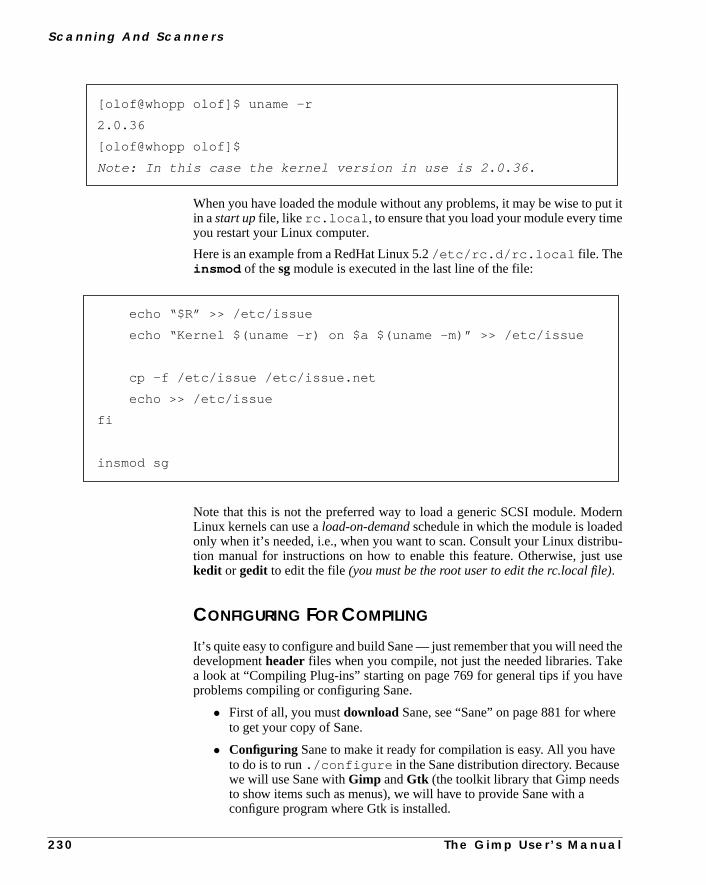
S c a n n i n g A n d S c a n n e r s
ut ite
erndbu-use
thekeve
e
e
When you have loaded the module without any problems, it may be wise to pin astart upfile, like rc.local , to ensure that you load your module every timyou restart your Linux computer.
Here is an example from a RedHat Linux 5.2/etc/rc.d/rc.local file. Theinsmod of thesg module is executed in the last line of the file:
Note that this is not the preferred way to load a generic SCSI module. ModLinux kernels can use aload-on-demandschedule in which the module is loadeonly when it’s needed, i.e., when you want to scan. Consult your Linux distrition manual for instructions on how to enable this feature. Otherwise, justkedit or gedit to edit the file(you must be the root user to edit the rc.local file).
CONFIGURING FOR COMPILING
It’s quite easy to configure and build Sane — just remember that you will needdevelopmentheader files when you compile, not just the needed libraries. Taa look at “Compiling Plug-ins” starting on page 769 for general tips if you haproblems compiling or configuring Sane.
• First of all, you mustdownload Sane, see “Sane” on page 881 for wherto get your copy of Sane.
• Configuring Sane to make it ready for compilation is easy. All you havto do is to run./configure in the Sane distribution directory. Becausewe will use Sane withGimp andGtk (the toolkit library that Gimp needsto show items such as menus), we will have to provide Sane with aconfigure program where Gtk is installed.
[olof@whopp olof]$ uname -r
2.0.36
[olof@whopp olof]$
Note: In this case the kernel version in use is 2.0.36.
echo “$R” >> /etc/issue
echo “Kernel $(uname -r) on $a $(uname -m)” >> /etc/issue
cp -f /etc/issue /etc/issue.net
echo >> /etc/issue
fi
insmod sg
2 3 0 T h e G i m p U s e r ’ s M a n u a l

C h a p t e r 1 5
s
, it
ne
ery
• To find out if Gtk and Gimp are installed under/usr or /usr/local enter:which gimp , and this command will echo either/usr/bin/gimp or /usr/local/bin/gimp . You don’t need to tell Sane’sconfigure program anything. It will find Gimp and Gtk anyway.
• However, if you have installed Gtk and Gimp somewhere else, such a/opt/gimp , then you will have to provide the configure program withthat information. If you run into problems when you configure, you canexamine theconfig.log file present in the same directory asconfigure . You can also invokeconfigure with --help like this:
./configure --help
and configure will display all of its options.
Here is an example of how toextract andconfigure Sane:
If Gimp Is Not Installed In A Standard DirectoryIf you have Gimp in a standard location, i.e.,/usr or /usr/local , Sane’s con-figure program will find Gimp automatically. When you have compiled Sanewill be able to function as a Gimp plug-in.
If you have Gimp installed somewhere else, such as/opt/gimp , Sane’s config-ure program will not find Gimp, and the possibility to compile and later run Saas a plug-in to Gimp will be disabled.
However, if both Gimp and Gtk are installed under the same location, this is veasy to fix. Just edit theMakefile in the frontend directory in Sane with gedit(or kedit). You’ll find frontend/Makefile in the top directory in the Sanedistribution directory.
You have to add-DHAVE_LIBGIMP_GIMP_H in the CPPFLAGSline and-lgimp in theGIMP_LIBS line.
Here is an example of how it looked after adding these command lines:
[olof@whopp olof]$ gunzip sane-1.0.1.tar.gz
[olof@whopp olof]$ tar xvf sane-1.0.1.tar
[olof@whopp olof]$ cd sane-1.0.1
[olof@whopp sane-1.0.1]$ ./configure \--with-gtk-prefix=/opt/gimp --disable-gtktest
T h e G i m p U s e r ’ s M a n u a l 2 3 1

S c a n n i n g A n d S c a n n e r s
n do
brary238
en
Preparing For SecurityWell, we don’t want to jump ahead, but there are some adjustments you canow that will enable you to raise the security level later on.
You may havedependentlibraries innon-standardlocations, for example, Gimpand Gtk could be installed under/opt/gimp , andlibjpeg could be installedunder/usr/local .
After having raised thesecurityby enablingsgid (set group id on execution) onthe scanner program, the scanning program (e.g.,xscanimage) will not find allof the libraries that it needs, because they are located outside the standard lidirectories. Why? Well, when you read “Setting Device Permissions” on pageyou will understand what we are doing here.
• OnSolaris, outside standard libraries means outside /usr/lib or/lib .
• UnderLinux , you have to check the/etc/ld.so.conf file tofind out which standard directories will be searched for library files whthe scanning program starts.
The solution is to add the command-R/where-you-have-librarieswhen youlink your program.
In the following example we will include:
-R/usr/local/lib
in the LIBS line in the Makefile (in the frontenddirectory). Because we hadGtk and Gimp installed under/opt/gimp , we must also add-R/opt/gimp/lib to theGTK_LIBS line.
INCLUDES = -I. -I$(srcdir) -I$(top_builddir)/include -I$(top_srcdir)/include \
-I/usr/local/include -I/opt/gimp/lib/glib/include -I/opt/gimp/include -
I/usr/X11R6/include
DEFS = -DHAVE_CONFIG_H
CPPFLAGS = -D_GNU_SOURCE -DHAVE_LIBGIMP_GIMP_H \-DHAVE_LIBGIMP_GIMP_H
Note: Here is the line we changed. Notice that you must not removeany entries in the line, just add the “-DHAVE_LIBGIMP_GIMP_H” .You must also add -lgimp to the GIMP_LIBS line:
GIMP_LIBS = -lgimp
2 3 2 T h e G i m p U s e r ’ s M a n u a l

C h a p t e r 1 5
y ited).er
ams;
lags
tall
It’s very easy to find out if any libraries are missing. Just enterldd , for example,ldd xscanimage , after the program has been built and “sgid’ed”, andlddwill tell you which libraries the program can’t find.
All you have to do now is include the directory where the library is with a-R in the Makefile (in the frontend directory).
Run make clean and thenmake in the frontend directory. This will rebuildthe program and find the dependent libraries.
CompilingYou must havemake, gcc or cc (the compiler),ld, etc., in yourpath. UnderSolaris those tools are in the/usr/ccs/bin directory, and that directory mustbe in your path.
gccmust also be in your path, and you have to find out under which directoris installed (this depends on which precompiled version of gcc you downloadWhen you know the gcc directory (in this example, gcc was installed und/usr/local ), enter:
export PATH=/usr/ccs/bin:/usr/local/bin:$PATH
In Linux, this is no problem as long as you have installed the necessary progrthey will be in your path automatically.
If you have problems later on, when running Sane, you can add the following fwhen you run configure:
--disable-shared , --disable-dynamic and--enable-preload
Normally, you don’t need to do that under Linux or Solaris.
You are now ready to build and install Sane. The configuration above will insSane under/usr/local . To change it, use:
--prefix=/where/to/install/sane
Lets build and install Sane:
LIBS = -R/usr/local/lib -ldl -lsocket -lnsl -ljpeg -lintl -lm
GTK_LIBS = -L/opt/gimp/lib -L/opt/X11R6.3/lib/ \-R/opt/X11R6.3/lib/ -R/opt/gimp/lib -lgtk -lgdk -lglib \
-lXi -lXext -lX11 -lsocket -lnsl -lm
GIMP_LIBS = -lgimp
[olof@whopp sane-1.0.1]$ make
[olof@whopp sane-1.0.1]$ su root -c “make install”
Note: You must provide the root password here .
T h e G i m p U s e r ’ s M a n u a l 2 3 3

S c a n n i n g A n d S c a n n e r s
9 to
net-
e of
Sane will now hopefully be installed under/usr/local . If you have experi-enced any problems, you can read “Compiling Plug-ins” starting on page 76get more information on how to compile in general.
RUNTIME CONFIGURE
Before you can use Sane to scan on your local workstation (we will discusswork scanning under “Network Access” on page 241), you will need toconfigureSane. Sane’s configure files are located under/usr/local/etc/sane.d/ ifyou installed it under/usr/local .
To help you find out which device your scanner is attached to, and what typscanner you have, the Sane team has created a program calledfind-scanner. Thisprogram is located in thetoolsdirectory in the Sane distribution directory (in thetools directory in the main directory where you compiled Sane).Find-scan-ner will locate your scanner and find out what model it is.
Here is how it can look under Solaris:
And here is how it can look under Linux:
[olof@whopp sane-1.0.1]$ su
Note: You must provide the root password here.
[root@whopp sane-1.0.1]# tools/find-scanner
# You may want to run this program as super-user to find all
# devices. Once you found the scanner devices, be sure to adjust# access permissions as necessary.
find-scanner: found processor “HP C5100A R032” at device \/dev/scg0c
find-scanner: found scanner “UMAX Astra 1200S V1.3” at device \/dev/scg0e
[olof@whopp sane-1.0.1]$ su
Note: You must provide the root password here.
[root@whopp sane-1.0.1]# tools/find-scanner
# You may want to run this program as super-user to find all
# devices. Once you found the scanner devices, be sure to adjust# access permissions as necessary.
find-scanner: found processor “HP C5100A R032” at device \/dev/sg0
find-scanner: found scanner “UMAX Astra 1200S V1.3” at device \/dev/sg1
2 3 4 T h e G i m p U s e r ’ s M a n u a l

C h a p t e r 1 5
to
e
ouess
This tells us that we have anHP scanner under/dev/scg0c (or /dev/sg0for Linux) and aUMAX scanner under/dev/scg0e (or sg1 for Linux). Allwe have to do now is configure Sane to query/dev/scg0c for the HP scannerand/dev/scg0e for the UMAX scanner. Before you proceed, it is advisabletest if Sane works as it should:cd down to/usr/local/etc/sane.d/ andas root user (su root ) editdll.conf and comment out every line except thpnm line.
Here is an example of a bit of the file:
Now, run/usr/local/bin/xscanimage as user root:
If Sane works (the dynamic loading of modules), a dialog will appear where ycan set which pnm device to use. Click OK and continue. You will now accxscanimage’s main scanner window.
#microtek2
#mustek
#pint
pnm
#qcam
#ricoh
#s9036
[olof@whopp olof]$ xhost localhost
localhost being added to access control list
[olof@whopp olof]$ su
Note: You must provide the root password here.
[root@whopp olof]# /usr/local/bin/xscanimage --display \localhost:0.0
T h e G i m p U s e r ’ s M a n u a l 2 3 5

S c a n n i n g A n d S c a n n e r s
the
maxilityple, a
ity
ad
If these dialogs appear, Sane is probably working just fine. Now, editdll.conf file and remove the# from hp and umax and comment outpnm. Ifyou have another brand of scanner you should of course not use the hp or uentries; instead, remove # from your scanner brand. Also check the compatiblist, see the Sane scanner list on page 870, because sometimes, for examNikon scanner is really a UMAX scanner with a Nikon brand. The compatibillist will tell you exactly which entry to uncomment.
Now, it’s time to use the device information extracted fromfind-scanner . Ifyou installed Sane under/usr/local/ you will find a config file for allbackends (scanners) supported by Sane in the/usr/local/etc/sane.ddirectory (otherwise,/where/you/installed/Sane/etc/sane.d/ ).
In our case, we have to edithp.conf and umax.conf . The changes in theconfig file regard what device that the scanner is attached to, such as/dev/sg1(Linux) or /dev/scg0c (Solaris). Note that if you uncommented epson insteof hp and umax in thedll.conf file, then you have to edit theepson.conffile instead.
Figure 15.1 Thedevice dialog
Figure 15.2 Xscanimage’s main scannerwindow for the pnm test interface
2 3 6
T h e G i m p U s e r ’ s M a n u a l
C h a p t e r 1 5
testlly
Here is an example from ourumax.conf file:
The last line tells the scanner that your scanner is attached to/dev/scg0e . Nor-mally when you install Sane from scratch, this line will say/dev/scanner . Allyou have to do is exchange/dev/scanner with your interface.
Still as root, run/usr/local/bin/xscanimage . Because we have twoscanners, we will get a device dialog just like the one we got for the pnmdevices. Just click OK; this tests that everything is working. If everything is fufunctional, you will access the main scanner interface for your scanner.
scsi UMAX * Scanner
scsi LinoHell Office
scsi LinoHell Office2
scsi LinoHell SAPHIR2
scsi Nikon AX-210
/dev/scg0e
Figure 15.3 Thedevice dialog for theUMAX scanner and theHP slide scanner
Figure 15.4 The main scanner window forthe UMAX interface
T h e G i m p U s e r ’ s M
a n u a l 2 3 7
S c a n n i n g A n d S c a n n e r s
auseoter-the
atcan
y
ess toeand..
nd
ys tot is tooneand a
SETTING DEVICE PERMISSIONS
The problem that we have to face now is that no ordinary user can scan, bec/dev/sg1 or /dev/scg0 is owned by root, and only root has the authority tread and write. Under Linux, this is no big problem, but under the Solaris inface, it’s a bit more troublesome. All you have to do under Linux is changeaccess rights from/dev/sg1 to 777 , and everyone will be able to scan.
Here is how to do it in a shell:
[olof@whopp olof]$ su root -c “chmod 777 /dev/sg1”
Note: You have to type the root password here.
The problem is that if you do the same on the Solaris interface,everyonewill havethe right to write and read toeverydevice on that SCSI interface. This means thif you have SCSI disks on the same interface, someone (or you by mistake)send an“erase everything”command to one of your disks. As you probablunderstand, this is not a good solution for solving this problem.
The answer is to create a special user and group that have read and write accthe device, e.g.,/dev/scg0 . Then, you let the system automatically set thgroup ID to that special scanner group every time you invoke a scanner commWe must enable sgid (set group id on execution) on every scanner program
This is also the safe way to do it under Linux. Also, you will need the user agroup to enable network scanning later on.
Adding a user is beyond the scope of this book, because there are a lot of wamanage users. Please consult your operating system’s manual. A good hinread theuseradd manual page. Remember to lock the account so that nocan log in as the new user. Let’s say that you have created a new user Sane,group Sane.
Under Linux, enter:
[olof@whopp olof]$ su
Note: You must provide the root password here.
[root@whopp olof]# chown sane:sane /dev/sg1
[root@whopp olof]# chmod 660 /dev/sg1
[root@whopp olof]# chown root:sane /usr/local/bin/xscanimage
[root@whopp olof]# chmod 2755 /usr/local/bin/xscanimage
[root@whopp olof]# chown root:sane /usr/local/bin/scanimage
[root@whopp olof]# chmod 2755 /usr/local/bin/scanimage
[root@whopp olof]# chown root:sane /usr/local/bin/xcam
[root@whopp olof]# chmod 2755 /usr/local/bin/xcam
2 3 8 T h e G i m p U s e r ’ s M a n u a l

C h a p t e r 1 5
me
we
ro-
r:
riesForng,
Doing the same thing under Solaris will include finding out the real device naof scg0 . Solaris keeps all real devices under/devices . The /dev directoryonly holds symbolic links to the real device.
This example will show you how to find out the real device name. Notice thatdo it onscg0 . The “e” in scg0e is only the SCSI id; “e” in this case means thatour scanner has SCSI id 4.
The rest is like the Linux example. You can now try to run the xscanimage pgram as an ordinary user. If you added the right directories with the-R flag whenyou compiled Sane, everything will work fine. But you may get this kind of erro
This means that when you compiled xscanimage, you forgot to add all directo(with the-R flag) that have libraries that xscanimage needs. (See “PreparingSecurity” on page 232). To find out whether any more libraries are missiinvoke ldd , like this:
[olof@whopp olof]$ ls -l /dev/scg0
lrwxrwxrwx 1 root other 81 Apr 19 14:53 /dev/scg0 ->
../devices/iommu@f,e0000000/sbus@f,e0001000/espdma@f, \
400000/esp@f,800000/scg@0,0:
Now we chown and chmod the real interface.
Note: “\” means that there is no line break.
[olof@whopp olof]$ su
Note: You must provide the root password here.
[root@whopp olof]# chown sane:sane /devices/iommu@f, \
e0000000/sbus@f,e0001000/espdma@f,400000/esp@f,800000/scg@0,0:
[root@whopp olof]# chmod 660 /devices/iommu@f, \
e0000000/sbus@f,e0001000/espdma@f,400000/esp@f,800000/scg@0,0:
ld.so.1: /opt/gtk1/bin/xscanimage fatal: libjpeg.so.62: can’t \open file: errno=2 Killed
T h e G i m p U s e r ’ s M a n u a l 2 3 9

S c a n n i n g A n d S c a n n e r s
ies
m.
thee
2.
As you see, only the jpeg library wasn’t found, but naturally, many more librarcould have been missing. You’ll never know, until you runldd on the program.
Now, you must find out where the missing library is installed on your systeWhen you have that information, you can rebuild the scanner program:cd to theSane distribution directory (i.e., the directory where you build Sane). Editfrontend/Makefile and include the missing directory (the one where thjpeg library is) with a-R flag, as you did in “Preparing For Security” on page 23
When you have edited thefrontend/Makefile , enter:
[olof@tinyjump olof]$ ldd /opt/gtk1/bin/xscanimage
libsane.so.1 => /opt/gtk1//lib/libsane.so.1
libgimp.so.1 => /opt/gtk1//lib/libgimp.so.1
libgtk.so.1 => /opt/gtk1//lib/libgtk.so.1
libgdk.so.1 => /opt/gtk1//lib/libgdk.so.1
libglib.so.1 => /opt/gtk1//lib/libglib.so.1
libXi.so.6.0 => /opt/X11R6.3/lib//libXi.so.6.0
libXext.so.6.3 => /opt/X11R6.3/lib//libXext.so.6.3
libX11.so.6.1 => /opt/X11R6.3/lib//libX11.so.6.1
libsocket.so.1 => /usr/lib/libsocket.so.1
libnsl.so.1 => /usr/lib/libnsl.so.1
libm.so.1 => /usr/lib/libm.so.1
libdl.so.1 => /usr/lib/libdl.so.1
libjpeg.so.62 => (not found)
libintl.so.1 => /usr/lib/libintl.so.1
libc.so.1 => /usr/lib/libc.so.1
[olof@whopp sane-1.0.1]$ cd frontend && make clean && make
[olof@whopp frontend]$ su -c “make install”
Note: You must provide the root password here.
2 4 0 T h e G i m p U s e r ’ s M a n u a l

C h a p t e r 1 5
-d and
in
work.thiset-
sts
in)the
the
s
After that, you have to runchmod andchown in the scanner programs (the permission and owner of the files are not the same, because you have recompileinstalled them):
Sane should work now. If it fails anyway, you’ll have to check everything agaand make sure that you didn’t make any mistakes.
NETWORK ACCESS
One of the most amazing capacities of Sane is that you can scan over the netIn fact, every Sane-controlled scanner can be a network scanner. To makework, you have to configure both the clients (the workstations that will use the nwork scanner) and the Sane server (i.e., the scanner server).
This involves:
• Setting up network access rules for Sane
• Configuring server start-up through the inetd super server
• Configuring your scanner clients to request scanning from the right ho
Inetd — The Super ServerThe easiest way to create a Sane network server is to useinetd. Inetd is the serverthat provides you with Telnet (or rlogin). Every time you make a Telnet (or rlogto a host, the inetd server on that host starts the Telnet (or rlogin) server onsame host to answer your Telnet (or rlogin) demand.
To enable thesanedscanner server to start (on client request), you have to edit/etc/inetd.conf file by addingsanedas a server thatinetdshould start whena client wants to scan over the network.
You also have to edit the/etc/services file on both clients and Sane serverto include the new scanner service.
[olof@whopp olof]$ su
Note: You must provide the root password here.
[root@whopp olof]# chown sane:sane /dev/sg1
[root@whopp olof]# chmod 660 /dev/sg1
[root@whopp olof]# chown root:sane /usr/local/bin/xscanimage
[root@whopp olof]# chmod 2755 /usr/local/bin/xscanimage
[root@whopp olof]# chown root:sane /usr/local/bin/scanimage
[root@whopp olof]# chmod 2755 /usr/local/bin/scanimage
[root@whopp olof]# chown root:sane /usr/local/bin/xcam
[root@whopp olof]# chmod 2755 /usr/local/bin/xcam
T h e G i m p U s e r ’ s M a n u a l 2 4 1

S c a n n i n g A n d S c a n n e r s
ingy in
ecu-
uldadd
r’spid
There are inetd serverswith tcp wrappers (standard on most Linux distribu-tions) andwithout tcp wrappers. (Tcp wrappers are used as a way of controllthe access rights of all your inetd controlled servers). The configuration entrthe inetd.conf file is slightly different in these two versions.
This is how it will look in /etc/inetd.conf if you don’t have tcp wrappers:
and this is how it looks when you have tcp wrappers:
Just add the appropriate line at the end of your/etc/inetd.conf file, usingyour favorite editor such as kedit or gedit. Remember that you must beroot whenyou perform this operation. Did you also notice thesane userandsane groupin theinetd.conf lines above? It is not very smart to runsanedas root. If you do youwill open security holes that hackers can use to compromise the workstation srity.
Note that Solaris only acceptsuser,not group in the /etc/inetd.conf file.Just remove “.sane ” from the inetd.conf lines above.
The /etc/services FileThe next step is to add a line in/etc/services to tell which port to use whenyou want Sane to start up (the closest non-technical comparison would be adoor;in order to talk to the right person, you must know on which door you shoknock). This needs to be done on both clients and servers. Here is the line toto the end of your/etc/services file :
All you have to do now is restart theinetd server. This is done by sending aSIGHUPsignal to the server. First, you have to find out the running inetd servepid (every program running on a UNIX-like computer has a unique numberfor identification). This is how you do it:
sane stream tcp nowait sane.sane /usr/local/sbin/saned saned
sane stream tcp nowait sane.sane /usr/sbin/tcpd/usr/local/sbin/saned
sane 6566/tcp # SANE network scanner daemon
2 4 2 T h e G i m p U s e r ’ s M a n u a l

C h a p t e r 1 5
if-
n.
Notice that it is theroot line that you should read; theolof line is simply meusing grep to reach forinetd in the program listing. Now, we will send theSIGHUPsignal, and here is how to do it. Notice that your pid number may be dferent than the one in these examples:
Access ControlThere are now three ways of allowing hosts to access thesaned server.
• saned.conf
• /etc/hosts.equiv
• /etc/hosts.allow and/etc/hosts.deny if you have tcpwrappers installed
You can use any of these methods, but/etc/hosts.equiv is the one that ismost insecure. Thesaned.conf file present under/usr/local/etc/sand.d/saned.conf must be edited both for plainsaned.conf accesscontrol and for tcp wrapper access control. For plainsaned.conf access con-trol, at the end of the file, simply add all the hosts that should be able to sca
Under Linux
[olof@whopp olof]$ ps aux | grep inetd
olof 10033 0.0 0.2 836 348 p9 S 21:47 0:00 grep inetd
root 290 0.0 0.0 776 76 ? S Apr 24 0:00 inetd
Under Solaris
[olof@tinyjump olof]$ ps -ef | grep inetd
Under Linux
[olof@whopp olof]$ su root -c “kill -SIGHUP 290”
Note: You have to provide the root password here
Under Solaris
[olof@whopp olof]$ su root -c “kill -SIGHUP 112”
Note: You have to provide the root password here
T h e G i m p U s e r ’ s M a n u a l 2 4 3

S c a n n i n g A n d S c a n n e r s
ent):
r,
nfig-bout
troltheers
Here is an example of how it may look (host names are naturally site depend
Here, we have enabledlocalhost (always wise to do that) plus some othehost within thefrozenriver.nu domain. If you don’t use long hostnamesyou only have to specify the short name; for example,whopp.frozenri-ver.nu will be written as “whopp” if you use short hostnames. The# shows thatthe line is a comment, and will therefore be ignored by the saned server.
If you have tcp wrappers installed, we recommend that you use them. The couration of tcp wrappers is beyond the scope of this book, but you can read ait in the man pages; enterman tcpd andman -S 5 hosts_access . Thehost_access man page will describe in detail how to set up host access conwith tcp wrappers. If you have tcp wrappers that haven’t configured yet, now istime to do it. The only thing you have to do after you have configured tcp wrappis add a+ sign at the end ofsaned.conf .
# matching is NO LONGER case-sensitive.
#
#scan-client.somedomain.firm
#localhost
#
# NOTE: /etc/inetd.conf and /etc/services must also
# be properly configured to start the saned daemon as
# documented in saned(1), services(4) and inetd.conf(4)
#
# for example, /etc/services might contain a line:
# sane 6566/tcp # network scanner daemon
#
# and /etc/inetd.conf might contain a line:
# sane stream tcp nowait root /usr/local/sbin/saned saned
whopp.frozenriver.nu
tinyjump.frozenriver.nu
ultra.frozenriver.nu
niceriver.frozenriver.nu
2 4 4 T h e G i m p U s e r ’ s M a n u a l

C h a p t e r 1 5
in. It’s
anly
lient)t
ere
anner
m-
etd
sh-t all
Here is an example of what the file will look like:
The/etc/hosts.equiv file is a very unsafe way of controlling host accessSane (or for that matter, all host access control to your workstation or server)a fast lane to lowering the security of your workstation.
Its purpose is to make it easy to log in to different UNIX workstations withinUNIX domain. The function makes sense if you are in a well-secured UNIX-onetwork.
Suppose that a user name is present on a remote UNIX computer (host, cUNIX-like computer and onyour workstation (server). If the remote login hosis specified in the/etc/hosts.equiv file, this user will be able to make aremote login to your workstation without providing a password. Obviously, this a security concern with the file. We recommend that you don’t use a/etc/hosts.equiv file if your computer is connected to the Internet.
We assume that you will now have selected a safe way to enable secure scaccess to your workstation.
Network Client ConfigurationStart by installing Sane on the network client, as we did in “Configuring For Copiling” on page 230. You also have to edit the/etc/services file, as we didin “The /etc/services File” on page 242, but you don’t have to restart the inserver.
Now, you have to edit the/usr/local/etc/sane.d/dll.conf file asroot with your favorite editor, such as gedit or kedit. You have to remove the hamark “#” that is present in the net line. It’s also recommended to comment ouother lines with a hashmark. Here is how ourdll.conf file looks at one of ourclients (workstations):
## NOTE: /etc/inetd.conf and /etc/services must also
# be properly configured to start the saned daemon as
# documented in saned(1), services(4) and inetd.conf(4)
#
# for example, /etc/services might contain a line:
# sane 6566/tcp # network scanner daemon
#
# and /etc/inetd.conf might contain a line:
# sane stream tcp nowait root /usr/local/sbin/saned saned
+
T h e G i m p U s e r ’ s M a n u a l 2 4 5

S c a n n i n g A n d S c a n n e r s
ane. Younamerver.
r’s
ld
The next file you have to edit is the/usr/local/sane.d/net.conf file. Itis in this file that you specify which servers to call when you want to scan. Scan’t guess which hosts are provided with the Sane network scanning servicecan specify scanners on the server, but we suggest that you just put the hostthere, which will enable you to access all scanners on the Sane scanner se
This is an example of a clientnet.conf file:
If you use a long hostname, you have to exchangetinyjump.frozenri-ver.nu for tinyjump (naturally the name should match your Sane servehostname).
You are now ready to test the network scanning with thescanimage program.Putting an-L flag in this command will list all available scanners, and you shoube able to see your network scanner.
# enable the next line if you want to allow access through the net
net
#abaton
#agfafocus
#apple
#artec
#canon
#coolscan
#dc25
#dc210
#dmc
#epson
# This is the net config file. Each line names a host to attach# to. If you list “localhost” then your backends can be accessed# either directly or through the net backend. Going through the# net backend may be necessary to access devices that need special# privileges.
# localhost
tinyjump
2 4 6 T h e G i m p U s e r ’ s M a n u a l

C h a p t e r 1 5
nner
iselyd youaneot aswilload-
iling.n
isechave
duchat
This is how it looks on our site:
If you get a similar list that shows the scanner(s) available on the Sane scaserver, you will know that network scanning is working.
INSTALLING XSANE
Well, we could start using Sane right away. The default GUI to Sane whichcalledxscanimage, is nice, but there is a program that is even better — namXsane. Xsane has several advantages over xscanimage. It’s easier to use ancan, for example, save gamma correction settings. Another nice thing with Xsis that it allows you to use your scanner as a copy machine. Xscanimage is nsophisticated; it’s a bit more powerful, but also harder to use. Therefore, wego ahead and show you how to configure and compile Xsane. Start by downling Xsane; see “Sane” on page 881 for where to get your copy.
Configuring And CompilingXsane follows the same path as Sane when it comes to configuring and compIf you run into difficulties, please take a look at “Compiling Plug-ins” starting opage 769.
Configuring Xsane to make it ready for compilation is easy. All you have to dorun ./configure in the Xsane distribution directory. Because we will usXsane with Gimp and Gtk (the toolkit library that Gimp needs to show items suas menus), we will have to provide Sane with a configure program where we hGtk installed. If Gtk and Gimp are installed under/usr or /usr/local run-ning the commandwhich gimp will render in either/usr/bin/gimp or /usr/local/bin/gimp .
You don’t need to tell Xsane’s configure program anything; it will find Gimp anGtk anyway. But if you have installed Gtk and Gimp under another directory, sas/opt/gimp , then you will need to provide the configure program with thinformation.
[olof@whopp olof]$ /usr/local/bin/scanimage -L
device `net:tinyjump:umax:/dev/scg0e’ is a UMAX Astra 1200S \flatbed scanner
device `net:tinyjump:hp:/dev/scg0c’ is a Hewlett-Packard C5100A \flatbed scanner
T h e G i m p U s e r ’ s M a n u a l 2 4 7
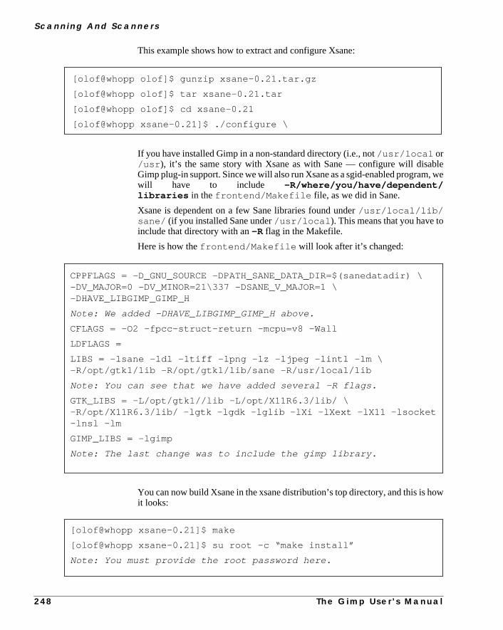
S c a n n i n g A n d S c a n n e r s
le, we
ow
This example shows how to extract and configure Xsane:
If you have installed Gimp in a non-standard directory (i.e., not/usr/local or/usr ), it’s the same story with Xsane as with Sane — configure will disabGimp plug-in support. Since we will also run Xsane as a sgid-enabled programwill have to include -R/where/you/have/dependent/libraries in thefrontend/Makefile file, as we did in Sane.
Xsane is dependent on a few Sane libraries found under/usr/local/lib/sane/ (if you installed Sane under/usr/local ). This means that you have toinclude that directory with an-R flag in the Makefile.
Here is how thefrontend/Makefile will look after it’s changed:
You can now build Xsane in the xsane distribution’s top directory, and this is hit looks:
[olof@whopp olof]$ gunzip xsane-0.21.tar.gz
[olof@whopp olof]$ tar xsane-0.21.tar
[olof@whopp olof]$ cd xsane-0.21
[olof@whopp xsane-0.21]$ ./configure \
CPPFLAGS = -D_GNU_SOURCE -DPATH_SANE_DATA_DIR=$(sanedatadir) \-DV_MAJOR=0 -DV_MINOR=21\337 -DSANE_V_MAJOR=1 \-DHAVE_LIBGIMP_GIMP_H
Note: We added -DHAVE_LIBGIMP_GIMP_H above.
CFLAGS = -O2 -fpcc-struct-return -mcpu=v8 -Wall
LDFLAGS =
LIBS = -lsane -ldl -ltiff -lpng -lz -ljpeg -lintl -lm \-R/opt/gtk1/lib -R/opt/gtk1/lib/sane -R/usr/local/lib
Note: You can see that we have added several -R flags.
GTK_LIBS = -L/opt/gtk1//lib -L/opt/X11R6.3/lib/ \-R/opt/X11R6.3/lib/ -lgtk -lgdk -lglib -lXi -lXext -lX11 -lsocket-lnsl -lm
GIMP_LIBS = -lgimp
Note: The last change was to include the gimp library.
[olof@whopp xsane-0.21]$ make
[olof@whopp xsane-0.21]$ su root -c “make install”
Note: You must provide the root password here.
2 4 8 T h e G i m p U s e r ’ s M a n u a l

C h a p t e r 1 5
onvery
onif-
withp’snt
ikethe
Itsell
notribu-
such.
f
If you experience any problems, please read “Configuring For Compiling”page 230, because the way of configuring and compiling described there issimilar.
Installing On A Server And A Network ClientThe last thing you need to do before using Xsane is tosgidthe xsane program file.Here is how you do it (it is just like what we did for Sane’s program files):
You can now try to run Xsane as an ordinary user. If you want to use Xsanescanner network clients, you will have to install Xsane there as well. It’s no dferent from installing it on the Sane server, which we just did.
USING SANE IN GIMP
You can, of course, use Sane (or more precisely,xscanimageandXsane) as astand-alone program, but using Sane with Gimp is so much better. TogetherGimp, xscanimage and Xsane will be much more powerful, because all of Gimimage manipulation functions will be available. (The only exception is if you wato scan with a higher bit depth than 24 bit color or 8 bit grayscale.
Thexcam program, which also comes with Sane, is for use with equipment lConnectix QuickCam, according to the Sane web site. We will not go intousage of xcam in this book.
Scanimageis a CLI program, and we have used it to list available devices.field of application is, however, much wider. It can, for example, be used in shscripts to achieve all sorts of things. Since it can’t be used with Gimp, we willdiscuss it further. There is, however, a very good man page in the Sane disttion. If you have the Sane man pages in yourMANPATH, just enter the commandman scanimage to access this information.
INSTALLING THE PLUG-IN
To use Xsane and xscanimage as Gimp plug-ins, you must install them asThe easiest way (and the right way to do it) is to make a symbolic link fromxsc-animage/xsane to your Gimp plug-in directory. Here is how you do it (ocourse, the location of both Gimp plug-ins and Sane is site-specific):
[olof@whopp olof]$ su
Note: You must provide the root password here.
[root@whopp olof]# chown root:sane /usr/local/bin/xsane
[root@whopp olof]# chmod 2755 /usr/local/bin/xsane
T h e G i m p U s e r ’ s M a n u a l 2 4 9
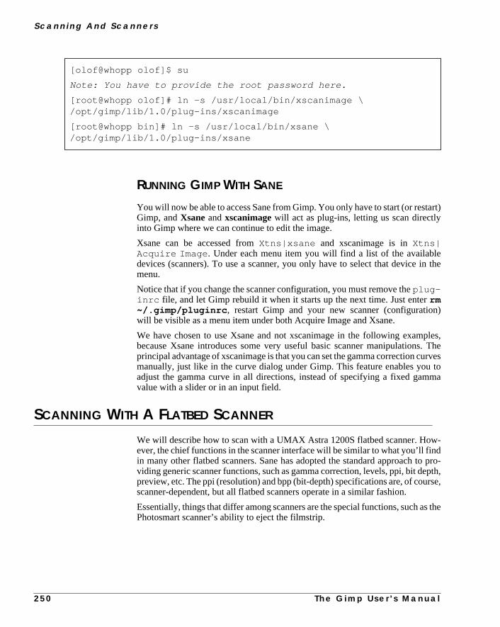
S c a n n i n g A n d S c a n n e r s
art)
ein the
n)
ples,. Theurves
toma
w-ndo pro-pth,rse,
s the
RUNNING GIMP WITH SANE
You will now be able to access Sane from Gimp. You only have to start (or restGimp, andXsaneandxscanimagewill act as plug-ins, letting us scan directlyinto Gimp where we can continue to edit the image.
Xsane can be accessed fromXtns|xsane and xscanimage is inXtns|Acquire Image . Under each menu item you will find a list of the availabldevices (scanners). To use a scanner, you only have to select that devicemenu.
Notice that if you change the scanner configuration, you must remove theplug-inrc file, and let Gimp rebuild it when it starts up the next time. Just enterrm~/.gimp/pluginrc , restart Gimp and your new scanner (configuratiowill be visible as a menu item under both Acquire Image and Xsane.
We have chosen to use Xsane and not xscanimage in the following exambecause Xsane introduces some very useful basic scanner manipulationsprincipal advantage of xscanimage is that you can set the gamma correction cmanually, just like in the curve dialog under Gimp. This feature enables youadjust the gamma curve in all directions, instead of specifying a fixed gamvalue with a slider or in an input field.
SCANNING WITH A FLATBED SCANNER
We will describe how to scan with a UMAX Astra 1200S flatbed scanner. Hoever, the chief functions in the scanner interface will be similar to what you’ll fiin many other flatbed scanners. Sane has adopted the standard approach tviding generic scanner functions, such as gamma correction, levels, ppi, bit depreview, etc. The ppi (resolution) and bpp (bit-depth) specifications are, of couscanner-dependent, but all flatbed scanners operate in a similar fashion.
Essentially, things that differ among scanners are the special functions, such aPhotosmart scanner’s ability to eject the filmstrip.
[olof@whopp olof]$ su
Note: You have to provide the root password here.
[root@whopp olof]# ln -s /usr/local/bin/xscanimage \/opt/gimp/lib/1.0/plug-ins/xscanimage
[root@whopp bin]# ln -s /usr/local/bin/xsane \/opt/gimp/lib/1.0/plug-ins/xsane
2 5 0 T h e G i m p U s e r ’ s M a n u a l
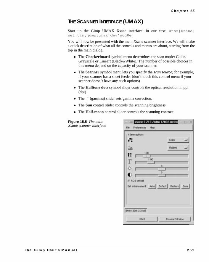
C h a p t e r 1 5
akethe
in
ur
THE SCANNER INTERFACE (UMAX)
Start up the Gimp UMAX Xsane interface; in our case,Xtns|Xsane|net:tinyjump:umax’dev’scg0e
You will now be presented with the main Xsane scanner interface. We will ma quick description of what all the controls and menus are about, starting fromtop in the main dialog.
• TheCheckerboard symbol menu determines the scan mode: Color,Grayscale or Lineart (Black&White). The number of possible choices this menu depend on the capacity of your scanner.
• TheScannersymbol menu lets you specify thescan source;for example,if your scanner has a sheet feeder (don’t touch this control menu if yoscanner doesn’t have any such options).
• TheHalftone dots symbol slider controls the optical resolution in ppi(dpi).
• The Γ (gamma) slider sets gamma correction.
• TheSun control slider controls the scanning brightness.
• TheHalf-moon control slider controls the scanning contrast.
Figure 15.5 The mainXsane scanner interface
T h e G i m p U s e r ’ s M a n u a l 2 5 1

S c a n n i n g A n d S c a n n e r s
e
hetup,saveon-
w,en
irstoto
Below the sliders, you will find some buttons for scan enhancement:Auto,Default, RestoreandSave. If you uncheck theRGB default checkbutton, youcan set thegamma, brightnessandcontrastfor each RGB channel separately. Thinterface will then look like Figure 15.6 .
In the top menu bar, you’ll find three menus calledFile, PreferencesandHelp.Under File, you’ll find info about the Xsane creator and general info about tdevice you are using. In the Preferences menu, you’ll find entries for SeAdvanced and Standard options. You can also view a scanning histogram anddevice settings. We will talk more about these settings a bit later, but let us ccentrate on basic “Sane’ing” for a while.
The Preview WindowWe’re sure you know what a preview is meant for. To open the preview windopress thepreview button. (If you checked Save preview in the Preferences, thyou will see the last preview when you open the preview window.) When you fopen the preview window there will be nothing but a white board. Place a phon the document glass and pressAcquire Preview.
Figure 15.6 The Xsane scannerinterface when RGB default isunchecked
2 5 2 T h e G i m p U s e r ’ s M a n u a l

C h a p t e r 1 5
iewn doyyou
n-tion.nts
it’s
Sane will now make a rapid low-resolution scan of the photo. While the prevscan occurs, all options in Xsane will be grayed out, and the only thing you cais pressCancel Preview. We don’t recommend canceling the preview or another scan for that matter (it’s a bit buggy). Just let Sane finish the scan job;can always dump the image later on.
One of the advantages ofXsaneoverxscanimageis that you can preview howyour adjustments in the main window will affect the final scan. To limit the scaning area, click and drag the mouse in the preview window to create a selecYou will now see a dotted selection outline, and Sane will only scan the contewithin that rectangle.
When you are satisfied with your selection (a rough selection will do, becausemuch easier to crop the image in Gimp), press theScanbutton in the main dialog.Sane will now scan the image and display it in Gimp.
Figure 15.7 The Xsanepreview window
T h e G i m p U s e r ’ s M a n u a l 2 5 3

S c a n n i n g A n d S c a n n e r s
wellen-
ur willis
ma
mamp’s
ou
GBl.
ighulate
W)ner’s
om
e isto
can-
OptionsThe Preference menu offers both Standard options and Advanced options asas a Histogram option. Most options are quite scanner-specific, but we will mtion some of them.
• Use Custom Gamma Table:If your scanner supports hardwaregamma correction you can enable it with this button. Furthermore, if yoscanner supports more than 8 bit color, then the custom gamma tablemake the gamma correction with that number of bits. The conclusion that if your scanner supports more than 8 bpp and/or has hardware gamcorrection, then it’s a good idea to use it.
It’s also worth mentioning that xscanimage has more features dealing with gamcurves. The gamma curves in xscanimage are built up in the same way as GiCurves command (right-click|Image|Colors| Curves ).
• Bit depth 8 or 10 bpp: If you are using Xsane or xscanimage withinGimp, you can only use 8 bpp because Gimp only supports 8 bpp. If yscan with 10 bpp you will only get errors.
• Histogram: This works like Levels in Gimp (right-click|Image|Colors| Levels ). It’s a very useful option when you want tocorrect errors in both color and lightness. If you have unchecked the Rdefaults button, you can also set the histogram for each RGB channe
SCANNER MODES
Most flatbed scanners supportlineart, grayscale andcolor scanner modes.
LineartThe result of scanning in lineart mode is often unpredictable, so to retain a hlevel of detail, we suggest that you scan in grayscale mode, and then manipthe grayscale image byindexing to black and white.
Alternatively, useright-click|Image|Colors| Threshold orright-click|Image|Colors| Levels to gain better control of where theblack and white pixels end up in the lineart image.
GrayscaleGrayscale scan mode is, of course, useful if you want to scan grayscale (B&photos. Scan a grayscale image in color, and you have to worry about the scancolor balance. If you want to colorize the image later, it’s better to convert frgrayscale to RGB mode in Gimp.
Scanning a color image in grayscale mode is not unusual. If your color imagdestined to be printed in black-and-white, you might think that it is pointlessscan in color mode, but that’s not always true. It depends on how good your sner is.
2 5 4 T h e G i m p U s e r ’ s M a n u a l

C h a p t e r 1 5
thansion
thecanthennver-
youve aent
eand
youse-orThentirenc-inedral,ect
For example, a yellow color is perceived by the human eye as being lightera blue color with the same intensity (value). Gimp makes quite a good converfrom color to grayscale and compensates for the human factor by convertingyellow color to a brighter shade of gray than the blue color. If your scannermanage to produce an equally good or better grayscale image than Gimp,scan in grayscale mode. Otherwise, scan in color and make the grayscale cosion in Gimp.
ColorColor mode is color mode, and there’s not that much to say about it. Naturally,should be concerned about color correctness and dropout color, but if you habad scanner, we can only recommend that you try to correct it with the differcolor correction functions in Gimp.
AUTO CORRECTION
Xsane has a very useful feature calledAuto Adjust (the Auto button in the maindialog). Auto Adjust will correct a poorly exposed photo automatically in thscanning process. The correction calculations are based on the highlightsshadows of the selected part in the preview. It is therefore very important thatdon’t select any part of the white scanner lid. This auto function is even more uful when you want a particular part of an image to be correctly “exposed.” Fexample, you may want a person’s face to be correctly exposed in a portrait.trick is to select the face in the preview image, press Auto and then select the earea that you want to scan in the preview window. Of course, an Auto Adjust fution will never be able to correct an image with the same accuracy as a well-traprofessional. We use it as a starting point for further correction, but in geneAuto Adjust does a really great job and leaves us nothing or very little to corrmanually.
Figure 15.8 BeforeAuto Adjust
Figure 15.9 AfterAuto Adjust
T h e G i m p U s e r ’ s M a n u a l
2 5 5
S c a n n i n g A n d S c a n n e r s
faultrfec-ctionat is
mama
theyourillionrrec-
para-rding
to
nder-
entis
GAMMA CORRECTION
In our opinion, there is no scanning correction that is more important thangammacorrection. Most people believe that gamma correction is a correction of somein the scanner, but that’s not it. Gamma correction compensates for the impetions of output devices, such as computer monitors or printers. Gamma correis atonalcorrection (light/darkness), and it refers to a special gamma curve thused to perform that correction.
To find out which gamma correction is needed for your display, read “GamCalibration” on page 206. When you know that gamma value, drag the gamslider to that value. Your scan will now be gamma correct — the lightness inphoto will be the same on the original as on the scanned image displayed onmonitor. Notice that gamma correction will not make a bad picture good, it wonly correct it so it looks equally bad on your monitor. There are other correctfunctions to help improve your photos (gamma can naturally be used as a cotion function here, too, in the sense that you will alter the gamma tonotmatch yourmonitor).
TONAL CORRECTION
We have already discussed tonal correction to some extent in the previousgraph. We mentioned that setting the gamma value to the correct value accoto your monitor isn’t always that good. If the original image was overexposedbegin with, the scanned image will be equally overexposed, unless youlower thegamma value to compensate for the faulty exposure (and vice versa for an uexposed photograph).
When you scan older color photographs, you will often have to deal with differkinds of color tone problems. A well-known problem with aging photographs
Figure 15.10 With and without gamma correction — as you see,the difference is huge
2 5 6 T h e G i m p U s e r ’ s M a n u a l

C h a p t e r 1 5
naland
mathe
akerednly
ge,r the
aker or
pi
e
heion.
final
:1. Ifnt to
cantheno
iseith
100er-
that they often attain a tonal shift towards blue or red. To rectify unwanted toshift, you can uncheck the RGB default button in the main Xsane window,suppress the color channel that is overly dominant in the image. Move the gamcontrol slider of the channel that is overrepresented until you’re satisfied withresult.
If the photo’s tonal range shifts toward cold, blue shades, and you want to myour image look a bit warmer, then you should increase gamma value in thechannel (and also a little bit in the green channel). This technique is commoused to increase the warmth in the skin color of a model’s face.
Likewise, if you have a photo that you want to adjust toward a cooler color ranthen you should either increase the gamma value in the blue channel, or lowegamma in the red channel (or a combination of the two).
SCALING
When you talk about scaling and scanning, it’s not just a question of scaling to mthe image bigger; you must also consider the final output device (the printemonitor).
Let’s scan an ordinary 4x6 photo:
• If you decide to print that photo in a 1:1 scale with a resolution of 300 p(not dpi!) you will scan with a 300 ppi resolution.
• If you’d like to make the print twice as large as the original (2:1) using thsame resolution (300 ppi), then you need to scan with a 600 ppiresolution.
• If your final target is a web page with a 72 ppi resolution, then to get tsame size as the original photo, you have to scan with a 72 ppi resolut
• Likewise, if you want a 2:1 resolution, you have to scan at 144 ppi.
As you probably have understood by now, the scaling factor depends on theoutput.
Scaling LimitsUsing a 300 ppi scanner, you are not advised to scale an image more than 4you have a 600 ppi scanner, you can scale beyond that (but it is not sufficiescale 35mm slides).
Generally, the quality of the source (the photo) sets the limit for how much youscale an image. If the scanned photograph was of poor quality, you will seestructure, or grain, even with a relatively modest scaling. Obviously, there’spoint in including photographic artifacts such as grain and structure.
Any scaling beyond 4:1 using a 300 ppi scanner will only render in a high noratio in your image, so don’t think that you can scale a small photo (or slide) wa 300 ppi scanner.
A final big tip is that you should always scale with the scanner. Never scan atppi and then scale the image in Gimp. When you scale in Gimp, Gimp will int
T h e G i m p U s e r ’ s M a n u a l 2 5 7

S c a n n i n g A n d S c a n n e r s
scale
om
letiontheoule of
can aat is
polate (guess) what would be an appropriate color between pixels. So alwayswith the scanner!
SCANNING DRAWINGS AND PRINTED IMAGES
Scanning drawings and printed material involves artifacts such asmoiré patternsandaliasing effects. So, why does it look so bad when you scan an image frthe newspaper?
Moiré EffectsA book, magazine or newspaper is printed with a certainlpi (lines per inch), alsoknow asline frequency. According to digital sampling theory, you must sampat least twice the frequency of the source in order to capture accurate informaof the signal (in this case, the signal is the printed halftone dots). This is calledNyquist rate or Nyquist frequency. So, to capture a book printed in 150 lpi ymust scan it in at 300 ppi. Because most 300 ppi scanners aren’t really capabmaking true 300 ppi scans, it’s clear that such a scanner can’t be used to sbook printed in 150 lpi, because it is not capable of resolving the frequency thneeded to scan a 150 lpi source.
Figure 15.11 Before and after moiré correction
2 5 8 T h e G i m p U s e r ’ s M a n u a l
C h a p t e r 1 5
asou
nti-
thatof
willce
ce.hisllan
sing
ing
pro-nlyhatenr.
owerally
FIxing Up Moiré PatternsEven if you scan with the right resolution (300 ppi for a drawing or book that ha line frequency of 150 lpi) the moiré pattern problem will pop up again when yresize the image to make it fit your layout. The solution is to:
1. Add some Noise:(right-click|Filters|Noise| Noisify )
2. Then add a little Gaussian Blur:(right-click|Filters|Blur| Gaussian Blur (IIR) )
3. Then sharpen it up with Unsharp Mask (a lot):(right-click|Filters|Enhance| Unsharp Mask )
4. Now you can resize and print your image
The result isn’t perfect, but this is as good as it gets without running one of the amoiré programs available on the market.
AliasingHaving gained a basic knowledge of sampling frequency, you now understandthe same effect will occur when you scan a line drawing. A drawing consistslines, so imagine that we take all of those lines and calculate how many linesfill one inch. That is the “lpi” of the drawing. We must scan at a resolution twias big as that lpi to get an accurate result.
If you scan at a lower resolution, you will not resolve every detail of the sourThis may render lines in the drawing that weren’t there to start with. Tunwanted effect is calledaliasing, and is due to the fact that you can’t resolve aof the lines with such a low sampling frequency. The thin lines you see inaliased image do not represent the thinnest lines in the original; it’s an aliaeffect built up from several of the thinnest lines.
To learn more about lpi and printing, read “Pre-press And Color In Gimp” starton page 197.
SCANNING, THE WEB AND PRINTING
In the pre-press chapter (see page 197), we discussed printing from a morefessional point of view. But there are probably a lot of readers out there who ouse Gimp in a SOHO (Small Office, Home Office) environment. This means tyou will probably print to an inkjet printer with a “resolution” somewhere betwe300 dpi and 1,400 dpi, or perhaps you have a 300 dpi or 600 dpi laser printe
INKJET PRINTERS
Inkjet printers are quite different compared to laser printers, because they useFMscreening. FM screening (see “Why Doesn’t My Inkjet’s Print Look Like Half-tone Screens?” starting on page 214) can yield excellent results with a much limage resolution than the halftone dpi equivalent printer (note that you can’t re
T h e G i m p U s e r ’ s M a n u a l 2 5 9

S c a n n i n g A n d S c a n n e r s
age
ice
ftern injet
youn
00
urTo
’llrting
his.
an atage
you
lygesto a
talk about dpi when you discuss FM screening printers; see “Resolution” on p212).
A very rough rule of thumb is to use 125 ppi for every 300 dpi in the output dev(printer):
• 300 dpi inkjet printer; scan at 100 ppi
• 600 dpi inkjet printer; scan at 200 ppi
• 720 dpi inkjet printer; scan at 240 ppi
• 1,440 dpi inkjet printer; scan at 480 ppi
This table is not absolute; it’s a guideline that will help you get a good result arunning some tests. Also try lowering the scanning resolution when you scavery high resolution. For example, test to scan in 150 ppi for your 600 dpi inkprinter (instead of 200 ppi) and see if the result is acceptable. Naturally, ifdon’t use the full capacity of the printer (for example, if you print with a resolutioof 300 dpi on your 600 dpi printer) you should scan in 100 ppi, not 200 ppi.
When you print your image from Gimp, always make sure to use theppi optionin thePrinter dialog, and print with the scan resolution (e.g., 100 ppi for a 3dpi inkjet printer).
Laser PrintersThe list above covers inkjet printers, but it will most likely also apply to yoSOHO laser printer. However, it may be wise to try a few different resolutions.get a really good result, you need to figure out whatlpi your printer uses (or setan appropriate lpi if you have that option). The lpi will determine what ppi youneed for scanning and printing. Please read “Resolution And Image Size” staon page 200 to understand lpi and halftone printing.
Web PagesScanning for web publishing is generally very simple — just scan in 72 ppi. Tresolution will suffice for color photos that don’t require a high level of detail
If you scan items where detail is important, such as drawings, you have to sca much higher resolution (see “Scanning Drawings And Printed Images” on p258). This will produce huge web images, but if you scan in a lower resolutionwon’t be able to capture the details.
There is no simple solution to this problem. However, you can try this trick: Appthe Unsharp Mask filter (see “Unsharp Mask” on page 498) to enhance all edand details in the high-resolution image. After that, you can resize the imagemore web-friendly size.
2 6 0 T h e G i m p U s e r ’ s M a n u a l

C h a p t e r 1 5
oto-can
e (iftheraph.
yourcuslass.cts
orat then
OHOore.
youialtheet abox
you
SCANNING OTHER OBJECTS
If you have a flatbed scanner, you are of course not limited to scanning phgraphs. You can scan almost all flat objects, and with a few cunning tricks, youalso scan certain 3D objects.
It’s very easy to scan textures, but you may have to increase the exposure timthat option is available). Alternatively, you can add more light or increasegamma, since a texture doesn’t reflect as much light as a paper or a photog
We suppose that many of you have tried to photocopy 3-D objects, such ashand. The result is often quite disappointing. The reason for this is that the foof the scanner/copy machine is optimized to the distance of the document gAnother reason is that the amount of light doesn’t suffice to reflect 3-D objeback to the CCD.
If you want quality images of 3-D objects, then you should get a digital cameraeven better, a real 35mm camera. Good digital cameras are very expensive (time of writing), you will not get ahold of a good digital camera for less tha$1,200, and then we are talking about cameras that are good enough for Susage. If you want a professional camera, we’re talking about $10,000 or m
We mentioned that you could make some limited 3-D object scanning. Well,can, but the result will not be very professional (if you don’t want some speceffect). Still, to get a decent result, you have to put some sort of box overobject, don’t think that you can squeeze it in between the platen and the lid. Gcardboard box, preferably white inside. Place the object on the platen and theover the object. Now, you can try scanning using a slightly higher gamma thannormally would.
Here is the outcome of a scan using the “white box” technique:
Figure 15.12 Julius’ favoritepussycat “Missen” was placedon the scanner platen inside awhite shoebox. The result isquite pleasing, don’t you think?
T h e G i m p U s e r ’ s M a n u a l 2 6 1


P A R T
V More Gimp Functions• IMAGE MENU
• SELECTION MENU
• MODES
• LAYERS
• CHANNELS


C H A P T E R
16 Image MenuThe Image menu offers some of the most usefulimage manipulating functions in Gimp. In thischapter, we’re going to discuss what you can dowithin the image menu. The Colors, Channel Opsand Alpha submenus will be covered in separatechapters.

I m a g e M e n u
e
vertales,
le,
henB
orls”
h aber
”
RGB, GRAYSCALE AND INDEXED
Right-click|Image| RGB, right-click|Image| Grayscale andright-click|Image| Indexed are the three conversion options you havfor your image. Normally, you’ll work on an image in RGB color.
If you know that you want a grayscale or indexed image, you can easily conyour image later. Some commands, filters and Script-Fus require grayscwhereas others require RGB images.
Tip: All color information is irreversibly lost as soon as you convert to Grayscaand a lot of color information is lost when converting to indexed.
Most commands, filters and Script-Fus give poor results or no result at all wused onindexed images. If you are using an indexed image, convert it to RGimmediately, and don’t convert it back to indexed until you’re finished with it! Fmore information on RGB, grayscale and indexed images, review “Color Modestarting on page 187.
INDEXED PALETTE OPTIONS
Select theright-click|Image| Indexed command to convert an RGB orgrayscale image to indexed. This will open theIndexed Color Conversiondialogbox.
When you think of indexed images, you probably think about GIF images witmaximum of 256 colors. In general, however, you are free to specify any numof colors for an indexed image. To set the number of colors, press theGenerateoptimal palette radio button and type the number of colors you want into the# ofcolorsbox.
If you are doing web design, you should use theWWW-optimized palette to mapthe colors. You can also choose acustom palettefrom the drop-down list, or cre-ate aline art image by using a black/white palette for color mapping. TheEnableFloyd-Steinberg dithering option helps to make indexed images look “goodeven if they only include a few colors.
Without dithering With dithering
Figure 16.1 The difference between indexing without and with dithering
2 6 6 T h e G i m p U s e r ’ s M a n u a l
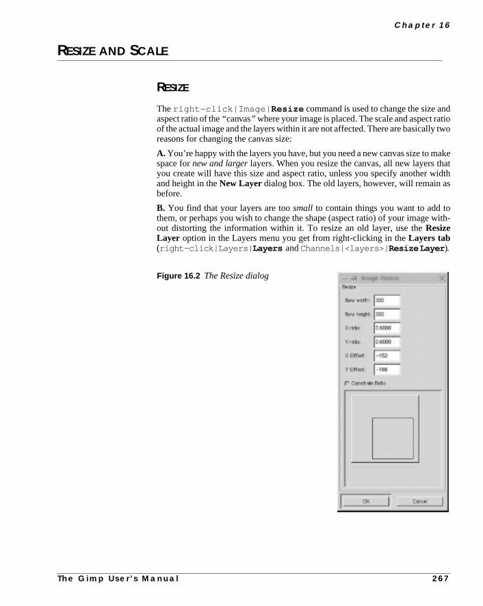
C h a p t e r 1 6
dtiotwo
akeatidth
s
with-
RESIZE AND SCALE
RESIZE
Theright-click|Image| Resize command is used to change the size anaspect ratio of the“ canvas” where your image is placed. The scale and aspect raof the actual image and the layers within it are not affected. There are basicallyreasons for changing the canvas size:
A. You’re happy with the layers you have, but you need a new canvas size to mspace fornew and largerlayers. When you resize the canvas, all new layers thyou create will have this size and aspect ratio, unless you specify another wand height in theNew Layer dialog box. The old layers, however, will remain abefore.
B. You find that your layers are toosmall to contain things you want to add tothem, or perhaps you wish to change the shape (aspect ratio) of your imageout distorting the information within it. To resize an old layer, use theResizeLayer option in the Layers menu you get from right-clicking in theLayers tab(right-click|Layers| Layers andChannels|<layers>| ResizeLayer ).
Figure 16.2 The Resize dialog
T h e G i m p U s e r ’ s M a n u a l 2 6 7

I m a g e M e n u
pectge
ng
llsize
.
lcale
ke it
ixel
inaleadp.
han-
The Resize Dialog OptionsThe dialog box displays a preview of what the proposed changes in size, asratio or offset will look like. Set where on the canvas you want to place the imaby dragging at the gray “image rectangle” in the dialog window, or by specifyia value in theX Offset and Y Offset fields.
If you check theConstrain Ratio checkbox, the proportions of the old canvas wibe kept. If you uncheck Constrain Ratio and then change the proportions, Rewill either crop or add a transparent area to the image to fit the new size.
SCALE
right-click|Image| Scale changes thesize and aspect ratio of yourimage. Scale makeseverything in your image larger or smaller, including layers
If you check theConstrain Ratio checkbox, the proportions of the old image wilbe kept. If you uncheck Constrain Ratio and then change the proportions, Swill stretch or compress the image to fit the new size, thusdistorting the image.
Interpolating With ScaleWhen you enlarge your image with Scale, Gimpinterpolatesthe new image. Thismeans that when you add new pixels to an image, as you must when you malarger, a process calledinterpolationwill calculate the color and value of the newpixels based on the properties of the neighbor pixels. That is, an additional pbetween black-and-white original pixels will get a gray color.
The consequence is that the enlarged image will look better than the origimage zoomed to the same size, but it will also lose sharpness and clarity. R“Interpolation” on page 100 to get more information about interpolation in Gim
HISTOGRAM
Right-click|Image| Histogram gives you valuablestatistical informa-tion on the channel values for an entire image or for a certain pixel range in a cnel.
Figure 16.3 The Scale dialog
2 6 8 T h e G i m p U s e r ’ s M a n u a l
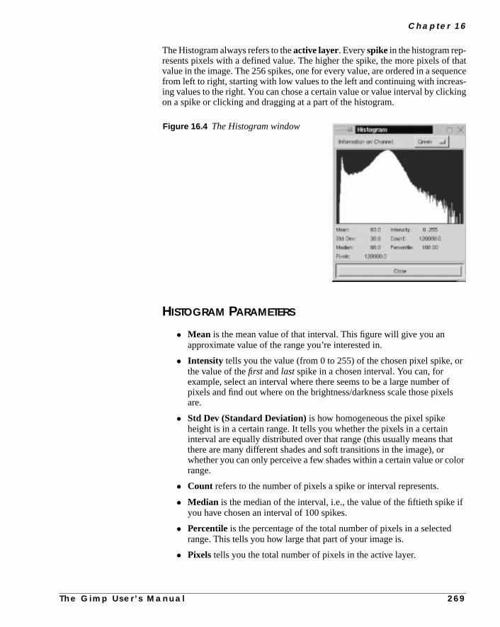
C h a p t e r 1 6
thatences-ing
or
fls
t
lor
if
The Histogram always refers to theactive layer. Everyspike in the histogram rep-resents pixels with a defined value. The higher the spike, the more pixels ofvalue in the image. The 256 spikes, one for every value, are ordered in a sequfrom left to right, starting with low values to the left and continuing with increaing values to the right. You can chose a certain value or value interval by clickon a spike or clicking and dragging at a part of the histogram.
HISTOGRAM PARAMETERS
• Mean is the mean value of that interval. This figure will give you anapproximate value of the range you’re interested in.
• Intensity tells you the value (from 0 to 255) of the chosen pixel spike, the value of thefirst andlast spike in a chosen interval. You can, forexample, select an interval where there seems to be a large number opixels and find out where on the brightness/darkness scale those pixeare.
• Std Dev (Standard Deviation) is how homogeneous the pixel spikeheight is in a certain range. It tells you whether the pixels in a certaininterval are equally distributed over that range (this usually means thathere are many different shades and soft transitions in the image), orwhether you can only perceive a few shades within a certain value or corange.
• Count refers to the number of pixels a spike or interval represents.
• Median is the median of the interval, i.e., the value of the fiftieth spikeyou have chosen an interval of 100 spikes.
• Percentile is the percentage of the total number of pixels in a selectedrange. This tells you how large that part of your image is.
• Pixels tells you the total number of pixels in the active layer.
Figure 16.4 The Histogram window
T h e G i m p U s e r ’ s M a n u a l 2 6 9

I m a g e M e n u
youthe
xed
the
g isirec-
r
tede.
und,
cut
ful
SAVE PALETTE
Right-click|Image| Save palette will create a palette of colors from anindexed image. When you are manipulating indexed images, this option letssavethe colors in your images, so that you can organize colors and easily pickcolor you want.
When you convert an image to indexed (right-click|Image| Indexed )you set the number of colors you want in theIndexed Color Conversiondialogbox. This also sets how many colors will be in a palette created from that indeimage.
CREATING A PALETTE FROM AN INDEXED IMAGE
Selectright-click|Image| Indexed to convert your image to indexed.Choose how many colors you want for your palette and type that number into# of colors: box. Click on theOK button and your image will be converted toindexed format.
Right-click|Image| Save palette will display theExport GIMP Pal-ettedialog. Type in a name for the palette, and press the OK button (the dialoalready in your personal palette directory so there’s no need to change the dtory).
Back on your image, press Ctrl+z toUndo the indexed conversion and return youimage to RGB.
Open the Color Palette dialog (with either right-click|Dialogs|Palette or File|Dialogs| Palette ). ChooseRefresh Palettesfrom theOps pull-down menu to refresh the palettes. Now, the palette you just creashould appear in the pull-down palette menu, and be available for you to us
TRANSFORMS
AUTOCROP
Right-click|Image|Transforms| Autocrop crops imagesautomati-cally. If you paint or paste something onto a large solid or transparent backgroyou may find that you have too much space around the image object.
Autocrop will crop your image so that everything but the important parts areaway. Note that if you work in alayer, Autocrop will crop the entire image withno concern for the other layers.
IMAGE
Right-click|Image|Transforms|Image| Rotate 270 or | Rotate90 lets yourotate the entireimageeither 270 degrees or 90 degrees. This is usefor changing scanned images to eitherlandscape or portrait mode.
2 7 0 T h e G i m p U s e r ’ s M a n u a l

C h a p t e r 1 6
ennd-
tsha,
rentpos-
ionsbut
LAYER
Right-click|Image|Transforms|Layer| Rotate 270 or Rotate90 allow you torotate a layer 270 degrees or 90 degrees. Remember that whyou rotate a large layer, portions of it will disappear outside of the image bouary.
MIRROR
Right-click|Image|Transforms| Mirror reflects your image as a mir-ror would. The difference betweenMirror and theFlip tool is that with Mirror,you can flip all layers at the same time by checking theMirror the whole imagecheckbox.
ROTATE
Right-click|Image|Transforms| Rotate provides a simple way torotate your image or selection 0, 90, 180 or 270 degrees.Rotate is very convenientfor reorienting scanned images.
ZEALOUS CROP
Right-click|Image|Transforms| Zealous Crop works much like theAutocrop filter, but there are some significant differences. While Autocrop cuaway any peripheral parts of the image that have no variation in color or alpZealous Cropmoves objects closer together(but not on top of each other) beforecutting.
When Zealous Crop finds objects of a different color on a solid or transpabackground in the same layer, it moves the objects as close to each other assible without them overlapping, so that they remain in the same relative positto each other. Zealous Crop lets you keep all of the objects in your image,reduces the size as much as is possible without scaling the image.
Zealous Crop works on all layers, but only compresses the objects in theactivelayer. Zealous Crop always crops theupper-leftpart of inactive layers, whileAutocrop cropsall layers in the position determined by the active layer.
T h e G i m p U s e r ’ s M a n u a l 2 7 1


C H A P T E R
17 Image Menu: ColorsThe Image menu offers some of the most usefulimage manipulating functions in Gimp. In thischapter, we’re going to discuss what you can dowith Colors in the Image menu.

I m a g e M e n u : C o l o r s
andtos.agespro-
els indiate
. Thecon-
COLORS
The first part of theImage|Colors menu deals with how image pixels aremapped to different RGB values; the second part deals with color correction;the third part contains useful filters for auto-correction of scanned phoRemember that you’re likely to get much better results adjusting scanned imin a professional image manipulation program like Gimp, than in the scannergram.
EQUALIZE
Right-click|Image|Colors| Equalize is often used to correct over-exposed or underexposed photos. Equalize finds the darkest and lightest pixthe image and sets the darkest value to black and the lightest to white. Intermecolors are then translated to the correspondinghistogram values on the newscale. This action adjusts the image pixel colors to a wider scale or spectrumresulting image is usually harder and much clearer, with more saturation andtrast, but often with less fine detail.
Figure 17.1Comparing dark andlight images beforeand after Equalizehas been invoked
Dark input Output after Equalize
Light input Output after Equalize
2 7 4 T h e G i m p U s e r ’ s M a n u a l

C h a p t e r 1 7
use
solidseiza-
h as
Youing
nusrs in
Tip: Equalize can be used to find “hidden” colors in old, fading photos, becacolors are also equalized.
For example, if there is a weak shade of green somewhere in a seeminglyblue area, Equalize will find it and strengthen it, while the blue color will lointensity. Sometimes, this results in colors looking a bit unnatural after equaltion. You might have to correct the image using color correction tools likeColorBalance.
For adjusting old photos, it is sometimes better to use other commands sucright-click|Image|Colors| Auto-Stretch HSV , Auto-Stretch Contrast and Normalize . Try all of them and see whichone is most suitable for your picture.
INVERT
Right-click|Image|Colors| Invert creates a color negative of yourimage (or a positive of your negative). Invert is very useful if you have aslidescanner, because then you never have to worry about expensive developing.need only develop the negative film, and then you can do your own developwith your computer.
The calculations are quite simple: The inverted RGB value of a pixel is 255 mithe former channel value. Read more about inverted or complementary colo“Complementary Or Inverted Colors” on page 194.
Figure 17.2 Invert isshown on the right side
T h e G i m p U s e r ’ s M a n u a l 2 7 5
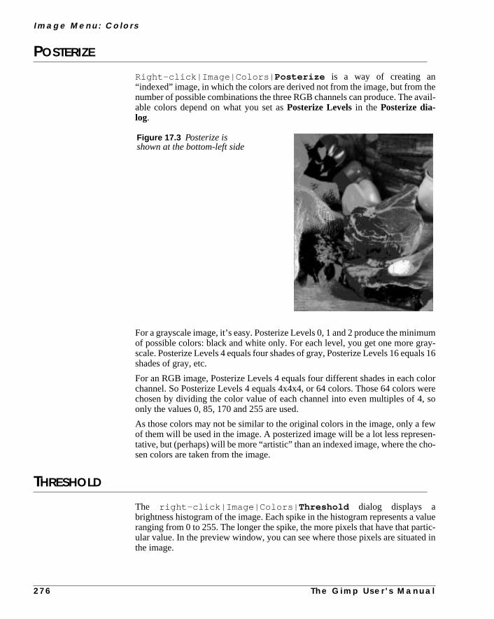
I m a g e M e n u : C o l o r s
thevail-
mumray-als 16
colorwere, so
ewen-ho-
valuertic-d in
POSTERIZE
Right-click|Image|Colors| Posterize is a way of creating an“indexed” image, in which the colors are derived not from the image, but fromnumber of possible combinations the three RGB channels can produce. The aable colors depend on what you set asPosterize Levelsin the Posterize dia-log.
For a grayscale image, it’s easy. Posterize Levels 0, 1 and 2 produce the miniof possible colors: black and white only. For each level, you get one more gscale. Posterize Levels 4 equals four shades of gray, Posterize Levels 16 equshades of gray, etc.
For an RGB image, Posterize Levels 4 equals four different shades in eachchannel. So Posterize Levels 4 equals 4x4x4, or 64 colors. Those 64 colorschosen by dividing the color value of each channel into even multiples of 4only the values 0, 85, 170 and 255 are used.
As those colors may not be similar to the original colors in the image, only a fof them will be used in the image. A posterized image will be a lot less represtative, but (perhaps) will be more “artistic” than an indexed image, where the csen colors are taken from the image.
THRESHOLD
The right-click|Image|Colors| Threshold dialog displays abrightness histogram of the image. Each spike in the histogram represents aranging from 0 to 255. The longer the spike, the more pixels that have that paular value. In the preview window, you can see where those pixels are situatethe image.
Figure 17.3 Posterize isshown at the bottom-left side
2 7 6 T h e G i m p U s e r ’ s M a n u a l

C h a p t e r 1 7
ouge
an-els)e and
Clicking on a single spike displays only the pixels with that particular value. If ydrag from one spike to another, Gimp will display all pixels with a threshold ranfrom the first value to the second.
You can use theThreshold command to make aline art (black and white)image. Threshold is also an excellent tool forselecting by value. If you copy yourimage to analpha channel, and use Threshold on the alpha channel (see “Chnels And Duotones” starting on page 351 for more information on alpha channyou can, for example, select all pixels dark enough to represent a certain shapuse that to make a selection.
Figure 17.4 The Threshold dialog
Figure 17.5 Line art created withThreshold
T h e G i m p U s e r ’ s M a n u a l 2 7 7

I m a g e M e n u : C o l o r s
note
ee
ol-nd
ct.
fthe
the
COLOR BALANCE
Right-click|Image|Colors| Color Balance allows you to adjust thecolor levels in your image. Color Balance changes colors in the image, butas drastically asHue-Saturation. Use Color Balance when you want to maksubtle changes in color.
In the Color Balance dialog, you’ll find three slide bars ranging from the thrRGB colors to their complementary colors (CMY ). As you know if you read“Image Menu: Colors” starting on page 273, the sum of two complementary cors is neutral gray. You can consider your current pixels “neutral” (or zero) aany change you apply will move the pixel color either towardRed or Cyan,Green or Magenta, Blue or Yellow.
Moving all three sliders towards the CMY(subtractive)colors will darken yourimage, while moving them toward the RGB(additive) colors will lighten theimage.
The dialog includes three radio buttons:Shadows, Midtones and Highlights,which respectively correspond to thedarkestpixels, themediumpixels or thebrightestpixels. Click on the button corresponding to the pixels you want to affe
If you click on the Preserve Luminosity checkbox, the brightness value oyour image doesn’t change. By default this option is unchecked, becauseimage’s colors can become very unnatural-looking if you insist on keepingoriginal values while changing the color balance.
Figure 17.6 The Color Balance dialog
2 7 8 T h e G i m p U s e r ’ s M a n u a l

C h a p t e r 1 7
BRIGHTNESS-CONTRAST
Right-click|Image|Colors| Brightness-Contrast is easy to under-stand. The zero values represent the current values of your image.
From that “neutral” point, you can raise or lower the amount ofContrast andBrightness.
Figure 17.7 Outputfrom Color Balance isshown at the bottom-leftside
Figure 17.8 The Brightness-Contrast dialog
T h e G i m p U s e r ’ s M a n u a l 2 7 9

I m a g e M e n u : C o l o r s
lues
aveou
HUE-SATURATION
The right-click|Image|Colors| Hue-Saturation dialog letsyou adjustHue, Saturation andLightness (or Value). You should understandthat this option is entirely based on theHSV color model, as explained in “HSV”on page 191.
You can adjust the sliders by dragging on them with your mouse, by typing vainto the boxes or using the left and right arrow keys on your keyboard.
When you changeHue with the Master checkbox checked,all pixels in theimage or selection will change color according to how many degrees you hturned the HSV color circle. If you just want to change part of the spectrum, y
Figure 17.9 Image corrected on theright with Brightness-Contrast
Figure 17.10 The Hue-Saturation dialog.
2 8 0 T h e G i m p U s e r ’ s M a n u a l

C h a p t e r 1 7
it isly
e
Yel-next
theyel-ost
can choose any one of the color radio buttons (Red, Yellow, Green, Cyan,Blue, orMagenta).
Remember, HSV is the color model being used here (not RGB). BecauseHSV, checking theYellow button and changing its value won’t necessarichange the yellow parts in your image.
In HSV, theyellow swatchstarts at 100% pure yellow on the HSV color circl(no orange shade whatsoever is allowed) and continues towardgreen. Everythingin the yellow to green slice is affected by changes to hue, saturation or value.low pixels get the color you see in the swatch, and greenish pixels get theswatch color (clockwise), and so on, as they get greener.
So, if you want to affect yellow pixels that are slightly to the red side, choosered swatch instead. The red swatch changes all color between pure red andlow. Because of this, Hue-Saturation is unsuitable for certain images. For mimages, it’s very useful indeed, but if you have trouble with it, tryColormapRotation in the right-click|Filters| Colors menu instead (there arevery few things you can’t achieve with that filter).
Figure 17.11 The huecircle
Figure 17.12 The truckhas had its color changed byHue-Saturation (right side)
T h e G i m p U s e r ’ s M a n u a l 2 8 1

I m a g e M e n u : C o l o r s
at
thetirely
hrep-
thet pix-
CURVES
The right-click|Image|Colors| Curves tool is an advanced instru-ment for changing thecolor, contrast andbrightnessof an image, or a certaincolor/brightness range in an image.
Simply put, the image’sRGB values (and possiblealpha values) are repre-sented bycurves, and you can change a curve any way you like by draggingdifferent parts of it.
When you first open theCurves dialog, you’ll see a straight, linear curve. Thiscurve is calledValue and represents the values of all three RGB channels ofcurrent image. Value here does not mean value as in HSV. Curves is based enon RGB values.
Remember theThreshold command? When you looked at your image witThreshold, you could choose an area from spike A to spike B, and that arearesented pixels of intensity A ranging to intensity B.
Curves works the same way. The leftmost segment of the curve representsdarkest pixels in the image, and the rightmost segment represents the lightesels.
The vertical grayscale gradient to the left of the curve displays whatbrightnessvalue the curve follows.
Figure 17.13 The right side of the image has beenadjusted with Curves
2 8 2 T h e G i m p U s e r ’ s M a n u a l
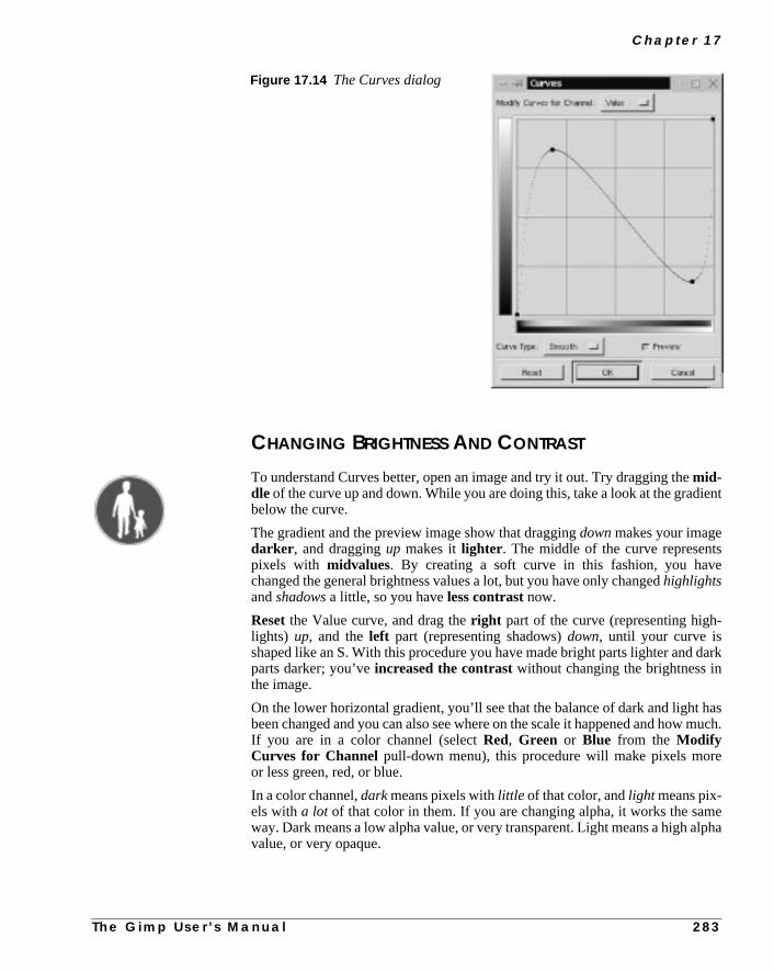
C h a p t e r 1 7
ient
se
-
dark
hasmuch.
e
elpha
CHANGING BRIGHTNESS AND CONTRAST
To understand Curves better, open an image and try it out. Try dragging themid-dle of the curve up and down. While you are doing this, take a look at the gradbelow the curve.
The gradient and the preview image show that draggingdownmakes your imagedarker , and draggingup makes itlighter . The middle of the curve representpixels with midvalues. By creating a soft curve in this fashion, you havchanged the general brightness values a lot, but you have only changedhighlightsandshadows a little, so you haveless contrast now.
Resetthe Value curve, and drag theright part of the curve (representing highlights) up, and theleft part (representing shadows)down, until your curve isshaped like an S. With this procedure you have made bright parts lighter andparts darker; you’veincreased the contrastwithout changing the brightness inthe image.
On the lower horizontal gradient, you’ll see that the balance of dark and lightbeen changed and you can also see where on the scale it happened and howIf you are in a color channel (selectRed, Green or Blue from the ModifyCurves for Channel pull-down menu), this procedure will make pixels moror less green, red, or blue.
In a color channel,darkmeans pixels withlittle of that color, andlight means pix-els witha lot of that color in them. If you are changing alpha, it works the samway. Dark means a low alpha value, or very transparent. Light means a high avalue, or very opaque.
Figure 17.14 The Curves dialog
T h e G i m p U s e r ’ s M a n u a l 2 8 3

I m a g e M e n u : C o l o r s
ftly
ls
youn or
wo
thevee willels
-eent
dffectbject
en.in a
.
ge.
ADJUSTING CURVES
You may have noticed that there is adot at each end of the curve. Drag at one othe dots. You’ll find that the line created to the left or right of the dot is perfecstraight. In practice, this means that dragging theleft dot constrains a range ofdark pixels to the same value, whereas dragging theright dot constrains a rangeof light pixels to the same value. Howlarge this range or interval will be dependson the horizontal length of the line. The darkness or lightness of the pixedepends on where you put the dot on thevertical scale.
Click on different points on the curve. Each click produces another dot, andcan move each dot independently of the others. You can move them up, dowalong the curve. These dots are likeBezier anchor points, but without handles.This means that by moving a dot, you’ll produce a little curve between the tnearest dots. This way you can easily pick a suitablepixel range, and onlychange the values within that range.
To removedots, drag them toward one of the end dots. You can remove all ofdots except one, but if you only have one dot, your curve will be flat. A flat curcauses all values to be the same. If all of the values are the same, your imagturn gray and disappear (or, for example, if you’re in the red channel, all pixwill get the same red value).
The optionCurve Type: Free lets you create or modify your curve with a pencil, which offers unlimited possibilities of fine-tuning colors or values. ThSmoothoption will produce a smoother version of the same curve. Experimwith Curves to learn more.
Unwanted Side EffectsBecause the value is based onRGB, you can sometimes produce an unwantechange in color when you only wanted to change the pixel brightness. This ehappens when you try to make extreme changes, like lightening a very dark owithout disturbing the other colors in the image. If you try to do this, you’llinvertthe color, and you’ll just end up with something red if the object was greInstead of using Curves to produce this effect, you should isolate the objectselection and useright-click|Filters|Colors| Value Invert .This filter works inHSV, and inverts Value without changing Hue or Saturation
LEVELS
Right-click|Image|Colors| Levels is another way of manipulatingRGB properties. Levels is an excellent tool for creatinghighlights or shadowareas, which enhance 3-D effects in your image.
Levels is also useful for adding emphasis to dark or bright areas in the imaWhereasCurvesallows you to manipulate pixels withindefined ranges, Levelsaffect theentire range of pixels. You normally useLevelsfor changing the gen-eral balance between bright and dark parts in the image or selection, andCurveswhen you only want to affect certain color or value ranges.
2 8 4 T h e G i m p U s e r ’ s M a n u a l
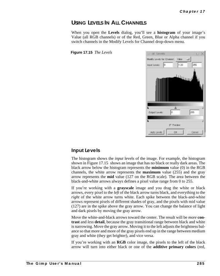
C h a p t e r 1 7
ou
m. The
he
eiteluelight
hiteal-dium
USING LEVELS IN ALL CHANNELS
When you open theLevels dialog, you’ll see ahistogram of your image’sValue (all RGB channels) or of the Red, Green, Blue or Alpha channel if yswitch channels in the Modify Levels for Channel drop-down menu.
Input LevelsThe histogram shows theinput levels of the image. For example, the histograshown in Figure 17.15 shows an image that has no black or really dark areasblack arrow below the histogram represents theminimum value (0) in the RGBchannels, the white arrow represents themaximum value (255) and the grayarrow represents themid value (127 on the RGB scale). The area between tblack-and-white arrows always defines a pixel value range from 0 to 255.
If you’re working with a grayscale image and you drag the white or blackarrows, every pixel to theleft of the black arrow turns black, and everything to thright of the white arrow turns white. Each spike between the black-and-wharrows represent pixels of different shades of gray, and the pixels with mid va(127) are in the spike above the gray arrow. You can change the balance ofand dark pixels by moving the gray arrow.
Move the white-and-black arrows toward the center. The result will bemorecon-trast andlessdetail, because the gray transitional range between black and wis narrowing. Move the gray arrow. Moving it to the left adjusts the brightness bance so that more and more of the gray pixels end up in the range between megray and white (they get brighter), and vice versa.
If you’re working with anRGB color image, the pixels to the left of the blackarrow will turn into either black or one of theadditive primary colors (red,
Figure 17.15 The Levels
T h e G i m p U s e r ’ s M a n u a l 2 8 5
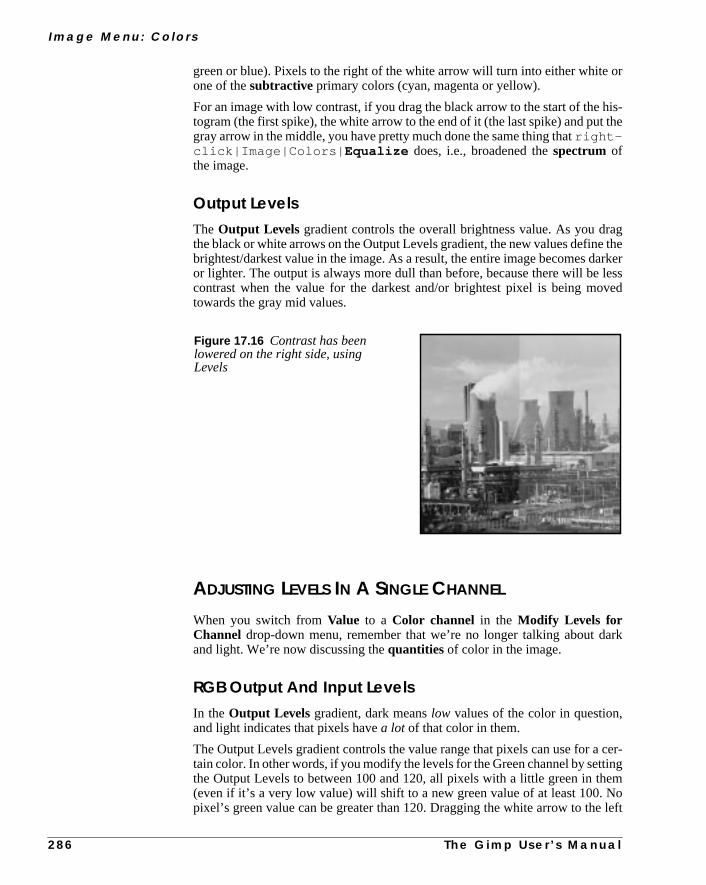
I m a g e M e n u : C o l o r s
or
is-the
agthe
arkerlessved
ark
cer-ingemoleft
green or blue). Pixels to the right of the white arrow will turn into either whiteone of thesubtractive primary colors (cyan, magenta or yellow).
For an image with low contrast, if you drag the black arrow to the start of the htogram (the first spike), the white arrow to the end of it (the last spike) and putgray arrow in the middle, you have pretty much done the same thing thatright-click|Image|Colors| Equalize does, i.e., broadened thespectrum ofthe image.
Output LevelsThe Output Levels gradient controls the overall brightness value. As you drthe black or white arrows on the Output Levels gradient, the new values definebrightest/darkest value in the image. As a result, the entire image becomes dor lighter. The output is always more dull than before, because there will becontrast when the value for the darkest and/or brightest pixel is being motowards the gray mid values.
ADJUSTING LEVELS IN A SINGLE CHANNEL
When you switch fromValue to a Color channel in the Modify Levels forChannel drop-down menu, remember that we’re no longer talking about dand light. We’re now discussing thequantities of color in the image.
RGB Output And Input LevelsIn the Output Levels gradient, dark meanslow values of the color in question,and light indicates that pixels have a lot of that color in them.
The Output Levels gradient controls the value range that pixels can use for atain color. In other words, if you modify the levels for the Green channel by settthe Output Levels to between 100 and 120, all pixels with a little green in th(even if it’s a very low value) will shift to a new green value of at least 100. Npixel’s green value can be greater than 120. Dragging the white arrow to the
Figure 17.16 Contrast has beenlowered on the right side, usingLevels
2 8 6 T h e G i m p U s e r ’ s M a n u a l

C h a p t e r 1 7
n you
nd
rentes of
ple:
d
ted,
causes the image to have less green (i.e., more red). The opposite is true whedrag the black arrow to the right.
The result of moving theInput Levels arrows in a color channel isn’t as obviousas withValue. The result depends on how much of the color is in the image, ain what range most of the color is found.
Levels And Alpha ChannelsThe alpha channel works the same way as RGB: Dark meanslow alpha (or trans-parent) and white ishigh alpha (fully opaque).
Modify Levels for the alpha channel on feathered or otherwise semi-transpaselections or layers, i.e., on areas with great variation in alpha values. Examplthis are selections created from analpha mask channelor layers where youhave applied aLayer mask.
EXAMPLE: MAKING CARVED TEXT WITH LEVELS
To help you understand what you can do with Levels, work through this exam
1. Create a new image with a white background. With the commandFile|New, chooseFill Type White (you can just leave the Fill Type atBackground if the background color in the toolbox is set to white).
2. Create a white layer in this image. Use the commandright-click|Layers| Layers & Channels to open the Layers & Channels dialog.Click on theNew Layer button. In the New Layer Options dialog, click onLayer Fill Type White and click OK.
3. Click on theBackground in the Layer & Channels dialog, so you’re workingin the background layer. Choose theText tool and write a few (black, notgray or colored) letters on the white background. In this example we usewhite text on a black oval. You may have to click “off” theeye icon on thenew layer so that you can see the background. With the letters still selecapply someright-click|Filters|Blur| Gaussian Blur .The more blur you apply, the more bevel and softness you’ll get in thebumpmap image you’ll create next.
Figure 17.17 White letters before and after Gaussian blur
T h e G i m p U s e r ’ s M a n u a l 2 8 7

I m a g e M e n u : C o l o r s
e
of
of
4. Activate the white layer (click on it in theLayers & Channels dialog, andclick “on” theeye icon so you can see the white layer). Selectright-click|Filters|Map| Bump Map.
5. Choose the background layer of your image from theBump map pull-downmenu and click OK.
6. You should now have a nice3-D image of the letters in your layer. UseGaussian blur if you think the shadows are too hard, andDuplicate the 3-Dlayer. One of these bumpmapped layers will be the highlight layer and thother will be the shadow layer.
7. Activate the top layer and openright-click|Image|Colors|Levels . Move theblack andgray arrows below theInput Levelsgradient to the right, until you see the bright highlights of the letters on topa black background. Click OK.
8. Activate the middle layer, and open the Levels dialog again. Move thewhiteandgray Input Levels arrows to the left, until you see the shadows on topa white background. Click OK.
9. Click on thehighlight layer. SelectScreen from theMode pull-down menuto change the mode of the highlight layer to Screen.
Figure 17.19 The newlybumpmapped image
Figure 17.20 Thehighlight layer
Figure 17.21 Shadowlayer
Figure 17.22 The finishedimage
2 8 8
T h e G i m p U s e r ’ s M a n u a l
C h a p t e r 1 7
m-e byility
ere
arly
achr to
10. Change the mode of theshadow layer toMultiply .
11. Fill the background with a suitable color or pattern using theBucket Filltool.
DESATURATE
Right-click|Image|Colors| Desaturate removes color from alayer or selection without disturbing the rest of the composite image. This comand is useful when you want to put emphasis on a certain object in an imagdraining the color from everything else. This option also gives you the possibto work with grayscale in certain layers, and with color in others.Desaturatedoes not turn your image into a grayscale. Your image is still RGB, even if this no visible color.
AUTO-STRETCH CONTRAST
Right-click|Image|Colors| Auto-Stretch Contrast worksjust like Auto-Stretch HSV, but within RGB color space. This command iswonderful image enhancer. It is great for removing undesired color tints in poodeveloped or aging photos.
AUTO-STRETCH HSVRight-click|Image|Colors| Auto-Stretch HSV makes an auto-matic contrast stretch of your image. It finds the lowest and highest values of eHSV channel and stretches them to the full contrast range. This is similaAuto-Stretch Contrast, but Auto-Stretch Contrast works with RGB values.
Figure 17.23 Theright side wascorrected with Auto-Stretch Contrast
T h e G i m p U s e r ’ s M a n u a l 2 8 9

I m a g e M e n u : C o l o r s
st
toage
Auto-Stretch HSV is a great filter for enhancing or correcting old pictures. Teit on some old, faded images. If that doesn’t work, tryright-click|Image|Colors| Equalize .
NORMALIZE
Right-click|Image|Colors| Normalize is similar to Auto-Stretch Contrast, but it won’t allow the RGB channels to stretchindepen-dently. Instead, they are treated as aunion. Technically, the difference is thatwith Normalize, all of the channels will not stretch over the whole range from 0255, so just the highest values go to the edges. This filter is an excellent imenhancer for scanned images.
Figure 17.24 Theright side was correctedwith Auto-Stretch HSV
Figure 17.25 The rightside was corrected withNormalize
2 9 0 T h e G i m p U s e r ’ s M a n u a l

C h a p t e r 1 7
ed
lp
tool
e (or
COLORCUBE ANALYSIS
Right-click|Image|Colors| Colorcube Analysis is a greattool for indexing, since it informs you of the compressed and uncompresssizes, dimensions and the number of unique colors in an image.
If you’re working on a GIF image (which is already indexed), this tool will heyou keep track of the image size as you bring down the number of colors.
If you’re preparing an RGB or grayscale image for indexing, you can use thisafter running theright-click|Filters|Colors| Quantize filter onchosen selections to keep informed on the total number of colors in the imagbefore running it to determine the number of colors in the selection).
T h e G i m p U s e r ’ s M a n u a l 2 9 1
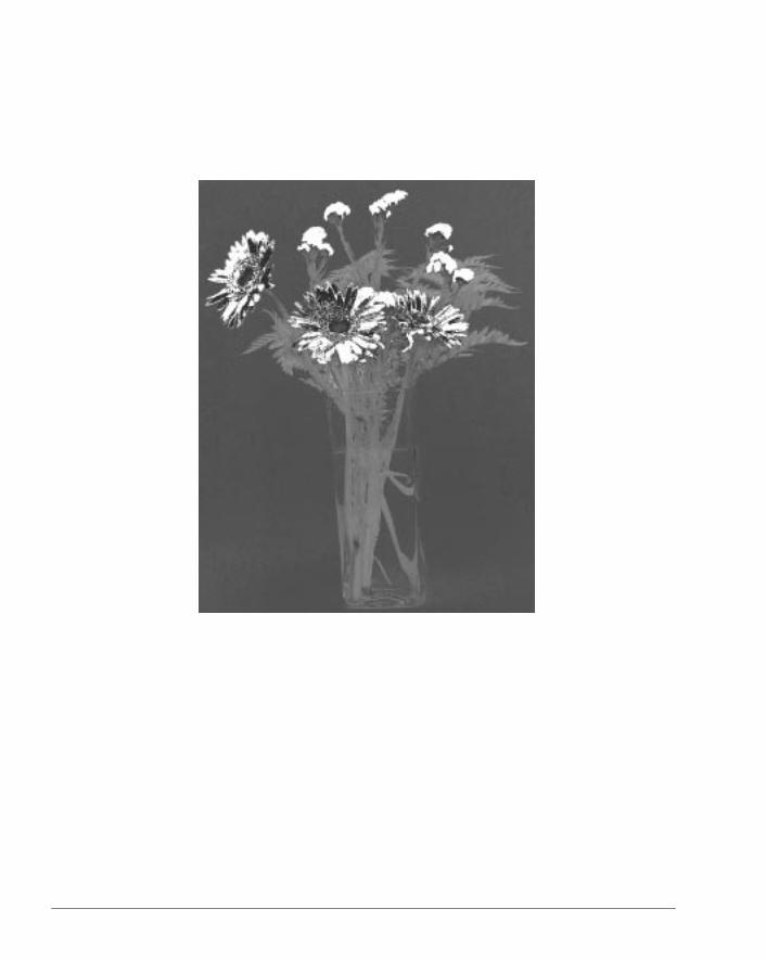

C H A P T E R
18 Image Menu: Channel Ops And AlphaThe Image menu offers some of the most usefulimage manipulating functions in Gimp. In thischapter, we’re going to discuss what you can dowith Channel Ops and Alpha in the Image menu.

I m a g e M e n u : C h a n n e l O p s A n d A l p h a
ivenneluse-
ated.nd
used
e
hesidethe
it.
THE CHANNEL OPS MENU
The right-click|Image| Channel Ops commands were once the onlyway of handling composite image information. Now that Gimp supports effectlayer handling, the few commands in this menu are all that remain of the chaoptions. Nevertheless, the items in this menu contain some very powerful andful features.
DUPLICATE
Right-click|Image|Channel Ops| Duplicate copiesall layers andchannels in a composite image, so that a complete replica of your image is creBe sure to use it every time you want to experiment with different solutions avariations on an image.
OFFSET
Right-click|Image|Channel Ops| Offset , which tiles and rearrangesthe edge pixels in your image, only affects the active layer/channel. It can beto place layers or floating selections to a specific position in the image.
Offset is useful if you want to move layers a very exact amount, or if you’d likto move them without extending thelayer border. The other important applica-tion of this command is to createseamless tilesfor patterns.
If the Wrap-Around button is checked, after you offset the layer or selection, tparts of the image that moved outside the layer border will turn up on the otherof the image. If you don’t want this, you can choose to fill the empty area withbackground color or withtransparency.
Using Offset To Adjust Pattern TilesOffset allows you to makeseamless tiles. If you want to make a wallpaper patternof your image, it’s a good idea to check how well the edges fit, before you tile
Figure 18.1 The Offset dialog
2 9 4 T h e G i m p U s e r ’ s M a n u a l

C h a p t e r 1 8
e tiles.e is.
rs.
that
ithy-
If you click on the Offset by (x/2),(y/2) button with the Wrap-Aroundcheckbox checked, you’ll split your image intofour equal tiles.
To create a seamless tile, you need to erase the sharp borders between thThere are many ways of doing this, depending on how complicated the imagYou can use theClone tool and theTransform tool; you canPaint, Copy andPaste suitable selections with different opacities; or you can use special filte
When you’re satisfied with the results, click on theOffset by (x/2),(y/2) but-ton again, and your image will return to normal, but now with seamless edgeswill produce a perfect result when tiling the image.
The right-click|Filters|Map| Make Seamless filter also pro-duces seamless tiles. Tiling looks very good with this filter. The problem wMake Seamlessis that you can never get really sharp patterns with it. Everthing looks a bit blurred and double-exposed.
You can also try theright-click|Filters|Blur| Tileable Blurfilter, which creates softer, if not entirely seamless, edges.
Original Tiled
Offset and Tiled Make Seamless and Tiled
Figure 18.2 Here, you can appreciate the difference between usingTiled, Offset and Tiled and Make Seamless and Tiled
T h e G i m p U s e r ’ s M a n u a l 2 9 5

I m a g e M e n u : C h a n n e l O p s A n d A l p h a
eate
Correcting TilesFollow this example to get an idea of how the Offset tool can be used to crseamless pattern tiles.
Figure 18.3 This is a nicepicture of a brick pavement. I’dlike to use this image to make apattern.
Figure 18.4 I apply the SmallTiles filter to get a preview ofwhat a pattern would look likeusing this image. Sorry to say, itdoesn’t look very convincingwhen I tile it.
Figure 18.5 When I use Offsetby (x/2),(y/2) on my image, it’sclear that the tiles don’t matchvery well
2 9 6
T h e G i m p U s e r ’ s M a n u a l
C h a p t e r 1 8
-
els,
COMPOSE AND DECOMPOSE
Right-click|Image|Channel Ops| Composemerges at least three grayscale images into one color image.Decomposeis a way ofextracting chan-nels from an image. You can break up your image into its constituent channby extracting RGB, HSV, CMY(K) or alpha information.
Figure 18.6 Now I’vemanipulated the offset image bycopying and pasting bricks intopositions that will erase thesharp borders. I used the Clonetool to smooth edges, the Painttool to make the colors blend andthe Rotate Transform tool tomake the pasted selections fit thepattern. This time it looks muchbetter!
Figure 18.7 When I’msatisfied with the Offset adjustedimage, I can rest assured that thepattern rendered from this imagewill look alright
Figure 18.8 The Decompose dialog
T h e G i m p U s e r ’ s M
a n u a l 2 9 7
I m a g e M e n u : C h a n n e l O p s A n d A l p h a
f-. The
ec-
o anact
om-
RGB DecomposingDecomposing to RGB is the same as activating a color channel in theLayers &Channelsdialog, but now you’ll get the color channels in the form of three diferent grayscale images. You can do a lot of things with decomposed imagesfirst thing that comes to mind is to edit them in different ways, and then useCom-pose to put them together again.
This option lets you manipulate color channels in ways that theChannels tabfolder does not allow. If youdecomposeyour image, there is, for example, noproblem in performing operations like cutting/copying/pasting, or moving seltions in a single RGB channel.
You can use an extracteddecomposedgrayscale as aselectionor mask by sav-ing it in a channel (right-click|Select| Save to Channel ).Sometimes, there is very little of a certain color in the background compared tobject in the image. This gives you the perfect opportunity to create very exselections of intricate objects. You can also play around with Compose/Decpose to create interesting patterns.
Figure 18.9 The Compose dialog
2 9 8 T h e G i m p U s e r ’ s M a n u a l
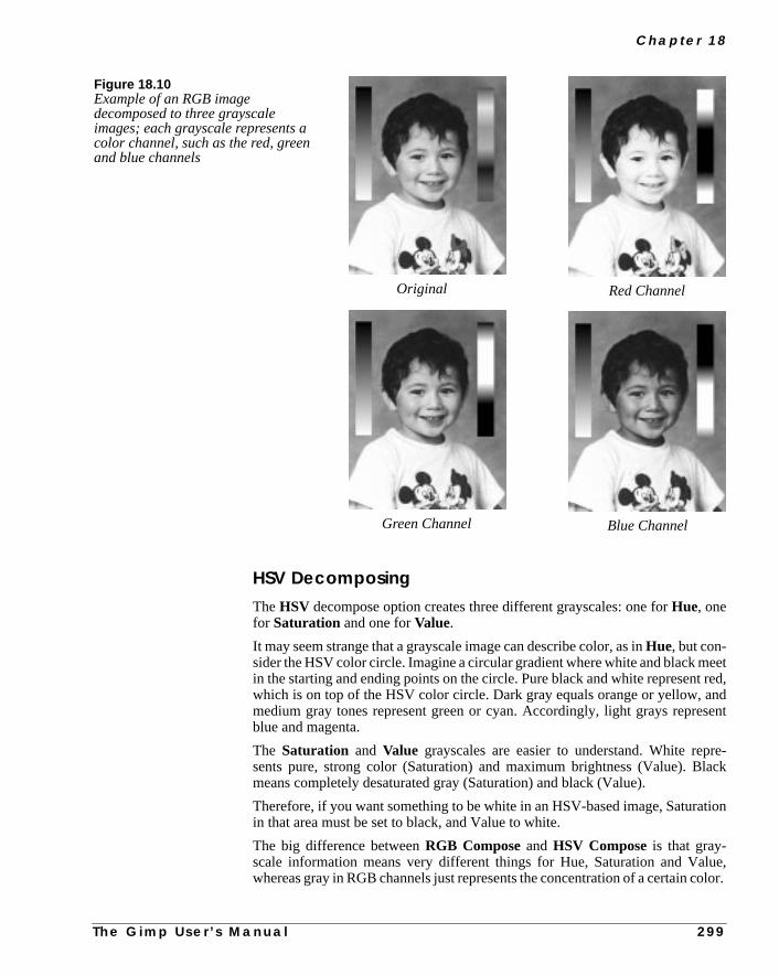
C h a p t e r 1 8
eett red,ndsent
re-lack
tion
lue,olor.
HSV DecomposingTheHSV decompose option creates three different grayscales: one forHue, onefor Saturation and one forValue.
It may seem strange that a grayscale image can describe color, as inHue, but con-sider the HSV color circle. Imagine a circular gradient where white and black min the starting and ending points on the circle. Pure black and white represenwhich is on top of the HSV color circle. Dark gray equals orange or yellow, amedium gray tones represent green or cyan. Accordingly, light grays repreblue and magenta.
The Saturation and Value grayscales are easier to understand. White repsents pure, strong color (Saturation) and maximum brightness (Value). Bmeans completely desaturated gray (Saturation) and black (Value).
Therefore, if you want something to be white in an HSV-based image, Saturain that area must be set to black, and Value to white.
The big difference betweenRGB Composeand HSV Composeis that gray-scale information means very different things for Hue, Saturation and Vawhereas gray in RGB channels just represents the concentration of a certain c
Original Red Channel
Blue ChannelGreen Channel
Figure 18.10Example of an RGB imagedecomposed to three grayscaleimages; each grayscale represents acolor channel, such as the red, greenand blue channels
T h e G i m p U s e r ’ s M a n u a l 2 9 9

I m a g e M e n u : C h a n n e l O p s A n d A l p h a
youB,ame
vee of
This also explains why it is possible to manage with just one grayscale, whenarecomposingto HSV. If you were to use the same grayscale for composing RGthe result would be exactly the same as the original grayscale. If you did the sfor CMYK, you’d just end up with an overbright negative of the image.
To show the great difference between the HSV-extracted grayscales, we hadecomposed an image to HSV and composed it again using Value in the placHue, and vice versa. See Figure 18.11, below.
Hue Saturation
Value Value composed as Hue
Figure 18.11 The same RGBimage, but decomposed in HSVspace
3 0 0 T h e G i m p U s e r ’ s M a n u a l
C h a p t e r 1 8
atated)
ara-se
fes-terting
for
yer
ell asThis
d a
CMYK And CMY DecomposingThe CMY or CMYK Decompose options are interesting if you are planningto print your work. The difference between CMY and CMYK decomposing is thCMY doesn’t decompose to black, and therefore creates darker (more saturgrayscale separations.
Using CMYK Decompose is actually the same as making your own color seption for four-color printing plates (see Figure 18.12). In principle, you can uCMYK Decompose, print the outcome on a laser printer, and give it to a prosional print shop, but the professional printer will most likely do a much betseparating job than you can. However, you can certainly achieve very interesresults with CMY/CMYK decomposed images, even if you don’t use themprinting purposes.
Alpha DecomposingAlpha Decomposeis a fast and easy way of converting a semi-transparent lato an equivalent grayscale. You can accomplish the same effect by using aLayerMask, but Compose/Decompose lets you decompose a layer to alpha as wto RGB, and then compose a new RGBA image from the edited grayscales.allows you to edit all channel information, not just transparency.
It’s a very convenient way to edit layers with transparency information, anworthwhile alternative to editing using commands from theLayers & Chan-nelsmenu.
T h e G i m p U s e r ’ s M a n u a l 3 0 1

I m a g e M e n u : C h a n n e l O p s A n d A l p h a
C M
Y K
Printout of CPrintout of M
Printout of YPrintout of K
Figure 18.12 The same RGBimage decomposed to CMYK; thefour images at the bottom show whatthe outcome of each process platewould look like if it was printed onpaper
3 0 2 T h e G i m p U s e r ’ s M a n u a l

C h a p t e r 1 8
the
t-g
-red
.
pof
mi-fty
ALPHA
ADD ALPHA CHANNEL
If you wish to add alpha information (be able to work with transparency) tobackground layer, you can use this option.Add Alpha Channel is also avail-able in theright-click|Layers menu and in the menu you get when righclicking in theLayers & Channelsdialog. See “Channels And Duotones” startinon page 351 for more information on alpha channels.
HOLES
This command requires alayered image. As you may have noticed, indexedimages like GIFdon’t supportsemi-transparency. Holes creates a rather convincing illusion of semi-transparent pixels (at least if you compare it to a ditheNetscape image in 8 bit mode).
You can, of course, useDissolveto achieve a similar effect, but this is slickerIn order to make this look good, you must use a smallHole Size(like 1) and amedium to low Density (like -1.50).
Make sure theKeep Opaque checkbox is checked. If you don’t use KeeOpaque, you’ll risk getting spillout or “dot pollution” on the transparent areasthe image. This is undesirable behavior if you’re trying to create a setransparent look in a GIF, but if you’re not, this option can result in quite nieffects.
Depending on what effect you want, you can change theshapeandsizeof theholes. You can choose fromsquare, round anddiamond, though round- anddiamond-shaped holes require a minimum size of 2.
Figure 18.13 The Holesdialog
T h e G i m p U s e r ’ s M a n u a l 3 0 3

I m a g e M e n u : C h a n n e l O p s A n d A l p h a
mi-t yous youues
THRESHOLD ALPHA
The right-click|Image|Alpha| Threshold Alpha filter onlyworks for images which contain an alpha channel. SelectAdd Alpha Channelfrom the same menu to enable transparency.
Threshold Alpha lets you remove pixels by theiralpha value or transparency.The resulting image is always totally transparent or solid and never setransparent, so it’s a great tool for controlling the appearance of an image thawant to save as a transparent GIF. The slider value determines which valuewant to remove. If you set a high value, only pixels with even higher alpha val(less transparent pixels) will remain after the filter is applied.
Figure 18.14 A semi-transparent image converted toGIF with and without Holes
Original Without Holes With Holes
3 0 4 T h e G i m p U s e r ’ s M a n u a l


C H A P T E R
19 Select MenuHere, we will explore how Gimp allows you to makeadvanced selections using the commands in theSelect menu.

S e l e c t M e n u
,
cts.nts willg”
fthers),
ans.
, butt.
to
heo aore
CREATING SELECTIONS
TOGGLE
Right-click|Select| Toggle allows you to turn the “marching ants”border around layers and selectionsonoroff. This border is sometimes distractingand prevents you from seeing what you are doing, so this is a nice option.
INVERT
Use right-click|Select| Invert to select everythingexceptyour cur-rent selection — usually the background or surroundings of selected objeSelect what youdon’t want to include, then click on Invert to unselect the curreselection and select the remainder of the image. Note that feathered selectionstill be feathered when inverted, but the feathering will now do the “fuzzyininwards, toward the object border.
ALL AND NONE
Right-click|Select| All selects everything in your image or layer. Iyou have several objects in a transparent layer and want to fill all of them atsame time (most commonly a text layer, where you want to select all of the letteuse Select All with the Keep Trans. checkbox on theLayers & Channelsdialog checked.
You may also want to use this command to select an entire layer (with Keep Trunchecked) if you want to fill all of it with paint and discard the objects in it.
Right-click|Select| None unselects everything. You could just click onthe layer with the rectangular or ellipse selection tools to get the same resultif you drag the tool while doing this, you will transform the selection to a floaThis option is quicker and safer.
FLOAT
Use right-click|Select| Float when you want your selection tofloat, but not tomove. As previously discussed, you can transform a selectiona float by moving it when the Select tool is still active.
Moving it like this will change the position of the selection, at least a little bit. Teffect will be even more obvious if you took the float from the background, s“hole” now exists in the background image where the float used to be. Read mabout floating selections in “Channels And Duotones” starting on page 351.
3 0 8 T h e G i m p U s e r ’ s M a n u a l

C h a p t e r 1 9
rhapst to
ction
eov-
ke
thein the
er is.re fill-
nntil itage
y.sual.canese
st).
ADJUSTING SELECTIONS
SHARPEN
Right-click|Select| Sharpen removes thefuzzinesson the edges of afeathered selection, leaving a sharp-edged core.Sharpenwill not restore any edgedetail to a feathered selection, however.
Use Sharpen when you change your mind about feathering a selection. Pemore commonly, use Sharpen when you have added a fuzzy fill and wanenhance it by making a sharp fill or paste inside of the fuzzy one (a sharp seleis always smaller than a fuzzy selection).
BORDER
Right-click|Select| Border creates a new selection surrounding thoutline of the old one. The new selection is a hollow border area or frame that cers an area both outside and inside the original selection edge.
Border is useful for applying special effects to text, or when you want to madrawings or frames from selections.
The Difference Between Border And StrokeThe effects ofright-click|Edit| Stroke may seem similar to applyingBorder and filling the new selection. However, the Stroke outline is based onshape, size, fuzziness and other parameters of the currently selected brushbrush dialog.
A Border selection has fuzzy edges by default, the more so the wider the bordThis means that you may sometimes have to use Sharpen on the border befoing it, to remove unwanted blur effects.
FEATHER
Right-click|Select| Feather produces a selection with fuzzy edges. Iother words, a feathered selection becomes more and more transparent ureaches the edges of the selection. Feather allows you to blend a color or imsoftly with the background.
On theFeather dialogyou select how much you want to feather the selection bA low value produces a selection with a bit more softness to the edge than uThe maximum value produces a very fuzzy selection; it will be so soft that youfill it with patterns, then with colors, and then paste images into it, and all ththings will blend together. If theKeep Trans.checkbox on theLayers & Chan-nelsdialog is checked, filling or painting within the selection will only affect areathat have an alpha value greater than zero (i.e., that are not fully transparen
T h e G i m p U s e r ’ s M a n u a l 3 0 9

S e l e c t M e n u
ittou’d-
dk or
me,
v-rencynelctionuo-
gon
Feathering reduces thedetail of the selection’s shape.Edge detaildisappears ina fuzzy fog, and a hand-shaped selection with fingers will look like a softball mat best. You can use this to your advantage if your selection isn’t as smooth as ylike. UseFeather to smooth, useGrow to make the selection a little bigger (compensating for the loss in size from feathering), and lastly useSharpen.
GROW AND SHRINK
Grow andShrink allow you to modify the size of the selection by a specifieamount. If the selection edge has fine details, they will disappear if you shringrow too much.
If you want your selection to be bigger or smaller, but otherwise look the sayou should instead save the selection to a layer and apply theScale Layercom-mand from the menu you get by right-clicking in theright-click|Layers|Layers & Channels dialog.
SPECIAL SELECTION COMMANDS
SAVE TO CHANNEL
If you are working with a complicated image, you should useright-click|Select| Save To Channel almost every time you make a selection. By saing the selection as a channel, you’re storing the selection’s shape and transpain analpha channel. After saving it as a channel, you can later activate the chanand use the selection again if you need it. You can also do very advanced seleediting using alpha channels. For more information, read “Channels And Dtones” starting on page 351.
BY COLOR
Select By Color is a very advanced tool. You can use it to modify an existinselection, or you can create entirely new selections with it. This tool is basedcolor, but it works fine for grayscale or indexed images.
Click on By Color to display theBy Color Selectiondialog. Click on an areain your image. All pixels with that color or a similar color will be selected.
3 1 0 T h e G i m p U s e r ’ s M a n u a l
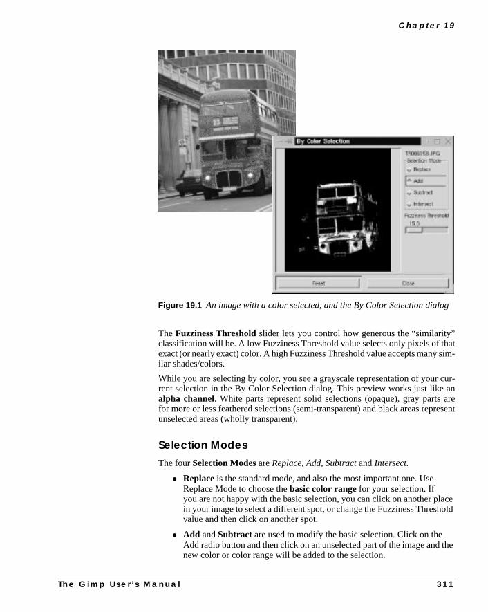
C h a p t e r 1 9
”hatsim-
cur-anareresent
ceold
the
g
TheFuzziness Thresholdslider lets you control how generous the “similarityclassification will be. A low Fuzziness Threshold value selects only pixels of texact (or nearly exact) color. A high Fuzziness Threshold value accepts manyilar shades/colors.
While you are selecting by color, you see a grayscale representation of yourrent selection in the By Color Selection dialog. This preview works just likealpha channel. White parts represent solid selections (opaque), gray partsfor more or less feathered selections (semi-transparent) and black areas repunselected areas (wholly transparent).
Selection ModesThe fourSelection Modes areReplace, Add, Subtractand Intersect.
• Replace is the standard mode, and also the most important one. UseReplace Mode to choose thebasic color range for your selection. Ifyou are not happy with the basic selection, you can click on another plain your image to select a different spot, or change the Fuzziness Threshvalue and then click on another spot.
• Add andSubtract are used to modify the basic selection. Click on theAdd radio button and then click on an unselected part of the image andnew color or color range will be added to the selection.
Figure 19.1 An image with a color selected, and the By Color Selection dialo
T h e G i m p U s e r ’ s M a n u a l 3 1 1

S e l e c t M e n u
to
ttt
eeful
ent
c-
wns
ting.
ge,e
• Subtract will deselect areas of unwanted color from your selection.Click on the Subtract radio button and then click on areas in your imageremove them from the selection.
• Intersect is a little trickier to understand. Intersect chooses areas ofintermediate color between the original selection color and an adjacencolor that you click on. If you click on a color that isn’t directly adjacento the original selection in the image, you’ll end up with no selection aall. Using Intersect usually results in selecting thin, antialiased edgesbetween different shapes.
OptionsWhen you’re using select By Color, you can see itsTool Options dialog byclicking onFile|Dialogs| Tool Options .
If you click on theSample Mergedoption, you base the color selection on thentire composite image instead of just the colors in the active layer. This is usif the active layer is slightly transparent or has another layer mode thanNormal.Then, the colors of the composite image will be different than the colors presin the active layer.
The Antialiasing checkbox is checked by default. If you uncheck it, the seletion will become sharp with absolutely no feathering.
The Feather option is quite interesting. Watch the selection preview windoclosely when you select with this option. You’ll create soft cloudlike selectiowith Replace, and lightning or metal highlight effects withIntersect. Feel free toexperiment with the Feather option checked. The results are always interes
If you like the grayscale selection preview and want to work with it as an imayou can save it using theSave To Channelcommand, and then copy and pastthat channel to a layer.
Figure 19.2 The By Color Selection options dialog
3 1 2 T h e G i m p U s e r ’ s M a n u a l


C H A P T E R
20 Layers And Floating SelectionsLayers and the use of layers are the foundation ofeffective image manipulation.

L a ye r s A n d F l o a t i n g S e l e c t i o n s
s thenlec-es ofed. It
withe it
INTRODUCTION
If you’re new to image manipulation, the con-cept of layers may not seem obvious, butusing layers is really as simple and straight-forward as wearing layers of clothes on yourbody. Once you have started to use layers, youwon’t understand how you could ever dowithout them.
COMPOSITE IMAGE
INFORMATION
An image created or manipulated in Gimpusually consists of several image objects.You may, for instance, have copied andpasted parts of other images into your image,or perhaps you have added a text string.Instead of placing all of these things onto asingle background, you can paste or paintthem in different layers.
These layers are just like a stack of transpar-ent plastic sheets placed on top of oneanother, creating acomposite image. Thismeans that you can easily manipulate the con-tents of a certain layer without affecting therest of the image. You also have artistic free-dom with the possibility to adjust the trans-parency in a layer, or to composite it withother layers usingLayer Modes.
OPTIMAL LAYER SIZE
Contrary to other graphics programs where all layers have the same size aimage, Gimp has the ability tooptimize the layer size. When you turn a selectio(for example, a text string) into a layer, the new layer is never larger than the setion itself. This saves both disk space and valuable processing time. The edgthe small layers appear as a yellow dotted line, and can easily be distinguishis also a great advantage to be able to move an entire layer and its contentstheMove tool, instead of first having to select the image object and then movwithin the layer.
Figure 20.1 The Layersdialog
3 1 6 T h e G i m p U s e r ’ s M a n u a l

C h a p t e r 2 0
d
enu
e one
a
ew
yerer.se
THE LAYERS & CHANNELS DIALOG
Open the Layers & Channels dialog (right-click|Dialogs| Layers &Channels or right-click|Layers| Layers & Channels ). Thereare two tabs:LayersandChannels. Channels will be discussed in “Channels AnDuotones” starting on page 351.
The Layers TabThe Layers tab includesImage andMode pull-down menus, anOpacity sliderand aKeep Trans.(Keep Transparent) checkbox.
TheImagepull-down menu is at the top of the dialog, and will display the namof your image. If you are working with several images, the Image pull-down meis very useful, because all open images are listed in it and you can choose thyou want to work with by clicking on its name.
Six buttons are at the bottom of the dialog:New Layer, Raise Layer, LowerLayer, Duplicate Layer, Delete Layer and Anchor floating selection. All ofthese buttons will be discussed later in this chapter.
Each layer has abar corresponding to it in the dialog window. The bar containsthumbnail icon of the layer. Aneye iconis to the left of the thumbnail, and ifyour image only contains one layer, your image/layer will be calledBackground.
BASIC LAYER OPERATIONS
NEW LAYER
If you right-click on a layer’s bar, another menu will appear that includes a fmore options than theright-click| Layers menu. Choose the first optionon the list —New Layer —or click the left toolbar button.
When you choose New Layer, theNew Layer Options dialog will appear.Name your layer in the Layer name box. For example, you could call the la“shadow” if you are going to create a shadow of an image object in this layAlways name your layers if you work with a lot of them, especially when you usimilar layers with different functions.
Figure 20.2 The New Layer Optionsdialog
T h e G i m p U s e r ’ s M a n u a l 3 1 7

L a ye r s A n d F l o a t i n g S e l e c t i o n s
can
ll.,
theare
er’sill
by
keytheit’sol”
Theerrksartsface.
(forande
If you don’t want the new layer to be the same size as the background, youspecify the size of the layer by filling values into theLayer width andLayerheight boxes.
You also need to decide on aLayer Fill Type . Your options areBackground(the current background color in the toolbox),White, Transparent andFore-ground (the current foreground color in the toolbox). White is the default fiClick on the radio button for the fill you want and click on the OK button. Nowyou have created a new layer on top of your background.
THE ACTIVE LAYER
When you have two ore more layers, it’s really important to know which one isactive layer. As soon as you have several layers in an image, Gimp’s actionsin the active layer, so you can only work in one layer at a time. The active laybar in the dialog is marked with blue. If you click on another layer’s bar, it wbecome the active layer.
If a layer is smaller than the background layer, you can also make it activeclicking in it (in the image) with theMove tool. If you want to move atrans-parent layer, or just make sure that you move the right layer, press the Shiftas you drag. With the Shift key pressed, only the active layer will move. Whenselected layer’s boundary changes color from yellow to blue, you know thatsafe to move it. For more information about the Move tool, see “The Move Toon page 156.
THE BACKGROUND LAYER
Remember that your original image was automatically named Background?background layer doesn’t act exactly like other layers. The background layis a fixed and solid area for other layers to work against. The background wothe same way that it did when you didn’t have any other layers. When you cut pof it, or use the eraser, the background color shows, and not a transparent sur
You also can’t useLayer masks (see “Add Layer Mask” on page 322) on thebackground layer, and you can’traise the background layer. Normally, you won’tneed to do any of these things with a background layer, but if you want totransparent GIFs, for example), double-click on the background layer’s bar,rename it. From then on, it will act like any other layer. To achieve the samresult, you could also useright-click|Layers| Add Alpha Chan-nel , or duplicate the background, keep the copy and delete the original.
3 1 8 T h e G i m p U s e r ’ s M a n u a l
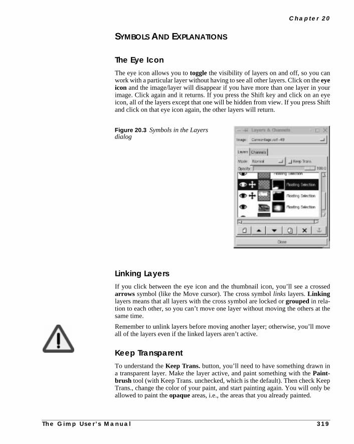
C h a p t e r 2 0
oureyeift
sed
the
ove
n
epbe
SYMBOLS AND EXPLANATIONS
The Eye IconThe eye icon allows you totoggle the visibility of layers on and off, so you canwork with a particular layer without having to see all other layers. Click on theeyeicon and the image/layer will disappear if you have more than one layer in yimage. Click again and it returns. If you press the Shift key and click on anicon, all of the layers except that one will be hidden from view. If you press Shand click on that eye icon again, the other layers will return.
Linking LayersIf you click between the eye icon and the thumbnail icon, you’ll see a crosarrows symbol (like the Move cursor). The cross symbollinks layers.Linkinglayers means that all layers with the cross symbol are locked orgrouped in rela-tion to each other, so you can’t move one layer without moving the others atsame time.
Remember to unlink layers before moving another layer; otherwise, you’ll mall of the layers even if the linked layers aren’t active.
Keep TransparentTo understand theKeep Trans. button, you’ll need to have something drawn ia transparent layer. Make the layer active, and paint something with thePaint-brush tool (with Keep Trans. unchecked, which is the default). Then check KeTrans., change the color of your paint, and start painting again. You will onlyallowed to paint theopaqueareas, i.e., the areas that you already painted.
Figure 20.3 Symbols in the Layersdialog
T h e G i m p U s e r ’ s M a n u a l 3 1 9

L a ye r s A n d F l o a t i n g S e l e c t i o n s
It alsoave toer,. isent
7.
hy.an’t
l.
tion
Keep Trans. protects the boundaries of opaque shapes in a transparent layer.makes it very easy to change opaque shapes’ colors, because you never hworry about painting outside of their edges. If you want to use a filter on a layyou normally won’t want to have this option checked, because if Keep Transchecked, the filter will only affect the interior of opaque objects in the transparlayer.
NamingYou canrename a layer by double-clicking on the layer’s old name. TheEditLayer Attributes dialog will allow you to type in a new name.
THE LAYER TOOLBAR BUTTONS
New LayerCreates a new layer, as described in the paragraph “New Layer” on page 31
Raise Layer And Lower LayerThese commands (and the corresponding buttons on theLayers & Channelsdialog) move the active layer to a higher or lower position in the layer hierarcYou can only raise or lower a layer one step at a time. The background layer cbe raised, unless yourename it or applyAdd Alpha Channel (see “Add AlphaChannel” on page 325).
Duplicate LayerMakes acopyof the active layer, and places it immediately above the origina
Delete LayerDeletes the active layer.
Anchor LayerAnchor Layer is used tomerge floating selections with a layer (the layer thawas active before you placed the float). If you don’t know what a floating selectis, read “Floating Selections” on page 331.
Figure 20.4 The Edit Layer Attributes dialog
3 2 0 T h e G i m p U s e r ’ s M a n u a l
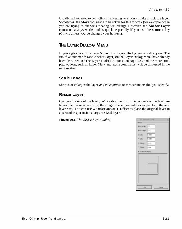
C h a p t e r 2 0
er.n
key
dyom-
n the
new
Usually, all you need to do is click in a floating selection to make it stick to a laySometimes, theMove tool needs to be active for this to work (for example, wheyou are trying to anchor a floating text string). However, theAnchor Layercommand always works and is quick, especially if you use the shortcut(Ctrl+h, unless you’ve changed your hotkeys).
THE LAYER DIALOG MENU
If you right-click on a layer’s bar, the Layer Dialog menu will appear. Thefirst five commands (and Anchor Layer) on the Layer Dialog Menu have alreabeen discussed in “The Layer Toolbar Buttons” on page 320, and the more cplex options, such as Layer Mask and alpha commands, will be discussed inext section.
Scale LayerShrinks or enlarges the layerand its contents, to measurements that you specify.
Resize LayerChanges thesizeof the layer,but not its contents.If the contents of the layer arelarger than the new layer size, the image or selection will be cropped to fit thelayer size. You can useX Offset and/orY Offset to place the original layer ina particular spot inside a larger resized layer.
Figure 20.5 The Resize Layer dialog
T h e G i m p U s e r ’ s M a n u a l 3 2 1

L a ye r s A n d F l o a t i n g S e l e c t i o n s
rs
t no
stage
an-els.
ha
theate a
n the
r.
Merge Visible LayersThis functioncombinesall layers that have the eye icon turned on. Invisible layeare not affected. The optionsExpanded as necessaryand Clipped to imagehave the same result: The merged layer is just big enough to fit all layers, bularger. Clipped to bottom layer results in a merged layer with exactly thesame dimensions as the bottom layer.
ToBot, ToTopThe active layer is moved to thetop or bottom position.
Flatten ImageFlatten Image mergesall layers without exception. Remember that you muuse Flatten Image before saving your image, if you want to save it in any imformat other than XCF and GIF formats. Also remember toeraseyour alphachannels(see “Alpha Channels” on page 353) if you have made any in the Chnels folder. Many image formats and printers don’t understand alpha chann
MASK, ALPHA AND SELECTION OPERATIONS
Open theright-click| Layers menu to find these commands.
ADD LAYER MASK
Add Layer Mask is an advanced option, used for changing thealpha (trans-parency) values in a layer. If you don’t know what alpha values are, read “AlpChannels” on page 353.
When you add a layer mask to a layer, you always work with agrayscaleimage(you can use colors, but they will appear as shades of gray in the mask). Inlayer mask, black means transparent and white means opaque. After you crelayer mask, the objects in that layer will be more or less transparent, based ovalues of white and black in the layer mask.
After you click on Add Layer Mask, the Add Mask Options dialog will appeaYou’ll need to choose which initialfill you want: White, Black or the Layer’sAlpha Channel. If you chooseBlack, you start with atransparentmask,White
Figure 20.6 The Layer merge option dialog
3 2 2 T h e G i m p U s e r ’ s M a n u a l

C h a p t e r 2 0
t topro-
dour
u’ll
sk
ageting
aintte an
gives anopaquemask andLayer’s Alpha Channel means that the mask willuse the layer’s alpha values.
After you’ve chosen the initial fill, a small layer mask thumbnail appears nexthe layer thumbnail. To switch between layer mask and layer, click on the appriate thumbnail.
Mask Display OptionsYou need more than themask thumbnail to edit the mask. Press the Alt key anclick on the mask thumbnail, and you’ll see the grayscale mask in place of yimage.Note that the mask thumbnail is now outlined ingreen. When you want tocheck the result of the mask, press Alt and click on the thumbnail again and yosee what your image looks like with the mask effect.
To see your imagewithout the mask, press the Ctrl key and click on the mathumbnail.The thumbnail will be outlined inred. Press Ctrl and click on thethumbnail again to view the mask again.
You can alternate between the two display options (the mask alone and the imalone) by pressing on the Alt key and clicking, but to enter and exit this alternamode, you’ll need to Ctrl and click first.
Layer Masks Made From GradientsA very useful mask can be made from agradient fill (see Figure 20.8 ). A gradi-ent results in the top layer gradually blending with the background. You can pareas of transparency where you want them, or use a filter or pattern to creainteresting mask. You can use selections or paste an image into the mask.
Figure 20.7 The Add Mask Optionsdialog
T h e G i m p U s e r ’ s M a n u a l 3 2 3

L a ye r s A n d F l o a t i n g S e l e c t i o n s
Figure 20.8 Different ways of using the layer mask function
In the examples shown here, we have used twodifferent layer masks to create two differenteffects. The first layer mask was created bycopying the boy’s face into the mask, inverting itand adding some noise to it.
The second layer mask was made from fillingsquare selections with different gradients. Thelayer was set in Value Mode.
3 2 4 T h e G i m p U s e r ’ s M a n u a l

C h a p t e r 2 0
d.
r-
y-e
of
copynot as to
e a
and
APPLY LAYER MASK
Click on Apply Layer Mask when you’re ready to apply your mask or if youdon’t like it and you want to discard it. If you discard it, the mask will be removeIf you cancel, you will only cancel the operation itself.
ALPHA TO SELECTION
Use theAlpha To Selection command to transform opaque or semi-transpaent shapes in a transparent layer into a selection.
This command is so useful that you’ll use it nearly every time you work with a laered image. When you work with different layers, you mostly work within thshape of an object.
For example, if you’re working with an image of a saucer, you’ll want a copythe saucer shape underneath the actual saucer to create a saucer-shapedshadow.You’ll also want another saucer copy to accentuatehighlights in the porcelain,another to show dark areas, another with a special pattern on it, etc. For everyof the saucer, you just want the empty shape or the selection of the saucer,copy of the entire image with a saucer in it. The shape of the selection applieall layers. Just activate the layer you want to work in, and start working.
MASK TO SELECTION
Mask To Selection is the equivalent ofAlpha To Selection, but for masks.This command isn’t used as often as Alpha To Selection, but if you’ve madgood mask it’s nice to be able to use it again in another layer.
ADD ALPHA CHANNEL
Use Add Alpha Channel if you want to enabletransparency in the backgroundlayer. There are other ways to accomplish this, but Add Alpha Channel is fasteasy.
Figure 20.9 The Layer Maskdialog
T h e G i m p U s e r ’ s M a n u a l 3 2 5
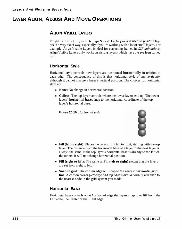
L a ye r s A n d F l o a t i n g S e l e c t i o n s
or
ntal
er
r ist of
LAYER ALIGN, ADJUST AND MOVE OPERATIONS
ALIGN VISIBLE LAYERS
Right-click|Layers| Align Visible Layers is used topositionlay-ers in a very exact way, especially if you’re working with a lot of small layers. Fexample, Align Visible Layers is ideal for correcting frames inGIF animations.Align Visible Layers only works onvisible layers (which have theeye iconturnedon).
Horizontal StyleHorizontal style controls how layers are positionedhorizontally in relation toeach other. The consequence of this is that horizontal stylealigns vertically,although it cannot change a layer’s vertical position. The choices for horizostyle are:
• None:No change in horizontal position.
• Collect: The top layer controls where the lower layers end up. The lowlayers’horizontal bases snap to the horizontal coordinate of the toplayer’s horizontal base.
• Fill (left to right): Places the layers from left to right, starting with the toplayer. The distance from the horizontal base of a layer to the next layealways the same. If the top layer’s horizontal base is already to the lefthe others, it will not change horizontal position.
• Fill (right to left): The same asFill (left to right) except that the layersare set from right to left.
• Snap to grid: The chosen edge will snap to the nearesthorizontal gridline. A chosen corner(left edge and top edge makes a corner)will snap tothe nearestnode in the grid system you made.
Horizontal BaseHorizontal base controls whathorizontaledge the layers snap to or fill from: theLeft edge, the Center or the Right edge.
Figure 20.10 Horizontal style
3 2 6 T h e G i m p U s e r ’ s M a n u a l

C h a p t e r 2 0
me.
rs
sther,
Vertical StyleVertical style controls how layers are positionedvertically in relation to eachother, so that theyalign horizontally.
• None: No change in vertical position.
• Collect: All of the lower layers snap theirvertical base to the verticalcoordinate of the top layer’s vertical base.
• Fill (top to bottom): Places the layers fromtop to bottom, so thedistance from the vertical base of one layer to the next is always the saIf the top layer’s vertical base is over the top of the others, it will notchange vertical position.
• Fill (bottom to top): Works the same way asFill (top tobottom), except that it works from bottom to top.
• Snap to grid: Snaps the vertical base to the nearestvertical gridline. A chosen corner will snap to the nearest node.
Vertical BaseVertical base controls whatvertical edge the layers snap to or fill from: the Topedge, the Center or the Bottom edge.
CollectUse Collect tostack objects in horizontal or vertical rows. To place your layeexactly on top of each other, chooseCollect from the Horizontal style and Ver-tical style pull-down menus, selectCenter from both the Horizontal base andVertical base pull-down menus, and click on the OK button.
FillFill is useful for animations where you want to move an object in equal stepframe by frame. If the layers are placed on top of each other, or very close togeyou’ll need to move them apart before you use Fill.
Figure 20.11 Verticalstyle
Figure 20.12 Fill
T h e G i m p U s e r ’ s M a n u a l 3 2 7

L a ye r s A n d F l o a t i n g S e l e c t i o n s
eas-
lay-ationdis-loser
u
.
n-
ause. Theant
ing
ixed
ted
Moving small layers is very easy. If you click on a small layer with theMovetool, that layer automatically becomes active, so you can drag and drop layersily without having to choose them in theLayers & Channels dialog.
You can’t precisely control the distance between layers, but if you spread theers as far apart as possible before alignment, you’ll get the maximum separbetween them after the alignment. As you align using Fill several times, thetance between layers reduces. Each time you use Fill, the layers move ctogether until the layers’ chosen edges touch.
Tip: Link the layers (with the cross symbol in the layer bar) after using Fill. Yocan then move all of the layers as a group.
Snap To GridSnap to Grid is indispensable for planning ananimation, with one problem: Thegrid created withGrid size is invisible.
So first, you need to make the gridvisible. To do this, create a new full-sized layerCreate a grid withright-click|Filters|Render| Grid and set theXSizeand theY Size to the same sizes used as Grid size for the invisible aligment grid.
Remember that different layers may snap to different nodes in the grid, beceach layer will snap to the node/line that is nearest to its chosen edge/cornerbest way to work with Snap to Grid is to place the layers close to where you wthem, andthen align them perfectly with Snap to Grid.
If the grid doesn’t work for you, you can always correct positions afterwards usGuides; see “Guides” on page 151.
Other Align Visible Layers ParametersThe Ignore the bottom layer even if visible checkbox is checked bydefault. This is wise in most cases. When you have created layers with a fbackground, you normally don’t want the background to start moving.
The Use the (invisible) bottom layer as the basecheckbox is notchecked by default. If you check it, then the background or bottom layer is trea
Figure 20.13 Snap to Grid
3 2 8 T h e G i m p U s e r ’ s M a n u a l

C h a p t e r 2 0
n if
.
ela-
antnt toable
thehich
than
ande to
ll belute.
like any other layer and is aligned as you align the other layers. Use this optioyou want to make a GIF animation with transparent background.
The Grid size slider and/or boxallow you to set the size of the invisible gridThe grid squares can measure up to 200 pixels.
ADJUST LAYERS
When you add a small layer to an image, you may want to adjust that layer in rtion to another layer or the image border.Adjust layers will help you do this inseveral ways. You must first choose the layer(s) or image border to which you wthe adjustment to be relative. Then, you need to specify the layers you waadjust. The adjustments are controlled by four checkboxes. As you see in T20.1, there are sixteen different combinations of the four checkboxes.
You can also select a layer in the pull-down menu. You should keep theLayers& Channels dialog up, so you can set the layers that should belinked, visibleor active. All these functions make it easy to adjust several layers againstimage border or another layer. You can, for example, use a combination in wyou adjustall linked layers againstall visible layers.
MOVE LAYER
Move Layer can be used to move one or several layers in a more precise waycan be done by hand with theMove tool.
Select a layer to move from the pull-down menu. The sliders set the distancedirection of the movement. If you want to move more than one layer you havcheck Affect visible layers, Affect linked layers or both. If you don’tcheck any of these buttons, only the layer selected in the pull-down menu wiaffected. You must also choose how to move the layers: Relative or Abso
Table 20.1 Adjust layers
Left Right Top Bottom Result
X Adjust to the left. No vertical change.X Adjust to the right. No vertical change.
X X Center layer horizontally. No vertical change.X Adjust to the top. No horizontal change.
X X Adjust to the top-left corner.X X Adjust to the top-right corner.
X X X Center layer horizontally and adjust to the top.X Adjust to bottom. No horizontal change.
X X Adjust to the bottom-left corner.X X Adjust to the bottom-right corner.
X X X Center layer horizontally and adjust to bottom.X X Center layer vertically. No horizontal change.
X X X Center layer vertically and adjust to the left.X X X Center layer vertically and adjust to the right.
X X X X Center layer in all directions.
T h e G i m p U s e r ’ s M a n u a l 3 2 9

L a ye r s A n d F l o a t i n g S e l e c t i o n s
yers
pearwant
en
at itanyoues.
thelue
inerec-oeslike a
erethea
fect
Relative will move the layers with the selected layer’scurrent positionas refer-ence.Absolute will move the layers with the imageborder as reference.
IMPORT LAYERS
Import Layers canimport one or more layers from another image. Thesourceimage can be bigger or smaller than thetarget image. There is a menu where youselect an image to import layers from, and several options for selecting what layou want to import. You can make importing easier by bringing up theLayers &Channels dialog.
As you can see in the interface, you can import the layers in the way they apin the source image, or in reverse order. You can also choose what layers youto import: linked (ones with the little cross),visible, selectedor all layers.To import a layer, press OK or Apply. Pressing Apply will keep the dialog opafter importing, so you can continue importing layers from other images.
TRANSFORMS
The Layers Transforms option is very similar to the graphic “drag and see whlooks like” Transforms tool, except that it doesn’t show you a preview. You cspecify each value in a coordinate system for very exact transforming, butmust know in advance what is going to happen when you specify those valu
PERSPECTIVE
The Perspective option allows you to change the position of each corner inoriginal layer by dragging the sliders or typing a coordinate value in the vafield. As is the case with theTransforms| Perspective command,skewwould perhaps be a more appropriate name thanperspective.Still, this tool is quiteuseful for making exact perspective or skew transformations.
ROTATE 3-D
Contrary to the Perspective commands, Rotate 3-D is atrue perspectivefilter.It is based on simple plane geometry, so it’s not difficult to understand. Imagyour image as a plane rotating on a ball joint, so that it can be turned in any dition. The x-parameter flips it around the horizontal axis and the y-parameter dthe same around the vertical axis. The z-parameter makes the image rotatewheel.
TheDepth option allows you to add more depth to the perspective, as if you wsmaller or the object was larger. An object that is enormous compared tobeholder (like a football field) will appear to vanish in the horizon, whereassmall piece of paper in the beholder’s hand will not show much perspective efat all, even though you see them from the same angle.
3 3 0 T h e G i m p U s e r ’ s M a n u a l

C h a p t e r 2 0
ualcre-sh
nc-
yer.the
our
-ontion
ROTATE ANY ANGLE
Rotate any angle is the perfect complement to theRotate tool in the toolbox. Thistool allows you to specify the exact rotation angle (instead of relying on manrotation or on 15 degrees of rotation at a time). Note, to make one degree inments, don’t drag at the slider; click on the left or right side of the slidebar pubutton.
SCALE
Scale makes your layer larger or smaller in both the X and Y directions. This fution alsomoves your layer as it scales it, so watch out for itsnew position!
SHEAR
Shear is a great complement to theShear tool, because it allows you to specifya precise shear angle, in the same way as theRotate any Anglecommand does.
FLOATING SELECTIONS
WHAT IS A FLOATING SELECTION?
When you first place a text string, move a selection or chooseright-click|Select| Float , your free, empty selection is transformed to afloatingselection with a pixel content.
This means that the selection contains information that isn’t attached to any laIt floatsindependently. Changes to a floating selection won’t affect the rest ofimage (note on theLayers tab on theLayers & Channels dialog how all ofthe layers are grayed out).
WHAT CAN YOU DO WITH A FLOATING SELECTION?
You are restricted by the “marching ants” selection border, but you can affect yfloat in the following ways:
You can change thecolor by using theright-click|Image options or byusing right-click|Filters on your selection. You can use theErasertool to reduce the selection, you canedit it with cut/copy/paste and you canmove the selection.
You can’t use any of theSelectcommands on a floating selection. You can, however, make a selectioninsidethe floating selection, and use Select commandsthat selection. Read more about moving and selecting within a floating selecin “Selections Within Floating Selections” on page 113.
T h e G i m p U s e r ’ s M a n u a l 3 3 1

L a ye r s A n d F l o a t i n g S e l e c t i o n s
ere
r
.
spacellownd-tside
cter
ec-
ed to
theade
, usee
he
yer,
spe-ber
Anchoring A Floating SelectionIn the Layers & Channels dialog, you can chooseAnchor layer (the buttonor from the right-click pull-down menu) and the float willmergewith the layerthat was active before you placed the float.
The simplest way to anchor a floating selection is to click your mouse anywhin the image (outside the floating selection if theMove tool is active).
You can save a float as anew layerby right-clicking on the Floating Selection bain the Layers & Channels dialog and clicking onNew Layer, or simply by click-ing the New Layer button. The new layer’s size will be the same as the float
In Photoshop, all layers are the same size as the image, but Gimp saves diskby adapting the layer size to the size of the floating selection. The dotted yelayer border, which you’ll see around your floated layer, constitutes the bouaries of the drawable surface in a layer. You can’t paint or make a selection ouof this border in that layer, and if you use theMove tool on that layer, you’ll movethe entire layer around.
Moving Objects In A Floating Selection LayerTo move an image object in a layer made from a floating selection (like a charain a text string), you must first select it (theLassoor theWand tools are goodchoices). When you try to move the selection, it will turn into a new floating seltion.
When you have moved the selection and released the mouse button, you neimmediately activate theMove tool, or you’ll just get irritating subselections (asdiscussed in “Moving Selections” on page 112). To avoid this, don’t moveselection with the first automatic move cursor that appears as soon as you’ve ma selection and you move your mouse cursor over the selection. Insteadright-click|Select| Float to select the float, then activate the Movtool and move your float.
When you’re happy with the position of the float, anchor it to the layer with tAnchor button or withright-click|Layers| Anchor Layer . Remem-ber that the text layer will be very small and snug unless you specified aBorderin the Text tool dialog. In order to anchor single text characters to the text layou may have to increase the layer size with theResize Layercommand (fromthe popup menu that appears when you right-click on a layer in theLayers &Channels dialog).
WORKING WITH FLOATING SELECTIONS
If you want to apply any of the selection options in the Select menu to createcial effects to a floating selection; a text string, for example, you should rememthe following guidelines.
3 3 2 T h e G i m p U s e r ’ s M a n u a l

C h a p t e r 2 0
nd
els
thisthingthat
ans.
ct
egeson
ngeand
yer,
Put The Float In A Layer Of Its OwnThere are two ways of doing this. Click on theNew Layer icon in the bottom ofthe Layers & Channels dialog or select New Layer from the right-click menu ayou’ll place the floating selection in a new transparent layer calledFloatedLayer. If you double-click on the Floating Selection bar in the Layers & Channdialog, you’ll place the floating selection in a new transparent layer calledFloat-ing Selection or Text layer if you’re placing a text string. As in any otherlayer, you can’t use Select menu options until you select something.
Select Menu Options In A Floated LayerTo apply effects likeright-click|Select| Border or right-click|Select| Feather , you must firstselectthe image object (e.g., text) inside thetransparent layer with theright-click|Layers| Alpha to Selec-tion command. This results in an ordinary non-floating selection, becausecommand selects everything with an alpha value greater than zero (everyopaque or semi-transparent in the layer). If a pixel’s alpha value equals zero,pixel is transparent.
If you have used Select menu options that will create alarger selection size thanthe original object selection, you’ll have touncheckthe Keep Trans. button inorder to apply paint to all parts of the new selection. This is because Keep Trpreserves all transparent pixels.
The Keep Trans. option allows you to paint an image objectwithout selectingit.If you use theBucket fill tool instead of a brush, you should remember to SeleAll to paint all letters at the same time.
The Size Of Floating Selection LayersSince theFloating Selection layer is reduced in size, filter effects and largselections may be cut off by the layer border. Also, if you make too many chanin the original layer, the pure form of the shape (especially for letters) will sodisappear.
This is why it’s usually a good idea to use a different layer for each effect. Chato alower layer to create special effects (the selection goes through all layers,you can choose any layer you want to work in). In a full-sized transparent layou need not worry about such restrictions.
T h e G i m p U s e r ’ s M a n u a l 3 3 3


C H A P T E R
21 ModesModes are powerful instruments for applying layersand paint. Gimp provides many different ways ofcombining layers and they’re all very useful. If youlearn how to use modes, you have learned a lotabout computer graphics.

M o d e s
rthey
the
the
ight
WHAT ARE MODES?Blending Modesor Transfer Modescontrol how the pixels in a foreground layeblend into the background layer(s). Modes are mainly used with layers, butcan also be used more directly as Paint Modes with theBucket tool, theBlendtool or any tool that usesBrush Selection. Gimp provides 15 different modes:
• Normal
• Dissolve
• Multiply
• Screen
• Overlay
• Difference
• Addition
• Subtract
• Darken Only
• Lighten Only
• Hue
• Saturation
• Color
• Value
• Behind(not available for layers)
The modes that are available for any of the painting tools are available fromMode pull-down menu on theBrush Selection dialog right-click|Dialogs| Brushes or File|Dialogs| Brushes .
The modes used for layers are available from the Mode pull-down menu onLayers & Channels dialog (right-click|Layers| Layers & Channels ).
NORMAL
Normal Mode is the default mode, and doesn’t do anything special, as you mexpect. A Normal Mode layer covers all other layers, unless there aretranspar-ent or semi-transparentareas in it.
Figure 21.1 Normal Mode
3 3 6 T h e G i m p U s e r ’ s M a n u a l

C h a p t e r 2 1
elythis
s-inyro-
els.olve
rentlid
olly
rent,ers offor
ther.
DISSOLVE
Dissolve Mode is very similar to Normal Mode, but this mode is used forsemi-transparency. It displays pixels as either completely transparent or completsolid, according to the level of opacity you set. In order to see the effect ofmode, you must first make the layer or paint transparent with theOpacity slider.
If you’re painting in Normal Mode at 50% opacity, you’ll get a smooth semi-tranparent surface. Dissolve Mode will instead produce noise effects similar to grafilm or granite rock. Instead of using semi-transparent pixels, Dissolve Mode pduces either entirelyopaqueor entirelytransparentpixels, 50% of each (if 50% istheOpacity value).
As you probably know, GIFs only include transparent or non-transparent pixIf you want a transparent GIF to look semi-transparent, you can use DissMode (or Holes in the right-click|Image|Alpha menu to achieve theeffect. This is good for rough, grainy effects, but a soft or smooth semi-transpasurface (glowing text for example) will probably look much better with a sobackground that is indexed to match the background on your page.
This mode is used with semi-transparency, where it displays pixels as whtransparent or fully solid, according to the level of transparency.
MULTIPLY
Multiply amplifies shadowsor dark areas of the image. You can compare it toputting two slides on top of each other on a light table. White areas are transpadark areas on top of dark areas become darker. Colors act as if they were laycolored glass on top of each other, or as color works in the CMYK color model (example, yellow + magenta = red).
This mode works with shadow, much like putting two slides on top of each o
Figure 21.2 DissolveMode
Figure 21.3 Multiply Mode
T h e G i m p U s e r ’ s M a n u a l 3 3 7

M o d e s
e
ite
t there
teren,
een.
; the
ing-ck,mtes)
ay
on a
SCREEN
Screen is the mode you should use to createhighlights in an image, and is inmany ways the opposite ofMultiply . You can compare it to projecting twoslides onto a film screen.
This mode depends onlight, so black is transparent (just like a black spot on onslide will allow the image on the other slide to show) andthe result is alwayslighter. Accordingly, the darker a layer is, the less it will affect the composimage, and vice versa.
In Screen Mode, white covers everything, gray shades get more transparendarker they get, and color is only visible if the other layer’s color permits it (we atalking about RGB color, so yellow + magenta = white, just like on your compumonitor or television set). Read more in “What Is The Difference Between ScreAddition And Lighten Only?” on page 346.
This mode works with light, much like projecting two slides onto the same scr
OVERLAY
Overlay Mode is something of a combination ofScreenandMultiply . Mediumgray is transparent in this mode. The background is the most important layeroverlay layer is only used for modifying the background.
Light and dark areas in the foreground affect the background by intensifyhighlights, color or shadows, so white, black or RGB|CMY parts of the background are not affected. In other words, you can’t intensify the shadow of blayou can’t highlight white areas and you can’t intensify a color with maximucolor value. Basically, the foreground affects the background (which dominaby intensifying color, highlights or shadows.
In this mode, allforeground colors appear paler and more washed out. Overlcolor and saturation depend mostly on thebackground. You can say that theforeground intensifies or modifies the background color; a green foreground
Figure 21.4 Screen Mode
Figure 21.5 Overlay Mode
3 3 8 T h e G i m p U s e r ’ s M a n u a l

C h a p t e r 2 1
ound
foresslsould.
gh-
lay-ther.re-
theunditsscale
dict,
fore-thect (a
but
n of
.
green background makes the image a little bit greener, whereas a red foregrwould make the green color slightly less green (but green nevertheless).
Overlay Mode is good for adding shadows and highlights to an image, orchanging the color temperature. It adds information to the existing brightnValue in your image, so you can “paint with light.” Hue and Saturation are achanged, but add no more effect than a cold shadow or reddish sunlight wo
The foreground affects the dominating background by intensifying color, hilights or shadows.
DIFFERENCE
The Difference Mode displays the difference between the RGB values in twoers. Foreground and background pixels have a dramatic effect on each oWhen you paint in Difference Mode, the corresponding pixels in both the foground and the background are evaluated and thedifferencebetween them is cal-culated.
If grayscale pixels are in one of the layers, the outcome is easy to predict. Ifforeground pixel is brighter than the one in the background layer, the backgropixel is inverted. If the foreground pixel is darker, the background pixel keepscolor. However, a grayish cast is added to the image, and the further the graypixel is towards white or black, the weaker this shade of gray gets.
If the pixels are colored or grayscale in both layers, the result is harder to prebut it works the same way:
| FG - BG| = outcome
In other words, the result is the absolute value of the difference between theground pixel and the background pixel. Black pixels in either the foreground orbackground are transparent (have no effect). White pixels have the most effewhite pixel alwaysinverts the correspondent pixel).
Difference Mode is usually very colorful, and can produce psychedelic results,it is also a powerful tool for displaying thedifferences between two layers.
For example, if you wanted to compare the size, shape and relative positiograyscale masks in different layers, you could useDifference Mode. Where theresults are black, the layers areidentical. Any small difference will appear veryclearly in this mode.
This mode displays the difference between the RGB values in the two layers
Figure 21.6 Difference Mode
T h e G i m p U s e r ’ s M a n u a l 3 3 9

M o d e s
of
tsGBite).
willon as
n be
alue.
lays-ter
ur-n. Ife-
ADDITION
Addition Mode is similar to Screen Mode. Addition Mode adds the RGB valuesforeground and background pixels. The result isalways lighterand often haswhite areas and unsharp edges.
This mode adds the foreground RGB value to the background RGB value.
SUBTRACT
Subtract Mode is theoppositeof Addition Mode and sometimes produces resulsimilar to Difference Mode. Subtract Mode subtracts the foreground color (Rvalue) from the background color (RGB value). If your background is wh(255,255,255), and you subtract red (255,0,0), the result is cyan (0,255,255
In Subtract Mode, a white shape in the upper layer against a white backgroundproduce a black shape. So far, the result is the same as for Difference. As soa foreground value exceeds the background value, however,Difference andSubtract produce different results, because a zero value in Subtract Mode caanegative value in Difference Mode.
This mode subtracts the foreground RGB value from the background RGB v
DARKEN ONLY
Darken Only Mode compares the foreground and background pixels and dispthe one with thelowestRGB value. Darken Only is somewhat similar to Multiply Mode. Color can only get darker, but Darken Only will usually produce lighcolors than Multiply.
If Darken Only worked on two pixels — one bright red (243,83,47) and one tquoise blue (47,239,201) — the result would be (47,83,47), a dark moss greeyou had usedMultiply Mode, the result would have been a similar, but somwhat darker green (44,77,37).
Figure 21.7 Addition Mode
Figure 21.8 Subtract Mode
3 4 0 T h e G i m p U s e r ’ s M a n u a l

C h a p t e r 2 1
owest
tur-lt of
at
ighest
s forfor
ght-
one,be
This mode compares the foreground and background pixels and chooses the lRGB value.
LIGHTEN ONLY
Lighten Only compares foreground and background pixels and displays thehigh-est RGB values. It is theopposite of Darken Only.
Using the same example, the result of Lighten Only used on the bright red andquoise pixels, would be (243,239,201), an eggshell bright beige. The resuLighten Only is similar to Screen Mode but is always lighter.
If you had usedScreenMode instead, you would get a similar, but somewhbrighter color (246,245,211). If you’d usedAddition Mode, you’d get a similarbutmuch brighter color (255,255,248) as a result.
This mode compares the foreground and background pixels and chooses the hRGB value.
HUE
Hue Mode results in a composite image that uses the background pixels’ valueValue and Saturation information, while using the foreground pixels’ valuesdetermining Hue information.
Hue Mode allows you to change the shade of an object without changing briness or saturation; it only affectscolor. The foreground color is the color you’llget, but you’ll keep the general feeling in the image; for example, a loud greensoft dark blue will be translated into a loud yellow on soft dark yellow. Whitblack or grayscale information in the background is not affected and can’t
Figure 21.9 Darken Only Mode
Figure 21.10 Lighten Only Mode
T h e G i m p U s e r ’ s M a n u a l 3 4 1

M o d e s
cale
ck-r
lorsgray,urs
tion,
e andou
t the
hichcanause
hile
tinted. Note that you cannot shift a color to grayscale in this mode. Graysinformation in the foreground comes out as a scratchy red.
A word of warning, or perhaps a tip, if you want to use this mode to tint a baground withcomplementarycolors next to each other (see “Complementary OInverted Colors” on page 194). Around the edges where complimentary comeet and blend, there will always be shades of gray. Because Hue cannot tintusing Hue Mode on top of such a background will produce thin, gray contoaround the objects (like a microscope would).
The composite image uses the background for Value and Saturation informawhile the foreground is only used for determining Hue.
SATURATION
In Saturation Mode, the composite image uses the background values for HuValue information and the foreground values for determining Saturation. Ymay use any color in the foreground. The background color won’t change, bubackground Saturation will, because it assumes the same saturation as thefore-ground color.
The Hue can’t be changed, unless you have a pure grayscale background, wwill become shades of red if the foreground contains color. Because youchange Saturation, this mode is often used with gray, white or black paint becthis desaturates the background.
The composite image uses the background for Hue and Value information, wthe foreground is only used for determining Saturation.
Figure 21.11 Hue Mode
Figure 21.12 Saturation Mode
3 4 2 T h e G i m p U s e r ’ s M a n u a l

C h a p t e r 2 1
andack-thealue
rs.de
hile
Sat-ue.e
d.de
ue is
beor of
hile
COLOR
Color Mode uses the foreground values for hue and saturation informationuses the background values to determine value information. Black or white bground pixels are not affected, but all other colors (grayscale or not) will gethue and saturation of the foreground color. Color Mode does not affect the V(brightness) of the background; dark and light information are left intact.
Color Mode is useful for tinting grayscale photos if you want strong, clear coloFor a softer tinting, or the look of an old photo, consider using Overlay Moinstead.
The composite image uses the foreground for Hue/Saturation information, wthe background is only used for determining Value.
VALUE
In Value Mode, the composite image uses the background values for Hue anduration information and uses the foreground information for determining ValValue is the same asLuminosityin Adobe Photoshop. Value Mode won’t changthe Hue or Saturation of the image, but will affectbrightness and shadows;i.e., the structure or 3-D-quality of the image.
Unlike Overlay Mode, Value Mode can’t distinguish a dark red from a bright reAll shadows or highlights disappear from the background and Value Modoesn’t deal with a grayscale background at all (because background valignored).
Value Mode is useful for correcting overbright or overdark colors, or it canused to transfer patterns or structures into an image, without changing the colthe image.
The composite image uses the background for Hue/Saturation information, wthe foreground is only used for determining Value.
Figure 21.13 Color Mode
Figure 21.14 Value Mode
T h e G i m p U s e r ’ s M a n u a l 3 4 3

M o d e s
dws.the
. (It
des.sityhich
col-
but
ible.irely
r
is-ence
esesee,
boththe
nd,
BEHIND
Behind Mode is only used forpainting (and not for layers). Don’t try to use thismode on anything solid, because it only affectstransparent or semi-transparent areas. When you paint in Behind Mode, it’s like painting on theothersideof the layer. If you pretend the layer is a wall with windows in it, the Behinpaint is applied to the outside of the house and is only visible through the windoIf the windows are dirty (i.e., are semi-transparent), the dirt will show againstBehind color.
This is a Paint Mode where only transparent areas are affected by the paintdoes the opposite of Keep transparent in the Layers dialog.)
COMPARING DIFFERENT MODES
The test squares shown in Figure 21.15 demonstrate the effect of different moThe black-and-white test squares range from black (intensity 0) to white (inten255) and are placed on top of a medium gray background (intensity 127), wexplains why the sixth square (also intensity 127) is invisible inNormal Mode.The colored test squares range from black through dark red to bright red. Theored background is a soft green.
As you can see,Screenmaintains the value variation of the grayscale squares,all shades are brighter than in the original.Lighten Only hasn’t changed thebrightness of the visible squares, but all dark squares have become invisAddition brightens up so much that most of the squares have turned entwhite, and black is invisible for all three modes.
Multiply , Darken Only and Subtract (grayscale) are the dark equivalents oopposites ofScreen, Lighten Only andAddition .
Overlay is only subtly different from the original. Note that medium grayinvisible in Overlay Mode. Difference shows the difference between foreground and background values. The dark colors represent a small differbetween foreground and background.
The Color and Hue test squares have assumed a uniform red color, so thmodes obviously use the Hue of the foreground, but not the Value. As youColor uses the Saturation of the foreground andHue uses the Saturation of thebackground.
TheSaturation test squares have turned uniformly green, so this mode usesthe hue and value of the background. Only the saturation is controlled to beforeground. TheValue test squares have turned softly green like the backgroubut the values come from the foreground
3 4 4 T h e G i m p U s e r ’ s M a n u a l

C h a p t e r 2 1
Screen Lighten Only Addition Overlay
Multiply Darken Only Subtract Difference
Color Hue Saturation Value
Normal (color) Normal (b/w) Dissolve (color)
Figure 21.15 Comparing modes
T h e G i m p U s e r ’ s M a n u a l 3 4 5

M o d e s
es,iffer-
nd
an-
oundundnd ish an
(a
77.
ted
lor is
cursthe
is
WHAT IS THE DIFFERENCE BETWEEN SCREEN, ADDITION
AND LIGHTEN ONLY?
Screen, Addition and Lighten Only Modes may appear very similar. Sometimtheir effects are almost as if they are the same mode, but certain important dences exist between them.
Lighten Only compares the foreground and background RGB values, achooses thehigher valuein each channel.
Addition adds up all values, so it ends up with a brighter image.
Screenmapsthe foreground against a background scale from 0-255 in each chnel, with the foreground pixel mapping its value to 0 (black) on the scale.
Imagine that two scales of equal length are on top of each other. The backgrscale goes from 0 to 255, while the foreground scale goes from x (the foregrovalue) to 255. The composite value is somewhere on the foreground scale, adetermined by the background scale. If the background is a grayscale witintensity of 100 (a medium dark gray), and the foreground’s intensity is 178medium light gray), the composite value can be calculated as follows:
The formula for Screen: composite value = FG + ((255 - FG) x BG)/ 255.
An example:
• The background scale consists of 255 equal parts.
• The foreground scale consists of 77 equal parts, because 255 - 178 =
• For 100 on the background scale, the foreground scale can be calculaas: 100/255 = FG scale/77.
• FG scale = (77 x 100)/255, so in this case the FG scale = 30.
• The composite value = 178 + the FG scale value, so 178 + 30 = 208.
The most obvious difference between the three modes is that Screen codarker than Addition color, butlighter than Lighten Only.
The main practical difference betweenLighten OnlyandScreenis that Screen isbrighter, and it allows more shades than Lighten Only does. This effect ocbecause Lighten Only is seldom affected by dark colors. It will just chooselighter color in all RGB values, if there is one.
The advantage ofScreenMode overAddition Mode is that Screen colors don’t“white out” as often as Addition colors (Addition colors white out because 255often the result from adding the values).
3 4 6 T h e G i m p U s e r ’ s M a n u a l

C h a p t e r 2 1
h
ening
wn.ss is
k atmi-e isore
WHAT IS THE DIFFERENCE BETWEEN MULTIPLY AND
DARKEN ONLY?
These two modes often result in similar outcomes, butMultiply is always a littledarker. As you know,Darken Only chooses the darkest RGB values in eacchannel to produce its result. The differences and similarities betweenMultiplyandDarken Onlycan be compared with the differences and similarities betweScreenandLighten Only(note that Subtraction can be thought of as correspondto Addition, if you inverted the top layer).
Multiply is mathematically the opposite ofScreen. In Screen, the foregroundvalue is mapped to zero and up, but in Multiply it is mapped to 255 and doTherefore, the foreground value is the lightest possible value and its darknedetermined by the background value.The algorithm is simple: the com-posite value = FG x (BG/255).
For grayscale images, the difference is much more evident. If you take a loothe pictures portraying these modes, you’ll find that Darken Only looks setransparent, whereas Multiply looks as transparent as a slide. Multiply Moddarker and shows a lot more of the background. In color images, you’ll get mcolor variation (for lighter colors) withMultiply than you would withDarkenOnly.
Figure 21.16 What’s the difference between Addition, Screen and Lighten Only?
Addition Lighten Only Screen
T h e G i m p U s e r ’ s M a n u a l 3 4 7

M o d e s
the
Sat-ce
re
rues
WHAT IS THE DIFFERENCE BETWEEN COLOR AND HUE?
Hue and Color sometimes produce similar results, because in both casesforeground controls the compositeHue, and thebackground determines theValue. The difference is based on which layer controlsSaturation. In Hue Mode,the background controls the saturation and inColor Mode, the foreground con-trols the saturation.
Generally, Hue and Value are the most important parameters in an image. Ifuration is roughly the same in both layers, it will be hard to tell the differenbetweenHue andColor Modes.
You will be able to tell the difference if one of the layers is grayscale, or if theis a lot of variation in the Saturation of a layer. Another way to think of it:ColorMode is often used toadd color to a grayscale, so it’s important that the top layecontrols Hue and Saturation, but it must not interfere with the dark or bright valof the background.
Hue Mode, on the other hand, is often used forchangingthe existing color ofa certain object. In that case, you don’t want to change theSaturationin the back-ground, because then the object would look very unnatural.
Figure 21.17 What’s the difference between Darken Only and Multiply?
Darken Only Multiply
3 4 8 T h e G i m p U s e r ’ s M a n u a l

C h a p t e r 2 1
Color
Hue
Figure 21.18 In Color Mode, you can seethe leaf pattern of the foreground clearly,although no brightness value from the FGhas been used in the composite image
Figure 21.19 In Hue Mode, the onlyvisible effect of the foreground is the greencolor of the leaves (see the color section);because saturation is taken from thebackground, the only part of the image thatis really green is the face (which had thehighest saturation)
T h e G i m p U s e r ’ s M
a n u a l 3 4 9

C H A P T E R
22 Channels And DuotonesChannels are a resource that beginners often leaveunused in programs with channel capability. Learnhow to use them, and you won’t be able to livewithout them!

C h a n n e l s A n d D u o t o n e s
ed,
-atof
it at
y the
ne orthe
reheyel, ors all
ste)ov-gs,
RGB CHANNELS
COLOR CHANNELS
The Channels tab displays the three RGB channels, showing the current rgreen or blue color values of each pixel in your image. The RGB channelthumb-nails are grayscale representations of each color channel, wherewhiterepresents100% color, andblack represents no color.
The RGB channels each have aneye icon, so you can look at your image in a single color channel. Clickoff the eye icon in the Blue and Green channels, so thonly theRedchannel is visible. Bright red in the red channel is the equivalenta maximum red value for that pixel; black means that the pixel has no red inall. If all three channels have maximum values for an area, that area iswhite.
The RGB channels are always active when a layer is active, and they displacolor values ofall visible layers, not just the active one. Unlikelayers, the RGBchannels can all be active at the same time. You can also choose to work in otwo specific color channels, by clicking on the appropriate channels to activateones you want and deactivate the ones you don’t want.
Normally, working directly in RGB channels isn’t that useful. However, if you avery skilled and you like to experiment with patterns and advanced coloring, tcan be of interest. For example, you can erase or add things to the red channtry a filter on the blue channel, etc. Remember that although the channel showvisible layers, the operation only affects theactive layer.
Also note that you can’t use the standard edit functions (like Cut, Copy and Pain a single RGB channel. You can move selections in a color channel without ming the content of all three RGB channels. If you want to do either of these thinuse right-click|Image|Channel Ops| Decompose and right-click|Image|ChannelOps| Compose.
Figure 22.1 On the Layers &Channels dialog (right-click|Layers|Layers & Channels),click on the Channels tab.
3 5 2 T h e G i m p U s e r ’ s M a n u a l

C h a p t e r 2 2
re is
caletheels.
val-
.
alue
logdia-foreot be
eddd
youthe
use.
than
ALPHA CHANNELS
ALPHA VALUES AND TRANSPARENCY
An alpha value describes the amount oftransparencyin a pixel. Every pixel hasa value for the Red, Green and Blue channels in the RGB system, and if theanAlpha channel (RGBA) every pixel also has analpha value.
Note: Unlike the RGB channels, you can’t see the true alpha channel or graysrepresentation of your image’s current alpha values. It is not displayed inChannels tab, and should not be confused with the static alpha mask chann
If you’d like to see a grayscale representation of your image’s current alphaues, you can do so bydecomposingyour image with theright-click|Image|Channel Ops| Decompose command and decompose to RGBAYou can also use theright-click|Layers| Alpha To Selectioncommand followed by theright-click|Select| Save To Channelcommand to save the current alpha values in a new channel.
Just like the RGB values, alpha values range from 0 to 255. The maximum v(255) represents 100%opacityin that pixel, and 0 represents totaltransparency.You can check this out with theColor Picker (eyedropper tool) in the toolbox.The transparency or alpha values will be displayed in the little Color Picker diabox that appears when you click on different parts of the image. If the Pickerlog showsN/A, it’s because your image contains no alpha channel and therecannot display transparency, just as an image without a red channel would nable to display red color.
ENABLING TRANSPARENCY
When youeraseor cutsuch an image, the “holes” you make will only display thbackground color (the background color swatch in the toolbox). Now, if you aa new layer to this image, you will find that it is different from the backgrounlayer. All layers that you add to an image contain alpha information, so whenuse the eraser on the new layer, you will see the underlying layers throughtransparent hole you just made.
To enable transparency in the background layer, you must first select theAddAlpha Channel option in theLayers menu. If you chooseTransparent asFill Type when you create a new image, none of this will be necessary becathis command will produce anRGB-alpha image with a transparent background
ALPHA MASK CHANNELS
The real reason to use the channels is the ability tostoreandedit selections inalpha mask channels. Whenever you make a selection that is more complexa square, you should save it in a new channel so that you can use it later.
T h e G i m p U s e r ’ s M a n u a l 3 5 3

C h a n n e l s A n d D u o t o n e s
nels,l
nse-ls are
ro, orhich
hat’smaskk in
u’llnse tottingans-as the
ion onofcolor,
A
youeasferent
ight.
on’tard to
ur
When you open theChannelsdialog and create aNew Channel, you create amask,which can be translated to a selection and applied to a layer. These chanwhich we can refer to asalpha mask channels, have nothing to do with the actuaalpha values present in your image.
RGB channels display the color values in each pixel in the image, and coquently change automatically when the image is altered. Alpha mask channenothing like that. They are staticstorage channelsthat won’t change with yourimage. Just like in the RGB channels, black represents an alpha value of zefull transparency, and white represents areas where the alpha value is 255, wis the same as full opacity.
Note: A layer and an alpha mask channel can’t be active at the same time. Twhy the three RGB channels are grayed out as soon as you click in an alphachannel. To return to your image, you must switch to the Layers tab and clicone of the layers.
If you turn off all layers (and other channels) and only look at one channel, yosee it the way it looks in the thumbnail — a clean black-and-white representatioof the Alpha channel. The way channels appear on screen, should you choodisplay them together with other channels or layers, can be compared to puslides on top of each other. White mask areas (which represent opacity) look trparent, and black areas (which represent transparency) appear as opaqueFill Opacity value that you have specified.
Note that the way the channel values appear on screen is quite theoppositeof thealpha values they represent. This means that loading an alpha channel selecta white layer and filling it with black will result in an image that is a negativethe channel image. You can also choose another color than black as maskin which case this color will appear on screen instead; see “Adding Color ToChannel” on page 355.
When you activate an alpha mask channel with theChannel To Selectioncommand (right-click in the Channels dialog to access the Channels menu),have created aselectionwhere black mask areas remain unselected, white arrepresent fully selected parts and the shades of gray in between represent diflevels of “selection.” When you apply thisselection maskto a layer, the oper-ations performed will only affect the areas where the channel image was brThe dark areas of the mask will protect the original image.
STORING SELECTIONS AS CHANNELS
Theright-click|Select| Save To Channel option allows you to save aselection as a channel. Create a selection, click onright-click|Select|Save To Channel , and open the Layers & Channels dialog (right-click|Layers| Layers & Channels ). A new channel will now appear:SelectionMask copy.
Selection Mask copy is a grayscale version of the selection you just made. Dforget to rename the channel, because selections stored in channels may be hrecognize. To name the channel, double-click on its old name and theEditChannel Attributes dialog will appear. Name the new channel whatever yoselection represents (or will represent when you have edited it).
3 5 4 T h e G i m p U s e r ’ s M a n u a l

C h a p t e r 2 2
tcityagent, itwiths is
ttonn on
nake
therk
youcre-
te ornu).
ers.
nel
ordi-vicelpha
e for
gesr
atch
if
You can set aFill Opacity value in the Edit Channel Attributes dialog, but iwon’t affect the alpha values in your channel. The reason you set the fill opato a transparent value in this dialog is that this will enable you to see your imthrough the dark parts of the channel. If the mask wasn’t somewhat transparewould be impossible to edit the channel properly. The channels are displayeda 50 percent opacity when you make them visible (with the eye icon), but thijust a default value.
When you want to use the selection you just stored, click the right mouse buon the channel’s name, and a popup menu will appear. Choose the last optiothe list: Channel To Selection. Channel To Selection will create a selectiobased on your channel. Switch to the Layers tab, click on one of the layers to mit active, and your selection will be available for use. Remember to toggle offvisibility (eye icon) of the channel, so that it will not disturb you when you wowith the new selection.
EDITING ALPHA CHANNELS
The buttons in the bottom of the Channels dialog box, or in the popup menusee when you right-click on a channel, should be easy to understand. You canate a new channel, raise or lower a channel in the channel hierarchy, duplicadelete a channel and change channels into selections (only in the popup me
You can’tmergechannels, unless you first copy them and paste them into layMerge those layers with theright-click|Layers| Merge VisibleLayers command, then you copy or cut the layer and paste it into a chanagain.
As you see, the contents of alpha channels and layers can be edited just as innary images. You can paste an image or a layer into an alpha channel, andversa. You can paint, adjust image values, make selections or use filters on achannels. These capabilities make channels the most powerful tool availablcreating advanced selections.
Just remember that alpha channels belong to Gimp’s native file formatXCF. Aslong as your image contains alpha mask channels it is considered to beLayered.You can’t flatten an image with alpha channels, and because layered imacan’t be converted, you’ll have todeleteall alpha channels before converting youimage to a working file format like TIFF or GIF.
USING CHANNELS FOR SPOT COLOR SEPARATION
ADDING COLOR TO A CHANNEL
You can change the mask color of an alpha channel by clicking the color swin the New Channel Optionsdialog, if you create anewchannel, or theEditChannel Attributes dialog (accessed by double-clicking the Channel bar),you wish to edit anexisting channel.
T h e G i m p U s e r ’ s M a n u a l 3 5 5

C h a n n e l s A n d D u o t o n e s
or.olor
o the
d
ask—
n-e
Warning: This will only change how the channel is displayed on your monitYour alpha channel is still a grayscale representation of a selection, not a cchannel.
When you replace the blackmask colorwith another color, this color and brighter(but never darker) shades of it are now the only things the channel can add tmonitor display. This is similar to the way aprinting plate adds ink to a paper.If you toggle off the visibility for all layers, you’ll see what such a plate woullook like.
Take a look at Figures 22.2 and 22.3 to appreciate the difference between acol-ored layer and acolored channel. For example, a yellow channel and a yellowlayer look just about the same. However, if you were to copy the yellow mchannel and paste it into a grayscale image, it would look like Figure 22.3crisp, clear and entirelyblackin areas that were 100% yellow in the colored chanel. Figure 22.2 shows what the yellow layer would look like if you did the samthing. The yellow brightness values have been translated to light shades ofgraywithout contrast.
This means that you can usechannelsbut not layers as originals for makingprinting plates. Only channels will reproduce this image faithfully with thespecified yellow ink.
Figure 22.2 A yellow layercomes out as pale gray when it isconverted to grayscale. If thisimage file is used for making aprinting plate, the printed resultwill be much paler than theoriginal yellow layer.
Figure 22.3 This is thegrayscale representation of achannel with the same yellowcolor as in the layer. This imagewill produce a plate capable ofprinting the same shade ofyellow that was specified in thechannel.
3 5 6
T h e G i m p U s e r ’ s M a n u a l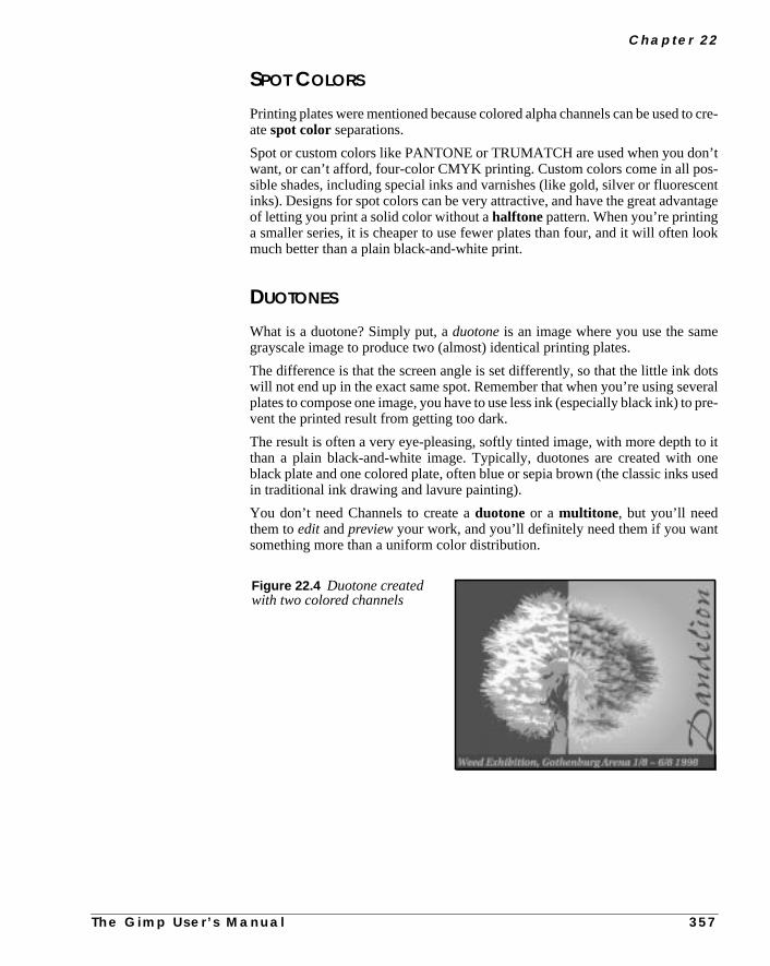
C h a p t e r 2 2
to cre-
n’ts-centntage
ook
e
otseralpre-
to itoneused
SPOT COLORS
Printing plates were mentioned because colored alpha channels can be usedatespot colorseparations.
Spot or custom colors like PANTONE or TRUMATCH are used when you dowant, or can’t afford, four-color CMYK printing. Custom colors come in all posible shades, including special inks and varnishes (like gold, silver or fluoresinks). Designs for spot colors can be very attractive, and have the great advaof letting you print a solid color without ahalftone pattern. When you’re printinga smaller series, it is cheaper to use fewer plates than four, and it will often lmuch better than a plain black-and-white print.
DUOTONES
What is a duotone? Simply put, aduotoneis an image where you use the samgrayscale image to produce two (almost) identical printing plates.
The difference is that the screen angle is set differently, so that the little ink dwill not end up in the exact same spot. Remember that when you’re using sevplates to compose one image, you have to use less ink (especially black ink) tovent the printed result from getting too dark.
The result is often a very eye-pleasing, softly tinted image, with more depththan a plain black-and-white image. Typically, duotones are created withblack plate and one colored plate, often blue or sepia brown (the classic inksin traditional ink drawing and lavure painting).
You don’t need Channels to create aduotone or a multitone, but you’ll needthem toedit andpreviewyour work, and you’ll definitely need them if you wantsomething more than a uniform color distribution.
Figure 22.4 Duotone createdwith two colored channels
T h e G i m p U s e r ’ s M a n u a l 3 5 7

C h a n n e l s A n d D u o t o n e s
beat
pec-ou
ave
he
And
for-
ChecklistBefore you create a spot color multitone, you should consider a few things:
What spot colors should be used?
You can choose from a great variety of custom colors, so this problem cansolved in two different ways. You can go to your local print shop, take a lookits color charts and ask it to make acolor calibrated proof of your chosencolors to take home, or you can buy an expensive PANTONE color chart and sify (to your printer) the custom colors that look most like the RGB colors ychose for your alpha channels.
Remember that the color in the alpha channels is for preview only — as we halready explained, all channels are really grayscale.
In what order should the plates be printed and the channels be placed?
Always ask your printer’s advice about this. Ask them in whatorder they preferto print the different inks, and the approximatedensityof the last ink to be applied.You should probably also discuss whatscreen angleanddot gainyour printerthinks would be appropriate for this print job and whether you should useAM orFM screening. As always, make a color proof that you’re satisfied with and tell tprinter to adjust the final settings to look like your proof.
For more information on printing procedures and pre-press, see “Pre-pressColor In Gimp” starting on page 197.
HOW TO CREATE A DUOTONE
Preparing Your ImageOpen the image you want to turn into a duotone. If the image contains color inmation, you should firstdesaturate it (right-click|Image|Colors|Desaturate ) andincrease thecontrast somewhat.
The image should be black where you want full ink coverage (right-click|Image|Colors| Brightness-Contrast ).
Figure 22.5 The originalimage
3 5 8 T h e G i m p U s e r ’ s M a n u a l

C h a p t e r 2 2
d, butnnel
the
l-
-plate
.g.,
show
Copy the image and thenClear it so that only awhite background remains(right-click|Edit| Copy and Edit| Clear ). This way you’ll knowthat the target image is exactly the same size as the image you have just copieyou can just as well create a new white image and paste your picture in a chathere.
Make sure that theeye iconis turned on in thewhite background layer on theLayers & Channels dialog (right-click|Layers| Layers & Chan-nels ). Thewhitelayer represents the paper color, and is necessary to displaycolors.
Creating A Colored ChannelOpen theChannels tab and create a new channel. In theNew ChannelOptions dialog, set this channel to 100%Fill Opacity . Click the black colorswatch to access theColor Selectiondialog, and choose a nice color (this wilbe the first plate to be printed).Namethe channel “navy blue” or the like, depending on what color you chose. Click on theOK button.
Paste(right-click|Edit| Paste ) the image into this channel. Then create anewchannel and repeat these steps for this channel (which is the secondto be printed), only this time set theFill Opacity to 85% (or to the value thatyour printer thinks is closest to the density of this ink). Name this channel, e“tawny yellow”.
Now you can manipulate the contents of the channels. Figures 22.6 and 22.7how we adjusted our channel images for a nice artistic output.
Figure 22.6 Screenshot ofthe blue spot color channel
Figure 22.7 Screenshot of theyellow spot color channel
T h e G i m p U s e r ’ s M
a n u a l 3 5 9
C h a n n e l s A n d D u o t o n e s
in
-
xtnel
e isnd
bothctlyhe
els
twolete
Adjusting Color With Mask ChannelsSometimes you only wantoneof the custom inks in a duotone to show in a certapart of the image.
In this case we want the textDandelionto be printed with a pure blue, that is, without a trace of the yellow ink. To achieve this, we wrote the wordDandelionin atransparent layer and selected this text string using theright-click|Lay-ers| Alpha To Selection command.
Then westoredthe text in a new channel withright-click|Select| SaveTo Channel . We named the new channel “Text Mask”, and loaded the teselection from the Text mask channel by right-clicking on the Text mask chanicon and selecting Channel To Selection.
Then, we clicked on the Blue channel icon and filled the selection withblackcolor (because black will display as 100% of the mask color, which in this casblue). Then, we turned to the Yellow channel with the selection still active, afilled it with white color (because white displays as transparent).
This way we made sure that the text was placed in the exact same position inchannels, and that the blue plate would print a full coverage of blue ink exawhere we wanted it, and that the yellow plate wouldn’t put any ink at all in tsame spot.
Converting Channels To Grayscale ImagesWhen you’re satisfied with the duotone image, it’s time to convert the channinto something that will be useful to your printer. They will need twograyscaleimages to print your duotone, one for each plate.
Duplicate the image file (Ctrl+D), then copy and paste the contents of thechannels to the white background layer of each file. When this is done, you deall other channels and layers and convert the images fromRGB to grayscale(right-click|Image| Grayscale ). Save grayscale number 1 asblue.tifand grayscale number 2 asyellow.tif.
Figure 22.8 The Text maskchannel
3 6 0 T h e G i m p U s e r ’ s M a n u a l

C h a p t e r 2 2
lors.r that
Instructions To The Service BureauGive the files and a proof of what the final print should look like (make ascreengrab of your image with theXtns| Screen Shot command and print it on anordinary inkjet printer) to your printer or service bureau, specify the custom cofor “blue” and “yellow” and tell them in whatorder the plates should be printedAsk your printer to set an appropriate screen angle and dot gain. Remembethey are the experts, so you are well advised to follow their instructions.
T h e G i m p U s e r ’ s M a n u a l 3 6 1
P A R T
VI Filters• ANIMATION
• ARTISTIC
• BLUR
• COLOR
• COMBINE
• CRYPTOGRAPHIC
• DISTORT
• EDGE-DETECT
• ENHANCE
• GENERIC
• GLASS EFFECTS
• LIGHT EFFECTS
• MAP
• MISCELLANEOUS
• NOISE
• RENDER


C H A P T E R
23 An Introduction To FiltersA short description of how filters generally workin Gimp.

A n I n t ro d u c t i o n To F i l t e r s
r to
vail-yourg-
orduskeor
ptermailthis
one
playse wehe fil-
by
o
lyice
ardithhe.
PLUG-INS
When a Photoshop user thinks ofplug-ins, things like Eye Candy and Kai’s PowerTools come to his or her mind. Gimp plug-ins are similar: They permit the useadd extra featuresto Gimp. By features, we meanfilters, printer drivers ,mail interfaces, save/write modules, etc. Gimp is very modular; nearlyevery function besides the basics is done by plug-ins.
Many Gimp users/developers have written Gimp plug-ins and made them aable to the Gimp community. We encourage you to do the same. If you createown plug-in, submit it to the Gimp community under the GPL license. Your pluin will make Gimp even better.
In these chapters, we will discuss theFilters menu. We are going to call these fil-tersplug-ins, because that’s what most people think of when they hear the w“plug-in”. The Script-Fu menu is similar to the Filters menu because Script-Fcan be applied as ordinary filters to your images. You’ll find that you can mayour own filters quite easily, without expert knowledge of C programmingGTK+ libraries.
Because plug-ins and scripts develop rapidly in the Gimp community, this chacan’t be as up-to-date as we would like. We encourage developers to send usabout their new or changed plug-in so that we’ll have an easier job updatingchapter. In “Compiling Plug-ins” starting on page 769, you’ll find some tipshow to compile plug-ins. You may also want to visit the filter developers’ hompages to get up-to-date information about the filter.
Please note that the screen shots of the plug-in dialogs won’t necessarily disthe same values that we used to generate the resulting image. This is becausometimes need to exaggerate a bit so that you can really see the effects of tter.
MAIN CATEGORIES
The Filters menu includes the following submenus, which group plug-insfunction:
• Animation: Includes an animation player that lets you play Gimpanimations and an animation filter that can optimize your animation, sthat it uses much less disk space.
• Artistic: Includes filters to create instant artistic effects. You can easilycreate cubist paintings, mosaic patterns, etc. This kind of filter is mainused for adding special effects to an image, but you can also create npatterns with it.
• Blur: Includes many different types of blur filters. Blurring is usefulwhen you want to soften part of a picture. Real shadows are seldom hand solid, so to create realistic shadows you’ll want to soften them up wan appropriate blur filter. A portrait may look too honest and show all timperfections and wrinkles of the model, so blurring the portrait will help
3 6 6 T h e G i m p U s e r ’ s M a n u a l
C h a p t e r 2 3
as
to
likel
ines
can
s,
r
e
nd
• Colors: Includes tools that can manipulate color and HSV values, justif you were standing in a darkroom.
• Combine: Provides many different ways of combining several images create a new image.
• Crypt: These filters allow you to sign, encrypt/decrypt your image orsend hidden files Notice that this item is not a part of the core Gimpdistribution.
• Distorts: Creates the kinds of effects you’d find in a hall of mirrors.Some of these filters are great for adding special effects to an image,making ripples in a water surface. If you want to create textures, you’lfind many useful filters here.
• Edge-detect: These filters help you find the edges or color boundariesan image, which can be quite useful when you work with layered imagand you want to strengthen or smooth the contours of an object. You also use edge-detect filters for making easy selections with the magicwand, or easy fills with the Bucket fill tool.
• Generic: Includes mathematical filters that use a matrix for imagemanipulation. You can perform all kinds of manipulation with these filterbut you may need some math up your sleeve.
• Glass Effects:Includes filters that create different kinds of lens orcurved mirror effects.
• Light Effects: These filters add a little glamour (extra shine, lustre,glitter or star reflections) to your designs.
• Map: Includes filters that allow you to bump map, displace or alter youimage in relation to an image map.
• Miscellaneous:Includes filters that don’t fit anywhere else. Currently,these include stereogram filters and video screen simulation.
• Noise: These filters will add noise effects to your image, like monitornoise, film graininess or just pointillistic artistry.
• Render: These filters will render all kinds of shapes or objects, and arextremely useful for creating textures or patterns.
Notice the handy shortcuts: Shift+Alt+f will bring up the last plug-in you used aAlt+f will apply the last filter again.
T h e G i m p U s e r ’ s M a n u a l 3 6 7


C H A P T E R
24 Animation FiltersDescriptions of the different animation filters andfunctions available as well as a description of GIFanimation.

A n i m a t i o n F i l t e r s
n,.
andon
er to
ata-
his
ANIMATION FILTERS IN THE FILTERS MENU
ANIMATION PLAYBACK
Animation Playback will display your layers or GIF animation as if itwere a piece of film. If the layers don’t contain specific animation informatioeach layer will be run inCombine mode. You can also step through each frame
This plug-in can also show you apreviewof what an image will look like in a webpage. You can grab the image in the playback frame, drag it out of the framedrop the image on another window (including a browser window). Just clickthe image and drag it to where you want it to go.
Note that the image doesn’t need to be layered (i.e., a playable image) in orduse this function. You can use it on any ordinary JPEG, GIF or TIFF image.
ANIMATION OPTIMIZE
A GIF animation is built of many layers. Some of the layers will probably repemuch of the information in the previous layer (the previous frame in your animtion). Wouldn’t it be great if you could skip all that unnecessary information? T
Figure 24.1 Animation Playback’s preview function; thisillustration shows an image being dragged into theStarOffice canvas
3 7 0 T h e G i m p U s e r ’ s M a n u a l

C h a p t e r 2 4
an
use
t isgly
ter
gethis
byg
ach
s ame.and
would be difficult and time-consuming to do by hand, but there is a filter that cdo it for you.
Open your animation file and applyright-click|Filters|Animation|Animation Optimize . Now look at your layers. The layers will be muchsmaller, because onlyadditionalor diverginginformation is displayed. This filterwill make GIF animations much smaller and faster to download. You can alsothis filter on large, multi-layered XCF files to reduce their size.
ANIMATION UNOPTIMIZE
After you have optimized an image (using Animation Optimize or by hand), iusually quite hard to scale and your manipulations will often produce an uresult. The Animation Unoptimize filter solves this problem, so use this filbefore you make any alterations to an optimized image.
FILTER ALL LAYERS
Filter All Layers is used to create animations with theGAP plug-in (see“Advanced Animation With Gimp Or How To Use AnimFrames” starting on pa639), but you can apply it to any kind of multi-layered image. When you selectfilter, a browser will appear. The browser is much like theDB Browser, exceptthat only plug-ins are listed.
Select the filter that you want to apply, and specify how you want to apply it,selectingconstantor variable. When you have made your choice, a filter dialowill pop up asking for values. If you choseconstant, the dialog will appear onlyonce, and the values you specify will apply to all layers. If you chosevariable,the dialog will appear for every layer so you can apply different values to elayer.
HOW TO CREATE A GIF ANIMATION
Gimp is a great tool for creating GIF animations. Gimp treats each layer aframe. The Background layer is Frame 1 and each new layer is a new fraWhen you add a new layer to the background layer, name it Frame 2, Frame 3so on.
SPECIFYING THE DELAY OF EACH FRAME
Edit the layer name by double-clicking on a layer in theLayers & Channelsdialog. Rename itFrame X (xxxxms), whereX is the frame number andxxxxis the delay in milliseconds. Naming a frameFrame 5 (100ms)will give thatframe a delay of 100 ms.
T h e G i m p U s e r ’ s M a n u a l 3 7 1

A n i m a t i o n F i l t e r s
e 2and
the)
out
as
COMBINING FRAMES
To make a layer combine with the previous layer (combine means that Framwill be added to Frame 1 (the background), Frame 3 will be added to Frame 2Frame 1, and so on), name the layerFrame X (xxxxms) (combine).
REPLACING FRAMES
To make the animation work like a real movie (i.e., each new frame replacesformer), add (replace) instead of (combine). You can (combine) and (replacein any order.
Note that when you save your GIF, you’ll see a dialog box that asks you abDefault disposal where unspecified. Don’t check Don’t care because thatwill make the layers combine without showing up in the Gimp layer dialog(combine). Just choosecombine, and the settings in the layer dialog will still bepreserved.
An example of five layers/frames:
• Background (100ms) (replace)
• Frame 2 (100ms) (combine)
• Frame 3 (100ms) (replace)
• Frame 4 (100ms) (combine)
• Frame 5 (100ms) (replace)
Figure 24.2 The Layer dialog,showing the frame(layer), name,time and how to combine it.
3 7 2 T h e G i m p U s e r ’ s M a n u a l

C h a p t e r 2 4
lay
etck-in.
The previous five frames will be played back in this order with a 100 ms debetween each frame:
• Background
• Frame 2 + Background
• Frame 3
• Frame 4 + Frame 3
• Frame 5
• Background
and so on until you stop it.
Note:Combine combines the frame with the previous frame, but if you have sthe background layer to combine, it will not combine with the top layer. The baground layer will always replace the top layer when the loop starts over aga
T h e G i m p U s e r ’ s M a n u a l 3 7 3

C H A P T E R
25 Artistic FiltersArtistic filters create instant artistic effects like oilpaintings or mosaic floors. In general, they areready-to-run filters that demand little input from theuser.
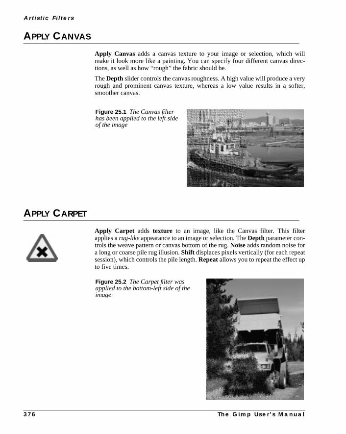
A r t i s t i c F i l t e r s
illc-
eryfter,
t
APPLY CANVAS
Apply Canvas adds a canvas texture to your image or selection, which wmake it look more like a painting. You can specify four different canvas diretions, as well as how “rough” the fabric should be.
TheDepth slider controls the canvas roughness. A high value will produce a vrough and prominent canvas texture, whereas a low value results in a sosmoother canvas.
APPLY CARPET
Apply Carpet adds texture to an image, like the Canvas filter. This filterapplies arug-likeappearance to an image or selection. TheDepth parameter con-trols the weave pattern or canvas bottom of the rug.Noiseadds random noise fora long or coarse pile rug illusion.Shift displaces pixels vertically (for each repeasession), which controls the pile length.Repeatallows you to repeat the effect upto five times.
Figure 25.1 The Canvas filterhas been applied to the left sideof the image
Figure 25.2 The Carpet filter wasapplied to the bottom-left side of theimage
3 7 6 T h e G i m p U s e r ’ s M a n u a l

C h a p t e r 2 5
rea;
dif-
e
the
ensee
ss the
CUBISM
Cubism transforms your image into cubist art. If you checkUse backgroundcolor, the background color will appear between your tiles; otherwise, this awill be black. Tile Size determines how “cubist” you want your image to behigher values result in a more abstract image. TheTile Saturation value spec-ifies howcolorful the image will be.
Tip: To achieve interesting effects, try applying Cubism to several layers withferent modes over the original image.
GAGGenetic Algorithms for Gimp, or GAG, is a pattern-generating Render filter likright-click|Filters|Render| Qbist .
When you open GAG, the display shows nine randomly chosen patterns fromGAG pattern library. Pressing theNew Generation button will generate newpatterns.
Each pattern swatch is equipped with a smallWeight Scale slider. This sliderdetermines theweightor influence of this pattern for the next generation, so whyou have found one or more patterns or themes that you like and would like tomore variations of, set the sliders in accordance to your preferences and preNew Generation button.
Figure 25.3 Cubist cat at thebottom-left side
T h e G i m p U s e r ’ s M a n u a l 3 7 7

A r t i s t i c F i l t e r s
n by
tion
THE GAG RIGHT MOUSE BUTTON MENU
To slightly mutate a single pattern, press theright mouse buttoninside the patternbox and selectMutate. The amount of mutation can be set in theOptions dialogin theMutation tab with theProbability of Mutation slider.
To get an entirely different pattern, right-click and selectRandom, and GAG willgenerate a new, randomly chosen pattern.
If you are an experienced Scheme programmer, you can try to modify a patterhand by selecting theEdit by hand option in the right-click menu. To get a bet-ter view of the pattern, select theMagnify option. This opens an X Window thatdisplays the pattern magnified by 2.5.
To render the pattern into an existing image, select theRender picture optionand choose an image or layer from theRender to drawable pull-down menu.If the chosen image contains a selection, the pattern will render to that seleconly.
Figure 25.4 TheGAG main dialog
3 7 8 T h e G i m p U s e r ’ s M a n u a l

C h a p t e r 2 5
ws,u.
gen-hree
ck
THE TABS
The GAG library contains a number of nice preset patterns. To see previedouble-click the pattern’s name and right-click to access the pull-down men
TheOptions dialog box allows you to specify a wide range of settings.
As mentioned before, theProbability of Mutationslider controls the mutation rate,or how different the “children” will be from their “parents.”
The most useful option is probablyImage as Functionon theMisc tab. Withthis option, you can make one or two given images affect the outcome of theerated patterns. However, to make this work properly, you must remember tthings:
• You must first open theWeight of Operators folder and set the slidersof image 1 (2) andimage 1 (2)-xy to high values.
• Always choose simple or strictly geometrical pictures (preferably in blaand white) as source images. A photographic image is much toocomplicated to influence a GAG pattern in a recognizable way.
Figure 25.5 The GAG Options dialog
T h e G i m p U s e r ’ s M a n u a l 3 7 9

A r t i s t i c F i l t e r s
of
ble
nd
• As soon as you recognize the influence of the source image(s) in onethe patterns, “breed” on this pattern by moving its Weight slider andpressing New Generation. It may take a few generations before a visiinfluence of the source image is discernible.
GIMPRESSIONIST
Gimpressionist is a sophisticatedinstant artist filter. It is designed to imitateImpressionistpainting, so it’s a good choice when you want to add a “hapainted” look to an image.
Figure 25.6 The original on the left was used to generate the two images on the right
Figure 25.7 Gimpressionistinvoked on the right part of theimage; as you see, the girl thatthe boy is talking to is nowquite impressionistic
3 8 0 T h e G i m p U s e r ’ s M a n u a l

C h a p t e r 2 5
use
e
y anhe
ther
useents
h
PaperThe first tab in the Gimpressionist dialog concerns the “paper” that you wish tofor backgroundstructure. If you use maximum value forStroke Density (onthe Placementtab) and you want the paper quality to be clearly visible in thpainting, you’ll have to increase theRelief value. TheScale factor is used tocontrol the graininess or density of the paper structure. You can also applOverlay option which means the paper will not be embossed into a relief. TInvert option simply inverts the grayscale values in the paper.
BRUSH
The Brush tab lets you set theSize, Aspect ratio, Relief and Gamma of apaintbrush. If you don’t want to use a brush from the list, you can select anoGimp image, and use that as a brush.
To understandRelief, think of thick oil paint that isscratchedor smearedontothe painting with a palette knife. Keep in mind that a high relief value may cathe image to appear so abstract that it will be hard to make out what it repres(the same goes for large brush sizes).
TheGamma slider below the brush window controls the intensity of the brusstrokes (or how much paint you put on the brush).
Figure 25.8 The Gimpressionist mainwindow where you control the paper type
T h e G i m p U s e r ’ s M a n u a l 3 8 1
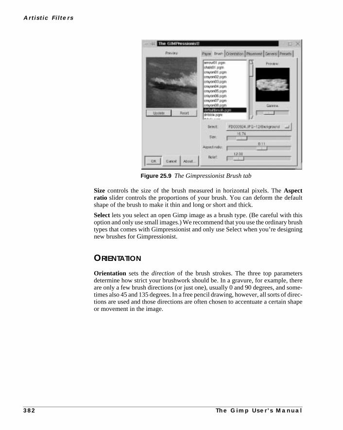
A r t i s t i c F i l t e r s
ult
thisrushning
rsere
ome-irec-shape
Size controls the size of the brush measured in horizontal pixels. TheAspectratio slider controls the proportions of your brush. You can deform the defashape of the brush to make it thin and long or short and thick.
Selectlets you select an open Gimp image as a brush type. (Be careful withoption and only use small images.) We recommend that you use the ordinary btypes that comes with Gimpressionist and only use Select when you’re designew brushes for Gimpressionist.
ORIENTATION
Orientation sets thedirection of the brush strokes. The three top parametedetermine how strict your brushwork should be. In a gravure, for example, thare only a few brush directions (or just one), usually 0 and 90 degrees, and stimes also 45 and 135 degrees. In a free pencil drawing, however, all sorts of dtions are used and those directions are often chosen to accentuate a certainor movement in the image.
Figure 25.9 The Gimpressionist Brush tab
3 8 2 T h e G i m p U s e r ’ s M a n u a l
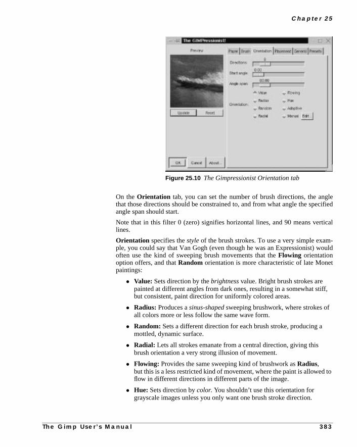
C h a p t e r 2 5
gleified
cal
-ould
t
iff,
to
On theOrientation tab, you can set the number of brush directions, the anthat those directions should be constrained to, and from what angle the specangle span should start.
Note that in this filter 0 (zero) signifies horizontal lines, and 90 means vertilines.
Orientation specifies thestyleof the brush strokes. To use a very simple example, you could say that Van Gogh (even though he was an Expressionist) woften use the kind of sweeping brush movements that theFlowing orientationoption offers, and thatRandom orientation is more characteristic of late Monepaintings:
• Value: Sets direction by thebrightness value. Bright brush strokes arepainted at different angles from dark ones, resulting in a somewhat stbut consistent, paint direction for uniformly colored areas.
• Radius: Produces asinus-shaped sweeping brushwork, where strokes ofall colors more or less follow the same wave form.
• Random: Sets a different direction for each brush stroke, producing amottled, dynamic surface.
• Radial: Lets all strokes emanate from a central direction, giving thisbrush orientation a very strong illusion of movement.
• Flowing: Provides the same sweeping kind of brushwork asRadius,but this is a less restricted kind of movement, where the paint is allowedflow in different directions in different parts of the image.
• Hue: Sets direction bycolor. You shouldn’t use this orientation forgrayscale images unless you only want one brush stroke direction.
Figure 25.10 The Gimpressionist Orientation tab
T h e G i m p U s e r ’ s M a n u a l 3 8 3

A r t i s t i c F i l t e r s
urns
theshare
gree
).
d out
n
• Adaptive: Is the most realistic-looking orientation mode. Thisorientation makes object-oriented brush strokes, where each shape isaccentuated by a certain stroke direction.
• Manual: Lets you make a really advanced painting. You can specify yoown brush stroke orientation by setting different angles and orientatiofor different parts of the artwork. Before you can apply Manualorientation, you mustedit the stroke directions. Press theEdit button,which will bring up theOrientation Map Editor .
THE ORIENTATION MAP EDITOR
As the name implies, you can specify how each brush stroke will be applied. InVectors window you can see the position and angle of your vectors (brustrokes). The currently active vector is highlighted in red, all other vectorsgrayed out. In thePreview window you’ll see how the different vectors willaffect the image field.
You can use several vectors, or just one as it fits your purpose. Toadda vector,press theAdd button. Todeletean unwanted vector, press theKill button. Tonavigate from one vector to another, press the “>>” and “<<” buttons.
To set the base angle of a vector, drag theAngle slider. To set an exact anglevalue, left-click on either side of the slide button to change the value one defor every click.
TheStrength slider controls the strength of the selected vector (brush stroke
The vector type can be set with the Type check buttons. The easiest way to finhow they work is to press them and look in thePreview window.
The Strength exp. slider controls the exponent of all vectors, i.e., you cachange the overall strength of all brush strokes.
Figure 25.11 TheOrientation Map Editor
3 8 4 T h e G i m p U s e r ’ s M a n u a l
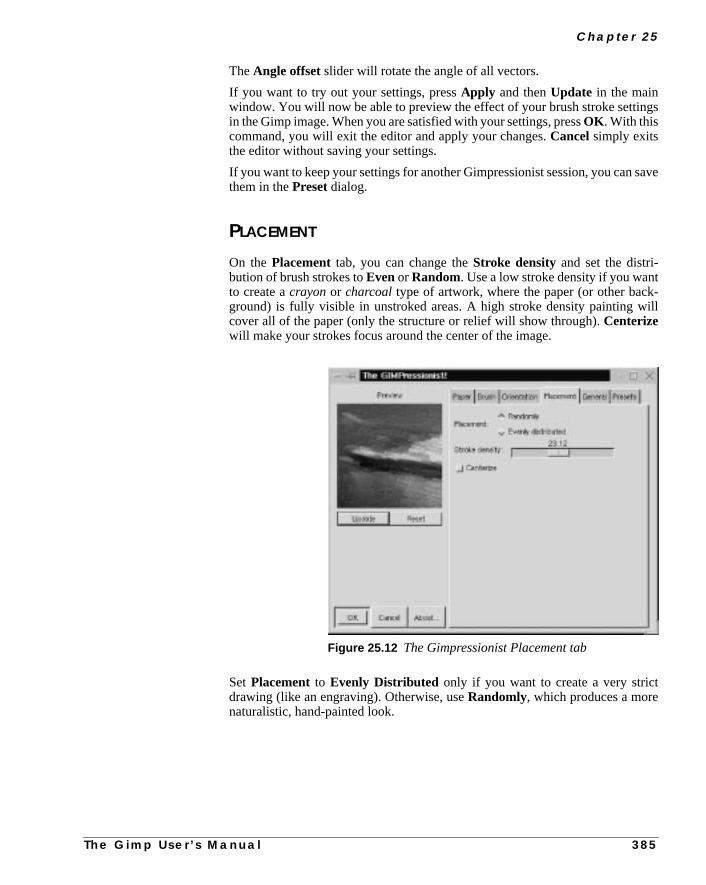
C h a p t e r 2 5
gs
save
-ill
TheAngle offset slider will rotate the angle of all vectors.
If you want to try out your settings, pressApply and thenUpdate in the mainwindow. You will now be able to preview the effect of your brush stroke settinin the Gimp image. When you are satisfied with your settings, pressOK . With thiscommand, you will exit the editor and apply your changes.Cancelsimply exitsthe editor without saving your settings.
If you want to keep your settings for another Gimpressionist session, you canthem in thePreset dialog.
PLACEMENT
On thePlacement tab, you can change theStroke density and set the distri-bution of brush strokes toEvenor Random. Use a low stroke density if you wantto create acrayonor charcoal type of artwork, where the paper (or other background) is fully visible in unstroked areas. A high stroke density painting wcover all of the paper (only the structure or relief will show through).Centerizewill make your strokes focus around the center of the image.
Set Placement to Evenly Distributed only if you want to create a very strictdrawing (like an engraving). Otherwise, useRandomly, which produces a morenaturalistic, hand-painted look.
Figure 25.12 The Gimpressionist Placement tab
T h e G i m p U s e r ’ s M a n u a l 3 8 5

A r t i s t i c F i l t e r s
sh
the
ld
ssb-
t can
GENERAL
On theGeneral tab, you can change the weight of the dark edge of the brustrokes, thus increasing the relief effect of thick oil paint. Note that if thePaintedgesbutton is left unchecked, the paint strokes will not cover the edges ofpainting; instead, it will leave a fringe of the background visible in that area.
TheBackground option allows you to choose what kind of background shoushow through at a low stroke density: theoriginal image, thepaper, a solidbackground color of your choice or atransparent background. You can alsomake your image tileable by checking theTileable button. This is a very handyoption if you’re creating a background for a web page.
PRESETS
The Presetstab contains a number of nice presets likeCubism, FlowerbedorWeave. You can also name and save your own settings in thePresets library.If you import Preset files into Gimp’s preset directory, don’t forget to preRefresh; otherwise, you will not see the new files. The preset directory will proably be called~/.gimp/gimpressionist/Presets or /usr/local/share/gimp/gimpressionist/Presets (site specific). Under thegim-pressionist directory you will also find theBrushes andPaper directo-ries where you can store additional brushes and papers that Gimpressionisuse.
Figure 25.13 The General tab
3 8 6 T h e G i m p U s e r ’ s M a n u a l

C h a p t e r 2 5
n-
s.w
MOSAIC
The Mosaic plug-in allows you to imitate everything from a stained glass widow to a ceramic mosaic floor.
PARAMETER SETTINGS
This plug-in has many parameters that let you control the final result: theTileSize and Tile Height, the Tile Spacing, and the Tile Neatness, whichcontrols the appearance of the stones.
Light Direction controls howlight will appear to shine on the mosaic edgeColor Variation adjusts how much the color is allowed to fluctuate. With a lovalue, the original color from the image will be preserved. If you set a lowNeat-nessvalue and a highColor Variation value, you will get a very abstractmosaic.
Figure 25.14 The Presets tab
T h e G i m p U s e r ’ s M a n u a l 3 8 7

A r t i s t i c F i l t e r s
for
will
ex-
nd
Tiling PrimitivesTiling Primitives determine the kind of mosaic tiles you want to use as a baseyour mosaic. If you choose aHexagonsshape from the Tiling Primitives andlower the neatness value, the hexagonal structure will fade, and the stoneslook more like natural stones.
OptionsAntialiasing produces smooth edges.Color Averaging creates a truemosaic. If this option is unchecked, the original picture will only get a mosaic tture. Pitted Surfaceswill produce a surface that looks old and used.FG/BGLighting controls edge color. If unchecked, Mosaic will use the foreground abackground colors from the toolbox.
Figure 25.15 The Mosaic dialog
Figure 25.16 Mosaic filterinvoked at the bottom-leftcorner
3 8 8 T h e G i m p U s e r ’ s M a n u a l

C h a p t e r 2 5
takeold.
ent.
me
olu-sedout
You can create very interesting surfaces with Mosaic. For example, you cana stone pattern and combine it with Mosaic to get something that looks like anstone floor, or use another combination, perhaps a cracked glass/windshield
NEWSPRINT
Newsprint createshalftone screen patternssimilar to a newspaper print. Youmay have used a similar Adobe Photoshop filter calledColor Halftone. Like manyGimp plug-ins, this filter is much more advanced than the Photoshop equival
TheNewsprint dialog includes a variety of parameters that control the outcoof the filter.
Note: The Input SPI (samples per inch, meaning pixels per inch or image restion) and Output LPI (lines per inch) sliders are provided so this filter can be uin the future as a ripper for imagesetters. Until that is possible, don’t bother abSPI or LPI and just use the Cell size slider.
Figure 25.17 Newsprintapplied on the left side
T h e G i m p U s e r ’ s M a n u a l 3 8 9

A r t i s t i c F i l t e r s
gepplyith
lacks the
sdots
SCREEN
In the screen control area, you can select whether to separate toRBG, CMYK orby Intensity.
Intensity will map black halftone dots to the brightness value in the RGB imaand place those dots on top of the original image. This is a rather neat trick to ahalftone likeness to a color image without having to simulate the colors wcoarse CMY rosettes.
TheRGB screening takes place in the red, green and blue channels, where bhalftone dots appear at the specified screen angles. Black in a channel signifieabsence of color, so the color is actually in the areasurroundingthe black dots.Because the RGB color system isadditive, the sum of the three RGB colors equalwhite, so the final effect of this screening is one of cyan, magenta and yellow
Figure 25.18 TheNewsprint dialog
3 9 0 T h e G i m p U s e r ’ s M a n u a l

C h a p t e r 2 5
mpen-
hitean-rlap
dentified.
onalourheseree
r
,rst
ots
on a white background. Of course, real printing issubtractiveand no process inksare red, green or blue, so this only works on the screen.
The CMYK screening simulates halftoning in CMYK channels (because Gidoes not yet support CMYK channels). The effect is the opposite of RGB screing, because CMYK is asubtractivecolor system. Here, the sum of C, M and Yequals black, and the “black spots” in the channels become holes where the wbackground shows through. The black K (key color) channel is an intensity chnel where the amount of black can be regulated against the black CMY ovewith theBlack Pullout slider.
The screen control area will display one channel control for each indepencolor channel. Each channel has its own spot function and screen angle specFor grayscale images, a smaller dialog with a singleGray channel will appear.
AngleThe default screen angle for the different color channels is set at the traditiprocess color print angles, which will produce a rosette of dots. If you want yimage to look as if it was taken from a newspaper, you should not change tvalues. However, if you just want to experiment with interesting patterns, feel fto change the screen angles as you see fit.
Spot FunctionsThere are several different spot functions to choose from:
• TheRound function produces circular dots.
• TheLine function can be used for special effects at 90 or 0 degrees fograyscale images (compare it to theright-click|Filters|Distorts| Engrave filter) or at crossing “fishnet drawing” anglesfor RGB images.
• TheDiamond spot is symmetrical and therefore its own inverse. At 50%it forms a checkerboard pattern with all four corners touching for the fitime.
• TheEuclidean spot function is probably the most common spotfunction, because it is both symmetrical and tends to produce round dmost of the time.
• ThePostScript diamond function grows from a small round spot to adiamond, and then back to an inverted round spot.
T h e G i m p U s e r ’ s M a n u a l 3 9 1

A r t i s t i c F i l t e r s
had
elpe is
oreugh
t-r
OILIFY
As you might guess,Oilify makes your image look like an oil painting.MaskSizecontrols the outcome. A high value gives the image less detail (as if youused a larger brush).
Tip: This tool is nice to use with several layers. You can also use this filter to hyou select intricate objects by running it on a duplicate layer; a simplified shapmuch easier to select.
VAN GOGH (LIC)Van Gogh can be used to blur an image or to add texture. This plug-in has min common with the texture or displace filters than the artistic ones, even thoyou can achieve artistic results with it.
• To create ablur , checkConvolve with source image beforeapplying the filter.
• To create atexture, checkConvolve with white noise.
GENERAL PARAMETERS
Whether you want to make a pattern or a blur effect, you must first create amapimage. Effect channel determines which HSV channel should be used (brighness is generally best).Effect operator controls the direction of the pattern o
Figure 25.19 Oilify invoked atthe bottom right in the image
3 9 2 T h e G i m p U s e r ’ s M a n u a l

C h a p t e r 2 5
f theove-
vice
the
alsoangen-
blur. Derivative sets the direction opposite ofGradient. If your map image hasa certain direction, the effect operators work much the same way as theFlip toolin the toolbox.
BLUR
The advantage of this filter is that the map image determines the direction oblur effect, which means that you can adapt a gradient to create variation, mment and a sense of direction in blurring. Aradial gradient creates a circular blurmovement, ahorizontal linear gradient (like dragging left to right) puts anemphasis on vertical lines in the image because it blurs horizontal lines, andversa.
A solid color object in the map image doesn’t create a blur effect (except forantialiased edges); you must use some sort ofgradient in the areas you wish toblur. You should probably use the default settings, with the exception ofFilterlength, which controls the strength or depth of the blur, and in some measureIntegration steps. Use a black/white gradient map and nothing else (you cuse all sorts of image maps, but in most cases it won’t accomplish more than aeral blur over the entire image).
Figure 25.20 The VanGogh (LIC) dialog
T h e G i m p U s e r ’ s M a n u a l 3 9 3

A r t i s t i c F i l t e r s
Target image
Vertical MapHorizontal Map Square Map Radial Map
Vertical PatternHorizontalPattern
ShapeburstPattern
Radial Pattern
Filter Length, Blur
Vertical BlurHorizontal Blur Shapeburst Blur
DerivativeShapeburst Blur
Radial Blur
Figure 25.21 These examples illustrate the effect on atarget grid-line image using different maps with blur ortexture setting
The Derivative Shapeburst illustration shows the resultof using Derivative instead of Gradient Effect Operator.The Filter Length, Blur image shows what the RadialBlur image would look like using a higher Filter Lengthvalue.
3 9 4 T h e G i m p U s e r ’ s M a n u a l

C h a p t e r 2 5
edinkage,er
than
ce).
lylarge
of
s.rte a
TEXTURE
Van Gogh is especially good for making patterns that look like woven or knitttextiles or fabrics. Use a target image with a solid color or a color pattern you thwould fit your texture. Use a grayscale gradient or blurred mask as a map imset Integration Steps a bit higher than default and experiment with the othsettings to get the sort of texture you want.
When you use this filter as a texture maker, the settings are more importantwhen you use it for blurring:
• Max/Min Value: Controls contrast. If the Max/Min range is large,contrast is low. The contrast increases when you shrink the interval.Thissetting does not affect blur.
• Integration Steps: Controls how much the map gradient is allowed toinfluence the shape of the pattern (a large integration = a large influenDon’t set this parameter too low for blur; the default is probably fine.
• Noise Magnitude: Controls the amount and size ofrandom noise(which breaks up the regularity of the pattern). Low values produce finegrained surfaces (sand), and high values produce coarser materials (bumps and holes).These values do not affect blur.
• Filter Length: Controls depth just like theright-click|Filters|Distorts| Emboss filter. Low filter length gives you asmooth surface; high filter length provides a rough surface. This valuecontrols the strength of the blur (compare the two images at the bottomFigure 25.21 —Radial Blur andFilter Length, Blur — to appreciate thedifference between low and high filter length)
Creating A Burlap Cloth TextureRun the Van Gogh filtertwiceon awhite image to produce two separate imageBoth times, checkWhite Noise (for pattern), select a quite small interval foMax/Min and put the other sliders somewhere in the middle (higher to creacoarser fabric). Use adiagonal linear gradient as the map.
SetGradient the first time andDerivative the second time (which will invertthe direction of the pattern). Paste thesecondresulting image to a new layer in thefirst resulting image, and setLighten Only mode (or another suitable mode).
Figure 25.22 Cloth texture
T h e G i m p U s e r ’ s M a n u a l 3 9 5

A r t i s t i c F i l t e r s
e asrp
.
oresizearta
war-
WARP
Warp can produce effects that are a lot like the patterns you might have mada child with a spoon in a bowl of thick cream and juicy berries. To make Wawork properly, you’ll need aDisplacement map (see the explanation of“Displace” on page 542 to get a good understanding of displacement maps)
For example, to create juicy curls, you should use theSolid Noise filter(right-click|Filters| Render | Solid Noise ) for a displacement map.
The more detail and small turbulences you have in the map image, the msmaller and frizzier curls you’ll get. Make sure that the map image is the sameas the image you want to work the filter on. If you only want to warp a small pof the image, you caneraseor cut part of the map image, and only leave an arethat is about the same size and shape as the area you want towarp in the targetimage. When you want to specify a more exact position, size and shape of thepable area, use a magnitude map instead.
Figure 25.23 Warp
Figure 25.24 TheWarp dialog
3 9 6 T h e G i m p U s e r ’ s M a n u a l

C h a p t e r 2 5
t
e
hey
ws
bearp(or
of
MAIN OPTIONS
• Step Size: Controls the amount orstrength of the filter. The value youset here affects the image for every iteration, or warp step, you make.
• Iterations: Sets the number of times the filter should repeat the effect.
• On Edges:Refers to the way the plug-in deals with background color athe distorted edges (see “Displace” on page 542).
SECONDARY OPTIONS
• Dither Size: Causes pixels to displace randomly, thus decomposing thimage. A moderate Dither Size just makes the warp curls look moregrainy. Larger values scale from fuzzy particle clouds to totaldisintegration of the image.
• Rotation Angle: Determines what the “curls” will look like. A 90-degree rotation, the default setting, makes them look like smallwhirlpools. A 0-degree rotation looks more like the kind of soliddistortion you’d see through a bathroom window. Other angles arecombinations of these two, more or less so depending on how close tare.
• Substeps:Increases calculation time for each flow step. Raising thenumber of substeps gives a slight improvement in detail, but it also slodown the process.
• Magnitude Map: A more subtle way of controlling what parts of theimage should be warped and by how much. The Magnitude map shoulda grayscale image, where areas you do not wish to affect are black. Wmagnitude is determined by a brightness scale. White represents 100%normal warp), black stands for no warp at all and the different shadesgray weaken the warp effect.
Figure 25.25 This example shows the warped image, and the map imagesneeded to achieve the warp effect
Warped Image Magnitude Map Displacement Map
T h e G i m p U s e r ’ s M a n u a l 3 9 7

A r t i s t i c F i l t e r s
ere,e dis-
ch
s andf thes a
OTHER OPTIONS
Besides the Warp displacement map, you can add aGradient displacementmap. This map will not displace in the curly warps you have seen before. Hdisplacement depends on the direction of the gradual transition that makes thtortion straight and angular. TheGradient Scalesets the amount of influencethe gradient map should have.
You can also displace along a fixed direction by using aVector map. This optionlets you displace a chosen map one step per iteration in a certain direction.VectorMagnitude determines by how many pixels the image should move for eaiteration, and the direction is specified in theAngle swatch. A Vector map issomething in between a Displace and a Magnitude map. It protects black areathe rest of the image moves along the vector direction. The smoothness ostretch is determined by the number of pixels specified. A low value givesmooth disfigurement of the image.
Displacement Map As Vector Map
As Gradient Map As Normal Warp Map
Figure 25.26 These examples illustratethe result of using thesame map withdifferent options
3 9 8 T h e G i m p U s e r ’ s M a n u a l


C H A P T E R
26 Blur FiltersGimp provides many ways to create blur effects. Thischapter tells you how you can learn what filter to useand how to get the kind of blur you want.
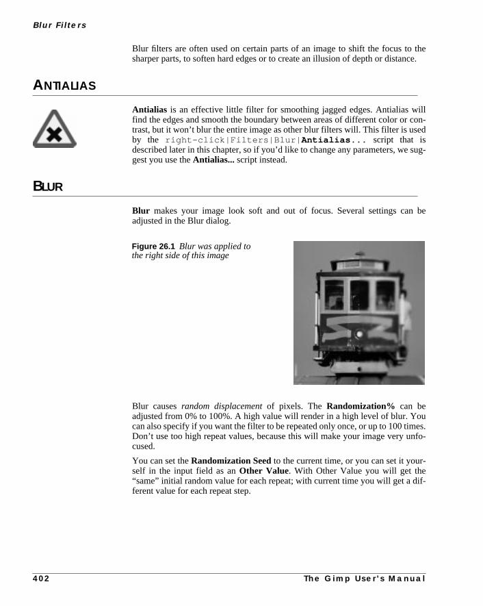
B l u r F i l t e r s
thece.
llcon-d
sug-
be
ues.
nfo-
-
if-
Blur filters are often used on certain parts of an image to shift the focus tosharper parts, to soften hard edges or to create an illusion of depth or distan
ANTIALIAS
Antialias is an effective little filter for smoothing jagged edges. Antialias wifind the edges and smooth the boundary between areas of different color ortrast, but it won’t blur the entire image as other blur filters will. This filter is useby the right-click|Filters|Blur| Antialias... script that isdescribed later in this chapter, so if you’d like to change any parameters, wegest you use theAntialias... script instead.
BLUR
Blur makes your image look soft and out of focus. Several settings canadjusted in the Blur dialog.
Blur causesrandom displacementof pixels. The Randomization% can beadjusted from 0% to 100%. A high value will render in a high level of blur. Yocan also specify if you want the filter to be repeated only once, or up to 100 timDon’t use too high repeat values, because this will make your image very ucused.
You can set theRandomization Seedto the current time, or you can set it yourself in the input field as anOther Value. With Other Value you will get the“same” initial random value for each repeat; with current time you will get a dferent value for each repeat step.
Figure 26.1 Blur was applied tothe right side of this image
4 0 2 T h e G i m p U s e r ’ s M a n u a l
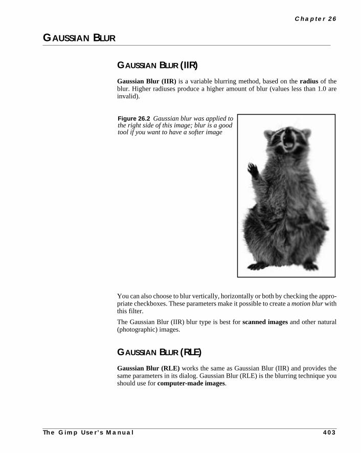
C h a p t e r 2 6
are
ro-
heyou
GAUSSIAN BLUR
GAUSSIAN BLUR (IIR)
Gaussian Blur (IIR) is a variable blurring method, based on theradius of theblur. Higher radiuses produce a higher amount of blur (values less than 1.0invalid).
You can also choose to blur vertically, horizontally or both by checking the apppriate checkboxes. These parameters make it possible to create amotion blurwiththis filter.
The Gaussian Blur (IIR) blur type is best forscanned imagesand other natural(photographic) images.
GAUSSIAN BLUR (RLE)
Gaussian Blur (RLE) works the same as Gaussian Blur (IIR) and provides tsame parameters in its dialog. Gaussian Blur (RLE) is the blurring techniqueshould use forcomputer-made images.
Figure 26.2 Gaussian blur was applied tothe right side of this image; blur is a goodtool if you want to have a softer image
T h e G i m p U s e r ’ s M a n u a l 4 0 3

B l u r F i l t e r s
MOTION BLUR
Motion Blur simulates a snapshot of a moving object.
LINEAR MOTION BLUR
If you check theLinear radio button in theBlur type field, the image will lookas if the object was movingbesideyou. TheAngle slider sets thedirection ofthe motion and theLength slider controls thespeedof the motion (the moreLength the higher the speed).
Figure 26.3 The Motion Blur dialog
Figure 26.4 Linear MotionBlur was applied to the upperparts of the sprinter toaccentuate the impression ofmotion and speed
4 0 4 T h e G i m p U s e r ’ s M a n u a l

C h a p t e r 2 6
r
r
e
RADIAL MOTION BLUR
If you check theRadial Blur type radio button, the image or selection will appeato berocking or spinning in front of you.
In this case,Angle determines the amount of radial motion. A high value foAngle will make the image spin.Length determines howfast the object appearsto be rocking/spinning.
ZOOM MOTION BLUR
If you check theZoom Blur type radio button, the objects in the middle of thimage will look as if they are movingtowardsor awayfrom you. Here,Lengthis the apparent speed at which the object is travelling.Angle seems to have noimpact on this blur mode.
Figure 0.1 The upper gear has been blurred withRadial motion blur, which makes the gear appear tobe in movement, while the chain and lower gearremain still. This is naturally impossible in real life,but Gimp makes the illusion seem real enough.
Figure 0.1 We have blurred the surroundings of therunning man (inverted selection of the man) with theZoom blur, making him seem to be flying toward us atthe speed of light
T h e G i m p U s e r ’ s M a n u a l 4 0 5

B l u r F i l t e r s
ve
.
ed.rwill
teduce
theax
henthen
ge.sed
ds.
PIXELIZE
Pixelizemakes your image look as if it was made of really large pixels. You hato set the new pixel size. In other words, aPixel Width of 3 makes an area madeup of a 3x3 pixel block look like a single large pixel.
SELECTIVE GAUSSIAN BLUR
Selective Gaussian Blur is very useful for removingnoise from scannedimages. It works by adding blur to the parts of the image where focus is low
TheMax Delta parameter controls the size of the image area that will be blurrA high value (>70) will blur larger areas, while low values (<40) will only blusmall portions of the image. This means that using a high value for Max Deltacause more details to be blurred.
The Radius parameter controls the amount of blur that is applied to selecparts. High values (>7) produce a high level of blur, and low values (<4) proda weaker blur effect.
When you use this filter to remove noise, we recommend that you start withdefault values (5, 50). If the default values prove too strong, then lower the MDelta parameter until you are satisfied. If this still doesn’t remove your noise, traise the blur Radius. If a higher blur level should reduce details in the image,lower the Max Delta value.
Another application for this filter is for accentuating the focused part of the imaSince Selective Gaussian Blur removes noise, it will also smooth less focuparts of the image, thus addingdepth to the image, and highlighting the focuseparts. This function is ideal when you work with amateur portrait photograph
Figure 26.5 Pixelized secret agent
4 0 6 T h e G i m p U s e r ’ s M a n u a l

C h a p t e r 2 6
ound
lend-
and
e
ing
TILEABLE BLUR
Tileable Blur is an excellent tool for softening the tile seams in images ywant to use in tiled backgrounds. Tileable Blur compares the pixels that will eup next to each other when the image is tiled, and compensates for this by bing/blurring those edges as if they had been adjacent.
The Blur Vertical/Horizontal and Radius functions are the same asdescribed in theGaussian Blur filter. The RLE and IIR options are for com-puter-generated and photographic images, respectively, just as withGaussianBlur RLE/IIR .
To avoid blurring the entire image, useright-click|Select| Featherto select the important parts of the image (the parts that you don’t want to blur)right-click|Select| Invert the selection before you apply the filter.
Note that Tileable Blur is ascript, so it can’t be reversed with Undo.
VARIABLE BLUR
Variable Blur is much like ordinary blur, but it allows you to regulate thamount of blur by adjusting theMask Size. A large Mask Size will result in ahigh amount of blur, and vice versa.
Before After
Figure 26.6 Selective Gaussian Blur before and after; notice the background (table),which has a high degree of noise before but not after; this is a very useful tool for smoothout noise and still getting a high level of detail
T h e G i m p U s e r ’ s M a n u a l 4 0 7

B l u r F i l t e r s
canefaultof 1/
otht
ANTIALIAS...This Antialias... script allows you to fine-tune thecontrast in the softened(antialiased) border. The antialiasing border is always 2 pixels wide, but youset a preference for what the contrast should be between those pixels. The dvalue (0.33333) produces a normal antialias border, with an even distribution3 of the new color in the first pixel and 2/3 in the second pixel.
A lower value results in low contrast between the two pixels because they’ll bget a similarintermediatecolor, while high values will increase the contrasbetween the pixels. This script uses theAntialias filter described in the begin-ning of this chapter.
Figure 26.7 Variable Blur was appliedto the left part of the image
Figure 26.8 Applying antialias to a blocky edge will produce a smootheroutput
Before After
4 0 8 T h e G i m p U s e r ’ s M a n u a l


C H A P T E R
27 Color FiltersWelcome to the color darkroom! With these filtersyou can achieve effects that you would create in adarkroom: changing colors, masking colors andmore.

C o l o r F i l t e r s
hes.the
r ase
ADJUST FGRD. - BKGRD.Adjust Fgrd. - Bkgrd is a simplecolor map function. The pixels in the imagewill be mapped against the toolbox foreground and background color swatcThe darkest pixels in the image will be mapped to the foreground color, andlightest to the background color in the toolbox. Also, pixels with the same colothe foreground will be mapped toblack, and pixels with the same color as thbackground will be mapped towhite.
ALIEN MAP
Alien Map applies trigonometrical functions toRGB channels.
FUNCTIONS
The Cosine FunctionLet’s take theRedchannel and see what we can do with it. First, setGreenandBlue to None (i.e., Linear), setPhasedisplacement to 0.00 andFrequency to1.00 for all channels. Last, uncheck allInversion buttons.
Figure 27.1 The right part of the imagewas mapped with Adjust Fgrd-Bkgrd
4 1 2 T h e G i m p U s e r ’ s M a n u a l

C h a p t e r 2 7
If you now checkCosine in the Red channel, the image will get a lot redder.
Figure 27.2 The Alien Map dialog
Figure 27.3 The Cosine function applied to thered channel will boost red middle values andsubdue high values for red
T h e G i m p U s e r ’ s M a n u a l 4 1 3

C o l o r F i l t e r s
ou
ed
pliesht-the
arkdium/s arereaslues
Why? Well, the original picture contains a lot of medium red skintones. As ycan see in Figure 27.3. Cosine willboostthose “middle” red values.Rememberthat medium gray areas also contain middle values of red.You may also noticethat the parts withhigh value for red have been subdued. Maximal values for rare often found inwhite/brightareas, which assume acyan tint when the red isremoved.
What happens if we set all three channels to Cosine? The same principle aphere. Middle tones getboosted, which means that those areas turn brighter. Brigareas turn dark, because those areas aresubdued. Dark areas stay dark, and if a certain color is very saturated, that color will either turn dark or change into one ofprimary colors: blue, red or green.
The Sine FunctionIf you checkSineyou’ll notice that the image will get considerablylessred. Thisis becauseSinedoes not change middle RGB values much. Note that really dparts such as the hair and eyes have become more red, while most of the melow red values (the background) have been subdued. Medium/high red valueboosted (the face), as are the bright parts of the T-shirt, while the truly white ashift toward cyan. Sine in all channels results in higher contrast in medium vaand lower contrast in bright/dark areas.
Figure 27.4 The Cosine function applied to allthree channels.
4 1 4 T h e G i m p U s e r ’ s M a n u a l

C h a p t e r 2 7
om 0
t
ne
the
Figure 27.7 shows a cosine and a sine wave over the Red channel interval frto 255. With acosinefunction, red color with a value of 128 (medium red) will bemapped to 255 (maximum red). With asinefunction, medium red tones can gevery different red values depending on what side of 128 they are on.
PARAMETERS
Inversion 1 will invert the color values before the Alien Map function has beeapplied.Inversion 2 will invert the colors after Alien Map has applied the sinor cosine function.
Color intensity is easy to understand; with the RGB sliders you can adjustintensity of each channel. ButPhase displacementand Frequency are per-haps a bit harder to understand.
Figure 27.5 Sine in thered channel
Figure 27.6 Sine in allthree channels
Figure 27.7 The Cosine andSine curves show how values in theoriginal image will be mapped
T h e G i m p U s e r ’ s M a n u a l
4 1 5
C o l o r F i l t e r s
.
ve
thee
Frequency
Lets start withfrequency, using the settings of the Sine example in Figure 27.5Changing the frequency of a sine function can produce dramatic effects.
If you set the frequency to 0.5, as in Figure 27.8, you can only fit ahalf sine waveover the 0 to 255 interval. This will make the red values follow the normal curpretty well, so this will only increase thecontrast in the image. If, on the otherhand, you set the frequency to 4 or more, you will fit four sine waves overinterval, which will map the maximum value to four different red values in thimage.
Figure 27.8 Half frequency
Figure 27.9 Quad frequency
4 1 6
T h e G i m p U s e r ’ s M a n u a l
C h a p t e r 2 7
autheini-
Phase DisplacementIf you change thePhase displacementslider, you will drag the sine waveside-ways in the 0 to 255 interval. This naturally will affect the mapping so thathigher value will be mapped to 255 if you slide it in a positive direction. If yoslide it in a negative direction, a lower value will be mapped to 255. Notice thateffect is circular because the outcome is the same for both maximum and mmum values.
Figure 27.10 In this example, the Phase wasdisplaced to 3.00 in the positive direction
Figure 27.11 These images show the effect of the cosine function, using different parameter settings
Original Cosine Frequency = 2 Phase disp = 1.25
T h e G i m p U s e r ’ s M a n u a l 4 1 7

C o l o r F i l t e r s
s into
en-singore
60
ALIEN MAP2Alien Map2 is also based ontrigonometricalfunctions, but it is more versatilethan theAlien Map filter. The difference is that you can switch betweenRGBandHSV (HSL) space. Otherwise, the parameters in this filter are the same aAlien Map, so we recommend that you first read “Alien Map” on page 412,understand Alien Map2.
FREQUENCY AND PHASE
In RGB space, each color channel can be adjusted by tuning theFrequencyandPhase displacement angle. Frequencies around 0.3 to 0.7 provide a curvthat is similar to the linear function (original image), only darker or with more cotrast (see Figure 27.8). As you raise the frequency level, you’ll get an increavariation in pixel transformation, meaning that the image will get more and m“alien” (see Figure 27.9).
The phase change will alter the value transformations. You’ll find that 0 and 3degrees are the same as asine function and 90 is the same as acosine func-tion, while 180 inverts sine and 270 inverts cosine.
Figure 27.13 The top leaf wasmapped to autumn colors withAlienMap2
Figure 27.12 The AlienMap2 dialog
4 1 8
T h e G i m p U s e r ’ s M a n u a l
C h a p t e r 2 7
ill
the
rderbor-the
alue
ress
HSV MANIPULATION
In HSV space, the most notable difference is theHue channel. The sine curve fol-lows the color distribution of the HSV color circle, and a change in frequency wproduce psychedelic results. TheSaturation andValue (Luminance) channelscan be manipulated in the same manner.
BORDER AVERAGE
The Border Average tool is used to calculate thebackground color of webpages. The idea is to find a web page color that differs as little as possible fromedge pixels in your image.
Use Border Average to calculate the most common (mean) color in a boaround the current selection, or an image if there is no present selection. Theder is an imaginary image border that is X pixels wide. Set the border width inBorder Size Thicknessfield. The Bucket Size parameter controls the num-ber of colors that are used to calculate the average color. A high Bucket Size vgives you better precision in these calculations.
COLOR MAPPING
The Color Mapping filter is a plaincolor map filter. You can map two colorsin your image to two new colors. The interface is simple to understand. Just ptheFrom andTo buttons to set the colors that you want to swap.
Figure 27.14 This illustration showshow a sine curve can be transformedwith different phase displacement angles
T h e G i m p U s e r ’ s M a n u a l 4 1 9

C o l o r F i l t e r s
COLOR EXCHANGE
Color Exchangeis a lot like theColormap Rotation filter (see “Colormap Rota-tion” on page 422) but it is simpler and faster.
Define the color to exchange (theFrom color) by setting the slider for eachRGB channel and a threshold fuzziness as you did inright-click|Select| By Color to define the color range that will be affected. TheTocolor slidebars specify the RGB values of the new color.
Figure 27.15 The right side of thisimage was mapped with Color Mapping
Figure 27.16 The bottom-leftpart of this image was alteredwith Color Exchange
4 2 0 T h e G i m p U s e r ’ s M a n u a l

C h a p t e r 2 7
rs,olor
Tip: Always keep the Color Select dialog up as you’re adjusting the RGB slideso that you can choose a color there and insert the given RGB values in the CExchange dialog.
Figure 27.17 The ColorExchange dialog
T h e G i m p U s e r ’ s M a n u a l 4 2 1

C o l o r F i l t e r s
ss.by
te
ap
.
COLORIFY
Colorify makes your image look like it is being viewed through colored glaPredefined colors are provided, but you can also set a color of your choiceclicking on theCustom Color swatch.
COLORMAP ROTATION
Colormap Rotation lets you exchange one color interval for another.
THE MAIN TAB
In theFrom andTo color circles, define the color range that you want to rotafrom and the color range you want to rotate to. By default the range is goingcoun-terclockwise, so if you define a range that you want to rotate, the rotation will myour pointers in theFrom andTo color circles. If one of the fields is switched toclockwise, the first pointer in a field will map the second pointer in the other field
Figure 27.18 The left part of theimage has been treated with Colorify
4 2 2 T h e G i m p U s e r ’ s M a n u a l

C h a p t e r 2 7
enta
tire
ExampleIn theFrom circle, select a range from cyan to magenta and selectcounterclock-wise. In theTo field, select the same range (butclockwise). Then, all cyan colorswill be rotated to magenta, and vice versa.
If you press theSwitch Order of Arrows button, the range will beinverted.When, as in the example above, your selection range goes from cyan to magover blue, Switch Order of Arrows will change the selection range to go frommagenta to cyan over red and green.TheSelect The Entire Range buttonwill select the whole range. Colormap Rotation makes it easy to rotate an encolor range to another shade or color range.
Figure 27.19 The Colormap Rotation dialog
T h e G i m p U s e r ’ s M a n u a l 4 2 3

C o l o r F i l t e r s
iso beshould
f the
k
ess
e
THE MISC TAB
What Is Gray?In the Misc tab, you can specify how to treat gray “colors.” By default, grayconsidered colorless and is not affected by the rotation. But gray can alsdefined as other shades, such as a very washed-out shade of green, andtherefore by definition be affected by the rotation.
How saturated a color has to be for it to be affected depends on the settings oTreat As This or Change To This parameters.
Gray SettingsSo let’s find out how to define what gray is, and how to deal with it.
The fieldWhat is Gray? is where you specify what saturation range you thinshould be considered “gray.” You define this in aSaturation scalefrom 0 to 1(pure gray is 0).
Zero saturation is often too narrow, so you will probably have to set gray to lthan or equal to 0.1 or 0.2. As you set this value, the circle in theGray color circlewill expand and cover more saturation values.
Original Rotated
Figure 27.20 The lettuce has turned red instead of green — the samgoes for all green parts of the image
4 2 4 T h e G i m p U s e r ’ s M a n u a l

C h a p t e r 2 7
nt
cle,.
ave
he
is-on-
ta-
The radio buttonsTreat As This and Change To This determine what youwant to do with the gray areas you defined in the What is Gray field.
If you’ve checked Treat As This, you’re telling the plug-in what color you wagrayto be like. You do this bypaningthe little circle cursor in the Gray color cir-cle. For example, you can drag the define circle to the red part of the color cirand all gray shades will be treated as red when you perform a color rotation
If you check Change To This, all gray shades will be changed to the color you hselected within the gray define circle.
Other ParametersYou can also select what kind ofUnits you want to use —Radians, Radiand/PI or Degrees— when you view and drag the pointers in the rotation dialog.TPreview can be set toEntire Image, Selection or Context.
Context is a smart preview option if you have a selection. Instead of just dplaying the selection, the Context option will let you see the selection in its ctext, as if you hadzoomed outa little bit from the selection. Check thePreviewas you Dragcheckbox if you want the preview to change as you drag in the rotion dialog.
Figure 27.21 The Misc tab
T h e G i m p U s e r ’ s M a n u a l 4 2 5

C o l o r F i l t e r s
atinguraler
r Sat-HSVsing
FILTER PACK
Filter Pack is a real darkroom tool in which you can do most of the things thyou would do in a real lab. Although you can perform all of these functions usother tools in Gimp and maybe even with better precision, this tool has a natinterface. It’s perfect for fixing up old and faded pictures, or for correcting othkinds of color problems.
SELECT PIXELS BY AND AFFECTED RANGE
First, in theAffected Rangefield, decide whatbrightness values you want towork with: Shadows, Midtonesor Highlights. By selecting Shadows, only thedarkest pixels in the image will be affected by the Filter Pack operations.
The Select Pixels ByHue, Saturation or Value, buttons determine what HSVchannel the selected range should affect. The default setting isValue (bright-ness), but there are occasions where you may wish to operate on the Hue ouration channels. To illustrate this point, we have decomposed an image toin Figure 27.22. Figure 27.23 shows how an image can be manipulated uSelect Pixels By Hue.
Figure 27.22 These pictures show theoriginal imagedecomposed to HSV;as you see, selectingpixels by value, hueor saturation willselect totally differentparts of the image
Hue Value Saturation
Figure 27.23 The fair and the darkboys were created from the same imageby selecting Shadows in the AffectedRange field, and then selecting pixels byHue; this way, only the face was affectedby color and value changes
The blond hair was made by selectingpixels by Value, and making those areaslighter in the Value Window
4 2 6 T h e G i m p U s e r ’ s M a n u a l
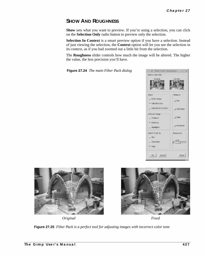
C h a p t e r 2 7
ick
ad
er
SHOW AND ROUGHNESS
Show sets what you want to preview. If you’re using a selection, you can clon theSelection Only radio button to preview only the selection.
Selection In Context is a smart preview option if you have a selection. Insteof just viewing the selection, theContext option will let you see the selection inits context, as if you had zoomed out a little bit from the selection.
TheRoughnessslider controls how much the image will be altered. The highthe value, the less precision you’ll have.
Figure 27.24 The main Filter Pack dialog
Figure 27.25 Filter Pack is a perfect tool for adjusting images with incorrect color tone
Original Fixed
T h e G i m p U s e r ’ s M a n u a l 4 2 7

C o l o r F i l t e r s
in
e of
If
. Ation.
WINDOWS
The Windows settings determine what kind of values you are interestedchanging (Hue, Saturation, Value or Advanced) and therefore want to view.
• Hue lets you change thecolor of the image. If you want your image tolook a bit more blue, just press the blue preview in the Hue window.
• Value lets you change the amount oflight in the image.
• Saturation lets you alter the colordullness/loudness.
Advanced OptionsIn Advanced Options,you can set thePreview size (useful if you have a largescreen).
You can also check thePixel Selection Menu, which lets you select the HSVvalue that you want to change. The pointers in the curve let you alter the rangshadows, midtones and highlights in a brightness scale from 0 to 255.
The slideralters thesmoothnessof the transition from one shade to another.you set it to zero, only the selected range(shadows, midtones or highlights)willbe affected by your interaction. If you set it to 1, every range will be affectedvalue in the middle is the most appropriate choice to create a smooth transi
Hue Value
Saturation
Figure 27.26 Filter Pack’s HSV Variations windows
4 2 8 T h e G i m p U s e r ’ s M a n u a l

C h a p t e r 2 7
ingan-
el.the
r bylog.
inguldr.
FS-DITHER
FS-Dither is used for preparing images that are going to beindexed (such asGIF images). This filter was created as an alternative to Gimp’s built-in Ditherfunction, which is less advanced. With this filter, you can select which color chnel to dither, which gives you a better control of the dithering process.
OPTIONS AND ADVICE
The Number of Shadesoption refers to the number of colors in each channIf your image is a grayscale, you should set the same amount of colors inIndex dialog as you did inNo. of Shades.
If your image is an RGB image, you should multiply the No. of Shades numbethree, and add two shades for white and black. Set this number in the Index dia
Remember to index againstOptimal palette in the Index dialog, because that’swhat FS-Dither uses for a palette when it dithers. If you index against somethelse, the FS-Dither will not work as well as it is supposed to. Naturally, you shouncheck theDither option in the Index dialog when you have applied FS-Dithe
Figure 27.27 The Advanced Filter Pack Options dialog
T h e G i m p U s e r ’ s M a n u a l 4 2 9

C o l o r F i l t e r s
three
tept
euet
ou
To get a better view of how much betterFS-Dither is than Gimp’s dither, takea look at the reference images below. Both gradients have been dithered withshades.
GRADIENT MAP
Gradient Map allows you to map the image against theactive gradient in theGradient Editor . The lightest pixel in the image will get the color on the righin the Gradient Editor, and the darkest pixel will get the color on the left (excfor transparent areas).
Before applying this filter, you’ll want to open up the Gradient Editorright-click|Dialogs| Gradient Editor or File|Dialogs| Gradi-ent Editor and select a gradient.
Think of the effects of Gradient Map as mapping theluminosity (Value) of yourimage against thegradient in the Gradient Editor. Say that in your image, thluminosity stretches from 50 (dark) to 235 (light). Pixels with a luminosity valof 50 will get the left end color, pixels with a luminosity of 51 will get the nexcolor to the right (from the left end) in the Gradient Editor and so on until yreach 235, which will get the right end color.
Figure 27.28 The differencebetween Gimp’sbuilt-in dither andFS-Dithering Original
Gimp’s dither
FS-Dither
4 3 0 T h e G i m p U s e r ’ s M a n u a l
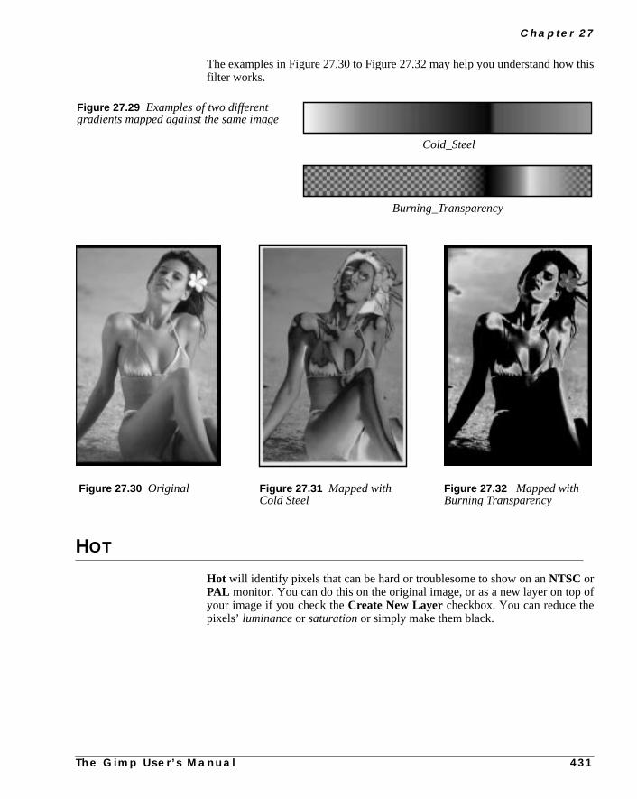
C h a p t e r 2 7
this
of
The examples in Figure 27.30 to Figure 27.32 may help you understand howfilter works.
HOT
Hot will identify pixels that can be hard or troublesome to show on anNTSC orPAL monitor. You can do this on the original image, or as a new layer on topyour image if you check theCreate New Layercheckbox. You can reduce thepixels’ luminance or saturation or simply make them black.
Figure 27.30 Original Figure 27.31 Mapped withCold Steel
Figure 27.32 Mapped withBurning Transparency
Cold_Steel
Burning_Transparency
Figure 27.29 Examples of two differentgradients mapped against the same image
T h e G i m p U s e r ’ s M a n u a l
4 3 1
C o l o r F i l t e r s
eb,
pureMax
seadyto
oseillthan
anwn-feelf the
oth!
It’s generally a good idea to use this filter when you publish images on the wbut the obvious drawback is that different surfers use different monitors.
MAX RGBMax RGB goes through the pixels in the image, detects whichRGB channel hasthe highest or lowest value and maps each pixel to either pure red (255,0,0),green (0,255,0) or pure blue (0,0,255). Figure 27.34 displays the effects ofRGB.
If you check theHold the maximal channelsradio button, you select bymax-imal value. Ifcyan, magentaor yellow values exist in your image, those colorwill remain even after the filter has been applied, because those colors alrhave maximal values for two RGB colors (the filter doesn’t know which colorchoose).
If you checkHold the minimal channels you select byminimumvalue. Withthis button checked, process colors will not show, because the filter will chothe lowest value, which is 0 for one of the RGB channels. Black and white wremain in both cases, because they have no RGB value that is lower or higheranother.
QUANTIZE
The effect ofQuantize is similar to making anIndexed image from anRGBimage, but now you can stay in RGB space.
Use Quantize when you want to selectively reduce the number of colors inimage (for example, when you prepare to make a small GIF that’s fast to doload). Because you’re still in RGB space, you can select an area where youcolor is less important and Quantize those colors. Then, you can keep more o“important colors” when you index the image.
You can choose between two different color spaces:CIE or RGB. You can checkPrincipal Quantization if you want the filter to Quantize to slightly differentcolors. Which method to use depends on the colors in the original image; try b
Figure 27.33 Hot’s
4 3 2 T h e G i m p U s e r ’ s M a n u a l

C h a p t e r 2 7
he
c-. Toor
ake
RGB DISPLACE
This filter will create an illusion of double-vision, dizziness, or movement in timage. Instead of just applying a Motion blur, youdisplace the color channels.
RGB Displaceworks by displacing the R, G or B channels in different diretions. You can displace each channel independently in both the X and Y axesdisplace a channel horizontally or vertically, drag the channel’s X or Y slider,type in the value. There’s a preview window, so you’ll see the displacement tplace as you drag the sliders.
Figure 27.34 Result of applying MaxRGB with max and min on the originalimage.
Original
Min Max
T h e G i m p U s e r ’ s M a n u a l 4 3 3

C o l o r F i l t e r s
aprized
hitenes.
mee to a
SAMPLE COLORIZE
Sample Colorizeis the tool to use if you want tocolorize old black-and-whiteimages. All you have to do is to select a portion of a black-and-white image, ma color source image against the selection and there you are! You have colothe old image.
In the example shown in Figure 27.37, the target image is an old black-and-wportrait photograph. We used a modern portrait as a color source for the skin to
As you can see in Figure 27.38, it’s not bad for a few minutes work. Adding soextra pre-adjustments to the retro image (such as adjusting the color balancbrown shade instead of gray) would have made it even better.
Figure 27.35 TheRGB Displace dialog
Figure 27.36 An example ofRGB Displace
4 3 4 T h e G i m p U s e r ’ s M a n u a l

C h a p t e r 2 7
Figure 27.37 We used the modern woman’s face as a color source whenwe colorized the old retro image
Image to colorize Source image
Figure 27.38 The Sample colorize dialog — the image to colorize atthe left side, and the color source to the right
T h e G i m p U s e r ’ s M a n u a l 4 3 5

C o l o r F i l t e r s
on-
asethisand
m
rce is
hitch
olors
viewrcethe
at is,
map
htnessant
127.127.el of
xelsin afiveolorsre-
sen
SO HOW DOES THIS FILTER WORK?
An important note is that your black-and-white (grayscale) image must be cverted to RGB before you will be able to colorize it.
In short, to use this filter, you select the part that you want to colorize, in this cthe face of the mother in the old photo. Then, you select the color source, incase the woman’s face in the modern color photo. Then, bring up the filterstart adjusting the image.
Destination And Sample ImagesDestination is the target image that will be colorized. It is also the image frowhich you invoke the filter.Sample is the source image or source gradient.
Start by specifying the Destination and Sample images (in our case, the soua color image, but you can also use a gradient as source). TheShow Selectionand Show Color options can be toggled on and off. You can easily switcbetween viewing the entire image or just the selection. You can also swbetween grayscale and color view as you work.
Selecting Sample ColorsTo get the colors from the color sample, press theGet Sample Colorsbutton.If you don’t have any sample colors (you have not pressed the Get Sample Cbutton yet) theApply button will be grayed out and you can’t apply the filter.
When you press Get Sample Colors, the gradient bar below the Sample prewindow will display a gradient with the colors present in the source. If the souselection/image only holds a few colors, you will also only get a few colors inSample gradient. If you check theSmooth Samplecolorscheckbox, the filterwill calculate the missing colors between the colors present in the sample; thSmooth Samplecolors will produce asmoother sample gradient.
Because we map against a black-and-white (grayscale) image, we can onlycolors against value. A grayscale image only holds information onValue (bright-ness/darkness). Since several colors in the sample can have the same brigvalue, you must decide whether you want to mix all such colors or if you just wto use one of them to map against a specific value.
For example, there are 16 pixels in the destination image that have the valueIn the source sample, there are a number of colored pixels that have the valueFurthermore, in the sample there are ten red, five green and only one blue pixthat value. If you uncheck theUse Subcolorscheckbox, then the dominatingcolor (red in our example) will be mapped against all the sixteen 127-value piin the destination image. If you check Use Subcolors, all colors will be usedweighted scheme. In our example ten 127-value pixels will be mapped to red,to green and one to blue. There is no way to tell whether you should use subcor not. You’ll have to check and uncheck the button as you’re looking at the pview to determine what will be the best choice for your image.
Out Level controls what source colors should be used. Color outside the chorange is not used for mapping.
4 3 6 T h e G i m p U s e r ’ s M a n u a l

C h a p t e r 2 7
he
n.des-
sity.
ationwe
upwith
win-weettle
In Level controls what level (intensity) the destination image will get after tmapping.
If the Hold Intensity checkbox is unchecked, there will be no real colorizatioInstead, the sample color will be mapped as a semi-transparent layer over thetination image (just toggle the button and watch what happens).
You can use the original intensity or you can use the adjusted In Level intenIf you check theOriginal Intensity checkbox, the adjusted In Level intensitywill not affect the mapping.
Using Gradients For Color MappingWe have shown how we can use a source image to colorize a grayscale destinimage. However, if we wanted to colorize the baby’s clothing in Figure 27.37,could use agradient to do this instead of a source image.
Let’s make the baby’s shirt baby blue with the help of a gradient. First, bringthe Gradient Editor to choose a suitable gradient. Select the baby’s clothingtheBezier tool and bring up theSample Colorize dialog.
As you can see in the screenshot in Figure 27.40, the sample image previewdow isgrayed outwhen we select a gradient as our sample. Also notice thathave unchecked theOriginal Intensity button in order to be able to map a morsaturated color to the clothing (otherwise, it would have been very pale). A licloning on the edges of the shirt, and the colorization is ready.
Figure 27.39 The Gradient Editor dialog. You have to select the activegradient before invoking Sample Colorize.
T h e G i m p U s e r ’ s M a n u a l 4 3 7

C o l o r F i l t e r s
Figure 27.40 The Sample Colorize dialog, as it appearswhen you use a gradient as a color source
Figure 27.41 The final result
4 3 8 T h e G i m p U s e r ’ s M a n u a l

C h a p t e r 2 7
SV
tartses
if-essoise
your
sce a
the
SCATTER HSVScatter HSV is a powerful and sophisticated tool for creatingnoise in animage. Sliders are provided for how much you want to scatter each of the Hcomponents.
Hue changes the color of the pixels in a random pattern. The color spread swith the colors nearest to the original color in the HSV color circle, and continuto spread until all colors are available. TheSaturation slider increases satura-tion, and theValue slider scatters Hue-changed pixels.(If Hue is 0, Saturation/Value will only affect a few random pixels.)
TheHoldnessslider controls how far the scattering is allowed to go, or how dferent the new value is going to be compared to the original value. A low Holdnvalue allows maximal scattering; a high Holdness value results in a subdued neffect.
SEMI-FLATTEN
Semi-Flatten is an extremely versatile filter forweb graphics.
To make use of the filter you must have alpha (transparency) enabled inimage; otherwise, the filter will be grayed out in the menu.
Many of the images on the web areindexedGIF images, because GIF supporttransparency. A transparent image looks good when you do things like plalogo over the background color in a web page.
Most of the time this works fine, but just try to create asemi-transparentglowaround your logo. When you convert the image to indexed, you’ll find thatimage looks horrible.
Figure 27.42 The twoleaves to the left have beenscattered with Scatter HSV
T h e G i m p U s e r ’ s M a n u a l 4 3 9
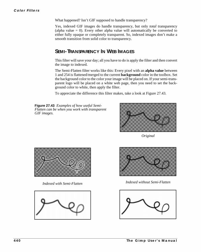
C o l o r F i l t e r s
toke a
ert
ns-ack-
What happened? Isn’t GIF supposed to handle transparency?
Yes, indexed GIF images do handle transparency, but onlytotal transparency(alpha value = 0). Every other alpha value will automatically be convertedeither fully opaque or completely transparent. So, indexed images don’t masmooth transition from solid color to transparency.
SEMI-TRANSPARENCY IN WEB IMAGES
This filter will save your day; all you have to do is apply the filter and then convthe image to indexed.
The Semi-Flatten filter works like this: Every pixel with analpha valuebetween1 and 254 is flattened/merged to the currentbackground color in the toolbox. Setthe background color to the color your image will be placed on. If your semi-traparent logo will be placed on a white web page, then you need to set the bground color to white, then apply the filter.
To appreciate the difference this filter makes, take a look at Figure 27.43.
Original
Indexed with Semi-Flatten Indexed without Semi-Flatten
Figure 27.43 Examples of how useful Semi-Flatten can be when you work with transparentGIF images.
4 4 0 T h e G i m p U s e r ’ s M a n u a l

C h a p t e r 2 7
d in
in
SMOOTH PALETTE
Smooth Palettecreates astriped palettefrom the colors in your image. Thepalette is helpful for when you want to see what kinds of colors you have usean image, but the main purpose of this filter is to createcolormaps for use withright-click|Filters|Render| Flame (see “Flame” on page 592).
VALUE INVERT
Value Invert inverts the image inHSV space. It will not alter Hue andSatu-ration. It just inverts the brightness value without changing the basic colorsyour image.
The effect can be very useful if you are usingCurves to change a certain valuedramatically, and you get stuck with the wrong (inverted) color.
Figure 27.44 Value Invertwas applied to the right sideof the image
T h e G i m p U s e r ’ s M a n u a l 4 4 1


C H A P T E R
28 Combine FiltersThe smash-them-together factory. If you want tocombine several images into one, fade images intoeach other or even create a piece of celluloid film,these are the filters to use.
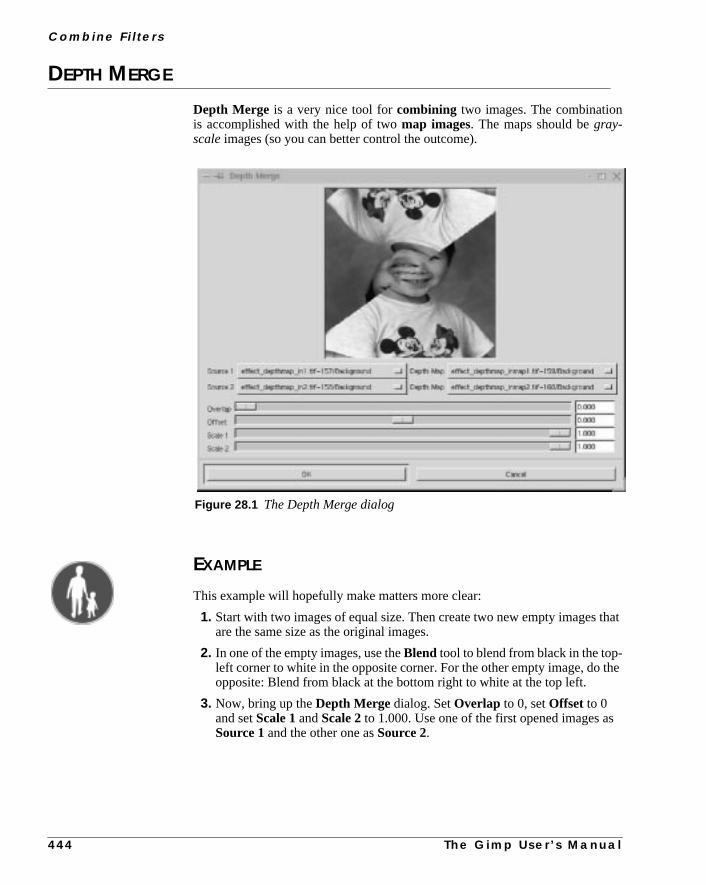
C o m b i n e F i l t e r s
that
the
s
DEPTH MERGE
Depth Merge is a very nice tool forcombining two images. The combinationis accomplished with the help of twomap images. The maps should begray-scale images (so you can better control the outcome).
EXAMPLE
This example will hopefully make matters more clear:
1. Start with two images of equal size. Then create two new empty imagesare the same size as the original images.
2. In one of the empty images, use theBlend tool to blend from black in the top-left corner to white in the opposite corner. For the other empty image, doopposite: Blend from black at the bottom right to white at the top left.
3. Now, bring up theDepth Merge dialog. SetOverlap to 0, setOffset to 0and setScale 1andScale 2 to 1.000. Use one of the first opened images aSource 1 and the other one asSource 2.
Figure 28.1 The Depth Merge dialog
4 4 4 T h e G i m p U s e r ’ s M a n u a l

C h a p t e r 2 8
aresaplineels
a
par-
tive
nd
ththeye’s
will
4. Set the first blended image asDepth Map for Source 1, and the otherblended image as the Depth Map for Source 2. The preview window willdisplay the two imagescombined and a sharp border will appear diagonallyfrom the top right to the bottom-left.
HOW DOES DEPTH MERGE WORK?
What causes this effect? Well, the plug-in looks at both map images, and compevery pixel. The map with the darkest pixel will win, and the source to that mwill show its image pixel. When we created our grayscale images, a cleandiagonally from top right to bottom left separates where the darkest pixchanged from one map to the other.
Now that you understand the basics, you can create all kinds of maps.
ParametersLet’s see what thesliders can do for us. As you saw in our example, there wassharp border between the images. This was becauseOverlap was set to zero. Ifwe slide it up a bit, you will see that the border becomes more fuzzy and transent. Use Overlap if you want to createsoft transitions.
Offset changes the darkness value of your maps. If you slide it to a negavalue, the map to Source 1 will becomedarkerand therefore control more of theresulting image. If you slide it to a positive value, the other map will get darker awill control more of the resulting image.
TheScale 1andScale 2sliders make the Depth Map for Source 1 and the DepMap for Source 2 darker or lighter. They have the same effect as Offset, butare more sensitive. When you scale to a lower value, it will affect the map imagvalue, making it darker and thereby more dominant in the merge; that is, yousee more of the image that the map is serving.
T h e G i m p U s e r ’ s M a n u a l 4 4 5

C o m b i n e F i l t e r s
Figure 28.2 Theseexamples show theresults of using differentsettings for Offset andOverlap
Map 1
Map 2
Source 1
Source 2
No Offset or Overlap Overlap Offset
4 4 6 T h e G i m p U s e r ’ s M a n u a l

C h a p t e r 2 8
you
s
FILM
Film creates a film celluloid of one or more images; a nice special effect.
HOW TO USE THE FILM FILTER
Film’s user interface is quite simple. UnderAvailable images, you have a listall available images. Select an image and clickadd to use it in your film.
On film shows the pictures on your film. To change the order of the pictures,have to add and remove pictures.
Height is the height of the outcoming film.
Color is the film color (black). The plug-in will automatically adjust your imageso that they will fit.
Figure 28.3 The Filmfilter
Figure 28.4 The Film dialog
T h e G i m p U s e r ’ s M a n u a l 4 4 7

C o m b i n e F i l t e r s
m-
ou
heged
r-
e
saiclageews-
hn it.
ith
Numbering lets you specify a start number on the roll. Set numbering to Nubering/Startindex.
Font lets you choose the font that is showing the frame numbers in the film (yhave to have the font installed).
Color is the color of the frame numbers in your film (orange by default). Both tcolor of the film itself (usually black) and the color of the numbers can be chanby clicking on the color swatches.
Check theat top andat bottom checkboxes if you want numbers there; othewise, leave them unchecked.
FUSE
Fusecreates a new image fromtiles of one or several input images. You can usthis filter in two ways.
TEMPLATE
First, you can use thetarget image as atemplate. The result will be an imagethat looks like a mosaic or cubist version of the original image, where the mostones or cubes consist of pieces of the input image (a little like modernist colart where you create a composite image by cutting and pasting pieces of a npaper).
FUSING
You can also create a new shape byfusing one or more images. This filter usesassociative image reconstruction, meaning that it will search out pieces that matcwhere they overlap, thus creating a pattern with more or less “solid objects” iThe new pattern is a random mix of matching tiles from the source images, wa direction tendency toward the center of the image.
Figure 28.5 Fused usedas a template
Original Fused as template
4 4 8 T h e G i m p U s e r ’ s M a n u a l

C h a p t e r 2 8
ble
m.
nless
tion
The Fuse dialog displays a window at the top of the dialog with a list of availaimages(note that indexed images are not accepted). You can select one or all ofthe images in this list by clicking on them. Click on them again to deselect the
Note: The image you opened Fuse from is not used in the fusing process uyou select it in this menu or check the use target as template checkbox.
PARAMETERS
The parameters list starts withTile Size, which controls the size in pixels of thesquare tiles. Small tiles produce smoother images, but will make the operavery slow.
Figure 28.6 These picturesshow the difference betweenfusing the original with itselfand fusing the original withanother image
Fused original only Fused original +other image
Figure 28.7 The Fuse dialog
T h e G i m p U s e r ’ s M a n u a l 4 4 9

C o m b i n e F i l t e r s
theitem-Tile
itsother
sthe
-
setas
Overlap determines by how many pixels the selected tiles should overlap infused image. If Overlap is too low, you’ll get small black gaps in the composimage, and if it’s too high, the process will slow down a great deal. The recomended amount of Overlap is somewhere between a quarter and a third of theSize.
Search Timerefers to how long the filter should search for the tile that best fthe Overlap. Search Time also slows down the process, but results in a smooutput.
When you checkuse target as template, Fuse has to determine whether it imore important to find a tile that matches the template, or a tile that matchesOverlap.
If you set theTemplate weight slider to a high value, you’ll get a good representation of the target image, but the image will look much more“cubist” than afused image without the template (but with the same parameter value). If youthe Template weight lower, you’ll get a smoother image, but it will not bearmuch resemblance to the template image.
4 5 0 T h e G i m p U s e r ’ s M a n u a l


C H A P T E R
29 Cryptographic FiltersSo, you want to be a secret agent? You may want touse these filters to encrypt and hide your information.
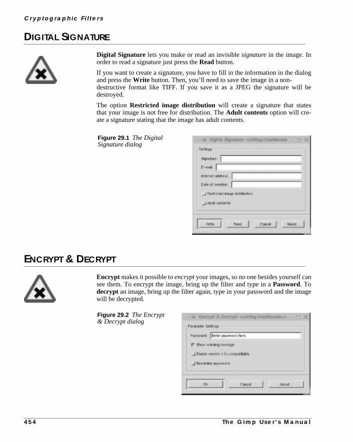
C r y p t o g r a p h i c F i l t e r s
og
be
n
age
DIGITAL SIGNATURE
Digital Signature lets you make or read an invisiblesignaturein the image. Inorder to read a signature just press theRead button.
If you want to create a signature, you have to fill in the information in the dialand press theWrite button. Then, you’ll need to save the image in a non-destructive format like TIFF. If you save it as a JPEG the signature willdestroyed.
The optionRestricted image distribution will create a signature that statesthat your image is not free for distribution. TheAdult contents option will cre-ate a signature stating that the image has adult contents.
ENCRYPT & DECRYPT
Encrypt makes it possible toencryptyour images, so no one besides yourself casee them. To encrypt the image, bring up the filter and type in aPassword. Todecrypt an image, bring up the filter again, type in your password and the imwill be decrypted.
Figure 29.1 The DigitalSignature dialog
Figure 29.2 The Encrypt& Decrypt dialog
4 5 4 T h e G i m p U s e r ’ s M a n u a l

C h a p t e r 2 9
tees)..
bynotsion.
that
the
ion
This. If
k on
the
The author of this filter, Daniel Cotting, warns that he can provide no guaranthat this filter will work (but for us at Frozenriver, this filter has worked just fineRemember not to save the image in a destructive file format, such as JPEG
You can enable backward compatibility with the 1.0 versions of this plug-inclicking on the appropriate checkbox, but we suggest that you stick with 2 andenable this feature unless you have images that are encrypted with the 1.0 ver
You can also enable the plug-in to remember your password, but don’t forgetpasswords are best kept in your own mind where no one can see them.
GIMP MASK
Gimp Mask works by masking the entire image or selected parts of it.Unmask-ing is performed by running the filter once again on the selected area, usingcorrectcode wordfor CP masks or by reversing the direction forMEKO masks.In most cases, you also have to fine-tune theOffset coordinates on theAdjust-ment tab to get the two masks to fit.
Use theRectangleselection tool when specifying the mask area. Other selectshapes may not create the mask area properly. When youreselectthe maskedarea (in order to unmask it), an overlap of up to seven pixels is acceptable.means that it’s OK to make a slightly bigger selection to cover all of the maskyou should fail to get a perfect fit when you reverse the masking process, clicCancel and try again, this time with a smaller selection.
Note that the CP code is not compatible with JPEG files, so if you’re usingJPEG file format, you should choose another mask type.
Figure 29.3 The Gimp Mask dialog
T h e G i m p U s e r ’ s M a n u a l 4 5 5

C r y p t o g r a p h i c F i l t e r s
.
ndive
STEGANO
TheSteganofilter lets youhide or read ahidden fileinside your image. Toreadthe hidden file, pressRead. To hidea file, pressWrite and thenBrowse(to findthe file). There is no restriction concerning the file type that you want to hide
Remember that if you want to hide a big file, you’ll need to use a big image. Ajust like with the other encrypt filters, you can’t save your image in a destructfile format like JPEG. This filter is perfect for secret agents like 007. ;-)
Figure 29.4 TheStegano dialog
4 5 6 T h e G i m p U s e r ’ s M a n u a l


C H A P T E R
30 Distort FiltersDo you feel that your image lacks a certainsomething? Here are the ultimate distort toolsprovided by Gimp.

D i s t o r t F i l t e r s
ilter,ing
al)al
mromer-
ller of
h
eeral
BEND
Bendcanbendthe contents of a layer or the entire image(but it can’t bend a selec-tion). However, because the size of the layers increases when you run this ffull-sized layers will end up being larger than the image area and some clippwill be required.
BEND ORIENTATION PARAMETERS
The Depth parameter controls theamountand direction of the horizontal dis-placement (or vertical if you check theBend Vertical checkbox).
A depth of 100 or (-100) means that the layer width (or height for Bend Verticwill stretch to double its original size, but it will stay centered around its originposition.Negative valuesbend from top to left instead of from top to right, andfrom left to top instead of from left to bottom (Bend Vertical).
De-Center controls the center of gravity of the displacement. The maximuvalue (100) will reverse the directions mentioned above. Instead of bending fthe top and down, the layer content will bend from the bottom up, and Bend Vtical will bend from right to left. With the mid-value (50), the layer content wibend in a perfect U-shape, and the curve will be drawn toward the new centgravity for higher or lower values.
OTHER PARAMETERS
The Fill Bordercolor option will fill the background (vertically or horizon-tally) with the color of the edge pixels of the original layer. You can also fill wittransparency by checking theFill Transparent checkbox instead.
The Keep Original Layer checkbox will keep the original image, and creata new layer for the bent image. This can be handy if you want to create sevbends from the same image.
Figure 30.1 The Bend dialog
4 6 0 T h e G i m p U s e r ’ s M a n u a l

C h a p t e r 3 0
fend-be
ing
Bend the whole imagewill show the entire (bent) image. Normally, some othe bent parts will be clipped when you bend the entire image instead of just bing a small layer. If you check this option, the canvas size will automaticallyenlarged so that you’ll be able to see all parts of the image.
BLINDS
Applying Blinds is like slicing your image or selection in shreds and then pastthe slices to the different sections of window blinds.
Figure 30.2 The original image, and the result after applying Bend
BentOriginal
Figure 30.3 The right part of theimage has been altered with Blinds
T h e G i m p U s e r ’ s M a n u a l 4 6 1

D i s t o r t F i l t e r s
an
ool-
blinds
be
hend
d
tally
PARAMETERS
If you want a transparent background, you’ll need to work in layers or addalpha channel (right-click|Layers| Add Alpha Channel ) to thebackground. Otherwise, the background will be the background color in the tbox, and theTransparent Background checkbox will be grayed out, so youcan’t check it.
You can create eitherVertical or Horizontal blinds; just check the appropriatebutton.
The Displacement parameter refers to the openangle of the blind. A zerodegree angle closes the blinds. A 90 degree Displacement angle opens theas much as possible.
The Num Segmentsparameter controls how many sections the image willcut into by the blinds.
CURTAIN
TheCurtain filter makes it appear as if you are looking at your image through tfabric of a thinly woven curtain. Only, this curtain has a pattern printed on it, athat pattern is your image.
When you apply this filtervertically , the image is copied. This copy is rotate180 degrees, thinly slashed and then combined with the original image.
If you chooseApply horizontal curtain , the same effects will be applied, bufrom a horizontal perspective. You can choose to apply the filter both horizontand vertically at the same time.
Figure 30.4 Curtain
4 6 2 T h e G i m p U s e r ’ s M a n u a l
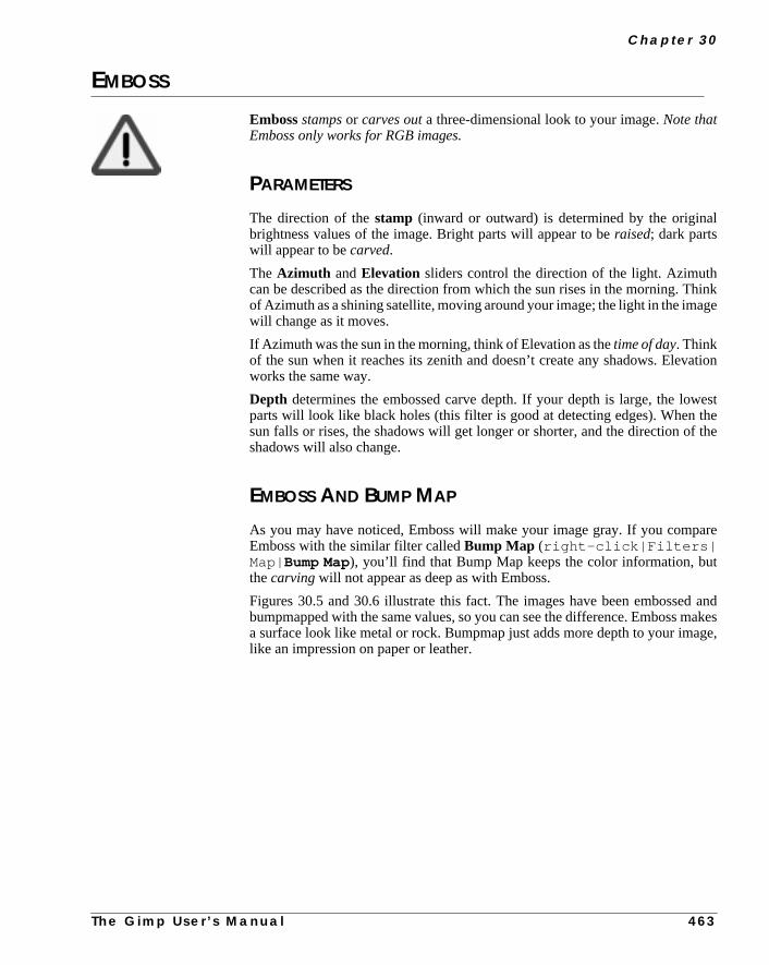
C h a p t e r 3 0
l
hinkge
ation
westthethe
are
t
d andakes
ge,
EMBOSS
Embossstampsor carves outa three-dimensional look to your image.Note thatEmboss only works for RGB images.
PARAMETERS
The direction of thestamp (inward or outward) is determined by the originabrightness values of the image. Bright parts will appear to beraised; dark partswill appear to becarved.
The Azimuth andElevation sliders control the direction of the light. Azimuthcan be described as the direction from which the sun rises in the morning. Tof Azimuth as a shining satellite, moving around your image; the light in the imawill change as it moves.
If Azimuth was the sun in the morning, think of Elevation as thetime of day. Thinkof the sun when it reaches its zenith and doesn’t create any shadows. Elevworks the same way.
Depth determines the embossed carve depth. If your depth is large, the loparts will look like black holes (this filter is good at detecting edges). Whensun falls or rises, the shadows will get longer or shorter, and the direction ofshadows will also change.
EMBOSS AND BUMP MAP
As you may have noticed, Emboss will make your image gray. If you compEmboss with the similar filter calledBump Map (right-click|Filters|Map| Bump Map), you’ll find that Bump Map keeps the color information, buthecarving will not appear as deep as with Emboss.
Figures 30.5 and 30.6 illustrate this fact. The images have been embossebumpmapped with the same values, so you can see the difference. Emboss ma surface look like metal or rock. Bumpmap just adds more depth to your imalike an impression on paper or leather.
T h e G i m p U s e r ’ s M a n u a l 4 6 3

D i s t o r t F i l t e r s
ch-ustage
kthis
ENGRAVE
Engravemakes your image look like anetching.
TheHeight slider determines the depth of the engraving. For more realistic etings, use low Height values (close to 3). In order for Engrave to work you mhave an image with alpha enabled (transparency); a plain RGB or grayscale imwill not work. Try right-click|Layers| Add Alpha Channel toenable transparency.
The Limit line width checkbox will limit the number of allowed line widths,thus reducing the visual impression of having manyshades of grayin the image.You will get more contrast if you don’t check this button, and the etching will loomore realistic. On the other hand, you can get quite interesting results withoption checked.
Figure 30.5 The right side of the imagewas altered with Bumpmap
Figure 30.6 The right side of the imagewas altered with Emboss
4 6 4
T h e G i m p U s e r ’ s M a n u a l
C h a p t e r 3 0
ort
IWARP
IWarp is Gimp’s answer to Kai’s Power Goo. IWarp is quite an amazing distfilter.
Figure 30.7 Engrave wasapplied to the right part of theimage
Figure 30.8 Well,do we need to saymore? The cat iscertainly not a catanymore!
T h e G i m p U s e r ’ s M a n u a l 4 6 5

D i s t o r t F i l t e r s
the
theyou
ons
e
.
ou
ct
You can set the amount of distortion (the Deform Amount) and how largedeformation zone should be (the Deform Radius).
To create a distortion, click on the radio button for the desired effect, and dragmouse in the preview image where you can watch the distortion take place. Ifare not satisfied with a distortion, click theResetbutton and the image will returnto its original state. Similar to Power Goo, you can also animate the distortiyou’ve just made and play them like a film.
THE SETTINGS TAB
• Deform Radius: Sets the size of the distortion area around your mouspointer. The Deform Radius is theradius in pixels from the center of themouse pointer.
• Deform Amount: Sets the amount of deformation on a scale from 0.00to 1.00.
• Move distortion: Allows you tostretch parts of the picture. Forexample, you can stretch a tiny nose into something a witch could beproud of.
• The Grow andShrink distortions should be self-explanatory.
• Swirl: Twists a part of the image, either clockwise or counterclockwise
• Remove: Removes an entire distortion effect, or just part of the effect.Remove is the perfect tool for adjusting a distortion. Remove allows yto avoid pressingReset (and starting again) if you failed to create theeffect you wanted.Note that if you are making an animation, thecorrection will appear in one of your frames.
• Reset: Simply resets the image to its original state.
• Bilinear: If checked, the warping effects will become more smooth.
• Adaptive Supersample: An option that slightly improves thesmoothness of distortion by adding a few intermediate colors. The effeis often quite subtle, unless this option is used for very small areas.
4 6 6 T h e G i m p U s e r ’ s M a n u a l

C h a p t e r 3 0
can
k-ant
u-ou
the
.dis-
rtedongfilter
THE ANIMATE TAB
The parameters on the Animate tab control the distortion animation that youcreate with IWarp.
If you check theAnimate button, you will create a layered image, ready for maing GIF animations. You can set the number of frames and in what order you wto play the frames of the film.
If you don’t checkReverseor Ping Pong, you’ll play the animation innormalmode: The first frame is the original image, and the following frames are gradally distorted until the last frame, which displays the fully distorted image ymade in the preview window.
Reverse will play the animation backwards from the fully distorted image tooriginal image.
The Ping Pong effect creates the following frame sequence: original image..torted image...original image, etc.
Reverse and Ping Pong together create the following sequence: distoimage...original image...distorted image, etc. With Reverse and Ping Ptogether, you must remove the background layer after you have applied theto make it work properly.
Figure 30.9 The main IWarp dialog
T h e G i m p U s e r ’ s M a n u a l 4 6 7

D i s t o r t F i l t e r s
u
t upnds
cy in
ow
theurlts of
Click on theOK button and IWarp will warp the frames for the animation. Yocan use right-click|Filters|Animation| Animation Play-back to view the animation.
Don’t worry about how to save the animation. Because the animation is builon layers, it will be saved if you save the image in a file format that understalayers (such as XCF and GIF).
PAGECURL
Pagecurl allows you to lift and curl a corner of your image.
To be able to use Pagecurl, you must have at least twolayers (including the back-ground layer) or an alpha-enabledbackground in your image (selectright-click|Layers| Add Alpha Channel ). By invoking theAdd Alphacom-mand, or by adding a new layer, you have made it possible to use transparenthe image, and that is needed by the Pagecurl plug-in.
The top layer will curl and thebottom layer will showunder the curl. If yourimage is only a background layer with alpha, the background will curl up to shthe transparency.
The color of the back of the curled page is controlled by the current colors intoolbox. The background color will be the highlight, or the middle part of the cgradient, and the foreground color will be the shadow, or the first and last parthe curl gradient. You can also check theUse current Gradient instead of
Figure 30.10 The IWarp Animation
4 6 8 T h e G i m p U s e r ’ s M a n u a l

C h a p t e r 3 0
byand
g thethe
age-ick
FG/BG-Color checkbox. With this option, the current gradient (determinedthe settings in the Gradient Editor) will be used instead of the foregroundbackground colors.
The Pagecurl dialog also allows you to put a shade under the curl by checkinShade under curlcheckbox and to set the opacity of the curled page usingCurl opacity slider.
If you just want to curl a small part of the image, make a selection and then Pcurl the selection. This allows you to make a small curl, as if the glue didn’t stproperly to that corner of the image.
Figure 30.11 The Pagecurl dialog
Figure 30.12 An example of Pagecurl
T h e G i m p U s e r ’ s M a n u a l 4 6 9

D i s t o r t F i l t e r s
lug-can
ionit
s
POLAR COORDS
Polar Coords can be used to create distortedcircular or rectangular repre-sentations of your image.
EXAMPLES
To create a powerful but rather unsophisticated text curve, you can apply this pin to a text string. You can also make a target circle out of some lines, or youmake rectangles out of straight lines.
The SlidersTheCircle depth in percent slider controls how round the curve will be.
If you apply the filter to your image like the one in Figure 30.14 and set this optto a high value, you will make it circular (Figure 30.15); a lower value makesrectangular (Figure 30.16).
TheOffset angleslider controls where the circle/half-circle will start in degree(see Figure 30.17).
Figure 30.13 ThePolarize dialog
4 7 0 T h e G i m p U s e r ’ s M a n u a l

C h a p t e r 3 0
eartbe
-
o agure
The ButtonsThe Map from top button controls where the lower part of the original imag(Figure 30.18) will turn up. If the Map from top button is checked, the bottom pwill end up in the center (Figure 30.19). If it is unchecked, the bottom part willdistributed around the edges of the image, as in Figure 30.20.
TheMap Backwards option is a mirror function. The effect is the same as flipping the image with the Flip tool in the toolbox.
ThePolar to Rectangular button sets whether the image should be mapped tcircular or rectangular shape. Press this button and the original image (Fi30.18) will map to rectangular Figure 30.21.
Figure 30.14 Originalimage
Figure 30.15 Highvalues for circle depth
Figure 30.16 Low valuesfor circle depth
Figure 30.17 The offsetangle
T h e G i m p U s e r ’ s M
a n u a l 4 7 1
D i s t o r t F i l t e r s
Figure 30.18 Originalimage
Figure 30.19 Map fromtop checked
Figure 30.20 Map fromtop unchecked
Figure 30.21 Polar toRectangular checked
Figure 30.22 The effect ofPolar Coords is very evident inthese images, but you shouldkeep in mind that it’s not just astart and go filter; you oftenhave to choose an appropriateimage or prepare the imagebefore you apply the PolarCoords filter Original
After applying Rectangular coordinates
4 7 2
T h e G i m p U s e r ’ s M a n u a l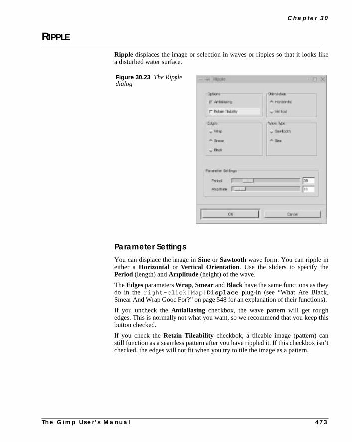
C h a p t e r 3 0
like
y
s).
this
nsn’t
RIPPLE
Ripple displaces the image or selection in waves or ripples so that it looksa disturbed water surface.
Parameter SettingsYou can displace the image inSineor Sawtoothwave form. You can ripple ineither a Horizontal or Vertical Orientation . Use the sliders to specify thePeriod (length) andAmplitude (height) of the wave.
TheEdgesparametersWrap , SmearandBlack have the same functions as thedo in the right-click|Map| Displace plug-in (see “What Are Black,Smear And Wrap Good For?” on page 548 for an explanation of their function
If you uncheck theAntialiasing checkbox, the wave pattern will get roughedges. This is normally not what you want, so we recommend that you keepbutton checked.
If you check theRetain Tileability checkbok, a tileable image (pattern) castill function as a seamless pattern after you have rippled it. If this checkbox ichecked, the edges will not fit when you try to tile the image as a pattern.
Figure 30.23 The Rippledialog
T h e G i m p U s e r ’ s M a n u a l 4 7 3

D i s t o r t F i l t e r s
n’te
ion
SHIFT
Shift creates a random displacement of eachpixel row, horizontally or verti-cally.
The Shift Amount slider sets how much a row should be displaced. You cacontrol whether it will displace left or right/up or down; you can only control thamount of displacement.
TWIST
Twist is a versatile plug-in that provides a variety of geometric image distortfunctions.
Figure 30.24 Thecat’s head is beingrippled away
Figure 30.25 Shift wasapplied to the top of thisimage
4 7 4 T h e G i m p U s e r ’ s M a n u a l

C h a p t e r 3 0
ec-m-
sted,
am-
g for
o
inurtion
elect.
er of
HOW DOES IT WORK?
Twist distorts the image by translating the original pixels according to a 2-D vtor field, which is determined by the selected distortion function. Certain paraeters (up to eight, depending on the function type selected) can be adjuresulting in different effects.
Twist’s output is a geometrically distorted image. The effect of a selected pareter setting can be viewed in apreview window. Each selectable function pro-vides eight predefined effects that can help the inexperienced user get a feelinthe settings. Currently, eight different distortion functions are available.
Note that you cannot distortindexed images. Convert your indexed image tRGB or grayscale before you use Twist on it.
Twist’s dialog is divided into four sections:Preview image, Parameter set-tings, Functions/Effects andCutoff function .
FUNCTIONS/EFFECTS
Under Functions/Effects, you can choose from several distortion functionsthe Functions pull-down menu. After you choose a distortion function, yomust choose parameter settings that, in combination with the chosen distofunction, achieve the effect you want.
There are two ways to define a parameter set. The first and easier way is to sone of eight effects from theEffects pull-down menu under Functions/EffectsThe parameters defining the effect will be displayed in theParameter settings.The effect on the image can be seen in the Preview image at the top-left cornthe dialog.
Figure 30.26 The right side ofthis image was altered with Twist
T h e G i m p U s e r ’ s M a n u a l 4 7 5

D i s t o r t F i l t e r s
nc-f the
entxe-illfine-
on
uct
it isat
PARAMETER SETTINGS
The second way to choose a parameter set is to manually set theParameter set-tings sliders. Note that some of the sliders may not be available for certain futions; those parameters will not affect the image distortion effect. The labels osliders depend on the distortion function.
To get a feel for the parameters of each distortion function, you should experimwith the sliders. If you feel that the preview image is too small, go ahead and ecute Twist by pressing the OK button at the bottom of the dialog. Twist wremember all the parameters you selected when it is started again, so you cantune an effect.
CutoffTheCutoff function provides a mechanism for dampening the image distortifunction, depending on the distancer from the image’s center. So if theUse cut-off checkbox is checked when Twist is activated, the image distortion is a prodof the selected distortion function and of the Cutoff function.
Some of the predefined effects use the Cutoff function, so be sure to notice ifused when you’re trying to figure out which parameters will yield an effect thyou like.
Figure 30.27 Twist’s dialog
4 7 6 T h e G i m p U s e r ’ s M a n u a l

C h a p t e r 3 0
ed
ev-lues
andAinks.
lt is
kes
VALUE PROPAGATE
Value Propagatespreads(or propagates) certain value ranges in a specifidirection.
PROPAGATE MODES
More White And More BlackThe first two parameters,More White andMore Black, have a large impact onscanned photographs(see Figure 30.28). You might describe the effect as aswell-ingof bright (or dark) areas where the contrast is high. When you run the filter seral times, those areas will clog together in large square clusters, but middle vawill remain relatively unaffected.
The result is often quite artistic. The More White effect resembles oil painting,More Black looks like watercolor. This filter is also very good for drawings.black-and-white line drawing made on the computer will look more like a realpen drawing if you use More White on it. More Black will just thicken the line
Other Propagate ModesThe other Propagate modes work best withdrawingsand computer-made imageswith distinct edges. Scanned photos are either hardly affected, or the resustrange and unpredictable.
Original More White More Black
Figure 30.28 Value Propagate can create very interesting effects. The boy definitely looks morechubby when you apply Value Propagate with More White. More Black, on the other hand, mahim lose a few pounds.
T h e G i m p U s e r ’ s M a n u a l 4 7 7
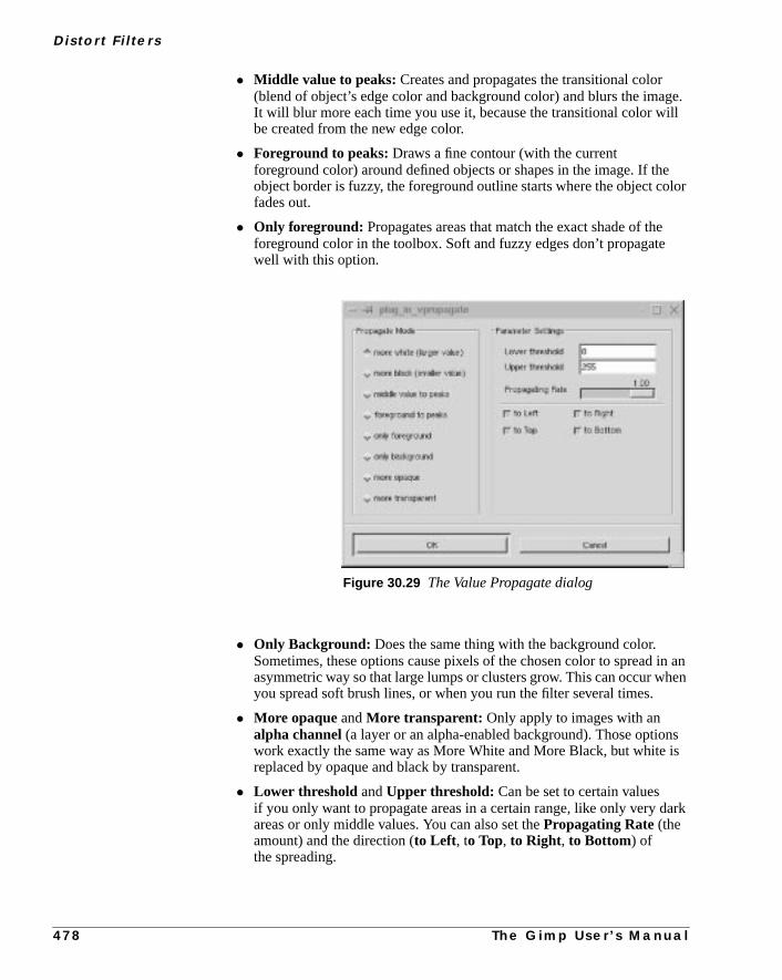
D i s t o r t F i l t e r s
ge.ll
elor
in anen
sis
ark
• Middle value to peaks: Creates and propagates the transitional color(blend of object’s edge color and background color) and blurs the imaIt will blur more each time you use it, because the transitional color wibe created from the new edge color.
• Foreground to peaks: Draws a fine contour (with the currentforeground color) around defined objects or shapes in the image. If thobject border is fuzzy, the foreground outline starts where the object cofades out.
• Only foreground: Propagates areas that match the exact shade of theforeground color in the toolbox. Soft and fuzzy edges don’t propagatewell with this option.
• Only Background: Does the same thing with the background color.Sometimes, these options cause pixels of the chosen color to spread asymmetric way so that large lumps or clusters grow. This can occur whyou spread soft brush lines, or when you run the filter several times.
• More opaque andMore transparent: Only apply to images with analpha channel (a layer or an alpha-enabled background). Those optionwork exactly the same way as More White and More Black, but white replaced by opaque and black by transparent.
• Lower threshold andUpper threshold: Can be set to certain valuesif you only want to propagate areas in a certain range, like only very dareas or only middle values. You can also set thePropagating Rate (theamount) and the direction (to Left, to Top, to Right, to Bottom) ofthe spreading.
Figure 30.29 The Value Propagate dialog
4 7 8 T h e G i m p U s e r ’ s M a n u a l

C h a p t e r 3 0
he
the
n).
• Propagate Alpha andValue Channel: Can be unchecked andthereby prevent that the alpha and/or value channels are affected by tpropagation.
WAVES
Wavessimulates the effect that you get when you throw a stone in a pond (ifReflective checkbox is unchecked).
PARAMETER SETTINGS
• TheAmplitude slider controls theheight of the waves.
• ThePhase slider sets the position in the wave.
• The Wavelength slider controls the length of the waves.
• TheSmear andBlacken Modeswork the same as they do inright-click|Filters|Map| Displace (see “What Are Black, Smear AndWrap Good For?” on page 548 for an explanation of Smear and Blacke
• If you check theReflective checkbox, you will not get the simple“thrown stone” effect. Instead, your wave will create an interferencepattern.
Figure 30.30 The Waves dialog
T h e G i m p U s e r ’ s M a n u a l 4 7 9
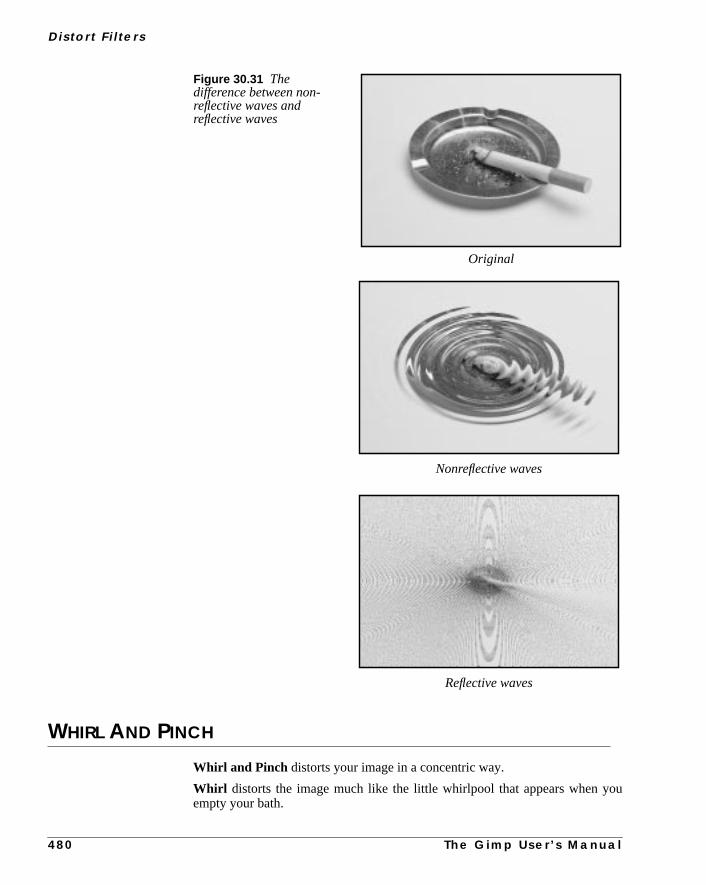
D i s t o r t F i l t e r s
ou
WHIRL AND PINCH
Whirl and Pinch distorts your image in a concentric way.
Whirl distorts the image much like the little whirlpool that appears when yempty your bath.
Figure 30.31 Thedifference between non-reflective waves andreflective waves
Original
Reflective waves
Nonreflective waves
4 8 0 T h e G i m p U s e r ’ s M a n u a l

C h a p t e r 3 0
ress-
the
usill
ius
Pinch can be compared to applying your image to a soft rubber surface and ping it in different ways. If thePinch amount slider is set to anegativevalue, itwill look as if someone tried to push a round object up toward you from behindrubber skin. If Pinch amount is set to apositivevalue, it looks like someone isdragging or sucking on the surface from behind, and away from you.
ParametersThe Whirl angle slider controls how many degrees you want torotate yourimage.
TheRadiusslider sets how much of your image will be affected. If you set Radito 2, the entire image will be affected. If you set Radius to 1, half the image wbe affected. If Radius is set to 0, nothing will be affected (think of it as the radin a circle with 0 in the center and 1 halfway out).
Tip: To create a really realistic whirlpool, combine Whirl and Pinch.
Figure 30.32 The effect of Whirl can be quite surreal
WhirledOriginal
T h e G i m p U s e r ’ s M a n u a l 4 8 1

D i s t o r t F i l t e r s
in
esthe
nalFirst,ind
WIND
TheWind filter can be used to createmotion blur , but it can also be used as ageneral distort filter. What’s characteristic about this filter is that it will render thblack or white lines.
Wind will detect the edges in the image, and stretch out thin white or black linfrom that edge. This is why you can create the illusion of motion, becauseedges are what will be blurred in a photograph of a moving object.
Let’s take a look at the train in Figure 30.34. There is no motion in the origiimage, but in the second image we added some wind to get the train started.we created a new layer, we copied the train into this layer and invoked the Wfilter. The final step was to blur the windows with the convolver tool.
Figure 30.33 The Whirland Pinch dialog
Figure 30.34 Wind was used to create a feeling of motion
No wind, no motion Wind results in motion
4 8 2 T h e G i m p U s e r ’ s M a n u a l

C h a p t e r 3 0
e.
can
ss
Parameter SettingsThe interface is quite simple. You can set theStrength of the wind and aThreshold value. Threshold will restrict the effect to fewer areas of the imag
Strength controls the amount of wind, so a high value will render a storm. Youalso increase the effect by setting theStyle to Blast,which will produce thickerlines thanWind.
You can only set the wind in two directions, eitherLeftorRight. However, you cancontrol which edge the wind will come from using the commandsLeading,Trailing or Both. Because Trailing will produce a black wind, it creates a leconvincing motion blur than Leading, which will produce white wind.
Figure 30.35 Windwas applied to the sameimage using Leading,Trailing and Both
Leading Trailing Both
T h e G i m p U s e r ’ s M a n u a l 4 8 3


C H A P T E R
31 Edge-Detect FiltersLiving on the edge? Gimp provides you with a fewedge-detect filters to help you find your edge.

E d g e - D e t e c t F i l t e r s
so
t,age.es,on-rks.
a
awn
-rse
ll
INTRODUCTION
Edge-Detectfilters search out the borders between areas of different color,they can trace the contours of objects in the image.
For theEdge, Laplace andSobelfilters, the background is black or transparenand the contours are either white or have the same color as in the original imThe results are actually a lot like sgrafitto or other artistic scratching techniquwhere you cover an image with thick oil paint or crayon and then scratch the ctours with a knife or needle so that the original colors appear in the scratch ma
The LoG filter, however, is strictly black and white with a black contour onwhite background.
Edge-Detect filters are often used to makeselectioneasier, but they can also beused for artistic purposes or to achieve effects like simulating a hand-drsketch.
EDGE
Edge will produce a dark image with (mostly) white contours.
You can set theAmount of edge-detect. A high value results in a black, highcontrast image with thin, sharp edges. A low value will produce thick, coaedges with relatively low contrast and lots of color in the dark areas.
The Wrap , Smear andBlack options aren’t operational, so you might as weleave those as they are.
Figure 31.1 The leftpart of the image wasaltered with Edge
4 8 6 T h e G i m p U s e r ’ s M a n u a l

C h a p t e r 3 1
ge
age
anct,
esult,
ro-p,
hitecre-the
r,efine
LAPLACE
Laplace creates a black image with extremely thin (1 pixel wide) colored edlines.
Note: When applied on a layer, Laplace and Sobel result in a transparent imwith thin black edge lines.
Laplace is very useful when you want to put emphasis on the contours ofimage, or make a photograph look like an ink drawing. To achieve this effeduplicate the image and use Laplace or Sobel on the top layer. For the best rapply some blur to the image before running this filter (such asGaussian Blurwith a radius of 0.5 to 5.0).
LOGLoG is a very usefuledge-detectandtracing filter. You shouldn’t compare it totracing programs like Corel Trace or Adobe Streamline for vector drawing pgrams, but if you want to use a similar feature in a bitmap application like GimLoG is an excellent tool.
How To Use LoGThe LoG filter transforms scanned or computer-made images into black-and-wline art drawings, where each line is a closed curve. This makes it possible toate simple yet effective drawings by filling the closed curves with color, usingBucket Fill tool.
You can also use it as atemplateor aid for hand-painted images. Howeveretouching to erase unwanted contours and close certain curves, in order to dthe desired fill area, will be necessary in most cases.
Figure 31.2 The leftside of the image wasaltered with Laplace
T h e G i m p U s e r ’ s M a n u a l 4 8 7

E d g e - D e t e c t F i l t e r s
retedyou
PARAMETERS
You’ll need to set several parameters before applying this filter successfully.
Edge-Detect LinesAllowable PA (percentage of allowable aliasing energy),or the toleratedamount of aliasing, is used to specify how edges are treated.
A high PA gives you a higher level of edge-detecting, which will result in a moprecise line art output of your image. A high PA is recommended on complicaimages where detail is important. Use a low PA on simpler images, or whenwant a clean output.
Figure 31.3 Example showing how you can use LoG to create a cartoon-like image
Original LoG’ed LoG’ed and colorized
Figure 31.4 The LoGfilter dialog
4 8 8 T h e G i m p U s e r ’ s M a n u a l

C h a p t e r 3 1
l inthe
m
e
te
d.alue
-the
C1 tordet the
ich
o
n-
LoG Rendering TypesThere are three types of LoG rendering:Standard LoG, or LoG with RobertsandLoG with Sobel.
Standard LoG is perhaps a bit crude, but graphically clean and very powerfuits simplicity. Standard LoG creates a thick, closed border around objects;higher thePA, the thinner the contour border.
Roberts andSobel trace fine contours without borders and with more realisin the penwork. They make use ofgradients to filter out spurious contours in theimage. Their results arecleanerto look at, but important parts of the image aroften lost.
Adjusting The Level Of DetailTo rectify this loss of image information, you should specify an appropriaThreshold range in the PC1 andPC2 fields. The PC1 threshold field sets thelow threshold limit. Values below the specified value in this field will be ignoreThe PC2 threshold field sets the high limit. Values exceeding the specified vin this field will be ignored.
Values within the specifiedthreshold rangeare traced and displayed in the rendered image. If the image is generally low in contrast, you should increasethreshold range. For a bright image where contours are pale or unclear, set P0 and PC2 to a relatively low value, like 50 or 60. Then, the filter will disregabrighter values and concentrate on tracing darker areas. If the image is dark, sthreshold values in the opposite direction.
If you want moredetail in the traced image, you mustlower theStandard devi-ation value. However, a Standard deviation lower than the default value (whis 2.0) requires a higher PA (3.0 or 10.0) to work properly.Raisingthe Standarddeviation results in larger, softer curves with less detail.
SOBEL
Sobelhas the same effect asLaplace, but the edges are a bit broader and alsa bit more blurred.
If you only apply it in one direction (you can apply it both vertically and horizotally) and checkKeep sign of result, you will get something that looks a lotlike anEmboss effect.
If you only apply it horizontally, you will get more contrast and color in yourimage. If you only apply itvertically, it will get a bit darker and there will be lesscontrast in the image.
T h e G i m p U s e r ’ s M a n u a l 4 8 9

E d g e - D e t e c t F i l t e r s
Figure 31.5 The right side ofthe image was altered with Sobel
4 9 0 T h e G i m p U s e r ’ s M a n u a l


C H A P T E R
32 Enhance FiltersDo you want to sell your old car? Here are the toolsyou’ll need to enhance the advertisement image.

E n h a n c e F i l t e r s
isuit-
s lit-
in
d to
ndyouage,
ADAPTIVE CONTRAST
Adaptive Contrast is a very powerful contrast-enhancing filter. The effectvery strong, sometimes with an almost three-dimensional quality, so it’s not sable for all images.
Contrary to the other enhancing filters in this menu, Adaptive Contrast createtle change in theHue andSaturation values, so if you use it in an image withfaded colors, this filter will not retrieve lost color. It is, however, very effectivefinding and accentuating hidden or fadedBrightness values in an image.
DEINTERLACE
Deinterlace will help you adjust images captured byvideo cards. Sometimes,the even fields or odd fields don’t get captured correctly. This filter can be usecorrect that.
DESPECKLE
Despeckleis the filter to use if your image is noisy, if you scanned an image athere was some dust or fibers in the scanner, if you got a moiré pattern whenscanned a printed image from a magazine, or if your image has physical damlike scratches.
• If your image is justnoisy, or suffers frommoiré effects, use Despeckleover thewhole image.
Figure 32.1 The twoleaves to the left wereenhanced with AdaptiveContrast
4 9 4 T h e G i m p U s e r ’ s M a n u a l
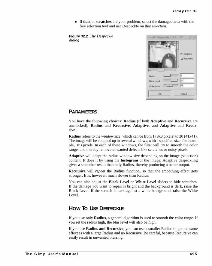
C h a p t e r 3 2
e
.m-
lor
on)
.
ts
thehite
. If
ee can
• If dust or scratches are your problem, select the damaged area with thfree selection tool and use Despeckle on thatselection.
PARAMETERS
You have the following choices:Radius (if both Adaptive andRecursiveareunchecked);Radius and Recursive; Adaptive; and Adaptive and Recur-sive.
Radius refers to thewindow size, which can be from 1 (3x3 pixels) to 20 (41x41)The image will be chopped up in several windows, with a specified size: for exaple, 3x3 pixels. In each of these windows, the filter will try to smooth the corange, and thereby remove unwanted defects like scratches or noisy pixels.
Adaptive will adapt the radius window size depending on the image (selecticontent. It does it by using thehistogram of the image. Adaptive despecklinggives a smoother result than only Radius, thereby producing a better output
Recursive will repeat the Radius function, so that the smoothing effect gestronger. It is, however, much slower than Radius.
You can also adjust theBlack Level or White Level sliders to hide scratches.If the damage you want to repair is bright and the background is dark, raiseBlack Level. If the scratch is dark against a white background, raise the WLevel.
HOW TO USE DESPECKLE
If you use onlyRadius, a general algorithm is used to smooth the color rangeyou set the radius high, the blur level will also be high.
If you useRadius and Recursive, you can use a smaller Radius to get the sameffect as with a large Radius and no Recursive. Be careful, because Recursiveasily result in unwanted blurring.
Figure 32.2 The Despeckledialog
T h e G i m p U s e r ’ s M a n u a l 4 9 5

E n h a n c e F i l t e r s
l
ow-
ursive
n ofage,a
gesge.
If you useAdaptive, the filter will try to calculate the best window size, and wiluse a general algorithm to smooth the color range in each window.
If you useAdaptive and Recursive, an adaptive recursive algorithm will beused. This is very effective and you can use quite small radius values. It will, hever, be even slower than Recursive.
General AdviceTo remove a scratch or other defect, select the damaged area and use Recand Radius.
If you want to remove some noise, use Adaptive or perhaps a combinatioAdaptive and Recursive. If you use Recursive and/or Radius on the whole imit will often get too blurred (this is not a problem when you’re only using it ontiny selection).
DESTRIPE
Destripe corrects images captured from video films, or poorly scanned imawith stripes on them. This filter will add a striped interference pattern to the ima
The scratch has beenselected
After applying Despeckle,the scratch is gone
Figure 32.3 When you want toremove dust and scratches, justselect the scratched area andapply Despeckle, as in theexample provided here
4 9 6 T h e G i m p U s e r ’ s M a n u a l

C h a p t e r 3 2
pat-ng
).
ider
othings
)s
You change the phase by dragging theWidth slider, and if you can find the rightsetting, the two wave patterns will extinguish each other. Because the stripetern will be different for each image, you’ll have to experiment to find the settithat will get rid of the stripes in your original. TheHistogram checkbox will giveyou a better view of the current phase displacement.
NL FILTER
NL Filter is an efficient image enhancing filter (the “NL” stands for non-linear
NL Filter uses a 7-hexagon pixel block that you can adjust with the radius sl(instead of using a fixed 3x3 pixel block for its filter algorithms).
PARAMETERS
NL Filter provides three different filters:Alpha Trimmed Mean , OptimalEstimation andEdge Enhancement.
TheRadius slider controls the strength of the filter.Alpha determines whetherthe filter will just smooth out, or reduce, noise. Recommended values for bRadius and Alpha are between 0.0 and 0.5. If you use values over 0.5, funny thwill happen (but they can be quite artistic).
• UseAlpha Trimmed Mean and set the Alpha to 0.5 when removingsingle noise spots in the image.
• Optimal Estimation is very good for reducing dithering noise. LowAlpha values make the smoothing subtle and high values (around 1.0smooth all parts of the image. Radius should be from 0.8 to 1.0 for thifilter to work correctly.
Figure 32.4 The NL Filter dialog
T h e G i m p U s e r ’ s M a n u a l 4 9 7

E n h a n c e F i l t e r s
ls
s,
ow-noiseu try
me,com-rp-
• Edge Enhancementis the opposite of Optimal Estimation. EdgeEnhancement sharpens edges instead of blurring them. Radius controthe effectiveness of the filter. Useful Radius values range between 0.5and 0.9.
SHARPEN
Sharpen will sharpen unfocused images.
The interface is simple: TheSharpnessslider controls the amount of sharpnesand you judge for yourself using the preview.
Sharpen is one of the more useful tools in Gimp for enhancing photographs. Hever, when you use Sharpen, you risk accentuating not only edges, but alsoor blemishes. If your image is very damaged or noisy, we recommend that yothe NL Filter’s Edge Enhancement option, or theUnsharp Mask filterinstead.
UNSHARP MASK
TheUnsharp Mask filter will enhance your image by making itsharper with-out accentuating the small imperfections in the image. It’s hard to tell by the nabut Unsharp Mask is based on a darkroom technique that was used beforeputer graphics arrived on the scene. Anyway, it’s a very efficient filter for shaening enhancements.
Figure 32.6 The right part of theimage was enhanced with Sharpen
Figure 32.5 The Sharpendialog
4 9 8
T h e G i m p U s e r ’ s M a n u a l
C h a p t e r 3 2
eyee willtherentire
ore
print-
arp-ok
e ishe
ening
ill
this
ses.
5 is and
Why Should I Use Unsharp Mask Instead Of Sharpen?Usually, it’s much better to useUnsharp Mask thanSharpen. The reason forthis is that Unsharp Mask will sharpen the edges in the image, and the humanis very sensitive to unsharp edges. Actually, sharpening the edges in an imagmake the whole image look sharp, because you will not easily detect the oparts that are less sharp. Also, because Unsharp Mask won’t sharpen theimage as much as the Sharpen filter does, the resulting image will look much mnatural than the somewhat artificial look that Sharpen will produce.
Unsharp Mask can also be used to prepare images for Web and professionaling, because it allows you to control the thickness of the edges in an image.
SHARPENING WITHOUT DISTORTING THE COLORS
When you enhance images, you often don’t want the colors to be affected. Shening the colors in an image will usually just distort them and make them lounnatural, and that is no enhancement.
Tip: A useful piece of advice when you wish to sharpen up an unfocused imagto decomposethe image to HSV, and only apply the enhancement filter to tValue part of the image. Afterward, youcomposethe image to RGB and you’llhave a sharpened image where the colors have not been affected by the Sharpprocess.
PARAMETER SETTINGS
Instead of discussing exactly how this filter works in a mathematical way, we wtry to tell you how to use it.
At the time of this writing (September 1999) there are only two parameters infilter. Blur Radius and Combine amount. We will refer to these parametersasRadius andAmount.
• Radius refers to the thickness of the edges in the image. Higher valuewill produce thicker edges and more contrast in the image. Lower valuwill produce fine/crisp edges. You can set the radius to 0.1 and higher
• Amount controls how much the image will be sharpened. This value isnormally specified in percent, but we guess that you understand that 0.the same as 50%. You can set the amount of sharpening to 1% (0.01)higher.
T h e G i m p U s e r ’ s M a n u a l 4 9 9

E n h a n c e F i l t e r s
wandlue.
es.
riate0%)es,ve a
arpssy
liasingthe
ur
2.0ters
So,will
entects
RECOMMENDED VALUES
AmountIf we only had Amount to play with, there would be no problem figuring out hoto use Unsharp Mask. Generally, we recommend starting out with low values,repeating the filter several times instead of applying it once using a high vaBecause Gimp has an excellentundo/redo function, you can easily find out whatvalues you should use to get the best result by redoing/undoing your chang
As a general guideline, values between 0.25 (25%) and 0.5 (50%) are appropfor creating a gentle sharpening effect. Values between 0.5 (50%) and 2.50 (25will produce a stronger sharpening. If you want to create artificial-looking imaghigh values over 4.5 (450%) will do. The given values assume that you haRadius of 1.0.
RadiusRadius determines how thick your edges will be after having applied UnshMask. Low values such as 1.0 will produce very fine edges. Low values on locompressed images (JPEG) can sometimes produce unwanted grain and aedges. If you encounter that problem when you use Unsharp Mask, try raisingRadius value to exceed 1.5.
A Radius from 1.0 to 2.0 will create thicker lines that may look unnatural on yocomputer monitor. They are, however, very useful when you want toprint yourimage. It’s not uncommon to use a low Amount with a Radius between 1.5 andon all images that will be printed in a book, because imagesetters and prindon’t show fine lines as well as a computer monitor.
A rule of thumb is to add 0.2 to the Radius value for each 30 ppi in your image.for example, a 300 ppi image will require a Radius of 2.0 and a 210 ppi imagerequire a Radius of 1.4. The algorithm is as follows:
Radius= (image ppi / 30) x 0.2
The values above are not fixed, and it’s up to your common sense to experimwith different values. Naturally, you can use high values to create special effin your image.
5 0 0 T h e G i m p U s e r ’ s M a n u a l

C h a p t e r 3 2
Original
R=0.5 A=0.5
R=3 A=0.5 R=10 A=0.5 R=20 A=0.5
R=1 A=1.5 R=1 A=2.5 R=1 A=10
R=1 A=0.5 R=2 A=0.5
Figure 32.7 These examples show the result of usingdifferent settings for the Unsharp Mask parameters. R isRadius and A is Amount.
T h e G i m p U s e r ’ s M a n u a l 5 0 1
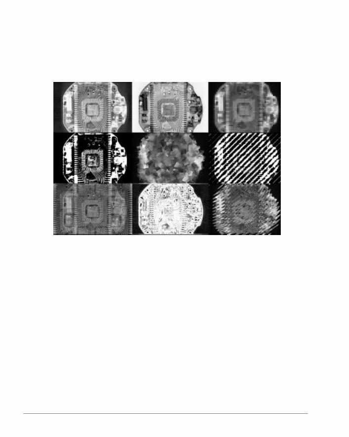
C H A P T E R
33 Generic FiltersThis is the math corner of Gimp. You will find differentkinds of filters that apply mathematical formulas toyour image, as well as Gimp’s equivalent to FilterFactory.

G e n e r i c F i l t e r s
nul-
alueon’t
this
israge
CONVOLUTION MATRIX
Convolution Matrix allows you to create simple custom filters. ConvolutioMatrix adds together the color values in the 5x5 pixel box around each pixel, mtiplying each pixel in the box by the corresponding value from the matrix.
EXAMPLES
It works like this:
Divisor: 1 Offset: 0
The middle value represents the pixel to be modified. Here, the destination vis 1 (the source value and the surrounding pixels are multiplied by 0 so they dcount). The matrix can be used for offsetting. For example:
Divisor: 1 Offset: 1
The destination value for a pixel is the source value of the pixel above it, sooffsets the image one pixel downward. A simple blur works like this:
Divisor: 9 Offset: 0
Now, for each pixel, the value of that pixel and the eight surrounding pixelstaken, added together and divided by nine. Thus, the resulting pixel is the ave
0 0 0 0 0
0 0 0 0 0
0 0 1 0 0
0 0 0 0 0
0 0 0 0 0
0 0 0 0 0
0 0 1 0 0
0 0 0 0 0
0 0 0 0 0
0 0 0 0 0
0 0 0 0 0
0 1 1 1 0
0 1 1 1 0
0 1 1 1 0
0 0 0 0 0
5 0 4 T h e G i m p U s e r ’ s M a n u a l

C h a p t e r 3 3
ed)
luesces
he
t the
e col-ray
set
on.ha
d by
of the 3x3 pixel region around it. Similarly, a very strong (and unsophisticatsharpen filter works like this:
Divisor: 1 Offset: 0
This takes the center pixel, multiplies its value by five, then subtracts the vaof the four immediately adjacent pixels from that. This kind of operation enhanthe differences between colors.
The Divisor argument is just a number by which the result is divided, and tOffset is added to that. The Offset is useful in some cases, such as this:
Divisor: 1 Offset: 128
In this case, the values on the lower right are subtracted from the values aupper left. This produces a basicembossing effect.
Since these values could easily be negative, and a picture can’t have negativors, we add 128 everywhere, making this in all likelihood something like a gbump map.
TheAutomatic checkbox sets theDivisor so that it is the sum of the matrix val-ues. If the sum is positive, the Offset is 0. If the sum is negative, the Offset isto 255 (for inverting). If the Divisor is 0, the Offset is 128 (for embossing).
The Channels checkboxes control which channels the plug-in operatesAlpha adds an additional factor to the calculations: the alpha channel. If Alpis checked, the values of all pixels are weighted both by the matrix values an
0 0 0 0 0
0 0 -1 0 0
0 -1 5 -1 0
0 0 -1 0 0
0 0 0 0 0
0 0 0 0 0
0 1 1 0 0
0 1 0 -1 0
0 0 -1 -1 0
0 0 0 0 0
Figure 33.1 Embossing with thehelp of Convolution
T h e G i m p U s e r ’ s M a n u a l 5 0 5

G e n e r i c F i l t e r s
owng,andf theing
that
er-y.iptionork-
in
areed
be
esxelsnter
nd
in-1
willthe
os-as
after
its alpha value. Try this out by making an image with nearly transparent (lalpha) green and fully opaque red next to it. If you aren’t using alpha weightiand you blur the image, a brownish line will appear between the transparentred regions, because the transparency (the “weakness,” one might say) ogreen wasn’t taken into consideration. With alpha weighting on, the blurrwon’t create any unexpected artifacts.
UNIVERSAL FILTER
There are two different types of signal (image) processing:linear andnonlin-ear. A median algorithm is an example of a nonlinear filter. TheUniversal Fil-ter is a linear filter, which means that you can describe a transfer functiondescribes the output in relation to the input.
In principle, a linear operation is reversible, but in practice a few nonlinear opations (like clipping and quantization) are involved, which limit the reversibilitAs for any linear system, a frequency response can be calculated. This descris going to skip over the mathematics and theory and just describe the basic wing algorithm.
At the moment, the Universal Filter uses a 3x3Matrix and two other parameters(Divider andBias). The extra parameters can be calculated from the Matrixmost cases, but you can set them if you want to.
For every pixel of the new image, the original pixel and the surrounding pixelstaken, multiplied with the values in the Matrix, added to the Bias value and dividby the Divider. If you change the Matrix values, different kinds of filters cangenerated.
If you put the value 1 in every Matrix field (and leave the Divider and Bias valuas calculated), you’ll get a lowpass or blur effect, because you add all nine pito calculate the new one. If you want a smaller effect, you can increase the cevalue so the surrounding pixels will have less effect.
To get a highpass filter or sharpening effect, use a Matrix with -1 in all cells aa 9 in the center.
You can choose to run the filter in just one direction, by only using coefficientsthe middle row or the middle column of the matrix. To invert the picture, put ain the center field.
The values for Bias and the Divider are calculated so that the resulting imagebe in the normal range of 0 to 255 for color or gray values. So the Divider isabsolute value of the sum of the Matrix. If the sum is 0, then theDivider is set toone. The Bias value is derived from the sign of the Matrix sum. If the sign is pitive, the Bias is 0; if it is negative, the Bias will be 255. If the sum is 0, the Bivalue will be 128.
All calculated values are rounded to integers and clipped to the range 0 to 255the computation.
5 0 6 T h e G i m p U s e r ’ s M a n u a l

C h a p t e r 3 3
y fil-
anasbeop.
thean-fil-
e
h
.g.,
eron
ere
ave
st
e
u
ac-
. Aain.
USER FILTER (ADOBE FILTER FACTORY EMULATOR)User Filter is a clone of Adobe Photoshop’sFilter Factory . This is a realgoldmine, because you can use all of the hundreds of available Filter Factorters made forAdobe Photoshop.
An enormous amount of free filters are now available for Gimp. User Filter chandle all the different Filter Factor filter formats: .afs, .txt and .8bf plug-ins,well as .ffl (Filter Factory libraries). Note that you can’t use ordinary .8bf AdoPhotoshop plug-ins with the User Filter; they only work with Adobe Photosh
To understand Filter Factory, you’ll need to read the pertinent sections ofAdobe Photoshop manual. There are too many Filter Factory filters for this mual to describe, but we plan to write some documentation about Filter Factoryters in the future.
To find Filter Factory filters and information about Filter Factory, start with thFilter Factory web page athttp://privat.schlund.de/f/filter-factory/ or search the web for “Filter Factory” with your favorite searcengine.
Notice that you must add the line(userfilter-path “${gimp_dir}/userfilter”) to your personal gimprc file (e.g.,vi ~/.gimp/gimprc ).You must also make a userfilter directory in your personal gimp directory (emkdir ~/.gimp/userfilter ). You can now install your userfilters in the~/.gimp/userfilter directory. Of course you must also have the userfiltplug-in installed on your system. Please read “Compiling Plug-ins” startingpage 769 for how to compile plug-ins and “Web” on page 878 to find out whto download the latest version of User filter.
OPERATING THE USER FILTER
The user interface is quite simple. First, you’ll need to open theFilter Managerfolder, where you can browse through the available filters. When you hdecided which one to use, simply select it and pressLoad.
The preview will show how the result of the filter will appear. If you want to adjuany of the values, open theValue folder. The first time you open theUser Fil-ter, you won’t find any values here, but after your first load/use you will find thvalues you used the last time, or the default values of the last filter.
If you have enabledUpdate, you will be able to see the preview change as yoalter the values. If this isn’t enough, you can open theEdit folder, where you willfind the mathematical expression of the filter. If you understand how Filter Ftory works, you can simply edit the function.
Tip: Sometimes, the User Filter can be quite slow when you scroll the previewsolution to this problem is to disable Update, scroll and then try the preview ag
T h e G i m p U s e r ’ s M a n u a l 5 0 7


C H A P T E R
34 Glass Effect FiltersWould you like to create a fish-eye lens or makeyour image look like it’s behind a wall of glass? Thenyou’ll find some interesting filters here.

G l a s s E f f e c t F i l t e r s
ur
s
ngee
APPLY LENS
Apply Lens places a virtuallens (bulb) on top of your image. If you keep theoriginal surroundings, it will look as if you had placed a crystal ball over yoimage. TheLens reflection indexcontrols howfish-eyedor spherical the lenswill be.
If you set the surroundings toBackground color, you will get the backgroundcolor from the toolbox. WithTransparent surroundings you could create imagesuch as nice surrealist buttons for web pages.
CONICAL ANAMORPHOSE AND CENTRAL REFLECTION
The Conical Anamorphose and Central Reflection plug-ins can best bedescribed by making a parallel to funny mirrors in an amusement park.
If we assume that the image you’re working on is a picture of you, it’s like havia conical/tube mirror, which you are looking into from the bottom. What you sis a highly distorted image.
Figure 34.1 The result ofApply Lens
Before
After
5 1 0 T h e G i m p U s e r ’ s M a n u a l

C h a p t e r 3 4
is-
a
cause
be.se
and.
—
PARAMETER SETTINGS
Naturally, since you are looking into the mirror-tube, you can’t see yourself undtorted, but if you checkKeep original surroundings, you will be able to seeyourself in the center looking into the mirror. If you’d rather fill this area withsolid color, check theSet surroundings to background color button. Takea look at Figure 34.2 to get an idea of how the filters work.
OTHER SETTINGS
The most important parameter settings areRadius andBase angle, which con-trol the shape of the cone/tube (there is no base angle in Central Reflection beit is a tube).
Radiuscontrols the size of the base or circular bottom of the reflecting cone/tuBase angle of conerefers to the steepness of the reflecting cone. The BaAngle must be set to a value between 0 and 90 degrees.
The image is flipped vertically by default to make the image easier to understIf you uncheckFlip image vertically, you will see what you would see if youwere really looking into such a mirror, but this is probably not what you wantit looksvery weird.
We recommend usingAntialias to prevent the image from gettingjaggy. Checkthis button, and you will get a much smoother image.
Figure 34.2 The result of Conical Anamorphose and Central Reflection
Original Conical Anamorphose Central Reflection
T h e G i m p U s e r ’ s M a n u a l 5 1 1

G l a s s E f f e c t F i l t e r s
n
utthe-
e,es
-plitsuser
ELLIPSE
Ellipse is similar to Apply Lens. The effect simulates refracting through aelliptical lens.
You can set the quality of the rendering both horizontally (X-Quality ) and ver-tically (Y-Quality ). Setting high render quality will produce smooth edges, bit will also be slower. If the image is rectangular and the width is greater thanheight, it will render well and relatively fast with a high Y-quality and a low Xquality.
If you check theMake Circle checkbox, the output image will always be squarand the distorted object will be circular. Also, the specified X and Y quality valuwill be averaged and both values will be set to the calculated mean.
GLASS TILE
Glass Tile can make it look like your image is behind aglass wall.
You can set theHeight andWidth of the tiles to a value between 10 and 50 pixels. A perhaps more accurate explanation of what the filter does is that it syour image in X*X pixel tiles, where each tile repeats a small part of the previotile. This behavior will make it look like the object is behind a glass wall or showcurtain.
Figure 34.3 The result of applying the Ellipse filter
Before After
5 1 2 T h e G i m p U s e r ’ s M a n u a l

C h a p t e r 3 4
the
RAX STRUCTURIZER
TheRaX filter will create afunny mirroreffect. It can also be compared to lookingat a water reflection where the waves have no structure. You can controlbehavior of this hallucinating effect filter by dragging the sliders.
Figure 34.4 The rightside of the image wasaltered with Glass Tile
Figure 34.5 The right side ofthe image was altered with RaX
T h e G i m p U s e r ’ s M a n u a l 5 1 3
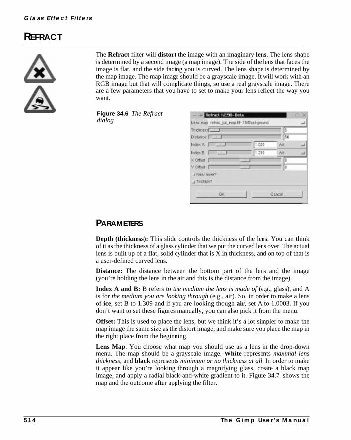
G l a s s E f f e c t F i l t e r s
es thed byan
hereyou
kctualis
age
s
.
theap in
wn
apthe
REFRACT
TheRefract filter will distort the image with an imaginarylens. The lens shapeis determined by a second image (a map image). The side of the lens that facimage is flat, and the side facing you is curved. The lens shape is determinethe map image. The map image should be a grayscale image. It will work withRGB image but that will complicate things, so use a real grayscale image. Tare a few parameters that you have to set to make your lens reflect the waywant.
PARAMETERS
Depth (thickness):This slide controls the thickness of the lens. You can thinof it as the thickness of a glass cylinder that we put the curved lens over. The alens is built up of a flat, solid cylinder that is X in thickness, and on top of thata user-defined curved lens.
Distance: The distance between the bottom part of the lens and the im(you’re holding the lens in the air and this is the distance from the image).
Index A and B: B refers tothe medium the lens is made of(e.g., glass), and Ais for the medium you are looking through(e.g., air). So, in order to make a lenof ice, set B to 1.309 and if you are looking thoughair , set A to 1.0003. If youdon’t want to set these figures manually, you can also pick it from the menu
Offset: This is used to place the lens, but we think it’s a lot simpler to makemap image the same size as the distort image, and make sure you place the mthe right place from the beginning.
Lens Map: You choose what map you should use as a lens in the drop-domenu. The map should be a grayscale image.White representsmaximal lensthickness, andblack representsminimum or no thickness at all. In order to makeit appear like you’re looking through a magnifying glass, create a black mimage, and apply a radial black-and-white gradient to it. Figure 34.7 showsmap and the outcome after applying the filter.
Figure 34.6 The Refractdialog
5 1 4 T h e G i m p U s e r ’ s M a n u a l

Table 34.1 Here are some values you can use to set a refraction index
Type Value Type ValueAir 1.0003 Ice 1.309Flintglass 1.752 Zircon 1.923Water 1.333 Ethyl alcohol 1.36Fluorite 1.434 Rock Salt 1.544Diamond 2.417 Crownglass 1.52Turpentine 1.472 Glycerine 1.473
Original Map Result
Figure 34.7 The outcome of Refract, with a circular gradient as a map image


C H A P T E R
35 Light Effect FiltersLight effects can add more than the usual flare to animage. The filters you find here are valuableaccessories in your Gimp utensil kit.

L i g h t E f f e c t F i l t e r s
can
mtheode.)
FLAREFXFlareFX is a simple and well-madelens flarefilter. It’s easy to place the flarewith the hair cross in the preview image, but if you need more precision, youtype the coordinates directly into the value fields.
If, for example, you type 300/50, the position of the flare will be 300 pixels frothe left and 50 pixels from the top of your image. (Note that you can’t changecolor or intensity of the flare, unless you change the parameters in the source c
Figure 35.1 The FlareFX dialog
Figure 35.2 Beforeand after FlareFX wasapplied
Before After
5 1 8 T h e G i m p U s e r ’ s M a n u a l

C h a p t e r 3 5
s.
dif-
youhat,
t
GFLARE
TheGFlare filter may well be one of the most advanced flare-makers there i
One of the best features in GFlare is that you can create different gflares forferent situations, andload them in theSelectortab folder. This is also the rightway to work with this plug-in.
When you need a different gflare-pattern, just copy one and edit the copy untilare satisfied. We think this is the best way to learn how to use GFlare. After tyou can learn how to use theSettings tab folder.
HOW TO USE GFLARE
Let’s get started. Press theSelector tab, copy the default pattern and name isomething appropriate in the name dialog. Then pressedit, and a new dialog willpop up — theGFlare Editor .
Figure 35.3 The GFlare main window
T h e G i m p U s e r ’ s M a n u a l 5 1 9

L i g h t E f f e c t F i l t e r s
aresns.
paratet the
on
THE GFLARE EDITOR
Here we have four tabs, where you can edit the three foundations that all gflare based on, and a general view where you can set all possible combinatio
The three keystones of gflare areGlow, Rays andSecondary Flares.
Glow is the base foundation — the big fireball in the middle,Raysare the spikesthat surround the glow, andSecondary Flaresare the attached small novas infront and behind the central glow.
These three keystones make up the final gflare. You can see them as three selayers, where Glow is on top, Rays is in the middle and Secondary Flares is abottom. In theGeneral tab, you can set theOpacity andMode, just like in ordi-nary layers (more information about Modes can be found in “Modes” startingpage 335).
Glow SettingsGlow has six different parameters:
• Radial gradient: Controls what color, shape and tone the glow will getfrom the center to the edge.
• Angular Gradient: Controls the circular color, shape and tone. If theRotation option is set to 0, it will start at three o’clock and gocounterclockwise. For example, if the Angular gradient fades out totransparency, the glow will also fade out (see Figure 35.6)
• The Radial and Angular Gradients aremultiplied (see “Modes” startingon page 335) and the result is the final glow color.
Figure 35.4 The Main window in the GFlare Editor
5 2 0 T h e G i m p U s e r ’ s M a n u a l

C h a p t e r 3 5
Figure 35.5 Radial Gradient in the Glow tab
Figure 35.6 AngularGradient in the Glow tab
Figure 35.7 The AngularSize Gradient
T h e G i m p
U s e r ’ s M a n u a l 5 2 1
L i g h t E f f e c t F i l t e r s
e
g
the
• Angular Size Gradient: Controls the size of theradius. It also startsat three o’clock, and goes counterclockwise.The radius depends on thluminosity of the gradient. If the “color” is black, the radius is 0%, andif the “color” is white, the radius is 100%. So, if the gradient goes fromwhite to black, the radius will diminish as you move.
• Size: Controls the size in %.
• Rotation: Controls where the Angular Size Gradient starts in degrees.
• Hue Rotation: Controls the color of the whole glow. To understand theHUE color circle, read “HSV” on page 191. Note, the gradients startinwith a “%” are internal gradients for the editor; the rest come from thegradient directories. You can add a gradient even when you’re inside editor. To do so, pressRescan Gradients to make it available.
Rays SettingsThe Rays tab has the same controls asGlow Settings, plus two additional param-eters:# of Spikes andSpike Thickness.
• Spike Thickness: Obviously controls the volume of the spikes.
• # of Spikes: Controls the amount of spikes, but this is not the wholetruth. Technically, it determines howdense or sparse the “spikeflower”will be.
Figure 35.8 The Rays tab in the GFlare Editor
5 2 2 T h e G i m p U s e r ’ s M a n u a l
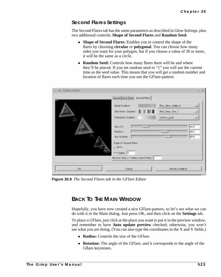
C h a p t e r 3 5
e,
tand
can
w,
lds.)
the
Second Flares SettingsThe Second Flares tab has the same parameters as described inGlow Settings, plustwo additional controls:Shape of Second Flares andRandom Seed.
• Shape of Second Flares: Enables you to control the shape of theflares by choosingcircular or polygonal. You can choose how manysides you want for your polygon, but if you choose a value of 30 or morit will be the same as a circle.
• Random Seed: Controls how many flares there will be and wherethey’ll be placed. If you set random seed to “1” you will use the currentime as the seed value. This means that you will get a random numberlocation of flares each time you use the GFlare-pattern.
BACK TO THE MAIN WINDOW
Hopefully, you have now created a nice GFlare-pattern, so let’s see what wedo with it in the Main dialog. Just press OK, and then click on the Settingstab.
To place a GFlare, just click at the place you want to put it in the preview windoand remember to haveAuto update preview checked; otherwise, you won’tsee what you are doing. (You can also type the coordinates in the X and Y fie
• Radius: Controls the size of the GFlare.
• Rotation: The angle of the GFlare, and it corresponds to the angle of Gflare keystones.
Figure 35.9 The Second Flares tab in the GFlare Editor
T h e G i m p U s e r ’ s M a n u a l 5 2 3

L i g h t E f f e c t F i l t e r s
r
m
l
t-
me-get
• Hue Rotation: Controls the color of a GFlare.
• Vector angle: Controls the direction of theSecondary flares indegrees.
• Vector Length: Controls the length of the Secondary flares.
• For a explanation ofAdaptive Supersampling, see “The Blend Tool OrGradient Fill” on page 131. Basically, it makes your gradients smoothewhen they go from one color to another.
GFlare allows you tocreateandsavedifferent GFlare-patterns and then use theat the appropriate moment, just by choosing them in the Selector tab.
Tip: Just remember to create aGFlare directory where your GFlare-patterns wilbe saved and make sure you specify the path in yourgimprc file; otherwise, itwill fail. (See “Gimp Start Flags And rcfiles” starting on page 785.)
LIGHT EFFECTS
If you want to try some traditional light effects like lighting up a wall with a spolight, Light Effects is the filter to use.
THE MAIN INTERFACE
In the main interface ofLight Effects you’ll find a preview window and atab folder forOptions, Light andMaterial .
To look at what you’re doing, you must first press thePreview button. There’sno auto-preview because that would slow things down. Every time you do sothing with this filter, like changing a parameter, you need to press Preview toa grip of what’s happening (don’t forget this). You can alsozoomthe preview bypressing+ or -.
Before After
Figure 35.10Before andafter applyingGFlare
5 2 4 T h e G i m p U s e r ’ s M a n u a l
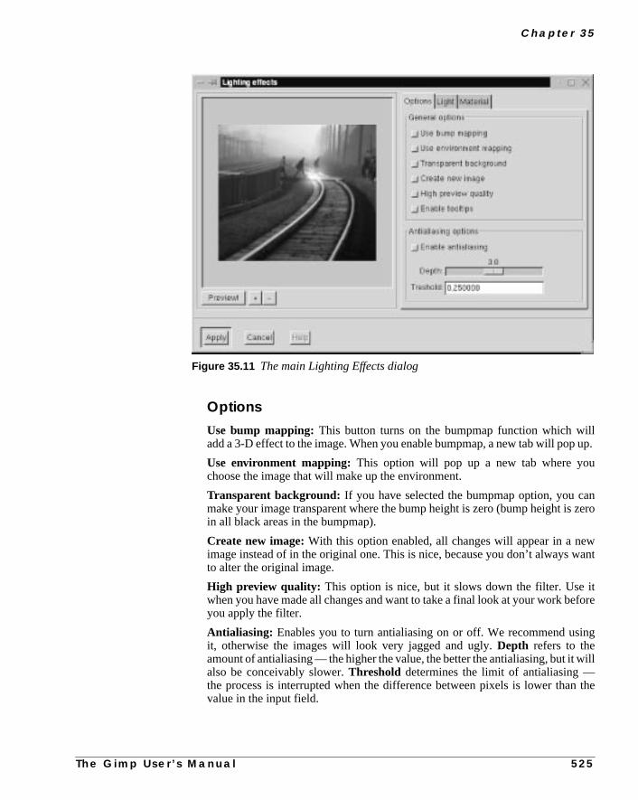
C h a p t e r 3 5
llup.
nzero
want
tfore
ng
will
the
OptionsUse bump mapping: This button turns on the bumpmap function which wiadd a 3-D effect to the image. When you enable bumpmap, a new tab will pop
Use environment mapping: This option will pop up a new tab where youchoose the image that will make up the environment.
Transparent background: If you have selected the bumpmap option, you camake your image transparent where the bump height is zero (bump height isin all black areas in the bumpmap).
Create new image:With this option enabled, all changes will appear in a neimage instead of in the original one. This is nice, because you don’t always wto alter the original image.
High preview quality: This option is nice, but it slows down the filter. Use iwhen you have made all changes and want to take a final look at your work beyou apply the filter.
Antialiasing: Enables you to turn antialiasing on or off. We recommend usiit, otherwise the images will look very jagged and ugly.Depth refers to theamount of antialiasing — the higher the value, the better the antialiasing, but italso be conceivably slower.Threshold determines the limit of antialiasing —the process is interrupted when the difference between pixels is lower thanvalue in the input field.
Figure 35.11 The main Lighting Effects dialog
T h e G i m p U s e r ’ s M a n u a l 5 2 5

L i g h t E f f e c t F i l t e r s
t as
e
LIGHT
You can set theType of light, the Light color and thePosition of the lightsource.
Type Of Light
• Point light is a sort of spotlight that shines straight onto your image.
• Directional Light is a softer point light (more like a normal lamp inthe ceiling).
• Spot light is harder and more focused than point light.
Light ColorTo set the color of the light, press theLight source Color button to access theSelect light source color dialog. Here you can select a suitable light color, jusyou would in the Color Select dialog in the toolbox.
Position For Point LightThere are three coordinates for controlling light position —X,Y andZ:
• TheX-coordinate moveshorizontally from -0.5 to 1.5, where -0.5 isthe left-hand position, and 1.5 is the right-hand one.
• The same goes for thevertical Y-coordinate; -0.5 is at the top and 1.5is at the bottom.
• Z is thedepth of the light, where 0 would be the flat surface of thecomputer monitor. There is no upper limit for this coordinate. There arno limits for X and Y either; the values are only recommendationsfrom us.
Figure 35.12 The Light tab
5 2 6 T h e G i m p U s e r ’ s M a n u a l

C h a p t e r 3 5
ction
ke it
max/
tt
getue.ll
MATERIALS
You can specify the appearance of the rendered light to give an image or selematerial characteristics.
You do this by controlling theIntensity Levels and Reflectivity parameterfields. The littlespheres represent the properties of the material.
Low values make the material looks like the left sphere, and high values malook like the sphere to the right.
The values specified at the end of each paragraph that follows are suggestedmin values.
Intensity Levels
• Ambient can be described as the intensity of the surrounding light thashines on the object. The brightest areas will not change intensity, budarker areas will get lighter as you increase this value. Think of yourholiday snapshots, where very intense sunlight will produce bright andcontourless features with very pale shadows(0.1 -> 3.0).
• Diffuse can be described as the intensity of the directional light thatshines on the object. The darkest (shadow) areas of the object never darker, but brighter areas turn brighter as you increase the Diffuse valThis is like the difference between cloud shadow and sunlight, or a duand a shiny object (0.5 -> 3.0).
Figure 35.13 The Materials tab
T h e G i m p U s e r ’ s M a n u a l 5 2 7

L i g h t E f f e c t F i l t e r s
ct
,tice
e
ft,
willerer,
t
at
and
can
Reflectivity
• Diffuse controls the contrast and distribution of light between the objeand the reflection highlight. The mid-values are affected with thisparameter. The glossier an object is, the darker the mid-values will bebecause the contrast with the highlight spot will be greater. A dull/plasobject will have little highlight contrast in real life, so don’t set this valutoo high if that is the effect you wish to achieve (0.2 -> 0.9), with a nicevalue around 0.5.
• Specular controls the brightest values, or the sharpness/softness of thhighlight, because a brighter highlight will have greater contrast to themid-values. A glossy/metallic object will have bright highlights withsharper edges, and dull objects will have a dull, if any, highlight with soblurry edges(0.4 -> 0.6).
• Highlight controls the size of the highlight by changing the relationbetween the brightest/darkest areas and the mid-values. Higher valuesmake the highlight smaller, with a smoother mid-value distribution. Lowvalues will make it larger, and the darkest shadow areas will also be largwhich means that the transition from bright to dark will be more abrup(15 -> 50, but around 20 -> 30 is best).
BUMPMAPPING
Bumpmap is similar to “Bump Map” on page 540, so it’s a good idea to check thpassage out before you start. You can only usegrayscaleimages as bumpmaps, soif you want to bumpmap against the original image, you have to duplicate itchange it to grayscale mode in the image menu.
You can set the bump curve toLinear , Logaritmic , Sinusoidal or Spheri-cal. Look at the curves in the bumpmap filter to appreciate the difference. Youalso specify the maximum and minimum height/depth of the bumpmap.
Figure 35.14 The Bump tab
5 2 8 T h e G i m p U s e r ’ s M a n u a l

C h a p t e r 3 5
d in
aron-lect
ing
, as
n
ENVIRONMENT MAPPING
If you use environment mapping, you’ll get the opportunity to place yourobject in a setting of your own choice. You can choose from all images openeGimp, regardless of size and shape.
Environment Mapping will make the image you created look like it’s insidesphere, and the inner surface of this sphere is covered with the distorted enviment image. Light is reflected from the sphere, and the image inside will refthe environment mapping.
A SIMPLE TUTORIAL
1. Create a new grayscale image (256x256) with a black background by usright-click|File| New or File| New.
2. Bring up theText tool in the toolbox and type a white 200 pixel “G” withthe Utopia font. Place the white letter in the middle of the grayscale imageshown in Figure 35.15.
3. Create a new RGB image of 256x256 pixels.
4. Bring up theBlend tool from the toolbox and select to blend with acustomgradient from the Gradient Editor.
5. Open the Gradient Editor with theright-click|Dialogs|Gradient Editor command, and choose German Flag Smooth (if youhaven’t changed the settings ingimprc, German Flag Smooth is the defaultgradient).
6. Apply a linear gradient from the left to the right in the RGB image, as showin Figure 35.16.
7. Bring up theLighting Effects filter from the RGB image.
Figure 35.15 The grayscale G Figure 35.16 The RGBimage
T h e G i m p U s e r ’ s M
a n u a l 5 2 9
L i g h t E f f e c t F i l t e r s
ment
nce
8. CheckUse bump mapping andUse environment mapping in theOptions tab folder and pressPreview. (If there are other opened images inyour Gimp session, first make sure that you use the RGB image as environmap and the grayscale image as bumpmap.)You should now have a nicebumpmapped and highlighted G (Figure 35.17).
9. CheckTransparent background. You will now see your G floating in atransparent surrounding Figure 35.18 .
10. Uncheck the environment mapping, press Preview and look at the differe(Figure 35.19).
11. Now, bring up the Alien Map filter withright-click|Filters|Color| Alien Map from the RGB image. Apply the default values.
12. CheckUse environment mapping, press Preview in the Lighting Effectsdialog, and you’ll get a brand new color gradient.
Figure 35.17 The G has now beenbumpmapped into the RGB image
Figure 35.18 With a transparentbackground
Figure 35.19 Withoutenvironment mapping
5 3 0
T h e G i m p U s e r ’ s M a n u a l
C h a p t e r 3 5
rialr to
Test different types of light sources and light colors and different kinds of matereflections, and watch the difference here with Directional light (just remembepress Preview).
Figure 35.20 Differentcurve settings
Linear
Logarithmic Sinusoidal
T h e G i m p U s e r ’ s M a n u a l 5 3 1

L i g h t E f f e c t F i l t e r s
Thisoubutreenpar-
SPARKLE
With Sparkle you can addsparklesto your image and get a frosty, glittery feelingto an object.
USING SPARKLE
Sparkle will select the brightest parts of your picture and put a sparkle there.behavior can make it rather difficult to predict where the sparkles will go. If ytry it in a selection, you will get more control over where the sparkles end up,The best way is generally to use a transparent layer (or a black layer + scmode) where you put tiny white spots. This way, you can make sure that the skles will only appear where you want them to be.
Figure 35.21 Differentmaterial and light settings
Ref: Diffuse 0.8
Ref: Specular 0.9 Point Light
5 3 2 T h e G i m p U s e r ’ s M a n u a l

C h a p t e r 3 5
et aowts
allyant
nd
ould
thed to
f
PARAMETERS
• TheLuminosity Threshold controls theamount or density ofsparkles. It computes the luminosity values of all pixels and selects thbrightest pixels to be the center points of the sparkles. Just how brighpixel has to be to create a sparkle is determined by this threshold. A lvalue (like 0.001) will probably only produce sparkles at very bright parof your image, because only 1% of all pixels will be considered brightenough, and the flares will also be rather thin and small. There is generno reason to use a higher Threshold value than 12%, even when you wa lot of sparkles. High values increase processing time enormously, ausually only result in big white blotches in the image.
Note: One decimal too many snuck into this parameter’s slide bar - 0.001 shread 0.01 or 1%.
• Flare Intensity: Determines the light intensity of the flare around thestars. If your sparkles look hard and unnatural, you have obviously setFlare Intensity too high, and if you can hardly see the spikes, you neeincrease this value.
Figure 35.22 Before and after applying Sparkle. Notice the small white dots in theBefore image. This is how you effectively control where your sparkles end up. The size othe sparkles depends on the size of the dots.
Before Result
T h e G i m p U s e r ’ s M a n u a l 5 3 3

L i g h t E f f e c t F i l t e r s
lyar
. Ifsite
r
thehen
ernt
cal,on
ex
• Spike Length: Controls the length of the star spikes. Note that theminor spikes start fading almost immediately, while the major spikes onstart to fade away after a number of initial pixels with the same or similvalue to the center pixel.
• Spike Points: Specifies how many spikes will radiate from a pixel.Five spike points will produce five major spikes, and five minor spikesyou use an uneven number of spikes, major spikes will be placed oppominor spikes. For even numbers, a major spike will meet with anothermajor spike.
• Spike Angle: The angle of the first major spike and the horizontal axisof the star. If it’s set to zero, that spike will be horizontal, and the othespike points will be evenly distributed around the star’s center. A 90degree spike angle will produce a vertical spike, and so on. If you set Spike Angle to -1, you will get a randomly chosen spike angle for eacspike point. As each pixel within the threshold range produces the givnumber of spikes, almost all of those spikes will be visible if you userandom spike angles. When you use a fixed angle, the many spikes inbright pixel clusters will arrange themselves almost on top of each othso that the cluster will appear as one big, bright star with a limited amouof spikes. The result of a random spike angle is more organic than optimeaning that a sparkle created with random angles has more in commwith a dandelion seed or cobweb cluster than with the geometrical reflfrom a crystal or lens.
Figure 35.23 The Sparkledialog
5 3 4 T h e G i m p U s e r ’ s M a n u a l

C h a p t e r 3 5
fre
theall
ir
cannd
heintsor
ing
the
ndks of
• Spike Density: Does not control the number of spikes, but the numberof sparkles or stars. If you set Spike Density to 0.50, only 50 percent othe chosen pixels will produce a sparkle. Note that those 50 percent achosen randomly; bright pixels are not favored.
• Preserve Intensity: Controls how much of the original intensity in thecenter pixel should be preserved. In practice, this means that loweringPreserve Intensity value will increase the intensity of the stars, becausecenter pixels will get maximum intensity (when PI=0), regardless of theoriginal value.
• Opacity: Adjusts the opacity of the stars. As you lower this value, thesparkles will successively get more and more transparent, so that yousee what’s in the layer beneath. If you’re using a single background aalpha is not enabled in your image, lowering this value will reducesaturation and value in the stars, making them look dull and dark.
• Random Hue andSaturation: Add a color shift to your sparkles, but itwill only be visible if the sparkle color was heavily saturated from thestart.
• Inverse: Reverses the sparkle effect so that instead of searching out tbrightest pixels, the darkest pixels will be found and used as center poof black stars. Because black or dark star clusters tend to look like hairgrass rather than sparkles, you can get quite amusing results by runnthis filter with the inverse button checked.
• Add Border: Draws a border of spikes around the image, giving it aninteresting feathered edge. The softness of the edge is determined byFlare Intensity and Preserve Intensity parameters.
• Spike Color Settings: Allow you to choose another sparkle colorthan the natural colors found in the image. You can use theForegroundColor or theBackground Color in the toolbox to tint your sparkles.The added color will appear as if in Screen mode for normal settings, ain Multiply mode for Inverse. However, if the chosen color is bright/darenough, the chosen color will just appear at the semi-transparent edgethe white/black sparkles.
T h e G i m p U s e r ’ s M a n u a l 5 3 5

L i g h t E f f e c t F i l t e r s
likelor
thehen
log.
gridut
SUPER NOVA
TheSuper Novaplug-in creates a big shinysuper novain your image. TheR,GandB slides determine the color of the super nova. You specify the color justin the Color Selection dialog (which you access by clicking in one of the coswatches in the toolbox).
The problem is that you can’t see what the color looks like until you applyplug-in. We suggest that you open the color dialog and choose a color there. Wyou’re happy with the color, type those RGB values in the Super Nova diaRadius is the radius of the inner part of the nova (the star part).Spokesdeter-mines how many spokes the nova will get. You place the nova with the cursorin the preview image (you can also type the coordinates in the X and Y inpfields).
Figure 35.24 The Super Nova dialog
Figure 35.25 Before and after Super Nova
5 3 6 T h e G i m p U s e r ’ s M a n u a l

C h a p t e r 3 5
T h e G i m p U s e r ’ s M a n u a l 5 3 7


C H A P T E R
36 Map FiltersThere are many ways to use maps. If you want tobend text along a curve, you have to use adisplacement map. To create 3-D effects you use abumpmap. All of the Gimp map filters will bediscussed in this chapter.

M a p F i l t e r s
eled
e
the
any
f the
singlsand
BUMP MAP
Bump Map works byembossingan image, andmappingthis relief to anotherimage. This will create a 3-D effect in the second image, just as if you had modit in clay.
BUMP MAP AND EMBOSS
First read aboutEmbossin “Distort Filters” starting on page 459 to understand thconcepts ofAzimuth , Evaluation andDepth.
There are many differences between Bump Map and the bumpmap option inEmboss plug-in. First of all, inEmboss bumpmap, you can’t specify a mapimage (see map image in Figure 36.2).
The Bump Map plug-in has more options than Emboss, and you can bumpmaptype of image. Emboss only works for RGB images without alpha.
HOW TO USE BUMP MAP
Because you can bumpmap any image, you may have to adjust the position obackground bumpmap. To do so, use theX andY offset slides. You may alsowant to compensate for the loss of luminance resulting from embossing by uthe Compensate for darkening button. Because Emboss raises light pixeand carves dark pixels, it’s quite simple to reverse so that otherwise darkcarved parts of your map will turn light and raised. To achieve this, checkInvertbumpmap.
Figure 36.1 TheBump Map dialog
5 4 0 T h e G i m p U s e r ’ s M a n u a l

C h a p t e r 3 6
hrved
xels,arentvel
n dif-f the
TheAmbient slide controls the amount of ambient light in your image. A higlevel of ambient light will make all shadows disappear, and the raised and caparts will be less apparent.
Waterlevel only becomes relevant if there arealpha valuesor transparency inthe map image. Transparent pixels in a map image will be treated as dark piand therefore become carved. If you slide the Waterlevel up to 255, the transppixels will be flattened and turn invisible, just as if you had raised the water lein a pond.
If you check theInvert bumpmap radio button, they will be treated as light pix-els and get raised, but Waterlevel will flatten that, too.
Linear map, Spherical map and Sinusoidal map are the three bumpmaptypes used to create a 3-D model. Figure 36.3 shows the relationship betweeferent map modes, and how they raise/carve in relation to the luminance opixels.
Image to bumpmap
Map image Result
Figure 36.2 An image and amap image are the two elementsnecessary to create a bumpmap
T h e G i m p U s e r ’ s M a n u a l 5 4 1

M a p F i l t e r s
atelf.
tal
is-
fil-
.
COORDINATE MAP
The Coordinate Map filter does the same thing as theDisplace filter(described in the next section). The creator of this filter writes that CoordinMap is easier to use, and maybe he’s right — you will have to try it for yourseThere is one limitation though,it will only work with 256x256 pixel images.
Here is how it works: The plug-in will map two images (one in the horizondirection, and one in the vertical direction) on asourceimage. The source imagewill get the architecture from themap images. Read about theDisplacefilter andyou will understand the Coordinate Map filter, too.
DISPLACE
Displaceis a general distort filter, which can be used for nearly all kinds of dtortion. You can, for example, use it towhirl, pinch, shift, spreador melt yourimage. We will try to give you a short introduction to the hidden secrets of thister.
Height
Depth
Linear
Spherical
Sinusoidal
Dark Light
Figure 36.3 These images illustrate the difference between the three maptypes
Linear Map
Spherical Map
Sinusoidal Map
Figure 36.4 Atext string wasdisplaced alongthe roof line ofthe Chevelle
5 4 2 T h e G i m p U s e r ’ s M a n u a l

C h a p t e r 3 6
n
ntroluse
ce-sim-
cale
d
127s-ite
k ofomesneg-her
-128
one
ce inand
HOW DOES IT WORK?
It is clear that this filter willdisplacean image or part of an image; the questiois how? To put it simply, the Displace filter needs adisplacement mapto tellit how to distort the image. The brightness or darkness values in this map cohow Displace moves the image pixels. To make displacement easy, alwaysgrayscaleimages as maps. It will work with colored images too, but as displament depends on the brightness/darkness of the map, the color information isply not used.
Summary
• Use grayscale images as displacement maps.
• The amount of displacement is based on the brightness/darkness ofthe map.
CALCULATIONS
As we know from earlier chapters, you can use 256 shades of gray in a graysimage. How bright or dark a gray “color” is depends on theIntensity value,which goes from 1 (black) to 256 (white). In the middle of this range we fin“medium gray,” with a value of 128.
One of the fundamental parts of displacement is that the “dark values” 0 towill be displaced in one direction, the “medium gray” value 128 will not be diplaced at all, and the “light values” 129 to 256 will be displaced in the opposdirection of the dark values.
To make things easier we can put this range in a new perspective. If you thin-128 as total darkness, 0 as medium gray and +128 as total lightness, it becmore clear that displacement will go in different directions, because we haveative and positive intensity in our map. The maximum displacement in eitdirection happens where the map has a value of either -128 or +128.
Summary
• Displacement is based on a brightness/darkness scale, ranging from to +128.
• There will be no displacement where the value is 0.
• The displacement goes in two directions. Negative values displace in direction, and positive values displace in the opposite direction.
THE USER INTERFACE
Let’s take a closer look at the user interface. As you can see, you can displaboth X and Y directions. You can also set how much you want to displace,
T h e G i m p U s e r ’ s M a n u a l 5 4 3
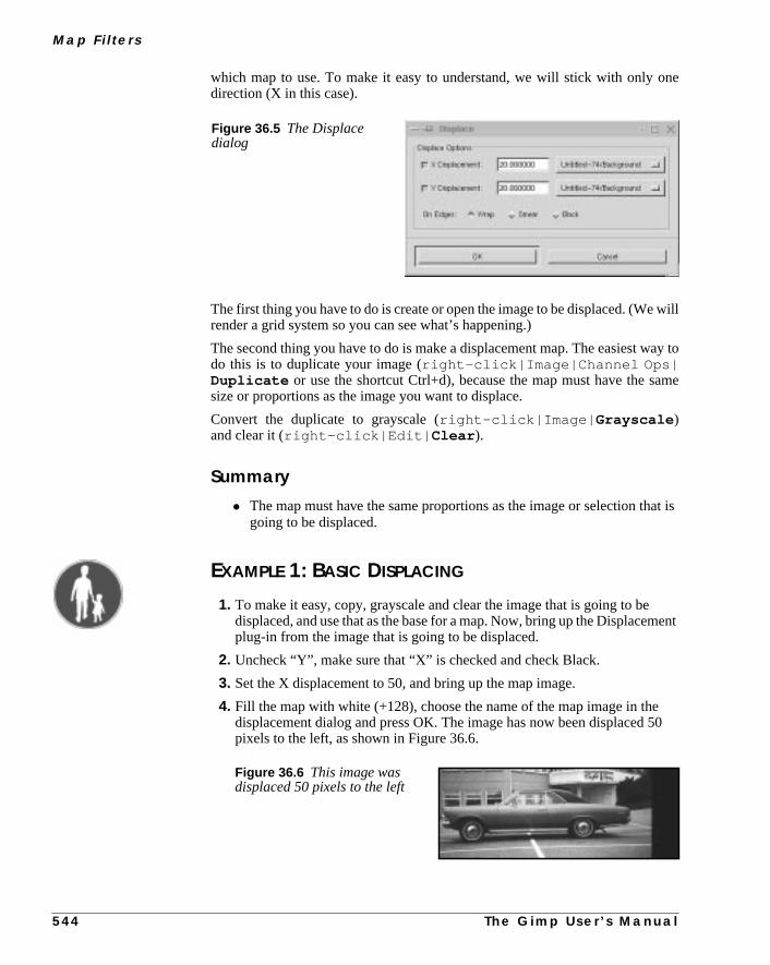
M a p F i l t e r s
ne
will
ay to
ame
at is
ment
50
which map to use. To make it easy to understand, we will stick with only odirection (X in this case).
The first thing you have to do is create or open the image to be displaced. (Werender a grid system so you can see what’s happening.)
The second thing you have to do is make a displacement map. The easiest wdo this is to duplicate your image (right-click|Image|Channel Ops|Duplicate or use the shortcut Ctrl+d), because the map must have the ssize or proportions as the image you want to displace.
Convert the duplicate to grayscale (right-click|Image| Grayscale )and clear it (right-click|Edit| Clear ).
Summary
• The map must have the same proportions as the image or selection thgoing to be displaced.
EXAMPLE 1: BASIC DISPLACING
1. To make it easy, copy, grayscale and clear the image that is going to bedisplaced, and use that as the base for a map. Now, bring up the Displaceplug-in from the image that is going to be displaced.
2. Uncheck “Y”, make sure that “X” is checked and check Black.
3. Set the X displacement to 50, and bring up the map image.
4. Fill the map with white (+128), choose the name of the map image in thedisplacement dialog and press OK. The image has now been displacedpixels to the left, as shown in Figure 36.6.
Figure 36.5 The Displacedialog
Figure 36.6 This image wasdisplaced 50 pixels to the left
5 4 4 T h e G i m p U s e r ’ s M a n u a l

C h a p t e r 3 6
ckn in
e28nt
28
to
e
e
5. Now press Ctrl+z and do it again, but this time with a map that is totally bla(-128). The image has now been displaced 50 pixels to the right, as showFigure 36.7.
6. Let’s do this with a map with a value of +64 (a gray with the Intensity valu191). This will displace the image 25 pixels to the left because (64 x 50)/1is 25, which leads to the following algorithm: (value (of gray) x (displacemevalue))/128 equals the amount of displacement (Figure 36.8).
7. Positive values will displace to the left, and negative to the right. Moreexamples: Gray value: -64 (dark) Displacement value: +50 -> (-64 x 50)/1= -25 -> 25 pixels displacement to the right. Gray value: +64 andDisplacement value: -50 -> (64 x -50)/128 = -25 -> 25 pixels displacementthe right.
Summary
• If you have positive “X” displacement values, a bright map will displacto the left and a dark to the right.
• The amount of displacement is based on this algorithm: (value xdisplacement)/128 = displacement in pixels, positive to the left andnegative to the right.
• The above is also true for Y direction displacement, you just have toswitch left to top and black to bottom.
• If you have positive “Y” displacement values, a bright map will displacto the top of the image and a dark to the bottom of the image.
• The amount of displacement is based on this algorithm: (value xdisplacement)/128 = displacement in pixels, positive to the topand negative to the bottom.
Figure 36.7 This image wasdisplaced 50 pixels to the right
Figure 36.8 This image wasdisplaced 25 pixels to the left
T h e G i m p U s e r ’ s M a n u a l 5 4 5

M a p F i l t e r s
canis-akene
, so
ayookself.
ar,dient
d the
EXAMPLE 2: DISPLACING IN TWO DIRECTIONS
Now we move to more complex displacement. As you see in the dialog, youdisplace in bothX andY directions. This means that you can, for example, dplace the image towards the bottom-left corner. To achieve this, you have to mtwo maps, one white and one black. Map the black one to Y and the white oto X. Your image will now be displaced toward the bottom-left corner (Figure 36.9).
EXAMPLES 3 AND 4: SPREADING AND CURVING
We said earlier that you can achieve any kind of distortment with this plug-inwe will give you two more examples:
Spread horizontal: Create a map made of horizontal black, white and grstripes. The different intensities of the stripes will make the displaced image las if you have spread it in horizontal ribbons. You have to experiment by yourto figure out what you can do, but trust us — you can do a lot with this plug-in
Curving Text: The obvious example is to bend text over something circulsuch as a terrestrial globe. To achieve that, you’ll have to create a suitable gra(dark at both ends and light in the middle) with theGradient Editor . In Figure36.10 we have created a displacement map that will make the text flow arounshape of the car.
Figure 36.9 This image wasdisplaced both vertically andhorizontally
5 4 6 T h e G i m p U s e r ’ s M a n u a l

C h a p t e r 3 6
younte
he
lacknders, but
r
Using Transparency In Map ImagesSometimes, it’s hard to create the kind of map you want, for example, whenonly want to displace part of your image. When you experiment with differemaps, you’ll often want to darken/lighten them, but this will inevitably alter thmedium gray value.
The perfect 0 will be transformed to something that will displace your image. Tway to get around this problem is to make the static parts of your maptranspar-ent, because fully transparent pixels are treated as if they had a value of 0. Bpixels, which are (almost) transparent, are treated as having a value of a bit u0, or somewhere around (-5). The same goes for semi-transparent white pixelthey will get a positive value around (+5), soalpha valuesshould play a veryimportant part in your map making.
Figure 36.10 How to make a textbend along a curve
This practical example explains thetheory of basic displacement prettywell
A two-layered image: the Chevelle in the background layeand the text in layer one
The Y displacement map
The final outcome after a few calculations
T h e G i m p U s e r ’ s M a n u a l 5 4 7

M a p F i l t e r s
antleft,
ssthe
ate
ap2 innsityalsoour
l
ixel
What Are Black, Smear And Wrap Good For?Say that you’re using a white map, a displace value of 50 and that you only wto displace in the X direction. When the image is displaced 50 pixels to thethere will be 50 pixelsmissing at the right side of the image.
If you checkBlack, a black color will fill this part for you. If you checkSmear,those 50 pixels will be stretched from the right part of the image. If you preWrap , the 50 pixels you pushed out of the frame at the left side will appear atright side of the image to cover for the missing pixels.
HOW TO CALCULATE WHERE A PIXEL WILL END UP
Let’s choose a pixel that is positioned at 50(x) and 50(y) in the image coordinsystem.We go to ourmapsand check theIntensity value of the equivalent pixelin that position. In this case we presume that the Intensity value we got from mX (the horizontal displacement map) was 230, which means (230 - 128) = 10the displacement range. Map Y (the vertical displacement map) had an Intevalue of 55, which means (55 - 128) = -73 in the displacement range. Wechoose a displacement value of 50 for X and 30 for Y. If we put these values inalgorithm.
• (102 x 50)/128 = 39.84, which is the displacement of map X (the pixelwill displace 40 pixels to the left).
• (-73 x 30)/128 = -17.11, which is the displacement of map Y (the pixewill displace 17 pixels downwards).
These calculations tell us that our pixel will end up at x=10 and y=67, i.e., the pwill be moved a bit closer to the bottom-left corner.
Figure 36.11 The differencebetween Smear and Wrap
Smear
Wrap
5 4 8 T h e G i m p U s e r ’ s M a n u a l

C h a p t e r 3 6
actal
eam-
ia-u
t thisfor
arts
FRACTAL TRACE
Fractal Trace distorts your image using aMandelbrot fractal. It does this bymapping your image to the fractal, as in Figure 36.12
FRACTAL TRACE AND FRACTAL EXPLORER
Five parameters control the Mandelbrot fractal;X1, X2, Y1, Y2 andDEPTH.For a better understanding of these parameters, read about fractals in “FrExplorer” on page 595.
X(Y)1 and X(Y)2 correspond to the X(Y)min and X(Y)max parameters in thmain Fractal Explorer dialog, and DEPTH is the same as the ITER(ations) pareter.
Note that the default value for DEPTH (3) is much lower in the Fractal Trace dlog than the default value for ITER in the Fractal Explorer dialog (50). If yoincrease the depth value, you’ll map your image to a classic fractal shape, buwill yield less spectacular effects than using lower values (the opposite is trueFractal Explorer).
OUTSIDE TYPE
This option lets you choose between four different backgrounds to cover up pthat were displaced by the fractal mapping. This works the same as theOn Edgesoption in theDisplacefilter; read more about it in “What Are Black, Smear AndWrap Good For?” on page 548.
Figure 36.12 The Fractal Trace dialog and an example of how the filter can be used
T h e G i m p U s e r ’ s M a n u a l 5 4 9

M a p F i l t e r s
thethe
ur
cre-
rinal
ig-age,d or
id-nalf this
Note that to be able to use theTransparent option, you have to have analphaenabledimage. To make it so, selectright-click|Layers| Add AlphaChannel before applying the Fractal Trace filter.
ILLUSION
Illusion duplicates your image (x) times, and puts them in a circle aroundcenter of the original image. The surrounding images are superimposed onoriginal, so it looks a bit blurry or ghostlike.
The only option in this filter is how many (x) copies you want to apply to yoimage. Another word for this filter iskaleidoscope,which is a quite accuratedescription of what it does.
MAKE SEAMLESS
The Make Seamlessplug-in prepares an image fortiling by creating seamlessedges. This filter does away with all those ugly edges, and it’s an easy way toate good-looking patterns.
If you want to create aseamless patternas a background for your desktop oin a web page, this is (often) the best tool to use. Note that the center of the origimage will constitute the only focused part of the new image. Mirrors of the orinal image are placed in the center and in all four corners of the seamless imand those mirrors blend together at the edges, causing it to look a bit blurredouble-exposed in those areas.
If an important part of your image (like a face) is somewhere other than in the mdle, you may have to do some correction work by copying parts of the origiimage and pasting them into the seamless image. If you feel that the result ofilter is too soft or blurred, try to correct your image with theOffset command inthe Image menu. Read more about it in “Offset” on page 294.
Figure 36.13 The kaleidoscope effect that Illusion produces was used toillustrate the nine lives of this cat
Before After
5 5 0 T h e G i m p U s e r ’ s M a n u a l

C h a p t e r 3 6
byforball.nly
stings
MAP OBJECT
The Map Object filter will map your image to asphere, a plane, a box or acylinder. You can also apply differentlighting effects to the mapped objectto make it even more convincing.
You can even specify the properties of the “material” in the mapped objectchanging the values for intensity and reflectivity. This is a very nice plug-increating 3-D-effects in Gimp. You can, for example, create a perfect soccerThere are, of course, many more applications for this excellent plug-in — the olimit is your imagination.
MAIN INTERFACE
In the main interface there is apreview window and tab forOptions, Light ,Material andOrientation . To be able to see what you’re doing, you must firpress the Preview button (there’s no auto-preview because that would slow thdown).
Figure 36.14 Theseexamples show thedifference betweentiling a pattern withand without MakeSeamless
T h e G i m p U s e r ’ s M a n u a l 5 5 1

M a p F i l t e r s
time.
.
loty a
ip
sed
It is a good idea to useShow preview wireframe. Then, your object will bedisplayed as a wireframe, and you can see your actions take place in realWhenever you need to take a good look, just pressPreview. You can alsozoomthe preview by pressing+ or -.
OptionsYou can choose to map to aplane, asphere, abox or acylinder. If you chooseto map your image to a box or a cylinder, a new tab will appear calledBox andCylinder . See “Box And Cylinder” on page 557 for information on this folder
• Transparent background results in a transparent surrounding (thedrawable will turn transparent outside of the object).
• Tile source image means that the source image will be repeated ortiled to extend the map object (plane) into infinity. For example, if youmap to a plane and this plane is tilted in some direction, there will be aof space around the output image. Instead of having this space filled bbackground color or transparency, the plane will tile itself, filling theentire output image.
• Create new image preserves the original image, creating a duplicateimage where the filter takes effect.
• Enable tooltips is a nice option. When you get to know the filter andalready know what the tooltips are all about, you can disable the tooltmessages by unchecking this option.
• The Enable Antialiasing option enables you to turn antialiasing on oroff, but we recommend you use it; otherwise, the images will look veryjagged and ugly (there can of course be moments when a non-antialiaimage can be useful).Depth refers to the amount of antialiasing — the
Figure 36.15 Map Object’smain dialog
5 5 2 T h e G i m p U s e r ’ s M a n u a l

C h a p t e r 3 6
dt
higher the value, the better the antialiasing, but it will also be slower.Threshold determines the limit of antialiasing, the process is interruptewhen the difference between pixels is lower than the value in the inpufield.
Figure 36.16 The Map Object filter offers avariety of 3-D objects for mapping your image.You only have to take a look at these examples torealize that you can create awesome imageswith this filter.
Original
BoxCylinder
SpherePlane
T h e G i m p U s e r ’ s M a n u a l 5 5 3

M a p F i l t e r s
o
di-andt them-
ttlend
and
lht.
LIGHT
You can set thetype of light, the light color and theposition of the lightsource, and if you have chosenDirectional Light , you can also set theangleof the light source.
Light SettingsPoint light is a sort of spotlight which shines straight onto your image.Direc-tional light is a softer point light (more like a normal lamp in the ceiling). Tset the color of the light, simply pressLightsource Color.
There are three coordinates for positioning point light: X,Y and Z. The X coornate moves horizontally from -0.5 to 1.5, where -0.5 is the left-hand position,1.5 is the right-hand one. The same goes for Y; -0.5 is at the top and 1.5 is abottom. Z is the depth of the light, where 0 would be the flat surface of the coputer monitor.
There is no upper limit for this coordinate, but if you exceed a value of 5, a liblue dot shows up on the image. You can grab this dot with the cursor achange the position of the light source by dragging (there are no limits for XY either — the values are only recommendations from our side).
MATERIAL
You can control different materials’Intensity and Reflectivity. The littlespheres represent thepropertiesof the material. Low values make the materialook like the left sphere and high values make it look like the sphere to the rig
Figure 36.17 The Light tab
5 5 4 T h e G i m p U s e r ’ s M a n u a l

C h a p t e r 3 6
sted
tt
getue.en
ct
,tice
.
The values specified at the end of each of the following paragraphs are suggemax/min values.
Intensity Levels
• Ambient can be described as the intensity of the surrounding light thashines on the object. The brightest areas will not change intensity, budarker areas will get lighter as you increase this value. Think of yourholiday snapshots, where very intense sunlight will produce bright andcontourless features with very pale shadows(0.1 -> 3.0).
• Diffuse can be described as the intensity of the directional light thatshines on the object. The darkest (shadow) areas of the object never darker, but brighter areas turn brighter as you increase the Diffuse valThis is like the difference between cloud shadow and sunlight, or betwea dull and a shiny object(0.5 -> 3.0).
Reflectivity
• Diffuse controls the contrast and distribution of light between the objeand the reflection highlight. The mid-values are affected with thisparameter. The glossier an object is, the darker the mid-values will bebecause the contrast with the highlight spot will be greater. A dull/plasobject will have little highlight contrast in real life, so don’t set this valuhigh if that is the effect you want to achieve(0.2 -> 0.9 with a nice valuearound 0.5).
Figure 36.18 The Material tab
T h e G i m p U s e r ’ s M a n u a l 5 5 5

M a p F i l t e r s
e
ft,
willerer,
t
lueser
• Specular controls the brightest values, or the sharpness/softness of thhighlight, because a brighter highlight will have greater contrast to themid-values. A glossy/metallic object will have bright highlights withsharper edges, and dull objects will have a dull, if any, highlight with soblurry edges(0.4 -> 0.6).
• Highlight controls the size of the highlight by changing the relationbetween the brightest/darkest areas and the mid-values. Higher valuesmake the highlight smaller, with a smoother mid-value distribution. Lowvalues will make it larger, and the darkest shadow areas will also be largwhich means that the transition from bright to dark will be more abrup(15 -> 50, but around 20 -> 30 is the best).
ORIENTATION
The best way to understand this tab is to bring up thewireframe preview andplay around. It will take you less than a minute to learn it.
X, Y and Z pos. move the drawable, just likeOffset in the Image menu. Theoption name stands for the position of the center of the image.
The default center value of the X and Y directions is 0.5.
For the Z direction, 0 is the center value (1 is maximal zoom, and negative vais “away from you”) there is no limit for the negative scale (but for values und-60 you will probably not see anything).
XY controls theY rotation around theZ axis,YZ controls theZ rotation aroundtheY axis andXZ controls theZ rotation around theX axis.
Figure 36.19 The Orientation tab
5 5 6 T h e G i m p U s e r ’ s M a n u a l

C h a p t e r 3 6
eachn and
BOX AND CYLINDER
This tab is only available if you choose to map against abox or cylinder. Thereare several drop-down menus where you can choose a different image forside of the box, or top/bottom the cylinder. This makes it quite easy to desigvery nice box that will look like a real package. For example, with a different ecap on the cylinder, you can create a telescope.
Figure 36.20 The Box andCylinder dialogs. It’s very easy todesign your own productpackage, because you can specifyeach side of the box or cylinder.
Box
Cylinder
T h e G i m p U s e r ’ s M a n u a l 5 5 7

M a p F i l t e r s
ndeen
oose
t
PAPER TILE
Paper Tile makes your image look like it has been cut into small paper tiles, athen put together in a rather sloppy way, so that a variable gap is formed betweach paper tile.
This filter is easy to use, and there are only a few options. You set thesizeandshapeof the tiles (in pixels) with the width and height slide bars.Slide deter-mines the size of the largest gap (also measured in pixels), and you can chbetween a black or white background.
SMALL TILES
Small Tiles creates a tiled pattern, just asTile does (see the next section), buit tiles the image within its original size, so the tiled pictures will get smaller.
Figure 36.21 The rightpart of the image was alteredwith Paper Tile
Figure 36.22 TheSmall Tiles dialog
5 5 8 T h e G i m p U s e r ’ s M a n u a l

C h a p t e r 3 6
n-
PARAMETER SETTINGS
The Segmentsetting slider controls how many segments/tiles that will be redered. To create a more convincing pattern, you can alsoflip tiles both verticallyand horizontally. You can flip a single tile withExplicit tile , but you have topressApply to execute the flip. You can also flip every odd tile (counting fromthe left) withAlternate tiles. If you checkAll tiles the flip will affect all tiles.
If your image has analpha channel, you can also set the opacity of your tile.
Before After
Figure 36.23 Small Tiles will tile your image within the original image size. Thetiles will thereby become smaller that the original image.
T h e G i m p U s e r ’ s M a n u a l 5 5 9
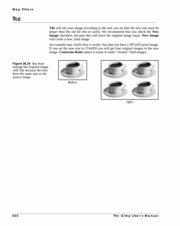
M a p F i l t e r s
ge.ew
TILE
Tile will tile your image according to the size you set(but the new size must belarger than the old for this to work). We recommend that you check theNewImage checkbox, because this will leave the original image intact.New Imagewill create a new, tiled image.
An example may clarify how it works: Say that you have a 287x425 pixel imaIf you set the new size to 574x850 you will get four original images in the nimage.Constrain Ratio makes it easier to make “cleanly” tiled images.
Figure 36.24 You mustenlarge the original imagewith Tile because the tileshave the same size as thesource image
Before
After
5 6 0 T h e G i m p U s e r ’ s M a n u a l


C H A P T E R
37 Miscellaneous FiltersAssorted candy...here are all the filters that don’t fitanywhere else. You can find filters for things likemaking stereographic images here. But mostimportantly, you’ll find the ImageMap filter thattargets web site creators.

M i s c e l l a n e o u s F i l t e r s
that
e
ill
ts
.
DIFF
If you want to see the difference between the original image and the versionyou are working on now, this is the filter to use.Diff is very simple to use. First,you specify thebeforeandafter images. Then, you specify how the differencshould be displayed.
You can also select theOutput Type; either New image, New layer in thepresent image or on the image that you invoked the filter from (but this wdestroy the image).
Diff Methods
• Subtract: Shows the difference value of the pixels that have beenaltered, exactly like the Difference Mode does(not the Subtract Mode).
• Paint unchanged: Paints a mask over pixels that haven’t been altered,so that only the changed parts are visible.
• Paint changed: Paints changed pixels, so that only the unchanged parare displayed.
• Two tone: Paints changed pixels with the background color in thetoolbox and unchanged pixels with the foreground color in the toolbox
Figure 37.1 These imagesclearly show the differencebetween the four Diffmethods.
They also seem to show thatsmoking makes you lookolder....
Original image Manipulated image Paint Changes
Paint Unchanged Subtract Two tone
5 6 4 T h e G i m p U s e r ’ s M a n u a l

C h a p t e r 3 7
nas
o be
dif-
m-
your
priatebletheu can
e
IMAGEMAP
Gimp’s ultimate tool forImagemapcreation. Imagemaps are common items oweb pages. You’ll find them in navigation bars, where you click on different arein the image to navigate with your browser.
The clickable areas in a navigation bar must be defined. This usually has tdone in a separate program likeMapEdit , unless you do it manually. ImageMapintegrates an imagemap editor into Gimp so you will never need to launch aferent program.
HOW TO USE IMAGEMAP
Let’s take a look at an example. This is a title bar for the “Fashion Clothing” copany. The retro-styled navigation bar was created in Gimp with the help ofGfig,Dynamic Text in the Filters| Render menu and some photo stockimages.
THE IMAGEMAP INTERFACE
Flatten (right-click|Layers| Flatten Image ) and save your imagein an appropriate graphic format (JPEG, PNG or GIF). If you save it as a GIFmust revert it to RGB mode before applying the filter. Invoke the filteImageMap will now start.
The four blue buttons to the left are the main creation tools; they definerectangu-lar, circular andpolygonareas. Thearrow is a marker tool. You use it to markareas that you want to move or change. To create an area, press the approbutton and click and drag it around the object you want to define as a clickaarea. If you aren’t satisfied with the shape of an area, you can remodel it witharrow tool. We have created areas around the logo and the retro people, as yosee in Figure 37.3.
To remove a map area, select it and press thedeletebutton (with the red X), andit will go away. To open theArea Settingsdialog, select an area and press thmagic wand button.
Figure 37.2 We will use this image as a clickableimagemap in our web page
T h e G i m p U s e r ’ s M a n u a l 5 6 5

M i s c e l l a n e o u s F i l t e r s
L
uts
likewill
THE AREA SETTINGS DIALOG
LinkWhen you release the mouse after having created a clickable area, theArea Set-tings dialog will appear, displaying a link window where you specify the URthat the defined area should navigate to. In theURL to activate when thisarea is clicked input field you specify the URL of the link, but you can alsoopen a file dialog to specify the file name/URL that should be the link.
If there areframesin your web page you can set the target ID in the target inpfield. (It’s beyond the scope of this book to explain all HTML/web-specific wordand we assume that you are somewhat familiar with web creation.)
You can also write a comment about the area, that will show up in placesNetscape’s status window. We recommend that you use a comment thatinform the user where the link will take them.
Figure 37.3 ImageMap’s main interface
Figure 37.4 The Link tab
5 6 6 T h e G i m p U s e r ’ s M a n u a l

C h a p t e r 3 7
,up ofyours the
from
e
Rectangle, Circle And PolygonIf you want to edit a defined area, you can either use thearrow/selecttool or theArea Settings dialog. Usually, mouse-clicking to define an area will sufficebut sometimes you need better precision. Because a polygon shape is builtseveral nodes, you may want to add or remove nodes. You can’t do that withmouse, so this is where the Rectangle/Circle/Polygon tab comes in. To accesArea Settings window for a selected area, click on themagic wand tool.
JavaScriptIf you want to enable a JavaScript when you drag the mouse over and awaythe area, you can do that in theJavaScript tab. You don’t have to include theonMouseover= “ and the ending” around the JavaScript function call, becausthose characters are added by ImageMap.
Figure 37.5 The different Area Settings tabs
PolygonRectangle Circle
Figure 37.6 The JavaScript dialog
T h e G i m p U s e r ’ s M a n u a l 5 6 7

M i s c e l l a n e o u s F i l t e r s
ate
r,
ofpingdown
n of
THE MAIN WINDOW
The Image WindowThe main window is divided into two sections; theimage window to the left,shown in Figure 37.7, and thearea window to the right, shown in Figure 37.8.
The image window displays your Gimp image, and it is here that you creimagemaps.
In the icon bar above the image window, you cansaveandopen imagemap files,setpreferencesandzoom in and out. If two defined areas overlap each otheyou can choose to send an area to front or to back using thestack control icons.
The Area WindowThe area window displays a list with information of all created areas. Click onethe map areas in the list to select it. To change the specified order of overlapareas, select the line and press the green arrows to move the line either up orin the stack.
The left field below the area window describes the (absolute) current positiothe mouse cursor in the image window. The right field describes thewidth andheightof a dragged rectangular map, theradiusof a circular map and the relativecursor position for polygon maps.
Figure 37.7 The image part of the main window
5 6 8 T h e G i m p U s e r ’ s M a n u a l

C h a p t e r 3 7
ult
To
to
GridA grid can be very helpful when you create definition areas. Click on thegrid iconto add a grid system to the image window. If you aren’t satisfied with the defagrid size or shape, invokeGoodies|Grid Settings to bring up thegriddialog. Here, you can specify the type, proportions and position of the grid.enable the new settings, press OK.
MapinfoWhen you have finished mapping, it’s time to think of what type of imagemapuse. ImageMap supports three kinds of map file formats:
• NSCA is used by the NSCA web server and NSCA-related servers.
• CERN is used by the CERN web server.
• CSIM is used forclient side imagemaps, i.e., imagemaps that arehandled by the web browser instead of the web server.
Figure 37.8 The Area part ofthe main window
Figure 37.9 The Grid dialog
T h e G i m p U s e r ’ s M a n u a l 5 6 9

M i s c e l l a n e o u s F i l t e r s
work
-
our
o
riatedo
file.So,
We recommend that you use CSIM maps because they are so much easier towith. To specify the map type, press theMap Info icon (the paper icon) and theSettings for this Mapfile dialog will appear. At the time of this writing(ImageMap 0.4), only theMap file format option is enabled. To set the mapinfo (type), check the appropriate button and press OK.
CREATION OF THE MAP FILE
You have to save your map file to be able to paste the map information into yHTML document. Save your file with theright-click|File| Save com-mand.
You will now have a map file containing all map information. All you have to dis open the map file in atext editor and open theweb pagethat is going toinclude the imagemap in another text editor. Paste the map info to the appropplace in your HTML code. (There are, of course, several editors and ways tothis, we only describe a generic way.)
Because you can open a map file for re-editing, don’t delete the saved mapThe map file may come in very handy if you want to change your imagemap.remember to always copy/paste your map info into the HTML file.
Your Map Info May Look Like This:
<IMG SRC=”/images/image_map-export.tif” WIDTH=680 HEIGHT=185BORDER=0 USEMAP=”#mapje”>
<MAP NAME=”mapje”>
<AREA SHAPE=”POLY” COORDS=”10,34,136,16,304,91,296,134,4,163,10,34,10,34” ALT=”About Fashion Clothing”TARGET=”main” HREF=”./about.html”>
<AREA SHAPE=”RECT” COORDS=”349,26,408,127” ALT=”Men’sFashion Clothing” TARGET=”main” HREF=”./men.html”>
<AREA SHAPE=”RECT” COORDS=”415,23,464,127” ALT=”Women’sFashion Clothing” TARGET=”main” HREF=”./women.html”>
<AREA SHAPE=”RECT” COORDS=”483,26,547,126” ALT=”FashionClothing for teens” TARGET=”main” HREF=”./teens.html”>
<AREA SHAPE=”RECT” COORDS=”561,47,619,125” ALT=”FashionClothing for kids” TARGET=”main” HREF=”./kids.html”>
<AREA SHAPE=”RECT” COORDS=”0,0,680,185” ALT=”Main page”HREF=”./index.html”>
</MAP>
5 7 0 T h e G i m p U s e r ’ s M a n u a l

C h a p t e r 3 7
The HTML Code May Look Something Like This:
<HTML>
<HEAD>
<TITLE>
Imagemap creation in Gimp
</TITLE>
</HEAD>
<BODY>
<!-- Here the imagemap code begins-->
<IMG SRC=”image_map-export.gif” WIDTH=680 HEIGHT=185BORDER=0 USEMAP=”#mapje”>
<MAP NAME=”mapje”>
<AREA SHAPE=”POLY”COORDS=”10,34,136,16,304,91,296,134,4,163,10,34” ALT=”AboutFashion Clothing” TARGET=”main” HREF=”./about.html”>
<AREA SHAPE=”RECT” COORDS=”349,26,408,127” ALT=”Men’sFashion Clothing” TARGET=”main” HREF=”./men.html”>
<AREA SHAPE=”RECT” COORDS=”415,23,464,127” ALT=”Women’sFashion Clothing” TARGET=”main” HREF=”./women.html”>
<AREA SHAPE=”RECT” COORDS=”483,26,547,126” ALT=”FashionClothing for teens” TARGET=”main” HREF=”./teens.html”>
<AREA SHAPE=”RECT” COORDS=”561,47,619,125” ALT=”FashionClothing for kids” TARGET=”main” HREF=”./kids.html”>
<AREA SHAPE=”RECT” COORDS=”0,0,680,185”ALT=”Main page” HREF=”./index.html”>
</MAP>
<!--And here the imagemap code ends-->
</BODY>
</HTML>
T h e G i m p U s e r ’ s M a n u a l 5 7 1

M i s c e l l a n e o u s F i l t e r s
asok atame
ate
lling
MAGIC EYE
Magic Eye lets you create 3-D stereo images in Gimp. I think everybody hseen 3-D images in magazines: a strange-looking image that you have to loin a certain way, and up pops a flower or something. Now you can do the sthing in Gimp.
EXAMPLE AND PARAMETERS
1. First create agrayscale map image, like the one shown in Figure 37.11. (Thiswill be the image containing the 3-D thing that will pop up.) Remember ththe brighter the object is in the map image, the higher it will pop up in thstereo image.
2. Create amask image, like the one in Figure 37.12. (This is the image that wihide the map image.) The image must have several colors in it if this is goto work properly (a repeated texture is great) .
Figure 37.10 The MagicEye dialog
Figure 37.11 The grayscale map image that will pop out inthe stereogram image
Figure 37.12 The mask image that will build up thestereogram image.
5 7 2 T h e G i m p U s e r ’ s M a n u a l

C h a p t e r 3 7
of
t.
p
eate
).
s ae-
3. Bring upMagic Eye from the map image.
4. Select the mask image in theBackground menu.
5. In theStrip slide bar, set how many columns (a column is one pixel wide)themask image you want to use for the background pattern clone strip(preferably between 50 and 100). The columns are counted from the lef
6. Remember that you must leave the first and last part of themap imageblack(about half the size of the background strip).
7. Depth is the amount of 3-D you want (or how much you want the thing to poup).
8. From left will build your image from the left instead of from the middle ofthe image. (For some reason, a 3-D image is often easier to see if you crit from the left.)
9. Down carves the image instead ofraising it.
10. You have now hopefully chosenDepth, Mask andStrip .
11. PressOK or Create, and the new 3-D image will appear (see Figure 37.13
STEREOGRAM
The Stereogram filter creates a 3-D stereogram of agrayscaleimage (similarto Magic Eye).
If you checkSIS (Single Image Stereogram), the background will be used apattern. InSIRDS (Single Image Random Dot Stereogram), you’ll only get streo noise for background.
Figure 37.13 The final stereogram
Figure 37.14 TheStereogram dialog
T h e G i m p U s e r ’ s M a n u a l 5 7 3
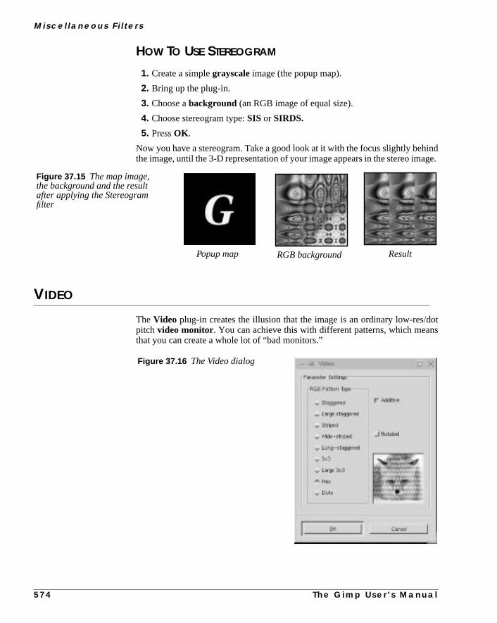
M i s c e l l a n e o u s F i l t e r s
indage.
otns
HOW TO USE STEREOGRAM
1. Create a simplegrayscale image (the popup map).
2. Bring up the plug-in.
3. Choose abackground (an RGB image of equal size).
4. Choose stereogram type:SIS or SIRDS.
5. PressOK .
Now you have a stereogram. Take a good look at it with the focus slightly behthe image, until the 3-D representation of your image appears in the stereo im
VIDEO
TheVideo plug-in creates the illusion that the image is an ordinary low-res/dpitch video monitor. You can achieve this with different patterns, which meathat you can create a whole lot of “bad monitors.”
Figure 37.15 The map image,the background and the resultafter applying the Stereogramfilter
Popup map RGB background Result
Figure 37.16 The Video dialog
5 7 4 T h e G i m p U s e r ’ s M a n u a l
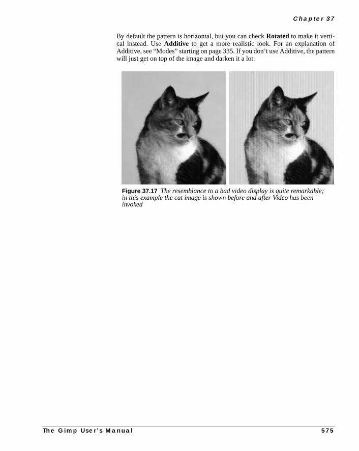
C h a p t e r 3 7
frn
By default the pattern is horizontal, but you can checkRotated to make it verti-cal instead. UseAdditive to get a more realistic look. For an explanation oAdditive, see “Modes” starting on page 335. If you don’t use Additive, the pattewill just get on top of the image and darken it a lot.
Figure 37.17 The resemblance to a bad video display is quite remarkable;in this example the cat image is shown before and after Video has beeninvoked
T h e G i m p U s e r ’ s M a n u a l 5 7 5


C H A P T E R
38 Noise FiltersNoise filters will add noise effects to your image, suchas monitor noise, film graininess or just pointillisticartistry. This is the place to find such a filter.

N o i s e F i l t e r s
rpenke it
n-ise
ouativethe
Youes.
NOISIFY
Noisify adds random noise to the entire image. If you have used a lot of Shato fix an unfocused photo, you can add a little noise to oversharp areas to malook more natural.
Note: This filter will not work with indexed images.
PARAMETERS
You can add noise to all of theRGB channels, or to each RGB channel indepedently. The reference scale goes from 0.00 — no noise — to 1.00 — full nolevel.
• Channel 0 isred (or gray in a grayscale image).
• Channel 1 isgreen (or alpha in a grayscale-alpha image).
• Channel 3 isblue
• Channel 4 isalpha (in an RGB-alpha image).
If the Independentbutton is checked, each channel will get the noise level yhave specified with the sliders. If Independent is unchecked, the same relnoise pattern will be applied to all channels, so that the color balance fromoriginal image is kept intact.
RANDOMIZE, HURL, PICK AND SLUR
These plug-ins causerandom displacement of pixels in three different ways.
OPTIONS
The random displacement can be adjusted to affect 0% to 100% of the pixels.can also specify if you want the filter to be repeated only once, or up to 100 tim
Figure 38.1 Example of ahigh amount of noise in theright part of the image
5 7 8 T h e G i m p U s e r ’ s M a n u a l

C h a p t e r 3 8
tlter.bern-
lue
ent
use
T h e G i m p U s e r ’ s M a n u a l 5 7 9
You can set therandomization seed to generate numbers from the currentime so that there will be a new random operation every time you repeat the fiIf you set a value of your own choice in the input field, a given operation willrepeated each time. All three Randomize filters work for all image types. A waing is in place forHurling , because a too high Randomization or Repeat vawill produce solid noise with no trace of the original image.
RANDOMIZATION TYPES
• Hurling: Changes a pixel to a random color, if it’s within the givenrange of randomization.
• Picking: Applies the highest channel values picked from three randomneighbor pixels to the channels in the chosen pixel.
• Slurring: This is similar to Picking, but this filter will distort yourimage downward. If a pixel is chosen to be slurred, there’s an 80 percchance that a channel value from the pixel directly above it will beapplied; otherwise, a random neighbor above the chosen pixel will beused.
The color variation is usually less in Slurring and Picking than in Hurling becathe channel value replacement often results in shades of gray.
Figure 38.2 Because the Hurl effect is easy tooverdo, you have to lower the values. The image tothe right was Hurled with 20% randomization and1 repeat. Pick and Slur were applied with 50%randomization and 3 repeats. Observe that onlythe right sides of the images have been altered.
Pick
Hurl
Slur

N o i s e F i l t e r s
the
heruselace-
SPREAD
TheSpreadplug-in spreadsthe pixels in your image. It will move a pixel to arandom location. However, this location will be in the range of your setting inslidebars. This makes it possible to spread the imagevertically, horizontallyor inboth directions.
With this filter, the noise effect will not appear in the entire image as with the otnoise filters. You will only see it in the border of contrasting areas. Also, becaonly the colors present in the image will be used, and there is no channel dispment, no new colors will be introduced.
Figure 38.3 Spread wasapplied to the right side ofthe image
5 8 0 T h e G i m p U s e r ’ s M a n u a l


C H A P T E R
39 Render FiltersWould you like to create wonderful lifelike trees, orperhaps make an interesting texture? This is a realtexture factory. You can create the most sophisticatedimages, drawings and textures here.

R e n d e r F i l t e r s
.func-aria-
esll asld
of
CML EXPLORER
Well, I suppose you might callCML Explorer the Swiss army texture makerYou can compose an abstract pattern based on 12 different mathematicaltions, 14 different ways of composing those functions and 10 arrangement vtions. As if that wasn’t enough, you can also set 10 control parameters.
Now, if you think this is a lot...that’s just the choice of settings for the Hue valuof this plug-in. You also have those options for Saturation and Value, as wea variety of additional options. Writing full documentation for this plug-in woube too extensive for this manual, but we’ll give you a few guidelines.
GENERAL SETTINGS
Functions
• The first function type is calledKeep Image’s Value. This means thattheHue, Saturation or Value of the image you opened this plug-infrom will stayunchanged, so if you have chosen this function, there’s nopoint in changing any of the other settings in that tab.
• Keep First Value doesn’t have anything to do with your image — itjust sets the initial colors to standard cyan “shower curtain” with a littlespilloff from the surrounding colors in the HSV color circle (Saturationand Value also get a standard curtain).
• Fill with parameter K , sets a quite smooth surface, which iscontrolled by theK slide bar. The other functions that contain K arevariations of the function, but they create very interesting brocade-likepatterns when you raise the K-value (see the example to the top/rightFigure 39.2), though high values always end up with colored noise.
• Delta creates similar patterns. TheSinusfunction creates wavelike shapes(with the right setting), like northern light or curtain folds, as in Figure39.1.
Figure 39.1 Example of a CML texture
5 8 4 T h e G i m p U s e r ’ s M a n u a l

C h a p t e r 3 9
it to
er,
Composition And ArrangementYou can experiment withComposition/Misc. Arrangement as you like,but the effect varies so much with the other parameters that you can compareForrest Gump’s chocolates: You never know what you’re gonna get....
Still, it is often the case thatComposition functions starting withMax producedenser, darker patterns thanMin functions.
Random Arrangement usually results in striped patterns, andGradientArrangement causes shifts or blends from one side of the pattern to the othso you can’t use a gradient arrangement for tileable patterns.
The Slide BarsThe slide bar settings are equally hard to predict, but this is generally true:
• Moderation Rate goes from vertical stripes to rounder shapes.
• Environment Sensitivity has a similar effect, but breaks up thepattern more.
• Diffusion distance changes the sense of size and direction.
• Number of Subranges increases complexity in the pattern.
• Parameter K andParameter Paffect functions containing thosevalues.
• Low Range and High Range control the Value ranges of each HSVtab.
Figure 39.2 A few moreexamples of CML textures. Themultitude of options in the CMLfilter make it possible to create avery large number of differenttextures. The hard part is tocontrol what texture you’regoing to get.
T h e G i m p U s e r ’ s M a n u a l 5 8 5

R e n d e r F i l t e r s
l-
tternsof a
enn-
e
g-them:billy
ADVANCED SETTINGS
The Advanced settingstab allows you to experiment withChannel sensitivityandMutations for random seed. Use it with care, or you’ll just end up with coored noise.
Other OptionsThis tab lets you set achannel independentinitial value for the pattern youwant to create. Note that this option often locks the pattern in ahorizontal direc-tion. You can alsoZoom or Offset your pattern in this folder.
Miscellaneous OptionsThese options include the possibility tocopy andchangethe settings from onechannel to another. You have probably seen that you can save and load payou have created in CML explorer. Here’s an option to just load the settingscertain channel instead of the whole pattern.
Tip: You’ll often get a better looking pattern by changing it to grayscale, and thback to RGB. After that, you can set any color you like with the Image/Color cotrols.
CHECKERBOARD
TheCheckerboard plug-in createsCheckerboards — what else?
The Sizeslide controls the size of the checkers in pixels (X x Y pixels). If youcheck Psychobilly, you’ll get tiled 3-D “pouting” checkerboards (see Figur39.5). Size now represents the biggest check in a tile.
Say that you setSizeto 4 pixels, then the middle check (which is always the bigest one) will be 4x4, the next check will be one pixel thinner, until you get toouter check which is always one pixel wide. The check size follows this algorith1,2,3,... “check size”...,3,2,1. From this you can determine that each Psychotile will be 16x16 (because 4x4=16).
Figure 39.3 TheCheckerboard dialog
5 8 6 T h e G i m p U s e r ’ s M a n u a l

C h a p t e r 3 9
youre
e.
ate.forass
If, for example, you choose 12 as check size, for an image that is 288x288,will end up with four Psychobilly tiles, because 12x12 gives you tiles that a144x144 pixels big, and there can only be four such tiles in a 288x288 imag
DIFFRACTION PATTERNS
Diffraction Patterns lets you makediffraction or wave interference tex-tures. You can change theFrequency, Contours and Sharp Edgesfor eachof the RGB channels.
You can also setBrightness, Scattering and Polarization of the texture.There is no automatic preview, so you must press the preview button to updThis is a very useful filter if you want to create intricate patterns. It’s perfectmaking psychedelic, batik-like textures, or for imitating patterns in stained gl(as in a church window).
Figure 39.5 PsychobillyCheckerboard mode
Figure 39.4 NormalCheckerboard mode
Figure 39.6 TheDiffraction patterns dialog
T h e G i m p U s e r ’ s M
a n u a l 5 8 7
R e n d e r F i l t e r s
your
it itnge
he
dits.
ble
nd
ner
re-
DYNAMIC TEXT
If you want to add a text string that consists of more than a few characters toimage, we recommend that you use theDynamic Text plug-in. Dynamic Textis much more powerful than Gimp’s ordinary text tool.
When you add text to an image with the Text tool in the toolbox, you can’t edonce you have applied the text to the image. For example, if you want to cha“Hi” to “Hello” you have to erase the old floating text selection and reenter tnew text.
With Dynamic Text, you don’t have to worry about such things. It’s easy to etext; you can change “Hi” to “Hello” without any erasing or reentering operationYou can even write text in a separate text file, import it into Gimp and still be ato edit the text within Gimp. And of course, Dynamic Text hasmulti-line capa-bility. The core Gimp text tool only handles single text lines.
When you first open Dynamic Text, it will create a specialGDyn Text layer; oth-erwise, it will not be able to manage the text processing. Just pressDismissandcarry on.
THE MAIN WINDOW
The mainDynamic Text window will appear, showing a largeText field. Thisis where you type the text that you want to render into Gimp. You will also fiseveral icon buttons and drop-down menus.
Let’s quickly define the names of these options. Starting at the top-left coryou’ll find the following icons:
• Layer
• Load
• Color
• Antialias
• Left
• Center
• Right,
• Preview
• Special Character
Directly above the Text field, there is an alphabeticFont Preview field. Youcan select a font in the drop-down menu, and view the new font in the Font Pview field (and in the Text field if you have written something there).
5 8 8 T h e G i m p U s e r ’ s M a n u a l

C h a p t e r 3 9
e.
rt of
l ine a
on
the
ewext
Style And SizeAbove the Font Preview field, you’ll find drop-down menus for Style and Siz
Style describes the three basic properties of the font variations. The first pathe style string describes theweight or thickness of the characters, such asbold,demior light. The next part, which represents theslant or posture of the charac-ters, is described by a single letter: i foritalics, r for romanand o foroblique. Thethird and last part of the style string describesspacing, such asnormal or con-densed.
Sizecan be measured in eitherpointsor pixels. One point is always 1/72 of aninch (72 points per inch), and one pixel in Dynamic Text represents one pixeyour Gimp image. If you set this option to points instead of pixels, you will sedifference if you’re using a high-resolution monitor.
For more information on fonts, read “How To Get Fonts To Gimp” startingpage 759, and “Text And Fonts” starting on page 165.
The Text FieldType a sentence in the Text field. If the sentence is longer than the width ofwindow, Dynamic Text will display a small curvedarrow in the right side of thewindow. The arrow means that there isno line break.
To create a real line break, pressEnter, as you would in a normal text editor. Ifyou select another font, the text will automatically be updated to show the nfont. However, you can only use one style (font, size, justification, etc.) for tstrings created with Dynamic Text.
Figure 39.7 The main Dynamic Textwindow; note the small arrows thatindicate “non-linebreak”
T h e G i m p U s e r ’ s M a n u a l 5 8 9

R e n d e r F i l t e r s
the
oose
youer
or
ndandery
he
SPECIAL CHARACTERS
If you want to include special characters, such as ©, Ò or †, you have to invokeSpecial Characteroption by clicking on the "Abc" icon. This will bring up awindow containing all characters and symbols present in the selected font. Cha special character or symbol, and press Insert.
Don’t get confused if you don’t see any special characters right away whenopen the dialog. Drag the slider down, and you will find the symbols a bit furthdown in the character list.
OPTIONS
There are several advanced options in the Dynamic Text dialog.
If you are writing an entire text block, you may wish to set thejustification ofthe text. The justification options allow you to set straight margins to the leftright or to align each line break to the center. This is done by enabling theleft,right or center icon.
You can control antialiasing by enabling/disabling theantialiasing icon (the Aicon). Antialiasing is enabled by default in Dynamic Text, and we recommeyou always keep this button checked to prevent the letters from looking jaggyugly. (There is one exception to this rule, and that is when the font size is vsmall.)
You can alsorotate the text by setting another rotation angle other than 0 in tRotation field.
Figure 39.8 The Special characters dialog.Just pick your character and click Insert.Notice that we have scrolled down a bit, inorder to view the characters.
5 9 0 T h e G i m p U s e r ’ s M a n u a l
C h a p t e r 3 9
s-rcanhin-filled
ext.ter.s-
Press
rig-tryse.
ditic
is-ed
owlug-
You can specify thecolor of the rendered text with the Dynamic Text tool. Presing thecolor icon will bring up a color dialog where you can select a color. Afteyou have pressed OK, the color icon will display the new color. Because youonly choose one color for your text, you may want to change the color later witthedynamic text layer. If you change the color in the layer, you can, for example, select a certain word and fill it with red, or you could use a gradient as“color.” Still, keep in mind that any changes made within the layer will be erasthe instant you open Dynamic Text again to re-edit the text.
RE-EDITING DYNAMIC TEXT
What’s so great about Dynamic Text is that it allows you to re-edit rendered tTo change your text, make the dynamic text layer active and invoke the filYour text will now appear in the Text field (notice that this time, there is no mesage about layer creation). Edit the text as usual and/or set new text options.OK and the changed text will appear in the text layer.
If you’d like to keep the old text layer, then enable theLayer icon. With theLayer button checked, the modified text will be placed in a new layer, and the oinal text layer will be preserved. This procedure is very useful if you want toout a variety of different text layouts or designs before deciding which one to u
LOADING TEXT FROM A TEXT FILE
If you want to render large amounts of text into Gimp, it may be convenient to ethe text in a normal text editor, such as Emacs or VI, and import it into DynamText. To import text from a text file, press theLoad button. A file browser willappear where you can specify which file to import. The imported text will be dplayed in the Text field, and you can alter it just as you would text that you typin the Text field.
FIGURES
The Figures plug-in adds a random number ofrectanglesof different size andcolor to your image. You can constrain the average rectangle size toMin /MaxWidth andHeight.
Density controls the number of rectangles. A low density value results in a lnumber of rectangles, and a high value produces a whole lot of them. This pin can also be used as atexture maker.
T h e G i m p U s e r ’ s M a n u a l 5 9 1

R e n d e r F i l t e r s
aria-
et-age/
FLAME
With theFlame filter, you can create stunning, randomly generatedfractal pat-terns. You can’t control the fractals as you can with theIfs Composefilter, butyou can steer the random generator in a certain direction, and choose from vtions of a theme you like.
MAIN INTERFACE
In the main window, you can setRendering andCamera parameters. The firstthree parameters in the Render display areBrightness, Contrast andGamma.The result of these options is visible in the Preview window, but it’s generally bter to stick to the default values, and correct the rendered image later with ImColors.
Figure 39.9 Figures was appliedto the right side of this image
Figure 39.10 Example of Flame
5 9 2 T h e G i m p U s e r ’ s M a n u a l

C h a p t e r 3 9
pre-dandbles
w.
-
the
The other three parameters affect the rendering process and don’t show in theview window. Sample Density, which controls the resolution of the renderepattern, is the most important of these. A high sample density results in softsmooth rendering (like a spider’s web), whereas low density rendering resemspray or particle clouds. TheCamera parameters allow you tozoomandoffsetthe flame pattern, until you’re happy with what you see in the preview windoFlame also offers the possibility tostore andload your favorite patterns.
The Colormap controls the colorblend in the flame pattern. You can set Colormap to:
• The current gradient from theGradient Editor .
• A number ofpreset colormaps.
• The colors from images that are presently open in Gimp. You can useSmooth Palette filter in the Filters/Colors menu to create suitablecolormaps from your images.
Figure 39.11 The Flame dialog
T h e G i m p U s e r ’ s M a n u a l 5 9 3

R e n d e r F i l t e r s
ions
stedy
nine
THE EDIT DIALOG
Pressing theShape Edit button switches to theEdit Dialog.
The Edit dialog shows nine different windows. The pattern displayed in thecenteris the current pattern, and the eight windows surrounding it are random variatof that pattern.
Clicking on the central image creates eight new variations, which can be adjuwith theSpeedcontrol. You select a variation by clicking on it, and it instantlreplaces the image in the middle.
To pick a certain character or theme for the variations, you can choose fromdifferent themes in theVariations menu. You can also useRandomize, whichreplaces the current pattern with a new random pattern.
Figure 39.12 The EditFlame dialog
5 9 4 T h e G i m p U s e r ’ s M a n u a l
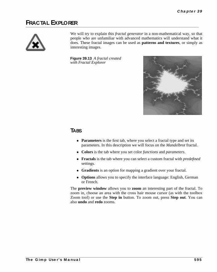
C h a p t e r 3 9
tt it
lbox
FRACTAL EXPLORER
We will try to explain thisfractal generatorin a non-mathematical way, so thapeople who are unfamiliar with advanced mathematics will understand whadoes. These fractal images can be used aspatterns and textures, or simply asinteresting images.
TABS
• Parameters is the first tab, where you select a fractal type and set itsparameters. In this description we will focus on theMandelbrot fractal.
• Colors is the tab where you set colorfunctions andparameters.
• Fractals is the tab where you can select a custom fractal withpredefinedsettings.
• Gradients is an option for mapping a gradient over your fractal.
• Options allows you to specify the interface language: English, Germanor French.
The preview window allows you tozoom an interesting part of the fractal. Tozoom in, choose an area with the cross hair mouse cursor (as with the tooZoom tool) or use theStep in button. To zoom out, pressStep out. You canalsoundo andredo zooms.
Figure 39.13 A fractal createdwith Fractal Explorer
T h e G i m p U s e r ’ s M a n u a l 5 9 5

R e n d e r F i l t e r s
s
senyou
PARAMETERS
XMIN And XMAXXMIN controls how much the fractal will stretch to the left, and XMAX controlthe stretch to the right.
YMIN And YMAXYMIN controls how much the fractal will stretchupward(positive Y values in acoordinate system) and YMAX controls how much it will stretchdownward(neg-ative Y values).
ITERITER stands foriterations,which control the level of detail in the fractal. Manyiterations will calculate more detail, which will take more time. It’s not alwaybest to have a high level of detail. Often a fractal will get more interesting whcreated with lower values. We have found that in the range between 16 and 70will find some very nice fractal patterns.
Figure 39.14 The main view of Fractal Explorer
5 9 6 T h e G i m p U s e r ’ s M a n u a l

C h a p t e r 3 9
es
lues
5/
ory,
he
andffer-
ethatit,
t
CX And CYCX and CY have no impact on Mandelbrot and Sierpinski fractals. CX valubetween -5 and 0 control thehorizontaldistance of the two fractal parts. Low val-ues (-5) take them apart totally, and high values (0) merge them totally. Vabetween 0 and +5 will do the same, but in avertical direction. CY has a similarcontrol mechanism, but not in a horizontal/vertical direction. CY works in a 4225 and 135/315 degree direction.
Load, Reset And SaveThese buttons let you load a specific setting from your personal fractal director save a nice setting that you have made.Resetwill reset the values to the defaultvalues.
Fractal TypeHere, you can choose between well-known fractal types likeMandelbrot, Julia orSierpinsky,but you’ll also find more exotic fractal types likeMan o’ warandSpi-der.
COLORS
A fractal consists ofthreeparts. Anouter part, aninner part and the“fractal”border between them.
Color FunctionThe Sine function controls the color of the inner and outer parts, while tCosine function controls the fractal part.None means that you’ll use linearinstead of trigonometrical mapping for a certain color channel. By checkingunchecking the three color functions you can choose suitable colors for the dient parts of your fractal.
The Inversion button will invert low color values to high color values and vicversa. For example, checking Inversion in the green channel will make areaswere previously low on green full of strong green color. To fully understandtake a quick look at theChannelstab in the Layers & Channels dialog (right-click|Layers| Layers & Channels ). Deselect all channels but thegreen channel, apply theImage|Colors| Invert command, and see whahappens in the image and in the thumbnail channel representation.
T h e G i m p U s e r ’ s M a n u a l 5 9 7

R e n d e r F i l t e r s
ns,
n
use
Color DensityYou can also set theintensityof the color channels with the slides inColor den-sity. This makes it possible to set any color you want to your fractal.
Color ModeEither you use the color mode you have specified with the other Color optiowhich is what you see in the preview window, or you can use agradient from thegradient folder. This option will map the gradient over your fractal. You caachieve quite fantastic-looking fractals this way.
FRACTALS
Here, you’ll find some nice predefined fractals that you can use straight off, oras a backbone or point of departure for your own experiments.
GRADIENTS
Here, you specify the gradient to use in theColors tab. A tip is to bring up thegradient editor so you can take a look at the gradients.
Figure 39.15 The color view of the Fractal Explorer
5 9 8 T h e G i m p U s e r ’ s M a n u a l

C h a p t e r 3 9
tern.ee
sur-ureyed
lick
GENETIC
The Genetic filter generatesrandom textures, much like the KPT TextureExplorer. The generated outcome of these filters is usually a geometrical patIf you want more variation in the random patterns, try the Qbist plug-in; s“Qbist” on page 631.
The original texture is displayed in the middle square, and different variationsround it. If you like one of the alternative textures, click on it. The chosen textnow turns up in the middle, and variations on that specific theme are displaaround it. When you have found the texture you want, click on it and then cOK. The texture will now appear on your drawable.
Figure 39.16 A geometricalpattern created with Genetic
Figure 39.17 The Genetic dialog
T h e G i m p U s e r ’ s M a n u a l 5 9 9

R e n d e r F i l t e r s
cir-zier
eere
a
these
GFIG
This awesome plug-in adds basic drawing capabilities to Gimp. You can drawcles, lines, curves, ellipses, X-sided polygons (X >=3), stars, spirals and Becurves.
The drawing can then berenderedinto your image. The drawing objects havcontrol points that can be moved/edited to adjust the shape of the object. This also aSelectionoption in this plug-in, which transforms a Gfig drawing toselection in your Gimp image, and aSelect+Fill option, which enables you tofill a selection directly from Gfig.
USER INTERFACE
The user interface is divided into aPreview area with adrawing area andusertools, a Settings area withobject manipulationoptions,Grid settings to con-trol grids and a fewtabs to control paintoptions.
PREVIEW AREA
In Opsyou’ll find all the drawing tools. You candraw, delete, move, editandcopyobjects.
LinesTo draw astraight line, simply click on the spot where you want your line tobegin, anddrag andrelease the mouse button where you want it to end.
If you want acrooked line(built of several control points) hold Shift; this willmake the control points attach to each other. For example, hold Shift, click onfirst point, move, click on a second point, move, click on a third point, releaShift, move, and click to get the final point.
Figure 39.18 Gfig is very handy for drawinguncomplicated drawings like this bike, or likethe “F” in Figure 37.2 Naturally, Gfig is notlimited to such simple tasks. In fact you candraw very complex images with Gfig, but thatwas never the purpose of this plug-in.
6 0 0 T h e G i m p U s e r ’ s M a n u a l
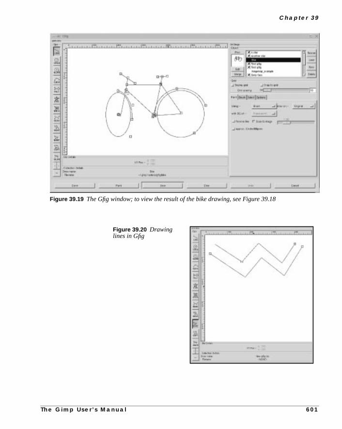
C h a p t e r 3 9
Figure 39.19 The Gfig window; to view the result of the bike drawing, see Figure 39.18
Figure 39.20 Drawinglines in Gfig
T h e G i m p U s e r ’ s M a n u a l 6 0 1

R e n d e r F i l t e r s
d
rve
oint
you
nwant
CircleDraws acircle. The start click becomes the center of the new circle.
EllipseDraws anellipse. The start click becomes the center of the new ellipse.
CurveDraws anarch or asemicircle. The object has three points (two end points ana middle point).
To clear things up, follow this example: Start by drawing a curve where the cupoints are placed in a horizontal row. This will result in astraight line; you cancompare this to a tiny segment of a huge circle. Now, if you raise the middle pa bit, the curve will become a lowarch. It now represents a larger part of theimaginary circle. Finally, reduce the distance between the two end points andwill find that the curve gets even morecircular .
Poly(gon)The default polygon is atriangle, but you can change this by double-clicking othe icon. This brings up a dialog where you can choose how many sides youfor your polygon.
Figure 39.21 Drawingcurves in Gfig
6 0 2 T h e G i m p U s e r ’ s M a n u a l
C h a p t e r 3 9
justith
by
s.
ck-
ricelyAs
justerea to
pe
e ite au
llrol
en
StarThe default star has three spikes, but as with Poly, you can double-click to adthe number of spikes. There are three controls points for further modification wMvPnt .
Thecentral control point allows you to change the relative position of the starrotating it around the outer control point. Theouter control point controls theexternal radius of the star, and themiddle control point controls the size of thecore radius, which determine the relative length and sharpness of the spike
SpiralThis draws a spiral. You can set the number oftwists by double-clicking on thespiral icon. This brings up a dialog where you can also set the direction to clowise or counterclockwise.
BezierThis lets you drawbezier curves. They’re not as easy to modify as the Beziecurves in the toolbox because there are no handles to pull, but it works quite nfor simple drawings. You’ll have to practice a bit to learn how to control them.usual, you end the curve with a Shift+click.
MoveThis moves a single object or all objects in a drawing. To move a single object,click at a control point and drag. To move all objects, hold Shift, click somewhin the drawing area and drag. This will cause all objects in the drawing aremove.
MvPNTMvPNT lets you move a single control point. This function lets you alter the shaof an object bystretching andmoving the lines that it’s made of. As you mayhave noticed, you can’t change the shape of a circle — you can only maksmaller or move it. A way around this problem is to use polygons. If you uspolygon with a lot of sides, you will get something very close to a circle. If yosimply choose theMvPNT tool, you’ll only change it the usual way, but if youhold Shift and then click at a control point with the MvPNT tool active, you’break up the polygon into a lot of lines. Now, you can drag at the “circle” contpoints any way you like.
CopyThis will copy an object. To use it, click and hold an object’s control point, thdrag the copy to where you want it.
T h e G i m p U s e r ’ s M a n u a l 6 0 3

R e n d e r F i l t e r s
-
lue,the
d,
fign
and
addt
DeleteThis deletes an object (the entire object, not just a control point).
Miscellaneous<, > and == let youbrowseyour drawing as if every line of your drawing wasa frame in a movie;< means backward,> means forward and== shows all linesin the drawing.
SETTINGS
ObjectsOne of the nicest things aboutGfig is that you can save a whole bunch of drawings on disk. This makes it possible to createstandard figuresfor your specialneeds.
To create a new drawing, just clickNew and name it in thenaming dialog, andan empty drawing area will appear. The new drawing name is highlighted in band there is a little floppy symbol at the left side of the name, indicating thatdrawing hasn’t been saved yet.
If you want torenameyour drawing, just double-click its name. If you right-clickat a name, you’ll get a menu where you canSave, Save as, Copy andEdit thedrawing.
To edit a drawing, choose the name and either right-click and selectedit or pressthe Edit button. If you got some Gfig drawings from the Internet or from a frienyou can copy them to the gfig directory (~/.gimp/gfig ), pressRe-scanandthey will appear in the name list. If you want to load a drawing outside of your Gdirectory, pressLoad. This brings up an ordinary open file dialog where you cachoose a Gfig drawing. You can browse your drawings by highlighting them,look at them in thePrev window.Deletepops up a dialog asking if you want todelete the drawing (both the file and the name in the browser).
The possibility tomergeGfig drawings is a very nice option. To do so, selectdrawing and pressEdit , then highlight the drawing that you want it to be mergewith, and pressMerge. The selected drawing will now merge with the highlightedrawing. Only the Edit drawing will be altered — the highlighted drawing will nobe changed.
Figure 39.22 The objectpart of Gfig
6 0 4 T h e G i m p U s e r ’ s M a n u a l

C h a p t e r 3 9
t
g atble
anfour
f
Command BarThere’s also a command bar at the bottom of Gfig.Done is for when you want toexit Gfig after you’re finished with it.Paint executes your command, that is, ipaints your Gfig drawing into a Gimp image according to your settings.Savesaves a Gfig drawing.Clear will erase everything in the drawing area.Undo willundo your last operation.Cancel lets you exit Gfig, and drop all that you havedone.
GridGrid controls the support grids in the Gfig drawing. If you have selectedGridType: Rectangle in the Options tab, you can set thegrid size in X*X pixelswith the Grid spacing slide. You can also choose toDisplaythe grid, and to makeyour objectsSnap tothe grid.Snap to grid is an excellent tool if you work withprecision drawings. If you move objects with Snap, the anchor point you drawill snap to the grid. If you move all your objects with Snap enabled, an invisimiddle point will be calculated and that point will snap to the grid system.
THE TABS
PaintTheUsing menu controls where paint is, or can be, applied. UseBrush to paintthe outline of the drawing,Selectionif you want to transform the drawing to aselection orSelection+Fill if you want to make a selection and then fill it witha color or pattern (see “Select” on page 608).
Draw on determines where the drawing is placed.Original puts the drawing onthe original image,newcreates a new layer for the drawing andMultiple createsa new layer for each object in your drawing. If you select New or Multiple, you calso set what type of background you want for the new layer. There areoptions:Transparent, Background (fills with the current background color inthe toolbox),White andCopy (copies the original image to the new layer). Iyou choose Multiple, the previous layer will be copied to the new layer.
Figure 39.23 The Paint tab
T h e G i m p U s e r ’ s M a n u a l 6 0 5

R e n d e r F i l t e r s
ni-
s.trillithise
Example:
• Input imagejulius.tif and a Gfig drawing with three objects.Drawon Multiple with Bg Transparent. This setting results in:
• Background: Julius
• Layer 0: The first draw object
• Layer 1: The second draw object
• Layer 2: The third draw object.
• Input imagejulius.tif and a Gfig drawing with three objects.Drawon Multiple with Bg Copy. This setting results in:
• Background: Julius
• Layer 0: Julius plus object 1
• Layer 1: Julius plus objects 1 and 2
• Layer 2: Julius plus objects 1, 2 and 3.
This obviously fits like a glove when you want to make GIF animations (see “Amation Filters” starting on page 369).
With the Reverse lineoption, you can control the direction of brush strokeNormally, therenderingof your stroke goes from the first control point to the lasone. If you setbrush fade out to 20 in the Brush tab, the stroke will fade out afte20 pixels (counted from the first control point). If you check Reverse line it wfade out from the last control point instead of the first. This option works wlines, curves and polygons. When it come to polygons, fading goes clockwfrom the first control point if Reverse line is unchecked.
Figure 39.24 The difference between havingReverse line unchecked and checked. If youcheck Approx Circles/Ellipse, fading will alsoapply to circles and ellipses.
Reverse line unchecked Reverse line checked
Figure 39.25 Linein Gfig, which starts at10,15 and ends at220,220
6 0 6 T h e G i m p U s e r ’ s M a n u a l

C h a p t e r 3 9
5
er
Gfigt it,
ade
If you check Approx. Circles/Ellipse, fading also applies to circles andellipses. The fading goes clockwise from thefirst control point. For example, ifyour first control point is at 5 o’clock, then the non-faded part will start ato’clock and continue to fade so that your line fades out at 10 o’clock.
UsingScale to image, the drawings can be set to fit the image, or just get biggor smaller. Just uncheck and drag the slider toscale up/down. This is a nice optionthat makes it easy tomagnify your drawings and work with small details. Whenyou’re done, check Scale to image tozoom out.
BrushIn this tab you choose a suitablepaint brush. A tip is to bring up theSelectbrush dialog so you can set the spacing and opacity of the brush; otherwise,will use the default values of the brush you select. To select a brush, highlighand it will be displayed in the preview.
You can choose from four different types of brushes.Brush is an ordinary brush,with a Fade Out control that controls where the stroke will start to fade out (If FOut is set to 0.0, there will be no fading).Airbrush is like a spray can with pres-sure control,Pencil is like a brush with hard edges, andPattern allows you topaint with a pattern (much like the Clone tool does).
Figure 39.26 The Brushtab, notice that fading isdisabled if Fade Out is set to0.0
T h e G i m p U s e r ’ s M a n u a l 6 0 7

R e n d e r F i l t e r s
rasp
lected
ctould
The
u
is
ear
SelectThis folder is only enabled when painting withSelector Select+Fill. In orderto understand the different Selection types, you have to have a fairly good gof basic selection (see “Selection Tools” starting on page 109).
An ExampleSuppose that you have made two (overlapping) star objects, and you have sePaint with Select in the Paint folder. If you now chooseAdd as Selectiontype, you’ll get a selection that is acombinationof the two objects (a merged dou-ble star).
If you chooseSub, you’ll get nothing (because there is no selection to subtrafrom), but if there had been a previous selection, the shape of the twin stars wbecut from this selection. If you chooseReplace, the previous selection will bereplacedwith the star that you painted last in the drawing area.Intersect meansthat the intersection of the two star objects will become a selection.
You can fill the selection with apattern, foreground or background color(Fill Opacity controls the transparency of the fill). You must bring up thePatterndialog to set a pattern; otherwise, the last or default pattern will be used.Fill after button controls the fill order; e.g., if you chooseAll selections andReplaceas the selection type, only the last drawing object will be filled. If yohad chosenEach selection, then all objects would get filled.
Feather controls the gradual transparency or edge softness of the selection.Arcasdetermines how curved objects will be treated. If you set this parameter toSec-tor , curves will be treated as circle sectors (pie slices), and if you set it toSeg-ment, they are filled as circle segments (half-moons). The last optionAntialiasing, which is generally good to enable.
OptionsThis folder contains various options, like the possibility to make an image appin the preview drawing area, or toreload it after applying a drawing. You canalsohide the center points in drawing objects, gettool tips, set a different levelof undo, or change the color and shape of thegrid system. You can also chooseto show the X/Y position of the mouse in theObj Details window. If you wantto achieve a high level of precision, this option is very useful.
Figure 39.27 The Selecttab
6 0 8 T h e G i m p U s e r ’ s M a n u a l

C h a p t e r 3 9
ow
EXAMPLE
In order to understand this nice plug-in, we will give you a simple example: Hto make a star with sparkles around it and a gradient fill.
1. Bring up a new (black) image, invoke Gfig and chooseNew Object.
2. Choose thestar object, set it to seven spikes and draw it.
Figure 39.28 The Options
Figure 39.29 Click Newin the Object part of Gfig
Figure 39.30 Double-click on theStar symbol in the Gfig drawing area
Figure 39.31 Draw the star
T h e G i m p U s e r ’ s M
a n u a l 6 0 9
R e n d e r F i l t e r s
a
3. ChoosePaint with Brush and a Brush/Small Galaxy brush.
4. PressPaint to paint the sparkling outline of your star.
5. Now switch toPaint with Selection.
6. PressPaint, which will produce a star-shapedselection.
7. Now, bring up theGradient Editor and choose Cold_Steel as a gradient.
8. Double-click on theBlend tool (in the toolbox) and set Blend to Custom andGradient to Conical (asymmetric) in the dialog.
9. Set the Blend tool in the center of the star and blend. You will now havefrosty star.
10. We have added a little extra glamour to the star by applying theright-click|Filters|Light Effects| Sparkle plug-in.
Figure 39.32 Clickon the Brush tab toselect the Galaxy brush
Figure 39.33 The paintedoutline of the star
6 1 0 T h e G i m p U s e r ’ s M a n u a l

C h a p t e r 3 9
on-
G
ap
GRID
With theGrid filter you can easily create a grid system. The Size parameter ctrols the size and proportions of the grid squares, measured in pixels.Offset con-trols where (in pixels) the first unbroken square will be drawn.
HFGHFG createsheight fields just like in a map, except that a map is real and HFgenerates its height fields randomly.
HFG can produce very interesting results if it’s used together with the BumpMfilter. If you use an HFG, generated image as a map with theright-click|
Figure 39.34 The final frosty star Figure 39.35 The star will lookmore frosty if you add someSparkle to it
Figure 39.36 TheGrid filter is bothuseful and versatile.
Grid used tomake stripes
Grid as base in a curvediagram
Simple Grid
T h e G i m p U s e r ’ s M
a n u a l 6 1 1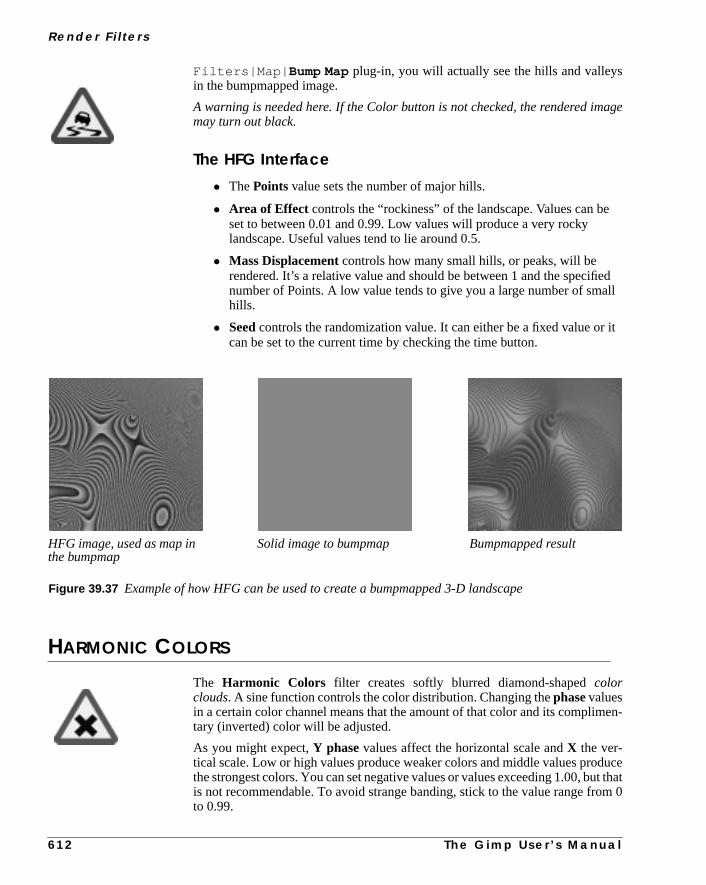
R e n d e r F i l t e r s
age
edall
r it
en-
ucet thatm 0
Filters|Map| Bump Mapplug-in, you will actually see the hills and valleysin the bumpmapped image.
A warning is needed here. If the Color button is not checked, the rendered immay turn out black.
The HFG Interface
• ThePoints value sets the number of major hills.
• Area of Effect controls the “rockiness” of the landscape. Values can beset to between 0.01 and 0.99. Low values will produce a very rockylandscape. Useful values tend to lie around 0.5.
• Mass Displacement controls how many small hills, or peaks, will berendered. It’s a relative value and should be between 1 and the specifinumber of Points. A low value tends to give you a large number of smhills.
• Seed controls the randomization value. It can either be a fixed value ocan be set to the current time by checking the time button.
HARMONIC COLORS
The Harmonic Colors filter creates softly blurred diamond-shapedcolorclouds. A sine function controls the color distribution. Changing thephasevaluesin a certain color channel means that the amount of that color and its complimtary (inverted) color will be adjusted.
As you might expect,Y phasevalues affect the horizontal scale andX the ver-tical scale. Low or high values produce weaker colors and middle values prodthe strongest colors. You can set negative values or values exceeding 1.00, buis not recommendable. To avoid strange banding, stick to the value range froto 0.99.
HFG image, used as map inthe bumpmap
Bumpmapped resultSolid image to bumpmap
Figure 39.37 Example of how HFG can be used to create a bumpmapped 3-D landscape
6 1 2 T h e G i m p U s e r ’ s M a n u a l

C h a p t e r 3 9
ues, or
melyyouore
IFS COMPOSE
This fractal -based plug-in is truly wonderful! With this versatile instrument, yocan create amazingly naturalistic organic shapes, like leaves, flowers, brancheven whole trees.
HOW TO USE IFS COMPOSE
The key to using this plug-in lies in making verysmallandprecisemovements infractal space. The outcome is always hard to predict, and you have to be extregentle when you change the pattern. If you make a fractal triangle too big, or ifmove it too far (even ever so slightly), the preview screen will black out, or mcommonly, you’ll get stuck with a big shapeless particle cloud.
Figure 39.38 Exampleof Harmonic Colors
Figure 39.39 Landscape,flowers, trees...it was all createdin IFS Compose.
T h e G i m p U s e r ’ s M a n u a l 6 1 3

R e n d e r F i l t e r s
keloseatetternhad
e-
e but-
A word of advice: When you have found a pattern you want to work with, maonly small changes, and stick to variations of that pattern. It’s all too easy toa good thing. Contrary to what you might believe, it’s really much easier to crea leaf or a tree with IFS Compose than to make a defined geometrical pa(where you actually know what you’re doing, and end up with the pattern youin mind).
The Main InterfaceThe plug-in interface consists of thecompose areato the left, apreview screento the right, and some tabs and option buttons at the bottom of the dialog.
TheDefaultsetting (in the preview window) is three equilateral triangles. To crate a new pattern, youMove, Rotate/Scaleand Stretch these triangles. Youeither use the three buttons under the compose area, or press the right mouston to access a popup menu.
Figure 39.40 The main IFS Compose dialog
6 1 4 T h e G i m p U s e r ’ s M a n u a l

C h a p t e r 3 9
ou
.e.,Youfrac-sents
e
EXAMPLE
This is a rather complex plug-in, so to help you understand it, we’ll guide ythrough an example where you’ll create a leaf or branch.
Many forms of life, and especially plants, are built like mathematical fractals, ia shape that reproduces or repeats itself indefinitely into the smallest detail.can easily reproduce the shape of a leaf or a branch by using four (or more)tals. Three fractals make up the tip and sides of the leaf, and the fourth reprethe stem.
1. Before invoking the filter: SelectFile| New Image. Add a transparent layerwith Layers|Layers & Channels| New Layer . Set the foregroundcolor in the toolbox to green, and set the background to white.
2. Open IFS Compose. Start byrotating the right and bottom triangles, so thatthey pointupward. You’ll now be able to see the outline of what’s going to bthetip andsides of the leaf.
Figure 39.41 Leaf created withIFS Compose
Figure 39.42 The first stage of our leaf
T h e G i m p U s e r ’ s M a n u a l 6 1 5

R e n d e r F i l t e r s
f
useto
ilose
3. To make the leaf symmetrical, adjust thebottom triangle to point slightly tothe left, and theright triangle to point slightly to the right.
4. PressNew to adda fractal to the composition. This is going to be the stem othe leaf, so we need to make it long and thin. PressStretch, anddrag tostretch the new triangle. Don’t be alarmed if this messes up the image, justScaleto adjust the size of the overlong triangle. You’ll probably also havemove and rotate the new fractal to make it look convincing.
5. You still have to make it look more leaf-like. Increase thesize of the toptriangle, until you think it’s thick and leafy enough. Adjust all fractals untyou’re happy with the shape. Right-click to get the popup menu, and choSelect all. Now all fractals are selected, and you can scale and rotate theentire leaf.
Figure 39.43 The second stage of our leaf
Figure 39.44 The third stage of our leaf
6 1 6 T h e G i m p U s e r ’ s M a n u a l

C h a p t e r 3 9
r
ldnstem
ittle
ingon
.
6. The final step is to adjustcolor. Click on theColor Transformation tab,and choose a different color for each fractal. To do this, checkSimple andpress theright color square. A color circle appears, where you can click oselect to choose a color.
7. PressOK to apply the image, and voilà, you’ve just made a perfect fractaleaf! Now, when you’ve got the hang of it, you’ll just have to experiment anmake your own designs. All plant-imitating fractals (be they oak trees, feror straws) are more or less made in this fashion, which is leaves around a s(or several stems). You just have to twist another way, stretch and turn a lor add a few more fractals to get a totally different plant.
MAIN OPTIONS
• Relative Probability: Determines influence or total impact of acertain fractal.
• Spatial Transformation: Gives you information on the active fractal,and allows you to type a value instead of changing it manually. Changparameters with the mouse isn’t very accurate, so this is a useful optiwhen you need to be exact.
• Simple color transformation: Changes the current fractal color(which is the foreground color in the toolbox) to a color of your choice
Figure 39.45 Final stage, adding the right
Figure 39.46 We have just createdthis delicate fern leaf with amazingdetail, just by a few simple operations inthe IFS Compose filter
T h e G i m p U s e r ’ s M a n u a l 6 1 7

R e n d e r F i l t e r s
l,tal
r
ay,
ot
of
to
• Scale Hue/Value: When you have many fractals with different colors,the colorsbleedinto each other. So even if you set “pure red” for a fractait might actually be quite blue in some places, while another “red” fracmight have a lot of yellow in it. Scale Hue/Value changes the colorstrength of the active fractal, or how influential that fractal’s colorshould be.
• Full color transformation: Changes color influence from the other(inactive) fractals. You can, for example, in the red fractal, set Full colotransformation to red in all of the swatches, and you won’t get anyinfluence at all in that part of the fractal composition.
RENDER OPTIONS
• Spot Radius: Determines the density of the “brushstrokes” in therendered image. A low spot radius is good for thin particle clouds or sprwhile a high spot radius produces thick, solid color strokes much likewatercolor painting (see Figure 39.47 at the bottom right). Be careful nto use too much spot radius — it takes a lot of time to render.
• Subdivide: Controls the level of detail.
• Iterations: Determines how many times the fractal will repeat itself. (Ahigh value for Subdivide and Iterations is for obvious reasons a wasteprocess time unless your image is very large.)
• Max. Memory: Enables you to speed up rendering time. This isespecially useful when working with a large spot radius; just rememberuse even multiples of the default value: 4,096, 8,192, 16,384....
Figure 39.47 There is no end to whatyou can create withIFS Compose and alittle imagination
6 1 8 T h e G i m p U s e r ’ s M a n u a l

C h a p t e r 3 9
nd
s &
ain
e
es.
ill
en
og,
JIGSAW
TheJigsaw filter will create a jigsaw puzzle of your image. Jigsaw puzzles apuzzle pieces can be nice gadgets for web pages.
EXAMPLE
In the following example we will make a half-finished jigsaw puzzle.
1. Start by opening an image that will make a nice puzzle. Open the LayerChannel dialog (right-click|Layers| Layers & Channels )andduplicate the background layer. Name this layerPuzzle.
2. Bucket Fill the original image layer (Background) with an appropriatebackground color (we used a plain white background).
3. Make thePuzzlelayer active. Apply the Jigsaw filter and pressOK (we willexplain the parameters later on).
4. Create anew layer with a white fill type (the width and height must be thesame as in the background layer). Name this layerWhite Puzzleand make surethat it is the top layer. Select this layer and run the Jigsaw filter once agwith the same values (right-click|Filters| Repeat Last ).
5. Apply right-click|Image|Colors| Brightness-Contrast to theWhite Puzzlelayer. Adjust the contrast to the highestvalue and pressOK. You will now have a white puzzle without highlights andshadows.
6. In theWhite Puzzle layer, select the pieces that should be missing from thpuzzle with theFuzzy Selection tool. Select the first piece, then hold downCtrl and select the next piece, and so on, until you have selected all piec
7. Select thePuzzlelayer and toggle off the eye icon from theWhite Puzzlelayer.
8. Move the selection (still with the Fuzzy selection tool enabled) and you wget afloating selection. Double-click on the Floating Selection bar in theLayers & Channels dialog, and name the layerMissing Pieces.
9. Select thePuzzle layer and runright-click|Script-Fu|Shadow|Drop Shadow . Use the following parameter values in the Drop Shadowdialog:Xoffset = 4, Y offset = 4, Blur Radius = 10, Color = Black,Opacity = 80 and checkAllow Resizing. You will now see a shadowunder your puzzle.
10. Select theMissing Pieces layer. Select a puzzle piece with theBezier tool.Carefully adjust the Bezier curve so that you’ll only select one piece. Whyou have turned the Bezier curve into a selection, runright-click|Select| Float .
11. Double-click on the Floating selection bar in the Layers & Channels dialand name the layerSingle Piece. Now, you can move your piece to anappropriate place and maybe rotate it a bit. Run theDrop Shadow script onthis piece, and use the same values as before.
T h e G i m p U s e r ’ s M a n u a l 6 1 9

R e n d e r F i l t e r s
nd
ess”
e,he
findend
12. Toggle on the eye icon for all layers except theWhite Puzzle layer and theMissing Pieces layer, and you will have a nice jigsaw puzzle image.
PARAMETER SETTINGS
The Jigsaw filter has a few parameters.
• TheNumber of Tiles sliders control the number of tiles renderedvertically and horizontally.
• TheBevel width slider controls the slope of the edges of the puzzlepieces (a hard wooden puzzle would require a low Bevel width value, aa soft cardboard puzzle would require a higher value).
• TheHighlight slider controls the strength of the highlight that willappear on the edges of each piece. You may compare it to the “glossinof the material the puzzle is made of. Highlight width is relative to theBevel width. As a rule of thumb, the more pieces you add to the puzzlthe lower Bevel and Highlight values you should use, and vice versa. Tdefault values are suitable for a 500x500 pixel image.
• TheJigsaw Style radio buttons control the shape of the puzzle pieces.We usedCurved pieces for the example image.
L-SYSTEMS
Lindenmayer Systems, called L-Systems, is a mathematical formalismdesigned primarily for concise description of natural shapes of plants. You canout more about the history of L-Systems in the publications mentioned at theof this description.
Figure 39.48 Thefinal result of ourJigsaw example
6 2 0 T h e G i m p U s e r ’ s M a n u a l

C h a p t e r 3 9
ting
ven
If ared
The whole concept of L-Systems consists of two main parts:
• Preparing the L-Systems description.
• Applying this formula to render a graphic representation.
During the preparation stage, the program iteratively applies a set of rewrirules onto a string. The process starts with an initial string (calledaxiom) and forevery iteration this string grows longer. The preparation is finished when the ginumber of iterations have been completed.
A SIMPLE EXAMPLE
To clarify this description, let’s take a look at a simple example:
Axiom = A
Rules = A -> BA and
B -> A
What does it mean?
It means that we start with astring of length 1 that contains the letterA. Foreach iteration, we replace everyA with a stringBA and everyB with string A.This is how it goes:
Iteration 0 AIteration 1 BAIteration 2 ABAIteration 3 BAABAIteration 4 ABABAABA
Note that we can use many different letters in both the axiom and the rules.string should contain a letter for which no rule has been defined, it will be ignoand passed to the resulting string. For example:
Axiom = A
Rules = A -> BA
B -> AC
Figure 39.49 L-Systems
T h e G i m p U s e r ’ s M a n u a l 6 2 1

R e n d e r F i l t e r s
com-ms.
d
p-
Anyree
a
e of
:
t),
Iteration 0 A
Iteration 1 BA
Iteration 2 ACBA
Iteration 3 BACACBA
As you can see, by using a small and concise description we can obtain quiteplex and long character strings. This is the first important lesson about L-SysteYou need only define theseedandrules that govern growth to generate large ancomplicated, yet interesting, data.
GRAPHIC REPRESENTATION
To convert the string generated during thefirst phaseof the process into itsgraphical representation, we must come to an agreement on some assumtions. You can compare therendering process to an imaginaryturtle that drawsa line while wandering over our image. What the turtle does is to “eat” consecutivecharacters, and then it decides what to do next based on that information.character that has no meaning for the turtle is simply ignored. The following thcharacters havefixed meanings:
• TheF character meansgo forward one step, drawing a line.
• Thef character meansjump forward one step.
• The( and) characters will cause our turtle to save its state (position,heading, parameters of its drawing tool), decrease the step length by given factor and to draw a subsystem until it encounters a matchingclosing brace.
• Traditionally, the characters+ and- mean turn left and turn right, but inthis plug-in they are defined as so-calledspecial rules. Users areencouraged to keep the original meaning of these two signs for the sakreadability.
As an illustration for the render process, walk through the following example
String to be rendered: F+fFf+AFAF . Let’s assume that the initial positionof the turtle is (0,0), initial heading is 0 degrees (the turtle is “looking” to the righstep length is 1 and the turn angle associated with the+ and- characters is equalto 90 degrees.
6 2 2 T h e G i m p U s e r ’ s M a n u a l

C h a p t e r 3 9
ngribe
tion;
g by
It’s when you combine the possibilities offered by a concise description of lostrings, by rewriting the rules with a drawing turtle that lets the characters descits way, that you get a really powerful tool.
This idea is called L-Systems.
Take a look at the final example before we move on to some implementadetails. This isKoch’s curve. Below, you have its definition as an L-Systemfirst three iterations, and a picture drawn on the basis of the third string.
Axiom = F
Rules = F -> F-F++F-F
Iteration 0 F
Iteration 1 F-F++F-F
Iteration 2 F-F++F-F-F-F++F-F++F-F++F-F-F-F++F-F
...
As you can tell from the picture, the angle added to the current turtle headin+ and- characters equals 60 degrees.
Interpretedcharacter
Position(x,y)
Heading Result
0,0 0
F 1,0 0 a line from (0,0) to (1,1)
+ 1,0 90
f 1,1 90
F 1,2 90 a line from (1,1) to (1,2)
f 1,3 90
+ 1,3 180
A 1,3 180 (character ignored)
F 0,3 180 a line from (1,3) to (0,3)
A 0,3 180 (character ignored)
F -1,3 180 a line from (0,3) to (1,3)
Figure 39.50 L-System
T h e G i m p U s e r ’ s M a n u a l 6 2 3

R e n d e r F i l t e r s
ue
o
s
eas
toft.
f
ot to
heycom-es to
USING THE L-SYSTEMS PLUG-IN
What can you do with the L-Systems Plug-in?
• You can create a new L-System and give it a unique name and a uniqfile name in which the definition will be stored. You can also use anexisting L-System as a base of a newly defined one, but be sure not tforget to change the file name or you will lose either the new or the oldone! All this is done within the top-left part of the plug-in’s GUI. There isa list with all defined L-Systems and a set of buttons to perform variouoperations on them.
• You can define your L-System by entering anaxiom, a set ofrules andthe number ofiterations that should be performed before rendering. Usthe first page of the notebook at the bottom of the GUI. Adding rules issimple as pressing theAdd button and filling in the pop-up dialogwindow. The same goes for editing and removing rules.
• You can define a set of additional rules applied once only after the lasiteration. You’ll learn more about such rules later. To manipulate the setlast rules you should switch to the second page of the notebook widge
• Once you’ve defined the L-System, you have to move on to thethird pageof the notebook at the bottom of the GUI, and specify the correctinformation about at least twospecial symbols: + and-. This is becausethe special rules for these characters are always included in the set ospecial rules. The only thing you will probably have to do is to providecorrect information about the turn angles.
• Here I should explain something. What does thesemagic special rulesentries mean? That’s quite simple, the rule:
+ -> 60.00: <<CURRENT>>: -1: -1%:(NO CHANGE)
means exactly the following: Theplus character will cause the turtle toincrease its heading angle by 60 degrees, to keep the current brush, nchange brush spacing (the first-1), not to change the opacity (the second-1) and not to change the drawing color.
• In the end you can change various rendering parameters like initialposition andheading, step length, turn andstep randomness andothers.
ADVANCED FEATURES
Using BracesAs I explained before, you can introducematched bracesin both theaxiomand in allrules. They are significant during the rendering process because tcause the turtle to draw part of the L-System in a separate context. The mostmon use of braced L-Systems is to draw plant-like shapes. You use brac
6 2 4 T h e G i m p U s e r ’ s M a n u a l

C h a p t e r 3 9
eon-
tart
pur-ning)ntsaveboland
lookoftheoint.
ake
ust, the
r L-
g
n
denote that after the turtle drawsa branch, it should return to the position wherethe branch started and continue drawing themain trunk. You can changebrushshapes, colors, spacing and so on while drawing the branch, but all of theschanges will have no effect on the visualization of the trunk and, possibly, the csecutive branches.
As an example, look carefully at the definition of L-Systems with names that swith “Plant/”.
The Purpose Of Last RulesAn additional set of rules applied once, just before rendering, serves severalposes. First, it can be used to translate abstract objects (with no turtle meaused in main rules into something visible. You often do this when designing plaor flowers. In this case, every character in main rules and the axiom would ha specific meaning, like root, trunk, leaf and so on. Every such abstract symshould be transformed into something visible with a given color, brush shapelength.
Secondly, you can use last rules to modify the generated shape to make itmore interesting. This is quite common when the L-System looks like a kindgrid. It would be more interesting if you could see the way the turtle has drawnshape but that’s impossible because many lines are connected in a single p
To avoid that, one should define a set of three simple last rules, which will mturns less sharp:
+ -> +F+
- -> -F-
F -> FF
Be sure to adjust the definition of + and - in the special rules section. They muse half the angle they had before the introduction of the last rules. Probablylength of a single step will also have to be cut in half.
Effective Use Of Special RulesLast rules are not only turns! You can use them quite extensively to make youSystems look more lively and realistic.
• First comesbrushes, which will provide you with various textures andline styles.
• Second iscolor. The purpose of using color in the image you are paintinis something you probably know better than me!
• Third isopacity. It works great in plants, where, for example leaves cabe made somewhat translucent to make the picture more interesting.Painting with a semi-opaque paint can also produce nice effects when
T h e G i m p U s e r ’ s M a n u a l 6 2 5

R e n d e r F i l t e r s
ofted
e
rti-
s in
ld
t
the
drawing patterns with intersecting lines. The final color of various partsthe image will then depend on how many times the pixel has been pain— and with what color!
• Fourth and last isspacing, which probably has only one use: to make thprogram draw just a singleprint of a brush instead of an awfulline paintedwith a brush that was not designed for it.
Where To Look For More InformationIf you are interested in the concept of L-Systems look for the following books/acles. For more references, look in Prusinkiewicz’s book.
• P. Prusinkiewicz, J. Hanan Lindenmayer Systems, Fractals and Plantseries“Lecture Notes in Biomathematics,” Springer Verlag, 1989.
• A. R. Smith”Plants, Fractals and Formal Languages”in ACM ComputerGraphics, vol. 18, no 3, July 1984.
MAZE
TheMaze filter will generate amaze. If you want to use it in a pattern, you canmake the mazetileable by checking theTileable? checkbutton.
The Width and Height sliders control how many pathways the maze shouhave. Thelower the values for width and height, themorepaths you will get. Thesame happens if youincreasethe number of pieces in the Width and HeighPiecesfields.
You can specify randomSeedor use the currentTime as randomizer. Using ran-dom seed means that the maze pattern will be different each time you invokefilter.
Figure 39.51 Examples of L-Systems creations. As you can see,they are quite a bit like the IFSCompose outputs. The maindifference, from a user perspective,is that you can save L-Systemsfigures. On the other hand L-Systems are much more abstract,and it is much harder to create andcontrol the organic shapes.
6 2 6 T h e G i m p U s e r ’ s M a n u a l

C h a p t e r 3 9
ther of
ight
ins,have
NCPNCP generates random cloud formations. The rendered image istileable, so youcan use it as a seamlesspattern.
The amount of major clouds is controlled by thePoint parameter. A high valuewill produce more major clouds. The number of minor clouds is controlled byfoo-point parameter. This is a value between 1 and the specified numbemajor clouds.
You can control the randomization with theSeedvalue or checkTime to use thecurrent time as a randomization value. If you are interested in biology, you mlike to run right-click|Image|Colors| Autostretch Con-trast on the generated image. The outcome may look like molecule chaintestinal organs, neural fibers or skin tissue, depending on the values youspecified. Also try right-click|Image|Colors| Adaptive Con-trast , which will produce a more chemical or crystalline effect.
Figure 39.52 The Maze
dialog
Figure 39.54 NCP example
T h e G i m p U s e r ’ s M
a n u a l 6 2 7
R e n d e r F i l t e r s
ralcan
rface
sula-
lot
agehou-the
cialsothe
and
PLASMA
Plasma generates colorfulclouds, which can be used fortextures. However,the rendered plasma image is not tileable like the NCP filter.
You control the turbulence in the plasma cloud with theTurbulence slide. Highvalues give a hard feeling to the cloud (like an abstract oil painting or minegrains), low values produce a softer cloud (like steam, mist or smoke). Youalso generateSeed for random variations in the plasma cloud.
Sometimes the strong colors may be distracting, and a more interesting suwill appear when you desaturate the image usingright-click|Image|Colors| Desaturate .
PHOTO MOSAIC
Photo Mosaic creates amosaic of a target image, where the mosaic stoneconsists of a lot of small source images. This is not an unknown image maniption technique. Last time I saw it was in the poster for the filmThe Truman Showwith Jim Carrey. The poster cleverly built-up a portrait of Jim Carrey from of aof small pictures of TV-sets showing the actor in different situations.
IMAGE LIBRARIES
To make this filter produce a realistic photo mosaic, you’ll need a huge imlibrary. We are not talking about several hundred images. We mean several tsand images! Our image library comprises around 7,000 images. Luckily,images don’t have to be big.
Photo Mosaic doesn’t use the CD-ROM image library as it is. It creates a spePhoto Mosaiclibrary containing downscaled images of the real image librarythe actual image library will be smaller. What you have to remember aboutsource images for the Photo Mosaic image library is that they must be ofequalsize. The exact size is not important, but they should all have the same heightwidth.
When you invoke this filter, start by pressing theHelp button. There you will findall the information that you need to create a Photo Mosaic image.
Figure 39.55 Example of Plasma
6 2 8 T h e G i m p U s e r ’ s M a n u a l

C h a p t e r 3 9
urceis-
The Photo Mosaic image in Figure 39.56 was created from 1,000 tiles, or soimages. Notice that to view the portrait in the image, you must look at it from a dtance.
Figure 39.56 You must view thePhoto Mosaic from a distance in orderto get the picture
T h e G i m p U s e r ’ s M a n u a l 6 2 9

R e n d e r F i l t e r s
234rgetsee
e oratot
rintoon--
IMAGE SIZE
When we created this image, it was essential to make it rather large: 1122x1pixels (the original was later downscaled to save print space). Using a small taimage with lots of detail makes little sense, because you will never be able tothe source images; the tiles will be too small.
The tiles used to render a small image will be downscaled to perhaps just ontwo pixels in height and width. This will obviously make it impossible to see whkind of image it was originally. Images with too many small details will also nrender well as Photo Mosaic images.
RANDOM PATH
With the default settings,Random Pathcreates multi-colored splotches similato mold or vegetation. If you change the preferences, the path shapes will turnlong fiber or vein-like formations. The density of the Random Path pattern is ctrolled by theStepsand Repeatsslide bars, and the color can be set to foreground, background or randomly picked colors.
Figure 39.57 The Random Path dialog
6 3 0 T h e G i m p U s e r ’ s M a n u a l

C h a p t e r 3 9
aw
sur-
cificlick
ostant
s, ore.
This filter is especially effective for creating mineral surfaces like stone, rmetal or marble-like patterns.
QBIST
TheQbist filter generatesrandom textures, much like KPT Texture Explorer.
The original texture is displayed in the middle square, and different variationsround it. If you like one of the alternative textures, click on it.
The chosen texture now turns up in the middle, and variations on that spetheme are displayed around it. When you have found the texture you want, con it and then click OK. The texture will now appear on your drawable.
You can save and load your textures. This is quite handy because it’s almimpossible to re-create a good pattern by just clicking around. You may also wto check out “Genetic” on page 599, which creates more geometrical patternsee “GAG” on page 377, which is another pattern generator of the same typ
Figure 39.58 RandomPath creates rock-like
Figure 39.59 The Qbist
T h e G i m p U s e r ’ s M a n u a l 6 3 1

R e n d e r F i l t e r s
atns
SINUS
The Sinus filter lets you makesinusoidally basedtextures, which looks ratherlike watered silk or plywood. This plug-in works by using two different colors thyou can define in theColors tab. These two colors then create wave patterbased on a sine function.
You can set theX andY scales, which determine howstretchedor packedthetexture will be. You can also set theComplexity of the function; a high valuecreates more interference or repetition in the pattern.Random seedcan be usedto increase variation in the rendered patterns.
Figure 39.60 Qbist example
Figure 39.61 Making aplywood-like pattern inSinus is fairly easy.
Figure 39.62 The Sinus dialog
6 3 2
T h e G i m p U s e r ’ s M a n u a l
C h a p t e r 3 9
e,
of
-
rs.han
er
en
5,y
FUNCTIONS
X/Y ScaleA low X/Y value will maximize the horizontal/vertical stretch of the texturwhereas a high value will compress it.
Complexity And Random SeedComplexity controls how the two colors interact with each other (the amountinterplay or repetition).Random seed increases variation in the pattern.
Force TilingIf you want to use the texture as atiled background in a web page, this option creates better looking tiles (though not quite seamless).
Tip: To get a perfect result, flip the tiles in theMake Seamlessplug-in in theFilters/Map menu so that they mirror each other.
Ideal/DistortedThis option gives additional control of the interaction between the two coloDistorted creates a more distorted interference between the two colors tIdeal.
THE COLOR TAB
Here, you set the two colors that make up your texture. You can useBlack andwhite or the foreground/background colors in the toolbox, or you canchoose a color with thecolor icons.
The Alpha channel controls the transparency of your texture; just remembthat you need an alpha-enabled background or a layer.
THE BLEND TAB
In this folder you control the blend of the two colors. You can choose betwethree functions to set the blend:Linear , Bilinear andSinusoidal.
TheExponent controls which color is dominant. If you set the exponent to -7.theleft color will dominate totally, and if you set it to +7.5 it will be the other waaround. A zero value is neutral.
T h e G i m p U s e r ’ s M a n u a l 6 3 3
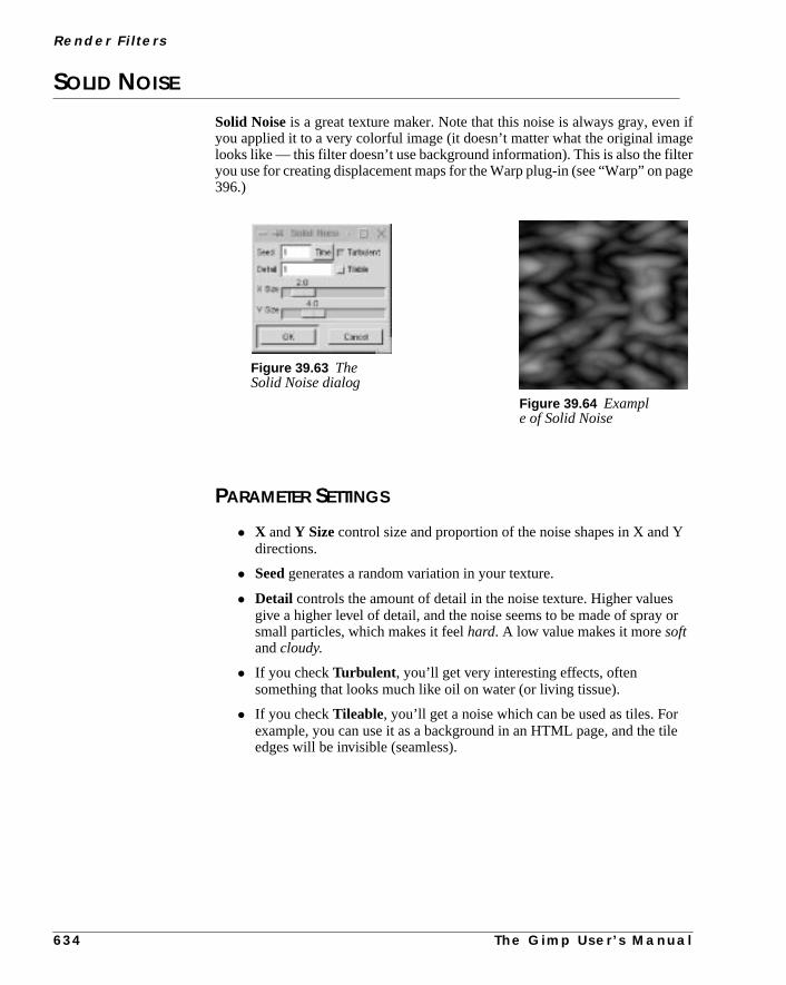
R e n d e r F i l t e r s
n ifgeerage
Y
or
ile
SOLID NOISE
Solid Noiseis a great texture maker. Note that this noise is always gray, eveyou applied it to a very colorful image (it doesn’t matter what the original imalooks like — this filter doesn’t use background information). This is also the filtyou use for creating displacement maps for the Warp plug-in (see “Warp” on p396.)
PARAMETER SETTINGS
• X and Y Size control size and proportion of the noise shapes in X and directions.
• Seed generates a random variation in your texture.
• Detail controls the amount of detail in the noise texture. Higher valuesgive a higher level of detail, and the noise seems to be made of spraysmall particles, which makes it feelhard. A low value makes it moresoftandcloudy.
• If you checkTurbulent , you’ll get very interesting effects, oftensomething that looks much like oil on water (or living tissue).
• If you checkTileable, you’ll get a noise which can be used as tiles. Forexample, you can use it as a background in an HTML page, and the tedges will be invisible (seamless).
Figure 39.63 TheSolid Noise dialog
Figure 39.64 Example of Solid Noise
6 3 4
T h e G i m p U s e r ’ s M a n u a l


P A R T
VII MiscellaneousGimp Functions• HOW TO USE ANIMFRAMES
• XINPUT AND TABLETS


C H A P T E R
40 Advanced Animation With GimpOr How To Use AnimFramesGimp has many excellent tools for makinganimations. The far most advanced of these tools isAnimFrames. We will unleash the power of it in thischapter.

A d va n c e d A n i m a t i o n W i t h G i m p O r H ow To U s e A n i m F r a m e s
ary
er.thes.
ut
sin-achveryme
er has
esyou
utes,
BASIC CONCEPTS
You will find the AnimFrames tool underright-click| AnimFrames . Asthe name indicates, AnimFrames works with image frames. A frame is an ordinGimp image saved with a special extension.
When you make an ordinaryGIF animation you create amulti-layeredimage,where the object that you want to animate moves a little bit for every new layIf you want to use more than one animation object, you have to put all ofobjects in the same layer. This makes it hard to create advanced animation
If you want to work with several objects that can moveindependentlyof eachother, the ordinary Gimp animation filters do not suffice. To find out more abothe Gimp animation filters, read “Animation Filters” starting on page 369.
AnimFrames overcomes this problem in a wonderful way. Instead of using agle multi-layered image, AnimFrames works with several images, where eimage can have several layers with different objects in them. This makes eobject independent of the other animation objects, just like in a cartoon frawhere several people move around independently, because each charactbeen painted on a separate plastic sheet.
HOW TO CREATE AN ANIMATION WITH ANIMFRAMES
MAKING A FRAME
1. The first thing you have to determine when you create an animation is thesizeof the background image. When you’ve made up your mind, selectright-click|File| New, and specify the desired size in the dialog box.
2. AnimFrames is built up offrames, and to turn your image into a frame, youmust firstsave it. Chooseright-click|File| Save as and save thenew image asanimationname_0001.xcf (the special extension forAnimFrames is_0001.xcf ).
3. Now, it’s time to create the frames. Chooseright-click|AnimFrames| Duplicate Frame . This brings up a dialog asking you tospecify how many duplicates you want, or in other words, how many framyou want for your animation (the slide only goes as far as to 50 frames, butcan easily change that by typing a number of frames in the field.)
Format And Save FunctionsThe format must beXCF (Gimp’s native file format), but if you are low on diskspace, you can choose acompressedXCF by adding.gz or .bz to the end of theframe name. To make this work, you must of course have eithergzip or bzip2installed on your system.
Don’t worry about saving; all frames are stored on disk immediately withoexplicit save. The same happens when you work with other tools in AnimFramso you only have to save when youexit AnimFrames.
6 4 0 T h e G i m p U s e r ’ s M a n u a l

C h a p t e r 4 0
mes.
spe-an
s”few
HOW TO NAVIGATE FRAMES
We assume that you have now created a few basic frames, for example, 10 fraWe are in frame number 1 (name_0001.xcf ).
This is certainly something that we want to avoid, so we suggest you use thecial AnimFrames menu commands for navigating the frames instead. You cnavigate in the following ways:
• Goto First will bring you to frame My_anim_0001.xcf
• Goto Next -> My_anim_0002.xcf
• Goto Prev -> My_anim_0001.xcf
• Goto Last -> My_anim_0010.xcf
• Goto Any will bring up a dialog asking you which frame to go to
The author of the plug-in suggests that you assign hotkeys to theGoto com-mands, because you will move around a lot in your frames.
Read more about hotkeys in “Default Shortcuts And Dynamic Key Bindingstarting on page 9. You can choose any key bindings you like, but here are asuggestions:
Goto First Ctrl+Alt+1
Goto Prev Alt+1
Goto Next Alt+2
Goto Any Alt+3
Goto Last Ctrl+Alt+2
Before we start discussing this topic in depth, we must make something veryclear;you must never open two frames in Gimp at the same time!
If your animation is calledMy_anim, always make sure that you don’t openMy_anim_0001.xcf andMy_anim_0002.xcf at the same time.
If you let this happen, things can get really bad, and in the worst scenario,destroy your animation and crash Gimp!
T h e G i m p U s e r ’ s M a n u a l 6 4 1

A d va n c e d A n i m a t i o n W i t h G i m p O r H ow To U s e A n i m F r a m e s
s.
are
rstt. In
’ta-ats
ork
YOUR FIRST ANIMATION
HOW TO MAKE A MOVE PATH
The main tool in AnimFrames is theMove Path tool. This tool allows you tomove your animation object along a specifiedpath. You need at least two thingsto make an animation:
• A set of frames, i.e., your 10My_anim images
• An object to animate
1. To make ananimation object, start by creating a new transparent image(right-click|File| New) and paint a simple object in the center of theimage — a big, red do, for example.
2. Open the first frame (My_anim_0001.xcf ) and select theMove Pathoption in theAnimFrames menu, and the Move Path window will appear.This window is where you control the animation sequence. This simpleexample will help you get a basic understanding of how Move Path workLater in this chapter, we’ll return for a more in-depth description of theMovePath window.
3. In the Source Select field, setSourceImage/Layer to your animationobject. SetHandle to Center,Stepmode to Loop andMode to Normal.
4. Mouse-click somewhere in thepreview window, press theAdd Pointbutton and click somewhere else in the preview window.
5. Now, set the Start Frame slider to yourfirst frame and theEnd Frameslider to yourlastframe. Leave the Layerstack and Preview Frame as theyand pressOK .
You have now created your first animation. The red dot will move from the ficlick-point to the second, and it will use ten frames to complete the movemenorder to view the animation, you must selectAnimFrames| Frames Flat-ten and include all of your frames in theSelect Frame Rangeinput field inthe Frames Flatten dialog.
The second step is to make your frames turn into amulti-layeredimage. Do this byselectingAnimFrames| Frames to Image and choosing all your frames.Now, you can watch the animation with theAnimation Playback filter in theFilters/Animation menu.
If you want to save it as a GIF animation, you will have toindexyour image first.We suggest that you stick toRGB during the whole animation process, and donconvert toIndexed until you’re done. Presently, you can only save your animtions as GIF, but it’s probably only a matter of time before other animation formwill be supported by Gimp.
Note that the animation object must be of thesame typeas the frame. You can’tmix indexed images with RGB images, but an RGB and an RGB alpha will wjust fine. The frame and the object layer don’t need to be of the same size.
6 4 2 T h e G i m p U s e r ’ s M a n u a l

C h a p t e r 4 0
tain, you
1),
k
MOVE BEYOND THE BASICS WITH THE MOVE PATH TOOL
HOW FAR CAN ANIMFRAMES TAKE ME?
There are nearly no limits to what you can achieve with AnimFrame, but cerkinds of animations are harder to create than others. To create some effectsmay have to edit frames by hand.
We’ve made an animation demo (see “Animation Gallery/Tutorial” on page 65where we show a few examples of what AnimFrames is capable of; likepanningthe background, making an aftertext thatrolls over the frame, aperspectiveintrotext, moving objectsawayfrom you andtowardsyou, setting differentspeedstoobjects, etc.
THE ANIMATION STUDIO
TheMove Path window is the heart of AnimFrame, so let’s have a closer looat what it can do and what the parameter settings signify.
The dialog is divided into three different parts:Source Select, Move PathPreviewand a bottom part where you set some slides and buttons.
Figure 40.1 TheMove Path dialog
T h e G i m p U s e r ’ s M a n u a l 6 4 3

A d va n c e d A n i m a t i o n W i t h G i m p O r H ow To U s e A n i m F r a m e s
omne or
rtedodes
d asrnercon-’s
he
ionatent
ber
ewthe
nes.
SOURCE SELECT
SourceImage/LayerThis menu is where you select theanimation object, i.e., the layer or imagewhere your animation object is. You can only open AnimFrames/Move Path fra frame image, so you must keep a frame image (just one!) open, as well as omore object images.
ModeHere, you define how to combine the color/brightness values of the impolayer/image and the rest of the layers in the frame. You can read more about min “Modes” starting on page 335.
HandleThe Handle determines which part of the imported image/layer should be usea point of departure for the move path. Handle is used for locking a certain coof the source layer/image to the move path. If you select top-left handle, thetrol point will stick to the top-left corner of the source layer, forcing the layerposition to the bottom-right side of the control point.
StepmodeStepmode determines the sequence of the animation.Loop creates a continuousanimation from the first control point to the last.Loop reversedoes the same butgoes the other way around — from the end point to the first control point. (OnceandOnce reverseare currently the same as Loop, but that will change with tdevelopment of this plug-in).Ping Pongmakes your animation go from the firstpoint to the last point, back to the position after the first point, to the positbefore the last point and so on.Nonecancels the animation. We recommend thyou stick to Loop and Loop reverse, and control the output by animating differsequences separately, or by exchanging frames.
THE PREVIEW WINDOW
Here’s where the actual setting of the animation takes place. By placing a numof control points along a track, you create a linear movingpath for the object.Note that the path and the points areinvisible. You can only see them by steppingyour way forward or backward with theNext Point/Prev Point buttons.
Tip: If you find it hard to visualize a path created with the mouse in the previwindow, make a freehand drawing of the track to guide you when you placecontrol points. When you have finished the path, you can erase the pencil li
6 4 4 T h e G i m p U s e r ’ s M a n u a l

C h a p t e r 4 0
he
o
n.
omh.re-to
nts.thel-
uma-
save
ointor-
gingck-
in
useu to
Move Path Preview And Control PointsThe animation object will move from the first to the last control point over tframes you set using the slides Start Frame andEnd Frame.
By default, thefirst control point is placed in the top-left corner. If you want tstart from here, continue the path by pressing theAdd Point button to add asec-ondpoint to the path. Then,click in the preview window to set theposition of thesecond control point.
If you don’t want the path to begin from the top-left corner,changethe positionof the first control point by clicking in the preview window to set the new positioTo continue the move path, pressAdd Point, click on a new position to set thesecond control point, and so on.
If you want toadjust the position of a control point, pressPrev Point or NextPoint to navigate the path. The status of the point controls will now change frX[2] to X[1], for example, so you know what control point you are dealing witAdjust the position of the chosen control point by clicking at the spot in the pview window where you want it, and the move path will automatically conformthe new position.
Note: You can’t add a control point to adjust the path between two existing poiYou can only add toprolong the path, so always make sure that you stand atlastcontrol point when you add a new point; otherwise, it will be quite hard to folow the path you’re creating.
If you want to prolong the path by adding another control point, press theNextPoint button until you arrive at the last control point, then pressAdd Point andclick at the place where you want to put it.
Because the animation object’smove pathis determined by the control points, youwill have to use a lot of control points to create a circular path. The maximnumber of control points are 256, but that is quite sufficient for most GIF animtions.
OptionsA very nice option is the possibility tosaveand import control points. Thismakes it possible to let different objects use the same move path (you can alsoyour favorite move path for later use).
You can create a very exact moving path by inserting a value in the control ppositionfieldsX andY. The values here give you the necessary numerical infmation about every point’s position.
Note: The position cross is not restricted to the area inside the preview. Dragit outside of the preview window will, for example, enable you to pane the baground.
TheWidth andHeight controls allow you to resize the layer/image at a certacontrol point. This is, of course, ideal for zooming.
Opacity controls transparency of the object image. You can, for example,this control to fade in and out of images. As you see, these controls allow yocreate many of the common effects you’ve seen in ordinary movies.
T h e G i m p U s e r ’ s M a n u a l 6 4 5

A d va n c e d A n i m a t i o n W i t h G i m p O r H ow To U s e A n i m F r a m e s
le,car
your
iewl is
eandero,set
ards,
A really nice feature is theRotate degoption, which enables you to rotate theanimation layer. With this option it’s very easy tospin an object around.
A Short Example1. Create 50 frames.
2. Create a simple cross in a new image (let the image be 25x25 pixels).
3. OpenMove Path and make 12 control points.
4. Set control point 1 to 0˚, point 2 to 90˚, point 3 to 180˚ and so on.
5. SetSource Image/Layer to the cross image you made.
6. SetHandle to center.
7. Set every control point to be in the center of the preview area.
8. PressOK .
Now you have 50 film frames of a spinning cross. OK, it’s a fairly simple exampbut the function is very versatile. You can easily create a spinning plane, amoving in a circle, etc. It’s just up to your imagination.
CONTROL SLIDES
The Frame SlidebarsThese slidebars control where and how the import layer should be placed inframe. TheStart Frame and End Frame sliders determine which frames theimage/layer (with the current move path) should be imported to. ThePreviewFrame slider controls which frame you’ll see when you press the update prevbutton. Note that this only works for the first and last control points. This toofor viewing the beginning and end of an animation sequence
The LayerstackThe Layerstack slidebar controls in which position the imported layer/imagwill be placed in relation to the other layers in the frame. In order to understthis you must think of the layers as a stack of cards. If the layerstack is set to zthen the layer will end up on top of all other layers (cards). If the layerstack isto 1, then the layer card will be inserted between the first and second layer cetc.
6 4 6 T h e G i m p U s e r ’ s M a n u a l

C h a p t e r 4 0
seedre-
. Afied
ylayerere’s
tecify.
he
typetialionthe
f the
,
emer, ifnot
THE ANIMFRAME MENU
UNDO AND PREVIEW
Other than the preview in the Move Path tool, there is no preview that lets youyour animation while it’s under production (it would be too slow to load anunload images from disk, especially if there are a lot of layers). If you want a pview, you can either step forward with theGotoNext command (use theassigned shortcut command), or create a multi-layered image withFlattenFrames followed by Frames to Image, and view it with right-click|Filters|Animation| Animation Playback .
There is noUndo in AnimFrames, because all frames are saved immediatelyway around this is to always keep your layers in the frames. If you aren’t satiswith a certain frame layer sequence, then you can easily delete it with theFramesLayer Deletecommand.
FRAMES LAYERDEL AND DELETE FRAMES
The Frames LayerDel command will bring up a dialog asking you to specifwhat Frame Range should be affected, and the position of the unwantedsequence in the Layerstack. Be careful here, because when you press OK, thno return.
TheDelete Framescommand will delete the frame that you opened the DeleFrames dialog from. It can also delete the following frames in the range you spe
FRAMES CONVERT
If you want toexportyour frames to different image formats, you can use tFrames Convert command.
The drop-down menu lets you select whether you want to keep the image(RGB) or convert it to a different format (Gray, Indexed or RGB). This is essenif you want to save your frames in GIF format, because GIF images by definitare indexed. The field above the menu is for specifying image format by typingsuffix (such as .gif, .tiff or .jpeg) To verify what frames to convert, use theFromFrame andTo Frame slidebars.
If you want to, you can also set a new base name for the frames in theBasenamefield. Just remember that the basename is the whole path plus the name oimage without the number extension. For example, don’t use/home/me/gap/test_0001.gif , use/home/me/gap/test which is the correct basenamebecause the_0001.gif extension is added automatically.
TheFlatten checkbox flattens the frames before you save them. If you save thas GIF’s, flattening is not necessary, because GIF can handle layers. Howevyou want to save them as TIF images (or any other image format that does
T h e G i m p U s e r ’ s M a n u a l 6 4 7

A d va n c e d A n i m a t i o n W i t h G i m p O r H ow To U s e A n i m F r a m e s
port
num-ed
ttheme
ion,want
iswed
ot;et of
d
the
’t
-
ch
handle layers), you have to flatten the images first, because TIF doesn’t suplayers.
When you save the frames as an indexed image, you can specify the desiredber of colors with theColor slide. You can also let the indexed image be ditherby checking theDither checkbox.
EXCHANGE FRAME
Exchange Frameis used forrearrangingyour frames. In the dialog, set whaframe you want to swap the current frame with. For example, if you invokecommand from frame 3 and set the slide to 5, then frame 3 will end up as fra5, and frame 5 will end up as frame 3.
FRAMES FLATTEN AND FRAMES TO IMAGE
Invoke the Frames Flatten command when you want to preview your animatand the Frames to Image command when your animation is finished and youto save it as a GIF animation.
Frames Flattenwill flatten the layers in each frame. The result of applying thcommand is a sequence of merged (AnimFrames) frames, which can be viestep-by-step withAnimFrames| Goto Next . All frames must be flattenedbefore you can preview your animation using this command.
To create aGIF animation, you can’t use the frames as they are, flattened or nyou’ll need an image composed of several layers to do that.To convert your sflattenedframesto a multi-layeredimage, you must use theFrames to Imagecommand.
When you useFrames Flatten, we recommend that you do this on a copy, annot the original frames (cd ”your frame directory” && mkdirframecopy && cp * framecopy in a terminal window). If you flatten theoriginal frames, you’d better make sure that everything’s OK, because onceframes are flattened there is no way to edit the frame layers.
Frames to Image is a bit more friendly; it creates a new image and wondestroy the original.
Frames To Image OptionsIn theLayer Mergemodeparameter area, you’ll find the most important parameter settings in the Frames to Image dialog box.
• Clipped to image is generally the most efficient option. Clipped toimage will create a multi-layered image from multi-layered frames. Eaframe will be flattened on the fly and merged into a single layer in theresulting multi-layered image. The resulting image will be of the samesize as the frame.
6 4 8 T h e G i m p U s e r ’ s M a n u a l
C h a p t e r 4 0
ed
u’llr.
uld
u
ednfter
kese
e
. In
the
• Flattened imageis nearly the same asClipped to image. The maindifference is that if your animation has transparent parts, they will be fillwith the background color in the toolbox.
• Expand as necessary will enlarge the resulting image if any of theframe layers are outside of the frame canvas.
• Clipped to bottom layer, used with an uncheckedExclude BG-Layer checkbox, can be quite useful. In order to set the size of theanimation, you often start working with an empty bottom layer. As youcreate the animation, you add a lot of layers. When you are finished, yowant to keep thesize of the bottom layer, but not the actual bottom layeIf this is the case,Clipped to bottom layer is the perfect tool.
In theSelect Layer(s)parameter area you can select which frame layers shobe included in the image conversion.
• With the check buttons, pick the layers byPattern or byLayerstackposition. There aretooltips for each selection type, so just point, and yowill get an explanation.
• When you have decided how to search for/select the layers, insert thesearch pattern name or layerstack position numbers in theSelectPattern input field.
FRAME DUPLICATE
As we’ve mentioned before in “Making A Frame” on page 640, this tool is usfor creatingbase framesin an animation. Note that if you are in the middle of aanimation and want to duplicate a frame, the duplicate frames will be inserted athe original frame.
FRAMES CROP, RESIZE AND SCALE
All of these tools work exactly as they would on an ordinary image, but they taeffect onall of your frames. So, think carefully before you press OK, becauthese actions haveno undo!
ResizeandScalewill bring up the old familiar dialogs, just as they would havif you had invoked them on an ordinary image.
Crop is a bit different because you’ll only get a parameters settings dialogorder to use Crop effectively, use a fewguidesto set up your cropmarks in theframe. When you have set those marks, you’ll know what parameters to set inCrop dialog:
• Offset X is the distance from the left side to the first vertical cropmarkandY offset is the distance from the top of the image to the firsthorizontal cropmark.
• New height is the distance from the top cropmark to the bottomcropmark, andNew width is the distance from the left to the rightcropmark.
T h e G i m p U s e r ’ s M a n u a l 6 4 9
A d va n c e d A n i m a t i o n W i t h G i m p O r H ow To U s e A n i m F r a m e s
onsions
ur
arch
o in
SPLIT IMG TO FRAMES
This is a very versatile tool. You can use it to convert MPEG and GIF animatito frames and thereby edit animations more easily. There aren’t many opthere, the main thing is to set theextension(image type), but the default extension(which is XCF) is often the best choice.
Parameter Settings
• Inverse order means that the top layer will be frame 1 and thebackground layer will be the last frame. You will have to check how yoanimation is stored to determine what type of order you need.
• Flatten doesn’t really flatten. If any of the layers that will become aframe contain transparent areas, those areas will be filled with thebackground color from the toolbox.
FRAMES MODIFY
If you want tomodify several frames at once, this is the command to use.
Parameter Settings1. First, use the sliders to specify therange; that is, which frames should be
affected by the operation.
2. Then, with theSelect Layer(s) check buttons, pick the layers byPatternor byLayerstack position. There aretooltipsfor each selection type, so justpoint, and you will get an explanation.
3. When you have decided how to search for/select the layers, insert the sepattern name or layerstack position numbers in theSelect Pattern field.
4. Check theCase sensitive checkbox if you want to differentiate layernames with or without capital letters.
5. If you want to perform the operation on frames that youhaven’tselected,checkInvert Selection.
6. When you have set all of these parameters, it’s time to choose what to dtheFunction drop-down menu. If you choose therename Layer(s) option,you also have to specify the new name in the New Layername field. If youchoose theapply filter on Layer(s) option, then theright-click|Filters|Animation| Filter All Layers dialog will appear(see “Filter All Layers” on page 371).
FRAMESEQUENCE SHIFT
This filter will shift your frames just like you shift cards in a deck of cards.
6 5 0 T h e G i m p U s e r ’ s M a n u a l
C h a p t e r 4 0
artings (
ou
’s
If
n the
must
with
:
ra.
Suppose that you have 9 frames and you want to shift the frame sequence stfrom frame 2 and ending in frame 7. You want to move this sequence 2 stepN= 2 in the dialog).
Then, frame 2 will be the new frame 4, frame 3 will become frame 5, etc. until yreach frame 8 which will be frame 2 and frame 9 which will now be frame 3.
FILTER LAYERS
USING A SCRIPT OR FILTER
There is aScript-Fu that can be very useful when dealing with animations. Itthe right-click|Script-Fu|Animators| Sel To AnimImagescript, which lets you apply any filter (plug-in) on all layers in an image.
You may think this is equal toright-click|Animation| Filter AllLayers (see “Filter All Layers” on page 371), but that isn’t completely true.you want to apply a filter smoothly in each layer, theSelection to AnimImagescript is the better choice.
ExampleYou have ten layers and you want to applyright-click|Filters|Dis-tort| Whirl with slightly different values to each layer. If you useFilter allLayers, you have to do this by hand, but if you useSel To AnimImage, you onlyhave to set the start and end values. The script will calculate the values betweestart and end layers, and create a smooth transition.
These operations can only be performed on an image, not on frames, so youfirst convert your frames with theFrames to Imagecommand. When you arefinished, you can easily transform it back to frames with theSplit Image toFrames command.
ANIMATION GALLERY/TUTORIAL
We have made a little animation to show you some of the things you can doAnimFrame. The animation is 186 frames long.
ZoomingThe animation begins with a logo that moves toward you before itbouncesback,stretches out and finallyfades away. Those effects were quite easy to achieve
We started by specifying a low value forWidth andHeight in the first point inthe logo’sMove Path, so that the logo would appear to move toward the came
T h e G i m p U s e r ’ s M a n u a l 6 5 1

A d va n c e d A n i m a t i o n W i t h G i m p O r H ow To U s e A n i m F r a m e s
ne byn wet
e textit’s
nd
final
The fade away/stretch effect was created by setting theopacity in the final pointto 0%, theX scale to 200 and theY scale to 0.
FadingThe next phase in the animation was tofade overfrom the background in thebouncing logo scene to the space background in the next scene. This was doplacing the space background in the lowest layer in a series of 10 frames, themade aMove Pathwith the blue logo background with 100% opacity in the firscontrol point and 0% opacity in the final control point.
StarWars TextThen, we amused ourselves by creating a paraphrase of the rolling perspectivin a movie we assume you’ve never heard of. (Don’t bother reading the text;quite meaningless).
For theperspectiveeffect we used an image that was higher than the frame, athen we skewed the text with theTransform/Perspective tool. TheMove Path(center handle) begins a bit below the actual frame, and the second andpoints, were placed a bit below the center of the image.
Figure 40.2 The object seems tobe moving towards the camera
Figure 40.3 To make theobject fade away, you will haveto use a variable amount ofopacity
Figure 40.4 Blending scenes isvery easy; you just adjust theopacity of the top layer
6 5 2 T h e G i m p U s e r ’ s M a n u a l
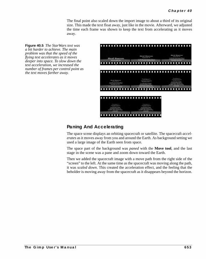
C h a p t e r 4 0
naltedoves
we
f theath,
theizon.
The final point also scaled down the import image to about a third of its origisize. This made the text float away, just like in the movie. Afterward, we adjusthe time each frame was shown to keep the text from accelerating as it maway.
Paning And AcceleratingThe space scene displays an orbiting spacecraft or satellite. The spacecraftaccel-eratesas it moves away from you and around the Earth. As background settingused a large image of the Earth seen from space.
The space part of the background waspanedwith the Move tool, and the laststage in the scene was a pane and zoom down toward the Earth.
Then we added the spacecraft image with a move path from the right side o“screen” to the left. At the same time as the spacecraft was moving along the pit wasscaled down. This created the acceleration effect, and the feeling thatbeholder is moving away from the spacecraft as it disappears beyond the hor
Figure 40.5 The StarWars text wasa bit harder to achieve. The mainproblem was that the speed of theflying text accelerates as it movesdeeper into space. To slow down thetext acceleration, we increased thenumber of frames per control point asthe text moves farther away.
T h e G i m p U s e r ’ s M a n u a l 6 5 3

A d va n c e d A n i m a t i o n W i t h G i m p O r H ow To U s e A n i m F r a m e s
ound,
Fading AgainNow, it’s time for some propaganda in theHelp Us Fight the Evil Empirefade-outscene. This text was faded in the same fashion as the bouncing logo backgronly in reverse direction.
Figure 40.6 To make the spacecraftaccelerate in its orbit, we had to use acombination of two layers. Thebackground layer displaying theEarth, and another layer showing thespacecraft.
The spacecraft was made to movefrom one side to the other while it waszoomed out. At the same time, theEarth was paned in the backgroundlayer.
Figure 40.7 The Evil Empiresequence was made using the sametechnique as in Figure 40.4
6 5 4 T h e G i m p U s e r ’ s M a n u a l

C h a p t e r 4 0
ook.and
ove
n be
Moving AroundThe final scene displays the production team behind this animation, and this bThe Frozenriver logo was made to circulate around the word “Production”fade away at the same time. This was done by using“Production” as a back-ground. The logo was then made to move around the text in a five-point mpath, where the opacity was lowered for each control point.
Note: This animation demo comes both in GIF and AnimFrame format, and cadownloaded fromftp://manual.gimp.org/pub/manual .
Figure 40.8 This effect is very simple toachieve. The control points were placedaround the center, and the transparencywas increased while the object moves.
T h e G i m p U s e r ’ s M a n u a l 6 5 5


C H A P T E R
41 Drawing Tablets And GimpIn this chapter, we will show you how to use adigitized drawing tablet in Gimp. The X extension thatlet us use tablets in Gimp is called Xinput. We willshow you how to enable and configure Xinput andtablets in Linux with XFree86 as Xserver.

D r a w i n g Ta b l e t s A n d G i m p
AD.p is
ds,s.
X
asrsinceion in
ngly
rre)bletuse,
li-lso
INTRODUCTION
WHAT IS A DRAWING TABLET?
When we speak about a tablet, we refer to a digitizeddrawing tabletin combina-tion with a digital pen. This pen can bepressure sensitive, which means thatif you press harder, the pencil stroke will get thicker.
There are other kinds of tablets that operate without pens, such as tablets for CHowever, for working in Gimp, you’ll need a pen-enabled tablet, because Gima program for graphic artists.
Platforms And BrandsWe will review Wacomtablets in this chapter. There are naturally other bransuch asSummaSketch, but due to hardware limits we will focus on Wacom tabletWe will cover all types of Wacom tablets fromArtPadto the latestIntuostablet.
Secondly, we will only discuss configuration and installation underLinuxXFree86; it will, however, most likely be the same for all other versions of UNIthat can use XFree86.
There is support for Xinput in most major Unix/X11 implementations, suchSolaris, OSF/1, HP-UXandAIX, but the main problem is that there are no drivethat enable you to use Wacom tablets. Wacom makes drivers for IRIX, but swe have no access to SGI machines, we are unable to continue the discussthat direction.
What About USB Tablets?Linux support ofUSB (Universal Serial Bus) is very limited at the time ofwriting. There are, to our knowledge, no supported USB tablets, so we strorecommend that you buy a Serialport tablet instead.
INSTALLING AND CONFIGURING
First of all, Gimp 1.0.x doesn’t support tablets(even though the current developeversion has tablet support, and the next Gimp release will include this featu.This limits the usage, but does not prevent it. There are two ways of using a tain Gimp 1.0.x. The simplest way is to use the pen as a complement to the mobut then you will not be able to bring the pressure sensitivity into play.
If you want to make full use of the pen’s capabilities, you will have topatchandcompileGimp yourself. However, this is no trivial task. It can get very compcated if you have an old version of X11 (XFree86), because then you will ahave torecompile X11.
6 5 8 T h e G i m p U s e r ’ s M a n u a l

C h a p t e r 4 1
tilld totocoms
1.2Drsioneen
witchoint-
thatd
esion
issure
asy
ht
sentow
USING THE PEN AS A MOUSE REPLACEMENT
Without pressure sensitivity the pen is an incomplete instrument, but it will simprove the precision and ease of freehand drawing immensely comparedrawing with your mouse. This section provides you with information on howuse a digitized pen as a replacement or complement to the mouse with all Watablets, except theIntuostablet, which will be discussed in “The Wacom IntuoTablet” on page 671.
THE RIGHT XFREE86 VERSION
Xinput and Wacom tablets have been supported by XFree86 since the 3.release. However, we always recommend getting the latest and greatest ve(which at the time of writing is 3.3.3.1), because many new features have badded and bugs resolved.
One of the most notable new features is theSwitch/AlwaysCorefunction, whichmakes it possible to use the pen and the mouse at the same time. You can sbetween the mouse and the pen without having to specify which one is your ping device.
If you don’t have XFree86 3.3.3, or never installed it, we strongly recommendyou upgrade. Otherwise, you’ll find that working with your tablet will be slow ancumbersome.
In relatively new Linux distributions, most major Linux distributors includupgrade packages that will make it relatively easy to upgrade to XFree86 ver3.3.3 or newer.
We will cover the basic configuration of tablets within the XF86Config file. Thsection is required for all tablets, including the Intuos tablet and/or when pressensitivity is enabled.
WITHOUT AUTO SWITCH BETWEEN MOUSE AND PEN
If you didn’t upgrade to 3.3.3., you can’t use theauto switchwhen changing frommouse to pen and vice versa. The XFree86 config file will in this case be very eto configure.
The XF86Config file can be found in the following locations:
/etc/ XF86Config
/usr/X11R6/lib/X11/ XF86Config(most of the time this file is symlinked to/etc/X11/XF86Config ).
TheXserver will search for the file in the same order, so be sure to edit the rigfile (i.e., if you have a/etc/XF86Config file, don’t edit the/usr/X11R6/lib/X11/XF86Config file).
Most of the time the config data for Xinput and Wacom tablets are already prein the XF86Config file, and are just being commented out. We will describe h
T h e G i m p U s e r ’ s M a n u a l 6 5 9
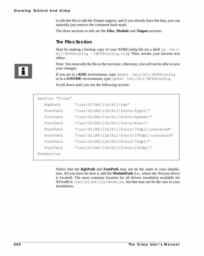
D r a w i n g Ta b l e t s A n d G i m p
can
ave
-
forr
to edit the file to add the Xinput support, and if you already have the data, younaturally just remove the comment hash mark.
The three sections to edit are theFiles, Module andXinput sections.
The Files SectionStart by making a backup copy of your XF86Config file (in a shellcp /etc/X11/XF86Config ~/XF86Config.old ). Then, invoke your favorite texteditor.
Note: You must edit the file as the root user; otherwise, you will not be able to syour changes.
If you are in aKDE environment, type:kedit /etc/X11/XF86Configor in aGNOME environment, type:gedit /etc/X11/XF86Config .
Scroll down until you see the following section:
Notice that theRgbPath andFontPath may not be the same in your installation. All you have do here is add theModulePath (i.e., where the Wacom driveris located). The most common location for all drivers (modules) availableXFree86 is/usr/X11R6/lib/modules , but that may not be the case in youinstallation.
Section “Files”
RgbPath “/usr/X11R6/lib/X11/rgb”
FontPath “/usr/X11R6/lib/X11/fonts/Type1/”
FontPath “/usr/X11R6/lib/X11/fonts/Speedo/”
FontPath “/usr/X11R6/lib/X11/fonts/misc/”
FontPath “/usr/X11R6/lib/X11/fonts/75dpi/:unscaled”
FontPath “/usr/X11R6/lib/X11/fonts/100dpi/:unscaled”
FontPath “/usr/X11R6/lib/X11/fonts/75dpi/”
FontPath “/usr/X11R6/lib/X11/fonts/100dpi/”
EndSection
6 6 0 T h e G i m p U s e r ’ s M a n u a l

C h a p t e r 4 1
you
you
k
To check it out, executels -l /usr/X11R6/lib/modules/ in a shell.This will probably render the following output:
If you don’t get this output, your drivers (modules) are located elsewhere andwill have to find them by executing something like:
find /usr/X11R6/ -name xf86* -print
in a shell. The file list above may not be exactly the same on your system, butmust have a file namedxf86Wacom.so, since it’s the Wacomtablet driver .
Add the following entry to the files sectionModulePath:
“/usr/X11R6/lib/modules/”
The path, i.e.,“/usr/X11R6/lib/modules/” , should naturally reflect the direc-tory where you have your drivers (modules). The XF86Config file will now loolike this:
[olof@whopp olof]$ ls -l /usr/X11R6/lib/modules/
total 1157
-rwxr-xr-x 1 root root 552962 Oct 10 1998 pex5.so
-rwxr-xr-x 1 root root 14192 Oct 10 1998 xf86Elo.so
-rwxr-xr-x 1 root root 13634 Oct 10 1998 xf86Summa.so
-rwxr-xr-x 1 root root 24411 May 12 14:22 xf86Wacom.so
-rwxr-xr-x 1 root root 565762 Oct 10 1998 xie.so
[olof@whopp olof]$
Section “Files”
RgbPath “/usr/X11R6/lib/X11/rgb”
FontPath “/usr/X11R6/lib/X11/fonts/Type1/”
FontPath “/usr/X11R6/lib/X11/fonts/Speedo/”
FontPath “/usr/X11R6/lib/X11/fonts/misc/”
FontPath “/usr/X11R6/lib/X11/fonts/75dpi/:unscaled”
FontPath “/usr/X11R6/lib/X11/fonts/100dpi/:unscaled”
FontPath “/usr/X11R6/lib/X11/fonts/75dpi/”
FontPath “/usr/X11R6/lib/X11/fonts/100dpi/”
#Setting the ModulePath
ModulePath “/usr/X11R6/lib/modules/”
EndSection
T h e G i m p U s e r ’ s M a n u a l 6 6 1

D r a w i n g Ta b l e t s A n d G i m p
1).
ith
t-
eget
The Module SectionThe next step is to load/enable the driver/module for use within XFree86 (X1The section in the XF86Config file that takes care of that, is theModule section.In a standard XF86Config file, this section is not present or commented out wa #. We have ourModule section above thePointer section.
Here is an example that you can copy into your XF86Config file(don’t copy thePointer section).
The Xinput SectionNow, you have to enable thepen/tabletas an extension to X11 (as an Xinpudevice). You do that in theXinput section. This section is not present or commented out in the standard XF86Config file.
We have added theXinput section right after thePointer section. As in theModule section, we provide an example for you to copy into your config file. Wwill talk about options and settings later, but we guess that you are eager tostarted and use your pen:
Here is an example that you can copy into your XF86Config file(don’t copy thePointer section).
#Copy from here
Section “Module”
Load “xf86Wacom.so”
EndSection
#to here -- don’t include the “Pointer” section
Section “Pointer”
Protocol “Mouseman”
Device “/dev/mouse”
EndSection
6 6 2 T h e G i m p U s e r ’ s M a n u a l

C h a p t e r 4 1
ure
our
t the
ressreo do
Actually, you don’t need all of it, but it’s better to be prepared to enable presssensitivity, isn’t it?
You’re still not quite ready to start using your pen. First, you have to connect yWacom tablet to the rightserial port of your computer. According to our configfile it will be the ttyS0 serial port (COM1underDOS/Windows). If you haveconnected your Wacom tablet tottyS1 (COM2under DOS/Windows), you haveto replacettyS0 with ttyS1 in the config file.
If you are all done now,restart your Xserver in order to load the driver andenable your tablet. You must, of course, save the config file before you restarXserver.
The simplest way to restart the Xserver, and the whole Linux computer, is to pCtrl+Alt+F2 and Ctrl+Alt+Delete. This will restart the whole computer, so befoyou do it, make sure to save all current work. There are more elegant ways tthis in a Unix/Linux environment, but this is an easy solution for a beginner.
Section “Pointer” Protocol “Mouseman” Device “/dev/mouse”EndSection
#Copy from here
Section “Xinput” SubSection “WacomStylus” Port “/dev/ttyS1” DeviceName “Wacom” Mode Absolute Suppress 6 EndSubSection SubSection “WacomCursor” Port “/dev/ttyS1” Mode Absolute Suppress 6 EndSubSection SubSection “WacomEraser” Port “/dev/ttyS1” Mode Absolute Suppress 6 EndSubSection
EndSection
#to here i.e don’t include the “Pointer” section
T h e G i m p U s e r ’ s M a n u a l 6 6 3

D r a w i n g Ta b l e t s A n d G i m p
er
the
nd
ble
9,
exe-thefor
t” on
ile,new
s a
e thatuto
pent
int-
n’t it?to theuali-
ute.s noto
Using The Pen In GimpYou don’t have to configure or rebuild Gimp. All you have to do now is empowthe pen. This is done withxsetpointer. If you have heeded our configurationexample, you will be able to use the pen by entering the commandxset-pointer Wacom in a shell, while you run X.
The digitized pen will now be your pointing device. You can set the buttons onpen to emulate the mouse buttons; for example, enterxmodmap -e “pointer= 1 4 3 2” to reset the pen buttons. To switch back to your mouse, enterxset-pointer Pointer . This sets the pen tip to button 1, the eraser to button 2, athe pen button to button 3.
As you may realize, this way of working is a real pain. The right way is to enaauto switch between the mouse and the pen.
ENABLING AUTO SWITCH BETWEEN MOUSE AND PEN
If you haven’t read “Without Auto Switch Between Mouse And Pen” on page 65do so now, because we will only cover the differences here.
First of all, you must haveXFree86 3.3.3or newer installed on your Linux sys-tem. An easy way to find out what version you have is to read the man page;cuteman XFree86 , scroll down to the end of the page and read what versionman page was written for. Most Linux distributors provide upgrade packagesenabling a smooth and easy upgrade to XFree86 3.3.3 or newer. See “Xinpupage 881 to find out where to pick up your upgrade.
Because you will already have enabled tablet support in your XF86Config fand we assume that you have tested it, all you have to do now is add someentries in the config file. The only thing you need to edit is theXinput section.
Next, you’ll find an example of an Xinput section that you can copy and use atemplate for your own entries.
As you can see, we have added several subsections containing a Core devicis inAlwaysCore“mode.” This device and setting is what causes XFree86 to aswitch from the mouse to the pen when you let go of the mouse and touch theinstead (and vice versa). Nowrestartyour Xserver, and you will be able to test iout.
XFree86 will now automatically switch and enable you to use the selected poing device instantly — no need to executexsetpointer anymore.
Auto Switch In GimpAuto switch between mouse and pen makes everything so much easier, doesYou can instantly shift between the advantage of having fast and easy accessmenus (using the mouse) and being able to use the pen’s superior painting qties.
There is no configuration that you must perform and no commands to execHowever, you can still only use the pen as an ordinary pointing device; there ipressure sensitivity. Although this is undeniably better than when you had
6 6 4 T h e G i m p U s e r ’ s M a n u a l

C h a p t e r 4 1
nts.ow.
switch between mouse and pen manually, there is still room for improvemeYou can get pressure sensitivity in Gimp, and the next passage will tell you h
Section “Xinput”
SubSection “WacomStylus”
Port “/dev/ttyS1”
DeviceName “Wacom”
Mode Absolute
Suppress 6
EndSubSection
SubSection “WacomStylus”
Port “/dev/ttyS1”
DeviceName “WacomCore”
Mode Absolute
AlwaysCore
Suppress 6
EndSubSection
SubSection “WacomCursor”
Port “/dev/ttyS1”
Mode Absolute
Suppress 6
EndSubSection
SubSection “WacomCursor”
Port “/dev/ttyS1”
DeviceName “CursorCore”
AlwaysCore
Mode Absolute
Suppress 6
EndSubSection
SubSection “WacomEraser”
Port “/dev/ttyS1”
Mode Absolute
Suppress 6
EndSubSection
T h e G i m p U s e r ’ s M a n u a l 6 6 5

D r a w i n g Ta b l e t s A n d G i m p
agesng
witchox.ool.
ore,to
ut”
-
ledirec-oll ofrse
cku-you
PRESSURE SENSITIVITY AND AUTO SWITCH BETWEEN TOOLS
Before you start reading here, you should first read and comply with the pass“Without Auto Switch Between Mouse And Pen” on page 659 and “EnabliAuto Switch Between Mouse And Pen” on page 664.
Having followed these instructions, you will have theXinput support that Gimpneeds to enable pressure sensitivity and auto switch between tools. The auto sfunction will also enable you to assign the pen to a certain tool in the Gimp toolbYou can, for example, easily map the eraser part of your pen to the eraser t
This section will cover all Wacom tablets except the new Intuos tablet. As befyou will still need the XFree86 3.3.3 or newer, but this time you will also needenableXinput in Gtk andpatchGimp. See “FTP” on page 880 for where todownload Gimp and Gtk. You will also need a special Gimp patch. See “Xinpon page 881 to learn where, find the most up-to-date version of this patch.
Xinput Support In GtkGtk already has support forXinput , so all you have to do is enable it, i.e., configure it using--with-xinput=xfree andrecompileit. We recommend thatyou make a special Gimp install directory where you install both Xinput- enabGtk and Gimp. Furthermore, it is a good idea to have another personal Gimp dtory than the usual.gimp in your home directory. Here is an example of how tuncompress, extract, configure, compile and install Gtk with Xinput support (athis is done in a terminal window such as xterm). Your commands may of coube slightly different, but basically it will be the same procedure.
Compilation ProblemsIf your compilation failed, it could be for a number of reasons. First of all, chethat you have all of the X11 development files available for your Gimp distribtion. There are variations between the different distributions, so we can’t givean exact instruction on how to check this. However, if you have usedrpm as aninstallation tool, you can tryrpm -q -a | grep X .
[olof@whopp olof]$ gunzip gtk+-1.0.6.tar.gz
[olof@whopp olof]$ tar xvf gtk+-1.0.6.tar
[olof@whopp olof]$ cd gtk+-1.0.6
[olof@whopp gtk+-1.0.6]$ ./configure --prefix=/opt/gimpinput \
--with-xinput=xfree
[olof@whopp gtk+-1.0.6]$ make
[olof@whopp gtk+-1.0.6]$ su root -c “make install”
Note: You must provide the root password
[olof@whopp gtk+-1.0.6]$
6 6 6 T h e G i m p U s e r ’ s M a n u a l

C h a p t e r 4 1
48.-
ro-
ak-
e
In our Linux distribution this command would result in a line like this:
XFree86-devel-3.3.3
Your result may differ slightly, but the string to look for isXFree86-devel .
We also recommend that you read “Installing A Source Distribution” on pageHere, you will find a lot of useful information concerning compilation and common compilation problems.
XINPUT SUPPORT IN GIMP
We need to enableXinput support in Gimp in order to obtain auto switchingtools and pressure sensitivity. You will have topatchGimp and rebuild it fromscratch. This is not a trivial task, but we hope that by guiding you through this pcedure, we will make it as easy as possible for you.
Patching GimpStart by downloadingGimp 1.0.2 and the specialGimp Xinput patch . Wesuggest that you to read “Installing A Source Distribution” on page 48 before ming any attempt to patch, configure and make Gimp.
Okay, ready to give it a try? We will, as usual, give you an example to follow. Wassume that you have both Gimp and the patch in your home directory.
T h e G i m p U s e r ’ s M a n u a l 6 6 7

D r a w i n g Ta b l e t s A n d G i m p
o
After this you have to edit theMakefile in theapp directory. Just rungedit orkedit app/Makefile . Scroll down until you find:
desaturate.h \
Now, you have toinsert two lines after thedesaturate.h line. Followingis an example of what it will look like. Did you notice the backslash “\ ” sign?When you insert this sign it tellsmake that it shouldskip the next character(which in this case is thenewlinecharacter or enter). The important thing tremember is that you must insert an enter directly after the “\ ”sign. If there is aspace or other character than the newline character (enter),makewill fail to com-pile Gimp.
[olof@whopp olof]$ gunzip gimp-1.0.2.tar.gz
[olof@whopp olof]$ tar xvf gimp-1.0.2.tar
[olof@whopp olof]$ gunzip patch-gimp-xinput.10.gz
[olof@whopp gimp-1.0.2]$ cd gimp-1.0.2
[olof@whopp gimp-1.0.2]$ patch -p1 < ../patch-gimp-xinput.10
patching file `app/Makefile.am’
patching file `app/app_procs.c’
Hunk #1 succeeded at 32 (offset 4 lines).
Hunk #2 succeeded at 510 (offset 16 lines).
patching file `app/brushes.c’
[snip]
patching file `app/tools.h’
Hunk #1 succeeded at 135 (offset 4 lines).
patching file `app/undo.c’
[olof@whopp gimp-1.0.2]$ ./configure --prefix=/opt/gimpinput \
--with-gtk-prefix=/opt/gimpinput --disable-gtktest \
--enable-gimpdir=.gimpinput
[olof@whopp gimp-1.0.2]$
6 6 8 T h e G i m p U s e r ’ s M a n u a l

C h a p t e r 4 1
-ier.
As you see, we have inserted two new lines:devices.c anddevices.h .Now, continue to scroll down until you finddesaturate.o . Now, insertdevices.o afterdesaturate.o . See the example below:
All you have to do now is compile and install Gimp:
Running The New GimpBefore you can run Gimp with Xinput support, you have to create astart-up fileor set yourLD_LIBRARY_PATH every time you want to start Gimp. We recommend creating a start-up file, because it will make your Gimp life so much easCreate this file calledGimp in /opt/gimpinput/bin (open gedit orkedit , copy the example provided by us, and save it asGimp in your homedirectory):
desaturate.c \
desaturate.h \
devices.c \
devices.h \
dialog_types.h \
disp_callbacks.c \
colormaps.o commands.o convert.o convolve.o crop.o cursorutil.o \
curves.o datafiles.o desaturate.o devices.o disp_callbacks.o\
draw_core.o drawable.o drawable_cmds.o edit_cmds.o \
[olof@whopp gimp-1.0.2]$ make
[olof@whopp gimp-1.0.2]$ su root -c “make install”
Note: You must provide the root password
[olof@whopp gimp-1.0.2]$
#!/bin/sh
LD_LIBRARY_PATH=/opt/gimpinput/lib export LD_LIBRARY_PATH
exec /opt/gimpinput/bin/gimp “$@”
T h e G i m p U s e r ’ s M a n u a l 6 6 9
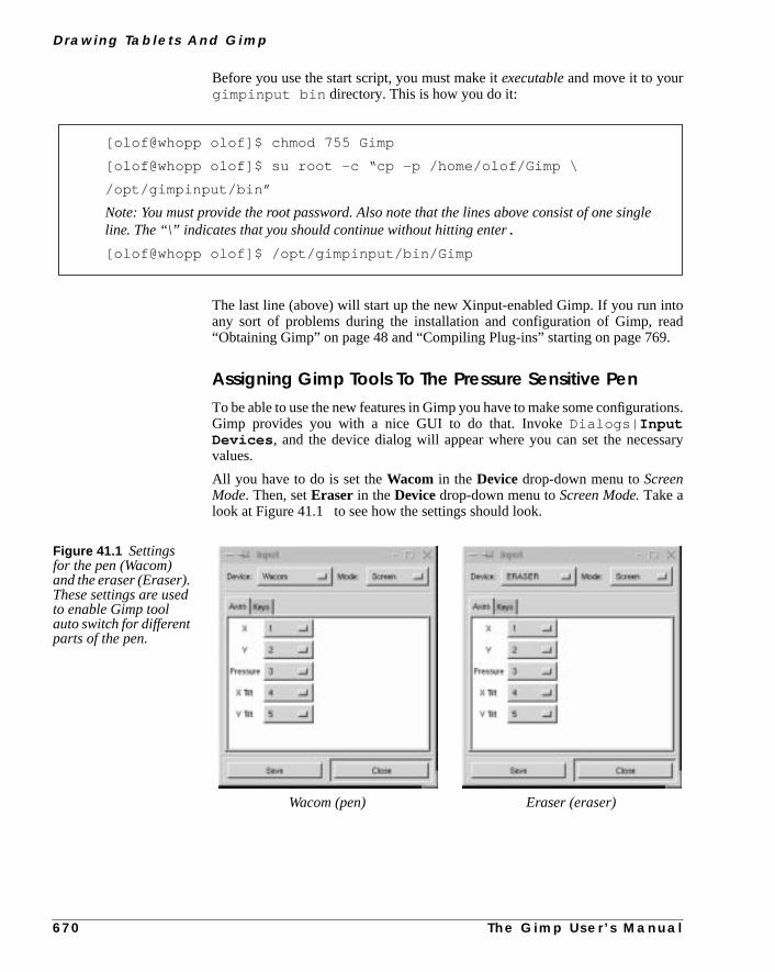
D r a w i n g Ta b l e t s A n d G i m p
toad.
ions.
sary
le
Before you use the start script, you must make itexecutableand move it to yourgimpinput bin directory. This is how you do it:
The last line (above) will start up the new Xinput-enabled Gimp. If you run inany sort of problems during the installation and configuration of Gimp, re“Obtaining Gimp” on page 48 and “Compiling Plug-ins” starting on page 769
Assigning Gimp Tools To The Pressure Sensitive PenTo be able to use the new features in Gimp you have to make some configuratGimp provides you with a nice GUI to do that. InvokeDialogs| InputDevices , and the device dialog will appear where you can set the necesvalues.
All you have to do is set theWacom in the Devicedrop-down menu toScreenMode. Then, setEraser in theDevicedrop-down menu toScreen Mode.Take alook at Figure 41.1 to see how the settings should look.
[olof@whopp olof]$ chmod 755 Gimp
[olof@whopp olof]$ su root -c “cp -p /home/olof/Gimp \
/opt/gimpinput/bin”
Note: You must provide the root password. Also note that the lines above consist of one singline. The “\” indicates that you should continue without hitting enter.
[olof@whopp olof]$ /opt/gimpinput/bin/Gimp
Figure 41.1 Settingsfor the pen (Wacom)and the eraser (Eraser).These settings are usedto enable Gimp toolauto switch for differentparts of the pen.
Wacom (pen) Eraser (eraser)
6 7 0 T h e G i m p U s e r ’ s M a n u a l

C h a p t e r 4 1
tool
-
er),of the
impgs. Aow-
sen-the
h as
dnds
cand with
y the
When you are done, press Save and then Close. Now, we will assign a Gimpto the end part of the pen (where there is an eraser on a real pencil).
Bring up the Device Status dialog usingDialogs| Device Status . Bringup a new image in Gimp usingFile| New, move the pen over the tablet and navigate so that the cursor points to the new image. TheWacombutton will now beenabled in the Device Status dialog box.
Select the brush tool in the toolbox. Turn the pen around (point with the erasrepeat the same steps as before, but this time enable the eraser tool insteadbrush tool. Grab the mouse and pressSave in the Device Status dialog.
You are now ready to use your tablet, but remember that this is a patched Gand that the pressure sensitivity can be a bit crude. There may also be buknown bug is that the Device Status dialog doesn’t get updated as it should. Hever, this bug does not affect the functionality. The only tool that is pressuresitive is the brush; the other tools (such as the eraser) will just benefit fromconvenient auto switching feature.
THE WACOM INTUOS TABLET
WHAT IS INTUOS?
Intuosis Wacom’s latest tablet. It includes several new tools and features suctool-ID (auto recognition of which pen you are using),Airbrush , a special4Dmouse, and of course, the digitalpen. There are also more buttons integratewith the pen, which makes it easier to work in an X11 environment that demathree buttons.
All of those features are not supported in Gimp or XFree86. Naturally, youstill use the pressure-sensitive pen, the eraser and the 4Dmouse as you woulan ordinary Wacom tablet.
The development version of Gimp,Gimp 1.1.x, which is still not ready foreveryday use, has a much better support for Wacom tablets and especiallIntuos tablet (see “A Sneak Preview Of Gimp 1.1.x” on page 674).
Figure 41.2 Gimp’s Device Status dialog
T h e G i m p U s e r ’ s M a n u a l 6 7 1

D r a w i n g Ta b l e t s A n d G i m p
Theuto
or
thatarm
thouour
sup-
ve
ENABLING INTUOS SUPPORT IN XFREE86
Before you enable Intuos support, read and comply with the sections “UsingPen As A Mouse Replacement” on page 659 and “Pressure Sensitivity And ASwitch Between Tools” on page 666.
Don’t restart X11 until we tell you to in the following example. As far asIntuos is concerned, you don’t need to worry if you don’t have XFree86 3.3.3newer, as long as you have (at least) XFree86 3.3.2.
In XFree86 3.3.3.1 there is an early beta driver for Intuos, but we recommendyou get the latest development version of the driver (which works just like a chfor us). See “Xinput” on page 881 to find out where to download it from.
On A Glibc-Based SystemIf you are on aGlibc-based system, there are precompiled drivers for boXFree86 3.3.2 and 3.3.3; otherwise, you will have to recompile XFree86. If yare on a Glibc-based system, just download the precompiled driver for yXFree86 version and copy it to yourmodule directory:
Now, you can restart your Xserver and/or computer to empower the Intuosport.
Finding Out If Your System Is A Glibc SystemWhat if you don’t have a Glibc Linux system, and how do you find out if you haone? To check if you have a Glibc system, you only have to enter anls com-mand, like this:
[olof@whopp olof]$ chmod 755 xf86Wacom.so
[olof@whopp olof]$ cp -p /usr/X11R6/lib/modules/xf86Wacom.so \
xf86Wacom.so.old
[olof@whopp olof]$ su root -c “xf86Wacom.so \
/usr/X11R6/lib/modules/”
Note: You must provide the root password. Also note that the linesabove consist of a single line. The “\” indicates that you shouldcontinue without hitting enter.
[olof@whopp olof]$
6 7 2 T h e G i m p U s e r ’ s M a n u a l

C h a p t e r 4 1
.
i.e.,fthe
r
thensys-om
our
aved
If your commands inform you that you havelibc-2.0.x.so and ld-2.0.x.so (where x is a number), then you do have a Glibc-based system
On A Non-Glibc SystemIf you don’t have those files, then you have to get the source code of the driver,the xf86Wacom.c file. You also have to get source code distribution oXFree86. See “Xinput” on page 881 for where to download both the driver andXFree86 source code distribution from.
First uncompressandextractyour XFree86 3.3.3.1 source code distribution (onewer; we assume you didn’t download an old one). Then, copyxf86Wacom.cto thexc/programs/Xserver/hw/xfree86/common/ directory.
If you already have XFree86 3.3.2 or 3.3.3, 3.3.3.1, but not a Glibc system,it may be wise to download the XFree86 source distribution that matches yourtem. This will save a lot of time, because you’ll only need to rebuild the Wacdriver.
If you have downloaded a source distribution of XFree86 that matches yXFree86 version and copiedxf86Wacom.c to the right directory, all you haveto do is:
Now, copy the driver to the right directory, as we did before in this section.
If you have a non-Glibc system as well as an old XFree86 version, then you hto recompileandinstall the whole XFree86 distribution, and that is really beyonthe scope of this book.
[olof@whopp olof]$ ls -l /lib/libc.*
lrwxrwxrwx 1 root root 13 Jan 8 20:43 \
/lib/libc.so.6 -> libc-2.0.7.so
[olof@whopp olof]$ ls -l /lib/ld-2*
-rwxr-xr-x 1 root root 160241 Oct 13 1998 \
/lib/ld-2.0.7.so
[olof@whopp olof]$
Note: The “\” is just an indicator that the line didn’t fit inside the page margins of this book,and that it really is a single unbroken line.
[olof@whopp olof]$ cd xc
[olof@whopp olof]$ make wacom
[olof@whopp olof]$ cp programs/Xserver/hw/xfree86/common/ \xf86Wacom.so .
T h e G i m p U s e r ’ s M a n u a l 6 7 3
D r a w i n g Ta b l e t s A n d G i m p
on-for
.x,ase.a-
ll, for.
thend
penothave
nk
ad
age
A SNEAK PREVIEW OF GIMP 1.1.XGimp 1.1.x is the development version of Gimp that will be released asGimp1.2when it’s finished. Remember that it’s still under development and may ctain bugs that make it unstable to use. Furthermore, it may not even compileyou.
Nevertheless, we think it would be nice to know what you can do in Gimp 1.1since it provides advance information of what is to come in the next Gimp releFor Gimp artists who are thinking of investing in a digitized tablet, this informtion may help you decide which tablet to buy.
PRESSURE SENSITIVITY
Gimp 1.1.x has support forpressure sensitivityin all of the paint tools that makeuse of brushes, such as the paintbrush, eraser, airbrush and ink tools. This wiexample, make it possible to use the eraser with more precision than before
The pressure sensitivity is also very much improved, so it’s not as crude as inpatched version of Gimp 1.0.x. You will be able to draw extremely fine lines, athe pen can be set to react to very small changes in pressure and tilt.
THE INK TOOL
But perhaps the biggest news is a new item in the toolbox calledInk . The Ink toolwas created with tablets in mind. It supportstilting and pressure sensitivity,and you can easily regulate the shape of the tip. Using this tool with a digitalis just like drawing with a calligraphic ink pen, where the stroke depends on bthe pressure and the tilt of the pen. In fact, this tool is so good that you would hto buy a really expensive ink pen to match the precision you’ll find in Gimp’s Itool.
To get the best out of the Ink tool we recommend theIntuostablet. You can usean older Wacom tablet or a PenPartner as long as theROM version is 1.4 andabove. However, it’s harder to configure and we haven’t tested it with our ArtPII, because it has an older ROM version.
USING TABLETS WITH GIMP
GETTING STARTED
Note: This section does not apply to Gimp 1.0. We will, however, cover the usof tablets in Gimp 1.1.x (which will become 1.2).
6 7 4 T h e G i m p U s e r ’ s M a n u a l

C h a p t e r 4 1
aketh a
er,e tois
nithinitor
t; if
yuse)bvi-y thethe
k
Pen/Monitor CoordinationWhen you use a digitized tablet, a common misconception is that you can minstant sketches, as you would on ordinary paper. This is wrong. Drawing widigital pen is quite different, and to control it, you need to practice.
Coordination is the single most important training moment. On ordinary papyou can see what you draw at a glance. When you draw on a tablet, you’ll havmove your focus from the pen to the monitor to see what you’re doing, whichtotally different. You need to practice pen/monitor coordination.
Try this simple, but effective training method:
Create a new Gimp image, and with your mouse (and theright-click|Fil-ters|Render| Gfig plug-in) draw a few circles and crosses. Now, you castart drawing with the tablet. Draw circles around the crosses, and crosses wthe circles. After a little while you will be able to master the necessary pen/moncoordination. (This exercise is mentioned in the Intuos manual.)
USING PRESSURE SENSITIVITY
Using Gimp’s ordinary pressure-sensitive tools, thebrush, eraserandairbrush,isno problem at all. The pressure you exercise will control the amount of painyou press harder you will get more paint, and vice versa.
Note that the Device Status dialog is a bit different in Gimp 1.1.x. It will displathe current brush (and pattern) assigned to the Ink tool (pen tip), Core tool (moand Eraser (the eraser part of the pen), and the 4-D mouse if you have one. Oously, patterns can’t be applied by the Eraser tool, and brushes can’t be used bInk tool, but you can of course choose to assign, for example, the clone tool toeraser part of the pen, in which case the pattern swatch becomes relevant.
USING THE INK TOOL
Gimp’s best tablet tool is theInk tool. Sketch with this tool, and you will get agenuineWOWfeeling. The tool is so good that it will surpass all traditional inpens that you have ever used before.
Figure 41.3 The Device Statusdialog in Gimp 1.1.x
T h e G i m p U s e r ’ s M a n u a l 6 7 5

D r a w i n g Ta b l e t s A n d G i m p
ral
er toree-ertain
e infeel
un,
ink
le.icgle
ape
uhenne thispen
Ink OptionsIf it’s not already up, open the Ink tool’sOption dialog by double-clicking withthe digital pen on the Ink tool in the toolbox.
• The first parameter sliders areSize andSensitivity. These optionsrefer to the general pixel size of the pen tip you’re using and the genepressure sensitivity of the Ink tool.
• Tilt Sensitivity is one of the more interesting Ink tool parameters,because without tilt sensitivity, the Ink tool would act like any ordinarycalligraphic brush.Tilt sensitivity means that the magnetic field in thetablet will react to the angle of the pen, so that you can change theinclination of the pen tip by leaning the pen in different angles againstthe tablet.
Because a tilt-sensitive pen behaves more like a real ink pen, it may be hardmaster for an inexperienced hand, but it gives you an incomparable artistic fdom and always produces a more sophisticated pen stroke. In fact, there are ccalligraphic fonts that can’t be drawn without changing the tilt.
We recommend setting both Pressure and Tilt sensitivity to a rather high valuorder to create a superb ink pen. If you set the values low, the ink pen will justsluggish.
• Speed Sensitivity is the parameter that controls how the pen reacts tothe speed of your hand as you move the pen over the tablet. When yomake fast sketches, the pen stroke will turn thicker where you slow dowand get thinner the faster you move the pen, just the way an ordinary pen works. If you draw pencil-like sketches with a lot of lines, thisparameter should be set to a high value.
• Angle Adjust is dependent on the Tilt Sensitivity. Angle Adjust allowsyou todeviate from the inclination of the calligraphic pen tip shape. Thehigher the tilt sensitivity, the more change in the designated pen tip angThis option is particularly interesting if you’re an experienced calligraphartist, and are used to holding traditional ink pens in a certain fixed anas you draw (and sometimes need to tilt the pen in another angle toachieve a certain effect).
Pen Tip Types And Shape AdjustmentGimp’s Ink tool lets you choose between three basic pen types:Round, Squareor Diamond-shaped.When you have chosen a pen type, you can adjust the shand tilt angle manually in theShape preview window.
If you have worked with traditional calligraphic pens before, you’ll know that yohave to use many different pen tips to achieve different effects, most notably wyou draw calligraphic text. Also, if you like to work with thick and large pestrokes, it is very important to choose an appropriate pen tip shape, becauswill have a strong impact on the appearance of the start and finish of yourstrokes.
6 7 6 T h e G i m p U s e r ’ s M a n u a l

C h a p t e r 4 1
draw-ry
l see
adeJust
d as
aket and
aper
s, andand
and
METHODS AND TIPS
Perhaps you’ve seen your art teacher draw sketches on the blackboard? Theing is ready in a blink of an eye, and it looks so perfect. This is naturally veimpressive, but what you don’t know is that the teacher cheats.
Before class, he made some nearly invisible help lines and small dots. He wilthe lines, but you will not because you view it from a distance.
The same goes for computer graphics. Very realistic drawings are usually mwith a photograph as a template. With a digitized tablet, this is a piece of cake.put your photo on the tablet and draw. It’s an easy way to trace the image.
Even if you want to paint imaginary things, one or several photos can be usetemplates or models.
If you are used to making sketches on paper, then a tablet will help. You can myou sketches as you are used to, and then put the sketch on top of the tabletrace it. When you are more used to your new tablet you may want to skip the pstage and sketch straight away on your Linux workstation.
A SIMPLE TUTORIAL
There are, of course, as many ways to use a Wacom tablet as there are artistmost traditional drawing techniques apply just as well to the digitized ink pentablet as for real paper and ink pens.
We hope that this tutorial will give you some ideas on how you can use Gimpa tablet when you create your own paintings and drawings.
Figure 41.4 The Ink tool’s Options dialog
T h e G i m p U s e r ’ s M a n u a l 6 7 7

D r a w i n g Ta b l e t s A n d G i m p
ted
an
Creating A Template And A Palette1. We started off with an old color photo. The photo was scanned and impor
to Gimp, where it was converted to indexed color mode (right-click|Image| Indexed ). In the Indexed Option dialog, we chose to generate optimal palette of 256 colors.
Figure 41.5 This image was sketched with apressure and tilt sensitive pen, using the Ink toolin Gimp. It feels like sketching with a $100 pen,and looks even better!
6 7 8 T h e G i m p U s e r ’ s M a n u a l

C h a p t e r 4 1
letter-
,
nd.
y use
ure
2. Because the photo was too small to act as a template, we also made a sized printout from our black-and-white laser printer.
3. The next step was to create a palette from the indexed image with theright-click|Image| Save Palette command. We named the new paletteand applied theOps| Refresh Palettes command in the ColorPalettes dialog, so that the new palette would be available.
Making The SketchNow, we can start using our Wacom pen.
4. First, we created a new 500x1000 pixel Gimp image with a white backgrouThen, we opened up theLayers & Channels dialog and created a newtransparent layer.
5. It is in this layer that we will draw the first sketch. We placed the printed copof the photo under the tablet’s transparent plastic sheet so that we couldthe printed image as a template.
6. We activated theInk tool in the toolbox, and “double-tapped” with thepencil tip on the Ink tool symbol to access the Ink Options dialog.
7. In the Ink Options dialog, we used the default values, except forTiltSensitivity, which we raised to 0.8. We used adiamond shaped pen type,and tilted it manually, as you can see in the Shape preview window in Fig41.7.
Figure 41.6 The template photoand the extracted color palette
T h e G i m p U s e r ’ s M a n u a l 6 7 9
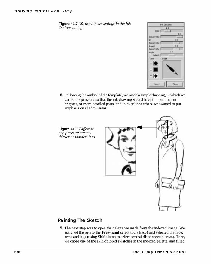
D r a w i n g Ta b l e t s A n d G i m p
e
t
. We,hen,
illed
8. Following the outline of the template, we made a simple drawing, in which wvaried the pressure so that the ink drawing would have thinner lines inbrighter, or more detailed parts, and thicker lines where we wanted to puemphasis on shadow areas.
Painting The Sketch9. The next step was to open the palette we made from the indexed image
assigned the pen to theFree-hand select tool (lasso) and selected the facearms and legs (using Shift+lasso to select several disconnected areas). Twe chose one of the skin-colored swatches in the indexed palette, and f
Figure 41.7 We used these settings in the InkOptions dialog
Figure 41.8 Differentpen pressure createsthicker or thinner lines
6 8 0 T h e G i m p U s e r ’ s M a n u a l

C h a p t e r 4 1
ueding,we
skin
like
the selected areas using theBucket Fill tool. The Fill tool was set toBehind mode, so that the contours would remain intact.
10. After applying the base color, we made a new transparent layer and continto draw using colors from the color palette. For the purpose of demonstratwe used a couple of different techniques. To build volume in the face area,switched to theBrush tool, where we used a large, soft brush with lowopacity. With the brush we painted soft shadows and color blend in the tone. For the arms and legs, we used theInk tool again. With short,determined strokes and a fine pencil tip, we worked to achieve a crayon-effect.
Figure 41.9 A solid skin tone was painted in thetransparent sketch layer using Behind mode
Figure 41.10 Soft blurry strokes or hard shortstrokes create very different artistic effects
T h e G i m p U s e r ’ s M a n u a l 6 8 1

D r a w i n g Ta b l e t s A n d G i m p
e
te theoto-
ed a
we
llowge.d
o
Making The Dress11. For the dress, purse and hair, we used some of the default patterns in th
Patternsdialog, and added a little 3-D effect by using a large, soft brushwith low opacity inOverlay or Multiply mode.
Drawing The BackgroundFor a background, we used a black-and-white photo of a busy street. To creadrawing, we used the same method that is described in “Transforming A Phgraph To A Drawing” on page 28.
12. We copied the scanned image into the white background layer, and placnew white layer on top of it. This layer was set toScreen mode, so that theblack paint strokes would be transparent.
13. We momentarily set the screen layer to half the normal opacity, so that could see the underlying image. The drawing was made with theInk tool,whereTilt andSpeed sensitivity were set to maximum values.
14. The sketch was made using many fast pen strokes, where we tried to fothe contours or the general direction of the dimensional planes in the imaThe combination of the two layers made the drawing much more detailewithout losing its sketch-like quality.
15. We also added someright-click|Filters|Blur| GaussianBlur andright-click|Filters|Distort| ValuePropagate to smooth out some of the roughness. The last touch was tadd some texture withright-click|Filters|Artistic|Canvas .
Figure 41.11 The Red Cubespattern was applied to the dress,Leather to the purse and Burlwood to
6 8 2 T h e G i m p U s e r ’ s M a n u a l

C h a p t e r 4 1
+ =
Figure 41.12 Drawing black lines in a Screen mode layerwill make the underlying image show through just enough toimprove the drawing without spoiling the illusion
T h e G i m p U s e r ’ s M a n u a l 6 8 3


P A R T
VIII Script-Fu• SCRIPT-FU
• MIKE’S BLACK BELT SCHOOL OF SCRIPT-FU


C H A P T E R
42 Script-Fu: Description And FunctionIn this chapter, we will take a look at what’s underthe Xtns/Script-Fu menu in the toolbox and the right-click menu.
S c r i p t - F u : D e s c r i p t i o n A n d F u n c t i o n
relled
se
witht-Fu,own97
n’talsouse
utble-
ourere
itg
en ayed.
ingthat
ssut,
SCRIPT-FU?Script-Fu is what the Windoze world would call a “macro.” But Script-Fu is mopowerful than that. Script-Fu is based on an interpreting language caScheme, and works by using querying functions to the Gimpdatabase. You cando all kinds of things with Script-Fu, but an ordinary Gimp user will probably uit for automating things that:
• He/she wants to do frequently.
• Are really complicated to do, and hard to remember.
Remember that you can do a whole lot with a Script-Fu. The scripts that comeGimp can be quite useful, but they can also serve as models for learning Scripor at least as a framework and source of modification when you make yourscript. Read “Mike Terry’s Black Belt School Of Script-Fu” starting on page 6if you want to learn how to make scripts.
We will describe some of the most useful scripts in this chapter, but we wocover them all. There are simply too many scripts. Some of the scripts arevery simple and you will probably not need any documentation to be able tothem.
Script-Fu (Scheme) isn’t the only scripting language available for Gimp. BScript-Fu is the only scripting language that is installed by default. Other availascripting extensions arePerl andTcl. You can download and install both extensions athttp://registry.gimp.org.
INSTALLING SCRIPT-FUS
The great thing about Script-Fus is that you can share your script with all yGimp friends. There are several scripts that come with Gimp by default, but thare also scripts that are available for download all around the Internet.
If you have downloaded a script, copy or move your new script to your.gimp/scripts directory and do arefresh.
The script will now appear in one of your menus. If you don’t find it, look forunder theroot file menu filters. If it doesn’t appear at all, something was wronwith the script.
Note that you can’t use more than one Script-Fu dialog at a time, so don’t opscript and one more after that. The last one will never be opened and displa
DO’S AND DON’TS
A common error when you are dealing with Script-Fus is that you simply brthem up and press the OK button. When nothing happens, you probably thinkthe script is broken or buggy, but there is most likely nothing wrong with it.
Think again. Did you really read the information in the dialog, or did you just prethe button? If you forgot an input the script needs, or if you gave it the wrong inpthe script will fail. One of the most common errors is that thefont specified in the
6 8 8 T h e G i m p U s e r ’ s M a n u a l

C h a p t e r 4 2
ation
stfol-
ite
rn
in the
di-
script dialog hasn’t been installed on your system. So please check the informin the dialog before blaming the script.
DIFFERENT KINDS OF SCRIPT-FUS
There are two kinds of Script-Fus —standalonescripts andimage-dependentscripts. You will find the standalone variants underXtns|Script-Fu| Type ofScript, and the image-dependent scripts are placed underright-click|Script-Fu| Type of Script.
STANDALONE SCRIPTS
We will not try to describe every script in depth, as we did with the filters. MoScript-Fus are very easy to understand and use. At the time of this writing, thelowing types are installed by default:
• Patterns
• Web page themes
• Logos
• Buttons
• Utils
• Make Brush
• Misc.
PatternsYou will find all kinds of pattern-generating scripts here. Generally, they are quuseful because you can add many arguments to your own patterns.
We’ll take a look at theLand script. In this script you have to set the image/pattesize, and specify what levels ofrandomto use for your land creation. The colorsused to generate the land map are taken from the currently selected gradientgradient editor. You must also supply values for the level ofdetail, land and seaheight/depthand thescale. Scale refers to the scale of your map, just as in an ornary road map, 1:10 will be typed as 10.
Figure 42.1 The Land script
T h e G i m p U s e r ’ s M a n u a l 6 8 9

S c r i p t - F u : D e s c r i p t i o n A n d F u n c t i o n
tommee to
outhat
age
ithcript.dia-
r
Web Page ThemesHere is clearly a practical use for scripts. By creating a script for making custext, logos, buttons arrows, etc., for your web site, you will give them all the sastyle and shape. You will also be saving a lot of time, because you don’t havcreate every logo, text or button by hand.
You will find the Gimp.org theme under the Web page theme submenu. If ywant to create your own theme, this script will serve as an excellent templateyou can modify to create a theme for your web site.
Most of the scripts are quite self-explanatory, but here are some hints:
• Leave all strange characters like’ and” intact.
• Make sure that the pattern specified in the script exists.
• Padding refers to the amount of space around your text.
• A high value for bevel width gives the illusion of ahigher button.
• If you typeTRUE for “Press”, the button will look pushed down.
• Choosetransparency if you don’t want a solid background. If youchoose a solid background, make sure it is the same color as the web pbackground.
LOGOS
Here you will find all kinds of logo-generating scrips. This is nice, but use it wcare, as people might recognize your logo as being made by a known Gimp sYou should rather regard it as a base that you can modify to fit your needs. Thelog for making a logo is more or less the same for all such scripts:
1. In theText String field, type your logo name, likeFrozenriver.
2. In theFont Sizetext field, type the size of your logo in pixels.
3. In theFont text field, type the name of the font that you want to use for youlogo.
4. To choose the color of your logo, just click on thecolor button. This bringsup a color dialog.
5. If you look at the currentcommand field, you can watch the script run.
Figure 42.2 Have you ever seenthis logo before :-) When the Gimpfolks createdwww.gimp.org , theymade things a bit easier by creatingscripts for text, logos, buttons andheadings.
6 9 0 T h e G i m p U s e r ’ s M a n u a l

C h a p t e r 4 2
hasripts..
you
inent
e
f you
Make ButtonsUnder this headline you’ll find a script that makes beveled buttons. The scripta dozen parameters or so, and most of them are similar to those in the logo scYou can experiment with different settings to come up with a button you like
UtilsUnder Utils you will find a small but nice script: theFontmap script, whichmakes an image of your fonts. You will have to type the names of the fontswant displayed in theFonts text field. A tip is to usexfontsel to see what fontsare installed (see “How To Get Fonts To Gimp” starting on page 759).
TheCustom gradient script creates an image of the current custom gradientthe gradient editor. This can be useful if you want to pick colors from a gradias in a palette.
Misc.UnderMisc. you’ll find scripts that can be quite useful, but aren’t suitable for thother submenus. An example is theSpherescript. You will have to set theradiusin pixels to determine the sphere size. Thelighting angle is where at the sphereyou point the spotlight. This value also has an impact on the sphere shadow. Idon’t want a shadow, you will have to typeFALSE. The last thing you have toselect is background color, and the color of your sphere.
Figure 42.3 Gimp has a largecollection of logo scripts, but youshould be aware that a lot of peoplemay recognize your web page logo asgenerated by a script and not by you
Figure 42.4 A Gimp Script-Fu generated 3-D sphere
T h e G i m p U s e r ’ s M a n u a l 6 9 1

S c r i p t - F u : D e s c r i p t i o n A n d F u n c t i o n
h or, youageec-wly
tingtime
Make BrushThis script lets you make your own custom rectangular/circular brushes, witwithout feathered (blurred) edges. To ensure full control over the parameterswill have to look in “Brushes, Gradients, Palettes And Patterns” starting on p171. The script will automatically store your brush in your personal brush dirtory. You just have to press refresh in the Brush Selection dialog to use your necreated brush.
IMAGE-DEPENDENT SCRIPTS
The image-dependent script is a script that will perform operations on an exisimage. These scripts are more like the plug-ins in the Filters submenu. At theof this writing, the following script groups are installed by default:
• Decor
• Modify
• Animators
• Stencil Ops
• Alchemy
• Shadow
• Render
• Utils
• Selection
STENCIL OPS
Here, you’ll find two scripts:Carve-ItandChrome-It, which can render some trulynice artistic effects on grayscale images.
Figure 42.5 Carve-It and Chrome-It are popular special-effectCarve-It Chrome-It
6 9 2 T h e G i m p U s e r ’ s M a n u a l

C h a p t e r 4 2
theras-uch
. Thethe
ing
ge,ask
haspage
adet
ALCHEMY
Unsharp MaskOne of the most useful Script-Fus isUnsharp Mask, which sharpensan unfo-cused or blurred image. Unsharp Mask is often a better alternative thanright-click|Filters|Enhance| Sharpen .
Sharpen will accentuate all of your image, including scratches, noise and oimperfections that you don’t want in your image. Unsharp Mask works by increing the contrast of edges and nearby pixels, while leaving other areas pretty muntouched. This makes Unsharp Mask ideal for enhancing scanned imagesmask valuecontrols the amount of sharpening, or more accurately, how wideedge areas should be.
If you apply image-effect functions like Scale, Rotate and Perspective, try usUnsharp Mask afterward, as those types of filters useinterpolationand therebysoften or blur your image. If you just want to enhance a small part of your imathen the ordinary Sharpen filter is an adequate tool (you can’t use Unsharp Mon selections).
Note: There is now also an Unsharp Mask plug-in available (not a script) thatthe same functionality, but has even better precision; see “Unsharp Mask” on498.
Tip: It’s a good idea to run Unsharp Mask twice, with half the mask value insteof just once with the whole value. This will sharpen more smoothly (don’t forgto flatten the image).
Figure 42.6 Unsharp mask is avery useful image-enhancing tool
Before Unsharp Mask After Unsharp Mask
T h e G i m p U s e r ’ s M a n u a l 6 9 3
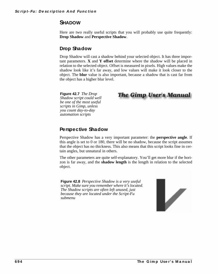
S c r i p t - F u : D e s c r i p t i o n A n d F u n c t i o n
tly:
por-ne theeom
umescer-
ori-
SHADOW
Here are two really useful scripts that you will probably use quite frequenDrop Shadow andPerspective Shadow.
Drop ShadowDrop Shadow will cast a shadow behind your selected object. It has three imtant parameters.X andY offset determine where the shadow will be placed irelation to the selected object. Offset is measured in pixels. High values makshadow look like it’s far away, and low values will make it look closer to thobject. Theblur value is also important, because a shadow that is cast far frthe object has a higher blur level.
Perspective ShadowPerspective Shadow has a very important parameter: theperspective angle. Ifthis angle is set to 0 or 180, there will be no shadow, because the script assthat the object has no thickness. This also means that this script looks fine intain angles, but unnatural in others.
The other parameters are quite self-explanatory. You’ll get more blur if the hzon is far away, and theshadow lengthis the length in relation to the selectedobject.
Figure 42.7 The DropShadow script could wellbe one of the most usefulscripts in Gimp, unlessyou count day-to-dayautomation scripts
Figure 42.8 Perspective Shadow is a very usefulscript. Make sure you remember where it’s located.The Shadow scripts are often left unused, justbecause they are located under the Script-Fusubmenu
6 9 4 T h e G i m p U s e r ’ s M a n u a l


C H A P T E R
43 Mike Terry’s Black Belt School Of Script-FuAuthor Mike Terry

M i ke Te r r y ’ s B l a ck B e l t S c h o o l O f S c r i p t - F u
ts?
re, orript
elt
tool-age
ch,new
ngtips
r of
eardor-noofthe.
re, Im-
THE ROAD TO SCRIPT-FU MASTERY
So, little grasshopper, you have found Gimp, and you want to learn of its secre
More specifically, you wish to learn of its fantastic scripting abilities, no? You aperhaps tantalized at the prospect of automating image-editing drudgerymaybe you seek the kind of precision in your work that only a well-written sccan achieve....
Well, you have come to the right place, my friend, as Mike Terry’s Black BSchool of Script-Fu can train you in the not-so-ancient art of Script-Fu.
COURSE OUTLINE
In this training course, we’ll introduce you to the fundamentals ofSchemenec-essary to use Script-Fu, and then build a handy script that you can add to yourbox of scripts. The script prompts the user for some text, then creates a new imsized perfectly to the text. We will then enhance the script to allow for abufferofspace around the text.
Meet Your InstructorLet me first confess that I am currently only a yellow-belt of this art, and as sucan only take you so far. However, together, we can press on and reachheights. If I err, omit some important detail in this training or am just plain wroabout something, please email me so I may correct it. Similarly, if you haveor suggestions on how to improve your training, please forward them to me.
I hope you benefit from this training, and may you soon become a MasteScript-Fu!
AudienceThese training sessions are intended for the beginning Script-Fu’er. When I hthat Gimp was scriptable, I got very excited, and wanted to dive right in. Unftunately, the tutorials were scant and incomplete, especially if you knewScheme (like I didn’t). After about two days of trying to force my square pegC/C++ knowledge into the round hole of Scheme, I reckoned a tutorial fromground-up, chock-full of demos, would do the new Script-Fu’er a lot of good
Currently, then, the tutorial is really aimed at the beginner, but as I learn mowill expand it so we can all be Script-Fu Masters! Your suggestions and coplaints are welcome:
Michael Terry
6 9 8 T h e G i m p U s e r ’ s M a n u a l

C h a p t e r 4 3
t is,of
to
,
nto
pt-
ted
you
:
LESSON 1: GETTING ACQUAINTED WITH SCHEME
BEFORE WE BEGIN...
Before we begin, we have to make sure we’re all at the same training hall. Thayou must have Gimp installed and fully functional. To get the latest versionGimp, or for pointers on installing it and getting it running, we refer youGimp’s central home page. (This tutorial was written using Gimp 1.0.0.)
LET’S START SCHEME’ING
The first thing to learn is that:
• Every statement in Scheme is surrounded by parentheses ().
The second thing you need to know is that:
• The function name/operator is always the first item in the parenthesesand the rest of the items are parameters to the function.
However, not everything enclosed in parentheses is a function — they caalso be items in a list — but we’ll get to that later. This notation is referredasprefix notation, because the function prefixes everything else. If you’refamiliar with postfix notation, or own a calculator that usesReverse PolishNotation (such as most HP calculators), you should have no problem adaing to formulating expressions in Scheme.
The third thing to understand is that:
• Mathematical operators are also considered functions, and thus are lisfirst when writing mathematical expressions.
This follows logically from the prefix notation that we just mentioned.
Examples Of Prefix, Infix, And Postfix NotationsHere are some quick examples illustrating the differences betweenprefix, infix,andpostfix notations. We’ll add a 1 and 3 together:
• Prefix notation: + 1 3 (the way Scheme will want it)
• Infix notation: 1 + 3 (the way we “normally” write it)
• Postfix notation: 1 3 + (the way many HP calculators will want it)
PRACTICING IN SCHEME
Now, grasshopper, let’s practice what we have just learned. Start up Gimp, ifhave not already done so, and chooseXtns/Script-Fu/ Console . Thiswill start up theScript-Fu Consolewindow, which allows us to work interac-tively in Scheme. In a matter of moments, the Script-Fu Console will appear
T h e G i m p U s e r ’ s M a n u a l 6 9 9

M i ke Te r r y ’ s B l a ck B e l t S c h o o l O f S c r i p t - F u
asy,
ately
r yououit. In
y.er:
be
THE SCRIPT-FU CONSOLE WINDOW
At the bottom of this window is an entry-field entitledCurrent Command.Here, we can test out simple Scheme commands interactively. Let’s start out eand add some numbers:
(+ 3 5)
Typing this in and hitting Return yields the expected answer of8 in the center win-dow.
Now, what if we wanted to add more than one number? The “+” function can taketwo or more arguments, so this is not a problem:
(+ 3 5 6)
This also yields the expected answer of14 .
So far, so good — we type in a Scheme statement and it’s executed immediin the Script-Fu Console window. Now for a word of caution....
WATCH OUT FOR EXTRA PARENS
If you’re like me, you’re used to being able to use extra parentheses whenevewant to — like when you’re typing a complex mathematical equation and ywant to separate the parts by parentheses to make it clearer when you readScheme, you have to be careful andnot insertthese extra parentheses incorrectlFor example, say we wanted to add 3 to the result of adding 5 and 6 togeth
3 + (5 + 6) + 7= ?
Knowing that the + operator can take a list of numbers to add, you mighttempted to convert the above to the following:
Figure 43.1 Startingup the Script-Fuconsole
Figure 43.2 The Script-Fu console
7 0 0
T h e G i m p U s e r ’ s M a n u a l
C h a p t e r 4 3
andll aose
va,rop-
me isr anythe
ntil
ns?
pre-
andd b,
(+ 3 (5 6) 7)
However, this is incorrect — remember, every statement in Scheme startsends with parens, so the Scheme interpreter will think that you’re trying to cafunction named “5” in the second group of parens, rather than summing thnumbers before adding them to 3.
The correct way to write the above statement would be:
(+ 3 (+ 5 6) 7)
MAKE SURE YOU HAVE THE PROPER SPACING, TOO
If you are familiar with other programming languages, like C/C++, Perl or Jayou know that you don’t need white space around mathematical operators to perly form an expression:
3+5, 3 +5, 3+ 5
These are all accepted by C/C++, Perl and Java compilers. However, the sanot true for Scheme. You must have a space after a mathematical operator (oother function name or operator) in Scheme for it to be correctly interpreted byScheme interpreter.
Practice a bit with simple mathematical equations in the Script-Fu Console uyou’re totally comfortable with these initial concepts.
LESSON 2: OF VARIABLES AND FUNCTIONS
So, my student, you are curious and want to know about variables and functioSuch vigor in your training — I like it.
VARIABLES
Now that we know that every Scheme statement is enclosed inparentheses, andthat the function name/operator islisted first, we need to know how to create andusevariables, and how to create and usefunctions. We’ll start with the vari-ables.
Declaring VariablesAlthough there are a couple of different methods for declaring variables, theferred method is to use thelet* construct. If you’re familiar with other program-ming languages, this construct is equivalent to defining a list of local variablesa scope in which they’re active. As an example, to declare two variables, a aninitialized to 1 and 2, respectively, you’d write:
T h e G i m p U s e r ’ s M a n u a l 7 0 1

M i ke Te r r y ’ s B l a ck B e l t S c h o o l O f S c r i p t - F u
.elption
f
e
valid
e only
notdipt.rclos-win-
or, as one line:
(let* ( (a 1) (b 2) ) (+ a b) )
Note: You’ll have to put all of this on one line if you’re using the console windowIn general, however, you’ll want to adopt a similar practice of indentation to hmake your scripts more readable. We’ll talk a bit more about this in the sec“White Space” on page 702.
This declares two local variables,a andb, initializes them, then prints the sum othe two variables.
What Is A Local Variable?You’ll notice that we wrote the summation (+ a b ) within the parens of thelet* expression, not after it.
This is because thelet* statement defines an area in your script in which thdeclared variables are usable; if you type the (+ a b ) statement after the (let*... ) statement, you’ll get an error, because the declared variables are onlywithin the context of thelet* statement; they are what programmers calllocalvariables.
The General Syntax Of let*The general form of alet* statement is:
(let* ( variables ) expressions )
wherevariables are declared within parens, e.g., (a 2), andexpressionsareany valid Scheme expressions. Remember that the variables declared here arvalid within thelet* statement — they’relocal variables.
White SpacePreviously, we mentioned the fact that you’ll probably want to useindentationto help clarify and organize your scripts. This is a good policy to adopt, and isa problem in Scheme —white spaceis ignored by the Scheme interpreter, ancan thus be liberally applied to help clarify and organize the code within a scrHowever, if you’re working in Script-Fu’s Console window, you’ll have to entean entire expression on one line; that is, everything between the opening anding parens of an expression must come on one line in the Script-Fu Consoledow.
(let* ((a 1)(b 2)
)(+ a b)
)
7 0 2 T h e G i m p U s e r ’ s M a n u a l

C h a p t e r 4 3
n in
the
ur
cal,tion
n’tuage.
n
wege?
Assigning A New Value To A VariableOnce you’ve initialized a variable, you might need to change its value later othe script. Use theset! statement to change the variable’s value:
(let* ( (theNum 10) ) (set! theNum (+ theNum \theNum)) )
Try to guess what the above statement will do, then go ahead and enter it inScript-Fu Console window.
Note: The “\” indicates that there is no line break. Ignore it (don’t type it in yoScript-Fu console and don’t hit Enter), just continue with the next line.
FUNCTIONS
Now that you’ve got the hang of variables, let’s get to work with somefunctions.You declare a function with the following syntax:
(define (name param-list) expressions )
wherename is the name assigned to this function,param-list is a space-delimited list of parameter names, and expressions is a series ofexpressionsthatthe function executes when it’s called. For example:
(define (AddXY inX inY) (+ inX inY) )
AddXY is the function’s name andinX and inY are the variables. This func-tion takes its two parameters and adds them together.
If you’ve programmed in other imperative languages (like C/C++, Java, Pasetc.), you might notice that a couple of things are absent in this function definiwhen compared to other programming languages.
• First, notice that the parameters don’t have any “types” (that is, we diddeclare them as strings, or integers, etc.). Scheme is a type-less langThis is handy and allows for quicker script writing.
• Second, notice that we don’t need to worry about how to “return” theresult of our function — the last statement is the value “returned” whecalling this function. Type the function into the console, then trysomething like:
(AddXY (AddXY 5 6) 4)
LESSON 3: LISTS, LISTS AND MORE LISTS
We’ve trained you in variables and functions, young Script-Fu’er, and nowmust enter the murky swamps of Scheme’s lists. Are you ready for the challen
T h e G i m p U s e r ’ s M a n u a l 7 0 3

M i ke Te r r y ’ s B l a ck B e l t S c h o o l O f S c r i p t - F u
nce
ousvari-
sign
ies.
ng
r
DEFINING A LIST
Before we talk more about lists, it is necessary that you know the differebetweenatomic values andlists.
You’ve already seen atomic values when we initialized variables in the previlesson. An atomic value is a single value. So, for example, we can assign theable “x” the single value of 8 in the following statement:
(let* ( (x 8) ) x)
(We added the expressionx at the end to print out the value assigned tox—normally you won’t need to do this. Notice howlet* operates just like a func-tion: The value of the last statement is the value returned.)
A variable may also refer to a list of values, rather than a single value. To asthe variablex the list of values1, 3, 5, we’d type:
(let* ( (x ’(1 3 5))) x)
Try typing both statements into the Script-Fu Console and notice how it replWhen you type the first statement in, it simply replies with the result:
8
However, when you type in the other statement, it replies with the followiresult:
(1 3 5)
When it replies with the value8 it is informing you thatx contains the atomicvalue 8. However, when it replies with (1 3 5 ), it is then informing you thatxcontains not a single value, but a list of values. Notice that there are nocommasinour declaration or assignment of the list, nor in the printed result.
The syntax to define a list is:
’(a b c)
wherea, b, andc areliterals. We use theapostrophe(’ ) to indicate that whatfollows in the parentheses is alist of literal values, rather than a function oexpression.
An empty list can be defined as such:
’()
or simply:
()
7 0 4 T h e G i m p U s e r ’ s M a n u a l

C h a p t e r 4 3
ophet-Fu
es;
nt
tion,) and
uld
the
Lists can contain atomic values, as well as other lists:
Notice that after the first apostrophe, you no longer need to use an apostrwhen defining the inner lists. Go ahead and copy the statement into the ScripConsole and see what it returns.
You should notice that the result returned is not a list of single, atomic valurather, it is a list of a literal (“The Gimp ”), the list (1 2 3 ), etc.
HOW TO THINK OF LISTS
It’s useful to think of lists as composed of a “head” and a “tail .” The head is thefirst element of the list, the tail the rest of the list. You’ll see why this is importawhen we discuss how to add to lists and how to access elements in the list.
Creating Lists Through Concatenation(The Cons Function)One of the more common functions you’ll encounter is thecons function. It takesa value and prepends it to its second argument, a list. From the previous secI suggested that you think of a list as being composed of an element (the headthe remainder of the list (the tail). This is exactly howcons functions — it addsan element to the head of a list. Thus, you could create a list as follows:
(cons 1 ’(2 3 4) )
The result is the list (1 2 3 4 ).
You could also create a list with one element:
(cons 1 () )
You can use previously declared variables in place of any literals, as you woexpect.
Defining A List Using The list FunctionTo define a list composed of literals or previously declared variables, uselist function:
(let*
(
(x ’("The Gimp" (1 2 3) ("is" \("great" ()) ) ) )
)
x
)
T h e G i m p U s e r ’ s M a n u a l 7 0 5

M i ke Te r r y ’ s B l a ck B e l t S c h o o l O f S c r i p t - F u
s
eak
be
re
(list 5 4 3 a b c)
This will compose and return a list containing the values held by the variablea,b andc . For example:
This code creates the list(5 4 3 1 2 3 ).
ACCESSING VALUES IN A LIST
To access the values in a list, use the functionscar andcdr , which return thefirst element of the list and the rest of the list, respectively. These functions brthe list down into the head::tail construct I mentioned earlier.
The car Functioncar returns the first element of the list (the head of the list). The list needs tonon-null. Thus, the following returns the first element of the list:
(car ’("first" 2 "third"))
which is:
"first"
The cdr functioncdr returns the rest of the list after the first element (the tail of the list). If theis only one element in the list, it returns an empty list.
(cdr ’("first" 2 "third"))
returns:
(2 "third")
whereas the following:
(cdr ’("one and only"))
returns:
()
(let* (
(a 1)
(b 2)
(c 3)
)
(list 5 4 3 a b c)
)
7 0 6 T h e G i m p U s e r ’ s M a n u a l

C h a p t e r 4 3
butveralil of
d tails
l-
ng
do
ACCESSING OTHER ELEMENTS IN A LIST
OK, great, we can get the first element in a list, as well as the rest of the list,how do we access the second, third or other elements of a list? There exist se“convenience” functions to access, for example, the head of the head of the taa list (caadr ), the tail of the tail of a list (cddr ), etc.
The basic naming convention is easy: The a’s and d’s represent the heads anof lists, so
(car (cdr (car x) ) )
could be written as:
(cadar x)
To view a full list of the list functions, refer to Appendix C, which lists the avaiable functions for the version of Scheme used by Script-Fu.
To get some practice with list-accessing functions, try typing in the followi(except all on one line if you’re using the console); use different variations ofcarandcdr to access the different elements of the list:
Try accessing the number 3 in the list using only two function calls. If you canthat, you’re on your way to becoming a Script-Fu Master!
(let*
(
(x ’ (
(1 2 (3 4 5) 6)
7 8
(9 10)
)
)
)
; place your car/cdr code here
)
T h e G i m p U s e r ’ s M a n u a l 7 0 7

M i ke Te r r y ’ s B l a ck B e l t S c h o o l O f S c r i p t - F u
en,
ithow
ch
as-
ser
’re
s tore-rate
ld
e
LESSON 4: YOUR FIRST SCRIPT-FU SCRIPT
Do you not need to stop and catch your breath, little grasshopper? No? Well thlet’s proceed with your fourth lesson — your first Script-Fu Script.
CREATING A TEXT BOX SCRIPT
One of the most common operations I perform in Gimp is creating a box wsome text in it for a web page, a logo or whatever. However, you never quite knhow big to make the initial image when you start out. You don’t know how muspace the text will fill with the font and font size you want.
The Script-Fu Master (and student) will quickly realize that this problem can eily be solved and automated with Script-Fu.
We will, therefore, create a script, calledText Box, which creates an image cor-rectly sized to fit snugly around a line of text the user inputs. We’ll also let the uchoose thefont, font size andtext color.
GETTING STARTED
Editing And Storing Your ScriptsUp until now, we’ve been working in the Script-Fu Console. Now, however, wegoing to switch to editingscript text files.
Where you place your scripts is a matter of preference — if you have accesGimp’s default script directory, you can place your scripts there. However, I pfer keeping my personal scripts in my own script directory, to keep them sepafrom the factory-installedscripts.
In the .gimp directory that Gimp made off of your home directory, you shoufind a directory calledscripts . Gimp will automatically look in your.gimpdirectory for ascripts directory, and add the scripts in this directory to thScript-Fu database. You should place your personal scripts here.
The Bare EssentialsEvery Script-Fu script defines at least onefunction, which is the script’s mainfunction. This is where you do the work.
Every script must alsoregisterwith theprocedural database, so you can accessit within Gimp.
We’ll define the main function first:
(define (script-fu-text-box inText inFont inFontSizeinTextColor))
Here, we’ve defined a new function calledscript-fu-text-box thattakes four parameters, which will later correspond to some text, afont, the font
7 0 8 T h e G i m p U s e r ’ s M a n u a l

C h a p t e r 4 3
g.
ens,mam-
e the
uph
n-thisd,
in
size, and the text’scolor. The function is currently empty and thus does nothinSo far, so good — nothing new, nothing fancy.
Naming ConventionsScheme’s naming conventions seem to prefer lowercase letters with hyphwhich I’ve followed in the naming of the function. However, I’ve departed frothe convention with the parameters. I like more descriptive names for my pareters and variables, and thus add the “in ” prefix to the parameters so I can quicklysee that they’re values passed into the script, rather than created within it. I usprefix “the ” for variables defined within the script.
It’s Gimp convention to name your script functionsscript-fu-abc ,because then when they’re listed in the procedural database, they’ll all showunderscript-fu when you’re listing the functions. This also helps distinguisthem from plug-ins.
Registering The FunctionNow, let’s register the function with Gimp. This is done by calling the functioscript-fu-register . When Gimp reads in a script, it will execute this function, which registers the script with the procedural database. You can placefunction call wherever you wish in your script, but I usually place it at the enafter all my other code.
Here’s the listing for registering this function (I will explain all its parametersa minute):
(script-fu-register
”script-fu-text-box” ;func name
”<Toolbox>/Xtns/Script-Fu/Text/Text Box”;menu pos
”Creates a simple text box, sized to fit around the user’s \ choice of text,font, font size, and color.”
”Michael Terry” ;author
”copyright 1997, Michael Terry” ;copyright notice
”October 27, 1997” ;date created
”” ;Image type that the script works on
SF-VALUE ”Text:” ”\”Text Box\””;a text variable
SF-VALUE ”Font:” ”\”Charter\””;a text variable
SF-VALUE ”Font size:” ”45” ;a text variable
SF-COLOR ”Color:” ’(0 0 0) ;color variable
)
T h e G i m p U s e r ’ s M a n u a l 7 0 9

M i ke Te r r y ’ s B l a ck B e l t S c h o o l O f S c r i p t - F u
hehat
e.
If you save these functions in a text file with a.scm suffix in your script direc-tory, then chooseXtns|Script-Fu| Refresh , this new script will appearasXtns|Script-Fu|Text|Text Box .
If you invoke this new script, it won’t do anything, of course, but you can view tprompts you created when registering the script (more information about wwe did is covered next).
Finally, if you invoke theDB Browser (the procedural database browser —Xtns|DB Browser ), you’ll notice that our script now appears in the databas
Figure 43.3 The new script willappear in the menu after you haverefreshed your Script-Fu directory
Figure 43.4 The new scriptdialog
Figure 43.5 The DB Browser
7 1 0 T h e G i m p U s e r ’ s M a n u a l
C h a p t e r 4 3
long
we
e
hee reg-
.
n’t
eterss, we
the
Steps For Registering The ScriptTo register our script with Gimp, we call the functionscript-fu-register ,fill in the seven required parameters and add our script’s own parameters, awith a description and default value for each parameter.
The Required Parameters
• Thename of the function we defined. This is the function called whenour script is invoked (the entry-point into our script). This is necessarybecause we may define additional functions within the same file, andGimp needs to know which of these functions to call. In our example, only defined one function,text-box , which we registered.
• The location in the menu where the script will be inserted. The exactlocation of the script is specified like a path in Unix, with the root of thpath being eithertoolbox or right-clic k.
If your script does not operate on an existing image (and thus creates anewimage, like our Text Box script will), you’ll want to insert it in thetoolboxmenu — this is the menu in Gimp’s main window (where all the tools arelocated: the selection tools, magnifying glass, etc.).
If your script is intended to work on an image beingedited, you’ll want toinsert it in the menu that appears when you right-click on an open image. Trest of the path points to the menu lists, menus and sub-menus. Thus, wistered our Text Box script in the Text menu of the Script-Fu menu of theXtns menu of the toolbox (Xtns|Script-Fu|Text|Text Box ).
If you notice, theText sub-menu in theScript-Fu menu wasn’t there whenwe began — Gimp automatically creates any menus not already existing
• A description of your script. I’m not quite sure where this is displayed.
• Your name (the author of the script).
• Copyright information.
• Thedate the script was made, or the lastrevision of the script.
• Thetypes of images the script works on. This may be any of thefollowing: RGB, RGBA, GRAY, GRAYA, INDEXED, INDEXEDA. Or itmay be none at all — in our case, we’re creating an image, and thus doneed to define the type of image on which we work.
Registering The Script’s ParametersOnce we have listed the required parameters, we then need to list the paramthat correspond to the parameters our script needs. When we list these paramgivehintsas to what their types are. This is for the dialog which pops up whenuser selects our script. We also provide adefault value.
This section of the registration process has the following format:
Param-type ”Prompt text” ”default value”
T h e G i m p U s e r ’ s M a n u a l 7 1 1

M i ke Te r r y ’ s B l a ck B e l t S c h o o l O f S c r i p t - F u
The different parameter types, plus examples, are listed inTable 43.1.
Now, young student, this was a lot of information, so take a break.
Table 43.1 Parameter list
Param Type Description Examples
SF-VALUE Accepts numbers and strings.Note that quotes must beescaped for default text.
SF-VALUE “Text:” “\“Some text\””
SF-VALUE “A number:” “34”
SF-COLOR Indicates that a color isrequested in this parameter.
SF-COLOR “Color:” ’(0 0 0)
SF-TOGGLE A checkbox is displayed, toget boolean value.
SF-TOGGLE “Resize?” TRUE
SF-IMAGE If your script operates on anopen image, this should be thefirst parameter after therequired parameters. Gimpwill pass in a reference to theimage in this parameter.
SF-IMAGE “The image” 0
SF-DRAWABLE If your script operates on anopen image, this should be thesecond parameter after the SF-IMAGE param. It refers to theactive layer. Gimp will pass ina reference to the active layerin this parameter.
SF-DRAWABLE “The layer” 0
7 1 2 T h e G i m p U s e r ’ s M a n u a l

C h a p t e r 4 3
with
imp.
ctly.
heions
lland
LESSON 5: GIVING OUR SCRIPT SOME GUTS
You show great dedication to your studies, my student. Let us thus continueyour training and add some functionality to our script.
CREATING A NEW IMAGE
In the previous lesson, we created an empty function and registered it with GIn this lesson, we want to providefunctionalityto our script — we want to createa new image, add the user’s text to it and resize the image to fit the text exa
Once you know how to setvariables, define functions and accesslist mem-bers, the rest is all downhill — all you need to do is familiarize yourself with tfunctions available in Gimp’s procedural database and call those functdirectly. So fire up the DB Browser and let’s get cookin’!
Let’s begin by making a new image. We’ll create a new variable,theImage ,set to the result of calling Gimp’s built-in functiongimp-image-new .
As you can see from theDB Browser, the functiongimp-image-new takesthree parameters — the image’swidth , height and thetype of image. Becausewe’ll later resizethe image to fit the text, we’ll make a 10x10 RGB image. We’store the image’s width and sizes in some variables, too, as we’ll refer tomanipulate them later in the script.
Figure 43.6 The DB Browser
T h e G i m p U s e r ’ s M a n u a l 7 1 3

M i ke Te r r y ’ s B l a ck B e l t S c h o o l O f S c r i p t - F u
ld
y onernf the
sthee’veark-
his
Note: We used the valueRGBto specify that the image is an RGB image. We couhave also used0, butRGB is more descriptive when we glance at the code.
You should also notice that we took theheadof the result of the function call. Thismay seem strange, because the database explicitly tells us that it returns onlvalue — the ID of the newly created image. However, all Gimp functions retua list, even if there is only one element in the list, so we need to get the head olist.
Adding A New Layer To The ImageNow that we have an image, we need to add a layer to it. We’ll call thegimp-layer-new function to create the layer, passing in the ID of the image we jucreated. (From now on, instead of listing the complete function, we’ll only list tlines we’re adding to it. You can see the complete script here.) Because wdeclared all of the local variables we’ll use, we’ll also close the parentheses ming the end of our variable declarations:
Once we have the new layer, we need to add it to the image:
(gimp-image-add-layer theImage theLayer 0)
Now, just for fun, let’s see the fruits of our labors up until this point, and add tline to show the new, empty image:
(gimp-display-new theImage)
(define (script-fu-text-box inText inFont inFontSize inTextColor)
(let*
(
; define our local variables
; create a new image:
(theImageWidth 10)
(theImageHeight 10)
(theImage (car (gimp-image-new theImageWidth theImageHeight RGB) )
; theText is a declaration for the text we create later
(theText)
; create a new layer for the image:
(theLayer (car (gimp-layer-new theImage theImageWidth \theImageHeight RGB_IMAGE “layer 1” 100 NORMAL) ))
; end of our local variables
7 1 4 T h e G i m p U s e r ’ s M a n u a l

C h a p t e r 4 3
rs),
the
the
-re
can, the
Save your work, selectXtns/Script-Fu/ Refresh , run the script and anew image should pop up. It will probably contain garbage (random colobecause we haven’t erased it. We’ll get to that in a second.
Adding The TextGo ahead andremove the line to display the image (or comment it out with a;as the first character of the line).
Before we add text to the image, we need to set thebackground and fore-ground colors so that the text appears in the color the user specified. We’ll usegimp-palette-set-back/foreground functions:
(gimp-palette-set-background ’(255 255 255) )
(gimp-palette-set-foreground inTextColor)
With the colors properly set, let’s now clean out the garbage currently inimage. We’ll select everything in the image, and callclear:
(gimp-selection-all theImage)
(gimp-edit-clear theImage theLayer)
(gimp-selection-none theImage)
With the image cleared, we’re ready to add sometext:
Although a long function call, it’s fairly straightforward if you go over the parameters while looking at the function’s entry in the DB Browser. Basically, we’creating a new text layer and assigning it to the variabletheText .
Now that we have the text, we can grab itswidth andheight and resize the imageand the image’s layer to the text’s size:
If you’re like me, you’re probably wondering what adrawable is when comparedto a layer. The difference between the two is that a drawable is anything thatbe drawn into; a layer is a more specific version of a drawable. In most casesdistinction is not important.
(set! theText (car (gimp-text theImage theLayer 0 0 inText 0 \TRUE inFontSize PIXELS ”*” inFont ”*” ”*” ”*” ”*”)))
(set! theImageWidth (car (gimp-drawable-width theText) ) )
(set! theImageHeight (car (gimp-drawable-height theText) ) )
(gimp-image-resize theImage theImageWidth theImageHeight 0 0)
(gimp-layer-resize theLayer theImageWidth theImageHeight 0 0)
T h e G i m p U s e r ’ s M a n u a l 7 1 5

M i ke Te r r y ’ s B l a ck B e l t S c h o o l O f S c r i p t - F u
ould
useceingple
thatipt isnt
inue
the
emanip-
func-are
With the image ready to go, we can now re-add our display line:
(gimp-display-new theImage)
Save your work, refresh the database and give your first script a run! You shget something like Figure 43.7.
Clearing The Dirty FlagIf you try to close the image created without firstsaving the file, Gimp will askyou if you want to save your work before you close the image. It asks this becathe image is marked asdirty, or unsaved. In the case of our script, this is a nuisanfor the times when we simply give it a test run and don’t add or change anythin the resulting image — that is, our work is easily reproducible in such a simscript, so it makes sense to get rid of thisdirty flag.
To do this, we can clear the dirty flag after displaying the image:
(gimp-image-clean-all theImage)
This will dirty count to 0, making it appear to be a “clean” image.
Whether to add this line or not is a matter of personal taste. I use it in scriptsproduce new images, where the results are trivial, as in this case. If your scrvery complicated, or if it works on an existing image, you will probably not wato use this function.
LESSON 6: EXTENDING THE TEXT BOX SCRIPT
Your will and determination are unstoppable, my eager student. So let us contyour training.
HANDLING UNDO CORRECTLY
When creating a script, you want to give your users the ability toundo theiractions, should they make a mistake. This is easily accomplished by callingfunctions gimp-undo-push-group-start and gimp-undo-push-group-end around the code that manipulates the image. You can think of thas matched statements that let Gimp know when to start and stop recording mulations on the image, so that those manipulations can later be undone.
If you are creating a new image entirely, it doesn’t make sense to use thesetions because you’re not changing an existing image. However, when youchanging an existing image, you most surely want to use these functions.
Figure 43.7 Our text box
7 1 6 T h e G i m p U s e r ’ s M a n u a l

C h a p t e r 4 3
nc-andesn’t
fea-
no
d ato
t’sn
tion
As of this writing, undoing a script works nearly flawlessly when using these futions. However, it does seem to have some trouble undoing everything, nowthen, and it seems to have the hardest time when calling another script that doitself call these functions.
EXTENDING THE SCRIPT A LITTLE MORE
Now that we have a very handy-dandy script to create text boxes, let’s add twotures to it:
• Currently, the image is resized to fit exactly around the text — there’s room for anything, like drop shadows or special effects (even thoughmany scripts will automatically resize the image as necessary). Let’s adbuffer around the text, and even let the user specify how much buffer add as a percentage of the size of the resultant text.
• This script could easily be used in other scripts that work with text. Leextend it so that it returns the image and the layers, so other scripts cacall this script and use the image and layers we create.
Modifying The Parameters And The Registration FunctionTo let the user specify the amount of buffer, we’ll add a parameter to our funcand the registration function:
T h e G i m p U s e r ’ s M a n u a l 7 1 7

M i ke Te r r y ’ s B l a ck B e l t S c h o o l O f S c r i p t - F u
(define (script-fu-text-box inText inFont inFontSize inTextColor inBufferAmount
(let*
(
; define our local vars
; create a new image:
(theImageWidth 10)
(theImageHeight 10)
(theImage (car (gimp-image-new theImageWidth theImageHeight RGB) ) )
(theText)
(theBuffer)
; create a new layer for the image:
(theLayer (car (gimp-layer-new theImage theImageWidth theImageHeight RGB_IMAGE “layer 1” 100 NORMAL) ))
)
...
)
(script-fu-register
“script-fu-text-box”
“<Toolbox>/Xtns/Script-Fu/Text/Text Box”
“Creates a simple text box, sized to fit around the user’s choice of text,\ font, font size, and color.”
“Michael Terry”
“copyright 1997, Michael Terry”
“October 27, 1997”
““
SF-VALUE “Text:” “\”Text Box\””
SF-VALUE “Font:” “\”Charter\””
SF-VALUE “Font size:” “45”
SF-COLOR “Color:” ‘(0 0 0)
SF-VALUE “Buffer amount (0 - 100% height of text):” “35”
)
7 1 8 T h e G i m p U s e r ’ s M a n u a l

C h a p t e r 4 3
akeuset of
dd-th
e
You
y-
hat
Adding The New CodeWe’re going to addcodein two places: right before weresizethe image, and attheend of the script (to return the new image, the layer and the text).
After we get the text’s height and width, we need toresizethese values based onthe buffer amount specified by the user. We won’t do any error checking to msure it’s in the range of 0-100% because it’s not life-threatening, and becathere’s no reason why the user can’t enter a value like “200” as the percenbuffer to add.
All we’re doing here is setting the buffer based on the height of the text, and aing it twice to both the height and width of our new image. (We add it twice to bodimensions because the buffer needs to be added to both sides of the text.)
Now that we have resized the image to allow for a buffer, we need tocenter thetext within the image. This is done by moving it to the (x, y) coordinates of(theBuffer, theBuffer ). I added this line after resizing the layer and thimage:
Go ahead and save your script, and try it out after refreshing the database.should now get a window like Figure 43.8.
All that is left to do is return our image, the layer, and the text layer. After displaing the image, we add this line:
(list theImage theLayer theText)
This is the last line of the function, making this list available to other scripts twant to use it.
(set! theBuffer (* theImageHeight ( inBufferAmount 100) ) )
(set! theImageHeight (+ theImageHeight theBuffer theBuffer) )
(set! theImageWidth (+ theImageWidth theBuffer theBuffer) )
(gimp-layer-set-offsets theText theBuffer theBuffer)
Figure 43.8 The finished text box
T h e G i m p U s e r ’ s M a n u a l 7 1 9

M i ke Te r r y ’ s B l a ck B e l t S c h o o l O f S c r i p t - F u
the
u!
To use our new text box script in another script, we could write something likefollowing:
Congratulations, my student, you are on your way to your Black Belt of Script-F
(set! theResult (script-fu-text-box ”Some text” ”Charter” ”30” ’\
(0 0 0) ”35”) )
(gimp-image-flatten (car theResult) )
7 2 0 T h e G i m p U s e r ’ s M a n u a l


P A R T
IX Perl-Fu• PERL INTRODUCTION
• DOV GROBGELD’S PERL-FU TUTORIAL


C H A P T E R
44 A Perl IntroductionThis chapter is a brief introduction to Perl for userswho are not familiar with Perl, or aren’t experiencedprogrammers. We can’t teach you how to programin Perl, but we will try to demonstrate some of Perl’sutility and power.

A Pe r l I n t ro d u c t i o n
er-noas an of
anndte that
uustipt
l,n’t
this
tandof
arnPerlellinetuto-dose.
Fu,ftene aPerl
erl-erl
INTRODUCTION
Perl-Fu is not a part of the core Gimp 1.0.x distribution. However, the next vsion of Gimp (1.2) will include Perl-Fu as a standard part of Gimp. There’sneed to grumble over the fact that you run Gimp 1.0.x. Perl-Fu is availableplug-in to Gimp 1.0.x, and Perl-Fu is also included in the development versioGimp.
Perl-Fu is a plug-in that makes it possible to write Gimp scripts inPerl, just liketheScript-Fuplug-in makes it possible to write Gimp scripts based onScheme.Yes, both Perl-Fu and Script-Fu are plug-ins.
In our opinion, Perl is considerably more straightforward and easy to use thScheme. Furthermore, there are a lot more publicly available Perl scripts (aexperienced Perl programmers), than there are scripts based on Scheme. Nowe are not referring to specific Gimp scripts, but to scripts in general.
Perl is alsothe majorscripting language used byCGI scripts. If you are somewhatfamiliar with UNIX shell scripts, then Perl will be very easy to learn. In fact, yowill probably find Perl scripts more uncomplicated to write than shell scripts. Jabout everyawk, sedand other tweaks that you usually execute in a shell scrcan be done natively in Perl without the help of other UNIX shell programs.
In “A Tutorial For Perl Gimp Users” starting on page 735, you will findDov Grob-gelb’sPerl-Fu tutorial. It’s a very good tutorial, and if you are familiar with Peryou will probably be able to use Perl-Fu right away. However, the tutorial doescover “learning Perl.” That is a vast topic, and it’s simply beyond the scope ofbook; but we will give you a crash course in Perl.
HOW EXPERIENCED DO YOU HAVE TO BE?
For total script newbies, the crash course will make it easier to read and undersDov’s tutorial. After reading the crash course, you can make the decisionwhether Perl-Fu is something that you want to use or not. If you want to lemore about Perl-Fu, then the best advice we can give you is to go and buy abook and learn the basics of Perl programming. If you are familiar with shscripting, for example, then you can probably (with some help from Perl’s on-ldocumentation) start to use Perl-Fu after reading the crash course and Dov’srial. ThePerl-Fu man pagescovers every command in the Perl-Fu plug-in, anyou’ll find them in the “Perl-Fu Man Pages” appendix starting on page 835. Thpages are an excellent source of information when you write Perl-Fu scripts
Just to make it clear: You will need to understand Perl if you want to use Perl-but Perl is a very extensive language, and you don’t need to learn all of it. It’s osufficient to learn elementary Perl-Fu for basic Gimp scripting. When you armore experienced Perl programmer, you can learn more about advancedscripting. In this chapter, we will discuss how you install and configure the PFu plug-in. This is generally a simple procedure, but if you don’t have Pinstalled, then it can be a bit more troublesome.
7 2 6 T h e G i m p U s e r ’ s M a n u a l

C h a p t e r 4 4
oriesingor
h-a lot
d theind
rch
on-
et
Gtk
ll
m,oren-
PERL-FU INSTALLATION AND CONFIGURATION
If you have read the previous chapters about installing miscellaneous accessto Gimp (see “Drawing Tablets And Gimp” starting on page 657 and “ScannAnd Scanners” starting on page 219), then you’ll probably expect to find 10more pages about how to install Perl-Fu.
Well, we will not do it this time. If you have read this far, you should have gatered enough experience by now and only need some hints. There are alsohints about compiling in “Compiling Plug-ins” starting on page 769.
HINTS
It’s always a good idea to get the latest source code of the Perl-Fu plug-in anGtk Perl extension that Perl-Fu needs. Check out “Perl-Fu” on page 881 to fout where to download Perl-Fu and the Perl Gtk module.
First of all, make sure that your Gimp and Gtk libraries are in your library seapath. This is controlled in Linux by the/etc/ld.so.conf file. Solaris (andmost other Unix dialects) uses theLD_LIBRARY_PATHenvironment variable tocontrol the library search path.
Second, you must have your Gimp and Gtk binary directory in your path (ctrolled by thePATHenvironment variable). Theconfigureprograms that are usedto prepare both Perl-Fu’s and Gtk’s Perl Module are dependent on findinggimp-tool andgtk-config .
If you have multiple installations of Gimp and/or Gtk, it is very important to sbothPATH andLD_LIBRARY_PATH to search in the right directories first.
Suppose that you have Gimp 1.0.x and Gtk 1.0.x installed under/opt/gimp andGimp 1.1.x and GA 1.2.x installed under/opt/gimp1.1 and you want toenable Perl-Fu within Gimp 1.1.x.
Then you have to set thePATH to:
PATH=/opt/gimp1.1/bin:$PATH
and yourLD_LIBRARY_PATH to:
LD_LIBRARY_PATH=/opt/gimp1.1/lib:$LD_LIBRARY_PATH.
This procedure will ensure that you compile and install Perl-Fu and the Perlmodule for usage in Gimp 1.1.x.
If you don’t set your environment correctly, it is more or less certain that you wilfail to compile and install Perl-Fu. Naturally, you will also need to have Perinstalled on your system. Either Perl 5.004_04 or Perl 5.005 or higher.
Our last tip is that you must read theREADME andINSTALL files that comewith Perl-Fu and the Perl Gtk module. If you think you can manage without thethen you’re either suffering from a severe case of hubris, or (which is munlikely) you really are an expert on UNIX, Gimp and Perl with associated cofiguration, compilation, installation, etc.
T h e G i m p U s e r ’ s M a n u a l 7 2 7

A Pe r l I n t ro d u c t i o n
a-to-Perl
is an
nter-tem
ally
e
n the
fi-ad
opymay
CRASH COURSE
We can’t cover all basic Perl functions here, but we will try to explain the fundmental functions that you’ll need to understand before taking on Dov’s Perl turial. This section is for absolute beginners, so don’t expect to understand otherscripts after you have read this crash course and Dov’s tutorial.
DEFINING A PERL SCRIPT
Normally, when you execute a program the program file is abinary file built upof ones and zeros. However, a Perl program file is different, because Perlinterpreting language. Perl usesordinary text files that humans can readand notbinary 0 and 1 files.
It’s therefore necessary to tell the operating system that it should use the Perl ipreter (i.e., execute the file with the help of Perl) when the operating syslaunches the file. This is done by “chmod:ing” the file:
chmod 755 perl_fu_script.pl
and with a special line in the top of the Perl file:
#!/usr/local/bin/perl
This special line tells the OS that it should use Perl to execute the file. (Naturthe location of Perl is site specific, but in this case it was/usr/bin/perl .)
You have probably heard ofshell scripts. Shell scripts make use of readablfiles, just like Perl does. A shell script’s first line is:
#!/bin/sh
(or #!/bin/bash most of the time on a Linux system).
As you see, there are several types of scripting languages, and the first line itext files tells us which type of interpreter to use.The rest of the file contains thescript code.
The -w switch that comes after#!/usr/local/bin/perl orders Perl towarn you if there arepotential errorsin your script. We strongly recommendalways using the-w flag in your Perl scripts.
PERL FUNCTIONALITY MODULES
A core Perl installation has a lot offunctions available for the programmer, andit is also possible to install extra Perlmodules to add more functions to Perl ifneeded.
Loading all Perl functions all the time will make a Perl program slow (that denition is not totally correct, but it’s good enough for now). A better way is to lofunctionality into Perl only when you need it.
For example, say you are writing a network application that is supposed to ca remote file (a file present on another computer) to your computer. Then youneed theNet:remotecopy (this command is purely fictitious) functionality in
7 2 8 T h e G i m p U s e r ’ s M a n u a l

C h a p t e r 4 4
l to
erling
nd
mer
that
enthe
Perl. This functionality is not present by default in Perl, so you must tell Perload the functionality. This is done by theuse command in Perl:
use Net:remotecopy;
This line will tell Perl to load the “remotecopy” functionality. After you haveloadedNet:remotecopy , you can use all the remote copy commands in a Pprogram. It is similar to a Perl-Fu script (which is just a name of a Perl script usGimp functionality)
use Gimp;
use Gimp::Fu;
This tells Perl to load theGimp functionality and theGimp::Fu functionality.So, why do you have to load two modules? Well, theGimp module provides youwith basic Gimp functionality in Perl. TheGimp::Fu module (that is dependenton the Gimp module) loads a set of moreGimpfunctions that make it easy to writePerl-Fu scripts.
PERL VARIABLES
Variables are things that can store things. For example, the variableA can storethe value10 . In Perl you define a variable like this:
$variable = 10;
Notice the ending “;” which tells Perl that it has reached the end of the comma(this is mandatory for all Perl commands). We could also write:
$variable
=
10
;
But that is not as elegant, is it?
PERL FUNCTIONS
A function in Perl is aroutine thatdoes things for you. Most of the time, func-tions are used to help the programmer in different ways.
Instead of writing the same thing in the code a number of times, the programcan do this once in a single function. He will thencall on that function when heneeds it. This means that you don’t need to type all those lines of code, but alsoyou get a code that is simpler to understand.
In fact, when you import a functionality module (such as the Gimp module), thyou import a lot of functions that you can use in your code, such asgimp_displays_flush function that will flush Gimp’s display. In order toflush Gimp’s display, enter:
gimp_displays_flush();
T h e G i m p U s e r ’ s M a n u a l 7 2 9

A Pe r l I n t ro d u c t i o n
theto
use
nip-
lled’t
end,
and the display will be flushed. This is obviously much easier than writing“flush display” code every time you need it (you would also have to know howimplement the function; now, you just have to know how to use it).
To create your own functions, also calledsubroutines, you have to declare thefunction by the special name:sub followed by the name of the function that youwant to implement:
sub karins_flush_display {
gimp_displays_flush();
}
This is naturally a quite meaningless function. Nevertheless, you can nowkarins_flush_display(); instead of thegimp_displays_flush();function call.
A Perl-Fu script has one or several self-defined subroutines that you use to maulate or create Gimp images.
Variables And FunctionsIn Perl-Fu scripts you will frequently see:
sub some_function {
my($variable1, $variable2) = @_;
#The subroutine code
#Hash marks are comment marks in a Perl script
}
The keywordmy makes the variables ($variable1 and$variable2 ) localvariableswithin the subroutine. This means that youcan’t access them or the val-ues they carry outside the subroutine.
The@_is a special variable carrying the arguments that the subroutine was cawith (well, that’s not the whole truth but it’s good enough for now; and we donwant to get too complicated here). Let’s say that you have this code:
sub some_function {
my($variable1, $variable2) = @_;
print $variable1 + $variable2;
#(print will simply print the sum \ of $variable1 and $variable2)
}
some_function(1,2);
Then,some_function is called with1 and 2 as arguments. Perl reads thwhole file and stores the subroutine. Then, Perl will execute the first commawhich in this case issome_function(1,2); .
7 3 0 T h e G i m p U s e r ’ s M a n u a l

C h a p t e r 4 4
of
-erlub-
d useill
and
eu
The line my($variable1, $variable2) = @_; lets us assign 1 to$variable1 , and 2 to$variable2 , because they are stored in the special@_variable in that order. The next line will simply print 3, because that is the sum1 and 2.
Perl-Fu SpecialsWhat’s special about Perl-Fu scripts is the\&function_name that is used intheregistry part of Perl-Fu (don’t worry, Dov will cover the registry part of PerlFu). Anyway, this is a very special way of including the subroutines to call in Pscripts.You must use that kind of reference when you call your first and only sroutine in the registry part of Perl-Fu.
LOOPS
Do you want to repeat the same thing over and over again? Then, you shoulPerl’sloop functionality. There are several ways of doing this in Perl, but we wonly explain thefor loop because it is used in Dov’s tutorial.
Dov uses afor loop as in this tutorial:
$number_of_loops = 10;
for ($i=0; $i<$number_of_loops; $i++) {
#(The code)
}
The$i=0; $i<$number_of_loops; $i++ tells us that the loop start valueis 0 ($i=0 ) and that each time the loop is done we will add 1 to$i ($i++ ).Before starting a loop we will check if $i is less than 10($i<$number_of_loops ). If it is, we will continue to loop, and if it isn’t, wewill exit the loop:
$number_of_loops = 10;
for ($i=0; $i<$number_of_loops; ++$i) {
print $i;
}
This is a simple example loop that will print0123456789 when you run thecode. This line shows that we have made 10 loops, and that we started on 0ended on 9.
SOME FINAL NOTES
We haven’t really learned much about Perl —we have barely showed some of thPerl functions that you’ll need to understand Dov’s tutorial. If you find Perl-Finteresting, we suggest that you buy a “Learn Perl” book.
T h e G i m p U s e r ’ s M a n u a l 7 3 1

A Pe r l I n t ro d u c t i o n
lore
Such a book along with theexample Perl-Fu scriptsthat you’ll find in the Perl-Fudistribution, and of course thePerl-Fu manpages(that you will find in the “Perl-Fu Man Pages” appendix starting on page 835) will be a very good start to expPerl-Fu.Also, don’t forget to read Dov’s excellent Perl-Fu tutorial—consider itmandatory!
7 3 2 T h e G i m p U s e r ’ s M a n u a l


C H A P T E R
45 A Tutorial For Perl Gimp UsersAuthor Dov Grobgeld

A Tu t o r i a l F o r Pe r l G i m p U s e r s
sedonetan-ome
use it
ts
tuto-
h-
om-
thebe
n oferl-
BACKGROUND
One of the wonderful features of Gimp is that all its functionality may be accesthrough scripting. So far, most of the script programming for Gimp has been dthrough Schemethrough Script-Fu. Unfortunately, the Scheme environmenGimp provides is very primitive, e.g., it doesn’t provide any reasonable error hdling. Furthermore, most users are not familiar with Scheme as a language. Susers may, therefore, prefer to write scripts for Gimp inPerl.
Perl, as a language, is probably more familiar to the web-literate users, becais the preferred language for writingCGI scripts. Now, Gimp scripts may also bewritten with Perl. This tutorial will describe how to write such plug-ins and scripfor Gimp.
As there are several excellent tutorial texts describing the Perl language, thisrial assumes that the reader has aworking knowledge of Perland will concentrateon using Gimp with the Perl modules Gimp and Gimp::Fu written by Marc Lemann,[email protected] .
WHAT YOU NEED
The Perl::Gimp tutorial scripts have been tested with the following versions:
• Gimp version 1.04 or later, with all its prerequisites
• Perl version 5.005 or later
• The perl module Gtk, version 0.5121 or later
• The Gimp module, version 1.083 or later
Perl and all its associated modules are available in source form from the Perl Cprehensive Archive network,CPAN. It is also possible to download them in RPMformat from theftp.gimp.org web site.
THE GIMP MODULE
Most scripts make use of the simplified interfaceGimp::Fu provides with theGimp module. Gimp::Fu provides a framework for entering parameters toscript in a frame-like interface, just like Script-Fu, but also allows the script torun in batch mode from the command line. This tutorial details the constructioa Gimp::Fu script, but first, we want to show you the general framework of a PFu script
7 3 6 T h e G i m p U s e r ’ s M a n u a l

C h a p t e r 4 5
andimp
recriptPerlas
nd
ters.
The interesting items to note in the script are the use of the two modules GimpGimp::Fu, the register function and the way control is handed over to the Gmodule on line 9.
THE GIMP PDBAll functions known to Gimp are available through theprocedural database(PDB). All thePDB functions may be called from Perl. These PDB functions aeither internal to Gimp, or have been made available through a plug-in or a sextension. As far as the caller is concerned, there is no difference. When afunction is registered through the register function, it will appear in the PDBwell.
Gimp provides a PDB browser available inXtns|DB BROWSER. This browserprovides a way to view all of the functions in the PDB, as well as their input aoutput parameters. The DB Browser entry forgimp_image_new , looks likeTable 45.1.
The entries in the PDB browser are given in Scheme style with dash characThe perl programmer must use underline characters instead. A call to create a newimage of size 100x150 of type RGB looks like the following:
$img = gimp_image_new(100, 150, RGB)
The PDB entry earlier shows thatgimp_image_new is called with three param-eters (width , height andtype) . These are all of typeINT32 .
#!/usr/local/bin/perl
use Gimp;
use Gimp::Fu;
# Register extension to gimp
register ... ;
A basic Perl-Fu script
Table 45.1 The Gimp_image_new’s PDB entry
Name gimp-image-new
Blurb Creates a new Image with the specified width, height and type
In width INT32 The width of the image
height INT32 The height of the image
type INT32 The type of image { RGB (0), GRAY (1), INDEXED (2)}
T h e G i m p U s e r ’ s M a n u a l 7 3 7

A Tu t o r i a l F o r Pe r l G i m p U s e r s
basentax
d argu-
orbut
ow-
ill
the
is. In
ge
An exception to this rule are Script-Fu scripts that are registered in the datawith a dash instead of an underline character. To call these, the following symust be used:
gimp_call_procedure(“script-fu-basic1-logo”, \ 1, “Hello”, 10, “Helvetica”, [0,0,0],[1,1,1]);
Note: When calling a PDB function from Perl::Gimp that has an image andrawable as the first two arguments, only the drawable should be given as ament in the calling sequence.
GIMP::FU AND THE REGISTER FUNCTION
Gimp-Fu is Perl’s answer to Script-Fu. It provides a simplified method faccepting parameters for a script through a Gtk interface, just like Script-Fu,it has some additional bells and whistles.
The main function for a Gimp-Fu script is theregister function. This functiondeclares the interface of the script to Gimp. The register function takes the folling 10 parameters that must all be provided:
1. The name of the function — A string. This is the name of the function as it wbe known in the PDB.
2. A brief description — A string.
3. A help text — A string.
4. The authors name — A string.
5. The copyright of the script — A string.
6. Creation date — A string.
7. Menu path — A string. The path has one of the following two forms:
Xtns|Perl-Fu|Script Name
right-click|Perl-Fu|Script Name
If first form is given, then the script is a standalone script that appears in menu hierarchy underXtns|Perl-Fu and takes all of its inputs throughthe Gimp::Fu interface frame. If the second form is given, then the script tied to the image menu popped up through the right button over any imagethis case, Gimp::Fu will add, as the first two parameters to the script, theimage and thedrawable active when the script was invoked.
8. The acceptable image types — A string. This is a list, of acceptable imatypes. This field is only used for scripts that are in theright-click menuhierarchy. Possible values are listed in Table Table 45.2.
Table 45.2 Possible values of image
Value Meaning
* Any images are accepted
RGB RGB images
7 3 8 T h e G i m p U s e r ’ s M a n u a l

C h a p t e r 4 5
e
in
1. Parameters — A reference to anarray of parameters. (A reference to anarray in Perl is simply an array written within square brackets.) Eachparameter in turn is a reference to an array containing the following fivevalues:
• The type of parameter. The types recognized by Gimp::Fu and Perl argiven in Table 45.3.
• The name of the parameter — a string
• A help text for the parameter
• Default value for the parameter. This should be given in the form listedTable Table 45.3.
• An array defining allowed range for the value. This is only possible forPF_SLIDER andPF_SPINNER..
RGBA RGB images with alpha channels
GREY Grey level images
Table 45.2 Possible values of image
Value Meaning
Table 45.3 PF values
Type Possible Forms Comment
PF_INT 42 A number. PF_INT is asynonym to PF_INT32.PF_INT32
PF_INT16
PF_INT8
PF_VALUE 3.141 A floating point number.
PF_FLOAT
PF_TOGGLE 0 A boolean value.
PF_BOOLEAN 1
PF_SLIDER An integer value through a slider and aspinner interface. The range parametershould be specified and is interpreted asminimum, maximum, and step, e.g.,[0,100,1].
PF_SPINNER
PF_FONT -*-blippo-*-*-*-*-24-*-*-*-*-*-*-* A font in X11 font format.This interface launches a fontbrowser.
PF_STRING “A string” A string.
PF_COLOR [255,127,0] A color may either beexpressed as a referenceto an array of threecomponents, or as ahexadecimal triple, proceededby the hash sign.
PF_COLOUR #ff7f00
PF_TOGGLE 0 A boolean toggle.
1
T h e G i m p U s e r ’ s M a n u a l 7 3 9

A Tu t o r i a l F o r Pe r l G i m p U s e r s
ribedfe of
ub-
d it.d incallcall
ious
eless,new
10. A reference to an array of return types of the sub in the 11th parameter.
11. Thesub to be called — A reference to a sub. Thissubroutine will be calledwhen the associated menu entry is declared through the menu path descin Step 9. When the sub is called, it is passed as arguments to the list oparameters declared in field 9, declared in the above table, and in the casa right-click script, the active image and layer as first and secondparameters.
A reference to a sub in Perl may be declared in two ways: by declaring a sroutine at a different place in the source file (e.g.,sub runand reference it bywriting \&run) , or by writing it inline:
sub { ($text, $color) = @_ ; ... }
The sub is expected not to need to display a new image after it has createInstead, it is expected to return the new image or images that were createaccordance with the return types declared in parameter 10 of the registerdescribed in Step 10. This behavior has been added in order to be able tothe subnoninteractively.
A COMMENTED SCRIPT
The following Gimp::Fu script example shows the steps described in the prevsection. It registers a script that takes thesizeof the image and acolor and thenproduces an image of the requested size with the requested color. Quite usbut it shows the important steps of how to register a script, how to create aimage, and how to access some PDB functions.
PF_IMAGE - An image.
PF_DRAWABLE - A drawable.
PF_BRUSH A brush.
PF_GRADIENT A gradient.
PF_PATTERN A pattern.
Table 45.3 PF values (continued)
Type Possible Forms Comment
7 4 0 T h e G i m p U s e r ’ s M a n u a l

C h a p t e r 4 5
Most of these commands are directly copied from the PDB.
This script shows the essential steps of producing a standalone script:
• Creating a new image (line 8).
• Creating one or more layers (lines 10 through 11).
• Attaching the layer to the image (line 13).
#!/usr/local/bin/perl -w
use Gimp;
use Gimp::Fu;
sub img_uni {
my ($size, $color) = @_;
# Create a new image
$img = gimp_image_new($size, $size, RGB);
# Create a new layer
$layer = gimp_layer_new($img, $size, $size, RGB,
“Layer 1”, 100, NORMAL_MODE);
# add the layer to the image
gimp_image_add_layer($img, $layer, -1);
# Set the background to the required color
gimp_palette_set_background($color);
# Paint the layer
gimp_edit_fill($layer);
# Return the image
return $img;
}
register
“img_uni”, # fill in name
“Create a uniform image”, # a small description
“A tutorial script”, # a help text
“Dov Grobgeld”, # Your name
“Dov Grobgeld (c)”, # Your copyright
“1999-05-14”, # Date
Uni Perl-Fu script
T h e G i m p U s e r ’ s M a n u a l 7 4 1

A Tu t o r i a l F o r Pe r l G i m p U s e r s
ddhas
• Do some painting operations in the layers (lines 15 through 17).
• Return the image to the caller (line 19).
• Register the extension (lines 22 through 35).
To test the script, save it in the directory$HOME/.gimp/plug-ins and thenstart Gimp. It is generally a good idea to test the syntax of the script withperl -cbefore starting Gimp. (A more official way to add scripts is to use thegimptool--install-bin command).
Note: Due to a bug in Gimp (verified for version 1.0), it is not possible to ascripts when Gimp is running. It is possible, however, to change a script thatalready been registered, as long as the parameters don’t change.
Figure 45.1 The script is nowaccessible through the menu systemthrough the Xtns top menu
Figure 45.2 When choosing this menuentry, the following screen is popped up
Figure 45.3 Choosing the defaultvalues results in this image
7 4 2
T h e G i m p U s e r ’ s M a n u a l
C h a p t e r 4 5
ass
llingdural
cally
rching
OBJECT-ORIENTED SYNTAX
Gimp::Fu provides an alternativeobject-oriented syntax for the image and thedrawable commands. The following table shows theprocedural versus theobject-oriented syntax for a few commands:
The substitution rule for converting a PDB turning into a method is as simpleerasinggimp_image_ from the beginning of the function call and calling thimethod through the image object. Similarly, for thegimp_drawable_ func-tions.
Note: The object-oriented syntax is only syntactic sugar that makes the casyntax cleaner in some cases. The error messages are still given in the proceformat.
PAINTING AREAS WITH SELECTIONS
In the uni script the functiongimp_edit_fill was called to fill the wholeimage. Looking at the information forgimp_edit_fill in the DB browser, wefind the following (see Table 45.5)
In Perl::Fu, the image parameter should not be given because it is automaticalculated from the drawable parameter.
If a selection is active when gimp_edit_fill is called, only the selection ispainted. There are lots of ways to choose a selection as can be seen when seafor a select in the PDB. The example below usesgimp_rect_select ,whose entry in the PDB looks as follows (see Table 45.6).
Table 45.4 OO syntax
Procedural Syntax Object-Oriented Syntax
gimp_image_add_layer($drw,-1); $img->add_layer($drw, -1);
gimp_drawable_width($drw); $drw->width();
Table 45.5 The PDB entry ofgimp_edit_fill
Name gimp-edit-fill
Blurb Fill selected area of drawable
In drawable DRAWABLE The drawable to fill from
T h e G i m p U s e r ’ s M a n u a l 7 4 3

A Tu t o r i a l F o r Pe r l G i m p U s e r s
andcou-
ith
the
ld
PAINT AREA SELECTION SCRIPT
A simple use of this function is to select a rectangle in the middle of an imagepaint that rectangle with a user-defined color. This example also introduces aple of new features:
• The script is associated with an image because its menu path starts wright-click . As a result, the callback sub on line 13 receives twoadditional parameters: the active image and the selected drawable.
• The use of a subroutine without a name as a parameter to register.
• The use of the PDB functionsgimp_undo_push_group_start andgimp_undo_push_group_end . These functions declare anundogroup. When an undo is applied to the image, instead of having theindividual operators undo, all of the actions between the undo start andundo group calls are undone at once.
• The return type of the register function defines what new images shoube displayed by Gimp. In this case, we don’t want to display any newimages and, therefore, return an empty array.
Table 45.6 The PDB entry ofgimp_rect_select
Name gimp-rect-select
Blurb Create a rectangular selection over the specified image
In image IMAGE image
x FLOAT x coordinate of upper-left corner of rectangle
y FLOAT y coordinate of upper-left corner of rectangle
width FLOAT the width of the rectangle: width > 0
height FLOAT the height of the rectangle: width > 0
operation INT32 the selection operation: {ADD (0), SUB(1),REPLACE (2), INTERSECT (3) }
feather INT32 feather option for selections
feather_radius FLOAT radius for feather operation
Figure 45.4 The result when thepaint-select script is used on Figure 45.3
7 4 4 T h e G i m p U s e r ’ s M a n u a l

C h a p t e r 4 5
ls,cir-ibed
LOOPS
In Perl, it is simple to write loops that, together with the various selection toogives powerful creative possibilities. Here is an example that mixes colors incles. There is nothing really new here, but it shows the power of what we descrpreviously.
#!/usr/local/bin/perl -w
use Gimp;
use Gimp::Fu;
register
“img_paint_select”,
“Paints the selection”, “Paints the selection”,
“Dov Grobgeld”, “Dov Grobgeld”, “1999-05-14”,
“<Image>/Perl-Fu/Tutorial/Paint Select”,
“*”,
[
[PF_COLOR, “color”, “Rectangle color”, [0,0,255]] ],
sub {
my($img, $layer, $color) = @_;
my($width, $height) = (gimp_image_width($img),
gimp_image_height($img));
print “img width heigh = $img ($$img) $width $height\n”;
#Select a rectangle inside the image and paint it with color
gimp_undo_push_group_start($img);
gimp_rect_select($img,
$width/4, $height/4, $width/2, $height/2,
SELECTION_REPLACE, 0,0);
gimp_palette_set_background($color);
gimp_edit_fill($layer);
Paint-select Perl-Fu script
T h e G i m p U s e r ’ s M a n u a l 7 4 5

A Tu t o r i a l F o r Pe r l G i m p U s e r s
#!/usr/local/bin/perl
use Gimp;
use Gimp::Fu;
sub circles {
my ($size, $bgcolor, $radius) = @_;
# Create the background
$img = gimp_image_new($size, $size, RGB);
$layer = gimp_layer_new($img, $size, $size, RGB,
“Layer 1”, 100, NORMAL_MODE);
gimp_image_add_layer($layer, -1);
gimp_palette_set_background($bgcolor);
gimp_edit_fill($layer);
my $ncircles = int($size/$radius/2);
for ($i=0; $i<$ncircles; $i++) {
for ($j=0; $j<$ncircles; $j++) {
# Be creative and mix colors
$color = [$i*30, ($ncircles-$j)*25, ($i+$j)*15];
# Select a circle
gimp_ellipse_select($img,
$i*$radius*2, $j*$radius*2,
$radius*2, $radius*2,
SELECTION_REPLACE, 1, 0, 0);
# Paint the color in the circle
gimp_palette_set_background($color);
gimp_edit_fill($layer);
gimp_selection_none($img);
}
}
return $img;
}
# register the script
register “circles”, “a loop”, “a loop”, “Dov”, “Dov”, “1999-05-
Circles Perl-Fu script
7 4 6 T h e G i m p U s e r ’ s M a n u a l

C h a p t e r 4 5
lder
an
e thet
layer.
(seeore
CREATING TEXT
HELLO WORLD — WRITING TEXT IN AN IMAGE
To create text, thegimp_text_fontname function may be used. In this func-tion, the font is specified in the X11 font conventions. (There are also some ofunctions,gimp_text andgimp_text_ext , in which the different X11 fieldsare specified explicitly.)
The Hello-world1 Perl-Fu script shows an example of a script that createsimage containing “Hello world”.
The Hello-world1 Perl-Fu script makes use of the functionxlfd_size whichextracts the size of the font from the X11 font name. This is necessary becausauthors ofgimp_text_fontname decided that the font size within the fonname is ignored.
The text created on line 20 is a floating layer that needs to be anchored to its parentThis is done on line 23 through the call togimp_floating_sel_anchor() .
In the Hello-world1 Perl-Fu script, the image size is unrelated to the text sizeFigure 45.5). This is taken care of in the Basic-logo Perl-Fu script, which is a mcomplex example showing the basic steps for a logo-generating script:
• Extraction of the string size.
• Creation of an image with the size of the string and borders.
• Creation of a drawable with the same size.
• Creation of text and anchoring it.
Figure 45.5 Result of the Hello-world1 Perl-Fu script
Figure 45.6 The result of theBasic-logo Perl-Fu script ismuch more satisfying
T h e G i m p U s e r ’ s M a n u a l 7 4 7

A Tu t o r i a l F o r Pe r l G i m p U s e r s
#!/usr/local/bin/perl
use Gimp;
use Gimp::Fu;
sub text1 {
my($font, $text) = @_;
# Create a new image
$img = gimp_image_new(350, 100, RGB);
# Create a new layer and draw it to the image at the top
$drw = gimp_layer_new($img, $img->width, $img->height,
RGB, “BG”, 100, NORMAL_MODE);
$drw->add_layer(-1);
gimp_palette_set_background(“black”);
gimp_edit_fill($drw);
# Choose color of text
gimp_palette_set_foreground([255,255,0]);
# Create the text
my $border = 10;
my $text_layer = gimp_text_fontname($drw, 0, 0, $text,
$border, 1,
xlfd_size($font), $font);
gimp_floating_sel_anchor($text_layer);
return $img;
}
# register the script
register “hello_world1”, “basic text”, “basic text”, “Dov”,“Dov”,
“1999-05-14”,
“<Toolbox>/Xtns/Perl-Fu/Tutorial/Basic text 1”,
“*”,
Hello-world1 Perl-Fu script
7 4 8 T h e G i m p U s e r ’ s M a n u a l
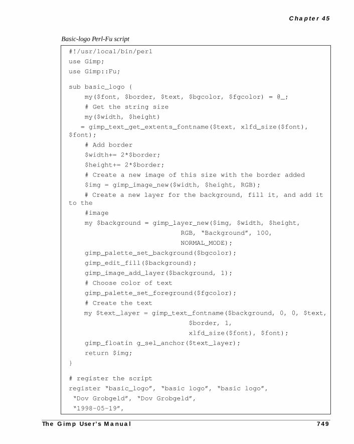
C h a p t e r 4 5
#!/usr/local/bin/perl
use Gimp;
use Gimp::Fu;
sub basic_logo {
my($font, $border, $text, $bgcolor, $fgcolor) = @_;
# Get the string size
my($width, $height)
= gimp_text_get_extents_fontname($text, xlfd_size($font),$font);
# Add border
$width+= 2*$border;
$height+= 2*$border;
# Create a new image of this size with the border added
$img = gimp_image_new($width, $height, RGB);
# Create a new layer for the background, fill it, and add itto the
#image
my $background = gimp_layer_new($img, $width, $height,
RGB, “Background”, 100,
NORMAL_MODE);
gimp_palette_set_background($bgcolor);
gimp_edit_fill($background);
gimp_image_add_layer($background, 1);
# Choose color of text
gimp_palette_set_foreground($fgcolor);
# Create the text
my $text_layer = gimp_text_fontname($background, 0, 0, $text,
$border, 1,
xlfd_size($font), $font);
gimp_floatin g_sel_anchor($text_layer);
return $img;
}
# register the script
register “basic_logo”, “basic logo”, “basic logo”,
“Dov Grobgeld”, “Dov Grobgeld”,
“1998-05-19”,
Basic-logo Perl-Fu script
T h e G i m p U s e r ’ s M a n u a l 7 4 9

A Tu t o r i a l F o r Pe r l G i m p U s e r s
area
nto
rget
ndfirstinto
FLOATING SELECTIONS
When a region has been selected through one of the selection routines, theoutlined by the selection may be copied to thecut-buffer through thegimp_edit_copy command. The cut-buffer may subsequently be pasted ia different layer through thegimp_edit_paste command. When a layer ispasted, it becomes afloating selection. This floating selection may be movedto its required position by thegimp_layer_set_offsets command, and ispasted by thegimp_floating_sel_anchor command. Another way ofdetermining the position of a pasted layer is to create a selection in the taimage before the cut-buffer is pasted.
This is illustrated in the Horiz-cat Perl-Fu script, which works on one image atakes another image as a parameter, which it concatenates to the right of theimage. Lines 13 through 28 show how the second image is copied and gluedthe first image.
7 5 0 T h e G i m p U s e r ’ s M a n u a l

C h a p t e r 4 5
#!/usr/local/bin/perl
use Gimp qw( :auto );
use Gimp::Fu;
sub horiz_cat {
my($img1, $drw1, $drw2) = @_;
# Get image 2
$img1 = $drw1->image();
my $img2 = gimp_drawable_image($drw2);
# Get sizes through OO syntax
my($w1, $h1) = ($drw1->width, $drw1->width);
my($w2, $h2) = ($drw2->width, $drw2->height);
# The new height is the maximum height of the images
my $hmax = $h1 > $h2 ? $h1 : $h2;
# Create an undo group
gimp_undo_push_group_start($img1);
# Resize the drawable layer to make room for the img
gimp_image_resize($img1, $w1+$w2, $hmax, 0, ($hmax-$h1)/2);
gimp_layer_resize($drw1, $w1+$w2, $hmax, 0, ($hmax-$h1)/2);
# Copy $drawable2 and paste it into the new space of$drawable1
# select all of img2
gimp_selection_all($img2);
# copy it to the clipboard
gimp_edit_copy($drw2);
# make a selection in img 1 in the position where it is to bepasted
gimp_rect_select($img1, $w1, ($hmax-$h2)/2, $w2, $h2, 0,0,0);
# paste and then anchor it
my $floating_layer = gimp_edit_paste($drw1, 0);
gimp_floating_sel_anchor($floating_layer);
# Close the undo group
gimp_undo_push_group_start($img1);
# Update the displaygimp_displays_flush(); return undef;}
Horiz-cat Perl-Fu script
T h e G i m p U s e r ’ s M a n u a l 7 5 1

A Tu t o r i a l F o r Pe r l G i m p U s e r s
Thehen
vi-me.
hen
thin
asfor
e anur-t a
n too not
ot to
ister
tive
THE PERL SERVER AND STANDALONE SCRIPTS
So far the scripts have all been started from the menu structure within menu.scripts can, however, be from the command line as a normal Perl program. Wrun this way, the script tries to connect to thePerl-Server, and if it fails, itlaunches Gimp on its own. If you plan to run several scripts this way, it is obously much faster to run the Perl-Server; launching Gimp takes quite a bit of tiThe Perl-Server may be started from the Xtns menu.
When a Perl-Fu script is run from the command line, the result is the same as wit is run through the menus, except that it may be run with the--output param-eter. This is in case the script saves the result to a file instead of displaying it wiGimp.
The file name for the--output allows special image-saving parameters, suchinterlace, quality factor, and so forth, to be set. See the Gimp::Fu man pagedetails. The normal rules about image and file types are still valid, so, to savimage as a GIF file, it must be converted from RGB to an indexed script. Crently, this functionality must be included in each script, but it is possible thafuture version of Gimp::Fu will include this conversion as an option.
Here are two invocations of the scripts declared above, but with output writtea JPG file and a PNG file. They can’t be saved as GIF because the scripts dindex the images.
This interface also enables running theperl debugger on the Perl-Fu scripts.
Note: The image is saved to the directory where Gimp was started from and nthe directory in which the scripts were invoked.
A SHELL FOR GIMP-PERL
When using the Perl-server, it is not necessary to use Gimp::Fu and the regfunction. Instead,Gimp::Net and a sub namednetmay be declared. For a sim-ple but powerful example of the use of Gimp without Fu, here is a an interacGimp-Perl shell that may be run from the command line:
uni -o /tmp/uni.png -size 100 -color “#5050ff”
basic-logo -o /tmp/bl.jpg -text “Perl rules”
7 5 2 T h e G i m p U s e r ’ s M a n u a l

C h a p t e r 4 5
riptnot
rl
Here is an example of an interactive session with this shell:
END NOTES, LINKS AND REFERENCES
NOTES
This tutorial has covered only a small part of the possibilities available to a scwriter. In particular, the following issues available to Gimp::Perl scripts havebeen covered:
• The possibility of writing customized Gtk interfaces.
• Writing full-fledged plug-ins that manipulate the tile data through the PeData Language (PDL) module.
• Using Perl::Gimp in a CGI environment.
• How to fill with gradients in a plug-in.
#!/usr/local/bin/perl
use Gimp;
use Term::ReadLine;
sub net {
$term = new Term::ReadLine;
while( defined ($_ = $term->readline(“Gimp> “))) {
$res = eval($_) . “\n”;
print(“Error: $@”), next if $@;
print “\n”;
Gimp> $img = gimp_image_new(100,100,RGB)
Gimp> $drw = $img->layer_new(100,100,RGB_IMAGE, “bg”, 100,\NORMAL_MODE)
Gimp> $img->add_layer($drw,-1)
Gimp> $img->display_new
Gimp> $drw->edit_fill
Gimp> gimp_displays_flush()
T h e G i m p U s e r ’ s M a n u a l 7 5 3

A Tu t o r i a l F o r Pe r l G i m p U s e r s
• How to do “free selections.”
LINKS AND REFERENCES
Marc Lehmanns Gimp page,http://gimp.pages.de
The online version of this tutorial,http://imagic.weizmann.ac.il/~dov/gimp/perl-tut.html
The Scheme tutorial this tutorial is based on,http://imagic.weizmann.ac.il/~dov/gimp/scheme-tut.html
The Gimp home page, http://www.gimp.org
Gimp Registry with Perl plug-ins,http://registry.gimp.org/
7 5 4 T h e G i m p U s e r ’ s M a n u a l


P A R T
X Advanced Installations• HOW TO PROVIDE FONTS TO GIMP
• TO MAKE OR NOT TO MAKE, PLUG-INS WITH GIMP


C H A P T E R
46 How To Get Fonts To GimpIn this chapter, you’ll find some basic informationabout how to make fonts available to Gimp inX-window.
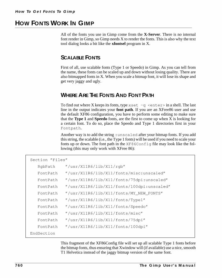
H ow To G e t F o n t s To G i m p
text
ome areand
eurerour
our
reoth
HOW FONTS WORK IN GIMP
All of the fonts you use in Gimp come from theX-Server. There is no internalfont render in Gimp, so Gimp needs X to render the fonts. This is also why thetool dialog looks a bit like thexfontsel program in X.
SCALABLE FONTS
First of all, use scalable fonts (Type 1 or Speedo) in Gimp. As you can tell frthe name, these fonts can be scaled up and down without losing quality. Theralso bitmapped fonts in X. When you scale a bitmap font, it will lose its shapeget very jaggy and ugly.
WHERE ARE THE FONTS AND FONT PATH
To find out where X keeps its fonts, typexset -q <enter> in a shell. The lastline in the output indicates yourfont path. If you are an XFree86 user and usthe default XF86 configuration, you have to perform some editing to make sthat theType 1 andSpeedofonts, are the first to come up when X is looking foa certain font. To do so, place the Speedo and Type 1 directories first in yFontpath .
Another way is to add the string:unscaled after your bitmap fonts. If you addthis string, the scalable (i.e., the Type 1 fonts) will be used if you need to scale yfonts up or down. The font path in theXF86Config file may look like the fol-lowing (this may only work with XFree 86):
This fragment of the XF86Config file will set up all scalable Type 1 fonts befothe bitmap fonts, thus ensuring that Xwindow will (if available) use a nice, smoT1 Helvetica instead of the jaggy bitmap version of the same font.
Section ”Files”
RgbPath ”/usr/X11R6/lib/X11/rgb”
FontPath ”/usr/X11R6/lib/X11/fonts/misc:unscaled”
FontPath ”/usr/X11R6/lib/X11/fonts/75dpi:unscaled”
FontPath ”/usr/X11R6/lib/X11/fonts/100dpi:unscaled”
FontPath ”/usr/X11R6/lib/X11/fonts/MY_NEW_FONTS”
FontPath ”/usr/X11R6/lib/X11/fonts/Type1”
FontPath ”/usr/X11R6/lib/X11/fonts/Speedo”
FontPath ”/usr/X11R6/lib/X11/fonts/misc”
FontPath ”/usr/X11R6/lib/X11/fonts/75dpi”
FontPath ”/usr/X11R6/lib/X11/fonts/100dpi”
EndSection
7 6 0 T h e G i m p U s e r ’ s M a n u a l

C h a p t e r 4 6
e
t-Fu
nd
er-
l-
e.mp,
yount.wehisants
To find out what kind ofType 1 fonts you have, change the directory to the Typ1 dir, and read thefonts.dir file (e.g.,cd /usr/X11/lib/X11/fonts/Type1 && more fonts.dir ) in a terminal window. All of your availableType 1 fonts will be displayed. One of the most common reasons for a Scripto fail is that the specified Script-Fu font isn’t available. This makes the scriptbug,and there will be no output.
INSTALLING FONTS
TYPE 1 FONTS INSTALLATION AND THETYPE1INST PROGRAMWe will only coverType 1 fonts (postscript fonts), other font types are beyondthe scope of this chapter.
Download a program called type1inst (written by James Macnicol) fromftp://sunsite.unc.edu/pub/Linux/X11/xutils or one of its mirrors.
Preparing For InstallationAt the time of this writing, the file is calledtype1inst-0.6.tar.gz.Unpack the program like you did with the Gimp archive (see “Obtaining AInstalling Gimp” starting on page 43). Copy the filestype1inst andt1embedto a directory in your PATH (for example,/usr/local/bin) .
To see your PATH, executeecho $PATH in a shell. If you aren’t the systemadministrator, then you probably can’t install files in system directories. To ovcome this problem, create abin directory in your home directory and install thetype1inst program there. To include the program in your PATH, do the folowing if you runBash, Sh or Ksh as your shell:
export PATH=$PATH:$HOME/bin
Copying The Fonts To The Fonts dirCopy the Type 1 fonts that you want to install in a directory of your own choicIf you have a large font collection and you want easy font management in Giinstall anxfontserver or install the fonts in different directories with 20 fonts ineach.
Font ManagementHere’s how we manage fonts at Frozenriver: Karin needs a lot of fonts, but ifload all fonts into X and Gimp, it becomes hard to choose and find the right foWe have solved this by making different directories for each type of font, e.ghave one directory for artistic fonts, one for strictly business fonts, and so on. Tmakes it easy for Karin to load and unload the fonts depending on what she wto do.
T h e G i m p U s e r ’ s M a n u a l 7 6 1
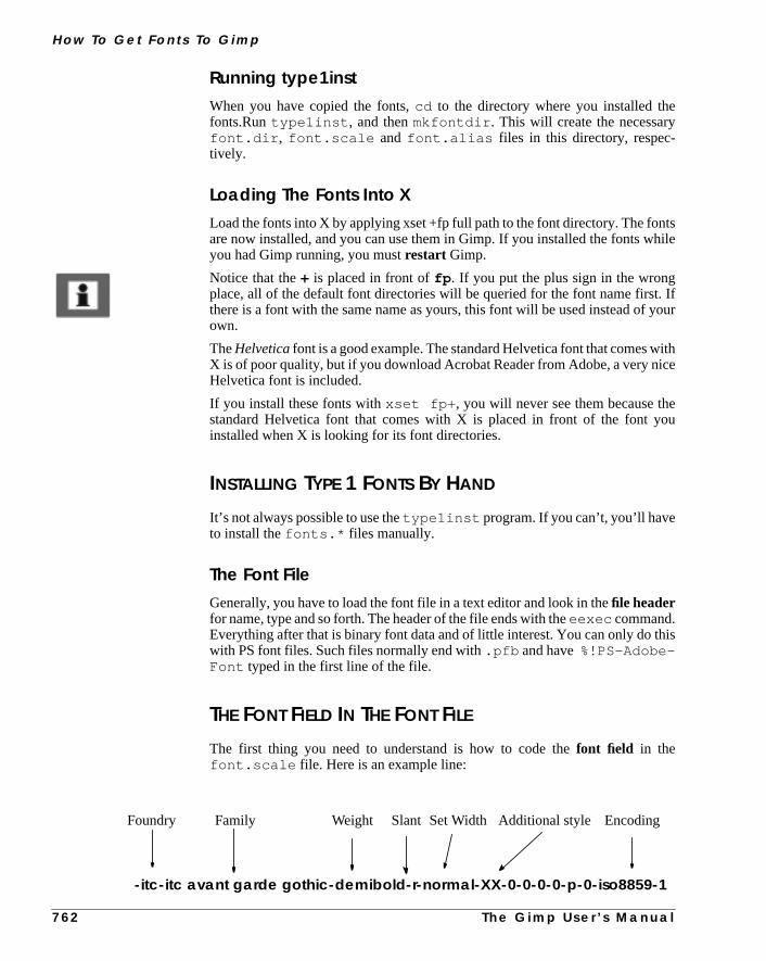
H ow To G e t F o n t s To G i m p
tshile
Ifyour
ithce
eou
his
Running type1instWhen you have copied the fonts,cd to the directory where you installed thefonts.Runtype1inst , and thenmkfontdir . This will create the necessaryfont.dir , font.scale and font.alias files in this directory, respec-tively.
Loading The Fonts Into XLoad the fonts into X by applying xset +fp full path to the font directory. The fonare now installed, and you can use them in Gimp. If you installed the fonts wyou had Gimp running, you mustrestart Gimp.
Notice that the+ is placed in front offp . If you put the plus sign in the wrongplace, all of the default font directories will be queried for the font name first.there is a font with the same name as yours, this font will be used instead ofown.
TheHelveticafont is a good example. The standard Helvetica font that comes wX is of poor quality, but if you download Acrobat Reader from Adobe, a very niHelvetica font is included.
If you install these fonts withxset fp+ , you will never see them because thstandard Helvetica font that comes with X is placed in front of the font yinstalled when X is looking for its font directories.
INSTALLING TYPE 1 FONTS BY HAND
It’s not always possible to use thetype1inst program. If you can’t, you’ll haveto install thefonts.* files manually.
The Font FileGenerally, you have to load the font file in a text editor and look in thefile headerfor name, type and so forth. The header of the file ends with theeexec command.Everything after that is binary font data and of little interest. You can only do twith PS font files. Such files normally end with.pfb and have%!PS-Adobe-Font typed in the first line of the file.
THE FONT FIELD IN THE FONT FILE
The first thing you need to understand is how to code thefont field in thefont.scale file. Here is an example line:
-itc-itc avant garde gothic-demibold-r-normal-XX-0-0-0-0-p-0-iso8859-1
Foundry Family Weight Slant Set Width EncodingAdditional style
7 6 2 T h e G i m p U s e r ’ s M a n u a l

C h a p t e r 4 6
s
ine.
ing.
Extracting DataLoad thepfb in a file editor (likevi file.pfb ) in a terminal such as xterm,and search for data. Here’s what to look for:
• Foundry: The registered name of the font foundry, usually a companyname. This was written in the PS font file:usage: 24954 31846%%ITC Avant Garde Gothic is a registered trademarkof International Typeface . This means that the font will useITC as Foundry.
• Family: The font family to which the font belongs. There are usually alot of font files in a font family, all with different characteristics (such abold, thin, condensedand so forth). Contents of the font file’s read-only isdef/FamilyName (ITC Avant Garde Gothic) , which willdisplay asitc avant garde gothic in the family field.
• Weight: The weight of the font (for example,medium, bold, thin and soforth). This is the information in the PS filereadonly def/Weight(Demi) , which will putdemibold in the weight field.
• Slant: Theposture of the font. If there is no slant information for thefont, it will display as Roman oruprightposture, and there will be anr inthe slant field. If there is slant information (such asGothic Demi Oblique)the slant is Oblique, and there will be ano in the slant field.
• Set Width: This is the horizontal width. Here, you have to search thefont name.Condensed is an example of a width type.
• Additional Style: This is a rarely used option for additional styles; it’shardly ever used in PS fonts.
• Encoding: This is what type of languages the font supports. Thisexample from the PS filedef/Encoding StandardEncoding willend up asiso8859-1; for example,isolatin1 in the encoding field
• The rest is the same as in the example line. It’s the standard PS font l
The following section provides some tables that can help you with your decodThey are taken from the source of thetype1inst program.
Generally,type1inst will make the job for you. If the Foundry informationisn’t right, then you can look in thefont file or the log file which type1instcreates. Most of the time, it’s quite easy to figure out what’s missing.
T h e G i m p U s e r ’ s M a n u a l 7 6 3

H ow To G e t F o n t s To G i m p
TABLES
Table 46.1 The Foundry table
Company FoundryAdobe adobePublishers Paradise paradiseBigelow & Holmes b&hBitstream bitstreamInternational Typeface Corporation itcIBM ibmLETRASET letrasetMonotype Corporation monotypeSoftMaker softmakerURW urwJonathan Brecher brecherBrendel Informatik brendelA. Carr carrFontBank fontbankHershey hersheyA.S.Meit meitAndrew s. Meit meitS.G. Moye moyeD. Rakowski rakowskiDavid Rakowski rakowskiReasonable Solutions reasonableSouthern Software southernTitle Wave titlewaveZSoft zsoft
7 6 4 T h e G i m p U s e r ’ s M a n u a l

C h a p t e r 4 6
Table 46.2 The Weight table
Weights Weightbook bookdemibold demiboldsemibold demibolddemi demiboldsemi demiboldextrabold extraboldboldface boldbold boldheavyface heavyfaceheavy heavyultrablack ultrablackextrablack extrablackultra ultrablack blackextralight extralightlight lightthin thinsuper supernormal mediumregular regularroman regular
Table 46.3 The Slant table
Slants Slantitalic iroman rregular rcursive ikursiv ioblique oobl oslanted oupright rinclined i
T h e G i m p U s e r ’ s M a n u a l 7 6 5

H ow To G e t F o n t s To G i m p
Table 46.4 The Set Width table
Widths Set Widthextracondensed extracondensedcondensed condensedcond condensedsans sanswide widecn condensednarrow narrowextracompresse extracompressecompressed compressedextraextended extraextendedextended extendedexpanded expandednormal normal
Table 46.5 The Additional style table
Styles Stylealt alternatebeginning beginningdisplay displaydfr dfrending endingep expertexp expertornaments ornamentsosf oldstylefiguresoutline outlinesc smallcapsshaded shadedshadowed shadowedstencil stencilswash swashsw swashone onetwo twothree threefour foura alternate
7 6 6 T h e G i m p U s e r ’ s M a n u a l


C H A P T E R
47 Compiling Plug-insIn this chapter, we will explain how to compile plug-insso they can be used in Gimp.

C o m p i l i n g P l u g - i n s
p.
e is.
ted totion is
i-ioneed
eedm-
ut
er’songes,
ateug-gle
04,
COMPILE
A plug-in is a program that can’t run on its own; it needs to be started by GimMost of the time, plug-ins are distributed in thesource code. All programs havea source code (if they aren’t written directly in machine code). The source codwritten in a language humans can understand, such as C, C++ and so forth
The computer doesn’t understand C or C++, so the code needs to be translamachine code that the computer understands and can execute. This translacalledcompiling.
Before you can compile, you must have acompiler installed. You must also haveprograms such asmake or ld. Those tools are standard in all major Linux distrbutions, but you may not have them installed. Consult your Linux distributmanual for information about how to install the development packages you nto be able to compile.
If you work in a Solaris environment, and you chose to installDevelopment systemsupportwhen you installed Solaris, you already have nearly everything you nfor compiling. What you need now is a compiler. You can get GCC (GNU C- copiler) for free. Seehttp://www.sunfreeware.com/ for where to down-load GCC for Solaris.
DIFFERENT WAYS OF COMPILING
There are four common ways to compile: withGimptool, Make, Configureor plain CC. This chapter covers the basics of different types of compiling, bnot extras, such as special compiler flags and debugging.
We really want you to try to compile a plug-in, even if you aren’t a programmor hacker. If you have a friend who is a UNIX programmer, we still think that ita good idea to read this chapter and give it your best shot. If it goes totally wrin spite of your having followed the instructions to the best of your capabilitithen by all means, call in your friend.
GimptoolGimptool is a program that is integrated with Gimp. It was designed to facilitthe compilation of plug-ins, so using Gimptool is the easiest way to compile plins for Gimp. The plug-in you build, however, can’t contain more than a sinsource file. This means that you can only use thegimp-tool command to buildand install plug-ins that consist of one.c file. It can’t be modularized to several.c files (we don’t meanheaderfiles, i.e., files ending with.h) . To find outmore about Gimptool, see Appendix B; “The gimp-tool Man Page” on page 8and “Using gimp-tool To Compile The Plug-in” on page 772.
Compiling With Make, Configure Or Plain CcThere are three ways to compile:
7 7 0 T h e G i m p U s e r ’ s M a n u a l

C h a p t e r 4 7
uilds:
-
n’tNU
ools
1. Make is a program that executes a specification file commonly calledMakefile. By running this file, it willcompilethe program with the help of thecompiler.
2. Configure is a program thatgenerates aMakefile. After doing this, youwill have to runMake to compile.
3. The most basic, but also the hardest way, is to use thecompiler to compilethe code without a help program.
HOW TO OBTAIN AND INSTALL THE SOURCE CODE
Most of the time, you will go to theplug-in registry or the Gimp.org FTPsite to obtain/download the source code. Other sources of information areGimpNewsand the Gimp developer/Gimp usermailing lists.
Unpacking The Source CodeWhen you havedownloadedthe source code, you mustunpack it. Usually, thecode ends withxxx.c.gz , xxx.tgz or xxx.tar.gz .
Thexxx.c.gz can be decompressed with:
gunzip xxx.c.gz
Thexxx.tgz andxxx.tar.gz archives can be unpacked with:
cat xxx.tgz | gunzip|tar xvf -
Before you unpack the source, move it to a new directory. Then unpack and bthe plug-in. For example, in an Xterm window, enter the following command
If the plug-in source file ends withxxx.c , then the file has already been decompressed. If you have usedNetscape to download the file, you can save it.Remember, however, that Netscape often tries todecompressdownloadedarchives and that it sometimes fails to do this.
If this is the case, check the source filexxx.c with a file viewer such asMore(for example,more xxx.c ). If you can’t read what’s in the file, then it’s notdecompressed. To fix it, enter:
mv xxx.c xxx.c.gz && gunzip xxx.c.gz.
COMPILING THE CODE
We will useGNU tools to compile the code. If you are using a system that doeshave GNU tools installed, then you have two options: Download and install Gtools (beyond the scope of this book) or use the system’s own tools.
There is no big difference between GNU and system tools. Some of the GNU tcan be recognized by the fact that their names start with the letterg. For example,
mkdir build; mv xxx.tgz build; cat xxx.tgz | gunzip | tar xvf -
T h e G i m p U s e r ’ s M a n u a l 7 7 1

C o m p i l i n g P l u g - i n s
here
d oute-
e
ild-
tion
si-
st
h
re
the GNU compiler is calledgcc and the system’s own compiler is calledcc .Wethink that this won’t make any difference here, but we can’t be sure because tare a lot of different Unix systems out there, and we can’t cover them all.
FINDING OUT HOW TO COMPILE THE PLUG-IN
When you have downloaded and unpacked the plug-in source, you have to finhow to compile it. The plug-ins are often packed with several other files. Somtimes, there is aREADMEor INSTALL file. If you find one of these files, alwaysread it.
Most of the time, you will find information about how to compile and install thplug-in in one of these files. You can also look in thehead of the C code file.If there is no information, follow our examples here.
TheREADMEfile should tell you whether you need additionallibraries to com-pile the plug-in. For example, you may need thelibtif library and header filesto compile the plug-in. If you don’t have these libraries or header files, the buing of the plug-in will fail.
To find out if you have these libraries or other required programs, read the seccalled “Installing A Source Distribution” on page 48.
Compiling a library is a bit different than compiling a plug-in, but the start is bacally the same.
If the plug-in you’ve downloaded is a single file or if the archive you juunpacked has noMakefile (it may be calledMakefile , Makefile.clas-sic , MAKEFILE, etc.) or configure file, then you have to compile it directly witGimptool or GCC, or create a Makefile or configure script.
If there is a Makefile, then you can usemake to compile the plug-in. Before youbegin, check the Makefile to find out whether it is correct for your system. If theis aconfigure script, then use the configure script to generate a Makefile.
USING GIMP-TOOL TO COMPILE THE PLUG-IN
This is the easiest way to compile a single source plug-in:
gimptool --build plugin.c
whereplugin.c is the name of the plug-in source file. This will most likelybuild your plug-in.
7 7 2 T h e G i m p U s e r ’ s M a n u a l

C h a p t e r 4 7
ears,
on
edieso-is
However, if the build process failed and a message such as the following appthen readUsing GCC To Compile The Plug-inand compile it with GCC directly.
When you have compiled it, you will probably also want toinstall the plug-in.You can do this by invokingGimptool:
gimptool --install plugin.c
This will bothcompilethe plug-in andinstall it in your personal.gimp directory.If you are a system administrator and want to install the plug-in for all usersyour system, then use Gimptool like this:
gimptool --install-admin plugin.c
This will compile and install the plug-in in thesystem-wide Gimp directory.
USING GCC TO COMPILE THE PLUG-IN
A First TryIf the file is namedplugin.c , then compile it with:
gcc -o plug-in plugin.c.
The-o flag tells the compiler that the final output (the plug-in) should be namplug-in. If your C compiler (GCC) is configured to search the standard directorfor the include andlibrary files and those files are in the standard directries, then the plug-in will compile cleanly. However, it is quite unlikely that thwill happen; you will probably need specific Gimp libraries and include files.
/tmp/cca017741.o(.text+0xc): undefined reference to ‘something’
/tmp/cca017741.o(.text+0x87): undefined reference to ‘something’
T h e G i m p U s e r ’ s M a n u a l 7 7 3

C o m p i l i n g P l u g - i n s
t you
il-
ys-
The following example shows what appeared when we compiled thewaterse-lect.c file in the way we just described:
LibrariesThis happens when the necessary libraries aren’t linked to the executable thaare trying to build. Alibrary is a set offunctions, for example, a function thatcreates awindowor ascrollbar. The compiler checks that the functions are avaable for the plug-in to use when it is executed.
Another TryNow, let’s try to compile it with:
gcc -o plug-in plugin.c -L/usr/local/lib -lgtk-lgimp
Now the plug-in compiles cleanly on the system. If you work on Sun Solaris stem, add the following before even starting to think about libraries:
-I/usr/local/include
Include FileThe error messages telling you that aninclude (header file) is missing looks likethis:
waterselect.c:39: gtk/gtk.h: No such file ordirectory
/tmp/cca017741.o(.text+0xc):undefined reference to `gimp_main’
/tmp/cca017741.o(.text+0x87):undefined reference to `gdk_input_list_devices’
/tmp/cca017741.o(.text+0xc5):undefined reference to `g_strcasecmp’
/tmp/cca017741.o(.text+0x626):undefined reference to `gtk_preview_get_type’
/tmp/cca017741.o(.text+0x632):undefined reference to `gtk_object_check_cast’
/tmp/cca017741.o(.text+0x63d):undefined reference to `gtk_preview_draw_row’
/tmp/cca017741.o:In function `update_buckets’:
/tmp/cca017741.o(.text+0x682):undefined reference to `gtk_widget_draw’
/tmp/cca017741.o:In function `update_gimp_color’:
/tmp/cca017741.o(.text+0x6e2):undefined reference to \`gimp_palette_set_foreground
7 7 4 T h e G i m p U s e r ’ s M a n u a l

C h a p t e r 4 7
y the.
at
ies
ideom
he
Although this message tells us that a file namedgtk.h is missing, this is notalways the case. A more correct answer is that the compiler (more accuratelpreprocessorcompiler) can’t find it in the directories it was configured to search
To tell the compiler where to search for the file, add the following:
-I/where/to/search
Because the file is located in/usr/local/include/gtk , and the error was“can’t find gtk/gth.h ,” this tells us that the compile line will be:
gcc -o plug-in plugin.c -L/usr/local/lib \ -lgimp -lgtk -I/usr/local/include
-I/usr/local/include that was added tells the compiler to search thdirectory forinclude files (in our case,gtk/gtk.h ). The compiler will find thefile because it will add:
gtk/gtk.h
to:
/usr/local/include
resulting in:
/usr/local/include/gtk/gtk.h
which is where the file is located.
The -L Flag And How To Find Out Which Libs To LinkThe-L flag works the same way. It tells the compiler where to search for librar(in this case, the librarieslibgimp.so and libgtk.so ). The -lgimp is ashortcut, so we don’t have to writelibgimp.so .
To determine which libraries to add and which directories to include, look insthe code (generally located in the beginning of the file). Here’s an example frthewaterselect.c file:
This code tells us that the compiler will include five files when it compiles tcode. The first three are ordinary standard Cinclude files and the other ones arespecial Gimp and GTK files.
#include <stdlib.h>
#include <stdio.h>
#include <math.h>
#include <gtk/gtk.h>
#include ”libgimp/gimp.h”
T h e G i m p U s e r ’ s M a n u a l 7 7 5

C o m p i l i n g P l u g - i n s
h the
(in
p.nd
e.ns.
d
The -I FlagThe standard C header files are located in a standard include directory, whiccompiler will search. However, thegtk.h andgimp.h files aren’t in a standarddirectory, so tell the compiler (-I flag ).
If the -I flag is /usr/local/include , the compiler will try to get thegtk.h files in:
/usr/local/include/gtk/gtk.h.
The source code lines can also give us a hint about which libraries to link withthis case,libgimp andlibgtk ). The standard C library and Math library arelinked by default on most systems.
How To Use Gimptool To Get Lib And Include FlagsIf you invoke Gimptool with the commandgimptool --libs , it will replywith the following (site dependent):
It will give you all of the libraries and -L flags that were used to compile GimThis can be very useful if you compile a plug-in that needs the TIFF library athe Gimptool libraries. Then, you can invoke gcc like this:
gcc -o plug-in ‘gimptool --libs‘ -ltiff plugin.c
Gcc will now compile and link your plug-in with all Gimp libraries, in addition tothe TIFF library. If you want to include allinclude flags, invoke Gimptool likethis:
gimptool --cflags
It will reply with a list of theCFLAGS used to compile Gimp.
What To Do When There Are Several Source FilesA plug-in can contain more that one C source code file. If the extra file is aheaderfile (namedplugin.h ), then we can compile the plug-in just as we did beforThe header file is a file that specifies functions and how to call these functioLook at the files (or just the header file) to find out whatinclude directories toinclude and which libraries to link.
If the plug-in is built up of several files (such as:pluginmain.c ,pluginpart1.c , pluginpart2.c , etc.), compile each part separately anthen link them to an executable plug-in.
-L/usr/local/lib -lgimpui -lgimp \-L/usr/local/lib -L/usr/openwin/lib \-R/usr/openwin/lib -lgtk -lgdk -lglib -lXext \-lX11 -lsocket -lnsl -lm
7 7 6 T h e G i m p U s e r ’ s M a n u a l

C h a p t e r 4 7
be
d totnds
out
aremuse
a lot
d-lotide
entyou
pile
Object files must be made out of each part. These object files will thenlinked, thus creating the final executable plug-in. For example:
On the first three lines, the object files are made. The compiler is instructemake object files by adding the-c flag. When object files are made, we don’need to worry about libraries, we only have to make sure that the compiler fithe include files which is why only the-I flag is used when the object files arecreated.
On the last line, the final plug-in is made. Here, we don’t need to worry abinclude files, we only have to make sure that welink the libraries needed by theplug-in. When the object files are made, descriptions of library function callsincluded by including header files. The plug-in object file happily uses thebecause it assumes that it will be linked to these libraries later on. You can alsothe gimptool --cflags and gimptool --libs commands to includelibraries and directories. We recommend using Gimptool to avoid errors, andof typing.
On the last line, the compiler is told that the final outcome will be a plug-in by ading -o plug-in , then the object files made in the first three lines. Because aof library functions have been used in the object files, add the libraries to provthese functions to the plug-in by adding-lgimp , -lgimpui . Tell the compilerwhere to search for the libraries by adding-L/usr/local/lib . The directory/usr/lib and/lib are also searched by default.
When building a plug-in that consists of several parts, compiling the differparts manually is often the wrong method to use. If something goes wrong,will have to type all your commands again. The solution is to create aMakefile.A Makefile is a specification that the Make command uses as an input to comthe entire plug-in with the help of the compiler.
gcc -c pluginmain.c -I/usr/local/include
gcc -c pluginpart1.c -I/usr/local/include
gcc -c pluginpart2.c -I/usr/local/include
gcc -o plug-in pluginmain.o pluginpart1.o \pluginpart2.o -L/usr/local/lib -lgtk -lgimp \ -lgimpui -lmpeg
T h e G i m p U s e r ’ s M a n u a l 7 7 7

C o m p i l i n g P l u g - i n s
r-ch
it,
e
HOW TO CREATE A MAKEFILE AND HOW TO USE IT
Now, we’ll take a look at how to create a simple Makefile. This will help us undestand the structure of a Makefile, so that we’ll know how to edit a Makefile whicomes with a plug-in. The following is an example of a generic Makefile:
This Makefile builds the object files first, and then links the plug-in. To usereplace theheader, object andsourcefiles with the correct ones. You can alsochange what libraries to link and what directories to search forlibs andincludes. The CFLAG -O2 represents optimization of the executable. Noticthe tab at the last line. If you forgot the tab you will get this error message:
Makefile:11: *** missing separator. Stop.
CC = gcc
INCDIR = -I/usr/local/include -I/usr/local/tiff/include
CFLAGS = -O2
LIBDIR = -L/usr/X11/lib -L/usr/local/lib
LFLAGS = -lgimp -lgtk -lX11 -ltiff -lgimpui
HEDERS = plugin.h plugin2.h
SOURCES = pluginmain.c pluginpart1.c pluginpart2.c
OBJECTS = pluginmain.o pluginpart1.o pluginpart2.o
plug-in: $(OBJECTS) $(HEADERS)
$(CC) $(CFLAGS) -o $@ $(OBJECTS) $(INCDIR) $(LIBDIR) $(LFLAGS)
7 7 8 T h e G i m p U s e r ’ s M a n u a l

C h a p t e r 4 7
e is
ral
c-ay.ith
to
hat
end
A Makefile ExampleHere’s how the Makefile looked when we built theGuashplug-in at our Linuxsystem (there is a Makefile included in the distribution of Guash; this examplonly for training):
The important thing is tochangeand maybeadd include and library directo-ries so it will fit your system. Remember that you can write a Make-file in sevedifferent ways, this is only one of many.
VariablesWhen you edit your Makefile, it may not look like this, but with the basic instrution and knowledge about how to compile, you should be able to edit it anywThe first eight lines are variables that are called later on lines 10 and 11 w$(VARIABLE) . The special$@variable is an internal variable that expandsthe first word in the line above it (i.e., Guash, in this example).
To build the plug-in, invoke Make by enteringmake or:
make -f WhatYouCallYourMakefile.
Make will invokegcc to build your object files and to link your executable.
A common error that occurs when you use a Makefile to compile a plug-in tcomes as an archive is that the Make-program complains aboutdependencies.If so, remove the.deps directory (rm -rf .deps ) in the building directory.Dependencies can also be included in the Makefile. You will find them at theof the file. Remove them, and everything should work fine.
CC = gcc
INCDIR = -I/usr/local/include
CFLAGS = -O2
LIBDIR = -L/usr/local/lib
LFLAGS = -lglib -lgdk -lgtk -lgimp
HEADERS = guash-directory.h guash-banner.h
SOURCES = guash.c
OBJECTS = guash.o
guash: $(OBJECTS) $(HEADERS)
$(CC) $(CFLAGS) -o $@ $(OBJECTS) $(INCDIR) $(LIBDIR)$(LFLAGS)
T h e G i m p U s e r ’ s M a n u a l 7 7 9

C o m p i l i n g P l u g - i n s
ec-
the-in
ory
theror
ll
How To Use Gimptool In A MakefileThis is the way to change the previous Makefile using Gimptool instead of spifying all of the libraries and include directories.
There is a lot less typing involved, and you may also be sure of getting all ofnecessary Gimp-related libraries and includes into the Makefile. If the plugneeds more libraries or include directories, you can add it after thegimptoolcommand:
INCDIR = `gimptool --cflags` -I/usr/opt/include
or like this:
LIBDIR = `gimptool --libs‘ -L/opt/lib -ltiff
CONFIGURE TO AUTOMATE THE BUILDING PROCESS
The configure script that comes with the plug-in is a way toautomatethe pro-cess of making a Makefile. The configure script will try to find theinclude filesand libraries that the plug-in needs.
If you are on a common UNIX platform like Solaris or Linux, then it’s simple tuse a configure script. To build your plug-in, enter the following in the directowhere you unpacked the plug-in:
./configure && make
Now, the plug-in will be compiled and ready to use. Make sure that you are indirectory where the configure script is located; otherwise, you will get this ermessage:
bash: ./configure: No such file or directory.
If you don’t have a certain file or library, or the script can’t find it, then you wihave to install it or tell the script where to find it.
CC = gcc
INCDIR = `gimptool --cflags`
CFLAGS = -O2
LIBDIR = `gimptool --libs‘
HEADERS = guash-directory.h guash-banner.h
SOURCES = guash.c
OBJECTS = guash.o
guash: $(OBJECTS) $(HEADERS)
$(CC) $(CFLAGS) -o $@ $(OBJECTS) $(INCDIR) $(LIBDIR)
7 8 0 T h e G i m p U s e r ’ s M a n u a l
e’s
e
hatou
l
To find out how to tell the script where to findinclude files and libraries, invokethe script like this:
./configure --help
This will result in several lines of flags that you can supply the script with. Heran extract of the most important flags that you can include in your script:
--libdir=DIR
--includedir=DIR
With these two flags you can add aninclude/library directory like this:
--includedir=/your/includedir.
If you want to add more than oneinclude directory, you have to do it this wayif you work in an ordinary shell:
If you are working in aC shell, then you have to do it like this:
If you want to add more than onelibdir , enter the same commands as for thCFLAGS, but type:LDFLAGS instead.
You may run into several problems, especially if you are using a UNIX dialect tis different from what the authors of the configure script were working on. If yrun into a problem, first try to add all of the libraries andinclude directories tothe script with theFLAGSor manually in the generated Makefile. If this stildoesn’t solve the problem, try writing to the Gimp mailing list.
export CFLAGS=”-I/one/includedir -I/another/includedir”
setenv CFLAGS ”-I/one/includedir -I/another/includedir”


P A R T
XI Appendixes• INITIATION FILES AND COMMAND LINE SWITCHES
• MAN PAGES
• SIOD REFERENCE
• PERL-FU MAN PAGES
• LINKS AND REFERENCES

A P P E N D I X A
Gimp Start Flags And rcfilesOrdinarily, Gimp is launched by an icon or a menu inyour favorite window manager, but you can alsostart it manually. There are several initiation files thatcontrol the behavior of Gimp.

G i m p S t a r t F l a g s A n d r c f i l e s
e
-you
gs
GIMP COMMAND LINE SWITCHES AKA FLAGS (OPTIONS)An excellent source of information about thecommand line switchesandenvironments that Gimp sup-ports can be found in the Gimpman page. It’s located in thedoc dir in your Gimp source distribution,and normally you only have to enter the commandman gimp after you have installed Gimp to open thman page.
All of this is done in a shell, such as in anxterm or rxvt window. As we mentioned earlier, you have probably hidden all this in your Window Manager so you only have to click on an icon or open a menu. Ifwant to testflags and differentenvironments or even run Gimp without Xwindow, you must do this in ashell.
Typing gimp --help or gimp -h and pressing Enter will result in a short description of available flathat you can give Gimp:
[olof@olof olof]$ gimp --help
Usage: gimp [option ...] [files ...]
Valid options are:
-h --help Output this help.
-v --versionOutput version info.
-b --batch <commands>Run in batch mode.
-n --no-interfaceRun without a user interface.
--no-data Do not load patterns, gradients, palettes, brushes.
--verbose Show startup messages.
--no-splashDo not show the startup window.
--no-splash-imageDo not add an image to the startup window.
--no-shm Do not use shared memory between Gimp and its plug-ins.
--no-xshm Do not use the X Shared Memory extension.
--display <display>Use the designated X display.
[olof@olof olof]$
7 8 6 T h e G i m p U s e r ’ s M a n u a l

A p p e n d i x A
plash
of
t tothese
te
on’tystem
t hasnly),
d
ttings.t youredit
e is aplay
The -h and --help flags obviously printed out the above message. The-v and -- version flags showwhat version of Gimp you are running (this information is also available in the About dialog and the sscreen that shows up when you start Gimp). It will typically look like this:
[olof@olof olof]$ gimp -v
GIMP version 1.0
Always visit www.gimp.org, ftp.gimp.org or one of its mirrors to get the newest stable versionGimp.
BATCH MODE AND NO-INTERFACE
The-b and--batch options allow you to execute Gimp with arguments to run. This is ideal if you wanexecute a lot of commands to a lot of files. Otherwise, it would be quite annoying to have a GUI do allactions (open image,apply commands,saveimage,openanother image, apply command etc.). The<com-mands> shown earlier is a Script-Fu that will do the actual work for you (even if you can execuordinarygimp pdb commands directly).
-n and--no-interface are suitable if you run Gimp in batch mode because most of the time you dwant to have a user interface if you are running a batch. This will also save some memory and sresources. Here is an example of two batch commands:
gimp -n -b ’(gimp-procedural-db-dump ”pdb_dump.tmp”)’ ’(gimp-quit0)’
These will dump Gimp’s pdb database to a file calledpdb_dump.tmp in your working directory. Here isan example of a custom script that is invoked by Gimp (my-script is your own personal custom script):
gimp -n -b ’(my-script 1 ”\”Sample text.\””)’ ’(gimp-quit 0)’
The(gimp-quit 0) is so Gimp quits gracefully and returns the command prompt to you.
If you don’t have X-window up and running (i.e., you are running your UNIX session in a console thano graphic capabilities or you have a modem connection to your UNIX host with a vt100 terminal othen you still can run Gimp in batch mode; just do it like this:
Xvfb :1 -screen 0 10x10x8 -pixdepths 1 &
gimp --display :1.0 -n -b ’<commandos> ’ ’(gimp-quit 0)’
This will fire up an invisible X-server, in which you run Gimp.
More OptionsAs you saw above, we introduced a new flag,--display . Because X lets you run Gimp on one host andisplay it on another, you have to specify on which display to run Gimp’s user interface.
Normally you run and display Gimp on the same host, and you don’t have to barter about display seHere’s an example of how to use the display option in Gimp. Say that you have a “supercomputer” acampus running UNIX, and this computer has Gimp installed. Then, it would be more than efficient tohuge Gimp images at this computer while displaying them at your local workstation or X-terminal. Herquick how to. At your workstation, you will execute a command allowing the supercomputer to disGimp on your workstation:
T h e G i m p U s e r ’ s M a n u a l 7 8 7

G i m p S t a r t F l a g s A n d r c f i l e s
do now
y (atave
ourd tell
, bettert, etc.,
-at we
system
t off.
dif-
es,
[olof@olof olof]$ xhost niceriver.frozenriver.com (my localsupercomputer ;)
niceriver.frozenriver.com being added to access control list
The second line enabled the supercomputer to access our X-server at our workstation. All we have tois to telnet , or rlogin or rsh to the supercomputer:
[olof@olof olof]$ rlogin niceriver.frozenriver.com
[olof@niceriver olof]$
Now, we are logged in to the supercomputer. All we have to is open Gimp and tell it where to displaolof.frozenriver.com) , and which display to use at olof.frozenriver.com. Because we only hone display atolof , we will use display number 0:
gimp --no-xshm --display olof.frozenriver.com:0.0
Now, Gimp will display at your workstation and you can work with it just as if you had run Gimp at yworkstation. When you are finished with Gimp you just have to log out from the supercomputer anyour workstation that you don’t want the supercomputer accessing your X-server:
[olof@olof olof]$ xhost - niceriver.frozenriver.com
niceriver.frozenriver.com being removed from access control list
The last line tells us that the supercomputer no longer can access our X-server. There are, of courseways to handle remote display, that have better security, automatic transfer of the display environmenbut that is beyond the scope of this book.
We introduced another new option earlier,--no-xshm , which tells Gimp not to try to use X-shared memory. We have to do this because we ran Gimp on a different host. If we run Gimp on the same host thdisplayed Gimp at, we can use X-shared memory to speed things up a little bit, and also to saveresources. There is another shared memory flag,--no-shm , which tells Gimp not to share memory with itsplug-ins. It’s generally good to let Gimp do this, but if you encounter problems it can be wise to turn i
--no-splash tells Gimp not to show the splash when it starts. If you just tell Gimp--no-splash-image , then the splash will be shown, but without the image.
-- verbose will start up Gimp a little more verbosely and you will see in the shell how it's phrasing theferent initialization files..
[olof@olof olof]$ gimp --verbose
parsing ”/home/olof/.gimp/gtkrc”
parsing ”/usr/local/share/gimp/gimprc”
parsing ”/home/olof/.gimp/gimprc”
parsing ”/home/olof/.gimp/pluginrc”
writing ”/home/olof/.gimp/pluginrc”
parsing ”/home/olof/.gimp/menurc”
Starting extensions: extension_script_fu
The last option is--no-data , which you can use if you run Gimp in batch mode and don’t need brushgradients, palettes or patterns. The start-up time for Gimp will then be minimized.
7 8 8 T h e G i m p U s e r ’ s M a n u a l

A p p e n d i x A
d-
et ine
mm-
can’t
INSTALLING A NEW VERSION OF GIMP
If you are installing a new version of Gimp, please remember to remove your personalrc files, by renamingthe.gimp directory to.gimp.old. Then, you can open your old files and cut and copy special file moifications.
INITIALIZATION FILES AKA RC-FILES
Gimp has a lot of initializations files that control the behavior of Gimp. Most of the options that you sdifferent rc files are done using thePreferencedialog (see Chapter 5). We will only take a look at thoptions that you can’t set from the dialog.
GIMPRC AND ~/.GIMP/GIMPRC
Thesystem-widegimprc and thepersonalgimprc located in your gimp directory (usually~/.gimp/gimprc ) control nearly all of Gimp’s options. To make changes in yourpersonal gimprc file (~/.gimp/gimprc ) you have to bring it up in an editor and edit the file:
[olof@olof olof]$ xemacs ~/.gimp/gimprc
There won’t be much in it, because most of the options are written in the system-widegimprc file (usually/usr/local/share/gimp/gimprc) . If you want to change a system-wide setting, then copy it frothe system-widerc file, paste it into your personalrc and then change the setting. Because the systewide rc file is phrased before the personalrc file, everything written in the personal file will overridewhat’s written in the system-wide file. It’s a good idea to open the system-widerc file to get a glimpse ofwhat you can change. If you are a system administrator, it’s wise to change the system-widerc file to fityour site’s needs.
As you can see, the file is more or less self-explanatory, and we will only comment on things that youset in thePreference dialog.
# This is the system-wide gimprc file. Any change made in this file
# will affect all users of this system, provided that they are not
# overriding the default values in their personal gimprc file.
#
# Lines that start with a ’#’ are comments.
# Blank lines are ignored.
# The variable gimp_dir is set to either the interned value
# .gimp or the environment variable GIMP_DIRECTORY. If
# the path in GIMP_DIRECTORY is relative, it is considered
# relative to your home directory.
(prefix ”/usr/local”)
T h e G i m p U s e r ’ s M a n u a l 7 8 9

G i m p S t a r t F l a g s A n d r c f i l e s
(exec_prefix ”${prefix}”)
(gimp_data_dir ”${prefix}/share/gimp”)
(gimp_plugin_dir ”${exec_prefix}/lib/gimp/0.99”)
You shouldn’t change these preferences, but if you feel you must, you can only do it in aneditor.
# Set the temporary storage directory...files will appear here
# during the course of running the gimp. Most files will disappear
# when the gimp exits, but some files are likely to remain,
# such as working palette files, so it is best if this directory
# not be one that is shared by other users or is cleared on machine
# reboot such as /tmp.
(temp-path ”${gimp_dir}/tmp”)
# Set the swap file location. The gimp uses a tile-based memory
# allocation scheme. The swap file is used to quickly and easily
# swap files out to disk and back in. Be aware that the swap file
# can easily get very large if the gimp is used with large images.
# Also, things can get horribly slow if the swap file is created on
# a directory that is mounted over NFS. For these reasons, it may
# be desirable to put your swap file in ”/tmp”.
(swap-path ”${gimp_dir}”)
# Set the brush search path...this path will be searched for valid
# brushes at startup.
(brush-path ”${gimp_dir}/brushes:${gimp_data_dir}/brushes”)
# Specify a default brush. If none is specified it Defaults to the
# ”1circle.gbr” brush which is just a single pixel-sized brush.
# The brush is searched for in the brush path.
(default-brush ”19fcircle.gbr”)
7 9 0 T h e G i m p U s e r ’ s M a n u a l

A p p e n d i x A
Not adjustable in the Preferences dialog.
# Set the pattern search path...this path will be searched for
# valid patterns at startup.
(pattern-path ”${gimp_dir}/patterns:${gimp_data_dir}/patterns”)
# Specify a default pattern.
# The pattern is searched for in the specified pattern paths.
(default-pattern ”wood2.pat”)
Not adjustable in the Preferences dialog.
# Set the palette search path...this path will be searched for
# valid palettes at startup.
(palette-path ”${gimp_dir}/palettes:${gimp_data_dir}/palettes”)
# Specify a default palette.
# The pattern is searched for in the specified pattern paths.
(default-palette ”Default”)
Not adjustable in the Preferences dialog.
# Set the gradient search path...this path will be searched for
# valid gradients at startup.
(gradient-path ”${gimp_dir}/gradients:${gimp_data_dir}/gradients”)
# Specify a default gradient.
# The gradient is searched for in the specified gradient paths.
(default-gradient ”German_flag_smooth”)
T h e G i m p U s e r ’ s M a n u a l 7 9 1

G i m p S t a r t F l a g s A n d r c f i l e s
Not adjustable in the Preferences dialog.
# Set the plug-in search path...this path will be searched for
# plug-ins when the plug-in is run.
(plug-in-path ”${gimp_dir}/plug-ins:${gimp_dir}/plug-ins/script-fu:${gimp_plugin_dir}/plug-ins”)
# Set the path for the script-fu plug-in. This value is ignored by
# the GIMP if the script-fu plug-in is never run.
(script-fu-path ”${gimp_dir}/scripts:${gimp_data_dir}/scripts”)
Not adjustable in the Preferences dialog.
# The tile cache is used to make sure the gimp doesn’t thrash
# tiles between memory and disk. Setting this value higher will
# cause the gimp to use less swap space, but will also cause
# the gimp to use more memory. Conversely, a smaller cache size
# causes the gimp to use more swap space and less memory.
# Note: the gimp will still run even if ‘tile-cache-size’ is
# set to 0. The actual size can contain a suffix of ’m’, ’M’,
# ’k’, ’K’, ’b’ or ’B’, which makes the gimp interpret the
# size as being specified in megabytes, kilobytes and bytes
# respectively. If no suffix is specified the size defaults to
# being specified in kilobytes.
(tile-cache-size 10m)
# Speed of marching ants in the selection outline
# this value is in milliseconds
# (less time indicates faster marching)
(marching-ants-speed 300)
# Set the number of operations kept on the undo stack
(undo-levels 5)
# Set the color-cube resource for dithering on 8-bit displays
# The 4 values stand for Shades of red, green, blue and grays
# Multiplying the # of shades of each primary color yields
7 9 2 T h e G i m p U s e r ’ s M a n u a l

A p p e n d i x A
# the total number of colors that will be allocated from the
# gimp colormap. This number should not exceed 256. Most of the
# colors remaining after the allocation of the colorcube
# will be left to the system palette in an effort to reduce
# colormap ”flashing”.
(color-cube 6 6 4 24)
Not adjustable in the Preferences dialog.
# Install a GIMP colormap by default -- only for 8-bit displays
# (install-colormap)
# Specify that marching ants for selected regions will be drawn
# with colormap cycling as opposed to redrawing with different
# stipple masks. This color cycling option works only with 8-bit
# displays (colormap-cycling)
# Tools such as fuzzy-select and bucket fill find regions based on
# a seed-fill algorithm. The seed fill starts at the initially
# selected pixel and progresses in all directions until the
# difference of pixel intensity from the original is greater than a
# specified threshold ==> This value represents the default
# threshold
(default-threshold 15)
Not adjustable in the Preferences dialog.
# There is always a tradeoff between memory usage and speed. In
# most cases, the GIMP opts for speed over memory. However, if
# memory is a big issue, set stingy-memory-use
# (stingy-memory-use)
# When zooming into and out of images, this option enables the
# automatic resizing of windows
# (allow-resize-windows)
# Context-dependent cursors are cool. They are enabled by
T h e G i m p U s e r ’ s M a n u a l 7 9 3

G i m p S t a r t F l a g s A n d r c f i l e s
# default. However, they require overhead that you may want to do
# without. Uncomment this line to disable them.
# (no-cursor-updating)
# Layer preview sizes:
# none: no previews in layers dialog/layer selector
# small: 32x32
# medium: 64x64
# large: 128x128
# #: #x#
(preview-size small)
# Tooltips
# Comment this out to disable the tooltips in the toolbox
# (dont-show-tool-tips)
# Controlling ruler visibility
# The default behavior is for rulers to be ON
# This can also be toggled with the View->Show Rulers command or
# shift+control+r (dont-show-rulers)
Not adjustable in the Preferences dialog.
# Ruler units
# The units of rulers can be one of: (pixels inches centimeters)
# The default is pixels
(ruler-units pixels)
Not adjustable in the Preferences dialog. Don’t change this unless you know what you are doing.
# Disable auto saving
# Just uncomment the line below...
# (dont-auto-save)
Not adjustable in the Preferences dialog. It doesn’t do anything at the moment.
# Disable confirmation before closing an image without saving
# Just uncomment the next line
# (dont-confirm-on-close)
7 9 4 T h e G i m p U s e r ’ s M a n u a l

A p p e n d i x A
Not adjustable in the Preferences dialog.
# Setting the level of interpolation
# Uncommenting this line will enable cubic interpolation.
# By default, GIMP uses linear interpolation, which is faster, but
# has poorer quality
# (cubic-interpolation)
# Set the gamma correction values for the display
# 1.0 corresponds to no gamma correction. For most displays,
# gamma correction should be set to between 2.0 and 2.6
# Run the utility ”gamma_correct” to determine appropriate values
# for your display.
#
# One important item to keep in mind: Many images that you might
# get from outside sources will in all likelihood already be
# gamma-corrected. In these cases, the image will look washed-out
# if the gimp has gamma-correction turned on. If you are going
# to work with images of this sort, turn gamma correction off
# by removing this line, or setting the values to 1.0.
# gamma-correction 1.0
# gamma-correction 2.0
# ___
(gamma-correction 1.0)
Not adjustable in the Preferences dialog. See Chapter 13 on how to make a gamma correction.
# Set the manner in which transparency is displayed in images
# Transparency type can be one of:
# 0: Light Checks
# 1: Mid-Tone Checks
# 2: Dark Checks
# 3: White Only
# 4: Gray Only
# 5: Black Only
# Check size can be one of:
T h e G i m p U s e r ’ s M a n u a l 7 9 5

G i m p S t a r t F l a g s A n d r c f i l e s
ecify
dtcutse the
the
ses in
# 0: Small
# 1: Medium
# 2: Large
(transparency-type 1)
(transparency-size 2)
The rest of the file contains paths for different plug-ins. Quite often you have to add a line like this to spthe path to auxiliary files for some new plug-ins. These lines arenot adjustable in the Preferences dialog.
(fractalexplorer-path ”${gimp_data_dir}/fractalexplorer:${gimp_dir}/fractalexplorer”)
(gfig-path ”${gimp_data_dir}/gfig:${gimp_dir}/gfig”)
(gflare-path ”${gimp_dir}/gflares:${gimp_data_dir}/gflares”)
MENURC
This is apersonal-onlyfile located in your.gimp directory. This is where all of your dynamically changekey bindingsend up. The easiest way to edit this file is to do the key binding in Gimp. The altered shorwill be written to this file as soon as you quit Gimp. If your key bindings are beyond repair, then removfile:
[olof@olof olof]$ rm ~/.gimp/menurc
There is also a key binding file that will make Gimp use Photoshop’s key bindings. It’s located insystem-widedirectory, and it’s called ps-menurc . If you want to use it, just copy it to your.gimpdirectory:
[olof@olof olof]$ cp /usr/local/share/gimp/ps-menurc ~/.gimp/
But why use Photoshop key bindings when there are Gimp key bindings?
PLUGINRC
This file holds information about all the plug-ins available to Gimp.Do not edit this file! If Gimp starts hav-ing problems with plug-ins, then you can delete this file and Gimp will write a new one for you:
[olof@olof olof]$ rm ~/.gimp/pluginrc
GTKRC
This file is also apersonal-only file. It controls the behavior of theGTK tool kit that Gimp uses for itsmenus, tabs, etc. One of the few reasons to edit this file is to change the font or font size that Gimp uthe menus. Here is an extract:
# style <name> [= <name>]
7 9 6 T h e G i m p U s e r ’ s M a n u a l

A p p e n d i x A
ow To
# {
# <option>
# }
#
# widget <widget_set> style <style_name>
# widget_class <widget_class_set> style <style_name>
style ”ruler”
{
font = ”-adobe-helvetica-medium-r-normal--*-80-*-*-*-*-*-*”
}
style ”default”
{
font = ”-adobe-helvetica-medium-r-normal--*-100-*-*-*-*-*-*”
}
#style ”lsystem_rules”
#{
# font = ”-*-courier-medium-r-normal--*-100-100-100-m-*-*-*”
#}
widget_class ”*Ruler*” style ”ruler”
widget_class ”*” style ”default”
To understand how to change the font line, please read “Text And Fonts” starting on page 165 and “HGet Fonts To Gimp” starting on page 759. This file is otherwise quite self-explanatory.
T h e G i m p U s e r ’ s M a n u a l 7 9 7

A P P E N D I X B
Gimp Man PagesThere are two Gimp man pages: one for Gimp andone for a utility called Gimp-tool.

G i m p M a n Pa g e s
n-
and
irbrush,f paintselect,
mp-
g and
startup
THE GIMP MAN PAGE
NAME
Gimp — an image manipulation and paint program.
SYNOPSIS
Gimp [–h] [––help] [-v] [––version] [–b] [––batch<commands>] [–n] [––no–interface] [––no–data] [––verbose] [––no–shm] [––no–xshm] [––displaydisplay] [––no–splash] [––no–splash–image] [––debug–hadlers]
DESCRIPTION
Gimp is the GNU Image Manipulation Program. It is used to edit and manipulate images. It can loadsave a variety of image formats and can be used to convert between formats.
Gimp can also be used as a paint program. It features a set of drawing and painting tools such as aclone, pencil and paint brush. Painting and drawing tools can be applied to an image with a variety omodes. It also offers an extensive array of selection tools like rectangle, ellipse, fuzzy select, bezierintelligent scissors and select by color.
Gimp offers a variety of plug-ins that perform a variety of image manipulations. Examples include bumap, edge detect, gaussian blur and many others.
In addition, Gimp has several scripting extensions which allow for advanced non-interactive processincreation of images.
OPTIONS
TheGimp accepts the following options:
–h, ––helpDisplay a list of all commandline options.
–v,––versionOutput the version info.
–b,––batch<commands>Execute the set of<commands>non-interactively. The set of<commands>is typically in the form of ascript that can be executed by one of the Gimp scripting extensions.
–n, ––no-interfaceRun without a user interface.
––no–dataDo not load patterns, gradients, palettes or brushes. Often useful in non-interactive situations wheretime is to be minimized.
8 0 0 T h e G i m p U s e r ’ s M a n u a l

A p p e n d i x B
ll send
bablyexten-
AGER
caners
s can
and
––verboseShow startup messages.
––no–shmDo not use shared memory between Gimp and its plug-ins. Instead of using shared memory, Gimp withe data via pipe. This will result in slower performance than using shared memory.
––no–xshmDo not use the X Shared Memory extension. If Gimp is being displayed on a remote X server, this proneeds to be enabled. Also useful for any X server that doesn’t properly support the X shared memorysion. This will result in slower performance than with X shared memory enabled.
––displaydisplayUse the designated X display.
––no–splashDo not show the splash screen.
––no–splash–imageDo not show the splash screen image as part of the splash screen.
––debug–handlersEnable debugging signal handlers.
ENVIRONMENT
DISPLAYto get the default host and display number.
XENVIRONMENTto get the name of a resource file that overrides the global resources stored in the RESOURCE_MANproperty.
FILES
Most Gimp configuration is read in from the users init file,$HOME /.Gimp/Gimprc. The system-wideequivalent is in$PREFIX/share/Gimp/Gimprc. The system-wide file is parsed first and the user Gimprcoverride the system settings.$PREFIX/share/Gimp/Gimprc_user is the default Gimprc placed in ushome directories the first time Gimp is ran.
$HOME /.Gimp/gtkrc — users set of GTK config settings. Options such as widget color and fonts sizebe set here.
$PREFIX/share/gtkrc — system-wide default set of GTK config settings.
$HOME /.Gimp/menurc — user’s set of key bindings.
$PREFIX/share/menurc — system-wide set of key bindings.
$HOME /.Gimp/plug-ins — location of user installed plug-ins.
$HOME /.Gimp/pluginrc — plug-in initialization values are stored here. This file is parsed on startupregenerated if need be.
$HOME /.Gimp/tmp — default location that Gimp uses as temporary space.
T h e G i m p U s e r ’ s M a n u a l 8 0 1
G i m p M a n Pa g e s
) for-
lettesd for
alette
mat.
pting
e andth that
Gimp’s data files are stored in$PREFIX/share/Gimp where$PREFIX is set on install, but is typically /usr/local.
$PREFIX/share/Gimp/brushes — system wide brush files.
$HOME /.Gimp/brushes — user created and installed brush files. This files are in the .gbr (Gimp brushmat.
$PREFIX/share/Gimp/palettes — the system wide palette files. The files are copied to the user padirectory when Gimp is first ran to allow the user to modify the palettes. This directory is not searchepalettes by default.
$HOME /.Gimp/palettes — copies of the system palette files as well as user-created and -modified pfiles.
$PREFIX/share/Gimp/patterns — basic set of patterns for use in Gimp.
$HOME /.Gimp/patterns — user-created and -installed Gimp pattern files. This files are in the .pat for
$PREFIX/share/Gimp/gradients — standard system wide set of gradient files.
$HOME /.Gimp/gradients — user-created and -installed gradient files.
$PREFIX/share/Gimp/palettes — system wide palette files.
$HOME /.Gimp/palettes — user-created and -installed palette files.
$PREFIX/share/Gimp/scripts — system-wide directory of scripts used in Script-Fu and other scriextensions.
$HOME /.Gimp/scripts — user-created and -installed scripts.
$PREFIX/share/Gimp/gflares — system-wide directory used by the gflare plug-in.
$HOME /.Gimp/gflares — user-created and -installed gflare files.
$PREFIX/share/Gimp/gfig — system-wide directory used by the gfig plug-in.
$HOME /.Gimp/gfig — user-created and -installed gfig files.
$PREFIX/share/Gimp/Gimp_splash.ppm — graphic file used for the Gimp splash screen.
$PREFIX/share/Gimp/Gimp_logo.ppm — graphic file used in the Gimp about dialog.
$PREFIX/share/Gimp/Gimp_tips.txt — list of tips displayed in the “Tip of the Day” dialog box.
See AlsoThe X man page available on your Unix workstation
COPYRIGHT
Copyright 1995 Spencer Kimball and Peter Mattis
Permission to use, copy, modify and distribute this software and its documentation for any purposwithout fee is hereby granted, provided that the above copyright notice appear in all copies and that bocopyright notice and this permission notice appear in supporting documentation.
8 0 2 T h e G i m p U s e r ’ s M a n u a l

A p p e n d i x B
erke-http://
chive.
ber ofortantserver
rectify
out
l aboutrma-
ut notwardFor-imonnbacher,celoann,
Rob-ristan
SUGGESTIONS AND BUG REPORTS
Any bugs found should be reported to the Gimp Developer mailing list at [email protected] or you may want to make use of the online bug-tracking system available on the Web atwww.wilberworks.com/bugs.html.
Before reporting bugs, please check to see if the bug is mentioned in the FAQs or the mailing list arSee the section on Other Info for locations of these.
When reporting Gimp bugs, it is important to include a reliable way to reproduce the bug, version numGimp (and probably GTK), OS name and version and any relevant hardware specs. It is also very impto include as much info as possible about the X-server the problem was found on including at leastname, the visual and the bit depth.
If a bug is causing a crash, it is very useful if a stack trace can be provided. And of course, patches tothe bug are even better.
OTHER INFO
The canonical place to find GIMP info is at http://www.Gimp.org. Here you can find links to just abevery other Gimp site, tutorials, data sets, mailing list archives and more.
There is also a Gimp User Manual available at http://manual.gimp.org that goes into much more detaithe interactive use of Gimp. (Check www.Gimp.org for an up-to-date location; this location is not penent)
The latest version of Gimp and the gtk libraries is always available at ftp://ftp.Gimp.org.
AUTHORS
Spencer Kimball and Peter Mattis.
With patches, fixes, plug-ins, extensions, scripts and more, from lots and lots of people including blimited to Lauri Alanko, Shawn Amundson, John Beale, Zach Beane, Tom Bech, Marc Bless, EdBlevins, Roberto Boyd, Seth Burgess, Brent Burton, Ed Connel, Andreas Dilger, Larry Ewing, Davidsyth, Jim Geuther, Scott Goehring, Heiko Goller, Michael Hammel, Christoph Hoegl, Jan Hubicka, SJanes, Ben Jackson, Tim Janik, Tuomas Kuosmanen, Peter Kirchgessner, Karl LaRocca, Jens LauteLaramie Leavitt, Raph Levien, Adrian Likins, Ingo Luetkebohle, Josh MacDonald, Ed Mackey, MarMalheiros, Ian Main, Torsten Martinsen, Federico Mena, Adam D. Moss, Shuji Narazaki, Sven NeumStephen Robert Norris, Erik Nygren, Miles O’Neal, Jay Painter, Mike Phillips, Raphael Quinet, Jamesinson, Mike Schaeffer, Tracy Scott, Manish Singh, Nathan Summers, Mike Sweet, Eiichi Takamori, TTarrant, Owen Taylor, Ian Tester, James Wang and Kris Wehner.
T h e G i m p U s e r ’ s M a n u a l 8 0 3
G i m p M a n Pa g e s
one
., easy
b/
THE GIMP-TOOL MAN PAGE
Namegimp-tool — script to perform various Gimpy functions
SYNOPSIS
gimp-tool [––prefix[=DIR] ] [––exec–prefix[=DIR] ] [––version] [––libs] [––cflags] [––buildplug-in.c] [––installplug-in.c] [––install-admin plug-in.c]
DESCRIPTION
gimp-toolis a tool that can, among other things, build plug-ins and install them if they are distributed in.c file.
Gimp-toolis also used by programs that need to know what libraries and include-pathsGimpwas compiledwith .m4 macros for use with GNU autoconf are also included, to make detection of these libraries etcfor the upstream maintainer.
OPTIONS
Gimp-tool accepts the following options:
––build plug-in.cCompile and linkplug-in.c into a Gimp plug-in.
––install plug-in.cCompile, link, and installplug-in.c into the user’s personal Gimp configuration directory (for example,/home/che/.Gimp/plug-ins/)
––install–adminplug-in.cCompile, link, and installplug-in.c into the system-wide Gimp plug-ins directory (for example, /usr/liGimp/0.99/plug-ins/)
––versionDisplay the currently installed version of Gimp.
––libsDisplay the libraries Gimp was compiled with.
––cflagsDisplay the flags that were passed to the compiler when Gimp was compiled.
8 0 4 T h e G i m p U s e r ’ s M a n u a l
A p p e n d i x B
e andth that
ENVIRONMENT
GTK_CONFIG to get the location of the gtk-config program.
CC to get the name of the desired C compiler.
CFLAGS to get the preferred flags to pass to the C compiler.
SEE ALSO
The gimp man page and the gtk-config(1) man page available on your UNIX workstation.
COPYRIGHT
Copyright 1995 Spencer Kimball and Peter Mattis
Permission to use, copy, modify and distribute this software and its documentation for any purposwithout fee is hereby granted, provided that the above copyright notice appear in all copies and that bocopyright notice and this permission notice appear in supporting documentation.
T h e G i m p U s e r ’ s M a n u a l 8 0 5


A P P E N D I X C
SIOD: Scheme In One Defune,Reference AppendixNot all of the functions in this appendix have beenimplemented in Gimp. This is the complete list ofSIOD functions for your reference.

S I O D : S c h e m e I n O n e D e f u n e , R e f e r e n c e A p p e n d i x
proce-fer toindi-
ry at
rlist .wise,ent to
%clo-
%clo-
nt is
ated.e of
REFERENCE SECTION FOR BUILT-IN PROCEDURES
Note that the arguments to built-in procedures are always optional and default to ( ). Many of thesedures call a C library function of the same or similar name, in the obvious way. Therefore, you can rethe UNIX manual page for more detailed information about function behavior. Such procedures arecated with a boldU.
(%%%memref address)
This is a low level routine which should not be invoked in normal code. References a byte of memoaddress. Used mostly to cause a core dump for debugging purposes by referencing address 0 or -1.
(%%closure env code)
This is a low-level routine which should not be invoked in normal code. If code is a cons of the form (abody), then env is a list of frames, and the application of the closure will invoke the interpreter. Othercode should be of type tc_subr_X and the application of the closure will pass the env as the first argumthe C procedure implementing the subr.
(%%closure-code closure)
This is a low-level routine which should not be invoked in normal code. Returns the code passed to %sure.
(%%closure-env closure)
This is a low-level routine which should not be invoked in normal code. Returns the env passed to %sure.
(%%stack-limit amount silent)
If amount is non-null, it sets the runtime stack check pointer to allow for that number of bytes. If silenon-null, the resulting (or current) stack size is returned; otherwise, a message is printed.
(* x1 x2 ...)
Returns the product of all its arguments, or 1 if no arguments.
*after-gc*
A variable, the value is an express evaluated after the gc has done its work. For example:
(set! *after-gc* ’(if (< (gc-info 4) 5000) (allocate-heap)))
*args*
A variable, bound to the list of arguments passed to the main program siod.
(*catch tag body ...)
A special form. Tag is evaluated and kept in a special location while all the forms in the body are evaluNormally returns the value of the last form except if a *throw is encountered within the dynamic scopthe evaluations. Errors may be caught by using a tag of ’errorobj.
8 1 2 T h e G i m p U s e r ’ s M a n u a l
A p p e n d i x C
e listseful
lue.
e rest.
roduct
*env*
A variable, bound to the list of environment values passed to the main program siod.
*eval-history-ptr*
A variable, default ( ), but if set to a list (possibly circular), then each call to eval will cause the car of thto receive a pointer to the form being evaluated, and then the variable will be set to the cdr of the list. Ufor writing a retrospective trace debugging capability.
*pi*
A variable, value 3.1416.
*plists*
A variable, internal to the implementation of get and putprop.
(*throw tag value)
Locates an active *catch for which the tag is identical and then forces the *catch form to return the va
*traced*
A variable, value is a list of procedures that have been traced.
(+ x1 x2 ...)
Returns the sum of its arguments.
(- x1 x2 ...)
With one argument returns the negation; returns the difference of the first argument and the sum of th
(/ x1 x2 ...)
With one argument returns the inverse; otherwise, returns the quotient of the first argument and the pof the rest.
(< x y)
Returns true if x is numerically less than y.
(<= x y)
Returns true if x is numerically less than or equal to y.
(= x y)
Returns true if x is numerically equal to y.
(> x y)
Returns true if x is numerically greater than y.
T h e G i m p U s e r ’ s M a n u a l 8 1 3

S I O D : S c h e m e I n O n e D e f u n e , R e f e r e n c e A p p e n d i x
teETLK.
or
ipt
on-le in
ec-all or
heap
only
(>= x y)
Returns true if x is numerically greater than or equal to y.
(F_GETLK fd ltype whence start len)
The fd may be an integer or file. The function fcntl(U) is called on the file descriptor and an appropriastruct flock constructed from the ltype, whence, start and len arguments, and the lock operation F_GThe ltype may be F_RDLCK,F_UNLCK, or F_WRLCK. Whence may be SEEK_CUR, SEEK_ENDSEEK_SET.
(F_SETLK fd ltype whence start len)
Same as F_GETLCK but with lock operation F_SETLK.U.
(F_SETLKW fd ltype whence start len)
Same as F_GETLCK but with lock operation F_SETLKW.U. For a good example see the command scrcp-build.
(abs x)
Returns the absolute numerical value of x.
(access-problem? filename method)
Invokes the access function(U) on the filename and flags created from the method string which should ctain one or more of the characters “rwxf”returning non-null if there is a problem with accessing the fithat way. For example:
(if (access-problem? ”x.y” ”r”) (error ”can’t read x.y”))
(acos x)
Returns the inverse cosine of x.
(alarm seconds flag)
Invokes the alarm function (U). The handling of which will cause an error to be signaled in so many sonds. But if flag is false, then the error will not be signaled if the alarm took place inside a system cother critical code section.
(allocate-heap)
Attempts to allocate (call the C library malloc procedure) to obtain an additional heap. The size of theand the maximum number of heaps are determined at startup time. Returns non-null if successful.
(and form1 form2 form3 ...)
A special form which causes the evaluation of its subforms in order, from left to right, continuing if andif the subform returns a non-null value.
8 1 4 T h e G i m p U s e r ’ s M a n u a l

A p p e n d i x C
turns a
(append l1 l2 l3 l4 ...)
Returns a list which is the result of appending all of its arguments. Example:
(append ’(a b) ’(c d)) => (a b c d)
(apply function arglist)
Applies the function to the argument list arglist.
(apropos substring)
Returns a list of all symbols containing the given substring.
(aref array index)
Returns the element of the array at the given index.
(array->hexstr string)
Takes a string or byte array and returns a string in representing the values of the elements in hex.
(aset array index value)
Stores the value at the given index in the array.
(ash value bits)
Arithmetic shift of value a given number of bits to the left (positive) or right (negative).
(asin x)
Returns the inverse sine of x.
(ass key alist function)
Returns the first element of the alist such that the function applied to car of the element and the key renon-null value. For example:
(define (assq x alist) (ass x alist eq?))
(assoc key alist)
Same as (ass key alist equal?).
(assq key alist)
Same as (ass key alist eq?).
(assv key alist)
Same as (ass key alist eql?).
(atan x)
Returns the inverse tangent of x.
T h e G i m p U s e r ’ s M a n u a l 8 1 5

S I O D : S c h e m e I n O n e D e f u n e , R e f e r e n c e A p p e n d i x
coding
t sub-
(atan2 x y)
Returns the inverse tangent of x/y.
(base64decode x)
Given a string X in base64 representation returns a string with bytes computed using the base64 dealgorithm. See rfc1521.txt.
(base64encode x)
Returns a string computed using the base64 encoding algorithm.
(begin form1 form2 ...)
A special form which evaluates each of its subforms one after another, returning the value of the lasform.
(benchmark-eval nloops exp env)
A zero-overhead way of evaluating the expn times.
(benchmark-funcall1 nloops f arg1)
A zero-overhead way of calling the function fn times on arg1.
(benchmark-funcall2 nloops f arg1 arg2)
A zero-overhead way of calling the function fn times on arg1 and arg2.
(bit-and x y)
Returns the bitwise logical “and” (C language & operator) of numerical arguments x and y.
(bit-not x)
Returns the bitwise logical complement (C language ~ operator) of numerical argument x.
(bit-or x y)
Returns the bitwise logical “or” (C language | operator) of numerical arguments x and y.
(bit-xor x y)
Returns the bitwise logical “xor” (C language ^ operator) of numerical arguments x and y.
(butlast x)
Returns a new list which has all the elements of the argument x except for the last element.
(bytes-append x1 x2 ...)
Returns a new byte array by appending its arguments which may be strings or byte arrays.
8 1 6 T h e G i m p U s e r ’ s M a n u a l

A p p e n d i x C
(caaar x)
Same as (car (car (car x))).
(caadr x)
Same as (car (car (cdr x))).
(caar x)
Same as (car (car x)).
(cadar x)
Same as (car (cdr (car x))).
(caddr x)
Same as (car (cdr (cdr x))).
(cadr x)
Same as (car (cdr x)).
(car x)
If x is the result of (cons a b), then (car x) is the same as a.
(cdaar x)
Same as (cdr (car (car x))).
(cdadr x)
Same as (cdr (car (cdr x))).
(cdar x)
Same as (cdr (car x)).
(cddar x)
Same as (cdr (cdr (car x))).
(cdddr x)
Same as (cdr (cdr (cdr x))).
(cddr x)
Same as (cdr (cdr x)).
(cdr x)
If x is the result of (cons a b), then (cdr x) is the same as b.
T h e G i m p U s e r ’ s M a n u a l 8 1 7

S I O D : S c h e m e I n O n e D e f u n e , R e f e r e n c e A p p e n d i x
es true.of the
lisp
(chdir path)
Changes default directory to path.U.
(chmod path mode)
Changes the file mode of path.U. For example, to add execute access permission to the file f:
(chmod f
(encode-file-mode (append ’(XUSR XGRP XOTH)
(cdr (assq ’mode (stat f))))))
(chown path uid gid)
Changes file ownership.U.
(closedir stream)
Closes a directory stream.U.
(cond clause1 clause2 ...)
A special form where each clause is processed until the predicate expression of the clause evaluatThen, each subform in the predicate is evaluated with the value of the last one becoming the valuecond form:
(predicate-expression form1 form2 ...)
(cons x y)
Allocates a list object with x as the car and y as the cdr. For example:
(cons 1 (cons 2 (cons 3 ())))
evaluates to
(1 2 3)
(cons-array dimension kind)
Allocates an array (currently limited to one dimension). The kind may be string, byte, double or(default).
(copy-list x)
The top level cons objects of x are copied, returning a new list.
(cos x)
Returns the cosine where x is in units of radians.
(cpu-usage-limits soft-limit hard-limit)
Invokes getrlimit if the arguments are null or otherwise setrlimit. U.
8 1 8 T h e G i m p U s e r ’ s M a n u a l

A p p e n d i x C
ay beR,
e set-
SR,
Y,
(crypt key salt)
A form of string hash.U.
(current-resource-usage kind)
Kind is the symbol SELF or CHILDREN, calls getrusage,U.
(datlength data ctype)
Returns the dimension of the data as if viewed as an array by the datref function.
(datref data ctype index)
References the data as if it were an array of C data type ctype, at the given index. The ctype mCTYPE_CHAR, CTYPE_DOUBLE, CTYPE_FLOAT, CTYPE_LONG, CTYPE_SHORT, CTYPE_UCHACTYPE_ULONG, or CTYPE_USHORT. The data may be a string or byte array.
(decode-file-mode x)
Returns a list of symbols given a numerical file mode.
(define subform1 subform2)
A special form used to assign a value to a variable in one of two ways:
(define variable value)
or to create a procedure
(define (procedure-name arg1 arg2 ...)
form1
form2
...)
(delete-file path)
Deletes the file specified by path.
(delq element list)
Deletes the elements of the list which are eq to its first argument. Possibly modifying the list using thcdr! operation.
(encode-file-mode list)
Takes a list of file mode symbols and returns the numerical value. SUID, SGID, RUSR, WUSR, XURGRP, WGRP, XGRP, ROTH, WOTH, XOTH.
(encode-open-flags list)
Takes a list of open(U) flag symbols and returns a numerical value. NONBLOCK, APPEND, RDONLWRONLY, RDWR, CREAT, TRUNC, EXCL.
T h e G i m p U s e r ’ s M a n u a l 8 1 9

S I O D : S c h e m e I n O n e D e f u n e , R e f e r e n c e A p p e n d i x
mainly
obj as
(endpwent)
SeeU.
(env-lookup indentifier environment)
Returns an object such that the car is the location where the value of dentifier is stored.
(eof-val)
Returns the object returned by read upon encountering an end of file condition.
(eq? x y)
Returns true if x and y are the same object.
(equal? x y)
Returns true if x and y are equal objects.
(eqv? x y)
Returns true if x and y are the same object or numerically equal.
errobj
This variable is assigned to the offending object when the error procedure has been invoked. Usefulduring interactive debugging.
(error message object)
Prints the error message, then aborts the current execution by invoking *throw using the symbol errthe tag and the cons of the message and the object as the value. Equivalent to:
(define (error message object)
(if (> (verbose 0))
(writes nil ”ERROR: ” message ”\n”))
(set! errobj object)
(*throw ’errobj (cons message object)))
(eval expression environment)
Evaluates the expression in the context of the environment. This is not a special form. For example:
(eval (read-from-string ”(+ 1 2)”))
evaluates to 3.
(exec path args env)
Calls execv or execveU.
8 2 0 T h e G i m p U s e r ’ s M a n u a l

A p p e n d i x C
luat-
ex).
auseentation
(exit status)
Calls exit.U.
(exp x)
Computes the exponential function of x.
(fast-load path noeval-flag)
Loads a file of binary format expressions; if noeval-flag is true returns a list of the forms instead of evaing them.
(fast-print object state)
Outputs a fast (binary) format representation of object, where the state is a list of (file hash-array ind
(fast-read state)
Inputs a form which had been output in fast (binary) format.
(fast-save filename forms nohash-flag comment-string)
Creates a file by using fast-print to output each of the forms. A true value for the nohash-flag will csymbol names to be output each time they are encountered. Otherwise, a more optimal index represis used. The comment-string is used as the first line of data in the file.
(fchmod filedes mode)
The filedes may be a number or an open file object.U.
(fclose stream)
Closes the open file stream.U.
(fflush stream)
SeeU.
(file-times path)
Returns a list of the st_ctime and the st_mtime returned by the stat function.U.
(first x)
Returns the first element (car) of the list x.
(fmod x y)
Floating point mod.U.
(fnmatch pattern string flags)
Returns true if the string matches the pattern.U.
T h e G i m p U s e r ’ s M a n u a l 8 2 1

S I O D : S c h e m e I n O n e D e f u n e , R e f e r e n c e A p p e n d i x
d
ime,
and a
mes-
(fopen path mode)
Opens the file and returns a file stream.U.
(fork)
Creates a child process. Returning a numerical pid in the parent, ( ) in thechild, or call error if the child can-not be created.U.
(fread size-or-buffer stream)
Returns a new string of size bytes by calling fread (U). Or uses the buffer (a string or a byte array) insteaand returns the number of bytes read. Returns ( ) on end of file.
(fseek file offset direction)
The direction is SEEK_CUR, SEEK_END or SEEK_SET.U.
(fstat stream)
Calls fstat (U) and returns an alist with elements dev, ino, mode, nlink, uid, gid, rdev, size, atime, mtctime, blksize, blocks, flags and gen.
(ftell stream)
Calls ftell (U) to return the current offset into a file.
(fwrite data stream)
Write the data, a string or byte-array to the stream. Or, data can also be a list of a string or byte-arraynumerical length.
(gc)
Invokes the garbage collector.
(gc-info item)
(gc-status [flag])
If flag is not specified, prints information about the gc. Otherwise, flag can be used to turn on or off gcsages or turn on or off the gc itself when in stop and copy mode.
ITEM VALUE
0 true if copying gc, false if mark and sweek
1 number of active heaps
2 maximum number of heaps
3 number of objects per heap
4 amount of consing of objects before next gc
8 2 2 T h e G i m p U s e r ’ s M a n u a l
A p p e n d i x C
(get object key)
Returns the key property of the object.
(getc stream)
Reads a character from the stream, returns ( ) for end of file.U.
(getcwd)
Returns the current working directory.U.
(getenv name)
Returns the value of the environment variable named, or ( ).U.
(getgid)
Returns the group id of the process.U.
(getgrgid gid)
Returns a list of members of the specified numerical group.U.
(getpass prompt)
Prompts the user and reads a line with echoing turned off.U.
(getpgrp)
Returns the process group ID of the calling process.U.
(getpid)
Returns the process ID of the calling process.U.
(getppid)
Returns the parent process ID of the calling process.U.
(getpwent)
Returns an alist representing the next item in the /etc/passwd file.U.
(getpwnam username)
Returns the /etc/passwd file entry for the given username.U.
(getpwuid)
Returns the /etc/passwd file entry for the given user id.U.
(gets stream)
Reads a line from the stream, ( ) on end of file.
T h e G i m p U s e r ’ s M a n u a l 8 2 3

S I O D : S c h e m e I n O n e D e f u n e , R e f e r e n c e A p p e n d i x
corre-
pred-
forms.
(getuid)
Returns the uid of the current process.U.
(gmtime value)
Decodes the value into an alist. The value defaults to the current time.U.
(hexstr->bytes str)
Decodes the hex representation into a byte array.
(href table key)
The hash table is a one-dimensional array of association lists.
(define (href table key)
(cdr (assoc key
(aref table (sxhash key (length table))))))
(hset table key value)
Stores the value into the hash table slot indicated by key.
(html-encode str)
If str contains any special html characters (<>&), a new string is returned with these replaced by theirsponding representations < > &.
(if predicate-form true-form false-form)
A special form that evaluates the true-form or the false-form depending on the result of evaluating theicate form.
(intern str)
Looks up a string in the symbol table or enters a new symbol.
(kill pid sig)
Calls the kill functionU, with sig defaulting to SIGKILL.
(lambda (arg1 arg2 ...) form1 form2 ...)
Returns an applicable procedure object (CLOSURE) with the given argument list and expression subFor example:
(mapcar (lambda (x) (* x x)) ’(1 2 3))
evaluates to:
(1 4 9)
Also used by the define special form.
8 2 4 T h e G i m p U s e r ’ s M a n u a l

A p p e n d i x C
he listriable
shingowing
value
gram
(larg-default list index default-value)
References the list according to index, but skipping over strings that begin with a colon or a dash. If tis not long enough, it returns the default-value instead. Most useful when used with the *args* vainside a main program.
(last list)
Returns the last cons in a list.
(last-c-error)
Returns the value of the C library strerror(errno) (U) interned as a symbol.
(lchown path owner group)
Changes the ownership of a symbolic link.U.
(length object)
Returns the length of an object which may be a string (acts like strlen) or a list or an array.
(let (binding1 binding2 ...) form1 form2 ...)
A special form where each binding is a (variable value) pair. It works by computing the values, establithe bindings, and then evaluating the forms, returning the value of the last one. For example, the follevaluates to 30:
(let ((x 10)
(y 20))
(+ x y))
(let* (binding1 binding2 ...) form1 form2 ...)
A special form where each binding is a (variable value) pair. It works by sequentially computing eachand then establishing a binding. For example, the following evaluates to 30:
(let* ((x 10)
(y (+ x 10)))
(+ x y))
(letrec (binding1 binding2 ...) form1 form2 ...)
Useful when the value forms of the bindings are lambda expressions with which you desire to promutually recursive calls.
(link existing-file entry-to-create)
Creates a hard link.U.
(list item1 item2 ...)
Conses up its arguments into a list.
T h e G i m p U s e r ’ s M a n u a l 8 2 5

S I O D : S c h e m e I n O n e D e f u n e , R e f e r e n c e A p p e n d i x
formmain
Thefaultvalu-
h.
sage-
(lkey-default list index default-value)
Returns the substring on the right-hand size of the equal sign of the first element of the list of theindex=value, or the default-value if none are found. Useful when processing the *args* value inside aprogram.
(load fname noeval-flag search-flag)
If search-flag is true it looks for fname in the current directory and then in the SIOD_LIB directory.forms from the file are parsed according to the “parser:xxx” directive at the beginning of the file (de“parser:read”). If the neval-flag is true, then a list of the forms is returned; otherwise, the forms are eated.
(load-so fname init_fcn)
Loads the dynamic library specified by fname, invoking the init_fcn if specified (default init_fname).
(localtime value)
Returns an alist representing the value as a localtime.U. Value defaults to the current time.
(log x)
Computes the natural logarithm of x.
(lref-default list index default-fcn)
Returns the index element of the list or the result of calling the default-fcn if the list is not long enoug
(lstat path)
Returns the stat information of a logical link.U.
(make-list length element)
Creates a list of the given length filled with the element specified.
(mapcar fcn list1 list2 ...)
Returns a list which is the result of applying the fcn to the elements of each of the lists specified.
(max x1 x2 ...)
Returns the maximum of x1, x2, etc.
(md5-final state)
Returns a byte array computed from the state, derived from the RSA Data Security, Inc. MD5 MesDigest Algorithm. See rfc1321.txt. Example:
(define (md5 str)
(let ((s (md5-init)))
(md5-update s str)
(array->hexstr (md5-final s))))
8 2 6 T h e G i m p U s e r ’ s M a n u a l

A p p e n d i x C
be an
altime
(md5-init)
Returns an md5 algoritm state as a byte array.
(md5-update state string length)
Performs the update step of the md5 algorithm using data from the string up to length, or length canopen file object, in which case the data from the file is used to perform the update.
(member key list)
Returns the portion of the list where the car is equal to the key, or ( ) if none found.
(memq key list)
Returns the portion of the list where the car is eq to the key, or ( ) if none found.
(memv key list)
Returns the portion of the list where the car is eqv? to the key, or ( ) if none found.
(min x1 x2 ...)
Returns the numerical minimum of its arguments.
(mkdatref ctype ind)
Creates a closure functionally equivalent to (lambda (x) (datref x ctype ind)).
(mkdir path mode)
Creates a directory with the specified numerical access mode.U.
(mktime alist)
Returns the numerical time value corresponding to the alist in the same format as returned by the locfunction.U.
(nconc l1 l2)
Makes the cdr of the last cons of l1 point to l2.
(nice increment)
Changes the priority of the current process by the increment.U.
nil
Do not change the value of this variable, which is bound to the empty list.
(not x)
Returns the reverse truth sense of x.
T h e G i m p U s e r ’ s M a n u a l 8 2 7

S I O D : S c h e m e I n O n e D e f u n e , R e f e r e n c e A p p e n d i x
d pre-
wild-
ates
output if
(nreverse list)
Destructive reversal of the elements of a list using set-cdr!.
(nth index list)
References the list using index, with the first element being index 0.
(null? x)
Returns true if x is the empty list.
(number->string x base width precision)
Formats the number according to the base, which may be 8, 10, 16 or the symbol e or f. The width ancision are both optional.
(number? x)
Returns true if x is a number.
(opendir path)
Returns a directory stream. Note that in UNIX, path is the name of a directory, but in WIN32 path is acard pattern.U.
(or form1 form2 ...)
A special form which causes the evaluation of its subforms in order, from left to right until a form evaluto a non-null value.
(os-classification)
Returns UNIX, win32, vms.
(pair? x)
Returns true if x is a pair (created by cons).
(parse-number str)
Convers a string to a number.
(pclose stream)
Used to close a stream opened using popen. Makes sure the associated process is killed.U.
(popen command type)
Executes the command in a child process and opens a stream connected to the process standardtype is r, or the standard input if type is w.U.
(pow x y)
Computes the result of x raised to the y power.
8 2 8 T h e G i m p U s e r ’ s M a n u a l

A p p e n d i x C
ard out-
the no-
nd to
unc-
fcn on
t may
(prin1 object stream)
Outputs the standard readable representation of the object to the stream, which defaults to the standput.
(print object stream)
Same as prin1 followed by output of a newline.
(print-to-string object string no-trunc-flag)
Puts the readable representation of the object into the string, starting at the first character unlesstrunc-flag is true, in which case the representation starts at the current length of the string.
(prog1 form1 form2 form3 ...)
A special form which evaluates all its subforms but returns the value of the first one. A useful shorthaemploy instead of using a let.
(putc char stream)
Outputs the character to the stream.U.
(putenv setting)
With setting of the form “key=value”, this makes a new environment binding available to the getenv ftion of the current and subsequent child processes, or updates an old one.U.
(putprop object value key)
Not implemented.
(puts string stream)
Outputs the string to the stream.U.
(qsort list predicate-fcn access-fcn)
Implements the recursive quicksort algorithm on elements of the list compared by using the predicate-the results of invoking the access-fcn.
(quit)
Causes the read-eval-print loop to return, usually resulting in an exit from the main program of siod, bunot when other C programs are utilizing the libsiod functionality.
(quote x)
A special form that returns x without evaluating it. Commonly written in abbreviated format as ’x.
Example Result
(qsort ’(3 1 5 4 2) <) (1 2 3 4 5)
(qsort ’((3 a) (2 b)) < car) ((2 b) (3 a))
T h e G i m p U s e r ’ s M a n u a l 8 2 9

S I O D : S c h e m e I n O n e D e f u n e , R e f e r e n c e A p p e n d i x
s nottab-
conds.
(rand modulus)
Computes a random number from 0 to modulus-1. Uses C library rand.
(random modulus)
Computes a random number from 0 to modulus-1. Uses C library random.
(read stream)
Inputs characters from the stream; returns the parsed standard expression, or (eof-val).
(read-from-string string)
Performs a read operation on the characters in the string.
(readdir directory-stream)
Returns the name of the next entry in the directory stream or ( ) of none left.
(readline stream)
Reads a line of characters from the stream, returning ( ) on end of file. The terminating newline iincluded in the string, which is usually more convenient. For example, this procedure for loading adelimited spreadsheet file:
(define (load-spread-sheet filename)
(if (>= (verbose) 2)
(writes nil ”;; loading spread sheet ” filename ”\n”))
(let ((result nil)
(line nil)
(f (and (not (equal? filename ”-”)) (fopen filename ”r”))))
(while (set! line (readline f))
(set! result (cons (strbreakup line ”\t”) result)))
(and f (fclose f))
(nreverse result)))
(readlink path)
Returns the contents of the symbolic link at path.U.
(realtime)
Returns a double precision floating point value representation of the current realtime number of seUsually precise to about a thousandth of a second.
(rename from-path to-path)
Renames a directory or file within a file system.U.
8 3 0 T h e G i m p U s e r ’ s M a n u a l

A p p e n d i x C
andrrect
vari-ct way
rocess.
s spent
alue.
(require path)
Computes a variable name by concatenating “*” + path + “-loaded*” and then calling (load path nil t) ifonly if the variable is not bound to true. After the file is loaded the variable is set to true. This is the coway of making sure a file is only loaded once.
(require-so path)
Computes a variable name by concatenating “init_” + path, and calling (load-so path) if and only if theable is not bound to true. After the shared library has been loaded the variable is set to true. The correof making sure a shared library is only loaded once is:
(require-so (so-ext ’name))
(rest x)
Returns the rest of the list x, in other words, the cdr.
(reverse x)
Returns a new list which has elements in the reverse order of the list x.
(rld-pathnames)
Returns a list of the pathnames which represent shared libraries that have been loaded by the current p
(rmdir path)
Removes the directory entry specified by path.U.
(runtime)
Returns a list containing the current cpu usage in seconds and the subset amount of cpu time that waperforming garbage collection during the currently extant read-eval-print loop cycle.
(save-forms filename forms how)
Prints the forms to the file, where how can be “w” (default) or “a” to append to the file.
(sdatref spec data)
Used as the %%closure-code by mkdatref.
(set! variable value)
A special form that evaluates the value subform to get a value, and then assigns the variable to the v
(set-car! cons-cell value)
Changes the car of the cons-cell object to point to the value.
(set-cdr! cons-cell value)
Changes the cdr of the cons-cell object to point to the value.
T h e G i m p U s e r ’ s M a n u a l 8 3 1

S I O D : S c h e m e I n O n e D e f u n e , R e f e r e n c e A p p e n d i x
. The
.
(set-eval-history length circular-flag)
Creates a list of the specified length and establishes bindings for *eval-history-ptr* and *eval-history*list is circular if the flag is specified true. Try the following:
(define (fib x) (if (< x 2) x (+ (fib (- x 1)) (fib (- x 2)))))
(set-eval-history 200)
(fib 10)
(mapcar (lambda (x) (if (pair? x) (car x) x)) *eval-history*)
(set-symbol-value! symbol value env)
Finds the location of the value cell for the specified symbol in the environment env and sets the value
(setprop obj key value)
Not implemented.
(setpwent)
Resets the pointer into the /etc/passwd file.U.
(setuid x)
Sets the userid of the process.U.
(sin x)
Computes the sine function of the angle x in radians.
(siod-lib)
Return the setting of the siod library directory.
(sleep n)
Sleeps forn seconds, where n may be fractional on some systems.
(so-ext path)
Appends the path with the file extension for shared libraries.
(sqrt x)
Computes the square root of x.
(srand seed)
Resets the algorithm seed for the rand function.U.
(srandom seed)
Resets the algorithm seed for the random function.U.
8 3 2 T h e G i m p U s e r ’ s M a n u a l

A p p e n d i x C
ay be
cation
of the
lts to
(stat path)
Returns an alist describing file status information, or ( ) if the path cannot be accessed (last-c-error), mused to return the reason.
(strbreakup string sep)
Returns a list of the portions of string indicated by the separator.
(strbreakup ”x=y&z=3” ”&”) => (”x=y” ”z=3”)
(strcat str1 str2)
Copies the string str2 into str1 starting at the current active end of str1, which is determined by the loof a 0 byte, calling error if there is not enough room left in str1.U.
(strcmp str1 str2)
Returns 0 if str1 and str2 are equal, or -1 if str1 is alphabetically less than str2 or 1 otherwise.U.
(strcpy str1 str2)
Copies str1 into str1 or calling error if there is not enough room.U.
(strcspn str indicators)
Returns the location of the first character in str which is found in the indicators set; returns the lengthstring if none found.U.
(strftime format-string alist)
Uses the format-string to compute a string using broken-up time/data information from the alist (defauthe current time)U, for example:
(strftime ”%B” ’((mon . 3))) => ”April”
(string->number str radix)
Converts the string to a number assuming the specified radix.
(string-append str1 str2 str3 ...)
Returns a new string which contains the concatenation of all its string arguments.
(string-dimension str)
Returns the maximum possible length of a string array.
(string-downcase str)
Returns a new string converting all the characters of str to lowercase.
(string-length str)
Returns the active string length of str.
T h e G i m p U s e r ’ s M a n u a l 8 3 3

S I O D : S c h e m e I n O n e D e f u n e , R e f e r e n c e A p p e n d i x
gth of
ds, the
(string-lessp str1 str2)
Returns true if str1 is alphabetically less than str2.
(string-search key str)
Locates the index of the key in the specified string. Returns ( ) if not found.
(string-trim str)
Returns a new string made by trimming whitespace from the left and right of the specified string.
(string-trim-left str)
Like string-trim, but only the left-hand side.
(string-trim-right str)
Like string-trim, but only the right-hand side.
(string-upcase str)
Returns a new string with all the lowercase characters converted to uppercase.
(string? x)
Returns true if x is a string.
(strptime str format alist)
Parses str according to format and merges the values with the alist.U. (cdr (assq ’mon (strptime ”March” ”%B”))) => 2
(strspn str indicators)
Returns the location of the first character in str which is not found in the indicators set; returns the lenthe str if none found.U. For example:
(define (string-trim-left x)
(substring x (strspn x ” \t”)))
(subset pred-fcn list)
Returns the subset of the list such that the elements satisfy the pred-fcn. For example:
(subset number? ’(1 b 2 c)) => (1 2)
(substring str start end)
Returns a new string made up of the part of str beginning at start and terminating at end. In other wornew string has a length of end - start.
(substring-equal? str str2 start end)
An efficient way to determine if the substring of str2 specified by start and end is equal to str1.
8 3 4 T h e G i m p U s e r ’ s M a n u a l

A p p e n d i x C
w95-
roce-
(swrite stream table form)
This is the same as the write-smart-html procedure described in ftp://ftp.std.com/pub/gjc/wwpaper.html.
(sxhash data modulus)
Computes a recursive hash of the data with respect to the specified modulus.
(symbol-bound? symbol env)
Returns true if the symbol is bound in the environment.
(symbol-value symbol env)
Returns the value of the symbol in the environment.
(symbol? x)
Returns true if x is a symbol.
(symbolconc arg1 arg2 ...)
Slightly more efficient than calling intern on the result of using string-append on the arguments. This pdure actually predates the availability of the string data type in SIOD.
(symlink contents-path link-path)
Creates a directory entry link-path pointing to the contents-path.U.
(system arg1 arg2 ...)
Appends the string arguments to form a command to be executed by the operating system.U.
t
Please do not change the global value of this variable, bound to a true value.
(tan x)
Computes the tangent of the angle x specified in radians.
(the-environment)
A special form which returns the interpreter environment structure for the current lexical scope.
(trace fcn1 fcn2 ...)
Traces the specified interpreted procedures by modifying the closure objects.
(trunc x)
Returns the integer portion of x.
T h e G i m p U s e r ’ s M a n u a l 8 3 5

S I O D : S c h e m e I n O n e D e f u n e , R e f e r e n c e A p p e n d i x
:
tes
e.
(typeof x)
Returns a symbol describing the type of the object x, or the integer type code.
(unbreakupstr list sep)
The reverse of strbreakup. The following example saves a list of lists as a tab delimited spreadsheet
(define (save-spread-sheet filename data)
(if (>= (verbose) 2)
(writes nil ”;; saving spread sheet ” filename ”\n”))
(let ((result data)
(f (and (not (equal? filename ”-”)) (fopen filename”w”))))
(while result
(writes f (unbreakupstr (car result) ”\t”) ”\n”)
(set! result (cdr result)))
(and f (fclose f))))
(ungetc char stream)
Puts the char back into the stream for the next call to getc.
(unix-ctime x)
Converts the integer time x into a string.U
(unix-time)
Returns the current number of seconds since 1-JAN-1970 GMT.U
(unix-time->strtime x)
Returns a string of the form “YYYYMMDDHHmmSSdd” which is useful in some contexts. This predathe availability of the strftime procedure.
(unlink path)
Deletes the specified entry from the directory structure.U
(untrace fcn1 fcn2 ...)
Untraces the specified procedures.
(url-decode str)
Performs the url decode operation on the str. See people.delphi.com/gjc/chtml.html for example usag
8 3 6 T h e G i m p U s e r ’ s M a n u a l

A p p e n d i x C
ve been
ON-s.
(url-encode str)
Locates characters in the str which should not appear in a url, and returns a new string where they haconverted to the %NN hex representation. Spaces are converted to “+” signs.
(utime path modification-time access-time)
Sets the file modification and access times.U
(verbose arg)
Sets the verbosity level of SIOD to the specified level or returns the current level if not specified.
(wait pid options)
Waits on a child process by calling the waitpid function, where options may be a list containing (WCTINUED WNOWAIT WNOHANG WUNTRACED). Returns a list of the process pid and final exit statuThe fork-test.scm and http-stress.scm modules provide example usage.U
(while pred-form form1 form2 ...)
If pred-form evaluates true, it will evaluate all the other forms and then loop.
(writes stream data1 data2 data3 ...)
Outputs the data arguments to the stream without quoting strings or special characters.
Table C.1 Verbose arguments
Verbose Level Effect on System0 No messages.1 Error messages only.2 Startup messages, prompts, and evaluation timing.3 File loading and saving messages.
4 (default) Garbage collection messages.5 display of data loaded from files and fetched from databases.
T h e G i m p U s e r ’ s M a n u a l 8 3 7


A P P E N D I X D
Perl-Fu Man Pages
Pe r l - F u M a n Pa g e s
ant.
ns, if
GIMP MAN PAGE
NAME
Gimp/Perl extension for writing Gimp Extensions/Plug-ins/Load & Save–Handlers.
This is mostly a reference manual. For a quick introduction, look at theGimp::Fuman page. For more infor-mation, including tutorials, look at the Gimp–Perl pages at http://gimp.pages.de.
SYNOPSIS
use Gimp;
Other modules of interest:
use Gimp::Fu; # easy scripting environment
use Gimp::PDL; # interface to the Perl Data Language
these have their own man page.
IMPORT TAGS
If you don’t specify import tags, Gimp assumes qw/:consts main xlfd_size/ which is usually what you w
:autoImport useful constants, like RGB, RUN_NONINTERACTIVE... as well as all libgimp and pdb functioautomagically into the caller’s namespace. BEWARE! This will overwrite your AUTOLOAD functionyou have one!
:paramImport PARAM_* constants (PARAM_INT32, PARAM_STRING, etc.) only.
:constsAll constants from gimpenums.h:
BG_IMAGE_FILL, RUN_NONINTERACTIVE, NORMAL_MODE,PARAM_INT32, etc.
spawn_options=optionsSet default spawn options tooptions; see theGimp::Net man page.
defaultThe default (unless ’’ is specified) is main xlfd_size :consts.
8 3 6 T h e G i m p U s e r ’ s M a n u a l

A p p e n d i x D
ref-
eiz-
and-into
p)ll);
ely
ion:s onain to
GETTING STARTED
You should first read theGimp::Fuman page and then come back. This man page is mainly intended forerence purposes.
Also, Dov Grobgeld has written an excellent tutorial for Gimp–Perl. You can find it at http://imagic.wmann.ac.il/~dov/gimp/perl–tut.html.
DESCRIPTION
I think you already know what this is about: writing Gimp plug-ins/extensions/scripts/file–handlers/stalone scripts, just about everything you can imagine in Perl. If you are missing functionality (lookTODO first), please feel free to contact the author.
Some highlights:
• Networked plug-ins and plug-ins using the libgimpinterfaces (i.e., to be started from within Gimlook almost the same (if you use the Gimp::Fu interface, there will be no visible differences at ayou can easily create hybrid (networked & libgimp) scripts as well.
• Use either a plain pdb (scheme–like) interface or nice object– oriented syntax, i.e.
gimp_image_new(600,300,RGB)
is the same as
new Image(600,300,RGB)
• Gimp::Fu will start Gimp for you, if it cannot connect to an existing Gimp process.
• You can optionally overwrite the pixel–data functions by versions using piddles (see theGimp::PDLman page).
Noteworthy Limitation (Subject To Change):• Callback procedures do not pass return values to Gimp.
OUTLINE OF A GIMP PLUG–IN
All plug-ins (and extensions)must contain a call to Gimp::main. The return code should be immediathanded out to exit:
exit main; # Gimp::main is exported by default.
Before the call to Gimp::main,no other PDB function must be called.
In a Gimp::Fu–script, you should call Gimp::Fu::main instead:
exit main; # Gimp::Fu::main is exported by default as well.
This is similar to Gtk, Tk or similar modules, where you have to call the main eventloop. AttentAlthough you call exit with the result of main, the main function might not actually return. This dependboth the version of Gimp and the version of the Gimp/Perl module that is in use. Do not depend on mreturn at all, but still call exit immediately.
T h e G i m p U s e r ’ s M a n u a l 8 3 7

Pe r l - F u M a n Pa g e s
if you
tion:e
ctionormal
p are
eptionfied.
func-
d
s),
use
If you need to do cleanups before exiting you should use the quit callback (which is not yet availableuse Gimp::Fu).
CALLBACKS
If you use the plain Gimp module (as opposed to Gimp::Fu), your program should only call one funcmain. Everything else is going to becalled from Gimp at a later stage. For this to work, you should defincertain call-backs in the same module you called Gimp::main.
init (), query (), quit ()The standard libgimp callback functions. run( ) is missing, because this module will directly call the funyou registered with gimp_install_procedure. Some only make sense for extensions, some only for nplug-ins.
<installed_procedure>()The callback for a registered function (gimp_install_procedure and friends). The arguments from Gimpassed as normal arguments (with the exception of arrays being passed without a preceding count).
The return values from <installed_procedure>( ) are checked against the specification, with the excthat a single undef is treated like no arguments. You can return less, but not more results than speci
If you die within the callback, the error will be reported to Gimp (as soon as Gimp implements such ationality) as an execution error.
net ()This is called when the plug-in is not started directly from within Gimp, but instead from theNet-Server(the Perl network server extension you hopefully have installed and started).
CALLING GIMP FUNCTIONS
There are two different flavors of gimp-functions. Functions from thePDB (the Procedural DataBase), anfunctions fromlibgimp (the C-language interface library).
You can get a listing and description of every PDB function by starting theDB Browser extension in theGimpXtns menu (but remember thatDB Browser is buggy and displays “_” (underscores) as “–” (dasheso you can’t see the difference between gimp_quit and gimp–quit. As a rule of thumb,Script-Fu registersscripts with dashes, and everything else uses underscores).
libgimp functions can’t be traced (and won’t be traceable in the foreseeable future).
To call pdb functions (or equivalent libgimp functions), just treat them like normal Perl (this requires theof the :auto import tag, but see below for another possibility):
gimp_palette_set_foreground([20,5,7]);gimp_palette_set_background(“cornsilk”);
If you don’t use the :auto import tag, you can call all Gimp functions using OO-Syntax:
Gimp–>gimp_palette_set_foreground([20,5,7]);
8 3 8 T h e G i m p U s e r ’ s M a n u a l

A p p e n d i x D
write.
ay,
ote:
ions/func-thods
s can
sizewhich
ari-
ck. At’s
Gimp–>palette_set_background(“cornsilk”);
Palette–>set_foreground(’#1230f0’);
As you can see, you can also drop part of the name prefixes with this syntax, so its actually shorter to
“But how do I call functions containing dashes?” Well, get your favorite Perl book and learn Perl! Anywnewer Perls understand a nice syntax (see also the description for gimp_call_procedure):
“plug–in–the–egg"–>(RUN_INTERACTIVE,$image,$drawable);
Very old Perls may need:
&{"plug–in–the–egg"}(RUN_INTERACTIVE,$image,$drawable);
(Unfortunately, the plug-in in this example is actually called “plug_in_the_egg” *sigh*. Formatters ntake a look in the plug-in source code, and you will be 100% sure about the name.)
SPECIAL FUNCTIONS
In this section, you can find descriptions of special functions, functions having different calling conventsemantics than I would expect (I cannot speak for you), or just plain interesting functions. All of thesetions must either be imported explicitly or called using a namespace override (Gimp::), not as Me(Gimp->).
main(), Gimp::main()Should be called immediately when Perl is initialized. Arguments are not yet supported. Initializationlater be done in the init function.
xlfd_size(fontname)This auxiliary functions parse the XLFD (usually obtained from a PF_FONT parameter) and return itsand unit (e.g., (20,POINTS)). This can conveniently be used in the gimp_text_..._fontname functions,ignore the size (no joke ;). Example:
$drawable–>text_fontname (50, 50,”The quick", 5, 1, xlfd_size \$font, $font;
Gimp::init_gtk()Initialize Gtk in a similar way the Gimp itself did it. This automatically parses Gimp’s gtkrc and sets a vety of default settings (visual, colormap, gamma, shared memory...).
Gimp::init([connection–argument]), Gimp::end()This is an alternative and experimental interface that replaces the call to Gimp::main and the net callbathe moment it only works for the Net interface (theGimp::Netman page), and not as a native plug-in. Herean example:
use Gimp;
Gimp::init;
<do something with the gimp>
T h e G i m p U s e r ’ s M a n u a l 8 3 9

Pe r l - F u M a n Pa g e s
y other
re nops
the X11data-e X11
after
same
riteerl sub
imple-–> or
The optional argument to init has the same format as the GIMP_HOST variable described in theGimp::Netman page. Calling Gimp::end is optional.
Gimp::lock(), Gimp::unlock()These functions can be used to gain exclusive access to the Gimp. After calling lock, all accesses bclients will be blocked and executed after the call to unlock. Calls to lock and unlock can be nested.
Currently, these functions only lock the current Perl Server instance against exclusive access; they awhen used via the Gimp::Lib interface.
Gimp::set_rgb_db(filespec)Use the given rgb database instead of the default one. The format is the same as the one used byConsortium’s rgb database (you might have a copy in /usr/lib/X11/rgb.txt). You can view the defaultbase with Perldoc -m Gimp, at the end of the file (the default database is similar, but not identical to thdefault rgb.txt)
Gimp::initialized()This function returns true whenever it is safe to call gimp functions. This is usually only the casegimp_main or gimp_init have been called.
Gimp::register_callback (gimp_function_name,perl_function)Using this function you can overwrite the standard Gimp behavior of calling a Perl subroutine of thename as the gimp function.
The first argument is the name of a registered Gimp function that you want to overw(‘perl_fu_make_something’), and the second argument can be either a name of the corresponding p(‘Elsewhere::make_something’) or a code reference (\&my_make).
SPECIAL METHODS
This section describes methods that behave differently than you might expect, or methods uniquelymented in Perl (that is, not in the PDB). All of these must be invoked using the method syntax (Gimp$object–>).
8 4 0 T h e G i m p U s e r ’ s M a n u a l

A p p e n d i x D
ified asE”,
unc-
hy this
rtante sameption).
ended. As a
gimp_install_procedure(name, blurb, help, author, copyright, date,menu_path, image_types, type, [params], [return_vals])Mostly same as gimp_install_procedure. The parameters and return values for the functions are specan array ref containing either integers or array–refs with three elements, [PARAM_TYPE, “NAM“DESCRIPTION”].
gimp_progress_init(message,[])Initializes a progress bar. In networked modules this is a no-op.
gimp_progress_update(percentage)Updates the progress bar. No–op in networked modules.
gimp_tile_*, gimp_pixel_rgn_*, gimp_drawable_getWith these functions you can access the raw pixel data of drawables. They are documented in theGimp::Pixelman page, to keep this manual page short.
gimp_call_procedure(procname, arguments...)This function is actually used to implement the fancy stuff. It’s your basic interface to the PDB. Every ftion call is eventually done through his function, i.e.:
gimp_image_new(args...);
is replaced by
gimp_call_procedure “gimp_image_new",args...;
at runtime.
gimp_list_images, gimp_image_get_layers, gimp_image_get_channelsThese functions return what you would expect: an array of images, layers or channels. The reason wis documented is that the usual way to return PARAM_INT32ARRAY’s would be to return areferencetoanarray of integers, rather than blessed objects.
server_eval(string)Evaluates the given string in array context and returns the results. It’s similar to eval, but with two impodifferences: The evaluating always takes place on the server side/server machine (which might be thas the local one) and compilation/runtime errors are reported as runtime errors (i.e., throwing an exce
OBJECT-ORIENTED SYNTAX
In this manual, only the plain syntax (that languages like C use) is described. Actually, the recommway to write Gimp scripts is to use the fancy OO-like syntax you are used to in Perl (version 5 at least)matter of fact, OO-syntax saves soooo much typing as well. See theGimp::OO man page for details.
T h e G i m p U s e r ’ s M a n u a l 8 4 1

Pe r l - F u M a n Pa g e s
able
, yous. This
s.
and
pro-tains the
olor
DEBUGGING AIDS
No, I can’t tell you how to cure immune deficiencies (which might well be incurable, as AIDS might beto survive in brain cells, among other unreachable (for medication) parts of your body), but Ican tell youhow Gimp can help you debugging your scripts:
Gimp::set_trace (tracemask)Tracking down bugs in Gimp scripts is difficult: no sensible error messages. If anything goes wrongonly get an execution failure. Switch on tracing to see which parameters are used to call pdb functionfunction is never exported, so you have to qualify it when calling.
tracemask is any number of the following flags or’ed together:
TRACE_NONE nothing is printed.
TRACE_CALL all pdb calls (and only pdb calls!) are printed with arguments and return value
TRACE_TYPE the parameter types are printed additionally.
TRACE_NAME the parameter names are printed.
TRACE_DESC the parameter descriptions.
TRACE_ALL all of the above. set_trace returns the old tracemask.
Gimp::set_trace(\$tracevar)Write trace into $tracevar instead of printing it to STDERR. $tracevar only contains the last commtraces, i.e., it’s cleared on every PDB invocation.
Gimp::set_trace(*FILEHANDLE)Write trace to FILEHANDLE instead of STDERR.
SUPPORTED GIMP DATA TYPES
Gimp supports different data types like colors, regions, strings. In Perl, these are represented as:
INT32, INT16, INT8, FLOAT, STRINGNormal Perl scalars. Anything except STRING will be mapped to a Perl-double.
INT32ARRAY, INT16ARRAY, INT8ARRAY, FLOATARRAY, STRINGARRAYArray refs containing scalars of the same type, i.e., [1, 2, 3, 4]. Gimp implicitly swallows or generates aceeding integer argument because the preceding argument usually (this is a de-facto standard) connumber of elements.
COLOROn input, either an array ref with 3 elements (i.e., [233,40,40]), a X11-like string (“#rrggbb”) or a cname (“papayawhip”) (see set_rgb_db).
8 4 2 T h e G i m p U s e r ’ s M a n u a l

A p p e n d i x D
see
gs is the
nter-
rtingc.il/
DISPLAY, IMAGE, LAYER, CHANNEL, DRAWABLE, SELECTIONThese will be mapped to corresponding objects (IMAGE => Gimp::Image). In trace output you willsmall integers (the image/layer/etc..-ID)
PARASITERepresented as an array ref [name, flags, data], where name and data should be Perl strings and flanumerical flag value.
REGION, BOUNDARY, PATH, STATUSNot yet supported (and might never be).
AUTHOR
Marc Lehmann <[email protected]>
SEE ALSO
perl(1), gimp(1), theGimp::OO man page, theGimp::Data man page, theGimp::Pixel man page, theGimp::PDLman page, theGimp::Util man page, theGimp::UI man page, theGimp::Featureman page, theGimp::Netman page, theGimp::Compatman page, theGimp::Configman page, theGimp::Lib man page,theGimp::Module man page, thescm2perl man page and thescm2scm man page.
GIMP::FU MAN PAGE
NAME
Gimp::Fu – “easy to use” framework for Gimp scripts
SYNOPSIS
use Gimp;use Gimp::Fu;
(this module uses Gtk, so make sure it’s correctly installed)
DESCRIPTION
Currently, there are only three functions in this module. This fully suffices to provide a professional iface and the ability to run this script from within Gimp and standalone from the commandline.
Dov Grobgeld has written an excellent tutorial for Perl-Fu, see “A Tutorial For Perl Gimp Users” staon page 735. While not finished, it’s definitely worth a look! You can find it at http://imagic.weizmann.a~dov/gimp/perl-tut.html.
T h e G i m p U s e r ’ s M a n u a l 8 4 3
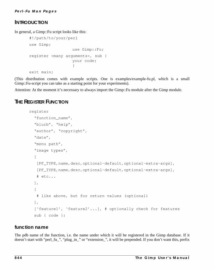
Pe r l - F u M a n Pa g e s
mall
.
. If itfix
INTRODUCTION
In general, a Gimp::Fu script looks like this:
#!/path/to/your/perl
use Gimp;use Gimp::Fu;
register <many arguments>, sub {your code;}
exit main;
(This distribution comes with example scripts. One is examples/example-fu.pl, which is a sGimp::Fu-script you can take as a starting point for your experiments).
Attention: At the moment it’s necessary to always import the Gimp::Fu module after the Gimp module
THE REGISTER FUNCTION
register
“function_name”,
“blurb”, “help”,
“author”, “copyright”,
“date”,
“menu path”,
“image types”,
[
[PF_TYPE,name,desc,optional-default,optional-extra-args],
[PF_TYPE,name,desc,optional-default,optional-extra-args],
# etc...
],
[
# like above, but for return values (optional)
],
[‘feature1’, ‘feature2’...], # optionally check for features
sub { code };
function nameThe pdb name of the function, i.e. the name under which it will be registered in the Gimp databasedoesn’t start with “perl_fu_”, “plug_in_” or “extension_”, it will be prepended. If you don’t want this, pre
8 4 4 T h e G i m p U s e r ’ s M a n u a l

A p p e n d i x D
the
ym-
agene.
st
d fore,
ablethe
g box as
don’t
your function name with a single “+”. The idea here is that every Gimp::Fu plug-in will be found undercommon perl_fu_–prefix.
blurbA small description of this script/plug-in.
helpA help text describing this script. Should be longer and more verbose than blurb.
copyrightThe copyright designation for this script. Important! Save your intellectual rights!
dateThe “last modified” time of this script. There is no strict syntax here, but I recommend ISO format (yyymdd or yyyy-mm-dd).
menu pathThe menu entry Gimp should create. It should start either with <Image>, if you want an entry in the immenu (the one that opens when clicking into an image), <Xtns>, for the Xtns menu or <None> for no
image typesThe types of images your script will accept. Examples are “RGB”, “RGB*”, “GRAY, RGB” etc... Moscripts will want to use “*”, meaning “any type.”
The Parameter ArrayAn array ref containing parameter definitions. These are similar to the parameter definitions usegimp_install_procedure, but include an additionaldefault value used when the caller doesn’t supply onand optional extra arguments describing some types like PF_SLIDER.
Each array element has the form [type, name, description, default_value, extra_args].
<Image>-type plug-ins get two additional parameters, image (PF_IMAGE) and draw(PF_DRAWABLE). Do not specify these yourself. Also, the run_mode argument is never given toscript, but its value can be accessed in the package-global $run_mode. The name is used in the dialoa hint, the description will be used as a tooltip.
See the section Parameter Types for the supported types.
The Return ValuesThis is just like the parameter array, just that it describes the return values. Of course, default valuesmake much sense here. (Even if they did, it’s not implemented anyway.) This argument is optional.
T h e G i m p U s e r ’ s M a n u a l 8 4 5

Pe r l - F u M a n Pa g e s
nt is
en themati-
pretedurn
reasonecifysyn-
tion
lebut-
n expla-escrip-
The Features RequirementsSee theGimp::Featuresman page for a description of which features can be checked for. This argumeoptional (but remember to specify an empty return value array, [], if you want to specify it).
The CodeThis is either an anonymous sub declaration (sub { your code here; }, or a coderef, which is called whscript is run. Arguments (including the image and drawable for <Image> plug-ins) are supplied autocally.
It is good practice to return an image, if the script creates one, or undef, since the return value is interby Gimp::Fu (like displaying the image or writing it to disk). If your script creates multiple pictures, retan array.
PARAMETER TYPES
PF_INT8, PF_INT16, PF_INT32, PF_INT, PF_FLOAT, PF_STRING, PF_VALUEAre all mapped to a string entry, since Perl doesn’t really distinguish between all these datatypes. Thethey exist is to help other scripts (possibly written in other languages! really!). It’s nice to be able to spa float as 13.45 instead of “13.45” in C! PF_VALUE is synonymous to PF_STRING, and <PF_INT> isonymous to <PF_INT32>.
PF_COLOR, PF_COLOURWill accept a color argument. In dialogs, a color preview will be created which will open a color selecbox when clicked.
PF_IMAGEA Gimp image.
PF_DRAWABLEA Gimp drawable (image, channel or layer).
PF_TOGGLE, PF_BOOLA boolean value (anything Perl would accept as true or false). The description will be used for the toggton label!
PF_SLIDERUses a horizontal scale. To set the range and stepsize, append an array ref (see Gtk::Adjustment for anation) [range_min, range_max, step_size, page_increment, page_size] as “extra argument” to the dtion array. Default values will be substitued for missing entries, like in:
[PF_SLIDER, "alpha value", "the alpha value", 100, [0, 255, 1] ]
8 4 6 T h e G i m p U s e r ’ s M a n u a l

A p p e n d i x D
will
acti-
peci-unc-e and
/pattern/
rence
pdated
en the
t not
PF_SPINNERThe same as PF_SLIDER, except that it uses a spinbutton instead of a scale.
PF_RADIOIn addition to a default value, an extra argument describing the various optionsmustbe provided. That extraargument must be a reference to an array filled with Option-Name = Option-Value> pairs. Gimp::Futhen generate a horizontal frame with radio buttons, one for each alternative. For example:
[PF_RADIO, "direction", "the direction to move to", 5,\[Left => 5, Right => 7]]]
draws two buttons, when the first (the default, “Left”) is activated, 5 will be returned. If the second isvated, 7 is returned.
PF_FONTLets the user select a font and returns an X Logical Font Descriptor (XLFD). The default argument, if sfied, must be a full XLFD specification, or a warning will be printed. Please note that the Gimp text ftions using these fontnames (gimp_text_..._fontname) ignore the size. You can extract the sizdimension by using the xlfd_size function.
In older Gimp-Versions a user-supplied string is returned.
PF_BRUSH, PF_PATTERN, PF_GRADIENTLets the user select a brush/pattern/gradient whose name is returned as a string. The default brushgradient–name can be preset.
PF_CUSTOMPF_CUSTOM is for those of you requiring some nonstandard-widget. You have to supply a code refereturning three values as the extra argument:
(widget, settor, gettor)
widget is Gtk widget that should be used.
settor is a function that takes a single argument, the new value for the widget (the widget should be uaccordingly).
gettor is a function that should return the current value of the widget.
While the values can be of any type (as long as it fits into a scalar), be prepared to get a string whscript is started from the commandline or the PDB.
PF_FILEThis represents a file system object. It usually is a file, but can be anything (directory, link). It migheven exist at all.
T h e G i m p U s e r ’ s M a n u a l 8 4 7
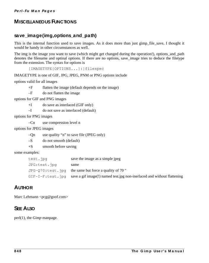
Pe r l - F u M a n Pa g e s
ght it
_pathfiletype
ing
MISCELLANEOUS FUNCTIONS
save_image(img,options_and_path)This is the internal function used to save images. As it does more than just gimp_file_save, I thouwould be handy in other circumstances as well.
The img is the image you want to save (which might get changed during the operation!), options_anddenotes the filename and optinal options. If there are no options, save_image tries to deduce thefrom the extension. The syntax for options is
[IMAGETYPE[OPTIONS...]:]filespec
IMAGETYPE is one of GIF, JPG, JPEG, PNM or PNG options include
options valid for all images
+F flatten the image (default depends on the image)
–F do not flatten the image
options for GIF and PNG images
+I do save as interlaced (GIF only)
–I do not save as interlaced (default)
options for PNG images
–Cn use compression level n
options for JPEG images
–Qn use quality “n” to save file (JPEG only)
–S do not smooth (default)
+S smooth before saving
some examples:
test.jpg save the image as a simple jpeg
JPG:test.jpg same
JPG–Q70:test.jpg the same but force a quality of 70 "
GIF–I–F:test.jpg save a gif image(!) named test.jpg non-inerlaced and without flatten
AUTHOR
Marc Lehmann <[email protected]>
SEE ALSO
perl(1), theGimp manpage.
8 4 8 T h e G i m p U s e r ’ s M a n u a l
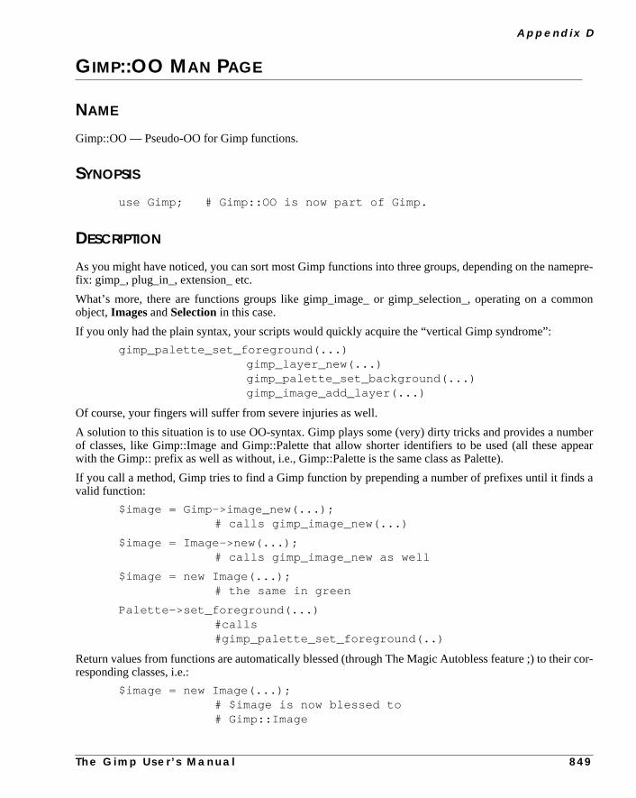
A p p e n d i x D
epre-
mmon
mberppear
s a
ir cor-
GIMP::OO MAN PAGE
NAME
Gimp::OO — Pseudo-OO for Gimp functions.
SYNOPSIS
use Gimp; # Gimp::OO is now part of Gimp.
DESCRIPTION
As you might have noticed, you can sort most Gimp functions into three groups, depending on the namfix: gimp_, plug_in_, extension_ etc.
What’s more, there are functions groups like gimp_image_ or gimp_selection_, operating on a coobject,Images andSelection in this case.
If you only had the plain syntax, your scripts would quickly acquire the “vertical Gimp syndrome”:
gimp_palette_set_foreground(...)gimp_layer_new(...)gimp_palette_set_background(...)gimp_image_add_layer(...)
Of course, your fingers will suffer from severe injuries as well.
A solution to this situation is to use OO-syntax. Gimp plays some (very) dirty tricks and provides a nuof classes, like Gimp::Image and Gimp::Palette that allow shorter identifiers to be used (all these awith the Gimp:: prefix as well as without, i.e., Gimp::Palette is the same class as Palette).
If you call a method, Gimp tries to find a Gimp function by prepending a number of prefixes until it findvalid function:
$image = Gimp->image_new(...);# calls gimp_image_new(...)
$image = Image->new(...);# calls gimp_image_new as well
$image = new Image(...);# the same in green
Palette->set_foreground(...)#calls#gimp_palette_set_foreground(..)
Return values from functions are automatically blessed (through The Magic Autobless feature ;) to theresponding classes, i.e.:
$image = new Image(...);# $image is now blessed to# Gimp::Image
T h e G i m p U s e r ’ s M a n u a l 8 4 9

Pe r l - F u M a n Pa g e s
, Gimp
are
wn as
$image->height;# calls gimp_image_height($image)
$image->flatten;# likewise gimp_flatten($image)
$image->histogram(...);# calls gimp_histogram($image, ...),# since gimp_image_histogram# does not exist
The class argument ($image in the above examples) is prepended to the argument list.
Another shortcut: Many functions want a (redundant) image argument, like:
$image–>shear ($layer, ...)
Because all you want is to shear the $layer, not the $image, this is confusing as well. In cases like thisallows you to write:
$layer–>shear (...)
and automatically infers the additional IMAGE-type argument.
As the (currently) last goodie, if the first argument is of type INT32, its name is “run_mode” and thereno other ambiguties, you can omit it, i.e. these three calls are equivalent:
plug_in_gauss_rle (RUN_NONINTERACTIVE, $image, $layer, 8, 1, 1);
plug_in_gauss_rle ($image, $layer, 8, 1, 1);
plug_in_gauss_rle ($layer, 8, 1, 1);
You can call all sorts of sensible and not-so-sensible functions, so this feature can be abused:
patterns_list Image; # will call gimp_patterns_list
quit Plugin; # will quit the Gimp, not an Plugin.
There is no image involved here whatsoever.
AVAILABLE CLASSES
The following classes (with and without Gimp::) are available. The prefixes that are checked are showell (the null prefix “” is implicit).
Gimp (there is no Gimp::Gimp, only Gimp::)gimp_
Layergimp_layer_
gimp_drawable_gimp_floating_sel_gimp_image_
8 5 0 T h e G i m p U s e r ’ s M a n u a l

A p p e n d i x D
gimp_plug_in_
Imagegimp_image_
gimp_drawable_gimp_plug_in_
Drawablegimp_drawable_
gimp_layer_gimp_image_gimp_plug_in_
Selectiongimp_selection_
Channelgimp_channel_
gimp_drawable_gimp_selection_gimp_image_gimp_plug_in_
Displaygimp_display_
gimp_
Palettegimp_palette_
Pluginplug_in_
Gradientsgimp_gradients_
T h e G i m p U s e r ’ s M a n u a l 8 5 1

Pe r l - F u M a n Pa g e s
Editgimp_edit_
Progressgimp_progress_
Region(none except the implicit null prefix)
Tilegimp_tile_
PixelRgngimp_pixel_rgn_
GDrawablegimp_gdrawable_
Brushesgimp_brushes_
Parasiteparasite_
gimp_
AUTHOR
Marc Lehmann <[email protected]>
SEE ALSO
perl(1), theGimp manpage.
8 5 2 T h e G i m p U s e r ’ s M a n u a l
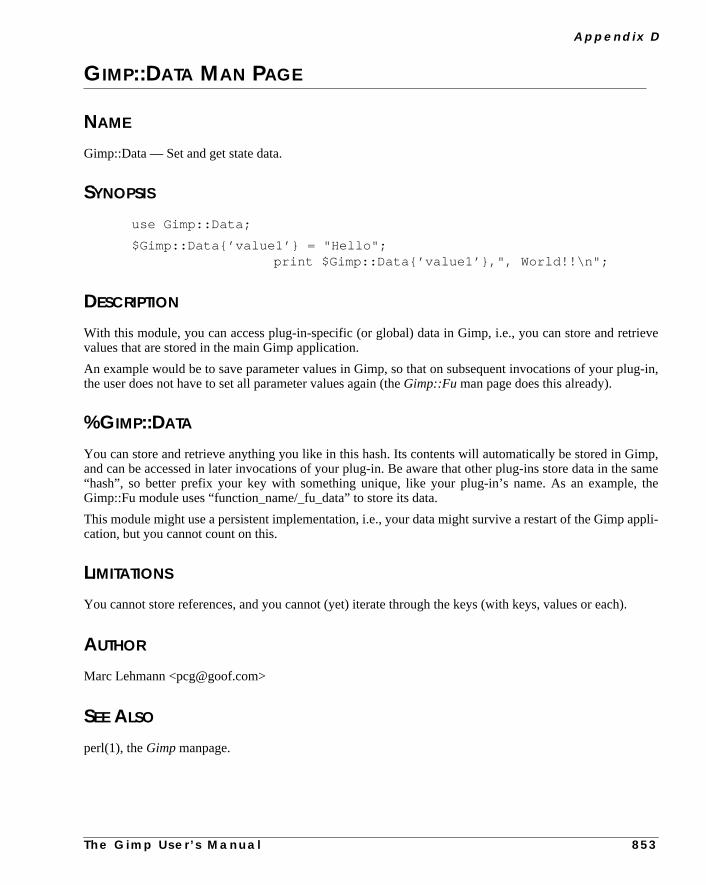
A p p e n d i x D
trieve
lug-in,
imp,e same, the
appli-
h).
GIMP::DATA MAN PAGE
NAME
Gimp::Data — Set and get state data.
SYNOPSIS
use Gimp::Data;
$Gimp::Data{’value1’} = "Hello";print $Gimp::Data{’value1’},", World!!\n";
DESCRIPTION
With this module, you can access plug-in-specific (or global) data in Gimp, i.e., you can store and revalues that are stored in the main Gimp application.
An example would be to save parameter values in Gimp, so that on subsequent invocations of your pthe user does not have to set all parameter values again (theGimp::Fu man page does this already).
%GIMP::DATA
You can store and retrieve anything you like in this hash. Its contents will automatically be stored in Gand can be accessed in later invocations of your plug-in. Be aware that other plug-ins store data in th“hash”, so better prefix your key with something unique, like your plug-in’s name. As an exampleGimp::Fu module uses “function_name/_fu_data” to store its data.
This module might use a persistent implementation, i.e., your data might survive a restart of the Gimpcation, but you cannot count on this.
LIMITATIONS
You cannot store references, and you cannot (yet) iterate through the keys (with keys, values or eac
AUTHOR
Marc Lehmann <[email protected]>
SEE ALSO
perl(1), theGimp manpage.
T h e G i m p U s e r ’ s M a n u a l 8 5 3

Pe r l - F u M a n Pa g e s
ne, it
ort off the
hed toem. So
) func-
, back-. This isre.
8 5 4 T h e G i m p U s e r ’ s M a n u a l
GIMP::UTIL MAN PAGE
NAME
Gimp::Util — some handy routines for Gimp-Perl users
SYNOPSIS
use Gimp;use Gimp::Util;
DESCRIPTION
Gimp-Perl is nice, but when you have to write 10 lines every time just to get some simple functions dovery quickly becomes tedious :-/
This module tries to define some functions that aim to automate frequently used tasks, i.e. it’s a scatchall–bag for (possibly) useful macro functions. If you want to add a function just mail the author oGimpPerl extension (see below).
In Gimp–Perl (but not in Gimp as seen by the end user) it is possible to have layers that are NOT attacan image. This is, IMHO a bad idea, you end up with them and the user cannot see them or delete thwe always attach our created layers to an image here, to avoid memory leaks and debugging times.
These functions try to preserve the current settings like colors, but not all do.
Also: These functions are handled in exactly the same way as PDB-Functions, i.e., the (hypotheticaltion gimp_image_xyzzy can be called as $image–>xyzzy, if the module is available.
The need to explicitly use Gimp::Util will go away in the future.
FUNCTIONS
get_state (), set_state stateget_state returns a scalar representing most of Gimp’s global state (at the moment foreground colorground color, active gradient, pattern and brush). The state can later be restored by a call to set_stateideal for library functions such as the ones used here, at least when it includes more state in the futu
layer_create image, name, color, posCreates a colored layer, insert into image and return layer.
text_draw imag, layer, text, font, size, fgcolorCreates a colored text, draw over a background, add to img, ret img.

A p p e n d i x D
eeded
or not.
wither
isible
xten-
T h e G i m p U s e r ’ s M a n u a l 8 5 5
image_create_text text, font, size, fgcolor, bgcolorCreates an image, add colored text layer on a background layer, return img.
layer_add_layer_as_mask image, layer, layermaskTakes a layer and add it as a mask to another layer, return mask.
gimp_text_wh $text, $fontnameReturns the width and height of the “$text” of the given font (XLFD format)
gimp_drawable_mask $drawableReturns an array (x,y,w,h) containing the upper-left corner and the size of the current mask, just as nby pixelrgn and similar functions.
gimp_image_layertype $alphaReturns the corresponding layer type for an image, alpha controls whether the layer type is with alphaExample: imagetype: RGB -> RGB_IMAGE (or RGBA_IMAGE).
gimp_image_add_new_layer $image, $index, $fill_type, $alphaCreates a new layer and adds it at position $index (default 0) to the image, after filling itgimp_drawable_fill $fill_type (default BG_IMAGE_FILL). If $alpha is non-zero (default 1), the new layhas alpha.
gimp_image_set_visible $image, @layers,gimp_image_set_invisible $image,@layers mark the given layers visible (invisible) and all others inv(visible).
gimp_layer_get_position $layerReturns the position the layer has in the image layer stack.
gimp_layer_set_position $layer, $new_indexMoves the layer to a new position in the layer stack.
AUTHOR
Various, version 1.000 written mainly by Tels (http://bloodgate.com/). The author of the Gimp–Perl esion (contact him to include new functions) is Marc Lehmann <[email protected]>

Pe r l - F u M a n Pa g e s
this isout
w-amedon rawt it with
do this
hav-
ent,
le, by
GIMP::PIXEL MAN PAGE
NAME
Gimp::Pixel — how to operate on raw pixels
SYNOPSIS
use Gimp;
use Gimp::PDL; # you need Gimp::PDL for pixel access
use PDL; # to make sensible things with the pixels
# Gimp::GDrawable – The GDrawable structure
# Gimp::Tile – The Tile family of functions.
# Gimp::PixelRgn – The PixelRgn family of functions.
DESCRIPTION
You can access the pixels in a drawable through tiles or pixel regions. This man page explains howdone in Perl. All classes (Gimp::GDrawable, Gimp::Tile, Gimp::PixelRgn) are available with and withthe Gimp:: prefix.
GDRAWABLES
Well, you know drawables (also known as PARAM_DRAWABLE or Gimp::Drawable)? In Gimp, draables are things you can draw on: layers, channels or whole images. While most functions ngimp_drawable_something operate on drawable_IDs, some functions (notably the ones operatingpixel data!) need a GDrawable instead. Every drawable has a corresponding GDrawable; you can gethe gimp_drawable_get function:
my $gdrawable = $drawable–>get;
When the $gdrawable is destroyed, it is automatically flushed and detached, so you don’t need toyourself.
TILES
Tiles are the basic building blocks of all drawables. Each drawable consists of a “grid” of tiles, each tileing the same size. The size of a tile is always the same (it’s hardcoded in your Gimp program).
The gimp_tile_width and gimp_tile_height functions return the current width/height of a tile (at the momthis is 64x64).
How do I get a tile? First, you have to grab a GDrawable structure. You can get one from any drawabcalling the get function:
my $gdrawable = $drawable–>get;
8 5 6 T h e G i m p U s e r ’ s M a n u a l

A p p e n d i x D
imagele gets
e tile,
rectan-m too
any
-
in ans,
In a sense, <$gdrawable> contains all tiles. Changes you make to them might not be reflected in theuntil you destroy this variable. (Thats the reason I used “my” in the above example. Once $gdrawabout of scope, the drawable in the Gimp automatically gets updated).
To get access to a tile, you have to call get_tile or get_tile2. get_tile expects row/column numbers of thwhile get_tile2 expects pixel coordinates and will return the tile that pixel is in:
my $tile = $gdrawable–>get_tile2(1,75,60);
The data method returns and sets the raw pixel data.
$piddle = $tile–>data; # get the tile data as a piddle
$piddle *= 0.5; # do sth. with the pixels
$tile–>data($piddle); # and modify the tile
PIXELREGIONS
PixelRegions are rectangular parts of a drawable. You can access single pixels, rows, columns andgles within these regions. Don’t expect me to explain everything now, I don’t understand the mechaniswell myself.
How do I create a pixel region? First, you have to grab a GDrawable structure. You can get one fromdrawable, by calling the get function:
my $gdrawable = $drawable–>get;
Now, you can create as many PixelRgn structures as you want from the GDrawable:
my $region = new PixelRgn($gdrawable,0,0,50,30,1,0); # with "new”
my $region = $gdrawable–>pixel_rgn(0,0,50,30,1,0);#or from a \ #drawable
Which method you choose is purely a question of style...
The following functions return packed pixel data (see theGimp::PDLman page for an easier way to manipulate on image data):
$piddle = $region–>get_pixel(45,60);#return the pixel at (45|60)
$piddle = $region–>get_row(45,60,10);#return ten horizontal pixels
$piddle = $region–>get_col(45,60,10);#same but vertically
$piddle = $region–>get_rect(45,60,10,12);#a 10x12 rectangle
To modify pixels, the dirty bit of the region must be set (I believe, but I don’t see what the dirty bitregion is for, so I might be wrong), and you can write pixel data to the region with the following functioeach one corresponding to a get-function:
$region–>set_pixel($piddle,45,60);# set pixel at (45|60)
$region–>set_row($piddle,45,60);# set a row "
T h e G i m p U s e r ’ s M a n u a l 8 5 7

Pe r l - F u M a n Pa g e s
g; they
nc-
, then
nction
$region–>set_col($piddle,45,60);# set a column
$region–>set_rect($piddle,45,60);# set a whole rectangle
Please note that (unlike the C functions they call), the size arguments (width and/or height) are missincan be calculated from the piddle.
AUTHOR
Marc Lehmann <[email protected]>
SEE ALSO
perl(1), Gimp(1).
GIMP::COMPAT MAN PAGE
NAME
Gimp::Compat — compatibility functions for older versions of Gimp.
SYNOPSIS
<loaded automatically on demand>
DESCRIPTION
Older versions of Gimp (version 1.0 at the time of this writing) lack some very important or useful futions.
This module is providing the most needed replacement functions. If you happen to miss a functionplease create a replacement function and send it to me ;)
These functions are handled in exactly the same way as PDB-Functions, i.e., the (hypothetical) fugimp_image_xyzzy can be called as $image->xyzzy, if the module is available.
FUNCTIONS
gimp_text_fontname, gimp_get_extents_fontnameThese are emulated in 1.0.
8 5 8 T h e G i m p U s e r ’ s M a n u a l
A p p e n d i x D
ntact
ing theime, the
gimp_paintbrushThe last two arguments only available in 1.1 are simply dropped.
AUTHOR
Various, Dov Grobgeld <[email protected]>. The author of the Gimp-Perl extension (cohim to include new functions) is Marc Lehmann <[email protected]>
GIMP::FEATURE MAN PAGE
NAME
Gimp::Features — check for specific features to be present before registering the script.
SYNOPSIS
use Gimp::Features;
or
use Gimp::Features qw(feature1 feature2 ...);
DESCRIPTION
This module can be used to check for specific features to be present. This can be used to deny runnscript when neccessary features are not present. While some features can be checked for at any tGimp::Fu module offers a nicer way to check for them.
gtkChecks for the presence of the gtk interface module.
gtk–1.1, gtk–1.2Checks for the presence of gtk–1.1 (1.2) or higher.
perl–5.005Checks for Perl version 5.005 or higher.
pdlChecks for the presence of a suitable version of PDL (>=1.9906).
T h e G i m p U s e r ’ s M a n u a l 8 5 9

Pe r l - F u M a n Pa g e s
except
).
resent,
ng anis fea-
her be
s fea-
gnomeChecks for the presence of the Gnome-Perl module.
gtkxmhtlChecks for the presence of the Gtk::XmHTML module.
unixChecks whether the script runs on a unix-like operating system. At the moment, this is every systemwindows, macos, os2 and vms.
gimp–1.1, gimp–1.2Checks for the presense of Gimp in at least version 1.1 (1.2).
This feature can only be checkedafter Gimpmain> has been called (usually found in the form exit mainSee theGimp::Fu man page on how to check for these.
FUNCTIONS
present(feature)Checks for the presense of the single feature given as the argument. Returns true if the feature is pfalse otherwise.
need(feature,[function–name])Requires a specific feature. If the required feature is not present, the program will exit gracefully, loggiappropriate message. You can optionally supply a function name to further specify the place where thture was missing.
This is the function used when importing symbols from the module.
missing(feature–description,[function–name])Indicates that a generic feature (described by the first argument) is missing. A function name can furtspecified. This function will log the given message and exit gracefully.
describe(feature)Returns a string describing the given feature in more detail, or undef if there is no description for thiture.
list()Returns a list of features that can be checked for. This list might not be complete.
8 6 0 T h e G i m p U s e r ’ s M a n u a l
A p p e n d i x D
nfig-values
AUTHOR
Marc Lehmann <[email protected]>
SEE ALSO
perl(1), Gimp(1).
GIMP::CONFIG MAN PAGE
NAME
Gimp::Config — config options found during configure time.
DESCRIPTION
The Gimp::Config module creates a tied hash %Gimp::Config which contains all the definitions the coure script and Perl deduced from the system configuration at configure time. You can access thesejust like you access any other values, i.e., $Gimp::Config{KEY}. Some important keys are:
IN_GIMP => true when Gimp-Perl was part of the Gimp distribution.
GIMP => the path of the Gimp executable
prefix => the installation prefix
libdir => the Gimp system-wide libdir
bindir => paths where Gimp binaries are installed
gimpplugindir => the Gimp plug-in directory (without the /plug-ins–suffix)
SEE ALSO
TheGimp man page.
GIMP::POD MAN PAGE
NAME
Gimp::Pod — Evaluate pod documentation embedded in scripts.
SYNOPSIS
use Gimp::Pod;
$pod = new Gimp::Pod;
T h e G i m p U s e r ’ s M a n u a l 8 6 1
Pe r l - F u M a n Pa g e s
At the.
found.
string,
$text = $pod–>format ();
$html = $pod–>format (’html’);
$synopsis = $pod–>section (’SYNOPSIS’);
$author = $pod–>author;
@sections = $pod–>sections;
DESCRIPTION
Gimp::Pod can be used to find and parse embedded pod documentation in Gimp-Perl scripts.moment, only the formatted text can be fetched; future versions might have more interesting features
METHODS
newReturns a new Gimp::Pod object representing the current script or undef, if an error occurred.
format([$format])Returns the embedded pod documentation in the given format, or undef if no documentation can beFormat can be one of ‘text’, ‘html’, ‘man’ or ‘latex’. If none is specified, ’text’ is assumed.
section($header)Tries to retrieve the section with the header $header. There is no trailing newline on the returnedwhich may be undef in case the section can’t be found.
copyrightTries to retrieve fields suitable for calls to the register function.
sectionsReturns a list of paragraphs found in the pod.
AUTHOR
Marc Lehmann <[email protected]>
SEE ALSO
perl(1), Gimp(1),
8 6 2 T h e G i m p U s e r ’ s M a n u a l

A p p e n d i x D
Perl-, thisrver>
Perl
canriablerd is
cks,
to use.for a
GIMP::NET MAN PAGE
NAME
Gimp::Net — Communication module for the Gimp–Perl server.
SYNOPSIS
use Gimp;
DESCRIPTION
For Gimp::Net (and thus commandline and remote scripts) to work, you first have to install the “Server” extension somewhere where Gimp can find it (e.g.,, in your .gimp/plug-ins/ directory). Usuallyis done automatically while installing the Gimp extension. If you have a menu entry C<<Xtns>/Perl-Sethen it is probably installed.
The Perl Server can either be started from the C<<Xtns>> menu in Gimp, or automatically when ascript can’t find a running Perl Server.
When started from within Gimp, the Perl-Server will create a unix domain socket to which local clientsconnect. If an authorization password is given to the Perl Server (by defining the environment vaGIMP_HOST before starting Gimp), it will also listen on a tcp port (default 10009). Since the passwotransmitted in cleartext, using the Perl-Server over tcp effectivelylowers the security of your network tothe level of telnet. Even worse: The current Gimp::Netprotocol can be used for denial of service attai.e., crashing the Perl Server. There also *might* be buffer overflows.
ENVIRONMENT
The environment variable GIMP_HOST specifies the default server to contact and/or the passwordThe syntax is [auth@][tcp/]hostname[:port] for tcp, [auth@]unix/local/socket/path for unix and spawn/private gimp instance. Examples are:
www.yahoo.com # just kidding ;)"
yahoo.com:11100 # non–standard port "
tcp/yahoo.com # make sure it uses tcp
authorize@tcp/yahoo.com:123 # full–fledged specification "
unix/tmp/unx # use unix domain socket "
password@unix/tmp/test # additionally use a password "
authorize@ # specify authorization only "
spawn/ # use a private gimp instance "
spawn/nodata # pass ––no–data switch "
spawn/gui # don’t pass –n switch
T h e G i m p U s e r ’ s M a n u a l 8 6 3

Pe r l - F u M a n Pa g e s
e the
ned by
ould
CALLBACKS
net()Is called after you have succesfully connected to the server. Do your dirty work in this function, or seGimp::Fu man page for a better solution.
FUNCTIONS
server_quit()Sends the Perl Server a quit command.
get_connection()Return a connection id which uniquely identifies the current connection.
set_connection(conn_id)Set the connection to use on subsequent commands. conn_id is the connection id as returget_connection( ).
BUGS
(Ver 0.04) This module is much faster than it was thought to be... Silly that I wondered whether I shimplement it in Perl or C, since Perl is so fast.
AUTHOR
Marc Lehmann <[email protected]>
SEE ALSO
perl(1), theGimp manpage.
21/May/99 Perl 5.004, patch 04 1
GIMP::LIB MAN PAGE
NAME
Gimp::Lib — Interface to libgimp (as opposed to Gimp::Net)
8 6 4 T h e G i m p U s e r ’ s M a n u a l

A p p e n d i x D
with”.
ase
andhere is
SYNOPSIS
use Gimp; # internal use only
DESCRIPTION
This is the package that interfaces to Gimp via the libgimp interface, i.e., the normal interface to useGimp. You don’t normally use this module directly, look at the documentation for the package “Gimp
AUTHOR
Marc Lehmann <[email protected]>
SEE ALSO
perl(1), theGimp man page.
GIMP::PDL MAN PAGE
NAME
Gimp::PDL — Overwrite Tile/Region functions to work with piddles. This module is obsolete, pleremove any references to it.
SYNOPSIS
use Gimp;use Gimp::PDL;use PDL;
DESCRIPTION
This module overwrites some methods of Gimp::Tile and Gimp::PixelRgn. The new functions returnaccept piddles. The last argument (height) of gimp_pixel_rgn_set_rect is calculated from the piddle. Tno other way to access the raw pixeldata in Gimp.
Some examples:
$region = $drawable–>get–>pixel_rgn (0,0, 100,100, 1,0);
$pixel = $region–>get_pixel (5,7);# fetches the pixel from (5|7)
print $pixel; " "# outputs something like
T h e G i m p U s e r ’ s M a n u a l 8 6 5

Pe r l - F u M a n Pa g e s
# [255, 127, 0], i.e. in
# RGB format ;)
$region–>set_pixel ($pixel * 0.5, 5, 7);# darken the pixel
$rect = $region–>get_rect (3,3,70,20);# get a horizontal stripe "
$rect = $rect–>hclip(255/5)*5;# clip and multiply by 5
$region–>set_rect($rect); " "# and draw it! "
undef $region; " "# and update it!
AUTHOR
Marc Lehmann <[email protected]>
SEE ALSO
TheGimp::Pixel man page, perl(1), Gimp(1).
This module is obsolete, please remove any references to it.
GIMP::UI MAN PAGE
NAME
Gimp::UI — “simulation of libgimpui”, and more!
SYNOPSIS
use Gimp::UI;
DESCRIPTION
Due to the brain-damaged (read: “unusable”) libgimpui API, I had to reimplement all of it in Perl.
$option_menu = new Gimp::UI::ImageMenu
$option_menu = new Gimp::UI::LayerMenu
$option_menu = new Gimp::UI::ChannelMenu
8 6 6 T h e G i m p U s e r ’ s M a n u a l

A p p e n d i x D
geld
$option_menu = new Gimp::UI::DrawableMenu \(constraint_func, active_element, \var);
$button = new Gimp::UI::PatternSelect;
$button = new Gimp::UI::BrushSelect;
$button = new Gimp::UI::GradientSelect;
$button = new Gimp::UI::ColorSelectButton;
AUTHOR
Marc Lehmann <[email protected]>. The ColorSelectButton code is written by Dov Grob<[email protected]>, with modifications by Kenneth Albanowski <[email protected]>.
SEE ALSO
perl(1), theGimp man page.
T h e G i m p U s e r ’ s M a n u a l 8 6 7

A P P E N D I X E
Sane-Supported ScannersThis appendix provides a list of scanners supportedby Sane 1.0.1.

S a n e - S u p p o r t e d S c a n n e r s
LEGEND
You need to enable this backend in Sanesdll.conf (in thesane config directory). Otherwise, Sanewill not enable your scanner.
There are four types of status:
• Stable: This is proven and works well if it’s supported.
• Beta: Usually works just fine but it can sometimes hit a bug.
• Alpha: This may work but it needs more development and debugging.
• New: This package is so new that it doesn’t have a qualified status.
The comments column often indicates how well the backend works. (It can be wise to runfind-scannerto find out more about the notes.)
Manufacturer Model Backend Status Comment
Abaton Scan 300/GS abaton alpha All known modes and functionssupported
Scan 300/S abaton alpha Untested, use with caution
AGFA Focus GS agfafocus alpha 6 bit gray
Focus Lineart agfafocus alpha Lineart only? Untested
Focus II agfafocus alpha Gray only
Focus Color agfafocus alpha
Focus Color Plus agfafocus alpha 3-pass
Arcus II microtek beta Arcus *II*, not Arcus!
StudioScan II microtek beta Not quite functional yet
StudioScan IIsi microtek beta Not quite functional yet
SnapScan 300 SnapScan alpha Only 8 bits/sample
SnapScan 310 SnapScan alpha Only 8 bits/sample
SnapScan 600 SnapScan alpha Only 8 bits/sample
SnapScan 1236s SnapScan alpha Only 8 bits/sample
Apple Apple Scanner apple alpha 4 bit, 16 shades of gray
OneScanner apple alpha 8 bit, 256 shades of gray; backendneeds more work
ColorOneScanner apple alpha Only non-color modes
Artec/Ultima AT3 artec alpha Works (developer’s own model)
A6000C artec alpha Very alpha
A6000C PLUS artec alpha Testing in progress
AT6 artec alpha Testing in progress
AT12 artec alpha Testing in progress
BlackWidow BW4800SP artec alpha Rebadged Artec AT3
Canon CanoScan 300 canon alpha 1 pass; flatbed scanner
CanoScan 600 canon alpha 1 pass; flatbed scanner
CanoScan 2700F canon alpha 1 pass; film scanner
Escom Image Scanner 256 umax stable SCSI-ID=UMAX UG 80
8 7 0 T h e G i m p U s e r ’ s M a n u a l

A p p e n d i x E
Epson GT-5500 epson ? OK
GT-7000 epson ? OK
HP HP ScanJet Plus hp alpha
HP ScanJet IIc hp alpha
HP ScanJet IIp hp alpha
HP ScanJet IIcx hp alpha
HP ScanJet 3c hp alpha
HP ScanJet 4c hp alpha
HP ScanJet 6100C hp alpha
HP ScanJet 3p hp alpha
HP ScanJet 4p hp alpha
HP ScanJet 5p hp alpha
HP ScanJet 6200C hp alpha
HP ScanJet 6250C hp alpha
HP PhotoSmartPhotoScanner
hp alpha
Kodak DC20 dc25 alpha DC-20 is untested!
DC25 dc25 alpha
DC210 dc210 alpha
Linotype Hell Jade umax stable SCSI-ID=LinoHell Office
Jade2 umax stable SCSI-ID=LinoHell Office2
Saphir umax stable Not tested
Saphir2 umax stable SCSI-ID=LinoHell SAPHIR2
Saphir Ultra umax stable Not tested
Saphir Ultra II umax stable Not tested
Saphir HiRes umax stable Not tested
Opal umax stable Not tested
Opal Ultra umax stable Not tested
Microtek ScanMaker E6 microtek beta
ScanMaker E3 microtek beta
ScanMaker E2 microtek beta 3-pass
ScanMaker 35t+ microtek beta Slide-scanner
ScanMaker III microtek beta
ScanMaker IISP microtek beta
ScanMaker IIHR microtek beta 3-pass
ScanMaker IIG microtek beta Gray only
ScanMaker II microtek beta 3-pass
ScanMaker600Z(S)
microtek beta Untested
ScanMaker600G(S)
microtek beta Gray only
Manufacturer Model Backend Status Comment
T h e G i m p U s e r ’ s M a n u a l 8 7 1

S a n e - S u p p o r t e d S c a n n e r s
ScanMaker V300 microtek2 alpha
ScanMaker V310 microtek2 alpha
ScanMaker V600 microtek2 alpha
ScanMaker E3plus microtek2 alpha
ScanMaker X6 microtek2 alpha
ScanMaker X6EL microtek2 alpha
ScanMaker 330 microtek2 alpha
ScanMaker 630 microtek2 alpha
ScanMaker 636 microtek2 alpha
ScanMaker9600XL
microtek2 alpha Only flatbed mode (?)
Phantom 636 microtek2 alpha
Mustek MFC-600S mustek beta 1 pass; (f/w >= 1.01; scsi id MFC-06000CZ)
MFC-600CD mustek beta 1 pass; (f/w >= 2.03; scsi id MFC-06000CZ)
MFS-6000CX mustek beta 3 pass; (f/w >= 2.71; scsi id MSF-06000CX
MSF-6000SP mustek beta 1 pass; (f/w >= 3.12; scsi id MSF-06000SP)
MFS-8000SP mustek beta 1 pass; (f/w >= 2.05; scsi id MSF-08000SP) lineart drops lines?
MFC-800S mustek beta 1 pass; (f/w == 1.06; scsi id MFC-08000CZ) color fails?
MFS-1200SP mustek beta 1 pass; (f/w == 1.00; scsi id MSF-12000SP)
MFS-1200SP mustek beta 1 pass; (f/w == 1.07; scsi id MFS-12000SP)
MFS-1200SP mustek beta 1 pass; (f/w == 1.02; scsi id MFS-12000SP) color fails?
MFS-12000CX mustek beta 3 pass; (f/w == 2.71; scsi id MFS-12000CX)
SE-6000SP beta 1 pass; (f/w == ? ; scsi id C03S10IDW)
SE-12000SP beta 1 pass; (f/w == 1.01; scsi id C06S12IDW)
Nikon LS-20 coolscan beta LS-30 is not supported
LS-1000 coolscan beta Doesn’t support gamma correction
AX-210 umax stable
Polaroid DMC dmc stable
Plustek Plustek 4830 plustek beta
Qtronix Sagitta Gray sagitta alpha No monocrome-mode at the moment
Manufacturer Model Backend Status Comment
8 7 2 T h e G i m p U s e r ’ s M a n u a l

A p p e n d i x E
ess
ss
SHARP JX-610 sharp new Preview/Color Lineart/Lineart/Threshold does not work
JX-250 sharp new Color Lineart does not give usefuloutput
JX-330 sharp new Not tested
Siemens S9036 agfafocus alpha Gray only
ST400 st400 alpha 6 bit gray
Tamarack Artiscan 6000C tamarack beta 3 pass, 300 DPI; please report succto [email protected]
Artiscan 8000C tamarack beta 3 pass, 400 DPI; please report succeto [email protected]
Artiscan 12000C tamarack beta 3 pass, 600 DPI
UMAX Vista S6 umax stable
Vista S6E umax stable
UMAX S-6E umax stable
UMAX S-6EG umax stable
Vista-S8 umax stable Not tested
Supervista S-1 umax stable
UMAX S-12 umax stable
UMAX S-12G umax stable
Astra 600S umax stable
Astra 610S umax stable
Astra 1200S umax stable
Astra 1220S umax stable
UC 630 umax stable Version 1.6 OK, others only lineart OK
UG 630 umax stable
UG 80 umax stable
UC 840 umax stable Version 1.6 OK, others only lineart OK
UC 1260 umax stable Version 1.6 OK, others unknown
Mirage umax stable Not tested
Mirage II umax stable Not tested
Mirage IIse umax stable Not tested
Vista-T630 umax stable OK for some firmware versions; onothers only lineart
PSD umax stable
PowerLook umax stable Not tested
PL-III umax stable Only works with some scanners(unknown why)
PowerLook III umax stable Not tested
PowerLook 2000 umax stable Not tested
PowerLook 3000 umax stable Not tested
Gemini D-16 umax stable
Manufacturer Model Backend Status Comment
T h e G i m p U s e r ’ s M a n u a l 8 7 3

S a n e - S u p p o r t e d S c a n n e r s
Vobis HighScan microtek2 alpha Only E3plus-based models
Vobis/Highscree ScanboostarPremium
umax stable OK, SCSI-ID=LinoHell Office2
Vuego 310S SnapScan alpha Close SnapScan 310-compatible
Manufacturer Model Backend Status Comment
8 7 4 T h e G i m p U s e r ’ s M a n u a l


A P P E N D I X F
Links And ReferencesIn this appendix, you will find all kinds of Gimp-related links. You will also find some bibliographiclinks to useful books, or books that we use at Frozen-river.

L i n k s A n d R e f e r e n c e s
LINKS
Web
IRC (dev chat) channel #Gimp
Resource URL
The one and only Gimp.org http://www.gimp.org
Latest Gimp news http://xach.dorknet.com/gimp/news/index.html
Plug-in registry to the latest plug-ins available for Gimp; you canalso upload your own plug-ins here
http://registry.gimp.org
Gimp FAQs http://www.rru.com/~meo/gimp
GUM http://manual.gimp.org
Scripts http://www.gimp.org/scripts.html
Server Port Location
irc.mint.net / irc.gimp.org 6666 Maine, USA
irc.canweb.net 6667 Toronto, Canada
irc.canberra.edu.au 6666 Canberra, Australia
irc.giblets.com 6667 Texas, USA
dazed.nol.net 6667 Texas, USA
irc.eanut.org 6667 Texas, USA
pandora.hrz.uni-bielefeld.de 6667 Germany
irc.chillin.org 6666 Florida, USA
irc.coherent.net 6667 Chicago, USA
irc.olg.com 6667 Maryland, USA
8 7 8 T h e G i m p U s e r ’ s M a n u a l

A p p e n d i x F
Books
Title ISBN
Photoshop Web Techniques 1-56205-733-2
Preparing Digital Images for Print 0-07-882146-0
Photoshop WOW Book 0-201-88370-8
Desktop Scanners 0-13-080904-7
Looking Good in Print 1-56604-856-7
List Address
gimp-developer information at:www.gimp.org/mailing_list.html
to subscribe or send mail to:“[email protected]”and put“subscribe gimp-developer [email protected]” in the body
gimp-user info at:www.gimp.org/mailing_list.html
to subscribe send mail to:“[email protected]”and put“subscribe gimp-user [email protected]” in the body
gimp-announce info at:www.gimp.org/mailing_list.html
to subscribe send mail to:“[email protected]”and put“subscribe gimp-announce you [email protected]” in the body
Japanese Gimpmailing list
info at:www.gimp.org/mailing_list.html
to subscribe send mail to:“[email protected]”
Hungarian Gimpmailing list
info at:www.gimp.org/mailing_list.html
to subscribe send mail to:[email protected] “SUBSCRIBE GIMP YOURNAME” as the subjectwhere your name is [email protected]
T h e G i m p U s e r ’ s M a n u a l 8 7 9

L i n k s A n d R e f e r e n c e s
FTPThe main FTP site isftp.gimp.org , but try to use a mirror near you.
Location URL
Africa ftp://ftp.is.co.za/applications/gimp/
Australia ftp://gimp.zeta.org.au/
ftp://ftp.au.gimp.org/pub/gimp/
ftp://ftp.progsoc.uts.edu.au/pub/
Austria ftp://gd.tuwien.ac.at/graphics/gimp/
Belgium ftp://gimp.rug.ac.be/pub/gimp/
Croatia ftp://ftp.linux.hr/pub/gnome/
Finland ftp://ftp.funet.fi/pub/sci/graphics/packages/gimp
France ftp://stef.u-picardie.fr/mirror/ftp.gimp.org/
ftp://ftp.minet.net/pub/gimp/
Germany ftp://infosoc.uni-koeln.de/pub/ftp.gimp.org/
ftp://ftp.tuts.net/mirror/gimp.org/
ftp://ftp.fh-heilbronn.de/mirrors/ftp.gimp.org/
Greece ftp://sunsite.ics.forth.gr/sunsite/pub/gimp/
Japan ftp://SunSITE.sut.ac.jp/pub/archives/packages/gimp/
ftp://ftp.u-aizu.ac.jp/pub/graphics/tools/gimp/
ftp://ring.nacsis.ac.jp/pub/graphics/gimp/
ftp://ring.aist.go.jp/pub/graphics/gimp/
ftp://ring.asahi-net.or.jp/pub/graphics/gimp/
ftp://ring.so-net.ne.jp/pub/graphics/gimp/
ftp://mirror.nucba.ac.jp/mirror/gimp
Korea ftp://ftp.kreonet.re.kr/pub/tools/X11/ftp.gimp.org/
Poland ftp://ftp.tuniv.szczecin.pl/pub/Linux/gimp
ftp://sunsite.icm.edu.pl/pub/graphics/gimp
Romania ftp://ftp.kappa.ro/pub/mirrors/mirrors-2/ftp.gimp.org/
Sweden ftp://ftp.acc.umu.se/pub/gimp
ftp://ftp.sunet.se/pub/gnu/gimp/
Taiwan ftp://linux.cis.nctu.edu.tw/pub/packages/X/gimp/
Turkey ftp://ftp.hun.edu.tr/pub/linux/gimp
UnitedKingdom
ftp://ftp.flirble.org/pub/X/gimp/
ftp://ftp.lmh.ox.ac.uk/pub/linux/
8 8 0 T h e G i m p U s e r ’ s M a n u a l

A p p e n d i x F
Perl-Fu
Sane
Xinput
ftp://unix.hensa.ac.uk/mirrors/ftp.gimp.org/pub/gimp/
United States ftp://ftp.insync.net/pub/mirrors/ftp.gimp.org/
ftp://ftp.cs.umn.edu/pub/gimp/
ftp://froody.res.cmu.edu/pub/gimp/
ftp://gimp.cs.stevens-tech.edu/mirrors/gimp/
ftp://ftp.ameth.org/pub/mirrors/ftp.gimp.org/
What URL
Perl-Fu Home Page http://gimp.pages.de
GTK Perl Module ftp://ftp.gtk.org/pub/gtk/perl/
Perl http://www.perl.com
Program URL
Sane home page http://www.mostng.com/sane
Sane program download ftp://ftp.mostang.com/pub/sane
Xsane home page http://www.wolfsburg.de/~rauch/sane/sane-xsane.html
Xsane download See Xsane home page
Solaris SCSI drivers ftp://ftp.fokus.gmd.de/pub/unix/kernel/scg/
Linux SCSI How-to http://metalab.unc.edu/LDP/HOWTO/HOWTO-INDEX-3.html#ss3.1
What URL
XFree86 home page http://www.xfree86.org
Xinput home page http://lepied.com/xfree86/
Percompiled/Linux XinputIntous drivers
http://www.levien.com/free/linux_intuos.html
Xinput how-to http://www.gtk.org/~otaylor/xinput/howto/index.html
Gimp Xinput patch http://www.gtk.org/~otaylor/xinput/patches.html
Location URL
T h e G i m p U s e r ’ s M a n u a l 8 8 1


I N D E X
Numerics4-color 1938-bit 188
Aactive layer 318add alpha channel 325add layer mask 322add layer mask tips 323addition mode 340additive 188adjust layers 329airbrush 21, 139
brush stroke 139pressure 140
alien map 412align
horizontal 326vertical 327
align visible layers 326allow window resizing 151, 153alpha
channel 353decomposing 303holes 303selection edit 355selection store 354to selection 325web image 439
alpha to selection 325
AM screening 214anchor layer 320animation gif 372animation optimize 370animation playback 370animframe 640
basic concept 640beyond basics 643controls 646convert 647dupicate 649exchange 647flatten 648gallery 651how to 642layerdel 647make frame 640move path 643navigate frames 641preview 644, 647source select 644to image 648tutorial 651undo 647
animframe - see also animation filtersantialiasing 117apply canvas 376apply layer mask 325apply lens 510Authors xix

I n d ex
Karin Kylander xixOlof S. Kylander xix
autocrop 270auto-stretch hsv 289
Bbackground 77
color 142balance 278bbs 204behind mode 344bezier 21, 121
control points move 121sharp corners 122
bilinear 134black level calibration 207blackness 168blend 181blend tool 21, 131
bilinear 134color options 132custom gradient 133fill 21gradient type 133linear 133offset 132radial 134sawtooth 136shapeburst 136square 135symmetric/asymmetric 135triangular 136
blinds 461blur 393, 402
gaussian 403iir 403motion 404rle 403variable 407
blurring 141bmp 82border 169, 309brightness 279brush
dialog 172directory 46make 173name 172opacity 172pop up 172spacing 172
stroke 139brush selection 138, 150
mode 138opacity 138spacing 138
bucket fill 130, 149fill threshold 130mode 131pattern fill 131sample merged 131
bump map 540bzip 82
Ccalibration 206
black level 207color 208gamma 206white level 207
carve-it 692cel 82central reflection 510channel
add alpha 325alpha 353alpha edit 355alpha selection 354rgb 352save to 310
checkerboard 586chrome-it 692clear 149clone 140
retouch 140close 77cml explorer 584cms 211
Caldera 209Mentalix 209
cmy 189cmyk 189, 211
decomposing 301code 771color 203, 274, 348
balance 278brightness-contrast 279calibration 208calibration cms 209calibration plain 208calibration poor man 209calibration rgb & cmyk 210
8 8 4 T h e G i m p U s e r ’ s M a n u a l

I n d ex
cmyk decomposing 301colorify 422compose 297contrast auto stretch 289curves 282curves workflow 282decompose 297desaturate i.e., "grayscale" 289dialog 143exchange 418filter pack 426gamut 211highlights 278hot colors 431hsv decomposing 299hue 280hue hints 281invert 275levels 284midtone 278mode 343normalize 290posterize 276saturation 280selection 310selection, modes 311shadow 278threshold 276
color - see also color modelscolor calibration 208color calibration cms 209color calibration plain 208color calibration poor man 209color calibration rgb & cmyk 210color dialog 143color exchange 418color gamut 211color info 128color management 210
cms 211gamut 211profile 211rgb & cmyk 210
color mode 343color models 188
additive 188cmy 189cmyk 189complementary colors 194grayscale 194hsv 191
indexed 189indexed gif 189inverted colors 194munsell 192natural color system 192ncs 192Pantone 193rgb 188spot color 193subtractive 189Truematch 193
color picker 128color info 128sample merged 128
color proof 203color select 119colorify 422coloring 181combine
depth merge 444file 447fuse 448
comparing different modes 344compile 770
code 771configure 780flag - see flaggcc 773how to 772include files 774libraries 774link 775makefile 778multiple source files 776programs 770variables 779
complementary colors 194compose 297concolver 141
blurring 141sharpen 141
configure 780conical anamorphose 510contrast 279contrast auto stretch 289Contributions
Gimp contributions xxGUM contributions xxi
convolution matrix 504coordinate map 542copy 146
T h e G i m p U s e r ’ s M a n u a l 8 8 5

I n d ex
named 146visible 150
correct color 274creating image objects 20crop 158
move 158nudge 158resize 158selection 158snap to guides 158
cubism 377curtain 462curves 282
workflow 282cut 146
named 146
Ddarken mode 340db browser 105decompose 297decompress 771delete layer 320desaturate 289despeckle 494destripe 496difference mode 21, 339diffraction patterns 587displace 542
black 548calculations 543description 543examples 544smear 548tips & tricks 547wrap 548
dissolve mode 337dithering 266dots 201dpi 201, 212draw 600drop shadow 694duplicate 294duplicate layers 320
Eedge 486edge detect 486emboss 463emboss - see also bumpmap
encodeing 763engrave 464eps 84, 91, 199
resolution 91equalize 274eraser 138eye 317Ezdrive 203
Ffade out 137family 763faxG3 82feather 117, 309FF 507fig 600figures 591file formats 82, 199
bmp 82bzip 82cel 82eps 84, 91, 199faxG3 82fits 83fli 83gbr 83gicon 83, 86gif 83, 86gzip 83header 83hrz 83jpeg 83, 88mpeg 83pat 83, 89pcx 83pdf 84, 91pix 83png 84, 89pnm 84, 90postscript 84ps 84, 91psd 84sgi 84snp 84sunras 84, 92tga 84, 92tiff 84, 199url 84xcf 82, 84xpm 85, 93xwd 84
8 8 6 T h e G i m p U s e r ’ s M a n u a l
I n d ex
file system format 205file transfer 203fill 149
threshold 130film 447
how to 447filter all layers 371filter factory 507filters
alien map 412all layers 371animation optimize 370animation playback 370apply lens 510artistic 376blinds 461blur 393, 402blur gaussian 403blur iir 403blur motion 404blur rle 403blur variable 407bump map 540bump map usage 540canvas 376central reflection 510checkerboard 586cml explorer 584color exchange 418color filter pack 426colorify 422conical anamorphose 510convolution matrix 504coordinate map 542cubism 377curtain 462deinterlace 494depth merge 444despeckle 494destripe 496diffraction patterns 587displace 542displace - see also displaceedge 486edge detect 486emboss 463engrave 464figures 591film 447filter factory 507filter pack 426
filter pack color 426flame 592flarefx 518fractal trace 549fuse 448gfig 600gfig - see also gfiggflare 519gif animation 371, 372glass tile 512gradient map 430grid 611hide file 456hot (colors) 431ifs compose 613ifs compose - see also ifsillusion 550iwrap 465laplace 487light effect 524light effect - see also map objectmake seamless 550map object 551max rgb 432maze 626mosaic 377mosaic tip 377motion blur 404nl 497oilify 392paper tile 558pinch 480pixelize 406plasma 628polar coords 470qbist 631quantize 432randomize 578refract 514ripple 473scatter hsv 439semi flatten 439sharpen 498shift 474sinus 632small tile 558smooth palette 441soble 487solid noise 634sparkle 532spread 580
T h e G i m p U s e r ’ s M a n u a l 8 8 7

I n d ex
stegano 456stereogram 573super nova 536tile 560twist 21, 474user 507value propagate 477variable blur 407video 575waves 479whirl 480
fits 83flag 775
configure flags 781-I 776--includedir 781-L 775--libdir 781-o 775
flame 592flare
flarefx 518gflare 519
flarefx 518flatten 81, 648flatten image 322flatten semi 439fli 83flip 162, 182float 308floating selection
tips 332what is 331
FM screening 214font 166, 760
copy 761encodeing 763family 763file 762foundry 763install 760loading 762management 761origin 168path 760scaleable 760slant 763typ1inst 761type 1 761weight 763width 763
font - see also text toolfont see also text toolfonts how they work 760foreground color 142foundry 168, 763fractal trace 549Frozenriver xxftp 204fuse 448
Ggallery 651gamma calibration 206gaussian blur 403gbr 83gcc 773gfig 600
brush 607curves 602directory 47example 609lines 600options 608paint 605preview 600select 608settings 604user interface 600
gflare 519directory 47
ghostscript 49, 96ghostscript Alladin 49gicon 83, 86gif 83, 86
animation 86, 372animation loop 87comment 86interlaced 86save 87transparent backgroud color 88
Gimpabout 2authors 3features 2future 6
gimprc 46glass tile 512gradient 177, 691
directory 47editor 178map 21, 430
8 8 8 T h e G i m p U s e r ’ s M a n u a l

I n d ex
gradient editor 178blend 181coloring 181endpoint color 180flip 182menu 180points 179pov-ray 178replicate 182save 178section 179segments 182segments split 182
gradient fill see blend toolgradient map 21, 430gray shades 217grayscale 194grid 611grow 310guash 49guides 114, 151
snap 151toggle 152
Gumusage xxii
gunzip 771gzip 49, 83, 771
Hhalftone 201
cell 212dot 213matrix 213
header 83highlights 278histogram 269holes 303hot 431how to add layer mask 322how to compile 772how to make a make file 778hrz 83hsv 191, 280
auto stretch 289decomposing 299hue 191saturation 192scatter 439value 192
hue 21, 191, 280, 348hints 280
hue mode 341
Iifs 613
example 615options 617settings 614usage 613
ifs compose - see ifsiir 403illusion 550image
auto correction 289, 290auto-stretch hsv 289background 77brightness 279color 274color balance 278compose 297contrast 279contrast auto stretch 289convert 266correct color 274curves 282decompose 297desaturate 289duplicate 294equalize 274flatten 322histogram 269hsv 280indexed 77invert 275line art 277mail 94new 77normalize 290objects create 20open file menu 78open postscript 80open type 78open type automatic 80posterize 276print 96resize 267rgb 77rotate 271saturation 280save 81save by extension 81save flatten 81
T h e G i m p U s e r ’ s M a n u a l 8 8 9

I n d ex
save formats supported 82scale 267transparent 77
image size 200image table 217import layers 330include files 774indexed 189
convert options 266dithering 266options 266posterize 276quantize 432
install.gimp 46Alladin ghostscript 49binary 51bzip 49configure 50directory brushes 46directory gfig 47directory gflare 47directory gradients 47directory palettes 47directory pattern 47directory plug-ins 47directory script-fu 47extra data 51font 760fonts 51fonts by hand 762gimp-1.0.X.tar.gz 48gimprc 46GNU ghostscript 49gzip 49libaries 49libgtk 49make 50personal files 44sane 49script-fu 688shared data 50source 48wget 49xv 49
install - see also compileintelligent scissors 123interpolation 101, 201invert 275, 308inverted colors 194Iomega 203
iwrap 465
Jjaz 203jpeg 83, 88
compression 88
KKarin Kylander xixKey 10
Llaplace 487layer
anchor 320layers 316–330
active 318add alpha channel 325add mask 322add mask tips 323adjust 329align visible 326alpha to selection 325apply mask 325copy visible 150delete 320dialog 317duplicate 320eye 317filter 371flatten 322how to add mask 322import 327, 330introduction 316layerdel 647lower 320mask to selection 325merge visible 322move 329nameing 320new 317raise 320resize 321rotate 271scale 321symbols explanation 319thumnail icon 317
levels 284light effect 524light effect see also map object
8 9 0 T h e G i m p U s e r ’ s M a n u a l

I n d ex
lighten mode 341line art 194, 277linear 133link libs 775lower layers 320lpi 201, 212lpi table 216
Mmagnifying
allow window resizing 151shrink warp 151
mail 94make 174, 770make seamless 550makefile 778
example 779how to 778
map object 551mask 113mask to selection 325max rgb 432maze 626merge visible layers 322midtone 278mode 131, 138
addition 340additon 346behind 344color 343, 348comparing different modes 344darken 340darken only 347difference 21, 339dissolve 337explanation between color, hue 347explanation between multiply, darken 347explanation between screen, additon,
lighten 346hue 341, 348lighten 341lighten only 346multiply 21, 337, 347normal 336overlay 21, 338saturation 21, 342screen 338, 346subtraction 340value 343
modem 204modes
what is 336mosaic 377mosaic tip 377motion 404move 112, 156, 158
float 156floating selection 156hints 157hole image 156layers 329nudge 157object floating selection 332path 643selections 157
mpeg 83multiply mode 21, 337munsell 192
Nname 172naming layers 320natural color system 192new layer 317new view 152nl filter 497normal mode 336normalize 290nudge 157, 158
Ooffset 294
move 294tile 295tip 294
oil paint 194oilify 392Olof S Kylander xixopacity 138, 172overlay mode 21, 338
Ppaintbrush 137
fade out 137palette 129, 176, 270
add color 130create from image 129delete 177dialog 176directory 47edit 177
T h e G i m p U s e r ’ s M a n u a l 8 9 1

I n d ex
from image 177new 176save 270
Pantone 193, 203paper tile 558paste 146
into 146named 146
pat 83, 89pattern
directory 47make 174
pattern fill 131pcx 83pdf 84pencil 137perspective 161, 694pinch 480pix 83pixelize 406plasma 628plug-in
compile programs 770plug-ins 366
categories 366compile 770directory 47filters 366gcc 773make 770what is 366
plug-ins - see also filterspng 84, 89pnm 84, 90pop up 172postscript 80power goo 465ppi 200, 201, 202preference 100
directories 103display 100display interpolation 101environment 102interface 101suggestions 104swap 104
preparing prepress 201prepress 198
AM screening 214bbs 204Caldera 206
calibration 206calibration black level 207calibration gamma 206calibration white level 207color 203color calibration 208color calibration cms 209color calibration plain 208color calibration poor man 209color calibration rgb & cmyk 210color management 210color proof 203dots 201dpi 201, 212email 204eps 199file formats 199file transfer 203filesystem format 205FM screening 214ftp 204halftone 201halftone cell 212halftone dot 213halftone matrix 213image size 200image table 217internet 204interpolation 201lpi 201, 212lpi table 214, 216Mentalix 206modem 204Pantone 203ppi 200, 201, 202preparing 201printer table 216printing 198removeable drives 203resolution 200, 212resolution grid 213sane 205scan resolution 202scanning 205scanning Caldera 206scanning Mentalix 206scanning resolution 201scanning sane 205scanning XVscan 206screen frequencies 212screening matrix 217
8 9 2 T h e G i m p U s e r ’ s M a n u a l

I n d ex
shades of gray 217spot color 203stochastic screening 215tiff 199XVscan 206
pressure 140primary 189print 96
ghostscript 96settings 96supported printers 96
printer table 216printing 198profile 211ps 84, 91
resolution 91psd 84
Qqbist 631quantize 432quit 77
Rradial 134raise layer 320randomize 578redo 152refract 514removeable drives 203replicate 182resize 158, 267resize layer 321resolution 200, 212
grid 213retouch 140rgb 77, 188, 211
channels 352composing 297decomposing 297invert 275max 432
ripple 473rle 403rotate 159, 271rulers 151
Ssample merged 128, 131, 312sane 49, 205
saturation 21, 192, 280mode 342
saturation mode 21save 178, 310
native file format 81palette 270to channel 310
sawtooth 136scale 160, 267scale layer 321scanning resolution 201, 202scatter hsv 439screen frequency 212screen mode 338screen shot 106screening matrix 217script-fu 688
carve-it 692chrome-it 692directory 47don’t and do’s 688drop shadow 694gradient 691image dependent 692install 688kinds of 689perspective 694standalone 689what is 688
section 179select all 308select by color 310select by color modes 311select by color options 312select none 308selection 157, 158
all 308alpha 325alpha edit 355alpha store 354antialiasing 118bezier 120bezier control points 121bezier control points move 121bezier sharp corners 122border 309by color 310by color options 312by color, modes 311color 119control 110
T h e G i m p U s e r ’ s M a n u a l 8 9 3

I n d ex
difference 111ellipse 115feather 117, 309float 308floating move 332floating tips 332floating what is 331free-hand 118fuzzy 119gfig 608grow 310guide 114intelligent scissors 123intersection 111invert 308mask 113mask to 325move 112non 308options 116rectangular 115sharpen 309shrink 310toggle 110, 308union 110
semi flatten 439sgi 84shades of gray 217shadow 278shapeburst 136sharpen 141, 309, 498shearing 160shift 474shortcuts 11–15shrink 310shrink wrap 153sinus 632slant 168, 763small tile 558smooth palette 441smoothing 162snap to guides 158snp 84soble 487solid noise 634source multiple 776source unpack 771spacing 138sparkle 532spot color 193, 203spread 580
square 135stegano 456stereogram 573stochastic screening 215stroke 150
brush selection 150subtraction mode 340sunras 84, 92super nova 536support
commercial xxsymbols 319symmetric/asymmetric 135SyQuest 203
Ttar 771text 166text tool 166
blackness 168border 169c 169foundry 168italic 168m 169p 169regular 168roman 168slant 168spacing 169weight 168width 168
texture explorer 631texture explorer - see also cml explorertextures 584, 587, 592, 632tga 84, 92threshold 194, 276
alpha 303, 304thumbnail icon 317tiff 84, 199
compression 93fill order 93mac 93pc 93
tile 560offset 295
tile small 558tip of the day 105toggle 110, 152, 308
marching ants 308transform 159
8 9 4 T h e G i m p U s e r ’ s M a n u a l

I n d ex
autocrop 270options 162perspective 161rotate 159scale 160shearing 160smoothing 162zealous crop 271
triangular 136truecolor 188Truematch 193twist 21, 474
Uundo 152, 647unpack 771url 84user filter 507
Vvalue 192value mode 343value propagate 477variables 779video 575
Wwater colors 106watercolor 194waterselect 106waves 479weight 168, 763wget 49what is modes 336whirl 480white level calibration 207width 168, 763window info 153
Xxcf 81, 82, 84xpm 85, 93XVscan 206xwd 84
Zzealous crop 271zip 203zoom 150
allow window resizing 151, 153
T h e G i m p U s e r ’ s M a n u a l 8 9 5