
GFS010 HFS010 SFS010 - Axon Manu… · GFS010 HFS010 SFS010 . 1 WARNING: ... #EmbA_Grp 19...
40
Committed. GFS010 HFS010 SFS010 3Gb/s, HD and SD basic frame synchronizer Installation and Operation manual
Transcript of GFS010 HFS010 SFS010 - Axon Manu… · GFS010 HFS010 SFS010 . 1 WARNING: ... #EmbA_Grp 19...

Committed.
GFS010
HFS010
SFS010 3Gb/s, HD and SD basic frame synchronizer
Installation and Operation manual

Lange Wagenstraat 55
NL-5126 BB Gilze
The Netherlands
Phone: +31 161 850 450
Fax: +31 161 850 499
E-mail: [email protected]
Web: www.axon.tv
TECHNICAL MANUAL
GFS010
HFS010 SFS010

1
WARNING: TO REDUCE THE RISK OF FIRE OR
ELECTRICAL SHOCK, DO NOT EXPOSE THIS
APPLIANCE TO RAIN OR MOISTURE
● ALWAYS disconnect your entire system from the AC mains before cleaning any component. The product
frame (SFR18 or SFR04) must be terminated with three-conductor AC mains power cord that includes an
earth ground connection. To prevent shock hazard, all three connections must always be used.
● NEVER use flammable or combustible chemicals for cleaning components.
● NEVER operate this product if any cover is removed.
● NEVER wet the inside of this product with any liquid.
● NEVER pour or spill liquids directly onto this unit.
● NEVER block airflow through ventilation slots.
● NEVER bypass any fuse.
● NEVER replace any fuse with a value or type other than those specified.
● NEVER attempt to repair this product. If a problem occurs, contact your local Axon distributor.
● NEVER expose this product to extremely high or low temperatures.
● NEVER operate this product in an explosive atmosphere.
Warranty: Axon warrants their products according to the warranty policy as described in the general terms.
That means that Axon Digital Design BV can only warrant the products as long as the serial numbers are not
removed.
Copyright © 2001 – 2013 AXON Digital Design B.V.
Date created: 19-11-2009
Date last revised: 19-04-2013
Axon, the Axon logo and Synapse are trademarks of Axon Digital Design B.V.
This product complies with the requirements of the product family standards for audio, video, audio-visual
entertainment lighting control apparatus for professional use as mentioned below.
EN60950
EN55103-1: 1996
EN55103-2: 1996
Safety
Emission
Immunity
Axon Digital Design
GFS010
HFS010
SFS010
Tested To Comply
With FCC Standards
FOR HOME OR OFFICE USE
This device complies with part 15 of the FCC Rules
Operation is subject to the following two conditions:
(1) This device may cause harmful interference, and
(2) This device must accept any interference received, including
interference that may cause undesired operation.
2
Table of Contents
Introduction to Synapse 5
An Introduction to Synapse 5
Local Control Panel 5
Remote Control Capabilities 5
Unpacking and Placement 6
Unpacking 6
Placing the card 6
A Quick Start 7
When Powering-up 7
Changing settings and parameters 7
Front Panel Control 7
Example of changing parameters using front panel control 8
Synapse Cortex Software 9
Menu Structure Example 9
The GFS-HFS-SFS010 Card 10
Introduction 10
Features 10
Applications 10
Block schematic 11
Settings Menu 12
Introduction 12
IO-Ctrl 12
IO_Prst_Act 12
IO_Prst_Edit 12
#Inp_SelA 12
#Out-Frmt 12
#IO-Map 13
#V-delay 13
#H-delay 13
#Freeze_A 13
Delay-Status 13
Lock-Mode 13
Ref-Type 14
P60-P50_Sync 14
ANC_BlankA 14
Freeze_Mode 14
PrstEditView 14
PatternSpeed 14
Input_loss_A 14
Timecode_Inp 15
VITC_Ln_In 15
VITC_Ln_Ctrl 15
VITC_Ln_625 15
VITC_Ln_525 15
VITC_Ln_Dup 15
Ins_CtrlA 15
Ins_Prst_ActA 15
Ins_Prst_EditA 16
#VI-InsertA 16
#VI-DataA 16
#WSS-InsertA 16
#WSS-StndA 16
#WSS-ExtndA 16
#VI-DataA 16
#S2016-InsertA 16
#S2016-DataA 16
#OSD-StyleA 17
#OSD-TextA 17
GainA 17
R-GainA 17
G-GainA 17
B-GainA 17
BlackA 17
R-BlackA 17
G-BlackA 17
3
B-BlackA 17
CVBS-Hue 17
Audio-Phase 18
AudioStatusBits 18
emb_aud_hand_A 18
Audio_Ctrl 18
Audio_Prst_act 18
Audio_Prst_Edit 19
#Emb-AB-Mode 19
#EmbA_Grp 19
#EmbA1_Inp ~ #EmbA4_Inp 19
#EmbB_Grp 19
#EmbB1_Inp ~ #EmbB4_Inp 19
#Emb-CD-Mode 19
#EmbC_Grp 20
#EmbC1_Inp ~ #EmbC4_Inp 20
#EmbD_Grp 20
#EmbD1_Inp ~ #EmbD4_Inp 20
GPI-Ctrl 20
GPI_1 ~ GPI_5 21
IP_Conf0 21
mIP0 21
mNM0 21
mGW0 21
NetwPrefix0 21
Status Menu 22
Introduction 22
sInp1 22
sInp1_VI 22
sInp1_WSS-Stnd 23
sInp1_WSS-Extd 23
sInp1_S2016 24
sInp1-Map 24
IODelayA 24
SwitchLnA 24
SwitchLn_LenA 24
SwitchLn_PosA 24
FunctionA 24
Ref 24
GPI 25
GPIA 25
GPIB 25
GPIC 25
OutputA-Map 25
IP_Addr0 25
MAC0 25
IP0 25
NM0 25
GW0 25
Events Menu 26
Introduction 26
What is the Goal of an event? 26
Events 26
Announcements 26
Input_A 26
Input_B 26
Ref-Status 26
What information is available in an event? 26
The Message String 27
The Tag 27
Defining Tags 27
The Priority 27
The Address 27
LED Indication 28
Error LED 28
Input_A LED 28
Input_B LED 28
ANC Data LED 28
Reference LED 28
Data Error LED 28
Connection LED 28
Error LED 28
4
9 Block Schematic 29
Connector Panels 30
GPI pinning 30
Appendix 1 31
Card dip-switches for BHX and fiber configuration 31
Using BPH17 with fiber I/O 31
Using BHX17b 31
Appendix 2 33
GPI’s explained 33
GPI pools 33
binary mode or priority mode 33
Example 1 33
Example 2 34
Example 3 34
GNU Public License version 2 36
5
1 Introduction to Synapse
An Introduction to Synapse
Synapse is a modular system designed for the broadcast industry.
High density, intuitive operation and high quality processing are
key features of this system. Synapse offers a full range of converters
and processing modules. Please visit the AXON Digital Design
Website at www.axon.tv to obtain the latest information on our new
products and updates.
Local Control Panel
The local control panel gives access to all adjustable parameters and
provides status information for any of the cards in the Synapse
frame, including the Synapse rack controller. The local control
panel is also used to back-up and restore card settings. Please refer
to the RRC18, RRC10, RRC04, RRS18 and RRS04 manuals for a
detailed description of the local control panel, the way to set-up
remote control over IP and for frame related settings and status
information.
Remote Control Capabilities
The remote control options are explained in the rack controller
(RRC18/RRC10/RRC04/RRS18/RRS04) manual. The method of
connection to a computer using Ethernet is described in the
RRC/RRS manual.
! CHECK-OUT: “SYNAPSE CORTEX” SOFTWARE
WILL INCREASE SYSTEM FLEXIBILITY OF ONE OR
MORE SYNAPSE FRAMES
Although not required to use Cortex with a Synapse frame, you are
strongly advised to use a remote personal computer or laptop PC
with Synapse Cotrtex installed, as this increases the ease of use and
understanding of the modules.

6
2 Unpacking and Placement
Unpacking The Axon Synapse card must be unpacked in an anti-static
environment. Care must be taken NOT to touch components on the
card – always handle the card carefully by the edges. The card must
be stored and shipped in anti-static packaging. Ensuring that these
precautions are followed will prevent premature failure from
components mounted on the board.
Placing the card The Synapse card can be placed vertically in an SFR18 frame or
horizontally in an SFR04 and SFR08 frame. Locate the two guide
slots to be used, slide in the mounted circuit board, and push it
firmly to locate the connectors.
Correct insertion of card is essential as a card that is not located
properly may show valid indicators, but does not function correctly.
NOTE: On power up all LED’s will light for a few seconds, this is
the time it takes to initialise the card.
NOTE: Please check appendix 1 before connecting any backpanel!
7
3 A Quick Start
When Powering-up
On powering up the Synapse frame, the card set will use basic data
and default initialisation settings. All LED’s will light during this
process. After initialisation, several LED’s will remain lit – the
exact number and configuration is dependant upon the number of
inputs connected and the status of the inputs.
Changing settings
and parameters The front panel controls or the Synapse Cortex can be used to
change settings. An overview of the settings can be found in chapter
5, 6 and 7 of this manual.
Front Panel Control
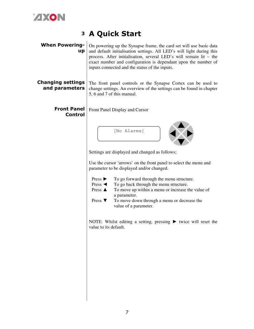
Front Panel Display and Cursor
Settings are displayed and changed as follows;
Use the cursor ‘arrows’ on the front panel to select the menu and
parameter to be displayed and/or changed.
Press ► To go forward through the menu structure.
Press ◄ To go back through the menu structure.
Press ▲ To move up within a menu or increase the value of
a parameter.
Press ▼ To move down through a menu or decrease the
value of a parameter.
NOTE: Whilst editing a setting, pressing ► twice will reset the
value to its default.
[No Alarms]
8
Example of
changing parameters using
front panel control
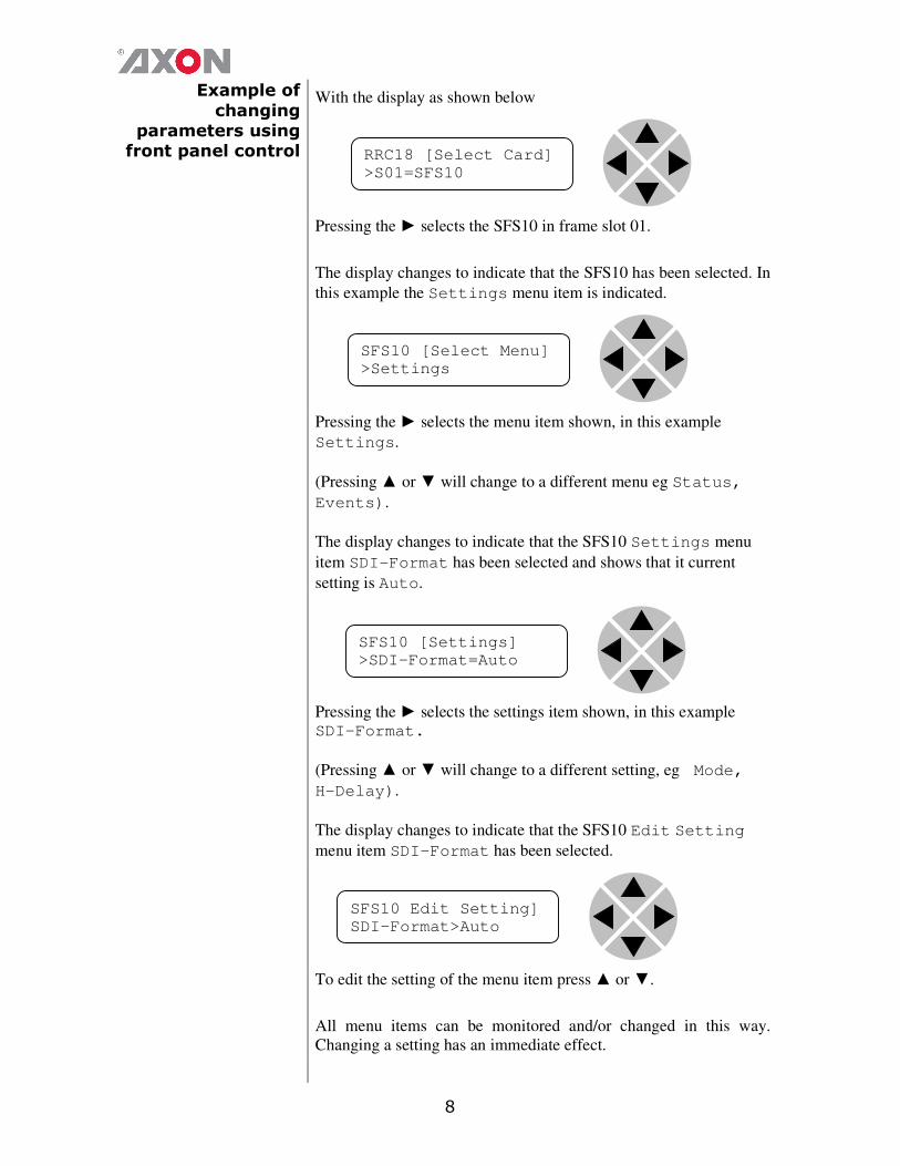
With the display as shown below
Pressing the ► selects the SFS10 in frame slot 01.
The display changes to indicate that the SFS10 has been selected. In
this example the Settings menu item is indicated.
Pressing the ► selects the menu item shown, in this example
Settings.
(Pressing ▲ or ▼ will change to a different menu eg Status,
Events).
The display changes to indicate that the SFS10 Settings menu
item SDI-Format has been selected and shows that it current
setting is Auto.
Pressing the ► selects the settings item shown, in this example SDI-Format.
(Pressing ▲ or ▼ will change to a different setting, eg Mode,
H-Delay).
The display changes to indicate that the SFS10 Edit Setting
menu item SDI-Format has been selected.
To edit the setting of the menu item press ▲ or ▼.
All menu items can be monitored and/or changed in this way.
Changing a setting has an immediate effect.
RRC18 [Select Card]
>S01=SFS10
SFS10 [Select Menu]
>Settings
SFS10 [Settings]
>SDI-Format=Auto
SFS10 Edit Setting]
SDI-Format>Auto

9
Synapse Cortex Software
Synapse Cortex can be used to change the settings of Synapse
modules from a PC, either locally or remotely. The software enables
communication based on TCP/IP between the Setup PC and
Synapse frames/modules.
Each Synapse frame is addressed through its rack controller’s
unique IP address, giving access to each module, its menus and
adjustment items. Synapse Cortex has access to data contained
within the Synapse module and displays it on a GUI. The software
has an intuitive structure following that of the module that it is
controlling.
For operation of Synapse Cortex, please refer to the Cortex manual.
Menu Structure Example
Slot Module Item Parameter Setting
▲
▲
S02 Identity
▲ ▲
S01 SFS10 ► Set-
tings
► Standard_dig ► Auto
▼ ▼ ▼ ▼
S00 RRC18 Status Mode 625
▼ ▼ ▼
Events Ref-Input 525
▼
H-Delay
▼
▼
NOTE: Further information about Front Panel Control and
Synapse Cortex can be obtained from the RRC and RRS operational
manuals and the Cortex help files.
10
4 The GFS-HFS-SFS010 Card
Introduction The GFS010, HFS010 and SFS010 are frame synchronizers with 16
channel audio transparency and color correcting capabilities.
The GFS010 is compatible with 270Mb/s, 1.5Gb/s and 3Gb/s for
full 1080p/50 or 1080p/59.94 use. The HFS010 is compatible with
SD-SDI (270Mb/s) and HD-SDI (1.5Gb/s) and can be future
upgraded to 3Gb/s compatibility. The SFS010 is limited to 270Mb/s
only but can also be upgraded to HD or even 3Gb/s.
Features
� 1 SDI input
� Compatible with the following input formats (auto selecting)
(1080p only for GFS010):
� 1080p/59.94
� 1080p/50
� 1080i/59.94
� 1080i/50
� 1080p/29.97
� 1080p25
� 1080p24
� 720p/59.94
� 720p50
� SD525
� SD625
� Color corrector
� Transparent for 16 channels of embedded audio
� Video proc-amp (Y and C control)
� Hue control for NTSC inputs
� Locks to a Bi-Level or a Tri-level sync, or to an SDI input.
� Full control and status monitoring through the front panel of the
SFR04/SFR08/SFR18 frame and the Ethernet port (ACP)
� Frame sync with output phase control in Lines and pixels with
respect to reference
NOTE: The frame synchronizer works at best if the inputs are
switched according the SMPTE guidelines described in RP168.
This ensures that not only the picture but also the ancillary data
remains correct. The frame synchronizer however can handle
complete asynchronous switching at the input.
To ensure correct operation the F-delay of the card needs to be 1 or
higher so there is enough time to mask the error.
Applications � Transmission output frame synchronizer with backup input.
� General purpose post router autophaser.
11
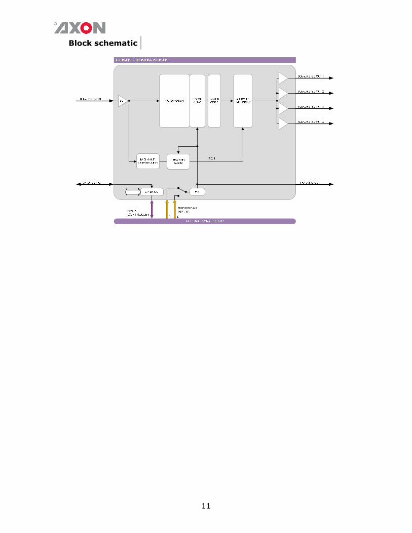
Block schematic

12
5 Settings Menu
Introduction The settings menu displays the current state of each
GFS/HFS/SFS010 setting and allows you to change or adjust it.
Settings can be changed using the front panel of the Synapse frame
(SFR18, SFR08 or SFR04) or with Cortex. Also the SCP08 control
can be used. Please refer to chapter 3 for information on the
Synapse front panel control and Cortex.
Note: All items preceded with a #-sign are part of the presets.
SYSTEM SETTINGS
IO-Ctrl This card has separate presets for the input and output settings under
the ‘SYSTEM SETTINGS’ header. With this item you select how
the IO presets are controlled: Manually (manual) or via GPI-
triggers (GPI, GPI-A, GPI-B or GPI-C). By default it is set to
Manual.
IO_Prst_Act With this item you can manually change the currently active IO
settings. Can be any preset between 1 and 8. By default it is set to 1.
All menu settings that are preceded with a ‘# ‘-prefix under the
‘SYSTEM SETTINGS’ header are part of the preset.
IO_Prst_Edit Here you can select which of the 8 selectable IO settings presets
you want to edit. Changing this will not change the active preset,
unless the currently active preset is the same you are going to edit.
All menu settings that are preceded with a ‘# ‘-prefix under the
‘SYSTEM SETTINGS’ header are part of the preset.
#Inp_SelA With this item you can select which input you want to use. Can be
SDI-1 (SDI input 1), a Zoneplate or a Colorbar as input. Can
also be set to Off to switch off the output entirely. The default for
this setting is SDI-1.
#Out-Frmt With Out-Frmt you can set what the output should be. Possible
settings are:
� 1080i60 (default), 1080i50 (HFS/GFS only)
� 1080p30, 1080p25, 1080p24 (HFS/GFS only)
� 720p60, 720p50 (HFS/GFS only)
� SD525, SD625
� 1080p50, 1080p60 (GFS only)

13
#IO-Map
(GFS only)
With this setting you can select the 3Gb/s mapping in case the input
format is 1080p50 or 1080p60. Can be manually set to Level A or
Level B. You can also choose to set it to auto, in which case the
GDL will automatically detect whether the input is Level A or
Level B.
#V-delay V-Delay setting allows adjustment of the vertical phase of the
output signal with respect to the selected reference input.
The V-Delay setting gives a delay in addition to the reference
timing. For example: if the V-Delay is set to 10 TV HD lines, the
output signal will be delayed by reference timing + 10 TV HD lines.
The signal is delayed (advanced) with respect to the phase of the
reference signal. The available range is from 0 to a maximum of
1125 lines (dependant on I/O format). The default setting is 0ln.
The preset master for this is Out-Frmt, hence the ‘#’-prefix.
#H-delay The H-Delay setting allows adjustment of the Horizontal phase of
the output signal with respect to the selected reference input.
The H-Delay setting gives a delay in addition to the reference
timing. For example: if the H-Delay is set to 10 pixels, the output
signal will be delayed by reference timing + 10 pixels. The signal is
delayed (advanced) with respect to the phase of the reference signal.
The available range is from 0 to a maximum of 5124 pixels
(dependant on I/O format). The default setting is 0px. The preset
master for this is Out-Frmt, hence the ‘#’-prefix.
#Freeze_A Freeze enables the capture of one Video Field or Frame (depending
on the setting Freeze_Mode). The settings for Freeze are On or
Off. The default is Off.
Delay-Status It is possible to display (in the status menu IODelayA and
IODelayB) the processing time of the card in the status menu.
This setting allows you to switch this function ON or OFF. Default
setting is OFF
Lock-Mode Lock-Mode determines whether the card is locked to his input
(input 1), to the reference (Ref1 or Ref2) or freerun (not
locked). By default it is set to Ref1. Can also be set to RefAuto.
When set to RefAuto the card chooses ref1 as its source.
Whenever ref1 fails, it will switch to ref 2 (only for SFR08 and
SFR18 frames and only when ref2 offers the same ref format as ref
1). When ref 1 is back up again, it will only automatically switch
back to ref 1 when ref 2 fails.
14
Ref-Type Sets the type of incoming reference. Can be either Bi-Level or
Tri-Level. Default is Bi-Level.
P60-P50_Sync With this setting you can choose to synchronize each one frame
or each two frames. Default is One Frame. The two-frame-
synchronize mode only works for 720p60, 720p50, 1080p50 and
1080p60 standards.
ANC_BlankA With this setting you can Blank the vertical ancillary data only (V-
Only), blank de horizontal ancillary data only (H-only) or blank
both vertical an horizontal ancillary data (H_And_V). You can also
choose to not blank any data (Off), which is also default.
Freeze_Mode Freez_Mode allows you to choose between storing a complete
Video Frame or Field (double written) in case of a video freeze.
The default setting is Field
PrstEditView With this setting set to Follow Active, the edit preset settings
(like for instance UP_Prst_editA and UP_Prst_editB) will
follow the active preset when the active preset is changed. This to
avoid confusion when changing the active. Set to Independent
the edit preset will not automatically follow active preset changes.
By default set to Follow Active.
PatternSpeed Sets the speed of the test-pattern (see settings Inp_SelA and
Inp_SelB) animation between 0 (still) and 15 (fast). Default is 1.
Input_loss_A Input_loss_A determines what the output of outputs A is in
case of lost input:
� Freeze: a capture of the last good field or frame.
� Colorbar: a color bar
� Zoneplate: a zone plate
� Black: a black output.
� Grey: a grey output.
� Green: a green output.
� Freeze 1 sec: a freeze of the last field or frame for 1
second. After 1 second the output framework is disabled.
� Freeze 5 sec: Same as Freeze 1 sec, only holding the
freeze frame/field for 5 seconds.
The default setting is freeze.

15
INSERTER
This card can insert several data values in the VBI of the outputs.
With the following settings you can choose what you want to insert.
Timecode_Inp With this card it is possible to copy the embedded timecode
information of either input SDI-1 or input SDI-2 to the output.
With this setting you select which input you want to use, or switch
the timecode inserting Off (default).
VITC_Ln_In With this setting you can select what line of the input you want to
copy the VITC data from (only when input is SD). Can be any line
between line 7 and line 22. Default is line 19.
VITC_Ln_Ctrl Here you can choose whether you want to select the line, to where
you want to copy the timecode data to, manually (manual) or use
the information in the ATC_DBB package to select the lines
(ATC_DBB package contains information about the line duplication
as well). Default is Manual.
VITC_Ln_625 When VITC_Ln_Ctrl is set to Manual, with this setting you can
select a line between 7 and 22 when the output is SD625. Default is
line 19.
VITC_Ln_525 When VITC_Ln_Ctrl is set to Manual, with this setting you can
select a line between 7 and 22 when the output is SD525. Default is
line 10.
VITC_Ln_Dup When set to On, the VITC line is duplicated to the above selected
line + 2 lines.
Ins_CtrlA With this item you select how the inserter presets are controlled:
Manually (manual), via GPI-triggers (GPI, GPI-A, GPI-B or
GPI-C), via changes of the SD Aspect Ratio (SD_AR) or the HD
aspect ratio (S2016) (AFD)). Default is Manual.
Ins_Prst_ActA With this item you can manually change the currently active preset
when in transparent mode. Can be any preset between 1 and 16. By
default it is set to 1. All menu settings that are preceded with a
‘#Ins’-prefix are part of the preset.
16
Ins_Prst_EditA Here you can select which of the 16 selectable presets you want to
edit when in a transparent mode. Changing this will not change the
active preset, unless the currently active preset is the same you are
going to edit. All menu settings that are preceded with a ‘#Ins’-
prefix are part of the preset.
#VI-InsertA You can turn VI insertion on or off for. Default is Off.
#VI-DataA With the #VI-InsertA setting set to on, you can select VI values
with this setting, which you want to be inserted. possible are all VI
values between 4:3_0 and 4:3_7 and the settings between
16:9_0 and 16:9_7. Default is 4:3_0.
#WSS-InsertA You can choose which type of WSS data you want to insert with
this setting, or switch WSS insertion entirely off (default value).
You can set it to Standard or Extended.
#WSS-StndA With the #WSS-InsertA setting set to Standard, you can
select WSS standard values with this setting, which you want to be
inserted. possible are all WSS values between 1_vid and 8_vid
and the settings between 1_flm and 8_flm. Default is 1_vid.
#WSS-ExtndA With the #VI-InsertA setting set to on, you can select VI values
with this setting, which you want to be inserted. possible are all
WSS values between 4:3_0 and 4:3_7 and the settings between
16:9_0 and 16:9_7. Default is 4:3_0.
#VI-DataA With the #WSS-InsertA setting set to extended, you can
select WSS extended values with this setting, which you want to be
inserted. possible are all VI settings between 4:3_0 and 4:3_7
and the settings between 16:9_0 and 16:9_7. Default is 4:3_0.
#S2016-InsertA You can turn S2016 (AFD) insertion on or off. Default is Off.
#S2016-DataA With the #S2016-InsertA setting set to on, you can select AFD
values with this setting, which you want to be inserted. possible are
all AFD values between AFD0 and AFD15.

17
#OSD-StyleA With this setting you select how the on-screen display text should
be displayed. Possible are:
� Off (no OSD)
� Transp (transparent text)
� Masked (OSD displayed in a black box)
� Blink-Transp (blinking transparent text)
� Blink-Masked (blinking text in a black box)
#OSD-TextA Here you can set a 10 character long text which should be displayed
on-screen when the above setting is not set to Off.
VIDEO PROC
GainA With this setting you control the overall gain of the video between
50 and 150%. Default is 100%.
R-GainA R-GainA controls the Red gain. The control range is between 50%
and 150%. The default setting is 100%.
G-GainA G-GainA controls the Green gain. The control range is between
50% and 150%. The default setting is 100%.
B-GainA B-GainA controls the Blue gain. The control range is between
50% and 150%. The default setting is 100%.
BlackA BlackA controls the total R-G-B Black gain. The range is between
–128bit and 127bit. The default setting is 0bit.
R-BlackA R-BlackA controls the Red-Black. The control range is between –
128bits and 127 bits in steps of 1 bit. The default setting is 0 bit.
G-BlackA G-BlackA controls the Green-Black. The control range is between
–128bits and 127 bits in steps of 1 bit. The default setting is 0 bit.
B-BlackA B-BlackA controls the Blue-Black. The control range is between –
128bits and 127 bits in steps of 1 bit. The default setting is 0 bit.
CVBS-Hue Here you can change the analog input hue between -90 and 90.

18
AUDIO PROC AMP
Audio-Phase If this setting is set to Align, the card ensures audio-phase
alignment between multiple audio channels and audio groups,
which is necessary for multi-channel (surround) purposes. If errors
in the signal-chain occur the de-embedder blocks reset
synchronously to maintain audio-phase-alignment.
If this setting is set to Off, the card eats-all audio including errors.
Even if there are DBN/ANC/ECC or channel-sequence errors, the
de-embedder will pass them. Be aware that audio-phase-alignment
between multiple audio channels and audio groups can not be
maintained if this setting is set to Off.
Note: This setting can be helpful to solve problems in the field
using equipment which doesn’t follow the standards correctly.
AudioStatusBits With this setting you select whether the audio status bits should be
Transparent (off) (same status bit on the outputs as on the inputs)
or to overwrite (on) them with new status bits.
emb_aud_hand_A Embedded audio handling for channel A. This card has a built-in
embedder, de-embedder and audio gain stage. This menu item
controls the functionality of these stages.
■ Blank: blanks the horizontal blanking.
■ Pass: passes the audio un-processed.
■ Process: controls the ‘smart’ audio handling.
‘smart’ audio handling: the selected groups in the following Grp-A-
Sel and Grp-B-Sel setting item are de-embedded. The audio is
routed through an audio gain stage and is re-embedded in the
selected group afterwards. This is performed after the frame
synchronizer. When a video (+embedded audio) frame needs to be
rewritten or removed as a result of an asynchronous SD/HD/3Gb/s
input, the audio gain stage ramps down the selected group prior to
the action and ramps up afterwards. This whole process masks
audio irregularities that are audible in a normal Frame synchronizer.
When using the Pass setting DOLBY-E is transfered with
minimum delay.
Audio_Ctrl With this setting you select how the audio presets should be
controlled. Can be either Manually (Manual), via GPI-triggers
(GPI, GPI-A, GPI-B or GPI-C), via the SD aspect ratio (SD-AR)
or via the HD aspect ratio (S2016).
Audio_Prst_act With this item you can manually change the currently active audio
preset. Can be any preset between 1 and 16. By default it is set to 1.
All menu settings that are preceded with a ‘#Emb’-prefix are part of
the preset.
19
Audio_Prst_Edit Here you can select which of the 16 selectable audio presets you
want to edit. Changing this will not change the active preset, unless
the currently active preset is the same you are going to edit. All
menu settings that are preceded with a ‘#Emb’-prefix are part of the
preset.
EMBEDDER
#Emb-AB-Mode With Emb-AB-Mode you select how the audio in groups A and B
should be embedded into the video: overwrite the exsisting
audio, or Append. Default is overwrite.
#EmbA_Grp With this setting you select in to which audio group (= 4 audio
channels) of the outputs you want to embed the first 4 forwarded
audio channels coming from the de-embedders. Can be group1,
group2, group3 or group4. You can also choose to not use
these 4 audio channels for anything by setting this item to off. By
default it is set to Group1.
#EmbA1_Inp ~
#EmbA4_Inp With these settings you can select where the corresponding audio
channels (channel A1 till channel A4) of the outputs are coming
from. In this card you can only choose to get the audio from the de-
embedder of the active input (Demb-Input), or to mute the
corresponding channel (set to off). Defaults here are Off.
#EmbB_Grp With this setting you select in to which audio group (= 4 audio
channels) of the outputs you want to embed the second 4 forwarded
audio channels coming from the de-embedders/add-on bus. Can be
group1, group2, group3 or group4. You can also choose to
not use these 4 audio channels for anything by setting this item to
off. By default it is set to Group2.
#EmbB1_Inp ~ #EmbB4_Inp
With these settings you can select where the corresponding audio
channels (channel B1 till channel B4) of the outputs are coming
from. In this card you can only choose to get the audio from the de-
embedder of the active input (Demb-Input), or to mute the
corresponding channel (set to off). Defaults here are Off.
#Emb-CD-Mode With Emb-AB-Mode you select how the audio in groups C and D
should be embedded into the video: overwrite the exsisting
audio, or Append. Default is overwrite.
20
#EmbC_Grp With this setting you select in to which audio group (= 4 audio
channels) of the outputs you want to embed the third group of 4
forwarded audio channels coming from the de-embedders/add-on
bus. Can be group1, group2, group3 or group4. You can also
choose to not use these 4 audio channels for anything by setting this
item to off. By default it is set to Group2.
#EmbC1_Inp ~
#EmbC4_Inp With these settings you can select where the corresponding audio
channels (channel C1 till channel C4) of the outputs are coming
from. In this card you can only choose to get the audio from the de-
embedder of the active input (Demb-Input), or to mute the
corresponding channel (set to off). Defaults here are Off.
#EmbD_Grp With this setting you select in to which audio group (= 4 audio
channels) of the outputs you want to embed the last 4 forwarded
audio channels coming from the de-embedders/add-on bus. Can be
group1, group2, group3 or group4. You can also choose to
not use these 4 audio channels for anything by setting this item to
off. By default it is set to Group2.
#EmbD1_Inp ~ #EmbD4_Inp
With these settings you can select where the corresponding audio
channels (channel D1 till channel D4) of the outputs are coming
from. In this card you can only choose to get the audio from the de-
embedder of the active input (Demb-Input), or to mute the
corresponding channel (set to off). Defaults here are Off.
GPI MODE
GPI-Ctrl You can set the GPI to be triggered in a latching manner or in a
nonLatching manner. Default for this is Latch.

21
GPI_1 ~ GPI_5 In this card it is possible to make the 5 available GPI triggers part of
a GPI pool that can control the various functions in the card
separately (all Xx_Ctrl items of the menu). With these item you
can select which pool the corresponding GPI is part of and in what
way it should trigger. You can also choose to not use the
corresponding GPI at all by setting it to Off. Possible settings are:
� GPI A: part of GPI-A pool, triggered once Take A is closed.
� GPI B: part of GPI-B pool, triggered once Take B is closed.
� Take A: part of GPI-A pool, used to trigger GPI A.
� Take B: part of GPI-B pool, used to trigger GPI B.
� GPI Prio A: part of GPI-A pool, working in a priority
manner (highest closed GPI of the pool is activated)
� GPI Prio B: : part of GPI-B pool, working in a priority
manner (highest closed GPI of the pool is activated)
� GPI Prio C: part of GPI-C pool, working in a priority
manner (highest closed GPI of the pool is activated)
Please refer to ‘Appendix 2: GPI’s explained’ for a more elaborate
explanation of the GPI settings.
NETWORK
IP_Conf0 With this setting you can let the card obtain an IP address
automatically via DHCP, or appoint a manual set IP address. By
default this setting is set to Manual.
mIP0 When IP_Conf0 is set to manual, you can type in the preferred
IP address here. By default it is set to 172.16.1.2
mNM0 With IP_Conf0 set to manual, with this setting you can set a
Netmask. Default is 255.255.0.0
mGW0 With IP_Conf0 set to manual, this setting let you set a Standard
Gateway. Default is set to 172.16.0.1
NetwPrefix0 Here you can set the proper network prefix if required.
22
6 Status Menu
Introduction The status menu indicates the current status of each item listed
below.
sInp1 This status item indicates the presence and format of a valid
signal in input 1. This is displayed as:
� 1080P60
� 1080p50
� 1080i60
� 1080i50
� 1080p30
� 1080p25
� 1080p24
� 720p60
� 720p50
� SD525
� SD625
� NA
sInp1_VI Displays the detected VI value found in input1. This is displayed
as follows:
� 4:3_0
� 4:3_1
� 4:3_2
� 4:3_3
� 4:3_4
� 4:3_5
� 4:3_6
� 4:3_7
� 16:9_0
� 16:9_1
� 16:9_2
� 16:9_3
� 16:9_4
� 16:9_5
� 16:9_6
� 16:9_7
� NA (no VI detected)
23
sInp1_WSS-Stnd This status item displays the detected standard WSS value of
input 1. this is displayed as follows:
� 1_vid
� 2_vid
� 3_vid
� 4_vid
� 5_vid
� 6_vid
� 7_vid
� 8_vid
� 1_flm
� 2_flm
� 3_flm
� 4_flm
� 5_flm
� 6_flm
� 7_flm
� 8_flm
� NA (no standard WSS detected)
sInp1_WSS-Extd This item displays the detected extended WSS value of input 1.
This is displayed as follows:
� 4:3_0
� 4:3_1
� 4:3_2
� 4:3_3
� 4:3_4
� 4:3_5
� 4:3_6
� 4:3_7
� 16:9_0
� 16:9_1
� 16:9_2
� 16:9_3
� 16:9_4
� 16:9_5
� 16:9_6
� 16:9_7
� NA (no WSS extended detected)
24
sInp1_S2016 This item displays the detected SMPTE 2016 (AFD) values of
input 1. This is displayed as follows:
� AFD0
� AFD1
� AFD2
� AFD3
� AFD4
� AFD5
� AFD6
� AFD7
� AFD8
� AFD9
� AFD10
� AFD11
� AFD12
� AFD13
� AFD14
� AFD15
� NA (no S2016 detected)
sInp1-Map
(GFS only)
This indicates the mapping of input 1 when the input format is
3Gb/s (1080p50 or 1080p60). Can be Level A or Level B.
When the input format is not 1080p60 or 1080p50, this item
indicates NA.
IODelayA Displays the total delay in ms of the outputs. can be a value
between 0ms and 15000ms.
SwitchLnA Displays what line is detected the switchline. Can be any line
between 0 and 1125.
SwitchLn_LenA Displays the length of the detected switchline in pixels.
SwitchLn_PosA Displays the position on the detected switchline where the switch
occurred (in pixels). Only works on blanked switchlines.
FunctionA Displays the current function of the outputs. For this card it can
only be Trans, TestPattern or NA.
Ref Displays whether a correct reference is found (Present) or not
(NA)
25
GPI Displays the currently closed GPI contacts. This is displayed as
for instance 1_3_ when contacts 1 and 3 are closed and for
instance _234 when contacts 2, 3 and 4 are closed.
GPIA Displays the current value of GPI pool A
GPIB Displays the current value of GPI pool B
GPIC Displays the current value of GPI pool C
OutputA-Map
(GFS only)
This indicates the mapping of the (last known) output when the
output format is 3Gb/s (1080p50 or 1080p60). Can be Level A
or Level B. When the output format is not 1080p60 or
1080p50, this item indicates NA.
NET STATUS
IP_Addr0 This item displays the status of the IP address. It can be manual,
DHCP asking, DHCP Leased or DHCP Infin.
MAC0 This item displays the MAC address of the card.
IP0 This item displays the current IP address of the card.
NM0 This item displays the current Netmask of the card.
GW0 This item displays the current Standard Gateway of the card.
26
7 Events Menu
Introduction An event is a special message that is generated on the card
asynchronously. This means that it is not the response to a request to
the card, but a spontaneous message.
What is the Goal of
an event? The goal of events is to inform the environment about a changing
condition on the card. A message may be broadcast to mark the change
in status. The message is volatile and cannot be retrieved from the
system after it has been broadcast. There are several means by which
the message can be filtered.
Events The events reported by the GFS/HFS/SFS010 are as follows;
Announcements Announcements is not an event. This item is only used for
switching the announcement of status changes on/off. 0=off, other =on
Input_A Input_A can be selected between 0 .. 255. 0= no event, 1..255 is the
priority setting.
Input_B Input_B can be selected between 0 .. 255. 0= no event, 1..255 is the
priority setting.
Ref-Status Reference can be selected between 0 .. 255. 0= no event, 1..255 is the
priority setting.
What information is
available in an event?
The message consists of the following items;
1) A message string to show what has happened in text, for example:
“INP_LOSS”, “REF_LOSS”, “INP_RETURN”.
2) A tag that also shows what happens, but with a predefined number:
e.g. 1 (= loss of input), 2 (= loss of reference), 129(= 1+128 =
return of input). For a list of these predefined tags see the table on
the next page.
3) A priority that marks the importance of an event. This value is
defined by the user and can have any value between 1 and 255, or
0 when disabled.
4) A slot number of the source of this event.
27
The Message String The message string is defined in the card and is therefore fixed. It may
be used in controlling software like Synapse Set-up to show the event.
The Tag The tag is also defined in the card. The tag has a fixed meaning. When
controlling or monitoring software should make decisions based on
events, it is easier to use the tag instead of interpreting a string. The
first implementation is the tag controlled switch in the GPI16.
In cases where the event marks a change to fault status (e.g. 1 for Loss
of Input) the complement is marked by the tag increased by 128 (80hex)
(e.g. 129 (81hex) for Return of Input).
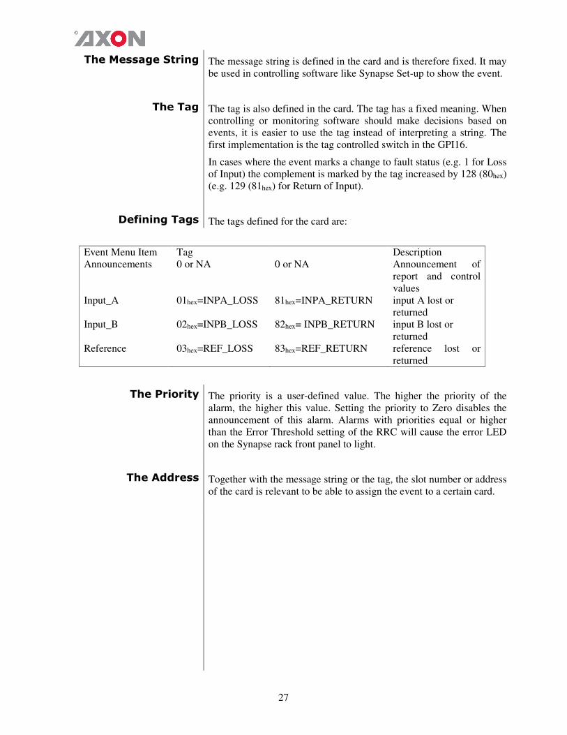
Defining Tags The tags defined for the card are:
Event Menu Item Tag Description
Announcements 0 or NA 0 or NA Announcement of
report and control
values
Input_A 01hex=INPA_LOSS 81hex=INPA_RETURN input A lost or
returned
Input_B 02hex=INPB_LOSS 82hex= INPB_RETURN input B lost or
returned
Reference 03hex=REF_LOSS 83hex=REF_RETURN reference lost or
returned
The Priority The priority is a user-defined value. The higher the priority of the
alarm, the higher this value. Setting the priority to Zero disables the
announcement of this alarm. Alarms with priorities equal or higher
than the Error Threshold setting of the RRC will cause the error LED
on the Synapse rack front panel to light.
The Address Together with the message string or the tag, the slot number or address
of the card is relevant to be able to assign the event to a certain card.
28
8 LED Indication Error LED The error LED indicates an error if the internal logic of the
GFS/HFS/SFS010 card is not configured correctly or has a
hardware failure.
Input_A LED This LED indicated the presence of a valid SDI video signal on
input A.
Input_B LED This LED indicated the presence of a valid SDI video signal on
input B.
ANC Data LED Indicates the presence of embedded audio within the input signal.
Reference LED Indicated the presence of a valid reference signal on the selected
reference input connector (ref-1 or ref-2).
Data Error LED This LED indicates a CRC error.
Connection LED This LED illuminates after the card has initialized. The LED
lights for 0.5 seconds every time a connection is made to the card.
Error LED The error LED indicates an error if the internal logic of the card is
not configured correctly or has a hardware failure.

29
9 Block Schematic
30
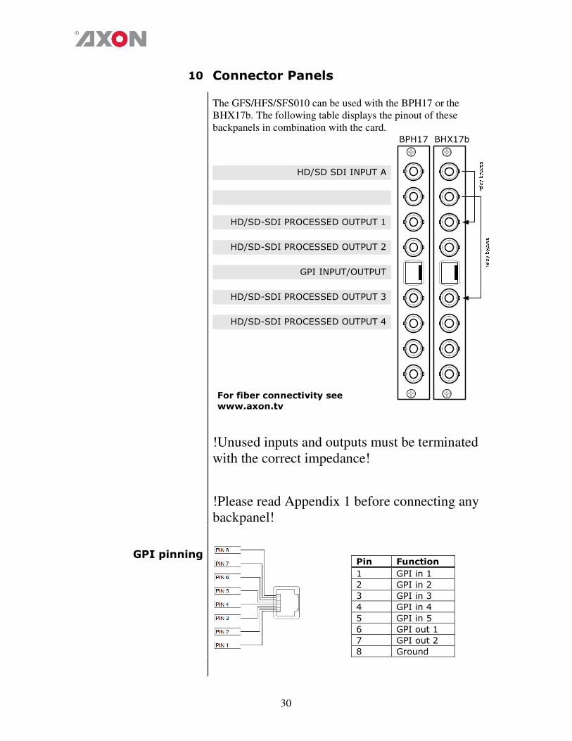
10 Connector Panels
The GFS/HFS/SFS010 can be used with the BPH17 or the
BHX17b. The following table displays the pinout of these
backpanels in combination with the card.
BPH17 BHX17b
HD/SD SDI INPUT A
HD/SD-SDI PROCESSED OUTPUT 1
HD/SD-SDI PROCESSED OUTPUT 2
GPI INPUT/OUTPUT
HD/SD-SDI PROCESSED OUTPUT 3
HD/SD-SDI PROCESSED OUTPUT 4
For fiber connectivity see
www.axon.tv
!Unused inputs and outputs must be terminated
with the correct impedance!
!Please read Appendix 1 before connecting any
backpanel!
GPI pinning
Pin Function
1 GPI in 1
2 GPI in 2
3 GPI in 3
4 GPI in 4
5 GPI in 5
6 GPI out 1
7 GPI out 2
8 Ground
31
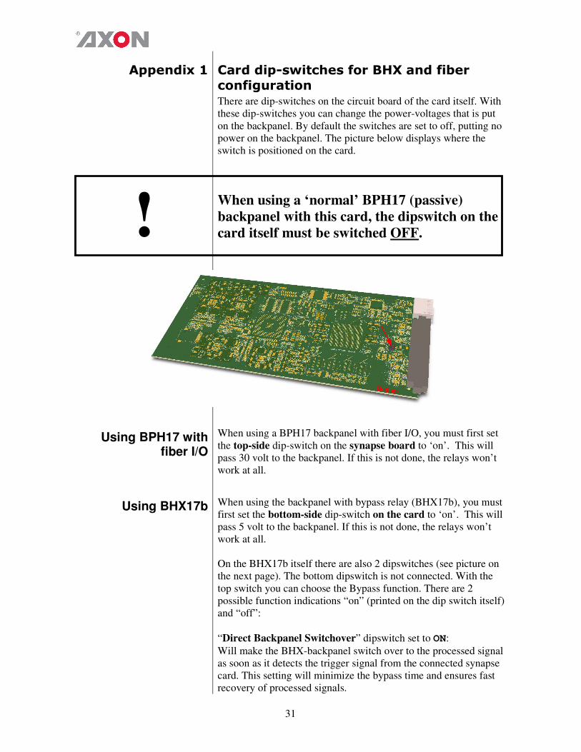
Appendix 1 Card dip-switches for BHX and fiber
configuration
There are dip-switches on the circuit board of the card itself. With
these dip-switches you can change the power-voltages that is put
on the backpanel. By default the switches are set to off, putting no
power on the backpanel. The picture below displays where the
switch is positioned on the card.
! When using a ‘normal’ BPH17 (passive)
backpanel with this card, the dipswitch on the
card itself must be switched OFF.
Using BPH17 with fiber I/O
When using a BPH17 backpanel with fiber I/O, you must first set
the top-side dip-switch on the synapse board to ‘on’. This will
pass 30 volt to the backpanel. If this is not done, the relays won’t
work at all.
Using BHX17b When using the backpanel with bypass relay (BHX17b), you must
first set the bottom-side dip-switch on the card to ‘on’. This will
pass 5 volt to the backpanel. If this is not done, the relays won’t
work at all.
On the BHX17b itself there are also 2 dipswitches (see picture on
the next page). The bottom dipswitch is not connected. With the
top switch you can choose the Bypass function. There are 2
possible function indications “on” (printed on the dip switch itself)
and “off”:
“Direct Backpanel Switchover” dipswitch set to ON:
Will make the BHX-backpanel switch over to the processed signal
as soon as it detects the trigger signal from the connected synapse
card. This setting will minimize the bypass time and ensures fast
recovery of processed signals.

32
The ON setting is recommended if the BHX-backpanel is used in
combination with synapse cards:
� which have a short initialization time, or
� which have a delayed trigger-signal onboard.
“Direct Backpanel Switchover” dipswitch set to OFF (default):
Will make the BHX-backpanel switch after about 15 seconds from
the moment the BHX-backpanel detects the trigger signal from the
connected synapse card. This setting will allow more time for
complex synapse cards to finish initialization and stabilize proper
signal processing before the backpanel switches over to the
processed signal.
The OFF setting is recommended if the BHX-backpanel is used in
combination with synapse cards:
� which are more complex and thus need longer initialization
time and do NOT have a delayed trigger-signal onboard.
Note: In case of power failure or when the synapse board is
extracted from the frame the bypass is immediately active.
33
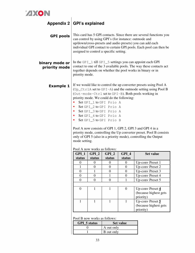
Appendix 2 GPI’s explained
GPI pools This card has 5 GPI contacts. Since there are several functions you
can control by using GPI’s (for instance: outmode and
up/down/cross-presets and audio presets) you can add each
individual GPI contact to certain GPI pools. Each pool can then be
assigned to control a specific setting.
binary mode or
priority mode
In the GPI_1 till GPI_5 settings you can appoint each GPI
contact to one of the 3 available pools. The way these contacts act
together depends on whether the pool works in binary or in
priority mode.
Example 1 If we would like to control the up converter presets using Pool A
(Up_CtrlA set to GPI-A) and the outmode setting using Pool B
(Out-mode-Ctrl set to GPI-B). Both pools working in
priority mode. We could do the following:
� Set GPI_1 to GPI Prio A
� Set GPI_2 to GPI Prio A
� Set GPI_3 to GPI Prio A
� Set GPI_4 to GPI Prio A
� Set GPI_5 to GPI Prio B
Pool A now consists of GPI 1, GPI 2, GPI 3 and GPI 4 in a
priority mode, controlling the Up converter preset. Pool B consists
only of GPI 5 (also in a priority mode), controlling the Output
mode setting.
Pool A now works as follows:
GPI_1
status
GPI_2
status
GPI_2
status
GPI_4
status
Set value
0 0 0 0 Up-conv Preset 1
1 0 0 0 Up-conv Preset 2
0 1 0 0 Up-conv Preset 3
0 0 1 0 Up-conv Preset 4
0 0 0 1 Up-conv Preset 5
0 1 1 0 Up-conv Preset 4
(because highest gets
priority)
1 1 1 1 Up-conv Preset 5
(because highest gets
priority)
Pool B now works as follows:
GPI_5 status Set value
0 A out only
1 B out only
34
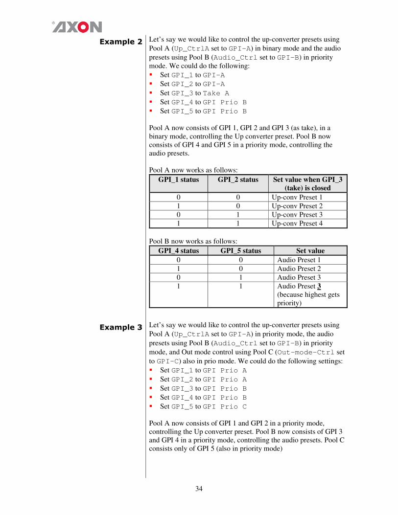
Example 2 Let’s say we would like to control the up-converter presets using
Pool A (Up_CtrlA set to GPI-A) in binary mode and the audio
presets using Pool B (Audio_Ctrl set to GPI-B) in priority
mode. We could do the following:
� Set GPI_1 to GPI-A
� Set GPI_2 to GPI-A
� Set GPI_3 to Take A
� Set GPI_4 to GPI Prio B
� Set GPI_5 to GPI Prio B
Pool A now consists of GPI 1, GPI 2 and GPI 3 (as take), in a
binary mode, controlling the Up converter preset. Pool B now
consists of GPI 4 and GPI 5 in a priority mode, controlling the
audio presets.
Pool A now works as follows:
GPI_1 status GPI_2 status Set value when GPI_3
(take) is closed
0 0 Up-conv Preset 1
1 0 Up-conv Preset 2
0 1 Up-conv Preset 3
1 1 Up-conv Preset 4
Pool B now works as follows:
GPI_4 status GPI_5 status Set value
0 0 Audio Preset 1
1 0 Audio Preset 2
0 1 Audio Preset 3
1 1 Audio Preset 3
(because highest gets
priority)
Example 3 Let’s say we would like to control the up-converter presets using
Pool A (Up_CtrlA set to GPI-A) in priority mode, the audio
presets using Pool B (Audio_Ctrl set to GPI-B) in priority
mode, and Out mode control using Pool C (Out-mode-Ctrl set
to GPI-C) also in prio mode. We could do the following settings:
� Set GPI_1 to GPI Prio A
� Set GPI_2 to GPI Prio A
� Set GPI_3 to GPI Prio B
� Set GPI_4 to GPI Prio B
� Set GPI_5 to GPI Prio C
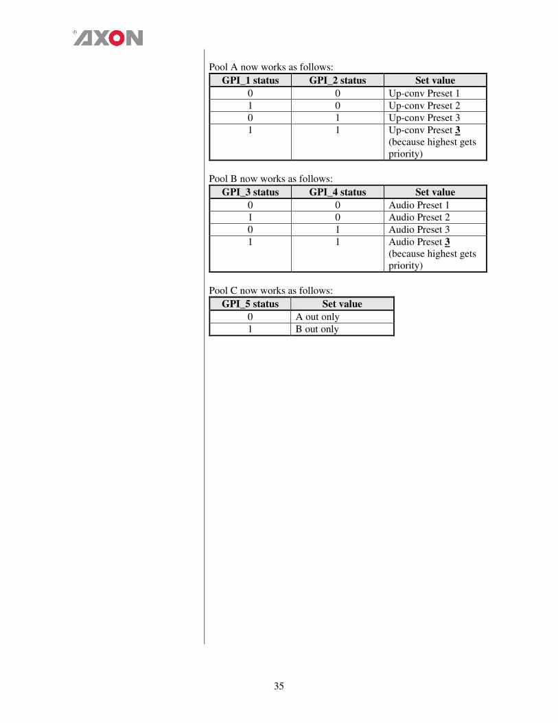
Pool A now consists of GPI 1 and GPI 2 in a priority mode,
controlling the Up converter preset. Pool B now consists of GPI 3
and GPI 4 in a priority mode, controlling the audio presets. Pool C
consists only of GPI 5 (also in priority mode)
35
Pool A now works as follows:
GPI_1 status GPI_2 status Set value
0 0 Up-conv Preset 1
1 0 Up-conv Preset 2
0 1 Up-conv Preset 3
1 1 Up-conv Preset 3
(because highest gets
priority)
Pool B now works as follows:
GPI_3 status GPI_4 status Set value
0 0 Audio Preset 1
1 0 Audio Preset 2
0 1 Audio Preset 3
1 1 Audio Preset 3
(because highest gets
priority)
Pool C now works as follows:
GPI_5 status Set value
0 A out only
1 B out only
36
This product contains open-source software This product contains open-source software licensed under the GNU Public License (GPL). A copy of the GNU Public License is included below. Under this license you are eligible to receive a copy of the source code of this software including any changes. Axon Digital Design shall provide the source code on request either through physical distribution or electronic communication. For physical distribution you may be charged a fee that covers distribution costs. This offer is valid up to three years after date of purchase. Please direct your request to the support department of Axon Digital Design. Axon Digital Design supports open-source software by participating in the development of open-source projects or submitting improvements to these projects. For more information see http://opensource.axon.tv/
GNU Public License version 2
TERMS AND CONDITIONS FOR COPYING, DISTRIBUTION AND MODIFICATION 0. This License applies to any program or other work which contains a notice placed by the copyright holder saying it may be distributed under the terms of this General Public License. The “Program”, below, refers to any such program or work, and a “work based on the Program” means either the Program or any derivative work under copyright law: that is to say, a work containing the Program or a portion of it, either verbatim or with modifi cations and/or translated into another language. (Hereinafter, translation is included without limitation in the term “modifi cation”.) Each licensee is addressed as “you”. Activities other than copying, distribution and modifi cation are not covered by this License; they are outside its scope. The act of running the Program is not restricted, and the output from the Program is covered only if its contents constitute a work based on the Program (independent of having been made by running the Program). Whether that is true depends on what the Program does. 1. You may copy and distribute verbatim copies of the Program’s source code as you receive it, in any medium, provided that you conspicuously and appropriately publish on each copy an appropriate copyright notice and disclaimer of warranty; keep intact all the notices that refer to this License and to the absence of any warranty; and give any other recipients of the Program a copy of this License along with the Program. You may charge a fee for the physical act of transferring a copy, and you may at your option offer warranty protection in exchange for a fee. 2. You may modify your copy or copies of the Program or any portion of it, thus forming a work based on the Program, and copy and distribute such modifications or work under the terms of Section 1 above, provided that you also meet all of these conditions:
a) You must cause the modified files to carry prominent notices stating that you changed the fi les and the date of any change. b) You must cause any work that you distribute or publish, that in whole or in part contains or is derived from the Program or any
part thereof, to be licensed as a whole at no charge to all third parties under the terms of this License. c) If the modified program normally reads commands interactively when run, you must cause it, when started running for such
interactive use in the most ordinary way, to print or display an announcement including an appropriate copyright notice and a notice that there is no warranty (or else, saying that you provide a warranty) and that users may redistribute the program under these conditions, and telling the user how to view a copy of this License. (Exception: if the Program itself is interactive but does not normally print such an announcement, your work based on the Program is not required to print an announcement.)
These requirements apply to the modified work as a whole. If identifiable sections of that work are not derived from the Program, and can be reasonably considered independent and separate works in themselves, then this License, and its terms, do not apply to those sections when you distribute them as separate works. But when you distribute the same sections as part of a whole which is a work based on the Program, the distribution of the whole must be on the terms of this License, whose permissions for other licensees extend to the entire whole, and thus to each and every part regardless of who wrote it. Thus, it is not the intent of this section to claim rights or contest your rights to work written entirely by you; rather, the intent is to exercise the right to control the distribution of derivative or collective works based on the Program. In addition, mere aggregation of another work not based on the Program with the Program (or with a work based on the Program) on a volume of a storage or distribution medium does not bring the other work under the scope of this License. 3. You may copy and distribute the Program (or a work based on it, under Section 2) in object code or executable form under the terms of Sections 1 and 2 above provided that you also do one of the following:
a) Accompany it with the complete corresponding machine-readable source code, which must be distributed under the terms of Sections 1 and 2 above on a medium customarily used for software interchange; or,
b) Accompany it with a written offer, valid for at least three years, to give any third party, for a charge no more than your cost of physically performing source distribution, a complete machine-readable copy of the corresponding source code, to be distributed under the terms of Sections 1 and 2 above on a medium customarily used for software interchange; or,
37
c) Accompany it with the information you received as to the offer to distribute corresponding source code. (This alternative is allowed only for noncommercial distribution and only if you received the program in objects code or executable form with such an offer, in accord with Subsection b above.)
The source code for a work means the preferred form of the work for making modifi cations to it. For an executable work, complete source code means all the source code for all modules it contains, plus any associated interface defi nition fi les, plus the scripts used to control compilation and installation of the executable. However, as a special exception, the source code distributed need not include anything that is normally distributed (in either source or binary form) with the major components (compiler, kernel, and so on) of the operating system on which the executable runs, unless that component itself accompanies the executable. If distribution of executable or object code is made by offering access to copy from a designated place, then offering equivalent access to copy the source code from the same place counts as distribution of the source code, even though third parties are not compelled to copy the source along with the object code. 4. You may not copy, modify, sublicense, or distribute the Program except as expressly provided under this License. Any attempt otherwise to copy, modify, sublicense or distribute the Program is void, and will automatically terminate your rights under this License. However, parties who have received copies, or rights, from you under this License will not have their licenses terminated so long as such parties remain in full compliance. 5. You are not required to accept this License, since you have not signed it. However, nothing else grants you permission to modify or distribute the Program or its derivative works. These actions are prohibited by law if you do not accept this License. Therefore, by modifying or distributing the Program (or any work based on the Program), you indicate your acceptance of this License to do so, and all its terms and conditions for copying, distributing or modifying the Program or works based on it. 6. Each time you redistribute the Program (or any work based on the Program), the recipient automatically receives a license from the original licensor to copy, distribute or modify the Program subject to these terms and conditions. You may not impose any further restrictions on the recipients’ exercise of the rights granted herein. You are not responsible for enforcing compliance by third parties to this License. 7. If, as a consequence of a court judgment or allegation of patent infringement or for any other reason (not limited to patent issues), conditions are imposed on you (whether by court order, agreement or otherwise) that contradict the conditions of this License, they do not excuse you from the conditions of this License. If you cannot distribute so as to satisfy simultaneously your obligations under this License and any other pertinent obligations, then as a consequence you may not distribute the Program at all. For example, if a patent license would not permit royalty-free redistribution of the Program by all those who receive copies directly or indirectly through you, then the only way you could satisfy both it and this License would be to refrain entirely from distribution of the Program. If any portion of this section is held invalid or unenforceable under any particular circumstance, the balance of the section is intended to apply and the section as a whole is intended to apply in other circumstances. It is not the purpose of this section to induce you to infringe any patents or other property right claims or to contest validity of any such claims; this section has the sole purpose of protecting the integrity of the free software distribution system, which is implemented by public license practices. Many people have made generous contributions to the wide range of software distributed through that system in reliance on consistent application of that system; it is up to the author/donor to decide if he or she is willing to distribute software through any other system and a licensee cannot impose that choice. This section is intended to make thoroughly clear what is believed to be a consequence of the rest of this License. 8. If the distribution and/or use of the Program is restricted in certain countries either by patents or by copyrighted interfaces, the original copyright holder who places the Program under this License may add an explicit geographical distribution limitation excluding those countries, so that distribution is permitted only in or among countries not thus excluded. In such case, this License incorporates the limitation as if written in the body of this License. 9. The Free Software Foundation may publish revised and/or new versions of the General Public License from time to time. Such new versions will be similar in spirit to the present version, but may differ in detail to address new problems or concerns. Each version is given a distinguishing version number. If the Program specifies a version number of this License which applies to it and “any later version”, you have the option of following the terms and conditions either of that version or of any later version published by the Free Software Foundation. If the Program does not specify a version number of this License, you may choose any version ever published by the Free Software Foundation. 10. If you wish to incorporate parts of the Program into other free programs whose distribution conditions are different, write to the author to ask for permission. For software which is copyrighted by the Free Software Foundation, write to the Free Software Foundation; we sometimes make exceptions for this. Our decision will be guided by the two goals of preserving the free status of all derivatives of our free software and of promoting the sharing and reuse of software generally.

38
NO WARRANTY 11. BECAUSE THE PROGRAM IS LICENSED FREE OF CHARGE, THERE IS NO WARRANTY FOR THE PROGRAM, TO THE EXTENT PERMITTED BY APPLICABLE LAW. EXCEPT WHEN OTHERWISE STATED IN WRITING THE COPYRIGHT HOLDERS AND/OR OTHER PARTIES PROVIDE THE PROGRAM “AS IS” WITHOUT WARRANTY OF ANY KIND, EITHER EXPRESSED OR IMPLIED, INCLUDING, BUT NOT LIMITED TO, THE IMPLIED WARRANTIES OF MERCHANTABILITY AND FITNESS FOR A PARTICULAR PURPOSE. THE ENTIRE RISK AS TO THE QUALITY AND PERFORMANCE OF THE PROGRAM IS WITH YOU. SHOULD THE PROGRAM PROVE DEFECTIVE, YOU ASSUME THE COST OF ALL NECESSARY SERVICING, REPAIR OR CORRECTION. 12. IN NO EVENT UNLESS REQUIRED BY APPLICABLE LAW OR AGREED TO IN WRITING WILL ANY COPYRIGHT HOLDER, OR ANY OTHER PARTY WHO MAY MODIFY AND/OR REDISTRIBUTE THE PROGRAM AS PERMITTED ABOVE, BE LIABLE TO YOU FOR DAMAGES, INCLUDING ANY GENERAL, SPECIAL, INCIDENTAL OR CONSEQUENTIAL DAMAGES ARISING OUT OF THE USE OR INABILITY TO USE THE PROGRAM (INCLUDING BUT NOT LIMITED TO LOSS OF DATA OR DATA BEING RENDERED INACCURATE OR LOSSES SUSTAINED BY YOU OR THIRD PARTIES OR A FAILURE OF THE PROGRAM TO OPERATE WITH ANY OTHER PROGRAMS), EVEN IF SUCH HOLDER OR OTHER PARTY HAS BEEN ADVISED OF THE POSSIBILITY OF SUCH DAMAGES.