Genesis Engineering and Design Manual - Water Heaters · Genesis Engineering and Design Manual 1...
62
Transcript of Genesis Engineering and Design Manual - Water Heaters · Genesis Engineering and Design Manual 1...


Genesis Engineering and Design Manual
1
IntroductionEngineering and Design Manual
Dear A. O. Smith Customer,
This Engineering and Design Manual has been written to aid in designing and specifying
A. O. Smith Genesis hydronic heating boilers. This manual is intended to quickly and easily
answer the most frequently asked questions regarding the Genesis product line.
This manual is intended for use by professional designers and engineers and is not meant
to be all inclusive. Reference should be made to the instruction manual accompanying the
product. This Engineering and Design Manual contains supplemental information to the
Genesis Instruction and User’s Information Manual. A copy of the complete instruction manual
can be obtained from the A. O. Smith website (www.hotwater.com), from the A. O. Smith
Customer Care Center at 1-800-527-1953, or from your local A. O. Smith Representative.
A. O. Smith is proud of our quality products, and we appreciate your interest in our
products. We hope to be working with you soon.
Sincerely yours,
A. O. Smith Water Heaters

2
Table of ContentsCHAPTER 1 - BASICS OF INSTALLATION .............................................................................5-6
Code Compliance............................................................................................................5Location...........................................................................................................................5Installation Clearances....................................................................................................5
CHAPTER 2 - SPECIAL SITUATIONS......................................................................................7-8Installation on Combustible Flooring...............................................................................7Outdoor Units ..................................................................................................................7
CHAPTER 3 - COMBUSTION AIR..........................................................................................9-12Sizing Combustion Air Louvers.......................................................................................9Combustion Air and the Genesis Boiler..........................................................................9Air for Combustion (Through the Wall)..........................................................................10Air for Combustion (Vertical Ducts)...............................................................................10Air for Combustion (Horizontal Ducts) ..........................................................................11Alternate Air for Combustion.........................................................................................11
CHAPTER 4 - SPECIAL PROBLEMS - COMBUSTION AIR ...............................................13-14Boiler Room Exhaust Fans ...........................................................................................13Contaminated Combustion Air ......................................................................................13Flammable Items...........................................................................................................14
CHAPTER 5 - VENTING SECTION.......................................................................................15-36General Venting Information..........................................................................................15Genesis Venting Categories and Venting Materials ......................................................15Genesis Boiler Category I Venting ................................................................................16Natural Draft Vertical Venting Using Boiler Room Air for Combustion (Category I)......17Masonry Chimneys - Atmospheric Draft .......................................................................18Category I Common Venting Multiple Units ..................................................................18Common Venting Genesis Boilers When Using A Stack-Rack.....................................19Category I Natural Draft Vertical Vent Termination........................................................20Category I Vertical Direct Venting (Two Pipe System Using Outdoor Air) ....................21Meeting Special State and Local Codes Requiring Direct Vent Sealed Combustion ...23Category III One Pipe Sidewall Venting Using Boiler Room Air ...................................24Category III Horizontal Two Pipe Direct Vent Using Outdoor Air ..................................25Category III Extended Horizontal Sidewall And Direct Venting (Power Assist) ............27Locating Exhaust and Combustion Air Terminations ....................................................29Special Vent Terminal Location Considerations ............................................................29Category III - Genesis Venting ......................................................................................29Termination Considerations...........................................................................................30Type “B” Double Wall Vent Sizing Tables .................................................................31-35

Genesis Engineering and Design Manual
3
Table of ContentsCHAPTER 6 - GAS SUPPLY......................................................................................................37
General Genesis Gas Supply Considerations .........................................................37-40Single Boiler Gas Pipe Sizing .......................................................................................38Gas System Sizing........................................................................................................38Multiple Appliance Gas System Sizing - Natural Gas...................................................38Multiple Appliance Gas System Sizing - Propane Gas.................................................39High Altitude Installations..............................................................................................39General Altitude Information .........................................................................................39High Altitude Sizing Considerations..............................................................................40Genesis Pre-Jet Orifices ...............................................................................................40
CHAPTER 7 - GENESIS ELECTRICAL REQUIREMENTS.......................................................41
CHAPTER 8 - HYDRONIC HEATING SYSTEMS & COMPONENTS...................................43-45Genesis Boilers .............................................................................................................43Boiler & System Water Flow Requirements..................................................................43Boiler Temperature Settings..........................................................................................44Hydronic Heating System Components ........................................................................44
CHAPTER 9 - HYDRONIC HEATING SYSTEM PIPING ......................................................47-57Primary/Secondary Piping ............................................................................................47Primary/Secondary Piping Multiple Boilers...................................................................48Boiler Operating Temperature Controls.........................................................................48Minimum System/Boiler Temperature ...........................................................................49Locating the System Temperature Sensor....................................................................49Primary/Secondary - Multiple Boiler Piping Configurations.....................................50-52For Design Temperatures of 180°F or Less ..................................................................50For Design Temperatures Over 180°F ..........................................................................51For Design Temperatures Below 120°F ........................................................................52Understanding Cast Iron and Steel Boiler Systems with Three-Way Mixing Valves.....53Efficiency of Low Mass vs. High Mass Boilers..............................................................53Retrofitting A Cast Iron Boiler With Three-Way Mixing Valve To A Copper Boiler System................................................................................................................54Special Cases - Piping Low or Varied Flow Systems ...................................................56
INDEX OF FIGURES ..................................................................................................................58
INDEX OF TABLES.....................................................................................................................59
4
Basics of Installation
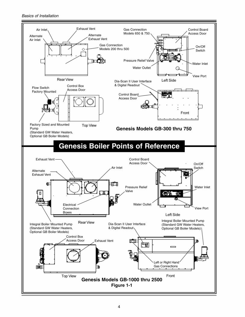
Genesis Boiler Points of Reference
Air Inlet
Air Inlet
Exhaust Vent
Exhaust Vent
Exhaust Vent
Water Outlet
Water Outlet
Water Inlet
Water Inlet
On/OffSwitch
On/OffSwitch
View Port
View Port
Pressure Relief Valve
Pressure ReliefValve
AlternateExhaust Vent
AlternateExhaust Vent
ElectricalConnectionBoxes
Gas ConnectionModels 200 thru 500
Left or Right HandGas Connections
Flow Switch Factory Mounted
Factory Sized and MountedPump(Standard GW Water Heaters,Optional GB Boiler Models)
Integral Boiler Mounted Pump(Standard GW Water Heaters,Optional GB Boiler Models)
Integral Boiler Mounted Pump(Standard GW Water Heaters,Optional GB Boiler Models)
AlternateAir Inlet
Control Box Access Door
Control Box Access Door
Control Board Access Door
Control Board Access Door
Control Board Access Door
Gas ConnectionModels 650 & 750
Dia-Scan II User Interface& Digital Readout
Dia-Scan II User Interface& Digital Readout
Genesis Models GB-300 thru 750
Genesis Models GB-1000 thru 2500Figure 1-1

Genesis Engineering and Design Manual
5
Code Compliance
The Genesis boiler design complies with the
latest edition of the American National Standards
Institute for gas-fired, low-pressure steam and hot
water boilers, ANSI Z21.13 and CSA 4.9.
In addition to the information in the instruction
manual, the boiler(s) shall be installed in strict
accordance with those installation regulations in
force in the local area where the installation is to
be made. Authorities having jurisdiction should be
consulted before installations begin. In the
absence of local codes, the installation must
comply with the latest editions of:
In the United States:
The National Fuel Gas Code, ANSI
Z223.1/NFPA 54 and the National
Electric Code, NFPA 70.
In Canada:
The installation Code CAN/CSA B149.1-00
and the Canadian
Electric Code, CSA C22.1.
Location
Before installing any boiler, careful
consideration must be given to proper location.
The location selected should be as close to the
stack or chimney as practical, offer adequate
make-up air supply, and be as centralized within
the piping system as possible. This location
should also be such that the gas ignition system
components are protected from external dripping
and spraying of water during appliance operation
and service.
Additional boiler location considerations:
• The boiler must not be installed on carpeting
(See Chapter 2).
• The boiler should not be located in an area
where it will be subject to freezing.
• The boiler should be located near a floor drain.
• The boiler should be located in an area where
leakage from the boiler or connections will not
result in damage to the adjacent area or to
lower floors of the structure.
Note: When such locations cannot be avoided,
a suitable drain pan should be installed under
the boiler. Drain pans should be fabricated with
sides at least 2 1⁄2 inches deep, with length and
width at least 2 inches greater than the
dimensions of the boiler. The drain pan must be
piped to an adequate drain and must not restrict
combustion air flow.
Installation Clearances
Sufficient area should be provided at the front
and sides of the unit for proper servicing. For ease
of service, minimum clearances of 24 inches in
the front and 18 inches on the water connection
side are recommended.
CHAPTER 1. BASICS OF INSTALLATION

6
Basics of Installation
Please note that the minimum clearances
shown are the certified minimum clearances.
Whenever possible, additional space is
recommended. Genesis boilers are approved for
installation on noncombustible flooring in an
alcove with minimum clearance to combustibles.
For installation on combustible flooring, see
Chapter 2 Special Situations.
Figure 1-2 Figure 1-3
(Table A) Minimum Clearances to Combustibles
ClearancesLocation
Figure 2 & 3Models GB/GW-400 - 750
Models GB/GW-1000 -2500
Left Side A3" 12"
(18" for Service) (18" for Service)
Rear B 3" 3"
Right Side C 3" 3"
Top D 3" 6"
FrontAlcove Alcove
(24" for Service) (24" for Service)
Vent 6" 6"
Hot Water Pipes 2" 2"
Genesis Engineering and Design Manual
7
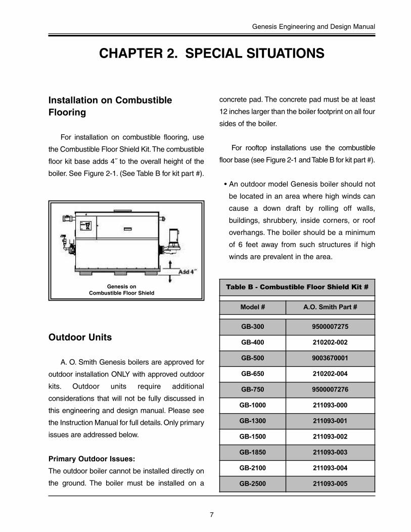
Installation on CombustibleFlooring
For installation on combustible flooring, use
the Combustible Floor Shield Kit.The combustible
floor kit base adds 4˝ to the overall height of the
boiler. See Figure 2-1. (See Table B for kit part #).
Outdoor Units
A. O. Smith Genesis boilers are approved for
outdoor installation ONLY with approved outdoor
kits. Outdoor units require additional
considerations that will not be fully discussed in
this engineering and design manual. Please see
the Instruction Manual for full details. Only primary
issues are addressed below.
Primary Outdoor Issues:
The outdoor boiler cannot be installed directly on
the ground. The boiler must be installed on a
concrete pad. The concrete pad must be at least
12 inches larger than the boiler footprint on all four
sides of the boiler.
For rooftop installations use the combustible
floor base (see Figure 2-1 and Table B for kit part #).
• An outdoor model Genesis boiler should not
be located in an area where high winds can
cause a down draft by rolling off walls,
buildings, shrubbery, inside corners, or roof
overhangs. The boiler should be a minimum
of 6 feet away from such structures if high
winds are prevalent in the area.
CHAPTER 2. SPECIAL SITUATIONS
Table B - Combustible Floor Shield Kit #
Model # A.O. Smith Part #
GB-300 9500007275
GB-400 210202-002
GB-500 9003670001
GB-650 210202-004
GB-750 9500007276
GB-1000 211093-000
GB-1300 211093-001
GB-1500 211093-002
GB-1850 211093-003
GB-2100 211093-004
GB-2500 211093-005
Genesis on Combustible Floor Shield

8
Special Situations
• Outdoor units should never be installed
under roof overhangs where water from the
roof can fall directly on the unit. Install at least
3 feet away from the drip line of the roof
overhang.
• Special considerations apply in areas where
freezing temperatures are encountered.
Genesis boilers in hydronic heating
applications must use a glycol mixture. In
addition, for Genesis boilers used in a potable
domestic hot water application, the boiler pump
delay setting must be set to “constant run.”
Note: If any potable domestic hot water heating
system must be shut down for service during cold
weather, shut off the water supply, then drain the
boiler, piping, and pump. Additional freeze
protection measures such as automatic drain
systems should also be considered.

Genesis Engineering and Design Manual
9
Combustion Air
Complete combustion requires 10 cubic feet
of air per 1000 BTU per hour gas input. The
National Fuel Gas Code also recommends an
additional 2.5 cubic feet of “excess” air. This 12.5
cubic feet of make-up air per 1000 BTU per hour
gas input is the recommended minimum
combustion air supply required to ensure
complete combustion for natural and propane gas
equipment. (See Figure 3-1).
The National Fuel Gas Code specifies
minimum make-up air opening sizes for various
building installations. (Ref: NFPA 54/ANSI
Z223.1, sec. 5.3 or CAN/CSA B149.1-00).
Sizing Combustion Air Louvers
To calculate the free area of a vent opening,
the blocking effect of screens, louvers, and grilles
should be considered. Screens shall not be of
mesh smaller than 1/4-inch square. If the free
area is not known, the current edition of the
National Fuel Gas Code ANSI Z223.1
recommends using figures of 20-25 percent free
area for wood louvers, or 60-75 percent for metal
grilles or louvers.
Combustion Air and the GenesisBoiler
When installing the Genesis in an area of tight
construction or within a “confined” air space (less
than 50 cubic feet of volume per 1,000 BTU/H of
the total input rating of all appliances installed in
that space), adequate combustion air must be
supplied to the boiler. The following information
from NFPA 54, ANSI Z223.1, 1996, Sec., 5.3
explains various methods of meeting the
minimum air requirements for these installations.
CHAPTER 3. COMBUSTION AIR
Figure 3-1 Combustion Air

10
Combustion Air
Often it is more practical to install vertical
make-up air ducts, as shown in Figure 3-3, to the
outdoors. Again, two openings are required: one
within 12 inches of the top of the enclosure and
one within 12 inches of the bottom of the
enclosure. Each opening shall have a free area
of not less than 1 square inch per 4000 BTUH of
the total input of all appliances within the
enclosure.
The Genesis is installed as a Category I
appliance when it is vented vertically and is using
boiler room air for combustion. (Can use standard
type “B” vent material when installed in this
configuration.) A fresh supply of make-up air for
combustion can be supplied to the boiler through
make-up air ducts which directly communicate
with the outdoors. Two openings are required: one
within 12 inches of the top of the enclosure and
one within 12 inches of the bottom of the
enclosure. Each opening shall have a free area
of not less than 1 square inch per 4000 BTUH of
the total input of all appliances within the enclosure.
The lower opening is primarily providing
combustion air. The upper opening is providing
vent dilution air and acts as a relief opening for
flue gases in the event that the vent becomes
obstructed or a downdraft condition occurs.
Figure 3-2 Air for Combustion (Through the Wall)
Air for Combustion (Through the Wall)
Air for Combustion (Vertical Ducts)
Figure 3-3 Air for Combustion (Vertical Ducts)

Genesis Engineering and Design Manual
11
When the boiler is installed in an interior room
with no roof access for vertical ducts, horizontal
make-up air ducts should be installed. When
using horizontal ducts, two openings are required:
one within 12 inches of the top of the enclosure
and one within 12 inches of the bottom of the
enclosure. Each opening shall have a free area
of not less than 1 square inch per 2000 BTUH of
the total input of all appliances within the
enclosure.
Since the release of the 1996 edition, the
National Fuel Gas Code has allowed a second
method of supplying air for combustion using a
single opening. This method uses a smaller
opening and is intended to help prevent freeze
damage to boiler room piping.
Air for Combustion (Horizontal Ducts)
Alternate Air for Combustion
Figure 3-4 Air for Combustion (Horizontal Ducts)
Figure 3-5 Alternate Air for Combustion (Through the Wall)

12
Combustion Air
Alternate Air for Combustion (continued)
One permanent opening, commencing within
12 inches (30 cm) of the top of the enclosure,
shall be permitted where the equipment has
clearances of at least 1 inch (2.5 cm) from the
sides and back and 6 inches (16 cm) from the
front of the appliance. The opening shall directly
communicate with the outdoors or shall
communicate through a vertical or horizontal duct
to the outdoors or spaces (crawl or attic) that
freely communicate with the outdoors, and shall
have a minimum free area of:
• 1 square inch per 3000 BTU/H (7cm2 per kW)
of the total input rating of all equipment located
in the enclosure, and
• not less than the sum of the cross sectional
areas of all vent connectors in the confined
space.
Figure 3-6 Alternate Air for Combustion (Vertical Duct)
Figure 3-7 Alternate Air for Combustion (Horizontal Duct)

Genesis Engineering and Design Manual
13
Insufficient make-up air is a major cause of
combustion problems. One common example is a
mechanical room where exhaust vent equipment
was not considered in sizing make-up air
requirements. This may result in air being pulled
down the exhaust vent of the Genesis causing flue
gas spillage, flame roll out, improper combustion
(sooting), and/or erratic boiler shut down.
Contaminated Combustion Air
The quality of the combustion air is important
in all applications, including those involving direct
venting. Contaminants in combustion air can lead
to premature boiler failure. Vapors from
bleaches, soaps, waxes, salts, freon, (See
Figure 4-2) etc. are drawn into the combustion
chamber with the make-up air and, once fired,
mix with water vapor in the gases to form
extremely corrosive hydrochloric or hydrofluoric
acid and other corrosive by-products.
CHAPTER 4. SPECIAL PROBLEMS –COMBUSTION AIR
Boiler Room Exhaust Fans
Figure 4-1 Boiler Room Exhaust Fans
Figure 4-2

14
Special Problems - Combustion Air
Flammable Items
Flammable items, pressurized containers or
any other potentially hazardous articles must not
be placed on or adjacent to the boiler. Open
containers of flammable material should not be
stored or used in the same room with the boiler.
Genesis Engineering and Design Manual
15
General Venting Information
The Genesis boiler is a fan-assisted
appliance, that offers many different venting and
combustion make-up air options and methods. It
has a sealed combustion chamber and can be
installed as a true Category III Direct Vent
Appliance. However, the Genesis unit can also be
installed in less stringent Category I
configurations. Whatever the configuration, you
must understand the following definitions in order
to properly specify the venting and combustion
make-up air requirements for a particular
application.
Definitions:Fan Assisted Combustion
• A fan-assisted combustion appliance is one
which has a fan-assisted burner.
• A fan-assisted burner is defined as: “a burner
which uses either induced or forced draft.”
• A draft hood appliance can only be a
Category I appliance, while an appliance with
a fan-assisted burner may fall into any of the
four categories.
Gas Appliance Venting Categories Defined:
• Category I - A non-condensing gas appliance
that operates with a non-positive vent
pressure.
• Category II - A condensing gas appliance
that operates with a non-positive vent
pressure.
• Category III - A non-condensing gas
appliance that operates with a positive vent
pressure.
• Category IV - A condensing gas appliance
that operates with a positive vent pressure.
Genesis Venting Categories andVenting Materials
The Genesis boiler operates at an efficiency
of 83.7% (rounded to 84%), the highest efficiency
possible in a non-condensing boiler. At 83.7%, the
Genesis is operating near the threshold of
condensing. When vented vertically, the natural
draft and natural buoyancy of the hot flue gases
move the flue gases up the vent rapidly before the
gases can condense in the vent. This allows the
use of standard Type “B” venting material.
However, when venting the unit horizontally,
and without the aid of a natural draft, the flue
gases move more slowly providing additional time
for the flue gases to cool, increasing the likelihood
of flue gases condensing in the vent. Therefore,
when venting mid-efficiency boilers, (such as the
Genesis) horizontally, AL29-4C stainless steel
venting material must be used to prevent damage
from corrosive condensate building up in the
vent. Such buildup in non-approved vent piping
will potentially result in deadly flue gases leaking
into the building or facility.
CHAPTER 5. VENTING SECTION
16
Venting Section
Genesis Boiler Category I Venting
Single Unit
The Genesis boiler uses fan assisted
combustion. When sizing the vent for a Genesis
boiler in a natural draft vertical vent system, use
the “Fan” columns in the venting tables (see pages
31-35). A single Genesis boiler may be vented
vertically up to 35 feet without a barometric
damper. Over 35 vertical feet a barometric
damper is required. A barometric damper is also
required if the draft in the vent exceeds negative
0.05 inches water column (W.C.). Adjust the
barometric damper to maintain between negative
0.02 inches and negative 0.05 inches water
column (W.C.). See Figure 5-1.
When retrofitting and venting the Genesis
boiler through an oversize metal or masonry
chimney, additional care must be exercised. As
always, a minimum draft of negative 0.02 inches
W.C. and a maximum draft of negative 0.05 inches
W.C. must be maintained. This draft should be
measured 2 feet above the boiler vent collar.
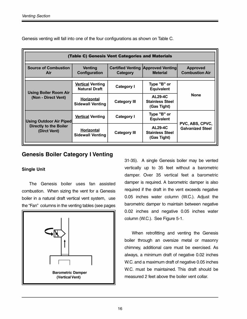
Genesis venting will fall into one of the four configurations as shown on Table C.
(Table C) Genesis Vent Categories and Materials
Source of CombustionAir
VentingConfiguration
Certified VentingCategory
Approved VentingMeterial
ApprovedCombustion Air
Using Boiler Room Air(Non - Direct Vent)
Vertical VentingNatural Draft
Category IType "B" orEquivalent
NoneHorizontal
Sidewall VentingCategory III
AL29-4CStainless Steel
(Gas Tight)
Using Outdoor Air PipedDirectly to the Boiler
(Dirct Vent)
Vertical Venting Category IType "B" orEquivalent
PVC, ABS, CPVC,Galvanized Steel Horizontal
Sidewall VentingCategory III
AL29-4CStainless Steel
(Gas Tight)

Genesis Engineering and Design Manual
17
Natural Draft Vertical Venting Using Boiler Room Air for Combustion(Category I)
Genesis is usingBoiler Room AirFor Combustion
(Table D) Genesis Natural Draft Vertical Vent
Model #Vent Size
(Inch)Certified Venting
CategoryApproved Venting
Material
Max. Distance W/OBarometric Damper /
With Barometric
GB/GW-300 5 Category IType "B" orEquivalent
35' / To Roof
GB/GW-400 thruGB/GW-500
6 Category IType "B" orEquivalent
35' / To Roof
GB/GW-650 thruGB/GW-750
8 Category IType "B" orEquivalent
35' / To Roof
GB/GW-1000 10 Category IType "B" orEquivalent
35' / To Roof
GB/GW-1300 thruGB/GW-1500
12 Category IType "B" orEquivalent
35' / To Roof
GB/GW-1850 thruGB/GW-2100
14 Category IType "B" orEquivalent
35' / To Roof
GB/GW-2500 16 Category IType "B" orEquivalent
35' / To Roof
Figure 5-2 - Natural Draft Vertical Venting
18
Venting Section
Masonry Chimneys - AtmosphericDraft
A masonry chimney must be properly sized
for the installation of any gas fired appliance.
Exterior masonry chimneys with one or more
sides exposed to cold outdoor temperatures are
more likely to have venting problems. The
temperature of the flue products from a mid
efficiency appliance may not be able to sufficiently
heat the masonry structure of the chimney to
generate proper draft. This will result in
condensing of flue products, damage of the
masonry flue tile, insufficient draft, and possible
spillage of flue products into an occupied living
space.
Very tall and or large chimneys may have
excessively high and hard to control draft,
resulting in poor combustion, nuisance control
lockouts, overheating of the combustion chamber,
and premature boiler failure.
Carefully inspect all chimney systems during
the project design phase. If there is any doubt
about the sizing or condition of a masonry
chimney, reline the chimney with a properly sized
and approved chimney liner system. Metal liner
systems Type "B" double wall or flexible metallic
liners are recommended. Consult with local code
officials to determine code requirements.
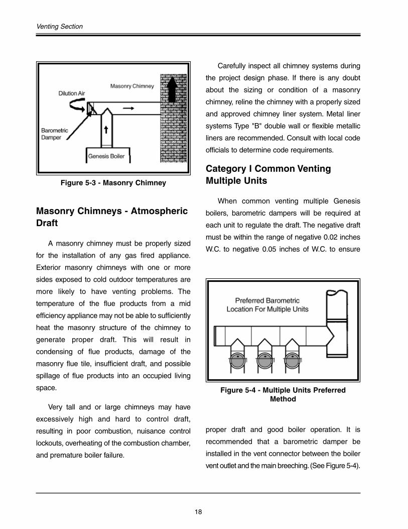
Category I Common VentingMultiple Units
When common venting multiple Genesis
boilers, barometric dampers will be required at
each unit to regulate the draft. The negative draft
must be within the range of negative 0.02 inches
W.C. to negative 0.05 inches of W.C. to ensure
proper draft and good boiler operation. It is
recommended that a barometric damper be
installed in the vent connector between the boiler
vent outlet and the main breeching.(See Figure 5-4).
Figure 5-3 - Masonry Chimney
Figure 5-4 - Multiple Units Preferred Method
Genesis Engineering and Design Manual
19
If ceiling heights are restricted and it is not
possible to install the barometric damper in the
vent connector, install a barometric damper in the
breeching between each appliance as shown in
Figure 5-5.
If it is not possible to install individual
barometric dampers as previously discussed
then install a single large barometric damper equal
to the main breeching. This large barometric
damper must be installed between the last
appliance in the vent and the chimney see Figure
5-6.
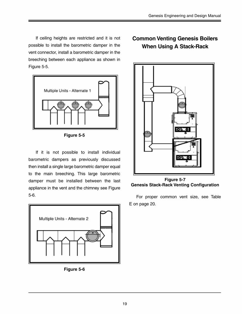
Common Venting Genesis BoilersWhen Using A Stack-Rack
For proper common vent size, see Table
E on page 20.
Figure 5-5
Figure 5-6
Figure 5-7Genesis Stack-Rack Venting Configuration
20
Venting Section
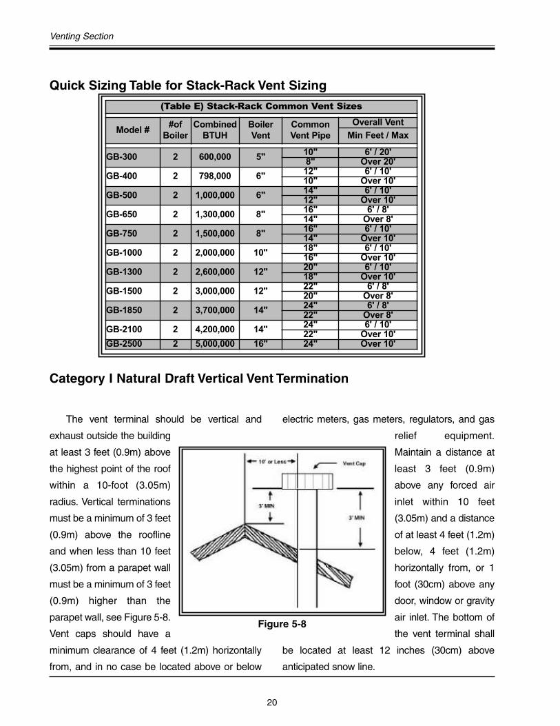
Quick Sizing Table for Stack-Rack Vent Sizing
The vent terminal should be vertical and
exhaust outside the building
at least 3 feet (0.9m) above
the highest point of the roof
within a 10-foot (3.05m)
radius. Vertical terminations
must be a minimum of 3 feet
(0.9m) above the roofline
and when less than 10 feet
(3.05m) from a parapet wall
must be a minimum of 3 feet
(0.9m) higher than the
parapet wall, see Figure 5-8.
Vent caps should have a
minimum clearance of 4 feet (1.2m) horizontally
from, and in no case be located above or below
electric meters, gas meters, regulators, and gas
relief equipment.
Maintain a distance at
least 3 feet (0.9m)
above any forced air
inlet within 10 feet
(3.05m) and a distance
of at least 4 feet (1.2m)
below, 4 feet (1.2m)
horizontally from, or 1
foot (30cm) above any
door, window or gravity
air inlet. The bottom of
the vent terminal shall
be located at least 12 inches (30cm) above
anticipated snow line.
Category I Natural Draft Vertical Vent Termination
(Table E) Stack-Rack Common Vent Sizes
Model ##of
BoilerCombined
BTUHBoilerVent
CommonVent Pipe
Overall Vent
Min Feet / Max
GB-300 2 600,000 5" 10" 6' / 20'8" Over 20'
GB-400 2 798,000 6" 12" 6' / 10'10" Over 10'
GB-500 2 1,000,000 6" 14" 6' / 10'12" Over 10'
GB-650 2 1,300,000 8" 16" 6' / 8'14" Over 8'
GB-750 2 1,500,000 8" 16" 6' / 10'14" Over 10'
GB-1000 2 2,000,000 10" 18" 6' / 10'16" Over 10'
GB-1300 2 2,600,000 12" 20" 6' / 10'18" Over 10'
GB-1500 2 3,000,000 12" 22" 6' / 8'20" Over 8'
GB-1850 2 3,700,000 14" 24" 6' / 8'22" Over 8'
GB-2100 2 4,200,000 14" 24" 6' / 10'22" Over 10'
GB-2500 2 5,000,000 16" 24" Over 10'
Figure 5-8

Genesis Engineering and Design Manual
21
Figure 5-9 Figure 5-10
Category I Vertical Venting(Two Pipe System Using Outdoor Air)
Notes:90° elbows = 10 equivalent feet of piping.45° elbows = 5 equivalent feet of piping.
(Table F) Vertical Direct Vent
Model #VentSize
(Inch)
CertifiedVenting
Category
ApprovedVentingMaterial
Max.Equivelent
Feet of
Combustion Air IntakePipe Size
ApprovedCombustion Air Intake
Max.Equivelent
Feet of
GB-300 5 Category I Type "B" or 60' 5 Galvanized 60'
GB-400 thru 6 Category I Type "B" or 35' 6 Galvanized 35'
GB-650 thru 8 Category I Type "B" or 35' 8 Galvanized 35'
GB-1000 10 Category I Type "B" or 35' 8 Galvanized 35'
GB-1300 thru 12 Category I Type "B" or 35' 10 Galvanized 35'
GB-1850 14 Category I Type "B" or 20' 10 Galvanized 20'
GB-2100 14 Category I Type "B" or 20' 12 Galvanized 20'
GB-2500 16 Category I Type "B" or 20' 12 Galvanized 20'
22
Venting Section
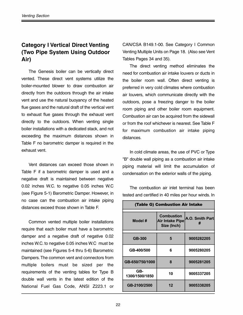
Category I Vertical Direct Venting(Two Pipe System Using OutdoorAir)
The Genesis boiler can be vertically direct
vented. These direct vent systems utilize the
boiler-mounted blower to draw combustion air
directly from the outdoors through the air intake
vent and use the natural buoyancy of the heated
flue gases and the natural draft of the vertical vent
to exhaust flue gases through the exhaust vent
directly to the outdoors. When venting single
boiler installations with a dedicated stack, and not
exceeding the maximum distances shown in
Table F no barometric damper is required in the
exhaust vent.
Vent distances can exceed those shown in
Table F if a barometric damper is used and a
negative draft is maintained between negative
0.02 inches W.C. to negative 0.05 inches W.C
(see Figure 5-1) Barometric Damper. However, in
no case can the combustion air intake piping
distances exceed those shown in Table F.
Common vented multiple boiler installations
require that each boiler must have a barometric
damper and a negative draft of negative 0.02
inches W.C. to negative 0.05 inches W.C must be
maintained (see Figures 5-4 thru 5-6) Barometric
Dampers.The common vent and connectors from
multiple boilers must be sized per the
requirements of the venting tables for Type B
double wall vents in the latest edition of the
National Fuel Gas Code, ANSI Z223.1 or
CAN/CSA B149.1-00. See Category I Common
Venting Multiple Units on Page 18. (Also see Vent
Tables Pages 34 and 35).
The direct venting method eliminates the
need for combustion air intake louvers or ducts in
the boiler room wall. Often direct venting is
preferred in very cold climates where combustion
air louvers, which communicate directly with the
outdoors, pose a freezing danger to the boiler
room piping and other boiler room equipment.
Combustion air can be acquired from the sidewall
or from the roof whichever is nearest. See Table F
for maximum combustion air intake piping
distances.
In cold climate areas, the use of PVC or Type
"B" double wall piping as a combustion air intake
piping material will limit the accumulation of
condensation on the exterior walls of the piping.
The combustion air inlet terminal has been
tested and certified in 40 miles per hour winds. In
(Table G) Combustion Air Intake
Model #Combustion
Air Intake PipeSize (Inch)
A.O. Smith Part#
GB-300 5 9005282205
GB-400/500 6 9005280205
GB-650/750/1000 8 9005281205
GB-1300/1500/1850
10 9005337205
GB-2100/2500 12 9005338205

Genesis Engineering and Design Manual
23
accordance with CSA, A. O. Smith must supply
this approved combustion air inlet terminal fitting.
See Table G for the Approved Inlet Termination
Kit #.
Meeting Special State and LocalCodes Requiring Direct VentSealed Combustion
As noted in the previous Vertical Direct
Venting Section, when venting the Genesis boiler
in a vertical venting configuration the natural draft
provides a negative category I vent that generally
allows the use of type “B” vent pipe for most
applications. However, some local and state
codes require Direct Vent Sealed Combustion
when meeting certain boiler room fire ratings and
construction requirements. One such state is
Wisconsin.
Genesis boilers have sealed combustion
chambers and meet the requirements of these
codes when gas tight venting material and air tight
combustion air intake piping is used. To meet
these special code requirements all venting
material must be AL29-4C stainless steel gas tight
venting material and all combustion air intake
piping must be PVC with all joints glued and
sealed. The venting distances for this direct vent
sealed combustion configuration are the same
as those shown in (Table F) only the venting and
combustion air piping materials change. Common
venting in this configuration is not allowed.
Code requires that the manufacturer supply
the combustion air intake and exhaust vent
terminations. Table G2 provides the part numbers
for the Vertical Direct Vent Kits.
Table G2 Vertical Direct Venting Kits
Model #Vent Outlet Pipe
Size (Inch)Combustion Air
Inlet Pipe Size (Inch)A.O. Smith Part #
GB-300 5 5 9003671001
GB-400/500 6 6 9003671002
GB-650/750 8 8 9003671003
GB-1000 10 8 9003679000
GB-1300/1500 12 10 9003679001
GB-1850 14 10 9003679004
GB-2100 14 12 9003679002
GB-2500 16 12 9003679003

24
Venting Section
Category III One Pipe Sidewall Venting Using Boiler Room Air
Notes: 90° elbows = 10 equivalent feet of piping.45° elbows = 5 equivalent feet of piping.For distances greater than those shown: See extended venting section.
Figure 5-11
(Table H) Single Pipe Sidewall Venting
Model #Vent Size
(Inch)Certified Venting
CategoryApproved Venting
Material
Max.Equivelent
Feet of Vent
GB-300 5 Category IIIAL29-4C StainlessSteel (Gas Tight)
110'
GB-400 thru GB-500 6 Category IIIAL29-4C StainlessSteel (Gas Tight)
50'
GB-650 thru GB-750 8 Category IIIAL29-4C StainlessSteel (Gas Tight)
50'
GB-1000 10 Category IIIAL29-4C StainlessSteel (Gas Tight)
70'
GB-1300 thru GB-1500
12 Category IIIAL29-4C StainlessSteel (Gas Tight)
70'
GB-1850 thru GB-2100
14 Category IIIAL29-4C StainlessSteel (Gas Tight)
40'
GB-2500 16 Category IIIAL29-4C StainlessSteel (Gas Tight)
40'

Genesis Engineering and Design Manual
25
Category III One Pipe SidewallVenting Using Boiler Room Air
When venting the Genesis boiler horizontally in
a Category III configuration AL29-4C, stainless
steel exhaust vent material must be used to prevent
the corrosive condensate from damaging the
venting. A condensate tee and drain line must be
installed in the horizontal run of the vent as close
to the boiler as possible in order to drain the
condensate. See Figure 5-12. For locating the vent
termination, see page 29 “Locating Exhaust and
Combustion Air Terminations.”
The A. O. Smith exhaust vent termination is
the only AGA/CGA approved termination for the
Genesis boiler. The kits include exhaust vent
termination, condensate tee, and condensate
drain tubing. This exhaust vent terminal has been
tested and certified in 40 mph winds. See Table I.
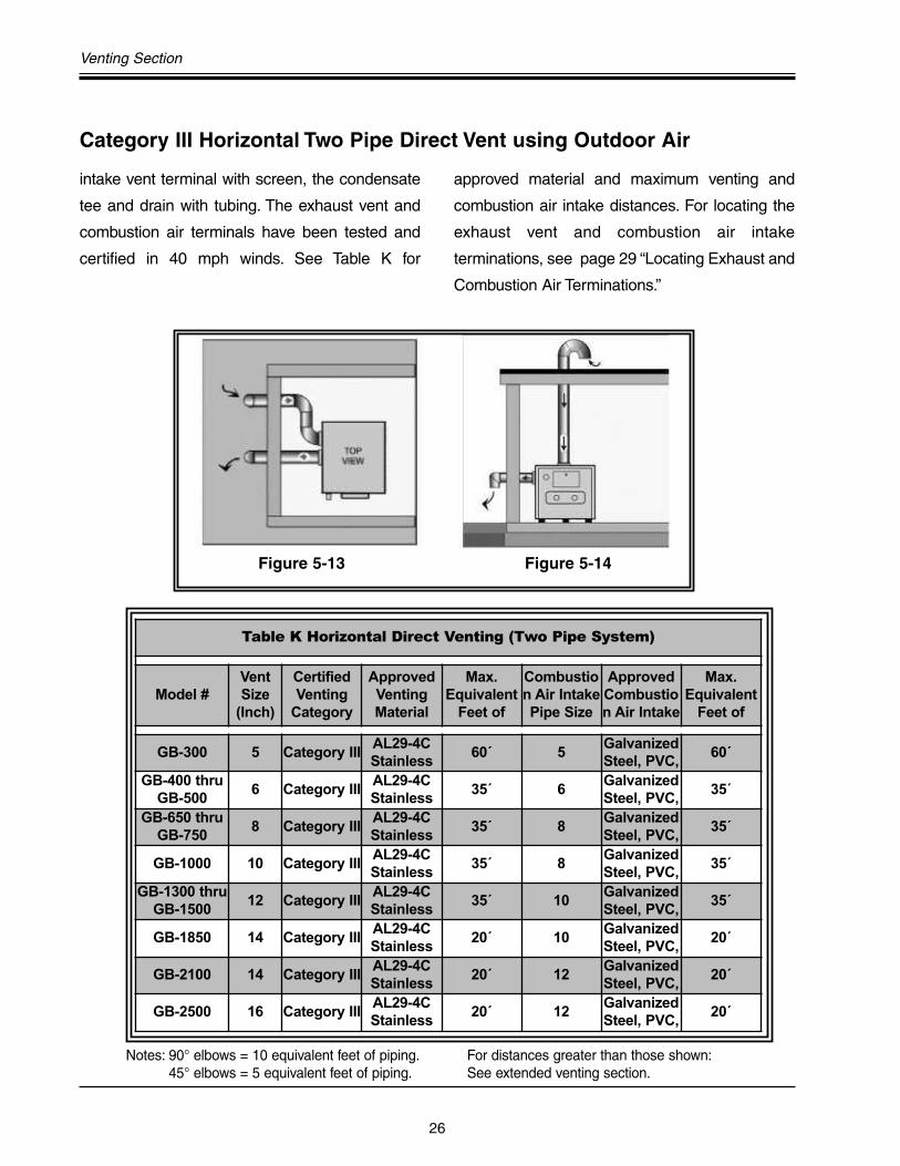
Category III Horizontal Two PipeDirect Vent using Outdoor Air
When venting the Genesis boiler in a two-
pipe direct vent application using outdoor air (See
Figures 5-13 & 5-14), use Table J to select the
approved direct vent kit. These kits include the
appropriate exhaust vent terminal, the PVC ell
Figure 5-12
(Table I) Sidewall Vent Kit
Model #Vent OutletPipe Size
(Inch)
A.O. Smith Part#
GB-300 5 9003672001
GB-400/500 6 9003672002
GB-650/750 8 9003672003
GB-1000 10 9003682000
GB-1300/1500 12 9003682001
GB-1850/2100 14 9003682002
GB-2500 16 9003682003
(Table J) Horizontal Direct Venting Kits
Model #Vent OutletPipe Size
(Inch)
Combustion Air InletPipe Size
A.O. SmithPart #
GB-300 5 5 9003672001
GB-400/500 6 6 9003672002
GB-650/750 8 8 9003672003
GB-1000 10 8 9003680002
GB-1300/1500 12 10 9003680000
GB-1850 14 10 9003680001
GB-2100 14 12 9500007282
GB-2500 16 12 9500007283
26
Venting Section
intake vent terminal with screen, the condensate
tee and drain with tubing. The exhaust vent and
combustion air terminals have been tested and
certified in 40 mph winds. See Table K for
approved material and maximum venting and
combustion air intake distances. For locating the
exhaust vent and combustion air intake
terminations, see page 29 “Locating Exhaust and
Combustion Air Terminations.”
Notes: 90° elbows = 10 equivalent feet of piping.45° elbows = 5 equivalent feet of piping.
For distances greater than those shown:See extended venting section.
Category III Horizontal Two Pipe Direct Vent using Outdoor Air
Figure 5-13 Figure 5-14
Table K Horizontal Direct Venting (Two Pipe System)
Model #VentSize
(Inch)
CertifiedVenting
Category
ApprovedVentingMaterial
Max.Equivalent
Feet of
Combustion Air IntakePipe Size
ApprovedCombustion Air Intake
Max.Equivalent
Feet of
GB-300 5 Category IIIAL29-4CStainless
60´ 5GalvanizedSteel, PVC,
60´
GB-400 thruGB-500
6 Category IIIAL29-4CStainless
35´ 6GalvanizedSteel, PVC,
35´
GB-650 thruGB-750
8 Category IIIAL29-4CStainless
35´ 8GalvanizedSteel, PVC,
35´
GB-1000 10 Category IIIAL29-4CStainless
35´ 8GalvanizedSteel, PVC,
35´
GB-1300 thruGB-1500
12 Category IIIAL29-4CStainless
35´ 10GalvanizedSteel, PVC,
35´
GB-1850 14 Category IIIAL29-4CStainless
20´ 10GalvanizedSteel, PVC,
20´
GB-2100 14 Category IIIAL29-4CStainless
20´ 12GalvanizedSteel, PVC,
20´
GB-2500 16 Category IIIAL29-4CStainless
20´ 12GalvanizedSteel, PVC,
20´
Genesis Engineering and Design Manual
27
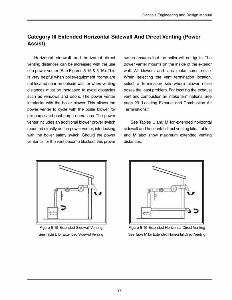
Horizontal sidewall and horizontal direct
venting distances can be increased with the use
of a power venter (See Figures 5-15 & 5-16).This
is very helpful when boiler/equipment rooms are
not located near an outside wall, or when venting
distances must be increased to avoid obstacles
such as windows and doors. The power venter
interlocks with the boiler blower. This allows the
power venter to cycle with the boiler blower for
pre-purge and post-purge operations. The power
venter includes an additional blower prover switch
mounted directly on the power venter, interlocking
with the boiler safety switch. Should the power
venter fail or the vent become blocked, this prover
switch ensures that the boiler will not ignite. The
power venter mounts on the inside of the exterior
wall. All blowers and fans make some noise.
When selecting the vent termination location,
select a termination site where blower noise
poses the least problem. For locating the exhaust
vent and combustion air intake terminations. See
page 29 “Locating Exhaust and Combustion Air
Terminations.”
See Tables L and M for extended horizontal
sidewall and horizontal direct venting kits. Table L
and M also show maximum extended venting
distances.
Figure 5-15 Extended Sidewall Venting
See Table L for Extended Sidewall Venting
Figure 5-16 Extended Horizontal Direct Venting
See Table M for Extended Horizontal Direct Venting
Category III Extended Horizontal Sidewall And Direct Venting (PowerAssist)
28
Venting Section
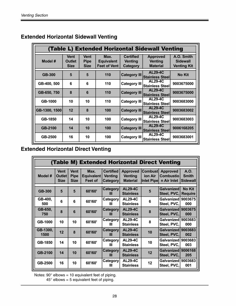
Extended Horizontal Sidewall Venting
Extended Horizontal Direct Venting
Notes: 90° elbows = 10 equivalent feet of piping.45° elbows = 5 equivalent feet of piping.
(Table L) Extended Horizontal Sidewall Venting
Model #Vent
OutletSize
VentPipeSize
Max.Equivalent
Feet of Vent
CertifiedVenting
Category
ApprovedVentingMaterial
A.O. SmithSidewall
Venting Kit
GB-300 5 5 110 Category IIIAL29-4C
Stainless SteelNo Kit
GB-400, 500 6 6 110 Category IIIAL29-4C
Stainless Steel9003675000
GB-650, 750 8 6 110 Category IIIAL29-4C
Stainless Steel9003675000
GB-1000 10 10 110 Category IIIAL29-4C
Stainless Steel9003683000
GB-1300, 1500 12 8 100 Category IIIAL29-4C
Stainless Steel9003683002
GB-1850 14 10 100 Category IIIAL29-4C
Stainless Steel9003683003
GB-2100 14 10 100 Category IIIAL29-4C
Stainless Steel9006168205
GB-2500 16 10 100 Category IIIAL29-4C
Stainless Steel9003683001
(Table M) Extended Horizontal Direct Venting
Model #Vent
OutletSize
VentPipeSize
Max.Equivalent
Feet of
CertifiedVenting
Category
ApprovedVentingMaterial
Combustion Air
Inlet Pipe
ApprovedCombustion Air Inlet
A.O.Smith
Sidewall
GB-300 5 5 60'/60'Category
IIIAL29-4CStainless
5GalvanizedSteel, PVC,
No KitRequire
GB-400,500
6 6 60'/60'Category
IIIAL29-4CStainless
6GalvanizedSteel, PVC,
9003675000
GB-650,750
8 6 60'/60'Category
IIIAL29-4CStainless
8GalvanizedSteel, PVC,
9003675000
GB-1000 10 10 60'/60'Category
IIIAL29-4CStainless
8GalvanizedSteel, PVC,
9003683000
GB-1300,1500
12 8 60'/60'Category
IIIAL29-4CStainless
10GalvanizedSteel, PVC,
9003683002
GB-1850 14 10 60'/60'Category
IIIAL29-4CStainless
10GalvanizedSteel, PVC,
9003683003
GB-2100 14 10 60'/60'Category
IIIAL29-4CStainless
12GalvanizedSteel, PVC,
9006168205
GB-2500 16 10 60'/60'Category
IIIAL29-4CStainless
12GalvanizedSteel, PVC,
9003683001
Genesis Engineering and Design Manual
29
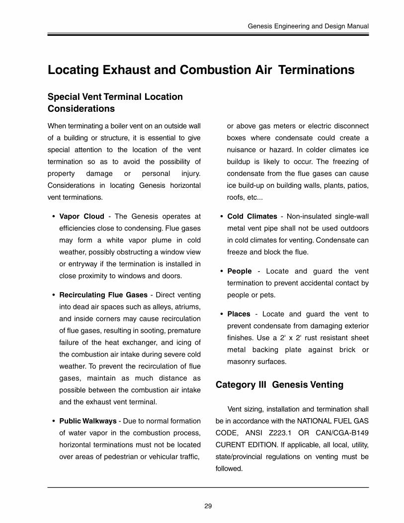
When terminating a boiler vent on an outside wall
of a building or structure, it is essential to give
special attention to the location of the vent
termination so as to avoid the possibility of
property damage or personal injury.
Considerations in locating Genesis horizontal
vent terminations.
• Vapor Cloud - The Genesis operates at
efficiencies close to condensing. Flue gases
may form a white vapor plume in cold
weather, possibly obstructing a window view
or entryway if the termination is installed in
close proximity to windows and doors.
• Recirculating Flue Gases - Direct venting
into dead air spaces such as alleys, atriums,
and inside corners may cause recirculation
of flue gases, resulting in sooting, premature
failure of the heat exchanger, and icing of
the combustion air intake during severe cold
weather. To prevent the recirculation of flue
gases, maintain as much distance as
possible between the combustion air intake
and the exhaust vent terminal.
• Public Walkways - Due to normal formation
of water vapor in the combustion process,
horizontal terminations must not be located
over areas of pedestrian or vehicular traffic,
or above gas meters or electric disconnect
boxes where condensate could create a
nuisance or hazard. In colder climates ice
buildup is likely to occur. The freezing of
condensate from the flue gases can cause
ice build-up on building walls, plants, patios,
roofs, etc...
• Cold Climates - Non-insulated single-wall
metal vent pipe shall not be used outdoors
in cold climates for venting. Condensate can
freeze and block the flue.
• People - Locate and guard the vent
termination to prevent accidental contact by
people or pets.
• Places - Locate and guard the vent to
prevent condensate from damaging exterior
finishes. Use a 2' x 2' rust resistant sheet
metal backing plate against brick or
masonry surfaces.
Category III Genesis Venting
Vent sizing, installation and termination shall
be in accordance with the NATIONAL FUEL GAS
CODE, ANSI Z223.1 OR CAN/CGA-B149
CURENT EDITION. If applicable, all local, utility,
state/provincial regulations on venting must be
followed.
Locating Exhaust and Combustion Air Terminations
Special Vent Terminal LocationConsiderations

30
Venting Section
• Vent must terminate at least four (4) feet
below, four (4) feet horizontally, or one (1)
foot above any door, window or gravity air
inlet to the building.
• The vent must not be less than seven (7)
feet above grade when located adjacent to
public walkways.
• Terminate vent at least three (3) feet above
any forced air inlet located within ten (10) feet.
• Vent must terminate at least four (4) feet
horizontally, and in no case above or below
unless four (4) feet horizontal distance is
maintained, from electric meters, gas meters,
regulators, and relief equipment.
• The minimum distance from the exhaust
terminal to an inside corner formed by two
exterior walls is 6 feet but 10 feet is
recommended where possible.
• Maintain a minimum distance of 4 feet from
any soffit or eave vent to the exhaust terminal.
• To prevent recirculation of flue gases from
an adjacent vent cap, the point of termination
for the combustion air inlet terminal must be
at least 3 feet (0.91m) below and 3 feet
(0.91m) away from the exhaust vent cap, if it
is located within 10' (3.05m) of the exhaust
vent cap. Remember that these are the
minimum distances, additional distance is
recommended when possible.
• The exhaust and intake air termination must
be a minimum of 12 inches above anticipated
snow or grade level, which ever is higher.
Figure 5-17 Termination Locations
Termination Considerations

Genesis Engineering and Design Manual
31
TYPE “B” DOUBLE WALL VENT
SIZING TABLES
32
Vent Tables
Type B Gas Vent Diameter, Inches
HeightH (ft)
LateralL (ft)
4˝ 5˝ 6˝ 7˝ 8˝ 10˝
Appliance Input Rating in Thousands of BTU Per Hour
Fan NatMax
Fan NatMax
Fan NatMax
Fan NatMax
Fan NatMax
Fan NatMaxMin Max Min Max Min Max Min Max Min Max Min Max
6 0 0 152 86 0 251 141 0 375 205 0 524 285 0 698 370 0 1121 570
2 18 97 67 27 157 105 32 232 157 44 321 217 53 425 285 75 675 455
4 30 94 64 39 153 103 50 227 153 66 316 211 79 419 279 110 668 445
6 36 91 61 47 149 100 59 223 149 78 310 205 93 413 273 128 661 435
8 0 0 165 94 0 276 155 0 415 235 0 583 320 0 780 415 0 1261 660
2 16 109 75 25 178 120 28 263 180 42 365 247 50 483 322 71 770 515
5 32 103 71 42 171 115 53 255 173 70 356 237 83 473 313 115 758 503
8 39 98 66 51 164 109 64 247 165 84 347 227 99 463 303 137 746 490
10 0 0 175 100 0 295 166 0 447 255 0 631 345 0 847 450 0 1377 720
2 17 118 81 23 194 129 26 289 195 40 402 273 48 533 355 68 852 560
5 32 113 77 41 187 124 52 280 188 68 392 263 81 522 346 112 839 547
10 41 104 70 54 176 115 67 267 175 88 376 245 204 504 330 142 817 525
15 0 0 191 112 0 327 187 0 502 285 0 716 390 0 970 525 0 1596 840
2 15 136 93 20 226 150 22 339 225 38 475 316 45 633 414 63 1019 675
5 30 130 87 39 219 142 49 330 217 64 463 300 76 620 403 105 1003 660
10 40 121 82 51 206 135 64 315 208 84 445 288 99 600 386 135 977 635
15 48 112 76 61 195 128 76 301 198 98 429 275 115 580 373 155 953 610
20 0 0 202 119 0 349 202 0 540 307 0 776 430 0 1057 575 0 1756 930
2 14 149 100 18 250 166 20 377 249 33 531 346 41 711 470 59 1150 755
5 29 143 96 38 242 160 47 367 241 62 519 337 73 697 460 101 1133 738
10 38 133 89 50 229 150 62 351 228 81 499 321 95 675 443 130 1105 710
15 46 124 84 59 217 142 73 337 217 94 481 308 111 654 427 150 1078 688
20 55 116 78 69 206 134 84 322 206 107 464 295 125 634 410 167 1052 665
30 0 0 213 128 0 374 220 0 587 336 0 853 475 0 1173 650 0 1977 1060
2 13 166 112 14 283 185 18 432 280 27 613 394 33 826 535 54 1351 865
5 28 160 108 36 275 176 45 421 273 58 600 385 69 811 524 96 1332 851
10 37 150 102 48 262 171 59 405 261 77 580 371 91 788 507 125 1301 829
15 44 141 96 57 249 163 70 389 249 90 560 357 105 765 490 143 1272 807
20 53 132 90 66 237 154 80 374 237 102 542 343 119 743 473 160 1243 784
30 73 113 NR 88 214 NR 104 346 219 131 507 321 149 702 444 195 1189 745
50 0 0 216 134 0 397 232 0 633 363 0 932 518 0 1297 708 0 2231 1195
2 11 183 122 14 320 206 15 497 314 22 715 445 26 975 615 41 1620 1010
5 27 177 119 35 312 200 43 487 308 55 702 438 65 960 605 90 1600 996
10 35 168 114 45 299 190 56 471 298 73 681 426 86 935 589 118 1567 972
15 42 158 NR 54 287 180 66 455 288 85 662 413 100 911 572 136 1536 948
20 50 149 NR 63 275 169 76 440 278 97 642 401 113 888 556 151 1505 924
30 69 131 NR 84 250 NR 99 410 259 123 605 376 141 844 522 183 1446 876
100 0 0 218 NR 0 407 NR 0 665 400 0 997 560 0 1411 770 0 2491 1310
2 10 194 NR 12 354 NR 13 566 375 18 831 510 21 1155 700 30 1975 1170
5 26 189 NR 33 347 NR 40 557 369 52 820 504 60 1141 692 82 1955 1159
10 33 182 NR 43 335 NR 53 542 361 68 801 493 80 1118 679 108 1923 1142
15 40 174 NR 50 321 NR 62 528 353 80 782 482 93 1095 666 126 1892 1124
20 47 166 NR 59 311 NR 71 513 344 90 763 471 105 1073 653 141 1861 1107
30 NR NR NR 78 290 NR 92 483 NR 115 726 449 131 1029 627 170 1802 1071
50 NR NR NR NR NR NR 147 428 NR 180 651 405 197 944 575 241 1688 1000
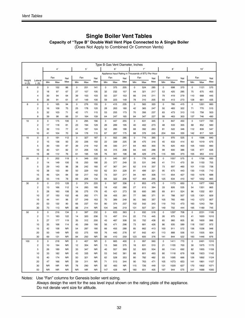
Single Boiler Vent TablesCapacity of “Type B” Double Wall Vent Pipe Connected to A Single Boiler
(Does Not Apply to Combined Or Common Vents)
Notes: Use “Fan” columns for Genesis boiler vent sizing.Always design the vent for the sea level input shown on the rating plate of the appliance.Do not derate vent size for altitude.

Genesis Engineering and Design Manual
33
Type B Gas Vent Diameter, Inches
HeightH (ft)
LateralL (ft)
12˝ 14˝ 16˝ 18˝ 20˝ 22˝ 24˝
Appliance Input Rating in Thousands of BTU Per Hour
Fan NatMax
Fan NatMax
Fan NatMax
Fan NatMax
Fan NatMax
Fan NatMax
Fan NatMaxMin Max Min Max Min Max Min Max Min Max Min Max Min Max
6 0 0 1645 850 0 2267 1170 0 2983 1530 0 3802 1960 0 4721 2430 0 5737 2950 0 6853 3520
2 103 982 650 138 1346 890 178 1769 1170 225 2250 1480 296 2782 1850 360 3377 2220 426 4030 2670
4 147 975 640 191 1338 880 242 1761 1160 300 2242 1475 390 2774 1835 469 3370 2215 555 4023 2660
6 171 967 630 219 1330 870 276 1753 1150 341 2235 1470 437 2767 1820 523 3363 2210 618 4017 2650
8 0 0 1858 970 0 2571 1320 0 3399 1740 0 4333 2220 0 5387 2750 0 6555 3360 0 7838 4010
2 98 1124 745 130 1543 1020 168 2030 1340 212 2584 1700 278 3196 2110 336 3882 2560 401 4634 3050
5 154 1110 733 199 1528 1010 251 2013 1330 311 2563 1685 398 3180 2090 476 3863 2545 562 4612 3040
8 180 1097 720 231 1514 1000 289 2000 1320 354 2552 1670 450 3163 2070 537 3850 2530 630 4602 3030
10 0 0 2036 1060 0 2825 1450 0 3742 1925 0 4782 2450 0 5955 3050 0 7254 3710 0 8682 4450
2 93 1244 850 124 1713 1130 161 2256 1480 202 2868 1890 264 3556 2340 319 4322 2840 378 5153 3390
5 149 1229 829 192 1696 1105 243 2238 1461 300 2849 1871 382 3536 2318 458 4301 2818 540 5132 3371
10 187 1204 795 238 1669 1040 298 2209 1430 364 2818 1840 459 3504 2280 546 4268 2780 641 5099 3340
15 0 0 2380 1240 0 3323 1720 0 4423 2270 0 5678 2900 0 7099 3620 0 8665 4410 0 10393 5300
2 86 1495 985 114 2062 1350 147 2719 1770 186 3467 2260 239 4304 2800 290 5232 3410 346 6251 4080
5 140 1476 967 182 2041 1327 229 2696 1748 283 3442 2235 355 4278 2777 426 5204 3385 501 6222 4057
10 177 1446 936 227 2009 1289 283 2659 1712 346 3402 2193 432 4234 2739 510 5159 3343 599 6175 4019
15 202 1418 905 257 1976 1250 318 2623 1675 385 3363 2150 479 4192 2700 564 5115 3300 665 6129 3980
20 0 0 2637 1350 0 3701 1900 0 4948 2520 0 6376 3250 0 7988 4060 0 9785 4980 0 11753 6000
2 81 1694 1100 107 2343 1520 139 3097 2000 175 3955 2570 220 4916 3200 269 5983 3910 321 7154 4700
5 135 1674 1079 174 2320 1498 219 3071 1978 270 3926 2544 337 4885 3174 403 5950 3880 475 7119 4662
10 172 1641 1045 220 2282 1460 273 3029 1940 334 3880 2500 413 4835 3130 489 5896 3830 573 7063 4600
15 195 1609 1018 248 2245 1425 306 2988 1910 372 3835 2465 459 4786 3090 541 5844 3795 631 7007 4575
20 217 1578 990 273 2210 1390 335 2948 1880 404 3791 2430 495 4737 3050 585 5792 3760 689 6953 4550
30 0 0 3004 1550 0 4252 2170 0 5725 2920 0 7420 3770 0 9341 4750 0 11483 5850 0 13848 7060
2 74 2004 1310 98 2786 1800 127 3696 2380 159 4734 3050 199 5900 3810 241 7194 4650 285 8617 5600
5 127 1981 1289 164 2759 1775 206 3666 2350 252 4701 3020 312 5863 3783 373 7155 4622 439 8574 5552
10 164 1944 1254 209 2716 1733 259 3617 2300 316 4647 2970 386 5803 3739 456 7090 4574 535 8505 5471
15 187 1908 1220 237 2674 1692 292 3570 2250 354 4594 2920 431 5744 3695 507 7026 4527 590 8437 5391
20 207 1873 1185 260 2633 1650 319 3523 2200 384 4542 2870 467 5686 3650 548 6964 4480 639 8370 5310
30 246 1807 1130 305 2555 1585 369 3433 2130 440 4442 2785 540 5574 3565 635 6842 4375 739 8239 5225
50 0 0 3441 1825 0 4934 2550 0 6711 3440 0 8774 4460 0 11129 5635 0 13767 6940 0 16694 8430
2 66 2431 1513 86 3409 2125 113 4554 2840 141 5864 3670 171 7339 4630 209 8980 5695 251 10788 6860
5 188 2406 1495 151 3380 2102 191 4520 2813 234 5826 3639 283 7295 4597 336 8933 5654 394 10737 6818
10 154 2366 1466 196 3332 2064 243 4464 2767 295 5763 3585 355 7224 4542 419 8855 5585 491 10652 6749
15 177 2327 1437 222 3285 2026 274 4409 2721 330 5701 3534 396 7155 4511 465 8779 5546 542 10570 6710
20 195 2288 1408 244 3239 1987 300 4356 2675 361 5641 3481 433 7086 4479 506 8704 5506 586 10488 6670
30 232 2214 1349 287 3150 1910 347 4253 2631 412 5523 3431 494 6953 4421 577 8557 5444 672 10328 6603
100 0 0 3925 2050 0 5729 2950 0 7914 4050 0 10485 5300 0 13454 6700 0 16817 8600 0 20578 10300
2 44 3027 1820 72 4313 2550 95 5834 3500 120 7591 4600 138 9577 5800 169 11803 7200 204 14264 8800
5 107 3002 1803 136 4282 2531 172 5797 3475 206 7548 4566 245 9528 5769 293 11748 7162 341 14204 8756
10 142 2961 1775 180 4231 2500 223 5737 3434 268 7478 4509 318 9447 5717 374 11658 7100 436 14105 8683
15 163 2920 1747 206 4182 2469 252 5678 3392 304 7409 4451 358 9367 5665 418 11569 7037 487 14007 8610
20 181 2880 1719 226 4133 2438 277 5619 3351 330 7341 4394 387 9289 5613 452 11482 6975 523 13910 8537
30 215 2803 1663 265 4037 2375 319 5505 3267 378 7209 4279 446 9136 5509 514 11310 6850 592 13720 8391
50 292 2657 1550 350 3856 2250 415 5289 3100 486 6956 4050 572 8841 5300 659 10979 6600 752 13354 8100
Single Boiler Vent TablesCapacity of “Type B” Double Wall Vent Pipe Connected to A Single Boiler
(Does Not Apply to Combined Or Common Vents)
Notes: Use “Fan” columns for Genesis boiler vent sizing.Always design the vent for the sea level input shown on the rating plate of the appliance.Do not derate vent size for altitude.

34
Vent Tables
Multiple Boiler Common Vent Tables
Type B Gas Vent Diameter, Inches
VentHeight H (ft)
Connector Rise R (ft)
3˝ 4˝ 5˝ 6˝ 7˝ 8˝ 10˝Appliance Input Rating in Thousands of BTU Per Hour
Fan NatMax
Fan NatMax
Fan NatMax
Fan NatMax
Fan NatMax
Fan NatMax
Fan NatMaxMin Max Min Max Min Max Min Max Min Max Min Max Min Max
6 1 22 37 26 35 66 46 46 106 72 58 164 104 77 225 142 92 296 185 128 466 289
2 23 41 31 37 75 55 48 121 86 60 183 124 79 253 168 95 333 220 131 526 345
3 24 44 35 38 81 62 49 132 96 62 199 139 82 275 189 97 363 248 134 575 386
8 1 22 40 27 35 72 48 49 114 76 64 176 109 84 243 148 100 320 194 138 507 303
2 23 44 32 36 80 57 51 128 90 66 195 129 86 269 175 103 356 230 141 564 358
3 24 47 36 37 87 64 53 139 101 67 210 145 88 290 198 105 384 258 143 612 402
10 1 22 43 28 34 78 50 49 123 78 65 189 113 89 257 154 106 341 200 146 542 314
2 23 47 33 36 86 59 51 136 93 67 206 134 91 282 182 109 374 238 149 596 372
3 24 50 37 37 92 67 52 146 104 69 220 150 94 303 205 111 402 268 152 642 417
15 1 21 50 30 33 89 53 47 142 83 64 220 120 88 298 163 110 389 214 162 609 333
2 22 53 35 35 96 63 49 153 99 66 235 142 91 320 193 112 419 253 165 658 394
3 24 55 40 36 102 71 51 163 111 68 248 160 93 339 218 115 445 286 167 700 444
20 1 21 54 31 33 99 56 46 157 87 62 246 125 86 334 171 107 436 224 158 681 347
2 22 57 37 34 105 66 48 167 104 64 259 149 89 354 202 110 463 265 161 725 414
3 23 60 42 35 110 74 50 176 116 66 271 168 91 371 228 113 486 300 164 764 466
30 1 20 62 33 31 113 53 45 181 93 60 288 134 83 391 182 103 512 238 151 802 372
2 21 64 39 33 118 70 47 190 110 62 299 158 85 408 215 105 535 282 155 840 439
3 22 66 44 34 123 79 48 198 124 64 309 178 88 423 242 108 555 317 158 874 494
50 1 19 71 36 30 133 64 43 216 101 57 349 145 79 477 197 97 627 257 144 984 403
2 21 73 43 32 137 76 45 223 119 59 358 172 81 490 234 100 645 306 148 1014 478
3 22 75 48 33 141 86 46 229 134 61 366 194 83 502 263 103 661 343 151 1043 538
100 1 18 82 37 28 158 66 40 262 104 53 442 150 73 611 204 91 810 266 135 1285 417
2 19 83 44 30 161 79 42 267 123 55 447 178 75 619 242 94 822 316 139 1306 494
3 20 84 50 31 163 89 44 272 138 57 452 200 78 627 272 97 834 355 142 1327 555
Type B Gas Vent Diameter, Inches
VentHeight H
(ft)
4˝ 5˝ 6˝ 7˝ 8˝ 10˝
Combined Appliance Input Rating in Thousands of BTU Per Hour
Fan + Fan
Fan + Nat
Nat + Nat
Fan + Fan
Fan + Nat
Nat + Nat
Fan + Fan
Fan + Nat
Nat + Nat
Fan + Fan
Fan + Nat
Nat + Nat
Fan + Fan
Fan + Nat
Nat + Nat
Fan + Fan
Fan + Nat
Nat + Nat
6 92 81 65 140 116 103 204 161 147 309 248 200 404 314 260 672 520 410
8 101 90 73 155 129 114 224 178 163 339 275 223 444 348 290 740 577 465
10 110 97 79 169 141 124 243 194 178 367 299 242 477 377 315 800 627 495
15 125 112 91 195 164 144 283 228 206 427 352 280 556 444 365 924 733 565
20 136 123 102 215 183 160 314 255 229 475 394 310 621 499 405 1035 826 640
30 152 138 118 244 210 185 361 297 266 547 459 360 720 585 470 1209 975 740
50 167 153 134 279 244 214 421 353 310 641 547 423 854 706 550 1451 1188 860
100 175 163 NR 311 277 NR 489 421 NR 751 658 479 1025 873 625 1784 1502 975
Note: Use the above table to size vent connector (the pipe between the appliance and the common vent).
Notes: Use “Fan” columns for Genesis boiler vent sizing.Always design the vent for the sea level input shown on the rating plate of the appliance.Do not derate vent size for altitude.Use Fan + Fan when all appliances are fan assisted.Use Fan + Natural when fan assisted and draft hood equipment are commonly vented together.Use Nat + Nat when all appliances are drafthood type equipment.
Vent Connector Table
Common Vent Table

Genesis Engineering and Design Manual
35
Multiple Boiler Common Vent Tables
Type B Gas Vent Diameter, Inches
VentHeight H (ft)
ConnectorRise R (ft)
12˝ 14˝ 16˝ 18˝ 20˝ 22˝ 24˝Appliance Input Rating in Thousands of BTU Per Hour
Fan NatMax
Fan NatMax
Fan NatMax
Fan NatMax
Fan NatMax
Fan NatMax
Fan NatMaxMin Max Min Max Min Max Min Max Min Max Min Max Min Max
6 2 174 764 496 223 1046 653 281 1371 853 346 1772 1080 NA NA NA NA NA NA NA NA NA
4 180 897 616 230 1231 827 287 1617 1081 352 2069 1370 NA NA NA NA NA NA NA NA NA
6 NA NA NA NA NA NA NA NA NA NA NA NA NA NA NA NA NA NA NA NA NA
8 2 186 822 516 238 1126 696 298 1478 910 365 1920 1150 NA NA NA NA NA NA NA NA NA
4 192 952 644 244 1307 884 305 1719 1150 372 2211 1460 471 2737 1800 560 3319 2180 662 3957 2590
6 198 1050 772 252 1445 1072 313 1902 1390 380 2434 1770 478 3018 2180 568 3665 2640 669 4373 3130
10 2 196 870 536 249 1195 730 311 1570 955 379 2049 1205 NA NA NA NA NA NA NA NA NA
4 201 997 664 256 1371 924 318 1804 1205 387 2332 1535 486 2887 1890 581 3502 2280 636 4175 2710
6 207 1095 792 263 1509 1118 325 1989 1455 395 2556 1865 494 3169 2290 589 3849 2760 694 4593 3270
15 2 214 967 568 272 1334 790 336 1760 1030 408 2317 1305 NA NA NA NA NA NA NA NA NA
4 221 1085 712 279 1499 1006 344 1978 1320 416 2579 1665 523 3197 2060 624 3881 2490 734 4631 2960
6 228 1181 856 286 1632 1222 351 2157 1610 424 2796 2025 533 3470 2510 634 4216 3030 743 5035 3600
20 2 223 1051 596 291 1443 840 357 1911 1095 430 2533 1385 NA NA NA NA NA NA NA NA NA
4 230 1162 748 298 1597 1064 365 2116 1395 438 2778 1765 554 3447 2180 661 4190 2630 772 5005 3130
6 237 1253 900 307 1726 1288 373 2287 1695 450 2984 2145 567 3708 2650 671 4511 3190 785 5392 3790
30 2 216 1217 632 286 1664 910 367 2183 1190 461 2891 1540 NA NA NA NA NA NA NA NA NA
4 223 1316 792 294 1802 1160 376 2366 1510 474 3110 1920 619 3840 2365 728 4681 2860 847 5606 3410
6 231 1400 952 303 1920 1410 384 2524 1830 485 3299 2340 632 4080 2875 741 4976 3480 860 5961 4150
50 2 203 1479 689 273 2023 1007 350 2659 1315 435 3548 1665 NA NA NA NA NA NA NA NA NA
4 213 1561 860 281 2139 1291 359 2814 1685 447 3730 2135 580 4601 2633 709 5569 3185 851 6633 3790
6 221 1631 1031 290 2242 1575 369 2951 2055 461 3893 2605 594 4808 3208 724 5826 3885 867 6943 4620
100 2 192 1923 712 254 2644 1050 326 3490 1370 402 4707 1740 NA NA NA NA NA NA NA NA NA
4 200 1984 888 263 2731 1346 336 3606 1760 414 4842 2220 523 5982 2750 639 7254 3330 769 8650 3950
6 208 2035 1064 272 2811 1642 346 3714 2150 426 4968 2700 539 6143 3350 654 7453 4070 786 8892 4810
Type B Gas Vent Diameter, Inches
VentHeight H
(ft)
12˝ 14˝ 16˝ 18˝ 20˝ 22˝ 24˝
Combined Appliance Input Rating in Thousands of BTU Per Hour
Fan + Fan
Fan + Nat
Nat + Nat
Fan + Fan
Fan + Nat
Nat + Nat
Fan + Fan
Fan + Nat
Nat + Nat
Fan + Fan
Fan + Nat
Nat + Nat
Fan + Fan
Fan + Nat
Nat + Nat
Fan + Fan
Fan + Nat
Nat + Nat
Fan + Fan
Fan + Nat
Nat + Nat
6 900 696 588 1284 990 815 1735 1336 1065 2253 1732 1345 2838 2180 1660 3488 2677 1970 4206 3226 2390
8 994 773 652 1423 1103 912 1927 1491 1190 2507 1936 1510 3162 2439 1860 3890 2998 2200 4695 3616 2680
10 1076 841 712 1542 1200 995 2093 1625 1300 2727 2113 1645 3444 2665 2030 4741 3278 2400 5123 3957 2920
15 1247 986 825 1794 1410 1158 2440 1910 1510 3184 2484 1910 4026 3133 2360 4971 3862 2790 6016 4670 3400
20 1405 1116 916 2006 1588 1290 2722 2147 1690 3561 2798 2140 4548 3552 2640 5573 4352 3120 6749 5261 3800
30 1658 1327 1025 2373 1892 1525 3220 2558 1990 4197 3326 2520 5303 4193 3110 6539 5157 3680 7940 6247 4480
50 2024 1640 1280 2911 2347 1863 3964 3183 2430 5184 4149 3075 6567 5240 3800 8116 6458 4500 9837 7813 5475
100 2569 2131 1670 3732 3076 2450 5125 4202 3200 6749 5509 4050 8597 6986 5000 10681 8648 5920 13004 10499 7200
Note: Use the above table to size vent connector (the pipe between the appliance and the common vent).
Notes: Use “Fan” columns for Genesis boiler vent sizing.Always design the vent for the sea level input shown on the rating plate of the appliance.Do not derate vent size for altitude.Use Fan + Fan when all appliances are fan assisted.Use Fan + Natural when fan assisted and draft hood equipment are commonly vented together.Use Nat + Nat when all appliances are drafthood type equipment.
Vent Connector Table
Common Vent Table

36
Genesis Engineering and Design Manual
37
General Genesis Gas SupplyConsiderations
All gas supply piping connections to the
Genesis boiler(s) shall be installed in accordance
with the latest editions of the National Fuel Gas
Code, ANSI Z223.1 or in Canada CAN/CGA-
B149.1-00. In addition, any applicable local gas
company or municipality code requirements must
be met.
It is recommended that a drip leg and a
manual gas shutoff valve with pressure test plug
be installed in the gas piping supply line.
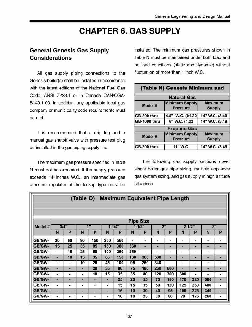
The maximum gas pressure specified in Table
N must not be exceeded. If the supply pressure
exceeds 14 inches W.C., an intermediate gas
pressure regulator of the lockup type must be
installed. The minimum gas pressures shown in
Table N must be maintained under both load and
no load conditions (static and dynamic) without
fluctuation of more than 1 inch W.C.
The following gas supply sections cover
single boiler gas pipe sizing, multiple appliance
gas system sizing, and gas supply in high altitude
situations.
CHAPTER 6. GAS SUPPLY
(Table O) Maximum Equivalent Pipe Length
Model #Pipe Size
3/4" 1" 1-1/4" 1-1/2" 2" 2-1/2" 3"N P N P N P N P N P N P N P
GB/GW- 30 60 90 150 250 560 - - - - - - - -GB/GW- 15 25 35 85 150 380 360 - - - - - - -GB/GW- - 15 25 60 100 260 250 - - - - - - -GB/GW- - 10 15 35 65 150 130 360 500 - - - - -GB/GW- - - 10 25 45 100 95 250 340 - - - -GB/GW- - - - 20 35 80 75 180 260 600 - - - -GB/GW- - - - 10 15 35 35 80 120 300 300 - - -GB/GW- - - - - - 25 20 55 75 180 170 325 560 -GB/GW- - - - - - 15 15 35 50 120 125 250 400 -GB/GW- - - - - - 15 10 30 40 95 100 225 340 -GB/GW- - - - - - 10 10 25 30 80 70 175 260 -
(Table N) Genesis Minimum and
Natural Gas
Model # Minimum Supply
Pressure Maximum
Supply
GB-300 thru 4.5" W.C. (01.22 14" W.C. (3.49GB-1000 thru 6" W.C. (1.22 14" W.C. (3.49
Propane Gas
Model # Minimum Supply
Pressure Maximum
Supply
GB-300 thru 11" W.C. 14" W.C. (3.49

38
Gas Supply
Table O provides the correct pipe size for the
individual Genesis boiler based on the number of
equivalent feet of piping from the gas supply meter
to the boiler. The chart allows for the average
number of pipe fittings. Where it is necessary to
use more, use one pipe size larger than specified
to compensate for any increased pressure drop.
A complete gas supply system (meter, pipings,
valves, regulators, etc.) should be sized for all
appliances connected to the system. Ensure
that the system is capable of maintaining a steady
non-fluctuating gas pressure with all connected
gas appliances firing.
Single Boiler Gas Pipe Sizing
When sizing for multiple boilers use Table P
for natural gas systems and Table Q for propane
gas systems. These tables show the BTU/H gas
capacity for iron pipe at specified distances.
When sizing multiple boiler systems, the common
pipe (starting at the meter) must be sized for the
maximum capacity of all appliances connected to
the system. As the system progresses and each
appliance is connected, the pipe size must be re-
evaluated and resized if necessary for the
demand.
Gas System Sizing
(Table P) Maximum Capacity of Pipe in Thousands of BTU'sPer Hour
of 0.5"
NorminalIron Pipe
Size
Length of Pipe (Feet)
10 20 30 40 50 60 70 80 90 100 125 150 175 200
1 697 477 384 328 292 267 256 246 210 200 179 164 149 138
1 1/4 1,400 974 789 677 595 543 502 472 441 410 369 333 308 287
1 1/2 2,150 1,500 1,210 1,020 923 830 769 707 666 636 564 513 472 441
2 4,100 2,820 2,260 1,950 1,720 1,560 1,440 1,330 1,250 1,180 1,100 974 871 820
2 1/2 6,460 4,460 3,610 3,100 2,720 2,460 2,310 2,100 2,000 1,900 1,700 1,540 1,400 1,300
3 11,20 7,900 6,400 5,400 4,870 4,410 4,000 3,800 3,540 3,300 3,000 2,720 2,500 2,340
4 23,50 16,10 13,10 11,10 10,00 9,000 8,300 7,690 7,380 6,870 6,150 5,640 5,130 4,720
Genesis Engineering and Design Manual
39
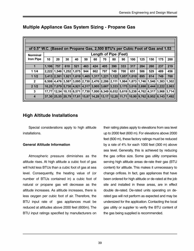
Special considerations apply to high altitude
installations.
General Altitude Information
Atmospheric pressure diminishes as the
altitude rises. At high altitude a cubic foot of gas
will hold less BTUs than a cubic foot of gas at sea
level. Consequently, the heating value of (or
number of BTUs contained in) a cubic foot of
natural or propane gas will decrease as the
altitude increases. As altitude increases, there is
less oxygen per cubic foot of air. Therefore, the
BTU input rate of gas appliances must be
reduced at altitudes above 2000 feet (600m). The
BTU input ratings specified by manufacturers on
their rating plates apply to elevations from sea level
up to 2000 feet (600 m). For elevations above 2000
feet (600 m), these factory ratings must be reduced
by a rate of 4% for each 1000 feet (300 m) above
sea level. Generally, this is achieved by reducing
the gas orifice size. Some gas utility companies
serving high altitude areas de-rate their gas (BTU
content) for altitude. This makes it unnecessary to
change orifices. In fact, gas appliances that have
been ordered for high altitude or de-rated at the job
site and installed in these areas, are in effect
double de-rated. De-rated units operating on de-
rated gas will not perform as expected and may be
undersized for the application. Contacting the local
gas utility or supplier to verify the BTU content of
the gas being supplied is recommended.
Multiple Appliance Gas System Sizing - Propane Gas
High Altitude Installations
of 0.5" W.C. (Based on Propane Gas, 2,500 BTU's per Cubic Foot of Gas and 1.53
NorminalIron Pipe
Length of Pipe (Feet)10 20 30 40 50 60 70 80 90 100 125 150 175 200
1 1,106 757 610 521 463 424 405 390 333 317 284 260 237 219
1 1/4 2,222 1,546 1,252 1,075 944 862 797 749 700 651 586 529 489 456
1 1/2 3,413 2,381 1,921 1,619 1,465 1,317 1,221 1,122 1,057 1,010 895 814 749 700
2 6,508 4,476 3,587 3,095 2,730 2,476 2,286 2,111 1,984 1,873 1,746 1,546 1,383 1,302
2 1/2 10,25 7,079 5,730 4,921 4,317 3,905 3,667 3,333 3,175 3,016 2,698 2,444 2,222 2,063
3 17,77 12,54 10,15 8,571 7,730 7,000 6,349 6,032 5,619 5,238 4,762 4,317 3,968 3,714
4 37,30 25,55 20,79 17,61 15,87 14,28 13,17 12,20 11,71 10,90 9,762 8,952 8,143 7,492

40
Gas Supply
Because the boiler is being derated for high
altitude, boilers installed in high altitude areas are
often mistakenly undersized. When sizing a boiler
for a high altitude application, the boilers BTU
input should be increased at a rate equal to the
altitude de-rate.
Genesis Pre-Jet Orifices
Genesis boilers (Series 200 and up) are
equipped with unique Pre-Jet orifices. These
orfices are self-regulating for high altitude
installations up to 5,000 feet. (Consult the factory
for higher altitudes).
Example: A Genesis boiler is rated at 750,000
Btu/hr. input at sea level. At an altitude of 5,000
(1500m), the Pre-Jet orifices will decrease the
input rate by 4% for every 1,000 feet (300m) to a
new rating of 611,530 BTU/H (750,000 x .96 x .96
x .96 x .96 x .96 = 611,530) The input reduction is
achieved by the Pre-Jet orifices through self-
regulation. Remember, the input/output rating of
the boiler is being reduced by close to 20%.
When initially sizing the boiler, its size must also
be increased by about 20% to compensate for the
higher altitude.
High Altitude Sizing Considerations
Figure 6-1 Pre-Jet Orifice

Genesis Engineering and Design Manual
41
Electrical connections to the Genesis must
comply with the following codes:
• National Electrical Code
• Electrical grounding as required by N.E.C.
NFPA 70-latest edition.
• In Canada, C.S.A. C22. 1 C.E.C. Part 1.
• Any other state, provincial or local codes or
regulations having jurisdiction.
All electrical connections for the Genesis
boiler are made at the 4x4 boxes located on the
rear of the boiler. (See Figure 1-1 on Page 4.)
These 4x4 electrical junction boxes provide
connections for:
• 120V power supply
• earth ground
• remote tank temperature probe
• alternate 24V thermostat
• 120V secondary pump connections
The 120-volt pump connections are for
secondary pumps in hydronic-heating systems.
The pump connections can handle up to a
maximum of a 1/3 hp pump on Genesis models
GB-200 thru 750, and up to a maximum of a 1 hp
pump on Genesis models GB-1000 thru 2500.
Even larger pumps can be used with an optional
relay, consult the factory for assistance.
Electrical Requirements
The Genesis must be connected to a single-
phase 120 VAC, 60 Hz, 20 or 30 Amp
independent line source on a dedicated breaker
and run in a dedicated conduit. The Genesis is
polarity sensitive and has to be wired correctly. (A
green LED located on the Control Board verifies
correct polarity.) The boiler also must be properly
grounded.
Do not share the breaker to the boiler with
other appliances. Do not share Neutral or Ground
wires between boilers or with other appliances.
Each Genesis Boiler should have a dedicated hot,
neutral and ground wire installed in a dedicated
conduit to that boiler.
Temperature sensor wiring or external 24 VAC
control wiring also must be installed in its own
dedicated conduit to guard against EMI.
EMI and RFI (EMI = electro-magnetic
interference; RFI = radio frequency interference),
also known as “line noise,” can cause erratic boiler
operation. If this condition is suspected, an
electrical line filter/conditioner (available from
electrical suppliers) may be necessary to
eliminate line noise interference.
CHAPTER 7. GENESIS ELECTRICALREQUIREMENTS

42
Genesis Electrical Requirements
Solid state controls are vulnerable to damage
from electrical spikes in the power supply. A
commercial-grade surge protection device should
be installed.
Genesis boilers are available with optional dry
contacts for:
• any boiler failure
• combustion air louvers
• power venters and draft inducers
(Table R) Genesis Electrical Requirements
Model # Volts/Hz Amperes
GB-200 thru 750 120/60 20
GB-1000 thru 2500 120/60 30
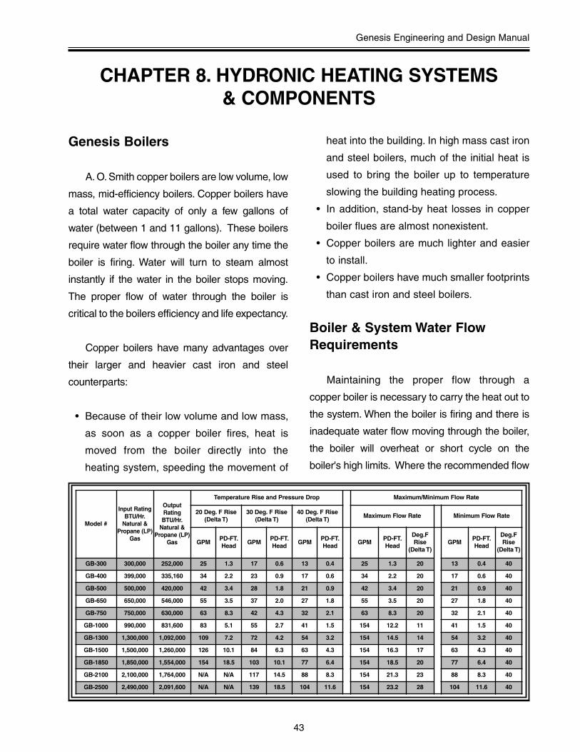
Genesis Engineering and Design Manual
43
Genesis Boilers
A. O. Smith copper boilers are low volume, low
mass, mid-efficiency boilers. Copper boilers have
a total water capacity of only a few gallons of
water (between 1 and 11 gallons). These boilers
require water flow through the boiler any time the
boiler is firing. Water will turn to steam almost
instantly if the water in the boiler stops moving.
The proper flow of water through the boiler is
critical to the boilers efficiency and life expectancy.
Copper boilers have many advantages over
their larger and heavier cast iron and steel
counterparts:
• Because of their low volume and low mass,
as soon as a copper boiler fires, heat is
moved from the boiler directly into the
heating system, speeding the movement of
heat into the building. In high mass cast iron
and steel boilers, much of the initial heat is
used to bring the boiler up to temperature
slowing the building heating process.
• In addition, stand-by heat losses in copper
boiler flues are almost nonexistent.
• Copper boilers are much lighter and easier
to install.
• Copper boilers have much smaller footprints
than cast iron and steel boilers.
Boiler & System Water FlowRequirements
Maintaining the proper flow through a
copper boiler is necessary to carry the heat out to
the system. When the boiler is firing and there is
inadequate water flow moving through the boiler,
the boiler will overheat or short cycle on the
boiler's high limits. Where the recommended flow
Model #
Input RatingBTU/Hr.
Natural &Propane (LP)
Gas
OutputRatingBTU/Hr.
Natural &Propane (LP)
Gas
Temperature Rise and Pressure Drop Maximum/Minimum Flow Rate
20 Deg. F Rise(Delta T)
30 Deg. F Rise(Delta T)
40 Deg. F Rise(Delta T)
Maximum Flow Rate Minimum Flow Rate
GPMPD-FT.Head
GPMPD-FT.Head
GPMPD-FT.Head
GPMPD-FT.Head
Deg.FRise
(Delta T)GPM
PD-FT.Head
Deg.FRise
(Delta T)
GB-300 300,000 252,000 25 1.3 17 0.6 13 0.4 25 1.3 20 13 0.4 40
GB-400 399,000 335,160 34 2.2 23 0.9 17 0.6 34 2.2 20 17 0.6 40
GB-500 500,000 420,000 42 3.4 28 1.8 21 0.9 42 3.4 20 21 0.9 40
GB-650 650,000 546,000 55 3.5 37 2.0 27 1.8 55 3.5 20 27 1.8 40
GB-750 750,000 630,000 63 8.3 42 4.3 32 2.1 63 8.3 20 32 2.1 40
GB-1000 990,000 831,600 83 5.1 55 2.7 41 1.5 154 12.2 11 41 1.5 40
GB-1300 1,300,000 1,092,000 109 7.2 72 4.2 54 3.2 154 14.5 14 54 3.2 40
GB-1500 1,500,000 1,260,000 126 10.1 84 6.3 63 4.3 154 16.3 17 63 4.3 40
GB-1850 1,850,000 1,554,000 154 18.5 103 10.1 77 6.4 154 18.5 20 77 6.4 40
GB-2100 2,100,000 1,764,000 N/A N/A 117 14.5 88 8.3 154 21.3 23 88 8.3 40
GB-2500 2,490,000 2,091,600 N/A N/A 139 18.5 104 11.6 154 23.2 28 104 11.6 40
CHAPTER 8. HYDRONIC HEATING SYSTEMS & COMPONENTS
44
Hydronic Heating Systems & Components
rates are maintained, smooth and efficient system
operation can be expected. (See Table S) for the
recommended Genesis boiler flow rates,
input/output, temperature rise (Delta T), and the
pressure drop through the boiler at the specified
flow rates.
There are many types of heating systems
such as: multiple boiler systems, process or
industrial systems, heat pump systems and etc.
The required flow rates of these systems do not
always match the boiler exactly. With these other
types of systems; pump sizing, pipe sizing, and
piping system design become more important.
Boiler Temperature Settings
A. O. Smith recommends a 20° to 40° Delta T
through the boiler. The boiler’s maximum
temperature setting (High Limit/ECO) is 240°F. A.
O. Smith recommends that the High Limit/ECO be
set 10° to 20° higher that the expected boiler
outlet water temperature. The expected boiler
outlet water temperature equals: The system set
point temperature plus the current boiler Delta T.
Setting the boiler’s High Limit/ECO too close to
the outlet water temperature will result in short
cycling and/or nuisance lockouts.
“A. O. Smith recommends that the High
Limit/ECO be set 10° to 20° higher than the
expected boiler outlet water temperature.The
expected boiler outlet water temperature
equals: The system set point temperature
plus the current boiler Delta T.”
Hydronic Heating SystemComponents
Expansion Tanks
All closed loop hydronic-heating systems
must include a properly sized and installed
expansion tank. Due to their ease of installation
and flexibility, diaphragm-type tanks are
recommended. The expansion tank should
always be installed on the suction side of the
pump.
Air Separator
All closed loop hydronic-heating systems
must include an air separator of adequate size
and capacity for the application. The air separator
removes air from the system by creating
turbulence and rapid pressure changes within the
unit. The air separator should have an automatic
air vent installed in the top of the air separator
device. The air separator should always be
installed on the suction side of the pump.
Automatic Air Vents
One automatic air vent is built into the top of
the air separator. In addition, automatic air vents
should be installed at the highest points of the
system and anywhere air may collect.

Genesis Engineering and Design Manual
45
Flow Switches & Low Water Cut-Offs
All A. O. Smith Genesis boilers are furnished
with a factory mounted and wired flow switch. A.
O. Smith requires a low water cut-off only when
the boiler is installed higher than the heating
system. Most codes and local authorities accept
the factory mounted flow switch in lieu of a low
water cut-off for low mass copper tube boilers
which require forced circulation. A. O. Smith does
offer optional factory installed and wired low water
cuts offs for all Genesis models. At no time can a
low water cut-off be used in lieu of the factory
installed flow switch.
Relief Valves
All A. O. Smith Genesis boilers are factory
equipped with an ASME code approved relief
valve as per ASME Boiler and Pressure Vessel
Code, Section IV “Heating Boilers.” All ASME
approved relief valves furnished by A. O. Smith
have a 50 psi pressure rating.
Dual Valve - Feed Water Regulator
A. O. Smith recommends that a feed water
regulator be installed and set at a minimum of 12
psi at the highest point of the system. Install a
check valve or back flow prevention device and a
manual shut off valve upstream of the regulator.
A. O. Smith recommends a dual valve feed water
make-up assembly that includes all of the above.

46
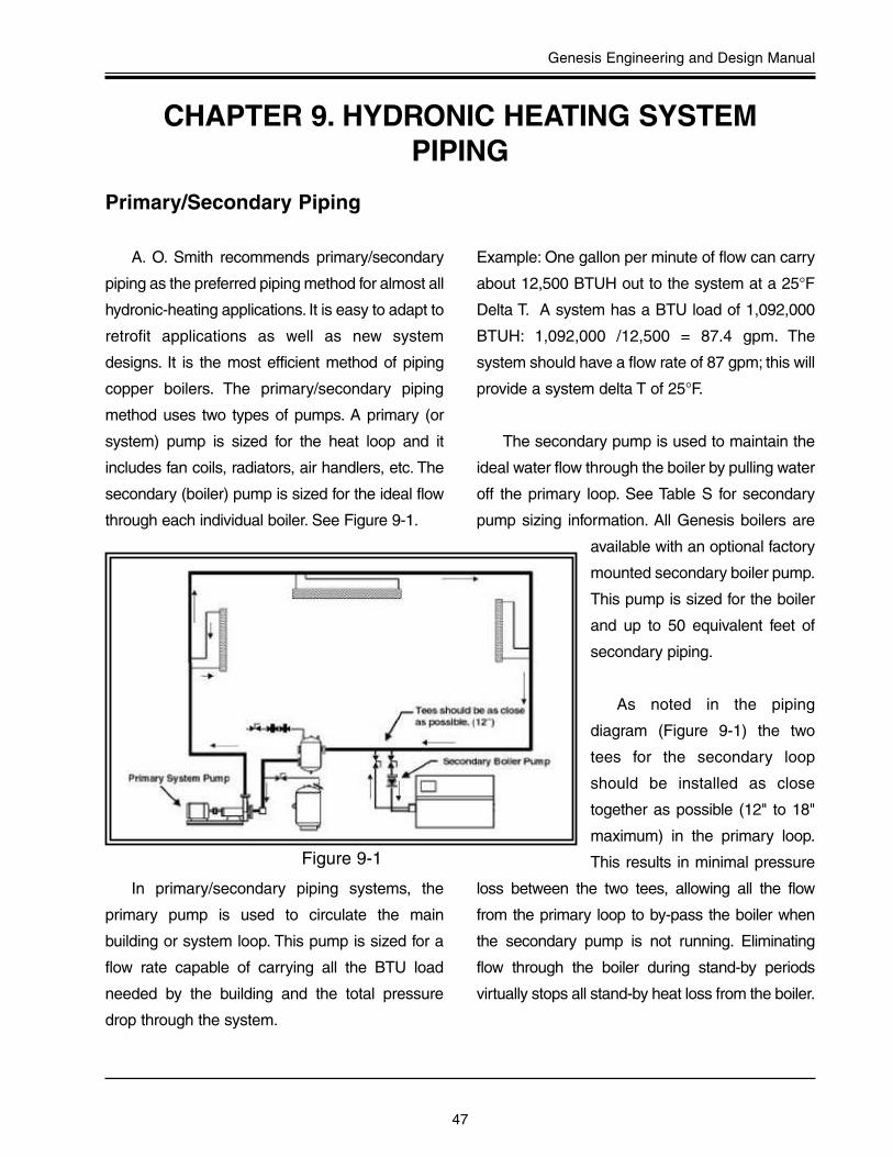
Genesis Engineering and Design Manual
47
A. O. Smith recommends primary/secondary
piping as the preferred piping method for almost all
hydronic-heating applications. It is easy to adapt to
retrofit applications as well as new system
designs. It is the most efficient method of piping
copper boilers. The primary/secondary piping
method uses two types of pumps. A primary (or
system) pump is sized for the heat loop and it
includes fan coils, radiators, air handlers, etc. The
secondary (boiler) pump is sized for the ideal flow
through each individual boiler. See Figure 9-1.
In primary/secondary piping systems, the
primary pump is used to circulate the main
building or system loop. This pump is sized for a
flow rate capable of carrying all the BTU load
needed by the building and the total pressure
drop through the system.
Example: One gallon per minute of flow can carry
about 12,500 BTUH out to the system at a 25°F
Delta T. A system has a BTU load of 1,092,000
BTUH: 1,092,000 /12,500 = 87.4 gpm. The
system should have a flow rate of 87 gpm; this will
provide a system delta T of 25°F.
The secondary pump is used to maintain the
ideal water flow through the boiler by pulling water
off the primary loop. See Table S for secondary
pump sizing information. All Genesis boilers are
available with an optional factory
mounted secondary boiler pump.
This pump is sized for the boiler
and up to 50 equivalent feet of
secondary piping.
As noted in the piping
diagram (Figure 9-1) the two
tees for the secondary loop
should be installed as close
together as possible (12" to 18"
maximum) in the primary loop.
This results in minimal pressure
loss between the two tees, allowing all the flow
from the primary loop to by-pass the boiler when
the secondary pump is not running. Eliminating
flow through the boiler during stand-by periods
virtually stops all stand-by heat loss from the boiler.
CHAPTER 9. HYDRONIC HEATING SYSTEM PIPING
Primary/Secondary Piping
Figure 9-1
48
Hydronic Heating System Piping
Note: Whenever hot water is pumped through a
non-firing boiler, it becomes, in effect, a water
cooler.
The Dia-Scan II boiler control, standard on all
Genesis models, has an integral pump control
with adjustable delay that allows the secondary
pump to run for a short period after each firing
cycle. For maximum system efficiency, this delay
cools the boiler down to an equal temperature
with the loop, removes any usable residual heat
left in the boiler, moves this usable heat out to the
system, and then turns the secondary pump off
thereby eliminating all stand-by heat loss up the
flue.
Primary/Secondary PipingMultiple Boilers
Primary/secondary piping is ideal for multiple
Genesis boiler applications. Multiple boiler
systems provide redundancy and are ideal for
those applications that cannot afford to be without
heat. Redundant systems allow units to be shut
down for service while other units are maintaining
the system.
Boilers are sized for the coldest day of the
year. On milder days, a single on/off fired boiler is
too big for the load and will short cycle. Short
cycling causes unnecessary wear on the boiler,
resulting in wide temperature swings and
decreased overall system efficiency.
Multiple boilers or multi-staged fired boilers
that size themselves to the demand are superior
to large single stage on/off units, providing higher
overall system efficiency.
Systems that employ four boilers have
proven to be the most efficient heating systems.
Four boilers, firing as four separate stages at 25%
increments allow maximum system control by
matching the BTU output of the boilers to the
current and ever changing system load. This
eliminates boiler short cycling and provides
maximum building comfort in all weather
conditions. Systems that utilize more than four
boilers (While providing extremely smooth
system operation, and often needed to meet
heavy BTU demands.) do not appear to offer any
clear additional energy savings.
Boiler Operating TemperatureControls
Single Boiler Systems
Fixed temperature single boiler systems can
be controlled by a simple aquastat installed in the
heating loop. If indoor/outdoor reset is required,
an electronic control is recommended. Do not use
the boiler’s internal high limit control as the
operating control. Always use a remote system
loop temperature control to operate any hydronic
heating system.

Genesis Engineering and Design Manual
49
Multiple Boiler Systems
A. O. Smith offers a line of optional Tekmar
controls for two, four, and eight boilers, which
provide both boiler sequencing and
indoor/outdoor reset. These controls are
recommended for multi-boiler systems. Tekmar
controls raise and lower the loop temperature
based on the outdoor temperature by cycling and
staging the boilers or the control can simply be set
to maintain a fixed loop set point temperature. By
maintaining the loop at the lowest temperature
possible while providing maximum building
comfort, these controls hold energy costs to a
minimum.
Systems should operate according to
temperature, not time. Energy Management
Systems (EMS) that bring on a single boiler
during a cold start and wait a fixed time to see if
the boiler can increase the loop temperature
before bringing on additional boilers are not
acceptable. During cold starts, all available boilers
should be firing.
Minimum System/BoilerTemperature
A. O. Smith recommends maintaining a
minimum boiler inlet water temperature of 120°F
on all Genesis products. Most hydronic heating
system applications will require much higher
operating temperatures. Systems using indoor/
outdoor reset controls/EMS Systems must be set
to prevent the system temperature from dropping
below the recommended minimum boiler inlet
water temperature.
Locating the System TemperatureSensor
Locating the system temperature sensor in
the supply side of the heating loop is typical in
systems with high flow rates, large water capacity,
and/or with controls that include wide
programmable differentials. However, in systems
with moderate flow or low water capacity, as
compared to the total system BTU input, boiler
short cycling can be expected.
To prevent short cycling in these applications,
A. O. Smith recommends locating the temperature
sensor in the system return. By sensing the return
water temperature, the boiler(s) see longer firing
times and longer off cycles. In this return location,
the system control will generally require a lower
temperature set point to achieve the desired outlet
water temperature. For example, a boiler
operating with a 180°F system design discharge
temperature and a 30°F Delta T will require a
150°F set point with the temperature sensor
located in the system return. The exact
temperature set point generally requires some
final adjustments at start-up when the system
reaches the desired operating temperature.
“In almost every case, copper boilers will
operate smoother and cycle less when the
system loop temperature sensor is installed
in the return piping.”
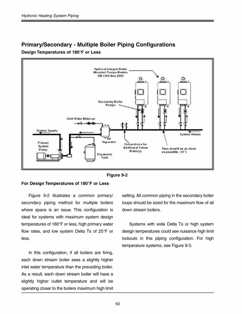
50
Hydronic Heating System Piping
Figure 9-2 illustrates a common primary/
secondary piping method for multiple boilers
where space is an issue. This configuration is
ideal for systems with maximum system design
temperatures of 180°F or less, high primary water
flow rates, and low system Delta Ts of 25°F or
less.
In this configuration, if all boilers are firing,
each down stream boiler sees a slightly higher
inlet water temperature than the preceding boiler.
As a result, each down stream boiler will have a
slightly higher outlet temperature and will be
operating closer to the boilers maximum high limit
setting. All common piping in the secondary boiler
loops should be sized for the maximum flow of all
down stream boilers.
Systems with wide Delta Ts or high system
design temperatures could see nuisance high limit
lockouts in this piping configuration. For high
temperature systems, see Figure 9-3.
Primary/Secondary - Multiple Boiler Piping ConfigurationsDesign Temperatures of 180°F or Less
For Design Temperatures of 180°F or Less
Figure 9-2

Genesis Engineering and Design Manual
51
A primary/secondary piping system using
a reverse return secondary boiler loop is illustrated
in Figure 9-3.This piping method is recommended
for systems with design temperatures over 180°F
and/or systems with Delta Ts up to 40°F.
In this piping method, each boiler sees the
same inlet water temperature coming from the
system return. All common piping in the
secondary boiler loops should be sized for the
maximum flow of all down stream boilers. It is very
important to carefully follow the primary/
secondary piping diagrams for reverse return
multiple boilers. The secondary tees need to be
as close together as possible. Ensure that there is
one long return run of common piping along the
full length of the boilers. Do not modify this piping
configuration.
Design Temperatures Over 180°F
For Design Temperatures Over 180°F
Figure 9-3 - Primary/Secondary Piping - Multiple Boilers Reverse Return

52
Hydronic Heating System Piping
For Design Temperatures Below 120°F
System designs that operate below 120°F
include closed loop water source heat pump
systems, low temperature industrial and
manufacturing applications, greenhouse plant
bed heating systems, snow melting systems, and
floor or slab heating. However, for systems
requiring lower loop temperatures, special design
considerations are required to prevent the
damaging effects of condensation on the boiler.
A low temperature primary/secondary-piping
configuration is illustrated in Figure 9-4.This piping
diagram is very similar to the basic primary/
secondary piping arrangement, but with the
addition of a by-pass and valve. By adjusting the
by-pass valve, heated outlet water from the boiler
is blended with cooler returning water and re-
circulated to the inlet of the boiler. This allows the
boiler to be operated internally at a higher non-
condensing temperature while maintaining the
desired lower loop temperature without damaging
condensation.
Design Temperatures Below 120°F
Figure 9-4 - Low Temperature System
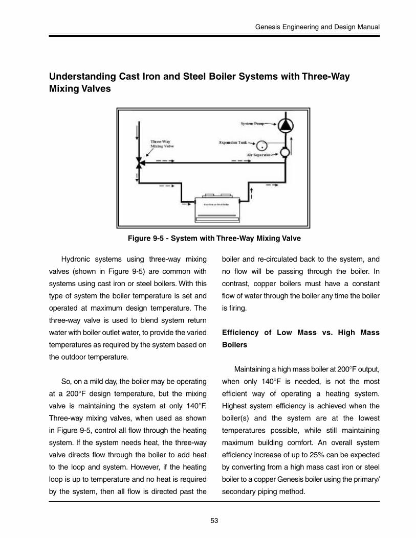
Genesis Engineering and Design Manual
53
Hydronic systems using three-way mixing
valves (shown in Figure 9-5) are common with
systems using cast iron or steel boilers. With this
type of system the boiler temperature is set and
operated at maximum design temperature. The
three-way valve is used to blend system return
water with boiler outlet water, to provide the varied
temperatures as required by the system based on
the outdoor temperature.
So, on a mild day, the boiler may be operating
at a 200°F design temperature, but the mixing
valve is maintaining the system at only 140°F.
Three-way mixing valves, when used as shown
in Figure 9-5, control all flow through the heating
system. If the system needs heat, the three-way
valve directs flow through the boiler to add heat
to the loop and system. However, if the heating
loop is up to temperature and no heat is required
by the system, then all flow is directed past the
boiler and re-circulated back to the system, and
no flow will be passing through the boiler. In
contrast, copper boilers must have a constant
flow of water through the boiler any time the boiler
is firing.
Efficiency of Low Mass vs. High Mass
Boilers
Maintaining a high mass boiler at 200°F output,
when only 140°F is needed, is not the most
efficient way of operating a heating system.
Highest system efficiency is achieved when the
boiler(s) and the system are at the lowest
temperatures possible, while still maintaining
maximum building comfort. An overall system
efficiency increase of up to 25% can be expected
by converting from a high mass cast iron or steel
boiler to a copper Genesis boiler using the primary/
secondary piping method.
Understanding Cast Iron and Steel Boiler Systems with Three-WayMixing Valves
Figure 9-5 - System with Three-Way Mixing Valve

54
Hydronic Heating System Piping
It is relatively easy to convert a high mass cast
iron or steel system with three way mixing valves
as shown in Figure 9-5 to a low mass
copper Genesis boiler system incorporating a
primary/secondary piping configuration.
Step 1. Remove the three-way mixing valve and
replace it with a short piece of pipe as shown in
Figure 9-6 - Step 1.
Step 2. Remove the boiler by-pass piping and
cap the boiler by-pass tee. See Figure
9-7 - Step 2.
Retrofitting A Cast Iron Boiler With Three-Way Mixing Valve To A CopperBoiler System
Figure 9-6 - Step 1 - Removing Mixing Valve
Figure 9-7 - Step 2 - Remove and Cap By-Pass Piping

Genesis Engineering and Design Manual
55
Step 3. Remove the old cast iron boiler.
Install a new piece of pipe with 3/4˝ stat
opening and two new tees between the old
boiler's system return or inlet piping and the
old boiler's outlet piping. This will complete
the primary loop. See Figure 9-8 Step 3.
Step 4. Install the new A. O. Smith copper
boiler and connect the boiler inlet and
outlets to the new tees. (As always, the
two tees should be as close as possible.)
This completes the secondary boiler loop.
The system conversion is now complete.
See Figure 9-9 for completed system view.
Figure 9-8 - Step 3 - Remove Old Cast Iron Boiler
Figure 9-9 - Step 4 - Install a New A. O. Smith Copper Boiler
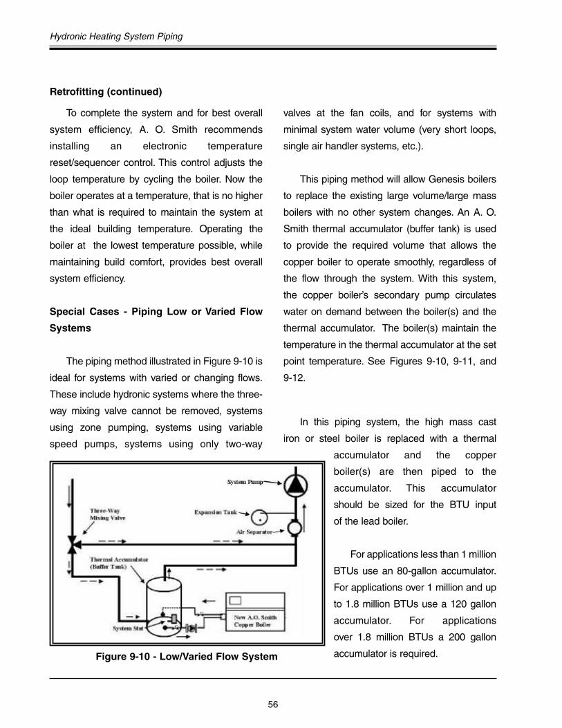
56
Hydronic Heating System Piping
To complete the system and for best overall
system efficiency, A. O. Smith recommends
installing an electronic temperature
reset/sequencer control. This control adjusts the
loop temperature by cycling the boiler. Now the
boiler operates at a temperature, that is no higher
than what is required to maintain the system at
the ideal building temperature. Operating the
boiler at the lowest temperature possible, while
maintaining build comfort, provides best overall
system efficiency.
Special Cases - Piping Low or Varied Flow
Systems
The piping method illustrated in Figure 9-10 is
ideal for systems with varied or changing flows.
These include hydronic systems where the three-
way mixing valve cannot be removed, systems
using zone pumping, systems using variable
speed pumps, systems using only two-way
valves at the fan coils, and for systems with
minimal system water volume (very short loops,
single air handler systems, etc.).
This piping method will allow Genesis boilers
to replace the existing large volume/large mass
boilers with no other system changes. An A. O.
Smith thermal accumulator (buffer tank) is used
to provide the required volume that allows the
copper boiler to operate smoothly, regardless of
the flow through the system. With this system,
the copper boiler’s secondary pump circulates
water on demand between the boiler(s) and the
thermal accumulator. The boiler(s) maintain the
temperature in the thermal accumulator at the set
point temperature. See Figures 9-10, 9-11, and
9-12.
In this piping system, the high mass cast
iron or steel boiler is replaced with a thermal
accumulator and the copper
boiler(s) are then piped to the
accumulator. This accumulator
should be sized for the BTU input
of the lead boiler.
For applications less than 1 million
BTUs use an 80-gallon accumulator.
For applications over 1 million and up
to 1.8 million BTUs use a 120 gallon
accumulator. For applications
over 1.8 million BTUs a 200 gallon
accumulator is required.Figure 9-10 - Low/Varied Flow System
Retrofitting (continued)

Genesis Engineering and Design Manual
57
Figure 9-11 - Low/Varied Flow System With Horizontal Thermal Accumulator
Figure 9-12 - Zone Pumping - Low/Varied Flow System With Horizontal Thermal Accumulator
58
Figures
Chapter 1 Basics Of InstallationFigure 1-1 Genesis Boiler Points of Reference .....................................................................4Figure 1-2 Clearances Sides and Rear .................................................................................6Figure 1-3 Clearance Top........................................................................................................6
Chapter 2 Special SituationsFigure 2-1 Genesis on Combustible Floor Shield .................................................................7
Chapter 3 Combustion AirFigure 3-1 Combustion Air .....................................................................................................9Figure 3-2 Air for Combustion (Through the Wall) ..............................................................10Figure 3-3 Air for Combustion (Vertical Ducts) ...................................................................10Figure 3-4 Air for Combustion (Horizontal Ducts) ...............................................................11Figure 3-5 Alternate Air for Combustion (Through the Wall) ..............................................11Figure 3-6 Alternate Air for Combustion (Vertical Duct) ......................................................12Figure 3-7 Alternate Air for Combustion (Horizontal Duct) ..................................................12
Chapter 4 Special Problems - Combustion AirFigure 4-1 Boiler Room Exhaust Fans .................................................................................13Figure 4-2 Contaminated Combustion Air ...........................................................................13Figure 4-3 Flammable Items ................................................................................................14
Chapter 5 Venting SectionFigure 5-1 Barometric Damper (Vertical Vent) .....................................................................16Figure 5-2 Natural Draft Vertical Venting ..............................................................................17Figure 5-3 Masonry Chimney ...............................................................................................18Figure 5-4 Multiple Units Preferred Method .........................................................................18Figure 5-5 Multiple Units - Alternate 1..................................................................................19Figure 5-6 Multiple Units - Alternate 2..................................................................................19Figure 5-7 Genesis Stack-Rack Venting Configuration........................................................19Figure 5-8 Natural Draft Vertical Vent Termination ...............................................................20Figure 5-9 Sidewall Intake Vertical Exhaust .........................................................................21Figure 5-10 Vertical Intake Vertical Exhaust...........................................................................21Figure 5-11 Category III One Pipe Sidewall Venting Using Boiler Room Air .......................24Figure 5-12 Condensate Drain ...............................................................................................25Figure 5-13 Direct Vent Sidewall.............................................................................................26Figure 5-14 Direct Vent Horizontal/Vertical.............................................................................26Figure 5-15 Extended Sidewall Venting..................................................................................27Figure 5-16 Extended Horizontal Direct Venting ....................................................................27Figure 5-17 Termination Locations .........................................................................................30
Chapter 6 Gas SupplyFigure 6-1 Pre-Jet Orifice Views...........................................................................................40
Index - Figures and Tables
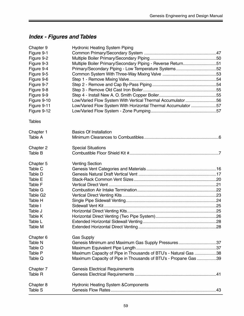
Genesis Engineering and Design Manual
59
Index - Figures and Tables
Chapter 9 Hydronic Heating System PipingFigure 9-1 Common Primary/Secondary System ...............................................................47Figure 9-2 Multiple Boiler Primary/Secondary Piping..........................................................50Figure 9-3 Multiple Boiler Primary/Secondary Piping - Reverse Return.............................51Figure 9-4 Primary/Secondary Piping - Low Temperature Systems...................................52Figure 9-5 Common System With Three-Way Mixing Valve ...............................................53Figure 9-6 Step 1 - Remove Mixing Valve............................................................................54Figure 9-7 Step 2 - Remove and Cap By-Pass Piping ........................................................54Figure 9-8 Step 3 - Remove Old Cast Iron Boiler................................................................55Figure 9-9 Step 4 - Install New A. O. Smith Copper Boiler..................................................55Figure 9-10 Low/Varied Flow System With Vertical Thermal Accumulator ...........................56Figure 9-11 Low/Varied Flow System With Horizontal Thermal Accumulator ......................57Figure 9-12 Low/Varied Flow System - Zone Pumping .........................................................57
Tables
Chapter 1 Basics Of InstallationTable A Minimum Clearances to Combustibles .................................................................6
Chapter 2 Special SituationsTable B Combustible Floor Shield Kit #..............................................................................7
Chapter 5 Venting SectionTable C Genesis Vent Categories and Materials .............................................................16Table D Genesis Natural Draft Vertical Vent ....................................................................17Table E Stack-Rack Common Vent Sizes........................................................................20Table F Vertical Direct Vent ..............................................................................................21Table G Combustion Air Intake Termination.....................................................................22Table G2 Vertical Direct Venting Kits ..................................................................................23Table H Single Pipe Sidewall Venting...............................................................................24Table I Sidewall Vent Kit ..................................................................................................25Table J Horizontal Direct Venting Kits..............................................................................25Table K Horizontal Direct Venting (Two Pipe System).....................................................26Table L Extended Horizontal Sidewall Venting ................................................................28Table M Extended Horizontal Direct Venting ....................................................................28
Chapter 6 Gas SupplyTable N Genesis Minimum and Maximum Gas Supply Pressures.................................37Table O Maximum Equivalent Pipe Length ......................................................................37Table P Maximum Capacity of Pipe in Thousands of BTU’s - Natural Gas ...................38Table Q Maximum Capacity of Pipe in Thousands of BTU’s - Propane Gas .................39
Chapter 7 Genesis Electrical RequirementsTable R Genesis Electrical Requirements .......................................................................41
Chapter 8 Hydronic Heating System &ComponentsTable S Genesis Flow Rates............................................................................................43

60
Notes:

A. O. Smith reserves the right to make product changes or improvements at any time without notice.
Part No. AHGMA00106 © 2006 A. O. Smith Water Heaters Printed in U.S.A.
A. O. SMITH WATER HEATERS500 Tennessee Waltz Parkway
Ashland City, TN 37015www.hotwater.com