General information - Elpress UK Distributor / E-Tech ... · Certificate FM20987 12:1 ISO 9001:2000...
10
General information 12:1 Certificate FM20987 ISO 9001:2000 12 Some importants points regarding crimping 2 Standards for crimped connections 3 Instructions for operation and safety 4 Service and maintenance 6 Inspection/certification agreement regarding crimp tools 7 Technical information 8 Development - Technical services 9 General points when using Elpress terminals and connectors at high voltages 10
Transcript of General information - Elpress UK Distributor / E-Tech ... · Certificate FM20987 12:1 ISO 9001:2000...

General information
12:1Certificate FM20987ISO 9001:2000
12
Some importants points regarding crimping 2
Standards for crimped connections 3
Instructions for operation and safety 4
Service and maintenance 6
Inspection/certification agreement regarding crimp tools 7
Technical information 8
Development - Technical services 9
General points when using Elpress terminals andconnectors at high voltages 10

General information
12:2 Certificate FM20987ISO 9001:2000
12
Some importants points regarding crimping
The technique of crimping a terminal on to an electrical conductor has been used over 60 years and is the dominant con-necting technique for power and signal transmission cables.
The most important reasons for the suc-cess of this system are simplicity and safety. Crimping is the optimum tech-nique to provide both.
The system contains, from the smallest to the largest cross section, a previously tested combination of terminal size and tool geometry related to the actual cross section of the conductor.Different manufacturers choose to apply this combination in different ways. For example, a terminal with little material in the barrel can be crimped with a crimp die designed for this geometry. The same ter-minal crimped with another die from a different system, where the die is de-signed for a terminal with a larger barrel, would result in lower crimp reduction which could cause overheating due to poor electrical contact.
Therefore always check that the tools and terminals are tested together. This nor-mally means choosing tools and termi-nals from the same manufacturer, and the same system.
Another factor is variations in the con-struction and material of the conductor. Most, but not all, power conductors which have a given size in mm² are de-signed to comply with IEC 60228 which is an international standard that gives the max conductor resistance per km for
each cross section. The possible geomet-ric variations within this standard can be rather large and may influence the final crimp result.Elpress has considerable experience re-garding these variations and of what spe-cial actions that must be taken to achieve the best crimp quality. Contact us if a spe-cial conductor is to be used.
Different conductor materials are often crimped with completely different die ge-ometries. For copper the most common is the hexagonal crimp. This shape gives a gentle and mechanically strong crimp with little risk of conductor strands being damaged. When crimping aluminium, it is important to break the layers of insulat-ing oxide as efficiently as possible and the indent crimp is the most effective method. On copper connections, by using simple analysis and tests, it is possible to estab-lish if good results may be obtained on a previously un-tested non standard con-ductor size. These tests are based on com-parison with a large number of existing test combinations. Elpress are happy to perform and discuss these tests together with the user.
The most important "system component" is the operator. This person must be pro-vided with the necessary information to enable him to make a proper crimp. A product marking system, clear instruc-tions, easy to use accessories and a com-prehensive training manual must be available from your system supplier. Contact Elpress to receive such material.
Hexagonal crimping.
Indent crimping.

General information
12:3Certificate FM20987ISO 9001:2000
12
Standards for crimped connections
There are many different standards with-in the electrical industry. IEC - the Interna-tional Electrotechnical Commission - issues international standards which, al-though not always compulsory, do have strong influence and are used as a basis within the international terminal trade. In Europe, standards are issued by Cenelec and they directly replace the various na-tional standards which may have existed previously. For crimp connections a Cenelec standard was issued during 2003. In many countries national standards have been in force over a long time. In UK the electrical standards are issued by BSI - the British Standards Institution - and are called BS standards. In Germany there are the well known DIN and VDE standards. In Sweden they are called SEN standards and in France NF, etc. Even if the new Cenelec standard has been issued, these old standards will still be referred to over many years.
The application of different standards also varies. In some cases a standard must be followed according to instructions from an authority concerned. In some cas-es there is an agreement between buyer and seller to follow a special standard, while in other instances the user may have an expectation that a relevant standard is complied with.
Within crimping there are many stand-ards all over the world and many of them have an established position in their home market. Due to the high costs of testing to all these standards, most prod-ucts are tested only to the standard of the country of origin and it is therefore impor-tant to know what that standard con-tains.
Prior to August 1993, there were no inter-national testing norms for terminals de-signed for cable sizesabove 10 mm². Then IEC 61238:1 was issued which states how both crimped and screwed terminals and connectors on power cables should be tested. Because it is relatively new, it will take several years before there is exten-sive testing carried out according to the requirements of this standard and its up-date from 2003. Until then one has to rely on the national standards against which there is also considerable practical experi-ence which verifies their validity.
The following testing standards are some examples of old standards now to be replaced by EN 61238-1 (IEC 61238-1:2003):
In addition to these performance stand-ards, which typically involve testing by pull-out, temperature cycling and short-circuiting, there are standards based on dimension of the products which mainly apply in Germany and France.
Within the cross section area range below 10 mm², there are a great number of standards based on dimension, especially within DIN. Testing standards exist for some terminal types, for example DIN 46249 for roll crimped receptacles or SEN 245010 for tube and sheet-metal termi-nals from 0,75 mm².Especially within the pre-insulated termi-nal group, American norms from the Un-derwriters Laboratiories, UL, are sometimes applied such as UL 310, UL 486.
It is in many cases acceptable for a suppli-er and a user to state what standard a ter-minal should completely or partly comply with. Elpress normally comply with Swed-ish, German and UK standards depending on what market the product is designed for and Elpress has therefore had vast ex-perience when it comes to choice of standard. Contact us for further informa-tion.Country
Copperterminals
Aluminiumterminals
SE SEN 245010 SEN 245012
FI SFS 2663 T2
DE VDE 0220:1 VDE 0220:2
GB BS 4579:1 BS 4579:3
FR NF C20-130 NF C63-061/A

General information
12:4 Certificate FM20987ISO 9001:2000
12
Instructions for operation and safety
The method of crimping requires very high forces. Elpress hydraulic and me-chanical tools provide these in the safest way. Without proper instructions being available and carefully followed, full safe-ty can however not be achieved. Every El-press tool is accompanied by detailed instructions of how to use the tool. Read these instructions very carefully prior to use.
Correct use of the tools:increases productivity
increases life expectancy
ensures the quality of the operations
minimizes the risk for accidents
Here are some simple and common rules which Elpress recommend all users to ap-ply:
- Before crimping, a careful visual inspec-tion of the tool should be performed. Pump, crimp tool, presshead, forks, con-nections, hoses and other accessories are checked to ensure that they are clean and without defects. Check that the accesso-ries are correctly inserted into the tool be-fore use.
- All operators must wear safety equip-ment such as protective goggles, gloves and safety shoes. This is a general precau-tion against working injuries and is nor-mally a requirement according to the local industrial safety rules.
- The pressure in the hydraulic pumps must be checked regularly.
- Hydraulic pressure should not be applied in a hose which is sharply bent. The hose is specially made for high operational pressure and cannot be replaced by any other type.
- The tools must be calibrated at usage re-lated intervals (at least yearly), for exam-ple with a gauge. Contact Elpress for more information.
- Check that the right tool and die-set combination have been chosen for the terminal or conductor which is to be crimped.
- Hydraulic tools must never be carried by the hose or coupling.
- Be careful, do not drop heavy objects on the hydraulic hose. It can damage the re-inforcement and cause leakage. If a leak-age occurs, oil at high pressure can pierce the skin with resulting internal injuries. In
such cases always seek medical advice at once.
- Check that the work object is electrically switched off before the crimping starts. The tools are not designed for use on live circuits.
- Remember that all crimping tools deliver high forces. Do not stand in front of a tool in the direction of the pressforce.
- Be aware of the risk of pinch and cut in-juries when operating. This includes all types of crimp tools and cable cutters.
- If there is a suspected defect on a crimp-ing system, always contact Elpress au-thorized service department. Do not use the part in question until serviced.
Checking crimp results
Ensure that a tool has performed the correct crimp and the desired deforma-tion is achieved. This deformation pro-vides mechanical resistance as well as excellent electric characteristics.
The following is considered for copper ter-minals and connectors:
Inspect the measure "N" on the hexag-onal faces where the impressions of the crimp dies are made. See measur-ing points on following page.
Measure with a sliding caliper on either side of the impression and compare with the "N"-dimension in the table. In the cases where the impression is missing, the "N"-dimension is meas-ured in the direction of the crimp force. Note that the hexagon is often not symmetric.
If the result of measuring exceeds the "N"-dimension (according to the table on the next page) after a correctly per-formed crimp, contact Elpress author-ized service department.
KRF/KSF types
Cu conductormm²
Crimpdies No.
max N mm
10 8 6,3
16 9 7,3
25 11 8,8
35 13 10,2
50 14,5 11,4
70 17 13,4
95 20 16,4 (B-dies)
95 20 15,8 (TB-dies)
120 22 16,3
150 25 20,3
185 27 20,5
240 30 23,3
300 32 24,5
400 36 27,3
400 38 30,3
Type KRF/KSF with DUAL-dies
Cu conductormm²
Dual-dies No.
max Nmm
16 DB/DCB 9 7,5
25 DB/DCB11 8,9
35 DB/DCB13 10,6
50 DB/DCB14,5 11,6
70 DB/DCB17 13,6
95 DB/DCB20 15,9
120 DB/DCB22 17,6
150 DB/DCB25 20,1
185 DB/DCB27 21,6
240 DB/DCB30 23,9
300 DB/DCB32 25,6
KRD/KSD types
Cu conductormm²
Crimpdies No.
max N mm
10 - -
16 8 6,3
25 9 7,3
35 11 8,8
50 12 10,2
70 14 11,6
95 16 13,2
120 19 15,4 (B-dies)
120 19 15,2 (TB-dies)
150 22 16,3
185 25 20,3
240 27 20,5
300 30 23,3
400 32 24,5
General information
12:5Certificate FM20987ISO 9001:2000
12
For Cu branch connectors, the "h"-dimen-sion must be measured. This is made on the maximum height of the crimped oval, preferably with a sliding caliper. The di-mensions are compared with the table below.
If the result of measuring exceeds the "h"-value after a correctly performed crimp, contact Elpress authorized service depart-ment.
See measuring points on above picture.
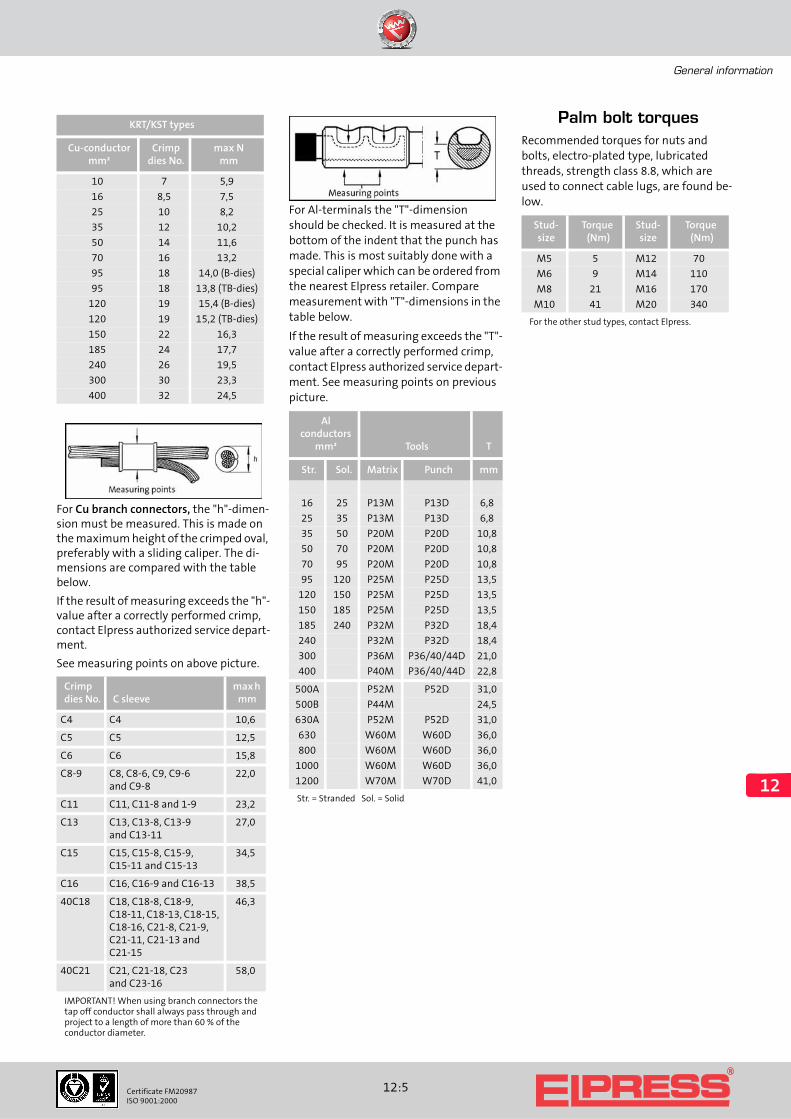
For Al-terminals the "T"-dimension should be checked. It is measured at the bottom of the indent that the punch has made. This is most suitably done with a special caliper which can be ordered from the nearest Elpress retailer. Compare measurement with "T"-dimensions in the table below.
If the result of measuring exceeds the "T"-value after a correctly performed crimp, contact Elpress authorized service depart-ment. See measuring points on previous picture.
Palm bolt torquesRecommended torques for nuts and bolts, electro-plated type, lubricated threads, strength class 8.8, which are used to connect cable lugs, are found be-low.
KRT/KST types
Cu-conductormm²
Crimpdies No.
max N mm
10 7 5,9
16 8,5 7,5
25 10 8,2
35 12 10,2
50 14 11,6
70 16 13,2
95 18 14,0 (B-dies)
95 18 13,8 (TB-dies)
120 19 15,4 (B-dies)
120 19 15,2 (TB-dies)
150 22 16,3
185 24 17,7
240 26 19,5
300 30 23,3
400 32 24,5
Crimpdies No. C sleeve
max h mm
C4 C4 10,6
C5 C5 12,5
C6 C6 15,8
C8-9 C8, C8-6, C9, C9-6and C9-8
22,0
C11 C11, C11-8 and 1-9 23,2
C13 C13, C13-8, C13-9and C13-11
27,0
C15 C15, C15-8, C15-9, C15-11 and C15-13
34,5
C16 C16, C16-9 and C16-13 38,5
40C18 C18, C18-8, C18-9, C18-11, C18-13, C18-15, C18-16, C21-8, C21-9, C21-11, C21-13 and C21-15
46,3
40C21 C21, C21-18, C23and C23-16
58,0
IMPORTANT! When using branch connectors the tap off conductor shall always pass through and project to a length of more than 60 % of the conductor diameter.
Al conductors
mm² Tools T
Str. Sol. Matrix Punch mm
16 25 P13M P13D 6,8
25 35 P13M P13D 6,8
35 50 P20M P20D 10,8
50 70 P20M P20D 10,8
70 95 P20M P20D 10,8
95 120 P25M P25D 13,5
120 150 P25M P25D 13,5
150 185 P25M P25D 13,5
185 240 P32M P32D 18,4
240 P32M P32D 18,4
300 P36M P36/40/44D 21,0
400 P40M P36/40/44D 22,8
500A P52M P52D 31,0
500B P44M 24,5
630A P52M P52D 31,0
630 W60M W60D 36,0
800 W60M W60D 36,0
1000 W60M W60D 36,0
1200 W70M W70D 41,0
Str. = Stranded Sol. = Solid
Stud-size
Torque(Nm)
Stud-size
Torque(Nm)
M5 5 M12 70
M6 9 M14 110
M8 21 M16 170
M10 41 M20 340
For the other stud types, contact Elpress.

General information
12:6 Certificate FM20987ISO 9001:2000
12
Service and maintenance
Elpress crimp tools and power units are designed for long life with maintained high personal safety and performance. All types of professional crimp systems de-velop high forces and must therefore be handled with care. Here are some exam-ples of forces developed in Elpress crimp tools:
Mechanical tools 5-60 kN
Hydraulic tools
-V500, V611, PV600 60 kN
-V800 80 kN
-V1300(C)(Ti) 130 kN
V1400 200 kN
V250 250 kN
V1470 400 kN
Note: 10 kN is approx. 1 ton
Regular inspections must be made to en-sure the high safety and performance of Elpress tools. These pieces of advice may serve as a guide to perform these inspec-tions.
When you suspect a malfunction or a fault, always contact Elpress or an Elpress representative.
Inspection of crimp heads and hydraulic hoses
Inspection of hydraulic pumps
Inspection of forks, die holders, crimp dies, punches and matrixes
Inspection of mechanical hand tools
Beforeuse
Regularly(1-3 t/year) Notes
Outerdefects
X
Cracks X
Free fromdirt andother ob-structions
X
Oil leakage X
Protectioncap
X
Connection/quickcoupling
X
Mainte-nance, service
X Done byauth. serviceunits
Beforeuse
Regulary(1-3 t/year) Notes
Outerdefects
X
Cracks X
Free fromdirt andother obstruc-tions
X
Oilleakage
X
1Check of oilpressure
X V1480,P4000, P6000, PS700,P8000
2Check of crimpforce
X V500, V611, V1311
Mainte-nance,service
X Done byauth.serviceunits
1 For measuring this pressure we recommend the pressure gauge 10020 for the pumps P4000 and PS700. The pumps should release at 630 bar, which is the standard pressure setting at delivery.The pressure gauge 10020, ø 100 mm, with a maximum force indication pointer and snap-coupling for Elpress pumps, has an industrial design with house and cap from black enamelled steel. Measuring range is up to 1000 bar.
2 For measuring this force we recommend the power gauge M1300. It can also be used for inspection of the pumps P4000 and PS700, under the assump-tion that they are connected to a V1300-presshead.When using this power gauge the force should release at 130 kN. If the pressure is too low or alternatively too high, or if the pointer "falls" quickly between the pump strokes (only for the pump P4000 and the tool V1311), the pump must be sent to an Elpress authorized service unit.
The pressure gauge M1300, ø 160 mm, has a maximum force indication pointer and a special connection for the V1300-system. It has an industrial design with house and cap from black enamelled steel. Measuring range is up to 200 kN. (M1300 is mainly designed for use at service departments.)
Beforeuse
Regularly(1-3 t/year)
Outer defects X
Cracks X
Free from dirt andother obstructions
X
Quick coupling X
Spring ball locking X
1Inspection of crimp dies
X
1) Contact Elpress for more information.
Beforeuse
Regularly(1-3 t/year)
Outer defects X
Cracks X
Free from dirt andother obstructions
X
Wet oiling of moving parts
X
1Calibration X
1) The tools are calibrated with a gauge. Contact Elpress for more information.

General information
12:7Certificate FM20987ISO 9001:2000
12
Inspection/certification agreement regarding crimp tools
GeneralTo safeguard the tool quality, Elpress can offer our customers maintenance and certification agreements. In such an agreement the inspection intervals, based on use, are established. Thereafter we call in the tools and perform the nec-essary actions to achieve a trouble-free function. These actions are recorded and a certificate is sent back with the tool.
The inspections may also be performed at the customers premises.
Certification scopeThe inspection/certification is done in ac-cordance with Elpress’ current instruc-tions for the tool in question and forms a part of Elpress’ ISO 9001:2000 certifica-tion.After acceptance a certificate is issued.All inspected tools have signed accept-ance labels.Dies are marked with colours and number to indicate last month for next inspec-tion/calibration. Alternative marking to customer specifications can be done.Non-functioning and/or inspectable tools are repaired after customers agreement.
Preventive maintenance may comprise:
General inspection and function tests
Exchange of seals, etc
Check/exchange of oil
Adjustments of force, pressure, etc.
Cleaning
Safety inspection
Final inspection
The maintenance actions may vary due to type of equipment. When setting up a maintenance agreement a detailed plan is specified. Certificate is issued after completed actions.
Spare partsExchange spare parts deemed by our serv-ice staff to be necessary to bring the tool to a functionable state are charged in accordance with current price lists. Before significant repairs are done, the customer is contacted.Note that only authorised service units, with access to technical information, may repair Elpress products.All hydraulic tools works with high pres-sure technology, which requires special knowledge.
TermsExchange equipment may normally be offered if the customer so needs until his equipment is ready to be returned.
Such exchange equipment must be sent back complete with its packing and without delay to Elpress.
Possible damage will be repaired and charged.
General materials used when repairing the tool will not be charged separately.
Maintenance agreements are set up for 12 month periods and our fees are charged in advance. Notice of termina-tion is three months before the end of a period.
More informationFor more information, contact your nearest Elpress representative. Elpress service units is:Sweden, KramforsPhone: +46 612 71 71 80E-mail: [email protected]
Denmark, SilkeborgPhone: +45 8681 6111E-mail: [email protected]
Germany, ViersenPhone: +49 2162 93 190E-mail: [email protected]
Elpress certificate.
Elpress certified tool ESA0760.
Elpress hydraulic handtool, V1311.
B-dies.

General information
12:8 Certificate FM20987ISO 9001:2000
12
Technical information
Materials for connectionsElpress uses copper, brass and aluminium as termination materials. The copper and brass products are in most cases electro-plated with tin to achieve increased pro-tection against corrosion. The copper in a bimetallic (copper-aluminium) terminal is left unplated on the palm. As insulation material for the pre-insulated terminals, polycarbonate is mainly used.
CopperCopper has always been used in electrical connections. Elpress uses copper of at least 99,9 % purity in the terminals. The advantages of such copper are,
high conductivity
high corrosion resistance
good deformation properties
good jointing ability
During manufacturing, the crimp barrel is annealed to achieve a good deformation around the conductor when crimping. This gives a crimped connection with low contact resistance and good mechanical characteristics.
BrassBrass is mainly used for connections in the cross-section area up to 6 mm², where good spring properties are required. Brass is an alloy metal comprising 70 % copper and 30 % zinc with excellent cold forming property.
AluminiumAluminium used for connectors and cable lugs has a purity of at least 99,7 % and its good characteristics are as follows,
low weight
strong, in relation to its weight
good conductivity, around 60 % of that of copper
easy to work
Conductor designBelow please find references to informa-tion from standards in force which might be of interest.
IEC 60228, which gives:
Information about materials, construc-tions and resistance values for both cop-per and aluminium conductors.Class 1: solid conductorsClass 2: stranded conductorsClass 5: flexible conductorsClass 6: high flexible conductors
Cross-reference table for AWG/MCM to corresponding crosssection in mm²
MCMNo
Areamm²
AWGNo
Areamm²
250 127 36 0,013
300 152 34 0,020
350 177 32 0,032
400 203 30 0,051
450 228 28 0,080
500 253 26 0,13
550 279 24 0,20
600 304 22 0,33
650 329 20 0,56
700 355 19 0,65
750 380 18 0,82
800 405 17 1,04
850 431 16 1,31
900 456 15 1,65
1000 507 14 2,08
1100 557 13 2,62
1200 608 12 3,31
1300 659 11 4,17
1400 709 10 5,26
1500 760 9 6,63
1600 811 8 8,37
1700 861 7 10,6
1800 912 6 13,3
1900 963 5 16,8
2000 1013 4 21,2
3 26,4
2 33,6
1 42,4
250 127 1/0 53,5
250 127 2/0 67,42/0 67,4
3/0 85,0
250 127 1/0 53,54/0 107
Notes1. The information in this table is derived from catalogues distributed by cable suppliers and does not relate to official standards.2. The cross sections that relate to AWG vary depending on different designs of the conductors, ie number of strands.AWG > 20 relates to solid conductors.AWG ≤ 20 relates to multi-strand conductors.The exact cross sections for specific number of strands can be found in cable-supplier catalogues.

General information
12:9Certificate FM20987ISO 9001:2000
12
Development - Technical services
Elpress is one of Europe’s leading manu-facturers of electrical connection crimp-ing systems and has almost 50 years experience of applications, from nuclear power plants to small electrical units.
Exposure to mechanical and thermal loads is especially relevant to electrical connections.Therefore Elpress devotes large resources to achieve commercial and technical suc-cess through an ongoing product devel-opment towards better user economy, quality and performance.
For this purpose Elpress have a modern laboratory with equipment to perform:
High current load tests
Mechanical tensile strength tests
Cyclical thermal load tests
Vibration tests
Corrosion cabinet tests
Resistance measurements etc.
Hydraulic impulse test
The laboratory function also includes the-oretical studies, prototype generation, technical documentation and advice.
The skill of the staff together with good laboratory and computer equipment form strong competitive advantages both when it comes to consulting services and developing projects.
Testing of connections at the Elpress laboratory.

General information
12:10 Certificate FM20987ISO 9001:2000
12
General points when using Elpress terminals and connectors at high voltages
TerminationsThe modern and easy to use termination kits for 12 to 36 kV XLPE-insulated cable, which consist of prefabricated modules or even complete terminations, give no or very few restrictions in using terminal lugs of AK, AKK or KRF types.Included are also the so called ”pins” of type designation AKP.
An important consideration when termi-nating an outdoor copper cable with a copper terminal: The KRF type has an in-spection hole which after assembly pref-erably should be made watertight. Your supplier of termination kits can give you his specific solution.
When using terminals of AK, AKK or AKP types at high voltages, there are today complete solutions for end terminations up to 84 kV both of heat shrink and push-on types.When in doubt, always consult your sup-plier of end terminations for his specific solution in matters related to technical details upon performance.
When performing an end termination for oil impregnated paper cable where an oil tank is used, most often the supplier has his specially designed solution.
Elpress terminal lugs of AK and AKK are used with a so called ”dry” end termina-tion.
Connections
XLPE to XLPE
Today there are commonly four types of connections used within voltage area 12 to 36 kV. These are: tape, heat shrink, cold shrink, and pre-fabricated (push on) con-nections. Most of these connections can use Elpress through connectors of the AS, AKS and KSF/KSD/KST types.Special connectors with cone shaped ends are normally not required today within these voltages.
Different connection kit suppliers recom-mend different techniques to deal with indent cavities, space between cable insu-lation and connector and etc.
It is important to follow the supplier in-structions when carrying out these as-semblies. If you are uncertain, or if the assembly instructions do not give you an-swers to your questions, consult your sup-plier.
At higher voltages, for example 52 and 84 kV, there are other requirements on the connectors depending on the connection design. There are, however, solutions where ”normal” connectors are used to-gether with additional materials in the voltage range up to 145 kV.
Through connectors for XLPE paper insulation
When making a connection between ca-bles with oil impregnated paper insula-tion and XLPE insulation at 12 kV and above, through connectors with partition should be used, irrespective of connecting method or manufacture. The through connectors of AS, AKS and KSFM types al-ways have this partition.
Through connectors for paper insula-tion to paper insulation
When connecting two cables with oil im-pregnated paper insulations against each other, through connectors of AS, AKS and KSF/KSD/KST types can be used both in case of an oil tube connection or a heat shrink connection.