GCODE Commands
24
56 Summary Of GCODE Commands By Category SET UP COMMANDS CODE COMMAND FORMAT PURPOSE PAGE # F Feed Speed Fn Designates feed rate, or rate 23 of movement, of the axes. G4 Dwell Time G4/d Specifies a programmed delay 27 during a drill cycle. G90 Absolute Coordinates G90 Indicates that absolute 34 coordinates will be used to perform subsequent motion commands. G91 Incremental Coordinates G91 Indicates that incremental 35 coordinates will be used to perform subsequent motion commands. G92 Set Absolute Position G92XxYyZzAa Sets new absolute 35 coordinates for the current position. M0 Program Pause M0 Pauses the .NC file run. 37 M30 End Of Data M30 Designates the end of a block 40 of commands in a file. M3 Spindle On M3 or Starts the spindle. 37 M4 M4 M5 Spindle Off M5 Turns the spindle off. 38 M6 Tool Change M6T# Allows the tool to be changed 39 by turning off the spindle and coolant and pausing the program. M7 Coolant On M7 or Turns the coolant on. 39 M8 M8 M9 Coolant Off M9 Turns the coolant off. 40 M57 Digital I/O CNTRL M57 Turns Output ON/OFF, 41 Checks for Inputs M90 Output Off M90 OUT# Turns off the designated 42 output. M91 Output On M91 OUT# Turns on the designated 42 output.
-
Upload
laughingly-urs-bianong -
Category
Documents
-
view
156 -
download
2
description
Gcodes commands for CNC Training
Transcript of GCODE Commands
56
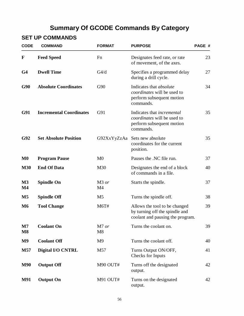
Summary Of GCODE Commands By Category
SET UP COMMANDS
CODE COMMAND FORMAT PURPOSE PAGE #
F Feed Speed Fn Designates feed rate, or rate 23 of movement, of the axes.
G4 Dwell Time G4/d Specifies a programmed delay 27 during a drill cycle.
G90 Absolute Coordinates G90 Indicates that absolute 34 coordinates will be used to perform subsequent motion commands.
G91 Incremental Coordinates G91 Indicates that incremental 35 coordinates will be used to perform subsequent motion commands.
G92 Set Absolute Position G92XxYyZzAa Sets new absolute 35 coordinates for the current position.
M0 Program Pause M0 Pauses the .NC file run. 37
M30 End Of Data M30 Designates the end of a block 40 of commands in a file.
M3 Spindle On M3 or Starts the spindle. 37 M4 M4
M5 Spindle Off M5 Turns the spindle off. 38
M6 Tool Change M6T# Allows the tool to be changed 39 by turning off the spindle and coolant and pausing the program.
M7 Coolant On M7 or Turns the coolant on. 39 M8 M8
M9 Coolant Off M9 Turns the coolant off. 40
M57 Digital I/O CNTRL M57 Turns Output ON/OFF, 41 Checks for Inputs
M90 Output Off M90 OUT# Turns off the designated 42 output.
M91 Output On M91 OUT# Turns on the designated 42 output.
57
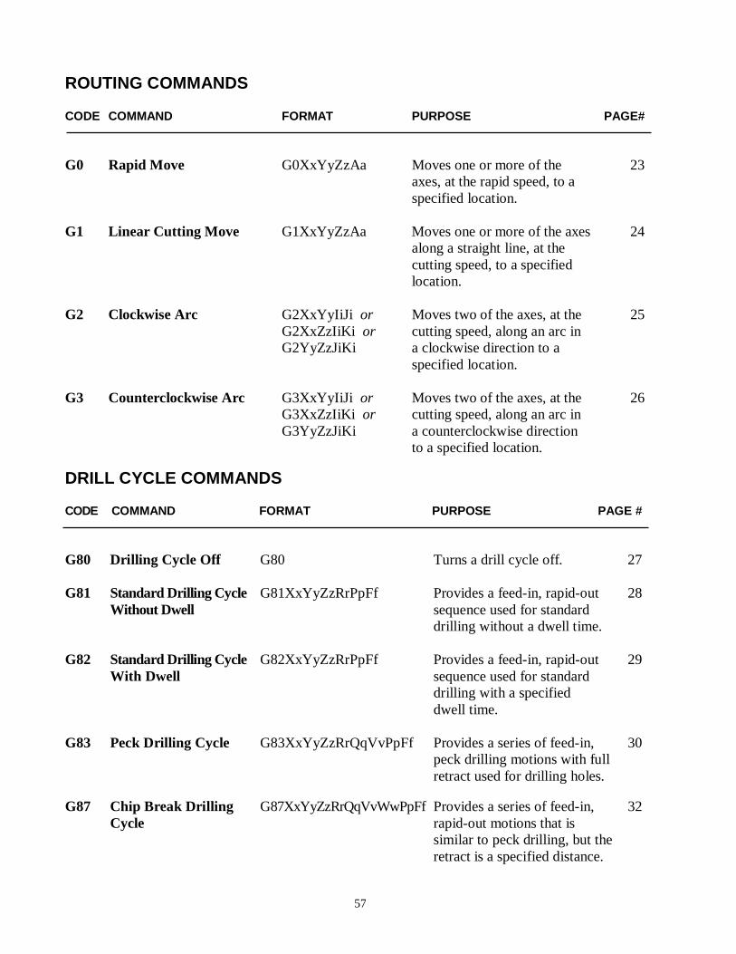
ROUTING COMMANDS CODE COMMAND FORMAT PURPOSE PAGE# G0 Rapid Move G0XxYyZzAa Moves one or more of the 23
axes, at the rapid speed, to a specified location.
G1 Linear Cutting Move G1XxYyZzAa Moves one or more of the axes 24
along a straight line, at the cutting speed, to a specified location.
G2 Clockwise Arc G2XxYyIiJi or Moves two of the axes, at the 25 G2XxZzIiKi or cutting speed, along an arc in
G2YyZzJiKi a clockwise direction to a specified location.
G3 Counterclockwise Arc G3XxYyIiJi or Moves two of the axes, at the 26 G3XxZzIiKi or cutting speed, along an arc in G3YyZzJiKi a counterclockwise direction
to a specified location.
DRILL CYCLE COMMANDS CODE COMMAND FORMAT PURPOSE PAGE # G80 Drilling Cycle Off G80 Turns a drill cycle off. 27 G81 Standard Drilling Cycle G81XxYyZzRrPpFf Provides a feed-in, rapid-out 28
Without Dwell sequence used for standard drilling without a dwell time.
G82 Standard Drilling Cycle G82XxYyZzRrPpFf Provides a feed-in, rapid-out 29
With Dwell sequence used for standard drilling with a specified dwell time.
G83 Peck Drilling Cycle G83XxYyZzRrQqVvPpFf Provides a series of feed-in, 30
peck drilling motions with full retract used for drilling holes.
G87 Chip Break Drilling G87XxYyZzRrQqVvWwPpFf Provides a series of feed-in, 32 Cycle rapid-out motions that is
similar to peck drilling, but the retract is a specified distance.
58
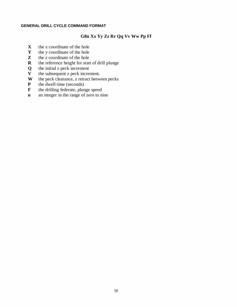
GENERAL DRILL CYCLE COMMAND FORMAT
G8n Xx Yy Zz Rr Qq Vv Ww Pp Ff
X the x coordinate of the hole Y the y coordinate of the hole Z the z coordinate of the hole R the reference height for start of drill plunge Q the initial z peck increment V the subsequent z peck increment. W the peck clearance, z retract between pecks P the dwell time (seconds) F the drilling federate, plunge speed n an integer in the range of zero to nine
59
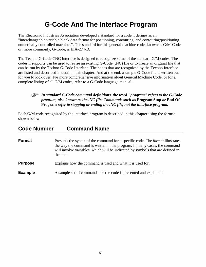
G-Code And The Interface Program The Electronic Industries Association developed a standard for a code it defines as an "interchangeable variable block data format for positioning, contouring, and contouring/positioning numerically controlled machines". The standard for this general machine code, known as G/M-Code or, more commonly, G-Code, is EIA-274-D. The Techno G-Code CNC Interface is designed to recognize some of the standard G/M codes. The codes it supports can be used to revise an existing G-Code (.NC) file or to create an original file that can be run by the Techno G-Code Interface. The codes that are recognized by the Techno Interface are listed and described in detail in this chapter. And at the end, a sample G-Code file is written out for you to look over. For more comprehensive information about General Machine Code, or for a complete listing of all G/M codes, refer to a G-Code language manual.
In standard G-Code command definitions, the word "program" refers to the G-Code program, also known as the .NC file. Commands such as Program Stop or End Of Program refer to stopping or ending the .NC file, not the interface program.
Each G/M code recognized by the interface program is described in this chapter using the format shown below.
Code Number Command Name Format Presents the syntax of the command for a specific code. The format illustrates
the way the command is written in the program. In many cases, the command will involve variables, which will be indicated by symbols that are defined in the text.
Purpose Explains how the command is used and what it is used for. Example A sample set of commands for the code is presented and explained.
60
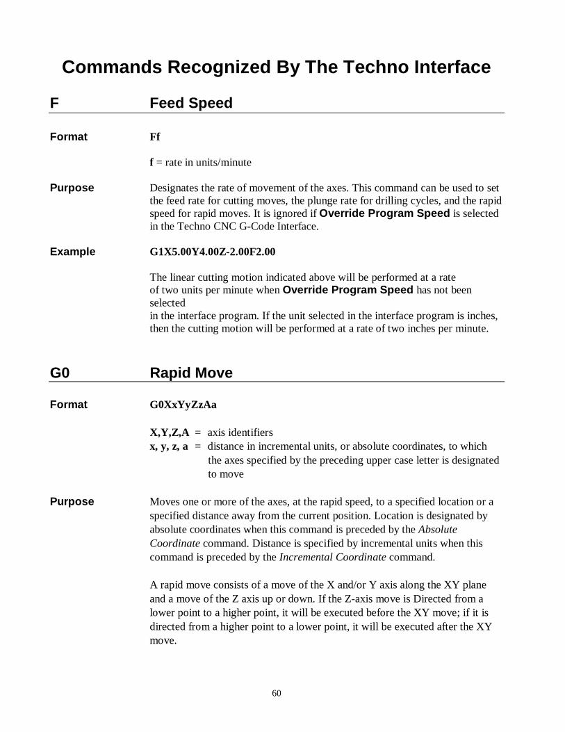
Commands Recognized By The Techno Interface F Feed Speed Format Ff f = rate in units/minute Purpose Designates the rate of movement of the axes. This command can be used to set
the feed rate for cutting moves, the plunge rate for drilling cycles, and the rapid speed for rapid moves. It is ignored if Override Program Speed is selected in the Techno CNC G-Code Interface.
Example G1X5.00Y4.00Z-2.00F2.00
The linear cutting motion indicated above will be performed at a rate of two units per minute when Override Program Speed has not been selected in the interface program. If the unit selected in the interface program is inches, then the cutting motion will be performed at a rate of two inches per minute.
G0 Rapid Move Format G0XxYyZzAa X,Y,Z,A = axis identifiers x, y, z, a = distance in incremental units, or absolute coordinates, to which
the axes specified by the preceding upper case letter is designated to move
Purpose Moves one or more of the axes, at the rapid speed, to a specified location or a
specified distance away from the current position. Location is designated by absolute coordinates when this command is preceded by the Absolute Coordinate command. Distance is specified by incremental units when this command is preceded by the Incremental Coordinate command.
A rapid move consists of a move of the X and/or Y axis along the XY plane
and a move of the Z axis up or down. If the Z-axis move is Directed from a lower point to a higher point, it will be executed before the XY move; if it is directed from a higher point to a lower point, it will be executed after the XY move.
61
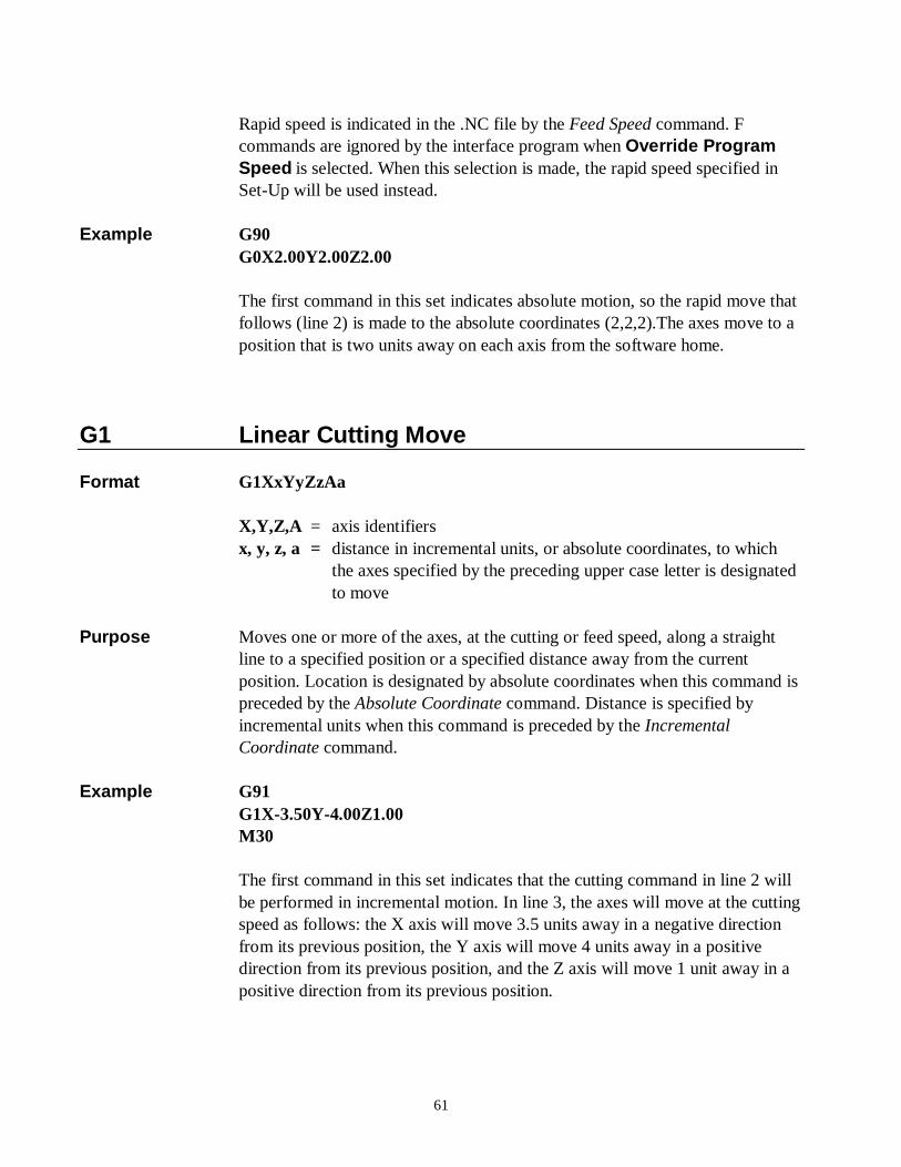
Rapid speed is indicated in the .NC file by the Feed Speed command. F
commands are ignored by the interface program when Override Program Speed is selected. When this selection is made, the rapid speed specified in Set-Up will be used instead.
Example G90 G0X2.00Y2.00Z2.00 The first command in this set indicates absolute motion, so the rapid move that
follows (line 2) is made to the absolute coordinates (2,2,2).The axes move to a position that is two units away on each axis from the software home.
G1 Linear Cutting Move Format G1XxYyZzAa X,Y,Z,A = axis identifiers x, y, z, a = distance in incremental units, or absolute coordinates, to which
the axes specified by the preceding upper case letter is designated to move
Purpose Moves one or more of the axes, at the cutting or feed speed, along a straight
line to a specified position or a specified distance away from the current position. Location is designated by absolute coordinates when this command is preceded by the Absolute Coordinate command. Distance is specified by incremental units when this command is preceded by the Incremental Coordinate command.
Example G91 G1X-3.50Y-4.00Z1.00 M30 The first command in this set indicates that the cutting command in line 2 will
be performed in incremental motion. In line 3, the axes will move at the cutting speed as follows: the X axis will move 3.5 units away in a negative direction from its previous position, the Y axis will move 4 units away in a positive direction from its previous position, and the Z axis will move 1 unit away in a positive direction from its previous position.
62
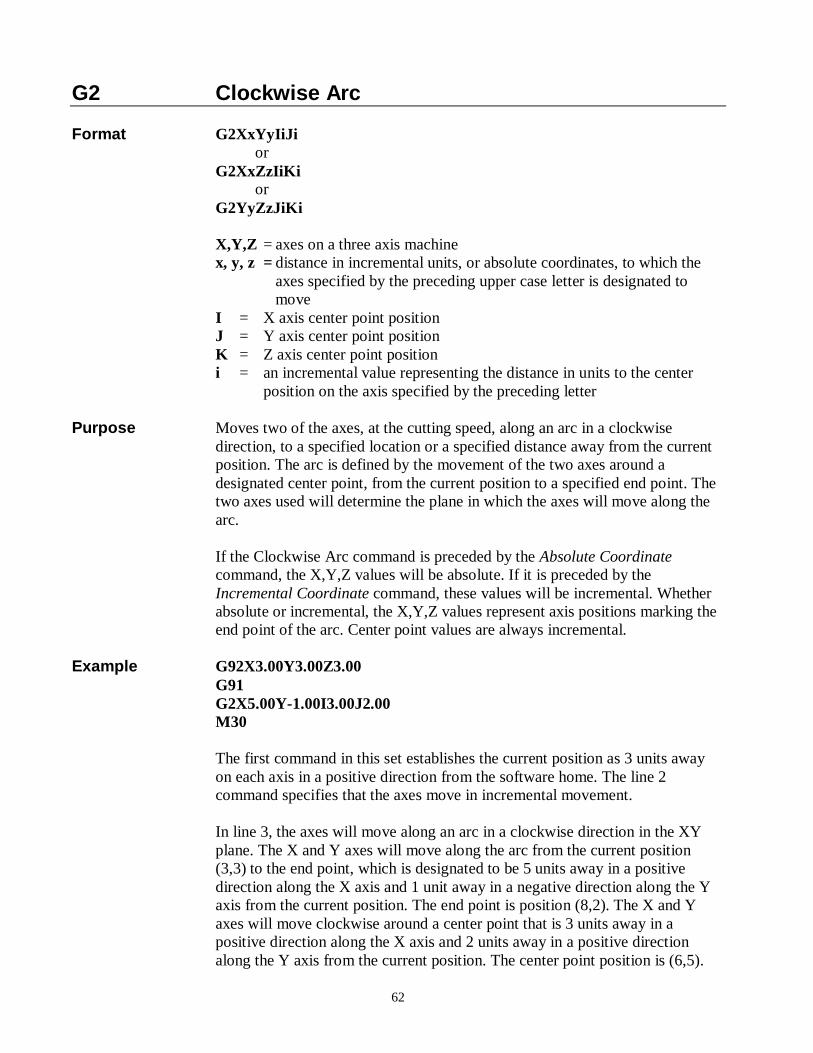
G2 Clockwise Arc Format G2XxYyIiJi or G2XxZzIiKi or G2YyZzJiKi X,Y,Z = axes on a three axis machine x, y, z = distance in incremental units, or absolute coordinates, to which the
axes specified by the preceding upper case letter is designated to move
I = X axis center point position J = Y axis center point position K = Z axis center point position i = an incremental value representing the distance in units to the center
position on the axis specified by the preceding letter Purpose Moves two of the axes, at the cutting speed, along an arc in a clockwise
direction, to a specified location or a specified distance away from the current position. The arc is defined by the movement of the two axes around a designated center point, from the current position to a specified end point. The two axes used will determine the plane in which the axes will move along the arc.
If the Clockwise Arc command is preceded by the Absolute Coordinate
command, the X,Y,Z values will be absolute. If it is preceded by the Incremental Coordinate command, these values will be incremental. Whether absolute or incremental, the X,Y,Z values represent axis positions marking the end point of the arc. Center point values are always incremental.
Example G92X3.00Y3.00Z3.00 G91 G2X5.00Y-1.00I3.00J2.00 M30 The first command in this set establishes the current position as 3 units away
on each axis in a positive direction from the software home. The line 2 command specifies that the axes move in incremental movement.
In line 3, the axes will move along an arc in a clockwise direction in the XY
plane. The X and Y axes will move along the arc from the current position (3,3) to the end point, which is designated to be 5 units away in a positive direction along the X axis and 1 unit away in a negative direction along the Y axis from the current position. The end point is position (8,2). The X and Y axes will move clockwise around a center point that is 3 units away in a positive direction along the X axis and 2 units away in a positive direction along the Y axis from the current position. The center point position is (6,5).
63
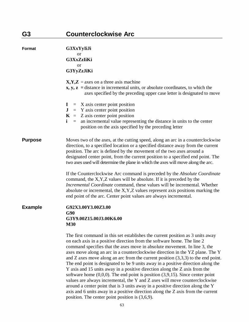
G3 Counterclockwise Arc Format G3XxYyIiJi or G3XxZzIiKi or G3YyZzJiKi X,Y,Z = axes on a three axis machine x, y, z = distance in incremental units, or absolute coordinates, to which the
axes specified by the preceding upper case letter is designated to move I = X axis center point position J = Y axis center point position K = Z axis center point position i = an incremental value representing the distance in units to the center
position on the axis specified by the preceding letter
Purpose Moves two of the axes, at the cutting speed, along an arc in a counterclockwise direction, to a specified location or a specified distance away from the current position. The arc is defined by the movement of the two axes around a designated center point, from the current position to a specified end point. The two axes used will determine the plane in which the axes will move along the arc.
If the Counterclockwise Arc command is preceded by the Absolute Coordinate
command, the X,Y,Z values will be absolute. If it is preceded by the Incremental Coordinate command, these values will be incremental. Whether absolute or incremental, the X,Y,Z values represent axis positions marking the end point of the arc. Center point values are always incremental.
Example G92X3.00Y3.00Z3.00 G90 G3Y9.00Z15.00J3.00K6.00 M30 The first command in this set establishes the current position as 3 units away
on each axis in a positive direction from the software home. The line 2 command specifies that the axes move in absolute movement. In line 3, the axes move along an arc in a counterclockwise direction in the YZ plane. The Y and Z axes move along an arc from the current position (3,3,3) to the end point. The end point is designated to be 9 units away in a positive direction along the Y axis and 15 units away in a positive direction along the Z axis from the software home (0,0,0). The end point is position (3,9,15). Since center point values are always incremental, the Y and Z axes will move counterclockwise around a center point that is 3 units away in a positive direction along the Y axis and 6 units away in a positive direction along the Z axis from the current position. The center point position is (3,6,9).
64
G4 Dwell Time Format G4/d or G4 d d = duration of the timed delay in seconds Purpose Specifies a programmed delay, indicated in seconds. Note that a forward slash
( / ) or blank space must follow G4 in this command. Example G0X2Y2Z2 G4/10 G0X8.00 Y6.00 Z5.00 In this example, the two rapid moves will be separated by a 10 second delay.
G80 Drilling Cycle Off Format G80 Purpose Turns off a drill cycle. This command should follow immediately after the last
drilling cycle command. Example G90 G0X0Y0Z0 G81X1.00Y2.00Z-1 X4.00Y5.00 X7.00Y8.00 G80 In the command set above, the first command designates subsequent motion
commands to be in absolute motion. The standard drill commands in lines 3, 4 and 5 create a series of three holes. (Notice that the drill command code is written only once, in line 3, although it applies to lines 4 and 5 as well.) After the third hole is drilled, the drill cycle is cancelled.
65
G81 Standard Drilling Cycle Without Dwell Format G81XxYyZz X,Y,Z = axes on a three axis machine x, y, z = distance in incremental units, or absolute coordinates, to which the
axes specified by the preceding upper case letter is designated to move
Purpose Provides a feed-in, rapid-out sequence used for drilling a series of holes.
Standard drilling involves a single plunge of the tool at the plunge speed, and a single retraction of the tool to the initial Z position at the rapid speed. The initial Z position is the position of the Z axis before the drilling cycle starts.
The speed at which the Z axis descends into the material will either be the feed
rate specified in the .NC file by the Feed Speed command or the plunge speed specified in Set-Up. The interface program will only recognize the Feed Speed command if Override Program Speed is not selected in Set-Up.
In drilling, the command code usually appears on the first line of the cycle
only, although there may be several holes drilled in the cycle. Also, the Z axis value is always unsigned (i.e., there is no positive or negative sign in front of it).
Example G90 G81X4.00Y6.00Z-1 X6.00 X8.00 G80 G0X10.00Y10.00Z0.00 Line 1 indicates that subsequent motion commands will be in absolute motion.
In the standard drilling cycle initiated in line 2, the X axis moves 4 units in a positive direction away from the software home and the Y axis moves 6 units in a positive direction away from the software home. The X and Y axes move at the cutting speed set in the interface program. A hole is drilled at the new location (4,6). To drill the hole, the Z axis moves 1 unit in a negative direction away from its current (initial) position and then retracts to its initial position. The Z axis moves at the plunge speed set in the interface program.
Two other holes of the same depth are drilled, one at the (6,6) position and one
at the (8,6) position. The drill cycle is ended in line 5, and a rapid move is executed in line 6. This command is executed in absolute motion, according to the Absolute Coordinate command in line 1.
66
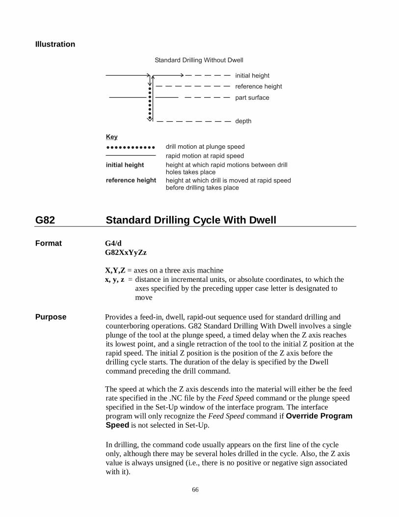
Illustration
Standard Drilling Without Dwell
initial height
reference height
part surface
depth
drill motion at plunge speed
rapid motion at rapid speed
height at which rapid motions between drillholes takes place
height at which drill is moved at rapid speedbefore drilling takes place
Key
������������
initial height
reference height
��������
G82 Standard Drilling Cycle With Dwell Format G4/d G82XxYyZz X,Y,Z = axes on a three axis machine x, y, z = distance in incremental units, or absolute coordinates, to which the
axes specified by the preceding upper case letter is designated to move
Purpose Provides a feed-in, dwell, rapid-out sequence used for standard drilling and
counterboring operations. G82 Standard Drilling With Dwell involves a single plunge of the tool at the plunge speed, a timed delay when the Z axis reaches its lowest point, and a single retraction of the tool to the initial Z position at the rapid speed. The initial Z position is the position of the Z axis before the drilling cycle starts. The duration of the delay is specified by the Dwell command preceding the drill command.
The speed at which the Z axis descends into the material will either be the feed
rate specified in the .NC file by the Feed Speed command or the plunge speed specified in the Set-Up window of the interface program. The interface program will only recognize the Feed Speed command if Override Program Speed is not selected in Set-Up.
In drilling, the command code usually appears on the first line of the cycle
only, although there may be several holes drilled in the cycle. Also, the Z axis value is always unsigned (i.e., there is no positive or negative sign associated with it).
67
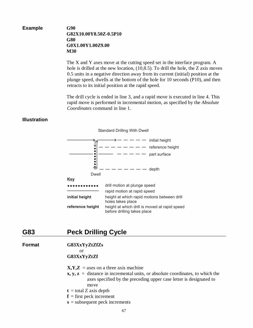
Example G90 G82X10.00Y8.50Z-0.5P10 G80 G0X1.00Y1.00Z9.00 M30 The X and Y axes move at the cutting speed set in the interface program. A
hole is drilled at the new location, (10,8.5). To drill the hole, the Z axis moves 0.5 units in a negative direction away from its current (initial) position at the plunge speed, dwells at the bottom of the hole for 10 seconds (P10), and then retracts to its initial position at the rapid speed.
The drill cycle is ended in line 3, and a rapid move is executed in line 4. This
rapid move is performed in incremental motion, as specified by the Absolute Coordinates command in line 1.
Illustration
Standard Drilling With Dwell
initial height
reference height
part surface
depth
drill motion at plunge speed
rapid motion at rapid speed
height at which rapid motions between drillholes takes place
height at which drill is moved at rapid speedbefore drilling takes place
Key
������������
initial height
reference height
��������
Dwell
G83 Peck Drilling Cycle Format G83XxYyZtZfZs
or G83XxYyZtZf
X,Y,Z = axes on a three axis machine x, y, z = distance in incremental units, or absolute coordinates, to which the axes specified by the preceding upper case letter is designated to move t = total Z axis depth f = first peck increment s = subsequent peck increments
68
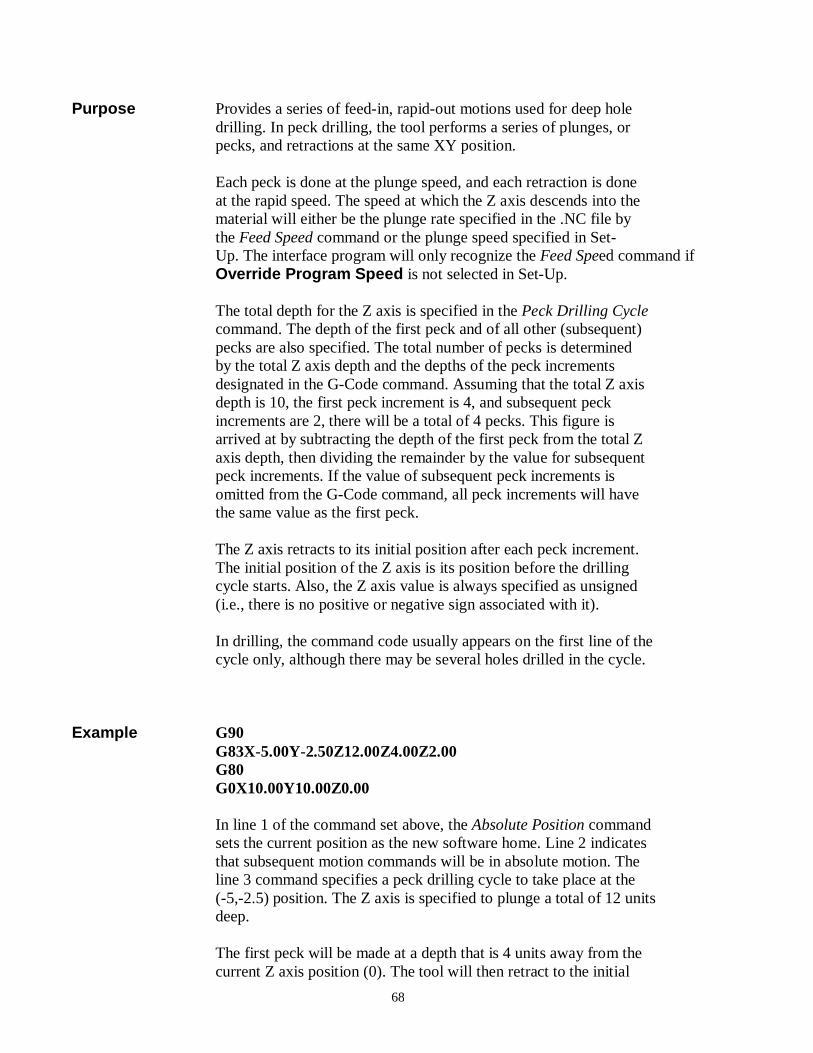
Purpose Provides a series of feed-in, rapid-out motions used for deep hole
drilling. In peck drilling, the tool performs a series of plunges, or pecks, and retractions at the same XY position.
Each peck is done at the plunge speed, and each retraction is done at the rapid speed. The speed at which the Z axis descends into the material will either be the plunge rate specified in the .NC file by the Feed Speed command or the plunge speed specified in Set- Up. The interface program will only recognize the Feed Speed command if Override Program Speed is not selected in Set-Up.
The total depth for the Z axis is specified in the Peck Drilling Cycle command. The depth of the first peck and of all other (subsequent) pecks are also specified. The total number of pecks is determined by the total Z axis depth and the depths of the peck increments designated in the G-Code command. Assuming that the total Z axis depth is 10, the first peck increment is 4, and subsequent peck increments are 2, there will be a total of 4 pecks. This figure is arrived at by subtracting the depth of the first peck from the total Z axis depth, then dividing the remainder by the value for subsequent peck increments. If the value of subsequent peck increments is omitted from the G-Code command, all peck increments will have the same value as the first peck.
The Z axis retracts to its initial position after each peck increment. The initial position of the Z axis is its position before the drilling cycle starts. Also, the Z axis value is always specified as unsigned (i.e., there is no positive or negative sign associated with it). In drilling, the command code usually appears on the first line of the cycle only, although there may be several holes drilled in the cycle.
Example G90
G83X-5.00Y-2.50Z12.00Z4.00Z2.00 G80 G0X10.00Y10.00Z0.00
In line 1 of the command set above, the Absolute Position command sets the current position as the new software home. Line 2 indicates that subsequent motion commands will be in absolute motion. The line 3 command specifies a peck drilling cycle to take place at the (-5,-2.5) position. The Z axis is specified to plunge a total of 12 units deep.
The first peck will be made at a depth that is 4 units away from the current Z axis position (0). The tool will then retract to the initial
69
height, the Z=0 point. There will be four additional pecks, making five pecks in total. The second peck will be made at a position that is 2 units away from the bottom of the first peck. The bottom of the second peck will be -6 units along the Z axis from the initial position, which the tool will retract to after the peck is made. Each of the three remaining pecks in the series will be made at a position that is 2 units away in a negative direction from the bottom of the previous peck. When the tool retracts after each peck, it will return to the initial position, which in this case, is the Z=0 point. The drill cycle is ended in line 4, and a rapid move is performed in line 5. The rapid move is executed in absolute motion, as specified by the Absolute Coordinates command in line 2.
Illustration
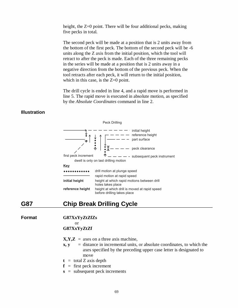
Peck Drilling
initial height
reference height
part surface
subsequent peck instrument
drill motion at plunge speed
rapid motion at rapid speed
height at which rapid motions between drillholes takes place
height at which drill is moved at rapid speedbefore drilling takes place
Key
������������
initial height
reference height
peck clearance
�
� �
�
��
�
�
��
first peck increment
dwell is only on last drilling motion
G87 Chip Break Drilling Cycle Format G87XxYyZtZfZs or G87XxYyZtZf X,Y,Z = axes on a three axis machine, x, y = distance in incremental units, or absolute coordinates, to which the
axes specified by the preceding upper case letter is designated to move
t = total Z axis depth f = first peck increment s = subsequent peck increments
70
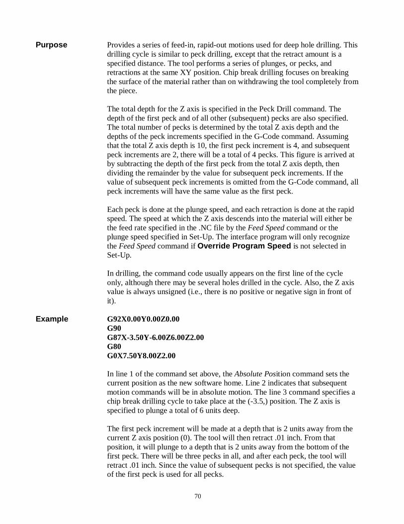
Purpose Provides a series of feed-in, rapid-out motions used for deep hole drilling. This drilling cycle is similar to peck drilling, except that the retract amount is a specified distance. The tool performs a series of plunges, or pecks, and retractions at the same XY position. Chip break drilling focuses on breaking the surface of the material rather than on withdrawing the tool completely from the piece.
The total depth for the Z axis is specified in the Peck Drill command. The
depth of the first peck and of all other (subsequent) pecks are also specified. The total number of pecks is determined by the total Z axis depth and the depths of the peck increments specified in the G-Code command. Assuming that the total Z axis depth is 10, the first peck increment is 4, and subsequent peck increments are 2, there will be a total of 4 pecks. This figure is arrived at by subtracting the depth of the first peck from the total Z axis depth, then dividing the remainder by the value for subsequent peck increments. If the value of subsequent peck increments is omitted from the G-Code command, all peck increments will have the same value as the first peck.
Each peck is done at the plunge speed, and each retraction is done at the rapid
speed. The speed at which the Z axis descends into the material will either be the feed rate specified in the .NC file by the Feed Speed command or the plunge speed specified in Set-Up. The interface program will only recognize the Feed Speed command if Override Program Speed is not selected in Set-Up.
In drilling, the command code usually appears on the first line of the cycle
only, although there may be several holes drilled in the cycle. Also, the Z axis value is always unsigned (i.e., there is no positive or negative sign in front of it).
Example G92X0.00Y0.00Z0.00 G90 G87X-3.50Y-6.00Z6.00Z2.00 G80 G0X7.50Y8.00Z2.00 In line 1 of the command set above, the Absolute Position command sets the
current position as the new software home. Line 2 indicates that subsequent motion commands will be in absolute motion. The line 3 command specifies a chip break drilling cycle to take place at the (-3.5,) position. The Z axis is specified to plunge a total of 6 units deep.
The first peck increment will be made at a depth that is 2 units away from the
current Z axis position (0). The tool will then retract .01 inch. From that position, it will plunge to a depth that is 2 units away from the bottom of the first peck. There will be three pecks in all, and after each peck, the tool will retract .01 inch. Since the value of subsequent pecks is not specified, the value of the first peck is used for all pecks.
71
The drill cycle is ended in line 4, and a rapid move is executed in line 5. The rapid move is performed in absolute motion, as specified by the Absolute Coordinates command in line 2.
Illustration
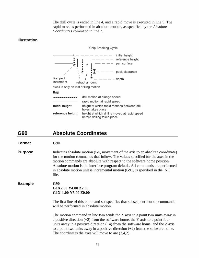
Chip Breaking Cycle
initial height
reference height
part surface
depth
drill motion at plunge speed
rapid motion at rapid speed
height at which rapid motions between drillholes takes place
height at which drill is moved at rapid speedbefore drilling takes place
Key
������������
initial height
reference height
peck clearance
�
� �
�
��
�
�
��
first peckincrement
dwell is only on last drilling motion
�
retract amount
G90 Absolute Coordinates Format G90 Purpose Indicates absolute motion (i.e., movement of the axis to an absolute coordinate)
for the motion commands that follow. The values specified for the axes in the motion commands are absolute with respect to the software home position. Absolute motion is the interface program default. All commands are performed in absolute motion unless incremental motion (G91) is specified in the .NC file.
Example G90 G1X2.00 Y4.00 Z2.00 G1X-1.00 Y5.00 Z0.00 The first line of this command set specifies that subsequent motion commands
will be performed in absolute motion. The motion command in line two sends the X axis to a point two units away in
a positive direction (+2) from the software home, the Y axis to a point four units away in a positive direction (+4) from the software home, and the Z axis to a point two units away in a positive direction (+2) from the software home. The coordinates the axes will move to are (2,4,2).
72
The motion command in line three sends the X axis to the -1 position in relation to the software home (-3 units away from its previous position), the Y axis to the +5 position (+1 unit away from its previous position), and the Z axis to the 0 position (the software home location, -2 units away from its previous position). The coordinates the axes will move to are (-1,5,0).
G91 Incremental Coordinates Format G91 Purpose Indicates incremental motion (i.e., movement of the axis to a position
a specified distance away from its previous position) for the motion commands that follow. Once specified, commands continue to be performed in incremental motion until absolute motion is indicated in the .NC file.
Example G91 G1X2.00 Y4.00 Z2.00 G1X-1.00 Y5.00 Z0.00 The first command specifies that subsequent motion commands will be
performed in incremental motion. The motion command in line two sends the X axis to a point two units away in
a positive direction (+2) from its current position, the Y axis to a point four units away in a positive direction (+4) from its current position, and the Z axis to a point two units away in a positive direction (+2) from its current position. Assuming the current position of the machine is (1,1,1), the machine will then move to position (3,5,3).
The motion command in line three sends the X axis -1 unit away from its
current position of +3, the Y axis +5 units away from its current position of +5, and the Z axis 0 units away from its current position of +3. The machine will move from (3,5,3) to (2,10,3).
G 92 Set Absolute Position Format G92 XxYyZz X,Y,Z = axes whose coordinates are being specified x, y, z = absolute coordinate being assigned to the axis specified by the preceding upper case letter Purpose Sets the new origin, or software home, by changing the absolute position of
one or more axes. New absolute coordinates are assigned to the axes in their current positions, thereby establishing a new software home. Any absolute coordinate specified in a subsequent command is referenced to the new software home position. The current position may be designated as the new software home by assigning the absolute coordinate of 0 to each axis.
73
Example 1 G90 G1X2.00 Y4.00 Z2.00 G92X0Y0Z0 G1X-1.00 Y5.00 Z0.00 The command on the first line indicates that subsequent motion commands will
be performed in absolute motion. In line two, the X axis will be sent to a point 2 units away in a positive
direction from the existing software home, the Y axis will be sent to a point 4 units away in a positive direction from the existing software home, and the Z axis will be sent to a point 2 units away in a positive direction from the existing software home. The coordinates the axes will move to are (2,4,2).
The line three command establishes a new origin, or software home, using
Absolute Position. Each axis is assigned a new absolute coordinate - 0 (zero) - for its current position, changing the coordinates of the current position from (2,4,2) to (0,0,0). The current position has been designated as the new origin, or software home. Subsequent motion commands will be referenced to this new software home.
In line four, the axes make a linear cutting move to absolute coordinates. These
coordinates are relative to the new software home established in line three. The X axis is specified to move to a position -1 unit away from the new origin (1 unit in a negative direction away from its current position), the Y axis is specified to move to a position +5 units away from the new origin (5 units in a positive direction away from its current position), and the Z axis is specified to move to the new origin (which is its current position, so it does not move). The final coordinates of the axes will be (-1,5,0).
Example 2 G90 G1X2.00 Y4.00 Z2.00 G92X4Y3Z6 G1X-1.00 Y5.00 Z0.00 The command on the first line indicates that subsequent motion commands will
be performed in absolute motion. In line two, the axes are sent to the same positions designated by the line two command in Example 1. (See Example 1 for a description of axes movement.) The coordinates the axes will move to are 2,4,2.
The line three command establishes a new origin, or software home, using
Absolute Position. Each axis is assigned a new absolute coordinate for its current position, changing the coordinates of the current position from (2,4,2) to (4,3,6). The current position is referenced to the new origin, or software
74
home, which is 4 units away in a negative direction along the X axis, 3 units away in a negative direction along the Y axis, and 6 units away in a negative direction on the Z axis. Subsequent motion commands will be referenced to this new origin as well.
In line four, the axes make a linear cutting move to absolute coordinates. These
coordinates are relative to the new software home established in line three. The X axis is specified to move to a position -1 unit away from the new origin (5 units away in a negative direction from its current position), the Y axis is specified to move to a position +5 units away from the new origin (2 units away in a positive direction from its current position), and the Z axis is specified to move to the new origin (6 units away in a negative direction from its current position). The final coordinates of the axes will be (-1,5,0).
M0 Program Pause Format M0 Purpose Stops the .NC file from running. The file will continue to run from the point
where it stopped when you click on the Resume button in the interface.. Example G91 G1X4.00Y-2.00Z1.00 M0 G1X5.00Y0.00Z3.00 The first line of this command set specifies that subsequent motion commands
will be performed in incremental motion. Following the first linear cutting command (line 2), the file is stopped using the
Program Stop command. After the Resume button is clicked, the file resumes with another linear cutting move.
M3 or M4 Spindle On Format M3 or M4 Purpose Starts the spindle. After the spindle is turned on, the file is paused for the
amount of time specified next to Spindle Delay in Set-Up.
75
Spindle On commands will only be recognized by the Techno CNC G-Code Interface if Auto is selected in the interface.
Example 1 M3 G90 G1X2.50 Y4.00 Z-2.00 G1X-1.00 Y5.50 Z-1.00 M30 In the command set above, the Spindle On command precedes all motion
commands intended to perform cutting (lines 3 and 4), since the spindle has to be turned on in order for cutting to take place. The End Of Data command, M30, turns the spindle off as it ends the block of commands.
Example 2 M4 G91 G1X8.50Y6.00Z-4.50 G1X12.00Y2.50Z-3.50 M30 The first command in this set turns the spindle on. Cutting moves are then
performed in incremental motion. The End Of Data command turns the spindle off at the end of the command set.
M5 Spindle Off Format M5 Purpose Turns the spindle off. This command will stop the spindle only if Auto has
been selected in the interface. Example M3 G90 G1X2.00 Y4.00 Z-2.00 M5 M0 M3 G1X-1.00 Y5.00 Z-3.00 M30 In the command set above, the spindle is designated to be turned on at the
beginning, in line 1, and then turned off in line 4, following the linear cutting command. The program is stopped in line 5 to allow for adjustments of the machine, tool, or workpiece before the machine is designated to cut again. After the desired adjustments are made, the file will continue to run from the point where it stopped when the Resume button in the interface program's Run
76
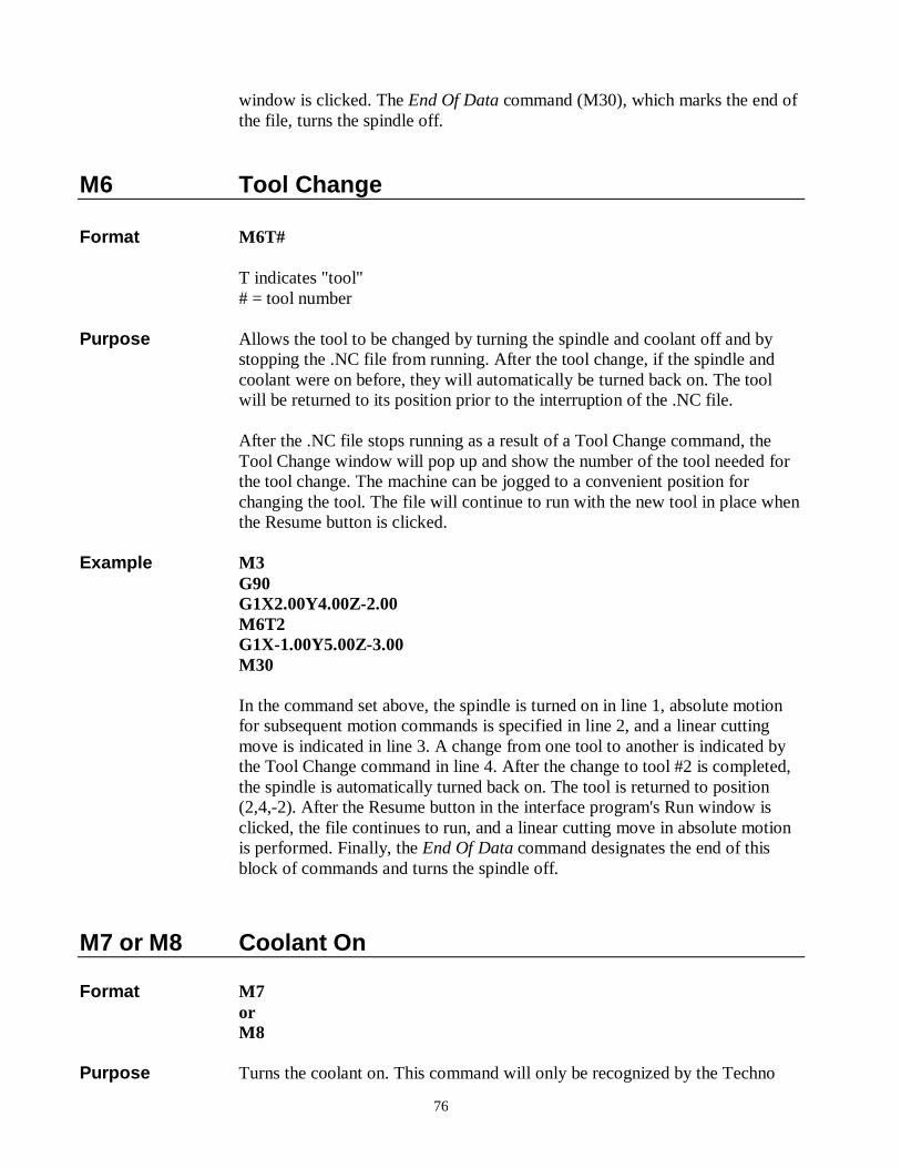
window is clicked. The End Of Data command (M30), which marks the end of the file, turns the spindle off.
M6 Tool Change Format M6T# T indicates "tool" # = tool number Purpose Allows the tool to be changed by turning the spindle and coolant off and by
stopping the .NC file from running. After the tool change, if the spindle and coolant were on before, they will automatically be turned back on. The tool will be returned to its position prior to the interruption of the .NC file.
After the .NC file stops running as a result of a Tool Change command, the
Tool Change window will pop up and show the number of the tool needed for the tool change. The machine can be jogged to a convenient position for changing the tool. The file will continue to run with the new tool in place when the Resume button is clicked.
Example M3 G90 G1X2.00Y4.00Z-2.00 M6T2 G1X-1.00Y5.00Z-3.00 M30 In the command set above, the spindle is turned on in line 1, absolute motion
for subsequent motion commands is specified in line 2, and a linear cutting move is indicated in line 3. A change from one tool to another is indicated by the Tool Change command in line 4. After the change to tool #2 is completed, the spindle is automatically turned back on. The tool is returned to position (2,4,-2). After the Resume button in the interface program's Run window is clicked, the file continues to run, and a linear cutting move in absolute motion is performed. Finally, the End Of Data command designates the end of this block of commands and turns the spindle off.
M7 or M8 Coolant On Format M7 or M8 Purpose Turns the coolant on. This command will only be recognized by the Techno
77
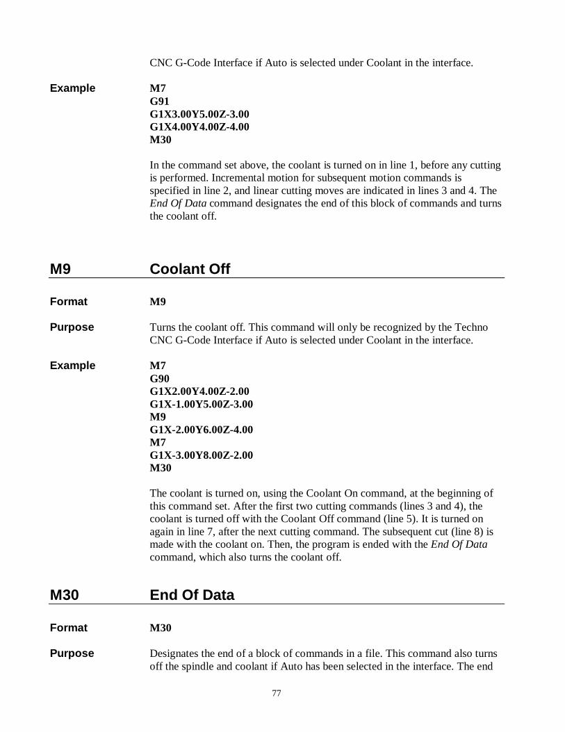
CNC G-Code Interface if Auto is selected under Coolant in the interface. Example M7 G91 G1X3.00Y5.00Z-3.00 G1X4.00Y4.00Z-4.00 M30 In the command set above, the coolant is turned on in line 1, before any cutting
is performed. Incremental motion for subsequent motion commands is specified in line 2, and linear cutting moves are indicated in lines 3 and 4. The End Of Data command designates the end of this block of commands and turns the coolant off.
M9 Coolant Off Format M9 Purpose Turns the coolant off. This command will only be recognized by the Techno
CNC G-Code Interface if Auto is selected under Coolant in the interface. Example M7 G90 G1X2.00Y4.00Z-2.00 G1X-1.00Y5.00Z-3.00 M9 G1X-2.00Y6.00Z-4.00 M7 G1X-3.00Y8.00Z-2.00 M30 The coolant is turned on, using the Coolant On command, at the beginning of
this command set. After the first two cutting commands (lines 3 and 4), the coolant is turned off with the Coolant Off command (line 5). It is turned on again in line 7, after the next cutting command. The subsequent cut (line 8) is made with the coolant on. Then, the program is ended with the End Of Data command, which also turns the coolant off.
M30 End Of Data Format M30 Purpose Designates the end of a block of commands in a file. This command also turns
off the spindle and coolant if Auto has been selected in the interface. The end
78
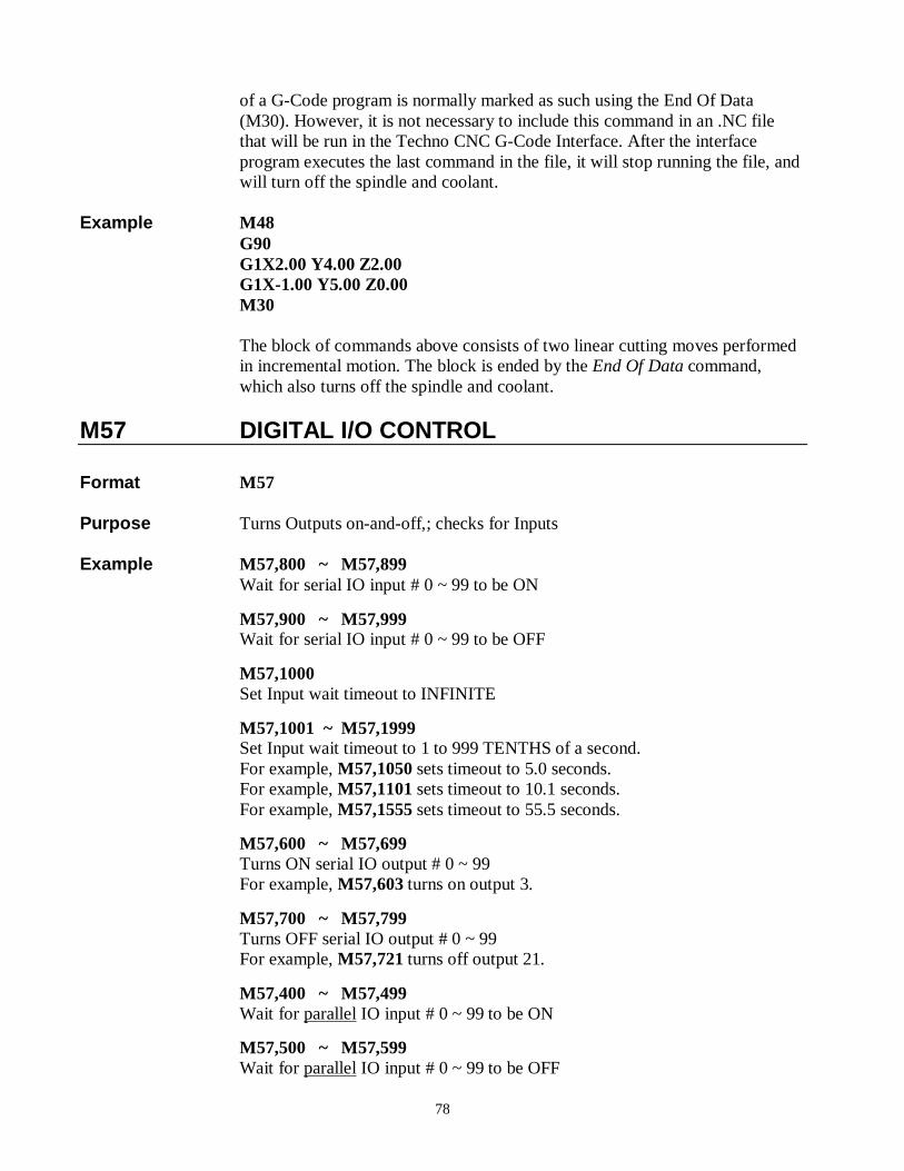
of a G-Code program is normally marked as such using the End Of Data (M30). However, it is not necessary to include this command in an .NC file that will be run in the Techno CNC G-Code Interface. After the interface program executes the last command in the file, it will stop running the file, and will turn off the spindle and coolant.
Example M48 G90 G1X2.00 Y4.00 Z2.00 G1X-1.00 Y5.00 Z0.00 M30 The block of commands above consists of two linear cutting moves performed
in incremental motion. The block is ended by the End Of Data command, which also turns off the spindle and coolant.
M57 DIGITAL I/O CONTROL Format M57 Purpose Turns Outputs on-and-off,; checks for Inputs Example M57,800 ~ M57,899
Wait for serial IO input # 0 ~ 99 to be ON
M57,900 ~ M57,999 Wait for serial IO input # 0 ~ 99 to be OFF
M57,1000 Set Input wait timeout to INFINITE
M57,1001 ~ M57,1999 Set Input wait timeout to 1 to 999 TENTHS of a second. For example, M57,1050 sets timeout to 5.0 seconds. For example, M57,1101 sets timeout to 10.1 seconds. For example, M57,1555 sets timeout to 55.5 seconds.
M57,600 ~ M57,699 Turns ON serial IO output # 0 ~ 99 For example, M57,603 turns on output 3.
M57,700 ~ M57,799 Turns OFF serial IO output # 0 ~ 99 For example, M57,721 turns off output 21.
M57,400 ~ M57,499 Wait for parallel IO input # 0 ~ 99 to be ON
M57,500 ~ M57,599 Wait for parallel IO input # 0 ~ 99 to be OFF
79
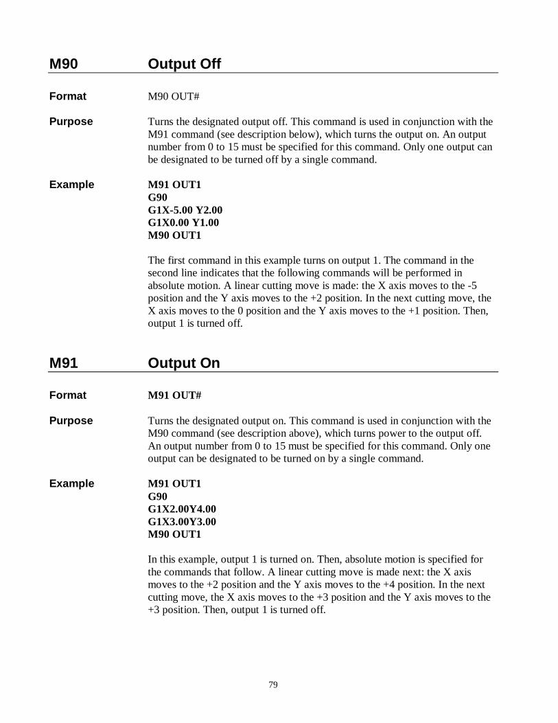
M90 Output Off Format M90 OUT# Purpose Turns the designated output off. This command is used in conjunction with the
M91 command (see description below), which turns the output on. An output number from 0 to 15 must be specified for this command. Only one output can be designated to be turned off by a single command.
Example M91 OUT1 G90 G1X-5.00 Y2.00 G1X0.00 Y1.00 M90 OUT1 The first command in this example turns on output 1. The command in the
second line indicates that the following commands will be performed in absolute motion. A linear cutting move is made: the X axis moves to the -5 position and the Y axis moves to the +2 position. In the next cutting move, the X axis moves to the 0 position and the Y axis moves to the +1 position. Then, output 1 is turned off.
M91 Output On Format M91 OUT# Purpose Turns the designated output on. This command is used in conjunction with the
M90 command (see description above), which turns power to the output off. An output number from 0 to 15 must be specified for this command. Only one output can be designated to be turned on by a single command.
Example M91 OUT1 G90 G1X2.00Y4.00 G1X3.00Y3.00 M90 OUT1 In this example, output 1 is turned on. Then, absolute motion is specified for
the commands that follow. A linear cutting move is made next: the X axis moves to the +2 position and the Y axis moves to the +4 position. In the next cutting move, the X axis moves to the +3 position and the Y axis moves to the +3 position. Then, output 1 is turned off.