GATES, CIRCUITS AND COMPUTING COMPONENTScsl.skku.edu/uploads/ICE2010S15/week3.pdf · 2015-03-19 ·...
70
GATES, CIRCUITS AND COMPUTING COMPONENTS Introduction to Computer Engineering 2015 Spring by Euiseong Seo
Transcript of GATES, CIRCUITS AND COMPUTING COMPONENTScsl.skku.edu/uploads/ICE2010S15/week3.pdf · 2015-03-19 ·...

GATES, CIRCUITS AND COMPUTING COMPONENTS
Introduction to Computer Engineering 2015 Spring by Euiseong Seo

Chapter Goals
¨ Identify the basic gates and describe the behavior of each
¨ Describe how gates are implemented using transistors ¨ Combine basic gates into circuits ¨ Describe the behavior of a gate or circuit using Boolean
expressions, truth tables, and logic diagrams ¨ Compare and contrast a half adder and a full adder ¨ Describe how a multiplexer works ¨ Explain how an S-R latch operates ¨ Describe the characteristics of the four generations of
integrated circuits

Chapter Goals 3
¨ Read an ad for a computer and understand the jargon ¨ List the components and their function
in a von Neumann machine ¨ Describe the fetch-decode-execute cycle of the von
Neumann machine ¨ Describe how computer memory is organized and accessed ¨ Name and describe different auxiliary storage devices ¨ Define three alternative parallel computer configurations ¨ Explain the concept of embedded systems and give
examples from your own home

Computers and Electricity
¨ Gate ¤ A device that performs a basic operation on electrical
signals
¨ Circuits ¤ Gates combined to perform more complicated tasks

Computers and Electricity
¨ How do we describe the behavior of gates and circuits? ¤ Boolean expressions ¤ Uses Boolean algebra, a mathematical notation for
expressing two-valued logic
¨ Logic diagrams ¤ A graphical representation of a circuit ¤ Each gate has its own symbol
¨ Truth tables ¤ A table showing all possible input values and the associated
output values

Gates
¨ Six types of gates ¤ NOT ¤ AND ¤ OR ¤ XOR ¤ NAND ¤ NOR
¨ Typically, logic diagrams are black and white with gates distinguished only by their shape
¨ We use color for emphasis (and fun)

NOT Gate
¨ A NOT gate accepts one input signal (0 or 1) and returns the opposite signal as output
Figure 4.1 Various representations of a NOT gate

AND Gate
¨ An AND gate accepts two input signals ¨ If both are 1, the output is 1;
otherwise, the output is 0
Figure 4.2 Various representations of an AND gate

OR Gate
¨ An OR gate accepts two input signals ¨ If both are 0, the output is 0
otherwise, the output is 1
Figure 4.3 Various representations of an OR gate
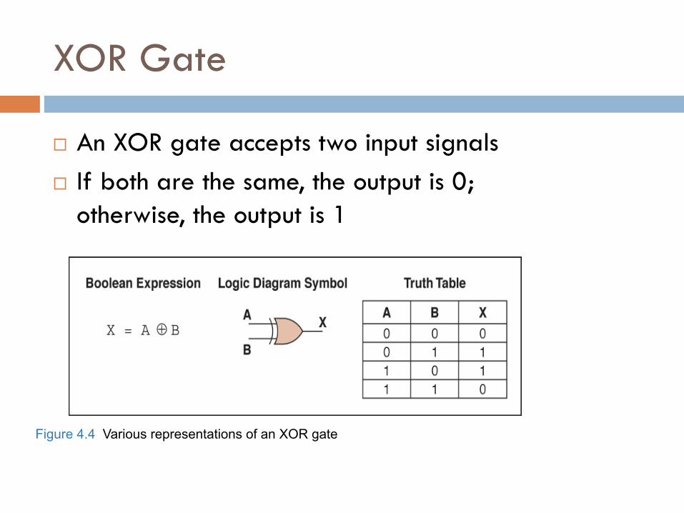
XOR Gate
¨ An XOR gate accepts two input signals ¨ If both are the same, the output is 0;
otherwise, the output is 1
Figure 4.4 Various representations of an XOR gate

XOR Gate
¨ Note the difference between the XOR gate and the OR gate; they differ only in one input situation
¨ When both input signals are 1, the OR gate produces a 1 and the XOR produces a 0
¨ XOR is called the exclusive OR

NAND Gate
¨ The NAND gate accepts two input signals ¨ If both are 1, the output is 0;
otherwise, the output is 1
Figure 4.5 Various representations of a NAND gate
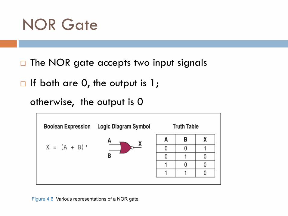
NOR Gate
Figure 4.6 Various representations of a NOR gate
¨ The NOR gate accepts two input signals
¨ If both are 0, the output is 1;
otherwise, the output is 0

Review of Gate Processing
¨ A NOT gate inverts its single input ¨ An AND gate produces 1 if both input values are 1 ¨ An OR gate produces 0 if both input values are 0 ¨ An XOR gate produces 0 if input values are the
same ¨ A NAND gate produces 0 if both inputs are 1 ¨ A NOR gate produces a 1 if both inputs are 0

Gates with More Inputs
¨ Gates can be designed to accept three or more input values
¨ A three-input AND gate, for example, produces an output of 1 only if all input values are 1
Figure 4.7 Various representations of a three-input AND gate

Constructing Gates
¨ Transistor ¤ A device that acts either as a wire that conducts
electricity or as a resistor that blocks the flow of electricity, depending on the voltage level of an input signal
¨ A transistor has no moving parts, yet acts like a switch
¨ It is made of a semiconductor material, which is neither a particularly good conductor of electricity nor a particularly good insulator

17
Constructing Gates
A transistor has three terminals ¤ A source ¤ A base ¤ An emitter, typically connected to
a ground wire
If the electrical signal is grounded, it is allowed to flow through an alternative route to the ground (literally) where it can do no harm
Figure 4.8 The connections of a transistor

Constructing Gates
¨ The easiest gates to create are the NOT, NAND, and NOR gates
Figure 4.9 Constructing gates using transistors

Circuits
¨ Combinational circuit ¤ The input values explicitly determine the output
¨ Sequential circuit ¤ The output is a function of the input values and the
existing state of the circuit
¨ We describe the circuit operations using ¤ Boolean expressions ¤ Logic diagrams ¤ Truth tables

Combinational Circuits
¨ Gates are combined into circuits by using the output of one gate as the input for another

Combinational Circuits
¨ Three inputs require eight rows to describe all possible input combinations
¨ This same circuit using a Boolean expression is (AB + AC)

Combinational Circuits
¨ Consider the following Boolean expression A(B + C)
Does this truth table look familiar?
Compare it with previous table

Combinational Circuits
¨ Circuit equivalence ¤ Two circuits that produce the same output for identical
input ¤ Boolean algebra allows us to apply provable
mathematical principles to help design circuits
¨ A(B + C) = AB + BC (distributive law) so circuits must be equivalent

Properties of Boolean Algebra
Adders
¨ At the digital logic level, addition is performed in binary
¨ Addition operations are carried out by special circuits called, appropriately, adders

Adders
¨ The result of adding two binary digits could produce a carry value
¨ Recall that 1 + 1 = 10 in base two
¨ Half adder
¤ A circuit that computes the sum of two bits and produces the correct carry bit
Truth table

Adders
Circuit diagram representing a half adder
Boolean expressions
sum = A ⊕ B carry = AB

Adders
¨ Full adder ¤ A circuit that takes the carry-in value into account
Figure 4.10 A full adder

Multiplexers
¨ Multiplexer ¤ A circuit that uses a few input control signals to
determine which of several output data lines is routed to its output
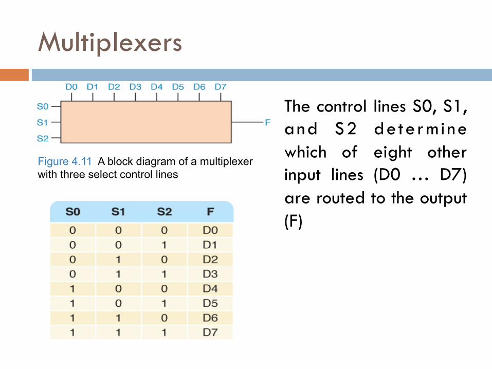
Multiplexers
The control lines S0, S1, and S2 determine which of eight other input lines (D0 … D7) are routed to the output (F)
Figure 4.11 A block diagram of a multiplexer with three select control lines

Circuits as Memory
¨ Digital circuits can be used to store information ¨ These circuits form a sequential circuit, because the
output of the circuit is also used as input to the circuit

Circuits as Memory
¨ An S-R latch stores a single binary digit (1 or 0)
¨ There are several ways an S-R latch circuit can be designed using various kinds of gates
Figure 4.12 An S-R latch

Circuits as Memory
¨ The design of this circuit guarantees that the two outputs X and Y are always complements of each other
¨ The value of X at any point in time is considered to be the current state of the circuit
¨ Therefore, if X is 1, the circuit is storing a 1; if X is 0, the circuit is storing a 0
Figure 4.12 An S-R latch

Integrated Circuits
¨ Integrated circuit (also called a chip) ¤ A piece of silicon on which multiple gates have been
embedded ¤ Silicon pieces are mounted on a plastic or ceramic
package with pins along the edges that can be soldered onto circuit boards or inserted into appropriate sockets

Integrated Circuits
¨ Integrated circuits (IC) are classified by the number of gates contained in them

Integrated Circuits
Figure 4.13 An SSI chip contains independent NAND gates
CPU Chips
¨ The most important integrated circuit in any computer is the Central Processing Unit, or CPU
¨ Each CPU chip has a large number of pins through which essentially all communication in a computer system occurs

Computer Components
Consider the following ad: Insatavialion 640 Laptop Exceptional Performance and Portability • Intel® Core™ 2 Duo (2.66GHz/1066MHz FSB/6MB cache) • 15.6” High Definition (1080p) LED Backlit LCD Display (1366 x 768) • 512MB ATI Mobility Radeon Graphics • Built-in 2.0MP Web Camera • 4GB Shared Dual Channel DDR2 at 800MHz • 500GB SATA Hard Drive at 5400RPM • 8X Slot Load DL DVD+/- RW Drive • 802.11 a/g/n and Bluetooth 3.0
• 85 WHr Lithium Ion Battery • (2) USB 2.0, HDMI, 15-pin VGA, Ethernet 10/100/1000, IEEE 1394 Firewire, Express Card, Audio line-in, line-out, mic-in • 14.8W X 1.2H X 10.1D, 5.6 lbs • Microsoft0® Windows 7® Professional • Microsoft® Office Home and Student 2007 • 36-Month subscription to McAfee Security Center Anti-virus

Computer Components
¨ What does all this jargon mean? ¤ Intel® Core™ 2 Duo (2.66GHz/1066MHz FSB/6MB cache) ¤ 4GB Shared Dual Channel DDR2 at 800 MHz ¤ 500 GB SATA Hard Drive at 5400RPM ¤ 15.6” High Definition (1080p) LED Backlit LCD Display (1366 x 768) ¤ 8X Slot Load DL DVD+/- RW Drive ¤ 14.8”W X 1.2”H X10.1” D, 5.6 lbs.

Computer Components (continued)
¤ 512 MB ATI Mobility Radeon Graphics ¤ 85 WHr Lithium Ion Battery ¤ (2) USB 2.0, HDMI, 15-Pin VGA, Ethernet 10/100/1000 IEEE 1394
Firewire, Express Card, Audio line-in, line-out, mic-in ¤ Microsoft® Windows 7® Professional ¤ Microsoft® Office Home and Student 2007 ¤ 36-Month subscription to McAfee Security Center Anti-virus

Sizes in Perspective
What is a hertz?

Sizes in Perspective
¨ Intel Processor ¤ Speed 2.66 GHz
¨ SDRAM ¤ Size 4GB ¤ Speed 800 MHz
¨ 500GB SATA at 5400 RPM ¤ Transfer rate 300MB per second
¨ Flat screen dot pitch .28mm
To which do these apply? Bigger is better Faster is better Smaller is better

Stored-Program Concept
Figure 5.1 The von Neumann architecture

Memory
¨ Memory ¤ A collection of cells, each
with a unique physical address
¤ Both addresses and contents are in binary

Arithmetic/Logic Unit
¨ Performs basic arithmetic operations such as adding ¨ Performs logical operations such as AND, OR, and
NOT ¨ Most modern ALUs have a small amount of special
storage units called registers

Input/Output Units
¨ Input Unit ¤ A device through which data and programs from the
outside world are entered into the computer ¤ Can you name three?
¨ Output unit ¤ A device through which results stored in the computer
memory are made available to the outside world ¤ Can you name two?

Control Unit
¨ Control unit ¤ The organizing force in the computer
¨ Instruction register (IR) ¤ Contains the instruction that is being executed
¨ Program counter (PC) ¤ Contains the address of the next instruction to be
executed ¨ Central Processing Unit (CPU)
¤ ALU and the control unit called the Central Processing Unit, or CPU

Flow of Information
¨ Bus ¤ A set of wires that connect all major sections
Figure 5.2 Data flow through a von Neumann architecture

The Fetch-Execute Cycle
¨ Fetch the next instruction ¨ Decode the instruction ¨ Get data if needed ¨ Execute the instruction

The Fetch-Execute Cycle
Figure 5.3 The Fetch-Execute Cycle

RAM and ROM
¨ Random Access Memory (RAM) ¤ Memory in which each location can be accessed and
changed
¨ Read Only Memory (ROM) ¤ Memory in which each location can be accessed but not
changed
¨ RAM is volatile, ROM is not ¨ What does volatile mean?

Secondary Storage Devices
¨ Why is it necessary to have secondary storage devices?
¨ Can you name some of these devices?

Magnetic Tape
¨ The first truly mass auxiliary storage device was the magnetic tape drive
¨ Tape drives have a major problem; can you describe it?
Figure 5.4 A magnetic tape

Magnetic Disks
Figure 5.5 The organization of a magnetic disk

Magnetic Disks
¨ History ¤ Floppy disks
n 1970, 8" in diameter n Late 1970, 5 1/4” n Now, 3 1/2”
¤ Zip drives
¨ Tracks near center are more densely packed

Magnetic Disks
¨ Seek time ¤ Time it takes for read/write head to be over right track
¨ Latency ¤ Time it takes for sector to be in position
¨ Access time ¤ Can you define it?

Compact Disks
¨ CD ¤ A compact disk that uses a laser to read information
stored optically on a plastic disk ¤ Data is evenly distributed around track ¤ CD-ROM read-only memory ¤ CD-DA digital audio ¤ CD-WORM write once, read many ¤ CD-RW or RAM both read from and written to
¨ DVD ¤ Digital Versatile Disk, used for storing audio and video

Flash Drives
¨ Flash Memory ¤ Nonvolatile ¤ Can be erased and rewritten

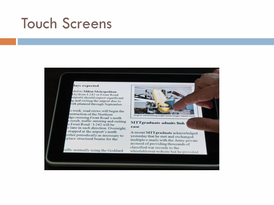
Touch Screens
¨ Touch screen ¤ A computer monitor that can respond to the user,
touching the screen with a stylus or finger
¨ There are different types ¤ Resistive ¤ Capacitive ¤ Infrared ¤ Surface acoustic wave (SAW)
Touch Screens

Touch Screens
¨ Resistive touch screen ¤ A screen made up of two layers of electrically
conductive material ¤ One layer has vertical lines, the other has horizontal
lines ¤ When the top layer is pressed, it comes in contact with
the second layer which allows electrical current to flow ¤ The specific vertical and horizontal lines that make
contact dictate the location on the screen that was touched

Touch Screens
¨ Capacitive touch screen ¤ A screen made up of a laminate applied over a glass
screen ¤ Laminate conducts electricity in all directions; a very
small current is applied equally on the four corners ¤ When the screen is touched, current flows to the finger
or stylus ¤ The location of the touch on the screen is determined by
comparing how strong the flow of electricity is from each corner
Touch Screens
¨ Infrared touch screen ¤ A screen with crisscrossing horizontal and vertical
beams of infrared light ¤ Sensors on opposite sides of the screen detect the
beams ¤ When the user breaks the beams by touching the
screen, the location of the break can be determined

Touch Screens
¨ Surface acoustic wave (SAW) ¤ A screen with crisscrossing high frequency sound waves
across the horizontal and vertical axes ¤ When a finger touches the surface, corresponding
sensors detect the interruption and determine location of the touch

Embedded Systems
¨ Embedded systems ¤ Computers that are dedicated to perform a narrow
range of functions as part of a larger system
¨ Empty your pockets or backpacks ¤ How many embedded systems do you have?

Parallel computing
¨ If a problem can be solved in n time units on a computer with one procesor, can it be solved in n/2 times units on a computer with two processors? ¤ YES? ¤ NO?

Synchronous processing
¨ One approach to parallelism is to have multiple processors apply the same program to multiple data sets
Figure 5.8 Processors in a synchronous computing environment

Pipelining
¨ Arranges processors in tandem, where each processor contributes one part to an overall computation
Figure 5.9 Processors in a pipeline

Shared Memory Parallel Processor
¨ Communicate through shared memory
Figure 5.10 Shared memory configuration of processors
Picture sources of today’s slides
¨ Jones & Barlett Learning’s slides
¨ Prof. Jaehoon Jeong’s slides
¨ http://www.computerhope.com/jargon/c/connect.htm
¨ http://enigma777.egloos.com/3279151
¨ http://ko.wikipedia.org/wiki/%ED%94%8C%EB%A1%9C%ED%94%BC_%EB%94%94%EC%8A%A4%ED%81%AC