Fused Deposition Modeling of Metals
10
Fused Deposition Modeling of Metals Jorge Mireles 1 , David Espalin 1 , David Roberson 1 , Bob Zinniel 2 , Francisco Medina 1 , Ryan Wicker 1 1. W.M. Keck Center for 3D Innovation, The University of Texas at El Paso, El Paso, TX 2. Stratasys, Inc., Eden Prairie, MN Abstract Studies have been conducted to improve previous work performed in developing a Fused Deposition Modeling for metals (FDMm) system used for applications in electronics and fabrication of 3-dimensional metallic structures. A FDM 3000 system was modified to achieve controlled deposition of eutectic Bi58Sn42 and non-eutectic Sn60Bi40 materials. Toolpath command modifications were required to achieve controlled deposition of metals. Results are presented which include a redesigned metal deposition head, computer modeling of fluid flow, and finally examples of the successful deposition of metal alloys. Additionally, FDMm- fabricated metal samples were prepared and analyzed using optical and scanning electron microscopy. Controlled deposition of metals using FDMm allows for parts that can be used for jigs and fixtures, electroforming mandrels, encapsulation molds, dies, electronic joining applications, as well as printing 3-dimensional electronic circuitry. 1 Introduction Additive manufacturing (AM) allows complex parts to be built without the need for tooling, dies, or molds, using little human intervention. Fused Deposition Modeling (FDM) technology is an AM process that builds 3D shapes by taking filaments of thermoplastic polymer materials and driving them into a heated liquefier to be extruded through a small diameter nozzle onto a build platform. Technologies capable of processing metals include, for example, electron beam melting, direct metal laser sintering, laser engineered net shaping and selective laser melting. Utilizing FDM technology to extrude metals poses advantages and disadvantages when compared to methods that currently build using metal alloys. An advantage of using FDM is the lack of expensive lasers equipped in sintering processes or an electron beam as is present in the electron beam melting process. Less expensive materials and systems are available that use FDM technology compared to sintering and melting technologies. A difference is also the ability to build using both thermoplastics and metals within the same build which is not possible with other direct metal systems. Disadvantages include the limitation to low-temperature, low- strength, alloys as well as the possibility for oxidation during the build process due to the lack of a controlled environment. Extending FDM to be able to process metal alloys, called FDM for metals (FDMm), has been the subject of previous work where successful deposition of tin- bismuth (Sn60Bi40 and Bi58Sn42) alloys was demonstrated (Mireles et al., 2012) . Prior research in metallic FDM with metal/polymer filaments showed successful fabrication of 3D structures (Masood and Song, 2004; Agarwala et al., 1996); however, the parts were shown to possess insufficient material properties, such as conductivity, as compared to the bulk or pure alloys (i.e. metals without a polymer binder). The research presented here utilizes a Stratasys FDM 3000 system to deposit low melting temperature (T m ) alloys (i.e. alloys of T m below ~300 o C), similar to the system described in Mireles et al., 2012. Drawbacks in the system described in Mireles et al., 2012, include a liquefier design which presents unnecessary frictional effects due to a 90 o bend and liquefier length which poses start/stop deposition issues with the 836
Transcript of Fused Deposition Modeling of Metals
Fused Deposition Modeling of Metals
Jorge Mireles
1, David Espalin
1, David Roberson
1, Bob Zinniel
2, Francisco Medina
1, Ryan Wicker
1
1. W.M. Keck Center for 3D Innovation, The University of Texas at El Paso, El Paso, TX
2. Stratasys, Inc., Eden Prairie, MN
Abstract
Studies have been conducted to improve previous work performed in developing a Fused
Deposition Modeling for metals (FDMm) system used for applications in electronics and
fabrication of 3-dimensional metallic structures. A FDM 3000 system was modified to achieve
controlled deposition of eutectic Bi58Sn42 and non-eutectic Sn60Bi40 materials. Toolpath
command modifications were required to achieve controlled deposition of metals. Results are
presented which include a redesigned metal deposition head, computer modeling of fluid flow,
and finally examples of the successful deposition of metal alloys. Additionally, FDMm-
fabricated metal samples were prepared and analyzed using optical and scanning electron
microscopy. Controlled deposition of metals using FDMm allows for parts that can be used for
jigs and fixtures, electroforming mandrels, encapsulation molds, dies, electronic joining
applications, as well as printing 3-dimensional electronic circuitry.
1 Introduction
Additive manufacturing (AM) allows complex parts to be built without the need for
tooling, dies, or molds, using little human intervention. Fused Deposition Modeling (FDM)
technology is an AM process that builds 3D shapes by taking filaments of thermoplastic polymer
materials and driving them into a heated liquefier to be extruded through a small diameter nozzle
onto a build platform. Technologies capable of processing metals include, for example, electron
beam melting, direct metal laser sintering, laser engineered net shaping and selective laser
melting. Utilizing FDM technology to extrude metals poses advantages and disadvantages when
compared to methods that currently build using metal alloys. An advantage of using FDM is the
lack of expensive lasers equipped in sintering processes or an electron beam as is present in the
electron beam melting process. Less expensive materials and systems are available that use
FDM technology compared to sintering and melting technologies. A difference is also the ability
to build using both thermoplastics and metals within the same build which is not possible with
other direct metal systems. Disadvantages include the limitation to low-temperature, low-
strength, alloys as well as the possibility for oxidation during the build process due to the lack of
a controlled environment. Extending FDM to be able to process metal alloys, called FDM for
metals (FDMm), has been the subject of previous work where successful deposition of tin-
bismuth (Sn60Bi40 and Bi58Sn42) alloys was demonstrated (Mireles et al., 2012) . Prior
research in metallic FDM with metal/polymer filaments showed successful fabrication of 3D
structures (Masood and Song, 2004; Agarwala et al., 1996); however, the parts were shown to
possess insufficient material properties, such as conductivity, as compared to the bulk or pure
alloys (i.e. metals without a polymer binder). The research presented here utilizes a Stratasys
FDM 3000 system to deposit low melting temperature (Tm) alloys (i.e. alloys of Tm below
~300oC), similar to the system described in Mireles et al., 2012. Drawbacks in the system
described in Mireles et al., 2012, include a liquefier design which presents unnecessary frictional
effects due to a 90o bend and liquefier length which poses start/stop deposition issues with the
836
bjf
Typewritten Text
REVIEWED, Accepted August 22, 2012
molten droplets as has been prevalent in microdispensing techniques (Bellini and Bertoldi, 2004;
Bellini, 2002).
The work presented here extends the concepts described in Mireles et al., 2012 to more
effectively deposit low Tm metal alloys using a redesigned deposition head. The redesigned
liquefier was conceived using current liquefier designs of machines currently produced by
Stratasys (FDM Titan, FDM Maxum, 400mc, 900mc) as well as 3D printers which use the
concepts of FDM and use straight liquefier configurations (MakerBot, 3DTouch). Previous work
by Rice et al. 2000 has attempted to deposit low Tm metals using a modified design that
implements a rheocast liquefier that uses the basic FDM process of layer-to-layer stacking with
metal slurries of binary alloys instead of a wire feed process. However, the layer thickness
produced using the rheocast liquefier system only achieves layer thickness on the order of
3.5mm (0.135in). Modifications of temperature, flow parameters, as well as toolpath commands
have been modified to achieve controlled deposition. Flow modeling of both the redesigned and
the original liquefier design are discussed with experimental results as well as possible ways to
implement such designs with high temperature alloys. Metallographic images have been taken to
observe the microstructure of parts built using FDMm and determine possible implications or
advantages of using a FDMm system to build both electronic circuitry and 3D parts. The
applications that can benefit from low Tm metal alloys include building jigs and fixtures,
electroforming mandrels, encapsulation molds, dies, electronic joining applications, as well as
printing 3-Dimensional circuitry (Ojebuoboh, 1992; White and Ferriter, 1990). The following
describes the design and development of the redesigned FDMm liquefier, fluid flow modeling
comparing original and redesigned liquefiers, followed by deposition results, and a successful
example of the fabrication of a 3D object.
2 Design and concept
A FDM 3000 system (Stratasys, Inc., Eden Prairie, MN) was used in this research due to
its ability to alter build parameters such as deposition head motion speed, material flow rates,
chamber and liquefier temperatures, and toolpath commands. Modern FDM systems, such as the
Fortus 900mc and 400mc, include a straight liquefier configuration that formed the basis for a
redesign of the FDM 3000 head. Figure 1(a) shows the original configuration for a FDM 3000
deposition head and Figure 1(b) shows the redesigned liquefier implemented in this research.
Figure 1: FDM head of a) original liquefier design and b) redesigned liquefier
showing difference in liquefier configuration (note that the original liquefiers is curved
while the redesigned liquefier is straight as highlighted by red dashed lines)
a) b)
liquefier heating coils
nozzle
stepper motors
837
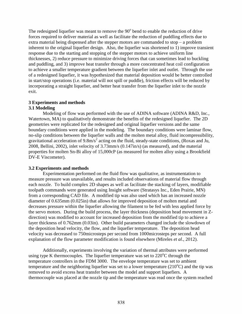
The redesigned liquefier was meant to remove the 90o bend to enable the reduction of drive
forces required to deliver material as well as facilitate the reduction of puddling effects due to
extra material being dispensed after the stepper motors are commanded to stop – a problem
inherent to the original liquefier design. Also, the liquefier was shortened to 1) improve transient
response due to the starting and stopping of the stepper motors to achieve uniform line
thicknesses, 2) reduce pressure to minimize driving forces that can sometimes lead to buckling
and puddling, and 3) improve heat transfer through a more concentrated heat coil configuration
to achieve a smaller temperature gradient between the liquefier inlet and outlet. Through the use
of a redesigned liquefier, it was hypothesized that material deposition would be better controlled
in start/stop operations (i.e. material will not spill or puddle), friction effects will be reduced by
incorporating a straight liquefier, and better heat transfer from the liquefier inlet to the nozzle
exit.
3 Experiments and methods
3.1 Modeling
Modeling of flow was performed with the use of ADINA software (ADINA R&D, Inc.,
Watertown, MA) to qualitatively demonstrate the benefits of the redesigned liquefier. The 2D
geometries were replicated for the redesigned and original liquefier versions and the same
boundary conditions were applied in the modeling. The boundary conditions were laminar flow,
no-slip conditions between the liquefier walls and the molten metal alloy, fluid incompressibility,
gravitational acceleration of 9.8m/s2 acting on the fluid, steady-state conditions, (Roxas and Ju,
2008, Bellini, 2002), inlet velocity of 3.73mm/s (0.147in/s) (as measured), and the material
properties for molten Sn-Bi alloy of 15,000cP (as measured for molten alloy using a Brookfield
DV-E Viscometer).
3.2 Experiments and methods
Experimentation performed on the fluid flow was qualitative, as instrumentation to
measure pressure was unavailable, and results included observations of material flow through
each nozzle. To build complex 2D shapes as well as facilitate the stacking of layers, modifiable
toolpath commands were generated using Insight software (Stratasys Inc., Eden Prairie, MN)
from a corresponding CAD file. A modified tip was also used which has an increased nozzle
diameter of 0.635mm (0.025in) that allows for improved deposition of molten metal and
decreases pressure within the liquefier allowing the filament to be fed with less applied force by
the servo motors. During the build process, the layer thickness (deposition head movement in Z-
direction) was modified to account for increased deposition from the modified tip to achieve a
layer thickness of 0.762mm (0.03in). Other build parameters changed include the slowdown of
the deposition head velocity, the flow, and the liquefier temperature. The deposition head
velocity was decreased to 750microsteps per second from 1000microsteps per second. A full
explanation of the flow parameter modification is found elsewhere (Mireles et al., 2012).
Additionally, experiments involving the variation of thermal attributes were performed
using type K thermocouples. The liquefier temperature was set to 220oC through the
temperature controllers in the FDM 3000. The envelope temperature was set to ambient
temperature and the neighboring liquefier was set to a lower temperature (210oC) and the tip was
removed to avoid excess heat transfer between the model and support liquefiers. A
thermocouple was placed at the nozzle tip and the temperature was read once the system reached
838
steady temperature conditions. The liquefier temperature was set to 210oC for the eutectic alloy
Bi58Sn42 and 220oC for the non-eutectic alloy Sn60Bi40. These temperatures account for a
temperature difference from the heat supplied to the liquefier by the heating coils to the heat
conducted to the nozzle end.
Scanning electron microscopy (SEM) was performed with a Hitachi S-4800 Ultra-high
Resolution Field Emission Scanning Electron Microscope (Hitachi High-Technologies
Corporation, Tokyo, Japan) equipped with an EDAX energy dispersive X-ray analyzer (EDS)
and utilizing a 20keV accelerating voltage. Optical metallography was performed using a Leica
MEF4M optical digital imaging system on a mounted sample of stacked layers built using the
FDMm system. Metallography was performed on the mounted samples using 400grit, 1000grit,
and 1200grit paper, followed by a finishing step with a polishing cloth using 0.3µ alumina slurry.
An etchant composed of 10% HCl and 90%H2O was applied to reveal the microstructure.
4 Results
4.1 Modeling results
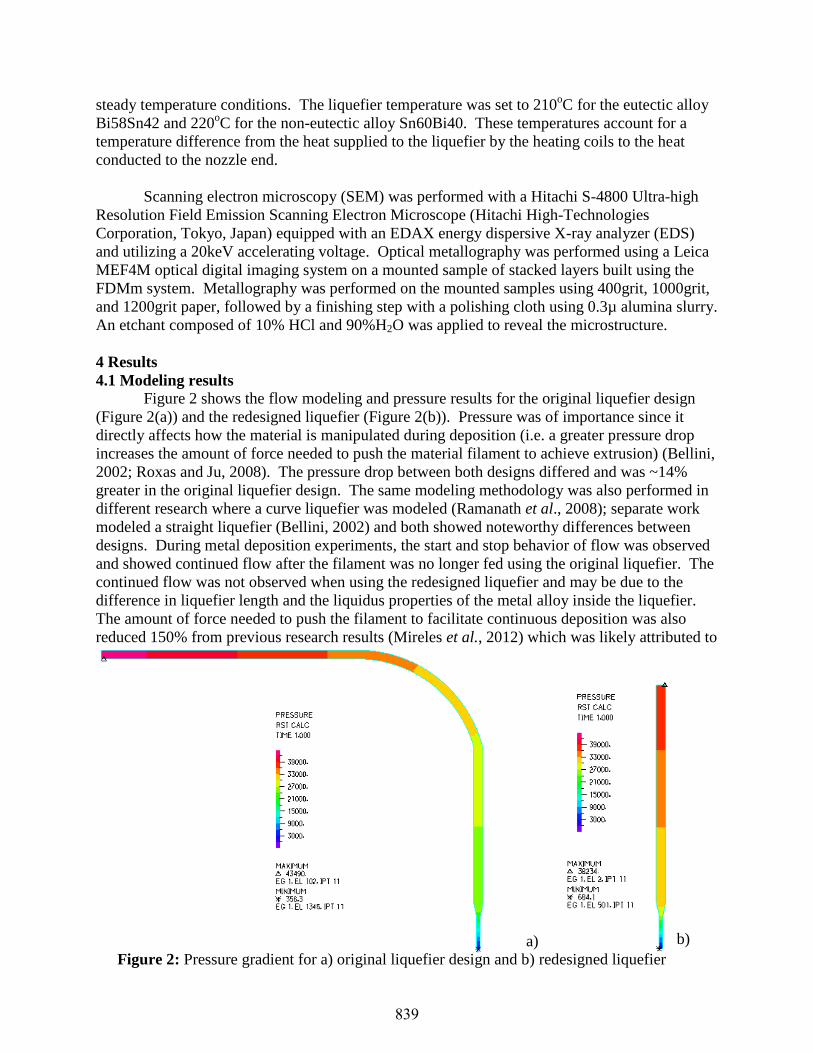
Figure 2 shows the flow modeling and pressure results for the original liquefier design
(Figure 2(a)) and the redesigned liquefier (Figure 2(b)). Pressure was of importance since it
directly affects how the material is manipulated during deposition (i.e. a greater pressure drop
increases the amount of force needed to push the material filament to achieve extrusion) (Bellini,
2002; Roxas and Ju, 2008). The pressure drop between both designs differed and was ~14%
greater in the original liquefier design. The same modeling methodology was also performed in
different research where a curve liquefier was modeled (Ramanath et al., 2008); separate work
modeled a straight liquefier (Bellini, 2002) and both showed noteworthy differences between
designs. During metal deposition experiments, the start and stop behavior of flow was observed
and showed continued flow after the filament was no longer fed using the original liquefier. The
continued flow was not observed when using the redesigned liquefier and may be due to the
difference in liquefier length and the liquidus properties of the metal alloy inside the liquefier.
The amount of force needed to push the filament to facilitate continuous deposition was also
reduced 150% from previous research results (Mireles et al., 2012) which was likely attributed to
Figure 2: Pressure gradient for a) original liquefier design and b) redesigned liquefier
a) b)
839

lowering the pressure with the redesigned liquefier. Additionally, experimentation performed
utilizing type K thermocouples showed a difference between the temperature set by the operator
(220oC) to the temperature at the nozzle of 65
oC for the original liquefier design compared to
48oC for the redesigned liquefier demonstrating improved precision.
Using ideal conditions, the simulation results for pressure still showed a notable
difference between both designs. The non-ideal conditions including frictional effects, slip
between the liquefier walls and the filament, as well as uneven heat distribution, can produce a
greater difference between the two liquefier designs and demonstrates the need for a straight
liquefier design as this design minimizes the non-ideal conditions. Further emphasizing the need
for a straight liquefier design is the fact that similar designs are already used in newer FDM
models.
4.2 Deposition results
To demonstrate the improved capability of the redesigned liquefier as well as the effect of
code modifications and liquefier temperature changes, 2D and 3D structures were fabricated and
are shown in Figure 3(a) and Figure 3(b), respectively. As shown, layer stacking was achieved
and parts were created using metal alloys of low Tm. Road width of the layers using eutectic
material was 1.24mm (0.049in) and layer thickness was 0.74mm (0.029in). For non-eutectic
material, road width was 1.12mm (0.44in) and layer thickness was 0.71mm (0.028in). As
Bi58Sn42 Sn60Bi40 ABS
Z Thickness, µ±σ
(mm (inch))
0.74± 0.13
(0.029±0.0051)**
0.71±0.061
(0.028±0.0024)**
0.254 (0.010)*
Road Width, µ±σ
(mm (inch))
1.24±0.19
(0.049±0.0078)**
1.12±0.12
(0.044±0.0045)**
0.76 (0.030)*
System Temperature (°C) 210°C(428°F)** 220°C(446°F)** 270°C(518°F)*
Tensile Strength (MPa) 51.7*** 52.5*** 22***
Elongation at Break (%) 35*** 35*** 6***
*According to system specifications, standard deviation not available
**According to deposition results
*** According to manufacturer information
Table 1: Comparison of 10 single layers each of Sn-Bi or ABS
6.35mm b)
Figure 3: Demonstration of deposition results using FDMm where a) shows an example of
2D shapes and b) shows a 3D structure of 6 stacked layers.
a)
840
demonstrated in previous research(Mireles et al., 2012), non-eutectic materials deposited better
than eutectic materials and it was also demonstrated here by observing the standard deviation
between single lines of deposited material in Table 1.
Results of the deposition of low Tm metallic materials also extend to the continuity and
thickness uniformity throughout the deposited lines. As shown in Figure 3, the lines for both 2D
and 3D parts are continuous throughout. It was previously hypothesized that non-eutectic
materials are more suitable for FDM due to the presence of a “mushy” zone which allows for a
higher viscosity and therefore deposition was more controlled and continuous (Mireles et al.,
2012, White and Ferriter, 1990). The results in Table 1 showed little difference between both
eutectic and non-eutectic materials, however, non-eutectic lines still showed less variance in
thickness throughout the length of a deposited line. Although non-eutectic alloys still perform
better than eutectic compositions, the redesigned liquefier improves the deposition of eutectic
alloys.
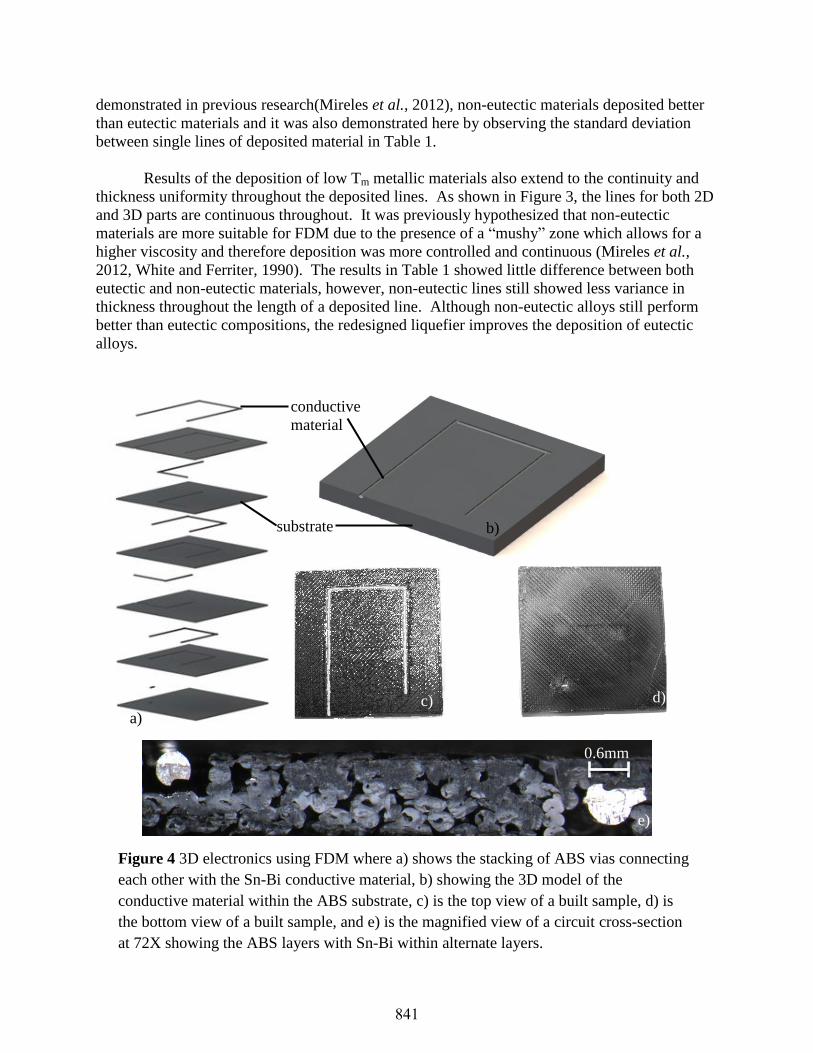
conductive
material
substrate
Figure 4 3D electronics using FDM where a) shows the stacking of ABS vias connecting
each other with the Sn-Bi conductive material, b) showing the 3D model of the
conductive material within the ABS substrate, c) is the top view of a built sample, d) is
the bottom view of a built sample, and e) is the magnified view of a circuit cross-section
at 72X showing the ABS layers with Sn-Bi within alternate layers.
a)
b)
c) d)
e)
0.6mm
841
A potential application for FDMm is the building of 3D circuitry that allows for electrical
components to be connected on different faces of a solid. Figure 4 demonstrates the ability for
the support liquefier in the deposition head shown in Figure 1 to deposit a substrate and for the
model liquefier to deposit the conductive material that connects to each layer through vias in the
substrate material. Figures 4(a) and 4(b) show the CAD demonstration of the model while
Figures 4(c) and 4(d) represent the actual deposition results. Figure 4(e) shows a magnified view
taken with a stereomicroscope magnified at 72X of two subsequent layers showing Sn-Bi
material filling the ABS via. Figure 4 only showed contacts between layers without electronic
components; however, cavities which allow for component placement can be produced as
demonstrated by Lopes et al. 2012 where stereolithography was used in the creation of 3D
structural electronics.
4.3 Microstructural analysis
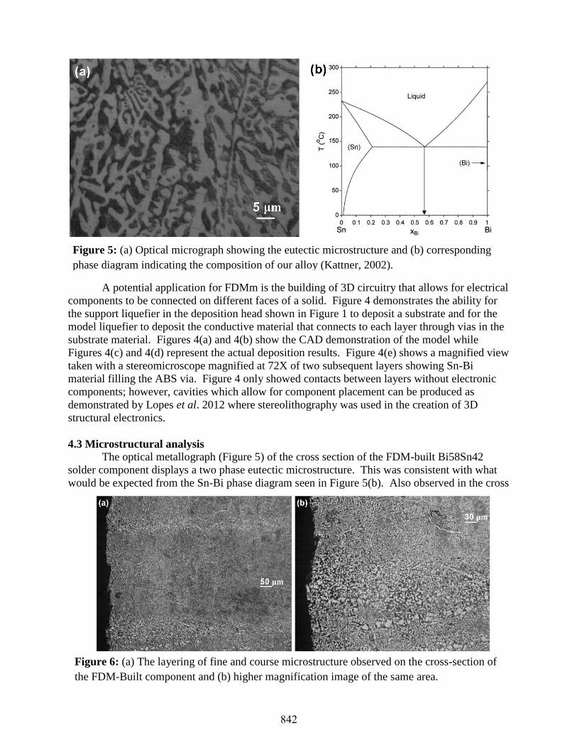
The optical metallograph (Figure 5) of the cross section of the FDM-built Bi58Sn42
solder component displays a two phase eutectic microstructure. This was consistent with what
would be expected from the Sn-Bi phase diagram seen in Figure 5(b). Also observed in the cross
Figure 5: (a) Optical micrograph showing the eutectic microstructure and (b) corresponding
phase diagram indicating the composition of our alloy (Kattner, 2002).
Figure 6: (a) The layering of fine and course microstructure observed on the cross-section of
the FDM-Built component and (b) higher magnification image of the same area.
842
section (Figure 6) is a layering effect of fine and coarse microstructure which was most-likely
due to the build process.
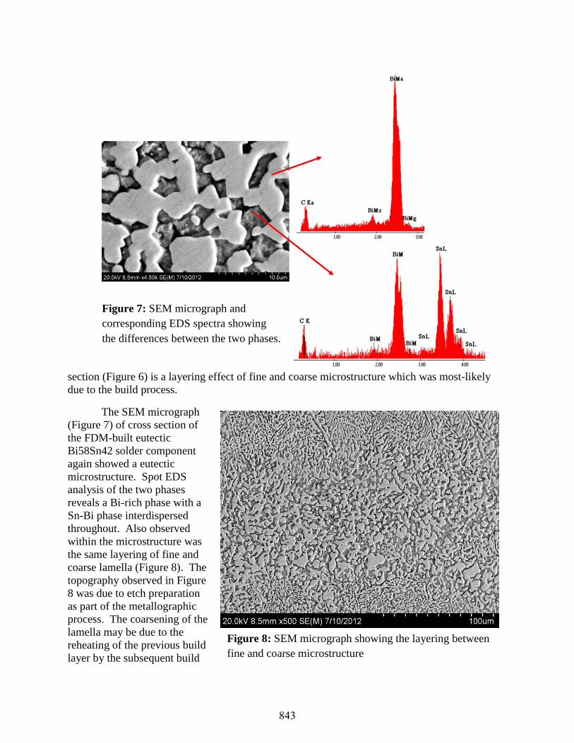
The SEM micrograph
(Figure 7) of cross section of
the FDM-built eutectic
Bi58Sn42 solder component
again showed a eutectic
microstructure. Spot EDS
analysis of the two phases
reveals a Bi-rich phase with a
Sn-Bi phase interdispersed
throughout. Also observed
within the microstructure was
the same layering of fine and
coarse lamella (Figure 8). The
topography observed in Figure
8 was due to etch preparation
as part of the metallographic
process. The coarsening of the
lamella may be due to the
reheating of the previous build
layer by the subsequent build
Figure 7: SEM micrograph and
corresponding EDS spectra showing
the differences between the two phases.
Figure 8: SEM micrograph showing the layering between
fine and coarse microstructure
843
layer. In the context of a structural part, the coarsening of the eutectic microstructrure has been
observed to improve the mechanical properties of Sn-Bi alloys used in various applications of
low Tm alloys (Felton et al. 1993). In the context of the electric circuit presented here the
coarsening may also be beneficial as, in general, a metallic conductive path with large grains will
have better conductivity than the same material with small grains as grain boundaries act as
detractors to the flow of electrons (Roberson, 2012).
Conclusions
Through the use of a FDM 3000 system, controlled deposition of metal alloys has been
achieved and 3D structures have been built in a layered fashion using a redesigned liquefier.
Idealistic modeling was done to evaluate the performance difference between the original
liquefier and the redesigned liquefier. Assuming ideal conditions there were notable differences
that exemplify the need for an improved liquefier design. Experimental measurements and
deposition results further demonstrated the superior performance of the redesigned liquefier over
the original liquefier. Various applications can benefit from metallic FDM including building
jigs and fixtures, electroforming mandrels, encapsulation molds, dies, electronic joining
applications, as well as printing 3-Dimensional circuitry. Microstructural analysis demonstrated
good interlayer bonding with variations in the coarseness of microstructure along the layer
interface that affects mechanical and conductive properties. The results of this work give
potential to utilize the redesigned FDMm configuration with different deposition head materials
to build metallic components using higher strength alloys.
Future Work
Further work can be extended to provide results using higher Tm metals which have
potential applications in the fabrication of structural parts using the same methodology explored
in this research. Accuracy has improved with the implementation of a redesigned deposition
head; however, improvements are required to achieve accuracies equivalent to those achieved by
polymers such as ABS (+-0.005). The fabrication of more complex 3D structures needs to be
demonstrated and the microstructure and interfacial phenomena between layers for such
structures needs to be analyzed. For 3D circuits, a fully-functional circuit needs to be
demonstrated with cavities for electronic component placement. Control of microstructure may
be accomplished by close control of temperature parameters to obtain favorable microstructures
(coarsening) for maximum mechanical properties as well as uniform conductivity.
Acknowledgements
The research described in this paper was performed within the W.M. Keck Center for 3D
Innovation at the University of Texas at El Paso (UTEP). Additional support was provided by
the UTEP Louise Stokes Alliance for Minority Participation program funded through grant
number HRD-1139929 from the National Science Foundation. The findings and opinions
presented in this paper are those of the authors and do not necessarily reflect those of the
sponsors of this research.
844
References
Agarwala, M. K., Weeren, R. V., Bandyopadhyay, A., Whalen, P. J., Safari, A., and Danforth, S. C.,
(1996), Fused Deposition of ceramics and metals: an overview. Proceedings of the Solid
Freeform Fabrication Symposium, Austin, Texas.
Bellini A., and Bertoldi M., (2004). Liquefier dynamics in fused deposition modeling,” Journal of
Manufacturing Science and Engineering, 126, pp. 237-246.
Bellini A., (2002). Fused deposition of ceramics: A comprehensive experimental, analytical and
computational study of material behavior, fabrication process and equipment design. Ph.D.
Dissertation, Philadelphia, USA: Drexel University.
Chua, C.K., Leong, K.F., and Lim, C.S., (2003), Rapid prototyping: principles and applications, Singapore, World Scientific Publishing Co.
Felton, L., Raeder, C. & Knorr, D. (1993).The properties of tin-bismuth alloy solders. JOM Journal of the
Minerals, Metals and Materials Society 45, 28–32.
Finke, S., Feenstra, F.K., (2002). Solid Freeform fabrication by extrusion and deposition of semi-solid
alloys. Journal of Materials Science, 37, pp. 3101-3106.
Kattner, U.R., (2002). Phase diagrams for lead-free solder alloys. Journal of Materials. 54 (45). pp.45-50.
Lopes, A.J., MacDonald, E., Wicker, R., (2012). Integrating stereolithography and direct print
technologies for 3D structural electronics fabrication. Rapid Prototyping Journal, 18 (2), pp.129-
143.
Masood, S., and Song, W.Q., (2004). Development of new metal/polymer materials for rapid tooling
using fused deposition modeling. Materials & Design, 25(7), pp. 587-594.
Mireles, J., Kim, H., Lee, I.H., Espalin, D., Medina, F., MacDonald, E., Wicker, R., (2012). Development
of a Fused Deposition Modeling system for low temperature metal alloys. Journal of Electronic
Packaging.
Ojebuoboh, F.K., (1992). Bismuth-Production, properties, and applications. Journal of Materials: 1992
Review of Extractive Metallurgy, 44 (4), pp.46-49.
Ramanath, H.S., Chua, C.K., Leong, K.F., Shah, K.D.,(2008). Melt flow behavior of poly-ε-caprolactone
in fused deposition modeling. Journal of Materials Science, 19 (7), pp. 2541-2550.
Roxas, M., Ju, S., (2008). Fluid dynamics analysis of desktop-based fused deposition modeling rapid
prototyping. Department of Mechanical and Industrial Engineering, University of Toronto.
Rice, C.S., Mendez, P.F., Brown, S.B., (2000). Metal solid freeform fabrication using semi-solid slurries.
Journal of Minerals, Metals, and Materials Society, 52 (12), pp. 31-33.
Roberson, D. A. Dissertation, The University of Texas at El Paso, (2012)
White, C.E.T., Ferriter, J.M., (1990). How to use fusible alloys. Machine Design, 62 (25), pp. 124-131.
845