
Frog Plus Tech Doc
18
SERIES FROG PLUS INSTALLATION MANUAL FROG-PM BELOW SURFACE SWING-GATE OPERATOR English EN
Transcript of Frog Plus Tech Doc

SE
RIE
S F
ROG
PLUS
INSTALLATION MANUAL
FROG-PM
BELOW SURFACE SWING-GATE OPERATOR
English EN
P. 22
- M
anual
cod
e: 1
19
AV
70
119
AV
70
ver
. 1
.01
.0 0
3/2
011
© C
AM
E ca
nce
lli a
utom
atic
i s.p
.a.
- Th
e dat
a an
d in
form
atio
n in
this
man
ual
may
be
chan
ged
at
any
time
and
with
out
oblig
atio
n on
the
par
t of
Cam
e C
ance
lli A
utom
atic
i S.p
.a.
to n
otify
sai
d ch
anges
.
EN
GLIS
H
Index
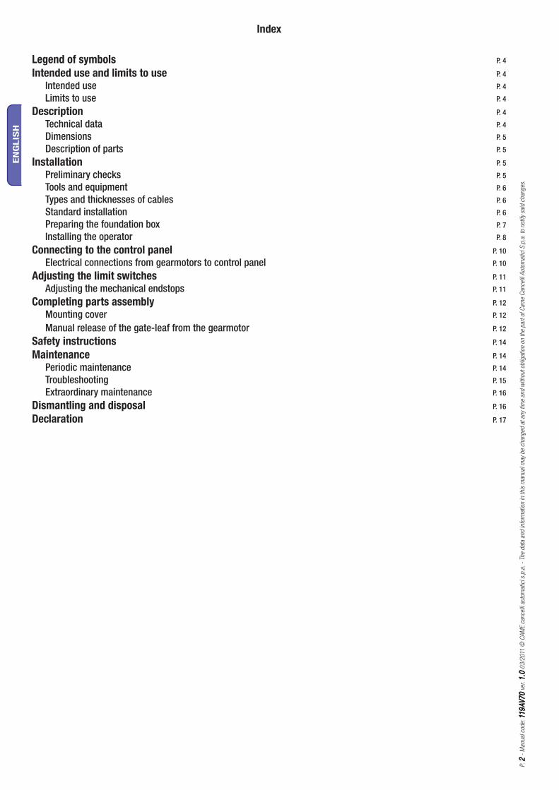
Legend of symbols P. 4
Intended use and limits to use P. 4
Intended use P. 4
Limits to use P. 4
Description P. 4
Technical data P. 4
Dimensions P. 5
Description of parts P. 5
Installation P. 5
Preliminary checks P. 5
Tools and equipment P. 6
Types and thicknesses of cables P. 6
Standard installation P. 6
Preparing the foundation box P. 7
Installing the operator P. 8
Connecting to the control panel P. 10
Electrical connections from gearmotors to control panel P. 10
Adjusting the limit switches P. 11
Adjusting the mechanical endstops P. 11
Completing parts assembly P. 12
Mounting cover P. 12
Manual release of the gate-leaf from the gearmotor P. 12
Safety instructions P. 14
Maintenance P. 14
Periodic maintenance P. 14
Troubleshooting P. 15
Extraordinary maintenance P. 16
Dismantling and disposal P. 16
Declaration P. 17
P. 33
- M
anual
cod
e: 1
19
AV
70
119
AV
70
ver
. 1
.01
.0 0
3/2
011
© C
AM
E ca
nce
lli a
utom
atic
i s.p
.a.
- Th
e dat
a an
d in
form
atio
n in
this
man
ual
may
be
chan
ged
at
any
time
and
with
out
oblig
atio
n on
the
par
t of
Cam
e C
ance
lli A
utom
atic
i S.p
.a.
to n
otify
sai
d ch
anges
.
EN
GLIS
H
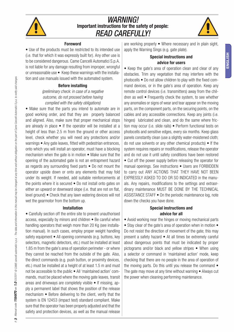
WARNING!Important instructions for the safety of people:
READ CAREFULLY!Foreword
• Use of the products must be restricted to its intended use
(i.e. that for which it was expressly built for). Any other use is
to be considered dangerous. Came Cancelli Automatici S.p.A.
is not liable for any damage resulting from improper, wrongful
or unreasonable use • Keep these warnings with the installa-
tion and use manuals issued with the automated system.
Before installing (preliminary check: in case of a negative outcome, do not proceed before having
complied with the safety obligations)• Make sure that the parts you intend to automate are in
good working order, and that they are properly balanced
and aligned. Also, make sure that proper mechanical stops
are already in place • If the operator will be installed at a
height of less than 2.5 m from the ground or other access
level, check whether you will need any protections and/or
warnings • Any gate leaves, fi tted with pedestrian entrances,
onto which you will install an operator, must have a blocking
mechanism when the gate is in motion • Make sure that the
opening of the automated gate is not an entrapment hazard
as regards any surrounding fi xed parts • Do not mount the
operator upside down or onto any elements that may fold
under its weight. If needed, add suitable reinforcements at
the points where it is secured • Do not install onto gates on
either an upward or downward slope (i.e. that are not on fl at,
level ground) • Check that any lawn watering devices will not
wet the gearmotor from the bottom up.
Installation• Carefully section off the entire site to prevent unauthorised
access, especially by minors and children • Be careful when
handling operators that weigh more than 20 Kg (see installa-
tion manual). In such cases, employ proper weight handling
safety equipment • All opening commands (e.g. buttons, key
selectors, magnetic detectors, etc.) must be installed at least
1.85 m from the gate’s area of operation perimeter - or where
they cannot be reached from the outside of the gate. Also,
the direct commands (e.g. push button, or proximity devices,
etc.) must be installed at a height of at least 1.5 m and must
not be accessible to the public • All ‘maintained action’ com-
mands, must be placed where the moving gate leaves, transit
areas and driveways are completely visible • If missing, ap-
ply a permanent label that shows the position of the release
mechanism • Before delivering to the client, verify that the
system is EN 12453 (impact test) standard compliant. Make
sure that the operator has been properly adjusted and that the
safety and protection devices, as well as the manual release
are working properly • Where necessary and in plain sight,
apply the Warning Sings (e.g. gate plate).
Special instructions and advice for users
• Keep the gate’s area of operation clean and clear of any
obstacles. Trim any vegetation that may interfere with the
photocells • Do not allow children to play with the fi xed com-
mand devices, or in the gate’s area of operation. Keep any
remote control devices (i.e. transmitters) away from the chil-
dren as well • Frequently check the system, to see whether
any anomalies or signs of wear and tear appear on the moving
parts, on the component parts, on the securing points, on the
cables and any accessible connections. Keep any joints (i.e.
hinges) lubricated and clean, and do the same where fric-
tion may occur (i.e. slide rails) • Perform functional tests on
photocells and sensitive edges, every six months. Keep glass
panels constantly clean (use a slightly water-moistened cloth;
do not use solvents or any other chemical products) • If the
system requires repairs or modifi cations, release the operator
and do not use it until safety conditions have been restored
• Cut off the power supply before releasing the operator for
manual openings. See instructions • Users are FORBIDDEN
to carry out ANY ACTIONS THAT THEY HAVE NOT BEEN
EXPRESSLY ASKED TO DO OR SO INDICATED in the manu-
als. Any repairs, modifi cations to the settings and extraor-
dinary maintenance MUST BE DONE BY THE TECHNICAL
ASSISTANCE STAFF • On the periodic maintenance log, note
down the checks you have done.
Special instructions and advice for all
• Avoid working near the hinges or moving mechanical parts
• Stay clear of the gate’s area of operation when in motion •
Do not resist the direction of movement of the gate; this may
present a safety hazard • At all times be extremely careful
about dangerous points that must be indicated by proper
pictograms and/or black and yellow stripes • When using
a selector or command in ‘maintained action’ mode, keep
checking that there are no people in the area of operation of
the moving parts. Do this until you release the command •
The gate may move at any time without warning • Always cut
the power when cleaning performing maintenance.
P. 44
- M
anual
cod
e: 1
19
AV
70
119
AV
70
ver
. 1
.01
.0 0
3/2
011
© C
AM
E ca
nce
lli a
utom
atic
i s.p
.a.
- Th
e dat
a an
d in
form
atio
n in
this
man
ual
may
be
chan
ged
at
any
time
and
with
out
oblig
atio
n on
the
par
t of
Cam
e C
ance
lli A
utom
atic
i S.p
.a.
to n
otify
sai
d ch
anges
.
EN
GLIS
H
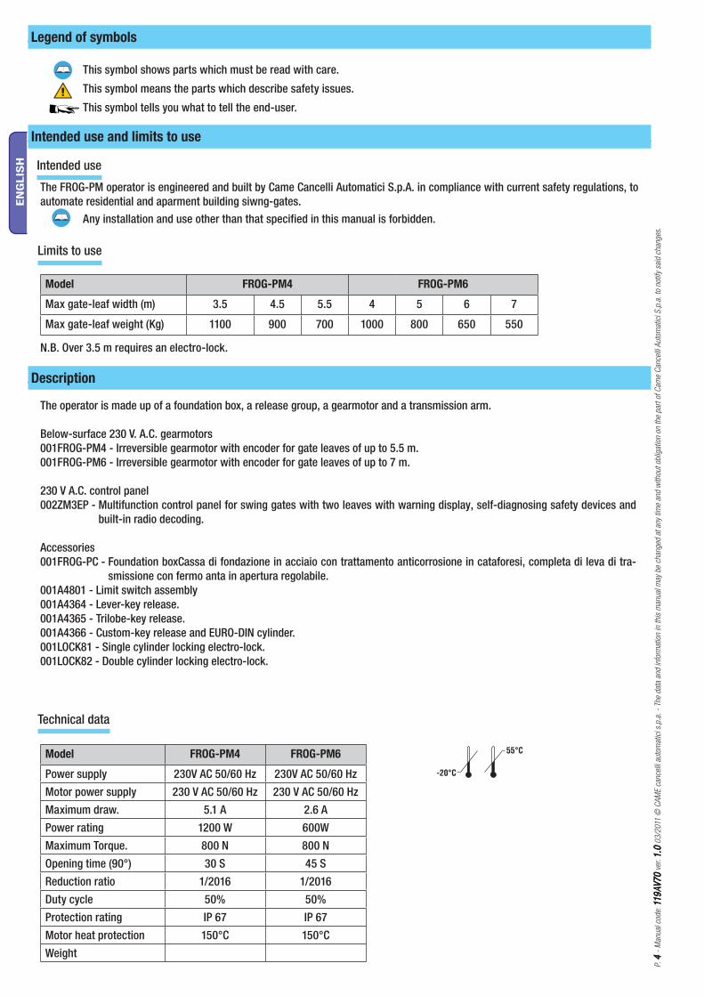
Legend of symbols
Intended use
Description
Intended use and limits to use
Technical data
Limits to use
This symbol shows parts which must be read with care.
This symbol means the parts which describe safety issues.
This symbol tells you what to tell the end-user.
The FROG-PM operator is engineered and built by Came Cancelli Automatici S.p.A. in compliance with current safety regulations, to automate residential and aparment building siwng-gates. Any installation and use other than that specified in this manual is forbidden.
N.B. Over 3.5 m requires an electro-lock.
Model FROG-PM4 FROG-PM6
Max gate-leaf width (m) 3.5 4.5 5.5 4 5 6 7
Max gate-leaf weight (Kg) 1100 900 700 1000 800 650 550
Model FROG-PM4 FROG-PM6
Power supply 230V AC 50/60 Hz 230V AC 50/60 Hz
Motor power supply 230 V AC 50/60 Hz 230 V AC 50/60 Hz
Maximum draw. 5.1 A 2.6 A
Power rating 1200 W 600W
Maximum Torque. 800 N 800 N
Opening time (90°) 30 S 45 S
Reduction ratio 1/2016 1/2016
Duty cycle 50% 50%
Protection rating IP 67 IP 67
Motor heat protection 150°C 150°C
Weight
The operator is made up of a foundation box, a release group, a gearmotor and a transmission arm.
Below-surface 230 V. A.C. gearmotors001FROG-PM4 - Irreversible gearmotor with encoder for gate leaves of up to 5.5 m.001FROG-PM6 - Irreversible gearmotor with encoder for gate leaves of up to 7 m.
230 V A.C. control panel002ZM3EP - Multifunction control panel for swing gates with two leaves with warning display, self-diagnosing safety devices and
built-in radio decoding.
Accessories001FROG-PC - Foundation boxCassa di fondazione in acciaio con trattamento anticorrosione in cataforesi, completa di leva di tra-
smissione con fermo anta in apertura regolabile.001A4801 - Limit switch assembly001A4364 - Lever-key release.001A4365 - Trilobe-key release.001A4366 - Custom-key release and EURO-DIN cylinder.001LOCK81 - Single cylinder locking electro-lock.001LOCK82 - Double cylinder locking electro-lock.
586
426
358
58
644
416
82
7
3
4
1
6
5
9
P. 55
- M
anual
cod
e: 1
19
AV
70
119
AV
70
ver
. 1
.01
.0 0
3/2
011
© C
AM
E ca
nce
lli a
utom
atic
i s.p
.a.
- Th
e dat
a an
d in
form
atio
n in
this
man
ual
may
be
chan
ged
at
any
time
and
with
out
oblig
atio
n on
the
par
t of
Cam
e C
ance
lli A
utom
atic
i S.p
.a.
to n
otify
sai
d ch
anges
.
EN
GLIS
H
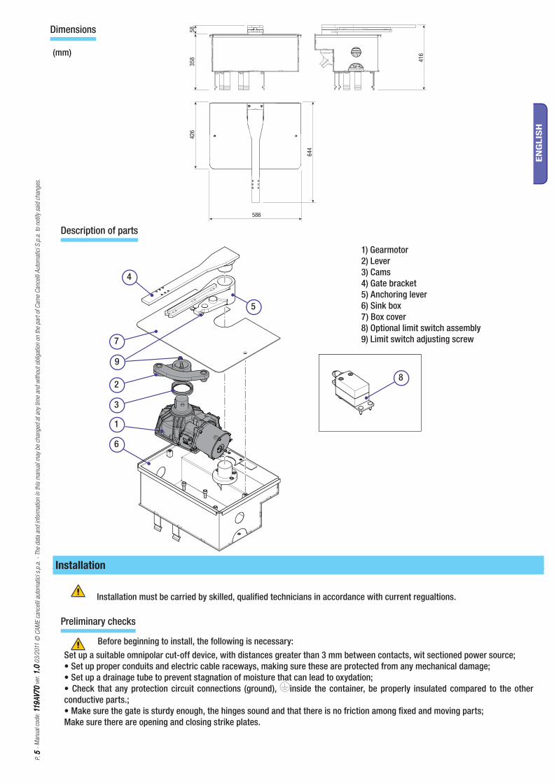
Dimensions
(mm)
Description of parts
1) Gearmotor2) Lever3) Cams4) Gate bracket5) Anchoring lever6) Sink box7) Box cover8) Optional limit switch assembly9) Limit switch adjusting screw
Installation
Preliminary checks
Before beginning to install, the following is necessary:Set up a suitable omnipolar cut-off device, with distances greater than 3 mm between contacts, wit sectioned power source;• Set up proper conduits and electric cable raceways, making sure these are protected from any mechanical damage;• Set up a drainage tube to prevent stagnation of moisture that can lead to oxydation;• Check that any protection circuit connections (ground), inside the container, be properly insulated compared to the other conductive parts.;• Make sure the gate is sturdy enough, the hinges sound and that there is no friction among fixed and moving parts;Make sure there are opening and closing strike plates.
Installation must be carried by skilled, qualified technicians in accordance with current regualtions.
5
2
8
8
7
9 10
6
14
4
1111
3
11
12
12
P. 66
- M
anual
cod
e: 1
19
AV
70
119
AV
70
ver
. 1
.01
.0 0
3/2
011
© C
AM
E ca
nce
lli a
utom
atic
i s.p
.a.
- Th
e dat
a an
d in
form
atio
n in
this
man
ual
may
be
chan
ged
at
any
time
and
with
out
oblig
atio
n on
the
par
t of
Cam
e C
ance
lli A
utom
atic
i S.p
.a.
to n
otify
sai
d ch
anges
.
EN
GLIS
H
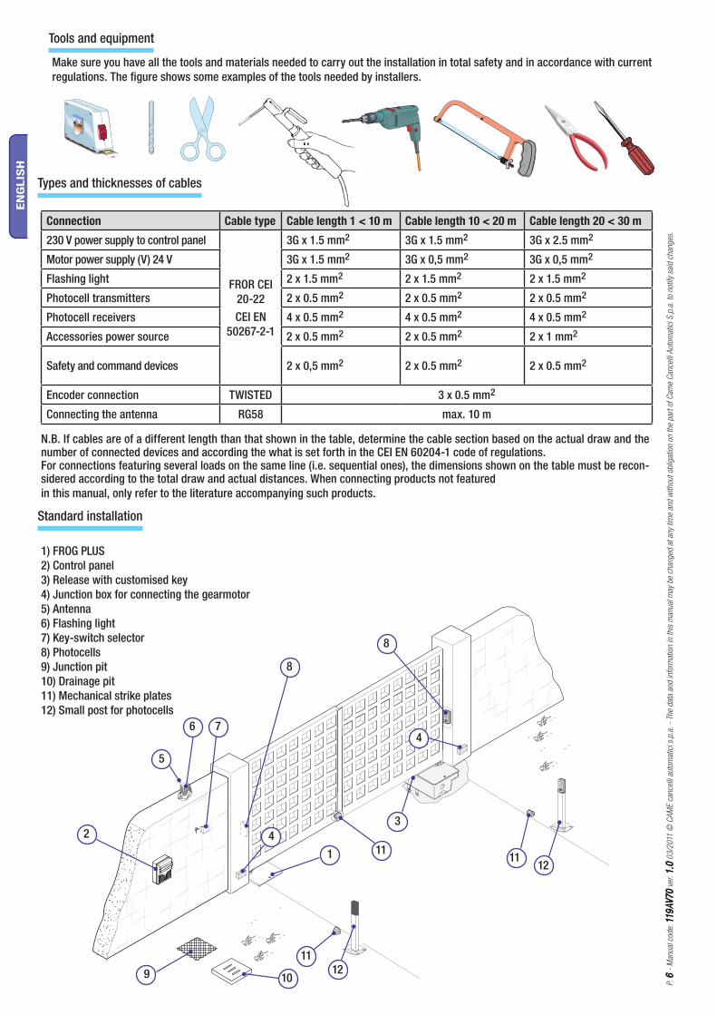
Types and thicknesses of cables
Connection Cable type Cable length 1 < 10 m Cable length 10 < 20 m Cable length 20 < 30 m
230 V power supply to control panel
FROR CEI 20-22 CEI EN
50267-2-1
3G x 1.5 mm2 3G x 1.5 mm2 3G x 2.5 mm2
Motor power supply (V) 24 V 3G x 1.5 mm2 3G x 0,5 mm2 3G x 0,5 mm2
Flashing light 2 x 1.5 mm2 2 x 1.5 mm2 2 x 1.5 mm2
Photocell transmitters 2 x 0.5 mm2 2 x 0.5 mm2 2 x 0.5 mm2
Photocell receivers 4 x 0.5 mm2 4 x 0.5 mm2 4 x 0.5 mm2
Accessories power source 2 x 0.5 mm2 2 x 0.5 mm2 2 x 1 mm2
Safety and command devices 2 x 0,5 mm2 2 x 0.5 mm2 2 x 0.5 mm2
Encoder connection TWISTED 3 x 0.5 mm2
Connecting the antenna RG58 max. 10 m
N.B. If cables are of a different length than that shown in the table, determine the cable section based on the actual draw and the number of connected devices and according the what is set forth in the CEI EN 60204-1 code of regulations.For connections featuring several loads on the same line (i.e. sequential ones), the dimensions shown on the table must be recon-sidered according to the total draw and actual distances. When connecting products not featured in this manual, only refer to the literature accompanying such products.
1) FROG PLUS2) Control panel3) Release with customised key4) Junction box for connecting the gearmotor5) Antenna6) Flashing light7) Key-switch selector8) Photocells9) Junction pit10) Drainage pit11) Mechanical strike plates12) Small post for photocells
Standard installation
Tools and equipment
Make sure you have all the tools and materials needed to carry out the installation in total safety and in accordance with current regulations. The figure shows some examples of the tools needed by installers.
500
650
500
94 mm
24h
P. 77
- M
anual
cod
e: 1
19
AV
70
119
AV
70
ver
. 1
.01
.0 0
3/2
011
© C
AM
E ca
nce
lli a
utom
atic
i s.p
.a.
- Th
e dat
a an
d in
form
atio
n in
this
man
ual
may
be
chan
ged
at
any
time
and
with
out
oblig
atio
n on
the
par
t of
Cam
e C
ance
lli A
utom
atic
i S.p
.a.
to n
otify
sai
d ch
anges
.
EN
GLIS
H
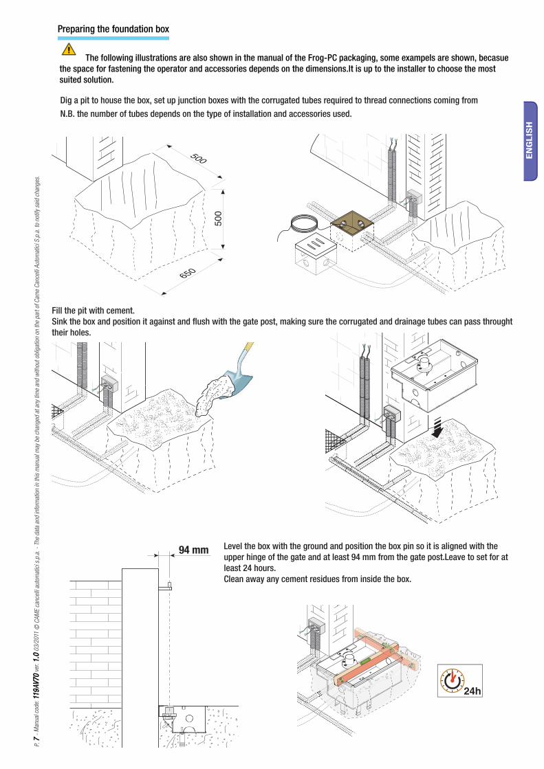
Preparing the foundation box
The following illustrations are also shown in the manual of the Frog-PC packaging, some exampels are shown, becasue the space for fastening the operator and accessories depends on the dimensions.It is up to the installer to choose the most suited solution.
Dig a pit to house the box, set up junction boxes with the corrugated tubes required to thread connections coming from N.B. the number of tubes depends on the type of installation and accessories used.
Fill the pit with cement.Sink the box and position it against and fl ush with the gate post, making sure the corrugated and drainage tubes can pass throught their holes.
Level the box with the ground and position the box pin so it is aligned with the upper hinge of the gate and at least 94 mm from the gate post.Leave to set for at least 24 hours.Clean away any cement residues from inside the box.
P. 88
- M
anual
cod
e: 1
19
AV
70
119
AV
70
ver
. 1
.01
.0 0
3/2
011
© C
AM
E ca
nce
lli a
utom
atic
i s.p
.a.
- Th
e dat
a an
d in
form
atio
n in
this
man
ual
may
be
chan
ged
at
any
time
and
with
out
oblig
atio
n on
the
par
t of
Cam
e C
ance
lli A
utom
atic
i S.p
.a.
to n
otify
sai
d ch
anges
.
EN
GLIS
H
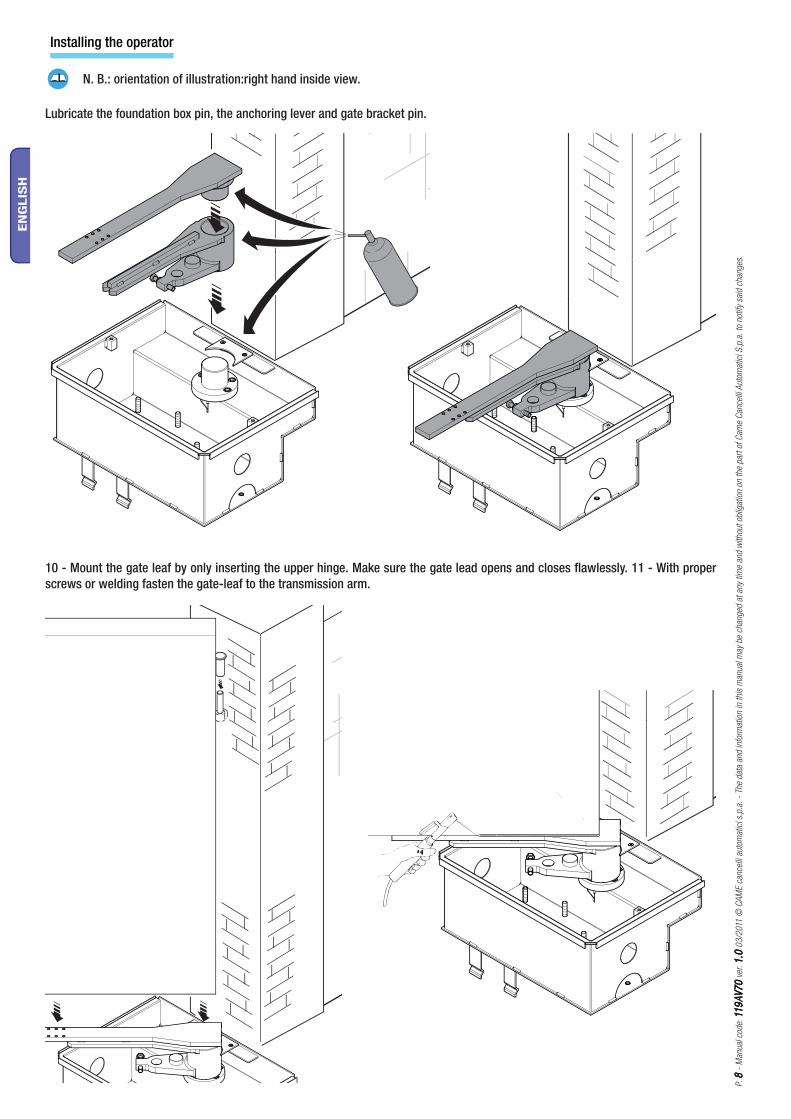
Installing the operator
Lubricate the foundation box pin, the anchoring lever and gate bracket pin.
N. B.: orientation of illustration:right hand inside view.
10 - Mount the gate leaf by only inserting the upper hinge. Make sure the gate lead opens and closes fl awlessly. 11 - With proper screws or welding fasten the gate-leaf to the transmission arm.
P. 99
- M
anual
cod
e: 1
19
AV
70
119
AV
70
ver
. 1
.01
.0 0
3/2
011
© C
AM
E ca
nce
lli a
utom
atic
i s.p
.a.
- Th
e dat
a an
d in
form
atio
n in
this
man
ual
may
be
chan
ged
at
any
time
and
with
out
oblig
atio
n on
the
par
t of
Cam
e C
ance
lli A
utom
atic
i S.p
.a.
to n
otify
sai
d ch
anges
.
EN
GLIS
H
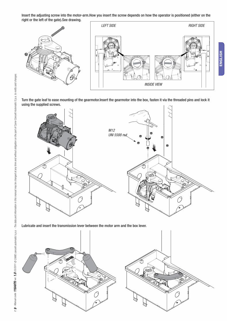
Turn the gate leaf to ease mounting of the gearmotor.Insert the gearmotor into the box, fasten it via the threaded pins and lock it using the supplied screws.
Insert the adjusting screw into the motor-arm.How you insert the screw depends on how the operator is positioned (either on the right or the left of the gate).See drawing.
M12UNI 5588 nut
Lubricate and insert the transmission lever between the motor arm and the box lever.
INSIDE VIEW
RIGHT SIDELEFT SIDE
1
5
2
3
4
4
U V W X Y E E+ - E+ -E3
P. 1
01
0 -
Man
ual
cod
e: 1
19
AV
70
119
AV
70
ver
. 1
.01
.0 0
3/2
011
© C
AM
E ca
nce
lli a
utom
atic
i s.p
.a.
- Th
e dat
a an
d in
form
atio
n in
this
man
ual
may
be
chan
ged
at
any
time
and
with
out
oblig
atio
n on
the
par
t of
Cam
e C
ance
lli A
utom
atic
i S.p
.a.
to n
otify
sai
d ch
anges
.
EN
GLIS
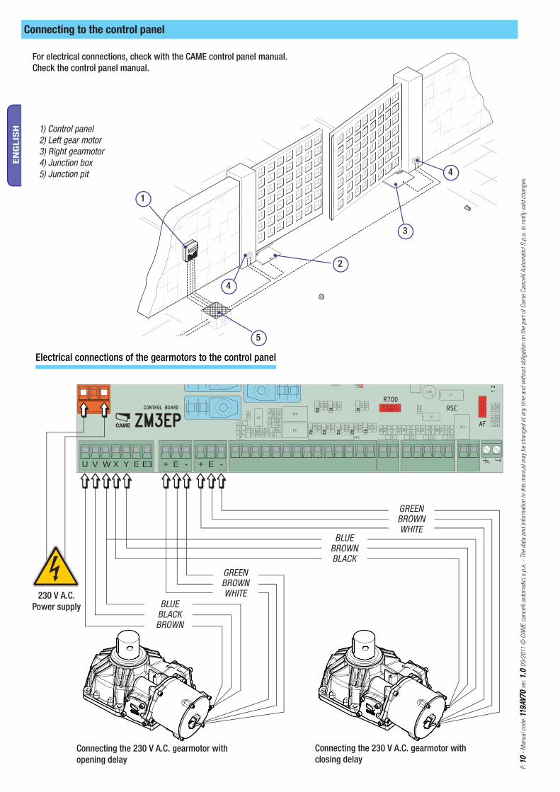
H 1) Control panel2) Left gear motor3) Right gearmotor4) Junction box5) Junction pit
Connecting the 230 V A.C. gearmotor with opening delay
Connecting the 230 V A.C. gearmotor with closing delay
230 V A.C. Power supply BLUE
BLACKBROWN
BLUEBROWNBLACK
GREENBROWNWHITE
Electrical connections of the gearmotors to the control panel
Connecting to the control panel
For electrical connections, check with the CAME control panel manual.Check the control panel manual.
GREENBROWNWHITE
3
12
123
P. 1
111 -
Man
ual
cod
e: 1
19
AV
70
119
AV
70
ver
. 1
.01
.0 0
3/2
011
© C
AM
E ca
nce
lli a
utom
atic
i s.p
.a.
- Th
e dat
a an
d in
form
atio
n in
this
man
ual
may
be
chan
ged
at
any
time
and
with
out
oblig
atio
n on
the
par
t of
Cam
e C
ance
lli A
utom
atic
i S.p
.a.
to n
otify
sai
d ch
anges
.
EN
GLIS
H
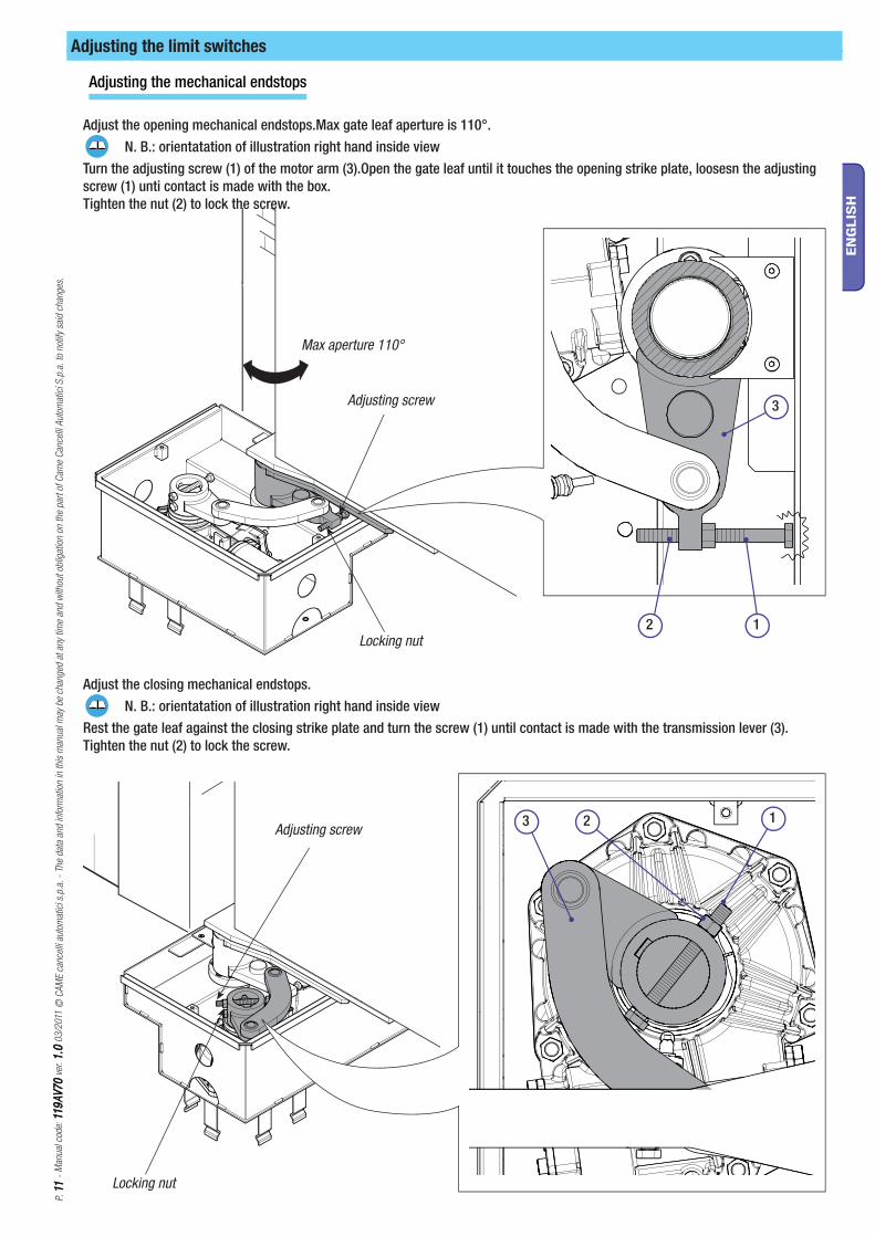
Adjusting the limit switches
Adjusting the mechanical endstops
Adjust the opening mechanical endstops.Max gate leaf aperture is 110°. N. B.: orientatation of illustration right hand inside viewTurn the adjusting screw (1) of the motor arm (3).Open the gate leaf until it touches the opening strike plate, loosesn the adjusting screw (1) unti contact is made with the box.Tighten the nut (2) to lock the screw.
Adjust the closing mechanical endstops. N. B.: orientatation of illustration right hand inside viewRest the gate leaf against the closing strike plate and turn the screw (1) until contact is made with the transmission lever (3).Tighten the nut (2) to lock the screw.
Adjusting screw
Max aperture 110°
Locking nut
Adjusting screw
Locking nut
A4366
A4365
A4364
P. 1
21
2 -
Man
ual
cod
e: 1
19
AV
70
119
AV
70
ver
. 1
.01
.0 0
3/2
011
© C
AM
E ca
nce
lli a
utom
atic
i s.p
.a.
- Th
e dat
a an
d in
form
atio
n in
this
man
ual
may
be
chan
ged
at
any
time
and
with
out
oblig
atio
n on
the
par
t of
Cam
e C
ance
lli A
utom
atic
i S.p
.a.
to n
otify
sai
d ch
anges
.
EN
GLIS
H
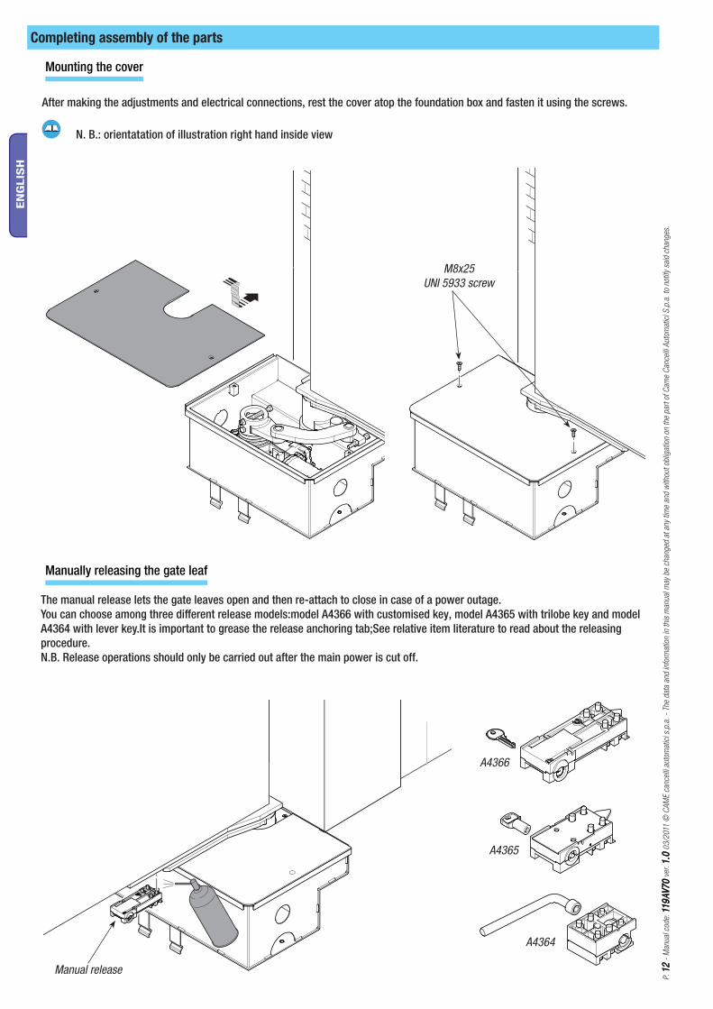
Mounting the cover
Manually releasing the gate leaf
After making the adjustments and electrical connections, rest the cover atop the foundation box and fasten it using the screws.
N. B.: orientatation of illustration right hand inside view
M8x25UNI 5933 screw
The manual release lets the gate leaves open and then re-attach to close in case of a power outage.You can choose among three diff erent release models:model A4366 with customised key, model A4365 with trilobe key and model A4364 with lever key.It is important to grease the release anchoring tab;See relative item literature to read about the releasing procedure.N.B. Release operations should only be carried out after the main power is cut off.
Manual release
Completing assembly of the parts
P. 1
31
3 -
Man
ual
cod
e: 1
19
AV
70
119
AV
70
ver
. 1
.01
.0 0
3/2
011
© C
AM
E ca
nce
lli a
utom
atic
i s.p
.a.
- Th
e dat
a an
d in
form
atio
n in
this
man
ual
may
be
chan
ged
at
any
time
and
with
out
oblig
atio
n on
the
par
t of
Cam
e C
ance
lli A
utom
atic
i S.p
.a.
to n
otify
sai
d ch
anges
.
EN
GLIS
H
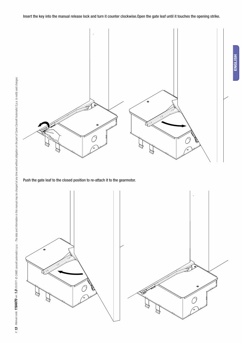
Insert the key into the manual release lock and turn it counter clockwise.Open the gate leaf until it touches the opening strike.
Push the gate leaf to the closed position to re-attach it to the gearmotor.
P. 1
414
- M
anual
cod
e: 1
19
AV
70
119
AV
70
ver
. 1
.01
.0 0
3/2
011
© C
AM
E ca
nce
lli a
utom
atic
i s.p
.a.
- Th
e dat
a an
d in
form
atio
n in
this
man
ual
may
be
chan
ged
at
any
time
and
with
out
oblig
atio
n on
the
par
t of
Cam
e C
ance
lli A
utom
atic
i S.p
.a.
to n
otify
sai
d ch
anges
.
EN
GLIS
H
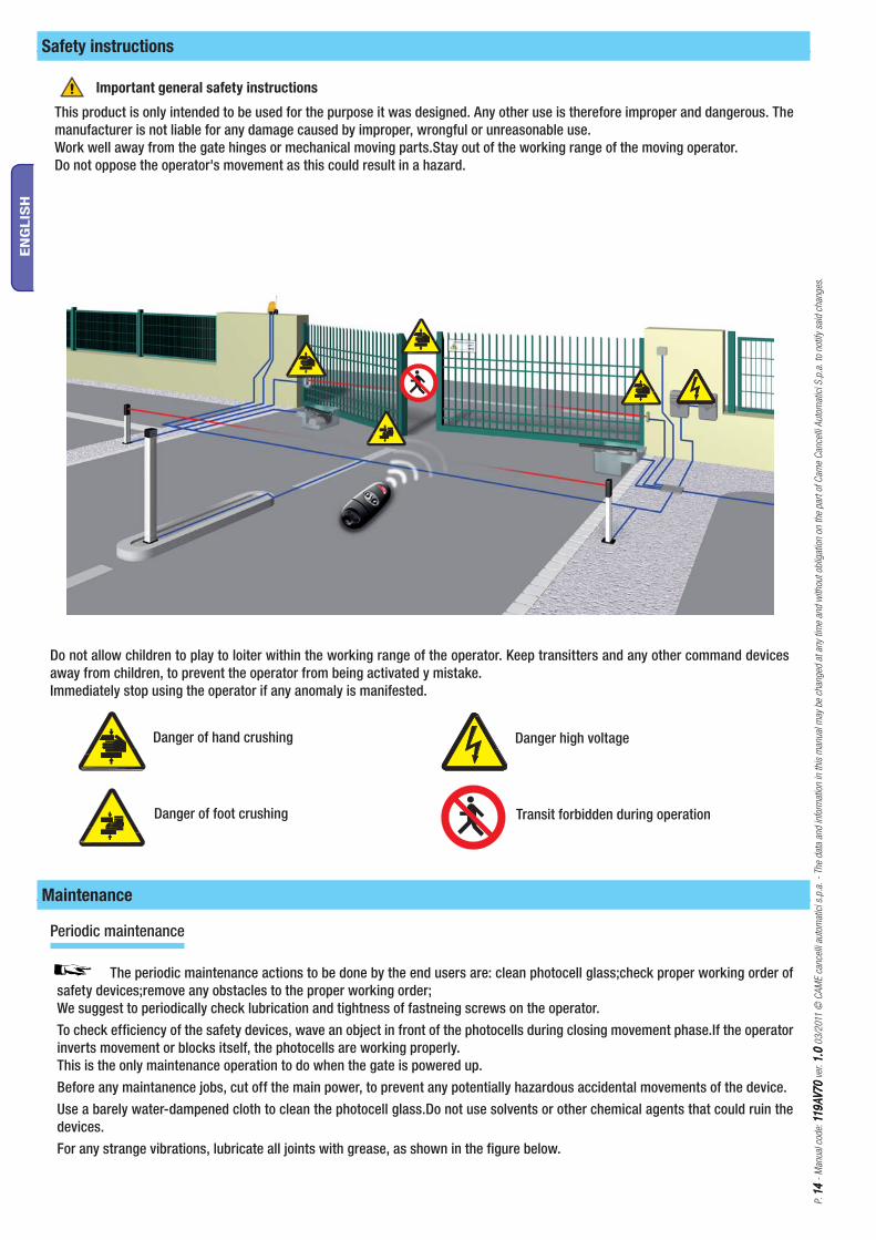
This product is only intended to be used for the purpose it was designed. Any other use is therefore improper and dangerous. The manufacturer is not liable for any damage caused by improper, wrongful or unreasonable use.Work well away from the gate hinges or mechanical moving parts.Stay out of the working range of the moving operator.Do not oppose the operator's movement as this could result in a hazard.
Important general safety instructions
Safety instructions
Do not allow children to play to loiter within the working range of the operator. Keep transitters and any other command devices away from children, to prevent the operator from being activated y mistake.Immediately stop using the operator if any anomaly is manifested.
Danger of hand crushing
Danger of foot crushing
Danger high voltage
Transit forbidden during operation
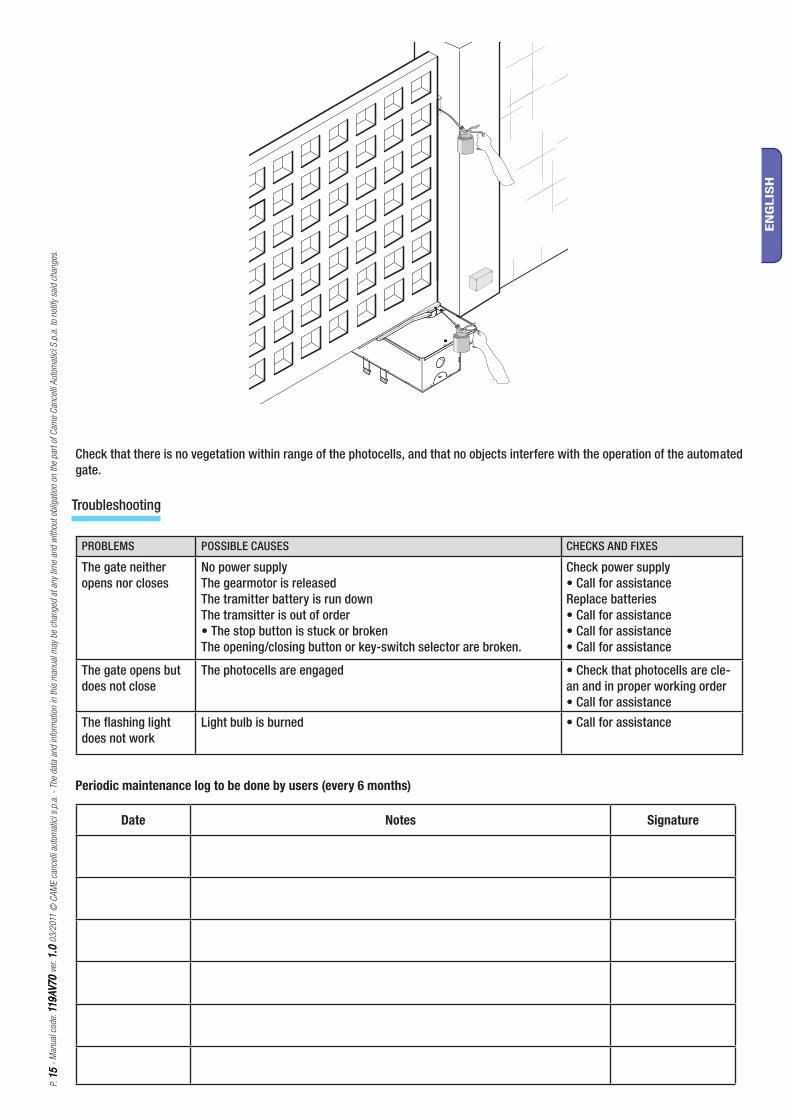
The periodic maintenance actions to be done by the end users are: clean photocell glass;check proper working order of safety devices;remove any obstacles to the proper working order;We suggest to periodically check lubrication and tightness of fastneing screws on the operator.To check efficiency of the safety devices, wave an object in front of the photocells during closing movement phase.If the operator inverts movement or blocks itself, the photocells are working properly.This is the only maintenance operation to do when the gate is powered up.Before any maintanence jobs, cut off the main power, to prevent any potentially hazardous accidental movements of the device.Use a barely water-dampened cloth to clean the photocell glass.Do not use solvents or other chemical agents that could ruin the devices.For any strange vibrations, lubricate all joints with grease, as shown in the figure below.
Maintenance
Periodic maintenance
P. 1
51
5 -
Man
ual
cod
e: 1
19
AV
70
119
AV
70
ver
. 1
.01
.0 0
3/2
011
© C
AM
E ca
nce
lli a
utom
atic
i s.p
.a.
- Th
e dat
a an
d in
form
atio
n in
this
man
ual
may
be
chan
ged
at
any
time
and
with
out
oblig
atio
n on
the
par
t of
Cam
e C
ance
lli A
utom
atic
i S.p
.a.
to n
otify
sai
d ch
anges
.
EN
GLIS
H
Check that there is no vegetation within range of the photocells, and that no objects interfere with the operation of the automated gate.
PROBLEMS POSSIBLE CAUSES CHECKS AND FIXES
The gate neither opens nor closes
No power supplyThe gearmotor is releasedThe tramitter battery is run downThe tramsitter is out of order• The stop button is stuck or brokenThe opening/closing button or key-switch selector are broken.
Check power supply• Call for assistanceReplace batteries• Call for assistance• Call for assistance• Call for assistance
The gate opens but does not close
The photocells are engaged • Check that photocells are cle-an and in proper working order• Call for assistance
The flashing light does not work
Light bulb is burned • Call for assistance
Troubleshooting
Date Notes Signature
Periodic maintenance log to be done by users (every 6 months)
P. 1
61
6 -
Man
ual
cod
e: 1
19
AV
70
119
AV
70
ver
. 1
.01
.0 0
3/2
011
© C
AM
E ca
nce
lli a
utom
atic
i s.p
.a.
- Th
e dat
a an
d in
form
atio
n in
this
man
ual
may
be
chan
ged
at
any
time
and
with
out
oblig
atio
n on
the
par
t of
Cam
e C
ance
lli A
utom
atic
i S.p
.a.
to n
otify
sai
d ch
anges
.
EN
GLIS
H
On its premises, CAME Cancelli Automatici S.p.A. implements a certified Environmental Management System in com-pliance with the UNI EN ISO 14001 standard to ensure environmental protection.Please help us to safeguard the environment. At CAME we believe this to be one of the fundamentals in its market operations and development strategies. Just follow these short disposal instructions:
DISPOSING OF THE PACKAGINGThe components of the packaging (i.e. cardboard, plastic, etc.) are solid urban waste and may be disposed of without much trouble, simply by separating them for recycling.Before proceeding it is always a good idea to check your local legislation on the matter.DO NOT DISPOSE OF IN NATURE!
PRODUCT DISPOSALOur products are made up of various materials. Most of these (aluminium, plastic, iron, electric cables) are solid urban waste. These can be disposed of at local solid waste management dumps or recycling plants. Other components (i.e. electronic cards, remote control batteries, etc. ) may contain hazardous substances. These must therefore be handed over the specially authorised disposal firms.Before proceeding it is always a good idea to check your local legislation on the matter.DO NOT DISPOSE OF IN NATURE!
Installer's stamp Product name
Date of job
Technician's signature
Customer's signature
Job carried out _______________________________________________________________________________________________________________________________________________________________________________________________________________________________________________________________________________________
The following table is used to log extraordinary maintenance, repair and improvement jobs done by the specialised exter-nal firms. N.B. All extraordinary maintenance jobs must be carried out by skilled technicians.
Installer's stamp Product name
Date of job
Technician's signature
Customer's signature
Job carried out _______________________________________________________________________________________________________________________________________________________________________________________________________________________________________________________________________________________
Extraordinary maintenance log
Dismantling and disposal
Extraordinary maintenance
P. 1
717 -
Man
ual
cod
e: 1
19
AV
70
119
AV
70
ver
. 1
.01
.0 0
3/2
011
© C
AM
E ca
nce
lli a
utom
atic
i s.p
.a.
- Th
e dat
a an
d in
form
atio
n in
this
man
ual
may
be
chan
ged
at
any
time
and
with
out
oblig
atio
n on
the
par
t of
Cam
e C
ance
lli A
utom
atic
i S.p
.a.
to n
otify
sai
d ch
anges
.
EN
GLIS
H
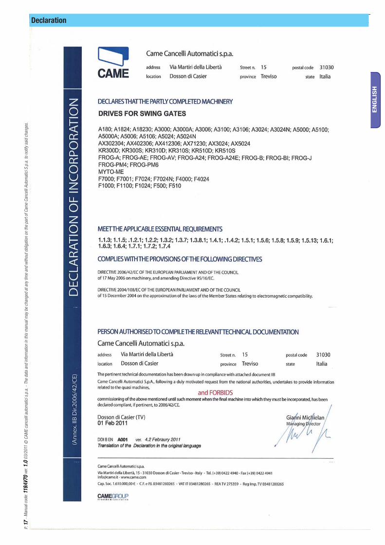
Declaration
CAMECAME FranceFrance S.a. S.a. FRANCE7, Rue Des HarasZ.i. Des Hautes Patures92737 Nanterre CedexNanterre Cedex
(+33) 0 825 825 874 (+33) 1 46 13 05 00
GERMANY CAME Gmbh Seefeld CAME Gmbh SeefeldAkazienstrasse, 9
16356 Seefeld Seefeld Bei Berlin (+49) 33 3988390
(+49) 33 39883985
CAME Automatismes S.a. CAME Automatismes S.a. FRANCE3, Rue Odette Jasse13015 MarseilleMarseille
(+33) 0 825 825 874 (+33) 4 91 60 69 05
U.A.E. CAME Gulf Fze CAME Gulf FzeOffi ce No: S10122a2o210
P.O. Box 262853 Jebel Ali Free Zone - Dubai Dubai
(+971) 4 8860046 (+971) 4 8860048
CAME Automatismos S.a. CAME Automatismos S.a. SPAINC/juan De Mariana, N. 17-local28045 Madrid Madrid
(+34) 91 52 85 009 (+34) 91 46 85 442
RUSSIA CAME Rus CAME RusUmc Rus LlcUmc Rus Llc
Ul. Otradnaya D. 2b, Str. 2, offi ce 219 127273, MoscowMoscow
(+7) 495 739 00 69 (+7) 495 739 00 69 (ext. 226)
CAME United Kingdom Ltd. CAME United Kingdom Ltd. GREAT BRITAINUnit 3 Orchard Business ParkTown Street, SandiacreNottingham Nottingham - Ng10 5bp
(+44) 115 9210430 (+44) 115 9210431
PORTUGAL CAME Portugal CAME Portugal Ucj Portugal Unipessoal LdaUcj Portugal Unipessoal Lda
Rua Liebig, nº 23 2830-141 BarreiroBarreiro
(+351) 21 207 39 67 (+351) 21 207 39 65
CAME Group Benelux S.a. CAME Group Benelux S.a. BELGIUMZoning Ouest 77860 Lessines Lessines
(+32) 68 333014 (+32) 68 338019
INDIA CAME India CAME India Automation Solutions Pvt. LtdAutomation Solutions Pvt. Ltd
A - 10, Green Park 110016 - New DelhiNew Delhi
(+91) 11 64640255/256 (+91) 2678 3510
CAME Americas Automation Llc CAME Americas Automation Llc U.S.A11345 NW 122nd St. MedleyMedley, FL 33178
(+1) 305 433 3307 (+1) 305 396 3331
ASIA CAME Asia Pacific CAME Asia Pacific 60 Alexandra Terrace #09-09
Block C, The ComTech118 502 SingaporeSingapore
(+65) 6275 8426 (+65) 6275 5451
CAME Gmbh CAME Gmbh GERMANYKornwestheimer Str. 3770825 Korntal Korntal Munchingen Bei Stuttgart
(+49) 71 5037830 (+49) 71 50378383
CAME Cancelli Automatici S.p.a. CAME Cancelli Automatici S.p.a. ITALYVia Martiri Della Libertà, 1531030 Dosson Di Casier Dosson Di Casier (Tv)
(+39) 0422 4940 (+39) 0422 4941
Informazioni Commerciali 800 848095
ITALY CAME Sud s.r.l.CAME Sud s.r.l.Via F. Imparato, 198
Centro Mercato 2, Lotto A/7 80146 Napoli Napoli
(+39) 081 7524455 (+39) 081 7529190
CAME Service Italia S.r.l. CAME Service Italia S.r.l. ITALYVia Della Pace, 2831030 Dosson Di Casier Dosson Di Casier (Tv)
(+39) 0422 383532 (+39) 0422 490044
Assistenza Tecnica 800 295830Assistenza Tecnica 800 295830
ITALY CAME Global Utilities s.r.l.CAME Global Utilities s.r.l.Via E. Fermi, 31
20060 GessateGessate (Mi) (+39) 02 95380366 (+39) 02 95380224
01_2011
www.came.com www.came.it
En
glish
En
glish
- M
anual
cod
e 11
9A
V7
011
9A
V7
0 v
er. 1
.01
.0 0
3/2
011
© C
AM
E ca
nce
lli a
utom
atic
i s.p
.a.
The
dat
a an
d in
form
atio
n in
this
man
ual
may
be
chan
ged
at
any
time
and
with
out
oblig
atio
n on
the
par
t of
Cam
e C
ance
lli A
utom
atic
i S.p
.a.
to n
otify
sai
d ch
anges
.