Frame Alteration Recommendations - Ram Body Builder · 2015 Chassis Cab Frame Alteration...
12
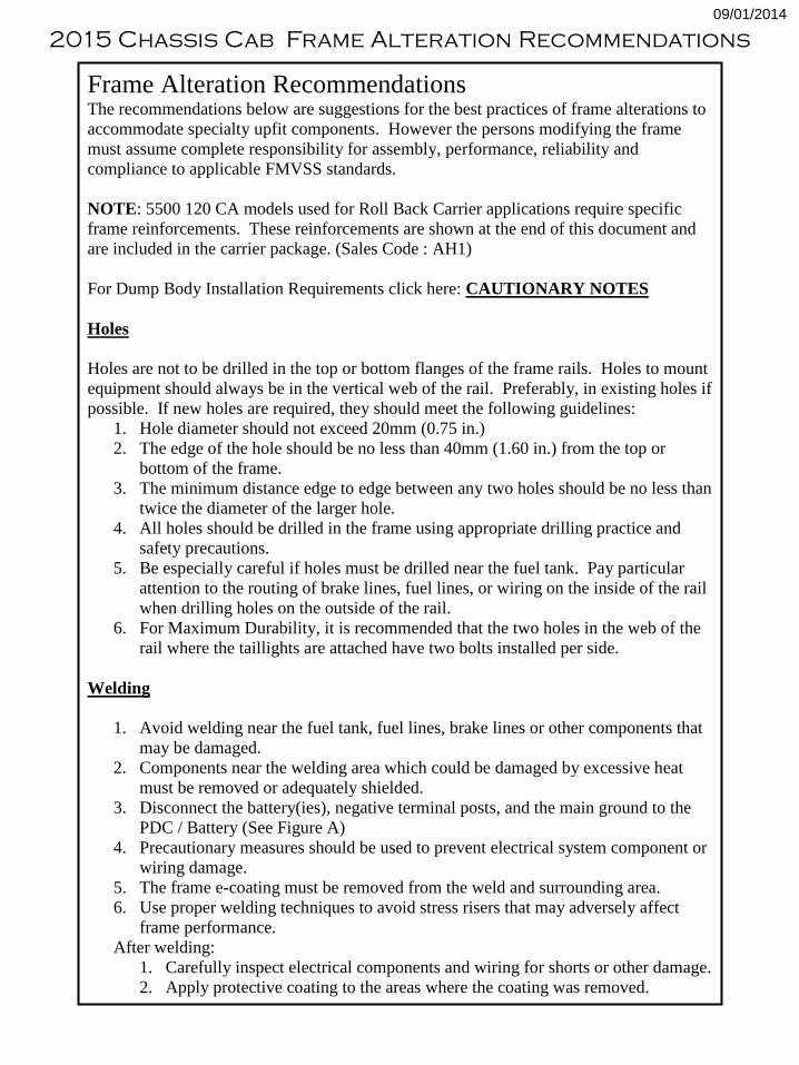
2015 Chassis Cab Frame Alteration Recommendations 09/01/2014 Frame Alteration Recommendations The recommendations below are suggestions for the best practices of frame alterations to accommodate specialty upfit components. However the persons modifying the frame must assume complete responsibility for assembly, performance, reliability and compliance to applicable FMVSS standards. NOTE: 5500 120 CA models used for Roll Back Carrier applications require specific frame reinforcements. These reinforcements are shown at the end of this document and are included in the carrier package. (Sales Code : AH1) For Dump Body Installation Requirements click here: CAUTIONARY NOTES Holes Holes are not to be drilled in the top or bottom flanges of the frame rails. Holes to mount equipment should always be in the vertical web of the rail. Preferably, in existing holes if possible. If new holes are required, they should meet the following guidelines: 1. Hole diameter should not exceed 20mm (0.75 in.) 2. The edge of the hole should be no less than 40mm (1.60 in.) from the top or bottom of the frame. 3. The minimum distance edge to edge between any two holes should be no less than twice the diameter of the larger hole. 4. All holes should be drilled in the frame using appropriate drilling practice and safety precautions. 5. Be especially careful if holes must be drilled near the fuel tank. Pay particular attention to the routing of brake lines, fuel lines, or wiring on the inside of the rail when drilling holes on the outside of the rail. 6. For Maximum Durability, it is recommended that the two holes in the web of the rail where the taillights are attached have two bolts installed per side. Welding 1. Avoid welding near the fuel tank, fuel lines, brake lines or other components that may be damaged. 2. Components near the welding area which could be damaged by excessive heat must be removed or adequately shielded. 3. Disconnect the battery(ies), negative terminal posts, and the main ground to the PDC / Battery (See Figure A) 4. Precautionary measures should be used to prevent electrical system component or wiring damage. 5. The frame e-coating must be removed from the weld and surrounding area. 6. Use proper welding techniques to avoid stress risers that may adversely affect frame performance. After welding: 1. Carefully inspect electrical components and wiring for shorts or other damage. 2. Apply protective coating to the areas where the coating was removed.
Transcript of Frame Alteration Recommendations - Ram Body Builder · 2015 Chassis Cab Frame Alteration...
2015 Chassis Cab Frame Alteration Recommendations
09/01/2014
Frame Alteration Recommendations The recommendations below are suggestions for the best practices of frame alterations to
accommodate specialty upfit components. However the persons modifying the frame
must assume complete responsibility for assembly, performance, reliability and
compliance to applicable FMVSS standards.
NOTE: 5500 120 CA models used for Roll Back Carrier applications require specific
frame reinforcements. These reinforcements are shown at the end of this document and
are included in the carrier package. (Sales Code : AH1)
For Dump Body Installation Requirements click here: CAUTIONARY NOTES
Holes
Holes are not to be drilled in the top or bottom flanges of the frame rails. Holes to mount
equipment should always be in the vertical web of the rail. Preferably, in existing holes if
possible. If new holes are required, they should meet the following guidelines:
1. Hole diameter should not exceed 20mm (0.75 in.)
2. The edge of the hole should be no less than 40mm (1.60 in.) from the top or
bottom of the frame.
3. The minimum distance edge to edge between any two holes should be no less than
twice the diameter of the larger hole.
4. All holes should be drilled in the frame using appropriate drilling practice and
safety precautions.
5. Be especially careful if holes must be drilled near the fuel tank. Pay particular
attention to the routing of brake lines, fuel lines, or wiring on the inside of the rail
when drilling holes on the outside of the rail.
6. For Maximum Durability, it is recommended that the two holes in the web of the
rail where the taillights are attached have two bolts installed per side.
Welding
1. Avoid welding near the fuel tank, fuel lines, brake lines or other components that
may be damaged.
2. Components near the welding area which could be damaged by excessive heat
must be removed or adequately shielded.
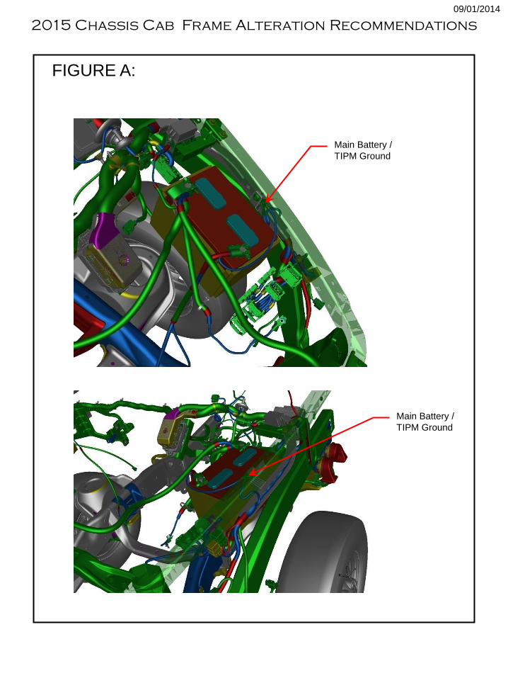
3. Disconnect the battery(ies), negative terminal posts, and the main ground to the
PDC / Battery (See Figure A)
4. Precautionary measures should be used to prevent electrical system component or
wiring damage.
5. The frame e-coating must be removed from the weld and surrounding area.
6. Use proper welding techniques to avoid stress risers that may adversely affect
frame performance.
After welding:
1. Carefully inspect electrical components and wiring for shorts or other damage.
2. Apply protective coating to the areas where the coating was removed.
Main Battery /
TIPM Ground
Main Battery /
TIPM Ground
FIGURE A:
2015 Chassis Cab Frame Alteration Recommendations
09/01/2014
Frame Length Alterations
If shortening the frame at the rear overhang:
1. Drill out the rivets that attach the rearmost crossmember to the rear of the frame.
2. Reinstall the crossmember in the forward mounting location. This location shares
the attachment holes for the rear spring rear hanger on the web of the rail and pre-
pierced holes on the flanges. If the cutoff dimension is longer than the minimum
dimension described above, use the crossmember as a template to drill additional
holes in the rear rails to allow for the attachment of the crossmember at the rear of
the frame.
3. If required, a second crossmember can be added using the second set of holes
located on the front of the rear spring front hanger. (See Figure B for part numbers)
4. The preferred method to cut the frame is with a saw or cutoff wheel. If a torch is
used any rivets within 4 inches must be replaced with equivalent size grade 8 (or
grade 10.9 metric) bolts and any existing bolts must be retorqued.
5. Areas of the frame that have now become exposed metal should be coated with a
corrosion protecting coating.
If lengthening the frame:
1. In preparation for welding, clean the e-coat from the frame surface with a wire
wheel or equivalent.
2. Use a mild (low carbon) steel material of comparable thickness to the rails.
3. Chamfer the two mating areas to be joined by welding.
4. If extending the rear of the frame, include a reinforcement that is welded to the
extension channel and extends forward far enough to allow bolting through the
rear crossmember lower rivet (requiring drilling out this rivet).
5. Disconnect the battery (ies negative terminal posts, and the main ground to the
TIPM/Battery (See Figure A).
6. Butt weld the frame and extension together on the top and side omitting welding
on the lower flange if extending the rear of the frame as above.
7. Grind smooth the outer surface of the vertical web of the rail. Clamp on a
reinforcement plate ¼” mild steel 4 “x12 “. If extending the rear of the frame,
drill two holes in the reinforcement through the upper shear plate hole and the
lower rear crossmember hole. ‘Mirror’ two more of these holes in the
reinforcement through the extension piece (See Figure C). Stitch weld the
reinforcement onto the rail and extension avoiding the corners. Install ½” bolts
with flange heads (or hardened washers) into the four holes.
8. Coat the frame with a corrosion protective coating. Reconnect the electrical
components.
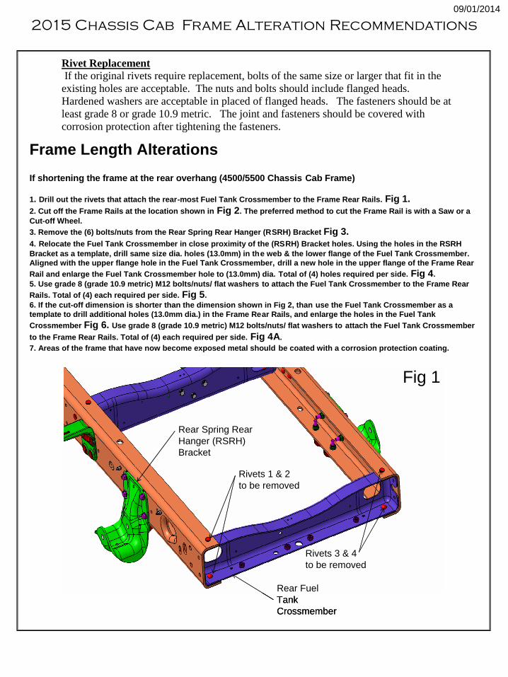
Rivet Replacement
If the original rivets require replacement, bolts of the same size or larger that fit in the
existing holes are acceptable. The nuts and bolts should include flanged heads.
Hardened washers are acceptable in placed of flanged heads. The fasteners should be at
least grade 8 or grade 10.9 metric. The joint and fasteners should be covered with
corrosion protection after tightening the fasteners.
Frame Length Alterations
If shortening the frame at the rear overhang (4500/5500 Chassis Cab Frame)
1. Drill out the rivets that attach the rear-most Fuel Tank Crossmember to the Frame Rear Rails. Fig 1.
2. Cut off the Frame Rails at the location shown in Fig 2. The preferred method to cut the Frame Rail is with a Saw or a
Cut-off Wheel.
3. Remove the (6) bolts/nuts from the Rear Spring Rear Hanger (RSRH) Bracket Fig 3.
4. Relocate the Fuel Tank Crossmember in close proximity of the (RSRH) Bracket holes. Using the holes in the RSRH
Bracket as a template, drill same size dia. holes (13.0mm) in the web & the lower flange of the Fuel Tank Crossmember.
Aligned with the upper flange hole in the Fuel Tank Crossmember, drill a new hole in the upper flange of the Frame Rear
Rail and enlarge the Fuel Tank Crossmember hole to (13.0mm) dia. Total of (4) holes required per side. Fig 4.
5. Use grade 8 (grade 10.9 metric) M12 bolts/nuts/ flat washers to attach the Fuel Tank Crossmember to the Frame Rear
Rails. Total of (4) each required per side. Fig 5.
6. If the cut-off dimension is shorter than the dimension shown in Fig 2, than use the Fuel Tank Crossmember as a
template to drill additional holes (13.0mm dia.) in the Frame Rear Rails, and enlarge the holes in the Fuel Tank
Crossmember Fig 6. Use grade 8 (grade 10.9 metric) M12 bolts/nuts/ flat washers to attach the Fuel Tank Crossmember
to the Frame Rear Rails. Total of (4) each required per side. Fig 4A.
7. Areas of the frame that have now become exposed metal should be coated with a corrosion protection coating.
Fig 1
Rear Fuel
Tank
Crossmember
Rivets 1 & 2
to be removed
Rivets 3 & 4
to be removed
Rear Spring Rear
Hanger (RSRH)
Bracket
Fig 1
Rear Fuel
Tank
Crossmember
Rivets 1 & 2
to be removed
Rivets 3 & 4
to be removed
Rear Spring Rear
Hanger (RSRH)
Bracket
2015 Chassis Cab Frame Alteration Recommendations
09/01/2014
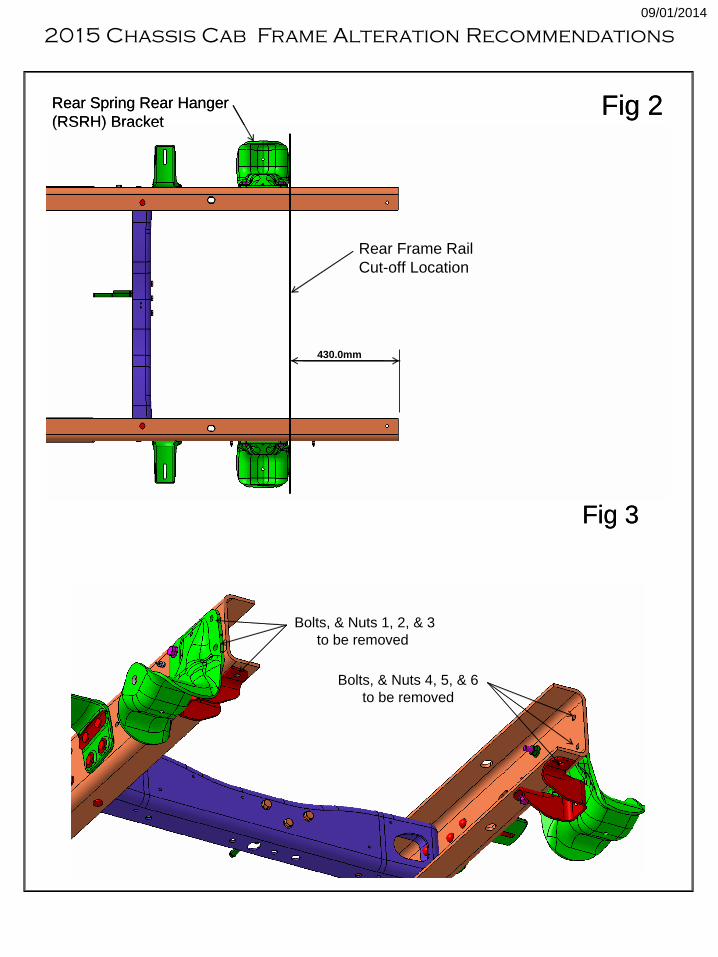
Fig 2Rear Spring Rear Hanger
(RSRH) Bracket
Rear Frame Rail
Cut-off Location
430.0mm
Fig 2Rear Spring Rear Hanger
(RSRH) Bracket
Rear Frame Rail
Cut-off Location
430.0mm
Bolts, & Nuts 1, 2, & 3
to be removed
Bolts, & Nuts 4, 5, & 6
to be removed
Fig 3
Bolts, & Nuts 1, 2, & 3
to be removed
Bolts, & Nuts 4, 5, & 6
to be removed
Fig 3
2015 Chassis Cab Frame Alteration Recommendations
09/01/2014
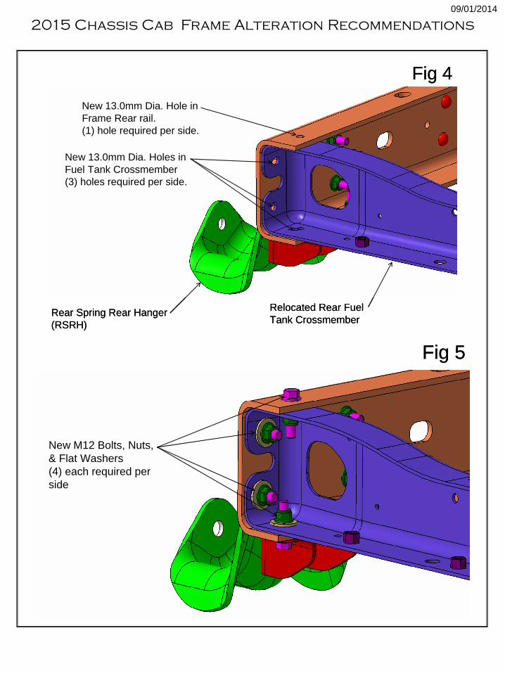
Fig 4
Relocated Rear Fuel
Tank CrossmemberRear Spring Rear Hanger
(RSRH)
New 13.0mm Dia. Holes in
Fuel Tank Crossmember
(3) holes required per side.
New 13.0mm Dia. Hole in
Frame Rear rail.
(1) hole required per side.
Fig 4
Relocated Rear Fuel
Tank CrossmemberRear Spring Rear Hanger
(RSRH)
New 13.0mm Dia. Holes in
Fuel Tank Crossmember
(3) holes required per side.
New 13.0mm Dia. Hole in
Frame Rear rail.
(1) hole required per side.
Fig 5
New M12 Bolts, Nuts,
& Flat Washers
(4) each required per
side
Fig 5
New M12 Bolts, Nuts,
& Flat Washers
(4) each required per
side
2015 Chassis Cab Frame Alteration Recommendations
09/01/2014
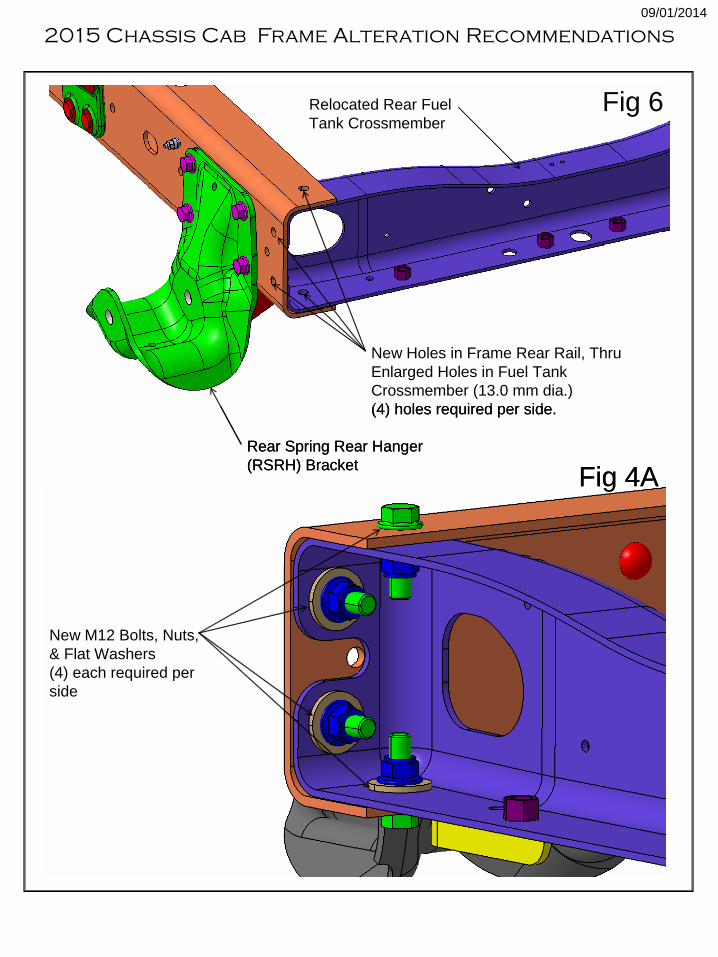
Fig 6
New Holes in Frame Rear Rail, Thru
Enlarged Holes in Fuel Tank
Crossmember (13.0 mm dia.)
(4) holes required per side.
Relocated Rear Fuel
Tank Crossmember
Rear Spring Rear Hanger
(RSRH) Bracket
Fig 6
New Holes in Frame Rear Rail, Thru
Enlarged Holes in Fuel Tank
Crossmember (13.0 mm dia.)
(4) holes required per side.
Relocated Rear Fuel
Tank Crossmember
Rear Spring Rear Hanger
(RSRH) Bracket
New M12 Bolts, Nuts,
& Flat Washers
(4) each required per
side
Fig 4A
New M12 Bolts, Nuts,
& Flat Washers
(4) each required per
side
Fig 4A
2015 Chassis Cab Frame Alteration Recommendations
09/01/2014
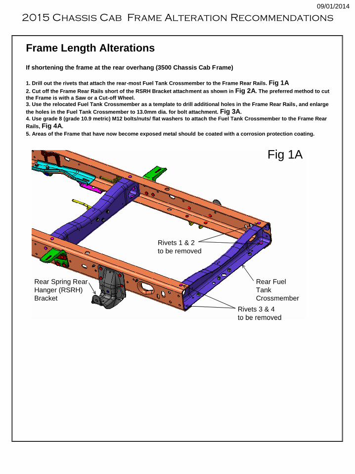
Frame Length Alterations
If shortening the frame at the rear overhang (3500 Chassis Cab Frame)
1. Drill out the rivets that attach the rear-most Fuel Tank Crossmember to the Frame Rear Rails. Fig 1A
2. Cut off the Frame Rear Rails short of the RSRH Bracket attachment as shown in Fig 2A. The preferred method to cut
the Frame is with a Saw or a Cut-off Wheel.
3. Use the relocated Fuel Tank Crossmember as a template to drill additional holes in the Frame Rear Rails, and enlarge
the holes in the Fuel Tank Crossmember to 13.0mm dia. for bolt attachment. Fig 3A.
4. Use grade 8 (grade 10.9 metric) M12 bolts/nuts/ flat washers to attach the Fuel Tank Crossmember to the Frame Rear
Rails, Fig 4A.
5. Areas of the Frame that have now become exposed metal should be coated with a corrosion protection coating.
Fig 1A
Rivets 1 & 2
to be removed
Rivets 3 & 4
to be removed
Rear Fuel
Tank
Crossmember
Rear Spring Rear
Hanger (RSRH)
Bracket
Fig 1A
Rivets 1 & 2
to be removed
Rivets 3 & 4
to be removed
Rear Fuel
Tank
Crossmember
Rear Spring Rear
Hanger (RSRH)
Bracket
2015 Chassis Cab Frame Alteration Recommendations
09/01/2014
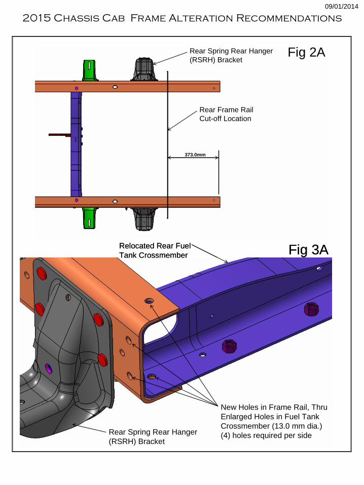
Rear Spring Rear Hanger
(RSRH) Bracket
Rear Frame Rail
Cut-off Location
373.0mm
Fig 2ARear Spring Rear Hanger
(RSRH) Bracket
Rear Frame Rail
Cut-off Location
373.0mm
Fig 2A
New Holes in Frame Rail, Thru
Enlarged Holes in Fuel Tank
Crossmember (13.0 mm dia.)
(4) holes required per side
Relocated Rear Fuel
Tank Crossmember
Rear Spring Rear Hanger
(RSRH) Bracket
Fig 3A
New Holes in Frame Rail, Thru
Enlarged Holes in Fuel Tank
Crossmember (13.0 mm dia.)
(4) holes required per side
Relocated Rear Fuel
Tank Crossmember
Rear Spring Rear Hanger
(RSRH) Bracket
Fig 3A
2015 Chassis Cab Frame Alteration Recommendations
09/01/2014
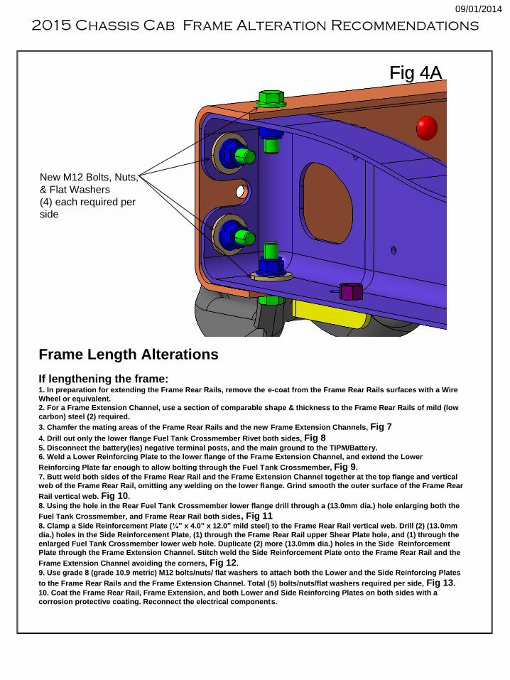
New M12 Bolts, Nuts,
& Flat Washers
(4) each required per
side
Fig 4A
New M12 Bolts, Nuts,
& Flat Washers
(4) each required per
side
Fig 4A
Frame Length Alterations
If lengthening the frame:1. In preparation for extending the Frame Rear Rails, remove the e-coat from the Frame Rear Rails surfaces with a Wire
Wheel or equivalent.
2. For a Frame Extension Channel, use a section of comparable shape & thickness to the Frame Rear Rails of mild (low
carbon) steel (2) required.
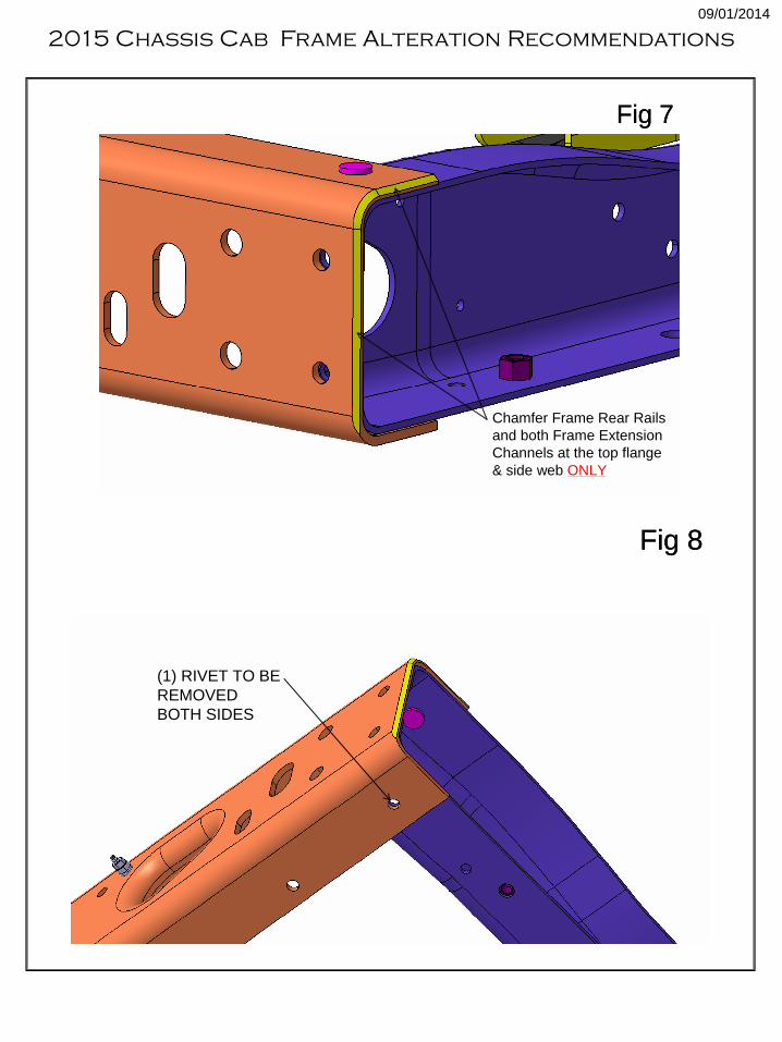
3. Chamfer the mating areas of the Frame Rear Rails and the new Frame Extension Channels, Fig 7
4. Drill out only the lower flange Fuel Tank Crossmember Rivet both sides, Fig 85. Disconnect the battery(ies) negative terminal posts, and the main ground to the TIPM/Battery.
6. Weld a Lower Reinforcing Plate to the lower flange of the Frame Extension Channel, and extend the Lower
Reinforcing Plate far enough to allow bolting through the Fuel Tank Crossmember, Fig 9.
7. Butt weld both sides of the Frame Rear Rail and the Frame Extension Channel together at the top flange and vertical
web of the Frame Rear Rail, omitting any welding on the lower flange. Grind smooth the outer surface of the Frame Rear
Rail vertical web. Fig 10.
8. Using the hole in the Rear Fuel Tank Crossmember lower flange drill through a (13.0mm dia.) hole enlarging both the
Fuel Tank Crossmember, and Frame Rear Rail both sides, Fig 118. Clamp a Side Reinforcement Plate (¼” x 4.0” x 12.0” mild steel) to the Frame Rear Rail vertical web. Drill (2) (13.0mm
dia.) holes in the Side Reinforcement Plate, (1) through the Frame Rear Rail upper Shear Plate hole, and (1) through the
enlarged Fuel Tank Crossmember lower web hole. Duplicate (2) more (13.0mm dia.) holes in the Side Reinforcement
Plate through the Frame Extension Channel. Stitch weld the Side Reinforcement Plate onto the Frame Rear Rail and the
Frame Extension Channel avoiding the corners, Fig 12.
9. Use grade 8 (grade 10.9 metric) M12 bolts/nuts/ flat washers to attach both the Lower and the Side Reinforcing Plates
to the Frame Rear Rails and the Frame Extension Channel. Total (5) bolts/nuts/flat washers required per side, Fig 13.
10. Coat the Frame Rear Rail, Frame Extension, and both Lower and Side Reinforcing Plates on both sides with a
corrosion protective coating. Reconnect the electrical components.
2015 Chassis Cab Frame Alteration Recommendations
09/01/2014
Chamfer Frame Rear Rails
and both Frame Extension
Channels at the top flange
& side web ONLY
Fig 7
Chamfer Frame Rear Rails
and both Frame Extension
Channels at the top flange
& side web ONLY
Fig 7
Fig 8
(1) RIVET TO BE
REMOVED
BOTH SIDES
Fig 8
(1) RIVET TO BE
REMOVED
BOTH SIDES
2015 Chassis Cab Frame Alteration Recommendations
09/01/2014
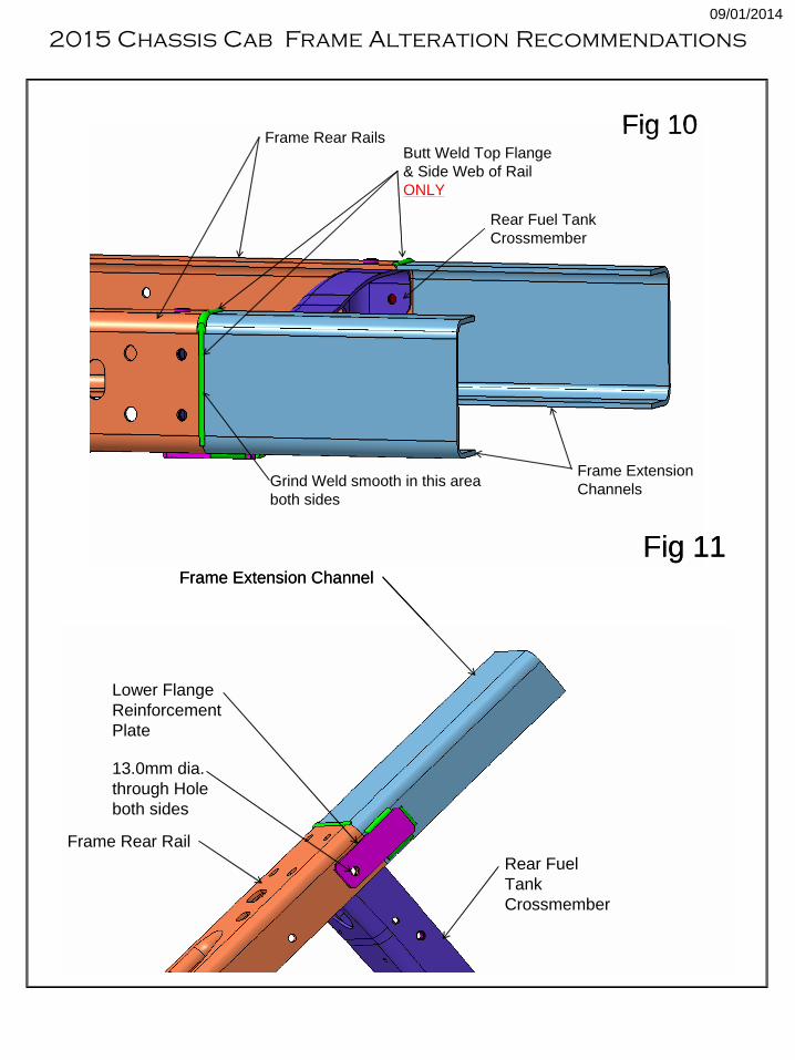
Butt Weld Top Flange
& Side Web of Rail
ONLY
Frame Extension
Channels
Rear Fuel Tank
Crossmember
Frame Rear Rails
Grind Weld smooth in this area
both sides
Fig 10Butt Weld Top Flange
& Side Web of Rail
ONLY
Frame Extension
Channels
Rear Fuel Tank
Crossmember
Frame Rear Rails
Grind Weld smooth in this area
both sides
Fig 10
Fig 11Frame Extension Channel
Lower Flange
Reinforcement
Plate
Rear Fuel
Tank
Crossmember
13.0mm dia.
through Hole
both sides
Frame Rear Rail
Fig 11Frame Extension Channel
Lower Flange
Reinforcement
Plate
Rear Fuel
Tank
Crossmember
13.0mm dia.
through Hole
both sides
Frame Rear Rail
2015 Chassis Cab Frame Alteration Recommendations
09/01/2014
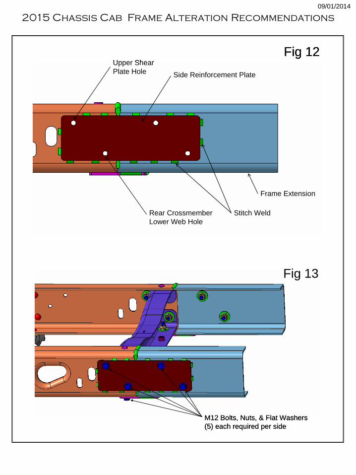
Frame Extension
Side Reinforcement Plate
Upper Shear
Plate Hole
Rear Crossmember
Lower Web Hole
Stitch Weld
Fig 12
Frame Extension
Side Reinforcement Plate
Upper Shear
Plate Hole
Rear Crossmember
Lower Web Hole
Stitch Weld
Fig 12
Fig 13
M12 Bolts, Nuts, & Flat Washers
(5) each required per side
Fig 13
M12 Bolts, Nuts, & Flat Washers
(5) each required per side
2015 Chassis Cab Frame Alteration Recommendations
09/01/2014