
Foundation Fieldbus Overview - pacontrol.com · Technical Overview FOUNDATION™ fieldbus...
43
Technical Overview FOUNDATION ™ fieldbus “Freedom to Choose. Power to Integrate.” Compliments of: FD-043 Rev 3.0
Transcript of Foundation Fieldbus Overview - pacontrol.com · Technical Overview FOUNDATION™ fieldbus...
TechnicalOverviewFOUNDATION™ fieldbus
“Freedom to Choose. Power to Integrate.”
Compliments of:
FD-043 Rev 3.0

© 1996 (Rev.1998, 2003) Fieldbus Foundation, Austin, Texas. All rights reserved.
FOUNDATION Fieldbus Technical OverviewFD-043 Revision 3.0
This overview has been prepared to aid understanding of the technical aspects of FOUNDATIONfieldbus.
The booklet begins with a brief summary of fieldbus benefits followed by the goals, principlesand organization of the not-for-profit Fieldbus Foundation.
The main portion of the booklet is devoted to the definition and explanation of key technicalconcepts inherent in FOUNDATION fieldbus technology.
I sincerely hope this information proves useful to you. Please contact the Fieldbus Foundationif you need additional information about this exciting new technology.
David A. GlanzerDirector of Technology Development
For additional information please contact:
Fieldbus Foundation9005 Mountain Ridge Drive
Bowie Bldg., Suite 190Austin, TX 78759-5316
USA
Voice: (512) 794-8890Fax: (512) 794-8893
Visit our World Wide Web Site:http://www.fieldbus.org
DISCLAIMER OF WARRANTIES
This document is provided on an “as is” basis and may be subject to future additions, modifications, or corrections. The FieldbusFoundation hereby disclaims all warranties of any kind, express or implied, including any warranty of merchantability or fitness fora particular purpose, for this document. In no event will the Fieldbus Foundation be responsible for any loss or damage arisingout of or resulting from any defect, error or omission in this document or from anyone’s use of or reliance on this document.
Preface
© 1996 (Rev.1998, 2003) Fieldbus Foundation, Austin, Texas. All rights reserved.
1.0 WHAT IS FOUNDATION FIELDBUS? . . . . . . . . . . . . . . . . . . . . . . . . . . . . . . . . . . . . . . . . . . . . . . . . . . . . .1
1.1 H1 Benefits . . . . . . . . . . . . . . . . . . . . . . . . . . . . . . . . . . . . . . . . . . . . . . . . . . . . . . . . . . . . . . . . . . .1
1.1.1 More Data Available . . . . . . . . . . . . . . . . . . . . . . . . . . . . . . . . . . . . . . . . . . . . . . . . . . . . . . . . . .2
1.1.2 Expanded View of the Process and Instruments . . . . . . . . . . . . . . . . . . . . . . . . . . . . . . . . . . . .2
1.1.3 Reduction in System Hardware . . . . . . . . . . . . . . . . . . . . . . . . . . . . . . . . . . . . . . . . . . . . . . . . .2
1.1.4 Wiring Savings . . . . . . . . . . . . . . . . . . . . . . . . . . . . . . . . . . . . . . . . . . . . . . . . . . . . . . . . . . . . . .3
1.2 HSE Benefits . . . . . . . . . . . . . . . . . . . . . . . . . . . . . . . . . . . . . . . . . . . . . . . . . . . . . . . . . . . . . . . . . .3
1.2.1 High Performance . . . . . . . . . . . . . . . . . . . . . . . . . . . . . . . . . . . . . . . . . . . . . . . . . . . . . . . . . . .3
1.2.2 Subsystem Interoperability . . . . . . . . . . . . . . . . . . . . . . . . . . . . . . . . . . . . . . . . . . . . . . . . . . . . .3
1.2.3 Function Blocks . . . . . . . . . . . . . . . . . . . . . . . . . . . . . . . . . . . . . . . . . . . . . . . . . . . . . . . . . . . . .3
1.2.4 Control Backbone . . . . . . . . . . . . . . . . . . . . . . . . . . . . . . . . . . . . . . . . . . . . . . . . . . . . . . . . . . .3
1.2.5 Standard Ethernet . . . . . . . . . . . . . . . . . . . . . . . . . . . . . . . . . . . . . . . . . . . . . . . . . . . . . . . . . . .3
2.0 WHO IS THE FIELDBUS FOUNDATION? . . . . . . . . . . . . . . . . . . . . . . . . . . . . . . . . . . . . . . . . . . . . . . . .4
2.1 Organization . . . . . . . . . . . . . . . . . . . . . . . . . . . . . . . . . . . . . . . . . . . . . . . . . . . . . . . . . . . . . . . . . .4
2.1.1 Members . . . . . . . . . . . . . . . . . . . . . . . . . . . . . . . . . . . . . . . . . . . . . . . . . . . . . . . . . . . . . . . . . .4
2.1.2 Board of Directors . . . . . . . . . . . . . . . . . . . . . . . . . . . . . . . . . . . . . . . . . . . . . . . . . . . . . . . . . . .4
2.1.3 President . . . . . . . . . . . . . . . . . . . . . . . . . . . . . . . . . . . . . . . . . . . . . . . . . . . . . . . . . . . . . . . . . .4
2.1.4 End User Advisory Council . . . . . . . . . . . . . . . . . . . . . . . . . . . . . . . . . . . . . . . . . . . . . . . . . . . .4
2.1.5 End User Councils . . . . . . . . . . . . . . . . . . . . . . . . . . . . . . . . . . . . . . . . . . . . . . . . . . . . . . . . . . .4
2.1.6 Quality Director . . . . . . . . . . . . . . . . . . . . . . . . . . . . . . . . . . . . . . . . . . . . . . . . . . . . . . . . . . . . .5
2.1.7 Executive Committee . . . . . . . . . . . . . . . . . . . . . . . . . . . . . . . . . . . . . . . . . . . . . . . . . . . . . . . . .5
2.1.8 Technical Teams . . . . . . . . . . . . . . . . . . . . . . . . . . . . . . . . . . . . . . . . . . . . . . . . . . . . . . . . . . . .5
2.1.9 Marketing Teams . . . . . . . . . . . . . . . . . . . . . . . . . . . . . . . . . . . . . . . . . . . . . . . . . . . . . . . . . . . .5
2.1.10 Member Support . . . . . . . . . . . . . . . . . . . . . . . . . . . . . . . . . . . . . . . . . . . . . . . . . . . . . . . . . . . .5
3.0 FOUNDATION FIELDBUS TECHNOLOGY . . . . . . . . . . . . . . . . . . . . . . . . . . . . . . . . . . . . . . . . . . . . . . . . .5
3.1 User Application – Blocks . . . . . . . . . . . . . . . . . . . . . . . . . . . . . . . . . . . . . . . . . . . . . . . . . . . . . . . .6
3.1.1 Resource Block . . . . . . . . . . . . . . . . . . . . . . . . . . . . . . . . . . . . . . . . . . . . . . . . . . . . . . . . . . . . .6
3.1.2 Function Block . . . . . . . . . . . . . . . . . . . . . . . . . . . . . . . . . . . . . . . . . . . . . . . . . . . . . . . . . . . . .6
3.1.3 Transducer Blocks . . . . . . . . . . . . . . . . . . . . . . . . . . . . . . . . . . . . . . . . . . . . . . . . . . . . . . . . . . .7
3.1.3.1 Supporting Objects . . . . . . . . . . . . . . . . . . . . . . . . . . . . . . . . . . . . . . . . . . . . . . . . . . . . . . . .7
3.1.4 Fieldbus Device Definition . . . . . . . . . . . . . . . . . . . . . . . . . . . . . . . . . . . . . . . . . . . . . . . . . . . . .9
3.2 Function Block Scheduling . . . . . . . . . . . . . . . . . . . . . . . . . . . . . . . . . . . . . . . . . . . . . . . . . . . . . . .9
3.2.1 Application Clock Distribution . . . . . . . . . . . . . . . . . . . . . . . . . . . . . . . . . . . . . . . . . . . . . . . . .10
3.2.2 Device Address Assignment . . . . . . . . . . . . . . . . . . . . . . . . . . . . . . . . . . . . . . . . . . . . . . . . . . .10
3.2.3 Find Tag Service . . . . . . . . . . . . . . . . . . . . . . . . . . . . . . . . . . . . . . . . . . . . . . . . . . . . . . . . . . . .10
3.3 Device Descriptions . . . . . . . . . . . . . . . . . . . . . . . . . . . . . . . . . . . . . . . . . . . . . . . . . . . . . . . . . . . .11
3.3.1 Device Description Tokenizer . . . . . . . . . . . . . . . . . . . . . . . . . . . . . . . . . . . . . . . . . . . . . . . . . .11
3.3.2 Device Description Services (DDS) . . . . . . . . . . . . . . . . . . . . . . . . . . . . . . . . . . . . . . . . . . . . . .12
3.3.3 Device Description Hierarchy . . . . . . . . . . . . . . . . . . . . . . . . . . . . . . . . . . . . . . . . . . . . . . . . . .12
3.3.4 Capability Files . . . . . . . . . . . . . . . . . . . . . . . . . . . . . . . . . . . . . . . . . . . . . . . . . . . . . . . . . . . .13
Table of Contents
© 1996 (Rev.1998, 2003) Fieldbus Foundation, Austin, Texas. All rights reserved.
3.4 H1 Communication Stack . . . . . . . . . . . . . . . . . . . . . . . . . . . . . . . . . . . . . . . . . . . . . . . . . . . . . . .14
3.4.1 The Data Link Layer (DLL) . . . . . . . . . . . . . . . . . . . . . . . . . . . . . . . . . . . . . . . . . . . . . . . . . . . .14
3.4.1.1 Device Types . . . . . . . . . . . . . . . . . . . . . . . . . . . . . . . . . . . . . . . . . . . . . . . . . . . . . . . . . . .15
3.4.1.2 Scheduled Communication . . . . . . . . . . . . . . . . . . . . . . . . . . . . . . . . . . . . . . . . . . . . . . . . .15
3.4.1.3 Unscheduled Communication . . . . . . . . . . . . . . . . . . . . . . . . . . . . . . . . . . . . . . . . . . . . . . .16
3.4.1.4 Link Active Scheduler Operation . . . . . . . . . . . . . . . . . . . . . . . . . . . . . . . . . . . . . . . . . . . . .16
3.4.1.4.1 CD Schedule . . . . . . . . . . . . . . . . . . . . . . . . . . . . . . . . . . . . . . . . . . . . . . . . . . . . . . . . .16
3.4.1.4.2 Live List Maintenance . . . . . . . . . . . . . . . . . . . . . . . . . . . . . . . . . . . . . . . . . . . . . . . . . .16
3.4.1.4.3 Data Link Time Synchronization . . . . . . . . . . . . . . . . . . . . . . . . . . . . . . . . . . . . . . . . . .17
3.4.1.4.4 Token Passing . . . . . . . . . . . . . . . . . . . . . . . . . . . . . . . . . . . . . . . . . . . . . . . . . . . . . . . .17
3.4.1.4.5 LAS Redundancy . . . . . . . . . . . . . . . . . . . . . . . . . . . . . . . . . . . . . . . . . . . . . . . . . . . . .17
3.4.2 System Management . . . . . . . . . . . . . . . . . . . . . . . . . . . . . . . . . . . . . . . . . . . . . . . . . . . . . . . .17
3.4.3 Fieldbus Access Sublayer (FAS) . . . . . . . . . . . . . . . . . . . . . . . . . . . . . . . . . . . . . . . . . . . . . . . .17
3.4.3.1 Client/Server VCR Type . . . . . . . . . . . . . . . . . . . . . . . . . . . . . . . . . . . . . . . . . . . . . . . . . . . .17
3.4.3.2 Report Distribution VCR Type . . . . . . . . . . . . . . . . . . . . . . . . . . . . . . . . . . . . . . . . . . . . . . .18
3.4.3.3 Publisher/Server VCR Type . . . . . . . . . . . . . . . . . . . . . . . . . . . . . . . . . . . . . . . . . . . . . . . . .18
3.4.3.4 Summary of VCR Types . . . . . . . . . . . . . . . . . . . . . . . . . . . . . . . . . . . . . . . . . . . . . . . . . . .18
3.4.4 Fieldbus Message Specification (FMS) . . . . . . . . . . . . . . . . . . . . . . . . . . . . . . . . . . . . . . . . . . .18
3.4.4.1 Virtual Field Device (VFD) . . . . . . . . . . . . . . . . . . . . . . . . . . . . . . . . . . . . . . . . . . . . . . . . . .19
3.4.4.2 FMS Services . . . . . . . . . . . . . . . . . . . . . . . . . . . . . . . . . . . . . . . . . . . . . . . . . . . . . . . . . . .19
3.4.4.2.1 Context Management Services . . . . . . . . . . . . . . . . . . . . . . . . . . . . . . . . . . . . . . . . . . .19
3.4.4.2.2 Object Dictionary Services . . . . . . . . . . . . . . . . . . . . . . . . . . . . . . . . . . . . . . . . . . . . . .19
3.4.4.2.3 Variable Access Services . . . . . . . . . . . . . . . . . . . . . . . . . . . . . . . . . . . . . . . . . . . . . . . .19
3.4.4.2.4 Event Services . . . . . . . . . . . . . . . . . . . . . . . . . . . . . . . . . . . . . . . . . . . . . . . . . . . . . . .19
3.4.4.2.5 Upload/Download Services . . . . . . . . . . . . . . . . . . . . . . . . . . . . . . . . . . . . . . . . . . . . . .20
3.4.4.2.6 Program Invocation Services . . . . . . . . . . . . . . . . . . . . . . . . . . . . . . . . . . . . . . . . . . . . .20
3.4.4.3 Message Formatting . . . . . . . . . . . . . . . . . . . . . . . . . . . . . . . . . . . . . . . . . . . . . . . . . . . . . .20
3.4.4.4 Protocol Behavior . . . . . . . . . . . . . . . . . . . . . . . . . . . . . . . . . . . . . . . . . . . . . . . . . . . . . . . .21
3.5 Physical Layer (31.25 kbit/s) . . . . . . . . . . . . . . . . . . . . . . . . . . . . . . . . . . . . . . . . . . . . . . . . . . . . . .21
3.5.1 31.25 kbit/s Fieldbus Signaling . . . . . . . . . . . . . . . . . . . . . . . . . . . . . . . . . . . . . . . . . . . . . . . .22
3.5.2 31.25 kbit/s Fieldbus Wiring . . . . . . . . . . . . . . . . . . . . . . . . . . . . . . . . . . . . . . . . . . . . . . . . . . .23
3.6 HSE Communication Stack . . . . . . . . . . . . . . . . . . . . . . . . . . . . . . . . . . . . . . . . . . . . . . . . . . . . . .24
3.6.1 HSE Device Types . . . . . . . . . . . . . . . . . . . . . . . . . . . . . . . . . . . . . . . . . . . . . . . . . . . . . . . .24
3.6.1.1 HSE Device . . . . . . . . . . . . . . . . . . . . . . . . . . . . . . . . . . . . . . . . . . . . . . . . . . . . . . . . . . . .24
3.6.1.2 Linking Device . . . . . . . . . . . . . . . . . . . . . . . . . . . . . . . . . . . . . . . . . . . . . . . . . . . . . . . . . .24
3.6.1.3 Gateway Device . . . . . . . . . . . . . . . . . . . . . . . . . . . . . . . . . . . . . . . . . . . . . . . . . . . . . . . . .24
3.6.1.4 Host Device (OPC DA Server) . . . . . . . . . . . . . . . . . . . . . . . . . . . . . . . . . . . . . . . . . . . . . . .24
3.6.2 Ethernet Presence . . . . . . . . . . . . . . . . . . . . . . . . . . . . . . . . . . . . . . . . . . . . . . . . . . . . . . . .24
3.6.3 Field Device Access (FDA) . . . . . . . . . . . . . . . . . . . . . . . . . . . . . . . . . . . . . . . . . . . . . . . . . .25
3.6.4 HSE System Management . . . . . . . . . . . . . . . . . . . . . . . . . . . . . . . . . . . . . . . . . . . . . . . . . .25
3.6.5 HSE Network Management . . . . . . . . . . . . . . . . . . . . . . . . . . . . . . . . . . . . . . . . . . . . . . . . .25
Table of Contents
3.7 Redundancy . . . . . . . . . . . . . . . . . . . . . . . . . . . . . . . . . . . . . . . . . . . . . . . . . . . . . . . . . . . . . . . . . .25
3.7.1 Need for Host-Level Redundancy . . . . . . . . . . . . . . . . . . . . . . . . . . . . . . . . . . . . . . . . . . . .26
3.7.2. Media Redundancy . . . . . . . . . . . . . . . . . . . . . . . . . . . . . . . . . . . . . . . . . . . . . . . . . . . . . . .26
3.7.3 Complete Network Redundancy . . . . . . . . . . . . . . . . . . . . . . . . . . . . . . . . . . . . . . . . . . . . . .26
3.7.4 Device Redundancy . . . . . . . . . . . . . . . . . . . . . . . . . . . . . . . . . . . . . . . . . . . . . . . . . . . . . . .27
3.7.5 LAN Topologies . . . . . . . . . . . . . . . . . . . . . . . . . . . . . . . . . . . . . . . . . . . . . . . . . . . . . . . . . .28
4.0 SYSTEM CONFIGURATION . . . . . . . . . . . . . . . . . . . . . . . . . . . . . . . . . . . . . . . . . . . . . . . . . . . . . . . . .29
4.1 System Design . . . . . . . . . . . . . . . . . . . . . . . . . . . . . . . . . . . . . . . . . . . . . . . . . . . . . . . . . . . . . . . .29
4.2 Device Configuration . . . . . . . . . . . . . . . . . . . . . . . . . . . . . . . . . . . . . . . . . . . . . . . . . . . . . . . . . . . . . . . . .29
5.0 FIELD TEST SYSTEM . . . . . . . . . . . . . . . . . . . . . . . . . . . . . . . . . . . . . . . . . . . . . . . . . . . . . . . . . . . . . .30
5.1 Test Instrumentation . . . . . . . . . . . . . . . . . . . . . . . . . . . . . . . . . . . . . . . . . . . . . . . . . . . . . . . . . . .30
5.2 Installation, Startup, and Operation Benefits Observed . . . . . . . . . . . . . . . . . . . . . . . . . . . . . . .31
6.0 FEATURES SUMMARY . . . . . . . . . . . . . . . . . . . . . . . . . . . . . . . . . . . . . . . . . . . . . . . . . . . . . . . . . . . . .32
7.0 REFERENCES . . . . . . . . . . . . . . . . . . . . . . . . . . . . . . . . . . . . . . . . . . . . . . . . . . . . . . . . . . . . . . . . . . . .36
8.0 DOCUMENT LIST . . . . . . . . . . . . . . . . . . . . . . . . . . . . . . . . . . . . . . . . . . . . . . . . . . . . . . . . . . . . . . . . .36
9.0 ACRONYM TABLE . . . . . . . . . . . . . . . . . . . . . . . . . . . . . . . . . . . . . . . . . . . . . . . . . . . . . . . . . . . . . . . .37
10.0 TERMINOLOGY . . . . . . . . . . . . . . . . . . . . . . . . . . . . . . . . . . . . . . . . . . . . . . . . . . . . . . . . . . . . . . . . . .37
© 1996 (Rev.1998, 2003) Fieldbus Foundation, Austin, Texas. All rights reserved.
Table of Contents
P
L
*LinkingDevice Plant/Factory
Workstations
I/O PLC PLC
H1 HSE*
Data Service
MIS/ERP/HMI/
Data Services
Business Enterpriseand
Plant Application Packages
H1 and NSE
Planningand
InstallationOperation Maintenance Evolution
Reduced number of wires and marshaling panels
Reduced number of power supplies and cabinetsReduced size of equipment rooms
More information available for operations
Increased uptime due to less equipment, better self diagnostics, and remote diagnostics
Increased accuracy of measurementsEasier evolution due to standardized function blocksIncreased sophistication and flexibility of instrumentation
Remote configuration of devices
Reduced number of intrinsic safety barriersReduced number of input/output converters
Figure 3
Figure 1
Figure 2 Figure 3
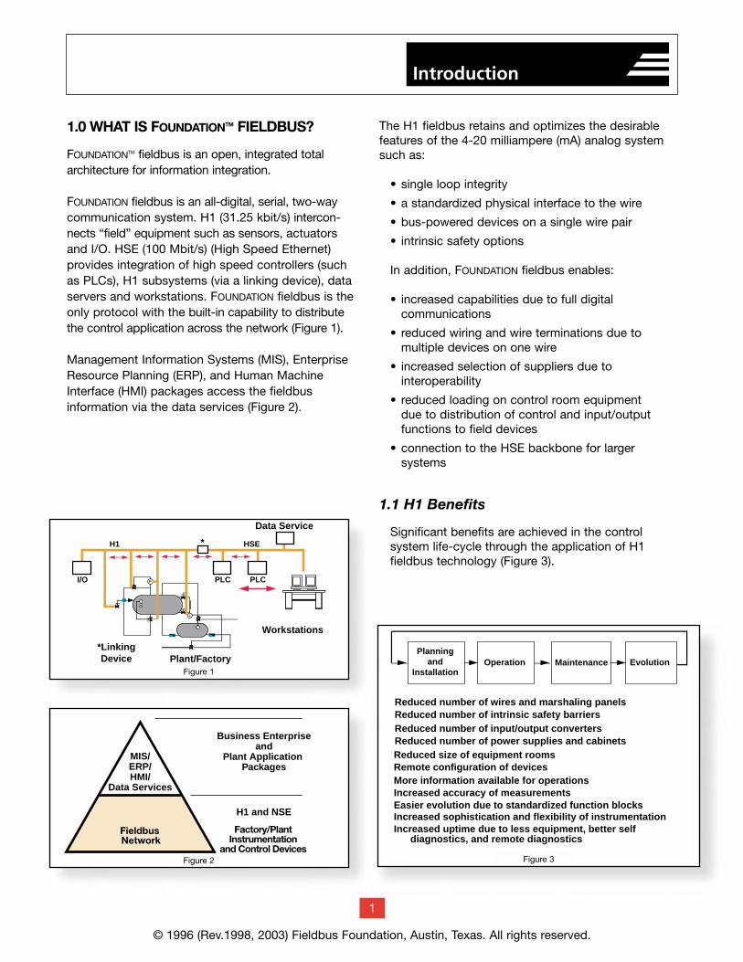
1.0 WHAT IS FOUNDATIONTM FIELDBUS?
FOUNDATIONTM fieldbus is an open, integrated total architecture for information integration.
FOUNDATION fieldbus is an all-digital, serial, two-waycommunication system. H1 (31.25 kbit/s) intercon-nects “field” equipment such as sensors, actuators and I/O. HSE (100 Mbit/s) (High Speed Ethernet) provides integration of high speed controllers (such as PLCs), H1 subsystems (via a linking device), dataservers and workstations. FOUNDATION fieldbus is theonly protocol with the built-in capability to distribute the control application across the network (Figure 1).
Management Information Systems (MIS), EnterpriseResource Planning (ERP), and Human MachineInterface (HMI) packages access the fieldbus information via the data services (Figure 2).
The H1 fieldbus retains and optimizes the desirablefeatures of the 4-20 milliampere (mA) analog systemsuch as:
• single loop integrity
• a standardized physical interface to the wire
• bus-powered devices on a single wire pair
• intrinsic safety options
In addition, FOUNDATION fieldbus enables:
• increased capabilities due to full digital communications
• reduced wiring and wire terminations due to multiple devices on one wire
• increased selection of suppliers due to interoperability
• reduced loading on control room equipment due to distribution of control and input/outputfunctions to field devices
• connection to the HSE backbone for larger systems
1.1 H1 Benefits
Significant benefits are achieved in the control system life-cycle through the application of H1 fieldbus technology (Figure 3).
© 1996 (Rev.1998, 2003) Fieldbus Foundation, Austin, Texas. All rights reserved.
1
Introduction
Traditional 4-20 mA WiringOne I.S. Barrier, One Wire
for Each Device
Fieldbus Wiring
One I.S. Barrier, One Wirefor
Many Devices
Controller
Control System Network
H1
4-20 mA
Input/OutputSubsystem
I.S. I.S. I.S.
I.S.
Linking Device
HSE
Traditional 4-20 mAOne VariableOne Direction
Fieldbus Multiple VariablesBoth Directions
Controller
Control System Network
H1
Input/OutputSubsystem
LinkingDevice
HSE
TraditionalControl and I/O
requires extra equipmnet
Fieldbus
Control and I/O infield instruments.
Controller
Control System Network
H1
4-20 mA
Input/OutputSubsystem
PID
PID
AI
AIAO
AO
LinkingDevice
HSE
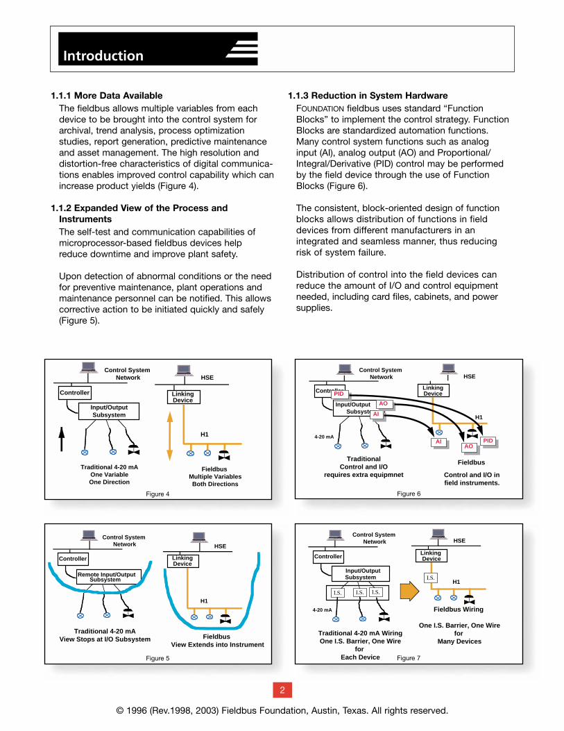
1.1.1 More Data AvailableThe fieldbus allows multiple variables from eachdevice to be brought into the control system forarchival, trend analysis, process optimization studies, report generation, predictive maintenanceand asset management. The high resolution and distortion-free characteristics of digital communica-tions enables improved control capability which canincrease product yields (Figure 4).
1.1.2 Expanded View of the Process and InstrumentsThe self-test and communication capabilities of microprocessor-based fieldbus devices help reduce downtime and improve plant safety.
Upon detection of abnormal conditions or the needfor preventive maintenance, plant operations andmaintenance personnel can be notified. This allowscorrective action to be initiated quickly and safely(Figure 5).
1.1.3 Reduction in System HardwareFOUNDATION fieldbus uses standard “FunctionBlocks” to implement the control strategy. FunctionBlocks are standardized automation functions.Many control system functions such as analog input (AI), analog output (AO) and Proportional/Integral/Derivative (PID) control may be performedby the field device through the use of FunctionBlocks (Figure 6).
The consistent, block-oriented design of function blocks allows distribution of functions in field devices from different manufacturers in anintegrated and seamless manner, thus reducingrisk of system failure.
Distribution of control into the field devices canreduce the amount of I/O and control equipmentneeded, including card files, cabinets, and powersupplies.
Traditional 4-20 mAView Stops at I/O Subsystem Fieldbus
View Extends into Instrument
Controller
Control System Network
H1
Remote Input/OutputSubsystem
LinkingDevice
HSE
Figure 5
Figure 6
© 1996 (Rev.1998, 2003) Fieldbus Foundation, Austin, Texas. All rights reserved.
Figure 4
Figure 7
2
Introduction
1.1.4 Wiring SavingsThe H1 fieldbus allows many devices to connect toa single wire pair. This results in less wire, fewerintrinsic safety barriers, and fewer marshaling cabinets (Figure 7).
1.2 HSE Benefits
In addition to the same life cycle benefits as H1,HSE provides the control backbone that integratesall of the systems in the plant.
1.2.1 High PerformanceFOUNDATION™ fieldbus enables asset managementfunctions such as diagnostics, calibration, identifica-tion and other maintenance management operationsto “mine” massive information from field devices inreal-time. Asset management allows users to moveto proactive maintenance which allocates resourcesto where they are really needed. Users employingfieldbus-based field devices and permanently connected online asset management software need HSE performance.
1.2.2 Subsystem InteroperabilityPlants are comprised of a number of subsystems.With HSE, subsystems for burner management, gas chromatographs, paper web scanners, shut-down systems, compressor controls tank farms,etc., integrate easily because of the open protocol.Users can mix and match subsystems for basiccontrol, emergency shutdown, paper quality control,advanced control and compressor control, etc.,from different suppliers. Utilizing HSE, informationcan be accessed without custom programming.Users can select decimal subsystems to keep costlow, while at the same time reducing the configura-tion effort.
Data integrity, diagnostics and redundancy manage-ment are part of HSE and work seamlessly betweendevices from different manufacturers.
1.2.3 Function BlocksThe same FOUNDATIONTM function blocks that areused in H1 devices are used in HSE devices.FOUNDATIONTM fieldbus eliminates the need for proprietary programming languages. The same control strategy programming language can be used throughout the entire system.
The status associated with function block parametersis generated by field instruments based on failed sensors, stuck valves, etc., and is used for loop shut-downs, windup protection and bumpless transfer.
1.2.4 Control BackboneHSE provides peer-to-peer communication capabili-ty. Devices communicate with each other directlywithout having to go through a central computer.This makes it possible to realize powerful, advancedcontrol strategies involving variables throughout theplant without the risk of a central computer failure,further reducing risk. HSE can also bridge informa-tion between devices on different H1 networks atdifferent ends of the plant. Thus, control can spanbetween process cells and a plant area.
HSE replaces enterprise, control and remote-I/Onetworking levels, thus flattening the enterprisepyramid.
The Linking Device (LD) brings data from one ormore H1 fieldbus networks directly onto the HSE backbone.
1.2.5 Standard EthernetStandard cable is used for HSE devices; no special tools or skills are required. Installation is simple and fast. HSE uses standard Ethernet network equipment such as switches.
Standard Commercial Off-The-Shelf (COTS)Ethernet components are made in extremely high volume. Cable, interface cards and other networking hardware are extremely low cost com-pared to proprietary networks. Ethernet options for media include twisted pair, fiber optics and wireless. Networking hardware is available in both commercial and industrial grades from many suppliers.
© 1996 (Rev.1998, 2003) Fieldbus Foundation, Austin, Texas. All rights reserved.
3
Introduction
2.0 WHO IS THE FIELDBUS FOUNDATION?
Driven by their customers’ needs, process control and manufacturing automation companies formedthe Fieldbus Foundation to complete developmentof a single, open, international, and interoperablefieldbus.
The Fieldbus Foundation is an independent, not-for-profit organization based on the following principles:
• Fieldbus technology is an enabling technology; not a differentiating technology.
• Fieldbus technology is open and available to all parties.
• Fieldbus technology is based on the work of the International Electrotechnical Commission (IEC) and ISA (the international society for measurement and control).
• Fieldbus Foundation members support and work with the international and national standards committees.
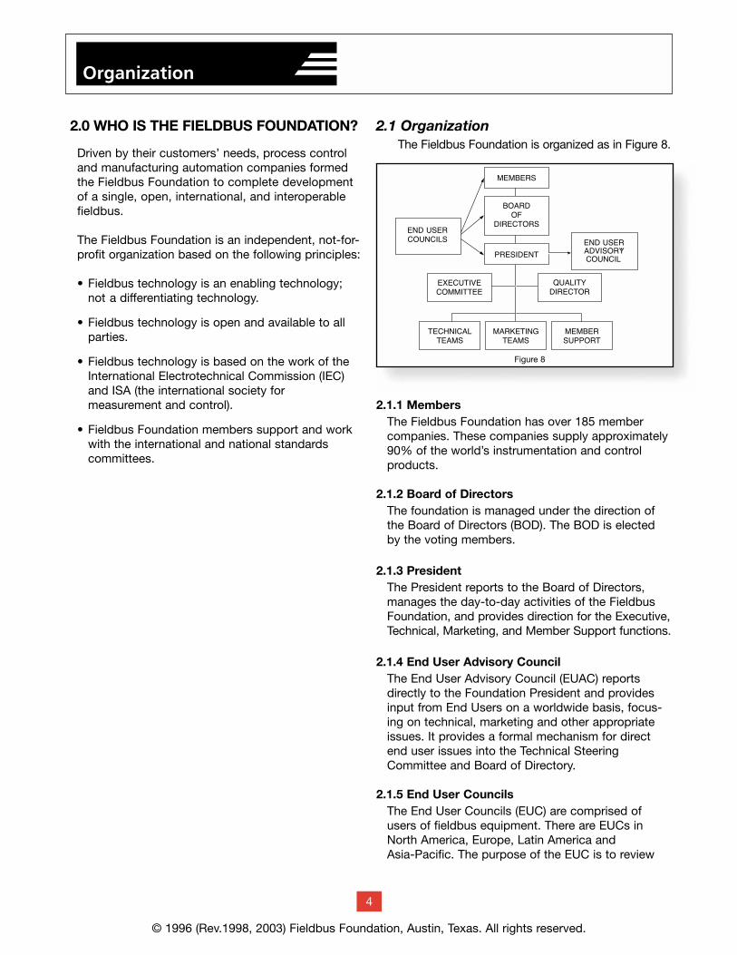
2.1 OrganizationThe Fieldbus Foundation is organized as in Figure 8.
2.1.1 MembersThe Fieldbus Foundation has over 185 membercompanies. These companies supply approximately90% of the world’s instrumentation and controlproducts.
2.1.2 Board of DirectorsThe foundation is managed under the direction ofthe Board of Directors (BOD). The BOD is electedby the voting members.
2.1.3 PresidentThe President reports to the Board of Directors,manages the day-to-day activities of the FieldbusFoundation, and provides direction for the Executive,Technical, Marketing, and Member Support functions.
2.1.4 End User Advisory CouncilThe End User Advisory Council (EUAC) reportsdirectly to the Foundation President and providesinput from End Users on a worldwide basis, focus-ing on technical, marketing and other appropriateissues. It provides a formal mechanism for directend user issues into the Technical SteeringCommittee and Board of Directory.
2.1.5 End User CouncilsThe End User Councils (EUC) are comprised ofusers of fieldbus equipment. There are EUCs inNorth America, Europe, Latin America and Asia-Pacific. The purpose of the EUC is to review
© 1996 (Rev.1998, 2003) Fieldbus Foundation, Austin, Texas. All rights reserved.
4
Organization
Figure 8
the activities of the foundation and provide input tohelp ensure the specifications meet the needs of themarketplace now and in the future, and to promotethe further adoption of the technology.
2.1.6 Quality DirectorThe Quality Director provides overall management ofthe foundation’s quality assurance systems.
2.1.7 Executive CommitteeThe Executive Committee advises the President concerning the strategic and overall operationalissues of the foundation.
2.1.8 Technical TeamsThe Technical Teams are responsible for the techni-cal work of the foundation. The technical work isgrouped into programs such as Specifications,Software, and Interoperability Testing. A ProgramManager is responsible for each technical program.
2.1.9 Marketing TeamsThe Marketing Teams are responsible for promotingFOUNDATION fieldbus and for planning and directingthe foundation’s products and services.
2.1.10 Member SupportMember Support is responsible for coordination anddelivery of the foundation’s products and services.Products and services include technical consulting
and training, newsletter printing and distribution,memberships, coordination of trade shows and fieldtests, product catalogs, Device Description software,and device registrations.
3.0 FOUNDATIONTM FIELDBUS TECHNOLOGY
FF-581 System Architecture*
*Note: References to specific documents are notedas follows: Document number and name.
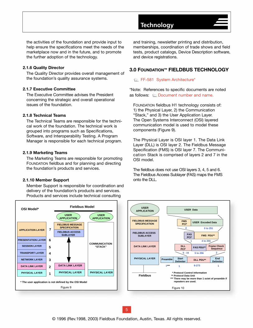
FOUNDATION fieldbus H1 technology consists of: 1) the Physical Layer, 2) the Communication“Stack,” and 3) the User Application Layer. The Open Systems Interconnect (OSI) layered communication model is used to model these components (Figure 9).
The Physical Layer is OSI layer 1. The Data Link Layer (DLL) is OSI layer 2. The Fieldbus MessageSpecification (FMS) is OSI layer 7. The Communi-cation Stack is comprised of layers 2 and 7 in theOSI model.
The fieldbus does not use OSI layers 3, 4, 5 and 6. The Fieldbus Access Sublayer (FAS) maps the FMSonto the DLL.
g
g
© 1996 (Rev.1998, 2003) Fieldbus Foundation, Austin, Texas. All rights reserved.
5
Technology
OSI Model*Fieldbus Model
TRANSPORT LAYER
SESSION LAYER
PRESENTATION LAYER
APPLICATION LAYER
PHYSICAL LAYER
DATA LINK LAYER
NETWORK LAYER
PHYSICAL LAYER
DATA LINK LAYER
FIELDBUS ACCESSSUBLAYER
FIELDBUS MESSAGESPECIFICATION
1
2
3
4
5
6
7
USERAPPLICATION
PHYSICAL LAYER
COMMUNICATION“STACK”
USERAPPLICATION
* The user application is not defined by the OSI Model
Figure 9Figure 9
Preamble StartDelimiter
EndDelimiter
11*** 18-273
DLL PDU**
4 to 2551
FASPCI*
FMS PDU**
FMS PCI*
USER Encoded Data
0 to 2514
Frame CheckSequence
5 - 15 5 to 256
FAS PDU**DLLPCI*
2
USER Data
PHYSICAL LAYER
DATA LINK LAYER
FIELDBUS ACCESS SUBLAYER
FIELDBUS MESSAGE SPECIFICATION
Fieldbus * Protocol Control Information ** Protocol Data Unit *** There may be more than 1 octet of preamble if repeaters are used.
USERAPPLICATION
Figure 10Figure 10
The User Application is not defined by the OSI model.The Fieldbus Foundation has specified a User Applicationmodel, significantly differentiating it from other models.
Each layer in the communication system is responsiblefor a portion of the message that is transmitted on thefieldbus.
Figures 10 references the approximate number of eightbit “octets” used for each layer to transfer the user data.
3.1 User Application – Blocksg FF-890 Function Block Application Process -
Part 1g FF-891 Function Block Application Process -
Part 2g FF-892 Function Block Application Process -
Part 3g FF-893 Function Block Application Process -
Part 4g FF-894 Function Block Application Process -
Part 5g FF-902 Transducer Block Application Process -
Part 1g FF-903 Transducer Block Application Process -
Part 2g TN-003 Profile & Profile Revision
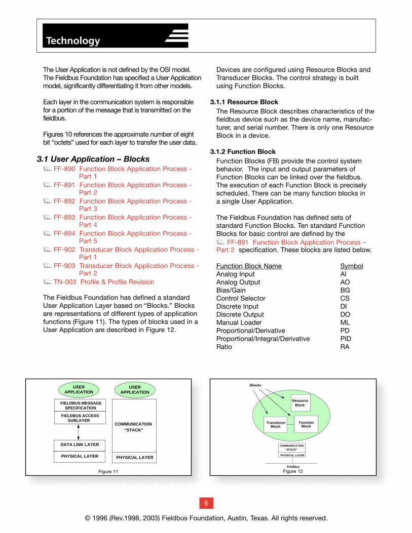
The Fieldbus Foundation has defined a standardUser Application Layer based on “Blocks.” Blocksare representations of different types of applicationfunctions (Figure 11). The types of blocks used in aUser Application are described in Figure 12.
Devices are configured using Resource Blocks andTransducer Blocks. The control strategy is builtusing Function Blocks.
3.1.1 Resource BlockThe Resource Block describes characteristics of thefieldbus device such as the device name, manufac-turer, and serial number. There is only one ResourceBlock in a device.
3.1.2 Function BlockFunction Blocks (FB) provide the control systembehavior. The input and output parameters ofFunction Blocks can be linked over the fieldbus. The execution of each Function Block is preciselyscheduled. There can be many function blocks in a single User Application.
The Fieldbus Foundation has defined sets of standard Function Blocks. Ten standard FunctionBlocks for basic control are defined by the g FF-891 Function Block Application Process –Part 2 specification. These blocks are listed below.
Function Block Name SymbolAnalog Input AIAnalog Output AOBias/Gain BGControl Selector CSDiscrete Input DIDiscrete Output DOManual Loader MLProportional/Derivative PDProportional/Integral/Derivative PIDRatio RA
© 1996 (Rev.1998, 2003) Fieldbus Foundation, Austin, Texas. All rights reserved.
6
Technology
Figure 31
PHYSICAL LAYER
DATA LINK LAYER
FIELDBUS ACCESSSUBLAYER
FIELDBUS MESSAGESPECIFICATION
USERAPPLICATION
PHYSICAL LAYER
COMMUNICATION“STACK”
USERAPPLICATION
ResourceBlock
TransducerBlock
FunctionBlock
Fieldbus
PHYSICAL LAYER
COMMUNICATION“STACK”
Blocks
Figure 32Figure 12Figure 11
© 1996 (Rev.1998, 2003) Fieldbus Foundation, Austin, Texas. All rights reserved.
Technology
The following eleven standard function blocks aredefined by the g FF-892 Function BlockApplication Process – Part 3.
Function Block Name SymbolDevice Control DCOutput Splitter OSSignal Characterizer SCLead Lag LLDeadtime DTIntegrator (Totalizer) ITSetpoint Ramp Generator SPGInput Selector ISArithmetic ARTimer TMRAnalog Alarm AAL
The following four standard function blocks aredefined by the g FF-893 Function BlockApplication Process – Part 4.
Function Block Name SymbolMultiple Analog Input MAIMultiple Analog Output MAOMultiple Discrete Input MDIMultiple Discrete Output MDO
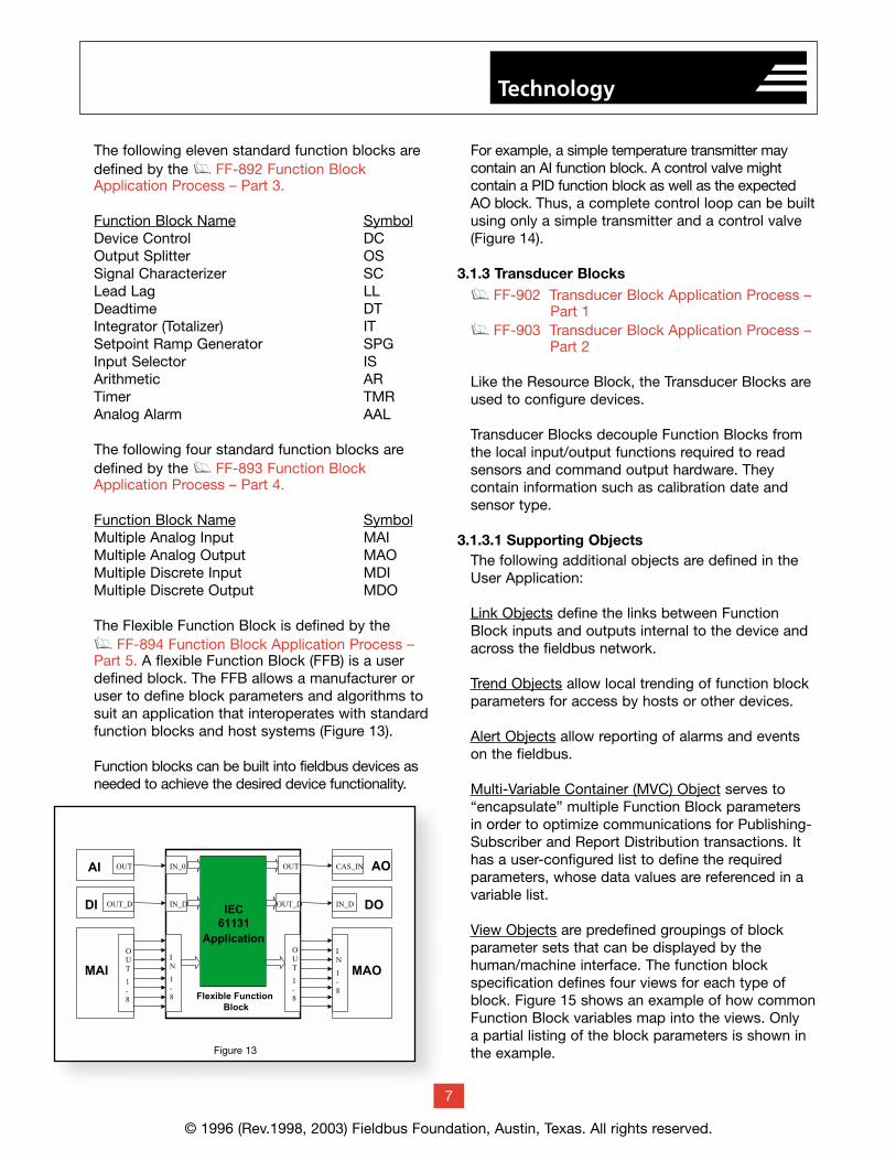
The Flexible Function Block is defined by the g FF-894 Function Block Application Process – Part 5. A flexible Function Block (FFB) is a userdefined block. The FFB allows a manufacturer oruser to define block parameters and algorithms tosuit an application that interoperates with standardfunction blocks and host systems (Figure 13).
Function blocks can be built into fieldbus devices asneeded to achieve the desired device functionality.
For example, a simple temperature transmitter maycontain an AI function block. A control valve might contain a PID function block as well as the expectedAO block. Thus, a complete control loop can be builtusing only a simple transmitter and a control valve (Figure 14).
3.1.3 Transducer Blocksg FF-902 Transducer Block Application Process –
Part 1g FF-903 Transducer Block Application Process –
Part 2
Like the Resource Block, the Transducer Blocks areused to configure devices.
Transducer Blocks decouple Function Blocks fromthe local input/output functions required to readsensors and command output hardware. They contain information such as calibration date andsensor type.
3.1.3.1 Supporting ObjectsThe following additional objects are defined in theUser Application:
Link Objects define the links between FunctionBlock inputs and outputs internal to the device andacross the fieldbus network.
Trend Objects allow local trending of function blockparameters for access by hosts or other devices.
Alert Objects allow reporting of alarms and eventson the fieldbus.
Multi-Variable Container (MVC) Object serves to“encapsulate” multiple Function Block parametersin order to optimize communications for Publishing-Subscriber and Report Distribution transactions. Ithas a user-configured list to define the requiredparameters, whose data values are referenced in avariable list.
View Objects are predefined groupings of blockparameter sets that can be displayed by the human/machine interface. The function block specification defines four views for each type ofblock. Figure 15 shows an example of how commonFunction Block variables map into the views. Only a partial listing of the block parameters is shown inthe example.
MAI
O
U
T
1
-
8
AI OUT
DI OUT_D
MAO
I
N
1
-
8
AOCAS_IN
DOIN_D
IN_0
I
N
1
-
8
IN_D IEC61131
Application
Flexible Function Block
O
U
T
1
-
8
OUT_D
OUT
Figure 13
7
Technology
Resource Block
Function Block 2
TransducerBlock 2
TrendObject View
Lists
Function Block Application
Function Block 1
TransducerBlock 1
ViewLists
Links
Alerts
Sensor1
Sensor2
MVC
Figure 16
Data Trend Alarms
DiagnosticsDetail Display
AI PID, AO
Fieldbus
Display Sets
SP X XPV X XSP HI LIMIT XCAS IN XGAIN X
View_1 OperationDynamic
View_2 Operation
StaticView_3
All DynamicView_4
Other StaticXYZ Block
AI
Static
Dynamic
Figure 34
Figure 15
PhysicalLayer
User Application
VirtualField Device
Object Descriptions
Index0
201202
210
250
Directory
Resource Block
Transducer Block
Link Objects
Trend Objects
OD Header
500 Function Block
Function Block600
1000
2000
View Object
View Object
400
Fieldbus
Function Block Application
Resource Block
Function Block 2
TransducerBlock 2
TrendObject View
Lists
Function Block 1
TransducerBlock 1
ViewLists
Links
Alerts
Stack
Figure 37Figure 18
OD HEADER0
FUNCTION BLOCKS
TRANSDUCER BLOCKS
DIRECTORY
LINK OBJECTS
TREND OBJECTS
RESOURCE BLOCK
ALERT OBJECTS
VIEW OBJECTS
Figure 36Figure 17
© 1996 (Rev.1998, 2003) Fieldbus Foundation, Austin, Texas. All rights reserved.
8
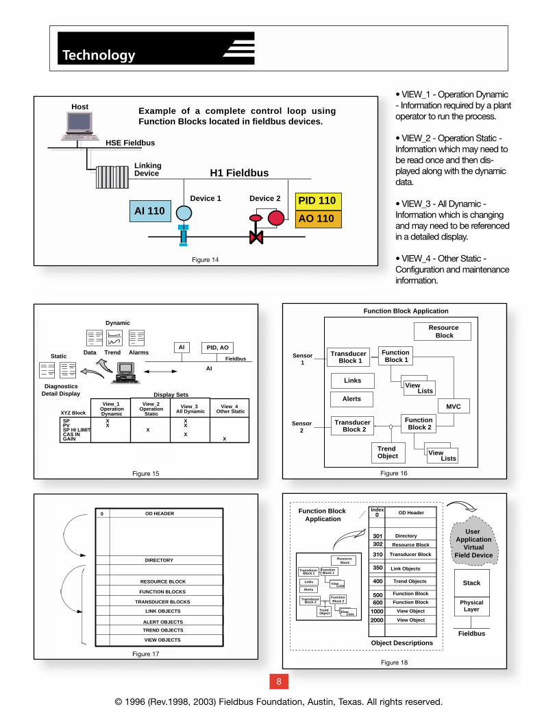
• VIEW_1 - Operation Dynamic- Information required by a plantoperator to run the process.
• VIEW_2 - Operation Static -Information which may need tobe read once and then dis-played along with the dynamicdata.
• VIEW_3 - All Dynamic -Information which is changingand may need to be referencedin a detailed display.
• VIEW_4 - Other Static -Configuration and maintenanceinformation.
AO 110AI 110
PID 110
H1 Fieldbus
Example of a complete control loop using Function Blocks located in fieldbus devices.
Device 1 Device 2
LinkingDevice
HSE Fieldbus
Host
Figure 14
3.1.4 Fieldbus Device DefinitionThe fieldbus device definition is intended for remoteI/O devices having many function blocks from whichdata shall be communicated
The function of a fieldbus device is determined bythe arrangement and interconnection of blocks(Figure 16).
The device functions are made visible to the fieldbuscommunication system through the User ApplicationVirtual Field Device (VFD) discussed in Section 3.4.3.1.
The header of the User Application object dictionarypoints to a Directory which is always the first entry inthe function block application. The Directory providesthe starting indexes of all of the other entries used inthe Function Block application (Figure 17). The VFDobject descriptions and their associated data areaccessed remotely over the fieldbus network usingVirtual Communication Relationships (VCRs).
g TN-003 Profile and Profile Revision
Each block has a “Profile” (i.e. a code) that indicatesthe type of block (e.g. the standard PID block iscode 0108 in hexadecimal). Based on this code a host can tell if a block is a standard block, anenhanced block or a manufacturer custom block.The engineering tool can now build a control strategy completely independent of the device youwill eventually use. The process engineer can buildthe control strategy and then let the instrument engineers assign the blocks to devices later.
For example, in the basic PID control template thestandard “0108” FF PID block is used. When theblock is later assigned to a device the engineeringtool confirms with the Capability File of the devicethat “0108” standard PID is supported. This meansyou can drag and drop the same block into a
transmitter, positioner or central controller withouthaving to change to another block because alldevices support the standard blocks. It also meansthat if you put in another device in the future thatsupports 0108, you can do so without having tochange the block.
The graphical FOUNDATION function block diagramprogramming language is used to configure control strategies.
3.2 Function Block Scheduling
A schedule building tool is used to generate func-tion block and Link Active Scheduler (LAS) sched-ules. As an example, assume that the schedulebuilding tool has built the following schedules forthe loop previously described in Figure 14.
The schedules contain the start time offset from thebeginning of the “absolute link schedule start time.”The absolute link schedule start time is known by all devices on the fieldbus (Figure 19).
A “macrocycle” is a single iteration of a schedulewithin a device. The following figure shows the relationships between the absolute link schedulestart time, LAS macrocycle, device macrocycles,and the start time offsets.
© 1996 (Rev.1998, 2003) Fieldbus Foundation, Austin, Texas. All rights reserved.
9
Technology
Offset from Absolute Link Schedule Start Time
Scheduled Al Function Block Extension 0Scheduled Communications of Al 20Scheduled PID Function Block Execution 30Scheduled AO Function Block Execution 50
Figure 19
UnscheduledCommunication
Permitted
LASMacrocycle
Macrocycle Macrocycle
Device 1Macrocycle
Device 2Macrocycle
DL Offset = 30 forPID execution.
DL Offset = 0 for AI execution.
DL Offset = 20 for AI Communication.
Absolute Link Schedule Start Time.
The start of individual macrocycles is defined as an offset from the absolute link schedule start time.
DL Offset = 50 for AO execution.
PID AO
AI AI
SequenceRepeats
0 20 40 60 80 100 120 20 40 60 80 100 120
PID AO
Figure 20
In Figure 20, System Management in the transmitterwill cause the AI function block to execute at offset 0.At offset 20 the Link Active Scheduler (LAS) willissue a Compel Data (CD) to the AI function blockbuffer in the transmitter and data in the buffer willbe published on the fieldbus.
At offset 30 System Management in the valve willcause the PID function block to execute followed by execution of the AO function block at offset 50.The pattern exactly repeats itself assuring theintegrity of the control loop dynamics.
Note that during the function block execution, theLAS is sending the Pass Token message to alldevices so that they can transmit their unscheduledmessages such as alarm notifications or operatorsetpoint changes.
For this example, the only time that the fieldbus can not be used for unscheduled messages is fromoffset 20 to offset 30 when the AI function blockdata is being published on the fieldbus.
On the HSE fieldbus the function blocks execute as shown but, since there is no LAS, the communi-cation is immediate instead of scheduled
3.2.1 Application Clock DistributionFOUNDATION fieldbus supports an application clockdistribution function. The application clock is usuallyset equal to the local time of day or to UniversalCoordinated Time.
System Management has a time publisher whichperiodically sends an application clock synchroniza-tion message to all fieldbus devices. The data linkscheduling time is sampled and sent with the appli-cation clock message so that the receiving devicescan adjust their local application time. Between synchronization messages, application clock time isindependently maintained in each device based onits own internal clock.
Application Clock synchronization allows the devicesto time stamp data throughout the fieldbus network.If there are backup application clock publishers onthe fieldbus, a backup publisher will become active if the currently active time publisher should fail.
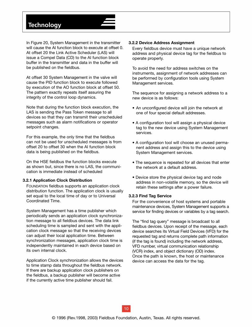
3.2.2 Device Address AssignmentEvery fieldbus device must have a unique networkaddress and physical device tag for the fieldbus tooperate properly.
To avoid the need for address switches on theinstruments, assignment of network addresses canbe performed by configuration tools using SystemManagement services.
The sequence for assigning a network address to anew device is as follows:
• An unconfigured device will join the network atone of four special default addresses.
• A configuration tool will assign a physical devicetag to the new device using System Managementservices.
• A configuration tool will choose an unused perma-nent address and assign this to the device usingSystem Management services.
• The sequence is repeated for all devices that enterthe network at a default address.
• Device store the physical device tag and nodeaddress in non-volatile memory, so the device willretain these settings after a power failure.
3.2.3 Find Tag ServiceFor the convenience of host systems and portablemaintenance devices, System Management supports aservice for finding devices or variables by a tag search.
The “find tag query” message is broadcast to allfieldbus devices. Upon receipt of the message, eachdevice searches its Virtual Field Devices (VFD) for therequested tag and returns complete path information(if the tag is found) including the network address,VFD number, virtual communication relationship(VCR) index, and object dictionary (OD) index.Once the path is known, the host or maintenancedevice can access the data for the tag.
© 1996 (Rev.1998, 2003) Fieldbus Foundation, Austin, Texas. All rights reserved.
10
Technology
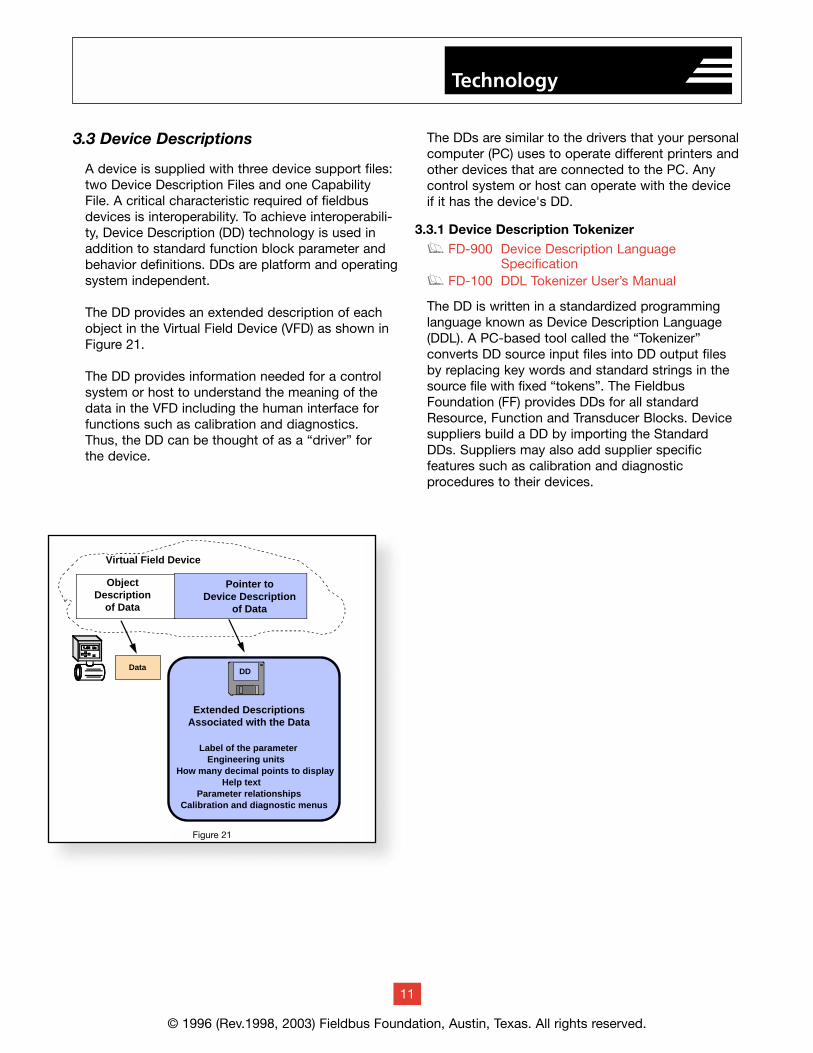
3.3 Device Descriptions
A device is supplied with three device support files:two Device Description Files and one CapabilityFile. A critical characteristic required of fieldbusdevices is interoperability. To achieve interoperabili-ty, Device Description (DD) technology is used inaddition to standard function block parameter andbehavior definitions. DDs are platform and operatingsystem independent.
The DD provides an extended description of eachobject in the Virtual Field Device (VFD) as shown inFigure 21.
The DD provides information needed for a controlsystem or host to understand the meaning of thedata in the VFD including the human interface forfunctions such as calibration and diagnostics. Thus, the DD can be thought of as a “driver” for the device.
The DDs are similar to the drivers that your personalcomputer (PC) uses to operate different printers andother devices that are connected to the PC. Anycontrol system or host can operate with the deviceif it has the device's DD.
3.3.1 Device Description Tokenizerg FD-900 Device Description Language
Specificationg FD-100 DDL Tokenizer User’s Manual
The DD is written in a standardized programminglanguage known as Device Description Language(DDL). A PC-based tool called the “Tokenizer” converts DD source input files into DD output filesby replacing key words and standard strings in thesource file with fixed “tokens”. The FieldbusFoundation (FF) provides DDs for all standardResource, Function and Transducer Blocks. Devicesuppliers build a DD by importing the StandardDDs. Suppliers may also add supplier specific features such as calibration and diagnostic procedures to their devices.
© 1996 (Rev.1998, 2003) Fieldbus Foundation, Austin, Texas. All rights reserved.
11
Technology
Virtual Field Device
Object Description
of Data
Pointer toDevice Description
of Data
Label of the parameterEngineering units
How many decimal points to displayHelp text
Parameter relationshipsCalibration and diagnostic menus
Data DD
Extended DescriptionsAssociated with the Data
Figure 41Figure 21
© 1996 (Rev.1998, 2003) Fieldbus Foundation, Austin, Texas. All rights reserved.
Device Descriptions for registered field devices canbe found on the Fieldbus Foundation’s website athttp://www.fieldbus.org.
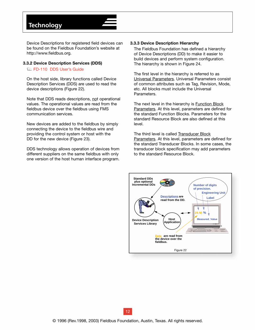
3.3.2 Device Description Services (DDS)g FD-110 DDS User’s Guide
On the host side, library functions called DeviceDescription Services (DDS) are used to read thedevice descriptions (Figure 22).
Note that DDS reads descriptions, not operationalvalues. The operational values are read from thefieldbus device over the fieldbus using FMS communication services.
New devices are added to the fieldbus by simplyconnecting the device to the fieldbus wire and providing the control system or host with the DD for the new device (Figure 23).
DDS technology allows operation of devices fromdifferent suppliers on the same fieldbus with onlyone version of the host human interface program.
3.3.3 Device Description HierarchyThe Fieldbus Foundation has defined a hierarchy of Device Descriptions (DD) to make it easier tobuild devices and perform system configuration.The hierarchy is shown in Figure 24.
The first level in the hierarchy is referred to asUniversal Parameters. Universal Parameters consistof common attributes such as Tag, Revision, Mode,etc. All blocks must include the UniversalParameters.
The next level in the hierarchy is Function BlockParameters. At this level, parameters are defined forthe standard Function Blocks. Parameters for thestandard Resource Block are also defined at thislevel.
The third level is called Transducer BlockParameters. At this level, parameters are defined forthe standard Transducer Blocks. In some cases, thetransducer block specification may add parametersto the standard Resource Block.
12
Technology
HostApplication
Device DescriptionServices Library
Standard DDsplus optional
Incremental DDs
Data are read fromthe device over thefieldbus.
Number of digits of precision.
Engineering Unit
Label
25.50
Measured_Value
%
Descriptions are read from the DD.
Figure 22
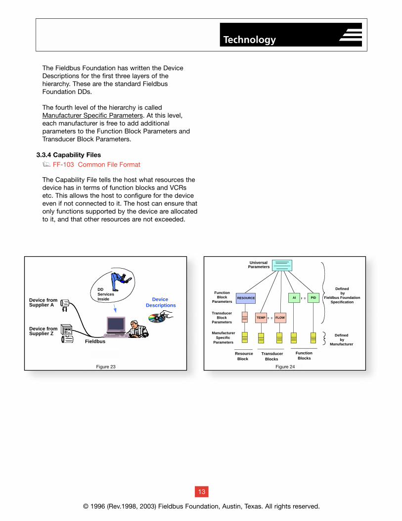
The Fieldbus Foundation has written the DeviceDescriptions for the first three layers of the hierarchy. These are the standard FieldbusFoundation DDs.
The fourth level of the hierarchy is calledManufacturer Specific Parameters. At this level,each manufacturer is free to add additional parameters to the Function Block Parameters andTransducer Block Parameters.
3.3.4 Capability Filesg FF-103 Common File Format
The Capability File tells the host what resources thedevice has in terms of function blocks and VCRsetc. This allows the host to configure for the deviceeven if not connected to it. The host can ensure thatonly functions supported by the device are allocatedto it, and that other resources are not exceeded.
© 1996 (Rev.1998, 2003) Fieldbus Foundation, Austin, Texas. All rights reserved.
13
Technology
Device Descriptions
Fieldbus
Device fromSupplier A
Device fromSupplier Z
DD ServicesInside
Figure 45
Defined by
Fieldbus FoundationSpecification
Defined by
Manufacturer
Figure 46
UniversalParameters
FunctionBlock
Parameters
ManufacturerSpecific
Parameters
Function Blocks
Transducer Blocks
Resource Block
AI PIDAI PIDRESOURCE
TransducerBlock
ParametersTEMP FLOW
Figure 23 Figure 24
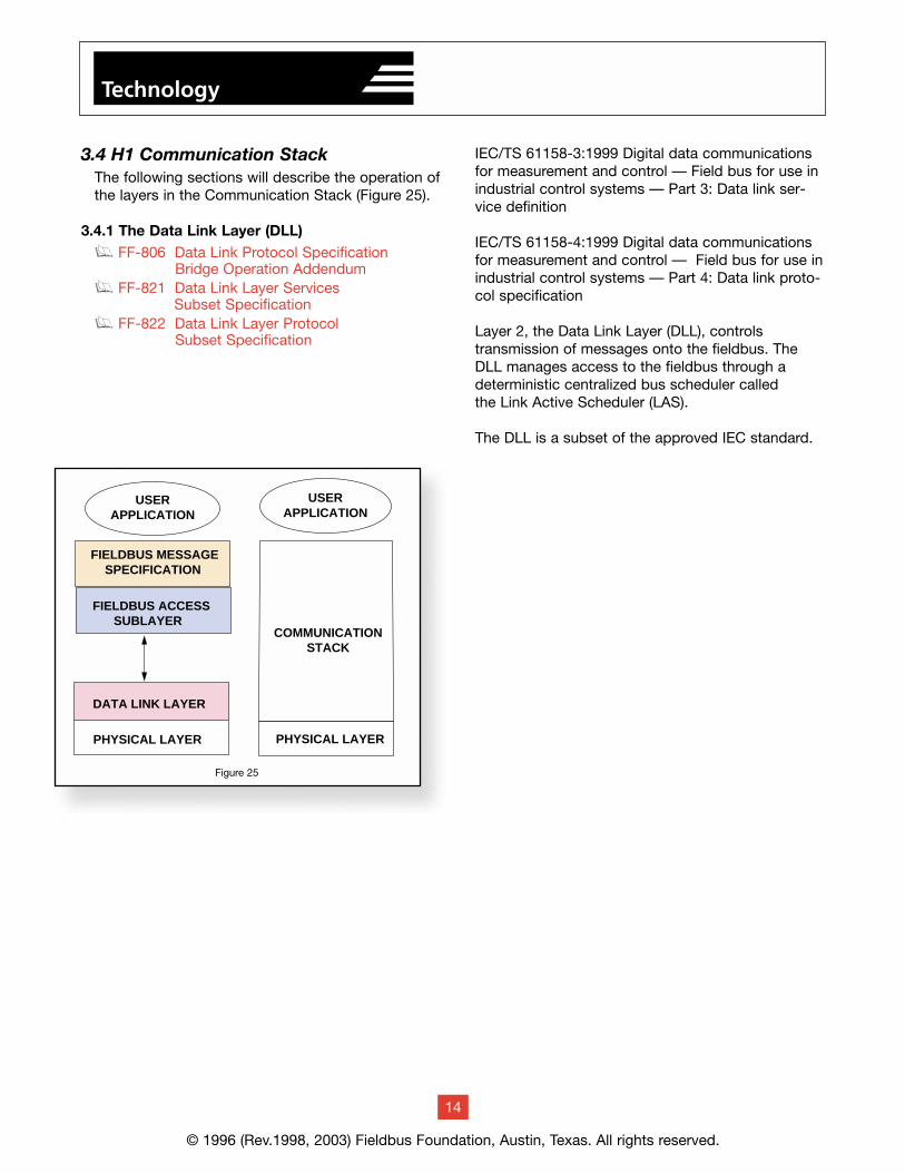
3.4 H1 Communication StackThe following sections will describe the operation ofthe layers in the Communication Stack (Figure 25).
3.4.1 The Data Link Layer (DLL)g FF-806 Data Link Protocol Specification
Bridge Operation Addendumg FF-821 Data Link Layer Services
Subset Specificationg FF-822 Data Link Layer Protocol
Subset Specification
IEC/TS 61158-3:1999 Digital data communicationsfor measurement and control — Field bus for use inindustrial control systems — Part 3: Data link ser-vice definition
IEC/TS 61158-4:1999 Digital data communicationsfor measurement and control — Field bus for use inindustrial control systems — Part 4: Data link proto-col specification
Layer 2, the Data Link Layer (DLL), controls transmission of messages onto the fieldbus. TheDLL manages access to the fieldbus through adeterministic centralized bus scheduler called the Link Active Scheduler (LAS).
The DLL is a subset of the approved IEC standard.
14
Technology
© 1996 (Rev.1998, 2003) Fieldbus Foundation, Austin, Texas. All rights reserved.
PHYSICAL LAYER
DATA LINK LAYER
FIELDBUS ACCESSSUBLAYER
FIELDBUS MESSAGESPECIFICATION
USERAPPLICATION
PHYSICAL LAYER
COMMUNICATIONSTACK
USERAPPLICATION
Figure 25
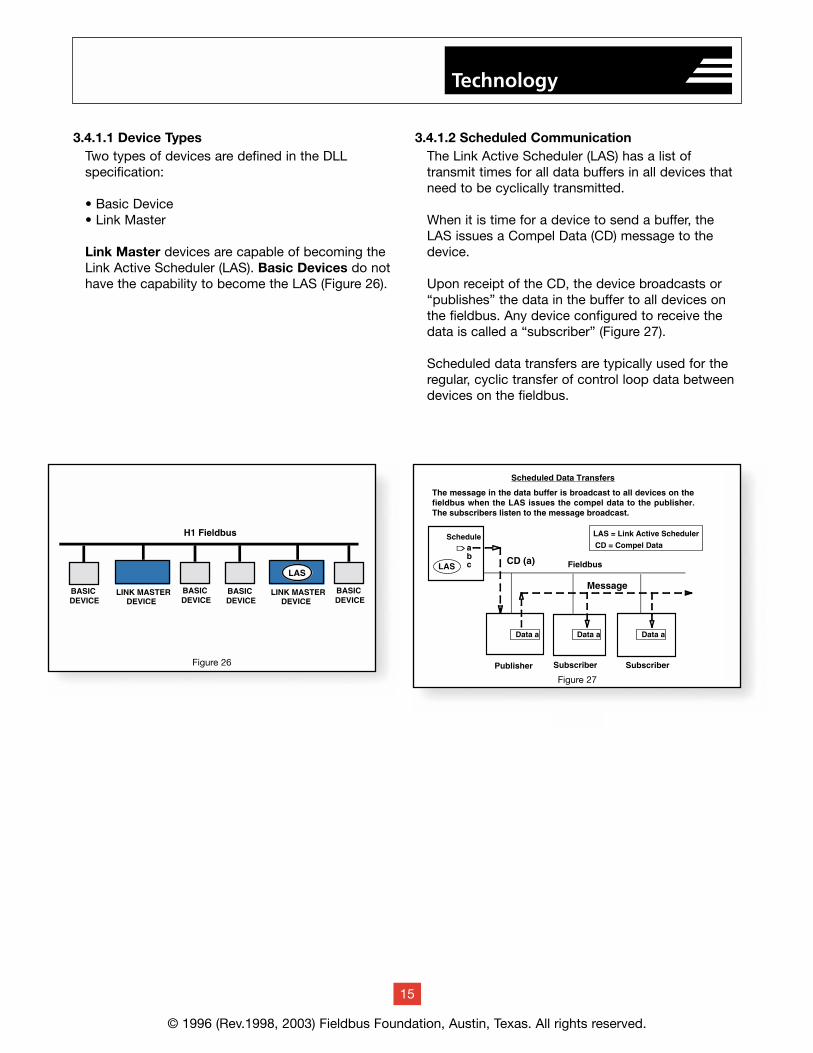
3.4.1.1 Device TypesTwo types of devices are defined in the DLL specification:
• Basic Device• Link Master
Link Master devices are capable of becoming theLink Active Scheduler (LAS). Basic Devices do nothave the capability to become the LAS (Figure 26).
3.4.1.2 Scheduled CommunicationThe Link Active Scheduler (LAS) has a list of transmit times for all data buffers in all devices thatneed to be cyclically transmitted.
When it is time for a device to send a buffer, theLAS issues a Compel Data (CD) message to thedevice.
Upon receipt of the CD, the device broadcasts or“publishes” the data in the buffer to all devices onthe fieldbus. Any device configured to receive thedata is called a “subscriber” (Figure 27).
Scheduled data transfers are typically used for theregular, cyclic transfer of control loop data betweendevices on the fieldbus.
Technology
© 1996 (Rev.1998, 2003) Fieldbus Foundation, Austin, Texas. All rights reserved.
15
Technology
Figure 26
Figure 27
Technology
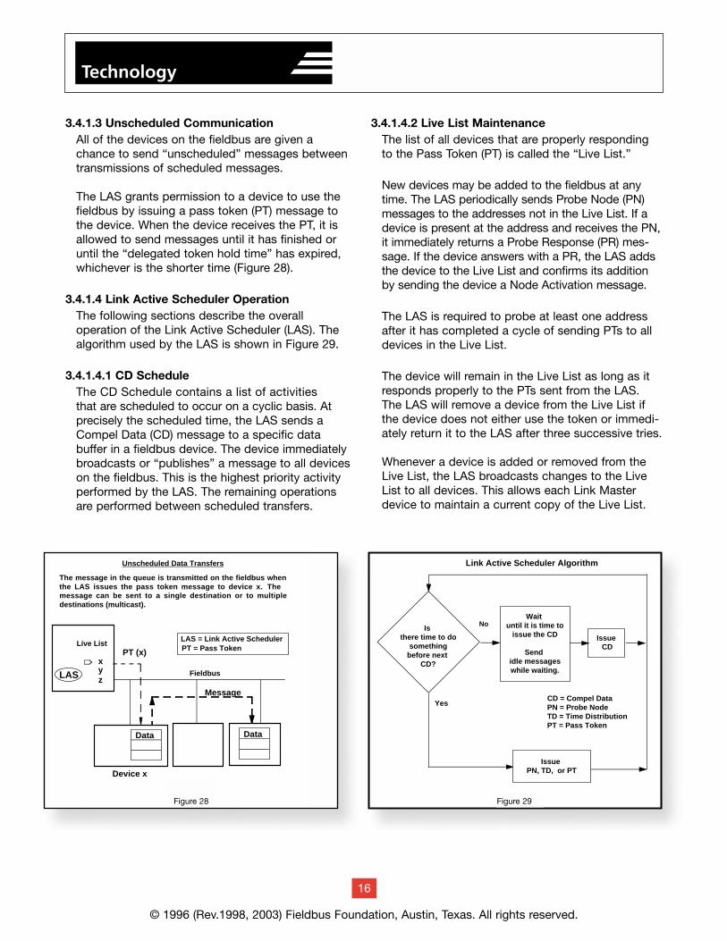
3.4.1.3 Unscheduled CommunicationAll of the devices on the fieldbus are given a chance to send “unscheduled” messages betweentransmissions of scheduled messages.
The LAS grants permission to a device to use thefieldbus by issuing a pass token (PT) message tothe device. When the device receives the PT, it isallowed to send messages until it has finished oruntil the “delegated token hold time” has expired,whichever is the shorter time (Figure 28).
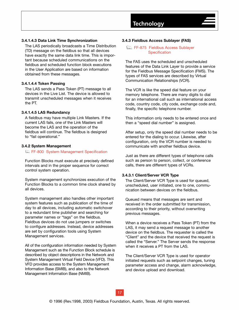
3.4.1.4 Link Active Scheduler OperationThe following sections describe the overall operation of the Link Active Scheduler (LAS). Thealgorithm used by the LAS is shown in Figure 29.
3.4.1.4.1 CD ScheduleThe CD Schedule contains a list of activities that are scheduled to occur on a cyclic basis. Atprecisely the scheduled time, the LAS sends aCompel Data (CD) message to a specific data buffer in a fieldbus device. The device immediatelybroadcasts or “publishes” a message to all deviceson the fieldbus. This is the highest priority activityperformed by the LAS. The remaining operations are performed between scheduled transfers.
3.4.1.4.2 Live List MaintenanceThe list of all devices that are properly respondingto the Pass Token (PT) is called the “Live List.”
New devices may be added to the fieldbus at anytime. The LAS periodically sends Probe Node (PN)messages to the addresses not in the Live List. If adevice is present at the address and receives the PN,it immediately returns a Probe Response (PR) mes-sage. If the device answers with a PR, the LAS addsthe device to the Live List and confirms its additionby sending the device a Node Activation message.
The LAS is required to probe at least one addressafter it has completed a cycle of sending PTs to alldevices in the Live List.
The device will remain in the Live List as long as itresponds properly to the PTs sent from the LAS.The LAS will remove a device from the Live List ifthe device does not either use the token or immedi-ately return it to the LAS after three successive tries.
Whenever a device is added or removed from theLive List, the LAS broadcasts changes to the LiveList to all devices. This allows each Link Masterdevice to maintain a current copy of the Live List.
© 1996 (Rev.1998, 2003) Fieldbus Foundation, Austin, Texas. All rights reserved.
16
Technology
Link Active Scheduler Algorithm
Is there time to do
somethingbefore next
CD?
No
Issue PN, TD, or PT
Wait until it is time to
issue the CD
Send idle messageswhile waiting.
Issue CD
YesCD = Compel DataPN = Probe NodeTD = Time DistributionPT = Pass Token
Figure 24Figure 29
LAS
Message
LAS = Link Active SchedulerPT = Pass Token
Data
Fieldbus
xyz
PT (x)
Data
Device x
Live List
Unscheduled Data Transfers
The message in the queue is transmitted on the fieldbus when the LAS issues the pass token message to device x. The message can be sent to a single destination or to multiple destinations (multicast).
Figure 23
Figure 28
3.4.1.4.3 Data Link Time SynchronizationThe LAS periodically broadcasts a Time Distribution(TD) message on the fieldbus so that all deviceshave exactly the same data link time. This is impor-tant because scheduled communications on thefieldbus and scheduled function block executions in the User Application are based on informationobtained from these messages.
3.4.1.4.4 Token PassingThe LAS sends a Pass Token (PT) message to alldevices in the Live List. The device is allowed totransmit unscheduled messages when it receivesthe PT.
3.4.1.4.5 LAS RedundancyA fieldbus may have multiple Link Masters. If thecurrent LAS fails, one of the Link Masters willbecome the LAS and the operation of the fieldbus will continue. The fieldbus is designed to “fail operational.”
3.4.2 System Managementg FF-800 System Management Specification
Function Blocks must execute at precisely definedintervals and in the proper sequence for correctcontrol system operation.
System management synchronizes execution of theFunction Blocks to a common time clock shared byall devices.
System management also handles other importantsystem features such as publication of the time ofday to all devices, including automatic switchover to a redundant time publisher and searching forparameter names or “tags” on the fieldbus. Fieldbus devices do not use jumpers or switches to configure addresses. Instead, device addressesare set by configuration tools using SystemManagement services.
All of the configuration information needed by SystemManagement such as the Function Block schedule isdescribed by object descriptions in the Network andSystem Management Virtual Field Device (VFD). ThisVFD provides access to the System ManagementInformation Base (SMIB), and also to the NetworkManagement Information Base (NMIB).
3.4.3 Fieldbus Access Sublayer (FAS)
FF-875 Fieldbus Access Sublayer Specification
The FAS uses the scheduled and unscheduled features of the Data Link Layer to provide a servicefor the Fieldbus Message Specification (FMS). Thetypes of FAS services are described by VirtualCommunication Relationships (VCR).
The VCR is like the speed dial feature on your memory telephone. There are many digits to dial for an international call such as international accesscode, country code, city code, exchange code and,finally, the specific telephone number.
This information only needs to be entered once andthen a “speed dial number” is assigned.
After setup, only the speed dial number needs to beentered for the dialing to occur. Likewise, afterconfiguration, only the VCR number is needed tocommunicate with another fieldbus device.
Just as there are different types of telephone callssuch as person to person, collect, or conferencecalls, there are different types of VCRs.
3.4.3.1 Client/Server VCR TypeThe Client/Server VCR Type is used for queued,unscheduled, user initiated, one to one, commu-nication between devices on the fieldbus.
Queued means that messages are sent andreceived in the order submitted for transmission,according to their priority, without overwriting previous messages.
When a device receives a Pass Token (PT) from theLAS, it may send a request message to anotherdevice on the fieldbus. The requester is called the“Client” and the device that received the request iscalled the “Server.” The Server sends the responsewhen it receives a PT from the LAS.
The Client/Server VCR Type is used for operator initiated requests such as setpoint changes, tuningparameter access and change, alarm acknowledge,and device upload and download.
g
© 1996 (Rev.1998, 2003) Fieldbus Foundation, Austin, Texas. All rights reserved.
17
Technology
3.4.3.2 Report Distribution VCR TypeThe Report Distribution VCR Type is used forqueued, unscheduled, user initiated, and one-to-many communications.
When a device with an event or a trend reportreceives a PT from the LAS, it sends its message to a “group address” defined for its VCR. Devicesthat are configured to listen for that VCR will receive the report.
The Report Distribution VCR Type is typically usedby fieldbus devices to send alarm notifications tothe operator consoles.
3.4.3.3 Publisher/Subscriber VCR TypeThe Publisher/Subscriber VCR Type is used forbuffered, one-to-many communications.
Buffered means that only the latest version of thedata is maintained within the network. New datacompletely overwrites previous data.
When a device receives the Compel Data (CD), thedevice will “Publish” or broadcast its message to alldevices on the fieldbus. Devices that wish to receivethe Published message are called “Subscribers.”
The CD may be scheduled in the LAS, or it may besent by Subscribers on an unscheduled basis. Anattribute of the VCR indicates which method is used.
The Publisher/Subscriber VCR Type is used by thefield devices for cyclic, scheduled, publishing ofUser Application function block input and outputssuch as Process Variable (PV) and Primary Output(OUT) on the fieldbus.
3.4.3.4 Summary of VCR Types (Figure 30)
3.4.4 Fieldbus Message Specification (FMS)g FF-870 Fieldbus Message Specification
Fieldbus Message Specification (FMS) servicesallow user applications to send messages to eachother across the fieldbus using a standard set ofmessage formats. FMS describes the communica-tion services, message formats, and protocolbehavior needed to build messages for the UserApplication (Figure 31).
Data that is communicated over the fieldbus isdescribed by an “object description.” Objectdescriptions are collected together in a structurecalled an “Object Dictionary” (OD), (Figure 32).
© 1996 (Rev.1998, 2003) Fieldbus Foundation, Austin, Texas. All rights reserved.
18
Technology
FIELDBUS
CommunicationServices
User Application
FieldbusDevice
User Application
FieldbusDevice
FMS FMS
FAS FASDLL
PHY
DLL
PHY
Object Dictionary
Object Description 1
Object Description 2
Object Description n
Index 1Index 0
Index 2
Index n
Figure 32
Figure 31
Used for Operator Messages
DATA LINK LAYER SERVICES
Used for Publishing Data
FIELDBUS ACCESS SUBLAYER SERVICES
Used forEvent Notification
andTrend ReportsSetpoint changes
Mode changesTuning changesUpload/DownloadAlarm ManagementAccess display viewsRemote diagnostics
Send process alarmsto operator consoles.
Send trend reportsto data historians.
Send transmitter PV to PID control block
and operator console.
Client/ServerVCR Type
Report DistributionVCR Type
Publisher/SubscriberVCR Type
Figure 30
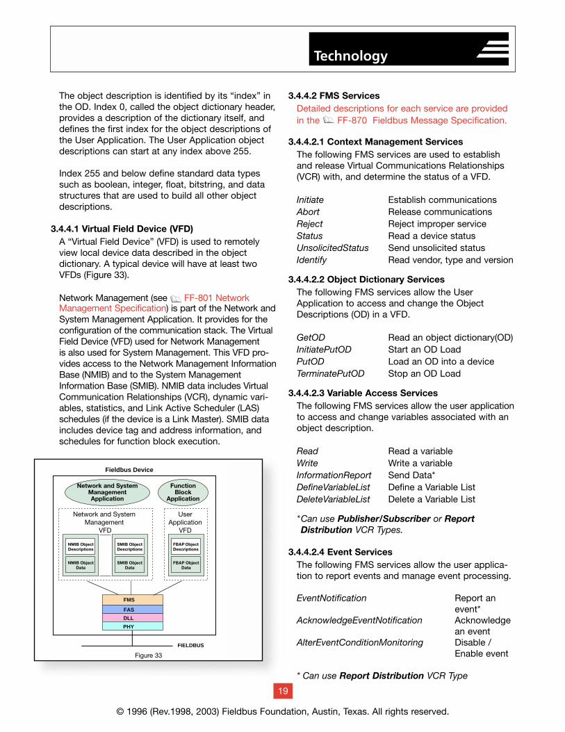
The object description is identified by its “index” inthe OD. Index 0, called the object dictionary header,provides a description of the dictionary itself, anddefines the first index for the object descriptions ofthe User Application. The User Application objectdescriptions can start at any index above 255.
Index 255 and below define standard data typessuch as boolean, integer, float, bitstring, and datastructures that are used to build all other objectdescriptions.
3.4.4.1 Virtual Field Device (VFD)A “Virtual Field Device” (VFD) is used to remotelyview local device data described in the object dictionary. A typical device will have at least twoVFDs (Figure 33).
Network Management (see g FF-801 NetworkManagement Specification) is part of the Network andSystem Management Application. It provides for theconfiguration of the communication stack. The VirtualField Device (VFD) used for Network Management is also used for System Management. This VFD pro-vides access to the Network Management InformationBase (NMIB) and to the System ManagementInformation Base (SMIB). NMIB data includes VirtualCommunication Relationships (VCR), dynamic vari-ables, statistics, and Link Active Scheduler (LAS)schedules (if the device is a Link Master). SMIB dataincludes device tag and address information, andschedules for function block execution.
System Management is described further in the UserApplication section.
3.4.4.2 Communication ServicesFMS communication services provide a standardizedway for user applications such as function blocks tocommunicate over the fieldbus. Specific FMS com-munication services are defined for each object type.
All of the FMS services can only use the Client/ServerVCR Type except as noted.
3.4.4.2 FMS ServicesDetailed descriptions for each service are providedin the g FF-870 Fieldbus Message Specification.
3.4.4.2.1 Context Management ServicesThe following FMS services are used to establishand release Virtual Communications Relationships(VCR) with, and determine the status of a VFD.
Initiate Establish communicationsAbort Release communicationsReject Reject improper serviceStatus Read a device statusUnsolicitedStatus Send unsolicited statusIdentify Read vendor, type and version
3.4.4.2.2 Object Dictionary ServicesThe following FMS services allow the UserApplication to access and change the ObjectDescriptions (OD) in a VFD.
GetOD Read an object dictionary(OD)InitiatePutOD Start an OD LoadPutOD Load an OD into a deviceTerminatePutOD Stop an OD Load
3.4.4.2.3 Variable Access ServicesThe following FMS services allow the user applicationto access and change variables associated with anobject description.
Read Read a variableWrite Write a variableInformationReport Send Data*DefineVariableList Define a Variable ListDeleteVariableList Delete a Variable List
*Can use Publisher/Subscriber or Report Distribution VCR Types.
3.4.4.2.4 Event ServicesThe following FMS services allow the user applica-tion to report events and manage event processing.
EventNotification Report an event*
AcknowledgeEventNotification Acknowledge an event
AlterEventConditionMonitoring Disable / Enable event
* Can use Report Distribution VCR Type
© 1996 (Rev.1998, 2003) Fieldbus Foundation, Austin, Texas. All rights reserved.
19
Technology
Figure 28
Fieldbus Device
FIELDBUS
FMS
FAS
DLL
PHY
NetworkManagementApplication
NetworkManagement
VFD
FunctionBlock
Application
UserApplication
VFD
SystemManagementApplication
SystemManagement
VFD
ObjectDescriptions
ObjectData
ObjectDescriptions
ObjectData
ObjectDescriptions
ObjectData
Figure 33
3.4.4.2.5 Upload/Download ServicesIt is often necessary to remotely upload or down-load data and programs over the fieldbus, especiallyfor more complex devices such as programmablelogic controllers.
To allow uploads and downloads using the FMS services, a “Domain” is used. A Domain representsa memory space in a device.
The following FMS services allow the UserApplication to upload and download a Domain in aremote device.
RequestDomainUpload Request Upload
InitiateUploadSequence Open Upload
UploadSegment Read Data from Device
TerminateUploadSequence Stop Upload
RequestDomainDownload Request Download
InitiateDownloadSequence Open Download
DownloadSegment Send Data to Device
TerminateDownloadSequence Stop Download
GenericInitiateDownloadSequence Open Download
GenericDownloadSegment Send Data to Device
GenericTerminateDownload
Sequence Stop Download
3.4.4.2.6 Program Invocation ServicesThe “Program Invocation” (PI) allows the executionof a program in one device to be controlled remotely.
A device could download a program into a Domain(see previous section) of another device using thedownload service and then remotely operate theprogram by issuing PI service requests. The statediagram for the PI is shown as an example of FMSprotocol behavior later in this document.
CreateProgramInvocation Create a program object
DeleteProgramInvocation Delete a program object
Start Start a programStop Stop a programResume Resume program
executionReset Reset the programKill Remove the
program
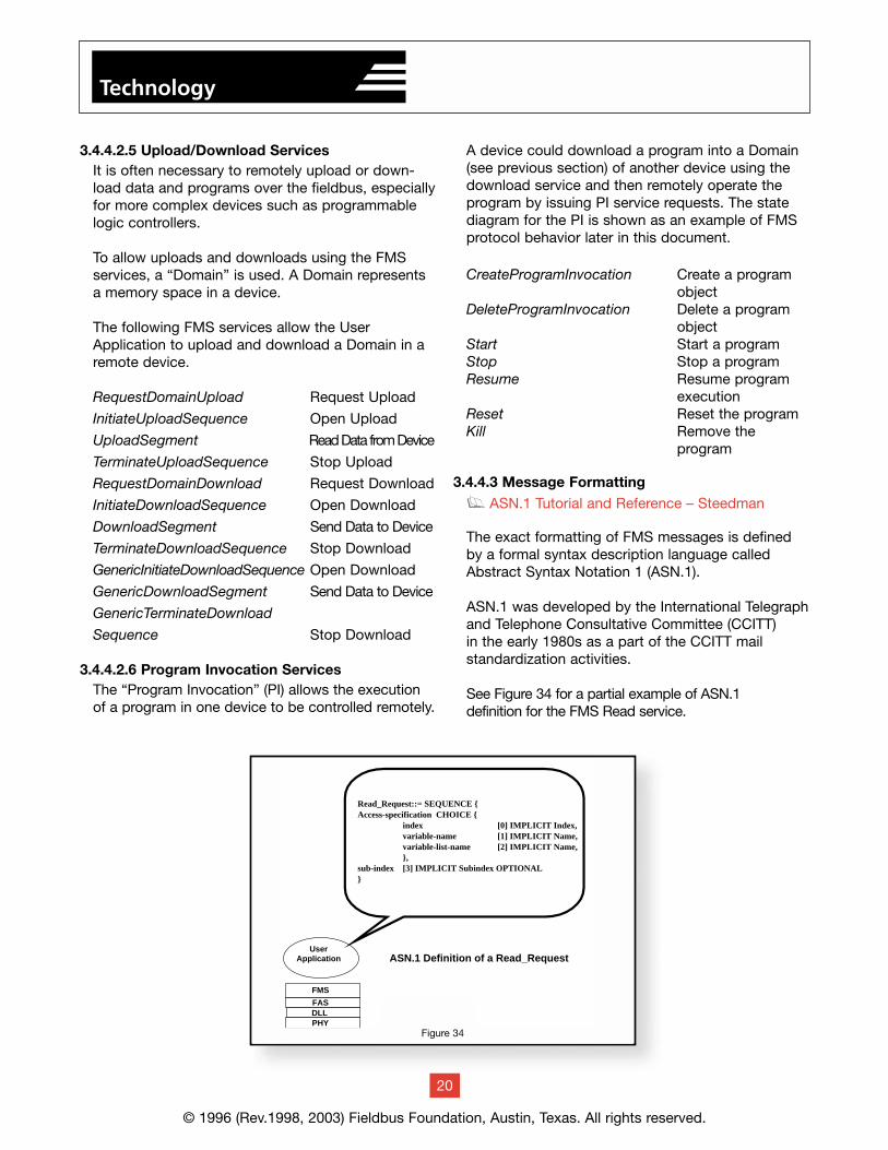
3.4.4.3 Message Formattingg ASN.1 Tutorial and Reference – Steedman
The exact formatting of FMS messages is definedby a formal syntax description language calledAbstract Syntax Notation 1 (ASN.1).
ASN.1 was developed by the International Telegraphand Telephone Consultative Committee (CCITT) in the early 1980s as a part of the CCITT mail standardization activities.
See Figure 34 for a partial example of ASN.1 definition for the FMS Read service.
20
© 1996 (Rev.1998, 2003) Fieldbus Foundation, Austin, Texas. All rights reserved.
Technology
ASN.1 Definition of a Read_Request
Read_Request::= SEQUENCE {Access-specification CHOICE {
index [0] IMPLICIT Index,variable-name [1] IMPLICIT Name,variable-list-name [2] IMPLICIT Name,},
sub-index [3] IMPLICIT Subindex OPTIONAL}
Figure 29
User Application
FMS
FASDLLPHY
Figure 34
The previous example states that the items Access-specification and sub-index occur in SEQUENCE in themessage.
The Access-specification is a CHOICE of usingeither an index or a name to access a variable.
The sub-index is OPTIONAL. It is used only toselect an individual element of an array or recordvariable.
The numbers in the brackets are the actual encod-ing numbers that are used to identify the fields in anencoded message.
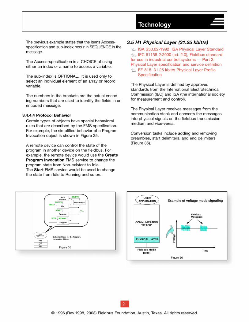
3.4.4.4 Protocol BehaviorCertain types of objects have special behavioralrules that are described by the FMS specification.For example, the simplified behavior of a ProgramInvocation object is shown in Figure 35.
A remote device can control the state of the program in another device on the fieldbus. Forexample, the remote device would use the CreateProgram Invocation FMS service to change theprogram state from Non-existent to Idle. The Start FMS service would be used to changethe state from Idle to Running and so on.
3.5 H1 Physical Layer (31.25 kbit/s)ISA S50.02-1992 ISA Physical Layer StandardIEC 61158-2:2000 (ed. 2.0), Fieldbus standard
for use in industrial control systems — Part 2:Physical Layer specification and service definition
FF-816 31.25 kbit/s Physical Layer Profile Specification
The Physical Layer is defined by approved standards from the International ElectrotechnicalCommission (IEC) and ISA (the international societyfor measurement and control).
The Physical Layer receives messages from the communication stack and converts the messagesinto physical signals on the fieldbus transmissionmedium and vice-versa.
Conversion tasks include adding and removing preambles, start delimiters, and end delimiters(Figure 36).
g
g
g
© 1996 (Rev.1998, 2003) Fieldbus Foundation, Austin, Texas. All rights reserved.
21
Technology
Non-existent
Idle
Running
Stopped
Unrunnable
DELETE
KILL
CREATE
START
STOP RESUME
RESET
User Application
FMS
FASDLLPHY
Behavior Rules for the ProgramInvocation Object.
Figure 30Figure 35
1 11 1
Vo
ltag
e
Time
FieldbusMessages
Figure 11
Fieldbus Media(Wire)
PHYSICAL LAYER
COMMUNICATION“STACK”
USERAPPLICATION Example of voltage mode signaling
Figure 36
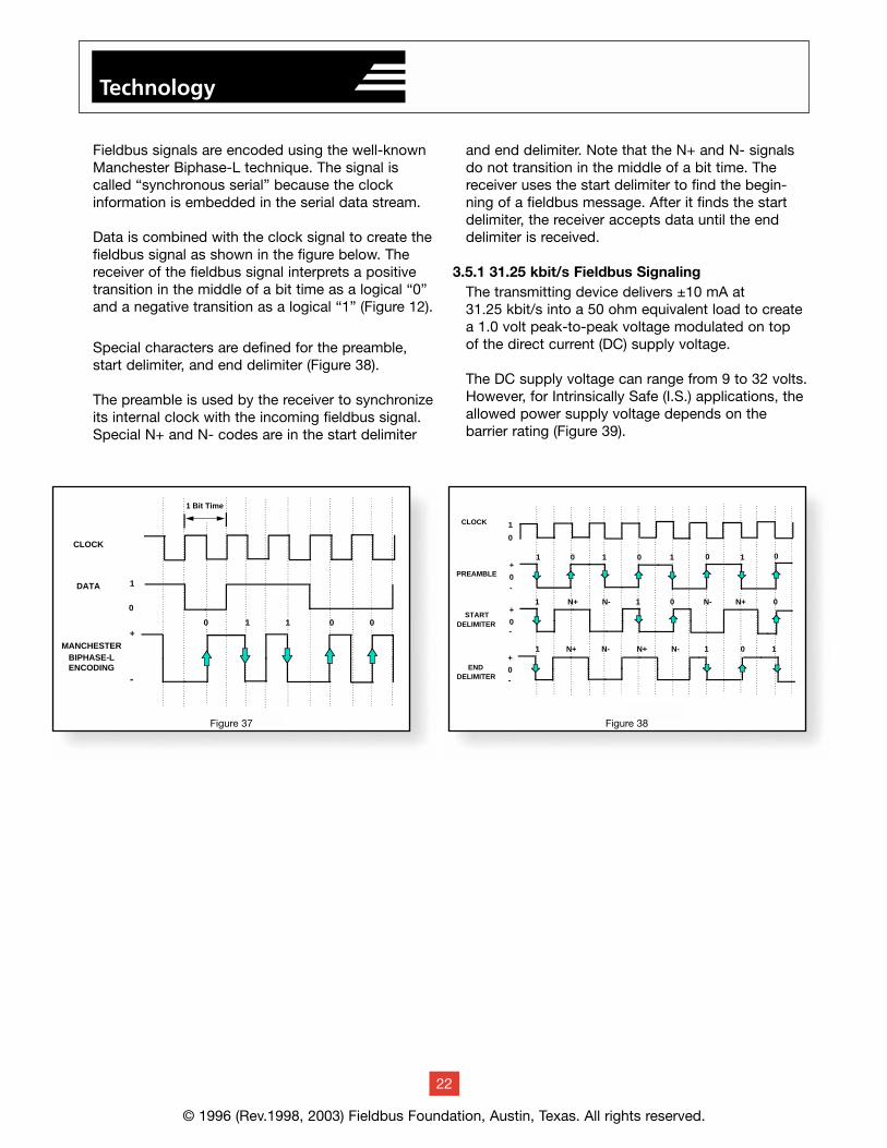
Fieldbus signals are encoded using the well-knownManchester Biphase-L technique. The signal iscalled “synchronous serial” because the clock information is embedded in the serial data stream.
Data is combined with the clock signal to create thefieldbus signal as shown in the figure below. Thereceiver of the fieldbus signal interprets a positivetransition in the middle of a bit time as a logical “0”and a negative transition as a logical “1” (Figure 12).
Special characters are defined for the preamble,start delimiter, and end delimiter (Figure 38).
The preamble is used by the receiver to synchronizeits internal clock with the incoming fieldbus signal.Special N+ and N- codes are in the start delimiter
and end delimiter. Note that the N+ and N- signalsdo not transition in the middle of a bit time. Thereceiver uses the start delimiter to find the begin-ning of a fieldbus message. After it finds the startdelimiter, the receiver accepts data until the enddelimiter is received.
3.5.1 31.25 kbit/s Fieldbus SignalingThe transmitting device delivers ±10 mA at 31.25 kbit/s into a 50 ohm equivalent load to createa 1.0 volt peak-to-peak voltage modulated on top of the direct current (DC) supply voltage.
The DC supply voltage can range from 9 to 32 volts.However, for Intrinsically Safe (I.S.) applications, theallowed power supply voltage depends on the barrier rating (Figure 39).
© 1996 (Rev.1998, 2003) Fieldbus Foundation, Austin, Texas. All rights reserved.
22
Technology
+
-
1
0
DATA
CLOCK
MANCHESTERBIPHASE-LENCODING
1 Bit Time
0 01 1 0
Figure 12
PREAMBLE
STARTDELIMITER
ENDDELIMITER
CLOCK
+
0-
0 11 0 01
+
0
N+ 0N- N-1
1
N+ 0
+
0-
N+ N-1 N+ N- 1 0 1
-
1
0
1
0
Figure 13
Figure 38Figure 37
31.25 kbit/s devices can be powered directly fromthe fieldbus and can operate on wiring previouslyused for 4-20 mA devices.
The 31.25 kbit/s fieldbus also supports I.S. fieldbuses with bus powered devices. To accom-plish this, an I.S. barrier is placed between thepower supply in the safe area and the I.S. device in the hazardous area.
To address Intrinsic Safety applications, theFieldbus Foundation supports using either the traditional Entity model or the newer FieldbusIntrinsically Safe Concept (FISCO). The mixing of theEntity model with the FISCO approach in the prepa-ration of a system design is not recommended.
3.5.2 31.25 kbit/s Fieldbus Wiringg AG-140 31.25 kbit/s Wiring and Installation Guide
AG-163 31.25 kbit/s Intrinsically Safe Systems Application GuideAG-165 Fieldbus Installation and Planning Guide
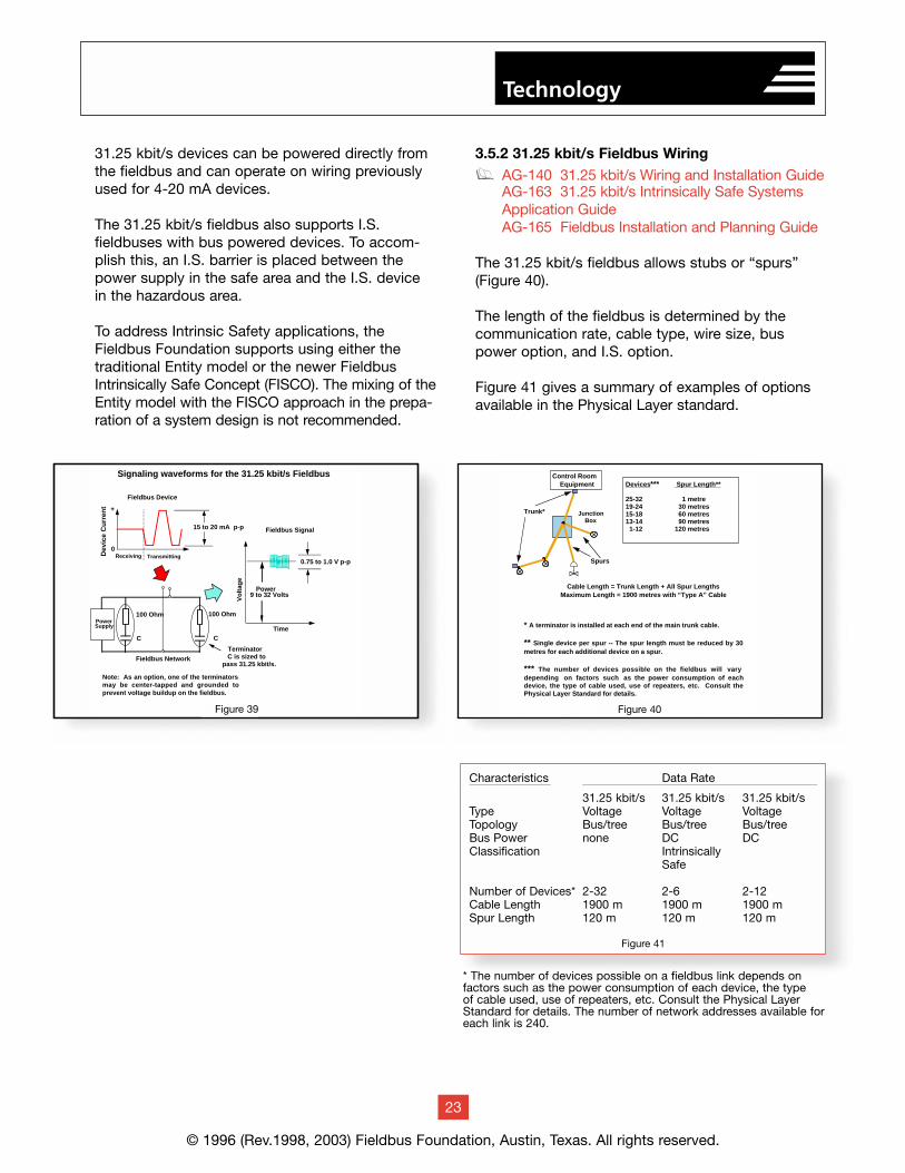
The 31.25 kbit/s fieldbus allows stubs or “spurs”(Figure 40).
The length of the fieldbus is determined by thecommunication rate, cable type, wire size, buspower option, and I.S. option.
Figure 41 gives a summary of examples of optionsavailable in the Physical Layer standard.
© 1996 (Rev.1998, 2003) Fieldbus Foundation, Austin, Texas. All rights reserved.
23
Technology
* A terminator is installed at each end of the main trunk cable.
** Single device per spur -- The spur length must be reduced by 30 metres for each additional device on a spur.
*** The number of devices possible on the fieldbus will vary depending on factors such as the power consumption of each device, the type of cable used, use of repeaters, etc. Consult the Physical Layer Standard for details.
Devices*** Spur Length**
25-32 1 metre19-24 30 metres15-18 60 metres13-14 90 metres 1-12 120 metres
Trunk*
Spurs
Control RoomEquipment
JunctionBox
Cable Length = Trunk Length + All Spur LengthsMaximum Length = 1900 metres with “Type A” Cable
Figure 15
Dev
ice
Cu
rren
t
Vo
ltag
e
Time
Power9 to 32 Volts
0.75 to 1.0 V p-p
100 OhmPowerSupply
100 Ohm
+
0Receiving Transmitting
Fieldbus Device
Fieldbus Network
Fieldbus Signal
TerminatorC is sized to
pass 31.25 kbit/s.
15 to 20 mA p-p
C C
Signaling waveforms for the 31.25 kbit/s Fieldbus
Note: As an option, one of the terminators may be center-tapped and grounded to prevent voltage buildup on the fieldbus.
Figure 14Figure 39 Figure 40
Characteristics Data Rate
31.25 kbit/s 31.25 kbit/s 31.25 kbit/sType Voltage Voltage VoltageTopology Bus/tree Bus/tree Bus/treeBus Power none DC DCClassification Intrinsically
Safe
Number of Devices* 2-32 2-6 2-12Cable Length 1900 m 1900 m 1900 mSpur Length 120 m 120 m 120 m
Figure 41
* The number of devices possible on a fieldbus link depends onfactors such as the power consumption of each device, the type of cable used, use of repeaters, etc. Consult the Physical LayerStandard for details. The number of network addresses available foreach link is 240.
3.6 HSE Communication Stack
g FF-581 System Architectureg FF-586 Ethernet Presenceg FF-588 Field Device Access (FDA) Agentg FF-589 HSE System Managementg FF-803 HSE Network Management
Most Ethernet-based protocols are not fully openbecause part of the “stack” is proprietary. The lackof higher-level standards has prevented easy inte-gration of other subsystems of the plant. The HSEstandard includes the application and user layers,thereby making it a completely open protocol.
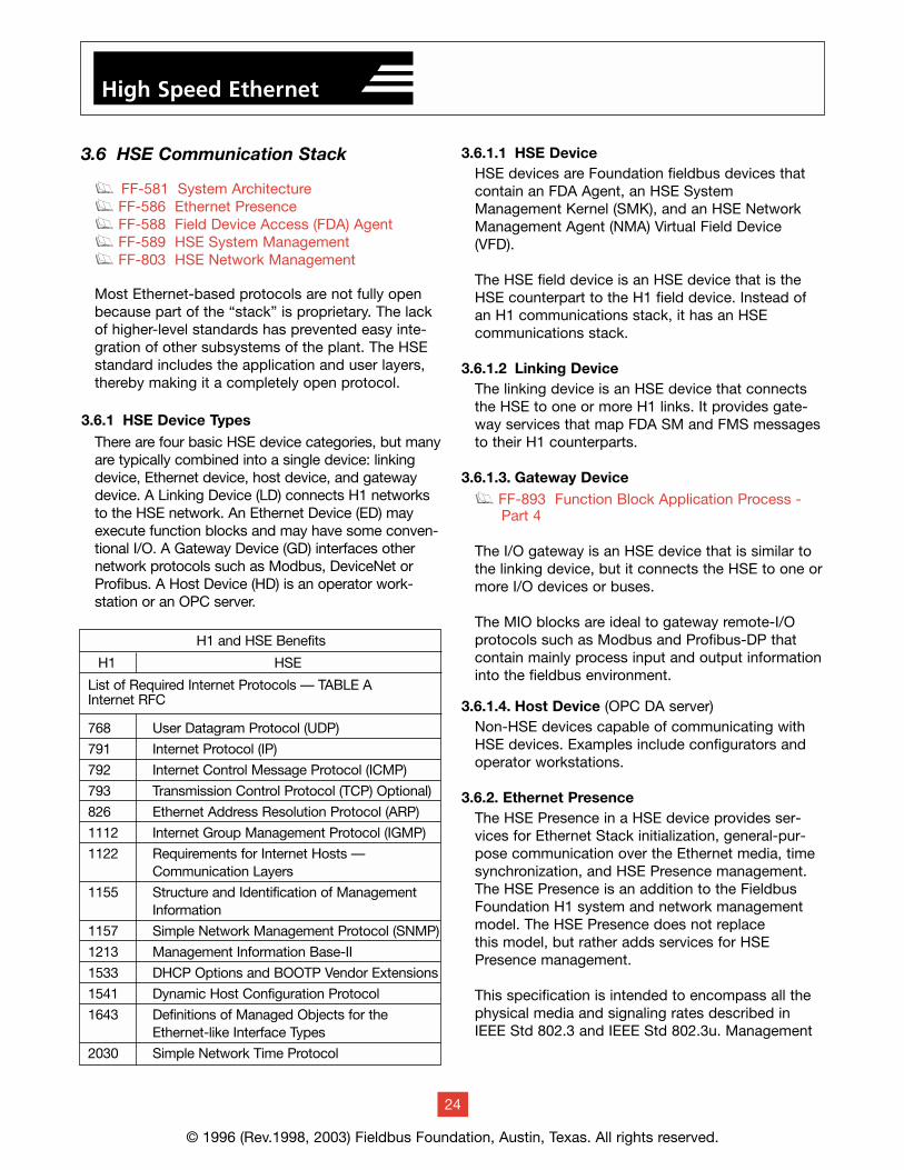
3.6.1 HSE Device TypesThere are four basic HSE device categories, but manyare typically combined into a single device: linkingdevice, Ethernet device, host device, and gatewaydevice. A Linking Device (LD) connects H1 networksto the HSE network. An Ethernet Device (ED) mayexecute function blocks and may have some conven-tional I/O. A Gateway Device (GD) interfaces othernetwork protocols such as Modbus, DeviceNet orProfibus. A Host Device (HD) is an operator work-station or an OPC server.
3.6.1.1 HSE DeviceHSE devices are Foundation fieldbus devices thatcontain an FDA Agent, an HSE SystemManagement Kernel (SMK), and an HSE NetworkManagement Agent (NMA) Virtual Field Device(VFD).
The HSE field device is an HSE device that is theHSE counterpart to the H1 field device. Instead ofan H1 communications stack, it has an HSE communications stack.
3.6.1.2 Linking DeviceThe linking device is an HSE device that connectsthe HSE to one or more H1 links. It provides gate-way services that map FDA SM and FMS messagesto their H1 counterparts.
3.6.1.3. Gateway Deviceg FF-893 Function Block Application Process -
Part 4
The I/O gateway is an HSE device that is similar tothe linking device, but it connects the HSE to one ormore I/O devices or buses.
The MIO blocks are ideal to gateway remote-I/Oprotocols such as Modbus and Profibus-DP thatcontain mainly process input and output informationinto the fieldbus environment.
3.6.1.4. Host Device (OPC DA server)Non-HSE devices capable of communicating withHSE devices. Examples include configurators andoperator workstations.
3.6.2. Ethernet PresenceThe HSE Presence in a HSE device provides ser-vices for Ethernet Stack initialization, general-pur-pose communication over the Ethernet media, timesynchronization, and HSE Presence management.The HSE Presence is an addition to the FieldbusFoundation H1 system and network managementmodel. The HSE Presence does not replace this model, but rather adds services for HSEPresence management.
This specification is intended to encompass all thephysical media and signaling rates described inIEEE Std 802.3 and IEEE Std 802.3u. Management
© 1996 (Rev.1998, 2003) Fieldbus Foundation, Austin, Texas. All rights reserved.
24
High Speed Ethernet
List of Required Internet Protocols — TABLE AInternet RFC
768 User Datagram Protocol (UDP)
791 Internet Protocol (IP)
792 Internet Control Message Protocol (ICMP)
793 Transmission Control Protocol (TCP) Optional)
826 Ethernet Address Resolution Protocol (ARP)
1112 Internet Group Management Protocol (IGMP)
1122 Requirements for Internet Hosts — Communication Layers
1155 Structure and Identification of Management Information
1157 Simple Network Management Protocol (SNMP)
1213 Management Information Base-II
1533 DHCP Options and BOOTP Vendor Extensions
1541 Dynamic Host Configuration Protocol
1643 Definitions of Managed Objects for the Ethernet-like Interface Types
2030 Simple Network Time Protocol
H1 HSE
H1 and HSE Benefits
of the HSE Presence is employing SNMP augment-ed to support Fieldbus Foundation unique EthernetStack parameters.
The universal set of protocols which may be includ-ed in a given implementation of HSE Presence isidentified in Table A.
3.6.3 Field Device Access (FDA)The FDA Agent has the following objectives:• Convey System Management (SM) services overUDP and Fieldbus Message Specification (FMS) services over UDP/TCP. This allows HSE and H1 fielddevices, conventional I/O devices, and non-FF I/Odevices to be connected to the HSE through a linkingor a gateway device.• Republish H1 data from linking devices that do notsupport H1 bridging. This allows linking devices to beconstructed from multiple standalone H1 interfacesinstead of using an H1 bridge.• Send and receive LAN redundancy messages tosupport redundancy of HSE interfaces in devices.
The FDA Agent allows control systems to operateover the HSE and/or through Linking Devices and itenables remote applications to access field devices ofany type across UDP/TCP using a common interface.
3.6.4 HSE System ManagementSystem management is the activity that integratesdevices on an HSE network into a coherent communi-cation system.
The following functions are supported:• Each device has a unique, permanent identity and a system-specific configured name.• Devices maintain version control information.• Devices respond to requests to locate objects,including the device itself.• Time is distributed to all devices on the network.• Function block schedules are used to start functionblocks.• Devices are added and removed from the networkwithout affecting other devices on the network.
3.6.5 HSE Network ManagementHSE Network Management permits HSE host sys-tems to conduct management operations over theHSE network with their associated devices with anHSE interface.
The following capabilities are provided by networkmanagement:• Configuring the H1 Bridge, which performs dataforwarding and republishing between H1 interfaces• Loading the HSE Session List or single entries inthis list. An HSE Session Endpoint represents a logicalcommunication channel between two or more HSEdevices.• Loading the HSE VCR List or single entries in thislist. An HSE VCR is a communication relationshipused for accessing VFDs across the HSE.• Performance Monitoring through the collection ofstatistics for Session Endpoints, HSE VCRs, and theH1 Bridge.• Fault Detection Monitoring.
3.7 Redundancy
g FF-593 High Speed Ethernet Redundancy
For use in factory and process automation, Ethernethas to be made industrial strength. FOUNDATION
fieldbus HSE is based on Ethernet and is used at the host-level of the control system. The host-levelnetwork ties the whole system together linking thevarious subsystems to the host. Thus, the visibility ofhundreds and perhaps thousands of loops dependson the host-level network as does any intra-area control loops. A complete failure could result in heavylosses. High availability for the host-level network istherefore paramount. HSE is the only open, Ethernet-based protocol to address the need for round-the-clock availability of network and devices. Becausedevice and port redundancy requires interoperabilitybeyond Ethernet and IP, other Ethernet solutions donot support it. HSE is the first standard protocol tooffer functionality to select which device in a redun-dant pair and which one of redundant ports that atransmitting device should address. Exchange ofredundancy management information is part of thestandard protocol.
HSE is built on standard Ethernet, originally a technol-ogy for the office environment. However, industrialgrade hardware is available and HSE has a number of functions built in to insure fault tolerance. The modern form of Ethernet uses UTP (UnshieldedTwisted Pair) wiring using a hub-based star topologyin which there is only one device per wire segment.
© 1996 (Rev.1998, 2003) Fieldbus Foundation, Austin, Texas. All rights reserved.
25
High Speed Ethernet
Therefore, devices can be disconnected and connect-ed without disrupting other devices and any wire faultonly affects a single device (i.e., the impact of a faultis reduced somewhat).
A shared hub is a multiple port repeater that joins several segments into a single network. A switchedhub is a multiple port bridge that joins several net-works together. Fiber optic media can be employed to increase tolerance towards electrical noise andground potential differences further increasing therobustness of the system. Industrial grade hubs withredundant power supplies, wide temperature ranges,rugged enclosures, etc., are available for use in atough plant environment.
3.7.1 Need for Host-Level RedundancyThe shutdown of a plant is extremely disruptive and downtime means heavy losses. At the host-level the network and devices are shared betweenmany loops, making these parts very critical to theoperation of the plant. If the host-level network isnot functioning the operators would be unable tomonitor and supervise the plant and, therefore,many loops would have to be shut down. The host-level network is also used for intra-area controlloops that would have to be shut down. Unlike thefield-level where high availability is achieved by distributing functionality thereby isolating faults to a small sector, at the rather centralized host-levelredundancy is instead used to achieve high availability. Any Ethernet network can use mediaredundancy to achieve some measure of increasedavailability, but HSE also supports complete deviceand networking redundancy.
3.7.2 Media RedundancyAny Ethernet device even with just a single port canhave simple media redundancy using some form ofport “splitter”. Splitters are implemented in differentways but all work in the same basic fashion. A single port is split in two, connecting devicestogether in a circle providing alternate communica-tion paths. If communication in one direction is notpossible, communication is routed the other way(i.e., the network is “self-healing”). The switchovertime is very short. Recovery time is much fasterthan the traditional spanning tree algorithm, andthus operations will continue without any loss ofdata. A splitter may either be a transceiver handlinga single port requiring one at every node, or may beimplemented between hubs in a ring topology.
Media redundancy works only on the physical layerand is therefore independent of protocol used.
Some solutions require a central redundancy management device that may be an Achilles heel,whereas other solutions have the redundancy management built into the hubs. Very often themedia redundancy ring is implemented using fiberoptics. The ring is not a standard Ethernet topologyand the special splitting hubs and transceivers usually use standard media but employ proprietarymechanisms to manage the switchover. Therefore,all the splitters in the ring have to come from thesame manufacturer.
Simple media redundancy may be sufficient forsome applications, but not all. For example, someapplications combine media redundancy with fully duplicated networks and linking devices.
3.7.3 Complete Network RedundancyThe HSE protocol goes further than simple mediaredundancy. Special integrity-checking diagnosticsand redundancy management part of the HSE pro-tocol in each device enables use of two completelyindependent networks, redundant communicationports, and also redundant device pairs. All redun-dant Ethernet device pairs and the workstations are connected to both Ethernet buses. When a singleunit has two ports these are named “A” and “B”.The switchover is totally bumpless and transparent.The redundancy scheme leaves several deviceoptions open (Figure 45), but they are all compatiblewith each other, e.g.:
• Redundant device pair where primary and secondary have one port each
• Redundant device pair where primary and secondary have two ports each
• Single device that has two ports
All parts of the network have redundancy, includingthe hubs (i.e. two independent networks ensuringthat communication can continue even if one network fails). This means that the network can sustain multiple faults but still continue to function.Thus the networking is extremely reliable, minimiz-ing loss of data and unnecessary shutdowns.
The philosophy of the HSE redundancy is one of“operational transparency and diagnostic visibility”.
© 1996 (Rev.1998, 2003) Fieldbus Foundation, Austin, Texas. All rights reserved.
26
High Speed Ethernet
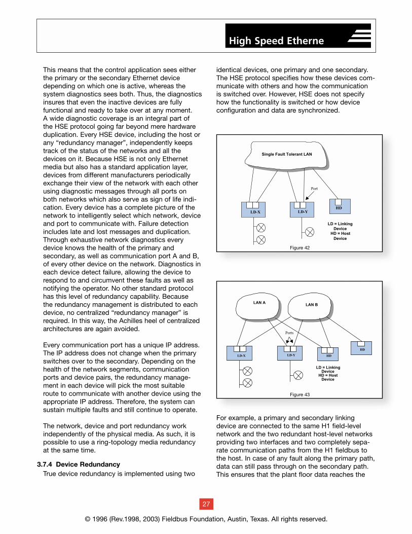
This means that the control application sees eitherthe primary or the secondary Ethernet devicedepending on which one is active, whereas the system diagnostics sees both. Thus, the diagnosticsinsures that even the inactive devices are fully functional and ready to take over at any moment. A wide diagnostic coverage is an integral part of the HSE protocol going far beyond mere hardwareduplication. Every HSE device, including the host orany “redundancy manager”, independently keepstrack of the status of the networks and all thedevices on it. Because HSE is not only Ethernetmedia but also has a standard application layer,devices from different manufacturers periodicallyexchange their view of the network with each otherusing diagnostic messages through all ports onboth networks which also serve as sign of life indi-cation. Every device has a complete picture of thenetwork to intelligently select which network, deviceand port to communicate with. Failure detectionincludes late and lost messages and duplication.Through exhaustive network diagnostics everydevice knows the health of the primary and secondary, as well as communication port A and B,of every other device on the network. Diagnostics ineach device detect failure, allowing the device torespond to and circumvent these faults as well asnotifying the operator. No other standard protocolhas this level of redundancy capability. Because the redundancy management is distributed to eachdevice, no centralized “redundancy manager” isrequired. In this way, the Achilles heel of centralizedarchitectures are again avoided.
Every communication port has a unique IP address.The IP address does not change when the primaryswitches over to the secondary. Depending on thehealth of the network segments, communicationports and device pairs, the redundancy manage-ment in each device will pick the most suitableroute to communicate with another device using theappropriate IP address. Therefore, the system cansustain multiple faults and still continue to operate.
The network, device and port redundancy workindependently of the physical media. As such, it ispossible to use a ring-topology media redundancyat the same time.
3.7.4 Device RedundancyTrue device redundancy is implemented using two
identical devices, one primary and one secondary.The HSE protocol specifies how these devices com-municate with others and how the communication is switched over. However, HSE does not specifyhow the functionality is switched or how deviceconfiguration and data are synchronized.
For example, a primary and secondary linkingdevice are connected to the same H1 field-level network and the two redundant host-level networksproviding two interfaces and two completely sepa-rate communication paths from the H1 fieldbus tothe host. In case of any fault along the primary path,data can still pass through on the secondary path.This ensures that the plant floor data reaches the
© 1996 (Rev.1998, 2003) Fieldbus Foundation, Austin, Texas. All rights reserved.
27
High Speed Etherne
LD = LinkingDevice
HD = HostDevice
LD-YLD-X
Single Fault Tolerant LAN
HD
Port
Figure 42
HD
LD = LinkingDevice
HD = HostDevice
LD-YLD-X
LAN A LAN B
Ports
HD
Figure 43
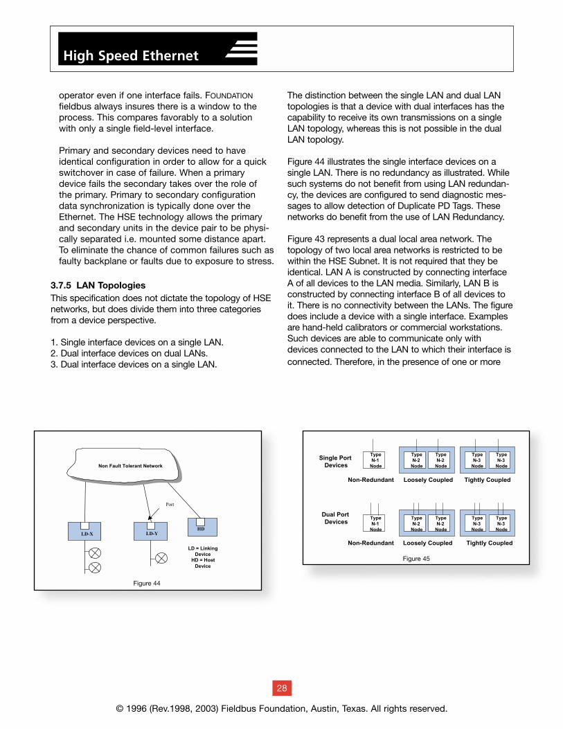
operator even if one interface fails. FOUNDATION
fieldbus always insures there is a window to theprocess. This compares favorably to a solution with only a single field-level interface.
Primary and secondary devices need to have identical configuration in order to allow for a quickswitchover in case of failure. When a primary device fails the secondary takes over the role of the primary. Primary to secondary configurationdata synchronization is typically done over theEthernet. The HSE technology allows the primaryand secondary units in the device pair to be physi-cally separated i.e. mounted some distance apart.To eliminate the chance of common failures such asfaulty backplane or faults due to exposure to stress.
3.7.5 LAN TopologiesThis specification does not dictate the topology of HSEnetworks, but does divide them into three categoriesfrom a device perspective.
1. Single interface devices on a single LAN.2. Dual interface devices on dual LANs.3. Dual interface devices on a single LAN.
The distinction between the single LAN and dual LANtopologies is that a device with dual interfaces has thecapability to receive its own transmissions on a singleLAN topology, whereas this is not possible in the dualLAN topology.
Figure 44 illustrates the single interface devices on asingle LAN. There is no redundancy as illustrated. Whilesuch systems do not benefit from using LAN redundan-cy, the devices are configured to send diagnostic mes-sages to allow detection of Duplicate PD Tags. Thesenetworks do benefit from the use of LAN Redundancy.
Figure 43 represents a dual local area network. Thetopology of two local area networks is restricted to bewithin the HSE Subnet. It is not required that they beidentical. LAN A is constructed by connecting interfaceA of all devices to the LAN media. Similarly, LAN B isconstructed by connecting interface B of all devices toit. There is no connectivity between the LANs. The figuredoes include a device with a single interface. Examplesare hand-held calibrators or commercial workstations.Such devices are able to communicate only withdevices connected to the LAN to which their interface isconnected. Therefore, in the presence of one or more
© 1996 (Rev.1998, 2003) Fieldbus Foundation, Austin, Texas. All rights reserved.
28
High Speed Ethernet
LD = Linking Device
HD = Host Device
LD-Y LD-X
Non Fault Tolerant Network
HD
Port
Single Port Devices
Type N-1
Node
Type N-2
Node
Type N-2
Node
Type N-3
Node
Type N-3
Node
Tightly CoupledLoosely CoupledNon-Redundant
Dual Port Devices
Type N-1
Node
Type N-2
Node
Type N-2
Node
Type N-3
Node
Type N-3
Node
Tightly CoupledLoosely CoupledNon-Redundant
Figure 45
Figure 44
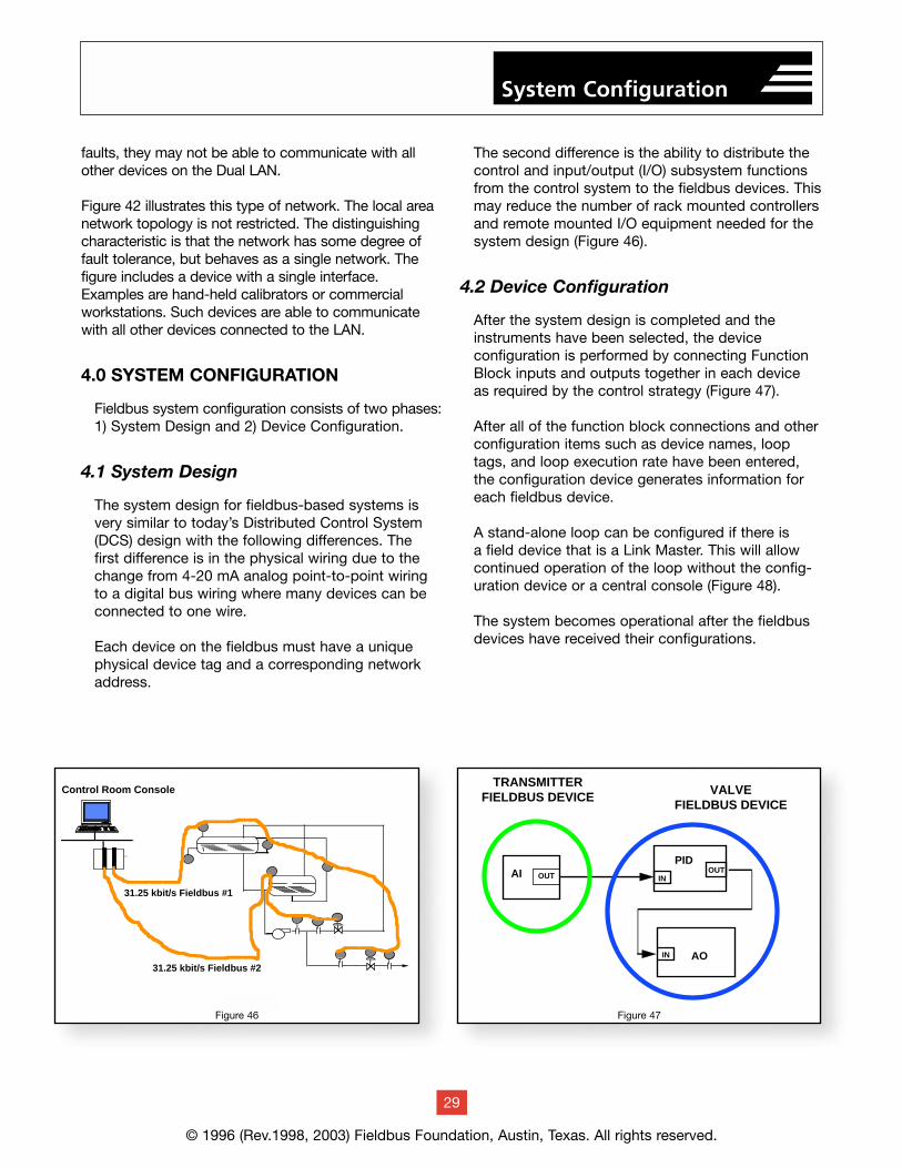
faults, they may not be able to communicate with allother devices on the Dual LAN.
Figure 42 illustrates this type of network. The local areanetwork topology is not restricted. The distinguishingcharacteristic is that the network has some degree offault tolerance, but behaves as a single network. Thefigure includes a device with a single interface.Examples are hand-held calibrators or commercialworkstations. Such devices are able to communicatewith all other devices connected to the LAN.
4.0 SYSTEM CONFIGURATION
Fieldbus system configuration consists of two phases:1) System Design and 2) Device Configuration.
4.1 System Design
The system design for fieldbus-based systems isvery similar to today’s Distributed Control System(DCS) design with the following differences. The first difference is in the physical wiring due to thechange from 4-20 mA analog point-to-point wiringto a digital bus wiring where many devices can beconnected to one wire.
Each device on the fieldbus must have a uniquephysical device tag and a corresponding networkaddress.
The second difference is the ability to distribute thecontrol and input/output (I/O) subsystem functionsfrom the control system to the fieldbus devices. Thismay reduce the number of rack mounted controllersand remote mounted I/O equipment needed for thesystem design (Figure 46).
4.2 Device Configuration
After the system design is completed and theinstruments have been selected, the device configuration is performed by connecting FunctionBlock inputs and outputs together in each device as required by the control strategy (Figure 47).
After all of the function block connections and otherconfiguration items such as device names, looptags, and loop execution rate have been entered,the configuration device generates information foreach fieldbus device.
A stand-alone loop can be configured if there is a field device that is a Link Master. This will allowcontinued operation of the loop without the config-uration device or a central console (Figure 48).
The system becomes operational after the fieldbusdevices have received their configurations.
© 1996 (Rev.1998, 2003) Fieldbus Foundation, Austin, Texas. All rights reserved.
29
System Configuration
Figure 47
Control Room Console
31.25 kbit/s Fieldbus #2
31.25 kbit/s Fieldbus #1
TRANSMITTERFIELDBUS DEVICE
IN
PIDOUTAI
AO
OUT IN
VALVEFIELDBUS DEVICE
Figure 48Figure 46 Figure 47
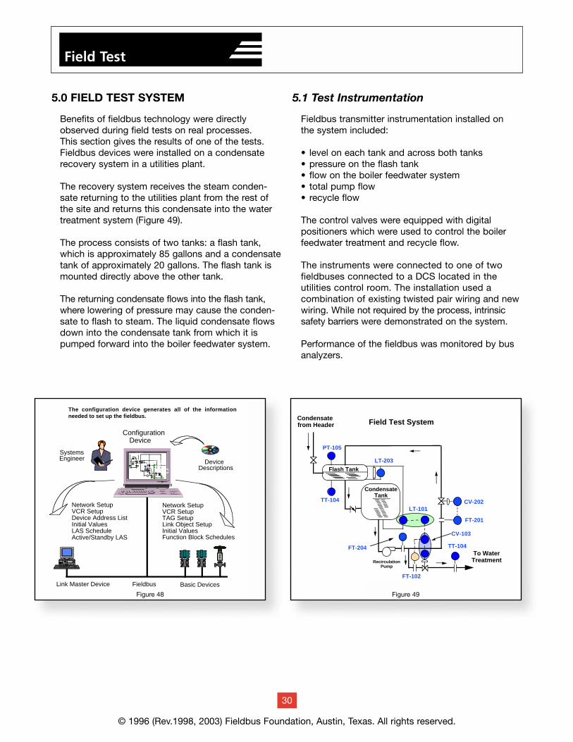
5.0 FIELD TEST SYSTEM
Benefits of fieldbus technology were directlyobserved during field tests on real processes. This section gives the results of one of the tests.Fieldbus devices were installed on a condensaterecovery system in a utilities plant.
The recovery system receives the steam conden-sate returning to the utilities plant from the rest ofthe site and returns this condensate into the watertreatment system (Figure 49).
The process consists of two tanks: a flash tank,which is approximately 85 gallons and a condensatetank of approximately 20 gallons. The flash tank ismounted directly above the other tank.
The returning condensate flows into the flash tank,where lowering of pressure may cause the conden-sate to flash to steam. The liquid condensate flowsdown into the condensate tank from which it ispumped forward into the boiler feedwater system.
5.1 Test Instrumentation
Fieldbus transmitter instrumentation installed on the system included:
• level on each tank and across both tanks• pressure on the flash tank• flow on the boiler feedwater system• total pump flow• recycle flow
The control valves were equipped with digital positioners which were used to control the boilerfeedwater treatment and recycle flow.
The instruments were connected to one of two fieldbuses connected to a DCS located in the utilities control room. The installation used a combination of existing twisted pair wiring and newwiring. While not required by the process, intrinsicsafety barriers were demonstrated on the system.
Performance of the fieldbus was monitored by busanalyzers.
© 1996 (Rev.1998, 2003) Fieldbus Foundation, Austin, Texas. All rights reserved.
30
Field Test
Fieldbus
Configuration Device
Network SetupVCR SetupDevice Address ListInitial Values LAS Schedule Active/Standby LAS
Network SetupVCR SetupTAG SetupLink Object SetupInitial Values Function Block Schedules
Link Master Device
DeviceDescriptions
Basic Devices
PTTTTT
FICFTFTLIC
TIFICLT
FTTT
SystemsEngineer
The configuration device generates all of the information needed to set up the fieldbus.
Figure 49Figure 50
Field Test System
LT
Condensate from Header
Flash Tank
PT-105
CondensateTank
To WaterTreatment
TT-104
LT-203
LT-101
TT-104
FT-102
CV-103
CV-202
FT-201
FT-204
FTRecirculationPump
Figure 48 Figure 49
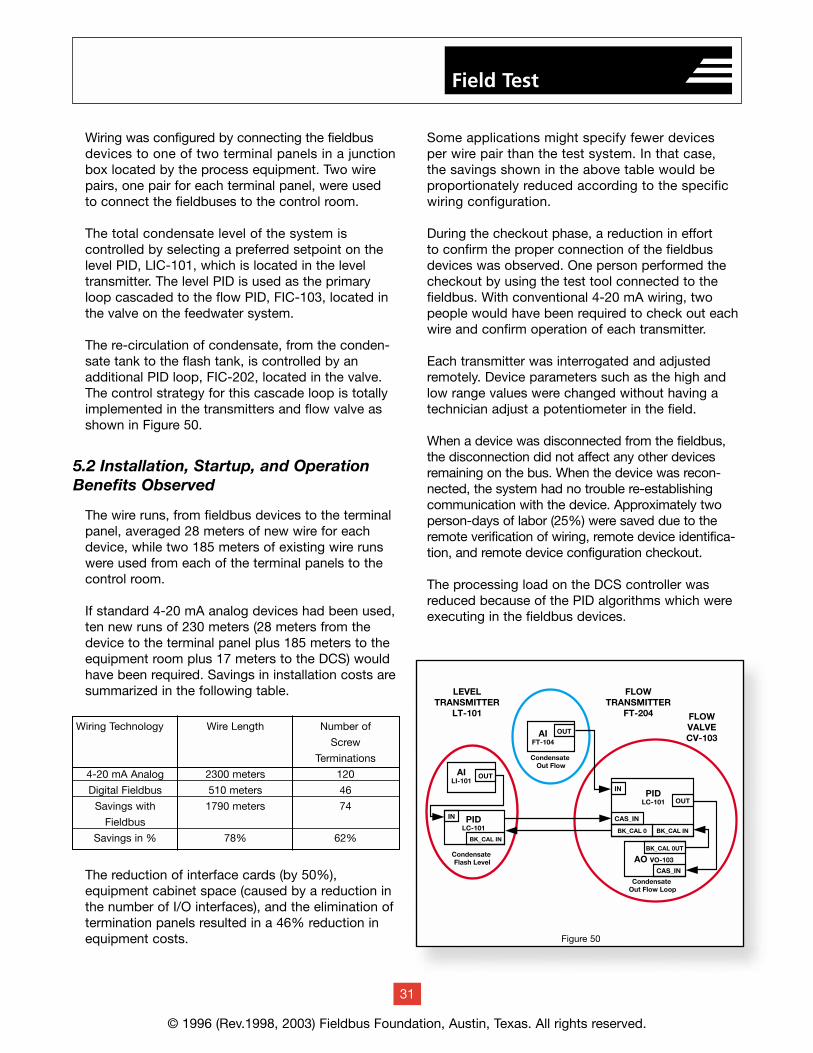
Wiring was configured by connecting the fieldbusdevices to one of two terminal panels in a junctionbox located by the process equipment. Two wirepairs, one pair for each terminal panel, were used to connect the fieldbuses to the control room.
The total condensate level of the system is controlled by selecting a preferred setpoint on thelevel PID, LIC-101, which is located in the leveltransmitter. The level PID is used as the primaryloop cascaded to the flow PID, FIC-103, located inthe valve on the feedwater system.
The re-circulation of condensate, from the conden-sate tank to the flash tank, is controlled by an additional PID loop, FIC-202, located in the valve.The control strategy for this cascade loop is totallyimplemented in the transmitters and flow valve asshown in Figure 50.
5.2 Installation, Startup, and Operation Benefits Observed
The wire runs, from fieldbus devices to the terminalpanel, averaged 28 meters of new wire for eachdevice, while two 185 meters of existing wire runswere used from each of the terminal panels to thecontrol room.
If standard 4-20 mA analog devices had been used,ten new runs of 230 meters (28 meters from thedevice to the terminal panel plus 185 meters to theequipment room plus 17 meters to the DCS) wouldhave been required. Savings in installation costs aresummarized in the following table.
The reduction of interface cards (by 50%), equipment cabinet space (caused by a reduction inthe number of I/O interfaces), and the elimination oftermination panels resulted in a 46% reduction inequipment costs.
Some applications might specify fewer devices per wire pair than the test system. In that case, the savings shown in the above table would beproportionately reduced according to the specificwiring configuration.
During the checkout phase, a reduction in effort to confirm the proper connection of the fieldbusdevices was observed. One person performed thecheckout by using the test tool connected to thefieldbus. With conventional 4-20 mA wiring, twopeople would have been required to check out eachwire and confirm operation of each transmitter.
Each transmitter was interrogated and adjustedremotely. Device parameters such as the high andlow range values were changed without having atechnician adjust a potentiometer in the field.
When a device was disconnected from the fieldbus,the disconnection did not affect any other devicesremaining on the bus. When the device was recon-nected, the system had no trouble re-establishingcommunication with the device. Approximately twoperson-days of labor (25%) were saved due to theremote verification of wiring, remote device identifica-tion, and remote device configuration checkout.
The processing load on the DCS controller wasreduced because of the PID algorithms which wereexecuting in the fieldbus devices.
© 1996 (Rev.1998, 2003) Fieldbus Foundation, Austin, Texas. All rights reserved.
31
Field Test
Wiring Technology Wire Length Number of
Screw
Terminations
4-20 mA Analog 2300 meters 120
Digital Fieldbus 510 meters 46
Savings with 1790 meters 74
Fieldbus
Savings in % 78% 62%
Figure 50
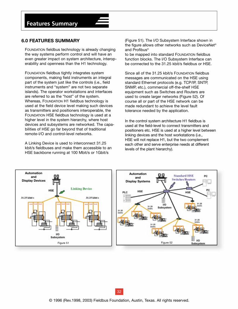
6.0 FEATURES SUMMARY
FOUNDATION fieldbus technology is already changingthe way systems perform control and will have aneven greater impact on system architecture, interop-erability and openness than the H1 technology.
FOUNDATION fieldbus tightly integrates system components, making field instruments an integralpart of the system just like the controls (i.e., fieldinstruments and “system” are not two separateislands). The operator workstations and interfacesare referred to as the “host” of the system.Whereas, FOUNDATION H1 fieldbus technology isused at the field device level making such devicesas transmitters and positioners interoperable, theFOUNDATION HSE fieldbus technology is used at ahigher level in the system hierarchy, where hostdevices and subsystems are networked. The capa-bilities of HSE go far beyond that of traditionalremote-I/O and control-level networks.
A Linking Device is used to interconnect 31.25kbit/s fieldbuses and make them accessible to anHSE backbone running at 100 Mbit/s or 1Gbit/s
(Figure 51). The I/O Subsystem Interface shown inthe figure allows other networks such as DeviceNet®
and Profibus®
to be mapped into standard FOUNDATION fieldbusfunction blocks. The I/O Subsystem Interface canbe connected to the 31.25 kbit/s fieldbus or HSE.
Since all of the 31.25 kbit/s FOUNDATION fieldbusmessages are communicated on the HSE usingstandard Ethernet protocols (e.g. TCP/IP, SNTP,SNMP, etc.), commercial off-the-shelf HSE equipment such as Switches and Routers are used to create larger networks (Figure 52). Ofcourse all or part of the HSE network can be made redundant to achieve the level fault tolerance needed by the application.
In the control system architecture H1 fieldbus is used at the field-level to connect transmitters andpositioners etc. HSE is used at a higher level betweenlinking devices and the host workstations (i.e., HSE will not replace H1, but the two complementeach other and serve enterprise needs at different levels of the plant hierarchy).
© 1996 (Rev.1998, 2003) Fieldbus Foundation, Austin, Texas. All rights reserved.
32
Features Summary
Figure 51 Figure 52
Automationand
Display Devices
Automationand
Display Systems
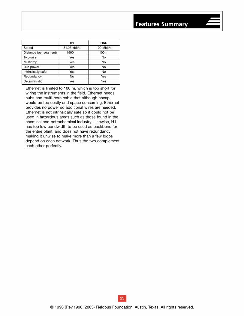
Ethernet is limited to 100 m, which is too short forwiring the instruments in the field. Ethernet needshubs and multi-core cable that although cheap,would be too costly and space consuming. Ethernetprovides no power so additional wires are needed.Ethernet is not intrinsically safe so it could not beused in hazardous areas such as those found in thechemical and petrochemical industry. Likewise, H1has too low bandwidth to be used as backbone forthe entire plant, and does not have redundancymaking it unwise to make more than a few loopsdepend on each network. Thus the two complementeach other perfectly.
© 1996 (Rev.1998, 2003) Fieldbus Foundation, Austin, Texas. All rights reserved.
33
Features Summary
H1 HSE
Speed 31.25 kbit/s 100 Mbit/s
Distance (per segment) 1900 m 100 m
Two-wire Yes No
Multidrop Yes No
Bus power Yes No
Intrinsically safe Yes No
Redundancy No Yes
Deterministic Yes Yes
© 1996 (Rev.1998, 2003) Fieldbus Foundation, Austin, Texas. All rights reserved.
34
Features Summary
Standard Function Blocks Running in Field Devices
Single-loop Integrity – Control in Field – Increased Loop Performance
Reduces Traffic/Load on the Central Control System
More Information for Operators – Including Signal Status
Increases Measurement Accuracy– Reduces A/D Conversions– Supports All Digital Sensor Integration
Fault Tolerant – Supports Multiple Link Masters and Time Masters
Reduces Wiring, Cabinets, Power Supplies, and Equipment Room Size
Increases Uptime Due to Better Remote Diagnostics and Less Equipment
Distributed Control on a COTS 100 Megabit perSecond Backbone
Same Function Blocks and Device DescriptionTechnology on H1
Function Block Synchronization on the Backbone
System Time Synchronization – Master Clock(e.g., GPS) to HSE to H1
New Flexible Function Blocks for Hybrid/Batch/PLC/Remote I/O Applications
Supports High Speed Data Generators/Users(e.g., Analyzers, Controllers)
Uses Standard Internet DHCP – Address LeaseReuse Reduces Startup Time
Short Messages Can Be Packed to ReduceInterrupts on Receiving CPUs
Provides Redundant Network Interface andRedundant Devices.
Modern, All-Digital Network – Intelligent Instrumentation
Power and Signal on a Single, Multi-Drop Wire Pair
Distances up to 1,900 Meters – Can Add Repeaters, Fiber Option
Bus, Star and Tree Wiring Topologies
Automatic Device Assignment – No Need for Switches on the Device
Supports Intrinsic Safety, Multiple Devices on an I.S. Barrier
Remote Configuration & Diagnostics, Easy Evolution Due to Function Blocks.
Annunciation Contains Manufacturer Identification and Model Number
Network Independence – Supports Dual LAN and Ring Topologies
Isolated Subnet, Backbone, Device and Subsystem Integration
Built-in Diagnostics – Annunciation of Changes and Network Statistics
Annunciation Contains Manufacturer Identification and Model Number
Network Independence - Supports Dual LAN and Ring Topologies
Isolated Subnet, Backbone, Device and Subsystem Integration
Built-in Diagnostics – Annunciation of Changes and Network Statistics
H1 and HSE Designed for Maximum Flexibility
H1 HSE
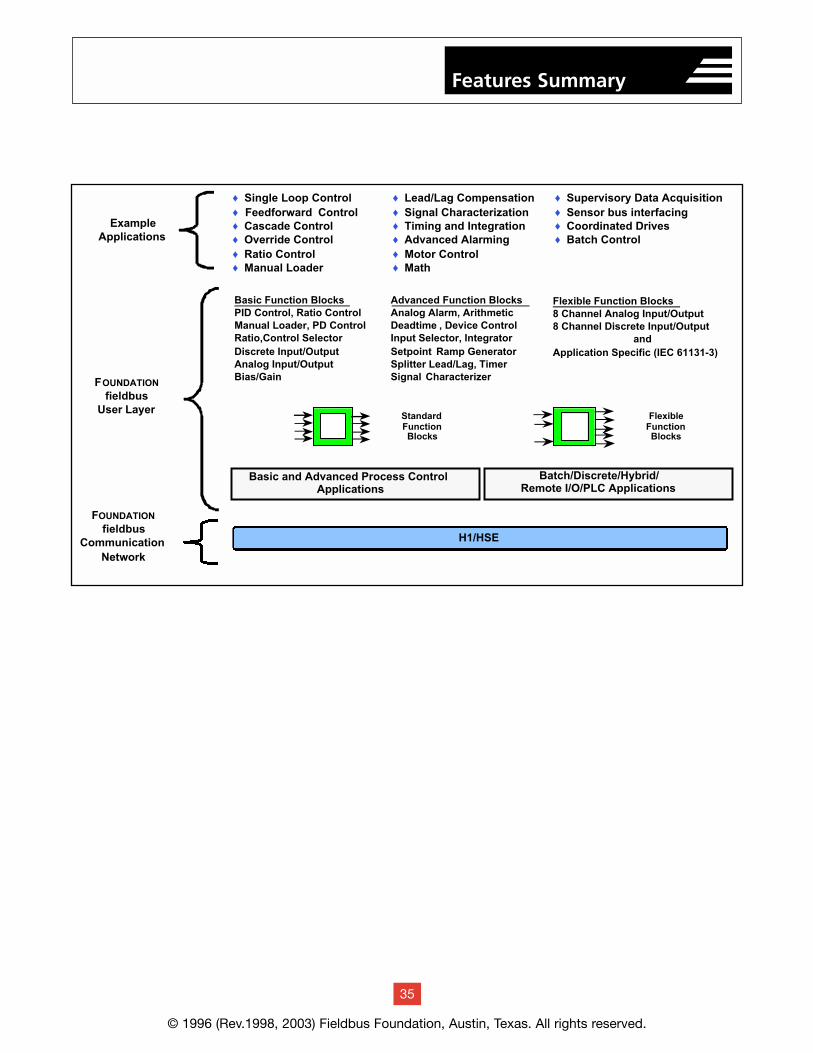
© 1996 (Rev.1998, 2003) Fieldbus Foundation, Austin, Texas. All rights reserved.
35
Features Summary
Flexible Function Blocks8 Channel Analog Input/Output8 Channel Discrete Input/Output
andApplication Specific (IEC 61131-3)
Basic Function BlocksPID Control, Ratio ControlManual Loader, PD ControlRatio,Control SelectorDiscrete Input/OutputAnalog Input/OutputBias/Gain
Advanced Function BlocksAnalog Alarm, ArithmeticDeadtime , Device ControlInput Selector, IntegratorSetpoint Ramp GeneratorSplitter Lead/Lag, TimerSignal Characterizer
Basic and Advanced Process ControlApplications
Batch/Discrete/Hybrid/Remote I/O/PLC Applications
StandardFunctionBlocks
FlexibleFunctionBlocks
♦ Supervisory Data Acquisition♦ Sensor bus interfacing♦ Coordinated Drives♦ Batch Control
♦ Single Loop Control♦ Feedforward Control♦ Cascade Control♦ Override Control♦ Ratio Control♦ Manual Loader
♦ Lead/Lag Compensation♦ Signal Characterization♦ Timing and Integration♦ Advanced Alarming♦ Motor Control♦ Math
H1/HSE
FOUNDATION
fieldbusCommunication
Network
FOUNDATION
fieldbusUser Layer
ExampleApplications
© 1996 (Rev.1998, 2003) Fieldbus Foundation, Austin, Texas. All rights reserved.
23
Field Test
7.0 REFERENCES
1. Fieldbus Standard for Use in Industrial ControlSystems, ISA S50.02.
2. Fieldbus Standard for Use in Industrial ControlSystems, IEC 61158:2000 (ED 2.0).
3. FOUNDATION Fieldbus Specifications, FieldbusFoundation, 1994-1998.
4. Benefits Observed During Field Trials Of AnInteroperable Fieldbus, Kurt A. Zech, FieldbusFoundation, Paper #94-504 — ISA, 1994.
5. Abstract Syntax Notation One (ASN.1). The Tutorialand Reference, Douglas Steedman, TechnologyAppraisals Ltd., 1993, ISBN 1 871802 06 7.
8.0 DOCUMENT LIST
The following documents are part of the FieldbusFoundation products and specifications.
Application Guides (available at www.fieldbus.org)AG-140 31.25 kbit/s Wiring and Installation GuideAG-163 31.25 kbit/s Intrinsically Safe Systems
Application GuideAG-165 Fieldbus Installation and Planning Guide
FF-007: H1, HSE and User Layer TechnicalSpecificationsFF-103 Common File FormatFF-131 Standard TablesFF-593 High Speed Ethernet RedundancyFF-581 System ArchitectureFF-586 Ethernet PresenceFF-588 Field Device Access (FDA) AgentFF-589 HSE System ManagementFF-801 Network Management SpecificationFF-803 HSE Network ManagementFF-806 Data Link Protocol Specification Bridge
Operation AddendumFF-816 31.25 kbit/s Physical Layer Profile
SpecificationFF-821 Data Link Layer Services Subset SpecificationFF-822 Data Link Layer Protocol SpecificationFF-880 System Management SpecificationFF-870 Fieldbus Message SpecificationFF-875 Fieldbus Access Sublayer Specification
FF-890 Function Block Application Process - Part 1FF-891 Function Block Application Process - Part 2FF-892 Function Block Application Process - Part 3FF-893 Function Block Application Process - Part 4FF-894 Function Block Application Process - Part 5FF-900 Device Description Language SpecificationFF-940 31.25 kbit/s Communication ProfileFF-941 HSE Communication Profile
Preliminary Specifications (Available to members only)FF-902 Transducer Block Application Process - Part 1FF-903 Transducer Block Application Process - Part 2
AT-400 Tokenizer KitFD-100 DDL Tokenizer User’s Manual
AT-401 DD Services KitFD-110 DDS User’s Guide
AT-410 Conformance Test KitFD-200 Conformance Tester User’s Guide
AT-420 Interoperability Test KitFD-210 Interoperability Tester User’s Guide
Tech Notes TN-003 Tech Note 3Additional Tech Notes at www.fieldbus.org (members only)
References
36
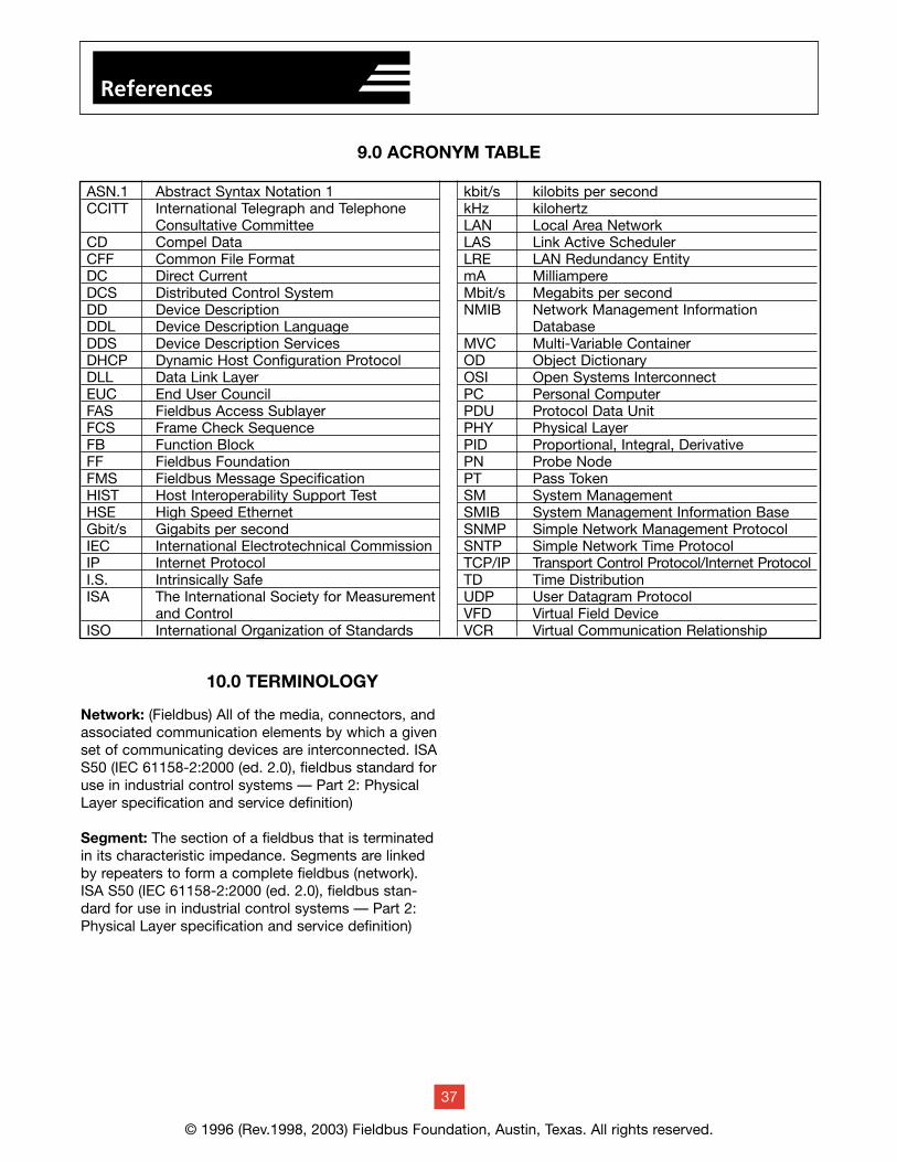
ASN.1 Abstract Syntax Notation 1CCITT International Telegraph and Telephone
Consultative CommitteeCD Compel DataCFF Common File FormatDC Direct CurrentDCS Distributed Control SystemDD Device DescriptionDDL Device Description LanguageDDS Device Description ServicesDHCP Dynamic Host Configuration ProtocolDLL Data Link LayerEUC End User CouncilFAS Fieldbus Access SublayerFCS Frame Check SequenceFB Function BlockFF Fieldbus FoundationFMS Fieldbus Message SpecificationHIST Host Interoperability Support TestHSE High Speed EthernetGbit/s Gigabits per secondIEC International Electrotechnical CommissionIP Internet ProtocolI.S. Intrinsically SafeISA The International Society for Measurement
and ControlISO International Organization of Standards
kbit/s kilobits per secondkHz kilohertzLAN Local Area NetworkLAS Link Active SchedulerLRE LAN Redundancy EntitymA MilliampereMbit/s Megabits per secondNMIB Network Management Information
DatabaseMVC Multi-Variable ContainerOD Object DictionaryOSI Open Systems InterconnectPC Personal ComputerPDU Protocol Data UnitPHY Physical LayerPID Proportional, Integral, DerivativePN Probe NodePT Pass TokenSM System ManagementSMIB System Management Information BaseSNMP Simple Network Management ProtocolSNTP Simple Network Time ProtocolTCP/IP Transport Control Protocol/Internet ProtocolTD Time DistributionUDP User Datagram ProtocolVFD Virtual Field DeviceVCR Virtual Communication Relationship
© 1996 (Rev.1998, 2003) Fieldbus Foundation, Austin, Texas. All rights reserved.
37
9.0 ACRONYM TABLE
10.0 TERMINOLOGY
Network: (Fieldbus) All of the media, connectors, andassociated communication elements by which a givenset of communicating devices are interconnected. ISAS50 (IEC 61158-2:2000 (ed. 2.0), fieldbus standard foruse in industrial control systems — Part 2: PhysicalLayer specification and service definition)
Segment: The section of a fieldbus that is terminatedin its characteristic impedance. Segments are linkedby repeaters to form a complete fieldbus (network).ISA S50 (IEC 61158-2:2000 (ed. 2.0), fieldbus stan-dard for use in industrial control systems — Part 2:Physical Layer specification and service definition)
References