Instruction manual Foundation™ Fieldbus Interface · Instruction manual FOUNDATION Fieldbus™...
32
Instruction manual Foundation™ Fieldbus Interface
Transcript of Instruction manual Foundation™ Fieldbus Interface · Instruction manual FOUNDATION Fieldbus™...

Instruction manualFoundation™ Fieldbus Interface


Instruction manual FOUNDATION Fieldbus™ Interface Page 1
Instruction manual FOUNDATION™ Fieldbus Interface
February 2009
Part no. 4416.254
Rev. 3
Enraf B.V.
P.O. Box 812
2600 AV Delft
Netherlands
Tel. : +31 15 2701 100
Fax : +31 15 2701 111
E-mail : [email protected]
Website : www.honeywellenraf.com
Page 2
Copyright 2005 - 2009 Enraf B.V. All rights reserved.
Reproduction in any form without the prior consent of Enraf B.V. is not allowed. This manual is for information
only. The contents, descriptions and specifications are subject to change without notice. Enraf B.V. accepts no
responsibility for any errors that may appear in this manual.
The warranty terms and conditions applicable in the country of purchase in respect to Enraf B.V. products are
available from your supplier. Please retain them with your proof of purchase.

Preface
Instruction manual FOUNDATION Fieldbus™ Interface Page 3
Preface
This manual is intended for technicians involved with the commissioning and service of the Enraf Series
854 Servo ATG, 970 SmartRadar ATi, 971 SmartRadar LTi and 973 SmartRadar LT with optional FOUNDATION™
Fieldbus Interface.
A description preceding the technical procedures gives the technical information necessary to understand its
functioning. It is recommended to read this description prior to performing any of the procedures.
Safety and prevention of damage
Refer to the chapter Safety in the instruction manual of the 854 Servo ATG, 970 SmartRadar ATi,
971 SmartRadar LTi and 973 SmartRadar LT for detailed safety instructions.
"Warnings", "Cautions", and "Notes" have been used throughout this manual to bring special matters to the
immediate attention of the reader.
• A Warning concerns danger to the safety of the technician or user;
• A Caution draws attention to an action which may damage the equipment;
• A Note points out a statement deserving more emphasis than the general text, but does not deserve a
"Warning" or a "Caution".
The sequence of steps in a procedure may also be important from the point of view of personal safety and
prevention of damage; it is therefore advised not to change the sequence of procedure steps or modify any
procedure in any other way.
Legal aspects
The commissioning and troubleshooting to the instrument may only be conducted by qualified engineers, trained
by Enraf and with knowledge of safety regulations for working in hazardous areas.
The information in this manual is the copyright property of Enraf B.V., Netherlands.
Enraf B.V. disclaims any responsibility for personal injury or damage to equipment caused by:
• Deviation from any of the prescribed procedures;
• Execution of activities that are not prescribed;
• Neglect of the general safety precautions for handling tools and use of electricity.
EC declaration of conformity
This instrument is in conformity with the protection requirements of EC Council Directive 93/68/EEC.
The CE conformity marking fulfills the provisions of:
• 89/336/EEC regarding EMC:
EN 50081-2 Generic Emission Standard
EN 50082-2 Generic Immunity Standard
• 73/23/EEC regarding Low Voltage Directive
• 94/09/EEC regarding ATEX
• 97/23/EEC regarding PED Directive
Additional information
Please do not hesitate to contact Enraf or its representative if you require any additional information.

Table of contents
Page 4
Table of contents
1 Introduction 5 2 FOUNDATION™ Fieldbus Technical Data 6
2.1 Registration 7 2.2 Transmission 7 2.3 Features 7 2.4 Data files 7
3 Wiring and electrical characteristics 8 4 FOUNDATION™ Fieldbus blocks 9
4.1 Resource Block 10 4.2 Channels 12 4.3 Function Blocks 12
4.3.1 Simulate Jumper 12 4.3.2 Write Protection Jumper 12 4.3.3 Engineering Units 12
4.4 Transducer Block: Product Level 13 4.5 Transducer Block: Water Level 14 4.6 Transducer Block: Temperature 15 4.7 Transducer Block: Pressure 16 4.8 Transducer Block: Contact Switch 17
Appendix A Position of Write Lock and Simulation jumper 18 Appendix B FF parameters 19 Appendix C Related documents 28

Introduction
Instruction manual FOUNDATION Fieldbus™ Interface Page 5
1 Introduction
By means of the FOUNDATION™ Fieldbus Interface (FFI) Enraf offers the option to integrate the SmartRadar and
servo level gauge series directly into FOUNDATION™ Fieldbus H1 network topologies. The basis function of the
FFI is to convert all gauging data of Enraf’s level gauge products into FOUNDATION™ Fieldbus.
The FF H1 interface is an intrinsically safe interface and can therefore be used in hazardous as well as in non-
hazardous environments.
The FFI offers by means of five Analog Input (AI) function blocks and one Discrete Output (DO) function block a
wide variety of functionality and process variables on the FF network. These function blocks can be freely used
to present six different measured values and to control an internal contact switch.
The process parameters that can be used as an input for the AI blocks are:
• Product level
• Radar sensor temperature (not available for the servo gauge)
• Product Temperature
• Vapour Temperature
• Vapour Pressure
• Observed Density
• Water Level
.
For reading this manual basic FOUNDATION™ Fieldbus knowledge is expected.

Technical Data
Page 6
2 Abbreviation list
AI : Analog Input
ATEX : ATmosphères EXplosives
AWG : American Wire Gauge
dB/m : Decibel per meter
DO : Digital Output
FFI : Foundation™ Fieldbus Interface
FISCO : Fieldbus Intrinsically Safe Concept
HART : Highway Addressable Remote Transmitter
HIMS : Hybrid Inventory Measurement System
HTG : Hydrostatic Tank Gauging
IEC : International Electrotechnical Commission
IS : Intrinsically Safe
ITK : Interoperability Test Kit
Kbit/sec : Kilobits per second
RB : Resource Block
TB : Transducer Block

Introduction
Instruction manual FOUNDATION Fieldbus™ Interface Page 7
3 FOUNDATION™ Fieldbus Technical Data
3.1 Registration
Manufacturer ID : 'N' 'R' 'F' (0x4E5246).
Device ID:
854 Servo ATG : 800 (0x320)
970 SmartRadar ATi : 900 (0x384)
971 SmartRadar LTi : 900 (0x384)
973 SmartRadar LT : 900 (0x384)
3.2 Transmission
Type : International open fieldbus physical layer standard IEC 1158-2
Physical layer type : 112 standard power signaling, separately powered I.S.
Protocol : FOUNDATION™ Fieldbus H1
Data rate : 31.25 kbit/sec
3.3 Features
H1 device class : Basic device
Number of VCR’s : 24
Jumpers : write lock and simulation
(see Appendix A for the location of the jumpers).
Polarity insensitive : Yes
Stack manufacturer : Softing AG, revision 2.11
Interoperability Test Kit version : ITK 4.6
FF blocks:
1 x Resource Block (RB)
5 x Transducer Block (TB) : Product Level
Water Level
Temperature (Vapour and Product)
Pressure (Vapour Pressure and Observed Density)
Contact Switch
6 x Analog Input (AI)
1 x Discrete Output (DO)
3.4 Data files
Servo : Device Description file: 4E5246\0320\0101.ffo
Capability file: 4E5246\0320\010101.cff
Symbol file 4E5246\0320\0101.sym
SmartRadar : Device Description file: 4E5246\0384\0101.ffo
Capability file: 4E5246\0384\010101.cff
Symbol file 4E5246\0384\0101.sym

Technical Data
Page 8
4 Wiring and electrical characteristics
Cabling (recommended)
Fieldbus Type A (Shielded twisted pair plus overall screen)
Wire size : 18 AWG (0.8 mm)
Attenuation : 3 dB/km at 39 kHz
Characteristic Impedance : 100 Ohms
Shield : 90% coverage
Grounding
To suppress low-frequency equalizing in systems without equipotential bonding, we recommend connecting only
one side of the cable shield directly with local ground (normally connected through the cable gland to the
external housing) and capacitive connection to all other grounding points. The next figure shows a possible
implementation.
junction box
gauge
Control room equipment
PE PE PE
Connection
Please refer to the Instrument Installation guide for the connection instructions.
Maximum distance (without repeaters)
1900 meter (6270 feet)
Power supply
The fieldbus interface is bus powered and is galvanic isolated from the other parts of the gauge. The FFI has the
following characteristics:
Voltage : 9 V – 24 V
Operating current : 11 mA
Maximum current (startup) : 16,70 mA
Polarity
The FFI is polarity insensitive.
I.S. parameters
The Fielbus Interface is conform to the FISCO model of EN-IEC 60079-27:2003 with following parameters
Ui : • 24 V 24 V
Ii : • 380 mA 380 mA
Pi : • 5,32 W 5,32 W
Li : < 6,5 µH
Ci : < 1,8 nF
Approvals : IEC Ex : Ex ia IIC
ATEX : II(2) G [EEx ia] II C
Ta = -40°C … + 85°C

Wiring and electrical characteristics
Instruction manual FOUNDATION Fieldbus™ Interface Page 9
5 FOUNDATION™ Fieldbus blocks The FOUNDATION™ Fieldbus Interface has a total of five Transducer Blocks, six Function Blocks and one
Resource block.
Resource Block
Function Blocks
FOUNDATION™ Fieldbus Interface
Temperature
Pressure
Analog Input
Analog Input
Analog Input
Analog Input
Water Level
Contact Switch Digital Output
Analog Input
Analog Input
Radar Sensor
Temperature
Product Temperature
Vapour Temperature
Vapour Pressure
Observed Density
Water Level
Contact Switch
Transducer Blocks Channels
Resource block
Product LevelProduct Level
1
8
3
4
5
6
2
7

Foundation Fieldbus blocks
Page 10
5.1 Resource Block The Resource Block (RB) contains diagnostic, hardware and electronics information. It shows the details and of
the gauge and the FFI. Some of the attributes are listed below. The names between brackets are the names
used in the device descriptor.
Manufacturer ID (MANUFAC_ID)
Holds the Enraf B.V. manufacturer ID : 'N' 'R' 'F' (0x4E5246).
Device Type (DEV_TYPE) Holds the device type:
854 Servo ATG 800
970 SmartRadar ATi 900
971 SmartRadar LTi 900
973 SmartRadar LT 900
FFI Software Revision (FFI_SW_REVISION)
The Enraf FOUNDATION™ Fieldbus Interface software revision.
FFI Hardware Revision (FFI_HW_REVISION)
The Enraf FOUNDATION™ Fieldbus Interface hardware revision.
Available Gauge options (AVAILABLE_GAUGE_OPTIONS)
The options available in this gauge and are supported by the FOUNDATION™ Fieldbus interface. This
could be as much as six options:
� Product level
� Product Temperature
� Vapour Temperature
� Vapour Pressure
� Observed Density
� Water Level
� Contact Switch
Disable / Enable Alarms and Events (ALM_EVT_OPTION)
With these attributes it is possible to turn off an alarm or event, in such a way that an alarm or event
is not triggered even if the conditions are met. The table below shows the coding of this attribute.
The attribute is bit enumerated. When the bit corresponding with the alarm or event is set the alarm
or event is suppressed.
Attribute code (hex) Attribite code (binary) Alarm / Event
0x0001 ---- ---- ---- 0001 Radar measurement malfunction
0x0002 ---- ---- ---- 0010 General radar signal processing warning
0x0004 ---- ---- ---- 0100 Reduced accuracy detected by level gauge
0x0008 ---- ---- ---- 1000 Water level measurement malfunction
0x0010 ---- ---- 0001 ---- Gas temperature measurement malfunction
0x0020 ---- ---- 0010 ---- Vapour temperature measurement malfunction
0x0040 ---- ---- 0100 ---- Temperature element fail
0x0080 ---- ---- 1000 ---- Transmitter or interface fail
0x0100 ---- 0001 ---- ---- Transmitter exceeding range
0x0200 ---- 0010 ---- ---- Relais failed
0x0400 ---- 0100 ---- ---- Relais not mounted
0x0800 ---- 1000 ---- ---- General fatal error
Each alarm or event has this option individually. It is not recommended to use this option.

Foundation Fieldbus blocks
Instruction manual FOUNDATION Fieldbus™ Interface Page 11
Device Software Version (DEVICE_SOFTWARE_VERSION)
Identification string containing the software version of the main and sensor boards.
Radar Sensor Board Software Version (DAB_VERSION)
Radar sensor board software version.
Operating Hours (OPERATING_HOURS)
Hours running since the instrument is turned on for the first time.
ALARM: General fatal error
If this alarm is set a serious error is encountered. This could be for example a serious hardware
error. Please contact Enraf B.V. for support.
FFI Status (FFI_STATUS)
The Foundation™ Fieldbus Interface status. This attribute is bit enumerated (see table below).
Status code Description
0x01 FFI operates without failure Device works normal. No action required.
0x02 EEPROM failure
0x04 RAM failure
0x08 CRC failure
Memory error. Please contact Enraf B.V.
for support.
0x10 Sensor board not available
0x20 Fatal serial com. error
0x40 Serial communication lost
Internal hardware error. Please contact
Enraf B.V. for support.

Foundation Fieldbus blocks
Page 12
5.2 Channels
The FFI has eight channels that can be used to connect the resource blocks to the function blocks.
channel Description
1 Product Level
2 Water Level
3 Product Temperature
4 Vapour Temperature
5 Vapour Pressure
6 Observed Density
7 Contact Switch
8 Radar Sensor Temperature
Channel 8 (Radar Sensor Temperature) is for diagnostic purposes only.
5.3 Function Blocks The FFI has six Analog Input blocks and one Discrete Output block that can be used to connect the resource
blocks
5.3.1 Simulate Jumper
The simulate jumper is used in conjunction with the Analog Input (AI) function block. This switch is used to
simulate the measurement and as a lock-out feature for the AI function block. To enable the simulate feature,
switch into position “ENABLE” while the transmitter is powered.
Note: When power is cycled to the transmitter, simulation is automatically disabled regardless of the position of
the jumper. This prevents the transmitter from being accidentally left in simulation mode. Therefore, to
enable the simulate feature, the jumper must be inserted after power is applied to the transmitter.
5.3.2 Write Protection Jumper
With the write protection jumper the FFI can be set to read only or to read and write access.
5.3.3 Engineering Units
The Analog Input blocks support different engineering units.
Symbol Unit name
m Meter
ft Feet
in Inch
°C Celsius
°F Fahrenheit
Pa Pascal
kPa Kilopascal
psi Pounds per square inch
kg/m³ kilogram per cubic meter
lbm/ft³ pounds per cubic foot
degAPI degrees API
% Percent

Foundation Fieldbus blocks
Instruction manual FOUNDATION Fieldbus™ Interface Page 13
5.4 Transducer Block: Product Level The Product Level Transducer Block connects an AI block with the level sensor board. Due to the difference in
measuring principle the transducer differs for the SmartRadar series and the servo gauge.
For proper operation some items in the gauge need to be set to the right value.
Item Value Description
GT ‘B’ The gauge communication protocol must be set to GPU protocol.
DE ‘I’ The level type must be set to innage.
If one of these items is not set correct a block error is set.
Primary Value (channel: Product Level)
The primary value of this transducer block is the Product Level. This value can be directed to an
Analog Input block via the channel ‘Product Level’.
Secondary Value (channel: Radar Sensor Temperature) (Not applicable for 854 Servo ATG)
This value is the measured temperature inside the Radar Sensor. This value can be directed to an
AI block via the channel ‘Radar Sensor Temperature’.
Engineering units
Following level units are supported by this block for the primary value:
Symbol Unit name
m Meter
ft Feet
in Inch
These engineering units can (also) be set via the AI block.
Alarms and Events
The supported alarms and events supported are:
Alarm / Event Description
Alarm Radar measurement malfunction
Event General radar signal processing warning
Event Reduced accuracy detected by level gauge
Servo Commands (only applicable for Servo)
This block supports Servo Commands. The supported commands are:
Command Equivalent Item
Servo command unlock UN
Servo command lock test LT
Servo command block BL
Servo command test gauge TG
Servo command verify calib CA

Foundation Fieldbus blocks
Page 14
5.5 Transducer Block: Water Level The Water Level Transducer Block connects an AI block with the water sensor.
For proper operation some items in the gauge need to be set to the right value.
Item Value Description
GT ‘B’ The gauge communication protocol must be set to GPU protocol.
DE ‘I’ The level type must be set to innage.
If one of these items is not set correct a block error is set.
Primary Value (channel: Product Level)
The primary value of this transducer block is the Water Level. This value can be directed to an
Analog Input block via the channel ‘Water Level’.
Secondary Value
This block has no Secondary Value.
Engineering units
Following level units are supported by this block for the primary value:
Symbol Unit name
m Meter
ft Feet
in Inch
These engineering units can (also) be set via the AI block.
Alarms and Events
The alarms and events supported are:
Alarm / Event Description
Alarm Water level measurement malfunction

Foundation Fieldbus blocks
Instruction manual FOUNDATION Fieldbus™ Interface Page 15
5.6 Transducer Block: Temperature
The Temperature Transducer Block connects the AI blocks with the product temperature sensor(s) and vapor
temperature sensor(s).
Note: If a temperature option is not available this block will never leave 'Out of Service'.
For proper operation some items in the gauge need to be set to the right value.
Item Value Description
GT ‘B’ The gauge communication protocol must be set to GPU protocol.
If this item is not set correct a block error is set.
Primary Value (channel: Product Temperature)
The primary value of this transducer block is the Product Temperature. This value can be directed
to an AI block via the channel ‘Product Temperature.
Secondary Value (channel: Vapor Temperature)
The secondary value of this transducer block is the Vapor Temperature. This value can be directed
to an AI block via the channel ‘Vapor Temperature’.
Engineering units
Following temperature units are supported by this block for the primary and secondary value:
Symbol Unit name
°C Celsius
°F Fahrenheit
Alarms and Events
Alarm / Event Description
Alarm Gas temperature measurement malfunction
Alarm Vapor temperature measurement malfunction
Event Temperature element fail

Foundation Fieldbus blocks
Page 16
5.7 Transducer Block: Pressure
The Pressure Transducer Block connects the AI blocks with the Vapour pressure sensor(s) and observed
density sensor(s).
Note: If a pressure (Hart® input) option is not available this block will never leave 'Out of Service'.
For proper operation some items in the gauge need to be set to the right value.
Item Value Description
GT ‘B’ The gauge communication protocol must be set to GPU protocol.
If this item is not set correct a block error is set.
Primary Value (channel: Vapour Pressure)
The primary value of this transducer block is the Vapour Pressure. This value can be directed to an
AI block via the channel ‘Vapour pressure’.
Secondary Value (channel: Observed Density)
The secondary value of this transducer block is the Observed Density. This value can be directed to
an AI block via the channel ‘Observed Density’ (HIMS and HTG; obtained bij Hart transmitters).
Engineering units
Following pressure units are supported by this block for the primary value:
Symbol Unit name
Pa Pascal
kPa Kilopascal
psi Pounds per square inch
Following density units are supported by this block for the secondary value:
Symbol Unit name
kg/m³ kilogram per cubic meter
lbm/ft³ pounds per cubic foot
degAPI degrees API
Alarms and Events
Alarm / Event Description
Alarm Transmitter or interface fail
Event Transmitter exceeding range

Foundation Fieldbus blocks
Instruction manual FOUNDATION Fieldbus™ Interface Page 17
5.8 Transducer Block: Contact Switch The Contact Switch Transducer Block connects the DO block with the internal Relay. The FOUNDATION™
Fieldbus system can use this Relay for control.
Alarms and Events
Alarm / Event Description
Alarm Relays failed
Alarm Relays not mounted

Appendix A
Page 18
Appendix A Position of Write Lock and Simulation jumper
Write AccessWrite protect
SimulateNormal

Appendix B
Instruction manual FOUNDATION Fieldbus™ Interface Page 19
Appendix B FF parameters
Resource Block
Parameter Description
ACK_OPTION Selection of whether alarms associated with the function block will be automatically acknowledged.
ALARM_SUM The current alert status, unacknowledged states, unreported states, and disabled states of the alarms associated with the function block.
ALERT_KEY The identification number of the plant unit. This information may be used in the host for sorting alarms, etc.
ALM_EVT_OPTION Option which the user may select to turn on/off an device specific alarm or event.
AVAILABLE_GAUGE_OPTIONS Used to shows connected gauge options.
BLOCK_ALM The block alarm is used for all configuration, hardware, connection failure or system problems in the block. The cause of the alert is entered in the subcode field. The first alert to become active will set the Active status in the Status attribute. As soon as the Unreported status is cleared by the alert reporting task, another block alert may be reported without clearing the Active status, if the subcode has changed.
BLOCK_ERR This parameter reflects the error status associated with the hardware or software components associated with a block. It is a bit string, so that multiple errors may be shown.
CLR_FSTATE Writing a Clear to this parameter will clear the device faultstate state if the field condition, if any, has cleared.
CONFIRM_TIME The minimum time between retries of alert reports.
CYCLE_SEL Used to select the block execution method for this resource.
CYCLE_TYPE Identifies the block execution methods available for this resource.
DAB_VERSION This item contains the software version of the DAB software.
DD_RESOURCE String identifying the tag of the resource which contains the Device Description for this resource.
DD_REV Revision of the DD associated with the resource - used by an interface device to locate the DD file for the resource.
DEV_REV Manufacturer revision number associated with the resource - used by an interface device to locate the DD file for the resource.
DEV_TYPE Manufacturer's model number associated with the resource - used by interface devices to locate the DD file for the resource.
DEVICE_SOFTWARE_VERSION String representing the software versions of the main and option boards of the instrument.
FACTORY_DATA_B Product information.
FACTORY_DATA_C Product information.
FACTORY_DATA_D Product information.
FATAL_TRANSMISSION_BOARD_ERRORS The number of encountered fatal errors on the instrument communication board.
FAULT_STATE Condition set by loss of communcation to an output block, failure promoted to an output block or a physical contact. When faultstate condition is set, then output function blocks will perform their FSTATE actions.
FEATURE_SEL Used to select resource block options.
FEATURES Used to shows supported resource block options.
FFI_HW_REVISION String representing the hardware version of the FFI board of the instrument.
FFI_STATUS The current status of the FFI
FFI_SW_REVISION String representing the software version of the FFI board of the instrument.
FREE_SPACE Percent of memory available for further configuration. Zero in a preconfigured device.
FREE_TIME Percent of the block processing time that is free to process additional blocks.
GPU_ANSWER Enraf service answer channel.
GPU_POLL Enraf service poll parameter.
GPU_REQUEST Enraf service request channel.
GRANT_DENY Options for controlling access of host computers and local control panels to operating, tuning, and alarm parameters of the block.
HARD_TYPES The types of hardware available as channel numbers.
ITK_VER Major revision number of the interoperability test case used to register this device.
LAST_TRANSMISSION_BOARD_ERROR Code representing the last encountered error on the instrument communication board.
LIM_NOTIFY Maximum number of unconfirmed alert notify messages allowed.
MANUFAC_ID Manufacturer identification number - used by an interface device to locate the DD file for the resource.
MAX_NOTIFY Maximum number of unconfirmed alert notify messages possible.
MEMORY_SIZE Available configuration memory in the empty resource. To be checked before attempting a download.

Appendix B
Page 20
MIN_CYCLE_T Time duration of the shortest cycle interval of which the resource is capable.
MODE_BLK The actual, target, permitted, and normal modes of the block.
NV_CYCLE_T Minimum time interval specified by the manufacturer for writing copies of NV parameters to non-volatile memory. NV memory is updated only if there has been a significant change in the dynamic value. The last value saved in NV memory will be available after restart. Zero means that NV data will only be copied to NV memory when an external write request is received.
OPERATING_HOURS The number of operating hours of the instrument.
PHYSICAL_JUMPER_POSITIONS Position of the 6 instrument communication board jumpers (0 = open; 1 = closed).
PRODUCT_ID_CODE Product identification code.
RB_ALARM The resource alarm is used for predefined device specific alarms.
REASON_OF_LAST_INITIALISATION Code representing the reason why the instrument is restarted the last time.
RESTART Allows a manual restart to be initiated. Several degrees of restart are possible. They are 1: Run, 2: Restart resource, 3: Restart with defaults, and 4: Restart processor.
RS_STATE State of the function block application state machine.
SET_FSTATE Allows the faultstate condition to be manually initiated by selecting Set.
SHED_RCAS Time duration at which to give up on computer writes to function block RCas locations.
SHED_ROUT Time duration at which to give up on computer writes to function block ROut locations.
ST_REV The revision level of the static data associated with the function block. The revision value will be incremented each time a static parameter value in the block is changed.
STRATEGY The strategy field can be used to identify grouping of blocks. This data is not checked or processed by the block.
TAG_DESC The user description of the intended application of the block.
TEST_RW Read/write test parameter - used only for conformance testing.
UPDATE_EVT This alert is generated by any change to the static data.
WRITE_ALM This alert is generated if the write lock parameter is cleared.
WRITE_LOCK Shows the state of the hardware switch. If set, no writes from anywhere are allowed. Block inputs will continue to be updated.
WRITE_PRI Priority of the alarm generated by clearing the write lock.
Appendix B
Instruction manual FOUNDATION Fieldbus™ Interface Page 21
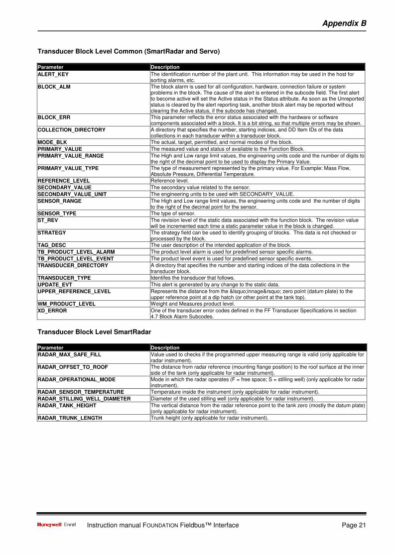
Transducer Block Level Common (SmartRadar and Servo)
Parameter Description
ALERT_KEY The identification number of the plant unit. This information may be used in the host for sorting alarms, etc.
BLOCK_ALM The block alarm is used for all configuration, hardware, connection failure or system problems in the block. The cause of the alert is entered in the subcode field. The first alert to become active will set the Active status in the Status attribute. As soon as the Unreported status is cleared by the alert reporting task, another block alert may be reported without clearing the Active status, if the subcode has changed.
BLOCK_ERR This parameter reflects the error status associated with the hardware or software components associated with a block. It is a bit string, so that multiple errors may be shown.
COLLECTION_DIRECTORY A directory that specifies the number, starting indicies, and DD Item IDs of the data collections in each transducer within a transducer block.
MODE_BLK The actual, target, permitted, and normal modes of the block.
PRIMARY_VALUE The measured value and status of available to the Function Block.
PRIMARY_VALUE_RANGE The High and Low range limit values, the engineering units code and the number of digits to the right of the decimal point to be used to display the Primary Value.
PRIMARY_VALUE_TYPE The type of measurement represented by the primary value. For Example: Mass Flow, Absolute Pressure, Differential Temperature.
REFERENCE_LEVEL Reference level.
SECONDARY_VALUE The secondary value related to the sensor.
SECONDARY_VALUE_UNIT The engineering units to be used with SECONDARY_VALUE.
SENSOR_RANGE The High and Low range limit values, the engineering units code and the number of digits to the right of the decimal point for the sensor.
SENSOR_TYPE The type of sensor.
ST_REV The revision level of the static data associated with the function block. The revision value will be incremented each time a static parameter value in the block is changed.
STRATEGY The strategy field can be used to identify grouping of blocks. This data is not checked or processed by the block.
TAG_DESC The user description of the intended application of the block.
TB_PRODUCT_LEVEL_ALARM The product level alarm is used for predefined sensor specific alarms.
TB_PRODUCT_LEVEL_EVENT The product level event is used for predefined sensor specific events.
TRANSDUCER_DIRECTORY A directory that specifies the number and starting indices of the data collections in the transducer block.
TRANSDUCER_TYPE Identifes the transducer that follows.
UPDATE_EVT This alert is generated by any change to the static data.
UPPER_REFERENCE_LEVEL Represents the distance from the ‘innage’ zero point (datum plate) to the upper reference point at a dip hatch (or other point at the tank top).
WM_PRODUCT_LEVEL Weight and Measures product level.
XD_ERROR One of the transducer error codes defined in the FF Transducer Specifications in section 4.7 Block Alarm Subcodes.
Transducer Block Level SmartRadar
Parameter Description
RADAR_MAX_SAFE_FILL Value used to checks if the programmed upper measuring range is valid (only applicable for radar instrument).
RADAR_OFFSET_TO_ROOF The distance from radar reference (mounting flange position) to the roof surface at the inner side of the tank (only applicable for radar instrument).
RADAR_OPERATIONAL_MODE Mode in which the radar operates (F = free space; S = stilling well) (only applicable for radar instrument).
RADAR_SENSOR_TEMPERATURE Temperature inside the instrument (only applicable for radar instrument).
RADAR_STILLING_WELL_DIAMETER Diameter of the used stilling well (only applicable for radar instrument).
RADAR_TANK_HEIGHT The vertical distance from the radar reference point to the tank zero (mostly the datum plate) (only applicable for radar instrument).
RADAR_TRUNK_LENGTH Trunk height (only applicable for radar instrument).

Appendix B
Page 22
Transducer Block Level Servo
Parameter Description
SERVO_AVERAGE_MEASURED_WEIGHT The avarage force that was found during the balance test (only applicable for servo instrument).
SERVO_COMMAND_BLOCK Servo block command (1 = on; 0 = off) (only applicable for servo instrument).
SERVO_COMMAND_LOCK_TEST Servo lock command (1 = on; 0 = off) (only applicable for servo instrument).
SERVO_COMMAND_TEST_GAUGE Servo test instrument command (1 = on; 0 = off) (only applicable for servo instrument).
SERVO_COMMAND_UNLOCK Servo unlock command (1 = on; 0 = off) (only applicable for servo instrument).
SERVO_COMMAND_VERIFY_CALIB Servo verify calibration command (1 = on; 0 = off) (only applicable for servo instrument).
SERVO_DISPLACER_AREA Displacer area (only applicable for servo instrument).
SERVO_DISPLACER_VOLUME Displacer volume (only applicable for servo instrument).
SERVO_DISPLACER_WEIGHT Displacer weight (only applicable for servo instrument).
SERVO_LIMIT_SWITCH_HIGH_LEVEL The highest allowed position for the displacer during normal operation (only applicable for servo instrument).
SERVO_LIMIT_SWITCH_LOW_LEVEL The lowest allowed position for the displacer during normal operation (only applicable for servo instrument).
SERVO_MAX_UNBALANCED_WEIGHT The maximum force that was found during the balance test (only applicable for servo instrument).
SERVO_MEASURED_DISPLACER_WEIGHT Measured displacer weight (only applicable for servo instrument).
SERVO_MIN_UNBALANCED_WEIGHT The minimum force that was found during the balance test (only applicable for servo instrument).
SERVO_STRESS_TRANSDUCER_FREQ The measured frequency of the stress transducer (only applicable for servo instrument).
SERVO_TANK_TOP_LEVEL Tank top level (only applicable for servo instrument).
Transducer Block Water Level
Parameter Description
ALERT_KEY The identification number of the plant unit. This information may be used in the host for sorting alarms, etc.
BLOCK_ALM The block alarm is used for all configuration, hardware, connection failure or system problems in the block. The cause of the alert is entered in the subcode field. The first alert to become active will set the Active status in the Status attribute. As soon as the Unreported status is cleared by the alert reporting task, another block alert may be reported without clearing the Active status, if the subcode has changed.
BLOCK_ERR This parameter reflects the error status associated with the hardware or software components associated with a block. It is a bit string, so that multiple errors may be shown.
BOTTOM_POSITION_WATER_PROBE Bottom position of the water probe.
COLLECTION_DIRECTORY A directory that specifies the number, starting indicies, and DD Item IDs of the data collections in each transducer within a transducer block.
MODE_BLK The actual, target, permitted, and normal modes of the block.
PRIMARY_VALUE The measured value and status of available to the Function Block.
PRIMARY_VALUE_RANGE The High and Low range limit values, the engineering units code and the number of digits to the right of the decimal point to be used to display the Primary Value.
PRIMARY_VALUE_TYPE The type of measurement represented by the primary value. For Example: Mass Flow, Absolute Pressure, Differential Temperature.
SECONDARY_VALUE The secondary value related to the sensor.
SECONDARY_VALUE_UNIT The engineering units to be used with SECONDARY_VALUE.
SENSOR_RANGE The High and Low range limit values, the engineering units code and the number of digits to the right of the decimal point for the sensor.
SENSOR_TYPE The type of sensor.
ST_REV The revision level of the static data associated with the function block. The revision value will be incremented each time a static parameter value in the block is changed.
STRATEGY The strategy field can be used to identify grouping of blocks. This data is not checked or processed by the block.
TAG_DESC The user description of the intended application of the block.
TB_WATER_LEVEL_ALARM The water level alarm is used for predefined sensor specific alarms.
TRANSDUCER_DIRECTORY A directory that specifies the number and starting indices of the data collections in the transducer block.
TRANSDUCER_TYPE Identifes the transducer that follows.
UPDATE_EVT This alert is generated by any change to the static data.
XD_ERROR One of the transducer error codes defined in the FF Transducer Specifications in section 4.7 Block Alarm Subcodes.

Appendix B
Instruction manual FOUNDATION Fieldbus™ Interface Page 23
Transducer Block Temperature
Parameter Description
ALERT_KEY The identification number of the plant unit. This information may be used in the host for sorting alarms, etc.
BLOCK_ALM The block alarm is used for all configuration, hardware, connection failure or system problems in the block. The cause of the alert is entered in the subcode field. The first alert to become active will set the Active status in the Status attribute. As soon as the Unreported status is cleared by the alert reporting task, another block alert may be reported without clearing the Active status, if the subcode has changed.
BLOCK_ERR This parameter reflects the error status associated with the hardware or software components associated with a block. It is a bit string, so that multiple errors may be shown.
COLLECTION_DIRECTORY A directory that specifies the number, starting indicies, and DD Item IDs of the data collections in each transducer within a transducer block.
MODE_BLK The actual, target, permitted, and normal modes of the block.
MULTI_TEMP_ELEMENT_POSITION_0 Position of temperature element 0.
MULTI_TEMP_ELEMENT_POSITION_1 Position of temperature element 1.
MULTI_TEMP_ELEMENT_POSITION_2 Position of temperature element 2.
MULTI_TEMP_ELEMENT_POSITION_3 Position of temperature element 3.
MULTI_TEMP_ELEMENT_POSITION_4 Position of temperature element 4.
MULTI_TEMP_ELEMENT_POSITION_5 Position of temperature element 5.
MULTI_TEMP_ELEMENT_POSITION_6 Position of temperature element 6.
MULTI_TEMP_ELEMENT_POSITION_7 Position of temperature element 7.
MULTI_TEMP_ELEMENT_POSITION_8 Position of temperature element 8.
MULTI_TEMP_ELEMENT_POSITION_9 Position of temperature element 9.
MULTI_TEMP_ELEMENT_POSITION_10 Position of temperature element 10.
MULTI_TEMP_ELEMENT_POSITION_11 Position of temperature element 11.
MULTI_TEMP_ELEMENT_POSITION_12 Position of temperature element 12.
MULTI_TEMP_ELEMENT_POSITION_13 Position of temperature element 13.
MULTI_TEMP_ELEMENT_POSITION_14 Position of temperature element 14.
MULTI_TEMP_ELEMENT_POSITION_15 Position of temperature element 15.
MULTI_TEMP_PRODUCT_IMMER_DEPTH Part of the probe below product.
MULTI_TEMP_VAPOUR_IMMER_DEPTH Part of the probe above product.
MULTI_TEMPERATURE_LEVEL_OFFSET The position of the anchoring-eye in respect with the zero-level of the tank.
MULTI_TEMPERATURE_SENSOR_LENGTH Length of the used MTT probe.
NUMBER_OF_MULTI_TEMP_ELEMENTS The number of multi temperature elements in the probe.
PRIMARY_VALUE The measured value and status of available to the Function Block.
PRIMARY_VALUE_RANGE The High and Low range limit values, the engineering units code and the number of digits to the right of the decimal point to be used to display the Primary Value.
PRIMARY_VALUE_TYPE The type of measurement represented by the primary value. For Example: Mass Flow, Absolute Pressure, Differential Temperature.
RTD_OFFSET Offset for the RTD measurement. This value is subtracted from the calculated spot-temperatures.
RTD_POSITION The position of the RTD element.
SECONDARY_VALUE The secondary value related to the sensor.
SECONDARY_VALUE_UNIT The engineering units to be used with SECONDARY_VALUE.
SENSOR_RANGE The High and Low range limit values, the engineering units code and the number of digits to the right of the decimal point for the sensor.
SENSOR_TYPE The type of sensor.
ST_REV The revision level of the static data associated with the function block. The revision value will be incremented each time a static parameter value in the block is changed.
STRATEGY The strategy field can be used to identify grouping of blocks. This data is not checked or processed by the block.
TAG_DESC The user description of the intended application of the block.
TB_TEMPERATURE_ALARM The temperature alarm is used for predefined sensor specific alarms.
TB_TEMPERATURE_EVENT The temperature event is used for predefined sensor specific events.
TEMPERATURE_SWITCH_HYSTERESIS Hysteris value that is used to determine if an element is used for product temperature or vapour temperature calculation.
TRANSDUCER_DIRECTORY A directory that specifies the number and starting indices of the data collections in the transducer block.
TRANSDUCER_TYPE Identifes the transducer that follows.
UPDATE_EVT This alert is generated by any change to the static data.
WM_PRODUCT_TEMPERATURE Weight and Measures product temperature.
XD_ERROR One of the transducer error codes defined in the FF Transducer Specifications in section 4.7 Block Alarm Subcodes.

Appendix B
Page 24
Transducer Block Pressure
Parameter Description
ALERT_KEY The identification number of the plant unit. This information may be used in the host for sorting alarms, etc.
AVAILABLE_PRESSURE_TRANSMITTERS Available pressure transmitters. (- = not available; 1/2/3 = available).
BLOCK_ALM The block alarm is used for all configuration, hardware, connection failure or system problems in the block. The cause of the alert is entered in the subcode field. The first alert to become active will set the Active status in the Status attribute. As soon as the Unreported status is cleared by the alert reporting task, another block alert may be reported without clearing the Active status, if the subcode has changed.
BLOCK_ERR This parameter reflects the error status associated with the hardware or software components associated with a block. It is a bit string, so that multiple errors may be shown.
COLLECTION_DIRECTORY A directory that specifies the number, starting indicies, and DD Item IDs of the data collections in each transducer within a transducer block.
MODE_BLK The actual, target, permitted, and normal modes of the block.
PRIMARY_VALUE The measured value and status of available to the Function Block.
PRIMARY_VALUE_RANGE The High and Low range limit values, the engineering units code and the number of digits to the right of the decimal point to be used to display the Primary Value.
PRIMARY_VALUE_TYPE The type of measurement represented by the primary value. For Example: Mass Flow, Absolute Pressure, Differential Temperature.
SECONDARY_VALUE The secondary value related to the sensor.
SECONDARY_VALUE_UNIT The engineering units to be used with SECONDARY_VALUE.
SENSOR_P1_MAXIMUM_TRIP_PRESSURE Maximum trip pressure of P1.
SENSOR_P1_MINIMUM_TRIP_PRESSURE Minimum trip pressure of P1.
SENSOR_P1_OFFSET The pressure offset value with which the measured pressure in P1 is compensated before further calculations.
SENSOR_P1_TEMPERATURE Value of the temperature sensor in P1.
SENSOR_P2_MAXIMUM_TRIP_PRESSURE Maximum trip pressure of P2.
SENSOR_P2_MINIMUM_TRIP_PRESSURE Minimum trip pressure of P2.
SENSOR_P2_OFFSET The pressure offset value with which the measured pressure in P2 is compensated before further calculations.
SENSOR_P2_TEMPERATURE Value of the temperature sensor in P2.
SENSOR_P3_MAXIMUM_TRIP_PRESSURE Maximum trip pressure of P3.
SENSOR_P3_MINIMUM_TRIP_PRESSURE Minimum trip pressure of P3.
SENSOR_P3_OFFSET The pressure offset value with which the measured pressure in P3 is compensated before further calculations.
SENSOR_P3_TEMPERATURE Value of the temperature sensor in P3.
SENSOR_RANGE The High and Low range limit values, the engineering units code and the number of digits to the right of the decimal point for the sensor.
SENSOR_TYPE The type of sensor.
ST_REV The revision level of the static data associated with the function block. The revision value will be incremented each time a static parameter value in the block is changed.
STRATEGY The strategy field can be used to identify grouping of blocks. This data is not checked or processed by the block.
TAG_DESC The user description of the intended application of the block.
TB_PRESSURE_ALARM The pressure alarm is used for predefined sensor specific alarms.
TB_PRESSURE_EVENT The pressure event is used for predefined sensor specific events.
TRANSDUCER_DIRECTORY A directory that specifies the number and starting indices of the data collections in the transducer block.
TRANSDUCER_TYPE Identifes the transducer that follows.
UPDATE_EVT This alert is generated by any change to the static data.
XD_ERROR One of the transducer error codes defined in the FF Transducer Specifications in section 4.7 Block Alarm Subcodes.

Appendix B
Instruction manual FOUNDATION Fieldbus™ Interface Page 25
Transducer Block Contact Switch
Parameter Description
ALERT_KEY The identification number of the plant unit. This information may be used in the host for sorting alarms, etc.
BLOCK_ALM The block alarm is used for all configuration, hardware, connection failure or system problems in the block. The cause of the alert is entered in the subcode field. The first alert to become active will set the Active status in the Status attribute. As soon as the Unreported status is cleared by the alert reporting task, another block alert may be reported without clearing the Active status, if the subcode has changed.
BLOCK_ERR This parameter reflects the error status associated with the hardware or software components associated with a block. It is a bit string, so that multiple errors may be shown.
COLLECTION_DIRECTORY A directory that specifies the number, starting indicies, and DD Item IDs of the data collections in each transducer within a transducer block.
CONTACT_SWITCH_STATUS Current status of the contact switch.
FINAL_VALUE_D The requested valve position and status written by a discrete Function Block.
MODE_BLK The actual, target, permitted, and normal modes of the block.
RADAR_CONTACT_SWITCH_MODE Active mode of the contact switch.
SERVO_CONTACT_SWITCH_MODE Active mode of the contact switch.
ST_REV The revision level of the static data associated with the function block. The revision value will be incremented each time a static parameter value in the block is changed.
STRATEGY The strategy field can be used to identify grouping of blocks. This data is not checked or processed by the block.
TAG_DESC The user description of the intended application of the block.
TB_CONTACT_SWITCH_ALARM The contact switch alarm is used for predefined sensor specific alarms.
TRANSDUCER_DIRECTORY A directory that specifies the number and starting indices of the data collections in the transducer block.
TRANSDUCER_TYPE Identifes the transducer that follows.
UPDATE_EVT This alert is generated by any change to the static data.
XD_ERROR One of the transducer error codes defined in the FF Transducer Specifications in section 4.7 Block Alarm Subcodes.

Appendix B
Page 26
Analog Input Block (all) Parameter Description
ACK_OPTION Selection of whether alarms associated with the function block will be automatically acknowledged.
ALARM_HYS Amount the PV must return within the alarm limits before the alarm condition clears. Alarm hysteresis expressed as a percent of the span of the PV.
ALARM_SUM The current alert status, unacknowledged states, unreported states, and disabled states of the alarms associated with the function block.
ALERT_KEY The identification number of the plant unit. This information may be used in the host for sorting alarms, etc.
BLOCK_ALM The block alarm is used for all configuration, hardware, connection failure or system problems in the block. The cause of the alert is entered in the subcode field. The first alert to become active will set the Active status in the Status attribute. As soon as the Unreported status is cleared by the alert reporting task, another block alert may be reported without clearing the Active status, if the subcode has changed.
BLOCK_ERR This parameter reflects the error status associated with the hardware or software components associated with a block. It is a bit string, so that multiple errors may be shown.
CHANNEL The number of the logical hardware channel that is connected to this I/O block. This information defines the transducer to be used going to or from the physical world.
FIELD_VAL Raw value of the field device in % of PV range, with a status reflecting the Transducer condition, before signal characterization (L_TYPE) or filtering (PV_FTIME).
GRANT_DENY Options for controlling access of host computers and local control panels to operating, tuning, and alarm parameters of the block.
HI_ALM The status for high alarm and its associated time stamp.
HI_HI_ALM The status for high high alarm and its associated time stamp.
HI_HI_LIM The setting for high high alarm in engineering units.
HI_HI_PRI Priority of the high high alarm.
HI_LIM The setting for high alarm in engineering units.
HI_PRI Priority of the high alarm.
IO_OPTS Option which the user may select to alter input and output block processing.
L_TYPE Determines if the values passed by the transducer block to the AI block may be used directly (Direct) or if the value is in different units and must be converted linearly (Indirect), or with square root (Ind Sqr Root), using the input range defined for the transducer and the associated output range.
LO_ALM The status of the low alarm and its associated time stamp.
LO_LIM The setting for the low alarm in engineering units.
LO_LO_ALM The status of the low low alarm and its associated time stamp.
LO_LO_LIM The setting of the low low alarm in engineering units.
LO_LO_PRI Priority of the low low alarm.
LO_PRI Priority of the low alarm.
LOW_CUT Limit used in square root processing. A value of zero percent of scale is used in block processing if the transducer value falls below this limit, in % of scale. This feature may be used to eliminate noise near zero from a flow sensor.
MODE_BLK The actual, target, permitted, and normal modes of the block.
OUT The primary analog value calculated as a result of executing the function block.
OUT_SCALE The high and low scale values, engineering units code, and number of digits to the right of the decimal point to be used in displaying the OUT parameter and parameters which have the same scaling as OUT.
PV Either the primary analog value for use in executing the function, or a process value associated with it. May also be calculated from the READBACK value of an AO block.
PV_FTIME Time constant of a single exponential filter for the PV, in seconds.
SIMULATE Allows the transducer analog input or output to the block to be manually supplied when simulate is enabled. When simulate is disabled, the simulate value and status track the actual value and status.
ST_REV The revision level of the static data associated with the function block. The revision value will be incremented each time a static parameter value in the block is changed.
STATUS_OPTS Options which the user may select in the block processing of status.
STRATEGY The strategy field can be used to identify grouping of blocks. This data is not checked or processed by the block.
TAG_DESC The user description of the intended application of the block.
UPDATE_EVT This alert is generated by any change to the static data.
XD_SCALE The high and low scale values, engineering units code, and number of digits to the right of the decimal point used with the value obtained from the transducer for a specified channel.

Appendix B
Instruction manual FOUNDATION Fieldbus™ Interface Page 27
Digital Output Block
Parameter Description
ALERT_KEY The identification number of the plant unit. This information may be used in the host for sorting alarms, etc.
BKCAL_OUT_D The output value and status provided to an upstream block output tracking when the loop is broken, as determined by the status bits. This information is used to provide bumpless transfer to closed loop control.
BLOCK_ALM The block alarm is used for all configuration, hardware, connection failure or system problems in the block. The cause of the alert is entered in the subcode field. The first alert to become active will set the Active status in the Status attribute. As soon as the Unreported status is cleared by the alert reporting task, another block alert may be reported without clearing the Active status, if the subcode has changed.
BLOCK_ERR This parameter reflects the error status associated with the hardware or software components associated with a block. It is a bit string, so that multiple errors may be shown.
CAS_IN_D This parameter is the remote setpoint value, which must come from another Fieldbus block, or a DCS block through a defined link.
CHANNEL The number of the logical hardware channel that is connected to this I/O block. This information defines the transducer to be used going to or from the physical world.
FSTATE_TIME The time in seconds from detection of failure of the output block remote setpoint to the output action of the block output if the condition still exists.
FSTATE_VAL_D The preset discrete SP_D value to use when failure occurs. This value will be used if the I/O option Faultstate to value is selected.
GRANT_DENY Options for controlling access of host computers and local control panels to operating, tuning, and alarm parameters of the block.
IO_OPTS Option which the user may select to alter input and output block processing.
MODE_BLK The actual, target, permitted, and normal modes of the block.
OUT_D The primary discrete value calculated as a result of executing the function block.
PV_D Either the primary discrete value for use in executing the function, or a process value associated with it. May also be calculated from the READBACK value of an DO block.
PV_STATE Index to the text describing the states of a discrete PV.
RCAS_IN_D Target setpoint and status provided by a supervisory Host to a discrete control or output block.
RCAS_OUT_D Block setpoint and status provided to a supervisory Host for back calculation and to allow action to be taken under limiting conditions or mode change.
READBACK_D This indicates the readback of the actual discrete valve or other actuator position, in the transducer state.
SHED_OPT Defines action to be taken on remote control device timeout.
SIMULATE_DISCRETE Allows the transducer analog input or output to the block to be manually supplied when simulate is enabled. When simulate is disabled, the simulate value and status track the actual value and status.
SP_D The discrete setpoint of this block.
ST_REV The revision level of the static data associated with the function block. The revision value will be incremented each time a static parameter value in the block is changed.
STATUS_OPTS Options which the user may select in the block processing of status.
STRATEGY The strategy field can be used to identify grouping of blocks. This data is not checked or processed by the block.
TAG_DESC The user description of the intended application of the block.
UPDATE_EVT This alert is generated by any change to the static data.
XD_STATE Index to the text describing the states of a discrete for the value obtained from the transducer.

Appendix C
Page 28
Appendix C Related documents
Description Part No.
Instruction manual 854 Servo Gauge 4416220
Instruction manual 970 SmartRadar ATI 4416718
Instruction manual 971 SmartRadar LTi 4416716
Instruction manual 973 SmartRadar LT 4416632
Installation guide 97x series SmartRadar 4416719
Instruction manual Temperature, Water bottom and Analog output options 4416644

Notes
Instruction manual FOUNDATION Fieldbus™ Interface Page 29

Honeywell Enraf
Delftechpark 39
2628 XJ Delft
The Netherlands
Tel: +31 (0)15-2701 100
Email: [email protected]
www.honeywellenraf.com
4416254 - Revision 2August 2008© 2008 Honeywell International Inc.