
FOUNDATION Fieldbus HSE - Engineering and Configuration · Fieldbus HSE using the CI860 module...
118
Industrial IT 800xA - Control and I/O FOUNDATION Fieldbus HSE System Version 4.0 Engineering and Configuration
Transcript of FOUNDATION Fieldbus HSE - Engineering and Configuration · Fieldbus HSE using the CI860 module...
IndustrialIT800xA - Control and I/O
FOUNDATION Fieldbus HSESystem Version 4.0
Engineering and Configuration

Engineering and ConfigurationControl Software for AC 800M Version 4.0
IndustrialIT800xA - Control and I/O
FOUNDATION Fieldbus HSESystem Version 4.0
NOTICEThe information in this document is subject to change without notice and should not beconstrued as a commitment by ABB. ABB assumes no responsibility for any errors thatmay appear in this document.
In no event shall ABB be liable for direct, indirect, special, incidental or consequentialdamages of any nature or kind arising from the use of this document, nor shall ABB beliable for incidental or consequential damages arising from use of any software or hard-ware described in this document.
This document and parts thereof must not be reproduced or copied without written per-mission from ABB, and the contents thereof must not be imparted to a third party nor usedfor any unauthorized purpose.
The software or hardware described in this document is furnished under a license andmay be used, copied, or disclosed only in accordance with the terms of such license.
Copyright © 1999-2004 by ABB. All rights reserved.
Release: October 2004Document number: 3BDD012903R4001
TRADEMARKSRegistrations and trademarks used in this document include:
Windows Registered trademark of Microsoft Corporation.
Industrial IT Trademark of ABB.
FOUNDATION Fieldbus Trademark of Fieldbus Foundation.
TABLE OF CONTENTS
About This BookGeneral ..............................................................................................................................9
Intended User...................................................................................................................10
How to Use This Book ...................................................................................................11
Use of Warning, Caution, Information, and Tip Icons ....................................................12
Document Conventions ...................................................................................................13
Terminology.....................................................................................................................14
AC 800M and Control Builder M ........................................................................14
FOUNDATION Fieldbus .....................................................................................14
Related Documentation ...................................................................................................24
Section 1 - IntroductionGeneral Overview............................................................................................................27
Prerequisites and Requirements ......................................................................................28
Section 2 - Functional DescriptionOverview..........................................................................................................................29
Configuration Data ..........................................................................................................31
Plant Explorer Integration ...............................................................................................31
Handling of Configuration Changes................................................................................33
Data Types .......................................................................................................................33
Specific Control Modules ................................................................................................36
FF Status Handling ..........................................................................................................36
Section 3 - System StructureComponents .....................................................................................................................39
3BDD012903R4001 5
Table of Contents
General ............................................................................................................................ 42
Client Server Network..................................................................................................... 43
Control Network.............................................................................................................. 43
HSE Subnet ..................................................................................................................... 43
H1 Links.......................................................................................................................... 44
Dimensioning Guidelines................................................................................................ 45
General Recommendations .................................................................................. 45
FOUNDATION Fieldbus Communication .......................................................... 45
Section 4 - ConfigurationOverview ......................................................................................................................... 47
Configuration Workflow ...................................................................................... 48
Network Configuration.................................................................................................... 49
Client Server Network and Control Network ...................................................... 50
HSE Network Configuration................................................................................ 51
AC 800M Controller Hardware Configuration ............................................................... 54
Add an FF HSE Communication Interface Module ............................................ 54
Configure the FF HSE Communication Interface Module .................................. 55
HSE Subnet Configuration.............................................................................................. 57
Start Fieldbus Builder FF from the FFUpload aspect .......................................... 57
Start Fieldbus Builder FF from the FF Management aspect................................ 58
HSE Subnet Connection.................................................................................................. 59
LD 800HSE Linking Device Configuration.................................................................... 65
FOUNDATION Fieldbus H1 Device Configuration ....................................................... 65
Configuration Changes.................................................................................................... 65
FF HSE Subnet Configuration Changes .............................................................. 65
CI860 Configuration Changes ............................................................................. 66
FF HSE Subnet Connection Changes .................................................................. 66
Section 5 - Application ProgrammingIntroduction ..................................................................................................................... 69
Distributed Control with FOUNDATION Fieldbus ............................................. 69
Using FOUNDATION Fieldbus as I/O Bus......................................................... 69
6 3BDD012903R4001
Table of Contents
FOUNDATION Fieldbus Communication Types ................................................70
FOUNDATION Fieldbus Application Configuration......................................................71
Control Builder M Application Programming ................................................................71
Data Types............................................................................................................71
FF Signal Status Handling ...................................................................................72
FF Signal Mapping...............................................................................................72
FF Specific Control Modules and Function Blocks .............................................77
Section 6 - Download and Online ModePreconditions ...................................................................................................................91
FOUNDATION Fieldbus HSE Subnet Configuration .........................................91
Firmware Upgrade................................................................................................92
CI860 IP Address Change ...................................................................................93
Downloading ...................................................................................................................93
Configuration Changes.........................................................................................94
Online Data......................................................................................................................95
Appendix A - Application ExamplePrerequisites and Requirements ......................................................................................99
Sample Control Loop ....................................................................................................100
FF HSE Subnet Configuration.......................................................................................102
Pressure Control Loop running on the FF HSE Subnet .....................................102
Temperature Control Loop running on an AC 800M Controller .......................102
CI860 Configuration ..........................................................................................103
Connection of Fieldbus Builder FF and Control Builder M Configuration ..................104
Control Builder M Configuration ..................................................................................104
Control Builder M Application Configuration...................................................106
Diagnostic Info and Online Data ...................................................................................108
Fieldbus Builder FF HSE Subnet Application ...................................................108
Control Builder M Application ..........................................................................110
INDEX
3BDD012903R4001 73BDD012903R4001 7

Table of Contents
8 3BDD012903R4001
About This Book
GeneralThis book describes the configuration of control applications with FOUNDATION Fieldbus HSE using the CI860 module along with HSE Linking Devices and Fieldbus Builder FOUNDATION Fieldbus as FOUNDATION Fieldbus configuration tool.
The main areas covered in this document are:
• Requirements for setting up a FOUNDATION Fieldbus HSE system,
• System and network structures,
• Hardware configuration with the Control Builder M,
• Application programming and dedicated FOUNDATION Fieldbus function blocks and control modules,
• Engineering FOUNDATION Fieldbus applications in the control system,
• Commissioning the control system and the FOUNDATION Fieldbus,
• Supervision and status visualization of FOUNDATION Fieldbus.
The reader of this document is expected to have good knowledge of the 800xA control system and the FOUNDATION Fieldbus in general.
This book is not the only source of instruction for FOUNDATION Fieldbus. ABB offers training courses for those who use ABB control systems.
This manual does not provide any information on the use and configuration of the FOUNDATION Fieldbus H1 bus communication interface module CI852.
3BDD012903R4001 9

Intended User About This Book
Intended UserThis manual is intended for application engineers and for engineers who are planning the design of FOUNDATION Fieldbus HSE and H1 networks. The reader should be familiar with Control IT for AC 800M products and the programming tool, Control Builder M. Also the reader should be familiar with the hardware and software functionality of the 800xA system products. Apart from this, the user should have a good FF knowledge, and knowledge about the Fieldbus Builder FOUNDATION Fieldbus and the OPC Server FOUNDATION Fieldbus.
10 3BDD012903R4001
About This Book How to Use This Book
How to Use This Book Section 1, Introduction gives a brief overview of FOUNDATION Fieldbus and how it is integrated in the controllers.
Section 2, Functional Description provides detailed information on the FF HSE implementation.
Section 3, System Structure describes supported system and network structures as well as dimensioning guidelines.
Section 4, Configuration describes the configuration of FOUNDATION Fieldbus HSE with the Control Builder M and the interaction with the Fieldbus Builder FF.
Section 5, Application Programming describes dedicated control modules and function blocks for FOUNDATION Fieldbus HSE as well as how to read and write FOUNDATION Fieldbus signals and how to use them in Control Builder M applications.
Section 6, Download and Online Mode describes how to download and go online with a project accessing FOUNDATION Fieldbus data.
Appendix A, Application Example gives a brief overview on a sample application.
For a list of documentation related to the products described in this book, see Related Documentation on page 24.
3BDD012903R4001 11
Use of Warning, Caution, Information, and Tip Icons About This Book
Use of Warning, Caution, Information, and Tip IconsThis publication includes Warning, Caution, and Information where appropriate to point out safety related or other important information. It also includes Tip to point out useful hints to the reader. The corresponding symbols should be interpreted as follows:
Although Warning hazards are related to personal injury, and Caution hazards are associated with equipment or property damage, it should be understood that operation of damaged equipment could, under certain operational conditions, result in degraded process performance leading to personal injury or death. Therefore, comply fully with all Warning and Caution notices.
Electrical warning icon indicates the presence of a hazard which could result in electrical shock.
Warning icon indicates the presence of a hazard which could result in personal injury.
Caution icon indicates important information or warning related to the concept discussed in the text. It might indicate the presence of a hazard which could result in corruption of software or damage to equipment/property.
Information icon alerts the reader to pertinent facts and conditions.
Tip icon indicates advice on, for example, how to design your project or how to use a certain function
12 3BDD012903R4001
About This Book Document Conventions
Document ConventionsThe following conventions are used for the presentation of material:
• The words in names of screen elements (for example, the title in the title bar of a window, the label for a field of a dialog box) are initially capitalized.
• Capital letters are used for the name of a keyboard key if it is labeled on the keyboard. For example, press the ENTER key.
• Lowercase letters are used for the name of a keyboard key that is not labeled on the keyboard. For example, the space bar, comma key, and so on.
• Press CTRL+C indicates that you must hold down the CTRL key while pressing the C key (to copy a selected object in this case).
• Press ESC E C indicates that you press and release each key in sequence (to copy a selected object in this case).
• The names of push and toggle buttons are boldfaced. For example, click OK.
• The names of menus and menu items are boldfaced. For example, the File menu.
– The following convention is used for menu operations: MenuName > MenuItem > CascadedMenuItem. For example: select File > New > Type.
– The Start menu name always refers to the Start menu on the Windows Task Bar.
• System prompts/messages are shown in the Courier font, and user responses/input are in the boldfaced Courier font. For example, if you enter a value out of range, the following message is displayed:
Entered value is not valid. The value must be 0 to 30.
You may be told to enter the string TIC132 in a field. The string is shown as follows in the procedure:
TIC132
Variables are shown using lowercase letters.
sequence name
3BDD012903R4001 13
Terminology About This Book
Terminology
AC 800M and Control Builder M
For a description of terms associated with AC 800M, Control Software, and Control Builder M, please refer to the AC 800M and Control Builder M documentation.
FOUNDATION Fieldbus
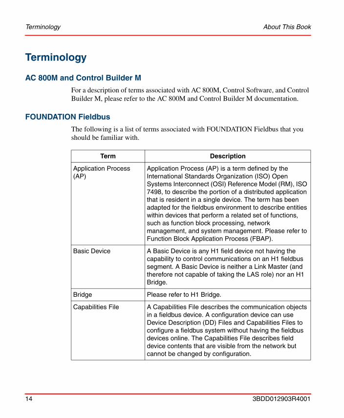
The following is a list of terms associated with FOUNDATION Fieldbus that you should be familiar with.
Term Description
Application Process (AP)
Application Process (AP) is a term defined by the International Standards Organization (ISO) Open Systems Interconnect (OSI) Reference Model (RM), ISO 7498, to describe the portion of a distributed application that is resident in a single device. The term has been adapted for the fieldbus environment to describe entities within devices that perform a related set of functions, such as function block processing, network management, and system management. Please refer to Function Block Application Process (FBAP).
Basic Device A Basic Device is any H1 field device not having the capability to control communications on an H1 fieldbus segment. A Basic Device is neither a Link Master (and therefore not capable of taking the LAS role) nor an H1 Bridge.
Bridge Please refer to H1 Bridge.
Capabilities File A Capabilities File describes the communication objects in a fieldbus device. A configuration device can use Device Description (DD) Files and Capabilities Files to configure a fieldbus system without having the fieldbus devices online. The Capabilities File describes field device contents that are visible from the network but cannot be changed by configuration.
14 3BDD012903R4001
About This Book FOUNDATION Fieldbus
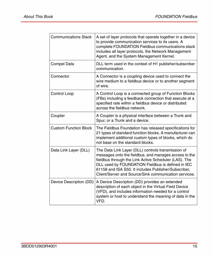
Communications Stack A set of layer protocols that operate together in a device to provide communication services to its users. A complete FOUNDATION Fieldbus communications stack includes all layer protocols, the Network Management Agent, and the System Management Kernel.
Compel Data DLL term used in the context of H1 publisher/subscriber communication.
Connector A Connector is a coupling device used to connect the wire medium to a fieldbus device or to another segment of wire.
Control Loop A Control Loop is a connected group of Function Blocks (FBs) including a feedback connection that execute at a specified rate within a fieldbus device or distributed across the fieldbus network.
Coupler A Coupler is a physical interface between a Trunk and Spur, or a Trunk and a device.
Custom Function Block The Fieldbus Foundation has released specifications for 21 types of standard function blocks. A manufacturer can implement additional custom types of blocks, which do not base on the standard blocks.
Data Link Layer (DLL) The Data Link Layer (DLL) controls transmission of messages onto the fieldbus, and manages access to the fieldbus through the Link Active Scheduler (LAS). The DLL used by FOUNDATION Fieldbus is defined in IEC 61158 and ISA S50. It includes Publisher/Subscriber, Client/Server and Source/Sink communication services.
Device Description (DD) A Device Description (DD) provides an extended description of each object in the Virtual Field Device (VFD), and includes information needed for a control system or host to understand the meaning of data in the VFD.
3BDD012903R4001 15
FOUNDATION Fieldbus About This Book
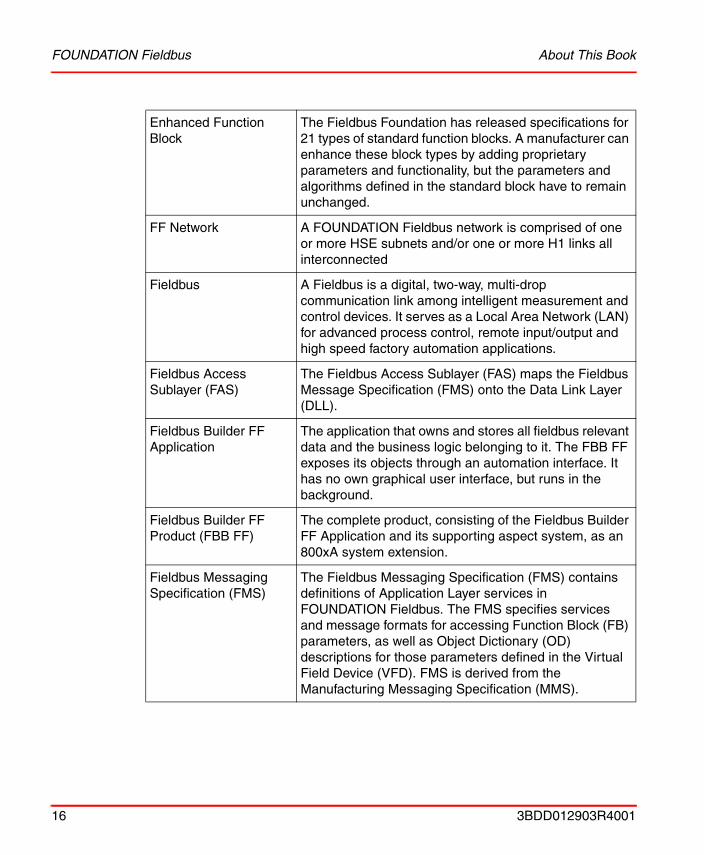
Enhanced Function Block
The Fieldbus Foundation has released specifications for 21 types of standard function blocks. A manufacturer can enhance these block types by adding proprietary parameters and functionality, but the parameters and algorithms defined in the standard block have to remain unchanged.
FF Network A FOUNDATION Fieldbus network is comprised of one or more HSE subnets and/or one or more H1 links all interconnected
Fieldbus A Fieldbus is a digital, two-way, multi-drop communication link among intelligent measurement and control devices. It serves as a Local Area Network (LAN) for advanced process control, remote input/output and high speed factory automation applications.
Fieldbus Access Sublayer (FAS)
The Fieldbus Access Sublayer (FAS) maps the Fieldbus Message Specification (FMS) onto the Data Link Layer (DLL).
Fieldbus Builder FF Application
The application that owns and stores all fieldbus relevant data and the business logic belonging to it. The FBB FF exposes its objects through an automation interface. It has no own graphical user interface, but runs in the background.
Fieldbus Builder FF Product (FBB FF)
The complete product, consisting of the Fieldbus Builder FF Application and its supporting aspect system, as an 800xA system extension.
Fieldbus Messaging Specification (FMS)
The Fieldbus Messaging Specification (FMS) contains definitions of Application Layer services in FOUNDATION Fieldbus. The FMS specifies services and message formats for accessing Function Block (FB) parameters, as well as Object Dictionary (OD) descriptions for those parameters defined in the Virtual Field Device (VFD). FMS is derived from the Manufacturing Messaging Specification (MMS).
16 3BDD012903R4001
About This Book FOUNDATION Fieldbus
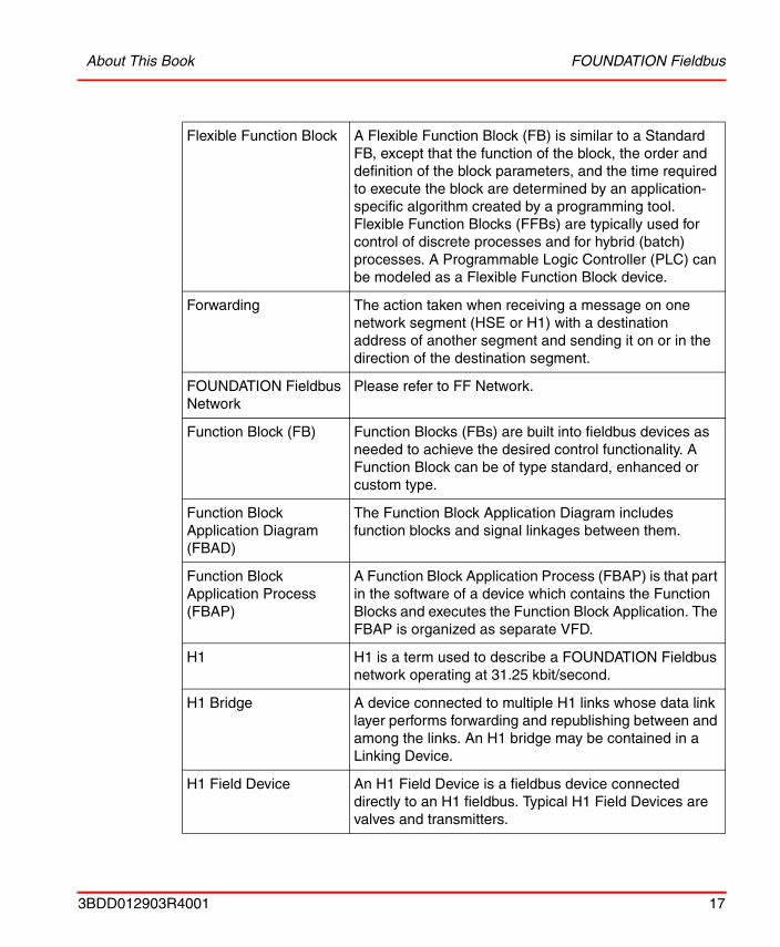
Flexible Function Block A Flexible Function Block (FB) is similar to a Standard FB, except that the function of the block, the order and definition of the block parameters, and the time required to execute the block are determined by an application-specific algorithm created by a programming tool. Flexible Function Blocks (FFBs) are typically used for control of discrete processes and for hybrid (batch) processes. A Programmable Logic Controller (PLC) can be modeled as a Flexible Function Block device.
Forwarding The action taken when receiving a message on one network segment (HSE or H1) with a destination address of another segment and sending it on or in the direction of the destination segment.
FOUNDATION Fieldbus Network
Please refer to FF Network.
Function Block (FB) Function Blocks (FBs) are built into fieldbus devices as needed to achieve the desired control functionality. A Function Block can be of type standard, enhanced or custom type.
Function Block Application Diagram (FBAD)
The Function Block Application Diagram includes function blocks and signal linkages between them.
Function Block Application Process (FBAP)
A Function Block Application Process (FBAP) is that part in the software of a device which contains the Function Blocks and executes the Function Block Application. The FBAP is organized as separate VFD.
H1 H1 is a term used to describe a FOUNDATION Fieldbus network operating at 31.25 kbit/second.
H1 Bridge A device connected to multiple H1 links whose data link layer performs forwarding and republishing between and among the links. An H1 bridge may be contained in a Linking Device.
H1 Field Device An H1 Field Device is a fieldbus device connected directly to an H1 fieldbus. Typical H1 Field Devices are valves and transmitters.
3BDD012903R4001 17
FOUNDATION Fieldbus About This Book
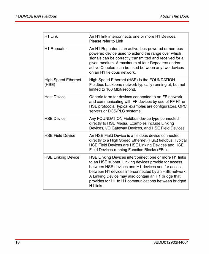
H1 Link An H1 link interconnects one or more H1 Devices. Please refer to Link
H1 Repeater An H1 Repeater is an active, bus-powered or non-bus-powered device used to extend the range over which signals can be correctly transmitted and received for a given medium. A maximum of four Repeaters and/or active Couplers can be used between any two devices on an H1 fieldbus network.
High Speed Ethernet (HSE)
High Speed Ethernet (HSE) is the FOUNDATION Fieldbus backbone network typically running at, but not limited to 100 Mbit/second.
Host Device Generic term for devices connected to an FF network and communicating with FF devices by use of FF H1 or HSE protocols. Typical examples are configurators, OPC servers or DCS/PLC systems.
HSE Device Any FOUNDATION Fieldbus device type connected directly to HSE Media. Examples include Linking Devices, I/O Gateway Devices, and HSE Field Devices.
HSE Field Device An HSE Field Device is a fieldbus device connected directly to a High Speed Ethernet (HSE) fieldbus. Typical HSE Field Devices are HSE Linking Devices and HSE Field Devices running Function Blocks (FBs).
HSE Linking Device HSE Linking Devices interconnect one or more H1 links to an HSE subnet. Linking devices provide for access between HSE devices and H1 devices and for access between H1 devices interconnected by an HSE network. A Linking Device may also contain an H1 bridge that provides for H1 to H1 communications between bridged H1 links.
18 3BDD012903R4001
About This Book FOUNDATION Fieldbus
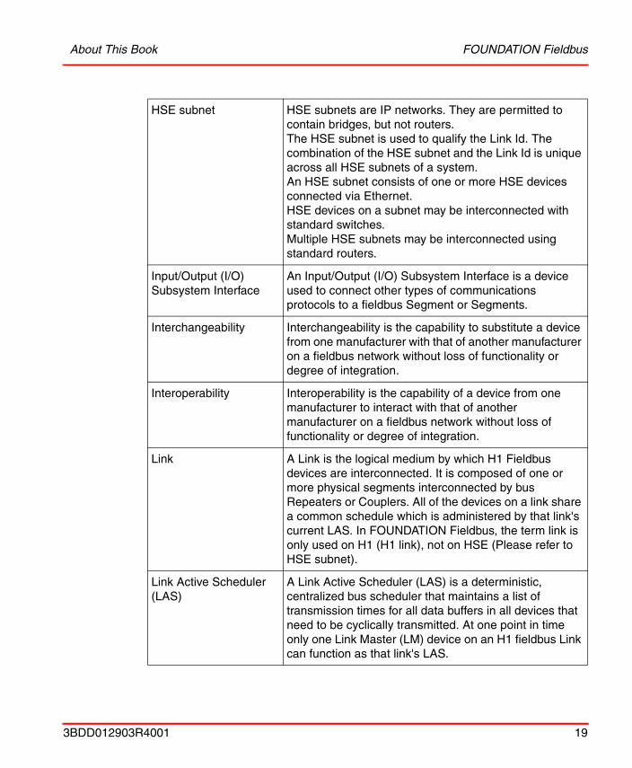
HSE subnet HSE subnets are IP networks. They are permitted to contain bridges, but not routers.The HSE subnet is used to qualify the Link Id. The combination of the HSE subnet and the Link Id is unique across all HSE subnets of a system.An HSE subnet consists of one or more HSE devices connected via Ethernet.HSE devices on a subnet may be interconnected with standard switches.Multiple HSE subnets may be interconnected using standard routers.
Input/Output (I/O) Subsystem Interface
An Input/Output (I/O) Subsystem Interface is a device used to connect other types of communications protocols to a fieldbus Segment or Segments.
Interchangeability Interchangeability is the capability to substitute a device from one manufacturer with that of another manufacturer on a fieldbus network without loss of functionality or degree of integration.
Interoperability Interoperability is the capability of a device from one manufacturer to interact with that of another manufacturer on a fieldbus network without loss of functionality or degree of integration.
Link A Link is the logical medium by which H1 Fieldbus devices are interconnected. It is composed of one or more physical segments interconnected by bus Repeaters or Couplers. All of the devices on a link share a common schedule which is administered by that link's current LAS. In FOUNDATION Fieldbus, the term link is only used on H1 (H1 link), not on HSE (Please refer to HSE subnet).
Link Active Scheduler (LAS)
A Link Active Scheduler (LAS) is a deterministic, centralized bus scheduler that maintains a list of transmission times for all data buffers in all devices that need to be cyclically transmitted. At one point in time only one Link Master (LM) device on an H1 fieldbus Link can function as that link's LAS.
3BDD012903R4001 19

FOUNDATION Fieldbus About This Book
Link Master (LM) A Link Master (LM) is an H1 device containing Link Active Scheduler (LAS) functionality, thus having the ability to control communications on an H1 Link. There must be at least one LM on any H1 Link; only one of the LM devices will take the LAS role.
Link Object A Link Object contains information to link Function Block (FB) Input/Output (I/O) parameters in the same device and between different devices. The Link Object links directly to a Virtual Communications Relationship (VCR) or another Function Block Input/Output parameter. It is also called Linkage Object.
Linkage Object Please refer to Link Object.
Linking Device Please refer to HSE Linking Device.
Macrocyle Please refer to Schedule.
Multiple Input/Output Function Block
Multiple Input/Output Function Blocks increase the efficiency in handling a large amount of signals by combining more than one Input or Output into one Function Block.
Network Management (NM)
Network Management (NM) permits FOUNDATION Network Manager (NMgr, Host) entities to conduct management operations over the network by using Network Management Agents (NMAs) in the devices. Each Network Management Agent (NMA) is responsible for managing the communications within a device. The NMgr and NMA communicate through use of the Fieldbus Messaging Specification (FMS) and Virtual Communications Relationship (VCR).
Network Management Agent (NMA)
Please refer to Network Management.
Network Management Information Base (NMIB)
The NMA VFD contains network and system management information bases (NMIB and SMIB) for the device. The NMIB contains objects related to device Network Management.
20 3BDD012903R4001
About This Book FOUNDATION Fieldbus
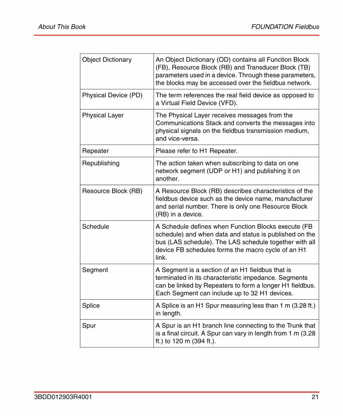
Object Dictionary An Object Dictionary (OD) contains all Function Block (FB), Resource Block (RB) and Transducer Block (TB) parameters used in a device. Through these parameters, the blocks may be accessed over the fieldbus network.
Physical Device (PD) The term references the real field device as opposed to a Virtual Field Device (VFD).
Physical Layer The Physical Layer receives messages from the Communications Stack and converts the messages into physical signals on the fieldbus transmission medium, and vice-versa.
Repeater Please refer to H1 Repeater.
Republishing The action taken when subscribing to data on one network segment (UDP or H1) and publishing it on another.
Resource Block (RB) A Resource Block (RB) describes characteristics of the fieldbus device such as the device name, manufacturer and serial number. There is only one Resource Block (RB) in a device.
Schedule A Schedule defines when Function Blocks execute (FB schedule) and when data and status is published on the bus (LAS schedule). The LAS schedule together with all device FB schedules forms the macro cycle of an H1 link.
Segment A Segment is a section of an H1 fieldbus that is terminated in its characteristic impedance. Segments can be linked by Repeaters to form a longer H1 fieldbus. Each Segment can include up to 32 H1 devices.
Splice A Splice is an H1 Spur measuring less than 1 m (3.28 ft.) in length.
Spur A Spur is an H1 branch line connecting to the Trunk that is a final circuit. A Spur can vary in length from 1 m (3.28 ft.) to 120 m (394 ft.).
3BDD012903R4001 21
FOUNDATION Fieldbus About This Book
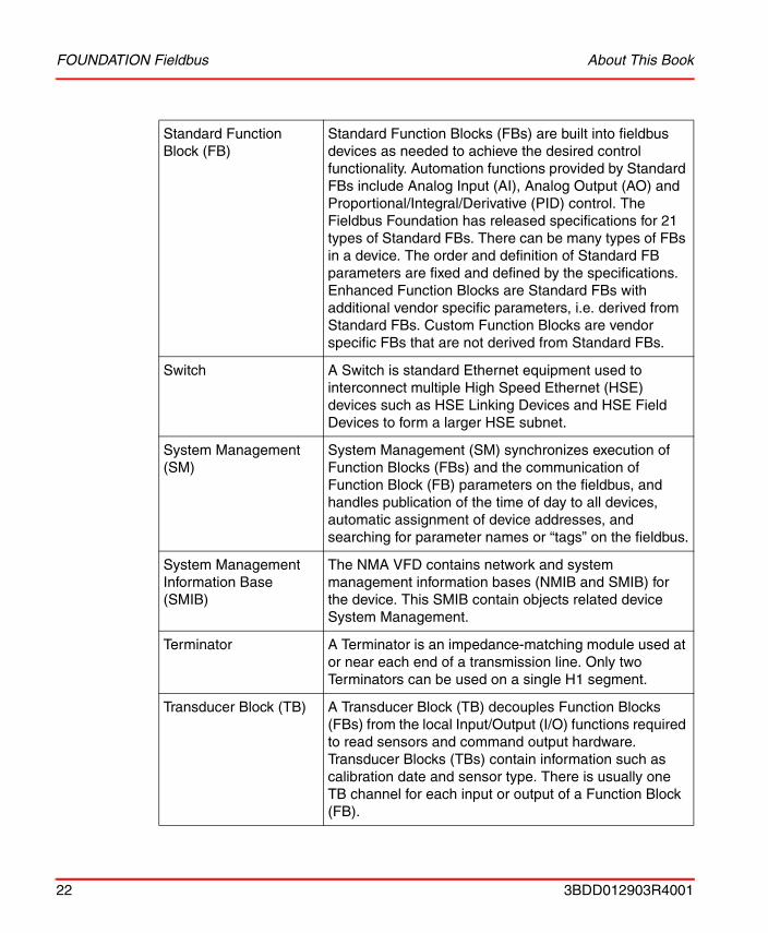
Standard Function Block (FB)
Standard Function Blocks (FBs) are built into fieldbus devices as needed to achieve the desired control functionality. Automation functions provided by Standard FBs include Analog Input (AI), Analog Output (AO) and Proportional/Integral/Derivative (PID) control. The Fieldbus Foundation has released specifications for 21 types of Standard FBs. There can be many types of FBs in a device. The order and definition of Standard FB parameters are fixed and defined by the specifications. Enhanced Function Blocks are Standard FBs with additional vendor specific parameters, i.e. derived from Standard FBs. Custom Function Blocks are vendor specific FBs that are not derived from Standard FBs.
Switch A Switch is standard Ethernet equipment used to interconnect multiple High Speed Ethernet (HSE) devices such as HSE Linking Devices and HSE Field Devices to form a larger HSE subnet.
System Management (SM)
System Management (SM) synchronizes execution of Function Blocks (FBs) and the communication of Function Block (FB) parameters on the fieldbus, and handles publication of the time of day to all devices, automatic assignment of device addresses, and searching for parameter names or “tags” on the fieldbus.
System Management Information Base (SMIB)
The NMA VFD contains network and system management information bases (NMIB and SMIB) for the device. This SMIB contain objects related device System Management.
Terminator A Terminator is an impedance-matching module used at or near each end of a transmission line. Only two Terminators can be used on a single H1 segment.
Transducer Block (TB) A Transducer Block (TB) decouples Function Blocks (FBs) from the local Input/Output (I/O) functions required to read sensors and command output hardware. Transducer Blocks (TBs) contain information such as calibration date and sensor type. There is usually one TB channel for each input or output of a Function Block (FB).
22 3BDD012903R4001
About This Book FOUNDATION Fieldbus
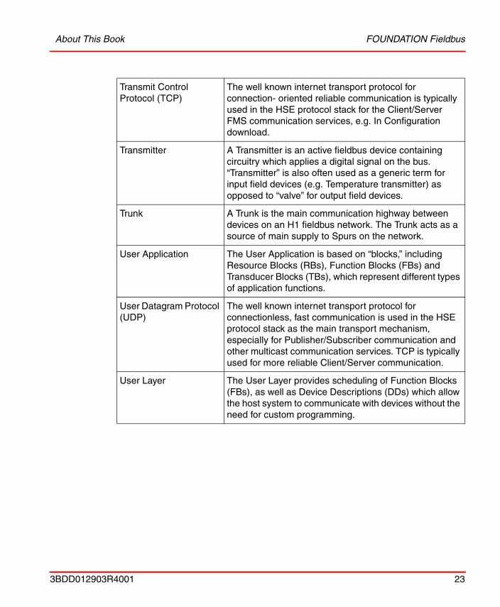
Transmit Control Protocol (TCP)
The well known internet transport protocol for connection- oriented reliable communication is typically used in the HSE protocol stack for the Client/Server FMS communication services, e.g. In Configuration download.
Transmitter A Transmitter is an active fieldbus device containing circuitry which applies a digital signal on the bus. “Transmitter” is also often used as a generic term for input field devices (e.g. Temperature transmitter) as opposed to “valve” for output field devices.
Trunk A Trunk is the main communication highway between devices on an H1 fieldbus network. The Trunk acts as a source of main supply to Spurs on the network.
User Application The User Application is based on “blocks,” including Resource Blocks (RBs), Function Blocks (FBs) and Transducer Blocks (TBs), which represent different types of application functions.
User Datagram Protocol (UDP)
The well known internet transport protocol for connectionless, fast communication is used in the HSE protocol stack as the main transport mechanism, especially for Publisher/Subscriber communication and other multicast communication services. TCP is typically used for more reliable Client/Server communication.
User Layer The User Layer provides scheduling of Function Blocks (FBs), as well as Device Descriptions (DDs) which allow the host system to communicate with devices without the need for custom programming.
3BDD012903R4001 23
Related Documentation About This Book
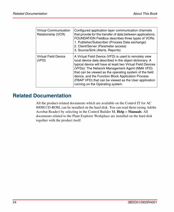
Related DocumentationAll the product-related documents which are available on the Control IT for AC 800M CD-ROM, can be installed on the hard disk. You can read them (using Adobe Acrobat Reader) by selecting in the Control Builder M, Help > Manuals. All documents related to the Plant Explorer Workplace are installed on the hard disk together with the product itself.
Virtual Communication Relationship (VCR)
Configured application layer communication channels that provide for the transfer of data between applications. FOUNDATION Fieldbus describes three types of VCRs:1. Publisher/Subscriber (Process Data exchange)2. Client/Server (Parameter access)3. Source/Sink (Alerts, Reports)
Virtual Field Device (VFD)
A Virtual Field Device (VFD) is used to remotely view local device data described in the object dictionary. A typical device will have at least two Virtual Field Devices (VFDs): The Network Management Agent (NMA VFD) that can be viewed as the operating system of the field device, and the Function Block Application Process (FBAP VFD) that can be viewed as the User application running on the Operating system.
24 3BDD012903R4001
About This Book Related Documentation
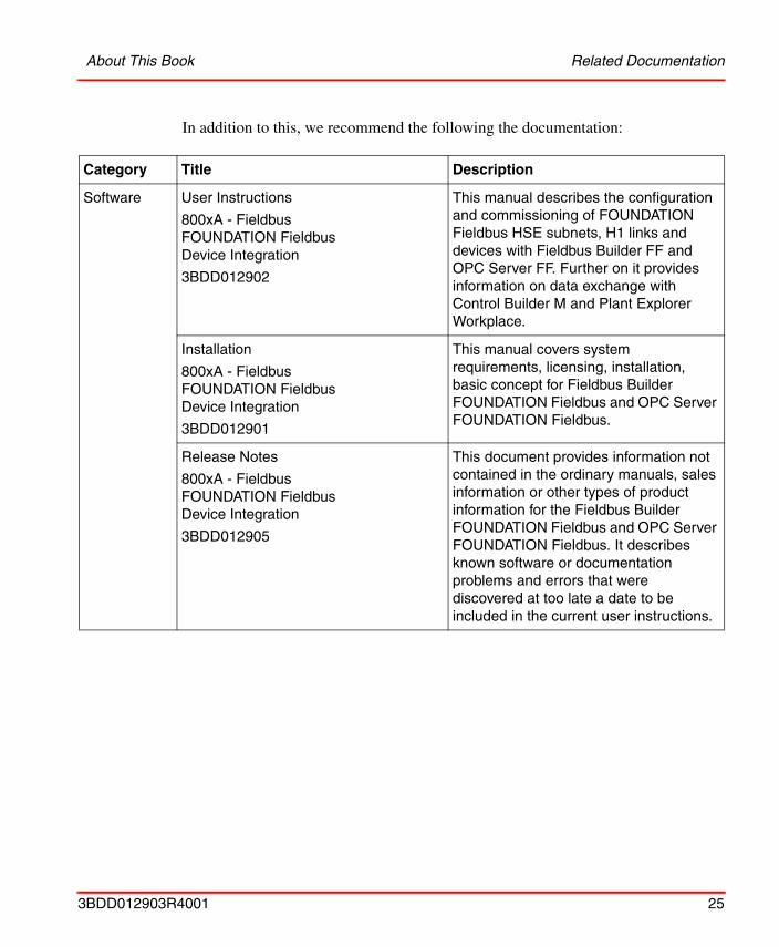
In addition to this, we recommend the following the documentation:
Category Title Description
Software User Instructions
800xA - FieldbusFOUNDATION Fieldbus Device Integration
3BDD012902
This manual describes the configuration and commissioning of FOUNDATION Fieldbus HSE subnets, H1 links and devices with Fieldbus Builder FF and OPC Server FF. Further on it provides information on data exchange with Control Builder M and Plant Explorer Workplace.
Installation
800xA - FieldbusFOUNDATION Fieldbus Device Integration
3BDD012901
This manual covers system requirements, licensing, installation, basic concept for Fieldbus Builder FOUNDATION Fieldbus and OPC Server FOUNDATION Fieldbus.
Release Notes
800xA - FieldbusFOUNDATION Fieldbus Device Integration
3BDD012905
This document provides information not contained in the ordinary manuals, sales information or other types of product information for the Fieldbus Builder FOUNDATION Fieldbus and OPC Server FOUNDATION Fieldbus. It describes known software or documentation problems and errors that were discovered at too late a date to be included in the current user instructions.
3BDD012903R4001 25
Related Documentation About This Book
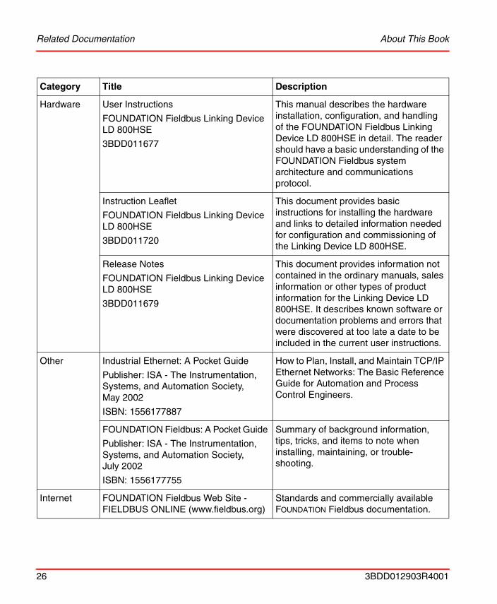
Hardware User Instructions
FOUNDATION Fieldbus Linking Device LD 800HSE
3BDD011677
This manual describes the hardware installation, configuration, and handling of the FOUNDATION Fieldbus Linking Device LD 800HSE in detail. The reader should have a basic understanding of the FOUNDATION Fieldbus system architecture and communications protocol.
Instruction Leaflet
FOUNDATION Fieldbus Linking Device LD 800HSE
3BDD011720
This document provides basic instructions for installing the hardware and links to detailed information needed for configuration and commissioning of the Linking Device LD 800HSE.
Release Notes
FOUNDATION Fieldbus Linking Device LD 800HSE
3BDD011679
This document provides information not contained in the ordinary manuals, sales information or other types of product information for the Linking Device LD 800HSE. It describes known software or documentation problems and errors that were discovered at too late a date to be included in the current user instructions.
Other Industrial Ethernet: A Pocket Guide
Publisher: ISA - The Instrumentation, Systems, and Automation Society, May 2002
ISBN: 1556177887
How to Plan, Install, and Maintain TCP/IP Ethernet Networks: The Basic Reference Guide for Automation and Process Control Engineers.
FOUNDATION Fieldbus: A Pocket Guide
Publisher: ISA - The Instrumentation, Systems, and Automation Society, July 2002
ISBN: 1556177755
Summary of background information, tips, tricks, and items to note when installing, maintaining, or trouble-shooting.
Internet FOUNDATION Fieldbus Web Site - FIELDBUS ONLINE (www.fieldbus.org)
Standards and commercially available FOUNDATION Fieldbus documentation.
Category Title Description
26 3BDD012903R4001
Section 1 Introduction General Overview
Section 1 Introduction
General OverviewFOUNDATION Fieldbus (FF) is a fieldbus protocol based on international standards and designed for applications in the manufacturing industry, process automation and buildings automation. The Fieldbus Foundation publishes the guidelines for this fieldbus standard.
FF defines two communication profiles, H1 and HSE. The H1 profile allows a transmission rate of 31.25 kbit/s. It is preferably used for direct communication between field devices in one link (H1 link). The HSE profile with a transmission rate of 10 or 100 Mbit/s serves first and foremost as a powerful backbone for the link between H1 segments. The first devices that are already available on the market and support the HSE profile are FF Linking Devices (e.g. LD 800HSE). They serve as a gateway between the field devices on the H1 segments and the HSE backbone.
The FOUNDATION Fieldbus is linked to the AC 800M via the high-performance HSE bus using FF Linking Devices.
More detailed information on the HSE profile can be found in the FF specifications. The fundamental concepts behind HSE are explained in the FF specifications System Architecture (FF-581) and HSE Profiles (FF-941).
The FF subsystem consists of FF Linking Devices (LD), which communicate with one another using the HSE protocol. An FF Linking Device usually provides more than one FOUNDATION Fieldbus H1 segment (H1 link). FF Linking Devices with a device class of 42c allow process data that have been published cyclically on the subsidiary H1 segments to be “republished” on the HSE segment. By using HSE republishing, it is possible to configure cyclical communication between field devices on different H1 segments and devices on the HSE segment. The FOUNDATION Fieldbus HSE and H1network and the devices are configured with the Fieldbus Builder FOUNDATION Fieldbus.
The FF subsystem is interfaced to the IEC 61131 controller (AC 800M) using the FF/HSE module CI860 in the AC 800M. From the perspective of FF the FF/HSE module is an HSE device which participates in the HSE communication. FF Linking
3BDD012903R4001 27
Prerequisites and Requirements Section 1 Introduction
Devices operate as gateways between the AC 800M and the field devices on the H1 segments both for the configuration data of the field devices and for the process data which is exchanged cyclically between AC 800M and the field devices.
Prerequisites and RequirementsThe following software versions are required:
• Control Builder M Professional must be version 4.0.
• 800xA System and Plant Explorer Workplace must be system version 4.0.
• Fieldbus Builder FOUNDATION Fieldbus and OPC Server FOUNDATION Fieldbus must be version 4.0.
For detailed information please refer to the appropriate Release Notes.
28 3BDD012903R4001
Section 2 Functional Description
The following sections provide detailed technical information on the FOUNDATION Fieldbus HSE implementation for Control Builder M.
OverviewThe FOUNDATION Fieldbus HSE implementation adds FF HSE support to Control Builder M and AC 800M. This includes the new FF HSE CEX bus module CI860, FF HSE support for AC 800M and Control Builder M, Fieldbus Builder FF, FF OPC server, and integration between these components.
Configuration is done from Plant Explorer Workplace with use of the two aspect systems Fieldbus Builder FOUNDATION Fieldbus (Fieldbus Builder FF) and Control Builder M. The Fieldbus Builder FF is used for configuration of the FF application, and the Control Builder M is used for configuration of the IEC 61131 application. Double data entry is avoided by the connection of both tools.
The FF H1 solution with the CI852 is not affected and will not be discussed further in this document.
3BDD012903R4001 29
Overview Section 2 Functional Description
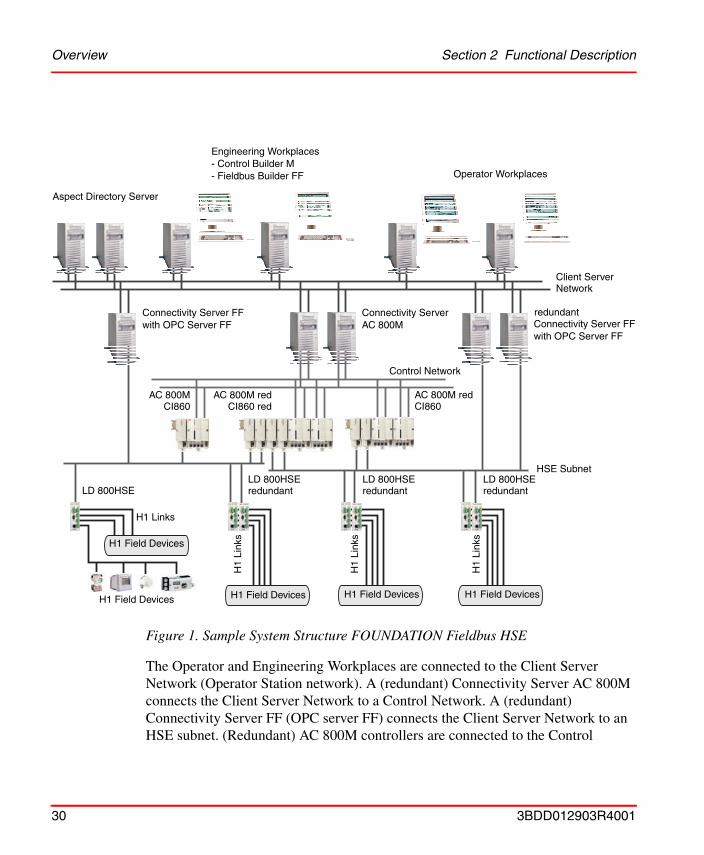
The Operator and Engineering Workplaces are connected to the Client Server Network (Operator Station network). A (redundant) Connectivity Server AC 800M connects the Client Server Network to a Control Network. A (redundant) Connectivity Server FF (OPC server FF) connects the Client Server Network to an HSE subnet. (Redundant) AC 800M controllers are connected to the Control
Figure 1. Sample System Structure FOUNDATION Fieldbus HSE
Operator Workplaces
Engineering Workplaces- Control Builder M- Fieldbus Builder FF
Aspect Directory Server
Connectivity Server FFwith OPC Server FF
Connectivity Server FFwith OPC Server FF
Connectivity Server AC 800M
Control Network
CI860AC 800M
CI860AC 800M red
CI860 red
HSE Subnet
LD 800HSELD 800HSEredundant
LD 800HSEredundant
LD 800HSEredundant
H1 Links
H1
Link
s
H1
Link
s
H1
Link
s
H1 Field Devices
H1 Field Devices H1 Field Devices H1 Field DevicesH1 Field Devices
Client ServerNetwork
AC 800M red
redundant
30 3BDD012903R4001
Section 2 Functional Description Configuration Data
Network, CI860 modules connect the controller to an HSE subnet. A controller can have up to twelve CI860 modules connected up to twelve different HSE subnets. HSE FF devices and HSE-H1 Linking Devices can be connected to the FF HSE subnet. Below the HSE-H1 Linking Devices, H1 links are connected.
A control application can be distributed over AC 800M controllers and FF devices. The junction between the IEC 61131 world and the FF world is the DPM (dual port memory) in the CI860: In the DPM variables defined in the IEC 61131 applications are mapped to FF signals connected to FF function block in FF devices. In the Control Builder M these FF signals are represented as I/O channels. Two different data types exist for the FF signals: analog and discrete. These are mapped to AnalogIn, AnalogOut, DiscreteIn, and DiscretOut channels.
Configuration Data The whole configuration data of the CI860 including the FF configuration is downloaded to the AC 800M from the Control Builder M during the normal download procedure.
This data includes information about FF signals connected to the DPM in the CI860. These connections are set up in the Fieldbus Builder FF and are fetched by the Control Builder M before download to the controller. All downloads to the CI860 are handled by the Control Builder M. There is no need for a communication between the Fieldbus Builder FF and the CI860. All FF configuration data of other FF devices is downloaded by the Fieldbus Builder FF. If the Client Server Network and HSE network are separated, the FF OPC server is used to route the Fieldbus Builder FF communication to the HSE network. The AC 800M does not provide any routing mechanism for that.
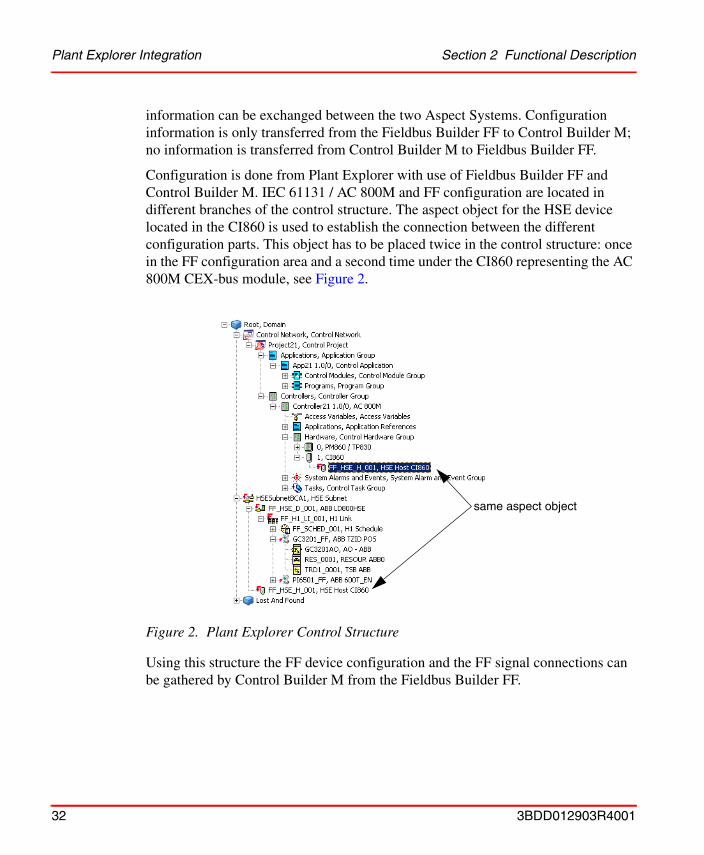
Plant Explorer IntegrationA typical Plant Explorer Workplace control structure including AC 800M and FF HSE is shown in Figure 2. Two aspect systems Fieldbus Builder FF and Control Builder M must be installed on the workstations running Plant Explorer Workplace.
The two parts of the configuration although they are part of the same control structure are handled by different Aspect Systems: one by the Control Builder M and one by the Fieldbus Builder FF. These parts are linked so that configuration
3BDD012903R4001 31
Plant Explorer Integration Section 2 Functional Description
information can be exchanged between the two Aspect Systems. Configuration information is only transferred from the Fieldbus Builder FF to Control Builder M; no information is transferred from Control Builder M to Fieldbus Builder FF.
Configuration is done from Plant Explorer with use of Fieldbus Builder FF and Control Builder M. IEC 61131 / AC 800M and FF configuration are located in different branches of the control structure. The aspect object for the HSE device located in the CI860 is used to establish the connection between the different configuration parts. This object has to be placed twice in the control structure: once in the FF configuration area and a second time under the CI860 representing the AC 800M CEX-bus module, see Figure 2.
Using this structure the FF device configuration and the FF signal connections can be gathered by Control Builder M from the Fieldbus Builder FF.
Figure 2. Plant Explorer Control Structure
same aspect object
32 3BDD012903R4001
Section 2 Functional Description Handling of Configuration Changes
Handling of Configuration ChangesThe Control Builder M itself can only track changes done in the Control Builder environment. Changes in the Fieldbus Builder FF cannot be tracked by the CI860 directly.
After a successful download the Control Builder M stores the downloaded CI860 configuration. During the next download sequence the last successfully downloaded CI860 configuration is compared with the current CI860 configuration requested from the Fieldbus Builder FF. If changes are detected the new CI860 configuration is returned to the Control Builder M, which will download the CI860 configuration to the controller.
The downloaded CI860 configuration is also automatically checked into the aspect directory, so that the data is stored persistently.
During download of the CI860 configuration the IEC 61131 user application will not be stopped.
Data TypesThe DPM in the CI860 contains a fixed number of channels of the four different channel types. AnalogIn (IW), AnalogOut (QW), DiscreteIn (IX), and DiscreteOut (QX), see Figure 3 to Figure 6. The analog FF data type DS-65 is mapped to the RealIO data type of the AC 800M, the discrete FF data type DS-66 can contain binary information but also up to 256 states (one byte). For these different usages two AC 800M data types can be mapped to the discrete FF signal: The BoolIO for binary usage and the DwordIO for the full usage of all possible values. The CI860 provides these two possibilities for a discrete channel.
3BDD012903R4001 33
Data Types Section 2 Functional Description
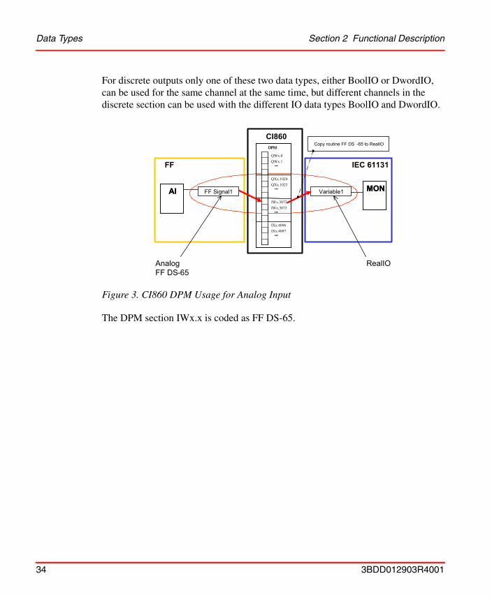
For discrete outputs only one of these two data types, either BoolIO or DwordIO, can be used for the same channel at the same time, but different channels in the discrete section can be used with the different IO data types BoolIO and DwordIO.
The DPM section IWx.x is coded as FF DS-65.
Figure 3. CI860 DPM Usage for Analog Input
FF IEC 61131
FF Signal1 MON MON AI AI Variable1
RealIO Analog FF DS - 65
CI860DPM
QWx.0QWx.1
...
QXx.1024QXx.1025
...
IWx.3072IWx.3073
...
IXx.4096IXx.4097
...
DPM
...
...
...
...
Copy routine FF DS -65 to RealIO
34 3BDD012903R4001
Section 2 Functional Description Data Types
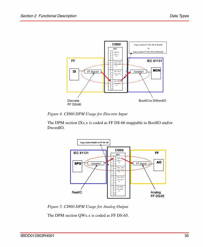
The DPM section IXx.x is coded as FF DS-66 mappable to BoolIO and/or DwordIO.
The DPM section QWx.x is coded as FF DS-65.
Figure 4. CI860 DPM Usage for Discrete Input
Figure 5. CI860 DPM Usage for Analog Output
FF IEC 61131
FF Signal1 MON MON DI DI Variable1
BoolIO or DWordIO Discrete FF DS - 66
Copy routine FF DS - 66 to BoolIO or
Copy routine FF DS - 66 to DWordIO
CI860DPM
QWx.0QWx.1
...
QXx.1024QXx.1025
...
IWx.3072IWx.3073
...
IXx.4096IXx.4097
...
DPM
...
...
...
...
IEC 61131 FF
Variable1 AO SPG FF Signal
RealIO Analog FF DS - 65
Copy routine RealIO to FF DS -65
FF
Variable1 AO AO SPG SPG FF Signal
RealIO Analog FF DS - 65
Copy routine RealIO to FF DS -65
CI860DPM
QWx.0QWx.1
...
QXx.1024QXx.1025
...
IWx.3072IWx.3073
...
IXx.4096IXx.4097
...
DPM
...
...
...
...
3BDD012903R4001 35
Specific Control Modules Section 2 Functional Description
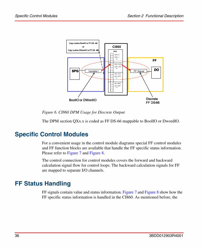
The DPM section QXx.x is coded as FF DS-66 mappable to BoolIO or DwordIO.
Specific Control ModulesFor a convenient usage in the control module diagrams special FF control modules and FF function blocks are available that handle the FF specific status information. Please refer to Figure 7 and Figure 8.
The control connection for control modules covers the forward and backward calculation signal flow for control loops. The backward calculation signals for FF are mapped to separate I/O channels.
FF Status HandlingFF signals contain value and status information. Figure 7 and Figure 8 show how the FF specific status information is handled in the CI860. As mentioned before, the
Figure 6. CI860 DPM Usage for Discrete Output
FF
Variable1 DO SPG FF Signal
BoolIO or DWordIO Discrete FF DS - 66
Copy routine BoolIO to FF DS -66
or
Copy routine DWordIO to FF DS -66
FF
Variable1 DO DO SPG SPG FF Signal
BoolIO or DWordIO Discrete FF DS - 66
Copy routine BoolIO to FF DS -66
or
Copy routine DWordIO to FF DS -66
-
or
-66 CI860
DPM
QWx.0QWx.1
...
QXx.1024QXx.1025
...
IWx.3072IWx.3073
...
IXx.4096IXx.4097
...
DPM
...
...
...
...
36 3BDD012903R4001
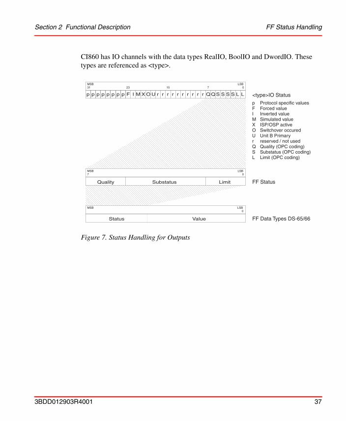
Section 2 Functional Description FF Status Handling
CI860 has IO channels with the data types RealIO, BoolIO and DwordIO. These types are referenced as <type>.
Figure 7. Status Handling for Outputs
p
Quality
Status Value
Substatus Limit
p p p p p p p F I M X O U r r r r r r r r r r QQS S S S L L <type>IO Status
FF Status
FF Data Types DS-65/66
31 0
0
0
23 15 7
7
MSB
MSB
MSB
LSB
LSB
LSB
p Protocol specific valuesF Forced valueI Inverted valueM Simulated valueX ISP/OSP activeO Switchover occuredU Unit B Primaryr reserved / not usedQ Quality (OPC coding)S Substatus (OPC coding)L Limit (OPC coding)
3BDD012903R4001 37
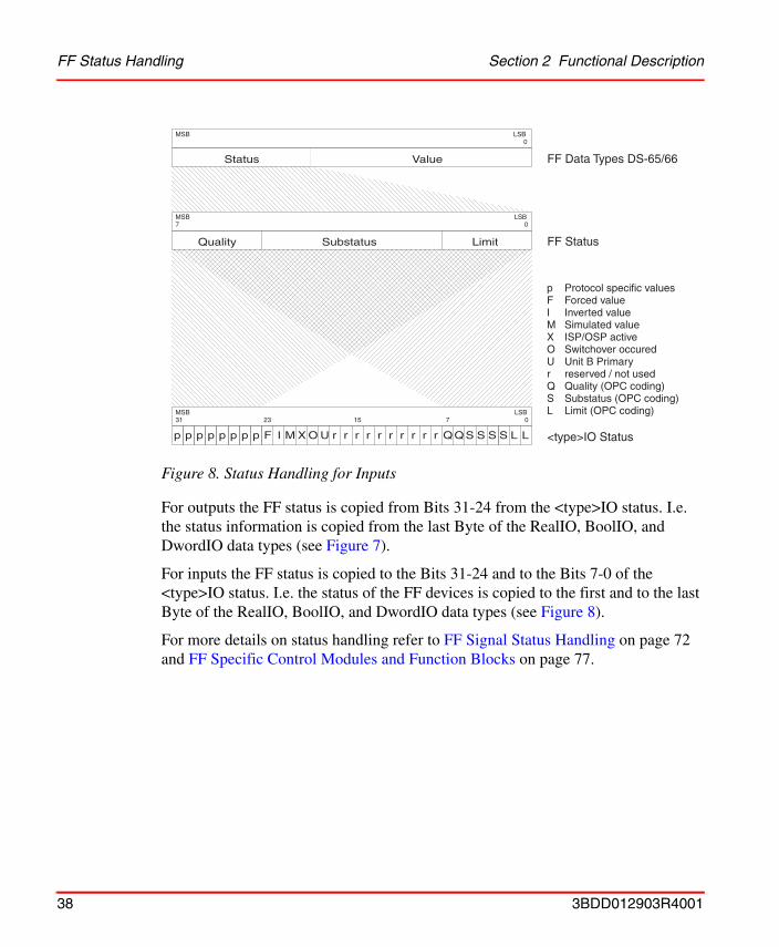
FF Status Handling Section 2 Functional Description
For outputs the FF status is copied from Bits 31-24 from the <type>IO status. I.e. the status information is copied from the last Byte of the RealIO, BoolIO, and DwordIO data types (see Figure 7).
For inputs the FF status is copied to the Bits 31-24 and to the Bits 7-0 of the <type>IO status. I.e. the status of the FF devices is copied to the first and to the last Byte of the RealIO, BoolIO, and DwordIO data types (see Figure 8).
For more details on status handling refer to FF Signal Status Handling on page 72 and FF Specific Control Modules and Function Blocks on page 77.
Figure 8. Status Handling for Inputs
p
Quality
Status Value
Substatus Limit
p p p p p p p F I M X O U r r r r r r r r r r QQS S S S L L <type>IO Status
FF Status
FF Data Types DS-65/66
31 0
0
0
23 15 7
7
MSB
MSB
MSB
LSB
LSB
LSB
p Protocol specific valuesF Forced valueI Inverted valueM Simulated valueX ISP/OSP activeO Switchover occuredU Unit B Primaryr reserved / not usedQ Quality (OPC coding)S Substatus (OPC coding)L Limit (OPC coding)
38 3BDD012903R4001
Section 3 System Structure
The following sections provide necessary information for the design, layout, and dimensioning of FOUNDATION Fieldbus HSE networks with Control Builder M, Fieldbus Builder FOUNDATION Fieldbus and AC 800M.
ComponentsClient Server Network
Network to which engineering and operator workplaces as well as servers are connected.
Engineering Workplace800xA engineering workplace running Control Builder M and/or Fieldbus Builder FF.
Fieldbus Builder FFFieldbus Builder FOUNDATION Fieldbus, Engineering Tool for Configuration, Commissioning of FOUNDATION Fieldbus networks including H1 and HSE.
Control Builder MEngineering tool for configuration of AC 800M hardware and applications.
Operator Workplace800xA operator workplace for process visualization and operation.
Connectivity Server FFConnectivity server running OPC Server FOUNDATION Fieldbus.
OPC Server FFOPC Server FOUNDATION Fieldbus, OPC Server for FOUNDATION Fieldbus.
3BDD012903R4001 39
Components Section 3 System Structure
Connectivity Server AC 800MConnectivity server running OPC Server for AC 800M.
Control Network 10 Mbit/s Ethernet Network used to connect controllers, operator stations, engineering workplaces, servers, etc.
AC 800M AC 800M controller: Hardware platform to which individual hardware modules may be connected and which, depending on the specific module configuration and operating system selected, can be programmed to perform multiple functions.
CI860 FOUNDATION Fieldbus HSE Communication Interface Module CI860 for the AC 800M controller.
LD 800HSE FOUNDATION Fieldbus Linking Device LD 800HSE. Gateway between four FF H1 networks and FF HSE suited for redundant use.
HSE FOUNDATION Fieldbus High Speed Ethernet (HSE) protocol, used as backbone network. Typically running at, but not being limited to 100 Mbit/second Ethernet.
H1 FOUNDATION Fieldbus H1 protocol using 31.25 kbit/s network physics.
40 3BDD012903R4001
Section 3 System Structure Components
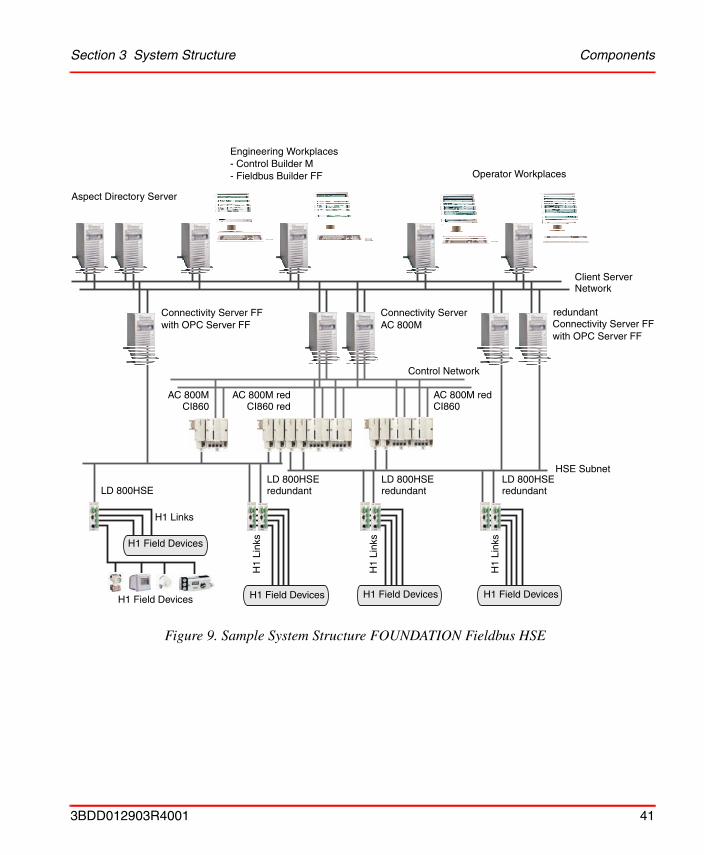
Figure 9. Sample System Structure FOUNDATION Fieldbus HSE
Operator Workplaces
Engineering Workplaces- Control Builder M- Fieldbus Builder FF
Aspect Directory Server
Connectivity Server FFwith OPC Server FF
Connectivity Server FFwith OPC Server FF
Connectivity Server AC 800M
Control Network
CI860AC 800M
CI860AC 800M red
CI860 red
HSE Subnet
LD 800HSELD 800HSEredundant
LD 800HSEredundant
LD 800HSEredundant
H1 Links
H1
Link
s
H1
Link
s
H1
Link
s
H1 Field Devices
H1 Field Devices H1 Field Devices H1 Field DevicesH1 Field Devices
Client ServerNetwork
AC 800M red
redundant
3BDD012903R4001 41

General Section 3 System Structure
General• Multiple HSE subnets may be connected to a system.
• The CPU module of the AC 800M controller must be connected to the Control Network.
• The FOUNDATION Fieldbus HSE Communication Interface Modules CI860 in the AC 800M controller must be connected to an HSE subnet.
• Up to twelve FOUNDATION Fieldbus HSE Communication Interface Modules CI860 may be connected to one AC 800M controller.
• The FOUNDATION Fieldbus HSE Communication Interface Module CI860 may be used in redundant controllers and it supports module redundancy.
• The Linking Device LD 800HSE connects H1 links to an HSE subnet. The LD 800HSE can be used in redundant configuration.
• FOUNDATION Fieldbus HSE subnets should be physically separated from other networks as FOUNDATION Fieldbus HSE multicasts cause high load on the network.
• OPC Server FF provides tool routing functionality.
– If the Client Server Network and FOUNDATION Fieldbus HSE subnet(s) are separated from each other, which is the recommended configuration, the Connectivity Server(s) running OPC Server FF are required to provide tool routing functionality for the workplaces running Fieldbus Builder FF so that these can access the FF subnet(s).
– If the Client Server Network and a FOUNDATION Fieldbus HSE subnet are separated from each other without a Connectivity Server running OPC Server FF, the workplace running Fieldbus Builder FF needs to be connected directly to the HSE subnet and to the Client Server Network. This is not recommended and should be used in small configurations only. Only a single HSE subnet can be configured.
– If Client Server Network and a FOUNDATION Fieldbus HSE subnet are not separated from each other, which is not recommended in production
Fieldbus Builder FF provides tool routing only if no OPC server FF has been added to the HSE subnet configuration in Fieldbus Builder FF.
42 3BDD012903R4001
Section 3 System Structure Client Server Network
environments, the Fieldbus Builder FF provides tool routing functionality if no OPC Server FF is configured.
Client Server NetworkThe following components are connected to the Client Server Network:
• Aspect Directory Server,
• Plant Explorer Workplaces with Control Builder M and Fieldbus Builder FF,
• Operator Workplaces,
• Connectivity Server(s) with OPC Server AC 800M,
• Connectivity Server(s) with OPC Server FF.
Control Network
• The following components are connected to the Control Network:
– AC 800M controller(s),
– Connectivity Server(s) with OPC Server AC 800M,
• For further information please refer to Control Builder M and AC 800M documentation.
HSE Subnet
FOUNDATION Fieldbus HSE subnets must never be combined with the controller network. FOUNDATION Fieldbus HSE multicasts create too much load on the controller network. Please take this into account when planning and dimensioning the network structure.
FOUNDATION Fieldbus HSE subnets must never be combined with the controller network. FOUNDATION Fieldbus HSE multicasts create too much load on the controller network. Please take this into account when planning and dimensioning the network structure.
3BDD012903R4001 43
H1 Links Section 3 System Structure
• The following components are connected to the HSE subnet:
– FOUNDATION Fieldbus HSE Communication Interface Modules CI860,
– Connectivity Server(s) with OPC Server FF,
– FOUNDATION Fieldbus Linking Device(s) LD 800HSE.
• Multiple FOUNDATION Fieldbus Linking Devices can be used in an HSE subnet. It is recommended that a maximum of 15 Linking Devices are connected to a single HSE subnet.
• Multiple FF HSE Host Devices like the CI860 may be connected to an HSE subnet. For Communication Interface redundancy two CI860 are connected to one controller AC 800M and are configured to work as a redundant pair. Both CI860 of a redundant pair must be connected to the same HSE subnet (see Figure 9).
• HSE subnets are based on the Ethernet standard. Therefore standard Ethernet components can be used to build up an HSE subnet.
• All components used in an HSE subnet must be capable of handling multicasts as FOUNDATION Fieldbus uses multicast.
• During network dimensioning for HSE subnets the additional load caused due to multicasts has to be taken into account.
H1 Links• Per FOUNDATION Fieldbus Linking Device LD 800HSE up to 4 FF H1 Links
may be connected.
• Experience has shown that a maximum of 16devices should be connected per FF H1 Link. Please refer to Dimensioning Limits, Linking Device on page 45.
Standard routers without multicast routing functionality may not be used.
When calculating the maximum number of H1 devices that may be connected to an H1 link, the power consumption of the individual H1 devices must be taken into account as well as cable lengths and the cable type.
44 3BDD012903R4001
Section 3 System Structure Dimensioning Guidelines
Dimensioning Guidelines
General Recommendations
• Standard structures are shown in the sample structures. Please refer to Figure 9.
• Client Server Network and HSE subnets must be separated in production environments.
• Project planning for mid-sized to large networks should allow for Ethernet redundancy to increase the availability. On the HSE subnets this can be realized for example by ring structure from Hirschmann.
• The use of switches is recommended. However only switches that pass multicasts may be used. Thereby no segmentation with respect to multicasts is caused whereas switches segment for standard Ethernet errors (continuous signal, packets exceeding allowed width) and keeps errors away from other segments. Further on switches allow for conversion between TX (Twisted Pair) and FX (Fibre Optic) and for conversion from 10 MBit/s to 100 MBit/s and vice versa.
FOUNDATION Fieldbus Communication
Dimensioning Limits, Linking Device
• Please refer to the LD 800HSE Linking Device documentation.
Dimensioning Limits, FOUNDATION Fieldbus HSE Communication Interface Module CI860
FOUNDATION Fieldbus HSE Communication Interface Module CI860, HSE level:
• The CI860 can handle a maximum of 1000 VCRs, i.e. 1000 connections to I/O channels can be handled and therefore 1000 FF signals can be communicated with the CI860.
• For each CI860 a maximum of 500 signals per second can be read/written.
FOUNDATION Fieldbus HSE Communication Interface Module CI860, controller level:
3BDD012903R4001 45
FOUNDATION Fieldbus Communication Section 3 System Structure
• Please refer to the AC 800M hardware documentation.
Dimensioning Limits, FF HSE Communication Configuration
Control Builder M, CI860 Configuration:
In Control Builder M variables can be mapped to CI860 channels. Analog channels are mapped to the RealIO data type whereas discrete channels can be mapped to BoolIO and DwordIO data types. The number of CI860 channels to which variables can be mapped is limited to the following numbers:
• 1000 channels of RealIO type for analog inputs,
• 500 channels of RealIO type for analog outputs,
• 500 channels of BoolIO type and 500 channels of DwordIO type for discrete inputs,
• 250 channels of BoolIO type and 250 channels of DwordIO type for discrete outputs.
The overall number of channels is limited to 1000 due to the limited number of VCRs being available on the HSE side.
Fieldbus Builder FF, CI860 Configuration:
In Fieldbus Builder FOUNDATION Fieldbus signals can be mapped to CI860 channels in the HSE Host Device CI860 object. For numbers and detailed information please refer to Fieldbus Builder FF documentation: ’800xA - Fieldbus, FOUNDATION Fieldbus Configuration’.
46 3BDD012903R4001
Section 4 Configuration
This section describes the configuration of FOUNDATION Fieldbus HSE with the Control Builder M and the interaction with the Fieldbus Builder FF.
Overview
Connectivity Function
A typical Plant Explorer Workplace control structure including AC 800M and FF HSE is shown in Figure 2. Two aspect systems Fieldbus Builder FF and Control Builder M must be installed on the workstations running Plant Explorer Workplace.
The Operator and Engineering Workplaces are connected to the Client Server Network (Operator Station network). A (redundant) Connectivity Server AC 800M connects the Client Server Network to a Control Network. A (redundant) Connectivity Server FF (OPC server FF) connects the Client Server Network to an HSE subnet. (Redundant) AC 800M controllers are connected to the Control Network, CI860 modules connect the controller to an HSE subnet. A controller can have up to twelve CI860 modules connected up to twelve different HSE subnets. HSE FF devices and HSE-H1 Linking Devices can be connected to the FF HSE subnet. Below the HSE-H1 Linking Devices, H1 links are connected.
The two parts of the configuration although they are part of the same control structure are handled by different Aspect Systems: one by the Control Builder M and one by the Fieldbus Builder FF. These parts are linked so that configuration information can be exchanged between the two Aspect Systems. Configuration information is only transferred from the Fieldbus Builder FF to Control Builder M; no information is transferred from Control Builder M to Fieldbus Builder FF.
3BDD012903R4001 47
Configuration Workflow Section 4 Configuration
Configuration
The user can start either with the Control Builder M configuration or the Fieldbus Builder FF configuration.
Configuration Workflow
This section describes the workflow and the order of the individual steps that have to be carried out to access FF data from Control Builder M. As the configuration is done with two different Aspect Systems it is up to the user to start configuration with the Control Builder M or with the Fieldbus Builder FF.
The Control Builder M is used to configure the CI860 module as well as to do the application programming. The configuration for the CI860 is handled as for any other Communication Interface. The I/O channels of the CI860 are visible in the Hardware Editor. The Fieldbus Builder FF configuration covers the hardware configuration and the function block application. For the link structure of HSE subnets and H1 links, instances of the device classes imported from capabilities files and device description files must be placed.
The FF HSE configuration involves the following steps. It is assumed that you have the Plant Explorer Workplace, Control Builder M and Fieldbus Builder FF installed. Apart from this, it is required that a system created with the configuration wizard is running. In addition, it is assumed that all required hardware has been installed.
1. Configure your networks, i.e. the Client Server Network, the Control Network and HSE subnets. Please refer to Network Configuration on page 49.
As a good starting point it is recommended to configure the CI860 FF HSE Host object in Fieldbus Builder FF and to define the signals that shall be communicated with the CI860, i.e the channel layout, as well as to configure the CI860 hardware with Control Builder M. Next this partial HSE subnet configuration needs to be uploaded to the Plant Explorer and the HSE subnet needs to be connected to the CI860. Doing so the CI860 configuration is available to Control Builder M.
Then both configurations, the Fieldbus Builder FF HSE subnet configuration on the one hand and the Control Builder M application on the other hand can be finalized.
48 3BDD012903R4001
Section 4 Configuration Network Configuration
2. Configure the AC 800M controller hardware. This includes the configuration of the FOUNDATION Fieldbus HSE Communication Interface Module CI860. Please refer to AC 800M Controller Hardware Configuration on page 54.
3. Configure an HSE subnet. Please refer to HSE Subnet Configuration on page 57.
4. Connect an HSE subnet. Please refer to HSE Subnet Connection on page 59.
5. LD 800HSE Linking Device configuration. Please refer to the Fieldbus Builder FF documentation: ’800xA - Fieldbus, FOUNDATION Fieldbus Configuration’.
6. FF HSE Host object configuration. Please refer to the Fieldbus Builder FF documentation: ’800xA - Fieldbus, FOUNDATION Fieldbus Configuration’
7. H1 Link configuration. Please refer to the Fieldbus Builder FF documentation: ’800xA - Fieldbus, FOUNDATION Fieldbus Configuration’.
8. H1 Device configuration. Please refer to the Fieldbus Builder FF documentation: ’800xA - Fieldbus, FOUNDATION Fieldbus Configuration’.
9. Configure your Control Builder M application(s). Please refer to Section 5, Application Programming.
10. Commissioning the HSE subnet. Please refer to the Fieldbus Builder FF documentation: ’800xA - Fieldbus, FOUNDATION Fieldbus Configuration’.
11. Going Online. Please refer to Section 6, Download and Online Mode.
Network ConfigurationThe following sections describe the network configuration for the systems and components involved. Figure 9 on page 41 shows a sample system structure. Please be aware that this document does not describe how to configure the Windows operation system. Some software needs additional configuration which is described in the following sections. If the configuration is described in detail in other manuals you will find a reference to the documentation. The Windows network configuration must be carried out before following the configuration as described.
3BDD012903R4001 49
Client Server Network and Control Network Section 4 Configuration
Client Server Network and Control Network
In order to get communication between all involved components and software packages, you must ensure the network(s) is (are) properly configured. IP addresses must be unique within a subnet. Select IP addresses that match your subnet mask settings. If you are not sure which settings to select, contact your network administrator for advice.
Redundant Network Configuration
For redundant network configurations please refer to Plant Explorer Workplace and Control Builder M documentation to get detailed information on setting up RNRP.
Setting the IP Addresses and Subnet Masks for Plant Explorer Workplaces
Please refer to the Plant Explorer Workplace documentation.
Setting the IP Addresses and Subnet Masks for Control Builder M
Please refer to the Control Builder M documentation.
Setting the IP Addresses and Subnet Masks for Fieldbus Builder FF
The Fieldbus Builder FF IP addresses are set with the Configure tool that is delivered with the Fieldbus Builder FF. If the Plant Explorer Workplace that runs Fieldbus Builder FF is connected to the HSE subnet the local address for the HSE network must be set next to the local IP address along with the subnet mask for the Client Server Network. In the event that the Client Server Network and HSE subnet are not separated and that the Fieldbus Builder FF PC uses a single network adapter, the entries for the two IP addresses must be identical.
For details please refer to the Fieldbus Builder FF documentation ’800xA - Fieldbus, FOUNDATION Fieldbus Installation’.
The local address of the HSE subnet is the address of the network adapter that is used to access and communicate with the HSE subnet. It is not necessary for the network adapter to be connected directly to the HSE subnet.
50 3BDD012903R4001
Section 4 Configuration HSE Network Configuration
Setting the IP Addresses and Subnet Masks for OPC Server FF
The OPC Server FF IP addresses are set with the Configure tool that is delivered with the OPC Server FF. For the OPC Server FF, two IP addresses must be set: one is the local IP address along with the subnet mask for the Client Server Network, the other is the local address for the HSE network. In the event that the Client Server Network and HSE subnet are not separated and that the OPC Server FF PC uses a single network adapter the entries for the two IP addresses must be identical.
For details please refer to the OPC Server FF documentation ’800xA - Fieldbus, FOUNDATION Fieldbus Installation’.
Setting the IP Address and Subnet Mask for the AC 800M
The IP address and subnet mask for the AC 800M must be set in the Control Builder M or with the IPConfig tool delivered with Control Builder M. For details please refer to the Control Builder M documentation.
HSE Network Configuration
In order for all the components and software packages involved to communicate, you must ensure the network is properly configured. All components must use the same subnet mask as long as they belong to the same HSE subnet. IP addresses must be unique within a subnet. Select IP addresses that match your subnet mask settings. If you are not sure which settings to select contact your network administrator for advice.
Setting the IP Address and Subnet Mask for CI860
The IP address and subnet mask for the CI860 is set in Fieldbus Builder FF. In the event that the CI860 shall be operated in redundant mode (two CI860 working as a redundant pair), two IP addresses have to be configured in Fieldbus Builder FF. The Control Builder M gathers this information and loads the settings during project download into the CI860 respectively into two CI860 in the event of redundancy. It
3BDD012903R4001 51
HSE Network Configuration Section 4 Configuration
is therefore necessary for the CI860 to be set up correctly. Please refer to Configure the FF HSE Communication Interface Module on page 55 for details.
Setting the IP Address and Subnet Mask for the Linking Device
The Linking Device IP address and subnet mask can be set via a web interface. For details on configuration and factory setting please refer to the Linking Device documentation.
Linking Device Network Configuration
The Linking Device network configuration is carried out in Fieldbus Builder FF. Fieldbus Builder FF is also used to configure Linking Device redundancy. For details on the configuration please refer to the Linking Device documentation and Fieldbus Builder FF documentation ’800xA - Fieldbus, FOUNDATION Fieldbus Configuration’.
Setting IP Addresses and Subnet Masks for Fieldbus Builder FF
The Fieldbus Builder FF IP addresses are set with the Configure tool that is delivered with the Fieldbus Builder FF. If the Plant Explorer Workplace that runs Fieldbus Builder FF is connected to the HSE subnet the local address for the HSE network must be set next to the local IP address along with the subnet mask for the Client Server Network. In the event that the Client Server Network and HSE subnet
The configuration of redundancy for CI860 is done in Control Builder M and Fieldbus Builder FF independently. There is a check in Control Builder M, if the redundancy configuration from Control Builder M and Fieldbus Builder FF does not match and a warning message is generated. Nevertheless a download to the controller and the CI860(s) is performed. Please ensure to synchronize the redundany configuration in Control Builder M and Fieldbus Builder FF.
Please refer to CI860 IP Address Change on page 93 for details on how changing IP addresses and subnet masks for CI860 takes effect.
The CI860 has by default the following network settings until reconfiguration:• IP Addresse: 172.16.32.48• Subnet Mask: 255.255.252.0• Default Gateway: 172.16.32.1
52 3BDD012903R4001
Section 4 Configuration HSE Network Configuration
are not separated and that the Fieldbus Builder FF PC uses a single network adapter, the entries for the two IP addresses must be identical.
For details please refer to the Fieldbus Builder FF documentation ’800xA - Fieldbus, FOUNDATION Fieldbus Installation’.
Setting the IP Addresses and Subnet Masks for OPC Server FF
The OPC Server FF IP addresses are set with the Configure tool that is delivered with the OPC Server FF. For the OPC Server FF, two IP addresses must be set: one is the local IP address along with the subnet mask for the Client Server Network, the other is the local address for the HSE network. In the event that the Client Server Network and HSE subnet are not separated and that the OPC Server FF PC uses a single network adapter the entries for the two IP addresses must be identical.
For details please refer to the OPC Server FF documentation ’800xA - Fieldbus, FOUNDATION Fieldbus Installation’.
OPC Server FF Network Configuration
The OPC Server FF network configuration is carried out in Fieldbus Builder FF. Configuration of which OPC Server(s) FF access which HSE subnet is carried out there.
Please be aware that the OPC Server(s) FF must be connected and configured properly to be able to access FF data. As soon as one or two OPC Servers FF have been configured in Fieldbus Builder FF, the Fieldbus Builder itself stops tool routing and tool routing is carried out via the OPC Server(s) FF. This is done regardless of wether an OPC Server FF is running and regardless of whether Client Server Network and HSE subnet are separated or not.
For details please refer to the OPC Server FF documentation ’800xA - Fieldbus, FOUNDATION Fieldbus Configuration’.
The local address of the HSE subnet is the address of the network adapter that is used to access and communicate with the HSE subnet. It is not necessary for the network adapter to be connected directly to the HSE subnet.
3BDD012903R4001 53
AC 800M Controller Hardware Configuration Section 4 Configuration
AC 800M Controller Hardware ConfigurationThis section describes the hardware configuration necessary to access FOUNDATION Fieldbus data via the CI860 FF HSE communication interface module. It is assumed that you have created a project with Control Builder M Professional and that a controller was added to the project.
Add an FF HSE Communication Interface Module
1. Choose the controller to which you want to add the FOUNDATION Fieldbus HSE Communication Interface Module.
2. Choose New Unit from the Hardware AC 800M context menu.
3. Select the CI860 module.
Figure 10 shows a Control Builder M hardware tree with a non-redundant CI860 at CEX bus position 1 and a redundant pair of two CI860 at CEX bus positions 2
You can add a redundant unit to a CI860 by choosing Redundancy > Add Redundant Unit in the CI860 context menu.
54 3BDD012903R4001
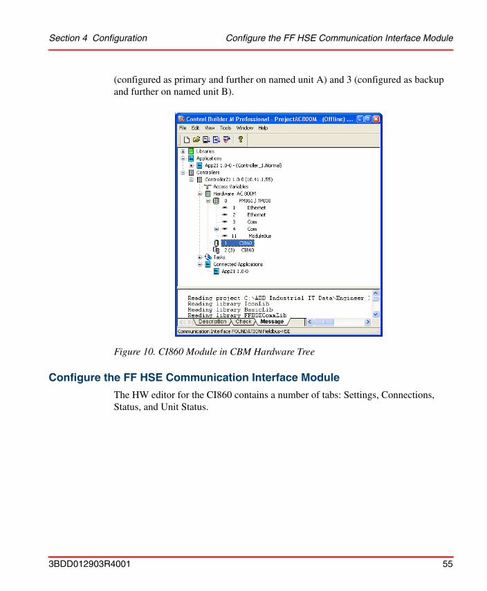
Section 4 Configuration Configure the FF HSE Communication Interface Module
(configured as primary and further on named unit A) and 3 (configured as backup and further on named unit B).
Configure the FF HSE Communication Interface Module
The HW editor for the CI860 contains a number of tabs: Settings, Connections, Status, and Unit Status.
Figure 10. CI860 Module in CBM Hardware Tree
3BDD012903R4001 55
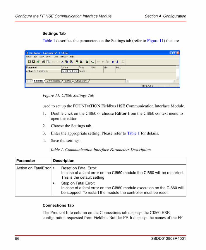
Configure the FF HSE Communication Interface Module Section 4 Configuration
Settings Tab
Table 1 describes the parameters on the Settings tab (refer to Figure 11) that are
used to set up the FOUNDATION Fieldbus HSE Communication Interface Module.
1. Double click on the CI860 or choose Editor from the CI860 context menu to open the editor.
2. Choose the Settings tab.
3. Enter the appropriate setting. Please refer to Table 1 for details.
4. Save the settings.
Connections Tab
The Protocol Info column on the Connections tab displays the CI860 HSE configuration requested from Fieldbus Builder FF. It displays the names of the FF
Figure 11. CI860 Settings Tab
Table 1. Communication Interface Parameters Description
Parameter Description
Action on FatalError • Reset on Fatal Error:In case of a fatal error on the CI860 module the CI860 will be restarted.This is the default setting
• Stop on Fatal Error:In case of a fatal error on the CI860 module execution on the CI860 will be stopped. To restart the module the controller must be reset.
56 3BDD012903R4001
Section 4 Configuration HSE Subnet Configuration
signals being mapped to CI860 channels. For further information on the Connections tab please refer to Connections Editor on page 73 and to Control Builder M online help.
Status and Unit Status Tabs
For information on the Status and Unit Status tabs please refer to Control Builder M online help and to Online Data on page 95.
HSE Subnet ConfigurationThe HSE subnet configuration is carried out in the Fieldbus Builder FF. If no HSE subnet has been configured at this point please refer to the Fieldbus Builder FF documentation ’800xA - Fieldbus, FOUNDATION Fieldbus Configuration’ for detailed information on how to create and configure an HSE subnet.
All objects belonging to an HSE subnet have an additional aspect: The FF Management aspect. Please refer to Figure 13. This aspect allows navigation to the corresponding object in Fieldbus Builder FF.
The HSE subnet object has another additional aspect: The FFUpload aspect. Please refer to Figure 12. Due to the information stored in this aspect the Control Builder M gets necessary configuration data for the CI860 from the Fieldbus Builder FF.
To start Fieldbus Builder FF do one of the following:
Start Fieldbus Builder FF from the FFUpload aspect
1. Navigate to the HSE subnet object in the Plant Explorer Control Structure.
3BDD012903R4001 57
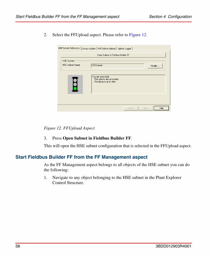
Start Fieldbus Builder FF from the FF Management aspect Section 4 Configuration
2. Select the FFUpload aspect. Please refer to Figure 12.
3. Press Open Subnet in Fieldbus Builder FF.
This will open the HSE subnet configuration that is selected in the FFUpload aspect.
Start Fieldbus Builder FF from the FF Management aspect
As the FF Management aspect belongs to all objects of the HSE subnet you can do the following:
1. Navigate to any object belonging to the HSE subnet in the Plant Explorer Control Structure.
Figure 12. FFUpload Aspect
58 3BDD012903R4001
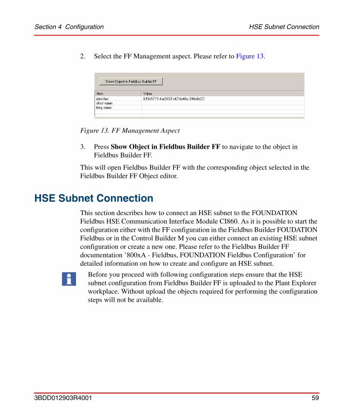
Section 4 Configuration HSE Subnet Connection
2. Select the FF Management aspect. Please refer to Figure 13.
3. Press Show Object in Fieldbus Builder FF to navigate to the object in Fieldbus Builder FF.
This will open Fieldbus Builder FF with the corresponding object selected in the Fieldbus Builder FF Object editor.
HSE Subnet ConnectionThis section describes how to connect an HSE subnet to the FOUNDATION Fieldbus HSE Communication Interface Module CI860. As it is possible to start the configuration either with the FF configuration in the Fieldbus Builder FOUDATION Fieldbus or in the Control Builder M you can either connect an existing HSE subnet configuration or create a new one. Please refer to the Fieldbus Builder FF documentation ’800xA - Fieldbus, FOUNDATION Fieldbus Configuration’ for detailed information on how to create and configure an HSE subnet.
Figure 13. FF Management Aspect
Before you proceed with following configuration steps ensure that the HSE subnet configuration from Fieldbus Builder FF is uploaded to the Plant Explorer workplace. Without upload the objects required for performing the configuration steps will not be available.
3BDD012903R4001 59
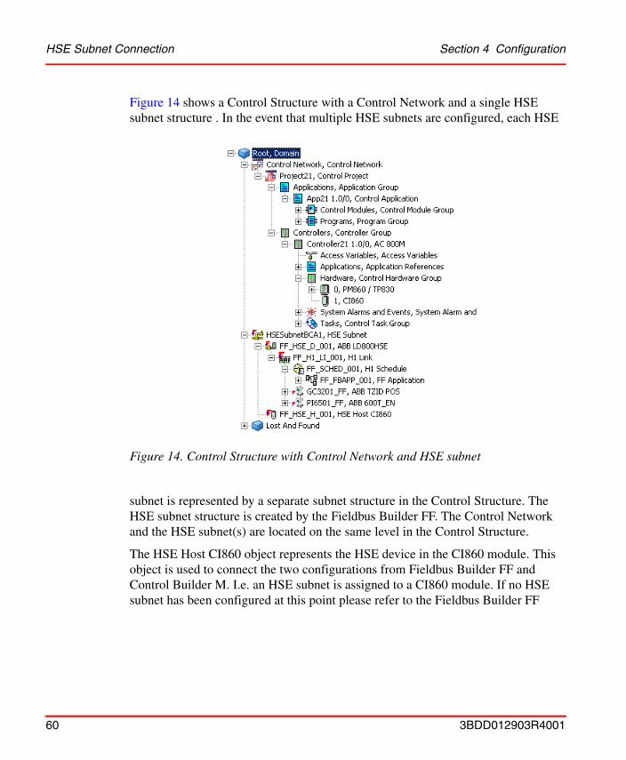
HSE Subnet Connection Section 4 Configuration
Figure 14 shows a Control Structure with a Control Network and a single HSE subnet structure . In the event that multiple HSE subnets are configured, each HSE
subnet is represented by a separate subnet structure in the Control Structure. The HSE subnet structure is created by the Fieldbus Builder FF. The Control Network and the HSE subnet(s) are located on the same level in the Control Structure.
The HSE Host CI860 object represents the HSE device in the CI860 module. This object is used to connect the two configurations from Fieldbus Builder FF and Control Builder M. I.e. an HSE subnet is assigned to a CI860 module. If no HSE subnet has been configured at this point please refer to the Fieldbus Builder FF
Figure 14. Control Structure with Control Network and HSE subnet
60 3BDD012903R4001
Section 4 Configuration HSE Subnet Connection
documentation ’800xA - Fieldbus, FOUNDATION Fieldbus Configuration’ for detailed information on how to create and configure an HSE subnet.
To establish the connection to the CI860 it is necessary to place a reference of the HSE Host CI860 object below the CI860 module in the Plant Explorer Control Structure. This object will not be visible in Control Builder M. To create a reference do the following:
1. Navigate to the HSE Host CI860 object in the Control Structure.
2. Select the HSE Host CI860 object.
3. Move the object while holding the CTRL+SHIFT keys to the CI860 object in your control project.
4. Drop the HSE Host CI860 object onto the CI860 object. Please refer to Figure 15.
5. Repeat steps 1 to 4 for all HSE Host CI860 objects in all HSE subnets.
You can download and go online with your project in Control Builder M without connecting an HSE Host CI860 object to a CI860 module. In this even a warning message is generated, but the the download is performed. The CI860 will still use the IP address and subnet mask, which have been configured the last time, but it will not publish any information to the HSE subnet.
The CI860 has by default the following network settings until reconfiguration:• IP Addresse: 172.16.32.48• Subnet Mask: 255.255.252.0• Default Gateway: 172.16.32.1
Only one HSE Host CI860 object can be placed below each CI860 object.
It is important to place a reference of the HSE Host CI860 object and no copy below the CI860 in order to establish the connection. To check that a reference is created verify that the HSE Host CI860 object has two Control Structure aspects, not only one (this would indicate that a copy has been created).
3BDD012903R4001 61

HSE Subnet Connection Section 4 Configuration
Alternatively do the following:
1. Navigate to the CI860 object in your Control Project.
2. Select Insert object from the context menu.
Figure 15. Create Reference of the HSE Host CI860 Object.
62 3BDD012903R4001
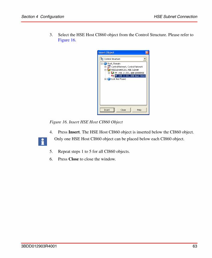
Section 4 Configuration HSE Subnet Connection
3. Select the HSE Host CI860 object from the Control Structure. Please refer to Figure 16.
4. Press Insert. The HSE Host CI860 object is inserted below the CI860 object.
5. Repeat steps 1 to 5 for all CI860 objects.
6. Press Close to close the window.
Figure 16. Insert HSE Host CI860 Object
Only one HSE Host CI860 object can be placed below each CI860 object.
3BDD012903R4001 63

HSE Subnet Connection Section 4 Configuration
Now a reference of the HSE Host CI860 object has been inserted below the CI860 object. Please refer to Figure 17. Selecting the HSE Host CI860 object shows that it
now has two Control Structure aspects as it is placed twice in the Control Structure. Both HSE Host CI860 objects are a representation of the same data: changing one also changes the other.
In the event that multiple HSE subnets need to be connected repeat the procedure for each HSE subnet. Connect each HSE subnet to the CI860 module(s) with which you want to communicate or process FF data.
The FFUpload aspect contains the information which HSE subnet configuration from disk is loaded to the HSE subnet in the Plant Explorer Control Structure.
Figure 17. Reference to HSE Host CI860 Object added below CI860 Object
64 3BDD012903R4001

Section 4 Configuration LD 800HSE Linking Device Configuration
This together with the HSE Host CI860 object that is inserted under the CI860 object determines the CI860 configuration that is supplied to Control Builder M.
LD 800HSE Linking Device ConfigurationThe Linking Device configuration is carried out in the Fieldbus Builder FF. For IP address and subnet mask configuration please refer to the Fieldbus Builder FF documentation ’800xA - Fieldbus, FOUNDATION Fieldbus Configuration’ and to Setting the IP Address and Subnet Mask for the Linking Device on page 52. To enter Fieldbus Builder FF configuration please refer to HSE Subnet Configuration on page 57.
FOUNDATION Fieldbus H1 Device ConfigurationThe configuration for H1 links is carried out in the Fieldbus Builder FF. Please refer to the Fieldbus Builder FF documentation ’800xA - Fieldbus, FOUNDATION Fieldbus Configuration’. To enter Fieldbus Builder FF configuration please refer to HSE Subnet Configuration on page 57.
Configuration Changes
FF HSE Subnet Configuration Changes
All changes to the configuration of the HSE subnet and H1 links must be carried out in the Fieldbus Builder FF. Please refer to the Fieldbus Builder FF documentation ’800xA - Fieldbus, FOUNDATION Fieldbus Configuration’. To enter Fieldbus Builder FF configuration please refer to HSE Subnet Configuration on page 57.
Please ensure that the configured structure meets the FF HSE subnet structure in the field. I.e make sure that you haven chosen the correct CI860 and the correct subnet to connect so that the connection between HSE subnet and CI860 module(s) is setup properly.
3BDD012903R4001 65
CI860 Configuration Changes Section 4 Configuration
CI860 Configuration Changes
Control Builder M gets the CI860 configuration i.e. the CI860 HSE configuration and the IP address(es) from Fieldbus Builder FF. Thereby those FF signals are defined that will be communicated with the CI860.
The Control Builder M fetches the CI860 HSE configuration either from the last saved Fieldbus Builder FF configuration or from a Fieldbus Builder configuration that is currently open in Fieldbus Builder FF. In both cases Control Builder M gets the CI860 HSE configuration provided that the CI860 HSE Host object in Fieldbus Builder FF is plausible/checked. The CI860 Protocol Info column is updated once the CI860 hardware editor is opened in Control Builder M. If the hardware editor is already open, close the editor and open it again.
FF HSE Subnet Connection Changes
Changing the connection between an HSE subnet and a CI860 module requires special attention as the IP address of the CI860 module is part of the HSE subnet configuration and therefore set in Fieldbus Builder FF.
To connect an HSE subnet to another CI860 module in the same or a different AC 800M controller you simply have to move the HSE Host CI860 object to another CI860 module in the plant Explorer Workplace Control Structure. Therefore the CI860 module to which the HSE Host CI860 object is connected now gets the configuration from that HSE subnet. Thereby this CI860 module gets the same IP address assigned as the previous CI860 module if this is not provided with a new HSE subnet connection containing a different IP address.
This will cause an address conflict on the HSE subnet after the controller(s) have been loaded, reset, so that the IP address change on the CI860 becomes effective and loaded again. A CI860 module that has no connection to an HSE subnet will be loaded from Control Builder M with a null configuration. I.e. no CI860 HSE
If the CI860 HSE Host object is not plausible/checked in Fieldbus Builder FF or no HSE Host CI860 object is connect to the CI860 the hardware editor will show <NOT FOUND> in Protocol Info column. If the CI860 HSE Host object is not plausible/checked in Fieldbus Builder FF you cannot download and go online.
66 3BDD012903R4001
Section 4 Configuration FF HSE Subnet Connection Changes
configuration is provided and no IP address. Therefore the CI860 module will keep the previous IP address that is now also use by the second CI860 module.
To avoid IP address conflicts on the HSE subnets ensure that each CI860 module in the plant Explorer Workplace Control Structure is connected to an HSE subnet containing a unique IP address for this CI860 module.
3BDD012903R4001 67
FF HSE Subnet Connection Changes Section 4 Configuration
68 3BDD012903R4001

Section 5 Application Programming
IntroductionThis section describes how to read and write FOUNDATION Fieldbus signals and how to use them in Control Builder M applications. There are two different methods of accessing data from FOUNDATION Fieldbus. FF signals can be mapped to variables so they can be used in any program or control module. See FF Signal Mapping on page 72. Apart from this, a number of FOUNDATION Fieldbus specific objects are available: Two specific control modules to access analog signals, see Analog Handling on page 80, and four function blocks for digital signal handling, see Digital Handling on page 86.
Distributed Control with FOUNDATION Fieldbus
FOUNDATION Fieldbus enables control applications to be run on the FOUNDATION Fieldbus field devices. Hence the applications can be run distributed on the field devices. This feature is unique to FOUNDATION Fieldbus. The applications (i.e. control loops) must be configured with the Fieldbus Builder FOUNDATION Fieldbus. After downloading, the applications are run on FF H1 devices. Selected signals can be written to and read from the CI860. Fieldbus Builder FF is used to configure the signals communicated with the CI860. Using Control Builder M, signals communicated with the CI860 can be mapped to IEC 61131 variables. Thereby FF signals are available for Control Builder M applications.
Using FOUNDATION Fieldbus as I/O Bus
Although FOUNDATION Fieldbus allows for distributed control it is possible to use FOUNDATION Fieldbus as an I/O bus. Anyhow an application must be created with the Fieldbus Builder FF. Hence the necessary configuration steps are similar to a configuration using distributed control. Fieldbus Builder FF is used to configure
3BDD012903R4001 69
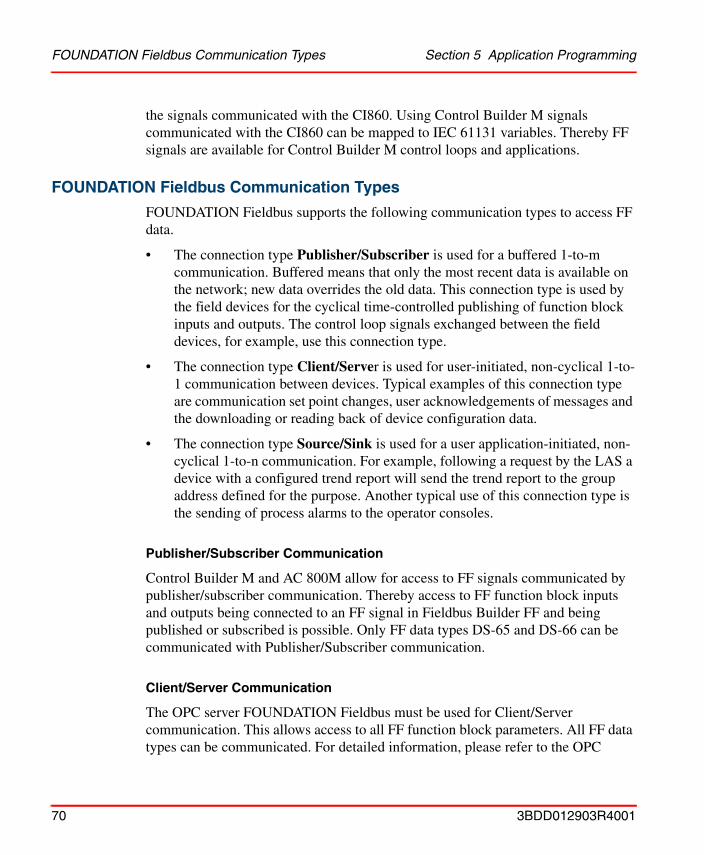
FOUNDATION Fieldbus Communication Types Section 5 Application Programming
the signals communicated with the CI860. Using Control Builder M signals communicated with the CI860 can be mapped to IEC 61131 variables. Thereby FF signals are available for Control Builder M control loops and applications.
FOUNDATION Fieldbus Communication Types
FOUNDATION Fieldbus supports the following communication types to access FF data.
• The connection type Publisher/Subscriber is used for a buffered 1-to-m communication. Buffered means that only the most recent data is available on the network; new data overrides the old data. This connection type is used by the field devices for the cyclical time-controlled publishing of function block inputs and outputs. The control loop signals exchanged between the field devices, for example, use this connection type.
• The connection type Client/Server is used for user-initiated, non-cyclical 1-to-1 communication between devices. Typical examples of this connection type are communication set point changes, user acknowledgements of messages and the downloading or reading back of device configuration data.
• The connection type Source/Sink is used for a user application-initiated, non-cyclical 1-to-n communication. For example, following a request by the LAS a device with a configured trend report will send the trend report to the group address defined for the purpose. Another typical use of this connection type is the sending of process alarms to the operator consoles.
Publisher/Subscriber Communication
Control Builder M and AC 800M allow for access to FF signals communicated by publisher/subscriber communication. Thereby access to FF function block inputs and outputs being connected to an FF signal in Fieldbus Builder FF and being published or subscribed is possible. Only FF data types DS-65 and DS-66 can be communicated with Publisher/Subscriber communication.
Client/Server Communication
The OPC server FOUNDATION Fieldbus must be used for Client/Server communication. This allows access to all FF function block parameters. All FF data types can be communicated. For detailed information, please refer to the OPC
70 3BDD012903R4001

Section 5 Application Programming FOUNDATION Fieldbus Application Configuration
Server FF documentation ’800xA - Fieldbus, FOUNDATION Fieldbus Configuration’.
Source/Sink Communication
This communication type is not supported in this version.
FOUNDATION Fieldbus Application ConfigurationFOUNDATION Fieldbus applications running on the FOUNDATION Fieldbus field devices must be configured with the Fieldbus Builder FF. Please refer to the Fieldbus Builder FF documentation ’800xA - Fieldbus, FOUNDATION Fieldbus Configuration’ for detailed information.
Control Builder M Application Programming This section describes how to use FF signals in Control Builder M applications. For information on application programming that is not specific to FOUNDATION Fieldbus please refer to the Control Builder M documentation. The following sections contain information on how to use FF signals in Control Builder M applications.
Data Types
The analog FF data type DS-65 is mapped to the RealIO data type. The discrete FF data type DS-66 can contain binary information but also up to 256 states (one byte). For these different usages two AC 800M data types can be mapped to the discrete FF signal: The BoolIO for binary usage and the DwordIO for the full usage of all possible values. The CI860 provides these two possibilities for a discrete channel.
For discrete outputs only one of these two data types can be used for the same channel at the same time, but different channels in the discrete section can be used with the different IO data types BoolIO and DwordIO. For discrete inputs this restriction does not apply.
3BDD012903R4001 71
FF Signal Status Handling Section 5 Application Programming
FF Signal Status Handling
FF signals contain value and status information. The status value can be split into status values and sub-status. There are four (4) major status values each having a set of up to 16 possible sub-status values.
The following values exist for the major status:• Good (Cascade) - the value may be used in control.• Uncertain - the quality of the value is less than normal, but it may still prove
useful.• Good (Non-cascade) - the quality of the value is good, but possible alarm
conditions may be indicated in the sub-status.• Bad – the value is not useful.
Refer to FOUNDATION Fieldbus FB Part 1 Specification (FF890) for additional details about valid sub-status values.
For proper handling of FF signals it is necessary to handle the FF status information in Control Builder M applications. This especially applies to an instance which IEC 61131 variables are to be written to FF signals. Dedicated FF control modules and function blocks offer convenient handling of this status information. See FF Status Handling on page 36 and FF Specific Control Modules and Function Blocks on page 77.
FF Signal Mapping
This section describes how to map FF signals to variables, i.e. how to access FF data from your Control Builder M application. Select the CI860 module and open the editor. Choose the Connections tab to enter the connections editor.
72 3BDD012903R4001
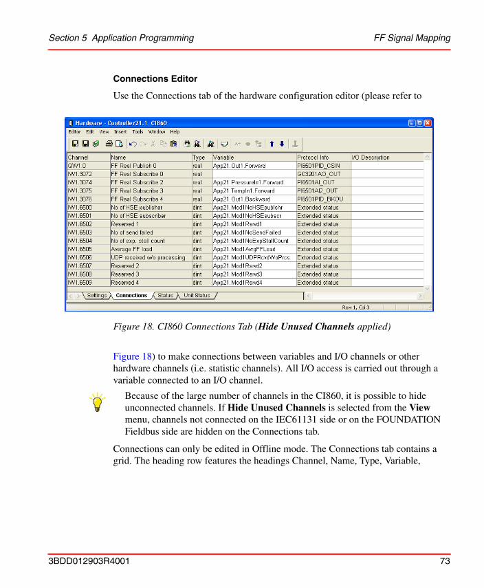
Section 5 Application Programming FF Signal Mapping
Connections Editor
Use the Connections tab of the hardware configuration editor (please refer to
Figure 18) to make connections between variables and I/O channels or other hardware channels (i.e. statistic channels). All I/O access is carried out through a variable connected to an I/O channel.
Connections can only be edited in Offline mode. The Connections tab contains a grid. The heading row features the headings Channel, Name, Type, Variable,
Figure 18. CI860 Connections Tab (Hide Unused Channels applied)
Because of the large number of channels in the CI860, it is possible to hide unconnected channels. If Hide Unused Channels is selected from the View menu, channels not connected on the IEC61131 side or on the FOUNDATION Fieldbus side are hidden on the Connections tab.
3BDD012903R4001 73
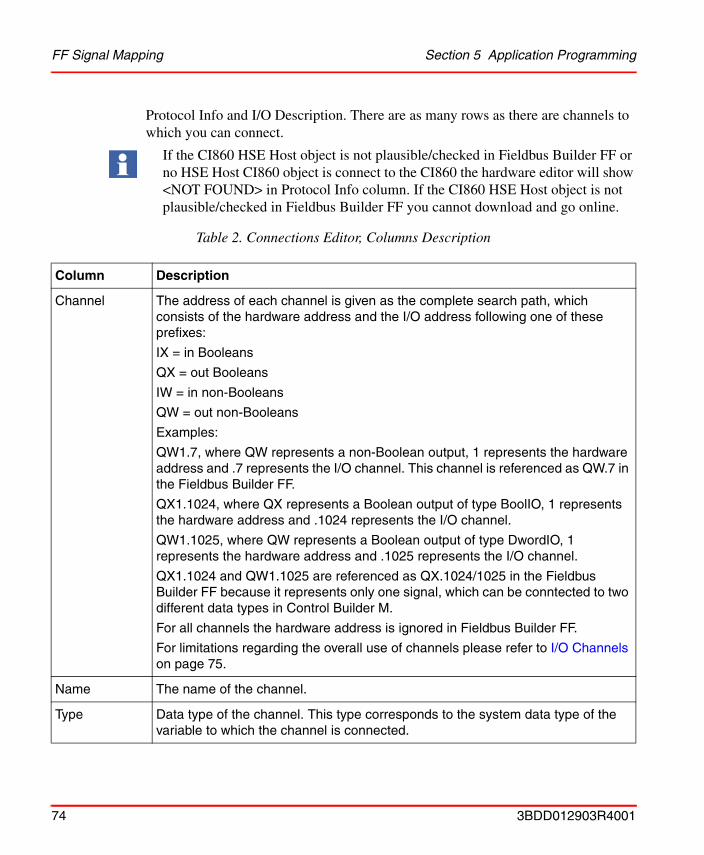
FF Signal Mapping Section 5 Application Programming
Protocol Info and I/O Description. There are as many rows as there are channels to which you can connect.
If the CI860 HSE Host object is not plausible/checked in Fieldbus Builder FF or no HSE Host CI860 object is connect to the CI860 the hardware editor will show <NOT FOUND> in Protocol Info column. If the CI860 HSE Host object is not plausible/checked in Fieldbus Builder FF you cannot download and go online.
Table 2. Connections Editor, Columns Description
Column Description
Channel The address of each channel is given as the complete search path, which consists of the hardware address and the I/O address following one of these prefixes:
IX = in Booleans
QX = out Booleans
IW = in non-Booleans
QW = out non-Booleans
Examples:
QW1.7, where QW represents a non-Boolean output, 1 represents the hardware address and .7 represents the I/O channel. This channel is referenced as QW.7 in the Fieldbus Builder FF.
QX1.1024, where QX represents a Boolean output of type BoolIO, 1 represents the hardware address and .1024 represents the I/O channel.
QW1.1025, where QW represents a Boolean output of type DwordIO, 1 represents the hardware address and .1025 represents the I/O channel.
QX1.1024 and QW1.1025 are referenced as QX.1024/1025 in the Fieldbus Builder FF because it represents only one signal, which can be conntected to two different data types in Control Builder M.
For all channels the hardware address is ignored in Fieldbus Builder FF.
For limitations regarding the overall use of channels please refer to I/O Channels on page 75.
Name The name of the channel.
Type Data type of the channel. This type corresponds to the system data type of the variable to which the channel is connected.
74 3BDD012903R4001
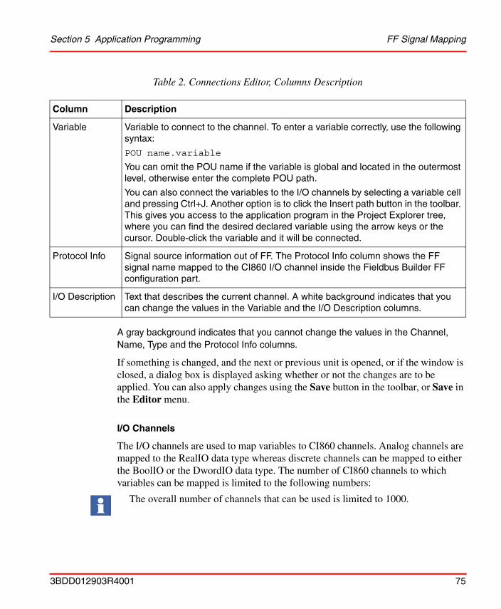
Section 5 Application Programming FF Signal Mapping
A gray background indicates that you cannot change the values in the Channel, Name, Type and the Protocol Info columns.
If something is changed, and the next or previous unit is opened, or if the window is closed, a dialog box is displayed asking whether or not the changes are to be applied. You can also apply changes using the Save button in the toolbar, or Save in the Editor menu.
I/O Channels
The I/O channels are used to map variables to CI860 channels. Analog channels are mapped to the RealIO data type whereas discrete channels can be mapped to either the BoolIO or the DwordIO data type. The number of CI860 channels to which variables can be mapped is limited to the following numbers:
Variable Variable to connect to the channel. To enter a variable correctly, use the following syntax:
POU name.variable
You can omit the POU name if the variable is global and located in the outermost level, otherwise enter the complete POU path.
You can also connect the variables to the I/O channels by selecting a variable cell and pressing Ctrl+J. Another option is to click the Insert path button in the toolbar. This gives you access to the application program in the Project Explorer tree, where you can find the desired declared variable using the arrow keys or the cursor. Double-click the variable and it will be connected.
Protocol Info Signal source information out of FF. The Protocol Info column shows the FF signal name mapped to the CI860 I/O channel inside the Fieldbus Builder FF configuration part.
I/O Description Text that describes the current channel. A white background indicates that you can change the values in the Variable and the I/O Description columns.
The overall number of channels that can be used is limited to 1000.
Table 2. Connections Editor, Columns Description
Column Description
3BDD012903R4001 75
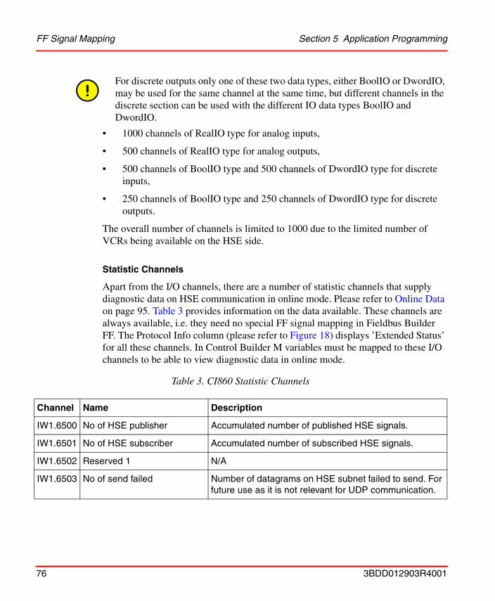
FF Signal Mapping Section 5 Application Programming
• 1000 channels of RealIO type for analog inputs,
• 500 channels of RealIO type for analog outputs,
• 500 channels of BoolIO type and 500 channels of DwordIO type for discrete inputs,
• 250 channels of BoolIO type and 250 channels of DwordIO type for discrete outputs.
The overall number of channels is limited to 1000 due to the limited number of VCRs being available on the HSE side.
Statistic Channels
Apart from the I/O channels, there are a number of statistic channels that supply diagnostic data on HSE communication in online mode. Please refer to Online Data on page 95. Table 3 provides information on the data available. These channels are always available, i.e. they need no special FF signal mapping in Fieldbus Builder FF. The Protocol Info column (please refer to Figure 18) displays ’Extended Status’ for all these channels. In Control Builder M variables must be mapped to these I/O channels to be able to view diagnostic data in online mode.
For discrete outputs only one of these two data types, either BoolIO or DwordIO, may be used for the same channel at the same time, but different channels in the discrete section can be used with the different IO data types BoolIO and DwordIO.
Table 3. CI860 Statistic Channels
Channel Name Description
IW1.6500 No of HSE publisher Accumulated number of published HSE signals.
IW1.6501 No of HSE subscriber Accumulated number of subscribed HSE signals.
IW1.6502 Reserved 1 N/A
IW1.6503 No of send failed Number of datagrams on HSE subnet failed to send. For future use as it is not relevant for UDP communication.
76 3BDD012903R4001
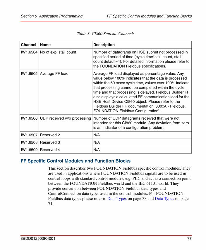
Section 5 Application Programming FF Specific Control Modules and Function Blocks
FF Specific Control Modules and Function Blocks
This section describes two FOUNDATION Fieldbus specific control modules. They are used in applications where FOUNDATION Fieldbus signals are to be used in control loops with standard control modules, e.g. PID, and act as a connection point between the FOUNDATION Fieldbus world and the IEC 61131 world. They provide conversion between FOUNDATION Fieldbus data types and ControlConnection data type, used in the control modules. For FOUNDATION Fieldbus data types please refer to Data Types on page 33 and Data Types on page 71.
IW1.6504 No of exp. stall count Number of datagrams on HSE subnet not processed in specified period of time (cycle time*stall count, stall count default=4). For detailed information please refer to the FOUNDATION Fieldbus specifications.
IW1.6505 Average FF load Average FF load displayed as percentage value. Any value below 100% indicates that the data is processed within the 50 msec cycle time, values over 100% indicate that processing cannot be completed within the cycle time and that processing is delayed. Fieldbus Builder FF also displays a calculated FF communication load for the HSE Host Device CI860 object. Please refer to the Fieldbus Builder FF documentation ’800xA - Fieldbus, FOUNDATION Fieldbus Configuration’.
IW1.6506 UDP received w/o processing Number of UDP datagrams received that were not intended for this CI860 module. Any deviation from zero is an indicator of a configuration problem.
IW1.6507 Reserved 2 N/A
IW1.6508 Reserved 3 N/A
IW1.6509 Reserved 4 N/A
Table 3. CI860 Statistic Channels
Channel Name Description
3BDD012903R4001 77
FF Specific Control Modules and Function Blocks Section 5 Application Programming
The section also describes four FOUNDATION Fieldbus specific function blocks for digital signals which handle conversion between FOUNDATION Fieldbus signals and IEC 61131 signals.
FF HSE Communication Library
The control modules and function blocks described in the following sections are contained in the FFHSECommLib. Please refer to Table 4 and Table 5. This library needs to be added to your Control Builder M project. Once the library has been added to your project you can connect it to those applications in which you want to use the control modules and function blocks contained in the library. To add the FFHSECommLib to your project do the following:
1. Select your control project in the Plant Explorer workplace.
2. Select the Project aspect.
3. Switch to the Libraries tab.
4. Press Insert to add a library.
78 3BDD012903R4001
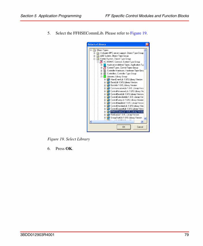
Section 5 Application Programming FF Specific Control Modules and Function Blocks
5. Select the FFHSECommLib. Please refer to Figure 19.
6. Press OK.
Figure 19. Select Library
3BDD012903R4001 79
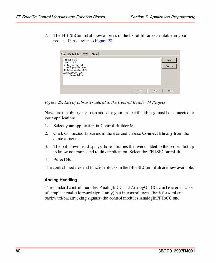
FF Specific Control Modules and Function Blocks Section 5 Application Programming
7. The FFHSECommLib now appears in the list of libraries available in your project. Please refer to Figure 20.
Now that the library has been added to your project the library must be connected to your applications.
1. Select your application in Control Builder M.
2. Click Connected Libraries in the tree and choose Connect library from the context menu.
3. The pull down list displays those libraries that were added to the project but up to know not connected to this application. Select the FFHSECommLib.
4. Press OK.
The control modules and function blocks in the FFHSECommLib are now available.
Analog Handling
The standard control modules, AnalogInCC and AnalogOutCC, can be used in cases of simple signals (forward signal only) but in control loops (both forward and backward/backtracking signals) the control modules AnalogInFFToCC and
Figure 20. List of Libraries added to the Control Builder M Project
80 3BDD012903R4001
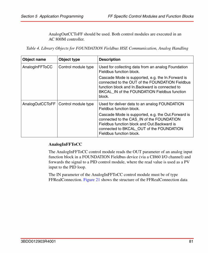
Section 5 Application Programming FF Specific Control Modules and Function Blocks
AnalogOutCCToFF should be used. Both control modules are executed in an AC 800M controller.
AnalogInFFToCC
The AnalogInFFToCC control module reads the OUT parameter of an analog input function block in a FOUNDATION Fieldbus device (via a CI860 I/O channel) and forwards the signal to a PID control module, where the read value is used as a PV input to the PID loop.
The IN parameter of the AnalogInFFToCC control module must be of type FFRealConnection. Figure 21 shows the structure of the FFRealConnection data
Table 4. Library Objects for FOUNDATION Fieldbus HSE Communication, Analog Handling
Object name Object type Description
AnalogInFFToCC Control module type Used for collecting data from an analog Foundation Fieldbus function block.
Cascade Mode is supported, e.g. the In.Forward is connected to the OUT of the FOUNDATION Fieldbus function block and In.Backward is connected to BKCAL_IN of the FOUNDATION Fieldbus function block.
AnalogOutCCToFF Control module type Used for deliver data to an analog FOUNDATION Fieldbus function block.
Cascade Mode is supported, e.g. the Out.Forward is connected to the CAS_IN of the FOUNDATION Fieldbus function block and Out.Backward is connected to BKCAL_OUT of the FOUNDATION Fieldbus function block.
3BDD012903R4001 81
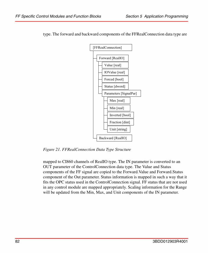
FF Specific Control Modules and Function Blocks Section 5 Application Programming
type. The forward and backward components of the FFRealConnection data type are
mapped to CI860 channels of RealIO type. The IN parameter is converted to an OUT parameter of the ControlConnection data type. The Value and Status components of the FF signal are copied to the Forward.Value and Forward.Status component of the Out parameter. Status information is mapped in such a way that it fits the OPC status used in the ControlConnection signal. FF status that are not used in any control module are mapped appropriately. Scaling information for the Range will be updated from the Min, Max, and Unit components of the IN parameter.
Figure 21. FFRealConnection Data Type Structure
[FFRealConnection]
Forward [RealIO]
Value [real]
IOValue [real]
Forced [bool]
Parameters [SignalPar]
Max [real]
Status [dword]
Min [real]
Inverted [bool]
Fraction [dint]
Unit [string]
Backward [RealIO]
82 3BDD012903R4001

Section 5 Application Programming FF Specific Control Modules and Function Blocks
The OUT parameter can be graphically connected - all other parameters are connected in the connections editor. Please refer to Figure 22.
AnalogOutCCToFF
The AnalogOutCCToFF control module writes the Value and Status components of the IN parameter, which in the example below is a copy of the OUT parameter of a PID master in the controller. The data is transferred to a PID slave function block in a FOUNDATION Fieldbus device (working as a cascade loop, PID.Cas_IN
Figure 22. AnalogInFFToCC Connections Editor
3BDD012903R4001 83
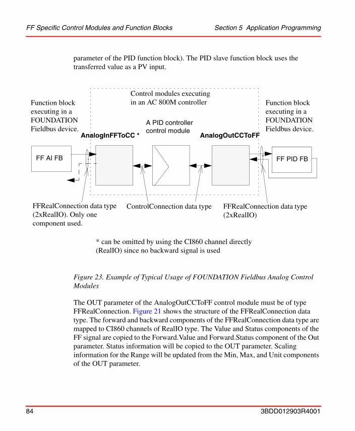
FF Specific Control Modules and Function Blocks Section 5 Application Programming
parameter of the PID function block). The PID slave function block uses the transferred value as a PV input.
The OUT parameter of the AnalogOutCCToFF control module must be of type FFRealConnection. Figure 21 shows the structure of the FFRealConnection data type. The forward and backward components of the FFRealConnection data type are mapped to CI860 channels of RealIO type. The Value and Status components of the FF signal are copied to the Forward.Value and Forward.Status component of the Out parameter. Status information will be copied to the OUT parameter. Scaling information for the Range will be updated from the Min, Max, and Unit components of the OUT parameter.
Figure 23. Example of Typical Usage of FOUNDATION Fieldbus Analog Control Modules
ControlConnection data type FFRealConnection data type(2xRealIO)
FFRealConnection data type(2xRealIO). Only one component used.
AnalogOutCCToFFAnalogInFFToCC *
FF AI FB FF PID FB
A PID controller control module
Control modules executing in an AC 800M controllerFunction block
executing in a FOUNDATION Fieldbus device.
Function block executing in a FOUNDATION Fieldbus device.
* can be omitted by using the CI860 channel directly (RealIO) since no backward signal is used
84 3BDD012903R4001
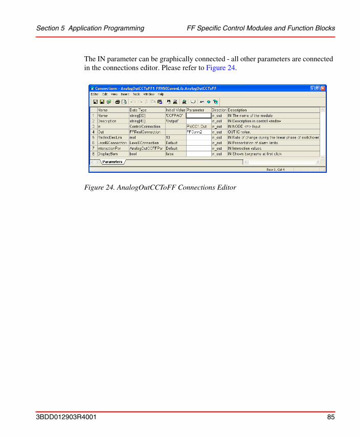
Section 5 Application Programming FF Specific Control Modules and Function Blocks
The IN parameter can be graphically connected - all other parameters are connected in the connections editor. Please refer to Figure 24.
Figure 24. AnalogOutCCToFF Connections Editor
3BDD012903R4001 85

FF Specific Control Modules and Function Blocks Section 5 Application Programming
Digital Handling
There are four FOUNDATION Fieldbus specific function blocks for digital signals which handle conversion between FF signals and IEC 61131 signals. The function blocks are used with a user written application.
Table 5. Library Objects for FOUNDATION Fieldbus HSE Communication, Digital Handling
Name Object type Description
FFToBoolIOIn Function block type Used for collecting data from a discrete FOUNDATION Fieldbus function block.
The FOUNDATION Fieldbus boolean structure (DS66) is mapped to a bool, false(0) or true(1).
BoolIOToFFOut Function block type Used to deliver data to a discrete FOUNDATION Fieldbus function block.
The FOUNDATION Fieldbus boolean structure (DS66) is mapped to a bool, false(0) or true(1).
Cascade Mode is supported, e.g. the Out.Forward is connected to the DCAS_IN of the FOUNDATION Fieldbus function block and Out.Backward is connected to DBKCAL_OUT of the FOUNDATION Fieldbus function block.
86 3BDD012903R4001
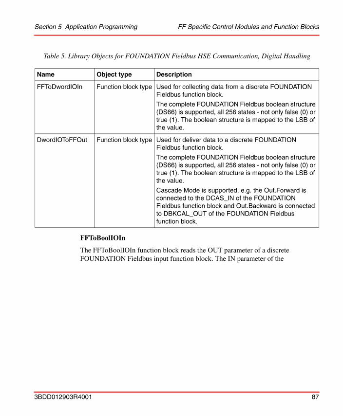
Section 5 Application Programming FF Specific Control Modules and Function Blocks
FFToBoolIOIn
The FFToBoolIOIn function block reads the OUT parameter of a discrete FOUNDATION Fieldbus input function block. The IN parameter of the
FFToDwordIOIn Function block type Used for collecting data from a discrete FOUNDATION Fieldbus function block.
The complete FOUNDATION Fieldbus boolean structure (DS66) is supported, all 256 states - not only false (0) or true (1). The boolean structure is mapped to the LSB of the value.
DwordIOToFFOut Function block type Used for deliver data to a discrete FOUNDATION Fieldbus function block.
The complete FOUNDATION Fieldbus boolean structure (DS66) is supported, all 256 states - not only false (0) or true (1). The boolean structure is mapped to the LSB of the value.
Cascade Mode is supported, e.g. the Out.Forward is connected to the DCAS_IN of the FOUNDATION Fieldbus function block and Out.Backward is connected to DBKCAL_OUT of the FOUNDATION Fieldbus function block.
Table 5. Library Objects for FOUNDATION Fieldbus HSE Communication, Digital Handling
Name Object type Description
3BDD012903R4001 87

FF Specific Control Modules and Function Blocks Section 5 Application Programming
FFToBoolIOIn function block must be of type FFBoolConnection. Figure 25 shows
the structure of the FFBoolConnection data type. The forward component of the FFBoolConnection data type is mapped to a CI860 channel of BoolIO type. The Value and Status components of the FF signal are copied to the Value and Status components of the Out parameter of type BoolIO.
BoolIOToFFOut
The BoolIOToFFOut function block writes to the IN parameter of a discrete FOUNDATION Fieldbus output function block. The OUT parameter of the BoolIOToFFOut function block must be of type FFBoolConnection. Figure 25 shows the structure of the FFBoolConnection data type. The forward and backward components of the FFBoolConnection data type are mapped to a CI860 channel of BoolIO type. The Value and Status components of the FF signal are copied from the Value and Status component of the IN parameter of type BoolIO.
Figure 25. FFBoolConnection Data Type Structure
Forward [BoolIO]
Value [bool]
IOValue [bool]
Forced [bool]
Status [dword]
Backward [BoolIO]
Value [bool]
IOValue [bool]
Forced [bool]
Status [dword]
[FFBoolConnection]
88 3BDD012903R4001
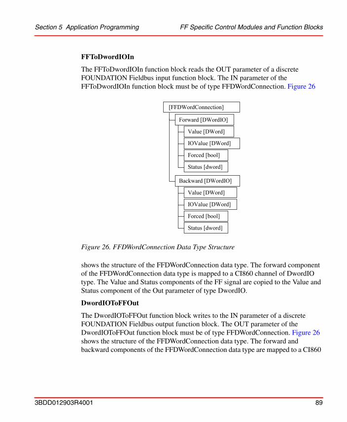
Section 5 Application Programming FF Specific Control Modules and Function Blocks
FFToDwordIOIn
The FFToDwordIOIn function block reads the OUT parameter of a discrete FOUNDATION Fieldbus input function block. The IN parameter of the FFToDwordIOIn function block must be of type FFDWordConnection. Figure 26
shows the structure of the FFDWordConnection data type. The forward component of the FFDWordConnection data type is mapped to a CI860 channel of DwordIO type. The Value and Status components of the FF signal are copied to the Value and Status component of the Out parameter of type DwordIO.
DwordIOToFFOut
The DwordIOToFFOut function block writes to the IN parameter of a discrete FOUNDATION Fieldbus output function block. The OUT parameter of the DwordIOToFFOut function block must be of type FFDWordConnection. Figure 26 shows the structure of the FFDWordConnection data type. The forward and backward components of the FFDWordConnection data type are mapped to a CI860
Figure 26. FFDWordConnection Data Type Structure
Forward [DWordIO]
Value [DWord]
IOValue [DWord]
Forced [bool]
Status [dword]
Backward [DWordIO]
Value [DWord]
IOValue [DWord]
Forced [bool]
Status [dword]
[FFDWordConnection]
3BDD012903R4001 89
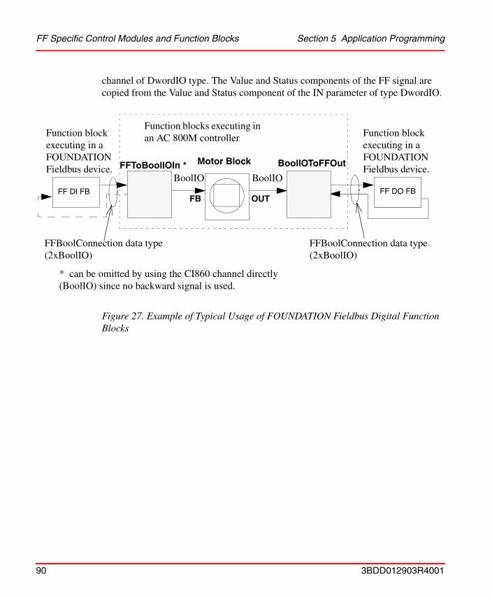
FF Specific Control Modules and Function Blocks Section 5 Application Programming
channel of DwordIO type. The Value and Status components of the FF signal are copied from the Value and Status component of the IN parameter of type DwordIO.
Figure 27. Example of Typical Usage of FOUNDATION Fieldbus Digital Function Blocks
BoolIOFF DO FB
FFBoolConnection data type(2xBoolIO)
BoollOToFFOutFFToBoolIOIn * Motor Block
BoolIO
Function blocks executing in an AC 800M controller
FBFF DI FB
* can be omitted by using the CI860 channel directly (BoolIO) since no backward signal is used.
OUT
Function block executing in a FOUNDATION Fieldbus device.
Function block executing in a FOUNDATION Fieldbus device.
FFBoolConnection data type(2xBoolIO)
90 3BDD012903R4001
Section 6 Download and Online Mode
This section describes how to download and go online with a project accessing FOUNDATION Fieldbus data.
Preconditions
FOUNDATION Fieldbus HSE Subnet Configuration
To be able to read and write FOUNDATION Fieldbus data first you have to download the Fieldbus Builder FOUNDATION Fieldbus configuration to the HSE subnet(s). Two cases must be considered.
• The Fieldbus Builder FF HSE subnet configuration contains no H1 devices with instantiatable function blocks.
• The Fieldbus Builder FF HSE subnet contains configuration H1 devices with instantiatable function blocks.
The following sections provide information for both cases on the steps required in Fieldbus Builder FF.
HSE Subnet Configuration with H1 Devices Containing No Instantiatable Function Blocks
This invokes the following steps in Fieldbus Builder FF:
1. Check
2. Prepare for commissioning of the FF Linking DeviceThe FF Linking Device is initialized and addresses are assigned.
If you have carried out this step, you may download the controller. Anyhow you will not get any FF live data until you have carried out the next steps.
3BDD012903R4001 91

Firmware Upgrade Section 6 Download and Online Mode
3. Assign H1 devicesFor each H1 link:Each device actually present on the H1 link is assigned to a configured device.
4. Load FF Linking Device and all H1 linksThe FF Linking Device and all devices on the H1 links are loaded along with their configuration data.
HSE Subnet Configuration with H1 Devices Containing Instantiatable Function Blocks
This invokes the following steps in Fieldbus Builder FF:
1. Check
2. Prepare for commissioning of the FF Linking DeviceThe FF Linking Device is initialized and addresses are assigned.
3. Assign H1 devicesFor each H1 link:Each device actually present on the H1 link is assigned to a configured device.
4. Check
5. Load FF Linking Device and all H1 linksThe FF Linking Device and all devices on the H1 links are loaded along with their configuration data.
Firmware Upgrade
Before you can download the AC 800M controller ensure that the processor module as well as the CI860 contain the correct firmware. Please refer to Control Builder M documentation and online help for further information.
If you have carried out this step, you may download the controller. Anyhow you will not get any FF live data until you have carried out the next step.
These steps are necessary to ensure that function blocks from devices with instantiatable function blocks receive correct indices assigned which are part of the CI860 configuration data.
92 3BDD012903R4001
Section 6 Download and Online Mode CI860 IP Address Change
CI860 IP Address Change
Downloading Now that the HSE subnet is downloaded and running and the firmware is up to date you can download the controller and go online and test your application.
If the IP address or subnet mask for a CI860 is changed and downloaded to the CI860, a reset on the CI860 will be performed automatically. The new settings will become effective after this reset.
If the IP address or subnet mask for a CI860 operating in redundant mode is changed the reset will be performed automatically as well. If the reset is performed for the CI860 currently working as primary module, a fail over to the backup module is performed.
If the reset is performed in the CI860 currently working as backup module, the primary module is not effected.
If the reset has to be performed on both modules, the module, which is configured in Control Builder M as the primary (module A, please refer to Figure 10 for details), will act as the primary module after reconfiguration. Because of the reconfiguration of primary and backup module the HSE communication is interrupted during the IP address or subnet mask changes.
The CI860 has by default the following network settings until reconfiguration:• IP Addresse: 172.16.32.48
• Subnet Mask: 255.255.252.0
• Default Gateway: 172.16.32.1
3BDD012903R4001 93
Configuration Changes Section 6 Download and Online Mode
Configuration Changes
Configuration changes in Fieldbus Builder FF and Control Builder M should be handled with care.
The Control Builder M fetches the CI860 HSE configuration (please refer to Connections Editor on page 73) either from the last saved Fieldbus Builder FF HSE subnet configuration or from a HSA subnet configuration that is currently open in Fieldbus Builder FF. In both cases Control Builder M gets the CI860 HSE configuration provided that the CI860 HSE Host object in Fieldbus Builder FF is plausible/checked.
Control Builder M cannot check whether or not a Fieldbus Builder FF configuration has been downloaded to an HSE subnet. Due to this fact the gathered information does not necessarily match a configuration that was downloaded to the HSE subnet.
Deviating from the recommended workflow can cause inconsistencies between downloaded configurations.
The consequences of downloaded configurations being inconsistent depend on how the control loops are designed: Control loops may be run distributed on your FF
The complete configuration is downloaded in two steps from Fieldbus Builder FF and Control Builder M. For this reason it is possible to download inconsistent data to the FF network and to the controllers!
Before downloading your controller(s) from Control Builder M, ensure that the Fieldbus Builder FF configuration that was or is to be downloaded is saved to disk.
Be aware that for a consistent configuration it is necessary that both downloads from Fieldbus Builder FF as well as from Control Builder M have been completed.
Ensure that both configurations, from Fieldbus Builder FF and Control Builder M are downloaded. The period of time between the HSE subnet download from Fieldbus Builder FF on the one hand and the download from Control Builder M to the controller(s) on the other hand should be kept as short as possible.
Make sure that Control Builder M retrieves a CI860 configuration that matches the configuration that was or is to be downloaded from Fieldbus Builder FF to the HSE subnet. Therefore ensure that the saved and the downloaded HSE subnet configuration are identical.
94 3BDD012903R4001
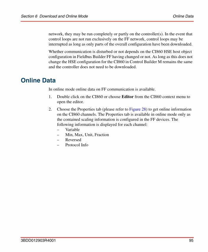
Section 6 Download and Online Mode Online Data
network, they may be run completely or partly on the controller(s). In the event that control loops are not run exclusively on the FF network, control loops may be interrupted as long as only parts of the overall configuration have been downloaded.
Whether communication is disturbed or not depends on the CI860 HSE host object configuration in Fieldbus Builder FF having changed or not. As long as this does not change the HSE configuration for the CI860 in Control Builder M remains the same and the controller does not need to be downloaded.
Online DataIn online mode online data on FF communication is available.
1. Double click on the CI860 or choose Editor from the CI860 context menu to open the editor.
2. Choose the Properties tab (please refer to Figure 28) to get online information on the CI860 channels. The Properties tab is available in online mode only as the contained scaling information is configured in the FF devices. The following information is displayed for each channel: – Variable– Min, Max, Unit, Fraction – Reversed– Protocol Info
3BDD012903R4001 95

Online Data Section 6 Download and Online Mode
3. Choose the Status tab (please refer to Figure 29) to get online information on
the CI860 channels. The following information is displayed for each channel:– Channel value– Forced– Variable value – Variable– Protocol Info
Forcing the channels is possible. For details please refer to the Control Builder M documentation. This tab also contains diagnostic data and information on the status of the FF HSE communication. For further information please refer to Statistic Channels on page 76.
Figure 28. CI860 Properties Tab in Online Mode
96 3BDD012903R4001
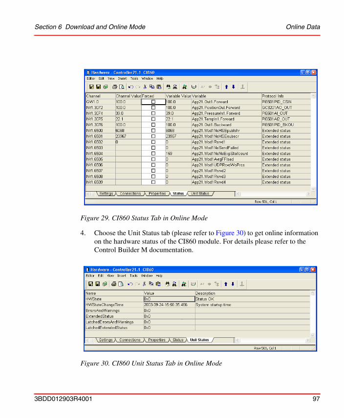
Section 6 Download and Online Mode Online Data
4. Choose the Unit Status tab (please refer to Figure 30) to get online information on the hardware status of the CI860 module. For details please refer to the Control Builder M documentation.
Figure 29. CI860 Status Tab in Online Mode
Figure 30. CI860 Unit Status Tab in Online Mode
3BDD012903R4001 97

Online Data Section 6 Download and Online Mode
5. Open your application (please refer to Figure 31) to get detailed information on all variables used in your application. This includes forward and backward components of the FF data types as well as status and forced information and FF parameters.
Figure 31. Application in Online Mode
98 3BDD012903R4001

Appendix A Application Example
This section provides a sample application configuration with cascaded control loops running both on FOUNDATION Fieldbus network and on the AC 800M controller.
Prerequisites and RequirementsThe following requirements must be met in order to be able to carry out the actions described in this section.
• An 800xA system has been created and started.
• The following system extensions have been added:
– AC 800M Connect,
– Fieldbus Builder FF.
• The Plant Explorer Workplace has been started.
• The user has Configure and Download permissions.
• An HSE subnet configuration created with Fieldbus Builder FF is available and has been uploaded to the Plant Explorer Workplace.
• A Control Network has been created in the Plant Explorer Workplace and the FFHSECommLib has been added. The Control Network contains an AC 800M controller with at least one CI860 module.
• Configured hardware is available and connected.
3BDD012903R4001 99
Sample Control Loop Appendix A Application Example
Sample Control LoopThe sample configuration features the following FF devices: an electro-pneumatic positioner and a pressure transmitter. The electro-pneumatic positioner has one FF function block: an analog output block. The pressure transmitter has three FF function blocks: a PID function block and two analog input function blocks (one for each channel, for example pressure and temperature). Using these devices a cascaded control loop will be configured. The pressure control loop will be running on the FF devices whereas the temperature control loop will be running on an AC 800M controller. I.e. the pressure control loop and the signals needed for the temperature control loop as well as the devices have to be configured with Fieldbus Builder FF. Please refer to Figure 32.
100 3BDD012903R4001
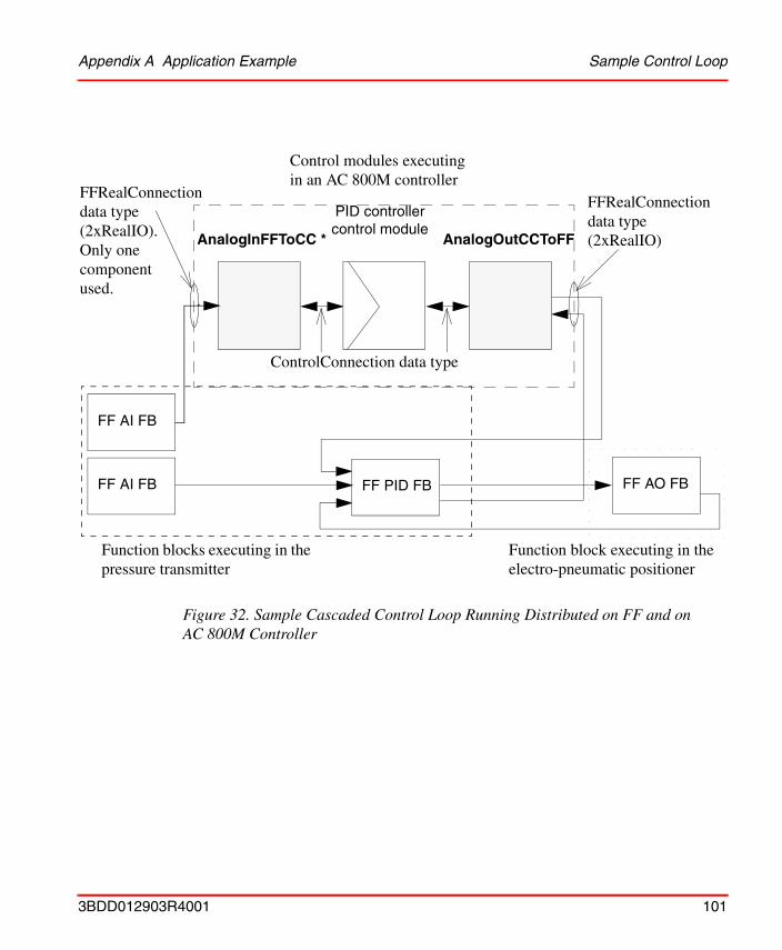
Appendix A Application Example Sample Control Loop
Figure 32. Sample Cascaded Control Loop Running Distributed on FF and on AC 800M Controller
FFRealConnection data type (2xRealIO). Only one component used.
ControlConnection data type
FFRealConnection data type(2xRealIO)AnalogOutCCToFFAnalogInFFToCC *
FF PID FB
PID controller control module
Control modules executing in an AC 800M controller
Function block executing in the electro-pneumatic positioner
FF AO FB
Function blocks executing in the pressure transmitter
FF AI FB
FF AI FB
3BDD012903R4001 101
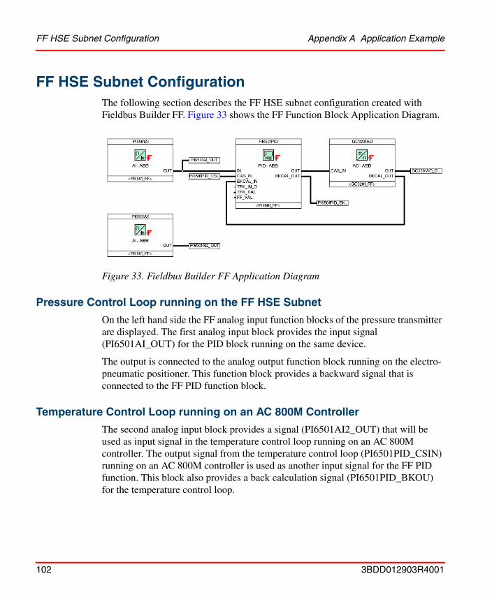
FF HSE Subnet Configuration Appendix A Application Example
FF HSE Subnet ConfigurationThe following section describes the FF HSE subnet configuration created with Fieldbus Builder FF. Figure 33 shows the FF Function Block Application Diagram.
Pressure Control Loop running on the FF HSE Subnet
On the left hand side the FF analog input function blocks of the pressure transmitter are displayed. The first analog input block provides the input signal (PI6501AI_OUT) for the PID block running on the same device.
The output is connected to the analog output function block running on the electro-pneumatic positioner. This function block provides a backward signal that is connected to the FF PID function block.
Temperature Control Loop running on an AC 800M Controller
The second analog input block provides a signal (PI6501AI2_OUT) that will be used as input signal in the temperature control loop running on an AC 800M controller. The output signal from the temperature control loop (PI6501PID_CSIN) running on an AC 800M controller is used as another input signal for the FF PID function. This block also provides a back calculation signal (PI6501PID_BKOU) for the temperature control loop.
Figure 33. Fieldbus Builder FF Application Diagram
102 3BDD012903R4001
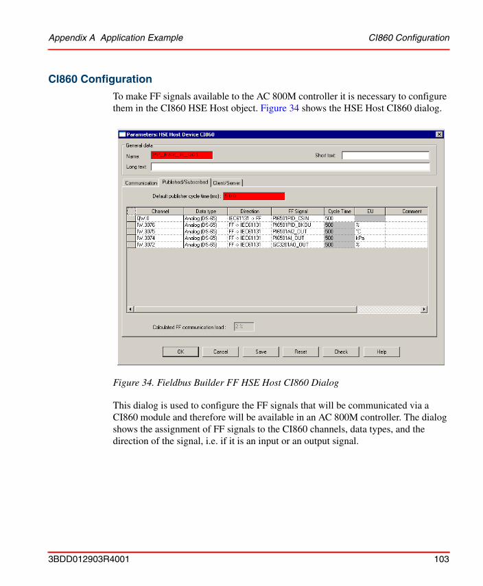
Appendix A Application Example CI860 Configuration
CI860 Configuration
To make FF signals available to the AC 800M controller it is necessary to configure them in the CI860 HSE Host object. Figure 34 shows the HSE Host CI860 dialog.
This dialog is used to configure the FF signals that will be communicated via a CI860 module and therefore will be available in an AC 800M controller. The dialog shows the assignment of FF signals to the CI860 channels, data types, and the direction of the signal, i.e. if it is an input or an output signal.
Figure 34. Fieldbus Builder FF HSE Host CI860 Dialog
3BDD012903R4001 103
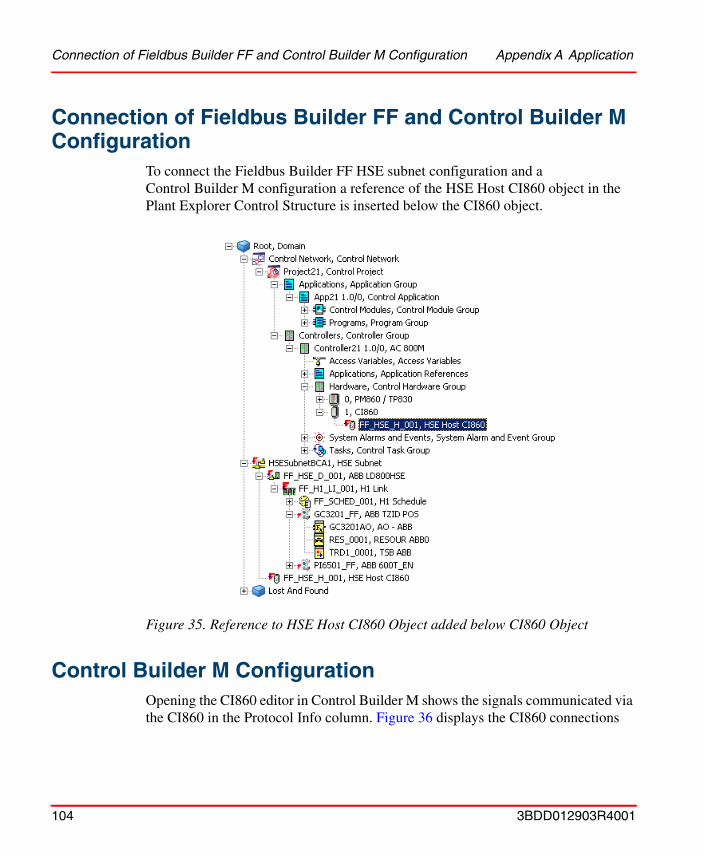
Connection of Fieldbus Builder FF and Control Builder M Configuration Appendix A Application
Connection of Fieldbus Builder FF and Control Builder M Configuration
To connect the Fieldbus Builder FF HSE subnet configuration and a Control Builder M configuration a reference of the HSE Host CI860 object in the Plant Explorer Control Structure is inserted below the CI860 object.
Control Builder M ConfigurationOpening the CI860 editor in Control Builder M shows the signals communicated via the CI860 in the Protocol Info column. Figure 36 displays the CI860 connections
Figure 35. Reference to HSE Host CI860 Object added below CI860 Object
104 3BDD012903R4001
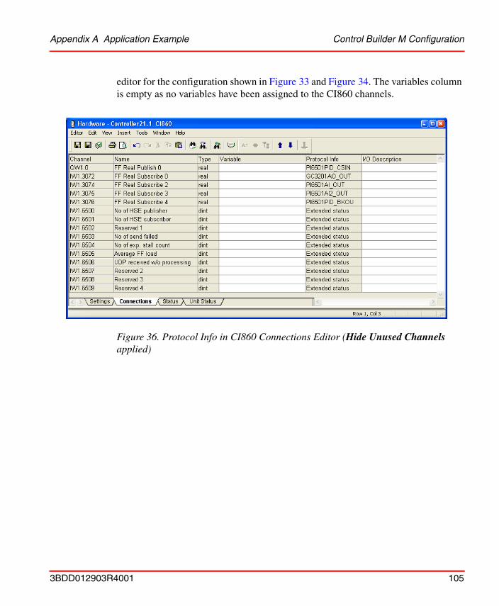
Appendix A Application Example Control Builder M Configuration
editor for the configuration shown in Figure 33 and Figure 34. The variables column is empty as no variables have been assigned to the CI860 channels.
Figure 36. Protocol Info in CI860 Connections Editor (Hide Unused Channels applied)
3BDD012903R4001 105
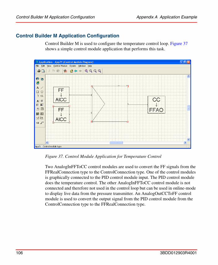
Control Builder M Application Configuration Appendix A Application Example
Control Builder M Application Configuration
Control Builder M is used to configure the temperature control loop. Figure 37 shows a simple control module application that performs this task.
Two AnalogInFFToCC control modules are used to convert the FF signals from the FFRealConnection type to the ControlConnection type. One of the control modules is graphically connected to the PID control module input. The PID control module does the temperature control. The other AnalogInFFToCC control module is not connected and therefore not used in the control loop but can be used in online-mode to display live data from the pressure transmitter. An AnalogOutCCToFF control module is used to convert the output signal from the PID control module from the ControlConnection type to the FFRealConnection type.
Figure 37. Control Module Application for Temperature Control
106 3BDD012903R4001
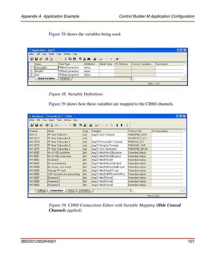
Appendix A Application Example Control Builder M Application Configuration
Figure 38 shows the variables being used.
Figure 39 shows how these variables are mapped to the CI860 channels.
Figure 38. Variable Definitions
Figure 39. CI860 Connections Editor with Variable Mapping (Hide Unused Channels applied)
3BDD012903R4001 107
Diagnostic Info and Online Data Appendix A Application Example
As the FFRealConnection data type contains a forward and a backward component similar to the ControlConnection data type one of the components must be chosen according to the direction of the signal flow.
I.e. to access the temperature output signal of the pressure transmitter which is available on the CI860 input channel IW1.3075 the forward component of the TempIn1 variable must be mapped to this channel. The forward component of the PressureIn1 signal is mapped to the input channel IW1.3075. The back calculation signal from FF PID function block which is available on the input channel IW1.3076 is mapped to the backward component of the variable Out1. The forward component of the variable Out1 is mapped to the CI860 output channel QW1.0.
Diagnostic Info and Online DataAfter the sample configuration has been downloaded to the HSE subnet and to the AC 800M Fieldbus Builder FF and Control Builder M provide online data.
Fieldbus Builder FF HSE Subnet Application
Figure 40 shows the Fieldbus Builder FF application in commissioning (online) mode. Online data is available, if the cursor is placed on a function block pin respectively a signal. Double-clicking a function block opens a dialog that provides current and configured values for all FF function block parameters. Please refer to Figure 41.
108 3BDD012903R4001
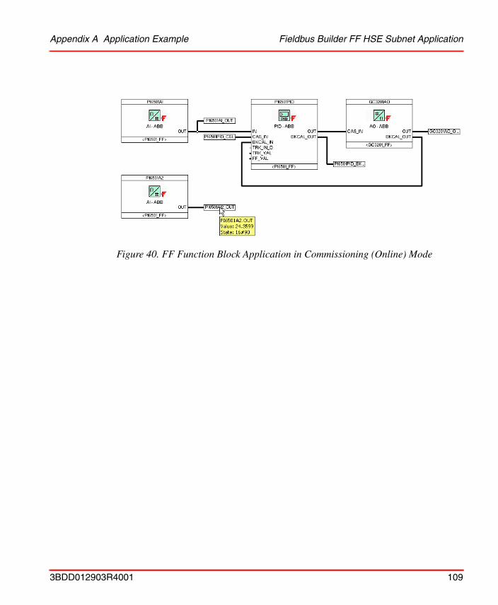
Appendix A Application Example Fieldbus Builder FF HSE Subnet Application
Figure 40. FF Function Block Application in Commissioning (Online) Mode
3BDD012903R4001 109

Control Builder M Application Appendix A Application Example
Control Builder M Application
Figure 42 shows the Control Builder M control module diagram in online mode. Clicking a control module opens a faceplate with current values. Faceplates for AnalogInFFToCC and AnalogOutCCToFF provide easy access to FF status information.
Figure 41. FF Function Block in Commissioning (Online) Mode
110 3BDD012903R4001
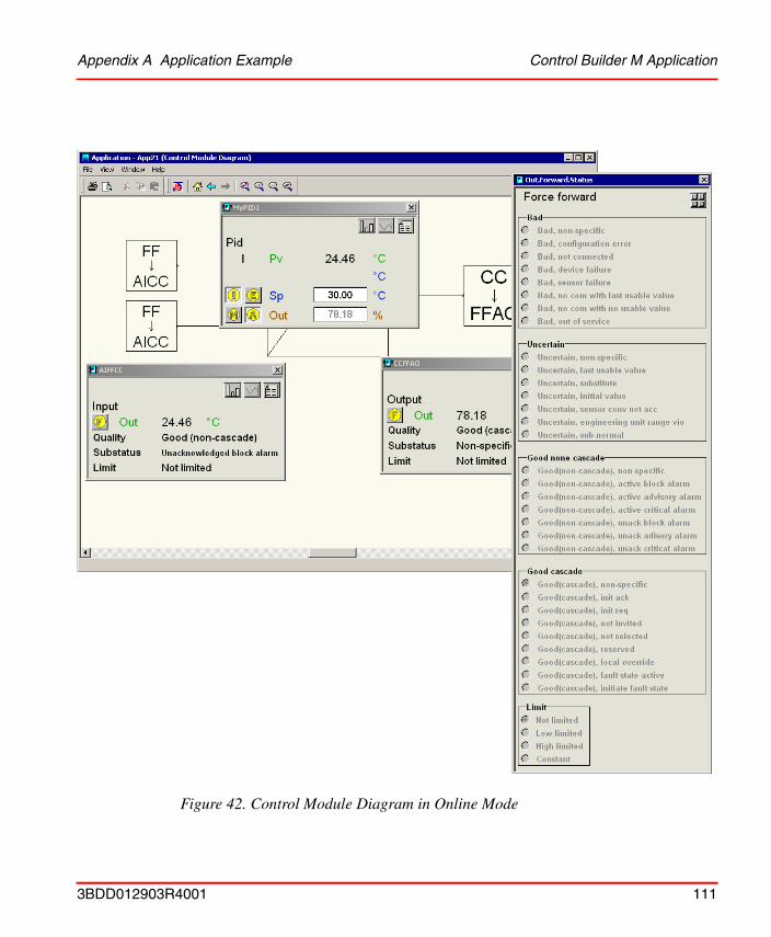
Appendix A Application Example Control Builder M Application
Figure 42. Control Module Diagram in Online Mode
3BDD012903R4001 111
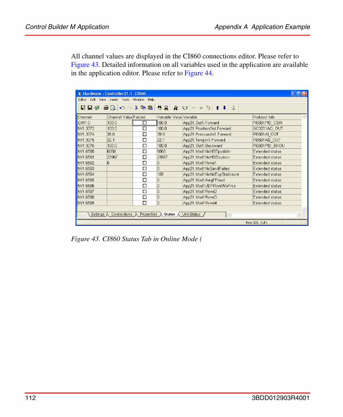
Control Builder M Application Appendix A Application Example
All channel values are displayed in the CI860 connections editor. Please refer to Figure 43. Detailed information on all variables used in the application are available in the application editor. Please refer to Figure 44.
Figure 43. CI860 Status Tab in Online Mode (
112 3BDD012903R4001
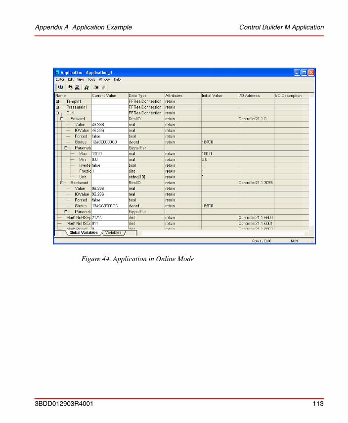
Appendix A Application Example Control Builder M Application
Figure 44. Application in Online Mode
3BDD012903R4001 113
Control Builder M Application Appendix A Application Example
114 3BDD012903R4001

INDEX
AAC 800M Hardware 54Analog Handling 80AnalogInFFToCC 81AnalogOutCCToFF 81, 83Aspect Systems 31Aspects
FF Management 57FFUpload 57
BBackward Calculation 36BoolIOToFFOut 86, 88
CCI860 40CI860 Connections Editor
Connections Tab 73Settings Tab 56Status Tab 57Unit Status Tab 57
CI860 IP Address Change 93Client Server Network 39, 43
Configuration 50Client/Server 70Configuration 47
Workflow 48Configuration Changes 33, 94Configuration Data 31Configuration Work Flow 48Connect HSE Subnet 59Connect Library 78
Connections Tab 73Connectivity Server FF 39Control Builder M 39Control Modules 77Control Network 40, 43
Configuration 50Control Structure 32, 60
DData Types 33
BoolIO 33, 75DwordIO 33, 75RealIO 33, 75
Data types 71Diagnostic Data 76, 96Digital Handling 86Dimensioning Guidelines 45Download 31, 91
HSE Subnet 91download 91DwordIOToFFOut 87, 89
EEngineering Workplace 39
FFF HSE Communication Library 78FF Management Aspect 58FFBoolConnection 88FFDWordConnection 89FFHSECommLib 78FFRealConnection 82
3BDD012903R4001 115
Index
FFToBoolIOIn 86 to 87FFToDwordIOIn 87, 89FFUpload Aspect 57Fieldbus Builder FF 39, 57Forward Calculation 36Function Blocks 77
HH1 Links 44HSE Network
Configuration 51HSE Subnet 43HSE Subnet Connection 59
II/O Channels 73, 75Inconsistent Configuration 94IP Address 50
LLD 800HSE 40Linking Device 40
NNetwork Configuration 49
OOnline Data 95OPC Server FF 39Operator Workplace 39
PPlant Explorer Workplace 29, 31 to 32Publisher/Subscriber 70
RRedundant Network Configuration 50Reference of HSE Host CI860 Object 32, 61
SSettings Tab 56Signal Mapping 72Statistic Channels 76Status Handling 36, 72Status Tab 57Subnet Connection
Change 66Subnet mask 50System Structure 39
UUnit Status Tab 57
WWorkflow 11, 48
116 3BDD012903R4001


3BDD012903R4001 October 2004Copyright © 1999 - 2004 by ABB., Printed in Sweden, All Rights Reserved® Registered Trademark of ABB.™ Trademark of ABB.
Automation Technology ProductsMannheim, Germanywww.abb.de/processautomationemail: [email protected]
Automation Technology Products Västerås, Swedenwww.abb.com/processautomationemail: [email protected]
Automation Technology ProductsWickliffe, Ohio, USAwww.abb.com/processautomationemail: [email protected]
http://www.abb.com/control