2016 Deloitte Oil & Gas Conference Oil, Gas, and Geopolitics: The ...

Precision Polymer Engineering Ltd
High PerformanceSealing Solutionsfor the
Oil & Gas industry

EnDura® and Perlast® are registered trademarks of Precision Polymer Engineering Ltd
Acknowledgement of other trademarks used throughout this brochure:
Aflas® - Asahi Glass Company Limited, PEEK® - Victrex Plc, Ekonol® - Saint-Gobain Advanced Ceramics Corporation, Viton® - DuPont Performance Elastomers.
2
Precision Polymer Engineering Limited
Precision Polymer Engineering Ltd
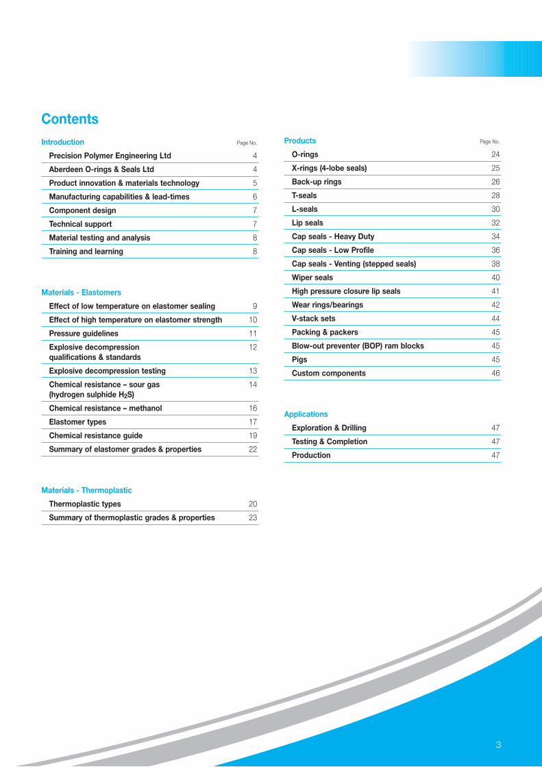
ContentsIntroduction Page No.
Precision Polymer Engineering Ltd 4
Aberdeen O-rings & Seals Ltd 4
Product innovation & materials technology 5
Manufacturing capabilities & lead-times 6
Component design 7
Technical support 7
Material testing and analysis 8
Training and learning 8
Materials - Elastomers
Effect of low temperature on elastomer sealing 9
Effect of high temperature on elastomer strength 10
Pressure guidelines 11
Explosive decompression 12qualifications & standards
Explosive decompression testing 13
Chemical resistance – sour gas 14(hydrogen sulphide H2S)
Chemical resistance – methanol 16
Elastomer types 17
Chemical resistance guide 19
Summary of elastomer grades & properties 22
Materials - Thermoplastic
Thermoplastic types 20
Summary of thermoplastic grades & properties 23
Products Page No.
O-rings 24
X-rings (4-lobe seals) 25
Back-up rings 26
T-seals 28
L-seals 30
Lip seals 32
Cap seals - Heavy Duty 34
Cap seals - Low Profile 36
Cap seals - Venting (stepped seals) 38
Wiper seals 40
High pressure closure lip seals 41
Wear rings/bearings 42
V-stack sets 44
Packing & packers 45
Blow-out preventer (BOP) ram blocks 45
Pigs 45
Custom components 46
Applications
Exploration & Drilling 47
Testing & Completion 47
Production 47
3

4
Introduction
Precision Polymer Engineering Ltd (PPE) has been supplying high performance sealsinto the oilfield industry for over 30 years. During this time PPE has earned an enviablereputation for being a highly responsive and reliable partner of choice with some of thefastest manufacturing lead-times in the sealing industry.
Combining innovative design, uncompromising quality and the latest elastomer technologywith specialist in-house material formulation, tool-making and state-of-the-art manufacturingfacilities, PPE delivers high performance components quickly and effectively.
With sales operations located in UK, Europe, USA and Asia, PPE provides customerswith world-class sealing solutions around the globe.
Aberdeen O-rings & Seals Ltd (AOS), part of the PPE Group of Companies, isconveniently located in Aberdeen to provide a first-class service to the oil and gasindustry. AOS stocks and distributes one of the widest range of sealing components inScotland. Well known for rapid response times, AOS has many years expertise andindustry ‘know-how’ to help solve the most demanding sealing challenges.
All the products and support services detailed in this brochure are available throughboth Aberdeen O-rings & Seals Ltd and Precision Polymer Engineering Ltd.
Three core competencies set PPE and AOS apart from the competition:
• unique, market leading, high performance materials
• advanced design and manufacturing capabilities
• excellent technical support and customer service.
Through these core competencies PPE and AOS provide customers with a competitiveadvantage which is demonstrated by the benefits listed below.
Benefits of PPE/AOS sealing solutions:
• Increased productivity through reduced maintenance and downtime
• Extended seal life expectancy and integrity
• Performance enabling materials to maximise equipment capabilities
• Reliable, rapid, industry-leading production lead times to support fast-paced oilfield operations especially in emergency situations
• Machined elastomer prototyping for speed, moulded elastomer production for cost effectiveness and repeatability
• World-class local customer service and technical support
• Professional development with PPE training courses and education
Precision Polymer Engineering Ltd

Oil exploration and extraction presents the most challenging conditions for elastomer seals; a combination of extreme temperatures, aggressivechemicals and gases, abrasive media, high pressure and destructive forces, subject seals to the harshest environments in the world.
In addition, the techniques employed to exploit reserves are becoming more complex, with operations moving to more remote locations anddeeper well depths, extending the operating demands on the seals even further.
Product Innovation and Materials Technology
Recognising the increasing challenges that face the oil and gasexploration and extraction industry, PPE operates at the forefront ofelastomer technology and is constantly pushing the boundaries todevelop the most technically advanced elastomer materialsavailable. Innovation is a way-of-life at PPE with in-house materialformulation and a continuous development programme that provideselastomers that not only keep pace with the current needs of theoilfield industry, but look to future requirements.
The EnDura® range of elite materials has been specificallydeveloped for use in downhole, surface and subsea oilfieldequipment and offers excellent explosive decompression (ED)resistance. The range includes unique material grades that providethe ultimate in chemical resistance, mechanical properties and lowtemperature performance.
5
Superior sealing solutions for borehole seismic equipmentA leading international seismic equipment manufacturer carried out comparative tests on EnDura® V91J, V91A and various competitor O-rings. The O-rings weresubjected to typical operating conditions of temperatures between -40°C (-40°F) and +230°C (+446°F) and pressures up to 207 MPa (30,000 psi). The EnDura® V91J andV91A O-rings outperformed all other materials tested with a significant increase in service life achieved. The manufacturer commented that superior materials, excellentquality and short manufacturing lead-times made PPE their seal manufacturer of choice.
PPE seals provide performance advantage for hydraulic R.E.D.A principal designer, manufacturer and supplier of downhole remote equalisation devices (R.E.D) was experiencing difficulties meeting ISO 14310 Grade V1 of the NORSOKStandard D-010 due to seal failure. The V1 validation involves the hydraulic R.E.D being tested to 52 MPa (7,500 psi) differential pressure within a temperature interval of75°C (167°F) and 4°C (39°F), over four cycles. V95X was the first material to pass the test, going on to complete seven cycles without showing any signs of leakage. The superior compression set performance, high strength and extrusion resistant properties of V95X provided the OEM with a unique competitive advantage.

6
Manufacturing capabilities
Operating from a purpose-built 6,000 sq.m. (64,500 sq.ft.)manufacturing facility equipped with the some of the most modernproduction apparatus in the world, PPE manufactures seals to thehighest quality standards to ensure repeatable performance in the field.Investment in one of the world’s largest moulding presses availableenables PPE to offer fully moulded O-rings and formed seals up to 2.5metres (8ft) diameter, manufactured on a single tool in one pressingaction. This provides the most accurate part dimensions and highestquality components that are far superior to jointed or cord seals.Accredited to ISO9001:2000, full traceability on elastomer materials isavailable during every manufacturing process through to finishedcomponents.
Rapid manufacturing lead-times
PPE and AOS understand that the oilfield industry demands thehighest level of service and responsiveness. Our in-house tool-making department and production facilities contain the latest and most efficient equipment in the world which results in rapidmanufacturing capabilities. If the required component is not available from our extensive stock, it can be manufactured within the shortest lead-times in the industry.
For time critical and emergency breakdown situations PPE and AOSoffer a 48-hour rapid manufacturing service. This premium serviceaims to manufacture and despatch parts from our production facilityin Blackburn within 48 hours of receipt of order (based on a Monday-Friday timeframe). Size and material restrictions apply, pleasecontact your local sales office for further details.
Rapid redesign of compressor seals for North Sea platformWhen a compressor used in transporting gas from a North Sea gas platform to onshore storage facilities failed unexpectedly, PPE were contacted and tasked with replacingthe failed scarf-jointed, cord seal with a more reliable seal. Within 48 hours PPE’s rapid response service designed and manufactured a 1.2m diameter O-ring made fromexplosive decompression resistant FKM elastomer. As a result, the new higher quality seal has provided longer production up-times and eliminated the unpredictability ofusing the previous jointed cord seals.
Critical seals manufactured, tested and delivered to offshore platform in just 4 hoursAberdeen O-rings and Seals (AOS) recently came to the rescue of a blue-chip oil and gas service company with their fast response time and extensive stocks. The customerhad a twelve-hour window to source, pressure test and deliver to an offshore platform ED resistant O-rings for valves operating in high temperature conditions.
After a swift visit to the customer’s premises to evaluate the valve and application, AOS engineers were able to recommend the correct EnDura® Z95X O-rings – suppliedfrom stock in Aberdeen. In addition, new PTFE ball seats and PEEK wear seats were manufactured using the rapid production service. The time taken to solve the problemfrom initial contact was just 4 hours, saving the customer thousands of pounds in production downtime.

7
Component design
Problem solving is central to PPE’s culture, providing customers withoptimal design solutions which exceed expectations. PPE engineerscan offer a range of services for the design of custom engineeredcomponents. From expert advice on existing designs, to a completedesign project working to customer specifications, with many yearsexperience, PPE engineers can design custom shapes and profiles tomeet any requirements.
CAD drawings are accepted from customers in almost any softwareformat, combined with in-house 3D modeling and analyticalbehavioural-predictive tools such as FEA (finite element analysis),allow PPE to explore a broad range of “what-if” scenarios, ensuringthe seal functionality is right first time, every time.
See page 46 for more details.
Services
New design of rotary wiper seal provides improved consistency and reliabilityA leading well intervention service company was experiencing inconsistent performance from their rotary wiper seal. The tolerances of the existing design were found to be causing theproblem. Working closely with PPE design teams, the critical performance criteria was identified and finite element analysis (FEA) facilitated design optimisation. This analysis allowedrealistic tolerances to be applied, switching the production process from machined parts to moulded seals which resulted in increased consistency and reliability in application.
Technical support
Support and expert technical advice are always available from PPEand AOS. Our engineers and material technologists provide supporton component design, material selection and compatibility, testingand analysis. Our consultancy service and field support includes on-site assistance with problem solving and troubleshooting.
Online tools and Engineers resource
MyPPE is an exclusive online portal available on the PPE website(www.prepol.com) which provides useful information on everyaspect of elastomer sealing. An invaluable technical resource forEngineers, MyPPE includes chemical compatibility data and materialselector, a hardware wizard which identifies the best fit standardsized O-ring for given groove dimensions and PPELive.
PPELive allows registered users to automatically generate anddownload standard seal components online and import 3D CADmodels and 2D drawings directly into any software package.Alternatively drawings and models can be emailed directly to users.

8
Services
Material testing and analysis
PPE offers an extensive range of independent testing andconsultancy services for companies and organisations which arelooking for assistance in investigating polymers materials of any sort.In partnership with the Materials Characterisation Centre (MCC)which is equipped with the latest state-of-the-art test apparatus,PPE’s Material Technology Department provides a range of servicesincluding; material analysis, product development, characterisation,testing, evaluation and detailed analysis of polymeric materials.
Typical examples of the type of work undertaken are:
- Failure analysis
- Chemical compatibility testing
- Thermal analysis
- Mechanical evaluation
- High pressure leak testing
- Explosive decompression testing (see page 13 for more details)
Training and learning
PPE and AOS offer customised training courses which are tailored tosealing applications experienced within the oil and gas industry. Ourexperts will provide delegates with a wealth of knowledge relating topolymer and sealing technology, from a basic level up to advancedand specialist subjects.
Courses are held at PPE’s purpose-built training centre in Blackburn,convention centres located in Aberdeen or at delegates’ ownbusiness premises (subject to a minimum group size).

9
MaterialsElastomers
PPE and AOS offer a wide range of high performance elastomer materials for various sealing applications in the oil and gas industry. Many ofthese unique materials have been developed to offer specific characteristics including; the ultimate in chemical resistance, mechanicalproperties, high pressure capability, explosive decompression (ED) resistance and industry-leading low and high temperature performance.
Effect of low temperature onelastomer sealing
Low temperature performance of elastomer seals isbecoming more important with the commercialisationof oilfields in cold locations, such as in Alaska, theNorth Sea and Russia. Traditionally, FKM seals havenot been recommended for low temperature dynamicapplications below -30°C (-22°F). This is due to theGlass Transition Temperature (Tg) of most lowtemperature ED resistant FKM elastomer formulations.The Tg is the temperature at which an elastomerchanges its physical properties from elastic andpliable to rigid and brittle and, as a result, loses itssealing ability. Any movement of either the seals or themating surfaces of the equipment at this temperaturecould result in damage to the seal surface in the formof cracking or splitting.
High pressure has the apparent effect of increasing the Tg of an elastomer; as a general rule, for every 5 MPa (725 psi) bar increase in pressure,the Tg increases by 1°C. This has significant implications for engineers involved in the selection of elastomer seals. For example, an elastomerhaving a Tg of -30°C (-22°F) at atmospheric pressure, would in effect have a Tg of only -20°C (-4°F) when the pressure acting on the seal isincreased to 50 MPa (7250 psi).
EnDura® V91A is the first low-temperature, explosive decompression resistant, FKM of its kind that is capable of retaining its elastomericproperties at temperatures as low as -46°C (-51°F). This revolutionary material allows engineers to extend the effective limit of their equipment in low temperature applications.
Seal integrity tests conducted by a prominent European ball valve manufacturer concluded that EnDura® V91A outperformed other competitor seals as well as PTFE andspring energised PTFE lip seals. The sealing performance of 2.62mm (0.103”) cross section EnDura® V91A O-rings was shown to be excellent with leak-free results. Usinga nitrogen/helium mix the O-rings maintained sealing integrity when subjected to temperatures of -40°C (-40°F) and pressures up to 28 MPa (4061 psi).
approximately 1 ˚C increase in GlassTransition Temperature (Tg) as a result of
each 725 psi increase in Pressure
12000
10000
8000
6000
4000
2000
0-40 -39 -38 -37 -36 -35 -34
Tg ( ˚C)
Pre
ssur
e (p
si)
-33 -32 -31 -30 -29 -28 -27
The Apparent Effect of Pressure on Glass Transition Temperature
10
ElastomersMaterials
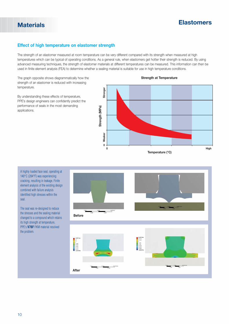
Effect of high temperature on elastomer strength
The strength of an elastomer measured at room temperature can be very different compared with its strength when measured at hightemperatures which can be typical of operating conditions. As a general rule, when elastomers get hotter their strength is reduced. By usingadvanced measuring techniques, the strength of elastomer materials at different temperatures can be measured. This information can then beused in finite element analysis (FEA) to determine whether a sealing material is suitable for use in high temperature conditions.
The graph opposite shows diagrammatically how thestrength of an elastomer is reduced with increasingtemperature.
By understanding these effects of temperature, PPE’s design engineers can confidently predict theperformance of seals in the most demandingapplications.
Temperature (°C)
Str
engt
h (M
Pa)
00
High
Wea
ker
Str
onge
r
Strength at Temperature
A highly loaded face seal, operating at140°C (284°F) was experiencingcracking, resulting in leakage. Finiteelement analysis of the existing designcombined with failure analysisidentified high stresses within the seal.
The seal was re-designed to reduce the stresses and the sealing materialchanged to a compound which retainsits high strength at temperature, PPE's V76F FKM material resolved the problem.
After
Before

11
MaterialsElastomers
Pressure Guidelines
High pressure sealing applications typically require robust highmodulus, high hardness materials. Conversely, softer, lower moduluselastomers are more compliant and better suited to low pressuresealing applications. Frequently elastomers are specified usinghardness. However this is a localised surface measure and does notdirectly relate to modulus which is a measure of a seal’s overallstiffness. Materials with higher modulus are more resilient to highpressure extrusion.
Combinations of pressure and clearance that lie to the right of thepertinent line will result in extrusion of an O-ring and the inclusion of a back-up ring, or use of a T-Seal or L-Seal is advised.
The chart opposite is a simplified representation of nitrile rubbersunder continuous use at 70°C (158°F). Elevated operatingtemperatures considerably weaken elastomers; therefore the abovechart is not applicable to ambient burst tests, or operation atextremes of temperature. The graph on page 10 shows the loss ofstrength with increasing temperature of elastomer materials.
Contact PPE for assistance in selecting the correct solution for your high pressure application.
Approximate Extrusion Pressure for a Given Diametral Clearance
Very High Pressure
General Purpose
Very Low Pressure
90
°IR
HD
100% M
odulus(M
Pa)
75
50
16
8
2
General Rules Governing Material Selection

12
A SUMMARY OF ED STANDARD TEST CONDITIONS
NORSOK TOTAL NACE MCCM710 GS PVV 142 TM0297 RGD-01
Specimen BS325 O-ring BS425 O-ring AS325 O-ring BS325
Constraint 20% compression 15% compression Optional 18% compression
Replication Three Four Nine Four
Fluid90/10 80/20 100% 90/10
CH4/CO2 CH4/CO2 CO2 CH4/CO2
Temperature 100, 150 or 200°C 75°C ± 2°C50, 100, 120, 150, 175,
100°Cor 230°C ± 3°C
Pressure 15, 20 or 30 MPa 19 ± 2 MPa 7, 17, 28, or 38 MPa 38 Mpa
Initial exposure period 72hrs 72hrs -- --
Soak period 24hrs 48hrs 24hrs 72hrs ± 4 hrs
Decompression Rate 2-4 MPa/min19 to 0 MPa
7 ±0.7 MPa/min 2 MPa/minin 90 secs
Dwell at ambient pressure 1hr 1hr -- --
Cycles 10 5 1 1
Elastomers
Explosive Decompression
Explosive Decompression (ED), also referred to as Rapid GasDecompression (RGD), is a failure mechanism of elastomer sealsthat is due to the rapid decompression of a gaseous media. Whenelastomer seals are exposed to high-pressure gas for a prolongedperiod the gas permeates into the seal material. When the externalpressure is reduced, the gas which is dissolved within the sealmaterial comes out of solution to form micro bubbles. As the gasexpands, it may permeate out of the seal material. However, if therate of decompression (and hence expansion) is high, gas which istrapped within the seal can cause fissuring and result in seal failure.
Explosive Decompression Standards
There are a number of international standards for testing elastomer materials in ED conditions, they include:
• NORSOK Specification M-710 Rev.2 Section 7.3/Annex B: “Qualification of non-metallic Sealing Materials and Manufacturers - Resistance to rapid gas decompression (RGD)”
• TOTAL General Specification GS PVV 142 Appendix 8 “Elastomer O-ring Seals Explosion Decompression Type Testing Procedure”
• NACE TM0297 “Effects of High-Temperature, High-Pressure Carbon Dioxide Decompression on Elastomeric Materials”
Materials
Elastomer seals affected by explosive decompression.

13
SUMMARY OF PPE/AOS MATERIALS TESTED TO THE REQUIREMENTS OF VARIOUS STANDARDS
NORSOK M710 TOTAL NACE MCC7.3 PVV 142 03/01
ED H2S RGD-01RGD Rev. 00
TM0297 TM0187
EnDura® V91J � � � � �
EnDura® V91A � � � � �
EnDura® G92E � �
EnDura® A90H � �
EnDura® Z95X � � � �
Z85L �
MaterialsElastomers
Explosive Decompression Testing
In partnership with PPE and AOS, the Materials Characterisation Centre (MCC) contains state-of-the-art ED test equipment which canpressurise seals of various geometries up to 70 MPa (10,000 psi) and can decompress over any desired cycle or time, whilst at temperatures of up to 300°C. Using this equipment, compounds can be developed and tested to overcome explosive decompression, with pressure,temperature, gas mixtures and pressure release cycles simulating actual field operation. The performance of seal types and grades can beconfirmed before installation.
With 3L accumulators, the ED test rigs have been designed to meet TOTAL, NACE and NORSOK test requirements with all temperatures,pressures, gas mixtures and depressurisation rates detailed therein. The O-ring carrier inserts are interchangeable to allow O-rings to be testedat various squeeze levels in face and piston geometries. This equipment also tests high-pressure sealing capability versus diametral clearanceand back-up ring performance and can test leak rates for fugitive emission testing.
ED TEST RIG CAPABILITIES
FROM TO
Pressure 0 70 MPa (10,000 psi)
Temperature Ambient 300°C (572°F)
Gases Non-sour gas
Geometries Face and piston
Squeeze As required
O-ring size: 70 MPa Not applicable 47mm outer diameter
35 MPa 40mm outer diameter 129mm outer diameter
O-ring cross section 1mm 15mm
Depressurisation rate As required
No. of test O-rings 1 3

14
AVERAGE COMPRESSION SET CHANGE AFTER EXPOSURE TO 10% H2S (measured within two hours)
Material Compression SetGrade change (%)
V91J (FKM) +10.0
V91A (FKM) +7.1
Z95X (HNBR) +15.9
AVERAGE COMPRESSION SET CHANGE AFTER EXPOSURETO 10% H2S (measured after 24hrs recovery at room temperature)
Material Compression SetGrade change (%)
V91J (FKM) +2.6
V91A (FKM) +5.1
Z95X (HNBR) +7.3
Chemical Resistance Tests
In addition to the ED test standards detailed earlier, a number of EnDura® elastomer grades have been tested in sour gas (H2S) and methanolfor chemical resistance.
Sour Gas (Hydrogen Sulphide H2S)
Hydrogen sulphide (H2S) is an aggressive species towards some elastomer compounds. Its main mode of action is to incorporate sulphur byway of additional cross-links between polymer chains. This in effect is a continuation of the cure cycle which many elastomers undergo in orderto prevent irreversible chain slippage when strained. Therefore, by increasing the amount of cross-linking, the elastomer becomes stiffer. Inextreme cases the resulting brittleness causes loss of sealing function.
EnDura® grades V91K (FKM), V91A (FKM) and Z95X (HNBR) have been independently tested by MERL (Materials Engineering ResearchLaboratory) and qualified according to NACE standard TM0187 (Chemical Ageing of Elastomeric Materials in sour liquid (H2S) environments).
Test conditions
10% H2S, 15% CO2 in methane gas, over a hydrocarbon/water liquid phase, as the exposure medium, 10 MPa (1,450 psi) pressure,temperature of 100°C (212°F) for the duration of 100 hours.
The compression set of the three sample specimens was tested (using ASTM D395 method B) within two hours of removal from the testchamber and again after 24hrs recovery at room temperature. Compression set is the measure of the inability of an elastomer to recover fullyfrom a deformed state to its original state when the strain is removed. Compression set is a property which reflects the ability of a seal tofunction and which is adversely affected by temperature.
Results
V91A, V91J and Z95X performed satisfactorily after exposure to a fluid mixture containing 10% H2S and hydrocarbon solvent. Compression set was low throughout with further reductions occurring after 24 hours recovery at room temperature.
ElastomersMaterials

15
Results from an independent study conducted in H2S concentrations up to 64%, at elevated temperatures up to 220°C (428°F), suggest that peroxide-cured FKM elastomers (such as EnDura® V91J, V91K & V91A FKM grades) provide superior resistance to stiffening which causes aloss of sealability. It is important to note that the effect of sour gas may be combined with the effect of other chemicals the seal may be incontact with (i.e. aromatic hydrocarbons). This, combined with elevated temperatures and pressure, will significantly influence the rate at whichthe seal is affected.
Additional tests carried out on EnDura® gradePerlast® G92E showed that the tensile strengthof the perfluoroelastomer (FFKM) material was onlyminimally reduced (from 20 MPa to 16 MPa) afterbeing immersed in a 65% H2S / 35% CO2 gasmixture for 340 hours at 150°C (302°F).
This demonstrates this material’s ability to maintainits mechanical properties whilst providing excellentlong-term chemical resistance.
MaterialsElastomers
20
15
10MPa
5
00 340
Hours
G92E H2S 65%/CO2 35%, 150°C Tensile Strength

16
Elastomers
Methanol Immersion Tests
EnDura® grades V91J, V91K, V91A, Perlast® G92E and a leading competitor FKM grade were immersion tested in 100% methanol. The testused BS1806-214 size O-rings under room temperature conditions over a period of 580 hours.
Three specimens of each material were immersed in methanol liquid and measured for volume change (swell) at regular intervals. The amount of volume change was measured using ASTM D297 Test method.
Results
Perlast® G92E experienced the least swell as is expected for a perfluoroelastomer (FFKM). The EnDura FKM grades also performed very wellcompared to the leading competitor FKM which swelled by a further 4%.
TABLE OF RESULTS
Volume Change (%)No. of
EnDura® V91J EnDura® V91K EnDura® V91A Competitor Perlast® G92EHoursFKM FKM FKM FKM FFKM
24 2.3 2.2 3 3.8 0.1
72 3.3 3.2 3.3 4.2 0.3
168 4.1 4 3.9 6.8 0.3
360 5.8 5.6 5.8 8.4 0.6
580 6.8 6.6 6.1 10.2 0.9
Time (hours)
% V
olum
e C
hang
e
0
0 100 200 300 400 500 600 700
2
4
6
8
10
12
Competitor
V91J
V91K
V91A
G92E
Methanol Immersion at Room Temperature
Materials

17
MaterialsElastomers
Elastomer Types
EPDM
EPDM polymers exhibit outstanding resistance to weathering, ozone, water and steam. These rubbers have good chemical resistance and areparticularly recommended for use with phosphate ester based hydraulic systems. They are not suitable for use with mineral oils or petroleumbased fluids and are typically used in carbon storage applications.
Nitrile NBR
Nitrile is widely used throughout the oilfield industry due to it being less expensive than some other high performance materials. The propertiesof this copolymer are governed by the ratios of the two monomers acrylonitrile (ACN) and butadiene. The higher the ACN content, the higherwill be the resistance to aromatic hydrocarbons. Lower ACN content provides better low temperature flexibility. The most commonly specified,and the best overall balance for most applications is, therefore, 'medium nitrile'. General characteristics of NBRs include excellent resistance toaliphatic hydrocarbon oils, fuels and greases, very low gas permeability, good heat ageing properties and ozone resistance, improved tensileand abrasion strength, hardness, density and low compression set.
Hydrogenated Nitrile HNBR
HNBR elastomers are a saturated version of NBR, showing superior heat resistance. General properties include excellent wear resistance, high tensile strength, high hot-tear resistance, low compression set and very good ozone and weathering resistance. They also exhibit goodresistance to many oil additives, hydrogen sulphide and amines present in crude oil. HNBRs fill the gap between NBRs and FKMs in manyareas of application where resistance to heat and aggressive media are required simultaneously, and may therefore provide a lower costalternative to FKM elastomers.
Fluoroelastomer FKM
This class of rubber is available as a copolymer, terpolymer or tetrapolymer; the type determines the fluorine content (between 65% and 70%) and thus chemical resistance. General properties include excellent resistance to heat, aliphatic and aromatic hydrocarbons, chlorinated solvents, mineral and synthetic lubricants and petroleum fluids. FKMs have a clear superiority in O-ring sealing force retention over most other oil-heat resistant rubbers with the exception of perfluoroelastomers such as Perlast®. FKMs do show poor resistance to ethers, ketones, esters, amines and hydraulic fluids based on phosphate esters. Special compounds are required to provide suitable resistance to hot water, steam and wet chlorine.

18
Elastomers
Aflas FEPM or TFE/P
FEPM exhibits similar thermal stability to FKM elastomers, but better electrical resistance and a different chemical resistance profile. FEPMcompounds have the ability to resist a wide range of chemical combinations such as sour gas and oil, acids and strong alkalis, ozone andweather, steam and water, all hydraulic fluids, alcohols, amine corrosion inhibitors, water-based drilling and completion fluids and high pHcompletion fluids. However, they are not compatible with aromatic hydrocarbons, chlorinated hydrocarbons, organic acetates and organicrefrigerants.
Perfluoroelastomer FFKM
FFKMs exhibit outstanding high temperature properties and are the most chemically resistant elastomer available; effectively a rubber form ofPTFE. They are superior to FKM elastomers, showing continuous dry-heat resistance to 260°C (500°F), with extended performance to 330°C(626°F) for high temperature grades. They are extremely inert chemically and show excellent resistance to the majority of chemicals that attackother elastomers. Other notable properties include excellent resistance to oil-well sour gases, high temperature steam, low out-gassing under vacuum and good long-term high temperature compression set resistance.
Fluoroelastomer FKM (continued)
Copolymer, Terpolymer or Tetrapolymer
Fluoroelastomer or fluorocarbon (FKM/FPM) materials are available in three general types depending on their fluorine content and the number ofmonomers contained within the polymer.
FLUOROELASTOMER TYPES
Type Fluorine Content Advantages / Disadvantages
Contains two monomers (simple molecules from which polymers are built). General purpose, most common, most widely used for sealing. Best compression set and very
Copolymer (A/E) 65% - 65.5% good fluid resistance. Often referred to as 'A' and 'E' type grades.These are normally the least expensive types of compound.
Contains three monomers. Better fluid and oil/solvent resistance than copolymers but at the expense of poorer compression
Terpolymer (B or F) 67% set resistance.Often referred to as 'B' or ‘F’ type grades.‘F’ grades offer superior fluid resistance over ‘B’ grades.
Contains four monomers.Improved fluid, acid, solvent resistance over other types. Compression set better than terpolymers.These are sometimes known as 'G' grades.
Tetrapolymer (G) 67% - 69% In addition, certain tetrapolymers have good low-temperature flexibility. Tetrapolymers are the most expensive of the three types listed here.Tetrapolymer materials can also be referred to as GF, GLT and GFLT grades which correspond to Viton®, the registered trade name of DuPont’s FKM material.
GF – Good high temperature performance and chemical resistance but reduced mechanical properties and low temperature performance.
GLT – Improved low temperature performance but reduced chemical resistance.GFLT – Good all-round low/high temperature performance and chemical resistance.
Materials

19
MaterialsElastomers
PPE grade V91J V91K V91A V95X A90H Z95X Z85L N70M G75B G92E
Material type FKM FKM FKM FKM FEPM HNBR HNBR NBR FFKM FFKM
Acid 1 1 1 1 1 2 2 2 1 1
Alkanes 1 1 1 1 1 1 1 1 1 1
Amines 3 3 4 4 2 4 4 4 1 1
Base oil 1 1 1 1 1 1 1 1 1 1
Biocides 3 3 3 1 2 2 2 2 1 1
Biodiesel 1 1 1 1 1 2 2 3 1 1
Bioethanol 1 1 1 1 1 1 1 1 1 1
Chloride 1 1 1 1 1 1 1 1 1 1
Brine Bromide 1 1 1 2 1 2 2 3 1 1
Formate 2 2 2 3 1 3 3 3 1 1
Carbon Dioxide (CO2) 2 2 2 2 2 3 1 1 1 1
Cement 1 1 1 3 1 1 1 2 1 1
Corrosion Inhibitors 2 2 3 2 1 1 2 3 1 1
De-emulsifier (mud) 1 1 1 1 1 1 1 2 1 1
Defoamers 1 1 2 1 1 1 1 1 1 1
Dielectric fluid 1 1 1 1 1 1 1 1 1 1
Emulsifiers 1 1 2 1 1 2 1 2 1 1
Emulsion (oil and water) 1 1 2 2 1 1 2 1 1 1
Foaming agents 1 1 2 2 1 1 2 2 1 1
Acid 1 1 1 1 1 2 2 2 1 1
Chloride 1 1 1 1 1 1 1 2 1 1
Gravel packer fluid 1 1 1 1 1 1 1 1 1 1
Oceanic HW 443 2 2 2 2 1 2 2 2 1 1
Oceanic HW 500 1 1 2 2 1 2 2 2 1 1
Oceanic HW 525 1 1 2 1 1 2 2 2 1 1
Oceanic HW 540 1 1 2 1 1 2 2 2 1 1
<1% 1 1 1 2 1 1 1 3 1 1
<10% 2 2 2 2 1 2 2 3 1 1
<30% 2 2 2 3 1 3 3 4 1 1
Lost circulation fluids 1 1 1 1 1 1 1 1 2 2
Lubricants 1 1 1 1 1 1 1 1 1 1
Methane 1 1 1 1 1 1 2 1 1 1
Methanol 1 1 2 2 1 1 1 1 1 1
Mineral based oil 1 1 1 1 1 1 1 1 1 1
Water 1 1 1 1 1 1 1 1 1 1
Oil 1 1 1 1 1 1 1 1 1 1
Synthetic oil 2 2 3 3 2 2 1 3 1 1
Polyalkylene glycol 1 1 1 1 1 1 1 2 1 1
Poly-a-olefin 1 1 1 1 1 1 1 2 1 1
Poly-ol fire resistant ester 2 2 3 2 3 3 3 3 1 1
Sea water 1 1 1 1 1 1 1 1 1 1
Slurries 1 1 1 1 1 1 1 1 1 1
Synthetic biodegradeable ester 2 2 2 3 2 3 3 3 1 1
Thinners/dissolvers 1 1 1 2 1 2 2 2 1 1
Viscosifiers 1 1 1 1 1 1 1 1 1 1
Well cleaning fluids 2 2 2 1 1 1 2 2 1 1
Brine
Formation water
Hydraulic control fluid
Hydrogen Sulphide (H2S)
Mud
Chemical Resistance Guide Key: 1- Excellent 2 - Good 3 - Doubtful 4 - Do not use

20
Thermoplastic
Polyurethane (AU)
Polyurethanes are thermoplastic resins (sometimes classed as elastomers) which exhibit excellent mechanical and physical properties whilstproviding outstanding resistance to petroleum oils and hydrocarbon fuels. Polyurethane rubbers are used where high abrasion resistance andoil/solvent resistance are required simultaneously. In all applications, consideration should be given to hydrolysis and limited heat resistance.
PEEK
PEEK (polyetheretherketone) is a resilient, semicrystalline thermoplastic with extraordinary mechanical properties. The material is highly resistantto wear, hydrolysis, thermal degradation and experiences less creep compared to PTFE. PEEK also exhibits good chemical resistance in bothorganic and aqueous environments. PEEK material grades are available as ‘virgin’ (non-filled) or various filled grades, which provide enhancedphysical characteristics.
T55B Virgin (non-filled)Thermoplastic polymer with excellent mechanical properties at high temperatures. PEEK offers excellent chemical resistance, very low moistureabsorption and excellent mechanical strength and stiffness. In dynamic applications, PEEK offers inherently good wear and abrasion resistance.PEEK is unaffected by continuous exposure to hot water and steam.
T57B Glass filledThe addition of a glass filler increases the flexural modulus, compressive strength and reduces the expansion rate. The strength at highertemperatures is increased and it offers better resistance to creep.
T58B Carbon filledCarbon fibre fillers enhance the compressive and tensile strength over glass filled grade. The stiffness is also increased, whilst offering improvedwear resistance and load bearing capabilities at elevated temperatures.
T56B Bearing gradeEnhanced compressive strength, wear rate, PV limit and reduced friction over standard PEEK.
Materials

21
MaterialsThermoplastic
PTFE
PTFE (polytetrafluoroethylene) is generally considered a thermoplastic polymer; it has the lowest coefficient of friction of any solid engineeringmaterial. PTFE material grades are available as ‘virgin’ (non-filled) or various filled grades, which provide enhanced physical characteristics.
T99W Virgin (non-filled)Thermally stable up to 260˚C while still possessing a certain compressive plasticity at temperatures near to absolute zero. Virgin PTFE ispractically inert against all known elements and compounds, attacked only by alkaline metals in the elementary state, halogenides, CF3 and byelementary fluorine at high temperatures and pressures. PTFE is quite flexible and resistant to breaking when subject to tensile or compressionstresses.
However, below the yield point, part of the resulting deformations remains after the discontinuance of the stresses, with the result that certainstrains are induced in the piece. Virgin PTFE has a low coefficient of friction, but is weakened in dynamic applications by its wear rate, (whichcan be improved with fillers). Hardness varies between 50 and 60 Shore D.
T99G 25% Glass-filledWear properties and deformation strength under load are improved. The electrical and chemical characteristics remain substantially unchanged,but glass itself has a rather poor resistance against alkalis and is easily attacked by hydrofluoric acid. The coefficient of friction is slightlyincreased.
T99GM 15% Glass / 5% Molybdenum-filledWear properties and deformation strength under load are improved. The electrical and chemical characteristics remain substantially unchanged,but glass itself has a rather poor resistance against alkalis and is easily attacked by hydrofluoric acid and increases the coefficient of friction,molybdenum disulphide (MoS2) is added to compensate this effect.
T99C 25% Carbon-filledThe carbon improves the wear and deformation strength to a considerable degree, but substantially changes the electrical properties. It hasbetter thermal conductivity than glass filler and offers a lower wear rate of the opposing surfaces due to being less abrasive. Carbon fibre offersgood properties in water whilst remaining chemically inert and resistant to hydrofluoric acid.
T99X 15% Graphite-filledGraphite lowers the coefficient of friction. It improves the deformation under load, strength and, to a minor degree, the wear properties whencompared to virgin PTFE.
T99B 40% Bronze-filledBronze-filled PTFE has the best wear properties, remarkable deformation strengths and good thermal conductivity, but poor electricalcharacteristics and chemical resistance. Not recommended in applications involving aluminium or soft metal rods/bores, heavy side-loading or in the presence of water.
T99E 10% Ekonol®-filledEkonol® is a polyester which, combined with PTFE, produces a material that is extremely wear resistant. T99E offers the ultimate in wear resistance for seals operating in the toughest conditions without being abrasive to mating surfaces.

22
Elastomers
PPE Material HardnessCompression Set Tensile 100% Elongation
OperatingH2S*
ED/RGDgrade Type (°RHD)
Strength Modulus at BreakTemperature Steam Oil Gas
(%)ResistantConditions (%) (MPa) (MPa) (%)
A70HFEPM
75 24hrs @ 200°C 35 18.6 3.5 250 -5 to +250°C � � � <30
A90H 93 70hrs @ 200°C 35 19 17.5 130 0°C to +250°C � � � <30 �
G75BFFKM
78 72hrs @ 200°C 18 19.2 12 160 -15°C to +325°C � � � >30
G92E 90 24hrs @ 200°C 24 26 25 110 -15°C to +260°C � � � >30 �
N70M 70 24hrs @ 100°C 25 14 5 350 -40°C to +120°C � �
N73B 71 24hrs @ 70°C 6 17.2 5 350 -35°C to +120°C � �
N75L NBR 70 24hrs @ 100°C 15 12 4 275 -60°C to +135°C � �
N90M 90 24hrs @ 70°C 25 12.5 12.5 100 -30°C to +120°C � �
N93B 88 24hrs @ 70°C 6.5 19 11 275 -35°C to +120°C � �
V71C 72 24hrs @ 200°C 18 13 4 180 -51°C to +225°C � � � <1
V74C 75 72hrs @ 200°C 9.5 12.5 6 220 -18°C to +225°C � � <1
V75B 70 24hrs @ 200°C 14 12.1 6 215 -20°C to +200°C � � <1
V75J 75 24hrs @ 200°C 11.6 17.4 6 300 -15°C to +200°C � � � <5
V76E 75 24hrs @ 200°C 20 18.4 6.1 180 -20°C to +206°C � � � <10
V76F FKM 71 72hrs @ 200 °C 12 27.4 19 210 -15°C to +250°C � � � <10
V91A 90 24hrs @ 200°C 12 14 6.5 130 -46°C to +225°C � � � <5 �
V91J 90 24hrs @ 200°C 24 24 11 210 -17°C to +225°C � � � <5 �
V91K 90 24hrs @ 200°C 24 16 7 220 -35°C to +225°C � � � <5 �
V95F 90 24hrs @ 200°C 50 10 10 100 -10°C to +200°C � � <1
V95X 92 24hrs @ 200°C 15 16 10 120 -20°C to +200°C � � <1 �
Z70B 70 24hrs @ 150°C 15 16.3 10 250 -30°C to +180°C � � � <5
Z73B 70 24hrs @ 135°C 12 16.3 8.5 250 -30°C to +180°C � � � <5
Z75LHNBR
78 22hrs @ 150°C 30 15 8 205 -40°C to +180°C � � � <10
Z85B 80 24hrs @ 135°C 21 20.5 12.3 275 -30°C to +180°C � � � <5
Z85L 85 24hrs @ 150°C 21 18.3 16 195 -40°C to +160°C � � � <10 �
Z95X 89 24hrs @ 150°C 20 32 18 264 -25°C to +180°C � � � <5 �
Elastomers
Materials
Chemical Resistance
*H2S data is for general guidance only, please contact the PPE Technical Department for further advice.
23
MaterialsElastomers
PPE Material HardnessCompression Set Tensile 100% Elongation
OperatingGrade Type
Description(Shore A)
Strength Modulus at BreakTemperatureConditions (%) (MPa) (MPa) (%)
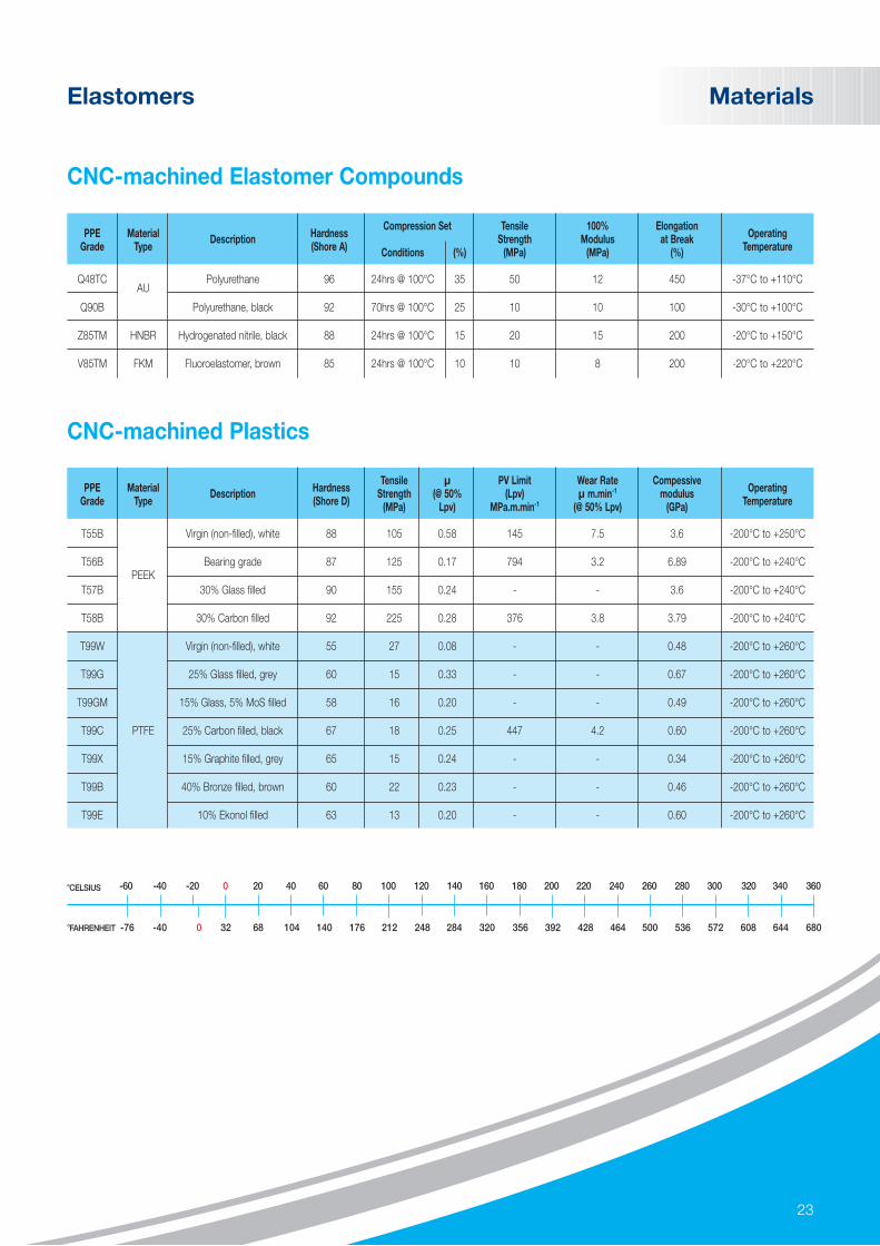
Q48TCAU
Polyurethane 96 24hrs @ 100°C 35 50 12 450 -37°C to +110°C
Q90B Polyurethane, black 92 70hrs @ 100°C 25 10 10 100 -30°C to +100°C
Z85TM HNBR Hydrogenated nitrile, black 88 24hrs @ 100°C 15 20 15 200 -20°C to +150°C
V85TM FKM Fluoroelastomer, brown 85 24hrs @ 100°C 10 10 8 200 -20°C to +220°C
PPE Material HardnessTensile µ PV Limit Wear Rate Compessive
OperatingGrade Type
Description(Shore D)
Strength (@ 50% (Lpv) µ m.min-1 modulusTemperature(MPa) Lpv) MPa.m.min-1 (@ 50% Lpv) (GPa)
T55B Virgin (non-filled), white 88 105 0.58 145 7.5 3.6 -200°C to +250°C
T56BPEEK
Bearing grade 87 125 0.17 794 3.2 6.89 -200°C to +240°C
T57B 30% Glass filled 90 155 0.24 - - 3.6 -200°C to +240°C
T58B 30% Carbon filled 92 225 0.28 376 3.8 3.79 -200°C to +240°C
T99W Virgin (non-filled), white 55 27 0.08 - - 0.48 -200°C to +260°C
T99G 25% Glass filled, grey 60 15 0.33 - - 0.67 -200°C to +260°C
T99GM 15% Glass, 5% MoS filled 58 16 0.20 - - 0.49 -200°C to +260°C
T99C PTFE 25% Carbon filled, black 67 18 0.25 447 4.2 0.60 -200°C to +260°C
T99X 15% Graphite filled, grey 65 15 0.24 - - 0.34 -200°C to +260°C
T99B 40% Bronze filled, brown 60 22 0.23 - - 0.46 -200°C to +260°C
T99E 10% Ekonol filled 63 13 0.20 - - 0.60 -200°C to +260°C
CNC-machined Elastomer Compounds
CNC-machined Plastics
-40 -20 0 20 40 60 80 100 120 140 160 180 200 220 240 260 280 300 320 340 360-60
-40 0 32 68 104 140 176 212 248 284 320 356 392 428 464 500 536 572 608 644 680-76
˚CELSIUS
˚FAHRENHEIT
24
Products
Part numbering and ordering information
O-rings may be ordered against standard sizes such as ISO3601, BS1806, BS4518, AS568 or as an internal diameter and cross section.
STANDARD MATERIALS
Material Code ASTM Designation Temperature Range Features
N70M -40°C to +120°C General purpose
N75LNBR
-60°C to +120°C Low temperature
N73B -35°C to +120°C Low compression set
N90M -30°C to +120°C High pressure
Z73B -30°C to +180°C General purpose
Z85BHNBR
-20°C to +180°C Abrasion resistant
Z85L -40°C to +160°C Low temperature
Z95X -25°C to +180°C ED resistant
A70HFEPM
-5°C to +250°C General purpose
A90H -5°C to +250°C ED resistant
V75B -20°C to +200°C General purpose
V75J -15°C to +200°C Steam and methanol resistant
V71CFKM
-51°C to +225°C Low temperature
V91A -46°C to +225°C ED, steam and methanol resistant EnDura® grade
V91K -35°C to +225°C ED, steam and methanol resistant EnDura® grade
V91J -17°C to +225°C ED, steam and methanol resistant EnDura® grade
G75BFFKM
-15°C to 325°C High temperature
G92E -15°C to 260°C ED resistant
Part Number format: V 9 1 J - 2 3 0 . 0 0 - 5 . 3 0
4-6 digit material code
Inner diameter (mm) with two decimal places
Cross section (mm) with two decimal places
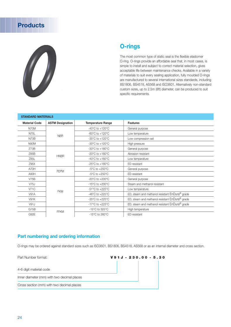
O-rings
The most common type of static seal is the flexible elastomer O-ring. O-rings provide an affordable seal that, in most cases, issimple to install and subject to correct material selection, givesacceptable life between maintenance checks. Available in a varietyof materials to suit every sealing application, fully moulded O-ringsare manufactured to several international sizes standards, includingBS1806, BS4518, AS568 and ISO3601. Alternatively non-standardcustom sizes, up to 2.5m (8ft) diameter, can be produced to suitspecific requirements.

25
Products
X-rings (4-lobe seals)
X-rings can be used in both reciprocating and rotary locations. Theyare typically specified at lower pressures (up to 5 MPa or 725 psi)and temperatures. Often installed into a narrower groove than an O-ring, the square envelope prevents rolling and spiral failure inreciprocating applications. X-rings offer low friction as they trapmedia between the lobe to form a lubricant reservoir. High sealingefficiency is achieved as the mould part line is not coincident withthe primary sealing faces.
In low pressure applications friction can be further minimized by selection of low modulus materials and specification of a cross section which isas low as possible. In high pressure applications friction can be minimised by selecting a harder grade of material with low coefficient of friction.
Groove dimensions, inspection drawings and 3D CAD files may bedownloaded using the PPELive on-line service, see page 7.
Part numbering and ordering information
X-rings may be ordered as an internal diameter and cross section.
STANDARD MATERIALS
Material Code ASTM Designation Temperature Range Features
N70M -40°C to +120°C General purpose
N75L NBR -60°C to +120°C Low temperature
N73B -35°C to +120°C Low compression set
Z73BHNBR
-30°C to +180°C General purpose
Z85B -20°C to +180°C Abrasion resistant
A70H FEPM -5°C to +250°C General purpose
V75B -20°C to +200°C General purpose
V75J FKM -15°C to +200°C Steam and methanol resistant
V71C -51°C to +225°C Low temperature
Part Number format: V 7 5 J - 4 L - 1 0 9 . 0 0 - 5 . 3 0
4-6 digit material code
Profile 4L
Inner diameter (mm) with two decimal places
Cross section (mm) with two decimal places

26
Back-up Rings
Under extreme pressures elastomers may extrude out of the clearance gap on the low pressure side of a groove. This visco-elastic failure modeis dependent upon differential pressure, size of gap, material and operating temperature. High modulus elastomer materials can offer increasedextrusion resistance. However, above 10 MPa (1,500 psi), it is common practice to widen the groove and add either one or two back-up ringsadjacent to the O-ring. Back-up rings are typically made of plastic materials that do not suffer the same visco-elastic extrusion mechanism aselastomers.
For intermediate pressure low modulus plastics, such as PTFE are used. At extremely high pressures higher modulus plastics such as PEEKare used together with higher modulus elastomers.
Applications with unidirectional pressure require just one back-up; however it is recommended that two back-ups are used to help ensurecorrect assembly.
Back-ups may be used in both static and dynamic applications.
O-ring extrusion Energized O-ring with back-upNon-energized O-ring with back-up
STANDARD MATERIALS
Material Code Temperature Range ASTM Designation Description
T99W -200°C to +260°C Virgin
T99C -200°C to +260°C 25% Carbon
T99GM -200°C to +260°C PTFE 15% Glass 5% MoS2
T99B -200°C to +260°C 40% Bronze
T99E -200°C to +260°C 10% Ekonol®
T55B -200°C to +250°C Virgin
T56B -200°C to +240°CPEEK
Bearing grade
T57B -200°C to +240°C Glass filled
T58B -200°C to +240°C Carbon filled
Products

27
Products
B1 B2 B3 B4 B5
Back-up Ring Profiles
ExampleA virgin PTFE scarf cut back-up to be used with a static AS568-214 O-ring in an AS4716 rod groove would be referenced as: T99W B2SR A214
Groove dimensions, inspection drawings and 3D CAD files may be downloaded using the PPELive on-line service, see page 7.
Non-standard back-up rings may also be ordered against ISO3601-4 dimensions, or by providing the groove size into which the back-up is to be installed.
† AS4716 piston and rod grooves correspond to the AS568 O-ring standard
† MIL-G-5514 piston and rod groove should beselected for MS28774 & MS27595 back-ups.
Part Number format: T 9 9 G M B 2 S P M 2 0 9 3 5 7
4-6 digit material code
Profile B1, B2, B3, B4, B5
Static (S), Hydraulic (H), Pneumatic (P)(H & P only applicable to ISO3601 & BS4518 grooves)
Rod Groove (R), Piston Groove (P)
Groove standardISO3601(I), AS4716(A)†, MIL-G-5514 (S)†, BS1806(B), BS4518 (M)
Dash Size Reference (3 digits / 4-2 digits for BS4518)
Part numbering and ordering information
28
T-seals
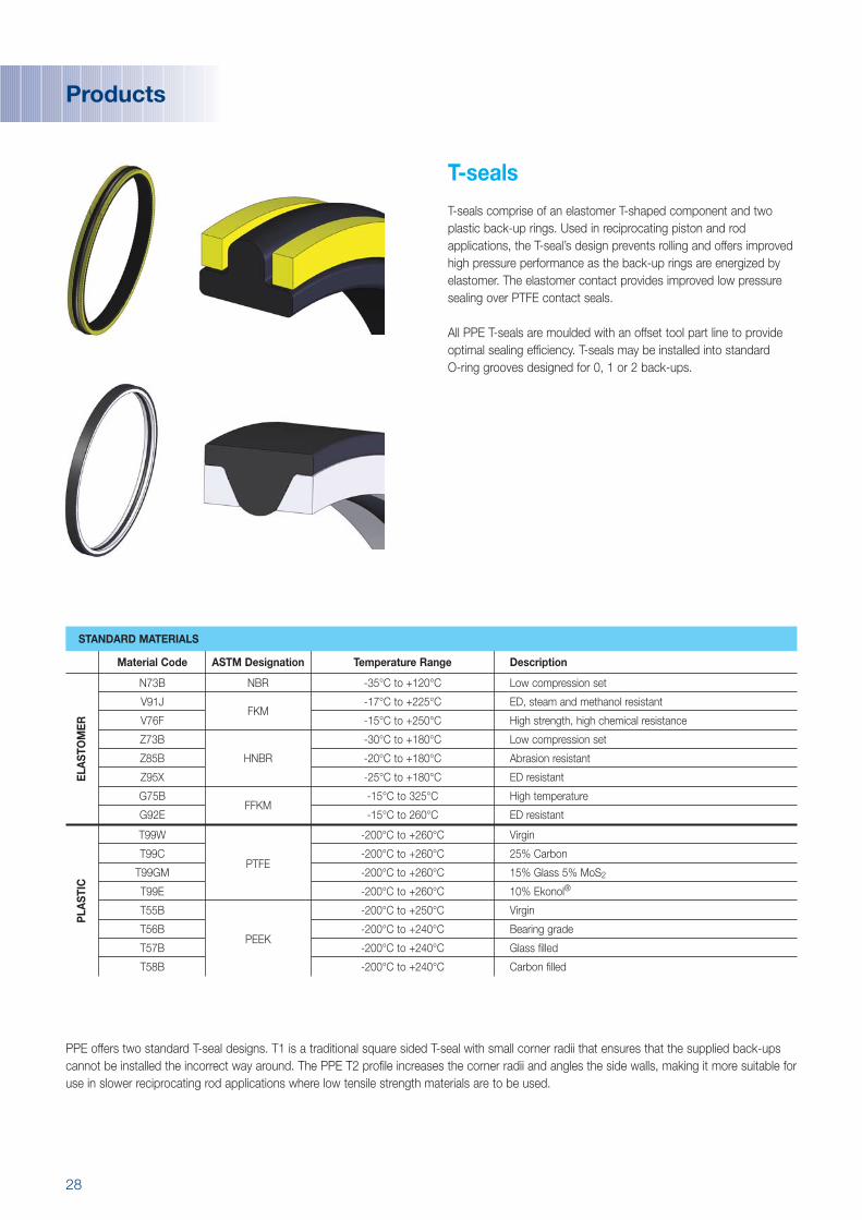
T-seals comprise of an elastomer T-shaped component and twoplastic back-up rings. Used in reciprocating piston and rodapplications, the T-seal’s design prevents rolling and offers improvedhigh pressure performance as the back-up rings are energized byelastomer. The elastomer contact provides improved low pressuresealing over PTFE contact seals.
All PPE T-seals are moulded with an offset tool part line to provideoptimal sealing efficiency. T-seals may be installed into standard O-ring grooves designed for 0, 1 or 2 back-ups.
PPE offers two standard T-seal designs. T1 is a traditional square sided T-seal with small corner radii that ensures that the supplied back-upscannot be installed the incorrect way around. The PPE T2 profile increases the corner radii and angles the side walls, making it more suitable foruse in slower reciprocating rod applications where low tensile strength materials are to be used.
STANDARD MATERIALS
Material Code ASTM Designation Temperature Range Description
N73B NBR -35°C to +120°C Low compression set
V91JFKM
-17°C to +225°C ED, steam and methanol resistant
V76F -15°C to +250°C High strength, high chemical resistance
Z73B -30°C to +180°C Low compression set
Z85B HNBR -20°C to +180°C Abrasion resistant
Z95X -25°C to +180°C ED resistant
G75BFFKM
-15°C to 325°C High temperature
G92E -15°C to 260°C ED resistant
ELA
STO
MER
T99W -200°C to +260°C Virgin
T99CPTFE
-200°C to +260°C 25% Carbon
T99GM -200°C to +260°C 15% Glass 5% MoS2
T99E -200°C to +260°C 10% Ekonol®
T55B -200°C to +250°C Virgin
T56BPEEK
-200°C to +240°C Bearing grade
T57B -200°C to +240°C Glass filled
T58B -200°C to +240°C Carbon filled
PLA
STIC
Products
29
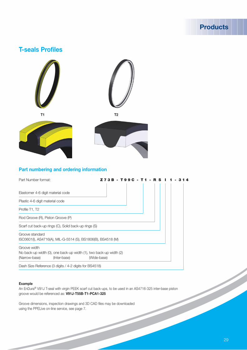
ExampleAn EnDura® V91J T-seal with virgin PEEK scarf cut back-ups, to be used in an AS4716-325 inter-base piston groove would be referenced as: V91J-T55B-T1-PCA1-325
Groove dimensions, inspection drawings and 3D CAD files may be downloaded using the PPELive on-line service, see page 7.
Part Number format: Z 7 3 B - T 9 9 C - T 1 - R S I 1 - 3 1 4
Elastomer 4-6 digit material code
Plastic 4-6 digit material code
Profile T1, T2
Rod Groove (R), Piston Groove (P)
Scarf cut back-up rings (C), Solid back-up rings (S)
Groove standardISO3601(I), AS4716(A), MIL-G-5514 (S), BS1806(B), BS4518 (M)
Groove widthNo back-up width (0), one back-up width (1), two back-up width (2)(Narrow-base) (Inter-base) (Wide-base)
Dash Size Reference (3 digits / 4-2 digits for BS4518)
T1 T2
Products
Part numbering and ordering information
T-seals Profiles

30
L-seals
L-seals comprise of an elastomer L-shaped component and aplastic back-up ring. L-seals are used statically with unidirectionalpressure and offer improved high pressure performance as theback-up rings are energized by elastomer. The elastomer contactprovides improved low pressure sealing over PTFE contact seals. L-seals are may be installed into standard O-ring grooves designedfor 0, 1 or 2 back-ups.
STANDARD MATERIALS
Material Code ASTM Designation Temperature Range Description
N75LNBR
-60°C to +135°C Low temperature
N73B -35°C to +120°C Low compression set
V91J -17°C to +225°C ED, steam and methanol resistant
V91A -46°C to +225°C Low temperature, ED, steam and methanol resistant
V75J FKM -15°C to +200°C Steam and methanol resistant
V74C -18°C to +225°C Low compression set
V71C -51°C to +225°C Low temperature
Z73B -30°C to +180°C Low compression set
Z85B HNBR -20°C to +180°C Abrasion resistant
Z95X -25°C to +180°C ED resistant
A70H FEPM -5°C to +250°C General purpose
G75BFFKM
-15°C to 325°C High temperature
G92E -15°C to 260°C ED resistant
ELA
STO
MER
T99W PTFE -200°C to +260°C Virgin
T55B PEEK -200°C to +240°C VirginPLAS
TIC
Products

31
ExampleAn EnDura® Z95X L-seal with virgin PTFE scarf cut back-ups, to be used in a BS1806-222 narrow-base piston groove would be referenced as: Z95X-T99W-L1-PCB0-222
Groove dimensions, inspection drawings and 3D CAD files may be downloaded using the PPELive on-line service, see page 7.
Part Number format: A 7 0 H - T 9 9 W - L 1 - P C A 1 - 4 5 8
Elastomer 4-6 digit material code
Plastic 4-6 digit material code
Profile L1
Rod Groove (R), Piston Groove (P)
Scarf cut back-up rings (C), Solid back-up rings (S)
Groove standardISO3601(I), AS4716(A), MIL-G-5514 (S), BS1806(B), BS4518 (M)
Groove widthNo back-up width (0), one back-up width (1), two back-up width (2)(Narrow-base) (Inter-base) (Wide-base)
Dash Size Reference (3 digits / 4-2 digits for BS4518)
Products
Part numbering and ordering information
L-seals Profile
L1

32
Energised Lip Seals
Energised lip seals comprise a high modulus, U-shaped,symmetrical, elastomer jacket and a low modulus O-ring energizer,available from PPE in two profiles; U1 and U2. Used in reciprocatingdynamic applications with unidirectional pressure, such as rod seals,they provide a versatile, multi-purpose sealing solution for use inhigh and low pressure applications.
The U1 profile includes scraper lips, to stop the ingress of debris inrotary, rod and piston geometries.
The U2 profile positions the seal contact point above the principleaxis of the energizing O-ring to maximize seal contact force andsealing efficiency.
The U2 profile may also be utilized in highly abrasive rotaryapplications where PTFE contact seals are not suitable, such asmud motors. This profile forms a positive contact seal, rather than a hydro-dynamic seal, often used in this type of application, leadingto longer oil reservoir retention and increased life.
STANDARD MATERIALS
Material Code ASTM Designation Temperature Range Description
Q48TC AU -37°C to +110°C Hydrolysis resistant
Z95X -25°C to +180°C ED resistant
Z85TM HNBR -20°C to +150°C Machined grade
Z85B -20°C to +180°C Abrasion resistant
V91J FKM
-17°C to +225°C ED resistant
V85TM -20°C to +220°C Machined grade
JAC
KET
N75L -60°C to +135°C Low temperature
N70M NBR -40°C to +120°C General purpose
N73B -35°C to +120°C Low compression set
Z70BHNBR
-30°C to +180°C General purpose
Z85L -40°C to +160°C Low temperature
A70H FEPM -5°C to +250°C General purpose
V75B -20°C to +200°C General purpose
V75J FKM -15°C to +200°C Steam and methanol resistant
V71C -51°C to +250°C Low temperature
ENER
GIS
ER
Products

33
ExampleAn U2 profile seal with a Z85TM jacket and N70A energiser, to be used in a 1/4” depth, 0.413” wide and 1” inner diameter groove would be referenced as: Z85TM-N70M-U2-250-413-1000
Groove dimensions, inspection drawings and 3D CAD files may be downloaded using the PPELive on-line service, see page 7.Non standard dimensions are available upon request.
Part Number format: V 8 5 T M - V 7 5 B - U 1 - 1 8 7 - 2 0 6 - 1 0 0 0
Jacket 4-6 digit material code
Energiser 4-6 digit material code
Profile U1, U2
Groove depth (Nominal radial cross section in inches x 1000)
Groove width (Nominal groove width in inches x 1000)
Nominal inner diameter of seal groove in inches x 1000
Products
U2U1
STANDARD CROSS SECTIONS
Nominal Gland Depth Nominal Groove Depth (Inches) U1 Groove width U2 Groove width
1/8 0.125 0.138 0.2753/16 0.187 0.206 0.3431/4 0.250 0.275 0.4135/16 0.312 0.343 0.5503/8 0.375 0.413 0.688
Part numbering and ordering information
Lip Seals Profiles

34
Cap Seals (heavy duty)
Suitable for use on piston and rod bi-directional sealing applications,heavy duty cap seals consist of an elastomer O-ring and a PTFEcap. The elastomer is used to transmit system pressure to energisethe cap which provides improved wear resistance, less friction andanti-extrusion properties.
The heavy duty (CH) profile cap seal offers long life, low wear, highsurface speed (up to 4m/s), high pressure resistance (up to 40MPaor 5800psi) and maintains the differential pressure needed foroperation. However cap seals are regarded as a wet seal as theytypically allow an acceptable level of fluid transfer across the cap.
The CH cap seal is designed to allow retro-fitting into non-PPEgrooves for seals of similar design.
STANDARD MATERIALS
Material Code ASTM Designation Temperature Range Description
N75L -60°C to +135°C Low temperature
N70M NBR -40°C to +120°C General purpose
N73B -35°C to +120°C Low compression set
Z70BHNBR
-30°C to +180°C General purpose
Z75L -40°C to +160°C Low temperature
A70H FEPM -5°C to +250°C General purpose
V75B -20°C to +200°C General purpose
V75J FKM -15°C to +200°C Steam and methanol resistant
V71C -51°C to +250°C Low temperature
ELA
STO
MER
T99W -200°C to +260°C Virgin
T99C -200°C to +260°C 25% Carbon
T99XPTFE
-200°C to +260°C 15% Graphite
T99B -200°C to +260°C 40% Bronze
T99GM -200°C to +260°C PTFE - 15% Glass 5% MoS2
T99E -200°C to +260°C PTFE - 10% Ekonol
CA
P
Products
35
Products
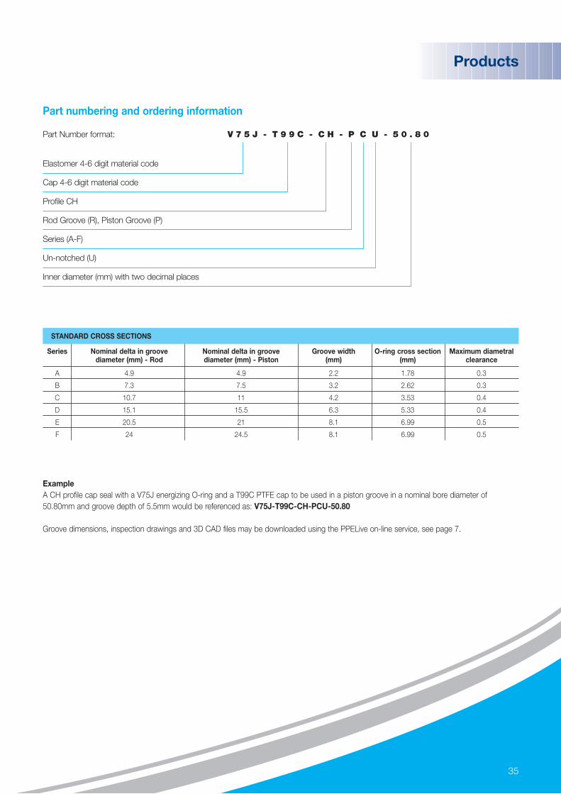
ExampleA CH profile cap seal with a V75J energizing O-ring and a T99C PTFE cap to be used in a piston groove in a nominal bore diameter of50.80mm and groove depth of 5.5mm would be referenced as: V75J-T99C-CH-PCU-50.80
Groove dimensions, inspection drawings and 3D CAD files may be downloaded using the PPELive on-line service, see page 7.
Part Number format: V 7 5 J - T 9 9 C - C H - P C U - 5 0 . 8 0
Elastomer 4-6 digit material code
Cap 4-6 digit material code
Profile CH
Rod Groove (R), Piston Groove (P)
Series (A-F)
Un-notched (U)
Inner diameter (mm) with two decimal places
STANDARD CROSS SECTIONS
Series Nominal delta in groove Nominal delta in groove Groove width O-ring cross section Maximum diametral diameter (mm) - Rod diameter (mm) - Piston (mm) (mm) clearance
A 4.9 4.9 2.2 1.78 0.3
B 7.3 7.5 3.2 2.62 0.3
C 10.7 11 4.2 3.53 0.4
D 15.1 15.5 6.3 5.33 0.4
E 20.5 21 8.1 6.99 0.5
F 24 24.5 8.1 6.99 0.5
Part numbering and ordering information

36
Cap Seals (low profile)
Low profile cap seals comprise a standard elastomer O-ringenergiser and a shaped PTFE cap which conforms to the O-ring.This profile prevents spiralling and offers improved wear resistance in light to medium duty applications. The elastomer is used totransmit system pressure to energise the cap which provides, lessfriction and anti-extrusion properties.
The low profile (CL) seal is designed to allow retro-fitting intoBS1806, MIL-G-5514 and AS4716 grooves.
STANDARD MATERIALS
Material Code ASTM Designation Temperature Range Description
N75L -60°C to +135°C Low temperature
N70M NBR -40°C to +120°C General purpose
N73B -35°C to +120°C Low compression set
Z70BHNBR
-30°C to +180°C General purpose
Z75L -40°C to +160°C Low temperature
A70H FEPM -5°C to +250°C General purpose
V75B -20°C to +200°C General purpose
V75J FKM -15°C to +200°C Steam and methanol resistant
V71C -51°C to +250°C Low temperature
ELA
STO
MER
T99W -200°C to +260°C Virgin
T99C -200°C to +260°C 25% Carbon
T99XPTFE
-200°C to +260°C 15% Graphite
T99B -200°C to +260°C 40% Bronze
T99GM -200°C to +260°C 15% Glass 5% MoS2
T99E -200°C to +260°C 10% Ekonol
CA
P
Products
37
Products
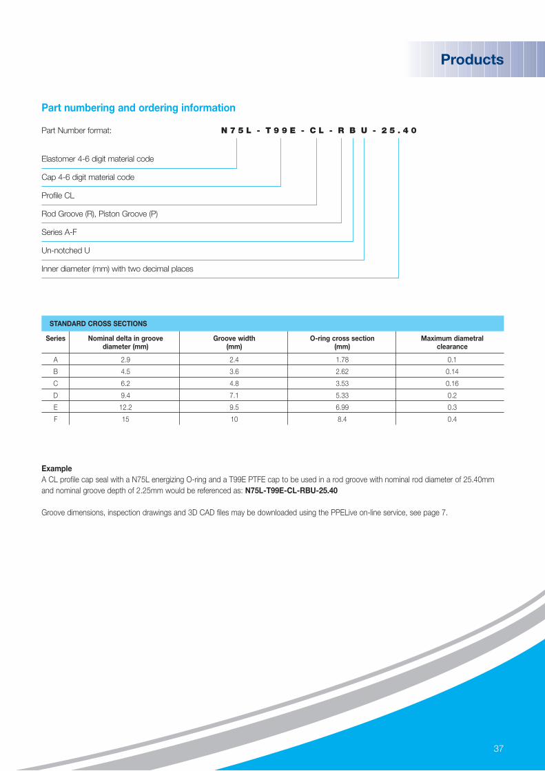
ExampleA CL profile cap seal with a N75L energizing O-ring and a T99E PTFE cap to be used in a rod groove with nominal rod diameter of 25.40mmand nominal groove depth of 2.25mm would be referenced as: N75L-T99E-CL-RBU-25.40
Groove dimensions, inspection drawings and 3D CAD files may be downloaded using the PPELive on-line service, see page 7.
Part Number format: N 7 5 L - T 9 9 E - C L - R B U - 2 5 . 4 0
Elastomer 4-6 digit material code
Cap 4-6 digit material code
Profile CL
Rod Groove (R), Piston Groove (P)
Series A-F
Un-notched U
Inner diameter (mm) with two decimal places
STANDARD CROSS SECTIONS
Series Nominal delta in groove Groove width O-ring cross section Maximum diametral diameter (mm) (mm) (mm) clearance
A 2.9 2.4 1.78 0.1
B 4.5 3.6 2.62 0.14
C 6.2 4.8 3.53 0.16
D 9.4 7.1 5.33 0.2
E 12.2 9.5 6.99 0.3
F 15 10 8.4 0.4
Part numbering and ordering information

38
Cap Seals (Venting)
Suitable for use on piston and rod dynamic sealing applications withuni-directional pressure venting, cap seals consist of an elastomerO-ring which energises a ‘P’ shaped profile PTFE stepped seal. The elastomer is used to transmit system pressure to energise thecap which provides improved wear resistance, low friction and anti-extrusion properties. The venting feature prevents the build upof trapped pressure in tandem sealing systems, which couldotherwise result in high wear and system locking.
The venting (CV) profile cap seal offers long life, low wear, highsurface speed (up to 15m/s) and high pressure resistance (up to 80MPa or 11,600 psi).
CV cap seals are designed to allow retro-fitting into ISO7425-2grooves typically used for seals of similar design.
STANDARD MATERIALS
Material Code ASTM Designation Temperature Range Description
N75L -60°C to +135°C Low temperature
N70M NBR -40°C to +120°C General purpose
N73B -35°C to +120°C Low compression set
Z70BHNBR
-30°C to +180°C General purpose
Z75L -40°C to +160°C Low temperature
A70H FEPM -5°C to +250°C General purpose
V75B -20°C to +200°C General purpose
V75J FKM -15°C to +200°C Steam and methanol resistant
V71C -51°C to +250°C Low temperature
ELA
STO
MER
T99W -200°C to +260°C Virgin
T99C -200°C to +260°C 25% Carbon
T99XPTFE
-200°C to +260°C 15% Graphite
T99B -200°C to +260°C 40% Bronze
T99GM -200°C to +260°C 15% Glass 5% MoS2
T99E -200°C to +260°C 10% Ekonol
CA
P
Products

39
Products
ExampleA CV profile cap seal with a V75B energizing O-ring and a T99B PTFE cap to be used in a rod groove with nominal rod diameter of 88.90mm and groove depth of 7.55mm would be referenced as: V75B-T99B-CV-RDU-88.90
Groove dimensions, inspection drawings and 3D CAD files may be downloaded using the PPELive on-line service, see page 7.
Part Number format: V 7 5 B - T 9 9 B - C V - R D U - 8 8 . 9 0
Elastomer 4-6 digit material code
Cap 4-6 digit material code
Profile CV
Rod Groove (R), Piston Groove (P)
Series A-F
Un-notched U
Inner diameter (mm) with two decimal places
Part numbering and ordering information
STANDARD CROSS SECTIONS
Series Nominal delta in groove Nominal groove depth Groove width O-ring cross section Maximum diametral diameter (mm) (mm) (mm) (mm) clearance
A 4.9 2.45 2.2 1.78 0.3
B 7.3 3.65 3.2 2.62 0.3
C 10.7 5.35 4.2 3.53 0.4
D 15.1 7.55 6.3 5.33 0.4
E 20.5 10.25 8.1 6.99 0.5
F 24 12 8.1 6.99 0.5

40
Wiper Seals
An important element of any fluid power sealing system are wiperseals which prevent contaminants such as moisture, dust and debrisentering the system and causing damage to metalwork and othersealing components. The snap-in configuration allows the W1 wiperseal to be fitted in many existing rod seal wiper grooves.
STANDARD MATERIALS
Material Code ASTM Designation Temperature Range Description
N90M NBR -30°C to +120°C General purpose
Z85BHNBR
-20°C to +180°C Abrasion resistant
Z85TM -20°C to +150°C Machined grade
V85TM FKM -20°C to +220°C Machined grade
STANDARD CROSS SECTIONS
Series Nominal groove depth (mm) Groove width (mm)
A 3.3 2.4
B 4.4 3.6
C 6.3 4.8
ExampleA Z85TM, W1 wiper to be used in a rod groove with nominal rod diameter of 60.00mm and nominal groove depth of 4.4mm would bereferenced as: Z85TM-W1-B-60.00
Groove dimensions, inspection drawings and 3D CAD files may be downloaded using the PPELive on-line service, see page 7.
Part Number format: Z 8 5 B - W 1 - A - 5 2 . 5 0
Elastomer 4-6 digit material code
Profile W1
Series A-C
Inner diameter (mm) with two decimal places
Part numbering and ordering information
Products

41
High pressure closure lip seals
PPE has extensive expertise in the design of lip seals for highpressure enclosures and can offer custom designs and materialselection to meet the specific requirements of your application. Sealscan be designed to customer requirements to meet ASA ratings upto 2500 lbf with seal diameters up to 72 inches (1.8 metres) in arange of materials optimized for oil and gas applications.
Typical Seal Designs
Products
Low pressure seal High pressure – integrated spring High pressure – integrated back-up
Finite element analysis of high pressure seal with back-up

42
Wear Rings / Bearings
Available in a variety of PTFE and PEEK blends, wear rings provide low friction bearings for use in rod and piston sealing applications.Designed to fit into ISO 10766 groove dimensions, the PPE range of PTFE and PEEK bearings is available with either a diagonal or square cutto meet the requirements of most oilfield applications.
It is common practice to increase the radial clearance when a bearing is introduced into the system. Contact PPE / AOS for seal / bearingsystem design assistance.
STANDARD MATERIALS
Material Code ASTM Designation Temperature Range Description
T99W -200°C to +260°C Virgin
T99C -200°C to +260°C 25% Carbon
T99XPTFE
-200°C to +260°C 15% Graphite
T99GM -200°C to +260°C 15% Glass 5% MoS2
T99E -200°C to +260°C 10% Ekonol
T99B -200°C to +260°C 40% Bronze
T55B -200°C to +250°C Virgin
T56BPEEK
-200°C to +240°C Bearing grade
T57B -200°C to +240°C Glass filled
T58B -200°C to +240°C Carbon filled
See product datasheets for specific material properties.
J2 (Piston) / J4 (Rod)J1 (Piston) / J3 (Rod)
Products
43
STANDARD CROSS SECTIONS
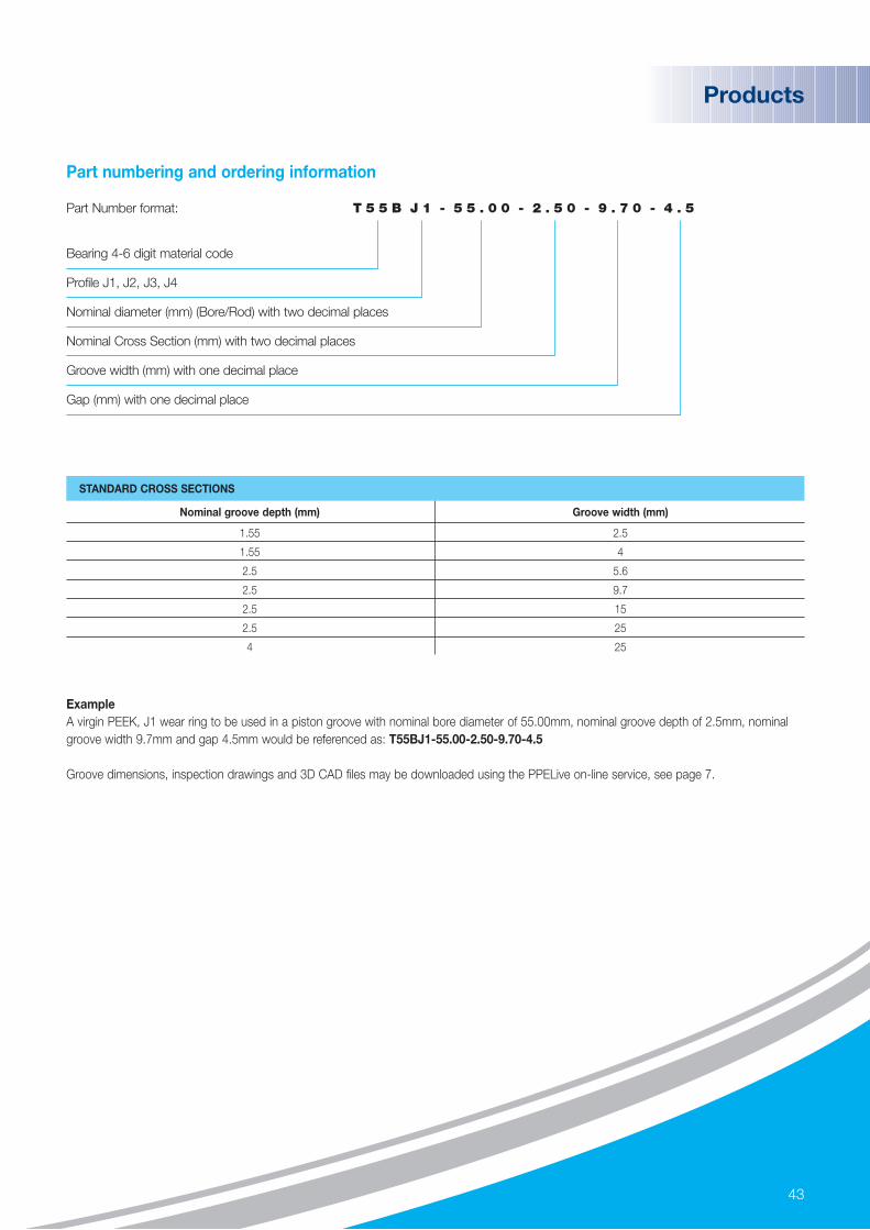
Nominal groove depth (mm) Groove width (mm)
1.55 2.5
1.55 4
2.5 5.6
2.5 9.7
2.5 15
2.5 25
4 25
ExampleA virgin PEEK, J1 wear ring to be used in a piston groove with nominal bore diameter of 55.00mm, nominal groove depth of 2.5mm, nominalgroove width 9.7mm and gap 4.5mm would be referenced as: T55BJ1-55.00-2.50-9.70-4.5
Groove dimensions, inspection drawings and 3D CAD files may be downloaded using the PPELive on-line service, see page 7.
Part Number format: T 5 5 B J 1 - 5 5 . 0 0 - 2 . 5 0 - 9 . 7 0 - 4 . 5
Bearing 4-6 digit material code
Profile J1, J2, J3, J4
Nominal diameter (mm) (Bore/Rod) with two decimal places
Nominal Cross Section (mm) with two decimal places
Groove width (mm) with one decimal place
Gap (mm) with one decimal place
Part numbering and ordering information
Products
44
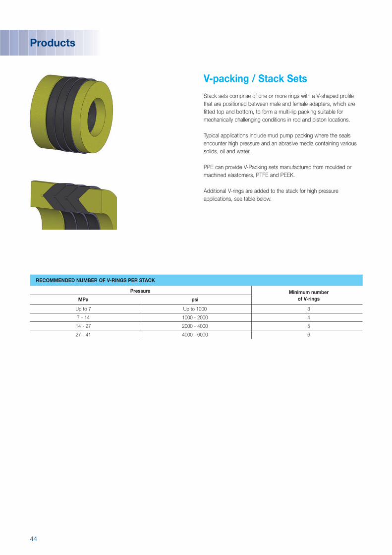
V-packing / Stack Sets
Stack sets comprise of one or more rings with a V-shaped profilethat are positioned between male and female adapters, which arefitted top and bottom, to form a multi-lip packing suitable formechanically challenging conditions in rod and piston locations.
Typical applications include mud pump packing where the sealsencounter high pressure and an abrasive media containing varioussolids, oil and water.
PPE can provide V-Packing sets manufactured from moulded ormachined elastomers, PTFE and PEEK.
Additional V-rings are added to the stack for high pressureapplications, see table below.
RECOMMENDED NUMBER OF V-RINGS PER STACK
Pressure Minimum numberMPa psi of V-rings
Up to 7 Up to 1000 3
7 - 14 1000 - 2000 4
14 - 27 2000 - 4000 5
27 - 41 4000 - 6000 6
Products

45
Products
Packer elements
High performance elastomerpacker elements are a vitalcomponent of completionhardware. Used to provide aseal between the outside ofthe tubing and the inside ofthe casing, liner, or wellborewall, the packer isolates andprotects the annulus,preventing reservoir fluids from flowing up the full lengthof the casing and damaging it. PPE are experts in themanufacture of homogeneous,large cross section parts withlow porosity to ensureexcellent performance underhigh mechanical strain. PPEcan post machine under-cutsinto the inner diameter of apacker, or for ease ofassembly, PPE can mould in-situ metallic components.
Blow-out Preventer Ram Blocks
Ram blocks areused in pairs inblowout preventers,located at thewellhead. Theirfunction is to clampshut to seal off thewellbore, preventingthe escape ofpressure in the event of an unwanted blow-out of fluid or gas.Manufactured from high performance elastomer and steel andavailable in a range of sizes, ram blocks seal the hole withoutsevering the drillstring allowing pressure control to be regained inside the well.
Pigs
Pipeline cleaning is animportant component of any long-term integrity andmaintenance program.Elastomer cleaning pigs aredesigned to remove internaldebris from pipelines whilstthey are propelled along bythe pressure of the product.Pigs may incorporate amagnet to assist withlocation identification. Sealing pigs are also used to provide a sealbetween two products within the pipeline or sweep liquids from the line.
Wiper darts
Wiper darts are designed to displace well fluids and cement and act as a mechanical barrier to avoid the contamination of the cement with mud inside drill pipe and liner.
Bonded Port Seals
PPE supply bonded seal designs to allow port transitions at high pressure.
Dovetail Packing Element
46
Custom components
PPE and AOS offer a complete component design service with the ability to design and manufacture custom parts and bespoke engineeredcomponents to customer specifications.
Problem-solving is central to our culture, providing customers with optimal design solutions. Using the latest elastomer materials andmanufacturing techniques, combined with many years experience, we can produce custom shapes and profiles to meet any requirements.
In developing custom parts we work closely with our customers to develop solutions that last longer, require less maintenance and deliver thelowest cost of ownership.
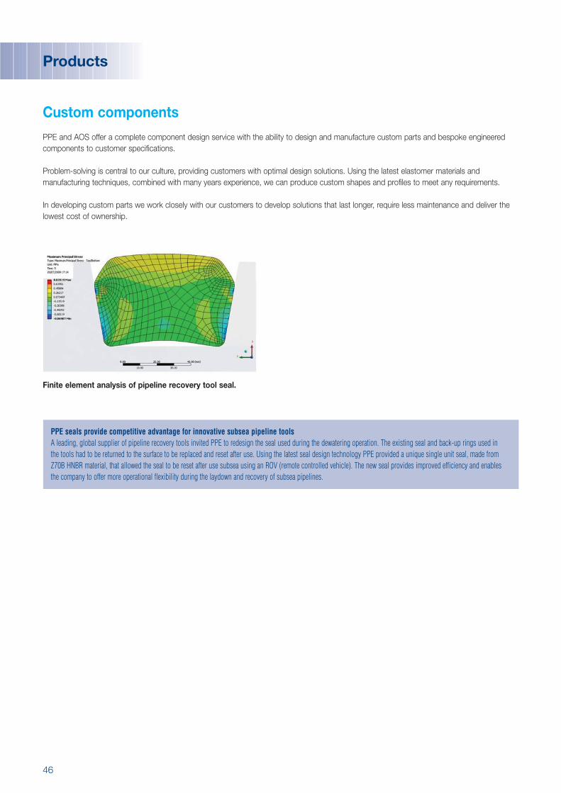
Finite element analysis of pipeline recovery tool seal.
Products
PPE seals provide competitive advantage for innovative subsea pipeline toolsA leading, global supplier of pipeline recovery tools invited PPE to redesign the seal used during the dewatering operation. The existing seal and back-up rings used in the tools had to be returned to the surface to be replaced and reset after use. Using the latest seal design technology PPE provided a unique single unit seal, made fromZ70B HNBR material, that allowed the seal to be reset after use subsea using an ROV (remote controlled vehicle). The new seal provides improved efficiency and enablesthe company to offer more operational flexibility during the laydown and recovery of subsea pipelines.

47
Product Selection Guide by Application
Products
Filters o o o o
Manifolds o o o o o o o
Swivels o o o o o o o o o o
Actuators o o o o o o o o o o o o o o o o o
MWDs o o o o o o o
Cementing equipment o o
Mud pumps o o o o o
Drill bits o o o
Actuators o o o o o o o o o o o o o o o
Fishing Tools o o o o o o o o o o
Logging equipment o o o o o o o o o o o
Perforating equipment o o o o o o
Line packers & hangers o o o o o o
Christmas trees o o o o o o o o o o
Sampling o o o o o o o o o
Wellhead o o o o o o o o o
Chokes & valves o o o o o o o o o
Blow out preventors (BOPs) o o o
Enhanced oil recovery o o o o o o o o o o o o o o
Flow management o o o o o o o
Pumps & compressors o o o o o o o o o
Power gen-sets o o o o o
Pipelines o o
Risers o o o o
o o o o o
O-r
ings
Bac
k-up
Rin
gs
T-se
als
L-se
als
V-st
ack
sets
X-r
ings
(4-l
obe
seal
s)
Lip
seal
s
Cap
sea
l - H
D
Cap
sea
l - L
P
Cap
sea
l - s
tepp
ed
Wip
er s
eals
Sprin
g se
als
BO
Ps
Pac
kers
Wea
r rin
gs (b
earin
gs)
Cus
tom
com
pone
nts
EPD
M
NB
R
HN
BR
FKM
FEP
M
FFK
M (P
erla
st®)
PEE
K
PTF
E
TPU
GEN
ERA
L
APPLICATION PRODUCTS / PROFILES MATERIALS
EXP
LOR
ATIO
N&
DR
ILLI
NG
TEST
ING
&
CO
MP
LETI
ON
PR
OD
UC
TIO
N /
SU
BSE
A
Carbon (CO2) capture / storage
Precision Polymer Engineering Limited
Greenbank Road Blackburn BB1 3EA England
Tel: +44 (0) 1254 295400
Fax: +44 (0) 1254 680182
Email: [email protected]
www.prepol.com
Perlast Limited
1754 Technology Drive, Suite 244San JoseCA 95110USA
Tel: +1 408 441 2043Fax: +1 408 441 1042Email: [email protected]
Aberdeen O-rings & Seals Limited
Block 1, Unit 8 Souterhead Road Industrial EstateAltens, AberdeenAB12 3LFScotland
Tel: +44 (0) 1224 877844
Fax: +44 (0) 1224 877866
Email: [email protected]
www.aberdeenseals.co.uk
11/09
Important note: This document was compiled in Sept 2009. Subsequent changes may affect the validity of information hereincontained. While every effort is made to ensure accuracy, noresponsibility can be taken for incorrect information.
PPE makes no warranty, expressed or implied, that parts will perform satisfactorily in the customer’s application. It is the customer’s responsibility to evaluate parts prior to use, especially in applications where their failure may result in injury and/or damage.
© Precision Polymer Engineering Ltd. All rights reserved.
Hig
h Perfo
rmance S
ealing S
olutio
ns for the Oil & G
as industry
![Crude Assay Report · 15 Vacuum Gas Oil Cuts - Gas Oil [325-370°C] 15 16 Vacuum Gas Oil Cuts - Gas Oil 1[370 - 540°C] 16 17 Vacuum Gas Oil Cuts - Heavy Vacuum Gas Oil [370 - 548°C]](https://static.fdocuments.us/doc/165x107/5e68681c2598ff04995c67bc/crude-assay-report-15-vacuum-gas-oil-cuts-gas-oil-325-370c-15-16-vacuum-gas.jpg)