Fish Passage Planning and Design - James Cook University · Culvert Fishway Planning and Design...
70
Culvert Fishway Planning and Design Guidelines Part F – Baffle Fishways for Box Culverts Ross Kapitzke James Cook University School of Engineering and Physical Sciences April 2010 – VER2.0 Fish Passage Planning and Design
Transcript of Fish Passage Planning and Design - James Cook University · Culvert Fishway Planning and Design...

Culvert Fishway Planning and Design GuidelinesPart F – Baffle Fishways for Box Culverts
Ross Kapitzke James Cook University School of Engineering and Physical Sciences
April 2010 – VER2.0
Fish Passage Planning and Design

VER2.0 -/04/10
School of Engineering and Physical Sciences • Ross Kapitzke • fishways\F_baffle fishways for box culverts -/4/10
F-i
Culvert fishway guidelines: Part F – Baffle fishways for box culverts
James Cook University School of Engineering and Physical Sciences Culvert Fishway Planning and Design Guidelines Part F – Baffle Fishways for Box Culverts Contents
1 INTRODUCTION 1
2 FISH MIGRATION BARRIER PROBLEMS AT BOX CULVERTS 2
3 BAFFLE FISHWAY DESIGNS FOR BOX CULVERTS AND PIPE CULVERTS 5 3.1 Design concepts and background for baffle type culvert fishways 5 3.2 Design configuration and parameters for baffle type culvert fishways 6 3.3 General hydraulic performance characteristics of baffle type fishways 8 3.4 General fish passage characteristics of baffle type culvert fishways 9 3.5 Conveyance, sediment and maintenance characteristics of baffle type fishways 11
4 OFFSET BAFFLE FISHWAY DESIGN FOR BOX CULVERTS 13 4.1 Design concept and configuration for offset baffle fishway 13 4.2 Hydraulic performance characteristics of offset baffle fishway 16 4.3 Fish passage characteristics of offset baffle fishway 17 4.4 Conveyance, sediment and maintenance characteristics of offset baffle fishway 19
5 CORNER “EL” BAFFLE FISHWAY DESIGN FOR BOX CULVERTS 21 5.1 Design concept and configuration for corner “EL” baffle fishway 21 5.2 Hydraulic performance characteristics of corner “EL” baffle fishway 24 5.3 Fish passage characteristics of corner “EL” baffle fishway 25 5.4 Conveyance, sediment and maintenance characteristics of “EL” baffle fishway 26
6 OVERALL SUITABILITY OF BAFFLE FISHWAY DESIGNS 28
7 BIBLIOGRAPHY 30
APPENDIX F1 – DISCOVERY DRIVE PROTOTYPE OFFSET BAFFLE FISHWAY 1
APPENDIX F2 – DISCOVERY DRIVE PROTOTYPE CORNER “EL” BAFFLE FISHWAY 2

VER2.0 -/04/10
School of Engineering and Physical Sciences • Ross Kapitzke • fishways\F_baffle fishways for box culverts -/4/10 F-1
Culvert fishway guidelines: Part F – Baffle fishways for box culverts
James Cook University School of Engineering and Physical Sciences Culvert Fishway Planning and Design Guidelines Part F – Baffle Fishways for Box Culverts
1 INTRODUCTION
Where provisions for fish passage are to be made at box culvert waterway crossings, designers, managers and scientists require information on fishway design options for box culverts, and the configuration and performance characteristics of fish passage devices such as baffle fishways.
These Guidelines Part F present the baffle fishway designs for box culverts, and aim to:
identify baffle fishway design options to suit particular hydraulic barriers to fish passage at box culverts, and describe relevant culvert fishway configurations and characteristics
outline design concepts and background, and general configuration and performance characteristics of baffle type fishways for box culvert and for pipe culverts
outline design concepts, configurations, and performance characteristics for the offset baffle fishway and the corner “EL” baffle fishway for box culverts
illustrate baffle fishway design for box culverts through the University Creek Discovery Drive and Bruce Highway Corduroy Creek to Tully case study projects
summarise findings of the field prototype and laboratory model testing of the offset baffle and corner “EL” baffle fishway designs for box culverts (Appendix F1; Appendix F2)
The information from Guidelines Part F is used in other parts of these Guidelines to:
guide the selection of fishway devices to meet fish passage requirements for box culverts (Part C – Fish Migration Barriers and Fish Passage Options for Road Crossings)
guide the design configurations for fishway facilities in box culvert waterway crossings incorporating baffle fishways (Part E – Fish Passage Design: Site Scale)
These Guidelines deal primarily with the Concept and Preliminary Design phases of planning and design procedures for road and other infrastructure projects. They apply to design of fish passage facilities to mitigate potential fish migration barrier impacts at new structures, and also to remediation measures to overcome barriers by retrofit at existing structures (Box F1.1).
Box F1.1: Baffle fishway facilities for box culverts established at the Discovery Drive crossing of University Creek in Townsville (Source: Ross Kapitzke)
Plotosid catfish moving upstream through offset baffle fishway – resting behind
perpendicular baffle (13/01/04)
Corner “EL” baffle fishway with flow nearly submerging horizontal leg – looking upstream
(-/04/06)
VER2.0 -/04/10
School of Engineering and Physical Sciences • Ross Kapitzke • fishways\F_baffle fishways for box culverts -/4/10 F-2
Culvert fishway guidelines: Part F – Baffle fishways for box culverts
2 FISH MIGRATION BARRIER PROBLEMS AT BOX CULVERTS
Box culverts are used extensively for waterway drainage crossings in Australia. This ranges from narrow track crossings of small streams using single cell culverts less than 2 m wide, 1.2 m high, and 4 m long, through to multiple carriageway road crossings of major waterways using multi-cell culverts up to 30 m wide, 4 m high, and 60 m long. A conventional design approach to waterway crossing design with a focus on drainage, transport and utility functions commonly leads to fish migration barrier problems for many box culvert structures. An alternative approach that provides for fish movement through the crossings can use baffle fishway devices in conjunction with other fishway components to overcome fish migration barriers by mitigation of impacts for new developments or remediation of barriers through retrofit at existing structures.
This chapter briefly outlines the common fish migration barrier problems at box culvert structures. Illustrations of fish migration barriers and mitigation / remediation design using baffle fishway devices are provided in this chapter and in subsequent chapters for the Discovery Drive box culvert crossing of University Creek in Townsville (Box F2.1), where the offset baffle and corner “EL” baffle prototype fishway designs have been implemented as retrofits (Kapitzke 2006b; Kapitzke 2007b), and for the Bruce Highway Corduroy Creek to Tully road project (Box F2.2), where the corner “EL” baffle fishway has been adopted for priority road-waterway crossings on the new road and existing road (Kapitzke 2006a; Kapitzke 2007a).
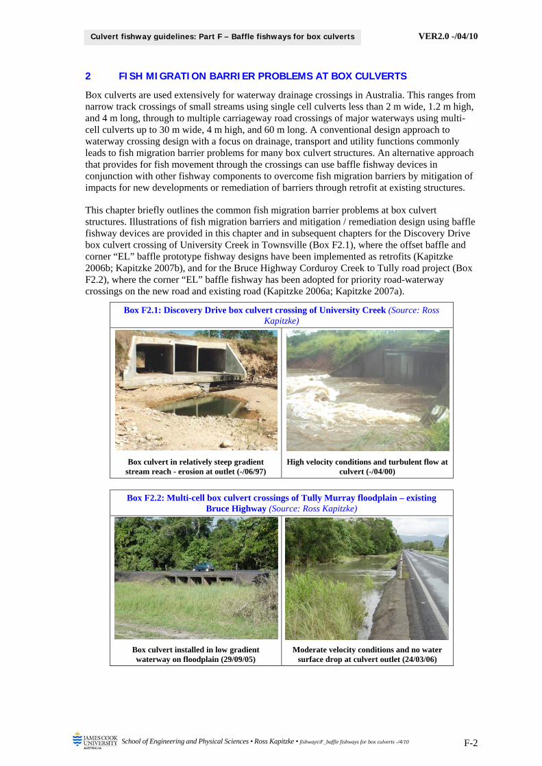
Box F2.1: Discovery Drive box culvert crossing of University Creek (Source: Ross Kapitzke)
Box culvert in relatively steep gradient stream reach - erosion at outlet (-/06/97)
High velocity conditions and turbulent flow at culvert (-/04/00)
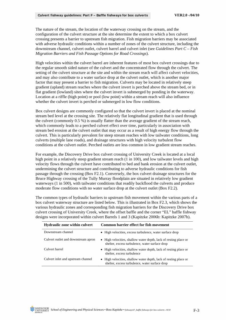
Box F2.2: Multi-cell box culvert crossings of Tully Murray floodplain – existing
Bruce Highway (Source: Ross Kapitzke)
Box culvert installed in low gradient waterway on floodplain (29/09/05)
Moderate velocity conditions and no water surface drop at culvert outlet (24/03/06)
VER2.0 -/04/10
School of Engineering and Physical Sciences • Ross Kapitzke • fishways\F_baffle fishways for box culverts -/4/10 F-3
Culvert fishway guidelines: Part F – Baffle fishways for box culverts
The nature of the stream, the location of the waterway crossing on the stream, and the configuration of the culvert structure at the site determine the extent to which a box culvert crossing presents a barrier to upstream fish migration. Fish migration barriers may be associated with adverse hydraulic conditions within a number of zones of the culvert structure, including the downstream channel, culvert outlet, culvert barrel and culvert inlet (see Guidelines Part C – Fish Migration Barriers and Fish Passage Options for Road Crossings).
High velocities within the culvert barrel are inherent features of most box culvert crossings due to the regular smooth sided nature of the culvert and the concentrated flow through the culvert. The setting of the culvert structure at the site and within the stream reach will affect culvert velocities, and may also contribute to a water surface drop at the culvert outlet, which is another major factor that may present a barrier to fish migration. Culverts may be located in relatively steep gradient (upland) stream reaches where the culvert invert is perched above the stream bed, or in flat gradient (lowland) sites where the culvert invert is submerged by ponding in the waterway. Location at a riffle (high point) or pool (low point) within a stream reach will also influence whether the culvert invert is perched or submerged in low flow conditions.
Box culvert designs are commonly configured so that the culvert invert is placed at the nominal stream bed level at the crossing site. The relatively flat longitudinal gradient that is used through the culvert (commonly 0.5 %) is usually flatter than the average gradient of the stream reach, which commonly leads to a perched culvert effect over time, particularly in association with stream bed erosion at the culvert outlet that may occur as a result of high energy flow through the culvert. This is particularly prevalent for steep stream reaches with low tailwater conditions, long culverts (multiple lane roads), and drainage structures with high velocity turbulent flow conditions at the culvert outlet. Perched outlets are less common in low gradient stream reaches.
For example, the Discovery Drive box culvert crossing of University Creek is located at a local high point in a relatively steep gradient stream reach (1 in 100), and low tailwater levels and high velocity flows through the culvert have contributed to bed and bank erosion at the culvert outlet, undermining the culvert structure and contributing to adverse hydraulic conditions for fish passage through the crossing (Box F2.1). Conversely, the box culvert drainage structures for the Bruce Highway crossing of the Tully Murray floodplain are situated in relatively low gradient waterways (1 in 500), with tailwater conditions that readily backflood the culverts and produce moderate flow conditions with no water surface drop at the culvert outlet (Box F2.2).
The common types of hydraulic barriers to upstream fish movement within the various parts of a box culvert waterway structure are listed below. This is illustrated in Box F2.3, which shows the various hydraulic zones and corresponding fish migration barriers for the Discovery Drive box culvert crossing of University Creek, where the offset baffle and the corner “EL” baffle fishway designs were incorporated within culvert Barrels 1 and 3 (Kapitzke 2006b: Kapitzke 2007b).
Hydraulic zone within culvert Common barrier effect for fish movement
Downstream channel High velocities, excess turbulence, water surface drop
Culvert outlet and downstream apron High velocities, shallow water depth, lack of resting place or shelter, excess turbulence, water surface drop
Culvert barrel High velocities, shallow water depth, lack of resting place or shelter, excess turbulence
Culvert inlet and upstream channel High velocities, shallow water depth, lack of resting place or shelter, excess turbulence, water surface drop

VER2.0 -/04/10
School of Engineering and Physical Sciences • Ross Kapitzke • fishways\F_baffle fishways for box culverts -/4/10 F-4
Culvert fishway guidelines: Part F – Baffle fishways for box culverts
Box F2.3: Hydraulic zones and fish migration barriers within Discovery Drive box culvert crossing (After: Kapitzke 2006b: Kapitzke 2007b)
Zone A: Downstream channel (subject to fluctuating tailwater – temporarily raised since 2004) 1
potential for water surface drop downstream of culvert outlet slab with low tailwater conditions in downstream reach
no existing hydraulic barriers in this Zone due to raised tailwater conditions downstream
(Photo: 16/01/04; Source: Ross Kapitzke)
Zone B: Culvert outlet and downstream apron slab
high velocities and lack of shelter at the culvert outlet and on the downstream apron
potential for shallow water depth with low tailwater conditions in downstream reach
excess turbulence in medium flow conditions and in low flow with low tailwater conditions
(Photo: with lowered tailwater condition – 24/03/97; Source: Ross Kapitzke)
Zone C: Culvert barrel
high velocities within the culvert barrel – up to 3m/s for medium flow
potential for shallow water depth with low tailwater conditions in downstream reach
regular cross section and lack of resting place along the culvert barrel
(Photo: 15/02/02; Source: Ross Kapitzke)
Zone D: Culvert inlet, upstream apron slab and channel
high velocities and lack of shelter at the culvert inlet during low and medium flows
(Photo: 27/01/06; Source: Ross Kapitzke)
1 Tailwater conditions for the Discovery Drive box culvert are subject to fluctuating downstream water levels associated with possible bed deposition or erosion at the downstream riffle control in University Creek. Control levels have built up and tailwater levels have been temporarily raised since 2004.
Culvert inlet and upstream channel
Culvert barrel
Downstream channel
Culvert outlet and apron slab
Zone D Zone C Zone B Zone A
3–Cell box culvert
Flow Low flow
Medium flow

VER2.0 -/04/10
School of Engineering and Physical Sciences • Ross Kapitzke • fishways\F_baffle fishways for box culverts -/4/10 F-5
Culvert fishway guidelines: Part F – Baffle fishways for box culverts
3 BAFFLE FISHWAY DESIGNS FOR BOX CULVERTS AND PIPE CULVERTS
Baffle type fishways are most likely to be used in the culvert barrel or on outlet apron slabs of box or pipe culvert waterway structures, and in channelised waterway sections to overcome high velocities, shallow water depth, and lack of resting place or shelter that represent barriers to upstream fish movement. Baffles are used in the hydraulic design approach to culvert fishways, where hydraulic conditions (water depth, velocity, flow patterns) are modified to allow fish to use a burst-rest swim pattern to move upstream through the waterway structure.
Velocity and other hydraulic conditions within the culvert, along with other drainage and utility considerations for the structure, determine the appropriate baffle fishway design for the site (e.g. offset baffle; corner “EL” baffle). The suitability and effectiveness of baffle type fishways that may be used in the culvert barrel or on culvert apron slabs must be considered within the context of the overall design requirements and the need to provide for fishway components to overcome fish migration barrier problems within each hydraulic zone of the structure (see Guidelines Part C – Fish Migration Barriers and Fish Passage Options for Road Crossings). Depending on requirements, other fishway components (e.g. ramps) may be used in addition to baffles within the various structure zones (e.g. culvert outlet and downstream channel).
The following sections discuss the design concepts and background, and outline the general configuration aspects and hydraulic and fish passage performance characteristics of baffle fishways for box culvert and for pipe culvert crossings. This provides the context and underlying characteristics for the offset baffle and corner “EL” baffle fishway designs for box culverts (see Chapters 4 and 5), and for the baffle fishway designs for pipe culverts (see Guidelines Part G – Baffle Fishways for Pipe Culverts). The overall suitability and performance characteristics of the offset and corner “EL” baffle fishway designs for box culverts are summarised in Chapter 6. Information on prototype development and testing for the Discovery Drive offset baffle and corner “EL” baffle fishways for box culverts is included in Appendices F1 and F2. Example designs are shown in the drawings for the Bruce Highway Corduroy Creek case study project corner “EL” baffle fishways for box culverts, included in Guidelines Part I.
3.1 Design concepts and background for baffle type culvert fishways
Baffle fishways provide large scale roughness elements to modify uniform high velocity conditions in culverts and simulate natural conditions otherwise provided in streams by meandering, pools, riffles, boulders (Katopodis 1977). Baffles comprise plates, blocks, or sills attached to the culvert base and/or walls in regular patterns in order to achieve some or all of the following (Katopodis 1977; WDFW 2000):
increase boundary roughness and reduce velocity within the fishway channel act as energy dissipators to reduce the hydraulic energy of the flow develop flow patterns and direct flow in order to guide fish create low velocity zones as resting places for fish alter flow conditions to affect suspension and transport of sediment and debris
Baffle fishways are suited to new culvert facilities or as retrofits for existing culverts, using prefabricated components and assemblies to assist installation. They have been used in various forms in North America and Europe since the 1950s (see below), and are still used extensively in North America, particularly in the corrugated steel pipe (CSP) culverts. Baffles are often used in culverts in North America to collect substrate in order to increase the hydraulic roughness of the base of the culvert and simulate a natural stream bed within the culvert. In North America, baffled fishways are sometimes recommended only as temporary retrofits due to associated hydraulic capacity, cost and maintenance constraints for the prevailing conditions (Bates et al. 2003; Robison et al 1999).
VER2.0 -/04/10
School of Engineering and Physical Sciences • Ross Kapitzke • fishways\F_baffle fishways for box culverts -/4/10 F-6
Culvert fishway guidelines: Part F – Baffle fishways for box culverts
Typical baffle fishway designs for box culverts and pipe culverts include the offset baffle, spoiler baffle, side / corner baffle, angle baffle, notch baffle and several types of weir baffle. Whereas many of these baffle types have been used in North America and other areas for many years, baffle fishway designs for road culverts have rarely been used in Australia. Recent applications in Australia include the Discovery Drive offset baffle and corner “EL” baffle prototype fishways for box culverts (Kapitzke 2006b; Kapitzke 2007b), the Solander Road offset baffle and corner “Quad” baffle prototype fishway for pipe culverts (Kapitzke 2007c), and the Bruce Highway Corduroy Creek corner “EL” baffle fishway for box culverts (Kapitzke 2007a).
History of development and testing of baffle fishways for box culverts and pipe culverts
1950s early culvert fishway designs including the low barrier weir fishway and the alternate barrier fishway were unsuccessful (McKinley and Webb 1956)
the offset baffle fishway was developed and tested for Washington State Department of Fisheries by McKinley and Webb (1956) for use in box culverts – based on limited model testing and an empirical approach with no hydraulic relationships developed
1960s – 1980s offset baffle fishway system most common baffled fishway design adopted by resource agencies in western USA and Canada (e.g. USDA Forest Service)
offset baffle fishway used in circular pipes, arch culverts and box culverts, commonly as a corrective device rather than as a primary installation (Bryant 1981; Evans and Johnston 1974; McClellan 1970; Utah Department of Transport, n.d.)
1970s offset baffle fishway for pipes proposed by Gebhards and Fisher (1972)
spoiler baffle fishways and orifice fishway for pipes studied by Watts (1974)
model studies of offset baffle, spoiler baffle and side baffle fishways for pipes conducted for McKenzie Highway culverts by Engel (1974)
standard design for offset baffle fishway for pipes developed and tested by Engel (1974)
offset and spoiler baffle fishways for pipes installed in field prototypes (Katopodis 1977)
1990s offset baffle, spoiler baffle and several weir type baffles for pipe culverts tested by Rajaratnam and colleagues in hydraulic model laboratory studies (Rajaratnam et al. 1988)
offset baffle and other designs tested in hydraulic model laboratory studies (Larinier 2002a)
weir baffle, notch baffle and corner baffle fishway designs identified for pipe culverts in United States and in Great Britain (Bates 1999; Armstrong et al., n.d.)
wall baffles and spoiler baffles advocated for pipe culverts in New Zealand (Boubee et al. 1999)
2000s various spoiler baffle designs for pipe culverts developed and tested in Europe and New Zealand (Dupont 2004; Kopeinig et al. 2007)
modified Denil side baffle fishways for steep box culverts developed and tested in Japan (Muraoka et al. 2007)
3.2 Design configuration and parameters for baffle type culvert fishways
The general characteristics, configurations and design parameters for baffle type fishways for box culverts and pipe culverts that have been so far established from the literature, from the culvert fishway R & D program, and from conceptual design evaluation are presented in Box F3.1. This information (culvert fishway and baffle configuration; materials for construction) guides the design and application of the offset baffle and corner “EL” baffle fishway designs for box culverts (Chapters 4 and 5), and the offset baffle and corner “Quad” baffle fishway designs for pipe culverts (Guidelines Part G – Baffle Fishways for Pipe Culverts).
VER2.0 -/04/10
School of Engineering and Physical Sciences • Ross Kapitzke • fishways\F_baffle fishways for box culverts -/4/10 F-7
Culvert fishway guidelines: Part F – Baffle fishways for box culverts
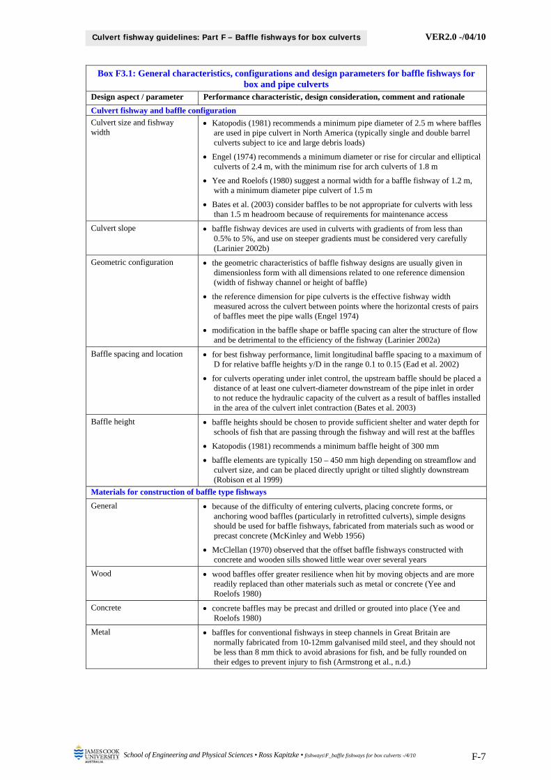
Box F3.1: General characteristics, configurations and design parameters for baffle fishways for box and pipe culverts
Design aspect / parameter Performance characteristic, design consideration, comment and rationale
Culvert fishway and baffle configuration
Culvert size and fishway width
Katopodis (1981) recommends a minimum pipe diameter of 2.5 m where baffles are used in pipe culvert in North America (typically single and double barrel culverts subject to ice and large debris loads)
Engel (1974) recommends a minimum diameter or rise for circular and elliptical culverts of 2.4 m, with the minimum rise for arch culverts of 1.8 m
Yee and Roelofs (1980) suggest a normal width for a baffle fishway of 1.2 m, with a minimum diameter pipe culvert of 1.5 m
Bates et al. (2003) consider baffles to be not appropriate for culverts with less than 1.5 m headroom because of requirements for maintenance access
Culvert slope baffle fishway devices are used in culverts with gradients of from less than 0.5% to 5%, and use on steeper gradients must be considered very carefully (Larinier 2002b)
Geometric configuration the geometric characteristics of baffle fishway designs are usually given in dimensionless form with all dimensions related to one reference dimension (width of fishway channel or height of baffle)
the reference dimension for pipe culverts is the effective fishway width measured across the culvert between points where the horizontal crests of pairs of baffles meet the pipe walls (Engel 1974)
modification in the baffle shape or baffle spacing can alter the structure of flow and be detrimental to the efficiency of the fishway (Larinier 2002a)
Baffle spacing and location for best fishway performance, limit longitudinal baffle spacing to a maximum of D for relative baffle heights y/D in the range 0.1 to 0.15 (Ead et al. 2002)
for culverts operating under inlet control, the upstream baffle should be placed a distance of at least one culvert-diameter downstream of the pipe inlet in order to not reduce the hydraulic capacity of the culvert as a result of baffles installed in the area of the culvert inlet contraction (Bates et al. 2003)
Baffle height baffle heights should be chosen to provide sufficient shelter and water depth for schools of fish that are passing through the fishway and will rest at the baffles
Katopodis (1981) recommends a minimum baffle height of 300 mm
baffle elements are typically 150 – 450 mm high depending on streamflow and culvert size, and can be placed directly upright or tilted slightly downstream (Robison et al 1999)
Materials for construction of baffle type fishways
General because of the difficulty of entering culverts, placing concrete forms, or anchoring wood baffles (particularly in retrofitted culverts), simple designs should be used for baffle fishways, fabricated from materials such as wood or precast concrete (McKinley and Webb 1956)
McClellan (1970) observed that the offset baffle fishways constructed with concrete and wooden sills showed little wear over several years
Wood wood baffles offer greater resilience when hit by moving objects and are more readily replaced than other materials such as metal or concrete (Yee and Roelofs 1980)
Concrete concrete baffles may be precast and drilled or grouted into place (Yee and Roelofs 1980)
Metal baffles for conventional fishways in steep channels in Great Britain are normally fabricated from 10-12mm galvanised mild steel, and they should not be less than 8 mm thick to avoid abrasions for fish, and be fully rounded on their edges to prevent injury to fish (Armstrong et al., n.d.)
VER2.0 -/04/10
School of Engineering and Physical Sciences • Ross Kapitzke • fishways\F_baffle fishways for box culverts -/4/10 F-8
Culvert fishway guidelines: Part F – Baffle fishways for box culverts
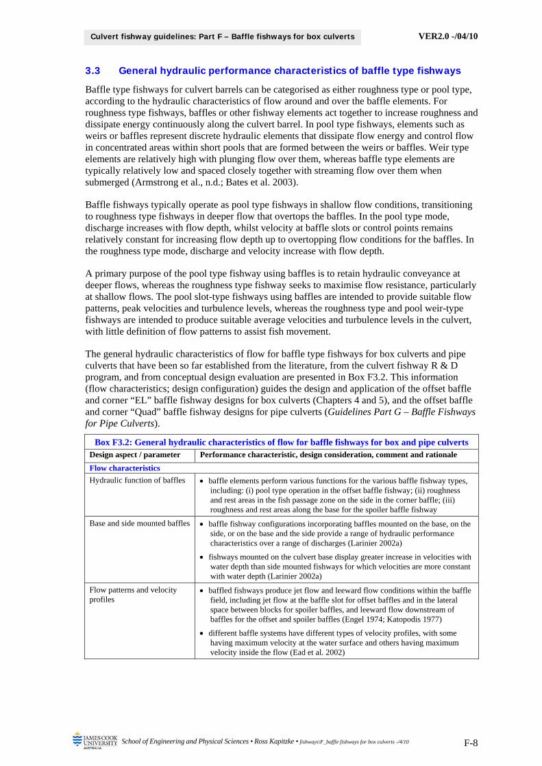
3.3 General hydraulic performance characteristics of baffle type fishways
Baffle type fishways for culvert barrels can be categorised as either roughness type or pool type, according to the hydraulic characteristics of flow around and over the baffle elements. For roughness type fishways, baffles or other fishway elements act together to increase roughness and dissipate energy continuously along the culvert barrel. In pool type fishways, elements such as weirs or baffles represent discrete hydraulic elements that dissipate flow energy and control flow in concentrated areas within short pools that are formed between the weirs or baffles. Weir type elements are relatively high with plunging flow over them, whereas baffle type elements are typically relatively low and spaced closely together with streaming flow over them when submerged (Armstrong et al., n.d.; Bates et al. 2003).
Baffle fishways typically operate as pool type fishways in shallow flow conditions, transitioning to roughness type fishways in deeper flow that overtops the baffles. In the pool type mode, discharge increases with flow depth, whilst velocity at baffle slots or control points remains relatively constant for increasing flow depth up to overtopping flow conditions for the baffles. In the roughness type mode, discharge and velocity increase with flow depth.
A primary purpose of the pool type fishway using baffles is to retain hydraulic conveyance at deeper flows, whereas the roughness type fishway seeks to maximise flow resistance, particularly at shallow flows. The pool slot-type fishways using baffles are intended to provide suitable flow patterns, peak velocities and turbulence levels, whereas the roughness type and pool weir-type fishways are intended to produce suitable average velocities and turbulence levels in the culvert, with little definition of flow patterns to assist fish movement.
The general hydraulic characteristics of flow for baffle type fishways for box culverts and pipe culverts that have been so far established from the literature, from the culvert fishway R & D program, and from conceptual design evaluation are presented in Box F3.2. This information (flow characteristics; design configuration) guides the design and application of the offset baffle and corner “EL” baffle fishway designs for box culverts (Chapters 4 and 5), and the offset baffle and corner “Quad” baffle fishway designs for pipe culverts (Guidelines Part G – Baffle Fishways for Pipe Culverts).
Box F3.2: General hydraulic characteristics of flow for baffle fishways for box and pipe culverts Design aspect / parameter Performance characteristic, design consideration, comment and rationale
Flow characteristics
Hydraulic function of baffles baffle elements perform various functions for the various baffle fishway types, including: (i) pool type operation in the offset baffle fishway; (ii) roughness and rest areas in the fish passage zone on the side in the corner baffle; (iii) roughness and rest areas along the base for the spoiler baffle fishway
Base and side mounted baffles baffle fishway configurations incorporating baffles mounted on the base, on the side, or on the base and the side provide a range of hydraulic performance characteristics over a range of discharges (Larinier 2002a)
fishways mounted on the culvert base display greater increase in velocities with water depth than side mounted fishways for which velocities are more constant with water depth (Larinier 2002a)
Flow patterns and velocity profiles
baffled fishways produce jet flow and leeward flow conditions within the baffle field, including jet flow at the baffle slot for offset baffles and in the lateral space between blocks for spoiler baffles, and leeward flow downstream of baffles for the offset and spoiler baffles (Engel 1974; Katopodis 1977)
different baffle systems have different types of velocity profiles, with some having maximum velocity at the water surface and others having maximum velocity inside the flow (Ead et al. 2002)

VER2.0 -/04/10
School of Engineering and Physical Sciences • Ross Kapitzke • fishways\F_baffle fishways for box culverts -/4/10 F-9
Culvert fishway guidelines: Part F – Baffle fishways for box culverts
Box F3.2: General hydraulic characteristics of flow for baffle fishways for box and pipe culverts Design aspect / parameter Performance characteristic, design consideration, comment and rationale
Flow regimes culvert fishways are designed to operate under open channel flow conditions, where a free surface exists between the water surface and the atmosphere, and the culvert functions with inlet or outlet control depending on the discharge, culvert slope and roughness, and tailwater level
Design configuration
Tailwater conditions to avoid adverse hydraulic conditions associated with local acceleration or formation of a hydraulic jump in the vicinity of the entrance to a fishway, the downstream end of the fishway should be drowned to a depth equivalent to the depth of water within the fishway (Armstrong et al., n.d.)
added roughness associated with the baffle type fishways typically raises the hydraulic profile through the culvert making it more difficult to match that of the downstream channel (Bates et al. 2003), and the increased hydraulic water surface drop at the culvert outlet may present a barrier to fish passage
3.4 General fish passage characteristics of baffle type culvert fishways
Culvert fishway devices are used to modify the hydraulic conditions of culvert waterway structures in order to provide suitable conditions (e.g. velocity, turbulence, flow patterns) for fish passage, whilst meeting other design requirements for the culvert such as transport, flow capacity and maintenance. Achieving hydraulic conditions that facilitate fish passage up to the fish passage design flow for the culvert is a vital aspect of culvert fishway design. Whereas the hydraulics of culvert baffles have been studied extensively, limited evaluation of adult or juvenile fish passage through baffled culverts has been undertaken (Bates et al. 2003).
Baffles and other culvert fishway devices are configured to produce one or more of the following hydraulic effects to enable upstream fish passage through the culvert waterway:
flow retardation – causing an overall velocity reduction and increased depth due to flow resistance associated with three dimensional flow submergence of the fishway elements
fish shelter – reduced velocity on the downstream side of fishway elements pooling – reduced velocity and increased depth on the upstream side of fishway elements flow circulation – causing backwater and upstream movement in the two dimensional flow
within the plane of the fishway baffles attraction flow – localised high velocity and flow concentration to attract upstream fish
movement at fishway elements (weirs, slots or baffles) acting as hydraulic controls
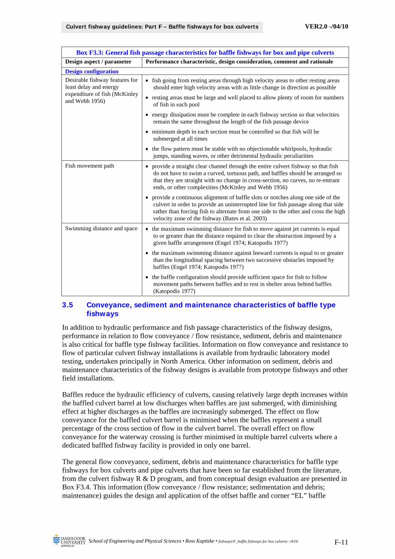
The general fish passage characteristics for baffle type fishways for box culverts and pipe culverts that have been so far established from the literature, from the culvert fishway R & D program, and from conceptual design evaluation are presented in Box F3.3. This information (fish movement behaviour; flow conditions for fish passage; effects of turbulence on fish; design configuration) guides the design and application of the offset baffle and corner “EL” baffle fishway designs for box culverts (Chapters 4 and 5), and the offset baffle and corner “Quad” baffle fishway designs for pipe culverts (Guidelines Part G – Baffle Fishways for Pipe Culverts).
Box F3.3: General fish passage characteristics for baffle fishways for box and pipe culverts Design aspect / parameter Performance characteristic, design consideration, comment and rationale
Fish movement behaviour
Movement paths and resting areas
the velocity field within a culvert fishway, particularly recirculating regions within the baffle set, defines movement paths and resting areas for ascending fish and the appropriate fishway type for various fish species (Ead et al. 2002)
fish typically use the path of least resistance as they swim upstream, moving against leeward flows for the greatest part of the way, using intermittent short spurts through jet flow as they pass obstacles, and resting in low velocity zones before moving upstream through the jet flow zones (Engel 1974)

VER2.0 -/04/10
School of Engineering and Physical Sciences • Ross Kapitzke • fishways\F_baffle fishways for box culverts -/4/10 F-10
Culvert fishway guidelines: Part F – Baffle fishways for box culverts
Box F3.3: General fish passage characteristics for baffle fishways for box and pipe culverts Design aspect / parameter Performance characteristic, design consideration, comment and rationale
Swim modes fish negotiating baffle fishways with hydraulic barriers and resting places commonly adopt a burst-rest pattern to advance through the culvert in stages, using burst swim mode to pass barriers at the baffles, and prolonged swim mode to travel or rest in regions of lower velocities in pools between the baffles (Ead et al. 2002)
fish passing through baffle fishways without resting typically use prolonged swim mode (Ead et al. 2002)
Flow conditions for fish passage
Pool and roughness type fishways
pool type culvert baffle fishway designs produce barrier velocity conditions at baffles or baffle slots, and provide shelter / resting places behind the baffles, commonly with a length of one to two baffle heights (Ead et al. 2002)
roughness type culvert baffle fishway designs act as roughness elements that increase resistance to flow and increase flow depth to enable fish to swim through the culvert without resting (Rajaratnam et al. 1990)
Flow depth and fish passage most baffles are designed to operate best when water flow is just overtopping them, with fishway effectiveness inversely proportional to the depth of water over them (McKinley and Webb 1956; Tollefson 1966; Yee and Roelofs 1980)
Shelter areas and recirculating flow
baffle type fishways typically produce less adverse overall velocity conditions within the culvert barrel than plain culverts, and provide some sheltering for fish behind baffles
pool type fishways such as the offset baffle also produce recirculating flow that has an upstream flow component in parts of the baffle cell, and assists in upstream fish movement through the fishway
Effects of turbulence on fish
Fish tolerance to turbulence an increase in the level of flow turbulence will typically affect the swimming capability of fish and increase the energetic cost of swimming through depletion of oxygen levels over a period of time (Enders et. al. 2007)
whereas certain types and characteristics of turbulence are inhibitory to fish passage, others may be conducive to fish passage as, for example, fish can take advantage of vortices (type of turbulence) under certain conditions to dramatically reduce the energetic cost of swimming (Enders et al. 2007)
flow conditions in steep baffle fishways with high velocity helical currents, are unsuitable for some fish species because of the aeration in the water column, and because some species are poor swimmers or unable to handle the large helical currents because of their small size (Armstrong et al., n.d.)
Helical currents, flow eddies and turbulence
increases in fishway size (fishway channel widths and baffle dimensions) will increase the size of helical currents and associated water velocities
increased recirculation zones and eddies in fishway pools may be too large and become traps for small fish through disorientation and inability to escape from the recirculation, thereby increasing transit times and compromising the efficiency of the fishway (Larinier 2002a; Tarrade et al. 2007)
Effects of baffle fishways on turbulence and fish passage
baffles may obstruct juvenile fish passage in some flow conditions by creating large-scale turbulence relative to the size of the fish (Bates et al. 2003)
tests by Enders et al. (2007) on fishway devices with vertically oriented and horizontally oriented flow circulation patterns showed that fish are more likely to enter and pass the fishway device with the vertically oriented vortex axes (circulation in horizontal plane), suggesting that culvert fishways with a vertical baffle design may be advantageous
VER2.0 -/04/10
School of Engineering and Physical Sciences • Ross Kapitzke • fishways\F_baffle fishways for box culverts -/4/10 F-11
Culvert fishway guidelines: Part F – Baffle fishways for box culverts
Box F3.3: General fish passage characteristics for baffle fishways for box and pipe culverts Design aspect / parameter Performance characteristic, design consideration, comment and rationale
Design configuration
Desirable fishway features for least delay and energy expenditure of fish (McKinley and Webb 1956)
fish going from resting areas through high velocity areas to other resting areas should enter high velocity areas with as little change in direction as possible
resting areas must be large and well placed to allow plenty of room for numbers of fish in each pool
energy dissipation must be complete in each fishway section so that velocities remain the same throughout the length of the fish passage device
minimum depth in each section must be controlled so that fish will be submerged at all times
the flow pattern must be stable with no objectionable whirlpools, hydraulic jumps, standing waves, or other detrimental hydraulic peculiarities
Fish movement path provide a straight clear channel through the entire culvert fishway so that fish do not have to swim a curved, tortuous path, and baffles should be arranged so that they are straight with no change in cross-section, no curves, no re-entrant ends, or other complexities (McKinley and Webb 1956)
provide a continuous alignment of baffle slots or notches along one side of the culvert in order to provide an uninterrupted line for fish passage along that side rather than forcing fish to alternate from one side to the other and cross the high velocity zone of the fishway (Bates et al. 2003)
Swimming distance and space the maximum swimming distance for fish to move against jet currents is equal to or greater than the distance required to clear the obstruction imposed by a given baffle arrangement (Engel 1974; Katopodis 1977)
the maximum swimming distance against leeward currents is equal to or greater than the longitudinal spacing between two successive obstacles imposed by baffles (Engel 1974; Katopodis 1977)
the baffle configuration should provide sufficient space for fish to follow movement paths between baffles and to rest in shelter areas behind baffles (Katopodis 1977)
3.5 Conveyance, sediment and maintenance characteristics of baffle type fishways
In addition to hydraulic performance and fish passage characteristics of the fishway designs, performance in relation to flow conveyance / flow resistance, sediment, debris and maintenance is also critical for baffle type fishway facilities. Information on flow conveyance and resistance to flow of particular culvert fishway installations is available from hydraulic laboratory model testing, undertaken principally in North America. Other information on sediment, debris and maintenance characteristics of the fishway designs is available from prototype fishways and other field installations.
Baffles reduce the hydraulic efficiency of culverts, causing relatively large depth increases within the baffled culvert barrel at low discharges when baffles are just submerged, with diminishing effect at higher discharges as the baffles are increasingly submerged. The effect on flow conveyance for the baffled culvert barrel is minimised when the baffles represent a small percentage of the cross section of flow in the culvert barrel. The overall effect on flow conveyance for the waterway crossing is further minimised in multiple barrel culverts where a dedicated baffled fishway facility is provided in only one barrel.
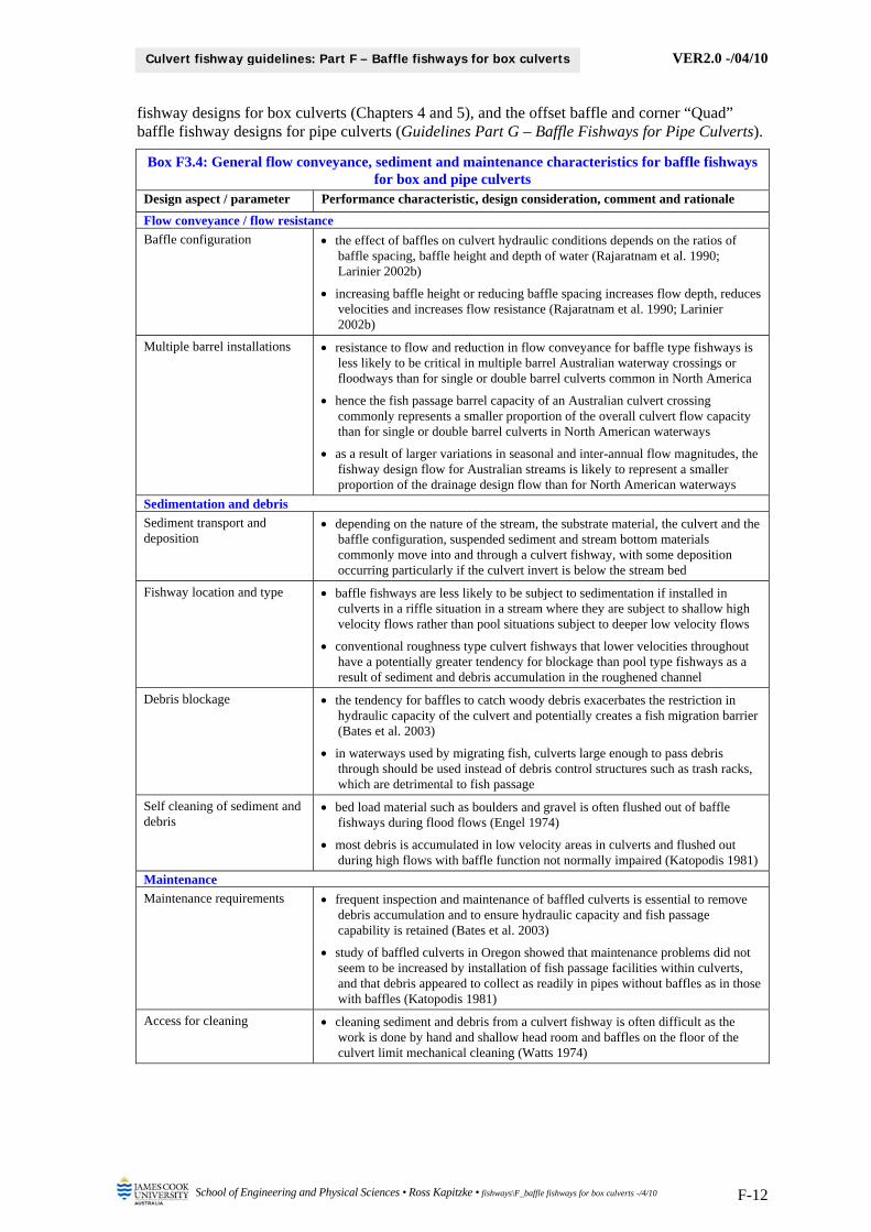
The general flow conveyance, sediment, debris and maintenance characteristics for baffle type fishways for box culverts and pipe culverts that have been so far established from the literature, from the culvert fishway R & D program, and from conceptual design evaluation are presented in Box F3.4. This information (flow conveyance / flow resistance; sedimentation and debris; maintenance) guides the design and application of the offset baffle and corner “EL” baffle
VER2.0 -/04/10
School of Engineering and Physical Sciences • Ross Kapitzke • fishways\F_baffle fishways for box culverts -/4/10 F-12
Culvert fishway guidelines: Part F – Baffle fishways for box culverts
fishway designs for box culverts (Chapters 4 and 5), and the offset baffle and corner “Quad” baffle fishway designs for pipe culverts (Guidelines Part G – Baffle Fishways for Pipe Culverts).
Box F3.4: General flow conveyance, sediment and maintenance characteristics for baffle fishways for box and pipe culverts
Design aspect / parameter Performance characteristic, design consideration, comment and rationale
Flow conveyance / flow resistance
Baffle configuration the effect of baffles on culvert hydraulic conditions depends on the ratios of baffle spacing, baffle height and depth of water (Rajaratnam et al. 1990; Larinier 2002b)
increasing baffle height or reducing baffle spacing increases flow depth, reduces velocities and increases flow resistance (Rajaratnam et al. 1990; Larinier 2002b)
Multiple barrel installations resistance to flow and reduction in flow conveyance for baffle type fishways is less likely to be critical in multiple barrel Australian waterway crossings or floodways than for single or double barrel culverts common in North America
hence the fish passage barrel capacity of an Australian culvert crossing commonly represents a smaller proportion of the overall culvert flow capacity than for single or double barrel culverts in North American waterways
as a result of larger variations in seasonal and inter-annual flow magnitudes, the fishway design flow for Australian streams is likely to represent a smaller proportion of the drainage design flow than for North American waterways
Sedimentation and debris
Sediment transport and deposition
depending on the nature of the stream, the substrate material, the culvert and the baffle configuration, suspended sediment and stream bottom materials commonly move into and through a culvert fishway, with some deposition occurring particularly if the culvert invert is below the stream bed
Fishway location and type baffle fishways are less likely to be subject to sedimentation if installed in culverts in a riffle situation in a stream where they are subject to shallow high velocity flows rather than pool situations subject to deeper low velocity flows
conventional roughness type culvert fishways that lower velocities throughout have a potentially greater tendency for blockage than pool type fishways as a result of sediment and debris accumulation in the roughened channel
Debris blockage the tendency for baffles to catch woody debris exacerbates the restriction in hydraulic capacity of the culvert and potentially creates a fish migration barrier (Bates et al. 2003)
in waterways used by migrating fish, culverts large enough to pass debris through should be used instead of debris control structures such as trash racks, which are detrimental to fish passage
Self cleaning of sediment and debris
bed load material such as boulders and gravel is often flushed out of baffle fishways during flood flows (Engel 1974)
most debris is accumulated in low velocity areas in culverts and flushed out during high flows with baffle function not normally impaired (Katopodis 1981)
Maintenance
Maintenance requirements frequent inspection and maintenance of baffled culverts is essential to remove debris accumulation and to ensure hydraulic capacity and fish passage capability is retained (Bates et al. 2003)
study of baffled culverts in Oregon showed that maintenance problems did not seem to be increased by installation of fish passage facilities within culverts, and that debris appeared to collect as readily in pipes without baffles as in those with baffles (Katopodis 1981)
Access for cleaning cleaning sediment and debris from a culvert fishway is often difficult as the work is done by hand and shallow head room and baffles on the floor of the culvert limit mechanical cleaning (Watts 1974)

VER2.0 -/04/10
School of Engineering and Physical Sciences • Ross Kapitzke • fishways\F_baffle fishways for box culverts -/4/10 F-13
Culvert fishway guidelines: Part F – Baffle fishways for box culverts
4 OFFSET BAFFLE FISHWAY DESIGN FOR BOX CULVERTS
The offset baffle fishway design is suited for application in relatively shallow, high velocity flow conditions in box culvert barrels, on culvert outlet aprons and in channelised waterway sections, where large reductions in velocity are required for fish passage through the waterway structure. The offset baffle design consists of a series of low baffles fixed to the culvert base and configured to provide sheltered areas and localised flow patterns to assist upstream fish passage, while maintaining flow continuity and self cleaning characteristics for sediment and debris passage through the fishway (Box F4.1).
The following sections discuss the design concepts and background, outline the design configuration and parameters, and describe the performance characteristics for the offset baffle fishway for box culverts. This is illustrated by reference to the prototype offset baffle fishways installed in University Creek in Townsville, within the culvert barrel for the Discovery Drive box culvert (Box F4.1; Kapitzke 2006b), and on the culvert outlet apron slab for the Solander Road culvert and causeway (Box F4.1; Kapitzke 2007c). The hydraulic and biological performance characteristics for the offset baffle fishway for box culverts incorporates material presented in the attached Appendix F1 – Discovery Drive Prototype Offset Baffle Fishway.
The overall suitability and performance characteristics for the offset baffle fishway for box culverts are summarised in Chapter 6, along with suggestions for further development and testing of the offset baffle fishway design. Design concepts, configuration and performance characteristics of baffle fishways (see Chapter 3) provide a context for design of the offset baffle fishway for box culverts.
Box F4.1: University Creek prototype offset baffle fishways (Source: Ross Kapitzke)
Discovery Drive box culvert offset baffle fishway in culvert barrel – looking upstream
in very shallow flow conditions (14/01/04)
Solander Road culvert / causeway offset baffle fishway on culvert apron slab – looking
downstream (10/04/06)
4.1 Design concept and configuration for offset baffle fishway
The offset baffle fishway was first developed and tested by McKinley and Webb (1956), and has been shown to be effective in providing favourable flow conditions for fish movement, as well as providing self cleaning flow characteristics due to spiralling flow along the edge of the fishway (Rajaratnam et al. 1988). Although once used extensively for box culverts and for pipe culverts in northern America and Europe, the offset baffle fishway has been used less in these regions in recent decades, having been replaced by the spoiler baffle, weir fishway or other designs. The offset baffle design has also lost favour for corrugated steel pipe (CSP) culverts in Canada and USA due to its configuration complexity relative to alternative baffle fishway designs, and the difficultly and cost in placing and attaching the oblong baffles over the pipe corrugations.
The standard offset baffle fishway configuration developed by McKinley and Webb (1956) consists of a series of low baffles on the base of the culvert, incorporating short (perpendicular) baffles at 90 to the side of the culvert, and oblong baffles at 30 to the culvert sides (Box F4.2).

VER2.0 -/04/10
School of Engineering and Physical Sciences • Ross Kapitzke • fishways\F_baffle fishways for box culverts -/4/10 F-14
Culvert fishway guidelines: Part F – Baffle fishways for box culverts
The baffle arrangement provides sheltered resting areas on the side of the fishway downstream of the perpendicular baffles, which are maintained for a range of flow depths including emerged and submerged baffle conditions. Under shallow flow conditions up to the height of the baffles, the offset baffle fishway functions in a similar manner to the vertical slot fishway for weirs, with highest velocities occurring in the slots between the baffles, and flow circulating between the baffles in the horizontal plane on the culvert base. The offset baffle design is suited to Australian situations as, like the vertical slot fishway, the resting pools and local higher velocity conditions between these pools allow fish to move in a burst and rest pattern through the fishway.
Box F4.2: Discovery Drive box culvert prototype offset baffle fishway configuration (Source: Kapitzke 2006b)
Discovery Drive culvert section showing fishway zones 1
Offset baffle fishway – Barrel 1 looking downstream 1
Offset Baffle Fishway in Barrel 1 – Plan View 1
Offset baffle fishway detail – showing perpendicular and oblong baffle arrangements 1
Offset baffle configuration in relation to fishway / culvert width (After: McKinley and Webb 1956)
Notes 1 This is a prototype facility in which the baffle fishway devices are constructed to suit adaptation and performance evaluation, and which includes provisions for monitoring and access that will not normally be incorporated into field installations of culvert fishway facilities
The offset baffle design used in the Discovery Drive box culvert prototype fishway on University Creek in Townsville (Kapitzke 2006b) provides an example of the design configuration for an offset baffle fishway facility (Box F4.2). The offset baffle design has also been used on the culvert outlet apron slab of the Solander Road prototype fishway on University Creek (Kapitzke 2007c). These fishway configurations are based directly on, or are adaptations of, the McKinley and Webb (1956) design, which defines the geometric characteristics of the baffles (baffle spacing, offset arrangement, slot width) relative to the width of the fishway or culvert barrel. The Discovery Drive and Solander Road fishways are prototype facilities in which the fishway
Fishway Zone 1A Offset Baffle
Barrel 2 Barrel 3
Hinged platform Handrails
Fishway Zone 3 Corner Baffle
Barrel 1 Fishway Zone 1A Zone 1B
Box culvert corner block
900 700 200
Oblong baffle
300
Perpendicular baffle
Dividing wall with handrail
1 4 5 6 7 8 9 10 11 12 13 2 3
Flow
1800
2000 1500 2000 2000
1000 2000
22 000
1800
Baffles (250 x 38 timber) – fix to mounting boards with steel brackets (130 x 55 mm)
1700
Approx 30 Oblong baffle
Perpendicular baffle
900
700
200
2000 1500
2000
1800
500 500
Mounting boards
Box culvert corner block
Flow 49.5% B
Fishway / culvert wall
300
900
12.5% B
38% B 26% B
112% B
B – Not less than 4 ft Not more than 6 ft
95% B
Fishway / culvert wall

VER2.0 -/04/10
School of Engineering and Physical Sciences • Ross Kapitzke • fishways\F_baffle fishways for box culverts -/4/10 F-15
Culvert fishway guidelines: Part F – Baffle fishways for box culverts
devices are constructed of light duty materials to suit adaptation and performance evaluation, and which includes provisions for monitoring and access that will not normally be incorporated into field installations of culvert fishway facilities.
The general characteristics, configurations and design parameters for the offset baffle fishway for box culverts that have been so far established from the literature, from the culvert fishway R & D program, and from conceptual design evaluation are presented in Box F4.3. This information (culvert fishway / baffle configuration; materials for construction) should be used to guide design and implementation of an offset baffle fishway for box culverts at a field site. Actual design provisions and configuration requirements for the culvert fishway facility should be established on the basis of the site characteristics (see Guidelines Part E – Fish Passage Design: Site Scale).
Box F4.3: Characteristics, configurations and design parameters for offset baffle fishway for box culverts
Design aspect / parameter Performance characteristic, design consideration, comment and rationale
Culvert fishway and offset baffle configuration
Culvert size and fishway width
the offset baffle design has been used successfully in the Discovery Drive box culvert prototype fishway, with a fishway channel width of 1.8 m in a culvert barrel width of 3.6 m (Kapitzke 2006b); a fishway channel width of 1.2 m is used on culvert fishways in Enoggera Creek and Cubberla Creek urban waterways in Brisbane
McKinley and Webb (1956) recommend a minimum width of the baffled fishway section of 1.5 m
Culvert slope the offset baffle fishway is designed for use in pipe, box or arch section culverts with slope between 2.5-5%, and can be adapted for shallower sloping culverts (between 1-2.5% slope) by shortening or removing the stub baffle (Bates 1999)
the offset baffle design has been used successfully in the Discovery Drive box culvert prototype fishway, with a culvert slope of 0.5 % (Kapitzke 2006b)
the offset baffle design has been used successfully on the outlet apron slab of the Solander Road culvert causeway prototype fishway, with an apron slab slope of 5.0 % (Kapitzke 2007c)
Geometric configuration the offset baffle fishway for box culverts operates most effectively for energy dissipation and fish passage with the oblong baffle at a 30-degree angle to the culvert wall (McKinley and Webb 1956)
the standard configuration for the offset baffle fishway for box culverts (McKinley and Webb 1956) has baffle spacing, offset arrangement and slot width defined relative to the width of the fishway or culvert barrel (Box F4.2)
Larinier (2002b) suggests a baffle spacing (L) for offset baffle culvert fishways of baffle height (p) and culvert slope (S) such that 0.25 < (S x L/p) < 0.35
Armstrong et al (n.d.) suggest spacing between baffle sets for the offset baffle fishway to ensure a minimum hydraulic drop of 0.06 m at baffle slots to assist passage of bed-load and to reduce the likelihood of gravel blocking baffles
Baffle height McKinley and Webb (1956) recommend a minimum baffle height for the offset baffle fishway for box culverts of 300 mm
a baffle height of 300 mm and a fishway width of 1.8 m is used in the Discovery Drive box culvert in Townsville (Kapitzke 2006b); a baffle height of 225 mm and a fishway width of 1.2 m is used on culvert fishways in Enoggera Creek and Cubberla Creek urban waterways in Brisbane
Larinier (2002b) recommends a minimum baffle height (p) for offset baffle culvert fishways in the range 0.20 – 0.30 m
Materials for construction of offset baffle fishways
General the Discovery Drive prototype offset baffle fishway, which provides for site adaptation and performance evaluation, is fabricated from hardwood timber and fixed to the culvert with mounting boards and steel brackets (Kapitzke 2006b)
more robust construction is preferred for permanent installations, and alternative construction materials such as precast concrete, steel or high strength plastics could be considered

VER2.0 -/04/10
School of Engineering and Physical Sciences • Ross Kapitzke • fishways\F_baffle fishways for box culverts -/4/10 F-16
Culvert fishway guidelines: Part F – Baffle fishways for box culverts
4.2 Hydraulic performance characteristics of offset baffle fishway
The offset baffle fishway operates as a pool type fishway in shallow flow conditions, transitioning to a roughness type fishway in deeper flows that overtop the baffles. The offset baffle design demonstrates desirable hydraulic characteristics in relation to fish passage, flow continuity, and self-cleaning features for a range of flow depths. For low flow through the fishway with emerged baffle conditions, flow continuity and recirculating flow in the horizontal plane of the baffle sets not only provide high and low velocity areas for fish sheltering and assistance in fish passage, but also enhance hydraulic conveyance, debris passage, and self-cleaning characteristics for the offset baffle fishway. For higher flows with submerged baffle conditions, spiraling flow over the oblong baffle, streaming flow over the perpendicular baffle and above the baffle slot, and the open top nature of the offset baffle culvert fishway enhance hydraulic conveyance, debris passage, and self-cleaning characteristics.
McKinley and Webb (1956) found that the offset baffle design was the most suitable fishway for box culverts over a range of slope and discharge conditions when evaluated in terms of effective energy dissipation, flow depth for fish, path for fish moving upstream from cell to cell, availability of resting places for fish, and other adverse hydraulic conditions such as whirlpools, jumps and high turbulence.
The general hydraulic characteristics of flow for the offset baffle fishway for box culverts that have been so far established from the literature, from the culvert fishway R & D program, and from conceptual design evaluation are presented in Box F4.4. This information (fishway type; flow characteristics) should be used to guide the design and implementation of an offset baffle fishway facility for box culverts at a field site. Actual design provisions and configuration requirements for the culvert fishway facility should be established on the basis of the site characteristics (see Guidelines Part E – Fish Passage Design: Site Scale). More detailed information on hydraulic performance characteristics obtained from field prototype and laboratory model testing of the offset baffle fishway for box culverts is presented in the attached Appendix F1 – Discovery Drive Prototype Offset Baffle Fishway.
Box F4.4: Hydraulic characteristics of flow for offset baffle fishway for box culverts Design aspect / parameter Performance characteristic, design consideration, comment and rationale
Fishway type
Hybrid roughness and pool type fishway
the offset baffle culvert fishway is a hybrid fishway that operates as a small two dimensional vertical slot pool type fishway at shallow flow, as a roughness type fishway at deeper flows submerging the baffles, and as a super active baffle fishway at larger flows (Larinier 2002b)
Similarities to vertical slot fishway
under shallow flow conditions, the offset baffle culvert fishway operates similar to a vertical slot fishway with streaming flow at low energy and velocity levels, energy dissipation with low turbulence levels, and streamlined flow continuity from cell to cell (Kapitzke 2006b)
the offset baffle culvert fishway simulates a vertical slot fishway at low flows up to the top of the baffles, with velocities at baffle slots remaining relatively constant for the full range of flow depths up to the baffle height, as they do for increased flow depths through the vertical slot fishway (Kapitzke 2006b)
Flow characteristics – emerged baffle condition (flow depth < baffle height)
Flow patterns – emerged baffle
for emerged flow conditions with depth less than one baffle height, the water jet passes through the baffle slot as streaming flow with recirculating flow in the horizontal plane of the baffles but minimal recirculating flow in the vertical plane, and follows a meandering path through the cell / baffle set to the next baffle slot downstream (Rajaratnam et al. 1988)
flow circulation occurs in a horizontal plane within the baffle sets, moving through the slot, along the oblong baffle side, and across to the inlet of the next baffle slot, where the flow splits and some returns upstream as reverse flow along the perpendicular baffle side (Kapitzke 2006b)

VER2.0 -/04/10
School of Engineering and Physical Sciences • Ross Kapitzke • fishways\F_baffle fishways for box culverts -/4/10 F-17
Culvert fishway guidelines: Part F – Baffle fishways for box culverts
Box F4.4: Hydraulic characteristics of flow for offset baffle fishway for box culverts Design aspect / parameter Performance characteristic, design consideration, comment and rationale
Velocities – Discovery Drive prototype fishway
velocities within the offset baffle fishway zone were consistently less than velocities in the adjacent plain culvert zones (up to 1.6 m/s), and flow depths were correspondingly greater within the fishway (Kapitzke 2006b)
for flows up to the baffle height of 300 mm, the baffle slot has the maximum velocity condition within the baffle fishway zone, typically reaching 0.5 m/s – 0.7 m/s (Kapitzke 2006b)
a backwater effect with virtually still water is produced downstream of the perpendicular baffles, and negative (upstream) velocities are produced in the recirculation zone along this side of the fishway (Kapitzke 2006b)
Flow characteristics – submerged baffle condition (flow depth > baffle height)
Flow patterns – submerged baffle
for submerged conditions with more than one baffle height flow depth, part of the flow goes straight downstream over the perpendicular baffles, another part flows obliquely over the oblong baffles in a spiraling fashion as plunging flow that interacts with recirculating flow in the lower plane below the baffle top, and the slot jet follows a straight path downstream (Rajaratnam et al. 1988)
spiraling flow over the oblong baffle forms a continuous roll along that side of the fishway, which extends across approximately one-third of the fishway width, and which tends to maintain the flow pattern below the top of the baffles after they are well overtopped (McKinley and Webb 1956)
subsurface flow through the baffle slot in the lower baffle zone sweeps upward and overtops the oblong baffles in a longitudinal spiral pattern, converging with other flow to form a prominent surface flow line down the centre of the fishway (Kapitzke 2006b)
Flow patterns – well submerged baffle
for flow much deeper than one baffle height, the upper flow layer passes straight downstream over the lower layer of recirculating lower-velocity flow bounded longitudinally by the baffles (Rajaratnam et al. 1988; Kapitzke 2006b)
Velocities – Discovery Drive prototype fishway
for flow depths of 350 mm – 500 mm (cf. baffle height of 300 mm), velocities through the baffle slot range from 0.7 m/s – 1.2 m/s, and are greater than for flow contained within the baffle height (Kapitzke 2006b)
subsurface velocities along the oblong baffle side are of similar magnitude to the baffle slot velocities, and velocities behind the perpendicular baffles in the lower flow zone are comparatively low and are directed upstream (velocity less than 0.2 m/s), indicating favourable rest conditions for fish (Kapitzke 2006b)
for flow depths of 450 mm – 500 mm, surface velocities above the baffle slot, along the wall at the oblong baffle, and along the centre of the fishway range from 0.5 m/s – 0.7 m/s; whilst velocities over the oblong baffle, and over the perpendicular baffle are in the range 0.7 m/s – 0.8 m/s (Kapitzke 2006b)
for flow depths of 400 mm – 500 mm, surface velocities (0.5 m/s – 0.8 m/s) in the zone above the baffles are still lower than the velocities (up to 1.6 m/s) for comparative flow depths in the plain culvert (Kapitzke 2006b)
4.3 Fish passage characteristics of offset baffle fishway
The offset baffle fishway design provides resting pools and local higher velocity conditions between these pools that allow fish to move in a burst and rest pattern through the fishway. Like the vertical slot fishway for weirs, the offset baffle culvert fishway is suited to a diverse range of juvenile and adult Australian fish species, which have a range of fish movement characteristics and which, in comparison to northern hemisphere species, generally require lower velocities and shorter bursts to travel through the culvert.
The configuration of the fishway produces hydraulic characteristics that assist upstream fish movement in a range of flow conditions including shallow flow contained within the baffles and deeper flow that overtops the baffles. This includes the following enabling hydraulic effects for upstream fish passage through the offset baffle fishway and culvert waterway:
flow retardation when baffles are emerged or submerged

VER2.0 -/04/10
School of Engineering and Physical Sciences • Ross Kapitzke • fishways\F_baffle fishways for box culverts -/4/10 F-18
Culvert fishway guidelines: Part F – Baffle fishways for box culverts
shelter downstream of the perpendicular baffles and the oblong baffles when baffles are emerged or submerged
pooling on the upstream side of the perpendicular baffles when baffles are emerged or submerged
flow circulation in the plane of the baffles when baffles are emerged localised high velocity conditions and flow concentration at baffle slots when baffles are
emerged and over perpendicular baffles when submerged
The general fish passage characteristics for the offset baffle fishway for box culverts that have been so far established from the literature, from the culvert fishway R & D program, and from conceptual design evaluation are presented in Box F4.5. This information (enabling hydraulic conditions; fish passage effectiveness; design configuration) should be used to guide the design and implementation of an offset baffle fishway facility for box culverts at a field site. Actual design provisions and configuration requirements for the culvert fishway facility should be established on the basis of the site characteristics (see Guidelines Part E – Fish Passage Design: Site Scale). More detailed information on fish passage performance characteristics obtained from field prototype and laboratory model testing of the offset baffle fishway for box culverts is presented in the attached Appendix F1 – Discovery Drive Prototype Offset Baffle Fishway.
Box F4.5: Fish passage characteristics for offset baffle fishway for box culverts Design aspect / parameter Performance characteristic, design consideration, comment and rationale
Enabling hydraulic conditions for fish passage – emerged baffle condition
Hydraulic control conditions for fish passage
barrier velocities at the baffle slot and low velocity resting and recirculation areas in pools within baffle sets provide control conditions for fish passage through the offset baffle fishway for flow depths up to one baffle height
Resting areas and flow circulation
circulating flow within the lower flow layers provides return flow to suit upstream fish movement in the baffle zone and low velocity resting areas for fish adjacent to the line of baffle slots, with minimal distance for fish to travel to pass upstream through the high velocity zones at the baffle slots
Attraction flows at baffle slots flow continuity through the fishway, and attraction flows in the concentrated jets at each baffle slot encourage fish to move into the fishway at the culvert outlet, and upstream through the baffle sets within the fishway
Fish movement paths – Discovery Drive prototype fishway
for flow contained within the baffle height, fish were observed to move up the fishway zone on the side of the perpendicular baffle, and rest downstream of the baffle before moving through the baffle slot into the next upstream baffle on their journey through the fishway (Kapitzke 2006b)
Enabling hydraulic conditions for fish passage – submerged baffle condition
Resting areas and low velocities
for deeper flow conditions submerging the baffles, the low velocity areas that are maintained downstream of the perpendicular baffles, and the moderate velocity areas that are directed downstream without circulation in the upper layers above the perpendicular baffles, provide conditions conducive to fish movement and resting along this side of the fishway
Pool areas and spiralling flow at baffles
for the offset baffle fishway operating on steep culvert slopes, shelter for fish is provided in the spiraling flow downstream of the oblong baffle, and pooling shelter is also provided upstream of the perpendicular baffles
the circular motion of the spiraling flow over the oblong baffle dissipates flow energy and reduces direct downstream velocities within the roll at the base of the oblong baffle, enabling fish to readily move upstream along the base of the baffle (McKinley and Webb 1956)
Fish movement paths – Discovery Drive prototype fishway
for deeper flows surcharging the baffles, fish were observed to negotiate through the fishway by resting behind the perpendicular baffles and then swimming over the top of the baffle to the next upstream baffle set rather than swimming through the gap between the baffles (Kapitzke 2006b)
Discovery Drive prototype fishway – fish passage effectiveness for 2004 monitoring event
Overall fish passage much larger numbers of Plotosid catfish and small fish migrated through the offset baffle fishway zone than through the plain culvert barrels in flow events in January and February 2004 (Kapitzke 2006b)

VER2.0 -/04/10
School of Engineering and Physical Sciences • Ross Kapitzke • fishways\F_baffle fishways for box culverts -/4/10 F-19
Culvert fishway guidelines: Part F – Baffle fishways for box culverts
Box F4.5: Fish passage characteristics for offset baffle fishway for box culverts Design aspect / parameter Performance characteristic, design consideration, comment and rationale
Emerged baffle condition (flow depth < baffle height)
for flow depths of 200 mm, upstream fish passage of 160 fish / hour was achieved through the fishway zone, compared with 15 fish / hour through the plain culvert barrels (Kapitzke 2006b)
the relative fish passage effectiveness (fish passage / hour / unit width) for adult Plotosid Catfish in the offset baffle fishway was at least 25 times that of the adjoining plain culvert barrels, although adversely affected by “supply” of fish to the culvert site (Kapitzke 2006b)
Effects of attraction flow the numbers of catfish using the fishway were lower (50 fish / hour) for no flow through the adjoining culvert barrel, than fish passage numbers achieved (120 fish / hour) when flow through the adjoining culvert barrel provided auxiliary attraction flow at the fishway entrance / culvert outlet (Kapitzke 2006b)
Design configuration
Fishway configuration the 30-degree angle for the oblong baffle provides the best configuration (baffle spacing, baffle angle, slot location) to ensure sheltered low velocity areas of adequate flow depth are provided in line with the high velocity jets through the slots, and to allow fish to swim in short bursts through the slots and enter resting areas adjacent to and parallel with the high velocity jet at the next upstream baffle set (McKinley and Webb 1956)
Baffle alignment the offset baffle fishway should provide a continuous alignment of baffle slots or notches along one side of the culvert in order to minimise the hydraulic resistance to high flows, and to provide an uninterrupted line for fish passage along that side rather than forcing fish to alternate from one side to the other and cross the high velocity zone of the fishway (Bates et al. 2003)
where possible, configure the perpendicular baffle of the offset baffle fishway along the outside culvert barrel wall adjacent to the edge of the waterway structure to provide connectivitiy for fish passage along the waterway edge
4.4 Conveyance, sediment and maintenance characteristics of offset baffle fishway
The offset baffle fishway restricts part of the culvert cross section and therefore affects flow conveyance and presents a potential sediment and debris trap requiring cleaning and maintenance within the culvert fishway barrel. The offset baffle design, however, has some inherent flow pattern characteristics that enhance hydraulic conveyance, debris passage, and self-cleaning characteristics for the fishway. The offset baffle fishway is most suited to installation in high velocity shallow flow environments where reduction in flow capacity in the culvert is less critical, and deposition of sediment in the fishway is least likely to occur.
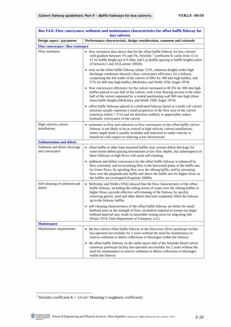
The flow conveyance, sediment, debris and maintenance characteristics for the offset baffle fishway for box culverts that have been so far established from the literature, from the culvert fishway R & D program, and from conceptual design evaluation are presented in Box F4.6. This information should be used to guide the design and implementation of an offset baffle fishway facility for box culverts at a field site. Actual design provisions and configuration requirements for the culvert fishway facility should be established on the basis of the site characteristics (see Guidelines Part E – Fish Passage Design: Site Scale). More detailed information on flow conveyance, sediment, debris and maintenance characteristics obtained from field prototype and laboratory model testing of the offset baffle fishway for box culverts is presented in the attached Appendix F1 – Discovery Drive Prototype Offset Baffle Fishway.
VER2.0 -/04/10
School of Engineering and Physical Sciences • Ross Kapitzke • fishways\F_baffle fishways for box culverts -/4/10 F-20
Culvert fishway guidelines: Part F – Baffle fishways for box culverts
Box F4.6: Flow conveyance, sediment and maintenance characteristics for offset baffle fishway for box culverts
Design aspect / parameter Performance characteristic, design consideration, comment and rationale
Flow conveyance / flow resistance
Flow resistance flow resistance data shows that for the offset baffle fishway for box culverts with gradient between 1% and 5%, Strickler 2 coefficient K varies from 15 to 21 for baffle height (p) of 0.30m, and L/p (baffle spacing to baffle height) ratios of between 5 and 20 (Larinier 2002b)
tests on the offset baffle fishway (slope 3.5%, unknown height) under high discharge conditions showed a flow conveyance efficiency for a fishway comprising the full width of the culvert of 69% for 300 mm high baffles, and 57% for 400 mm high baffles (McKinley and Webb 1956; Engel 1974)
flow conveyance efficiency for the culvert increased to 80.5% for 300 mm high baffles placed in one half of the culvert, with a free flowing section in the other half of the culvert separated by a central partitioning wall 900 mm high (three times baffle height) (McKinley and Webb 1956; Engel 1974)
offset baffle fishways placed in a dedicated fishway barrel in a multi cell culvert structure usually represent a small proportion of the flow area of the culvert waterway (often < 3 %) and are therefore unlikely to appreciably reduce hydraulic conveyance of the culvert
High velocity culvert installations
resistance to flow and reduction in flow conveyance in the offset baffle culvert fishway is not likely to be as critical in high velocity culvert installations, where ample head is usually available and reduction in outlet velocity is beneficial with respect to reducing scour downstream
Sedimentation and debris
Sediment and debris blockage and conveyance
offset baffle or other base mounted baffles may worsen debris blockage for water-borne debris passing downstream at low flow depths, but submergence of these fishways at high flows will assist self cleaning
sediment and debris conveyance for the offset baffle fishway is enhanced by flow continuity and recirculating flow in the horizontal plane of the baffle sets for lower flows, by spiraling flow over the oblong baffle, and by streaming flow over the perpendicular baffle and above the baffle slot for higher flows as the baffles are overtopped (Kapitzke 2006b)
Self-cleaning of sediment and debris
McKinley and Webb (1956) showed that the flow characteristics of the offset baffle fishway, including the rolling action of water over the oblong baffles at higher flows, provide effective self-cleaning of the fishway by quickly removing gravel, sand and other debris that had completely filled the fishway up to the fishway baffles
self-cleaning characteristics of the offset baffle fishway are better for small bedload sizes as the strength of flow circulation required to sweep out larger bedload material may result in unsuitable resting areas for migrating fish (Watts 1974; Utah Department of Transport, n.d.)
Maintenance
Maintenance requirements the box culvert offset baffle fishway in the Discovery Drive prototype facility has operated successfully for 5 years without the need for maintenance to remove sediment or debris collections or blockages within the fishway
the offset baffle fishway on the outlet apron slab of the Solander Road culvert causeway prototype facility has operated successfully for 2 years without the need for maintenance to remove sediment or debris collections or blockages within the fishway
2 Strickler coefficient K = 1/n [n= Manning’s roughness coefficient]

VER2.0 -/04/10
School of Engineering and Physical Sciences • Ross Kapitzke • fishways\F_baffle fishways for box culverts -/4/10 F-21
Culvert fishway guidelines: Part F – Baffle fishways for box culverts
5 CORNER “EL” BAFFLE FISHWAY DESIGN FOR BOX CULVERTS
The corner “EL” baffle fishway design is suited for application in culvert barrels where fish passage is required over a range of flow depths and velocities, including relatively deep and low velocity conditions. The corner “EL” baffle design consists of a series of “L” shaped baffles in the corner of the box culvert cell that are configured to provide sheltered areas and localised flow patterns to assist upstream fish passage, while maintaining flow continuity and an unobstructed pathway for sediment and debris passage through the culvert barrel (Box F5.1).
The following sections discuss the design concepts and background, outline the design configuration and parameters, and describe the performance characteristics for the corner “EL” baffle fishway for box culverts. This is illustrated by reference to the prototype fishway installed in the Discovery Drive box culvert in University Creek in Townsville (Kapitzke 2007b), and the corner “EL” baffle fishway design for the Bruce Highway Corduroy Creek to Tully road project (Kapitzke 2007a). The hydraulic and biological performance characteristics for the corner “EL” baffle fishway for box culverts incorporates material presented in the attached Appendix F2 – Discovery Drive Prototype Corner “EL” Baffle Fishway. Example designs are shown in the drawings for the Bruce Highway Corduroy Creek case study project corner “EL” baffle fishways for box culverts, included in Guidelines Part I.
The overall suitability and performance characteristics for the corner “EL” baffle fishway for box culverts are summarised in Chapter 6, along with suggestions for further development and testing of the corner “EL” baffle fishway design. Design concepts, configuration and performance characteristics of baffle fishways (see Chapter 3) provide a context for design of the corner “EL” baffle fishway for box culverts.
Box F5.1: Discovery Drive prototype corner “EL” baffle fishway on University Creek (Source: Ross Kapitzke)
Corner “EL” baffle fishway installed in culvert – looking downstream (15/12/05)
Corner “EL” baffle fishway in low flow conditions – looking downstream (11/04/06)
5.1 Design concept and configuration for corner “EL” baffle fishway
The corner “EL” baffle fishway is a new design developed by the author (Kapitzke 2007b) with the aim of providing for a range of flow conditions not catered for in the offset baffle or other fishway designs. A series of “L” shaped baffles in the corner of the culvert cell protrude a short distance from the culvert wall, and extend up the wall from the culvert floor (Box F5.2). This design is derived from the offset baffle design (perpendicular baffle extended vertically and oblong baffle removed) and adaptations of fishway designs for the side baffle (Engel 1974) and corner baffle (Bates 1999). The “L” shape of the corner “EL” baffle fishway differs from original designs for the corner baffle fishway for box culverts (Bates 1999), which incorporated a triangular baffle in the lower corner of the culvert.
The standard configuration for the corner “EL” baffle fishway has (perpendicular) baffles at 90 to the side of the culvert, but alternative configurations are under consideration (Kapitzke 2007b).
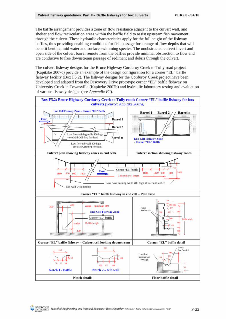
VER2.0 -/04/10
School of Engineering and Physical Sciences • Ross Kapitzke • fishways\F_baffle fishways for box culverts -/4/10 F-22
Culvert fishway guidelines: Part F – Baffle fishways for box culverts
The baffle arrangement provides a zone of flow resistance adjacent to the culvert wall, and shelter and flow recirculation areas within the baffle field to assist upstream fish movement through the culvert. These hydraulic characteristics apply for the full height of the fishway baffles, thus providing enabling conditions for fish passage for a range of flow depths that will benefit benthic, mid water and surface swimming species. The unobstructed culvert invert and open side of the culvert barrel remote from the baffles provide minimal obstruction to flow and are conducive to free downstream passage of sediment and debris through the culvert.
The culvert fishway designs for the Bruce Highway Corduroy Creek to Tully road project (Kapitzke 2007c) provide an example of the design configuration for a corner “EL” baffle fishway facility (Box F5.2). The fishway designs for the Corduroy Creek project have been developed and adapted from the Discovery Drive prototype corner “EL” baffle fishway on University Creek in Townsville (Kapitzke 2007b) and hydraulic laboratory testing and evaluation of various fishway designs (see Appendix F2).
Box F5.2: Bruce Highway Corduroy Creek to Tully road: Corner “EL” baffle fishway for box culverts (Source: Kapitzke 2007a)
Culvert plan showing fishway zones in end cells Culvert section showing fishway zones
Corner “EL” baffle fishway in end cell – Plan view
Corner “EL” baffle fishway – Culvert cell looking downstream Corner “EL” baffle detail
Notch details Floor baffle detail
3600 900
700
900 1800900 900 Flow
Culvert barrel length1800 18001800
Corner “EL” baffle
Low flow training walls 400 high at inlet and outlet Nib wall with notches
End Cell Fishway Zone – Corner “EL” Baffle
Barrel 2
Barrel n
Barrel 1
Low flow training walls 400 high – see Mid Cell dwg for detail
Low flow nib wall 400 high – see Mid Cell dwg for detail
Flow
Barrel 2 Barrel nBarrel 1
End Cell Fishway Zone - Corner “EL” Baffle
50 50 50
50
150
100 100 100
100
300
Notch 1 - Baffle Notch 2 – Nib wall
300
700
150
Notch See Detail 1
100
Low flow training wall – 400 high
End Cell Fishway Zone
400
300
300
varies
Corner “EL” baffle
varies – minimum 300
Baffle height
300
300
400
500
700
150
Notch See Detail 1
150
150
100 min.
500
Baffle height

VER2.0 -/04/10
School of Engineering and Physical Sciences • Ross Kapitzke • fishways\F_baffle fishways for box culverts -/4/10 F-23
Culvert fishway guidelines: Part F – Baffle fishways for box culverts
The general characteristics, configurations and design parameters for the corner “EL” baffle fishway for box culverts that have been so far established from the literature, from the culvert fishway R & D program, and from conceptual design evaluation are presented in Box F5.3. This information (culvert fishway and baffle configuration; materials for construction) should be used to guide the design and implementation of a corner “EL” baffle fishway facility for box culverts at a field site. Actual design provisions and configuration requirements for the culvert fishway facility should be established on the basis of the site characteristics (see Guidelines Part E – Fish Passage Design: Site Scale).
Box F5.3: Characteristics, configurations and design parameters for corner “EL” baffle fishway for box culverts
Design aspect / parameter Performance characteristic, design consideration, comment and rationale
Culvert fishway and corner “EL” baffle configuration
Culvert size and fishway width
the corner “EL” baffle design adopted for the Discovery Drive box culvert prototype fishway is installed within a culvert barrel width of 3.6 m (Kapitzke 2007b). The corner “EL” baffle design adopted for the Corduroy Creek Road box culvert fishways is installed within culverts of up to 3.6 m barrel width (Kapitzke 2007a)
in order to provide adequate clearance beside the baffles for a standard width corner “EL” baffle fishway, the suggested minimum culvert width is 1.5 m
Culvert slope the corner “EL” baffle design for the Discovery Drive box culvert prototype fishway is installed within a culvert with a slope of 0.5 % (Kapitzke 2006b)
although untested, the corner “EL” baffle design may be suitable for box culverts of up to 5 % slope
Geometric configuration the standard corner “EL” baffle design comprises an “L” shaped baffle perpendicular to the culvert wall. Alternative configurations are under consideration, including tilting the baffles from the horizontal plane and angling the baffles to the vertical plane
the standard corner “EL” baffle design has a horizontal leg that is 300 mm high and protrudes 700 mm from the culvert wall, and a vertical leg of varying height and a width of 300 mm from the wall (Box F5.2)
the standard 700 mm length of the horizontal baffle leg matches that of the offset baffle perpendicular baffle (0.38W) for a fishway width of 1800 mm. Variations in the length of the baffle leg may be adopted
provide notches in the horizontal and vertical legs of the baffles to assist localised fish movement past the baffles
Baffle spacing although not conclusively established, prototype fishway and hydraulic laboratory model testing indicates that the optimum baffle spacing for the corner “EL” baffle fishway in box culvert waterway structures is a function of the length of the horizontal leg rather than the width of the culvert barrel
until further established, the suggested longitudinal spacing of the baffles is in the range 2.25 LH – 3.0 LH (LH = length of horizontal leg), with a preferred spacing of 1800 mm (approximately 2.5 x leg length) for a horizontal baffle leg length of 700 mm (Kapitzke 2007a)
Baffle height the suggested height of the top of the horizontal baffle leg above the culvert floor is in the range 225 mm to 300 mm
the vertical baffle leg should extend to the level of the water surface corresponding to the maximum fish passage design flow profile through the fishway, and may extend to no closer than 300 mm below the culvert obvert
Materials for construction of corner “EL” baffle fishways
General the Discovery Drive prototype corner “EL” baffle fishway, which provides for site adaptation and performance evaluation, is fabricated from waterproof plywood and fixed to the culvert with steel brackets (Kapitzke 2006b)
more robust construction is preferred for permanent installations, and alternative construction materials such as precast concrete, steel or high strength plastics could be considered
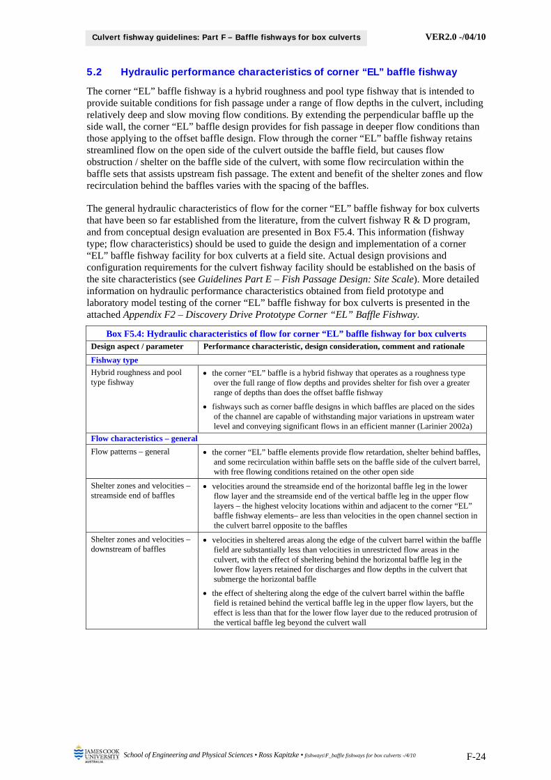
VER2.0 -/04/10
School of Engineering and Physical Sciences • Ross Kapitzke • fishways\F_baffle fishways for box culverts -/4/10 F-24
Culvert fishway guidelines: Part F – Baffle fishways for box culverts
5.2 Hydraulic performance characteristics of corner “EL” baffle fishway
The corner “EL” baffle fishway is a hybrid roughness and pool type fishway that is intended to provide suitable conditions for fish passage under a range of flow depths in the culvert, including relatively deep and slow moving flow conditions. By extending the perpendicular baffle up the side wall, the corner “EL” baffle design provides for fish passage in deeper flow conditions than those applying to the offset baffle design. Flow through the corner “EL” baffle fishway retains streamlined flow on the open side of the culvert outside the baffle field, but causes flow obstruction / shelter on the baffle side of the culvert, with some flow recirculation within the baffle sets that assists upstream fish passage. The extent and benefit of the shelter zones and flow recirculation behind the baffles varies with the spacing of the baffles.
The general hydraulic characteristics of flow for the corner “EL” baffle fishway for box culverts that have been so far established from the literature, from the culvert fishway R & D program, and from conceptual design evaluation are presented in Box F5.4. This information (fishway type; flow characteristics) should be used to guide the design and implementation of a corner “EL” baffle fishway facility for box culverts at a field site. Actual design provisions and configuration requirements for the culvert fishway facility should be established on the basis of the site characteristics (see Guidelines Part E – Fish Passage Design: Site Scale). More detailed information on hydraulic performance characteristics obtained from field prototype and laboratory model testing of the corner “EL” baffle fishway for box culverts is presented in the attached Appendix F2 – Discovery Drive Prototype Corner “EL” Baffle Fishway.
Box F5.4: Hydraulic characteristics of flow for corner “EL” baffle fishway for box culverts Design aspect / parameter Performance characteristic, design consideration, comment and rationale
Fishway type
Hybrid roughness and pool type fishway
the corner “EL” baffle is a hybrid fishway that operates as a roughness type over the full range of flow depths and provides shelter for fish over a greater range of depths than does the offset baffle fishway
fishways such as corner baffle designs in which baffles are placed on the sides of the channel are capable of withstanding major variations in upstream water level and conveying significant flows in an efficient manner (Larinier 2002a)
Flow characteristics – general
Flow patterns – general the corner “EL” baffle elements provide flow retardation, shelter behind baffles, and some recirculation within baffle sets on the baffle side of the culvert barrel, with free flowing conditions retained on the other open side
Shelter zones and velocities – streamside end of baffles
velocities around the streamside end of the horizontal baffle leg in the lower flow layer and the streamside end of the vertical baffle leg in the upper flow layers – the highest velocity locations within and adjacent to the corner “EL” baffle fishway elements– are less than velocities in the open channel section in the culvert barrel opposite to the baffles
Shelter zones and velocities – downstream of baffles
velocities in sheltered areas along the edge of the culvert barrel within the baffle field are substantially less than velocities in unrestricted flow areas in the culvert, with the effect of sheltering behind the horizontal baffle leg in the lower flow layers retained for discharges and flow depths in the culvert that submerge the horizontal baffle
the effect of sheltering along the edge of the culvert barrel within the baffle field is retained behind the vertical baffle leg in the upper flow layers, but the effect is less than that for the lower flow layer due to the reduced protrusion of the vertical baffle leg beyond the culvert wall

VER2.0 -/04/10
School of Engineering and Physical Sciences • Ross Kapitzke • fishways\F_baffle fishways for box culverts -/4/10 F-25
Culvert fishway guidelines: Part F – Baffle fishways for box culverts
Box F5.4: Hydraulic characteristics of flow for corner “EL” baffle fishway for box culverts Design aspect / parameter Performance characteristic, design consideration, comment and rationale
Flow characteristics – emerged baffle condition (flow depth < horizontal baffle height)
Flow patterns – emerged baffle
for flow depth at or below one standard baffle height, flow through the corner “EL” baffle fishway retains streamlined flow on the open side of the culvert outside the baffle field, but causes flow obstruction / shelter on the baffle side of the culvert and some horizontal flow circulation within the baffle sets
flow recirculation in a horizontal plane in the lower flow layer within baffle sets moves counter-clockwise toward the culvert wall, and for standard baffle spacings is established in a single large eddy between the baffles
Flow characteristics – submerged baffle (vertical baffle height > flow depth > horizontal baffle height)
Flow patterns – submerged baffle
for flow depth greater than one standard baffle height, flow through the corner “EL” baffle fishway retains streamlined flow on the open side of the culvert outside the baffle field, but causes flow obstruction / shelter on the baffle side of the culvert and some horizontal flow circulation within the baffle sets in the lower flow layer and in the upper flow layers
flow recirculation in a horizontal plane in the upper flow layers within the baffle sets moves in a counter-clockwise direction toward the culvert wall, and for standard baffle spacings is established in several eddies between the baffles that are smaller than the single eddy retained in the lower flow layer
compared with conditions in sheltered areas within baffle sets along the baffle side of the culvert in lower flow layer 1, the degree of shelter and recirculation within the baffle field and the size of the eddies is reduced in the upper flow layers due to the reduced protrusion of the baffles from the culvert side wall
Shelter zones and velocities, streamside end of baffles – hydraulic laboratory model of Discovery Drive prototype fishway
for flow depths of 300 mm – 900 mm (cf. baffle height of 300 mm), velocities at the streamside end of the horizontal baffle leg in the lower flow layer are in the range 1.1 m/s to 1.4 m/s, compared with velocities in the open channel section in the culvert barrel opposite the baffles ranging from 1.2 m/s to 1.7 m/s
for flow depths of 900 mm, velocities at the streamside end of the horizontal baffle leg in the lower flow layer and at the streamside end of the vertical baffle leg in the upper flow layers are in the range 1.1 m/s to 1.4 m/s, compared with velocities in the open channel velocities that range from 1.7 m/s to 1.9 m/s through these flow layers for this flow depth / discharge
Shelter zones and velocities, downstream of baffles – hydraulic laboratory model of Discovery Drive prototype fishway
for flow depths of 300 mm – 900 mm, velocities in sheltered areas along the edge of the culvert barrel within the baffle field in lower flow layer 1 are up to 0.3 m/s, compared with open channel velocities of 1.2 m/s to 1.7 m/s
for flow depths of 900 mm, velocities in sheltered areas along the edge of the culvert barrel within the baffle field in lower flow layer 1 are in the range 0.2 m/s to 0.3 m/s, compared with velocities in sheltered areas within the baffle field in upper flow layers, which are in the range 0.5 m/s to 0.7 m/s, apparently due to the reduced protrusion of the baffles from the culvert side wall
velocities in the open channel section in the culvert barrel opposite the baffles in flow layer 1 increase with discharge and flow depth in the culvert, whereas velocities in sheltered areas along the edge of the culvert barrel within the baffle field in flow layer 1 show only small increases with increased discharge and flow depth, indicating the corner “EL” baffle fishway provides conditions conducive to fish passage for a range of flow depths in the culvert
5.3 Fish passage characteristics of corner “EL” baffle fishway
The corner “EL” baffle fishway design provides shelter areas and flow recirculation within the baffle field that support the movement of fish in a burst and rest pattern through the fishway. The configuration of the fishway with the baffles extending up the culvert wall produces favourable hydraulic characteristics for fish passage in shallow and deep flows and provides for multiple fishway function that is likely to assist benthic, mid water and surface swimming species. This includes the following enabling hydraulic effects for upstream fish passage through the fishway:
flow retardation when baffles are emerged or submerged shelter downstream of the horizontal and vertical baffle legs when emerged or submerged

VER2.0 -/04/10
School of Engineering and Physical Sciences • Ross Kapitzke • fishways\F_baffle fishways for box culverts -/4/10 F-26
Culvert fishway guidelines: Part F – Baffle fishways for box culverts
pooling on the upstream side of the horizontal baffle legs when emerged or submerged flow circulation in a horizontal plane within the fields of the horizontal and vertical baffle
legs when emerged or submerged localised high velocity conditions and flow concentration on the outside ends of the
horizontal and vertical baffles when baffles are emerged or submerged
The general fish passage characteristics for the corner “EL” baffle fishway for box culverts that have been so far established from the literature, from the culvert fishway R & D program, and from conceptual design evaluation are presented in Box F5.5. This information (enabling hydraulic conditions; design configuration) should be used to guide design and implementation of a corner “EL” baffle fishway facility for box culverts at a field site. Actual design provisions and configuration requirements for the culvert fishway facility should be established on the basis of the site characteristics (see Guidelines Part E – Fish Passage Design: Site Scale). More detailed information on fish passage performance characteristics obtained from field prototype and laboratory model testing of the corner “EL” baffle fishway for box culverts is presented in the attached Appendix F2 – Discovery Drive Prototype Corner “EL” Baffle Fishway.
Box F5.5: Fish passage characteristics for corner “EL” baffle fishway for box culverts Design aspect / parameter Performance characteristic, design consideration, comment and rationale
Enabling hydraulic conditions for fish passage
Flow patterns the horizontal leg of the corner “EL” baffle fishway provides favourable hydraulic conditions to assist fish in moving around the end of the baffle when flow is contained within the baffle height, or over the top of the baffle when the baffles are submerged at shallow flow depths
the vertical leg of the corner “EL” baffle fishway provides favourable hydraulic conditions at a range of flow depths up to the top of the vertical baffle to assist fish moving throughout the water column depth, including on the bed of the stream and at the water surface
Hydraulic control conditions for fish passage
barrier velocities at the streamside end of the baffles provide control conditions for fish movement around the horizontal leg of the baffles in the lower flow layer, and around the vertical leg of the baffles for a range of flow depths up to the top of the baffles on the side wall
Resting areas and flow circulation
sheltered flow conditions and a tendency for flow recirculation within the baffle sets for both the lower and upper flow layers provide enhanced conditions for fish shelter and upstream movement between baffle sets
Attraction flows unrestricted flow in the open channel section of the culvert barrel opposite to the corner “EL” baffle improves attraction flow for fish into the corner “EL” baffle fishway culvert barrel, and locally accelerated flow around the streamside end of the baffles provides attraction flow for fish to move upstream
Design configuration
Fishway configuration extending the perpendicular baffles up the side of the culvert extends the depth of operation of the corner “EL” baffle fishway for fish passage in deeper flows and along the side of the culvert
providing small notches in the horizontal and vertical legs of the corner “EL” baffle fishway is likely to assist juvenile fish passage close to the culvert edges
Baffle alignment location of the corner “EL” baffle on one side throughout the culvert structure will allow fish to move between rest areas at baffles without crossing the flow
where possible, configure the perpendicular baffle of the corner “EL” baffle fishway along the outside wall of the culvert barrel adjacent to the edge of the waterway crossing structure to provide connectivitiy for fish passage along the edge of the waterway
5.4 Conveyance, sediment and maintenance characteristics of “EL” baffle fishway
The corner “EL” baffle fishway design provides favourable conditions for flow conveyance and for debris and sediment passage because the culvert invert and the open side of the culvert barrel remote from the baffles are largely unobstructed by the baffle components. This provides an

VER2.0 -/04/10
School of Engineering and Physical Sciences • Ross Kapitzke • fishways\F_baffle fishways for box culverts -/4/10 F-27
Culvert fishway guidelines: Part F – Baffle fishways for box culverts
advantage for use of the corner “EL” baffle fishway installation over use of the offset baffle or other fishway design in relatively low velocity environments where reduction in flow capacity in the culvert may be critical and deposition of sediment in the fishway is likely to occur.
The flow conveyance, sediment, debris and maintenance characteristics for the corner “EL” baffle fishway for box culverts that have been so far established from the literature, from the culvert fishway R & D program, and from conceptual design evaluation are presented in Box F5.6. This information should be used to guide the design and implementation of a corner “EL” baffle fishway facility for box culverts at a field site. Actual design provisions and configuration requirements for the culvert fishway should be established on the basis of the site characteristics (see Guidelines Part E – Fish Passage Design: Site Scale). More detailed information on flow conveyance, sediment, debris and maintenance characteristics obtained from field prototype and laboratory model testing of the corner “EL” baffle fishway for box culverts is presented in the attached Appendix F2 – Discovery Drive Prototype Corner “EL” Baffle Fishway.
Box F5.6: Flow conveyance, sediment and maintenance characteristics for corner “EL” baffle fishway for box culverts
Design aspect / parameter Performance characteristic, design consideration, comment and rationale
Flow conveyance / flow resistance
Flow resistance the corner “EL” baffle fishway causes minimal reduction in flow conveyance for the culvert because unobstructed flow conditions occur in the open channel section within the culvert, and the fishway baffles represent little obstruction within the overall culvert waterway area
the corner “EL” baffle fishways placed in a dedicated fishway barrel in a multi cell culvert structure usually represent a small proportion of the flow area of the culvert waterway (often < 3 %) and are therefore unlikely to appreciably reduce hydraulic conveyance of the culvert
Sedimentation and debris
Sediment and debris blockage and conveyance
the corner “EL” baffle fishway with baffles mounted on the culvert walls may worsen debris blockage for large water-borne debris such as tree branches passing downstream at high flow depths
although fine sediment may be deposited in sheltered areas downstream of the baffles, sediment and debris conveyance for the corner “EL” baffle fishway is enhanced by flow continuity along the open side of the box culvert, where no baffles are placed on the culvert base to obstruct sediment and debris passage
Self-cleaning of sediment and debris
the corner “EL” baffle fishway shows good self cleaning and through-flow attributes for sediment and debris due to the minimal obstruction to the culvert waterway area
Maintenance
Maintenance requirements the corner “EL” baffle fishway in the Discovery Drive prototype facility has operated successfully for 2 years without the need for maintenance to remove sediment or debris collections or blockages within the fishway

VER2.0 -/04/10
School of Engineering and Physical Sciences • Ross Kapitzke • fishways\F_baffle fishways for box culverts -/4/10 F-28
Culvert fishway guidelines: Part F – Baffle fishways for box culverts
6 OVERALL SUITABILITY OF BAFFLE FISHWAY DESIGNS
This chapter summarises overall suitability and performance characteristics for the offset baffle and corner “EL” baffle fishways for box culverts, based on information available from prototype fishway development and testing, hydraulic laboratory modeling, case study culvert fishway projects, and design concepts developed for these fishways. Suggestions for further development and testing of these fishways are also provided.
The major features that apply to the offset baffle fishway for box culverts are:
the offset baffle fishway is suited to shallow high velocity flow in culverts as it provides major reductions in culvert velocities, localises high velocity conditions to the control points between baffles, and increases flow depth to assist fish movement
this can be applied to steep culverts or culverts with low tailwater conditions, provided other fishway components (e.g. rock ramps / backflood weirs) are provided downstream to raise tailwater levels to the outlet water level through the fishway
the offset baffle fishway is less suited to low gradient culverts and deep slow water environments as the low culvert velocities will provide conditions more prone to sedimentation and blockage of the offset baffle fishway, and a simpler design (e.g. corner “EL” baffle) may be adequate to reduce velocities
the offset baffle fishway is a type of two dimensional vertical slot fishway that provides for fish passage through low velocity zones, shelter areas and flow circulation when flow is contained within the baffles, and low velocity zones and shelter areas within and adjacent to the baffle field when flow surcharges the baffles
when flow is contained within the baffles at depths up to one baffle height, the offset baffle fishway provides flow circulation and resting areas for fish and reduces maximum velocities through the structure compared with velocities in the adjoining plain culvert barrels
when surcharged at flow depths of up to three baffle heights, the offset baffle fishway retains favourable flow conditions for fish in the lower flow zone within the baffles, and reduces velocities in the flow zone immediately above the baffles
the low profile of the fishway and the flow continuity that is provided through the fishway baffle system minimises flow resistance and the effect on flow conveyance in the culvert
the offset baffle fishway shows good self-cleaning and through-flow attributes for sediment and debris due to the horizontal flow circulation within the baffle zone when flow is contained within the baffle zone, and the longitudinal spiral flow along the side wall when flow surcharges the baffles
The major features that apply to the corner “EL” baffle fishway for box culverts are:
the corner “EL” baffle fishway is suited to relatively deep low velocity flow in culverts as it provides localised reductions in culvert velocities for a range of flow depths
this can be applied to culverts with high tailwater conditions, or culverts where other fishway components (e.g. rock ramps / backflood weirs) are placed downstream to raise tailwater levels to the outlet water level through the fishway
the corner “EL” baffle fishway is less suited to high gradient culverts and shallow high velocity environments, where other fishway designs (e.g. offset baffle) may be required to provide appropriate reductions in culvert velocities
the corner “EL” baffle fishway provides for fish passage through low velocity zones, shelter areas and flow circulation for a range of flow depths in the culvert that will benefit benthic, mid water and surface swimming species
for flow contained within the fishway up to the top of the horizontal baffle, the fishway provides flow circulation and resting areas for fish and reduces maximum velocities through the structure compared with velocities in the adjoining plain culvert zones

VER2.0 -/04/10
School of Engineering and Physical Sciences • Ross Kapitzke • fishways\F_baffle fishways for box culverts -/4/10 F-29
Culvert fishway guidelines: Part F – Baffle fishways for box culverts
for flow up to the top of the vertical baffle, the fishway provides flow circulation, resting areas and reduced velocities through the full height of the baffles to assist fish moving throughout the fishway, including at the culvert bed and at the water surface
the low profile of the fishway and flow continuity that is provided through the unobstructed culvert base minimises flow resistance and the effect on flow conveyance in the culvert
the corner “EL” baffle fishway shows good self-cleaning and through-flow attributes for sediment and debris due to the minimal obstruction to the culvert waterway area
the corner “EL” baffle fishway is more readily constructed than the offset baffle fishway because of its simpler configuration
Suggested further development and testing of offset baffle and corner “EL” baffle fishways for box culverts includes the following, which can be undertaken through prototype fishways, hydraulic laboratory modeling, or case study culvert fishway projects:
hydraulic and biological performance characteristics of the offset baffle and corner “EL” baffle fishways with variations in culvert slope
hydraulic and biological performance characteristics of the corner “EL” baffle fishway with variations in longitudinal spacing of the baffles and the length of the horizontal baffle leg
adaptations of the corner “EL” baffle fishway design to examine tilting the baffles from the horizontal plane and angling the baffles to the vertical plane
adaptations of the corner “EL” baffle fishway design to examine the merits of providing notches on the horizontal and vertical baffle legs
examination and evaluation of techniques to provide appropriate attraction flows for fish entrance to the fishway components
examination and evaluation of techniques to provide appropriate hydraulic characteristics for transitions between fishway components
examination of turbulence characteristics of the offset baffle and corner “EL” baffle fishways and the relationship to fishway flow, culvert slope, and fishway design
examination of flow resistance / conveyance characteristics of the offset baffle and corner “EL” baffle fishways and the relationship to fishway flow, culvert slope, and fishway design
evaluation of biological performance characteristics of the various baffle designs, including fish passage effectiveness and fish movement behaviour for the fishways
adaptations of the offset baffle and corner “EL” baffle fishway designs to improve sediment and debris shedding of the baffles (e.g. profiling upstream face)
comparative evaluation of performance characteristics of the offset baffle, corner “EL” baffle and other baffle fishway designs for a range of culvert configurations and flows
examination of materials for fabrication and installation of the baffle fishways and to provide for ready fixing of the baffles to the culvert base and walls

VER2.0 -/04/10
School of Engineering and Physical Sciences • Ross Kapitzke • fishways\F_baffle fishways for box culverts -/4/10 F-30
Culvert fishway guidelines: Part F – Baffle fishways for box culverts
7 BIBLIOGRAPHY Armstrong, G., Aprahamian, M., Fewings, A., Gough, P., Reader, N., and Varallo, P., n.d., Fish passes,
Guidance notes on the legislation, selection and approval of fish passes in England and Wales. Bates, K. 1999, Fish passage at road culverts, Washington Department of Fish and Wildlife, 49 p. Bates, K., Barnard, R., Heiner, B., Klavas, J.P., and Powers, P.D., 2003, Design of road culverts for fish
passage, Washington Department of Fish and Wildlife. Boubee, J. Jowett, I., Nichols, S. Williams, E. 1999, Fish passage at culverts, A review with possible
solutions for New Zealand indigenous species, Report prepared for NIWA, Department of Conservation, Wellington, New Zealand.
Bryant, M.D 1981, Evaluation of a small diameter baffled culvert for passing juvenile salmonids, United States Department of Agriculture Forest Service Pacific Northwest Forest and Range Experiment Station Research Note PNW-384, available at: http://www.fs.fed.us/pnw/pubs/pnw_rn384.pdf.
Dupont, E. 2004, “Trout road crossing problem in Belgium”, Proceedings of 5th International Symposium on Ecohydraulics, Madrid, Spain, IAHR Madrid, pp 905-910.
Ead, S.A., Rajaratnam, N. and Katopodis, C. 2002, “A generalized study of the hydraulics of culvert fishways”, Journal of Hydraulic Engineering, ASCE.
Enders, E.C., Castro-Santos, E., Peake, S., Haro, A. and Scruton, D.A. 2007, “The effects of horizontally- and vertically-oriented vortices on the swimming performance of upstream migrating brook charr (Salvelinus fontinalis)”, Proceedings of the 6th International Conference on Ecohydraulics, Christchurch 18-23 February 2007.
Engel, P. 1974, Fish facilities for culverts of the McKenzie Highway, National Water Research Institute, Burlington Ontario 33p.
Evans, W. A., and Johnston, F B 1974, Fish migration and fish passage: A practical guide to solving fish passage problems, USDA Forest Service Region 5, 43 p.
Gebhards, S. and Fisher, J. 1972, Fish passage culvert installations, report for Idaho Department of Fish and Game, Boise Idaho.
Kapitzke, I.R. 2006a, Bruce Highway Corduroy Creek to Tully planning study Provisions for fish passage – Road corridor scale Assessment Task 1A, report to Maunsell Australia and Department of Main Roads.
Kapitzke, I.R. 2006b, Discovery Drive offset baffle fishway for box culverts (Prototype Fishway # 1): Case study project design and prototype monitoring report to April 2005, report to Dept of Main Roads.
Kapitzke, I.R. 2006c, Douglas Arterial Project rock ramp fishway for open channels (Prototype Fishway # 2): Case study project design and prototype monitoring report to April 2005, report to Dept Main Roads.
Kapitzke, I.R. 2007a, Bruce Highway Corduroy Creek to Tully High School Provisions for fish passage – Preliminary Design Assessment Tasks 1B and 2, report to Maunsell Australia and Dept of Main Roads.
Kapitzke, I.R. 2007b, Discovery Drive corner baffle fishway for box culverts (Prototype Fishway # 4): Case study project design and prototype monitoring report to April 2006, report to Dept of Main Roads.
Kapitzke, I.R. 2007c, Solander Road pipe culvert fishway (Prototype Fishway # 3): Case study project design and prototype monitoring report to April 2006, report to Department of Main Roads.
Katopodis, C. 1977, “Design of culverts for fish passage”, Proceedings of 3rd National Hydrotechnical Conference, Quebec.
Katopodis, C. 1981, “Review of fish passage methods for freshwater species”, Proceedings of Resource Roads Workshops, Whitehorse and Yellowknife, 16-20 March 1981.
Kopeinig, T., Boubée, J. and Rutschmann, P. 2007, “Numerical study of flow through a culvert – investigation on various modifications using a 3D turbulent Navier-Stokes code”, Proceedings of the 6th International Conference on Ecohydraulics, Christchurch 18-23 February 2007.
Larinier, M. 2002a, “Baffle fishways”, Chapter 6 in Vineux, E. and Larinier, M. (Eds), Fishways: Biological basis, design criteria and monitoring, Supplement No 364 to Bulletin Francais de la Peche et de la Pisciculture, p 83 – 101, United Nations FAO.
Larinier, M. 2002b, “Fish passage through culverts, rock weirs and estuarine obstructions”, Chapter 8 in Vineux, E. and Larinier, M. (Eds), Fishways: Biological basis, design criteria and monitoring, Supplement No 364 to Bulletin Francais de la Peche et de la Pisciculture, p 119 – 134, United Nations FAO.
McClellan, T. 1970, Fish passage through highway culverts, report for US Department of Transportation, Federal Highway Administration.
McKinley, W.R. and R.D. Webb. 1956. "A proposed correction of migratory fish problems at box culverts". Washington Department of Fisheries Fish Research Papers 1(4): 33-45, Olympia, WA.

VER2.0 -/04/10
School of Engineering and Physical Sciences • Ross Kapitzke • fishways\F_baffle fishways for box culverts -/4/10 F-31
Culvert fishway guidelines: Part F – Baffle fishways for box culverts
Muraoka, K., Hirano, T. and Amano, K. 2007, “Hydraulics of the V shaped corner baffle (Half Denil Fishway) designed for paddy fields”, Proceedings of the 6th International Conference on Ecohydraulics, Christchurch 18-23 February 2007.
Rajaratnam, N., Katopodis, C. and Fairbairn 1990, “Hydraulics of culvert fishways V: Alberta Fish Weirs and Baffles”, Canadian Journal of Civil Engineering, 17:6, pp 1015-1021.
Rajaratnam, N., Katopodis, C. and Lodewyk, S. 1988, “Hydraulics of offset baffle culvert fishways”, Canadian Journal of Civil Engineering, 15(6): 1043-1051.
Robison, G., Mirati, A. and Allen, M. 1999, Oregon road/stream crossing restoration guide, prepared for Oregon Department of Fish and Wildlife.
Tarrade, L., Texier, A., David, L. and Larinier, M. 2007, “Influence of a cylinder on the turbulent flow in vertical slot fishways”, Proceedings of the 6th International Conference on Ecohydraulics, Christchurch 18-23 February 2007.
Tollefson, T.C. 1966, Facilities at culvert installations, Washington Department of Fisheries, Olympia, WA.
Utah Department of Transport, n.d., Manual of instruction – Roadway drainage, surface water environment, available at: www.udot.utah.gov/dl.php/tid=826/save/Chapter%2015.pdf
Washington Department of Fish and Wildlife 2000, Fishway guidelines for Washington State, available at: www.wa.gov/wdfw/hab/ahg/fishguid.pdf.
Watts, F. J. 1974, Design of culvert fishways, Water Resources Research Institute, University of Idaho, Moscow, ID.
Yee, C.S. Roelofs, T.D. 1980, “Planning forest roads to protect salmonid habitat”, Meehan, W.R. ed, Influence of forest and rangeland management on anadromous fish habitat in western north America, General Technical Report PNW-109, US Department of Agriculture Forest Service Pacific Northwest Forest and Range Experiment Station, available at: http://www.fs.fed.us/pnw/pubs/pnw_gtr109.pdf#xml=http://www.fs.fed.us/cgi-bin/texis/searchallsites/search.allsites/xml.txt?query=fish+passage+culvert+baffle&db=allsites&id=41c0cbcb0
Ross Kapitzke James Cook University School of Engineering and Physical Sciences April 2010 – VER2.0

VER2.0 -/04/10
Ross Kapitzke • JCU Engineering • DMR culvert fishway guidelines • fishways\F_baffle fishways for box culverts -/4/10
Culvert fishway guidelines: Part F – Baffle fishways for box culverts
APPENDIX F1 – DISCOVERY DRIVE PROTOTYPE OFFSET BAFFLE FISHWAY
VER2.0 -/04/10
School of Engineering and Physical Sciences • Ross Kapitzke • fishways\Appendix F1_discovery drive offset baffle -/4/10 F1-i
Culvert fishway guidelines: Appendix F1 – Discovery Drive offset baffle
James Cook University School of Engineering and Physical Sciences Culvert Fishway Design Guidelines: Part F – Baffle Fishways for Box Culverts Appendix F1 – Discovery Drive Prototype Offset Baffle Fishway Contents
1 DISCOVERY DRIVE OFFSET BAFFLE FISHWAY FACILITY 1
2 PROTOTYPE OFFSET BAFFLE FISHWAY HYDRAULIC MONITORING 3 2.1 Hydraulic monitoring equipment and methods 3 2.2 Hydraulic monitoring results for 2004 and 2005 5 2.3 Summary of findings – physical monitoring of prototype offset baffle 5
3 PROTOTYPE OFFSET BAFFLE FISHWAY BIOLOGICAL MONITORING 10 3.1 Biological monitoring equipment and methods 10 3.2 Biological monitoring results for 2004 and 2005 11 3.3 Summary of findings – biological monitoring of prototype offset baffle 13
4 HYDRAULIC LABORATORY MODELLING 15 4.1 Hydraulic laboratory modelling equipment and methods 15 4.2 Results from hydraulic laboratory modelling 15 4.3 Summary of findings – offset baffle hydraulic laboratory modelling 18
5 BIBLIOGRAPHY 19

VER2.0 -/04/10
School of Engineering and Physical Sciences • Ross Kapitzke • fishways\Appendix F1_discovery drive offset baffle -/4/10 F1-1
Culvert fishway guidelines: Appendix F1 – Discovery Drive offset baffle
James Cook University School of Engineering and Physical Sciences Culvert Fishway Design Guidelines: Part F – Baffle Fishways for Box Culverts Appendix F1 – Discovery Drive Prototype Offset Baffle Fishway
1 DISCOVERY DRIVE OFFSET BAFFLE FISHWAY FACILITY
The offset baffle fishway for box culverts (Prototype Fishway #1) was developed in the Discovery Drive box culvert crossing of University Creek in 2002 (Boxes F1A.1 and F1A.2). This is a full-size facility constructed in one culvert barrel, with dedicated access and monitoring facilities incorporated into the culvert structure to allow hydraulic and biological monitoring of fishway performance during flow events in University Creek. The Discovery Drive crossing itself consists of a 3-cell rectangular box culvert (3600 x 3000 mm), with a barrel length of 22 metres, and an invert slope of 1 in 200 or 0.5 % (fall 0.01 m over culvert length). The culvert has a horizontal apron at the outlet, and a downstream drop of about 1 metre to the stream bed level.
The offset baffle fishway design, developed and tested for box culverts by McKinley and Webb (1956), is a pool type fishway that is intended to provide suitable conditions for fish passage under relatively high velocity conditions in the culvert. The fishway consists of a series of low baffles on the base of the culvert, incorporating short (perpendicular) baffles at 90 to the side of the culvert, and oblong baffles at approximately 30 to the culvert sides. The geometric configuration of the baffles (baffle spacing, offset arrangement, slot width) is defined relative to the width of the fishway or culvert barrel. The offset baffle fishway device for the Discovery Drive culvert is 1800 mm wide and comprises half of one culvert cell (Boxes F1A.1 and F1A.2).
The offset baffle fishway was installed in one culvert barrel in order to overcome fish migration barriers associated with high velocities, regular cross section and lack of resting place in the barrel. Overall, barriers to fish migration at the culvert without the fishway may be produced in various flow conditions as a result of the following (see Guidelines Part F):
water surface drop at the culvert outlet under low tailwater conditions 1 shallow water depths on the downstream apron and within the culvert at low flows high velocities within the culvert barrel regular cross section and lack of resting place along the culvert barrel excess turbulence (hydraulic jump) within the culvert barrel or at the culvert outlet high velocities and lack of shelter at the culvert inlet during low and high flows
Box F1A.1: Discovery Drive offset baffle fishway for box culverts (Prototype #1) established in University Creek (Source: Ross Kapitzke)
Offset baffle fishway in culvert Barrel 1 – on right looking upstream (16/01/04)
Offset baffle fishway and plain culvert barrel section – looking upstream (15/01/04)
1 Tailwater conditions for the Discovery Drive box culvert are subject to fluctuating downstream water levels associated with bed deposition or erosion at the downstream riffle control in University Creek.
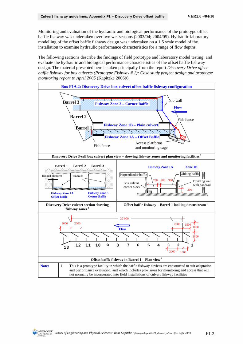
VER2.0 -/04/10
School of Engineering and Physical Sciences • Ross Kapitzke • fishways\Appendix F1_discovery drive offset baffle -/4/10 F1-2
Culvert fishway guidelines: Appendix F1 – Discovery Drive offset baffle
Monitoring and evaluation of the hydraulic and biological performance of the prototype offset baffle fishway was undertaken over two wet seasons (2003/04; 2004/05). Hydraulic laboratory modelling of the offset baffle fishway design was undertaken on a 1:5 scale model of the installation to examine hydraulic performance characteristics for a range of flow depths.
The following sections describe the findings of field prototype and laboratory model testing, and evaluate the hydraulic and biological performance characteristics of the offset baffle fishway design. The material presented here is taken principally from the report Discovery Drive offset baffle fishway for box culverts (Prototype Fishway # 1): Case study project design and prototype monitoring report to April 2005 (Kapitzke 2006b).
Box F1A.2: Discovery Drive box culvert offset baffle fishway configuration
Discovery Drive 3-cell box culvert plan view – showing fishway zones and monitoring facilities 1
Discovery Drive culvert section showing fishway zones 1
Offset baffle fishway – Barrel 1 looking downstream 1
Offset baffle fishway in Barrel 1 – Plan view 1
Notes 1 This is a prototype facility in which the baffle fishway devices are constructed to suit adaptation and performance evaluation, and which includes provisions for monitoring and access that will not normally be incorporated into field installations of culvert fishway facilities
Access platforms and monitoring cage
Barrel 2
Barrel 1
Fishway Zone 1A – Offset Baffle
Flow
Fish fence
Fish fence
Barrel 3
Fishway Zone 1B – Plain culvert
Fishway Zone 3 – Corner BaffleNib wall
1 4 5 6 7 8 9 10 11 12 13 2 3
Flow
1800
2000 1500 2000 2000
1000 2000
22 000
1800
Fishway Zone 1A Offset Baffle
Barrel 2 Barrel 3
Hinged platform Handrails
Fishway Zone 3 Corner Baffle
Barrel 1 Fishway Zone 1A Zone 1B
Box culvert corner block
900 700 200
Oblong baffle
300
Perpendicular baffle
Dividing wall with handrail
VER2.0 -/04/10
School of Engineering and Physical Sciences • Ross Kapitzke • fishways\Appendix F1_discovery drive offset baffle -/4/10 F1-3
Culvert fishway guidelines: Appendix F1 – Discovery Drive offset baffle
2 PROTOTYPE OFFSET BAFFLE FISHWAY HYDRAULIC MONITORING
An integrated monitoring, modelling and evaluation plan was developed for the fishway in order to evaluate performance in accordance with the design objectives for the facility. This included hydraulic and biological monitoring of the prototype fishway, hydraulic laboratory modelling of fishway designs, and field studies of University Creek to confirm stream hydrology, culvert hydraulics, fish passage behaviour and the effects of culvert remediation works.
Physical and biological monitoring of the prototype fishway examined the hydraulic characteristics of the fishway devices, their effects on fish migration and behaviour, and the overall effectiveness of the facility. Comparative observations of flow characteristics and fish passage performance were made of the culvert fishways, the plain culvert barrels, and adjoining stream sections upstream and downstream of the structure. Field measurements and observations were made during periods of relevant flow to correlate with theoretical data obtained from the desk top studies. This included manipulation of flow and fish barrier conditions through the culvert in order to study hydraulic characteristics and fish behaviour under varying conditions.
The hydraulic monitoring used a flow meter to determine velocity measurements, and direct measurements, observations, photographs and video to examine water depths and flow profiles associated with the fishway and the culvert during periods of relevant flow. Water depths in the fishway were measured using a number of gauge boards attached to the culvert walls, and flow meter measurements were undertaken by access along the culvert floor during low level flows, subject to operational safety provisions. The effect of the fishway on flow velocities throughout the culvert was determined, and flow velocity patterns and profiles compiled to allow correlation with the theoretical and laboratory data obtained from desktop studies and hydraulic modelling.
The aims of physical / hydraulic field monitoring of the prototype and in the stream were to:
examine and measure flow depth, velocity, flow pattern and discharge at various locations within the prototype fishway for a range of flow conditions and discharges
examine the potential for sediment / debris obstruction in the fishway and erosion and sedimentation effects in the stream associated with the fishway
integrate hydraulic prototype monitoring with hydraulic field monitoring in adjoining stream reaches, hydraulic laboratory modelling, and associated desktop studies
integrate hydraulic monitoring and evaluation with biological monitoring and other studies contribute to evaluation of the prototype culvert fishway and to determination of design
parameters for other culvert fishway facilities. follow operational and safety procedures for access and monitoring of the prototype facility
2.1 Hydraulic monitoring equipment and methods
All flow observations and measurements at the Discovery Drive prototype fishway were undertaken under low flow conditions (flow depths less than 0.5 m deep through the fishway). Nib wall flow control boards, which are part of the monitoring facilities at the culvert, were manipulated to direct flow through the fishway zones or the plain culvert barrels, and velocity measurements were obtained within fishway Zone 1A (offset baffle) and Zone 1B (plain culvert), with particular emphasis on baffle sets 1-2, 6-7, and 12-13 within fishway Zone 1A (Boxes F1A.3 and F1A.4). Gauge board readings to measure the water depth in the culvert and fishway were obtained in Barrels 1 and 3 at the locations shown in Box F1A.3. Velocity measurements were taken using the Swoffer Instruments Model 3000 data logging flow meter (Box F1A.4), and observational data on flow patterns were recorded using still and video photography.
A series of monitoring cases were undertaken during flow events in January 2004, February 2004, and January 2005, with various combinations of headwater and tailwater conditions on the fishway, and with either or both of fishway Zone 1A and Zone 1B flowing. Two velocity measurements were taken at each point, and the average value adopted. The height of the flow

VER2.0 -/04/10
School of Engineering and Physical Sciences • Ross Kapitzke • fishways\Appendix F1_discovery drive offset baffle -/4/10 F1-4
Culvert fishway guidelines: Appendix F1 – Discovery Drive offset baffle
meter above the culvert base was set in the range 50 – 150 mm for the tests, and flow depths were measured at each velocity point with a graduated rod.
These monitoring events established data as part of a series of flow cases with intervals of headwater and tailwater of 50 mm (to a maximum flow depth of 500 mm), and various combinations of flowing or closed conditions for Zones 1A and 1B. Cases were named according to the flow status of the fishway zones, the headwater depth, and tailwater depth (e.g. AB2530 = Zones 1A and 1B flowing, headwater 250 mm, tailwater 300 mm; AX2010 = Zone 1A flowing and Zone 1B closed, headwater 200 mm, tailwater 100 mm; XB3020 = Zone 1A closed and Zone 1B flowing, headwater 300 mm, tailwater 200 mm). Nib wall flow control boards on Barrels 2 and 3 were manipulated when required to provide the desired flow conditions in Barrel 1, and to extend the window of opportunity available for hydraulic monitoring with suitable flow depths in the fishway. Not all desired flow cases were tested due to limitation on suitable flow events.
Box F1A.3: Prototype fishway hydraulic monitoring facilities and fishway zones
Fishway facility showing fishway zones, nib walls, fish fences and gauge boards – Note: Fishway Zone 3 not in operation
Main gauge board on wingwall
Baffle Sets 1-2, 6-7, 12-13
Barrel 1 fishway - low flow monitoring zones, baffle sets, and gauge boards Velocity points
Box F1A.4: Fishway operation and hydraulic monitoring (Source: Ross Kapitzke)
Manipulating nib wall flow control boards at culvert inlet (13/01/04)
Velocity measurements in fishway (13/01/04)
Handrail and harness supports
Hinged platform
Steps, platform, handrails, gate and ladder
Flow
Biological monitoring platform and fish cage
Gauge Board 1A-1
Barrel 3
Barrel 2
Barrel 1
Fishway Zone 1A
Flow
Fish fenceFish fence
Gauge Board 3B-3
1A-2
1B-3 1B-1
3B-1
1A-11A-3
1A-4
Fishway Zone 3 Nib wall
Nib wall
Flow
Fish fence and cage
Hinged platform
4 5 6 7 8 9 10 11 12 13 1
2 3
1B-3
1A-1 1A-2 Gauge Board 1A-3 Baffle Set 6-7
Baffle Set 12-13
Gauge Board 1B-1
Baffle Set 1-2
Barrel 2
Barrel 1 Fishway Zone 1B
1A-4
Fish fence
Fishway Zone 1A

VER2.0 -/04/10
School of Engineering and Physical Sciences • Ross Kapitzke • fishways\Appendix F1_discovery drive offset baffle -/4/10 F1-5
Culvert fishway guidelines: Appendix F1 – Discovery Drive offset baffle
2.2 Hydraulic monitoring results for 2004 and 2005
Velocities, depths and flow patterns were measured and observed in a series of events on 13 – 16 January 2004, 12 – 15 February 2004, and 24 – 25 January 2005. Hourly and daily rainfall data were obtained for Bureau of Meteorology recording stations adjacent to the University Creek catchment, and biological monitoring data was also obtained for these events (see Section 3 of this Appendix F1).
The most significant flow event occurred in January 2004, when a sequence of daily storms brought in excess of 250 mm to the University Creek catchment over an 8 day period. The Discovery Drive culvert and prototype fishway flowed at depths of 300 mm or more on a daily basis from 13 – 16 January, with the maximum flow depth of greater than 1500 mm reached for a short period on the morning of 16 January following an intense storm of 50 mm in 1 hour. Testing took place over several days in February 2004, which included an intense storm of 50 mm in 1 hour on the morning of 13 February. Steady rain over a three day period in the January 2005 event allowed monitoring on the afternoon of 24 January.
Key velocity and flow depth data for each monitoring event in the 2003/04 and 2004/05 wet seasons are summarised in Boxes F1A.5 and F1A.6. Examples of flow characteristics in the fishway and culvert barrels are shown in Box F1A.7, and flow pattern interpretations within the offset baffle fishway are shown in Box F1A.8 for particular monitoring events / flow cases.
2.3 Summary of findings – physical monitoring of prototype offset baffle
Major outcomes and findings from the physical monitoring of the prototype offset baffle fishway for 2003/04/05 are presented in Box F1A.9. For the flow depths of up to 500 mm tested, the offset baffle fishway demonstrates reduced velocities, flow diversity and rest points in the subsurface flow within the baffle zone, as well as in the surface flow zone above the baffles.
Further experimentation and monitoring of the prototype fishway will increase understanding of fishway hydraulic performance under a range of conditions, including flows in excess of 500 mm deep, and various combinations of headwater and tailwater conditions. For this extended testing, velocity measurements are required throughout the baffle field and in the plain culvert zone, head-discharge relationships should be established, and the performance of the fishway in terms of sediment and debris blockage and self cleansing should be examined.

VER2.0 -/04/10
School of Engineering and Physical Sciences • Ross Kapitzke • fishways\Appendix F1_discovery drive offset baffle -/4/10 F1-6
Culvert fishway guidelines: Appendix F1 – Discovery Drive offset baffle
Box F1A.5: Velocities and flow depths for offset baffle fishway field monitoring events – 2003/04 wet season
Fishway zone and velocity measurement point
Upstream Baffle Set 1-2 Baffle Set 6-7 Baffle Set 12-13 Downstream
1A 1B Zone 1A 1B Zone 1A 1B Zone 1A 1B 1A 1B
Flow event Flow case J G A B C D G A B C D G A B C D G J G
January 2004 14/01/04
5 pm
Zone 1A flowing; Zone 1B closed
HW = 300; TW = 100 – AX3010
0.54
300
–
0.69
270
–
0.99
80
–
14/01/04
6 pm
Zone 1A flowing; Zone 1B closed
HW = 200; TW = 100 – AX2010
0.68
200
–
0.74
120
–
0.88
100
–
15/01/04
5 pm
Zone 1A and Zone 1B flowing
HW = 250; TW = 300 – AB2530
0.32
230
0.99
200
0.16
240
0.83
200
0.13
290
0.60
260
15/01/04
6 pm
Zone 1A and Zone 1B flowing
HW = 400; TW = 300 – AB4030
0.59
360
1.26
330
0.58
350
1.01
310
0.71
300
1.27
240
February 2004 12/02/04
2 pm
Zone 1A and Zone 1B flowing
HW = 200; TW = 250 – AB2025
0.13
190
0.38
190
0.28
180
0.19 0.20 0 0.97
150
0.28
190
0.28 0.21 0.08 0.82
120
0.24
250
0.14 0.11 0 0.63
220
0
290
0.34
250
13/02/04
4 pm
Zone 1A and Zone 1B flowing
HW = 350; TW = 400 – AB3540
0.40
330
0.67
320
0.48
320
0.29 0 0 1.40
240
0.46
310
0.07 0.07 0 1.60
190
0.36
360
0.07 0.03 0.05 1.11
310
0.09
400
0.79
400
15/02/04
10 am
Zone 1A and Zone 1B flowing
HW = 100; TW = 200 – AB1020
0.17
110
0.30
110
0.50
100
0.70
80
0.49
100
0.99
50
0.27
150
0.56
130
0
210
0.17
190
15/02/04
11 am
Zone 1A flowing; Zone 1B closed
HW = 350; TW = 200 – AX3520
0.08
370
0.63
350
–
0.61
350
–
0.77
240
–
0.35
190
Legend Upstream & Downstream B – Oblong side Baffle Sets - Zone 1B Velocities and flow depths
J – Zone 1A mid channel C – Cross flow F – channel edge – Not applicable: No flow
G – Zone 1B mid channel D – Perpendicular side G – mid channel 1.10 Velocity in m/s
Baffle Sets - Zone 1A L – Over oblong baffle 240 Flow depth in mm
A – Slot M – Over perpendicular baffle Note + ive velocities for Point D are in direction of arrow
M
L
F
G
A D
B C
Flow
J
G Zone 1B
Zone 1A

VER2.0 -/04/10
School of Engineering and Physical Sciences • Ross Kapitzke • fishways\Appendix F1_discovery drive offset baffle -/4/10 F1-7
Culvert fishway guidelines: Appendix F1 – Discovery Drive offset baffle
Box F1A.6: Velocities and flow depths for offset baffle fishway field monitoring events – 2004/05 wet season
Fishway zone and velocity measurement point
Upstream Baffle Set 1-2 Baffle Set 6-7 Baffle Set 12-13 Downstream
1A 1B Zone 1A 1B Zone 1A 1B Zone 1A 1B 1A 1B
Flow event Flow case J G A B C D G A B C D G A B C D G J G
January 2005 24/01/05
4 pm
Zone 1A flowing; Zone 1B closed
HW = 500; TW = 350 – AX5035
Subsurface flow – within baffles
0.17
500
0.77
480
0.70 0.39 0.06
–
0.71
440
0.66 0.18 0.18
–
1.17
340
–
0.97
350
24/01/05
5 pm
Zone 1A flowing; Zone 1B closed
HW = 500; TW = 350 – AX5035
Surface flow – above baffles
0.11
500
0.63
490
0.74
0.73 (L)
0.67 -0.34
0.78 (M)
–
0.57
440
0.59
0.69 (L)
0.46 -0.24
0.81 (M)
–
–
24/01/05
6 pm
Zone 1A closed; Zone 1B flowing
HW = 300; TW = 200 – XB3020
– – – –
1.25
190 – – – –
1.81
140 – – – –
24/01/05
7 pm
Zone 1A closed; Zone 1B flowing
HW = 150; TW = 200 – XB1520
– – – –
0.65
120 – – – –
0.65
150 – – – –
Legend Upstream & Downstream B – Oblong side Baffle Sets - Zone 1B Velocities and flow depths
J – Zone 1A mid channel C – Cross flow F – channel edge – Not applicable: No flow
G – Zone 1B mid channel D – Perpendicular side G – mid channel 1.10 Velocity in m/s
Baffle Sets - Zone 1A L – Over oblong baffle 240 Flow depth in mm
A – Slot M – Over perpendicular baffle Note + ive velocities for Point D are in direction of arrow
M
L
F
G
A D
B C
Flow
J
G Zone 1B
Zone 1A
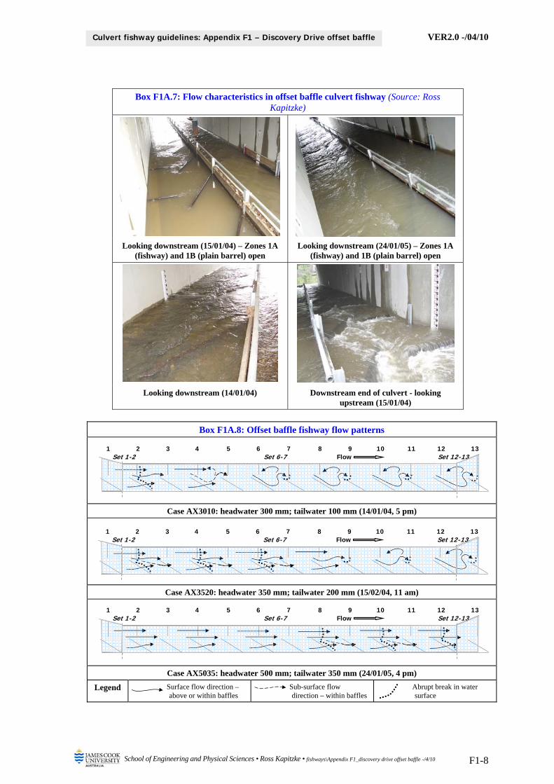
VER2.0 -/04/10
School of Engineering and Physical Sciences • Ross Kapitzke • fishways\Appendix F1_discovery drive offset baffle -/4/10 F1-8
Culvert fishway guidelines: Appendix F1 – Discovery Drive offset baffle
Box F1A.7: Flow characteristics in offset baffle culvert fishway (Source: Ross Kapitzke)
Looking downstream (15/01/04) – Zones 1A (fishway) and 1B (plain barrel) open
Looking downstream (24/01/05) – Zones 1A (fishway) and 1B (plain barrel) open
Looking downstream (14/01/04) Downstream end of culvert - looking upstream (15/01/04)
Box F1A.8: Offset baffle fishway flow patterns
Case AX3010: headwater 300 mm; tailwater 100 mm (14/01/04, 5 pm)
Case AX3520: headwater 350 mm; tailwater 200 mm (15/02/04, 11 am)
Case AX5035: headwater 500 mm; tailwater 350 mm (24/01/05, 4 pm)
Legend Surface flow direction –above or within baffles
Sub-surface flow direction – within baffles
Abrupt break in water surface
Set 12-13Set 1-2 2 3 4 5 6 7 8 9 101 11 12 13
Set 6-7 Flow
Set 12-13Set 1-2 2 3 4 5 6 7 8 9 101 11 12 13
Set 6-7 Flow
Set 12-13Set 1-2 2 3 4 5 6 7 8 9 101 11 12 13
Set 6-7 Flow
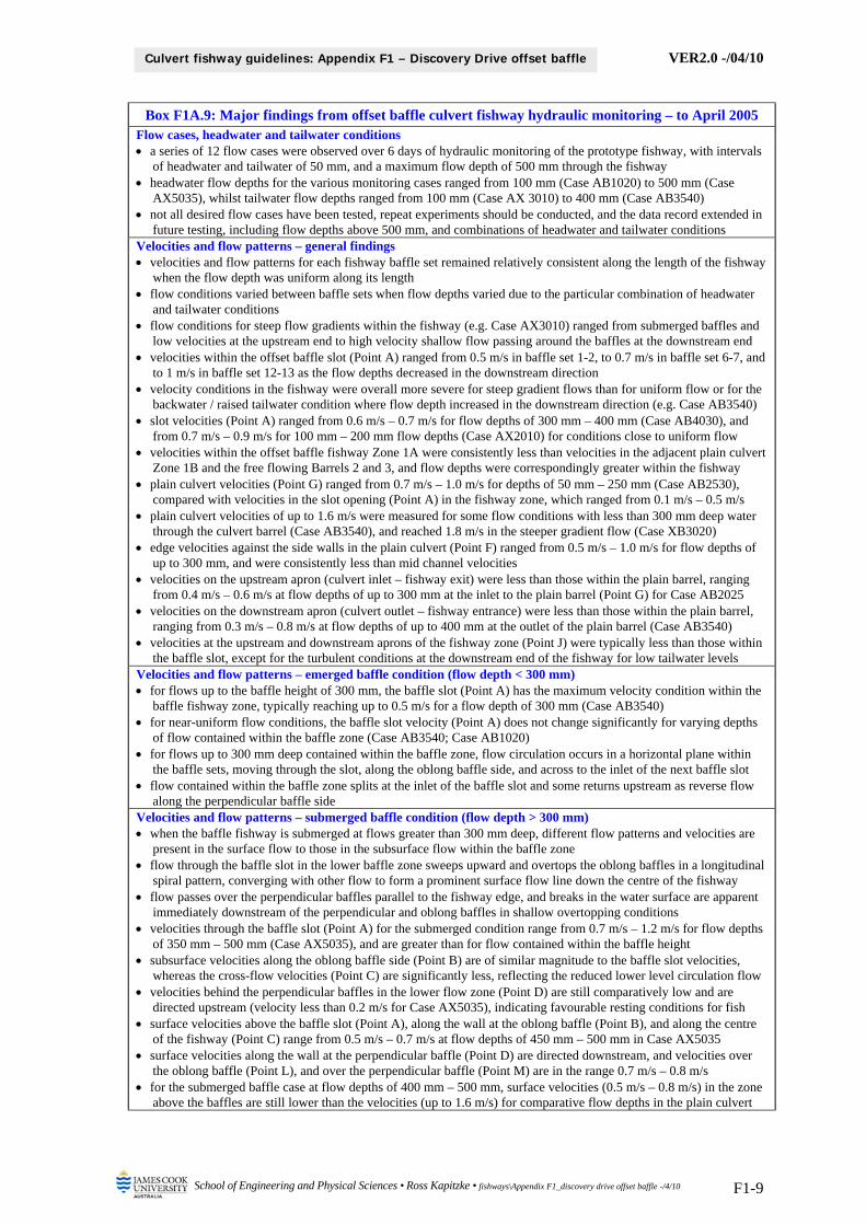
VER2.0 -/04/10
School of Engineering and Physical Sciences • Ross Kapitzke • fishways\Appendix F1_discovery drive offset baffle -/4/10 F1-9
Culvert fishway guidelines: Appendix F1 – Discovery Drive offset baffle
Box F1A.9: Major findings from offset baffle culvert fishway hydraulic monitoring – to April 2005 Flow cases, headwater and tailwater conditions a series of 12 flow cases were observed over 6 days of hydraulic monitoring of the prototype fishway, with intervals
of headwater and tailwater of 50 mm, and a maximum flow depth of 500 mm through the fishway headwater flow depths for the various monitoring cases ranged from 100 mm (Case AB1020) to 500 mm (Case
AX5035), whilst tailwater flow depths ranged from 100 mm (Case AX 3010) to 400 mm (Case AB3540) not all desired flow cases have been tested, repeat experiments should be conducted, and the data record extended in
future testing, including flow depths above 500 mm, and combinations of headwater and tailwater conditions Velocities and flow patterns – general findings velocities and flow patterns for each fishway baffle set remained relatively consistent along the length of the fishway
when the flow depth was uniform along its length flow conditions varied between baffle sets when flow depths varied due to the particular combination of headwater
and tailwater conditions flow conditions for steep flow gradients within the fishway (e.g. Case AX3010) ranged from submerged baffles and
low velocities at the upstream end to high velocity shallow flow passing around the baffles at the downstream end velocities within the offset baffle slot (Point A) ranged from 0.5 m/s in baffle set 1-2, to 0.7 m/s in baffle set 6-7, and
to 1 m/s in baffle set 12-13 as the flow depths decreased in the downstream direction velocity conditions in the fishway were overall more severe for steep gradient flows than for uniform flow or for the
backwater / raised tailwater condition where flow depth increased in the downstream direction (e.g. Case AB3540) slot velocities (Point A) ranged from 0.6 m/s – 0.7 m/s for flow depths of 300 mm – 400 mm (Case AB4030), and
from 0.7 m/s – 0.9 m/s for 100 mm – 200 mm flow depths (Case AX2010) for conditions close to uniform flow velocities within the offset baffle fishway Zone 1A were consistently less than velocities in the adjacent plain culvert
Zone 1B and the free flowing Barrels 2 and 3, and flow depths were correspondingly greater within the fishway plain culvert velocities (Point G) ranged from 0.7 m/s – 1.0 m/s for depths of 50 mm – 250 mm (Case AB2530),
compared with velocities in the slot opening (Point A) in the fishway zone, which ranged from 0.1 m/s – 0.5 m/s plain culvert velocities of up to 1.6 m/s were measured for some flow conditions with less than 300 mm deep water
through the culvert barrel (Case AB3540), and reached 1.8 m/s in the steeper gradient flow (Case XB3020) edge velocities against the side walls in the plain culvert (Point F) ranged from 0.5 m/s – 1.0 m/s for flow depths of
up to 300 mm, and were consistently less than mid channel velocities velocities on the upstream apron (culvert inlet – fishway exit) were less than those within the plain barrel, ranging
from 0.4 m/s – 0.6 m/s at flow depths of up to 300 mm at the inlet to the plain barrel (Point G) for Case AB2025 velocities on the downstream apron (culvert outlet – fishway entrance) were less than those within the plain barrel,
ranging from 0.3 m/s – 0.8 m/s at flow depths of up to 400 mm at the outlet of the plain barrel (Case AB3540) velocities at the upstream and downstream aprons of the fishway zone (Point J) were typically less than those within
the baffle slot, except for the turbulent conditions at the downstream end of the fishway for low tailwater levels Velocities and flow patterns – emerged baffle condition (flow depth < 300 mm) for flows up to the baffle height of 300 mm, the baffle slot (Point A) has the maximum velocity condition within the
baffle fishway zone, typically reaching up to 0.5 m/s for a flow depth of 300 mm (Case AB3540) for near-uniform flow conditions, the baffle slot velocity (Point A) does not change significantly for varying depths
of flow contained within the baffle zone (Case AB3540; Case AB1020) for flows up to 300 mm deep contained within the baffle zone, flow circulation occurs in a horizontal plane within
the baffle sets, moving through the slot, along the oblong baffle side, and across to the inlet of the next baffle slot flow contained within the baffle zone splits at the inlet of the baffle slot and some returns upstream as reverse flow
along the perpendicular baffle side Velocities and flow patterns – submerged baffle condition (flow depth > 300 mm) when the baffle fishway is submerged at flows greater than 300 mm deep, different flow patterns and velocities are
present in the surface flow to those in the subsurface flow within the baffle zone flow through the baffle slot in the lower baffle zone sweeps upward and overtops the oblong baffles in a longitudinal
spiral pattern, converging with other flow to form a prominent surface flow line down the centre of the fishway flow passes over the perpendicular baffles parallel to the fishway edge, and breaks in the water surface are apparent
immediately downstream of the perpendicular and oblong baffles in shallow overtopping conditions velocities through the baffle slot (Point A) for the submerged condition range from 0.7 m/s – 1.2 m/s for flow depths
of 350 mm – 500 mm (Case AX5035), and are greater than for flow contained within the baffle height subsurface velocities along the oblong baffle side (Point B) are of similar magnitude to the baffle slot velocities,
whereas the cross-flow velocities (Point C) are significantly less, reflecting the reduced lower level circulation flow velocities behind the perpendicular baffles in the lower flow zone (Point D) are still comparatively low and are
directed upstream (velocity less than 0.2 m/s for Case AX5035), indicating favourable resting conditions for fish surface velocities above the baffle slot (Point A), along the wall at the oblong baffle (Point B), and along the centre
of the fishway (Point C) range from 0.5 m/s – 0.7 m/s at flow depths of 450 mm – 500 mm in Case AX5035 surface velocities along the wall at the perpendicular baffle (Point D) are directed downstream, and velocities over
the oblong baffle (Point L), and over the perpendicular baffle (Point M) are in the range 0.7 m/s – 0.8 m/s for the submerged baffle case at flow depths of 400 mm – 500 mm, surface velocities (0.5 m/s – 0.8 m/s) in the zone
above the baffles are still lower than the velocities (up to 1.6 m/s) for comparative flow depths in the plain culvert
VER2.0 -/04/10
School of Engineering and Physical Sciences • Ross Kapitzke • fishways\Appendix F1_discovery drive offset baffle -/4/10 F1-10
Culvert fishway guidelines: Appendix F1 – Discovery Drive offset baffle
3 PROTOTYPE OFFSET BAFFLE FISHWAY BIOLOGICAL MONITORING
Biological monitoring at the prototype fishway devices and in adjoining reaches of University Creek provides an opportunity to understand fish passage characteristics of the culvert fishways, and movement capabilities of the various fish species under volitional swimming conditions. Biological monitoring was undertaken in conjunction with the hydraulic monitoring in order to correlate biological and hydraulic performance characteristics and to provide an integrated evaluation of the fishway.
Biological monitoring was performed by conducting visual observations, and using various fish trapping and netting techniques. The intention of the biological monitoring was to assess the effectiveness and performance of the fishway by determining the species of fish, the number of fish (abundance) and the size of fish using the fishway and passing the culvert barrier. Although limited opportunity has been available during monitoring events to date, fish swimming capabilities in particular fishway or plain culvert zones, and the effectiveness of the fishway installation in facilitating fish passage through the culvert can also be determined.
The aims of the biological field monitoring of the prototype and in the stream were to:
examine and measure fish abundance, diversity and migration success within the prototype fishway for a range of flow conditions and discharges
examine and measure fish behaviour, swimming ability, preferred pathways and resting areas of fish within the prototype fishway for a range of flow conditions and discharges
integrate biological prototype monitoring with biological field monitoring in adjoining stream reaches, biological laboratory / field testing, and associated desktop studies
integrate biological monitoring and evaluation activities with hydraulic monitoring and other studies
contribute to evaluation of the prototype culvert fishway and to determination of design parameters for other culvert fishway facilities.
follow operational and safety procedures for access and monitoring of the prototype facility
3.1 Biological monitoring equipment and methods
Surveys of fish populations and movements in the creek were undertaken using a 4 m long (5 mm mesh) seine net and a 1 m2 dip net, by direct surface observation (aided by binoculars), and by underwater observation using a face mask and snorkel (Box F1A.10). Visibility in the water was generally adequate to allow direct observations of fish movement through the culvert barrels and fishway in shallow flows, and this method was used to observe fish species type, fish abundance and movement characteristics from within the culvert and fishway sections and from the culvert headwalls above the fishway entrance and exits.
The performance of the fishway in comparison to other sections of the culvert was measured in terms of the net upstream movement of fish (number of fish exiting the upstream end of the culvert minus the number of fish moving downstream into the culvert) over a series of monitoring events of 30 – 60 minutes duration. The Plotosid catfish were the principal species passing through the fishway. All other fish were referred to as “small fish”, including Agassiz’s glassperch and Eastern Queensland rainbowfish, as well as juveniles and sub-adults of medium to larger-sized species, such as Banded grunter, Spangled perch and Mozambique mouthbrooder.

VER2.0 -/04/10
School of Engineering and Physical Sciences • Ross Kapitzke • fishways\Appendix F1_discovery drive offset baffle -/4/10 F1-11
Culvert fishway guidelines: Appendix F1 – Discovery Drive offset baffle
Box F1A.10: Biological monitoring of culvert fishway (Source: Ross Kapitzke)
Seine netting downstream of culvert (14/01/04)
Dip netting upstream of fishway (14/01/04)
3.2 Biological monitoring results for 2004 and 2005
Biological monitoring of the Discovery Drive prototype fishway was undertaken in conjunction with hydraulic monitoring during the flow events on 13-16 January 2004, 12-15 February 2004, and 24-25 January 2005 (Webb 2004; Webb 2005). Previous surveys (2003) of the fish community in University Creek revealed a total of 13 native and 4 non-native (exotic) species (Webb 2003). This included two species of catfish, the Black catfish Neosilurus ater, and Hyrtl’s tandan Neosilurus hyrtlii, other native species such as Eastern rainbowfish, Fly-specked hardyhead, Purple-spotted gudgeon and Agassiz’s glass perch, and two species of non-native fish (Mozambique mouthbrooder and Mosquitofish).
During the 2004 and 2005 monitoring events, the maximum number of native species present was 10 species in January 2004. Of the 10 native fish species observed immediately downstream of the Discovery Drive crossing / fishway during the 2004 survey period, all but 2 species were also observed upstream of the crossing, indicating successful passage through the culvert / fishway. During the January 2005 event, a total of 7 fish species were observed upstream. Upstream fish movement and the “supply” of fish to the Discovery Drive culvert site were, however, restricted during the January 2004 event as a result of a temporary blockage at a downstream road crossing.
The results of fish movement through the various fishway and culvert zones for the 2004 and 2005 events are presented in Box F1A.11 for the Black catfish and in Box F1A.12 for the small fish species. Photographic records of flow characteristics and fish movement within the fishway are shown in Box F1A.13. The number of catfish passing through the fishway or the culvert barrels is related to the hydraulic characteristics (e.g. water depth, velocity, flow patterns), as well as the number of fish migrating upstream at any time. The “supply” of catfish at the fishway, although restricted during the 2004 events, was greatest at shallow flow depths. Apart from limited data obtained in January 2005, no objective observations of capacity to move through the fishway were made for flow depths above 300 mm due both to the short period of time at these flow conditions, and the lack of fish present.
Box F1A.11: Net movement of Black catfish through fishway and culvert for flow events January 2004, February 2004, January 2005
Biological monitoring
event
Fishway / culvert flows; water depth; hydr. monitoring flow case (see Box F1A.5, F1A.6)
Net upstream passage of Black Catfish through fishway and culvert barrels (Source: Webb 2004; Webb 2005)
Barrel 3 Barrel 2 Zone 1B Zone 1A
January 2004 – 15/01/04 1319-1419 Zone 1A & 1B flowing; Barrel 2 &
3 closed; HW = 200 x x 0 +94
1450-1520 Zone 1B, Barrel 2 flowing; Zone 1A, Barrel 3 closed; HW = 100
x -49 -18 x

VER2.0 -/04/10
School of Engineering and Physical Sciences • Ross Kapitzke • fishways\Appendix F1_discovery drive offset baffle -/4/10 F1-12
Culvert fishway guidelines: Appendix F1 – Discovery Drive offset baffle
Box F1A.11: Net movement of Black catfish through fishway and culvert for flow events January 2004, February 2004, January 2005
Biological monitoring
event
Fishway / culvert flows; water depth; hydr. monitoring flow case (see Box F1A.5, F1A.6)
Net upstream passage of Black Catfish through fishway and culvert barrels (Source: Webb 2004; Webb 2005)
Barrel 3 Barrel 2 Zone 1B Zone 1A
1522-1622 Zone 1B flowing; Zone 1A, Barrel 2 & 3 closed; HW = 150
x x -5 x
1630-1700 Zone 1A & 1B flowing; Barrel 2 & 3 closed; HW = 150
x x -6 +67
1700-1800 Zone 1A flowing; Zone 1B, Barrel 2 & 3 closed; HW = 250
x x x +20
January 2004 – 16/01/04 1600-1700 Zone 1A & 1B, Barrel 2 & 3
flowing; HW = 250 1 -2 -2 +12
January 2004 – 17/01/04 0910-1010 Zone 1A & 1B, Barrel 2 & 3
flowing; HW = 150 0 -6 -11 +7
1140-1240 0 0 0 0
February 2004 – 12/02/04 1710-1740 Zone 1A & 1B, Barrel 2 flowing;
Barrel 3 closed; HW = 200 x +7 +4 +80
1755-1825 Zone 1A, Barrel 2 flowing; Zone 1B, Barrel 3 closed; HW = 200
x 0 x +26
1835-1855 Zone 1A & 1B, Barrel 2 flowing; Barrel 3 closed; HW = 200
x +5 0 +40
January 2005 – 22/01/05 1600-1630 Zone 1A & 1B, Barrel 2 & 3
flowing; HW = 150 +1 +5 0 +13
1630-1700 0 +2 0 +15
1700-1730 0 +3 -1 +11
January 2005 – 23/01/05 0730-0800 Zone 1A & 1B, Barrel 2 & 3
flowing; HW = 200 +2 +8 -4 +22
0800-0830 +1 +10 -10 +25
0830-0900 0 -11 -23 +18
0900-0930 0 +18 -16 +28
January 2005 – 24/01/05 1500-1530 Zone 1A flowing; Zone 1B, Barrel
2 & 3 closed; HW = 500; AX5035 x x x +4
1530-1600 x x x +9
1655-1725 x x x +8
1725-1755 Zone 1B flowing; Zone 1A, Barrel 2 & 3 closed; HW = 250; XB3020
x x -12 x
1755-1825 Zone 1B, Barrel 2 & 3 flowing; Zone 1A closed; HW = 200
0 +3 +4 x
January 2005 – 25/01/05 0815-0845 Zone 1A & 1B, Barrel 2 & 3
flowing; HW = 100 0 -8 -10 -10
0845-0915 0 -18 -2 -3
0925-0955 0 -24 -4 -2
1005-1035 Zone 1A & 1B flowing; Barrel 2 & 3 closed; HW = 150
x x -7 -11
1035-1105 x x -9 -4
1105-1135 x x -9 -3

VER2.0 -/04/10
School of Engineering and Physical Sciences • Ross Kapitzke • fishways\Appendix F1_discovery drive offset baffle -/4/10 F1-13
Culvert fishway guidelines: Appendix F1 – Discovery Drive offset baffle
Box F1A.12: Net movement of small fish through fishway and culvert for flow event January 2004
Biological monitoring
event
Fishway / culvert flows; water depth; hydraulic monitoring flow case (see Box 6.14, 6.15)
Net upstream passage small fish through fishway and culvert barrels (Source: Webb 2004)
Barrel 3 Barrel 2 Zone 1B Zone 1A
January 2004 – 15/01/04 1700-1800 Zone 1A flowing; Zone 1B, Barrel
2 & 3 closed; HW = 250 x x x +1
January 2004 – 16/01/04 1600-1700 Zone 1A & 1B, Barrel 2 & 3
flowing; HW = 250 0 0 0 +5
January 2004 – 17/01/04 0910-1010 Zone 1A & 1B, Barrel 2 & 3
flowing; HW = 150 +2 +13 -4 +50
1140-1240 0 -7 0 +24
Box F1A.13: Flow characteristics and movement of Plotosid catfish through the offset baffle fishway (Source: Ross Kapitzke)
Resting downstream of perpendicular baffle – flow direction left to right (13/01/04)
Passing upstream through baffle slot – flow direction right to left (13/01/04)
3.3 Summary of findings – biological monitoring of prototype offset baffle
Major outcomes and findings from the biological monitoring of the prototype offset baffle fishway for 2003/04/05 are presented in Box F1A.14. The results indicate that the prototype offset baffle fishway is effective in facilitating upstream migration of large Black catfish as well as small to medium sized fish species. Considering the prevailing low flow conditions and taking into account the effects of downstream obstructions to fish movement, the monitoring results also indicate that a larger number of fish species than those recorded during the flow events may be expected to utilise University Creek under more favourable conditions.
Further experimentation and monitoring will increase understanding of fishway biological performance under a range of conditions, including flows in excess of 500 mm deep, and various combinations of headwater and tailwater conditions. The effects of attraction flows should be investigated, and joint hydraulic and biological monitoring and observations of fish movement for various velocity and flow conditions in the fishway and culvert zones are important to assist in determining the limiting conditions for fish movement through the fishway, and to understand movement behaviour of the various species in terms of flow path, delay time or motivation.
Box F1A.14: Major outcomes and findings from biological monitoring – to April 2005 Flow cases, fish monitoring methods and general fish movement conditions a series of fish surveys and biological monitoring have been undertaken over 3 flow events in the creek during
2004/05, focusing on the lower creek reaches and the performance of the Discovery Drive prototype fishway fish movement at the Discovery Drive site during 2004 has been confounded by delays caused by downstream
barriers, which blocked and delayed upstream migration performance of the fishway / culvert was measured in terms of the net movement of catfish and smaller species
(number of fish exiting upstream of the culvert minus the number of fish moving downstream into the culvert)
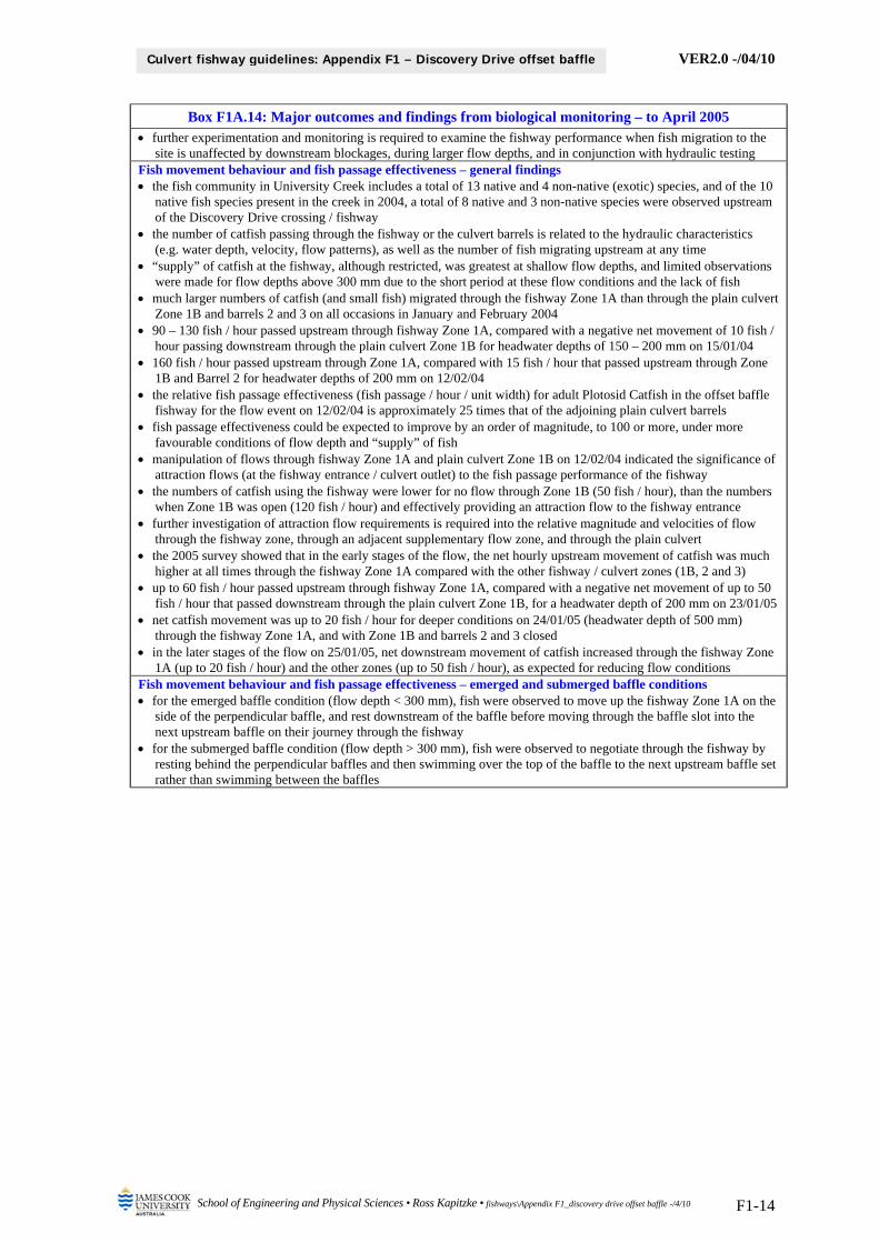
VER2.0 -/04/10
School of Engineering and Physical Sciences • Ross Kapitzke • fishways\Appendix F1_discovery drive offset baffle -/4/10 F1-14
Culvert fishway guidelines: Appendix F1 – Discovery Drive offset baffle
Box F1A.14: Major outcomes and findings from biological monitoring – to April 2005 further experimentation and monitoring is required to examine the fishway performance when fish migration to the
site is unaffected by downstream blockages, during larger flow depths, and in conjunction with hydraulic testing Fish movement behaviour and fish passage effectiveness – general findings the fish community in University Creek includes a total of 13 native and 4 non-native (exotic) species, and of the 10
native fish species present in the creek in 2004, a total of 8 native and 3 non-native species were observed upstream of the Discovery Drive crossing / fishway
the number of catfish passing through the fishway or the culvert barrels is related to the hydraulic characteristics (e.g. water depth, velocity, flow patterns), as well as the number of fish migrating upstream at any time
“supply” of catfish at the fishway, although restricted, was greatest at shallow flow depths, and limited observations were made for flow depths above 300 mm due to the short period at these flow conditions and the lack of fish
much larger numbers of catfish (and small fish) migrated through the fishway Zone 1A than through the plain culvert Zone 1B and barrels 2 and 3 on all occasions in January and February 2004
90 – 130 fish / hour passed upstream through fishway Zone 1A, compared with a negative net movement of 10 fish / hour passing downstream through the plain culvert Zone 1B for headwater depths of 150 – 200 mm on 15/01/04
160 fish / hour passed upstream through Zone 1A, compared with 15 fish / hour that passed upstream through Zone 1B and Barrel 2 for headwater depths of 200 mm on 12/02/04
the relative fish passage effectiveness (fish passage / hour / unit width) for adult Plotosid Catfish in the offset baffle fishway for the flow event on 12/02/04 is approximately 25 times that of the adjoining plain culvert barrels
fish passage effectiveness could be expected to improve by an order of magnitude, to 100 or more, under more favourable conditions of flow depth and “supply” of fish
manipulation of flows through fishway Zone 1A and plain culvert Zone 1B on 12/02/04 indicated the significance of attraction flows (at the fishway entrance / culvert outlet) to the fish passage performance of the fishway
the numbers of catfish using the fishway were lower for no flow through Zone 1B (50 fish / hour), than the numbers when Zone 1B was open (120 fish / hour) and effectively providing an attraction flow to the fishway entrance
further investigation of attraction flow requirements is required into the relative magnitude and velocities of flow through the fishway zone, through an adjacent supplementary flow zone, and through the plain culvert
the 2005 survey showed that in the early stages of the flow, the net hourly upstream movement of catfish was much higher at all times through the fishway Zone 1A compared with the other fishway / culvert zones (1B, 2 and 3)
up to 60 fish / hour passed upstream through fishway Zone 1A, compared with a negative net movement of up to 50 fish / hour that passed downstream through the plain culvert Zone 1B, for a headwater depth of 200 mm on 23/01/05
net catfish movement was up to 20 fish / hour for deeper conditions on 24/01/05 (headwater depth of 500 mm) through the fishway Zone 1A, and with Zone 1B and barrels 2 and 3 closed
in the later stages of the flow on 25/01/05, net downstream movement of catfish increased through the fishway Zone 1A (up to 20 fish / hour) and the other zones (up to 50 fish / hour), as expected for reducing flow conditions
Fish movement behaviour and fish passage effectiveness – emerged and submerged baffle conditions for the emerged baffle condition (flow depth < 300 mm), fish were observed to move up the fishway Zone 1A on the
side of the perpendicular baffle, and rest downstream of the baffle before moving through the baffle slot into the next upstream baffle on their journey through the fishway
for the submerged baffle condition (flow depth > 300 mm), fish were observed to negotiate through the fishway by resting behind the perpendicular baffles and then swimming over the top of the baffle to the next upstream baffle set rather than swimming between the baffles

VER2.0 -/04/10
School of Engineering and Physical Sciences • Ross Kapitzke • fishways\Appendix F1_discovery drive offset baffle -/4/10 F1-15
Culvert fishway guidelines: Appendix F1 – Discovery Drive offset baffle
4 HYDRAULIC LABORATORY MODELLING
Hydraulic laboratory modelling has been used in conjunction with the Discovery Drive prototype in the development and testing of the offset baffle fishway design for box culverts. Laboratory modelling allows ready visualisation and measurement of a range of fishway configurations and sizes. Scale models of the box culvert and prototype fishway are established in the flume, the hydraulic characteristics of the various culvert fishway structures are examined, and laws of similitude are applied to transfer values between model and prototype.
This section describes hydraulic laboratory modelling for the offset baffle fishway for box culverts undertaken at the hydraulic model facility at JCU School of Engineering. The major outcomes and findings for the work until 2006 are summarised, including flow patterns and velocities for a range of flow depths in the fishway (Stewart 2003; Ferrando 2006). More recent modelling has examined variations of hydraulic characteristics with culvert slope (Powell 2007).
4.1 Hydraulic laboratory modelling equipment and methods
A scale model of the box culvert, 360 mm wide and 2200 mm long, and fabricated from Perspex, is fitted within the laboratory flume. Fishway models at 1:5 scale, fabricated from Perspex and fitted within the culvert model on light aluminium frames, correspond to a fishway cell width of 1800 mm in the culvert. Slope adjustment of the culvert fishway can be achieved through placement of blocks under the model, and by clamping sheets of rubber to the box culvert inlet and outlet headwalls to seal the model within the flume as the culvert slope is varied.
Velocity and depth measurements within the culvert / fishway are undertaken through the open top of the box culvert model, and the transparent sides of the culvert and fishway models assist with flow visualisation. Visual, photo and video observation are used to study flow patterns and turbulence, with the assistance of die tracers and other visualisation techniques. Velocity profiles for various water depths and discharges in the fishway models are measured using the Swoffer 3000 miniature propeller current meter, and water depth is measured with depth gauges.
The hydraulic model configuration simulates open-channel flow conditions, typical of culvert fishway facilities at low to medium flow. The uniform flow condition is sought, where the water surface slope is parallel to the culvert bed through most of the fishway length, and the observed conditions in the model are unaffected by end effects such as headwater or tailwater levels that differ from normal culvert flow levels. Data representative of uniform flow are obtained from baffle sets in the mid section of the fishway model, where flow is fully established.
4.2 Results from hydraulic laboratory modelling
The most extensive data on flow patterns, velocity, depth and discharge characteristics for the offset baffle fishway model has been obtained for a culvert slope of 1.0 % (Stewart 2003; Ferrando 2006). The testing involved a series of flow cases at flow depths of one, two and three standard baffle heights, with flow patterns and velocities recorded within each of the flow layers for the range of flow depths / discharges. Flow pattern, velocity, depth and discharge observations and measurements were compiled and evaluated as follows:
surface and subsurface flow patterns through culvert and fishway baffles sets, showing flow continuity and streamlines, recirculation, zones of high or low velocity and/or turbulence
velocity variation with flow depth / discharge at critical points within baffle sets in the lower flow layer (one standard baffle height)
velocity variation with flow layers (one, two and three standard baffle heights) at critical points within baffle sets for the maximum flow case (three baffle heights flow depth)
variations in dimensionless discharge and dimensionless velocity at key points in the culvert with dimensionless flow depth

VER2.0 -/04/10
School of Engineering and Physical Sciences • Ross Kapitzke • fishways\Appendix F1_discovery drive offset baffle -/4/10 F1-16
Culvert fishway guidelines: Appendix F1 – Discovery Drive offset baffle
comparison between hydraulic characteristics of various fishway designs, the plain culvert, and prototype fishway facilities (tested in the field to a maximum flow depth of 500 mm)
The effects of the offset baffle fishway on flow circulation and shelter / flow retardance within the various flow layers are evident from flow visualisation images (Boxes F1A.15 – F1A.17). Flow patterns and the relative magnitude of velocities within the flow layers (Box F1A.17) include observations within lower flow layer 1 for the range of flow depths / discharges, and within flow layers 1, 2 and 3 for the maximum flow depth / discharge case. Comparisons can be made with data for the plain culvert and for the prototype fishway (Boxes F1A.5 – F1A.8), which is available for flow depths to slightly greater than one standard baffle height.
Box F1A.15: Flow visualisation for the offset baffle fishway (Source: Stewart 2003)
Flow direction vanes showing flow pattern in the lower flow layer within the baffle sets
Graphical simulation of flow direction and magnitude obtained from fishway model
Box F1A.16: Offset baffle fishway flow patterns – 1.0 % slope (Source: Model testing –
Toni Ferrando; Photo – Ross Kapitzke)
One standard baffle height flow depth: Time step 1; dye pattern showing flow circulation
within baffle field (06/06/06)
One standard baffle height flow depth: Time step 2; dye pattern showing shelter / flow retardence within baffle field (06/06/06)
Three standard baffle height flow depth: Time step 1; dye pattern showing flow
concentration in fishway centre (06/06/06)
Three standard baffle height flow depth: Time step 2; showing spiralling flow on right hand oblong baffle side of fishway (06/06/06)
Flow

VER2.0 -/04/10
School of Engineering and Physical Sciences • Ross Kapitzke • fishways\Appendix F1_discovery drive offset baffle -/4/10 F1-17
Culvert fishway guidelines: Appendix F1 – Discovery Drive offset baffle
Box F1A.17: Flow patterns and velocities in flow layers for various flow depths and discharges (After: Stewart 2003)
Low flow – depth 300 mm (1 baffle height) Medium flow – depth 600 mm (2 baffle heights) High flow – depth 900 mm (3 baffle heights)
Bottom flow layer < 300 mm
300 mm < Middle flow layer < 600 mm
600 mm < Top flow layer < 900 mm

VER2.0 -/04/10
School of Engineering and Physical Sciences • Ross Kapitzke • fishways\Appendix F1_discovery drive offset baffle -/4/10 F1-18
Culvert fishway guidelines: Appendix F1 – Discovery Drive offset baffle
4.3 Summary of findings – offset baffle hydraulic laboratory modelling
Major outcomes and findings from the hydraulic laboratory modelling of the offset baffle fishway at 1.0 % slope are presented in Box F1A.18. This includes data for flow depths through the fishway of up to 3 standard baffle heights, and comparisons where appropriate with results from the Discovery Drive prototype offset baffle fishway (see Section 2.3 of this appendix F1).
Box F1A.18: Major outcomes and findings from hydraulic laboratory modeling of offset baffle fishway for box culverts (model results after Stewart 2003 and Ferrando 2006; prototype data from field
testing – see Section 2.3) Flow cases, fishway designs, flow depths and formulae
testing for the offset baffle fishway and the plain culvert barrel included flows Q1 (one baffle height), Q2 (two baffle heights), Q3 (three baffle heights) for culvert slope of 1.0%
all velocities expressed in equivalent prototype values, which are converted using the following: 1
5mp vv where
vp = velocity in prototype fishway; vm = velocity in model fishway
Flow characteristics of offset baffle fishway – emerged baffle condition (flow depth < 300 mm) for emerged flow conditions, with flow depth at or below one standard baffle height, the baffles have the effect of
directing flow through the baffle slots and circulating the flow in a horizontal plane within the baffle sets flow continuity is provided within and between the baffle sets, with flow streamlines passing alongside the oblong
baffles and linking between baffle slots, and flow recirculation occurring downstream of the perpendicular baffles maximum velocities occur through the baffle slot in the lower flow zone within the fishway, a backwater effect with
virtually still water is produced on the downstream side of the perpendicular baffles, and negative (upstream) velocities are produced in the recirculation zone downstream of the perpendicular baffles
flow patterns and velocities in the emerged flow condition are similar to those observed in the prototype testing Flow characteristics of offset baffle fishway – submerged baffle condition (flow depth > 300 mm) for submerged flow conditions, with flow depth greater than one standard baffle height, spiraling flow on the culvert
edge is directed transversely over the oblong baffle toward the centre of the fishway, and the overall flow direction changes to be more streamlined longitudinally in the horizontal plane
flow in the lower zone (up to the top of the baffles) is directed up and over the diagonal baffle, with the transverse flow direction most pronounced in the zone immediately above the baffles, and flow in the upper zone closest to being longitudinally streamlined parallel to the culvert walls
spiraling flow over the oblong baffles produces turbulent flow conditions along the culvert wall and concentrates flow into the centre of the fishway
velocities in the lower flow zone within the fishway increase with increased submergence of the fishway, but a sheltering effect is maintained behind the perpendicular baffles within this lower flow zone
velocities in open channel sections in upper flow layers above the offset baffle structure are much greater than velocities in lower flow layers within the baffle structure
horizontal flow circulations in the lower flow zone are broken down with increased submergence of the fishway, and the velocity field alongside and over the oblong baffles becomes more uniform in direction and larger in magnitude
flow patterns and velocities in the submerged flow condition are similar to those observed for limited testing in the prototype
Comparative hydraulic performance of offset baffle fishway and plain culvert the offset baffle fishway produces substantially lower velocity conditions through the baffle slot and in sheltered
flow areas in the lower flow zone within the fishway than occurs within a plain culvert lower velocity and sheltered flow zones are maintained in the offset baffle fishway for submerged flow conditions,
whereas velocities increase and no shelter is provided for increased flow in the plain culvert

VER2.0 -/04/10
School of Engineering and Physical Sciences • Ross Kapitzke • fishways\Appendix F1_discovery drive offset baffle -/4/10 F1-19
Culvert fishway guidelines: Appendix F1 – Discovery Drive offset baffle
5 BIBLIOGRAPHY Ferrando, T. 2006, Performance characteristics of offset baffle and corner baffle fishways for box culverts,
Bachelor of Engineering Thesis, James Cook University School of Engineering. Kapitzke, I.R. 2006a, Bruce Highway Corduroy Creek to Tully planning study Provisions for fish passage
– Road corridor scale Assessment Task 1A, report to Maunsell Australia and Department of Main Roads. Kapitzke, I.R. 2006b, Discovery Drive offset baffle fishway for box culverts (Prototype Fishway # 1): Case
study project design and prototype monitoring report to April 2005, report to Dept of Main Roads. Kapitzke, I.R. 2006c, Douglas Arterial Project rock ramp fishway for open channels (Prototype Fishway #
2): Case study project design and prototype monitoring report to April 2005, report to Dept Main Roads. Kapitzke, I.R. 2007a, Bruce Highway Corduroy Creek to Tully High School Provisions for fish passage –
Preliminary Design Assessment Tasks 1B and 2, report to Maunsell Australia and Dept of Main Roads. Kapitzke, I.R. 2007b, Discovery Drive corner baffle fishway for box culverts (Prototype Fishway # 4):
Case study project design and prototype monitoring report to April 2006, report to Dept of Main Roads. Kapitzke, I.R. 2007c, Solander Road pipe culvert fishway (Prototype Fishway # 3): Case study project
design and prototype monitoring report to April 2006, report to Department of Main Roads. McKinley, W.R. and R.D. Webb. 1956. "A proposed correction of migratory fish problems at box
culverts". Washington Department of Fisheries Fish Research Papers 1(4): 33-45, Olympia, WA. Powell, C. 2007, Design adaptations for offset baffle and corner baffle fishways for box culverts, Bachelor
of Engineering Thesis, James Cook University School of Engineering. Stewart, J. 2003, The hydraulic characteristics of the offset baffle fishway design for box culverts, Honours
Thesis, James Cook University School of Engineering. Webb, A.C. 2003, Fish survey of Campus Creek February – April 2003, report prepared by James Cook
University Department of Zoology. Webb, A.C. 2004, Biomonitoring of the Campus Creek fishway project February 2004, report prepared by
James Cook University School of Tropical Biology. Webb, A.C. 2005, Campus Creek fishway project 05 Biomonitoring Report, report prepared by James
Cook University School of Tropical Biology.
Ross Kapitzke James Cook University School of Engineering and Physical Sciences April 2010 – VER2.0

VER2.0 -/04/10
Ross Kapitzke • JCU Engineering • DMR culvert fishway guidelines • fishways\F_baffle fishways for box culverts -/4/10
Culvert fishway guidelines: Part F – Baffle fishways for box culverts
APPENDIX F2 – DISCOVERY DRIVE PROTOTYPE CORNER “EL” BAFFLE FISHWAY

VER2.0 -/04/10
School of Engineering and Physical Sciences • Ross Kapitzke • fishways\Appendix F2_discovery drive corner EL baffle -/4/10 F2-i
Culvert fishway guidelines: Appendix F2 – Discovery Drive corner “EL” baffle
James Cook University School of Engineering and Physical Sciences Culvert Fishway Design Guidelines: Part F – Baffle Fishways for Box Culverts Appendix F2 – Discovery Drive Prototype Corner “EL” Baffle Fishway Contents
1 DISCOVERY DRIVE CORNER “EL” BAFFLE FISHWAY FACILITY 1
2 PROTOTYPE CORNER “EL” BAFFLE FISHWAY HYDRAULIC MONITORING 3
2.1 Hydraulic monitoring equipment and methods 3 2.2 Hydraulic monitoring results for 2006 5 2.3 Summary of findings – physical monitoring of prototype corner baffle 7
3 HYDRAULIC LABORATORY MODELLING 9 3.1 Results from hydraulic laboratory modelling 9 3.2 Summary of findings – corner “EL” baffle hydraulic laboratory modelling 12
4 BIBLIOGRAPHY 14
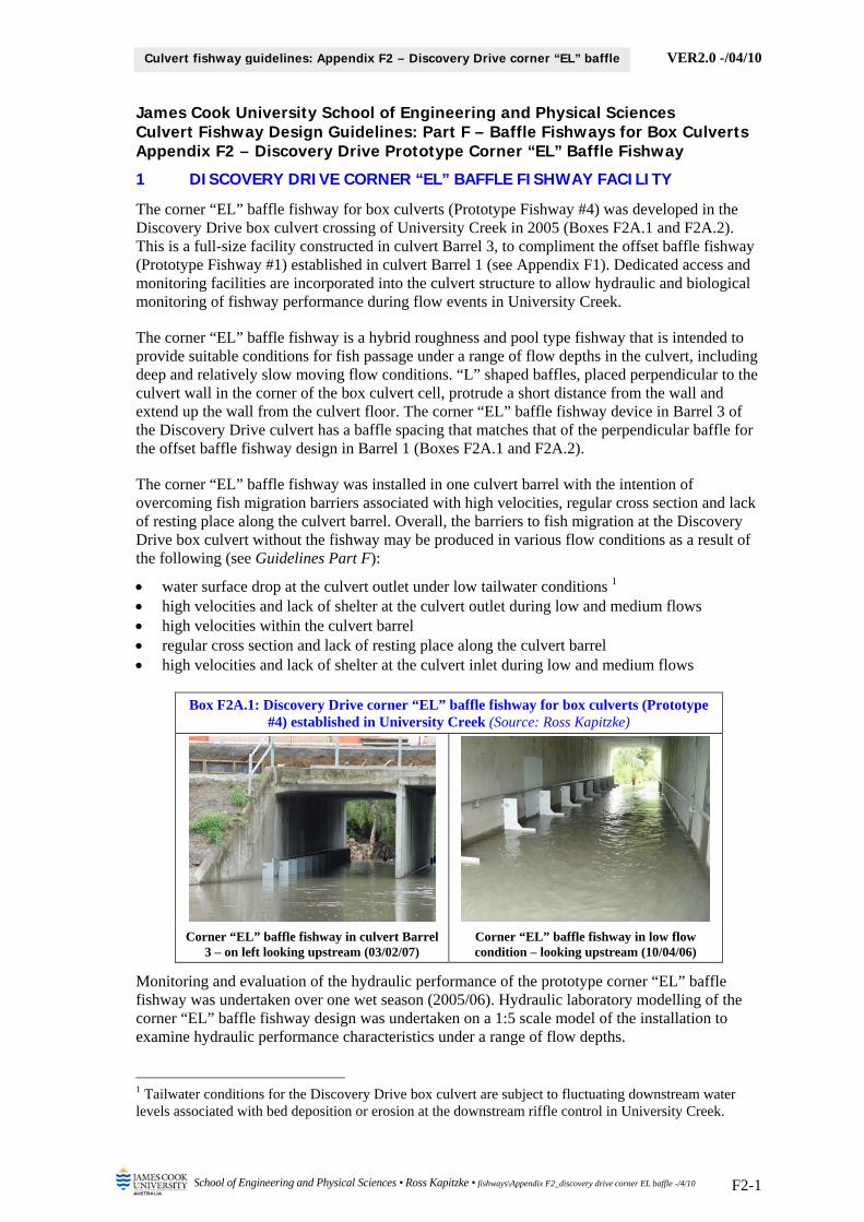
VER2.0 -/04/10
School of Engineering and Physical Sciences • Ross Kapitzke • fishways\Appendix F2_discovery drive corner EL baffle -/4/10 F2-1
Culvert fishway guidelines: Appendix F2 – Discovery Drive corner “EL” baffle
James Cook University School of Engineering and Physical Sciences Culvert Fishway Design Guidelines: Part F – Baffle Fishways for Box Culverts Appendix F2 – Discovery Drive Prototype Corner “EL” Baffle Fishway
1 DISCOVERY DRIVE CORNER “EL” BAFFLE FISHWAY FACILITY
The corner “EL” baffle fishway for box culverts (Prototype Fishway #4) was developed in the Discovery Drive box culvert crossing of University Creek in 2005 (Boxes F2A.1 and F2A.2). This is a full-size facility constructed in culvert Barrel 3, to compliment the offset baffle fishway (Prototype Fishway #1) established in culvert Barrel 1 (see Appendix F1). Dedicated access and monitoring facilities are incorporated into the culvert structure to allow hydraulic and biological monitoring of fishway performance during flow events in University Creek.
The corner “EL” baffle fishway is a hybrid roughness and pool type fishway that is intended to provide suitable conditions for fish passage under a range of flow depths in the culvert, including deep and relatively slow moving flow conditions. “L” shaped baffles, placed perpendicular to the culvert wall in the corner of the box culvert cell, protrude a short distance from the wall and extend up the wall from the culvert floor. The corner “EL” baffle fishway device in Barrel 3 of the Discovery Drive culvert has a baffle spacing that matches that of the perpendicular baffle for the offset baffle fishway design in Barrel 1 (Boxes F2A.1 and F2A.2).
The corner “EL” baffle fishway was installed in one culvert barrel with the intention of overcoming fish migration barriers associated with high velocities, regular cross section and lack of resting place along the culvert barrel. Overall, the barriers to fish migration at the Discovery Drive box culvert without the fishway may be produced in various flow conditions as a result of the following (see Guidelines Part F):
water surface drop at the culvert outlet under low tailwater conditions 1 high velocities and lack of shelter at the culvert outlet during low and medium flows high velocities within the culvert barrel regular cross section and lack of resting place along the culvert barrel high velocities and lack of shelter at the culvert inlet during low and medium flows
Box F2A.1: Discovery Drive corner “EL” baffle fishway for box culverts (Prototype #4) established in University Creek (Source: Ross Kapitzke)
Corner “EL” baffle fishway in culvert Barrel 3 – on left looking upstream (03/02/07)
Corner “EL” baffle fishway in low flow condition – looking upstream (10/04/06)
Monitoring and evaluation of the hydraulic performance of the prototype corner “EL” baffle fishway was undertaken over one wet season (2005/06). Hydraulic laboratory modelling of the corner “EL” baffle fishway design was undertaken on a 1:5 scale model of the installation to examine hydraulic performance characteristics under a range of flow depths.
1 Tailwater conditions for the Discovery Drive box culvert are subject to fluctuating downstream water levels associated with bed deposition or erosion at the downstream riffle control in University Creek.

VER2.0 -/04/10
School of Engineering and Physical Sciences • Ross Kapitzke • fishways\Appendix F2_discovery drive corner EL baffle -/4/10 F2-2
Culvert fishway guidelines: Appendix F2 – Discovery Drive corner “EL” baffle
The following sections describe the findings of field prototype and laboratory model testing, and evaluate the performance characteristics of the corner “EL” baffle fishway design. The material presented here is taken principally from the report Discovery Drive corner baffle fishway for box culverts (Prototype Fishway # 4): Case study project design and prototype monitoring report to April 2006 (Kapitzke 2007b).
Box F2A.2: Discovery Drive box culvert corner “EL” baffle fishway configuration
Discovery Drive 3-cell box culvert plan view – showing fishway zones and monitoring facilities 1
Discovery Drive culvert section showing fishway zones 1
Corner “EL” baffle fishway – Barrel 3 looking downstream 1
Corner “EL” baffle fishway in Barrel 3 – Plan View 1
Notes 1 This is a prototype facility in which the baffle fishway devices are constructed to suit adaptation and performance evaluation, and which includes provisions for monitoring and access that will not normally be incorporated into field installations of culvert fishway facilities
Access platforms and monitoring cage
Barrel 2
Barrel 1
Fishway Zone 1A – Offset Baffle
Flow
Fish fence
Fish fence
Barrel 3
Fishway Zone 1B – Plain culvert
Fishway Zone 3 – Corner BaffleNib wall
Fishway Zone 1A Offset Baffle
Barrel 2 Barrel 3
Hinged platform Handrails
Fishway Zone 3 Corner Baffle
Barrel 1
Box culvert corner block
400
Corner baffle
300
300
600
1 4 5 6 7 8 9 10 11 12 13 2 3
3600 1000 2000 22 000
700
1000 20001000 2000 1000
Flow

VER2.0 -/04/10
School of Engineering and Physical Sciences • Ross Kapitzke • fishways\Appendix F2_discovery drive corner EL baffle -/4/10 F2-3
Culvert fishway guidelines: Appendix F2 – Discovery Drive corner “EL” baffle
2 PROTOTYPE CORNER “EL” BAFFLE FISHWAY HYDRAULIC MONITORING
Field monitoring of the Discovery Drive corner “EL” baffle fishway (Prototype #4) was undertaken in conjunction with monitoring of the Discovery Drive offset baffle fishway (Prototype #1) and the Solander Road pipe culvert fishway (Prototype #3). This was part of an integrated monitoring, modelling and evaluation plan for the fishway that set out to evaluate performance in accordance with the design objectives for the facility. Hydraulic and biological monitoring studies of the prototype fishway within University Creek were used in conjunction with hydraulic laboratory modelling of fishway designs to confirm stream hydrology, culvert hydraulics, fish passage behaviour and the effects of culvert remediation works.
For the Discovery Drive corner “EL” baffle fishway, the field work included first level hydraulic monitoring in and adjacent to the fishway, and biological monitoring of the stream reaches adjoining the Discovery Drive and Solander Road crossings. No direct observations of fish movement through the corner “EL” baffle fishway, offset baffle fishway or plain culvert barrels were undertaken at the Discovery Drive culvert due to restricted opportunities during flow events in University Creek.
Physical monitoring of the prototype fishway examined the hydraulic characteristics of the fishway devices and the overall effectiveness of the facility, and included manipulation of flow conditions through the culvert to study hydraulic characteristics under varying conditions. The hydraulic monitoring used a flow meter to determine velocity measurements, and direct measurements, observations, photographs and video to examine water depths and flow profiles associated with the fishway and the culvert during periods of relevant flow. Water depths in the fishway were measured using a number of gauge boards attached to the culvert walls, and flow meter measurements were undertaken by access along the culvert floor during low level flows, subject to operational safety provisions. The effect of the fishway on flow velocities throughout the culvert was determined, and flow velocity patterns and profiles compiled to allow correlation with the theoretical and laboratory data obtained from desktop studies and hydraulic modelling.
The aims of physical / hydraulic field monitoring of the prototype and in the stream were to:
examine and measure flow depth, velocity, flow pattern and discharge at various locations within the prototype fishway for a range of flow conditions and discharges
examine the potential for sediment / debris obstruction in the fishway and erosion and sedimentation effects in the stream associated with the fishway
integrate hydraulic prototype monitoring with hydraulic field monitoring in adjoining stream reaches, hydraulic laboratory modelling, and associated desktop studies
integrate hydraulic monitoring and evaluation with biological monitoring and other studies contribute to evaluation of the prototype culvert fishway and to determination of design
parameters for other culvert fishway facilities. follow operational and safety procedures for access and monitoring of the prototype facility
2.1 Hydraulic monitoring equipment and methods
Flow observations (velocities, flow depths, flow patterns) at the Discovery Drive prototype corner “EL” baffle fishway were undertaken for several flow conditions, mainly with flow depths less than 0.5 m deep through the fishway. Direct flow measurements (velocity and flow depth) were restricted to periods of shallow flow (typically less than 0.3 m deep) when safe access was available into the culvert structure. Nib wall flow control boards, which are part of the monitoring facilities at the culvert, were manipulated to direct flow through fishway Zone 3 (corner baffle) and to extend the window of opportunity available for hydraulic monitoring with suitable flow depths in the fishway. Velocity and flow depth measurements were obtained within the fishway and at the culvert inlet and outlet, with particular emphasis on baffle sets 2-3, 5-6, and 11-12 within the fishway (Boxes F2A.3 and F2A.4). Gauge board readings to measure water depths in the culvert were obtained in Barrel 3 at the locations shown in Box F2A.3.

VER2.0 -/04/10
School of Engineering and Physical Sciences • Ross Kapitzke • fishways\Appendix F2_discovery drive corner EL baffle -/4/10 F2-4
Culvert fishway guidelines: Appendix F2 – Discovery Drive corner “EL” baffle
Velocity measurements within each baffle set typically included the following locations (Box F2A.3) contained within the lower flow layer, which extends to the top of the horizontal baffle and corresponds to one standard baffle height of 300 mm:
streamside edge of the fishway zone at end of the baffle (Point A) several points in the open channel section opposite the baffle (represented by Point B) streamside edge of the fishway zone midway between the baffles (Point C) culvert side edge within the fishway zone midway between the baffles (Point D)
Velocity measurements were taken using the Swoffer Instruments Model 3000 data logging flow meter (Box F2A.4), and observational data on flow patterns were recorded using still and video photography. The flow meter propeller was oriented into the flow to correspond to the direction of maximum velocity at the point, two measurements were taken, and the average value adopted. The height of the flow meter above the culvert base was set in the range 50 – 100 mm for the tests, and flow depths were measured at each velocity point with a graduated rod.
A series of monitoring cases were undertaken with various combinations of headwater and tailwater conditions on the fishway in Barrel 3, and with other culvert Barrels 1 and 2 either open or closed during manipulation of flow conditions. These monitoring events established data as part of a series of flow cases with intervals of headwater and tailwater of 50 mm (to a maximum flow depth of 400 mm), and various combinations of flowing or closed conditions for Barrels 1 and 2. Cases were named according to the flow status of the culvert barrels, the headwater depth, and tailwater depth (e.g. 2X2030 = Barrels 1 and 2 closed, headwater 200 mm, tailwater 300 mm; 0X3040 = all barrels open, headwater 300 mm, tailwater 400 mm). Stream flows within University Creek restricted available opportunities to maintain stable flow conditions for extended periods of testing, and many of the flow cases involved transient conditions with falling headwater conditions during the test event.
Box F2A.3: Prototype fishway hydraulic monitoring facilities and fishway zones
Fishway facility showing fishway zones, nib walls, fish fences and gauge boards
Velocity points (Baffle Sets 2-3, 5-6, 11-12)
Barrel 3 fishway - monitoring zones, baffle sets, and gauge boards
Barrel 3
Barrel 2
Barrel 1
Fishway Zone 1A
Flow
Fish fenceFish fence
Gauge Board 3B-3
1A-2
1B-3 1B-1
3B-1
1A-11A-3
1A-4
Fishway Zone 3Nib wall
1 4 5 6 7 8 9 10 11 12 13 2 3
Flow Fishway Zone
Gauge Board 3B-3 3B-1
Baffle Set 1-2 Baffle Set 6-7 Baffle Set 11-12
E F
A
D
B C
Flow
DS US
Baffle Set

VER2.0 -/04/10
School of Engineering and Physical Sciences • Ross Kapitzke • fishways\Appendix F2_discovery drive corner EL baffle -/4/10 F2-5
Culvert fishway guidelines: Appendix F2 – Discovery Drive corner “EL” baffle
Box F2A.4: Fishway operation and hydraulic monitoring (Source: Ross Kapitzke)
Inlet to culvert barrels with nib walls removed – Corner baffle fishway on right
(02/02/07)
Velocity and flow depth measurements in culvert barrel #3 (11/04/06)
2.2 Hydraulic monitoring results for 2006
Limited field testing of the Discovery Drive corner “EL” baffle fishway was undertaken during the 2005/06 wet season, following installation of the prototype fishway in December 2005. Over 800 mm of rain fell on the University Creek catchment during the wet season period January – April 2006, causing the creek to flow for most of this time, and to retain water within the fish habitat pools in the upper creek reaches until May / June 2006. Hydraulic monitoring, to obtain quantitative and observational data on the hydraulic characteristics and general performance of the fishway facility, focussed on the most significant flow events during the period of 24 – 28 January and 06 – 11 April 2006. Hourly and daily rainfall data for these events were obtained for Bureau of Meteorology recording stations adjacent to the University Creek catchment.
A number of other flow events that occurred in 2006, notably 9 – 13 January and 20 – 22 March, caused some flow through the Discovery Drive culvert and provided limited observational performance data. The most significant fish movements occurred in the 24 – 28 January and 06 – 11 April events. Fish movement observations and biological monitoring of adjoining reaches were undertaken during these events and at other relevant times over the period January – April 2006, but this did not include detailed biological monitoring of the corner “EL” baffle fishway.
Key velocity and flow depth data for each monitoring event in the 2005/06 wet season are summarised in Box F2A.5. Examples of flow characteristics in the fishway and culvert barrels are shown in Box F2A.6. The observed flow cases encompassed a range of flow depths at the upstream – inlet end of the culvert of from 200 mm (where the horizontal leg of the corner baffle was unsubmerged) to 350 mm (where the baffle leg was slightly submerged). Flow depths at the downstream – outlet end, where water was backed up due to downstream tailwater conditions, ranged from 300 mm to 450 mm for these flow cases.
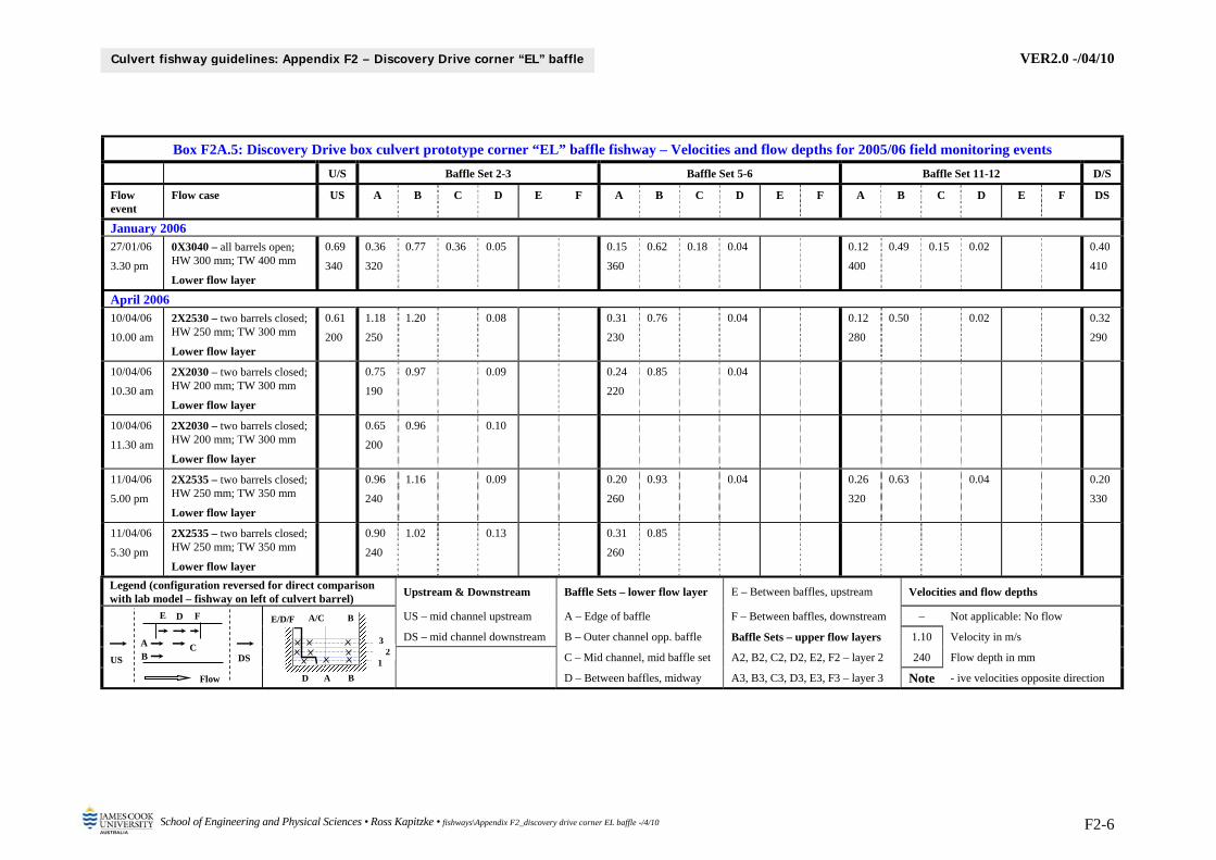
VER2.0 -/04/10
School of Engineering and Physical Sciences • Ross Kapitzke • fishways\Appendix F2_discovery drive corner EL baffle -/4/10 F2-6
Culvert fishway guidelines: Appendix F2 – Discovery Drive corner “EL” baffle
Box F2A.5: Discovery Drive box culvert prototype corner “EL” baffle fishway – Velocities and flow depths for 2005/06 field monitoring events
U/S Baffle Set 2-3 Baffle Set 5-6 Baffle Set 11-12 D/S
Flow event
Flow case US A B C D E F A B C D E F A B C D E F DS
January 2006 27/01/06
3.30 pm
0X3040 – all barrels open; HW 300 mm; TW 400 mm
Lower flow layer
0.69
340
0.36
320
0.77 0.36 0.05 0.15
360
0.62 0.18 0.04 0.12
400
0.49 0.15 0.02 0.40
410
April 2006 10/04/06
10.00 am
2X2530 – two barrels closed; HW 250 mm; TW 300 mm
Lower flow layer
0.61
200
1.18
250
1.20 0.08 0.31
230
0.76 0.04 0.12
280
0.50 0.02 0.32
290
10/04/06
10.30 am
2X2030 – two barrels closed; HW 200 mm; TW 300 mm
Lower flow layer
0.75
190
0.97 0.09 0.24
220
0.85 0.04
10/04/06
11.30 am
2X2030 – two barrels closed; HW 200 mm; TW 300 mm
Lower flow layer
0.65
200
0.96 0.10
11/04/06
5.00 pm
2X2535 – two barrels closed; HW 250 mm; TW 350 mm
Lower flow layer
0.96
240
1.16 0.09 0.20
260
0.93 0.04 0.26
320
0.63 0.04 0.20
330
11/04/06
5.30 pm
2X2535 – two barrels closed; HW 250 mm; TW 350 mm
Lower flow layer
0.90
240
1.02 0.13 0.31
260
0.85
Legend (configuration reversed for direct comparison with lab model – fishway on left of culvert barrel)
Upstream & Downstream Baffle Sets – lower flow layer E – Between baffles, upstream Velocities and flow depths
US – mid channel upstream A – Edge of baffle F – Between baffles, downstream – Not applicable: No flow
DS – mid channel downstream B – Outer channel opp. baffle Baffle Sets – upper flow layers 1.10 Velocity in m/s
C – Mid channel, mid baffle set A2, B2, C2, D2, E2, F2 – layer 2 240 Flow depth in mm
D – Between baffles, midway A3, B3, C3, D3, E3, F3 – layer 3 Note - ive velocities opposite direction
F E
A
D
B C
Flow
US DS
D A B
1 2
3
A/C B E/D/F
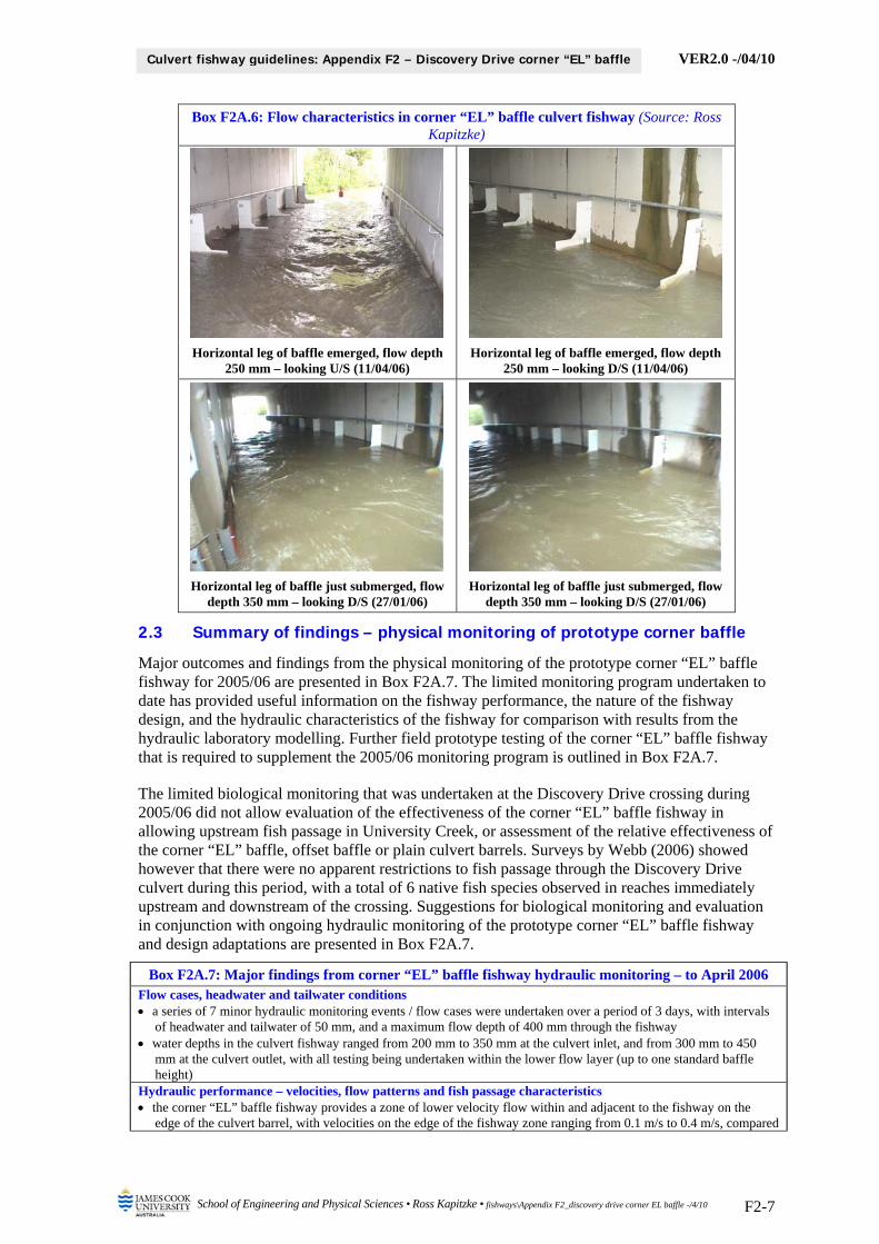
VER2.0 -/04/10
School of Engineering and Physical Sciences • Ross Kapitzke • fishways\Appendix F2_discovery drive corner EL baffle -/4/10 F2-7
Culvert fishway guidelines: Appendix F2 – Discovery Drive corner “EL” baffle
Box F2A.6: Flow characteristics in corner “EL” baffle culvert fishway (Source: Ross Kapitzke)
Horizontal leg of baffle emerged, flow depth 250 mm – looking U/S (11/04/06)
Horizontal leg of baffle emerged, flow depth 250 mm – looking D/S (11/04/06)
Horizontal leg of baffle just submerged, flow depth 350 mm – looking D/S (27/01/06)
Horizontal leg of baffle just submerged, flow depth 350 mm – looking D/S (27/01/06)
2.3 Summary of findings – physical monitoring of prototype corner baffle
Major outcomes and findings from the physical monitoring of the prototype corner “EL” baffle fishway for 2005/06 are presented in Box F2A.7. The limited monitoring program undertaken to date has provided useful information on the fishway performance, the nature of the fishway design, and the hydraulic characteristics of the fishway for comparison with results from the hydraulic laboratory modelling. Further field prototype testing of the corner “EL” baffle fishway that is required to supplement the 2005/06 monitoring program is outlined in Box F2A.7.
The limited biological monitoring that was undertaken at the Discovery Drive crossing during 2005/06 did not allow evaluation of the effectiveness of the corner “EL” baffle fishway in allowing upstream fish passage in University Creek, or assessment of the relative effectiveness of the corner “EL” baffle, offset baffle or plain culvert barrels. Surveys by Webb (2006) showed however that there were no apparent restrictions to fish passage through the Discovery Drive culvert during this period, with a total of 6 native fish species observed in reaches immediately upstream and downstream of the crossing. Suggestions for biological monitoring and evaluation in conjunction with ongoing hydraulic monitoring of the prototype corner “EL” baffle fishway and design adaptations are presented in Box F2A.7.
Box F2A.7: Major findings from corner “EL” baffle fishway hydraulic monitoring – to April 2006 Flow cases, headwater and tailwater conditions a series of 7 minor hydraulic monitoring events / flow cases were undertaken over a period of 3 days, with intervals
of headwater and tailwater of 50 mm, and a maximum flow depth of 400 mm through the fishway water depths in the culvert fishway ranged from 200 mm to 350 mm at the culvert inlet, and from 300 mm to 450
mm at the culvert outlet, with all testing being undertaken within the lower flow layer (up to one standard baffle height)
Hydraulic performance – velocities, flow patterns and fish passage characteristics the corner “EL” baffle fishway provides a zone of lower velocity flow within and adjacent to the fishway on the
edge of the culvert barrel, with velocities on the edge of the fishway zone ranging from 0.1 m/s to 0.4 m/s, compared
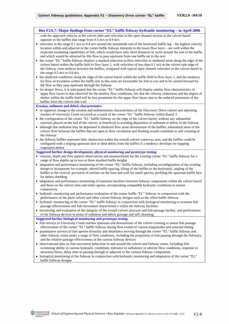
VER2.0 -/04/10
School of Engineering and Physical Sciences • Ross Kapitzke • fishways\Appendix F2_discovery drive corner EL baffle -/4/10 F2-8
Culvert fishway guidelines: Appendix F2 – Discovery Drive corner “EL” baffle
Box F2A.7: Major findings from corner “EL” baffle fishway hydraulic monitoring – to April 2006 with the approach velocity at the culvert inlet and velocities in the open channel section in the culvert barrel opposite to the baffles that range from 0.5 m/s to 0.9 m/s
velocities in the range 0.1 m/s to 0.4 m/s around the streamside end of the horizontal baffle leg – the highest velocity location within and adjacent to the corner baffle fishway elements in the lower flow layer – are well within the expected swimming capabilities of fish, which would have only short distances to swim around the end of the baffle, and which would be attracted by this flow to pass upstream from one baffle set to the next
the corner “EL” baffle fishway displays a marked reduction in flow velocities in sheltered areas along the edge of the culvert barrel within the baffle field in flow layer 1, with velocities of less than 0.1 m/s at the culvert side edge of the fishway zone midway between the baffles, compared with typical open channel velocities in the culvert barrel in the range 0.5 m/s to 0.8 m/s
the sheltered conditions along the edge of the culvert barrel within the baffle field in flow layer 1, and the tendency for flow recirculation within the baffle sets in this zone are favourable for fish to rest and to be carried forward by the flow as they pass upstream through the fishway
for deeper flows, it is anticipated that the corner “EL” baffle fishway will display similar flow characteristics in upper flow layers to that observed for the shallow flow conditions, but that the velocity reductions and the degree of shelter within the baffle field will be less prominent for the upper flow layers due to the reduced protrusion of the baffles from the culvert side wall
Erosion, sediment and debris characteristics no apparent change to the erosion and sedimentation characteristics of the Discovery Drive culvert and adjoining
reaches of University Creek occurred as a result of the corner “EL” baffle fishway within Barrel 3 the configuration of the corner “EL” baffle fishway on the edge of the culvert barrel, without any substantial
structure placed on the bed of the culvert, is beneficial in avoiding deposition of sediment or debris in the fishway although fine sediment may be deposited in sheltered flow areas downstream of the baffles, substantial areas of the
culvert floor between the baffles that are open to flow circulation and flushing would contribute to self cleaning of the fishway
the fishway baffles represent little obstruction within the overall culvert waterway area, and the baffles could be configured with a sloping upstream face to shed debris from the baffles if a tendency develops for trapping vegetation debris
Suggested further design development, physical monitoring and prototype testing velocity, depth and flow pattern observations and measurements for the existing corner “EL” baffle fishway for a
range of flow depths up to two or three standard baffle heights adaptation and performance monitoring of the corner “EL” baffle fishway, including reconfiguration of the existing
design to incorporate for example: altered baffle spacing, tilting of the baffles to the horizontal, angling of the baffles to the vertical, provision of notches on the base and wall for small species, profiling the upstream baffle face for debris shedding
adaptation and performance monitoring of transition facilities between fishway components within the culvert barrel and those on the culvert inlet and outlet aprons, incorporating compatible hydraulic conditions to ensure connectivity
hydraulic monitoring and performance evaluation of the corner baffle “EL” fishway in comparison with the performance of the plain culvert and other culvert fishway designs such as the offset baffle fishway
hydraulic monitoring of the corner “EL” baffle fishway in conjunction with biological monitoring to examine fish passage effectiveness and fish movement characteristics within the fishway facilities
monitoring and evaluation of the integrity of the overall culvert structure and fish passage facility, and performance of the fishway devices in terms of sediment and debris passage and self cleansing
Suggested further biological monitoring and prototype testing fish surveys in University Creek reaches upstream and downstream of the culvert crossing to assess fish passage
effectiveness of the corner “EL” baffle fishway during flow events of various magnitudes and seasonal timing quantitative surveys of fish species diversity and abundance moving through the corner “EL” baffle fishway and
other fishway zones under a range of flow conditions, including the proportion of fish passing through the fishways, and the relative passage effectiveness of the various fishway devices
observational data on fish movement behaviour in and around the culvert and fishway zones, including fish swimming ability in various hydraulic conditions, tolerance to turbulence or adverse flow conditions, response to attraction flows, delay time in passing through or adjacent to the various fishway components
biological monitoring of the fishway in conjunction with hydraulic monitoring and adaptation of the corner “EL” baffle fishway designs

VER2.0 -/04/10
School of Engineering and Physical Sciences • Ross Kapitzke • fishways\Appendix F2_discovery drive corner EL baffle -/4/10 F2-9
Culvert fishway guidelines: Appendix F2 – Discovery Drive corner “EL” baffle
3 HYDRAULIC LABORATORY MODELLING
Hydraulic laboratory modelling has been used to assess the hydraulic performance characteristics of the corner “EL” baffle fishway for box culverts, to compare the performance characteristics of the fishway model with that of the Discovery Drive prototype fishway, and to consider design adaptations that may be suitable for various culvert fishway installations.
This section describes hydraulic laboratory modelling for the corner “EL” baffle fishway for box culverts undertaken at the hydraulic model facility at JCU School of Engineering. The major outcomes and findings for the work until 2006 are summarised, including flow patterns and velocities for a range of flow depths (Ferrando 2006). More recent modelling has examined variations of hydraulic characteristics with culvert slope and baffle spacing (Powell 2007).
The hydraulic laboratory modelling equipment and methods used for the corner “EL” baffle are the same as those used for the offset baffle fishway for box culverts (see Appendix F1). This includes a 1:5 scale model of the culvert fishway device fitted within a model of the Discovery Drive box culvert. Velocity profiles for various water depths and discharges are measured with a Swoffer 3000 miniature propeller current meter, and visual, photo and video observation are made with the assistance of die tracers and other visualisation techniques to study flow patterns and turbulence. Velocity and flow depth measurements are obtained from baffle sets in the mid section of the fishway model where uniform flow is fully established.
3.1 Results from hydraulic laboratory modelling
Data on flow patterns, velocity, depth and discharge characteristics for the corner “EL” baffle fishway model with the standard baffle spacing have been obtained for a culvert slope of 1.0 % (Ferrando 2006). The testing involved a series of flow cases at flow depths of one, two and three standard baffle heights, with flow patterns and velocities recorded within each of the flow layers for the range of flow depths / discharges. Flow pattern, velocity, depth and discharge observations and measurements were compiled and evaluated as follows:
surface and subsurface flow patterns through culvert and fishway baffles sets, showing flow continuity and streamlines, recirculation, zones of high or low velocity and/or turbulence
velocity variation with flow depth / discharge at critical points within baffle sets in the lower flow layer (one standard baffle height)
velocity variation with flow layers (one, two and three standard baffle heights) at critical points within baffle sets for the maximum flow case (three baffle heights flow depth)
variations in dimensionless discharge and dimensionless velocity at key points in the culvert with dimensionless flow depth
comparison between hydraulic characteristics of various fishway designs, the plain culvert, and prototype fishway facilities (tested in the field to a maximum flow depth of 400 mm)
The effects of the corner “EL” baffle fishway on velocities within the fishway, and on flow circulation and shelter / flow retardance within the various flow layers, can be seen from the tabulation of velocities and flow depths (Box F2A.8), and from photographs and interpretations of flow patterns within the culvert fishway (Boxes F2A.9 and F2A.10). The velocity and flow depth data (Box F2A.8) encompasses the lower flow layer 1 for the range of flow depths / discharges, and flow layers 1, 2 and 3 for the maximum flow depth / discharge case. The flow pattern interpretations of surface and subsurface flow lines (Box F2A.10) relate to the lower flow layer when the baffle leg is emerged, and the lower and upper flow layers when the baffle leg is submerged to two or more standard baffle height flow depths. Comparisons can be made with data for the plain culvert and for the prototype fishway (Boxes F2A.5 and F2A.6), which are available for flow depths to slightly greater than one standard baffle height.

VER2.0 -/04/10
School of Engineering and Physical Sciences • Ross Kapitzke • fishways\Appendix F2_discovery drive corner EL baffle -/4/10 F2-10
Culvert fishway guidelines: Appendix F2 – Discovery Drive corner “EL” baffle
Box F2A.8: Box culvert corner “EL” baffle fishway hydraulic laboratory model – Velocities and flow depths for baffle set 3-4 (After: Ferrando 2006)
Discharge 3: Flow depth = 3 baffle heights Discharge 2: Flow depth = 2 baffle heights Discharge 1: Flow depth = 1 baffle height
Flow case A B C D E F A B C D E F A B C D E F
Variation with discharge – velocities in lower flow layer
Discharge Q3 – flow depth 900 1.40 1.70 ? 0.25 0.30 0.19
Discharge Q2 – flow depth 600 1.23 1.42 1.05 0.20 0.01 0.15
Discharge Q1 – flow depth 300 1.14 1.22 0.96 0.20 0.02 0.22
Variation with flow layers – velocities in flow layers for maximum flow case (Discharge 3)
Flow layer 3 – top 300 1.07 1.84 1.45 0.77 0.74 0.45
Flow layer 2 – middle 300 1.32 1.87 1.69 0.45 0.59 0.54
Flow layer 1 – lower 300 1.40 1.70 ? 0.25 0.30 0.19
Legend Notes Baffle Sets – lower flow layer E – Between baffles, upstream Velocities and flow depths
Velocity and flow depth in equivalent prototype data
A – Edge of baffle F – Between baffles, downstream – Not applicable: No flow
B – Outer channel opp. baffle Baffle Sets – upper flow layers 1.10 Velocity in m/s
Measurements within baffle set 3-4
C – Mid channel, mid baffle set A2, B2, C2, D2, E2, F2 – layer 2 - 0.3 - ive velocities opposite direction
D – Between baffles, midway A3, B3, C3, D3, E3, F3 – layer 3
F E
A
D
B C
Flow
US DS
D A B
1 2
3
A/C B E/D/F
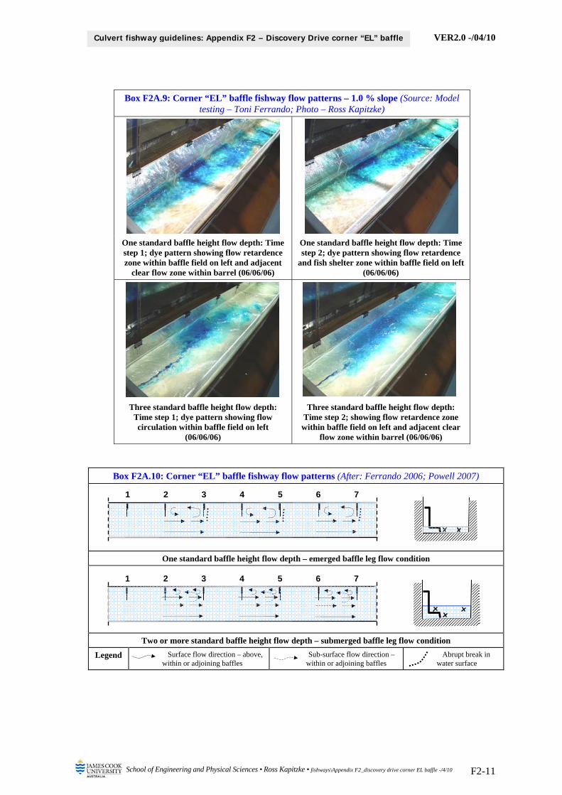
VER2.0 -/04/10
School of Engineering and Physical Sciences • Ross Kapitzke • fishways\Appendix F2_discovery drive corner EL baffle -/4/10 F2-11
Culvert fishway guidelines: Appendix F2 – Discovery Drive corner “EL” baffle
Box F2A.9: Corner “EL” baffle fishway flow patterns – 1.0 % slope (Source: Model testing – Toni Ferrando; Photo – Ross Kapitzke)
One standard baffle height flow depth: Time step 1; dye pattern showing flow retardence zone within baffle field on left and adjacent
clear flow zone within barrel (06/06/06)
One standard baffle height flow depth: Time step 2; dye pattern showing flow retardence
and fish shelter zone within baffle field on left (06/06/06)
Three standard baffle height flow depth: Time step 1; dye pattern showing flow circulation within baffle field on left
(06/06/06)
Three standard baffle height flow depth: Time step 2; showing flow retardence zone within baffle field on left and adjacent clear
flow zone within barrel (06/06/06)
Box F2A.10: Corner “EL” baffle fishway flow patterns (After: Ferrando 2006; Powell 2007)
One standard baffle height flow depth – emerged baffle leg flow condition
Two or more standard baffle height flow depth – submerged baffle leg flow condition
Legend Surface flow direction – above, within or adjoining baffles
Sub-surface flow direction – within or adjoining baffles
Abrupt break in water surface
2 3 4 5 6 71
2 3 4 5 6 71

VER2.0 -/04/10
School of Engineering and Physical Sciences • Ross Kapitzke • fishways\Appendix F2_discovery drive corner EL baffle -/4/10 F2-12
Culvert fishway guidelines: Appendix F2 – Discovery Drive corner “EL” baffle
3.2 Summary of findings – corner “EL” baffle hydraulic laboratory modelling
Major outcomes and findings from the hydraulic laboratory modelling of the corner “EL” baffle fishway with standard baffle spacing and at 1.0 % slope are presented in Box F2A.11. This includes data for flow depths through the fishway of up to 3 standard baffle heights, and comparisons where appropriate with results from the Discovery Drive prototype corner “EL” baffle fishway (see Section 2.3 of this appendix F2).
Box F2A.11: Major outcomes and findings from hydraulic laboratory modeling of corner “EL” baffle fishway for box culverts (model results after Ferrando 2006; prototype data from field testing – see
Section 2.3) Flow cases, fishway designs, flow depths and formulae
testing for the corner “EL” baffle fishway and the plain culvert barrel included flows Q1 (one baffle height), Q2 (two baffle heights), Q3 (three baffle heights) for culvert slope of 1.0%
all velocities expressed in equivalent prototype values, which are converted using the following: 1
5mp vv where
vp = velocity in prototype fishway; vm = velocity in model fishway
Flow characteristics of corner “EL” baffle fishway – emerged baffle condition (flow depth < 300 mm)
for emerged flow conditions, with flow depth at or below one standard baffle height, flow through the corner “EL” baffle fishway retains streamlined flow on the open side of the culvert outside the baffle field, but causes flow obstruction / shelter on the baffle side of the culvert and some horizontal flow circulation within the baffle sets
flow recirculation in a horizontal plane in the lower flow layer within the baffle sets on the left moves in a counter-clockwise direction toward the culvert wall, and is established in a single large eddy between the baffles
Flow characteristics of corner “EL” baffle fishway – submerged baffle condition (flow depth > 300 mm) for submerged flow conditions, with flow depth greater than one standard baffle height, flow through the corner
“EL” baffle fishway retains streamlined flow on the open side of the culvert outside the baffle field, but causes flow obstruction / shelter on the baffle side of the culvert and some horizontal flow circulation within the baffle sets in the lower flow layer and in the upper flow layers
flow recirculation in a horizontal plane in the upper flow layers within the baffle sets on the left moves in a counter-clockwise direction toward the culvert wall, and is established in several eddies between the baffles that are smaller than the single eddy that is retained in the lower flow layer
compared with conditions in the sheltered areas within the baffle sets along the baffle side of the culvert in lower flow layer 1, the degree of shelter and recirculation within the baffle field and the size of the eddies is reduced in the upper flow layers due to the reduced protrusion of the baffles from the culvert side wall
velocities at the streamside end of the horizontal baffle leg in the lower flow layer are in the range 1.1 m/s to 1.4 m/s for discharges ranging from one baffle height flow depth to three baffle heights flow depth, compared with velocities at corresponding locations in the prototype of up to 0.4 m/s for the low flow discharge2
velocities in sheltered areas along the edge of the culvert barrel within the baffle field in flow layer 1 are up to 0.3 m/s for discharges ranging from one baffle height flow depth to three baffle heights flow depth, compared with velocities at corresponding locations in the prototype of up to 0.1 m/s for the low flow discharge2
velocities in the open channel section in the culvert barrel opposite the baffles in flow layer 1 range from 1.2 m/s to 1.7 m/s for discharges ranging from one baffle height flow depth to three baffle heights flow depth, compared with velocities at corresponding locations in the prototype ranging from 0.5 m/s to 0.9 m/s for the low flow discharge2
velocities in the open channel section in the culvert barrel opposite the baffles in flow layer 1 increase with discharge and flow depth in the culvert, whereas velocities in sheltered areas along the edge of the culvert barrel within the baffle field in flow layer 1 show only small increases with increased discharge and flow depth, indicating the corner “EL” baffle fishway provides conditions conducive to fish passage for a range of flow depths in the culvert
for a discharge corresponding to three baffle heights flow depth, velocities at the streamside end of the horizontal baffle leg in the lower flow layer and at the streamside end of the vertical baffle leg in the upper flow layers are in the range 1.1 m/s to 1.4 m/s, compared with velocities in the open channel section in the culvert barrel opposite the baffles that range from 1.7 m/s to 1.9 m/s through these flow layers for this flow depth / discharge
for a discharge corresponding to three baffle heights flow depth, velocities in sheltered areas along the edge of the culvert barrel within the baffle field in lower flow layer 1 are in the range 0.2 m/s to 0.3 m/s, compared with velocities in sheltered areas along the edge of the culvert barrel within the baffle field in upper flow layers, which are in the range 0.5 m/s to 0.7 m/s, apparently due to the reduced protrusion of the baffles from the culvert side wall
Comparative hydraulic performance of corner “EL” baffle and offset baffle fishways and plain culvert velocities in sheltered areas within the baffle field in the lower flow layer of the corner “EL” baffle fishway do not
increase significantly as the discharge and flow depth increases, whereas velocities at all locations within the lower flow layer for the offset baffle fishway tend to increase as the flow in the culvert and the depth of submergence of
2 prototype may be affected by flow sheltering in stream channel and raised tailwater conditions

VER2.0 -/04/10
School of Engineering and Physical Sciences • Ross Kapitzke • fishways\Appendix F2_discovery drive corner EL baffle -/4/10 F2-13
Culvert fishway guidelines: Appendix F2 – Discovery Drive corner “EL” baffle
Box F2A.11: Major outcomes and findings from hydraulic laboratory modeling of corner “EL” baffle fishway for box culverts (model results after Ferrando 2006; prototype data from field testing – see
Section 2.3) the fishway increases
whereas for the offset baffle fishway with submerged flow conditions, velocities in open channel sections in upper flow layers above the offset baffle structure are much greater than velocities in lower flow layers within the baffle structure, velocities in sheltered areas along the edge of the culvert barrel within the baffle field in upper flow layers of the corner “EL” baffle fishway are substantially less than open channel velocities outside the baffle field, indicating the corner baffle fishway provides conditions conducive to fish passage for a range of flow depths
although the findings are not conclusive, the corner “EL” baffle fishway causes less reduction in flow conveyance than the offset baffle fishway for discharges of up to three baffle heights flow depth in the culvert, particularly for shallow flow depths where the bed of the culvert is unobstructed in the corner baffle design
the open channel section of the corner “EL” baffle fishway provides less resistance to flow than the offset baffle fishway and allows comparatively more flow through the culvert, which will provide a greater attraction flow for fish in the corner “EL” baffle fishway design than the offset baffle fishway

VER2.0 -/04/10
School of Engineering and Physical Sciences • Ross Kapitzke • fishways\Appendix F2_discovery drive corner EL baffle -/4/10 F2-14
Culvert fishway guidelines: Appendix F2 – Discovery Drive corner “EL” baffle
4 BIBLIOGRAPHY Ferrando, T. 2006, Performance characteristics of offset baffle and corner baffle fishways for box culverts,
Bachelor of Engineering Thesis, James Cook University School of Engineering. Kapitzke, I.R. 2006a, Bruce Highway Corduroy Creek to Tully planning study Provisions for fish passage
– Road corridor scale Assessment Task 1A, report to Maunsell Australia and Department of Main Roads. Kapitzke, I.R. 2006b, Discovery Drive offset baffle fishway for box culverts (Prototype Fishway # 1): Case
study project design and prototype monitoring report to April 2005, report to Dept of Main Roads. Kapitzke, I.R. 2006c, Douglas Arterial Project rock ramp fishway for open channels (Prototype Fishway #
2): Case study project design and prototype monitoring report to April 2005, report to Dept Main Roads. Kapitzke, I.R. 2007a, Bruce Highway Corduroy Creek to Tully High School Provisions for Fish Passage –
Preliminary Design Assessment Tasks 1B and 2, report to Maunsell Australia and Dept of Main Roads. Kapitzke, I.R. 2007b, Discovery Drive corner baffle fishway for box culverts (Prototype Fishway # 4):
Case study project design and prototype monitoring report to April 2006, report to Dept of Main Roads. Kapitzke, I.R. 2007c, Solander Road pipe culvert fishway (Prototype Fishway # 3): Case study project
design and prototype monitoring report to April 2006, report to Department of Main Roads. Powell, C. 2007, Design adaptations for offset baffle and corner baffle fishways for box culverts, Bachelor
of Engineering Thesis, James Cook University School of Engineering. Webb, A.C. 2006, Fishway biomonitoring January – April 2006, report prepared by James Cook
University School of Tropical Biology.
Ross Kapitzke James Cook University School of Engineering and Physical Sciences April 2010 – VER2.0