Fish Passage Planning and Design - James Cook … Fishway Planning and Design Guidelines Part C –...
57
Culvert Fishway Planning and Design Guidelines Part C – Fish Migration Barriers and Fish Passage Options for Road Crossings Ross Kapitzke James Cook University School of Engineering and Physical Sciences April 2010 – VER2.0 Fish Passage Planning and Design
Transcript of Fish Passage Planning and Design - James Cook … Fishway Planning and Design Guidelines Part C –...

Culvert Fishway Planning and Design GuidelinesPart C – Fish Migration Barriers and Fish Passage Options for Road Crossings
Ross Kapitzke James Cook University School of Engineering and Physical Sciences
April 2010 – VER2.0
Fish Passage Planning and Design

VER2.0 -/04/10
School of Engineering and Physical Sciences • Ross Kapitzke • fishways\C_fish passage barriers and options -/4/10 C-i
Culvert fishway guidelines: Part C – Fish passage barriers and options
James Cook University School of Engineering and Physical Sciences Culvert Fishway Planning and Design Guidelines Part C – Fish Migration Barriers and Fish Passage Options for Road Crossings Contents
1 INTRODUCTION 1
2 FISH MIGRATION BARRIERS AT ROAD-WATERWAY CROSSINGS 2 2.1 Hydraulic barriers to fish migration at road-waterway crossings 2 2.2 Velocity barriers to fish passage in culverts 4 2.3 Other barriers to fish migration at structures 10
3 FISH PASSAGE DESIGN APPROACHES AND FISHWAY CONCEPTS 12 3.1 Context for culvert fishway design in Australia 12 3.2 Fish passage design strategies for road-waterway crossings 13 3.3 Hydraulic design approach for culvert fishways 16 3.4 Shortcomings of other fish passage design approaches 17
4 FISHWAY CONFIGURATION OPTIONS FOR ROAD CROSSINGS 19 4.1 Design requirements for fish passage 19 4.2 Overall fishway configuration at crossing 20 4.3 Fish passage facilities – Bruce Highway Corduroy Creek to Tully project 26 4.4 Fish passage facilities – University Creek Solander Road pipe culvert 28
5 APPLICATION AND CHARACTERISTICS OF FISHWAY COMPONENTS 33
6 FISH PASSAGE PROVISIONS AT TEMPORARY ROAD CROSSINGS 38 6.1 Fish migration barriers at temporary road-waterway crossings 38 6.2 Fish passage design assessment for temporary crossings 41 6.3 Mitigation measures for fish passage at temporary crossings 44 6.4 Temporary road crossing – University Creek Douglas Arterial project 47 6.5 Temporary road crossing – Bruce Highway Corduroy Creek project 50
7 BIBLIOGRAPHY 55

VER2.0 -/04/10
School of Engineering and Physical Sciences • Ross Kapitzke • fishways\C_fish passage barriers and options -/4/10 C-1
Culvert fishway guidelines: Part C – Fish passage barriers and options
James Cook University School of Engineering and Physical Sciences Culvert Fishway Planning and Design Guidelines Part C – Fish Migration Barriers and Fish Passage Options for Road Crossings
1 INTRODUCTION
In addressing the need for fish passage at road crossings and other waterway structures, in determining fish passage provisions that should be made at the structure, and in developing facilities to overcome the fish migration barriers at the site, road designers, waterway managers, environmental officers and scientists require an understanding of the features of waterway structures that represent barriers to fish movement, knowledge of the fish passage options available, and information on configuration and performance characteristics of the various fishway components for use at the structures.
These Guidelines Part C examine the various fish passage options for use, and aim to:
identify fish migration barriers at road-waterway crossings and describe these barriers in terms of adverse conditions within the various hydraulic zones of the crossing
outline fish passage design approaches and fishway concepts, with the focus on the hydraulic design approach for culvert fishways using baffles
identify fishway configuration options and the characteristics of fishway components for use within various hydraulic zones at a structure, and illustrate these provisions for the Bruce Highway Corduroy Creek to Tully and University Creek Solander Road case study projects
identify fish migration barrier problems and potential mitigation options to provide for fish passage at temporary road crossings, and illustrate these provisions for the University Creek Douglas Arterial Road and Bruce Highway Corduroy Creek to Tully case study projects
The information from Guidelines Part C is used in other parts of these Guidelines to:
evaluate fish migration barriers within the various hydraulic zones of the waterway structure, and identify fishway components and configuration options to meet the particular design requirements for the structure (Guidelines Part E – Fish Passage Design: Site Scale)
guide the design configurations for road-waterway crossings incorporating fish passage provisions at temporary crossings (Guidelines Part E – Fish Passage Design: Site Scale)
These Guidelines deal with the Concept and Preliminary Design phases of planning and design procedures for road and other infrastructure projects. They relate to fish passage facilities at road crossings such as culverts and open channel sections, and although they do not deal specifically with other waterway structures such as weirs, flood gates, tide gates, or control structures, are also relevant in many ways to these structures. Examples of various fish passage measures that can be adopted to deal with a range of fish migration barriers at road crossings can be seen in the Solander Road prototype fishways on University Creek in Townsville (Box C1.1).
Box C1.1: Fish passage devices adopted for a range of fish migration barrier types at Solander Road crossing of University Creek in Townsville (Source: Ross Kapitzke)
Rock ramp / cascade fishway to overcome water surface drop at culvert apron
downstream of culvert (09/04/06)
Apron baffle fishway on culvert apron, and corner “Quad” baffle and offset baffle
fishways in pipe barrels (09/04/06)

VER2.0 -/04/10
School of Engineering and Physical Sciences • Ross Kapitzke • fishways\C_fish passage barriers and options -/4/10 C-2
Culvert fishway guidelines: Part C – Fish passage barriers and options
2 FISH MIGRATION BARRIERS AT ROAD-WATERWAY CROSSINGS
Fish migration barriers at road crossings and other waterway structures commonly occur as a result of adverse hydraulic conditions at box culverts, pipe culverts and causeways, but may also occur at bridge crossings and other constructed waterways, where channelisation, grade control or other structures sometimes produce adverse conditions for upstream fish movement. In addition to hydraulic barriers at road-waterway crossings and open channel sections that are the focus of these Guidelines, other barriers to fish movement in the catchment may be associated with the following physical or behavioural barriers, which are not specifically addressed here:
hydraulic and physical barriers at dams, weirs, flood gates, tide gates, or control structures barriers associated with pipelines, footings, or other infrastructure in the waterway physical barriers due to sediment or debris blockages at waterway structures altered streamflow regimes in waterways changing cues to migration modified stream and aquatic habitat due to ponding, channelisation or vegetation removal poor water quality or other environmental degradation in the stream such as weed blockage natural barriers such as waterfalls or rapids
The following sections describe the principal types of hydraulic barriers to upstream fish passage at conventional road-waterway crossings and open channel sections, and outline methods for evaluating velocity barrier effects in culverts in terms of waterway conditions and fish swimming capabilities. Some discussion of other barriers related to lack of attraction flow, debris or sediment blockage, downstream passage, structure drown-out, and light barriers is also provided. Fish passage design approaches and fishway concepts for road-waterway crossings are discussed in Chapter 3. Fishway configuration options are outlined in Chapter 4, and the application and performance characteristics of various fishway components are presented in Chapter 5. The method for evaluating fish migration barriers and for design of fish passage facilities at a waterway structure are outlined in Guidelines Part E – Fish Passage Design: Site Scale.
2.1 Hydraulic barriers to fish migration at road-waterway crossings
Road-waterway crossings may represent fish migration barriers if hydraulic conditions at the structures are more severe than swim capabilities or do not suit behavioural characteristics of fish attempting to pass upstream. This will usually occur as a result of major changes to natural waterway conditions at the site, leading to the following principal types of hydraulic barriers:
high velocity reduced flow depth lack of resting place or shelter excess turbulence water surface drop
These limiting hydraulic conditions may lead to total, partial or temporal barriers at waterway structures, affecting part or all of the fish community for part or all of the stream flow range. These barrier effects are classified by Dane (1978) as follows:
Degree of barrier Description Effect of barrier
total barrier impassable to all fish at all flows - all of the time
exclusion of fish entirely or from portions of a waterway
isolation of fish populations upstream of a barrier
partial barrier impassable to some fish at all flows - all of the time
exclusion of certain fish species, life stages, or maturity entirely or from portions of a waterway
isolation of certain fish species, life stages, or maturity upstream of a barrier
temporal barrier impassable to all fish at some flows - some of the time
delay of movement beyond the barrier for some period of time

VER2.0 -/04/10
School of Engineering and Physical Sciences • Ross Kapitzke • fishways\C_fish passage barriers and options -/4/10 C-3
Culvert fishway guidelines: Part C – Fish passage barriers and options
Fish migration barriers due to adverse hydraulic conditions in road crossings (e.g. box culverts, pipe culverts, causeways) may occur within any of the various drainage structure components such as the inlet and outlet structures, the culvert barrel, and the overtopping section of the roadway. The upstream and downstream sections of the stream channel adjoining the crossing may also represent fish migration barriers if the waterway structure and associated channel are configured to produce adverse conditions such as high velocities, turbulence, or water surface drops. Consideration of fish migration barriers at the crossing should be given, not only to hydraulic conditions within the culvert barrels, but to conditions throughout the structure and adjoining waterway, to enable fish passage through all hydraulic zones from downstream to upstream at the structure (see Guidelines Part E – Fish Passage Design: Site Scale).
Hydraulic conditions affecting fish passage through the waterway structure must be considered over a range of stream flows to encompass the design flow range for fish passage (see Guidelines Part B – Fish Migration and Fish Species Movement Behaviour). This includes the low flow condition (flow up to approx 0.5 m deep – inundating channel bed for defined waterway), and medium flow condition (flow from approx 0.5 m to approx 1.5 m deep – below low flow channel bench for defined waterway). Whereas velocities in culvert barrels will usually be greater at the medium flow condition than at low flow, barriers such as water surface drops at culvert outlets and shallow flow depths on outlet aprons may occur at low flows rather than at the higher flows.
The hydraulic barriers to fish migration that commonly occur in various hydraulic zones within typical road-waterway crossing structures are illustrated and described below (Boxes C2.1 and C2.2). Principal hydraulic barrier types and their common occurrence within box culvert, pipe culvert and causeway structures are shown in Box C2.1, along with typical configuration, flow profiles and hydraulic zones for these crossings. Box C2.2 identifies typical locations and configurations of these hydraulic barriers to fish migration and describes them in terms of hydraulic characteristics and effects on fish movement within these zones.
Box C2.1: Common occurrence of principal hydraulic barriers to fish migration within culvert zones at road-waterway crossings (Source: Ross Kapitzke)
Hydraulic barrier type
Zone D: Culvert inlet and upstream
channel
Zone C: Culvert barrel
Zone B: Culvert outlet and
downstream apron
Zone A: Downstream
channel
High velocity Shallow water depth
Lack of resting place
Excess turbulence Water surface drop
Example culvert configuration, flow profiles and hydraulic zones: Box culvert
Culvert inlet and upstream channel
Culvert barrel
Downstream channel
Culvert outlet and downstream apron
Zone D Zone C Zone B Zone A
Multi–cell box culvert
Flow Low flow
Medium flow

VER2.0 -/04/10
School of Engineering and Physical Sciences • Ross Kapitzke • fishways\C_fish passage barriers and options -/4/10 C-4
Culvert fishway guidelines: Part C – Fish passage barriers and options
Box C2.1: Common occurrence of principal hydraulic barriers to fish migration within culvert zones at road-waterway crossings (Source: Ross Kapitzke)
Example culvert configuration, flow profiles and hydraulic zones: Pipe culvert and causeway
2.2 Velocity barriers to fish passage in culverts
One of the dominant and often most significant barriers to upstream fish passage at a road-waterway crossing is due to high velocities that commonly occur within the culvert barrel, at the culvert inlet and culvert outlet, and on the downstream culvert apron. The ability of fish to overcome these velocity barriers at the structure depends on the culvert flow velocity conditions and the fish swimming capability, which varies with the species and the life stage (e.g. juvenile or adult). The degree to which culvert flow conditions represent a velocity barrier to fish movement, and the need to adopt fishway devices to modify velocity conditions to allow fish passage through the culvert can be assessed by examining fish swim capabilities, flow velocities, and the length of the culvert barrel and distances between rest points for fish in the structure.
Flow conditions within the culvert barrel or other hydraulic zones of the waterway structure can be examined to determine if fish of various swimming capabilities are able to negotiate their way upstream for the prevailing flow velocity under a range of design flow conditions for the structure (see Guidelines Part B – Fish Migration and Fish Species Movement Behaviour). Fish will use either a burst swim mode, where they swim at maximum speed for short periods of up to 20 seconds, or a prolonged swim mode where they swim without rest for a period of up to 200 minutes. The distance fish can travel upstream under these alternative swim modes depends on the culvert flow velocity and their swim capability, and can be expressed in a rudimentary manner as follows:
X = (U - V) tm
where X = distance travelled (m) U = maximum swimming speed of fish V = water velocity (m/s) tm = endurance time (secs)
Culvert inlet and upstream channel
Culvert barrel Downstream channel and apron drop-off
Culvert outlet and downstream apron
Zone D Zone C Zone B Zone A
Multi–barrel pipe culvert, causeway and apron
Flow
Low flow Medium flow

VER2.0 -/04/10
School of Engineering and Physical Sciences • Ross Kapitzke • fishways\C_fish passage barriers and options -/4/10 C-5
Culvert fishway guidelines: Part C – Fish passage barriers and options
Box C2.2: Type and characteristics of principal hydraulic barriers to fish passage at road-waterway crossings (Photo source: Ross Kapitzke)
Typical location and configuration of hydraulic barrier Hydraulic characteristics and effects on fish movement
High velocity (Photo -/03/97: Box culvert barrel and culvert outlet)
high velocities may occur within the culvert barrel, at the culvert inlet and culvert outlet and on the downstream apron
high velocities may result from steep gradient waterways and culverts, uniform channel and lack of hydraulic roughness in culvert, constriction of waterway area at the culvert, upstream head build-up, low tailwater levels
high velocities at the culvert outlet and on the downstream apron may lead to downstream bed and bank erosion, and a water surface drop, which may form another fish migration barrier at the crossing
the average velocity through the culvert is typically higher than in a natural stream channel section with identical waterway area due to the streamlining and reduced roughness in the culvert
culvert velocities will form a barrier to upstream fish movement if the length to travel between rest points is greater than the distance traveled by fish under prolonged or burst and rest swim modes
reduced velocities in the hydraulic boundary layer on the edge of the culvert barrels are seldom adequate for upstream fish passage through the length of the culvert
acceleration and constriction of flow at the upstream end of the culvert barrel and at the culvert inlet increase velocity locally, causing a barrier to upstream movement and a tendency to sweep fish downstream after passing through the culvert barrel
Shallow water depth (Photo -/02/02: Pipe culvert downstream apron)
shallow water depths may occur within the culvert barrel, at the culvert inlet, culvert outlet and on the downstream apron
shallow water depths may result from steep gradient waterways and culverts, low tailwater levels, wide culvert bases that disperse flow
box culverts tend to disperse flow and have shallower water depths than pipe culverts, and downstream culvert aprons also tend to reduce water depth through flow dispersion
shallow water represents a barrier to fish movement when the depth is insufficient to allow fish to swim effectively, particularly larger fish species
fish may become injured if they attempt to move through water that is too shallow, particularly in high energy flow conditions
the desired minimum flow depth for small and medium size species is reportedly 0.2 – 0.3m

VER2.0 -/04/10
School of Engineering and Physical Sciences • Ross Kapitzke • fishways\C_fish passage barriers and options -/4/10 C-6
Culvert fishway guidelines: Part C – Fish passage barriers and options
Box C2.2: Type and characteristics of principal hydraulic barriers to fish passage at road-waterway crossings (Photo source: Ross Kapitzke)
Typical location and configuration of hydraulic barrier Hydraulic characteristics and effects on fish movement
Lack of resting place or shelter (Photo -/01/04: Box culvert barrel)
lack of resting place or shelter for fish may occur within the culvert barrel, at the culvert inlet and outlet, on the downstream apron, and sometimes within adjoining open channel sections
lack of resting place or low velocity zones for fish may result from regular channel or culvert cross section, simplified channel form and lack of substrate complexity
lack of resting place or shelter is more severe in an artificial channel or culvert than in a natural stream, which commonly has diverse channel form and complex substrate (e.g. logs, rocks)
lack of resting place or shelter will form a barrier to upstream fish movement if the length between shelter areas is greater than the distance traveled by fish under prolonged or burst and rest swim modes
low velocity zones in the hydraulic boundary layer on the edge of the culvert barrels seldom represent an adequate resting zone for fish due to flow and velocity fluctuations and the lack of structure protection
isolated or minimal shelter areas such as the hydraulic boundary layer on the edge of the culvert barrels are commonly smaller than the fish size (particularly adults), and present difficulty for groups of fish to traverse these narrow and unstable paths
lack of resting place or shelter at the culvert inlet may tend to sweep fish downstream after passing through the culvert barrel
a lack of resting place or shelter where fish can rest and recover in their upstream movement through a culvert may lead to exhaustion and injury as the fish are swept downstream
Excess turbulence (Photo -/02/02: Outlet from pipe barrel)
excess turbulence may occur within the culvert barrel, at the culvert inlet and outlet, on the downstream apron, and within the downstream channel
excess turbulence may result from steep gradient waterways and culverts, sudden change in channel or culvert bed profile such as a drop or waterfall, constriction of waterway area at the culvert inlet, expansion of waterway area at the culvert outlet, upstream head build-up, low tailwater levels
excess turbulence is often associated with a water surface drop or hydraulic jump, which is common at the culvert outlet, at the upstream end of the culvert, and at bed drops and causeways
features within the culvert such as corners, walls, blocks, gates, or accumulated debris may cause localised turbulence that affects fish
turbulence levels at the crossing may exceed fish tolerance levels and present a barrier to upstream movement, particularly juveniles
in large scale turbulence such as eddies, fish often lose their orientation and are unable to recognise the primary flow direction to allow them to negotiate the culvert

VER2.0 -/04/10
School of Engineering and Physical Sciences • Ross Kapitzke • fishways\C_fish passage barriers and options -/4/10 C-7
Culvert fishway guidelines: Part C – Fish passage barriers and options
Box C2.2: Type and characteristics of principal hydraulic barriers to fish passage at road-waterway crossings (Photo source: Ross Kapitzke)
Typical location and configuration of hydraulic barrier Hydraulic characteristics and effects on fish movement
Water surface drop (Photo -/01/05: Downstream of pipe culvert apron)
water surface drop may occur at drops in the stream bed downstream of a culvert apron that is perched above the stream channel, at causeways, and at other sudden changes in bed profile at the culvert inlet or outlet, and sometimes within the culvert barrel
water surface drop may result from water passing over a sudden change in channel or culvert bed such as a drop or waterfall, or from a sudden expansion in flow width causing shallow flow
water surface drop at the culvert outlet and on the downstream apron may lead to increased downstream bed and bank erosion and water surface drop, worsening the fish migration barrier
water surface drop may also occur upstream of the culvert if the culvert inlet and upstream apron slab are set below the upstream channel bed level
channel bed drops and causeway structures that are drowned out (submerged with low head loss) at higher stream flows may still represent a barrier to upstream passage due to water surface drop at lower stream flows that are critical for fish migration
most Australian native fishes have very little capacity to jump and are unable to negotiate small water surface drops
fish may become injured if they are thrust against apron slabs or other structures as they attempt to pass over water surface drops or are washed downstream

VER2.0 -/04/10
School of Engineering and Physical Sciences • Ross Kapitzke • fishways\C_fish passage barriers and options -/4/10 C-8
Culvert fishway guidelines: Part C – Fish passage barriers and options
Fish may use prolonged speeds for continuous passage through low velocity culverts without the need for resting areas, but barriers occur when prolonged swim speed capabilities for fish are exceeded in plain culverts, where flow conditions are commonly more severe than those in natural channels. For example, a fish with a prolonged swim speed of 0.5 m/s can readily traverse the length of a regular 15 m long culvert when the culvert flows at less than 0.3 m/s (swim time < 2 minutes), but would be unable to swim through this culvert when the culvert flow velocity is close to 0.5 m/s (swim time > 200 minutes). Fish passage through a culvert in prolonged swim mode will therefore require fish swim capabilities to exceed culvert flow velocities, or provision of a dedicated fishway zone within the culvert where flow velocities are suitably less than the prolonged swim speed for these species (culvert flow < about 0.5 m/s).
Fish cannot normally maintain burst speeds long enough to navigate the entire length of most culverts. For example, a fish swimming in burst swim mode at 1.0 m/s would travel a maximum of 10 m against a culvert flow of 0.5 m/s (swim time < 20 secs), and would be unable to swim through a 15 m long culvert without resting at intermediate points (swim time > 30 secs). Fish will therefore attempt to use a burst and rest swim pattern to pass through culverts where the culvert flow velocity is close to or greater than the prolonged swim speed (swim time > 200 minutes), or where the culvert length exceeds that which can be negotiated in one action in burst swim mode (swim time > 20 secs). Movement through the culvert using a burst / rest pattern requires regularly placed rest locations along the culvert length, and takes advantage of low water velocities and rest points such as those attained in sheltered zones created by placement of baffles and other elements in culvert fishways.
In evaluating fish migration barriers due to velocity conditions at a culvert or other waterway structure, the fish migration barrier effects should be assessed for the range of flow velocities within the structure, and for fish swimming in either prolonged or burst swim modes through the length of the structure or over short distances between rest points (for example, maximum 2 m spacings between baffles for culvert fishway). The swim speeds required of fish to negotiate these distances under the prevailing velocity conditions can be compared with the estimated swim capabilities of the fish community for the waterway in either prolonged or burst swim modes. This identifies whether the waterway structures represent a barrier to fish passage, and establishes the limit of flow velocities that are negotiable by these species for the distances to be travelled through the structures. The method of assessment of hydraulic barrier effects of culvert velocity on fish passage outlined here uses a rudimentary approach, and fish movement success against these flows may depend on other aspects of fish behaviour other than fish swim speed (e.g. tolerance to turbulence, minimum required water depth).
As an illustration for the Bruce Highway Corduroy Creek to Tully road project, the suitability of velocity conditions for fish passage through the box culvert waterway structures was assessed for the low flow and medium flow conditions, and has been used to assess fish migration barrier effects for these structures (see Guidelines Part E – Fish Passage Design: Site Scale). Fish swim speeds required to negotiate the full culvert length of 15 m (Mode 1) or the length between rest points of 2 m (Mode 2) for the prolonged and burst swim modes are tabulated in Box C2.3. These swim speeds are compared with estimated swim capabilities of the Tully Murray fish community (Kapitzke 2007a) to establish the limit of culvert flow velocities negotiable by these species, and whether the culvert barrels represent a barrier to fish passage.

VER2.0 -/04/10
School of Engineering and Physical Sciences • Ross Kapitzke • fishways\C_fish passage barriers and options -/4/10 C-9
Culvert fishway guidelines: Part C – Fish passage barriers and options
Box C2.3: Fish swim speeds required to negotiate culvert barrel in burst or prolonged swim mode (After: Kapitzke 2007a)
Fish swim speed required to negotiate full or partial culvert length Mode 1 – full culvert length - 15 m (L) Mode 2 – length between rest points - 2m (L)
Culvert velocity (Vc) Prolonged speed (Sp)1 Burst speed (Sb)2 Prolonged speed (Sp)1 Burst speed (Sb)2
0.2 m/s ~ 0.2 m/s 0.95 m/s ~ 0.2 m/s 0.3 m/s
0.3 m/s ~ 0.3 m/s 1.05 m/s ~ 0.3 m/s 0.4 m/s
0.4 m/s ~ 0.4 m/s 1.15 m/s ~ 0.4 m/s 0.5 m/s
0.5 m/s ~ 0.5 m/s 1.25 m/s ~ 0.5 m/s 0.6 m/s
0.6 m/s ~ 0.6 m/s 1.35 m/s ~ 0.6 m/s 0.7 m/s
0.7 m/s ~ 0.7 m/s 1.45 m/s ~ 0.7 m/s 0.8 m/s
0.8 m/s ~ 0.8 m/s 1.55 m/s ~ 0.8 m/s 0.9 m/s
0.9 m/s ~ 0.9 m/s 1.65 m/s ~ 0.9 m/s 1.0 m/s
Notes 1 Speed maintained by fish for 20 seconds to 200 minutes before ending in fatigue
2 Highest speeds attainable by fish and maintained for short periods of 5 to 20 seconds before ending in fatigue
[Required burst speed Sb = L / 20 + Vc]
Box C2.3 shows that the required prolonged speed for fish travelling in either Mode 1 through the full culvert length, or in Mode 2 between rest points, is slightly larger than the culvert flow velocity. Fish swim capabilities for the Tully Murray fish community (prolonged speed of most species > 0.3 m/s) show that, with the exception of several small species such as rainbowfish and glass perch (adults and juveniles < 10 cm body length), the great majority of fish species are expected to be able to negotiate culvert velocities of up to 0.3 m/s in the low flow condition without provision of rest points via culvert fishways (Kapitzke 2007a).
For flow velocities of up to 0.5 m/s in medium flow conditions within the new road crossings for this project, a number of fish species (prolonged speed of many species < 0.5 m/s) will be unable to negotiate the full culvert length without provision of rest points via a culvert fishway. Box C2.3 shows that provided the culvert fishway can achieve rest points at about 2 m maximum spacing, fish with a burst swim speed of at least 0.6 m/s can pass through the culvert where the velocity between rest points within the fishway zone is 0.5 m/s, and fish with a burst swim speed of at least 0.4 m/s can pass through the culvert where the velocity between rest points within the fishway zone is 0.3 m/s. Swim speed data for the Tully Murray fish community (burst speed of most species > 0.6 m/s) indicates virtually all fish species are expected to be able to negotiate the culvert in medium flow if culvert velocities match these conditions through provision of a culvert fishway (Kapitzke 2007a).
Culvert inlet Culvert barrel Culvert outlet
Mode 1 Full culvert length
Fishway baffles Flow
Medium flow
Low flow
Mode 2 Part culvert length
Culvert flow
Fish passage

VER2.0 -/04/10
School of Engineering and Physical Sciences • Ross Kapitzke • fishways\C_fish passage barriers and options -/4/10 C-10
Culvert fishway guidelines: Part C – Fish passage barriers and options
2.3 Other barriers to fish migration at structures
In addition to the principal hydraulic barriers to upstream migration at road crossings and other waterway structures (high velocity, reduced flow depth, lack of resting place or shelter, excess turbulence, water surface drop), a number of other fish migration barriers may also apply. These barriers may relate to lack of attraction flows, debris or sediment blockage, downstream passage, waterway structure drown-out, and light barriers. Some information on considerations for these fish migration barrier effects is provided in Box C2.4.
Little information is available on the movement capabilities and behavioural characteristics of Australian freshwater fish species to overcome the principal hydraulic barriers to fish migration (Section 2.1) and the other barriers outlined here. Most published data on swimming ability of fish relates to species form the northern hemisphere, and data on swim speed, jumping ability, minimum water depth requirements, and tolerance to turbulence and light levels are lacking for most Australian native fish species (see Guidelines Part B – Fish Migration and Fish Species Movement Behaviour). The rudimentary approaches that are presently used for fish migration barrier evaluation and provisions for fish passage to overcome these barriers will be enhanced through improved knowledge of fish movement capabilities and behavioural characteristics and of the limiting conditions that apply at waterway structures.
Box C2.4: Considerations for other fish migration barrier effects at waterway structures Hydraulic barrier effect Fish movement capabilities, limiting conditions, comment and rationale
Lack of attraction flows / flow continuity
Flow conditions to attract fish to structure outlet
flow conditions at the drainage structure outlet may present a discontinuity for fish movement from downstream reaches upstream into the structure
although upstream fish movement is affected by adverse hydraulic conditions (e.g. high velocity), fish respond favourably to flow and are attracted upstream through flowing water (attraction flows) in preference to still water conditions
favourable flow conditions that may be present within culvert barrels and upstream culvert sections may be inaccessible to fish unless favourable conditions exist at the structure outlet to attract fish into the structure
Flow continuity for fish movement through drainage structure
flow continuity downstream through the structure is required to provide a continuous path for fish movement from downstream to upstream
the flow paths at the structure inlet (upstream) and structure outlet (downstream) should connect with fish paths and resting areas in adjoining stream sections, preferably along the stream bank where more favourable conditions exist
Debris or sediment blockage
Restriction of waterway and concentration of flow
waterway structures, particularly culvert inlets, may be blocked with sediment or debris that reduces the waterway area in the structure, represents a physical barrier to aquatic fauna connectivity, or produces adverse hydraulic conditions that may block upstream fish movement
blockage or restriction to one or more culvert barrels will increase flow to other barrels, causing more adverse hydraulic conditions in these barrels
Alterations to flow conditions through debris or sediment blockage
sediment trapped in the base of the waterway structure may cause adverse hydraulic conditions (e.g. shallow water, turbulence) but alternatively can assist fish movement where velocities are reduced and shelter is provided
debris trapped in the structure often restricts waterway opening and space, increases velocities and causes water surface drops that affect fish passage
Downstream fish passage
Downstream fish movement into culvert inlet
road culverts are open structures passing most or all of the stream flow, which do not normally inhibit downstream-moving fish from locating the culvert inlet nor present a restriction to downstream fish movement through the culvert inlet / culvert fishway
this compares favourably with more severe downstream fish migration barriers at dam or weir walls and impoundments were it is difficult for fish to find the spillway / fishway for downstream movement

VER2.0 -/04/10
School of Engineering and Physical Sciences • Ross Kapitzke • fishways\C_fish passage barriers and options -/4/10 C-11
Culvert fishway guidelines: Part C – Fish passage barriers and options
Box C2.4: Considerations for other fish migration barrier effects at waterway structures Hydraulic barrier effect Fish movement capabilities, limiting conditions, comment and rationale
Injury to fish moving downstream at culvert or causeway
for road culverts and causeways, the limitations for downstream movement of fish may be related to injuries caused by high velocities through the culvert, and turbulent flow and impact at water surface drops at the outlet apron and through overtopping of the causeway
this compares favourably with more adverse conditions for downstream fish passage at dam or weir walls were large water surface drops may cause injuries, particularly to large fish
Waterway structure drown-out
Hydraulic drown-out conditions at culvert and causeway structures
opportunities for upstream and downstream movement of fish may be created under drown-out conditions at culverts and causeways, where tailwater levels in the stream back-flood over the structure crest and mitigate hydraulic barriers such as water surface drops
Limitations on fish passage effectiveness of structure drown-out
waterway structure drown-out usually occurs infrequently and may have a significantly reduced frequency of occurrence compared with flow and aquatic fauna connectivity in other reaches of the stream under natural conditions
drown-outs may not occur at seasonally appropriate times to allow fish migration relevant to natural life history processes for the fish community
stream discharges for structure drown-out may be too large for small fish to negotiate the stream, and the duration of suitable hydraulic conditions at the structure during the drown-out event may be inadequate for some species
Light barriers to fish movement
Relevance to various structure types
light barriers may be pertinent for dark conduits such as long road culverts or pipelines with no direct line of sight through the structure and no intermediate openings, or for closed-top conduits through waterway structures such as weirs
light barriers are less relevant in conventional road culverts, which typically have a constant bed gradient and clear line of sight through the structure, and are relatively short with large cross section openings at the entrance and exit
Light levels and variations within culvert
the lowest risk of a fish migration barrier occurs when the culvert is open and subject to natural lighting conditions, and where there are no sudden transitions between the intensity of outside light and that inside the culvert
there is conflicting evidence about the effects of light levels on fish passage and this remains an area of debate (Boubee et al. 1999). Dane (1978) concluded that darkness inside culverts is not a major determinant in controlling migration

VER2.0 -/04/10
School of Engineering and Physical Sciences • Ross Kapitzke • fishways\C_fish passage barriers and options -/4/10 C-12
Culvert fishway guidelines: Part C – Fish passage barriers and options
3 FISH PASSAGE DESIGN APPROACHES AND FISHWAY CONCEPTS
The fish passage design approach for road crossings and other waterway structures may be influenced by the type of structure causing the fish migration barrier, the severity of the barrier problem, the values and goals for overcoming the barrier, and to some extent the agency or group undertaking the work. Successful approaches to fish passage remediation and mitigation design are however founded on a number of concepts and techniques that have been established through fish passage design for road-waterway crossings in other regions (e.g. north America and Europe), and through fish passage approaches for other waterway structures (e.g. weirs).
The background to fish passage design for culverts and related fields and the extent to which these developments inform culvert fishway design approaches for Australian conditions are outlined in this chapter. Strategies for addressing fish migration barrier problems at road-waterway crossings are presented, with a focus on the hydraulic design approach using baffles. These aspects guide fishway configuration options for road crossings (Chapter 4) and the design application of fishway components (Chapter 5). The design procedure to establish fish passage solutions for a particular site is outlined in Guidelines Part E – Fish Passage Design: Site Scale.
3.1 Context for culvert fishway design in Australia
Culvert fishway design in Australia is informed by approaches used overseas (e.g. Alberta in Canada and Washington State in the American north-west). Culvert fishway “technology” and the associated approach to design has been established for many decades in these areas, and many tried and tested techniques have been developed to suit the local conditions. Many of the fish passage principles and fishway characteristics for the northern hemisphere are still valid for culvert fishways in Australia in spite of the following major differences in conditions.
Fish passage characteristic
Comparative conditions – Australia vs northern hemisphere
aquatic connectivity / fish passage design goals
an ecosystem approach is usually applied in Australia, where provisions are made for the whole fish community
emphasis in the northern hemisphere is often on a select species (e.g. salmon) without provision for other (often smaller) species
stream hydrology Australian streams have more variable flow patterns (inter-annual, seasonal and peak flows) than northern hemisphere streams, which are often fed by snow melt
fish passage design discharge for Australian streams is often a lower percentage of peak flow (and drainage design flow) than northern hemisphere streams because of the variable stream flow characteristics (e.g. peak flood flow and low flow conditions)
fish movement characteristics the jumping and swimming abilities of many North American species (e.g. salmon) exceed those of Australian fish species
the critical design condition for upstream fish passage in northern hemisphere streams is commonly for strong-swimming adult fish (anadromous), whereas the critical condition for Australian fish is commonly for upstream passage as relatively weak-swimming juvenile fish (catadromous and potamodromous)
culvert waterway structures multi-cell concrete box and pipe culverts are commonly used in Australia, whereas single or two barrel corrugated steel pipe (CSP) culverts are common in USA and Canada
The appropriate culvert fishway design approach for Australian streams and fish species is also informed by fishway design for weirs and other waterway structures. Specialised approaches for Australian conditions have been developed in recent decades for weirs using vertical slot, rock ramp and other fishway types. Many fish passage principles and fishway characteristics that aim to provide flow conditions to suit the movement of Australian fish can be reconceptualised and successfully translated from weir to culvert fishway design. Culvert fishways differ from weir

VER2.0 -/04/10
School of Engineering and Physical Sciences • Ross Kapitzke • fishways\C_fish passage barriers and options -/4/10 C-13
Culvert fishway guidelines: Part C – Fish passage barriers and options
fishways in that they typically function to combat high velocities and other hydraulic barriers through a culvert rather than water level drop across a weir. Nevertheless, components of weir fishway design can often be adapted to culvert fishway conditions. The configuration of culvert structures also provides ready opportunities to use fishway devices to modify adverse flow conditions within the culvert barrel and adjoining zones of the structure.
Requirements for culvert fishway design for Australian conditions are different in many ways from those pertaining in other areas. Furthermore, a negative experience related to fishway design for dams and weirs in the mid to late part of the 20th century provides a lesson for Australia to avoid the trap of merely transplanting imported culvert fishway design approaches from other regions. Prior to development of methods that suited Australian conditions, fish passage technology for dams and weirs in Australia was, in its early stages, set back significantly by disillusionment at the failure of translocated inappropriate designs from the northern hemisphere (see Thorncraft and Harris 2000). Fish passage design for culverts and other road-waterway crossings in Australia is fortunately still in an embryonic stage that is not substantially corrupted by translocation of inappropriate methods. The opportunity should therefore be available over time to develop, adapt and establish the appropriate method for Australia.
The design approach, fishway configuration options and fishway components outlined below are supported by the culvert fishway R & D so far undertaken through concept design development, prototype implementation and testing, hydraulic laboratory modeling and case study application. Further development, testing and application will lead to complementary and enhanced methods, and allow refinement of the approaches and techniques for the work undertaken. Design and development of culvert fishway technology for Australian conditions has so far shown that it is not necessary or appropriate:
to rely merely on conventional approaches (e.g. avoiding provisions for fish passage) to resort to purely speculative measures (e.g. placing rocks in culverts) or to adopt overly conservative approaches (e.g. using bridges for all major sites for aquatic
fauna connectivity)
3.2 Fish passage design strategies for road-waterway crossings
A number of design strategies can be applied where provisions are to be made to overcome fish migration barriers at a road-waterway crossing. This ranges from maintaining channel form and stream configuration with minimal modification to natural hydraulic conditions (e.g. a bridge crossing with no encroachment), to carefully configured arrangements within conventional waterway drainage structures that provide desired hydraulic conditions for fish passage (e.g. baffles, training walls, blocks in a box culvert or pipe). Alternatively, token modifications are sometimes made to a conventional structure to alter hydraulic conditions (e.g. rocks or blocks placed randomly within a box culvert or pipe). A conventional drainage structure with moderate hydraulic conditions to suit fish passage (e.g. plain box culvert or pipe with large cross section located within a low velocity stream section with adequate water depth) may sometimes be used.
Some of these strategies involve provision of a fishway 1. Fishway facilities may involve slight modification to a conventional drainage structure or a dedicated installation within or adjoining the structure. Culvert fishway and other fish passage provisions may be applied through mitigation design to address aquatic fauna connectivity impacts for new structures, and through remediation design to overcome barriers in existing structures. Opportunities may be available to influence site selection and waterway crossing type and configuration for a new structure, but restricted options are available for retrofit of existing structures due to constraints in the application of particular techniques to existing waterway structure configurations.
1 waterway device (e.g. baffles) incorporated into a structure to provide hydraulic conditions suitable for one or more species of fish to pass the obstruction without undue stress, delay or injury (Katopodis 2001)

VER2.0 -/04/10
School of Engineering and Physical Sciences • Ross Kapitzke • fishways\C_fish passage barriers and options -/4/10 C-14
Culvert fishway guidelines: Part C – Fish passage barriers and options
The natural stream channel option can only be achieved through mitigation design for a new structure or in situations where a bridge is already provided at an existing site. The plain culvert option with moderate hydraulic conditions may be able to be achieved for a new development, or relied on where favourable conditions apply for remediation at an existing site. The options for modifications to achieve favourable hydraulic conditions in association with conventional drainage structures may be applied through mitigation design and remediation design.
The following categorisation of fish passage strategies provides a useful framework for considering and addressing fish migration barrier problems at road-waterway crossings (Box C3.1). Much of this is based on work in Canada by Chris Katopodis of Department of Fisheries and Oceans Canada (DFO) and in Washington State USA by Ken Bates of Washington Department of Fish and Wildlife (WDFW). Four basic approaches to fishway design are used (stream simulation, plain culvert, hydraulic, and hybrid designs), relating primarily to treatment within the culvert barrel. In addition to this, a number of fishway components may be required to address fish passage requirements through each hydraulic zone of the structure (see Chapter 4).
Box C3.1: Design strategies for culvert fishway barrel treatment (After: Kapitzke 2003) Stream simulation
The principle of the stream simulation or nature-mimicking approach is to pattern the fishway after streams bearing similar fish species, and to preserve natural stream characteristics through the culvert for biologically significant discharges
The stream simulation concept uses stream dimensions to size the culvert, and rock within the culvert barrel to resemble natural stream substrate. The preferred culvert size is to maintain the average channel width and cross sectional area for the fish passage design discharge
The approach approximates natural stream morphological features, and places considerable emphasis on retaining as many qualities of the original stream channel as possible
Stream simulation design reflects an ecosystem approach to fish migration and fish habitat management, whereas hydraulic designs and other fishway types may be less suited for small or very large fish due to velocity, turbulence and space limitations
The stream simulation approach may be more economical than plain culvert designs where large cross section areas are needed to maintain acceptable water velocities for fish passage
Stream simulation culverts may be satisfactory for small fish passage flows but stream substrate may be dislodged and the culvert structure will most likely be overtopped for larger flood flows
Stream simulation is more readily achieved with bridges and arch culverts supported by footings, as these structures allow retention of natural stream properties at the crossing and do not normally hinder fish passage unless significant channel constriction occurs

VER2.0 -/04/10
School of Engineering and Physical Sciences • Ross Kapitzke • fishways\C_fish passage barriers and options -/4/10 C-15
Culvert fishway guidelines: Part C – Fish passage barriers and options
Box C3.1: Design strategies for culvert fishway barrel treatment (After: Kapitzke 2003) Plain culvert
Providing water velocities in plain culverts low enough for fish to negotiate the culvert length without rest is a difficult task
Water velocities in culverts are usually much higher and more uniform than those in natural channels, where channel form and substrate complexity provide diverse flow conditions for fish
The maximum permissible culvert length for a particular maximum water velocity depends on the endurance time for which the target fish size and species can travel at or above that velocity
Unless inherently deep and slow flowing water is present at the site due to ponding from downstream, designing plain culverts to meet restrictive velocity criteria is generally not practical or economical, particularly for weak swimmers migrating during periods of high stream flow
Where the plain culvert fishway design is used, it is necessary to provide low culvert velocities at the fish passage design flow, and to ensure sufficient water depth for fish passage through the culvert
Hydraulic design
In the hydraulic design, arrangements of baffles, blocks or other structures are attached to the culvert base or walls to enhance fish passage
Water depths in the culvert are increased, velocities are reduced, and other flow conditions are altered locally or throughout the structure using either a pool-type or a roughness-type approach
In the pool-type approach (e.g. offset baffle), zones of different velocity conditions are produced at baffles and other resting areas to allow fish to use a burst-rest swim pattern to advance through the culvert in stages
The roughness-type approach (e.g. spoiler baffle) uses hydraulic elements to lower velocities within the fishway structures
The advantage of the hydraulic design is that it produces velocities within acceptable limits in culverts of smaller size and steeper slope than for the plain culvert approach
The disadvantage of the hydraulic design is the additional flow resistance and associated loss of hydraulic conveyance due to the hydraulic structures in the culvert waterway
Hybrid design
Hybrid designs are a cross over between the hydraulic design and the nature design or the plain culvert design
In the hybrid structures, lower velocities and increased hydraulic resistance to flow may be achieved by placing rock as roughening in the culvert barrel instead of using formal baffle structures
This represents a partial natural channel design, but because it is not a moveable bed system and is not designed to simulate the adjoining channel, the culvert waterway is not as effective as a natural stream
Although hybrid fishways using rocks will have greater hydraulic resistance and lower velocities than plain culverts, and more natural stream substrate than the artificial baffle structure, these designs are largely speculative and untested
In contrast to the formal baffle structures in hydraulic designs, hydraulic conditions due to the rocks are not distinctively defined and velocity conditions and flow patterns cannot be readily predicted
The configuration of rocks in the culvert bed will potentially be highly variable, fixing rocks to the culvert base is problematic structurally, and quality control in construction is an issue

VER2.0 -/04/10
School of Engineering and Physical Sciences • Ross Kapitzke • fishways\C_fish passage barriers and options -/4/10 C-16
Culvert fishway guidelines: Part C – Fish passage barriers and options
3.3 Hydraulic design approach for culvert fishways
The stream simulation approach using a bridge or an arch culvert to span the waterway and retain natural stream channel form and substrate conditions often provides the best solution to overcome fish migration barrier problems at a road crossing (Box C3.2). The bridge or arch culvert option may not always, however, be technically feasible or economically justified. The hydraulic design approach using baffles and other fishway devices (Box C3.3) usually provides a viable solution, particularly where costs and major site constraints related to the stream channel and conventional waterway drainage infrastructure exist (e.g. limited space, channel encroachment, existing culvert). Nature-like fishways such as rock ramps are often used in conjunction with baffle fishway designs to meet overall fish passage requirements for the crossing (Box C3.3).
Box C3.2: Stream simulation fish passage approach with natural stream channel retained at bridge and arch culvert waterway crossings
Bridge developed as remediation of previous culvert crossing in north Queensland stream
(Source: Ross Kapitzke)
Arch culvert spanning narrow stream channel in north American stream
The hydraulic design approach offers a number of advantages over alternative methods for providing fish passage at road-waterway crossings. Hydraulic design relies on an understanding of waterway structure and fishway hydraulic characteristics of the crossing, and takes account of fish movement behaviour in relation to these hydraulic conditions. Whereas fish passage effectiveness of a waterway crossing is often evaluated in purely biological terms (e.g. numbers of fish passing through), hydraulic design defines the hydraulic conditions associated with fish movement, and provides an opportunity to address waterway structure hydraulics and fish movement behaviour in an integrated manner. The hydraulic design approach is equally applicable to mitigation design in new projects, and remediation design where fish passage provisions are made through retrofit of existing structures.
Examples of the hydraulic design approach using baffles and other fishway devices to overcome fish migration barriers within the various hydraulic zones of a waterway structure are provided in Chapters 4 and 5 below, including illustrations of their application in the Bruce Highway Corduroy Creek to Tully box culvert and the Solander Road pipe culvert case study projects. Baffle fishway designs for box culverts and pipe culverts are described in Guidelines Part F – Baffle Fishways for Box Culverts and Guidelines Part G – Baffle Fishways for Pipe Culverts.
The principal merits of the hydraulic design approach using baffles and comparative advantages in relation to alternative methods include the following:
flexibility in providing fish passage solutions for a diverse range of waterway crossing types, hydraulic conditions and fish passage goals
suited to use in dedicated culvert barrels and readily incorporated into new structures or as fish passage retrofits for existing structures
commonly less expensive than the more conservative stream simulation designs, and can be incorporated into conventional waterway drainage structures without the need for more

VER2.0 -/04/10
School of Engineering and Physical Sciences • Ross Kapitzke • fishways\C_fish passage barriers and options -/4/10 C-17
Culvert fishway guidelines: Part C – Fish passage barriers and options
elaborate configurations that may require complete removal and replacement using the nature-like approach
more effective at providing suitable hydraulic conditions than a plain culvert, which requires large culvert cross section and ponded flow conditions to ensure low culvert velocities and sufficient water depth for fish passage
preferred to a hybrid fishway design involving culvert bed roughening with rocks, as the baffle structure is more readily configured and constructed than the rocks, the hydraulic conditions within formal baffle devices can be distinctively defined, and the hybrid designs are largely speculative and untested
Box C3.3: Hydraulic design approach with baffles used in conjunction with nature-
like fishway at road-waterway crossing (Source: Ross Kapitzke)
Pipe culvert and apron baffle fishways on Solander Road crossing of University Creek
(09/04/06)
Rock ramp / cascade fishway downstream of culvert structures on Solander Road crossing
of University Creek (09/04/06)
3.4 Shortcomings of other fish passage design approaches
Fish passage provisions to meet fish passage and other multipurpose design requirements for a site are site-specific in relation to many factors, and each waterway crossing and associated fish migration barrier usually represents an individual situation. It is usually not necessary or desirable to mandate the type of drainage structure or fish passage facility to be adopted at a site to meet fish passage provisions for a particular class of fish habitat accessed at the crossing (see provisions in NSW policy for fish passage at small structures outlined in Fish Passage Requirements for Waterway Crossings [Fairfull and Witheridge 2003]).
Policies such as this constraining fish passage solutions to a priority order (e.g. bridge crossing, arch culvert, box culvert, ford) according to habitat class often preclude the use of innovative mitigation measures as adaptations of conventional structures (e.g. dedicated fishway channel in recessed culvert base), or baffled fishways developed through the hydraulic design approach. Mandating particular crossing types or fish passage facilities commonly limits the designer’s capacity to achieve the best solution for the site.
Notions that fish passage provisions can be achieved using a plain culvert design are also commonly flawed, unless the site has inherently deep slow flowing water that provides suitable velocity, depth and other hydraulic conditions for fish movement through the culvert. Box and pipe culvert waterway structures usually have smaller waterway cross sections than the adjoining stream channel, and the streamlined nature and artificial configuration of the culvert structure will almost always produce more adverse hydraulic conditions than those in the natural stream channel, which provides channel complexity and hydraulic diversity to suit fish movement along the stream edges and through pools and other shelter areas.
The concept of the “ideal” culvert with, for example, maximum cross sectional area and minimum length or slope (Cotterell 1998) is also counter-intuitive and often impractical. Like many other speculative culvert fishway solutions, this approach aims for the impossible – such as an equivalent cross sectional area within the culvert waterway to that within the adjoining stream.

VER2.0 -/04/10
School of Engineering and Physical Sciences • Ross Kapitzke • fishways\C_fish passage barriers and options -/4/10 C-18
Culvert fishway guidelines: Part C – Fish passage barriers and options
The “ideal” culvert describes an impractical combination of design parameters that is seemingly developed through a conservative grab bag of desirable criteria, which fail to address realistic multipurpose requirements relating to transport, drainage, amenity etc. for the site.
Many fish passage approaches often deal only with velocity and other hydraulic barriers within the culvert barrel, thereby failing to identify hydraulic barriers in other zones of the waterway structure or acknowledging the need to address fish passage requirements throughout the whole structure. Fundamental hydraulic assessments and computational models (e.g. Fish Xing) are often designed to compare culvert velocities with fish movement capabilities within the culvert barrel. These techniques may be inadequate, however, if they fail to evaluate hydraulic conditions at the culvert inlet and outlet or in the adjoining stream channel. Water surface drops and other adverse hydraulic conditions in these structure zones often also represent barriers to fish movement (including varying effects with varying flow).

VER2.0 -/04/10
School of Engineering and Physical Sciences • Ross Kapitzke • fishways\C_fish passage barriers and options -/4/10 C-19
Culvert fishway guidelines: Part C – Fish passage barriers and options
4 FISHWAY CONFIGURATION OPTIONS FOR ROAD CROSSINGS
The configuration of fish passage facilities at a road crossing or other waterway structure is established on the basis of the fish migration barrier characteristics of the structure (Chapter 2) and the fish passage goals and other multipurpose requirements for the site. A number of fishway configuration options comprising several fish passage devices may be considered, both for new projects where mitigation measures to overcome potential barriers are required, and for existing projects where remediation measures are used to address existing barrier problems.
This Chapter 4 outlines fishway configuration options that can be considered as part of the fish passage design process at a waterway structure (see Guidelines Part E – Fish Passage Design: Site Scale). These fishway options incorporate various fish passage components configured to meet fish passage design requirements within the various hydraulic zones of the structure, as outlined below. Whilst other fish passage design strategies may be appropriate (e.g. stream simulation, plain culvert design), the focus here is on the hydraulic design approach (e.g. baffles).
Illustrations of particular fish migration barrier characteristics, fish passage design requirements, and fishway components to overcome these hydraulic barriers are given for the Bruce Highway Corduroy Creek to Tully box culvert and the Solander Road pipe culvert case study projects. The applications and characteristics of the various fishway components that may be used in these structures are presented in Chapter 5.
4.1 Design requirements for fish passage
Fish migration barrier assessment of a road-waterway structure (Chapter 2 and Guidelines Part E – Fish Passage Design: Site Scale) identifies the principal hydraulic barrier types (e.g. high velocity; reduced flow depth; lack of resting place or shelter; excess turbulence; water surface drop) and other barrier characteristics (e.g. lack of attraction flows) within the various hydraulic zones of the structure. The design requirements to overcome these fish migration barriers should be identified in terms of the desirable hydraulic condition and other characteristics to be attained within that particular zone of the structure for the relevant design flow condition. These requirements and the particular design objectives and criteria to meet fish passage and other multipurpose requirements (see Guidelines Part E – Fish Passage Design: Site Scale) provide the basis for identifying fish passage options and the preferred fishway configuration for the site.
Design requirements for fish passage are usually defined in terms of overcoming particular hydraulic barriers within the waterway structure zone for the design flow condition, and addressing critical drainage and other utility requirements (e.g. sediment, debris) for the site. This may include the following design requirements, which are addressed in Section 4.2 in terms of the overall waterway structure, and are illustrated more specifically for the Bruce Highway Corduroy Creek box culvert and Solander Road pipe culvert projects in Sections 4.3 and 4.4:
provide suitable hydraulic conditions (e.g. velocity, shelter, turbulence) in the downstream channel, at the structure outlet, and on the downstream apron to overcome adverse conditions (e.g. high velocities, shallow flow depth, lack of shelter, excess turbulence, water surface drop) and to allow fish to pass upstream during low / medium flows
provide suitable hydraulic conditions (e.g. velocity, shelter, turbulence) within the culvert barrel and at the structure inlet to overcome adverse conditions (e.g. high velocities, lack of shelter, excess turbulence) and to allow fish to pass upstream during low / medium flows
provide flow continuity through all fishway zones and a continuous fish pathway and attraction flow to allow fish to readily locate the downstream entrance to the fish passage facilities through the structure and to move upstream through the fishway in response to flow
provide suitable shelter conditions at the structure inlet and in the upstream channel to allow fish that have passed through the downstream fishway sections to exit the structure and move freely away into the stream during low / medium flows

VER2.0 -/04/10
School of Engineering and Physical Sciences • Ross Kapitzke • fishways\C_fish passage barriers and options -/4/10 C-20
Culvert fishway guidelines: Part C – Fish passage barriers and options
minimise obstruction to flow through the culvert barrels in order to not adversely affect flooding at the structure
minimise debris accumulation and sediment deposition within the culvert barrels and provide for ready cleaning and maintenance of the waterway structure
maintain integrity of the waterway structure and provide for transport, drainage and other utility functions at the site
These specific design requirements form a subset of multipurpose requirements for the waterway structure and fishway facilities relating to transport, drainage, fish passage and amenity. Provisions that are made for fish passage at the structure must meet these overall requirements, with fish passage facilities identified and evaluated against multiple design objectives and criteria, as follows (see Guidelines Part E – Fish Passage Design: Site Scale):
Multiple design objectives and criteria for fishway facilities at waterway structures (see Guidelines Part E – Fish Passage Design: Site Scale)
Drainage, utility and stream integrity
maintain flow capacity and operation so flooding and drainage function not adversely affected minimise debris and sediment obstruction from fishway facility minimise effect of erosion at structure outlet and on sedimentation in downstream reaches prevent flood and erosion damage to structure, other infrastructure and utilities, adjoining land or stream
Fish passage
provide for fish passage during critical seasonal/flood periods, over a range of flow capacities provide continuous fish pathway through structure with entrance and exit adjacent to normal fish path provide fish passage for juveniles and adult fish and species swimming on stream bed or close to surface ensure flow velocities and water depths through structure are suitable for fish swim capabilities prevent adverse flow turbulence through structure and ensure water surface drops are not excessive provide attraction flows for fish at structure outlet / fish entrance ensure suitable flow conditions at structure inlet to protect fish from downstream flows ensure fish are not obstructed from downstream migration through fishway ensure adequate natural light in structure to suit passage of relevant fish species
Stream processes, riverine habitat and environmental values
maintain natural flow and sediment processes in waterway protect riparian and instream habitat, terrestrial and aquatic ecosystems ensure stream water quality is not degraded control exotic animals and plants
Operation and safety, amenity and cultural heritage
minimise need for ongoing maintenance of fishway facility provide for physical and biological monitoring of fishway ensure development and operation of facility does not present public safety problem avoid public health problems associated with facility maintain or enhance visual amenity at culvert and adjoining site minimise adverse effects on recreational amenity in adjoining stream
4.2 Overall fishway configuration at crossing
In establishing provisions for fish passage at a road-waterway crossing, consideration should first be given to the type of waterway structure (e.g. bridge, culvert, causeway) where the facilities are to be provided, and options for alternative drainage structures that may be used as part of new road designs (mitigation) or through replacement of existing structures (remediation). Whereas these alternatives (e.g. using a bridge instead of a culvert, providing additional culvert cells) may be adopted in some situations to meet critical fish passage or other considerations (e.g. flooding, construction limitations, amenity), the fish passage design principles and concepts for these alternative solutions will still follow those outlined below for the hydraulic design approach.
Fish passage provisions at a crossing must address requirements through all hydraulic zones of the waterway structure and adjoining stream channel (Box C4.1), and develop an integrated
VER2.0 -/04/10
School of Engineering and Physical Sciences • Ross Kapitzke • fishways\C_fish passage barriers and options -/4/10 C-21
Culvert fishway guidelines: Part C – Fish passage barriers and options
solution that provides for fish passage through the structure from downstream of the crossing (fishway entrance) to upstream (fishway exit). The overall fishway configuration at a crossing is therefore defined by the need to provide appropriate conditions for fish passage through each zone of the structure, while meeting overall requirements for the complete structure (e.g. downstream rock ramp to raise tailwater, baffles within culvert barrel, shelter area at inlet).
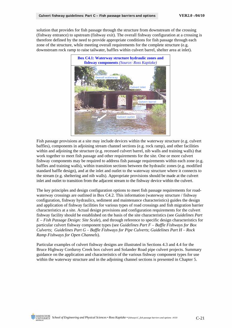
Box C4.1: Waterway structure hydraulic zones and fishway components (Source: Ross Kapitzke)
Fish passage provisions at a site may include devices within the waterway structure (e.g. culvert baffles), components in adjoining stream channel sections (e.g. rock ramp), and other facilities within and adjoining the structure (e.g. recessed culvert barrel, nib walls and training walls) that work together to meet fish passage and other requirements for the site. One or more culvert fishway components may be required to address fish passage requirements within each zone (e.g. baffles and training walls), within transition sections between the hydraulic zones (e.g. modified standard baffle design), and at the inlet and outlet to the waterway structure where it connects to the stream (e.g. sheltering and nib walls). Appropriate provisions should be made at the culvert inlet and outlet to transition from the adjacent stream to the fishway device within the culvert.
The key principles and design configuration options to meet fish passage requirements for road-waterway crossings are outlined in Box C4.2. This information (waterway structure / fishway configuration, fishway hydraulics, sediment and maintenance characteristics) guides the design and application of fishway facilities for various types of road crossings and fish migration barrier characteristics at a site. Actual design provisions and configuration requirements for the culvert fishway facility should be established on the basis of the site characteristics (see Guidelines Part E – Fish Passage Design: Site Scale), and through reference to specific design characteristics for particular culvert fishway component types (see Guidelines Part F – Baffle Fishways for Box Culverts; Guidelines Part G – Baffle Fishways for Pipe Culverts; Guidelines Part H – Rock Ramp Fishways for Open Channels).
Particular examples of culvert fishway designs are illustrated in Sections 4.3 and 4.4 for the Bruce Highway Corduroy Creek box culvert and Solander Road pipe culvert projects. Summary guidance on the application and characteristics of the various fishway component types for use within the waterway structure and in the adjoining channel sections is presented in Chapter 5.
Overall waterway
Culvert barrel
Culvert outlet
Culvert inlet
FlowFlow

VER2.0 -/04/10
School of Engineering and Physical Sciences • Ross Kapitzke • fishways\C_fish passage barriers and options -/4/10 C-22
Culvert fishway guidelines: Part C – Fish passage barriers and options
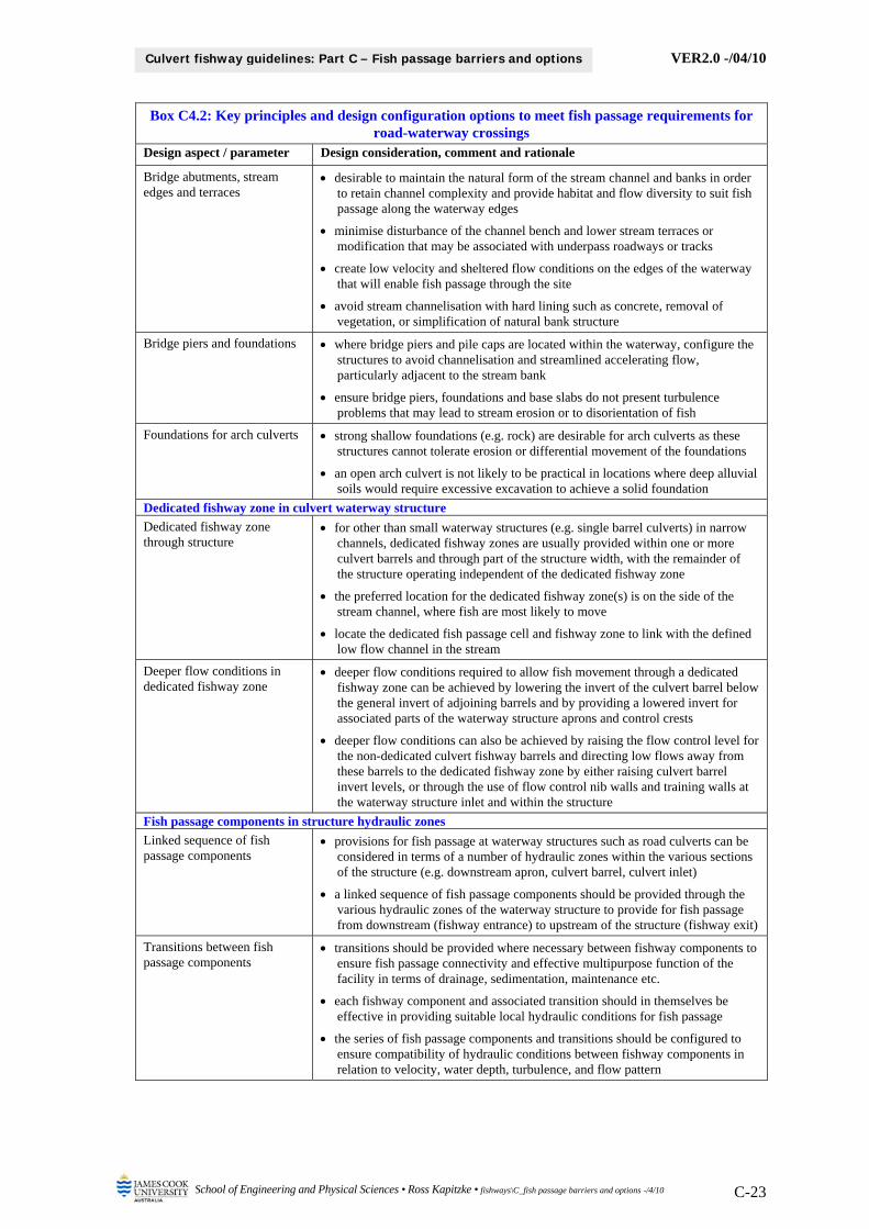
Box C4.2: Key principles and design configuration options to meet fish passage requirements for road-waterway crossings
Design aspect / parameter Design consideration, comment and rationale
Waterway structure / fishway configuration within stream
Stream geomorphic characteristics and crossing location
consider stream geomorphic characteristics and the culvert location and invert levels relative to channel form (e.g. pool or riffle) and stream bed levels
consider the likely trajectory of change in channel form and stream characteristics over time and the possible effects on the waterway and fishway structure (e.g. meander migration, stream bed down-cutting)
retain natural channel form and function (e.g. pool / riffle sequence) and integrate structure within adjoining stream reaches
Stream processes and waterway structure effects
take account of the dynamic nature of the stream and the ecosystem processes applying for instream and riparian zones of the waterway
take account of human – environment interaction for the waterway structure and potential impacts on the biophysical environment
consider location of the fishway in relation to fish movement and aquatic habitat in adjoining reaches, and provide flow and aquatic fauna connectivity between waterway segments upstream and downstream of structure
Grade control in reach adjoining waterway structure
Grade control structure to raise tailwater levels at waterway structure
grade control structures (e.g. rock ramps) can be used at a culvert waterway structure or in adjoining downstream channel sections to overcome fish migration barriers at the structure by raising the tailwater level at the structure outlet
grade control structures incorporated into the adjoining stream reach to raise tailwater levels at the culvert outlet must be ramp or other structure types that, in themselves, provide for fish passage
grade control options to overcome water surface drop at a culvert outlet include a full width stand alone ramp structure in the downstream channel, a full width ramp at the outlet, or a partial width ramp at the outlet to serve a dedicated fishway zone in the culvert
a full width or partial width ramp fishway may also be used at the inlet to road culverts to overcome a steep upstream channel section leading into the culverts, or a drop in water level at control type inlet structures
Grade control in degraded channel section
grade control structures (e.g. rock ramps) can be used in degraded channels to serve a dual-purpose role of erosion control and provisions for fish passage
rock ramp grade control structures prevent unnatural headward erosion or knick-point progression, thereby limiting channel deepening, undercutting of banks, generation of sediment downstream, and infrastructure damage
Grade control in conjunction with lowered culvert invert
provisions for grade control to prevent headward erosion of the stream bed can be made at culvert inlets and outlets where a lowered invert is used for a dedicated culvert fishway barrel or for other components within the structure
grade control ramps or other components incorporated into the waterway structure to link between lowered culvert invert levels and adjoining stream bed levels should be configured to allow fish passage into and out of the structure
Bridge and arch culvert crossings
Encroachment and alteration to stream channel
avoid encroachment of a bridge or arch culvert structure on the waterway cross section, thereby avoiding alteration to natural stream flow conditions
desirable that bridge and arch culverts span the waterway without significant restriction to the channel or alteration to the stream bed or bank configuration
desirable in some circumstances that bridge abutments and associated road embankments are clear from the top of the stream bank in order to reduce the hydraulic obstruction to the waterway and to provide continuous riparian habitat and terrestrial fauna connectivity on the stream banks
VER2.0 -/04/10
School of Engineering and Physical Sciences • Ross Kapitzke • fishways\C_fish passage barriers and options -/4/10 C-23
Culvert fishway guidelines: Part C – Fish passage barriers and options
Box C4.2: Key principles and design configuration options to meet fish passage requirements for road-waterway crossings
Design aspect / parameter Design consideration, comment and rationale
Bridge abutments, stream edges and terraces
desirable to maintain the natural form of the stream channel and banks in order to retain channel complexity and provide habitat and flow diversity to suit fish passage along the waterway edges
minimise disturbance of the channel bench and lower stream terraces or modification that may be associated with underpass roadways or tracks
create low velocity and sheltered flow conditions on the edges of the waterway that will enable fish passage through the site
avoid stream channelisation with hard lining such as concrete, removal of vegetation, or simplification of natural bank structure
Bridge piers and foundations where bridge piers and pile caps are located within the waterway, configure the structures to avoid channelisation and streamlined accelerating flow, particularly adjacent to the stream bank
ensure bridge piers, foundations and base slabs do not present turbulence problems that may lead to stream erosion or to disorientation of fish
Foundations for arch culverts strong shallow foundations (e.g. rock) are desirable for arch culverts as these structures cannot tolerate erosion or differential movement of the foundations
an open arch culvert is not likely to be practical in locations where deep alluvial soils would require excessive excavation to achieve a solid foundation
Dedicated fishway zone in culvert waterway structure
Dedicated fishway zone through structure
for other than small waterway structures (e.g. single barrel culverts) in narrow channels, dedicated fishway zones are usually provided within one or more culvert barrels and through part of the structure width, with the remainder of the structure operating independent of the dedicated fishway zone
the preferred location for the dedicated fishway zone(s) is on the side of the stream channel, where fish are most likely to move
locate the dedicated fish passage cell and fishway zone to link with the defined low flow channel in the stream
Deeper flow conditions in dedicated fishway zone
deeper flow conditions required to allow fish movement through a dedicated fishway zone can be achieved by lowering the invert of the culvert barrel below the general invert of adjoining barrels and by providing a lowered invert for associated parts of the waterway structure aprons and control crests
deeper flow conditions can also be achieved by raising the flow control level for the non-dedicated culvert fishway barrels and directing low flows away from these barrels to the dedicated fishway zone by either raising culvert barrel invert levels, or through the use of flow control nib walls and training walls at the waterway structure inlet and within the structure
Fish passage components in structure hydraulic zones
Linked sequence of fish passage components
provisions for fish passage at waterway structures such as road culverts can be considered in terms of a number of hydraulic zones within the various sections of the structure (e.g. downstream apron, culvert barrel, culvert inlet)
a linked sequence of fish passage components should be provided through the various hydraulic zones of the waterway structure to provide for fish passage from downstream (fishway entrance) to upstream of the structure (fishway exit)
Transitions between fish passage components
transitions should be provided where necessary between fishway components to ensure fish passage connectivity and effective multipurpose function of the facility in terms of drainage, sedimentation, maintenance etc.
each fishway component and associated transition should in themselves be effective in providing suitable local hydraulic conditions for fish passage
the series of fish passage components and transitions should be configured to ensure compatibility of hydraulic conditions between fishway components in relation to velocity, water depth, turbulence, and flow pattern

VER2.0 -/04/10
School of Engineering and Physical Sciences • Ross Kapitzke • fishways\C_fish passage barriers and options -/4/10 C-24
Culvert fishway guidelines: Part C – Fish passage barriers and options
Box C4.2: Key principles and design configuration options to meet fish passage requirements for road-waterway crossings
Design aspect / parameter Design consideration, comment and rationale
Tailwater level for fishway components
Tailwater level at structure outlet / fishway entrance
downstream flow conditions should produce tailwater levels at the culvert outlet that drown out the fishway entrance to a water level at or above the flow profile within the fishway under fish passage design flow conditions
raised tailwater conditions are intended to overcome a water surface drop and to avoid adverse hydraulic conditions associated with local acceleration or formation of a hydraulic jump in the vicinity of the entrance to a fishway
raised tailwater conditions in low gradient culvert structures may also improve conditions within the culvert barrel as a result of maintaining a minimum depth of flow and reducing velocities through the structure
Tailwater level at rock ramp grade control structures
configure rock ramp grade control structures at the culvert outlet and within the stream channel so that the downstream apron is submerged at low flow due to ponding within a natural pool or from downstream grade control structures
Fish pathway, flow continuity and attraction flows
Fish pathway through waterway structure / fishway
the structure should provide suitable fishway entrance and exit arrangements that connect fish passage through the structure with the principal fish paths and resting areas in the adjoining stream.
the preferred fish pathway at the crossing is through the outside culvert barrel(s) as this connects directly with anticipated fish pathways along the stream bank(s) – access through fishways on both stream banks is preferred
Flow continuity through waterway structure / fishway
flow continuity should be provided through the complete waterway and fishway structure to allow fish to move along this flow path from downstream to upstream through the structure
flow through the structure should enter the stream downstream of the crossing at a culvert outlet location that attracts the fish to the fishway entrance
Attraction flows for fish passage through structure
provide suitable attraction flows at the waterway structure outlet to allow fish to locate the fishway entrance and move upstream through the fishway
attraction flows should lead fish into dedicated fishway zones where provided in part of the structure, or alternatively attraction flow conditions may be provided across the full fishway width in some fishways (e.g. rock ramps)
attraction flows should be located at the fishway entrance / structure outlet adjacent to the fish accumulation area and fish pathway along the stream bank, and must provide a continuous pathway upstream through the fishway
auxiliary flows may also be provided in sections of the waterway structure adjacent to the dedicated fishway zone to improve attraction flow conditions at the fishway entrance
Attraction flow and transitions between culvert fishway components
transitions between the various culvert fishway components in the structure should provide suitable attraction flows for fish to locate and move upstream to the adjoining fishway component, as well as suitable resting zones for fish in moving upstream between fishway components
Protection of fish at structure inlet / fishway exit
fish should exit the fishway into the stream at a structure inlet location that enables continued travel upstream and ensures that they are not swept downstream through the structure
provide appropriate flow conditions and shelter at the culvert inlet / fishway exit to protect fish and to allow them to readily move away into milder flow conditions in the upstream approach channel
establishing the dedicated fishway zone along the outside edge of the structure allows direct connection with anticipated fish pathways along the stream bank

VER2.0 -/04/10
School of Engineering and Physical Sciences • Ross Kapitzke • fishways\C_fish passage barriers and options -/4/10 C-25
Culvert fishway guidelines: Part C – Fish passage barriers and options
Box C4.2: Key principles and design configuration options to meet fish passage requirements for road-waterway crossings
Design aspect / parameter Design consideration, comment and rationale
Hydraulic conditions to suit fish passage
Fish movement path through fishway structure
where possible, configure fishway components along the outside edge of the waterway structure to provide connectivitiy for fish passage along the edge of the waterway
provide a continuous clear channel through the entire culvert fishway so that fish do not have to swim a curved, tortuous path; baffles should preferably be arranged so that they are straight with no change in cross-section, no curves, no re-entrant ends, or other complexities (McKinley and Webb 1956)
provide a continuous alignment of baffle slots or notches along one side of the culvert in order to provide an uninterrupted line for fish passage along that side rather than forcing fish to alternate from one side to the other and cross the high velocity zone of the fishway (Bates et al. 2003)
Fish movement behaviour and fishway configuration
fishway baffle configurations should provide sufficient space for fish to follow movement paths between baffles and to rest in shelter areas behind baffles (Katopodis 1977)
fish typically use the path of least resistance as they swim upstream, moving against leeward flows for the greatest part of the way, using intermittent short spurts through jet flow as they pass obstacles, and resting in low velocity zones before moving upstream through the jet flow zones (Engel 1974)
fish negotiating baffle fishways with hydraulic barriers and resting places adopt a burst-rest pattern to advance through the culvert in stages, using burst swim mode to pass barriers at the baffles, and prolonged swim mode to travel or rest in regions of lower velocities in pools between the baffles (Ead et al. 2002)
Desirable fishway features for least delay and energy expenditure of fish (McKinley and Webb 1956)
fish going from resting areas through high velocity areas to other resting areas should enter high velocity areas with as little change in direction as possible
resting areas must be large and well placed to allow plenty of room for numbers of fish in each pool
energy dissipation must be complete in each fishway section so that velocities remain the same throughout the length of the fish passage device
minimum depth in each section must be controlled so that fish will be submerged at all times
the flow pattern must be stable with no objectionable whirlpools, hydraulic jumps, standing waves, or other detrimental hydraulic peculiarities
Sediment, debris and maintenance characteristics of culvert fishways
Sediment transport and deposition
depending on the nature of the stream, the substrate material, the culvert and the baffle configuration, suspended sediment and stream bottom materials commonly move into and through a culvert fishway, with some deposition occurring particularly if the culvert invert is below the stream bed
ramp type structures (e.g. rock ramps), sediment may be deposited in the pools between ridges and reduce pool depth in fish resting areas, and debris may be trapped at the slots and affect flow hydraulics and fish passage at the slots
Fishway location and type baffle fishways (e.g. offset baffle) are less likely to be subject to sedimentation if installed in culverts in a riffle situation in a stream where they are subject to high velocity flows rather than in pool situations subject to low velocity flows
conventional roughness type fishways (e.g. spoiler baffle) that lower velocities throughout have a potentially greater tendency for blockage than pool type fishways due to sediment and debris accumulation in the roughened channel
Debris blockage waterway structures and fishways with a tendency to catch woody debris may cause restriction in structure hydraulic capacity and create a fish migration barrier
waterway structures large enough to pass debris through are preferred rather than smaller structures or use of debris control structures such as trash racks that are detrimental to fish passage
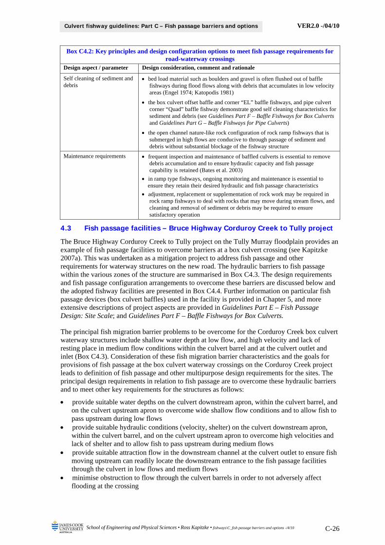
VER2.0 -/04/10
School of Engineering and Physical Sciences • Ross Kapitzke • fishways\C_fish passage barriers and options -/4/10 C-26
Culvert fishway guidelines: Part C – Fish passage barriers and options
Box C4.2: Key principles and design configuration options to meet fish passage requirements for road-waterway crossings
Design aspect / parameter Design consideration, comment and rationale
Self cleaning of sediment and debris
bed load material such as boulders and gravel is often flushed out of baffle fishways during flood flows along with debris that accumulates in low velocity areas (Engel 1974; Katopodis 1981)
the box culvert offset baffle and corner “EL” baffle fishways, and pipe culvert corner “Quad” baffle fishway demonstrate good self cleaning characteristics for sediment and debris (see Guidelines Part F – Baffle Fishways for Box Culverts and Guidelines Part G – Baffle Fishways for Pipe Culverts)
the open channel nature-like rock configuration of rock ramp fishways that is submerged in high flows are conducive to through passage of sediment and debris without substantial blockage of the fishway structure
Maintenance requirements frequent inspection and maintenance of baffled culverts is essential to remove debris accumulation and to ensure hydraulic capacity and fish passage capability is retained (Bates et al. 2003)
in ramp type fishways, ongoing monitoring and maintenance is essential to ensure they retain their desired hydraulic and fish passage characteristics
adjustment, replacement or supplementation of rock work may be required in rock ramp fishways to deal with rocks that may move during stream flows, and cleaning and removal of sediment or debris may be required to ensure satisfactory operation
4.3 Fish passage facilities – Bruce Highway Corduroy Creek to Tully project
The Bruce Highway Corduroy Creek to Tully project on the Tully Murray floodplain provides an example of fish passage facilities to overcome barriers at a box culvert crossing (see Kapitzke 2007a). This was undertaken as a mitigation project to address fish passage and other requirements for waterway structures on the new road. The hydraulic barriers to fish passage within the various zones of the structure are summarised in Box C4.3. The design requirements and fish passage configuration arrangements to overcome these barriers are discussed below and the adopted fishway facilities are presented in Box C4.4. Further information on particular fish passage devices (box culvert baffles) used in the facility is provided in Chapter 5, and more extensive descriptions of project aspects are provided in Guidelines Part E – Fish Passage Design: Site Scale; and Guidelines Part F – Baffle Fishways for Box Culverts.
The principal fish migration barrier problems to be overcome for the Corduroy Creek box culvert waterway structures include shallow water depth at low flow, and high velocity and lack of resting place in medium flow conditions within the culvert barrel and at the culvert outlet and inlet (Box C4.3). Consideration of these fish migration barrier characteristics and the goals for provisions of fish passage at the box culvert waterway crossings on the Corduroy Creek project leads to definition of fish passage and other multipurpose design requirements for the sites. The principal design requirements in relation to fish passage are to overcome these hydraulic barriers and to meet other key requirements for the structures as follows:
provide suitable water depths on the culvert downstream apron, within the culvert barrel, and on the culvert upstream apron to overcome wide shallow flow conditions and to allow fish to pass upstream during low flows
provide suitable hydraulic conditions (velocity, shelter) on the culvert downstream apron, within the culvert barrel, and on the culvert upstream apron to overcome high velocities and lack of shelter and to allow fish to pass upstream during medium flows
provide suitable attraction flow in the downstream channel at the culvert outlet to ensure fish moving upstream can readily locate the downstream entrance to the fish passage facilities through the culvert in low flows and medium flows
minimise obstruction to flow through the culvert barrels in order to not adversely affect flooding at the crossing

VER2.0 -/04/10
School of Engineering and Physical Sciences • Ross Kapitzke • fishways\C_fish passage barriers and options -/4/10 C-27
Culvert fishway guidelines: Part C – Fish passage barriers and options
minimise debris accumulation and sediment deposition within the culvert barrels and provide for ready cleaning and maintenance of the waterway structure
These fish passage requirements have been addressed in the culvert fishway designs for the site, which has involved identification of options and evaluation of suitability of a number of fish passage components within the various zones of the waterway structure. The adopted fishway facilities and their suitability in meeting fish passage requirements for the site are outlined below for each of the hydraulic zones leading from downstream (Zone A) to upstream (Zone D). The adopted fishway configuration for the structures is presented in Box C4.4, and the characteristics of individual fishway component types (baffles) are outlined in Chapter 5. The following material is based principally on the project case study report (Kapitzke 2007a).
Box C4.3: Principal hydraulic barriers to fish passage within culvert zones at Bruce Highway Corduroy Creek box culvert crossing of Tully Murray floodplain (After: Kapitzke 2007a)
Hydraulic barrier type
Zone D: Culvert inlet and upstream
channel
Zone C: Culvert barrel
Zone B: Culvert outlet and
downstream apron
Zone A: Downstream
channel
High velocity Ⓜ Ⓜ Ⓜ
Shallow water depth Ⓛ Ⓛ Ⓛ
Lack of resting place Ⓜ Ⓜ Ⓜ
Excess turbulence
Water surface drop
Legend Ⓛ Low flow condition Ⓜ Medium flow condition
There are no specific requirements to provide fish passage facilities for Zone A – Downstream channel and apron drop-off, as hydraulic conditions do not present a barrier to upstream fish movement in this zone (Box C4.3). Relatively high tailwater conditions provide adequate water depth in low flow conditions, and the requirement to provide suitable attraction flow to lead fish to the culvert outlet from the downstream channel is addressed by providing the low nib walls and training walls to direct low flows through the structure and to concentrate flow at a defined outlet location (Box C4.4). This low flow channel is provided in the end cell for some structures and in the mid cell for other larger structures.
Fish passage requirements for Zone B – Culvert outlet and downstream apron, Zone C – Culvert barrel, and Zone D – Culvert inlet and upstream channel are addressed by providing the corner “EL” baffle fishway within one dedicated culvert cell, and the nib wall and low flow training wall configurations at the culvert inlet and outlet to direct low flows through the adopted cell (Box C4.4). These baffles, which are located on the outside wall of the end cell for some structures and in the mid cell for other larger structures, address the requirements to provide suitable hydraulic conditions (velocity, shelter) through the structure in medium flow conditions. Velocity, shelter and turbulence are satisfactory during low flow, and nib wall and training wall facilities provide suitable water depth by concentrating flow through the dedicated culvert cell.
Culvert inlet and upstream channel
Culvert barrel
Downstream channel
Culvert outlet and downstream apron
Zone D Zone C Zone B Zone A
Multi–cell box culvert
Flow Low flow
Medium flow

VER2.0 -/04/10
School of Engineering and Physical Sciences • Ross Kapitzke • fishways\C_fish passage barriers and options -/4/10 C-28
Culvert fishway guidelines: Part C – Fish passage barriers and options
The low flow nib walls (400 mm high) extend across the non-low flow cells at the culvert inlet and direct shallow flows into the dedicated fishway barrel (Box C4.4). Low flow training walls (400 mm high) connect these nib walls to the box culvert cells at the culvert inlet, and extend over the downstream outlet apron of the culvert. Notches (100 mm deep) are provided in the nib walls at the culvert inlet to provide flow connectivity through the non-fishway cells, and to allow upstream passage for fish that move into the relatively calm conditions in the non-fishway cell, and might otherwise be trapped downstream of the nib wall. Flow through the notches provides attraction flow for these fish to pass upstream through the notch.
4.4 Fish passage facilities – University Creek Solander Road pipe culvert
The Solander Road project on University Creek provides an example of fish passage facilities to overcome barriers at a pipe culvert crossing (see Kapitzke 2007c). This was undertaken as a remediation project to address fish passage and other requirements for an existing structure. The hydraulic barriers to fish passage within the various zones of the structure are summarised in Box C4.5 The design requirements and fish passage configuration arrangements to overcome these barriers are discussed below and adopted fishway facilities are presented in Box C4.6. Further information on particular fish passage devices (pipe culvert baffles, rock ramp cascade) used in the facility is provided in Chapter 5, and more extensive descriptions of project aspects are provided in Guidelines Part E – Fish Passage Design: Site Scale; Guidelines Part G – Baffle Fishways for Pipe Culverts; and Guidelines Part H – Rock Ramp Fishways for Open Channels.
The principal fish migration barrier problems to be overcome at the Solander Road crossing include high velocity, shallow water depth, lack of resting place, excess turbulence, and water surface drop within the various hydraulic zones of the structure in low flow and medium flow conditions (Box C4.5). Consideration of these fish migration barrier characteristics and the goals for fish passage provisions (which focus on low flow conditions) at the Solander Road pipe culvert leads to definition of fish passage and other multipurpose design requirements for the site. The principal design requirements in relation to fish passage are to overcome these hydraulic barriers and to meet other key requirements for the structures as follows:
provide suitable hydraulic conditions (velocity, shelter, turbulence) in the downstream channel to overcome water surface drop and other adverse conditions and to allow fish to pass upstream during low flows
provide suitable hydraulic conditions (velocity, flow depth, shelter) at the culvert outlet and on the downstream apron to overcome high velocities, shallow flow depth and lack of shelter and to allow fish to pass upstream during low flows
provide suitable hydraulic conditions (velocity, shelter, turbulence) within the culvert barrel and at the culvert inlet to overcome high velocities, lack of shelter and turbulence to allow fish to pass upstream during low flows
provide suitable shelter conditions at the culvert inlet and in the upstream channel to allow fish that have passed through the downstream fishway sections to exit the pipe and move freely away into the stream during low flows
provide flow continuity through all fishway zones and a continuous fish pathway and attraction flow to allow fish to readily locate the downstream entrance to the fish passage facilities through the culvert and to move upstream through the fishway during low flows
minimise obstruction to flow through the culvert barrels in order to not adversely affect flooding at the crossing
minimise debris accumulation and sediment deposition within the culvert barrels and provide for ready cleaning and maintenance of the waterway structure
maintain integrity of the waterway crossing structure and provide for remediation of existing erosion damage and undermining on the downstream side of the causeway and culvert
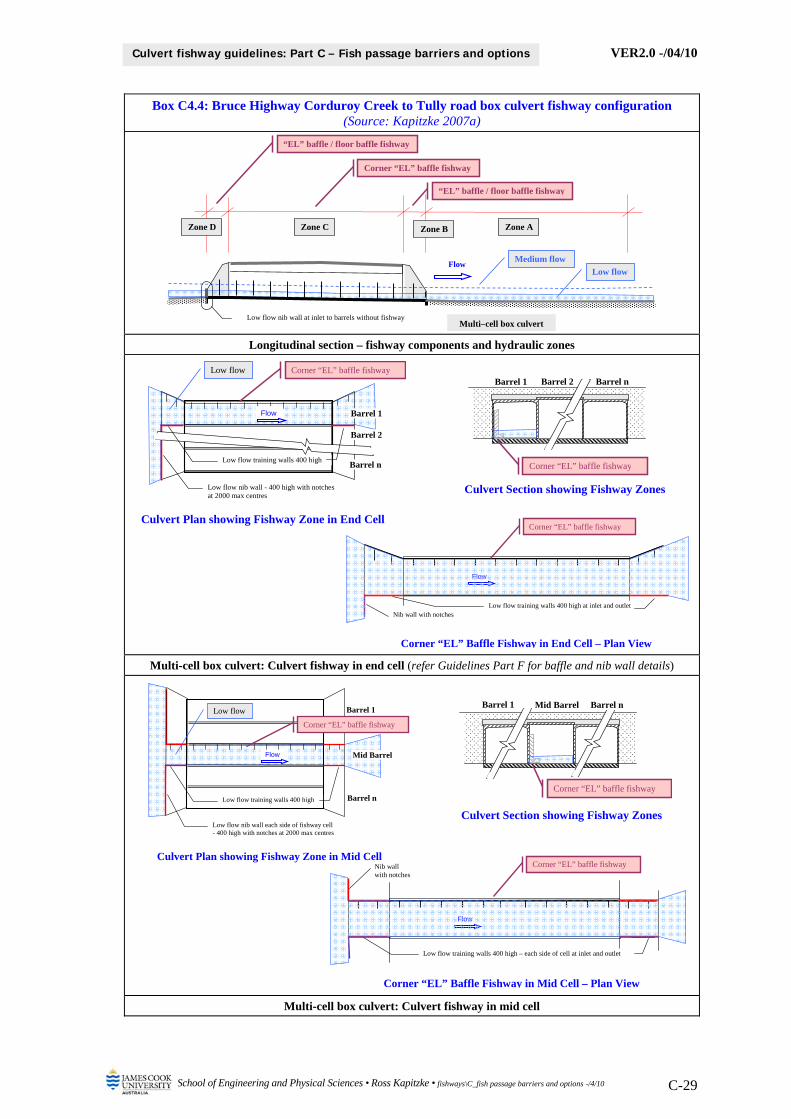
VER2.0 -/04/10
School of Engineering and Physical Sciences • Ross Kapitzke • fishways\C_fish passage barriers and options -/4/10 C-29
Culvert fishway guidelines: Part C – Fish passage barriers and options
Box C4.4: Bruce Highway Corduroy Creek to Tully road box culvert fishway configuration (Source: Kapitzke 2007a)
Longitudinal section – fishway components and hydraulic zones
Multi-cell box culvert: Culvert fishway in end cell (refer Guidelines Part F for baffle and nib wall details)
Multi-cell box culvert: Culvert fishway in mid cell
Mid Barrel Barrel 1 Barrel n
Corner “EL” baffle fishway
Barrel 2 Barrel n Barrel 1
Corner “EL” baffle fishway
Zone D Zone C Zone B Zone A
Multi–cell box culvert
Flow Low flow
Medium flow
Corner “EL” baffle fishway
Low flow nib wall at inlet to barrels without fishway
“EL” baffle / floor baffle fishway
“EL” baffle / floor baffle fishway
Culvert Plan showing Fishway Zone in End Cell
Barrel 2
Barrel n
Barrel 1Flow
Corner “EL” baffle fishway
Low flow training walls 400 high
Low flow nib wall - 400 high with notches at 2000 max centres
Low flow
Corner “EL” Baffle Fishway in End Cell – Plan View
Flow
Low flow training walls 400 high at inlet and outlet Nib wall with notches
Corner “EL” baffle fishway
Culvert Section showing Fishway Zones
Culvert Section showing Fishway Zones
Culvert Plan showing Fishway Zone in Mid Cell
Mid Barrel
Barrel n
Barrel 1
Flow
Low flow nib wall each side of fishway cell - 400 high with notches at 2000 max centres
Low flow training walls 400 high
Corner “EL” baffle fishway
Low flow
Corner “EL” Baffle Fishway in Mid Cell – Plan View
Flow
Low flow training walls 400 high – each side of cell at inlet and outlet
Nib wall with notches
Corner “EL” baffle fishway

VER2.0 -/04/10
School of Engineering and Physical Sciences • Ross Kapitzke • fishways\C_fish passage barriers and options -/4/10 C-30
Culvert fishway guidelines: Part C – Fish passage barriers and options
The fish passage requirements for the Solander Road crossing have been addressed in the culvert fishway designs for the site, which has involved identification of options and evaluation of suitability of a number of fish passage components within the various zones of the waterway structure. The adopted fishway facilities and their suitability in meeting fish passage requirements for the site are outlined below for each of the hydraulic zones leading from downstream (Zone A) to upstream (Zone D). The adopted fishway configuration for the structure is presented in Box C4.6, and the characteristics of individual fishway component types (baffles, rock ramp cascades) are outlined in Chapter 5. The following material is based principally on the project case study report (Kapitzke 2007c).
The adverse hydraulic conditions for upstream fish passage extend through all zones of the waterway structure at this site (Box C4.5). Because the conditions are severe in medium flow conditions, particularly through the culvert barrel and at the culvert outlet, the design goals focus on overcoming hydraulic barriers in low flow conditions. The fish passage facilities comprise components within each of the waterway structure zones, with the need for careful configuration of fishway devices to provide for integrated function of the facility to provide for fish passage upstream through all zones. Requirements for erosion protection and environmental remediation of the site are also to be integrated into the fish passage facilities.
Box C4.5: Principal hydraulic barriers to fish passage within culvert zones at Solander Road pipe culvert causeway crossing of University Creek (After: Kapitzke 2007c)
Hydraulic barrier type
Zone D: Culvert inlet and upstream
channel
Zone C: Culvert barrel
Zone B: Culvert outlet and
downstream apron
Zone A: Downstream
channel
High velocity ⓁⓂ ⓁⓂ ⓁⓂ Ⓜ
Shallow water depth Ⓛ
Lack of resting place ⓁⓂ ⓁⓂ ⓁⓂ
Excess turbulence ⓁⓂ ⓁⓂ Ⓜ ⓁⓂ
Water surface drop Ⓛ
Legend Ⓛ Low flow condition Ⓜ Medium flow condition
For Zone A – Downstream channel and apron drop-off, the requirements to overcome excess turbulence and the water surface drop at the downstream end of the culvert apron are addressed by providing the rock ramp cascade fishway in the channel (Box C4.6). This provides a series of pools and low riffle type structures to suit upstream fish passage in the stream and raises the tailwater level at the downstream end of the apron during low flow. The rock ramp cascades are integrated with rock protection works that provide for erosion control and site remediation.
Fish passage requirements for Zone B – Culvert outlet and downstream apron are addressed by providing the offset baffle fishway on the culvert downstream apron slab (Box C4.6). This baffle structure increases flow depth on the apron slab, and provides diverse flow conditions during low flows that provide low velocities, resting areas, attraction flows and continuous flow paths for fish moving upstream to the pipe culvert outlet.
Culvert inlet and upstream channel
Culvert barrel Downstream channel and apron drop-off
Culvert outlet and downstream apron
Zone D Zone C Zone B Zone A
4–Barrel pipe culvert, causeway and apron
Flow
Low flow Medium flow

VER2.0 -/04/10
School of Engineering and Physical Sciences • Ross Kapitzke • fishways\C_fish passage barriers and options -/4/10 C-31
Culvert fishway guidelines: Part C – Fish passage barriers and options
Within Zone C – Culvert barrel, fish passage requirements are addressed by providing the offset baffle fishway and the corner “Quad” baffle fishways within each of two culvert barrels (Box C4.6). These devices are placed to evaluate comparative performance, and are intended to provide suitable hydraulic conditions (velocity, shelter, turbulence) for upstream fish passage through the culvert barrels during low flows. The baffle devices within the pipe barrels abut the baffle fishway facilities on the downstream apron, but the fish passage effectiveness across this junction and the need for transition fishway structures between the adjoining fishway zones requires careful attention in waterway structures such as this with complex hydraulic conditions.
Limited fish passage provisions are made within Zone D – Culvert inlet and upstream channel. Large boulders are placed in the stream channel at the inlet to the pipe barrels containing the fishway devices. These fishway exit works address the need to provide shelter for fish exiting the pipe culvert barrels and moving upstream through the stream channel. A low flow nib wall is provided across the inlet to those pipe barrels without fishway facilities in order to direct low flows downstream through the dedicated barrels. Once again careful attention is to be given to the configuration of the inlet nib wall and the need for transition fishway structures to link these and other fishway facilities at the culvert inlet with those within the adjoining culvert barrels.

VER2.0 -/04/10
School of Engineering and Physical Sciences • Ross Kapitzke • fishways\C_fish passage barriers and options -/4/10 C-32
Culvert fishway guidelines: Part C – Fish passage barriers and options
Box C4.6: Solander Road pipe culvert fishway configuration (Source: Kapitzke 2007c)
General arrangement showing fishway components and protection works
Longitudinal section – fishway components and hydraulic zones (refer Guidelines Part H for rock ramp details)
Configuration of pipe culvert and apron – fishway components (refer Guidelines Part G for baffle details)
Solander Road
Culvert inlet / fishway exit works Bypass fishway culvert and exit channel (future)
4–Barrel pipe culvert and causeway
NFlow
Rock ramp / cascade fishway Rock ramp ridge / cascade
Table drain and bypass entrance channel / rock ramp fishway
Rock ramp ridges
University Creek
Apron – offset baffle fishway
Pipe baffle fishway – offset / corner
Legend – rock protection
Ridge Rock
Cascade Rock
Batter Rock
Apron Rock
Low flow nib wall at inlet to barrels without fishways
Low flow
Culvert inlet / fishway exit works
Pipe baffle fishway – offset / corner
Rock ramp / cascade fishway Apron – offset baffle fishway
Zone D Zone C Zone B Zone A
4–Barrel pipe culvert, causeway and apron
Rock ramp ridges / cascades
Flow Low flow
Culvert Plan View
Solander Road 4–Barrel pipe culvert and causeway
Barrel 1
Barrel 2
B
AFlow
Low flow nib wall at inlet to barrels without fishways
Apron – offset baffle fishway
Offset baffle fishway
Corner baffle fishway
Section B-B: Culvert Looking upstream
1200 dia. pipes
Corner baffle fishway
Offset baffle fishway
Apron – offset baffle fishway
Section A-A: Culvert and apron
Flow
Low flow nib wall at inlet to barrels without fishways
Pipe baffle fishway – offset / corner
Apron – offset baffle fishway

VER2.0 -/04/10
School of Engineering and Physical Sciences • Ross Kapitzke • fishways\C_fish passage barriers and options -/4/10 C-33
Culvert fishway guidelines: Part C – Fish passage barriers and options
5 APPLICATION AND CHARACTERISTICS OF FISHWAY COMPONENTS
Provisions for fish passage at a waterway structure will commonly include several fishway components incorporated within the various hydraulic zones of the structure to overcome fish migration barrier conditions. This may include, for example, baffle or other fishway devices within the culvert barrel and adjoining aprons, rock ramp type grade control structures in adjacent stream channel sections to provide suitable tailwater conditions for the crossing, and ancillary facilities such as nib walls and low flow channels to direct flow through a dedicated fishway zone in the structure. Hydraulic barriers to fish passage are described and categorised in Chapter 2, and the overall configuration options for fish passage facilities that can be used to achieve the desired fish passage requirements at the structure are outlined in Chapter 4. The material presented here relates primarily to the hydraulic design approach for culvert fishways outlined in Chapter 3.
This Chapter 5 describes the application and characteristics of a number of fish passage component types that can be used as part of the fishway facility within the waterway structure and in the adjoining stream channel. The summary information presented here relates to several fishway types for which detailed configuration and performance characteristics are provided in other Guideline documents (Part F – Baffle Fishways for Box Culverts; Part G – Baffle Fishways for Pipe Culverts; Part H – Rock Ramp Fishways for Open Channels). Possible applications of these fishway component types for particular hydraulic zones of road-waterway crossings are identified (Box C5.1), and the configuration, application and performance characteristics of the fishways are summarised (Box C5.2). Other alternative fishway types may also be used to meet fish passage requirements within these waterway structure zones, and other fishway components and configuration aspects may be required within other zones of the waterway structure (e.g. culvert outlet and downstream apron).
Where several alternatives are available, an evaluation should be undertaken of alternative fishway component types and their suitability in meeting multipurpose requirements (transport, drainage, fish passage, amenity) for the waterway structure and fishway facilities (see Guidelines Part E – Fish Passage Design: Site Scale). This may involve either mitigation measures to address potential fish migration barrier problems at new structures (e.g. incorporating rock ramps downstream of the crossing for raised tailwater), or remediation measures to overcome fish passage problems as retrofits for existing structures (e.g. fitting baffles within the culvert barrel). Several waterway crossing and fish passage design options may be available to address the design goals, requiring evaluation of component types and overall fishway configurations prior to adoption. Integrated solutions are required to address fish passage and other multipurpose objectives for the waterway structure.

VER2.0 -/04/10
School of Engineering and Physical Sciences • Ross Kapitzke • fishways\C_fish passage barriers and options -/4/10 C-34
Culvert fishway guidelines: Part C – Fish passage barriers and options
Box C5.1: Possible application of fishway component types for particular hydraulic zones of road-waterway crossings
Fishway component type 1
Zone D: Culvert inlet and upstream
channel
Zone C: Culvert barrel
Zone B: Culvert outlet and
downstream apron
Zone A: Downstream
channel Baffle fishways for box culverts (Guidelines Part F)
Offset baffle
Corner “EL” baffle Baffle fishways for pipe culverts (Guidelines Part G)
Offset baffle
Corner “Quad” baffle Rock ramp fishways for open channels (Guidelines Part H)
Rock ramp
Rock ramp / Cascade
Example culvert configuration, flow profiles and hydraulic zones: Box culvert
Example culvert configuration, flow profiles and hydraulic zones: Pipe culvert and causeway
Notes 1 Other alternative fishway types may also be used to meet fish passage requirements within these waterway structure zones. Integrated solutions are required to address fish passage and other multipurpose objectives for the waterway crossing.
Culvert inlet and upstream channel
Culvert barrel
Downstream channel
Culvert outlet and downstream apron
Zone D Zone C Zone B Zone A
Multi–cell box culvert
Flow Low flow
Medium flow
Culvert inlet and upstream channel
Culvert barrel Downstream channel and apron drop-off
Culvert outlet and downstream apron
Zone D Zone C Zone B Zone A
Multi–barrel pipe culvert, causeway and apron
Flow
Low flow Medium flow
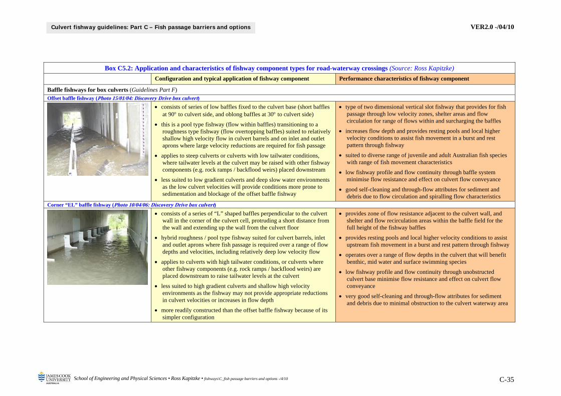
VER2.0 -/04/10
School of Engineering and Physical Sciences • Ross Kapitzke • fishways\C_fish passage barriers and options -/4/10 C-35
Culvert fishway guidelines: Part C – Fish passage barriers and options
Box C5.2: Application and characteristics of fishway component types for road-waterway crossings (Source: Ross Kapitzke)
Configuration and typical application of fishway component Performance characteristics of fishway component
Baffle fishways for box culverts (Guidelines Part F) Offset baffle fishway (Photo 15/01/04: Discovery Drive box culvert)
consists of series of low baffles fixed to the culvert base (short baffles at 90 to culvert side, and oblong baffles at 30 to culvert side)
this is a pool type fishway (flow within baffles) transitioning to a roughness type fishway (flow overtopping baffles) suited to relatively shallow high velocity flow in culvert barrels and on inlet and outlet aprons where large velocity reductions are required for fish passage
applies to steep culverts or culverts with low tailwater conditions, where tailwater levels at the culvert may be raised with other fishway components (e.g. rock ramps / backflood weirs) placed downstream
less suited to low gradient culverts and deep slow water environments as the low culvert velocities will provide conditions more prone to sedimentation and blockage of the offset baffle fishway
type of two dimensional vertical slot fishway that provides for fish passage through low velocity zones, shelter areas and flow circulation for range of flows within and surcharging the baffles
increases flow depth and provides resting pools and local higher velocity conditions to assist fish movement in a burst and rest pattern through fishway
suited to diverse range of juvenile and adult Australian fish species with range of fish movement characteristics
low fishway profile and flow continuity through baffle system minimise flow resistance and effect on culvert flow conveyance
good self-cleaning and through-flow attributes for sediment and debris due to flow circulation and spiralling flow characteristics
Corner “EL” baffle fishway (Photo 10/04/06: Discovery Drive box culvert)
consists of a series of “L” shaped baffles perpendicular to the culvert wall in the corner of the culvert cell, protruding a short distance from the wall and extending up the wall from the culvert floor
hybrid roughness / pool type fishway suited for culvert barrels, inlet and outlet aprons where fish passage is required over a range of flow depths and velocities, including relatively deep low velocity flow
applies to culverts with high tailwater conditions, or culverts where other fishway components (e.g. rock ramps / backflood weirs) are placed downstream to raise tailwater levels at the culvert
less suited to high gradient culverts and shallow high velocity environments as the fishway may not provide appropriate reductions in culvert velocities or increases in flow depth
more readily constructed than the offset baffle fishway because of its simpler configuration
provides zone of flow resistance adjacent to the culvert wall, and shelter and flow recirculation areas within the baffle field for the full height of the fishway baffles
provides resting pools and local higher velocity conditions to assist upstream fish movement in a burst and rest pattern through fishway
operates over a range of flow depths in the culvert that will benefit benthic, mid water and surface swimming species
low fishway profile and flow continuity through unobstructed culvert base minimise flow resistance and effect on culvert flow conveyance
very good self-cleaning and through-flow attributes for sediment and debris due to minimal obstruction to the culvert waterway area

VER2.0 -/04/10
School of Engineering and Physical Sciences • Ross Kapitzke • fishways\C_fish passage barriers and options -/4/10 C-36
Culvert fishway guidelines: Part C – Fish passage barriers and options
Box C5.2: Application and characteristics of fishway component types for road-waterway crossings (Source: Ross Kapitzke)
Configuration and typical application of fishway component Performance characteristics of fishway component
Baffle fishways for pipe culverts (Guidelines Part G) Offset baffle fishway (Photo 11/04/06: Solander Road pipe culvert)
consists of series of low baffles fixed to the culvert base (short baffles at 90 to culvert side, and oblong baffles at 30 to culvert side)
this is a pool type fishway (flow within baffles) transitioning to roughness type fishway (flow overtopping baffles) suited to relatively shallow high velocity flow in culvert barrels where large velocity reductions are required for fish passage
applies to steep culverts or culverts with low tailwater conditions, where tailwater levels at the culvert may be raised with other fishway components (e.g. rock ramps / backflood weirs) placed downstream
less suited to low gradient culverts and deep slow water environments as the low culvert velocities will provide conditions more prone to sedimentation and blockage of the offset baffle fishway
less suited to pipe culverts than to box culverts due to less favourable flow conditions for fish passage within and submerging baffles
type of two dimensional vertical slot fishway that provides for fish passage through low velocity zones, shelter areas and flow circulation for range of flows within and surcharging the baffles
increases flow depth and provides resting pools and local higher velocity conditions to assist fish movement in a burst and rest pattern through fishway
low fishway profile and flow continuity through baffle system minimises flow resistance and effect on culvert flow conveyance
good self-cleaning and through-flow attributes for sediment and debris due to flow circulation and spiralling flow characteristics
Corner “Quad” baffle fishway (Photo 11/04/06: Solander Road pipe culvert)
consists of a series of quad shaped baffles perpendicular to the culvert wall in the lower quadrant of the culvert barrel, extending up the wall to close to half pipe diameter, with pipe invert unobstructed by baffles
this hybrid roughness / pool type fishway is suited for culvert barrels where fish passage is required over a range of flow depths and velocities, including relatively deep low velocity flow
applies to culverts with high tailwater conditions, or culverts where other fishway components (e.g. rock ramps / backflood weirs) are placed downstream to raise tailwater levels at the culvert
less suited to high gradient culverts and shallow high velocity environments as the fishway may not provide appropriate reductions in culvert velocities or increases in flow depth
more readily constructed than the offset baffle fishway because of its simpler configuration
provides zone of flow resistance adjacent to the culvert wall, and shelter and flow recirculation areas within the baffle field for the full height of the fishway baffles
provides resting pools and local higher velocity conditions to assist upstream fish movement in a burst and rest pattern through fishway
operates over a range of flow depths in the culvert that will benefit benthic, mid water and surface swimming species
flow continuity provided through unobstructed culvert base minimises flow resistance and effect on culvert flow conveyance
very good self-cleaning and through-flow attributes for sediment and debris as culvert invert and barrel side not obstructed by baffles

VER2.0 -/04/10
School of Engineering and Physical Sciences • Ross Kapitzke • fishways\C_fish passage barriers and options -/4/10 C-37
Culvert fishway guidelines: Part C – Fish passage barriers and options
Box C5.2: Application and characteristics of fishway component types for road-waterway crossings (Source: Ross Kapitzke)
Configuration and typical application of fishway component Performance characteristics of fishway component
Rock ramp fishways for open channels (Guidelines Part H) Rock ramp fishway (Photo 25/01/05: Douglas Arterial Road bridge crossing)
low gradient structure comprising a series of transverse rock ridges, with short pool sections between the ridges to create a series of miniature pools and riffles to mimic natural stream flow conditions
standard rock ramp fishway comprises a series of ridges at 2 metre intervals, with a localised 100 mm drop (through V-slots between rocks) at ridges and an overall longitudinal slope of 1 in 20
suited for use as free standing grade control structures in an open channel or as attached structures to the inlet or outlet of road culverts or downstream of weirs or barrier walls
used in open channel applications to overcome water surface drops / steep waterway beds, and in channel sections downstream of road culverts to raise tailwater levels at the culvert
used as attached structures to overcome water surface drops / steep waterway beds either at culvert inlets or outlets or below low-level barriers such as weirs and barrier / grade control structures
nature-like fishway that provides for fish passage through low velocity zones and shelter areas for range of flows within and surcharging the rock ridges
provides multiple interconnected pathways for fish passage using continuous swimming or a burst and rest swimming pattern
irregular nature of fishway and the diversity of hydraulic conditions (water velocities and depths) provide passage for a variety of fish species and sizes, including juveniles and adults
the open channel fishway configuration provides little obstruction to flow and has little appreciable effect on flow conveyance
tendency for self-cleaning and through-flow attributes for sediment and debris due to the open channel nature-like rock configuration that is submerged at high flows
pool depths in fish resting areas between ridges may be reduced through sediment deposition, and flow hydraulics and fish passage may be affected by debris trapping at rock ridge slots
Rock ramp / cascade fishway (Photo 29/01/06: Solander Road pipe culvert and causeway)
low gradient structure in an open channel comprising a series of free standing rock cascade grade control structures with pool sections between them to create a series of pools and riffles to mimic natural stream flow conditions
each rock cascade comprises a single row of transverse ridge rocks and a series of cascade rocks downstream of and abutting the ridge, with a localised longitudinal gradient of about 1 in 9 over the length of the cascade section
rock ramp cascades with a localised drop of 400 mm are spaced along the stream reach to pool water back to adjoining cascade structures and to provide an overall gradient of steeper than 1 in 20 in the reach
nature-like fishway that provides for fish passage between pools and through cascade structures via low velocity zones and shelter areas for range of flows within and surcharging the rock cascades
provides resting areas for fish in large pools, and local conditions at cascades to assist fish movement in burst and rest swimming pattern, but more severe and lower diversity of hydraulic conditions than conventional rock ramp fishway
the open channel fishway configuration provides little obstruction to flow and has little appreciable effect on flow conveyance
tendency for self-cleaning and through-flow attributes for sediment and debris due to the open channel nature-like rock configuration that is submerged at high flows
fish passage may be affected by debris trapping at rock ridge slots

VER2.0 -/04/10
School of Engineering and Physical Sciences • Ross Kapitzke • fishways\C_fish passage barriers and options -/4/10 C-38
Culvert fishway guidelines: Part C – Fish passage barriers and options
6 FISH PASSAGE PROVISIONS AT TEMPORARY ROAD CROSSINGS
Temporary road-waterway crossings established during construction of a road project may represent a barrier to fish movement through the site unless consideration is given to fish movement requirements during the construction period and appropriate provisions are made for fish passage as part of the temporary road crossing facility. The extent of the fish migration barrier problem and the provisions to be made for fish passage depend primarily on:
nature of the waterway or fish movement corridor (see Guidelines Part E – Fish Passage Design: Site Scale)
significance of the fish community and the fish movement characteristics for the site (see Guidelines Part E – Fish Passage Design: Site Scale )
characteristics of the temporary road crossing (e.g. pipe culvert, earth bund, bridge) timing (duration and season) during which the temporary crossing is present in the waterway aquatic fauna connectivity goals, fish passage design objectives and design requirements for
the temporary crossing (e.g. design flow range, fish passage effectiveness, multipurpose design requirements)
This chapter provides an outline of the potential fish migration barriers that may be present at the various types of temporary road crossing facilities. Fish passage design requirements and mitigation measures to overcome these barriers are outlined, and case study illustrations are provided of fish migration barriers and provisions to overcome these barriers for the University Creek Douglas Arterial Road and Bruce Highway Corduroy Creek projects (Box C6.1).
Box C6.1: Illustration of potential fish migration barrier problems and mitigation measures associated with temporary road-waterway crossings for Douglas Arterial Road project and Bruce Highway Corduroy Creek project (Source: Ross Kapitzke)
High velocity barriers to fish and erosion at outlet of small diameter bypass pipe culvert
beneath temporary road crossing for Douglas Arterial Road crossing of University Creek
(17/01/04)
Temporary bund installed with major waterway opening retained during
construction of new bridge crossing of the Tully River for Bruce Highway Corduroy
Creek project (21/08/07)
6.1 Fish migration barriers at temporary road-waterway crossings
Temporary crossings may be established as part of new road projects involving or more waterway crossings of the road corridor, or on remediation projects for existing roads involving replacement, repair or reconstruction of individual crossings. Temporary crossings or waterway modifications may present the following potential fish migration barriers:
side track detour crossing of waterway or diversion channel off-site from primary waterway crossing (e.g. upstream or downstream of reconstructed crossing on existing alignment)
construction access track and/or construction pad or bund crossing of waterway or diversion channel at primary waterway crossing (e.g. new road alignment with traffic detour off-site)
modification or obstruction to waterway at the crossing site (e.g. encroachment or blockage of waterway associated with construction works)

VER2.0 -/04/10
School of Engineering and Physical Sciences • Ross Kapitzke • fishways\C_fish passage barriers and options -/4/10 C-39
Culvert fishway guidelines: Part C – Fish passage barriers and options
adverse conditions in diversion channel constructed at the crossing site (e.g. channelisation)
Drainage provisions that are made at a side track or construction track temporary waterway crossing are typically developed to a lower standard (e.g. smaller culvert waterway area, low embankment subject to overtopping, minimal erosion protection works) than those that would be provided as part of permanent drainage facilities for the site. Whilst some temporary crossings may be in place only during dry season conditions, most temporary crossings will be subject to a range of flow conditions, including periods of flow when fish may be migrating in the waterway. Depending on the duration of the installation and the type and configuration of the crossing structure used (e.g. ford, culvert, bridge), many temporary waterway crossing structures may represent a fish migration barrier problem during critical fish migration flows in the waterway.
Construction pad or bund crossings of a waterway or diversion channel may be provided where a working platform is required for construction activities such as pile driving, foundation preparation, manoeuvre and installation of structural members, formwork and scaffolding support. Drainage provisions at these construction pads or bunds may include low capacity culverts installed through the embankment, drainage inverts to concentrate low flows over the embankment at defined locations, or discontinuous embankment sections with gaps provided to encompass the main waterway channel. Development and use of these embankment structures may be programmed for dry season conditions, but construction of the crossing often extends through periods of substantial stream flow, including flow periods when fish may be migrating.
Where the new road crossing drainage structure is constructed within the waterway channel, structure components (e.g. culvert walls, bridge abutments and piers) and construction facilities (e.g. formwork, scaffolding) may encroach on the waterway, obstruct flow and produce adverse flow conditions that represent fish migration barrier problems at the structure. In situations where an alternative diversion channel or low flow drainage culvert is not provided, these obstructions to the waterway channel may represent critical fish migration barriers at the site.
Diversion channels that are sometimes provided to direct flow away from the waterway crossing structure may in themselves cause problems as a result of conventional open channel design that increases flow velocity, reduces flow depth, reduces channel roughness and substrate complexity, and causes bed and bank erosion that leads to water surface drops in the channel. Diversion channels often follow a shorter alignment than the natural stream channel at the site, and the steeper gradient and regular channel profile commonly produce adverse hydraulic conditions that represent fish migration barrier problems.
The various temporary crossing configurations and waterway modifications outlined above may lead to fish migration barrier problems associated with adverse hydraulic conditions within the various zones (e.g. inlet, outlet, downstream channel) of the waterway crossings or channel sections. These potential fish migration barrier problems are outlined here in terms of the principal types of hydraulic barriers (high velocity; reduced flow depth; lack of resting place or shelter; excess turbulence; water surface drop) identified and described in Chapter 2. The likely occurrence of these hydraulic barriers within the various temporary crossings and waterway modifications, and the various types of hydraulic barriers that may occur at these structures are identified, described and illustrated in Box C6.2.

VER2.0 -/04/10
School of Engineering and Physical Sciences • Ross Kapitzke • fishways\C_fish passage barriers and options -/4/10 C-40
Culvert fishway guidelines: Part C – Fish passage barriers and options
Box C6.2: Common occurrence and description of principal hydraulic barriers to fish passage within various temporary crossing configurations and waterway modifications (See Chapter 2 for
description of barriers; Source: Ross Kapitzke)
Ford or level
crossing
Pipe or box culvert
Bridge or spanning
deck
Embank’t, pad or bund
Channel encroach
Diversion channel
High velocity Shallow water depth
Lack of resting place
Excess turbulence
Water surface drop Ford or level crossing (Photo 17/06/08: Low level gravel and rock causeway Little Stuart Creek, Townsville)
a ford or level crossing is a low embankment used to provide for vehicle access across the waterway under very low flow conditions
this type of crossing may be used off-site in a side track detour or for on-site access track crossings of intermittent waterways during short term projects or where stream flow is unlikely to disrupt work
fish migration barrier problems are likely to be minimal but may include the following at very low flows and low flows:
water surface drop downstream of crossing
high velocity and shallow water depth across invert
Pipe or box culvert (Photo 09/02/08: 2-barrel steel pipe culvert on road side track at Kilkoy)
corrugated steel or precast concrete pipes or box culverts are commonly used for low flows under road embankments, which may be overtopped during medium and high flows
this type of crossing is commonly used off-site in a side track detour and for on-site access track crossings of permanent or intermittent waterways where stream flow is likely to occur during construction
fish migration barrier problems may include the following through the pipes and over the causeway at low flows and medium flows:
high velocity and turbulent flow downstream of culvert
water surface drop at culvert outlet and for overtopping flows
high velocity and lack of rest place in culvert barrel and at inlet
Bridge or spanning deck (Photo: Temporary Bailey Bridge crossing of waterway)
a bridge or spanning deck structure may be used where medium and high flow conditions are prevalent or where high clearance above the waterway or diversion channel is required
this type of crossing may be used off-site in a side track detour or for on-site access track crossings of permanent or intermittent waterways where large stream flows are likely during construction
fish migration barrier problems are unlikely at the bridge crossing but may include the following at low flows, medium flows and high flows in channelised stream sections:
high velocity and lack of rest place through bridge opening
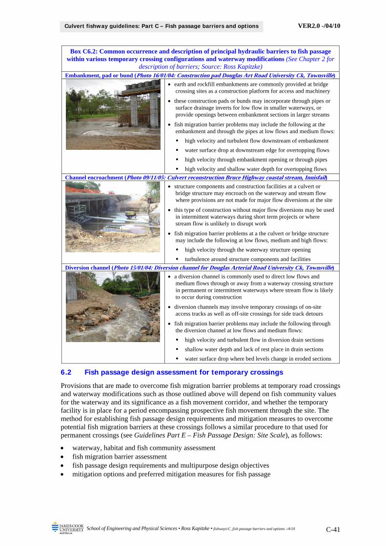
VER2.0 -/04/10
School of Engineering and Physical Sciences • Ross Kapitzke • fishways\C_fish passage barriers and options -/4/10 C-41
Culvert fishway guidelines: Part C – Fish passage barriers and options
Box C6.2: Common occurrence and description of principal hydraulic barriers to fish passage within various temporary crossing configurations and waterway modifications (See Chapter 2 for
description of barriers; Source: Ross Kapitzke) Embankment, pad or bund (Photo 16/01/04: Construction pad Douglas Art Road University Ck, Townsville)
earth and rockfill embankments are commonly provided at bridge crossing sites as a construction platform for access and machinery
these construction pads or bunds may incorporate through pipes or surface drainage inverts for low flow in smaller waterways, or provide openings between embankment sections in larger streams
fish migration barrier problems may include the following at the embankment and through the pipes at low flows and medium flows:
high velocity and turbulent flow downstream of embankment
water surface drop at downstream edge for overtopping flows
high velocity through embankment opening or through pipes
high velocity and shallow water depth for overtopping flows
Channel encroachment (Photo 09/11/05: Culvert reconstruction Bruce Highway coastal stream, Innisfail) structure components and construction facilities at a culvert or
bridge structure may encroach on the waterway and stream flow where provisions are not made for major flow diversions at the site
this type of construction without major flow diversions may be used in intermittent waterways during short term projects or where stream flow is unlikely to disrupt work
fish migration barrier problems at a the culvert or bridge structure may include the following at low flows, medium and high flows:
high velocity through the waterway structure opening
turbulence around structure components and facilities
Diversion channel (Photo 15/01/04: Diversion channel for Douglas Arterial Road University Ck, Townsville)
a diversion channel is commonly used to direct low flows and medium flows through or away from a waterway crossing structure in permanent or intermittent waterways where stream flow is likely to occur during construction
diversion channels may involve temporary crossings of on-site access tracks as well as off-site crossings for side track detours
fish migration barrier problems may include the following through the diversion channel at low flows and medium flows:
high velocity and turbulent flow in diversion drain sections
shallow water depth and lack of rest place in drain sections
water surface drop where bed levels change in eroded sections
6.2 Fish passage design assessment for temporary crossings
Provisions that are made to overcome fish migration barrier problems at temporary road crossings and waterway modifications such as those outlined above will depend on fish community values for the waterway and its significance as a fish movement corridor, and whether the temporary facility is in place for a period encompassing prospective fish movement through the site. The method for establishing fish passage design requirements and mitigation measures to overcome potential fish migration barriers at these crossings follows a similar procedure to that used for permanent crossings (see Guidelines Part E – Fish Passage Design: Site Scale), as follows:
waterway, habitat and fish community assessment fish migration barrier assessment fish passage design requirements and multipurpose design objectives mitigation options and preferred mitigation measures for fish passage

VER2.0 -/04/10
School of Engineering and Physical Sciences • Ross Kapitzke • fishways\C_fish passage barriers and options -/4/10 C-42
Culvert fishway guidelines: Part C – Fish passage barriers and options
6.2.1 Waterway, habitat and fish community assessment
Waterway, habitat and fish community assessment for the temporary crossing is focused on determining if the structure is located within a significant fish movement corridor, and if the fish community within the waterway is likely to be migrating through the site during the period that the temporary crossing is in place. Some information for the temporary road crossing will most likely be available from fish passage assessments undertaken for the permanent road crossing proposed for the site. Site assessment tasks undertaken as part of site scale planning and design for the permanent facility will provide the basis for much of the assessment for the temporary facility, including (see Guidelines Part E – Fish Passage Design: Site Scale):
catchment and waterway characterisation waterway and flow characteristics stream reach condition and fish habitat characteristics road-waterway crossings and fish migration barriers fish community and fish movement characteristics
An understanding of the waterway character in its catchment context (e.g. waterway type, channel form, geomorphology, permanence) and its flow characteristics (e.g. catchment hydrology, waterway hydraulics), provides the template for assessing fish habitat characteristics of the waterway. The condition of the stream reaches and the location, extent and nature of the fish habitat areas and other fish migration barriers with respect to the temporary crossing location in the waterway assist in defining the value of providing for fish passage at the crossing. Knowledge of the fish species diversity, abundance and distribution within the waterway, and an understanding of fish movement behaviour for these species provides the basis for fish passage design at the crossing to suit the requirements of the fish community for the stream.
6.2.2 Fish migration barrier assessment
Fish migration barrier assessment for the temporary road crossing determines the extent to which the crossing represents a potential fish migration barrier. Evaluation of barrier characteristics of the crossing is based on the configuration of the drainage structure, the hydraulic characteristics of the structure and adjoining stream reach, and the movement capabilities of the fish community attempting to pass through the site. The assessment follows a similar but slightly more rudimentary approach to that used as part of site scale planning and design for other waterway structures, including (see Guidelines Part E – Fish Passage Design: Site Scale):
configuration of temporary road crossing or waterway modification hydraulic conditions for waterway crossing and adjoining stream reach fish migration barrier evaluation for crossing
The configuration of the temporary crossing and the flow conditions at the crossing and in the adjoining stream reach determine the hydraulic characteristics and associated fish migration barrier effects of the crossing. Design flow conditions to be considered for fish passage would normally include low flow (flow up to approx 0.5 m deep – inundating channel bed for defined waterway), and medium flow (flow from approx 0.5 m to approx 1.5 m deep – below low flow channel bench for defined waterway). Depending on fish passage goals adopted for the site, the design condition for medium flow may not be relevant for temporary crossings (see below).
The temporary road crossing may represent a barrier to upstream fish passage if hydraulic conditions through the structure are more severe than swim capabilities, or do not otherwise suit behavioural characteristics of fish attempting to pass through. Consideration is given, not only to hydraulic conditions within the main part of the structure (e.g. culvert barrels), but also to conditions throughout the crossing and adjoining structures, to enable fish passage through all hydraulic zones from downstream to upstream at the structure. Principal fish migration barrier effects for road-waterway crossings are considered in terms of high velocity, reduced flow depth, lack of resting place, excess turbulence or water surface drop, as outlined in Guidelines Part E – Fish Passage Design: Site Scale, and as illustrated in Chapter 2 of this guideline. Common

VER2.0 -/04/10
School of Engineering and Physical Sciences • Ross Kapitzke • fishways\C_fish passage barriers and options -/4/10 C-43
Culvert fishway guidelines: Part C – Fish passage barriers and options
occurrence of the principal hydraulic barriers to fish passage within temporary crossing and waterway modifications are described and illustrated above in Section 6.1.
6.2.3 Fish passage design requirements and multipurpose design objectives
Fish passage goals and other multipurpose requirements for the temporary crossing or waterway modification are used to establish the configuration of fish passage facilities to overcome fish migration barrier problems at the site. The fish passage design requirements are identified in terms of overcoming particular hydraulic barriers within the structure for the design flow condition, and addressing critical drainage and other utility requirements (e.g. flow capacity, sediment, debris) for the site, including the following (see Section 4.1 of this guideline):
provide suitable hydraulic conditions (e.g. velocity, shelter, turbulence) through the structure to overcome adverse conditions (e.g. high velocities, shallow flow, lack of shelter, excess turbulence, water surface drop) to allow fish to pass upstream during low / medium flows
provide flow continuity through all zones of the structure and a continuous fish pathway and attraction flow to allow fish to readily locate the downstream entrance to the fish passage facilities and to move upstream through the crossing in response to flow
provide suitable shelter conditions at the structure inlet and in the upstream channel to allow fish that have passed through to exit the structure and move freely away into the stream during low / medium flows
minimise obstruction to flow, manage the effects of debris accumulation and sediment deposition, and provide for ready cleaning and maintenance in the waterway structure
maintain integrity of the temporary waterway crossing structure and provide for transport, drainage and other utility functions at the site
These specific design requirements form a subset of multipurpose requirements for the temporary road crossing relating to transport, drainage, fish passage and amenity (see Section 4.1). Design criteria for fish passage are established according to desired fish passage effectiveness of the crossing, fish passage design flows, and fish movement characteristics of the fish community, in a similar manner to that outlined for permanent structures (see Guidelines Part B – Fish Migration and Movement Behaviour and Guidelines Part E – Fish Passage Design: Site Scale).
In terms of fish passage effectiveness for temporary crossings, a slightly less conservative approach is likely to be applied compared with that used for a permanent crossing of the waterway. Of the three possible levels of fish passage effectiveness, the more restrictive approaches (Level 2 – Intermediate, and Level 3 - Restrictive) are suggested (Box C6.3).
Box C6.3: Suggested fish passage effectiveness levels and design criteria for provision of fish passage at temporary road crossings (See Guidelines Part B – Fish Migration and Movement Behaviour)
Fish passage effectiveness
Fish passage provisions for design flow conditions – upstream migration
Low flow (flow up to approx. 0.5 m deep)
Medium flow (from appr. 0.5 m to approx 1.5 m deep)
High flow (flow in excess of approx. 1.5 m deep)
Level 2 – intermediate
all native fish species, life stages and maturity
not mandatory for any native fish species
not mandatory for any native fish species
Level 3 – restrictive
all but outlier (1) native fish species (e.g. poor swimmers)
not mandatory for any native fish species
not mandatory for any native fish species
Notes 1 Restricted fish community may be identified on the basis of fish species diversity (e.g. icon species, weak swimming species), or on fish life stage and maturity (adult spawning / juvenile dispersal / adult dispersal / facultative movement for adults and juveniles)
This approach aims to provide passage for a reduced diversity of fish species, life stage and maturity, and / or a reduced range of flow conditions relative to that otherwise achieved through 100% effectiveness in passage for the complete native fish community over the full range of fish migration flows in the waterway. The fish passage effectiveness band for the temporary crossing,

VER2.0 -/04/10
School of Engineering and Physical Sciences • Ross Kapitzke • fishways\C_fish passage barriers and options -/4/10 C-44
Culvert fishway guidelines: Part C – Fish passage barriers and options
and associated fish passage design flows and swim speeds for the target fish community, are chosen by the designer on a discretionary basis, taking into account the following:
fish passage effectiveness band for associated permanent crossing of waterway fish movement corridor classification aquatic fauna connectivity / fish passage goals (high – low) for the waterway fish migration barrier hydraulic conditions for temporary crossing feasibility of overcoming the fish migration barrier at the crossing
6.3 Mitigation measures for fish passage at temporary crossings
A range of mitigation measures can be used at temporary road crossings and waterway modifications to overcome fish migration barrier problems and to address fish passage goals and other multipurpose requirements for the site. This includes fishway devices similar to those used for permanent crossings (see Chapter 4) and various other measures to suit the short term nature of the installation. The type and configuration of these mitigation measures is established on the basis of fish migration barrier characteristics and design requirements within the various hydraulic zones of the structure, as outlined above. Provisions that are made for fish passage at the temporary crossings may include one or more of the following types of measures:
enhancement of standard drainage facilities (e.g. increased flow area in pipe culverts) alternatives to standard drainage facilities (e.g. temporary bridge in lieu of culverts) variations to standard drainage facilities (e.g. rock ramp grade control in lieu of rock chute) specialist devices incorporated into standard drainage facilities (e.g. baffles in pipe culverts)
Fish passage provisions for the temporary crossing may include treatment measures for the waterway structure (e.g. increased culvert flow area) and measures in the adjoining stream channel (e.g. rock ramp) that work together to meet fish passage and other requirements for the site. More rudimentary fabrication and construction options may be considered for temporary fish passage provisions than those used in a permanent facility to suit the short term nature of the installation (e.g. temporary fixing of devices to culverts).
The key principles and design considerations for mitigation measures to meet fish passage requirements for temporary road-waterway crossings are outlined in Box C6.4. These provisions complement principles and configuration options for fish passage requirements at permanent crossings outlined in Chapter 4. Whereas this information guides the general design and application of fish passage measures for various types of temporary road crossings and waterway modifications at a site, actual design provisions and configuration requirements for the facility should be established on the basis of the site characteristics and through reference to specific design characteristics for particular fishway component types outlined in these guidelines.
Illustrations of particular fish migration barrier situations and mitigation measures applied for temporary road crossings are given below for the University Creek Douglas Arterial Road and Bruce Highway Corduroy Creek case study projects.
Box C6.4: Key principles and design considerations for mitigation measures to meet fish passage requirements for temporary road-waterway crossings (see also Box C4.2 for permanent crossings)
Design aspect / parameter Design consideration, comment and rationale
Construction timing and general provisions for fish passage
Avoid seasonal flow conditions
where provisions for fish passage are to be made at a road-waterway crossing, it is desirable to construct all stream works in the dry season and to not rely on temporary creek crossings during wet season and other major flow periods
desirable to provide for removal or upgrade of the temporary crossing if road construction extends during wet season and other major flow periods
Establish temporary facilities prior to seasonal flows
ensure that provisions for fish passage at temporary crossings are in place prior to seasonal stream flow events as it is difficult to remediate the drainage structures to provide for fish passage once the stream is flowing strongly
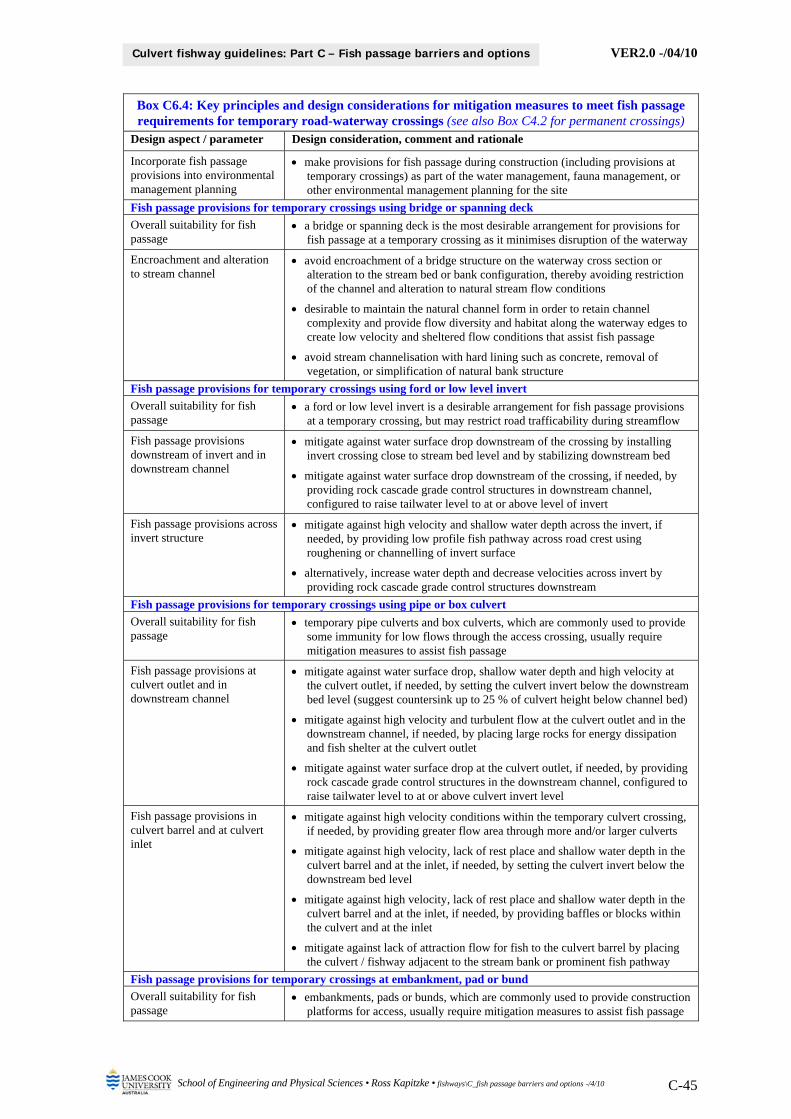
VER2.0 -/04/10
School of Engineering and Physical Sciences • Ross Kapitzke • fishways\C_fish passage barriers and options -/4/10 C-45
Culvert fishway guidelines: Part C – Fish passage barriers and options
Box C6.4: Key principles and design considerations for mitigation measures to meet fish passage requirements for temporary road-waterway crossings (see also Box C4.2 for permanent crossings)
Design aspect / parameter Design consideration, comment and rationale
Incorporate fish passage provisions into environmental management planning
make provisions for fish passage during construction (including provisions at temporary crossings) as part of the water management, fauna management, or other environmental management planning for the site
Fish passage provisions for temporary crossings using bridge or spanning deck
Overall suitability for fish passage
a bridge or spanning deck is the most desirable arrangement for provisions for fish passage at a temporary crossing as it minimises disruption of the waterway
Encroachment and alteration to stream channel
avoid encroachment of a bridge structure on the waterway cross section or alteration to the stream bed or bank configuration, thereby avoiding restriction of the channel and alteration to natural stream flow conditions
desirable to maintain the natural channel form in order to retain channel complexity and provide flow diversity and habitat along the waterway edges to create low velocity and sheltered flow conditions that assist fish passage
avoid stream channelisation with hard lining such as concrete, removal of vegetation, or simplification of natural bank structure
Fish passage provisions for temporary crossings using ford or low level invert
Overall suitability for fish passage
a ford or low level invert is a desirable arrangement for fish passage provisions at a temporary crossing, but may restrict road trafficability during streamflow
Fish passage provisions downstream of invert and in downstream channel
mitigate against water surface drop downstream of the crossing by installing invert crossing close to stream bed level and by stabilizing downstream bed
mitigate against water surface drop downstream of the crossing, if needed, by providing rock cascade grade control structures in downstream channel, configured to raise tailwater level to at or above level of invert
Fish passage provisions across invert structure
mitigate against high velocity and shallow water depth across the invert, if needed, by providing low profile fish pathway across road crest using roughening or channelling of invert surface
alternatively, increase water depth and decrease velocities across invert by providing rock cascade grade control structures downstream
Fish passage provisions for temporary crossings using pipe or box culvert
Overall suitability for fish passage
temporary pipe culverts and box culverts, which are commonly used to provide some immunity for low flows through the access crossing, usually require mitigation measures to assist fish passage
Fish passage provisions at culvert outlet and in downstream channel
mitigate against water surface drop, shallow water depth and high velocity at the culvert outlet, if needed, by setting the culvert invert below the downstream bed level (suggest countersink up to 25 % of culvert height below channel bed)
mitigate against high velocity and turbulent flow at the culvert outlet and in the downstream channel, if needed, by placing large rocks for energy dissipation and fish shelter at the culvert outlet
mitigate against water surface drop at the culvert outlet, if needed, by providing rock cascade grade control structures in the downstream channel, configured to raise tailwater level to at or above culvert invert level
Fish passage provisions in culvert barrel and at culvert inlet
mitigate against high velocity conditions within the temporary culvert crossing, if needed, by providing greater flow area through more and/or larger culverts
mitigate against high velocity, lack of rest place and shallow water depth in the culvert barrel and at the inlet, if needed, by setting the culvert invert below the downstream bed level
mitigate against high velocity, lack of rest place and shallow water depth in the culvert barrel and at the inlet, if needed, by providing baffles or blocks within the culvert and at the inlet
mitigate against lack of attraction flow for fish to the culvert barrel by placing the culvert / fishway adjacent to the stream bank or prominent fish pathway
Fish passage provisions for temporary crossings at embankment, pad or bund
Overall suitability for fish passage
embankments, pads or bunds, which are commonly used to provide construction platforms for access, usually require mitigation measures to assist fish passage

VER2.0 -/04/10
School of Engineering and Physical Sciences • Ross Kapitzke • fishways\C_fish passage barriers and options -/4/10 C-46
Culvert fishway guidelines: Part C – Fish passage barriers and options
Box C6.4: Key principles and design considerations for mitigation measures to meet fish passage requirements for temporary road-waterway crossings (see also Box C4.2 for permanent crossings)
Design aspect / parameter Design consideration, comment and rationale
Fish passage provisions downstream of embankment and culvert and in downstream channel
mitigate against water surface drop, shallow water depth and high velocity at the culvert outlet, if needed, by setting the culvert invert below the downstream bed level (suggest countersink up to 25 % of culvert height below channel bed)
mitigate against high velocity and turbulent flow at the culvert outlet and in the downstream channel, if needed, by placing large rocks for energy dissipation and fish shelter at the culvert outlet
mitigate against water surface drop at the culvert outlet, if needed, by providing rock cascade grade control structures in the downstream channel, configured to raise tailwater level to at or above culvert invert level
Fish passage provisions through opening in embankment or bund
mitigate against high velocity conditions through the embankment opening, if needed, by providing greater flow area through a wider opening
mitigate against high velocity and lack of rest place through the embankment opening, if needed, by providing a roughly formed rock surface with channel complexity and flow diversity along the edges of the opening
Fish passage provisions through pipe or box culvert under embankment
mitigate against high velocity conditions within the temporary culvert, if needed, by providing greater flow area through more and/or larger culverts
mitigate against high velocity conditions within the temporary culvert, if needed, by setting the culvert invert below the downstream bed level
mitigate against lack of attraction flow for fish to the temporary culvert by placing the culvert adjacent to the stream bank or prominent fish pathway
Fish passage provisions across embankment or bund
mitigate against high velocity and shallow water depth across the embankment or bund, if needed, by providing a rock lined invert section across the embankment to concentrate flows during overtopping
mitigate against high velocity and shallow water depth across the embankment or bund, if needed, by providing a discontinuous rock sill on the downstream edge of the bund wall, with flow openings at the sill to attract fish
provide rock chute connections from the downstream channel to areas of flow concentration at invert sections or sill openings (preferably adjacent to stream bank) on construction pad for overtopping flows
Provisions for breaching embankment or bund
although not desirable, consider using an erodible (fuse plug) section through the construction pad that would breach in high flows
allow for monitoring and response to overtopping flood flows on embankment, including contingency plans to rapidly remove the embankment or breach it by excavation if needed to expedite the failure and for clearance of the obstruction
Fish passage provisions for temporary crossings at diversion drain
Overall suitability for fish passage
diversion drains are commonly used at temporary crossings and usually require mitigation measures to assist fish passage
Channel form for diversion drain
mitigate against high velocity and lack of rest place in diversion drain by providing channel complexity and flow diversity along the waterway edges
avoid stream channelisation with hard lining such as concrete, removal of vegetation, or simplification of natural bank structure
ensure that the channel configuration and rock protection in the waterway provides for stability and control of bed erosion, which may otherwise progress further upstream and form a drop in the bed that represents a fish migration barrier
Fish passage provisions in diversion channel or drain
mitigate against high velocity, shallow water depth and lack of rest place in the diversion drain by adopting low gradient drain sections and incorporating large randomly placed rocks in the drain bed and banks to ensure hydraulic diversity
mitigate against high velocity, shallow water depth and water surface drop in the diversion drain, if needed, by providing rock cascade grade control structures with overall longitudinal gradient of from 1 in 20 and 1 in 10 between cascades
construct cascade structures as random rock bars placed at about 2 m centres longitudinally in the drain, with a drop of between 100 mm and 200 mm between adjoining rock bar cascade structures

VER2.0 -/04/10
School of Engineering and Physical Sciences • Ross Kapitzke • fishways\C_fish passage barriers and options -/4/10 C-47
Culvert fishway guidelines: Part C – Fish passage barriers and options
6.4 Temporary road crossing – University Creek Douglas Arterial project
The Douglas Arterial Road project in Townsville provides an example of fish passage provisions for temporary crossings, where a construction access track, working platform, rock invert, pipe culvert and diversion drain were used as part of temporary crossing and construction facilities for the new bridge crossing of University Creek. Fish migration barrier problems were experienced as a result of the temporary crossing, construction pad and other structures, and several mitigation measures were attempted to provide for fish passage during the various stages of construction. The following material, which is taken from Kapitzke (2006c) outlines the fish migration barrier problems and the various mitigation measures attempted during the project.
6.4.1 Temporary crossing facilities used during construction
The Douglas Arterial (Ring Road) Project in Townsville includes a 4-span bridge crossing of University Creek and an associated 80 m long stream channel diversion that incorporates 2 rock ramp grade control structures (see Guidelines Part H1 – Douglas Arterial Road Prototype Rock Ramp Fishway). The bridge crossing, diversion drain and rock ramp structures were constructed over an 18 month period during 2003 and 2004. The main temporary crossing arrangements used for construction of the bridge were intended to be removed prior to the end of 2003, but as a result of construction delays, were left in place during the 2003/04 wet season and subsequent flow periods. Fish migration in University Creek was affected by hydraulic barriers at the various temporary crossing structures placed in the creek, which obstructed clear passage of fish to spawning and growth habitat areas and to the Discovery Drive prototype fishway upstream (see Guidelines Part F1 – Discovery Drive Prototype Offset Baffle Fishway).
A temporary crossing was first installed late in 2003 to provide a working platform for cranes to raise the bridge girders onto the bridge superstructure. This involved an earth pad approximately 30 m wide across the creek, with a single barrel 900 mm diameter corrugated pipe through the embankment that was intended to provide a low capacity stream flow diversion through the existing creek channel. The pipe capacity was far from adequate to take any substantial flow in University Creek, and the earth pad embankment, although readily overtopped with fast flowing water, was sufficiently wide and robust to withstand overtopping without breaching. The pipe exited into a stream channel section reinforced with random boulder-size rock protection. This crossing was severely overtopped during flow in University Creek in January 2004 (see below).
The construction pad and pipe culvert were removed on completion of the bridge girder installation in January 2004, and a rock invert crossing was installed. Construction logistics however, soon required installation of another low level pipe and embankment crossing to provide for earthworks haulage across the creek at the site. Although the new structure was itself in place for only a few weeks and presented a lesser obstacle than the previous pipe installation, it still represented a barrier during a flow event in February 2004 (see below). This series of temporary crossings, from the rock invert to the low level pipe, was eventually superceded by a temporary rock lined diversion drain, which was in place through to development of the permanent diversion drain and rock ramp grade control structures in October 2004.
6.4.2 Fish migration barrier problems associated with temporary facilities
University Creek has a community of up to 13 native freshwater fish species, which migrate upstream during seasonal flow conditions for spawning or growth dispersal (Kapitzke 2006c). This includes two species of catfish (Black catfish Neosilurus ater and Hyrtl’s tandan Neosilurus hyrtlii), and several other native species (including Eastern rainbowfish Melanotaenia splendida, Fly-specked hardyhead Craterocephalus stercusmuscarum, Purple-spotted gudgeon Mogurnda adspersa, and Agassiz’s glass perch Ambassis agassizii). The temporary crossing structures at the Douglas Arterial Project site affected upstream migration to valuable habitat areas and also impeded fish movement to the Discovery Drive prototype fishway facility, where hydraulic and biological monitoring and evaluation was underway during the 2003/04 wet season.

VER2.0 -/04/10
School of Engineering and Physical Sciences • Ross Kapitzke • fishways\C_fish passage barriers and options -/4/10 C-48
Culvert fishway guidelines: Part C – Fish passage barriers and options
The earth pad and single barrel 900 mm pipe substantially impacted flow conditions at the site and represented major barriers to upstream fish movement during a series of storms and flow events in University Creek from 12-16 January 2004 (Box C6.5). High velocity flow in the pipe created very turbulent conditions at the outlet where the jet impacted on the rip rap downstream. Stream flow surcharged the pipe and embankment daily during this period, with the downstream face of the embankment forming a waterfall and retreating over 10 m in headward erosion by 16 January, when the maximum flow event occurred.
The Plotosid Catfish and a number of other species attempting to move upstream past the crossing site, were clearly evident at the pipe outlet during this series of flow events. Many observations were made of fish attempting to pass through the pipe being washed back and thrown against the rock. Some fish were able to pass through at lower flow stages, aided by the build up of tailwater due to the rock boulder pools at the pipe outlet. With water overtopping the road embankment by approximately 100 mm on 15 January 2004, velocities at the pipe outlet jet were measured in the range 2.2 m/s just inside the pipe edge, to 2.9 m/s near the pipe centre.
Box C6.5: Fish passage and erosion problems associated with flooding at temporary construction pad and pipe access crossing for Douglas Arterial Road project crossing
of University Creek – January 2004 (Source: Ross Kapitzke)
Pipe outlet and downstream diversion drain – looking downstream (14/01/04)
Turbulent high velocity flow downstream of pipe – looking upstream (15/01/04)
Flow overtopping construction pad – looking upstream (16/01/04)
Erosion and turbulent high velocity flow at outlet – looking downstream (17/01/04)
On removal of the embankment pad and low flow pipe in late January 2004, the rock invert crossing was installed for a short period for light vehicle access (Box C6.6). This crossing, which comprised a rock lined drain, a gravel causeway and a steeper cascade section downstream, was not subjected to flow and therefore not tested for effectiveness. Whilst this was a genuine attempt by the contractor to provide for the flood and erosion functions of the waterway while not inhibiting fish passage, several aspects of the structure represented potential fish migration barrier problems. For example, the cascade section downstream of the causeway incorporated a series of pools and drops, but nevertheless appeared to be too steep and to contain insufficient large rock on the bed and banks to provide shelter for fish.

VER2.0 -/04/10
School of Engineering and Physical Sciences • Ross Kapitzke • fishways\C_fish passage barriers and options -/4/10 C-49
Culvert fishway guidelines: Part C – Fish passage barriers and options
The low level pipe crossing was subsequently installed in February 2004 so that the regular truck movements would not create water disturbance in the shallow flow environment that occurred in University Creek during the spoil haulage operation (Box C6.6). The expectation of the contractor with respect to fish passage was that because the pipe and causeway embankment were contained within the channel, the fish would pass through the pipe at low flows and pass over the embankment fill at higher flows. It was inevitable however, that the pipe crossing would restrict fish passage upstream (at least for part of the time) during any substantial creek flows.
This obstruction occurred in February 2004 when fish were for a time unable to pass through the full-flowing pipe due to the high velocities and lack of shelter and resting areas downstream. During the February flow event, the temporary pipe installation was monitored for velocities at the pipe inlet and outlet. Velocities ranged from 1.6 m/s – 2 m/s at the outlet, and from 1 m/s – 1.4 m/s at the pipe inlet on 12 February 2004, but conditions varied substantially on a daily basis as the stream rose and fell in response to rainfall. Whilst fish were unable to pass through the full-flowing pipe, some fish were apparently able to negotiate their way upstream through the pipe at various other stages of this flow event. The pipe length was considerably less in this installation than in the January installation under the wide road embankment, and although conditions were slightly more favourable for fish passage, the pipe was still clearly too small.
Whilst all flow events during 2003/04 were relatively minor, fish migration to upstream habitat areas and to the Discovery Drive fishway was affected by the temporary road crossings at the Douglas Arterial Road crossing site during the largest events in January and February 2004. Although some fish were able to negotiate the temporary crossings, they were delayed in their upstream movement (possibly for periods of 6 hours or more), thus affecting passage at the Discovery Drive crossing as the hydrograph peak had passed long before they reached this site. The number of fish reaching the upstream fishway site and their motivation to move further upstream or to spawn are expected to have been reduced as a result. Furthermore, those fish that were able to pass through the downstream obstructions may have lost their full capacity to spawn due to the delay and the exertion in overcoming the barrier.
Box C6.6: Fish passage problems associated with flooding at temporary rock invert and pipe access crossing for Douglas Arterial Road project crossing of University
Creek – February 2004 (Source: David Derrick)
Rock invert crossing in very low flow conditions – looking upstream (02/02/04)
Low flow pipe crossing in very low flow conditions – looking upstream (10/02/04)
6.4.3 Suggested mitigation measures to improve fish passage
Of the series of temporary road crossing configurations installed at the Douglas Arterial Road crossing of University Creek, virtually all drainage structure components represented a barrier to upstream fish migration as a result of some poorly conceived aspect that did not adequately take account of the adverse hydraulic conditions associated with temporary crossing facilities or the swim behaviour of the fish attempting to pass. The initial construction pad and small diameter pipe were intended for dry weather conditions in the creek and were inappropriate for the flood flows experienced as a result of extending the construction phase through the wet season period.

VER2.0 -/04/10
School of Engineering and Physical Sciences • Ross Kapitzke • fishways\C_fish passage barriers and options -/4/10 C-50
Culvert fishway guidelines: Part C – Fish passage barriers and options
The other measures subsequently installed after removal of the construction pad and low flow pipe each represented genuine attempts by the contractor to provide for fish passage through the site during construction of the road. These endeavours were, however, mainly reactive to situations rather than being proactive, and the overall result was unsatisfactory.
The project demonstrates the importance of avoiding the wet season period for major temporary waterway crossings and making appropriate provisions for fish passage where these temporary crossings are required. Potential mitigation measures that could have been applied for the various stages of the temporary crossing facilities that were installed are outlined below.
Potential mitigation measures for the various stages of the temporary road crossing at the Douglas Arterial Road crossing of University Creek
Construction pad and low flow pipe culvert
provide greater flow area in the temporary low flow pipe by using more and/or larger pipe culverts set the invert level of the pipe culvert below the bed level of the downstream drainage channel provide rock cascade structures in the diversion drain downstream of the pipe provide a rock lined invert section across the construction pad to concentrate flows during overtopping provide rock chute connections from the downstream channel to invert section on construction pad for
overtopping flows provide an erodible section through the construction pad that would breach in high flows
Rock invert crossing and diversion drain
embed rows of large rock laterally across the channel as rock cascade structures to produce an overall longitudinal gradient of from 1 in 20 and 1 in 10 between cascade structures
cascade structures to comprise random rock bars placed at about 2 m centres longitudinally in the drain nominal crest of the most upstream bar to be 200 mm or so above the invert crest provide a drop of between 100 mm and 200 mm between adjoining rock bar cascade structures
Low embankment and low flow pipe
provide greater flow area in the temporary low flow pipe by using more and/or larger pipe culverts set the invert level of the pipe culvert below the bed level of the downstream drainage channel provide fish shelter areas and rock cascades in the channel at the pipe outlet provide rock chute connections from the downstream channel up and over the low embankment for
overtopping flows
Rock lined diversion drain
embed rows of large rock laterally across the channel as rock cascade structures to produce an overall longitudinal gradient of from 1 in 20 and 1 in 10 between cascade structures
cascade structures to comprise random rock bars placed at about 2 m centres longitudinally in the drain provide a drop of between 100 mm and 200 mm between adjoining rock bar cascade structures
6.5 Temporary road crossing – Bruce Highway Corduroy Creek project
The Bruce Highway Corduroy Creek to Tully project provides an example of fish passage provisions for temporary crossings, where a bund wall was used as a platform for construction of the new bridge over the Tully River. An assessment was undertaken of potential barriers to fish migration associated with development of the bund wall across part of the river, and mitigation options were proposed to provide for fish passage connectivity through the site during the construction phase. The actual bund wall configuration adopted for construction provided a larger river opening and less flow constriction than would have applied for the initially proposed bund configuration, and mitigation measures considered for the initial bund design were therefore not required. The following material, which is taken from Kapitzke (2007a) outlines the fish migration barrier problems and mitigation options identified for the initial proposal.
6.5.1 Characteristics of bund for Tully River bridge construction
Construction of the new bridge over the Tully River involved placement of rock protected sand bunds on the northern and southern banks of the river. Tully River is a perennial stream subject to extensive flood effects. The restriction in flow area for flow conditions up to the level of the

VER2.0 -/04/10
School of Engineering and Physical Sciences • Ross Kapitzke • fishways\C_fish passage barriers and options -/4/10 C-51
Culvert fishway guidelines: Part C – Fish passage barriers and options
top of the bunds and the associated increased velocities in the river had the potential to adversely affect upstream fish passage through the site during the construction period (from mid 2007).
The characteristics of the initial bund crossing configuration were as follows:
sand bunds constructed on the northern and southern banks of the Tully River geofabric and rock protection provided on the bund sides and ends bunds 22 m wide and about 3 m high above the bed of the Tully River gap of 20m provided between the bunds for Tully River flow (initial width – later widened) bunds were expected to be in place for approximately 6 months from June – December 2007 normal Tully River discharge expected to be about 100 m3/s during the construction period Tully River typical flow depth of 2 m at velocity of about 0.5 m/s at bridge site without bund Tully River velocity through bund opening of about 2.5 m/s during construction (based on
initial width – later widened with reduced velocity) 6.5.2 Fish movement characteristics for construction period
The Tully Murray floodplain waterways have a fish community of up to 56 native freshwater species (Kapitzke 2006a), and consideration has been given to the number of species that would likely be migrating upstream through the bridge crossing site on the Tully River during the construction period. The question of how critical upstream migration through the bridge site is to the life cycle of these species, and for the overall condition of the fish community, was considered in terms of the following species:
species displaying obligatory upstream movement during construction June – December species for which upstream movement is not obligatory during construction period species displaying obligatory upstream movement post-construction January – June
Information on expected upstream migration as adults or as juveniles during these seasonal periods was examined in terms of fish movement behaviour for the various fish life cycle groups (catadromous, potamodromous, amphidromous). Several catadromous (e.g. Long finned eel Anguilla reinhardti; Barramundi Lates calcarifer) and potamodromous (e.g. Sooty grunter Hephaestus fuliginosus; Fly specked hardyhead Craterocephalus stercusmuscarum) species clearly have obligatory upstream migration behaviour patterns during the June – December period. Large winter and spring flow conditions within the construction period may also trigger upstream migration of species, which respond to flood flows. Furthermore, upstream migration as adults (spawning) or juveniles (growth) is obligatory during the post construction period of January – June for many catadromous and potamodromous species (e.g. Jungle perch Kuhlia rupestris; Empire gudgeon Hypseleotris compressa; Black catfish Neosilurus ater).
Because of the abundance and diversity of the Tully River fish community and the limited specific information on the fish movement characteristics of particular species, a conservative approach was taken in establishing fish passage goals for this temporary crossing facility. Provisions for upstream migration were made over the full range of flow conditions and timings for all fish in the Tully River. This provided for upstream migration at the crossing during the construction period June – December, and during the scheduled post construction period January – June, in case construction was delayed and the bund walls were still in place.
6.5.3 Hydraulic conditions and fish migration barriers at waterway opening
Potential fish migration barrier effects for the temporary crossing were evaluated in terms of the estimated hydraulic conditions associated with the bund wall facility. For the initial configuration of the bund wall (20 m opening), normal seasonal flows in the Tully River during the construction period June – December would increase the estimated average velocities through the opening from 0.5 m/s to 2.5 m/s due to the restricted flow area. Velocities adjacent to the rock protection on the end of the bund walls were expected to be in the range 1.5 m/s to 2.5 m/s due to the roughness of the rock work.

VER2.0 -/04/10
School of Engineering and Physical Sciences • Ross Kapitzke • fishways\C_fish passage barriers and options -/4/10 C-52
Culvert fishway guidelines: Part C – Fish passage barriers and options
It was considered unlikely that fish attempting to migrate upstream in the Tully River would be able to negotiate their way through the bund wall opening under these conditions. The most favourable swim path on the edges of the opening adjacent to the rock protection works on the bund wall ends would produce more severe flow conditions than the Tully River fish community could readily negotiate. The requirement to pass 22 m or more along the extent of the bund wall opening against velocities of greater than 1.5 m/s is beyond the burst or prolonged speed capacity of any of these fish species, either for juveniles or adults. Flow and shelter conditions are also likely to be too adverse for fish to pass through using a burst and rest swim pattern.
For larger flows in the Tully River that might occur during the construction period, velocities through the bund wall opening were expected to increase above the anticipated 1.5 m/s to 2.5 m/s range, and the bund wall was expected to overtop when flow depth exceeded the bund wall height of about 3 m. During shallow overtopping conditions of less than 0.5 m depth, flow on the downstream edge of the bund wall was likely to be too severe for upstream fish passage over the bund wall, and flow conditions on top of the bund would likely be too severe for fish passage across the bund itself. For higher flows where the bund wall was drowned out, fish passage across the bund wall was unlikely to be restricted, particularly adjacent to the river banks where the fish were likely to be moving.
The initial configuration proposed for the bund walls (20 m opening width) was therefore considered likely to present a migration barrier to fish attempting to pass upstream in the Tully River under the following flow conditions:
normal seasonal flow of 2 m depth passing through the bund wall opening increased river flow of up to 3 m depth passing through the bund wall opening flood flow overtopping the bund walls to a depth of up to 0.5 m
These fish migration barriers would apply during the construction period June – December when many fish species would be attempting to migrate upstream. The barriers would be more significant for delayed construction of the bridge, with bund walls still in place during the period January – June when a large number of fish species would be attempting to migrate upstream.
6.5.4 Mitigation measures to provide for fish migration
A number of mitigation measures were proposed to address potential fish migration barriers associated with the initial bund wall configuration (20 m opening), although these measures were not adopted for the larger opening width actually used for construction. Two treatment measures were proposed (Box C6.7) to mitigate the effects of adverse hydraulic conditions across the range of flows, and a third measure was suggested, subject to monitoring of performance during operation of the bund walls over the construction period for the bridge.

VER2.0 -/04/10
School of Engineering and Physical Sciences • Ross Kapitzke • fishways\C_fish passage barriers and options -/4/10 C-53
Culvert fishway guidelines: Part C – Fish passage barriers and options
Box C6.7: Provisions for fish passage in Tully River temporary crossing (20 m wide river opening)
Plan - Bridge and Temporary Bund Mitigation Measure 1: Rock Bench
Elevation - Bridge and Temporary Bund Mitigation Measure 2: Rock Sill
Mitigation Measure 1 – Rock Bench at End of Bund Walls
This treatment measure involved placement of a rock bench 2 m wide and approximately 1.5 m high on the river bed at the end of each of the bund walls adjacent to the river opening through the bunds. The benches would be constructed from large rock rip rap and would be submerged during normal flow conditions corresponding to typical flow depths of about 2 m through the bund wall opening. The top of the bench would be roughly formed with coarse rock, with a nominal level for the top of bench of about 0.5 m below the normal Tully River flow level through the opening. The benches on the end of each of the bunds would extend through the opening and 5 m around the sides of the bunds upstream and downstream of the opening.
The purpose of the rock benches was to reduce the depth of flow adjacent to the ends of the bund walls, where the fish were most likely to be attempting to pass upstream through the opening. With the benches of coarse rock rip rap submerged a nominal 0.5 m below the normal flow level, shallow flow of less than 0.5 m depth across the diverse substrate provided on these benches was likely to provide suitable conditions for fish to negotiate their way along the ends of the bund walls on either side of the opening.
For higher river discharges and deeper flow through the opening up to the point of overtopping of the bund walls, the rock benches placed at nominal 1.5 m above the river bed may still provide suitable flow conditions for fish to pass along the ends of the bund walls. Monitoring of performance when the bund walls were in place during the construction period may have indicated the need to raise the rock bench level adjacent to the bund walls (Mitigation Measure 3 – see below), or to supplement the rock placement on the rock benches to provide improved flow conditions for fish movement (e.g. rock ramp type configuration with ridges and slots).
Mitigation Measure 2 – Rock Sill on Downstream Edge of Bund Walls
This treatment measure involved placement of a rock sill on the downstream edge of the bund walls. The rock sill would be constructed from large rock rip rap that was finished approximately 0.5 m above the top of the bund walls, and connected with the rock protection works on the downstream face of the bund walls. The rock sill would be discontinuous along the length of each
Flow
Tully River
Bruce Highway to Cardwell
Sand bund with low flow opening
Mitigation Measure 2: Rock Sill with openings
Mitigation Measure 1: Rock Bench
Tully River looking upstream
Mitigation Measure 1: Rock Bench – see detail
Sand bund with rock protected sides & ends – approx 3 m high
21 m
Q10 flood
Mitigation Measure 2: Rock Sill – see detail
Distorted scale: Approx
7-span, 2-lane bridge
0.5 m
Rock bench - Coarse rock riprap
Sand bund with rock protected
2 m
1.5 m
Nominal crest
Low flow Mitigation Measure 3:
0.5 m
Rock sill – large riprap placed with approx 10 m openings between piers and at banks
Sand bund with rock protected
Nominal crest
Overtopping flow
Flow

VER2.0 -/04/10
School of Engineering and Physical Sciences • Ross Kapitzke • fishways\C_fish passage barriers and options -/4/10 C-54
Culvert fishway guidelines: Part C – Fish passage barriers and options
bund wall, with segments of about 25 m length placed downstream of each of the bridge pier locations, leaving intermediate gaps of about 25 m without the rock sill. Gaps would be provided in the rock sills at the ends of the bund walls adjacent to the river banks on either side.
The purpose of the rock sills was to increase flow depth on top of the bund walls at the time of overtopping of the bund walls, and to provide localised flow-through sections along the downstream edge of the bund walls to which fish will be attracted in their upstream movement onto and beyond the bund wall. The gaps in the rock sills at the river bank ends of the bund walls are particularly important as this is the preferred movement path for fish along the edge of the stream during flood flow conditions. For higher river discharge and greater submergence of the bund walls, the bund walls would tend to be drowned out, with reduced fish migration barrier effect on the downstream edge and over the bund wall. The rock sill treatment will assist with fish passage up to the point of drown out of the bunds (minimal afflux), beyond which there should be no further obstruction to fish passage.
Mitigation Measure 3 – Higher Level Rock Bench at End of Bund Walls (provisional)
This was a provisional treatment measure that involved a second stage higher level rock bench on the end of the bund walls if required to overcome fish migration barrier effects during higher than normal Tully River flow through the opening between the bund walls. The higher level bench would be constructed from large rock rip rap, placed about 1 m wide and finished to a level of about 2.5 m above the river bed, so that these benches were submerged during high flow conditions passing through the bund wall opening. As for the lower level bench, the top of the bench would be roughly formed with coarse rock, with a nominal level for the top of bench to be adopted on site according to dominant flow conditions in the Tully River.
The purpose of the second stage higher level rock benches was to reduce the flow depth adjacent to the bund wall ends to provide more favourable hydraulic conditions for fish to pass upstream through the opening. With these higher level benches of coarse rock rip rap submerged, shallow flow of less than 0.5 m depth across the diverse substrate on these benches was likely to provide suitable conditions for fish to negotiate their way along the ends of the bund walls on either side of the opening during higher Tully River flows. This provisional measure would be applied and modified if necessary, subject to monitoring performance of the first stage rock benches under the prevailing flow conditions applying during the construction period for the bridge crossing.

VER2.0 -/04/10
School of Engineering and Physical Sciences • Ross Kapitzke • fishways\C_fish passage barriers and options -/4/10 C-55
Culvert fishway guidelines: Part C – Fish passage barriers and options
7 BIBLIOGRAPHY Bates, K., Barnard, R., Heiner, B., Klavas, J.P., and Powers, P.D., 2003, Design of road culverts for fish
passage, Washington Department of Fish and Wildlife. Boubee, J. Jowett, I., Nichols, S. Williams, E. 1999, Fish passage at culverts, a Review with possible
solutions for New Zealand indigenous species, Report prepared for NIWA, Department of Conservation, Wellington, New Zealand.
Cotterell, E. 1998, Fish passage in streams, Fisheries guidelines for design of stream crossings, Fish Habitat Guideline FHG 001, DPI Fisheries Group.
Dane, B. G. 1978, Culvert guidelines: Recommendations for the design and installation of culverts in British Columbia, Fisheries and Marine Service, Dept of Fisheries and Environment, Vancouver, BC.
Ead, S.A., Rajaratnam, N. and Katopodis, C. 2002, “A generalized study of the hydraulics of culvert fishways”, Journal of Hydraulic Engineering, ASCE.
Engel, P. 1974, Fish facilities for culverts of the McKenzie Highway, National Water Research Institute, Burlington Ontario 33p.
Fairfull, S. and Witheridge, G. 2003, Why do fish need to cross the road? Fish passage requirements for waterway crossings, NSW Fisheries, Cronulla NSW.
Kapitzke, I.R. 2003, Travelling fellowship report: Trips to Europe and North America, January 2001 and June 2002, Land and Water Australia Project JCU 15, Land and Water Australia and James Cook University, Available at: http://www.rivers.gov.au/research/rlrd/streamrehab.htm.
Kapitzke, I.R. 2006a, Bruce Highway Corduroy Creek to Tully planning study Provisions for fish passage – Road corridor scale Assessment Task 1A, report to Maunsell Australia and Department of Main Roads.
Kapitzke, I.R. 2006b, Discovery Drive offset baffle fishway for box culverts (Prototype Fishway # 1): Case study project design and prototype monitoring report to April 2005, report to Dept of Main Roads.
Kapitzke, I.R. 2006c, Douglas Arterial Project rock ramp fishway for open channels (Prototype Fishway # 2): Case study project design and prototype monitoring report to April 2005, report to Dept Main Roads.
Kapitzke, I.R. 2007a, Bruce Highway Corduroy Creek to Tully High School Provisions for fish passage – Preliminary Design Assessment Tasks 1B and 2, report to Maunsell Australia and Dept of Main Roads.
Kapitzke, I.R. 2007b, Discovery Drive corner baffle fishway for box culverts (Prototype Fishway # 4): Case study project design and prototype monitoring report to April 2006, report to Dept of Main Roads.
Kapitzke, I.R. 2007c, Solander Road pipe culvert fishway (Prototype Fishway # 3): Case study project design and prototype monitoring report to April 2006, report to Department of Main Roads.
Katopodis, C. 1977, “Design of culverts for fish passage”, Proceedings of 3rd National Hydrotechnical Conference, Quebec.
Katopodis, C. 1981, “Review of fish passage methods for freshwater species”, Proceedings of Resource Roads Workshops, Whitehorse and Yellowknife, 16-20 March 1981.
Katopodis, C. 2001, "Visions of future fishway research", Proceedings of Third Australian Technical Workshop on Fishways, Sunshine Coast, Australia, August 30-31, 2001, pp 18-31.
McKinley, W.R. and R.D. Webb. 1956. "A proposed correction of migratory fish problems at box culverts". Washington Department of Fisheries Fish Research Papers 1(4): 33-45, Olympia, WA.
Thorncraft, G. and Harris, J.H. 2000, Fish passage and fishways in New South Wales: A status report, Technical Report 1/2000 prepared by NSW Fisheries for Coop Research Centre for Freshwater Ecology.
Ross Kapitzke James Cook University School of Engineering and Physical Sciences April 2010 – VER2.0