Modeling Instability of Beam-Column ElementsBeam -Column ...

Finite Element Simulation of Low Concrete Strength
Beam
Beam-Column Joint Strengthened with CFRP
M. H. Baluch, D. Ahmed & M. K. Rahman
King Fahd University of Petroleum & Minerals, Dhahran, Saudi Arabia
A. Ilki Istanbul Technical University, Istanbul, Turkey
SUMMARY:
The Western Region of Saudi Arabia is located in moderately active seismic zone with recent/historical seismic
events. Many RC buildings in this region were hitherto designed only for gravity loads using low strength concrete
without any ductile detailing of beam-column joints. In a collaborative program between Istanbul Technical
University (ITU) and King Fahd University of Petroleum and Minerals (KFUPM), an experimental program is being
conducted on the beam-column joints used in old reinforced concrete buildings in Saudi Arabia. This paper presents
finite element simulation of a typical exterior beam-column joint with a very low strength concrete (8.6 MPa)
strengthened with various schemes of CFRP sheets, using the commercial F.E software DIANA. The results from
experimental program conducted at ITU on a typical low strength concrete beam-column joint strengthened using
CFRP sheets and loaded to failure under cyclic loading is used to validate the finite element model. Drucker-Prager
plasticity for concrete response in compression, tension cutoff and tension softening model for concrete tensile
behavior, Von-Mises plasticity with isotropic hardening for reinforcing steel, and elastic brittle material model for
CFRP sheets are used in the finite element simulation of the retrofitted joints. The failure mode, energy dissipation
and deformation response of CFRP strengthened and un-strengthened joints are compared with the experimental
results. A good correlation between the experimental and finite element results is observed.
Keywords: Exterior beam-column joint, finite element modelling, Drucker-Prager, CFRP sheets
1. INTRODUCTION
In reinforced concrete buildings, beam-column joint is often the most critical component in the structure,
especially in regions of medium to high seismicity. Under the earthquake shaking a complex combination
of shear and flexural stresses acts simultaneously within the joint region. Since the constituent materials
have limited strengths because of the use of low strength concrete, plain reinforcement and insufficient
transverse reinforcement in beam-column joint, joints have limited force carrying capacity. When forces
larger than these are applied during an earthquake, joints get severely damaged.
Shear failure of beam-column joints is identified as one of the main causes of collapse of many moment
resisting reinforced concrete frames, particularly those constructed before 1970’s. These frames were not
seismic resistant due to the low-strength concrete and improper reinforcement details within the beam-
column joint regions. A number of experiments and analytical studies have been reported in the literature.
Li and Kulkarni (2010) performed experimental and numerical investigation on RC, wide beam-column
joints when subjected to seismic loads. The experimental study was conducted by subjecting three full-
scale wide exterior beam-column specimens to simulated seismic load. The experimental results were
then used to validate a three-dimensional 3D-nonlinear finite-element model. Supaviriyakita et. al. (2008)
performed a nonlinear finite element analysis of non-seismically detailed reinforced concrete beam-

column connections under reversed cyclic load. They tested half-scale non-ductile reinforced concrete
beam-column joints. Ibrahim and Mahmood (2009) presented an analysis model for reinforced concrete
beams externally reinforced with fiber reinforced polymer (FRP) laminates using finite elements in an
ANSYS environment. The finite element models are developed using a smeared cracking approach for
concrete and three dimensional layered elements for the FRP composites. The results obtained from the
ANSYS finite element analysis are compared with the experimental data for six beams. Alsayed et. al.
(2006) have presented a practical technique for the seismic rehabilitation of poorly detailed beam-column
corner joint using FRP composite sheets. A full scale corner beam-column sub-assemblage with
inadequate joint shear strength and no transverse reinforcement in the joint is tested under reversed cyclic
lateral load. The tests results indicate improve shear capacity, ductility, higher load carrying capacity and
slower stiffness degradation after FRP retrofit.
This paper presents finite element simulation of typical exterior beam-column joints using very low
strength concrete strengthened with CFRP sheets. The results from an experimental program conducted at
Istanbul Technical University on a typical low strength concrete beam-column joint are used to validate
the finite element model. Finite element simulation is performed using the commercial finite element
software DIANA9.4.3
2. TEST PROGRAM
Ilki et. al. (2010, 2011) tested eight exterior beam-column joints in two series of tests using low-strength
concrete and plain reinforcing bars to represent the conditions of joints of existing deficient reinforced
concrete building structures.
2.1. Test specimens
The configuration is common to all specimens; a cross section of the columns is 250 mm x 500 mm and a
cross section of the beams is 250 mm x 500 mm. Eight plain bars of 16mm diameter were used in the
column for longitudinal reinforcement and 8mm diameter closed ties at a spacing of 150mm were used as
transverse reinforcement. For beams, four plain bars of 16 mm diameter were used for both the top and
bottom longitudinal reinforcement and 8mm diameter closed ties with spacing of 100 were used for
transverse reinforcement in beam. Details of specimen’s geometry and reinforcement are given in Fig.
2.1.
Figure 2.1. Geometry and reinforcement details of specimens

The specimens referred to as JW and JWC-D-2 are the major target for the numerical study, where JW is
from the first series (reference) of test and JWC-D-2, belong to the second series of tests (FRP-retrofitted
specimens) as shown in Table 2.1.
Table 2.1. Specimens Details
Series Specimens Retrofitting Application
Series1 JW -- --
Series2 JWC-D-2 2 plies of CFRP-200mm diagonal strips Figure [ 2.2 ]
2.2. Material properties
The mechanical properties of the reinforcing bars and concrete were determined in the experimental
program and are presented in Tables 2.2 and 2.3.
Table 2.2. Mechanical Properties of Reinforcing Bars
Reinforcement Diameter
(mm)
fy,
Mpa
εy = fy/Es εsh fsmax
Mpa
εsmax fsu
Mpa
εsu
Φ16 16 333 0.0017 0.03 470 0.20 335 0.34
Φ8 8.4 315 0.0016 0.03 433 0.20 265 0.34
Table 2.3. Material Properties of Concrete:
f’c (Mpa) Ec (Mpa)
8.3 13000
2.3. Retrofit of test specimen
The specimen JWC-D-2 was retrofitted with 2 plies of 200mm wide FRP sheets in diagonal directions
(±45º). FRP sheets were bonded only on the external side of joints as shown in Fig. 2.2. All the corners
were rounded before application to avoid stress concentration. Tensile strength, elasticity modulus,
rupture strain, effective thickness and unit weight of carbon-FRP sheets were 3800Mpa, 240Gpa, 1.55%,
0.176mm and 330g/m2 respectively.
Figure 2.2. FRP application details of specimens

3. FINITE ELEMENT MODELING
Finite element simulation of the beam-column joint is carries out using the commercial F.E software
DIANA 9.4.3 (2011), which is well known for modeling concrete structures due to its wide range of
concrete materials models and advanced numerical tools. The non-linear mechanisms that are considered
in modeling are cracking and crushing of concrete and yielding of reinforcement. The finite element
model in this paper is two dimensional in XY plane consisting of plane stress elements.
3.1. Material Constitutive Models
3.1.1. Concrete plasticity
Concrete is modeled as elastic perfectly plastic. Drucker-Prager yield criterion is used to model the stress
level at which yielding of concrete is initiated. The yield surface of Drucker-Prager model is a circular
cone as shown in Fig. 3.1(a) which can be related to Mohr-Columb by expressing α and k in terms of c
and φ. In Drucker-Prager plasticity model, associated plasticity is established by setting φ = ψ.
The cohesion is related to the concrete uniaxial compressive strength through the relation given by
Eqn.3.1.
(3.1)
Where c is cohesion of concrete, fc’ compressive strength of concrete and Φ is the angle of interval
friction.
For the normal strength quality concrete, the ratio between the biaxial compressive strength and uniaxial
compressive strength is approximately 1:16 as shown in Fig. 3.1(b) which results in a friction angle
Φ=10º and cohesion c= 0.42f’c.
3.1.2. Concrete cracking
As shown in Fig. 3.1(c) cracking of the concrete is specified as a combination of constant tension cut-off,
linear tension softening and shear retention.
Figure 3.1. (a) 3D yield surface of Drucker-Prager, (b) Biaxial strength of plain concrete &
(c) Tension softening - Multi-directional fixed crack model
3.1.3. Reinforcement:
For reinforcement Von Mises-Plasticity with work hardening is used matching the behavior determined
from testing. CFRP layers are also modeled as the reinforcement.

3.2. Material Properties in DIANA:
Material properties for concrete ft=0.73MPa at 28 days, c= 2.15MPa (calibrated to match experimental
data, Φ=Ψ=10º, beta=0.9 (smaller values lead to premature curtailment of P-∆ curve), modulus of
elasticity of concrete E= 12000 MPa, steel hardening diagram and modulus of elasticity of steel taken
from actual test results.
3.3. Finite Element Meshing
The concrete is modeled by eight-noded quadrilateral isoparametric plane stress element CQ16M as
shown in Fig. 3.2(a). The rebar and stirrups are modeled as embedded reinforcement elements with
perfect bond between rebar and concrete. The rebar embedded model is shown in Fig. 3.2(b). The mesh
size of concrete element is 50x50 (mm). The finite element meshing of beam-column joint, together with
reinforcement and CFRP in DIANA is shown in Fig 3.3.
Figure 3.2. (a)Eight-node quadrilateral isoparametric plane stress element & (b) Embedded reinforce element
Figure 3.3. Specimen with mesh, reinforcement and CFRP retrofitting:
3.4. Boundary Conditions and Loading Details
Top end of the column surface is constrained in x and y-direction. Bottom end of the column is
constrained in x-direction and free in y-direction due to upward axial pressure (0.125*f’c). The tip of
beam is constrained in y-direction for application of displacement which is 50mm.
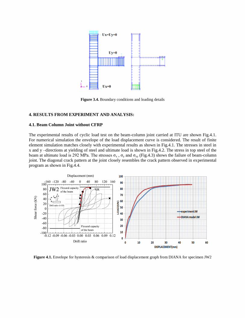
Figure 3.4. Boundary conditions and loading details
4. RESULTS FROM EXPERIMENT AND ANALYSIS:
4.1. Beam Column Joint without CFRP
The experimental results of cyclic load test on the beam-column joint carried at ITU are shown Fig.4.1.
For numerical simulation the envelope of the load displacement curve is considered. The result of finite
element simulation matches closely with experimental results as shown in Fig.4.1. The stresses in steel in
x and y –directions at yielding of steel and ultimate load is shown in Fig.4.2. The stress in top steel of the
beam at ultimate load is 292 MPa. The stresses σx , σy and σxy (Fig.4.3) shows the failure of beam-column
joint. The diagonal crack pattern at the joint closely resembles the crack pattern observed in experimental
program as shown in Fig.4.4.
Figure 4.1. Envelope for hysteresis & comparison of load displacement graph from DIANA for specimen JW2

Figure 4.2. Stress Sxx & Syy in steel from DIANA
Figure 4.3. Stresses Sxx, Syy & Sxy in concrete from DIANA
Figure 4.4. Crack patterns obtained from DIANA

4.2. Beam column joint strengthened with CFRP
The hysteresis envelopes obtained in experimental programs for the beam-column joint strengthened with
CFRP (Fig.2.2) in diagonal direction is shown in Fig.4.5. The stress in steel and CFRP is shown in
Fig.4.6. It can be seen that the maximum stresses occurred in CFRP for both σx and σy. The ultimate load
capacity of the beam-column joint strengthened by CFRP sheets increased by 13%. The stress in concrete
is shown in Fig.4.7. The shear stress in the joint decreases due to application of CFRP sheets. The crack
pattern of CFRP strengthened beam-column joint changes and failure occurs by cracking at beam column
interface with no significant cracking in the joint.
Figure 4.5. Envelope for hysteresis & comparison of load displacement graph from DIANA for specimen JWC-D-2
Figure 4.6. Stress Sxx & Syy in steel and CFRP from DIANA

Figure 4.7. Stresses syy & sxy in concrete from DIANA
Figure 4.8. Crack patterns obtained from DIANA
5. CONCLUSIONS
The general behavior of the finite element model represented by the load deflection shows good
agreement with the test data which indicates that DIANA software with its 2-D plane stress model is able
to capture the behavior of beam-column joint very well. The crack patterns at various loads from the finite
element model correspond well with the experimentally observed failure modes. Stresses in the beam,
column and joints are matchable and model predicts good result for stress which indicates that beam-
column joint is well modeled by Drucker-Prager with tension cut-off and tension softening. The finite
element model was able to capture the response of beam column joints strengthened by CFRP sheets. The
ultimate load capacity of CFRP strengthened beam-column joint is increased by 13% and the mode
failure changes from failure in the joint to failure at beam-column interface.
ACKNOWLEDGEMENT
The study is being funded by King Fahd University of Petroleum & Minerals under project number RG1111-1 &
RG1111-2. The support of Civil Engineering Department and Research Institute at KFUPM is gratefully
acknowledged. The authors acknowledge the technical support provided by ITU to the KFUPM graduate students
involved in this project.

REFERENCES
Bedirhanoglu, A.Ilki, S. Pujol, and N.Kumbasar. (2010). Behavior of deficient joints with plain bars and low
strength concrete. ACI Structural Journal. V. 107, No. 3
Bedirhanoglu A.Ilki, and Kumbasar N.. (2011). Behavior of frp retrofitted joints built with plan bars and low
strength concrete. Journal Of Composites For Construction ASCE. DOI: 10.1061/(ASCE)CC.1943-
5614.0000156.
Bing Li and Sudhakar A. Kulkarni. (2010). Seismic behavior of reinforced concrete exterior wide beam-column
joints. Journal of Structural Engineering ASCE , Reston, Virginia
De Witte, F.C., Kikstra, W.P. (2010). DIANA finite element analysis. User’s manual. Analysis Procedures. TNO
DIANA bv. Delft. Netherlands.
Ibrahim and Mahmood M.. (2009). Finite element modeling of reinforced concrete beams strengthened with FRP
laminates. European Journal Of Scientific Research. ISSN 1450-216x Vol.30 No.4 Pp.526-541
Supaviriyakita, Pimanmasa and Warnitchaib. (2008). Nonlinear finite element analysis of non-seismically detailed
interior reinforced concrete beam-column connection under reversed cyclic load. Scienceasia :34,049-058