FD220CV VER HD FD220CV VER HDVC5 FD220CV VER HDSDI …fdsavionics.com › wp-content › uploads ›...
23
Document Number: MAN – FD220CV VER (XXXXX) Rev: E Revision Date: 08/04/2017 Page 1 of 23 © 2017 FDS Avionics Corp. All Rights Reserved. TECHNICAL SUPPORT 470-239-7421 or FDSAvionics.com Installation and Operation Manual FD220CV VER HD FD220CV VER HDVC5 FD220CV VER HDSDI FD220CV VER HDCV 22” High-Definition Widescreen LCD
Transcript of FD220CV VER HD FD220CV VER HDVC5 FD220CV VER HDSDI …fdsavionics.com › wp-content › uploads ›...

Document Number:
MAN – FD220CV VER (XXXXX) Rev:
E
Revision Date: 08/04/2017
Page 1 of 23
© 2017 FDS Avionics Corp. All Rights Reserved.
TECHNICAL SUPPORT 470-239-7421 or FDSAvionics.com
Installation and Operation Manual
FD220CV VER HD
FD220CV VER HDVC5
FD220CV VER HDSDI
FD220CV VER HDCV
22” High-Definition Widescreen LCD

Document Number:
MAN – FD220CV VER (XXXXX) Rev:
E
Revision Date: 08/04/2017
Page 2 of 23
© 2017 FDS Avionics Corp. All Rights Reserved.
TECHNICAL SUPPORT 470-239-7421 or FDSAvionics.com
Table of Contents
General Information ........................................................................................... 4
Front View ........................................................................................................... 4
Additional Information ....................................................................................... 4
Specifications ..................................................................................................... 5
Installation Instructions ..................................................................................... 5
Rear Connector Orientation .............................................................................. 6
Power .................................................................................................................. 7
Wiring Instructions ............................................................................................. 7
Wiring Suggestions ............................................................................................ 7
S-Video/Composite and Audio Wiring .............................................................. 7
VGA Wiring ......................................................................................................... 8
RS-485 Wiring ..................................................................................................... 9
HDMI .................................................................................................................... 9
Power & Ground Wiring ................................................................................... 10
Power/Video ...................................................................................................... 10
RS-485 Control ................................................................................................. 11
RS-485 Network ................................................................................................ 12
HDSDI ................................................................................................................ 12
Operation Instructions ..................................................................................... 13
Button Controls ................................................................................................ 13
Remote Control Button .................................................................................... 14
Appendix A ....................................................................................................... 15
1. FD220CV VER HD/VER HDSDI (DB-25 Pinout) ....................................... 15
2. FD220CV VER HDVC5 (DB-25 Pinout) .................................................... 16
3. FD220CV VER HDSDI (BNC Pinout) ........................................................ 17
Document Number:
MAN – FD220CV VER (XXXXX) Rev:
E
Revision Date: 08/04/2017
Page 3 of 23
© 2017 FDS Avionics Corp. All Rights Reserved.
TECHNICAL SUPPORT 470-239-7421 or FDSAvionics.com
4. FD220CV VER HDCV (DB-25 Pinout) ...................................................... 18
Technical Drawing ....................................................................................... 19-20
Technical Support ............................................................................................ 21
Instructions for Continued Airworthiness...................................................... 21
Warranty ............................................................................................................ 22
Log of Revisions .............................................................................................. 23

Document Number:
MAN – FD220CV VER (XXXXX) Rev:
E
Revision Date: 08/04/2017
Page 4 of 23
© 2017 FDS Avionics Corp. All Rights Reserved.
TECHNICAL SUPPORT 470-239-7421 or FDSAvionics.com
General Information
The FD220CV VER HD/FD220CV VER HDVC5/FD220CV VER HDSDI/VER HDCV is a 1080p, 22” High-Definition Widescreen LCD which has features that allow installation in the smallest of mounting areas with the minimum of interface equipment. Built with retrofit aircraft integration in mind, this display can switch between up to five video input sources using an infrared remote.
Front View
Additional Information
The FD220CV VER HD utilizes FIVE video source inputs. They are in order of picture quality: (2) HDMI, 1080p, (Hi-Def video, such as Blu-Ray DVD or PlayStation 3), (1) VGA (computer graphics like Moving Maps), (1) S-Video and (1) Composite Video (DVD, camera or VCR). Both NTSC and PAL formats are auto-detected.
The FD220CV VER HDVC5 has the same design features as the VER HD but is designed to integrate with the FDS Avionics Corp. Cabin Management System Video Crosspoint Switch (FDVCS) for VGA over Cat5 wiring. In this configuration, (2) HDMI and (1) VGA are the only inputs available. (See Appendix A for wiring details.) It also works with the High-Definition Video Crosspoint Switch (FDHDVCS) in order to accept HD signals via Cat5 wiring. Contact your local FDS Avionics Corp. Sale Representative for further information on integrating an FD220CV VER HDVC5 into a Select CMS Cabin Management.
The FD220CV VER HDSDI has all of the same features as the VER HD but is designed to input HD video by using (2) BNC connectors mounted to the rear of the unit. Video inputs include (2) HDSDI, (1) VGA, (1) S-Video, and (1) Composite.
The LCD is protected with a .060” Lexan lens to prevent scratching of the LCD and reduce glare. FD220CV VER HD/VER HDVC5/VER HDSDI/VER HDCV is made of all metal components. DO-160 testing documents are available upon request.
Document Number:
MAN – FD220CV VER (XXXXX) Rev:
E
Revision Date: 08/04/2017
Page 5 of 23
© 2017 FDS Avionics Corp. All Rights Reserved.
TECHNICAL SUPPORT 470-239-7421 or FDSAvionics.com
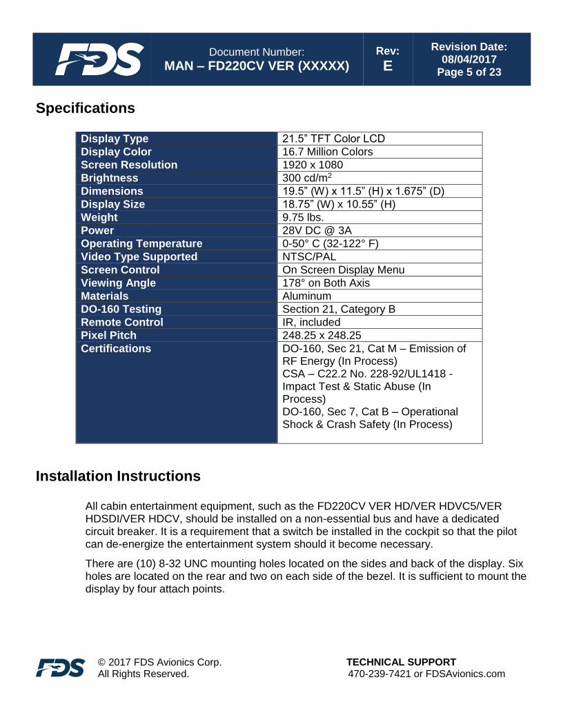
Specifications
Display Type 21.5” TFT Color LCD
Display Color 16.7 Million Colors
Screen Resolution 1920 x 1080
Brightness 300 cd/m2
Dimensions 19.5” (W) x 11.5” (H) x 1.675” (D)
Display Size 18.75” (W) x 10.55” (H)
Weight 9.75 lbs.
Power 28V DC @ 3A
Operating Temperature 0-50° C (32-122° F)
Video Type Supported NTSC/PAL
Screen Control On Screen Display Menu
Viewing Angle 178° on Both Axis
Materials Aluminum
DO-160 Testing Section 21, Category B
Remote Control IR, included
Pixel Pitch 248.25 x 248.25
Certifications
DO-160, Sec 21, Cat M – Emission of RF Energy (In Process) CSA – C22.2 No. 228-92/UL1418 - Impact Test & Static Abuse (In Process) DO-160, Sec 7, Cat B – Operational Shock & Crash Safety (In Process)
Installation Instructions
All cabin entertainment equipment, such as the FD220CV VER HD/VER HDVC5/VER HDSDI/VER HDCV, should be installed on a non-essential bus and have a dedicated circuit breaker. It is a requirement that a switch be installed in the cockpit so that the pilot can de-energize the entertainment system should it become necessary.
There are (10) 8-32 UNC mounting holes located on the sides and back of the display. Six holes are located on the rear and two on each side of the bezel. It is sufficient to mount the display by four attach points.
Document Number:
MAN – FD220CV VER (XXXXX) Rev:
E
Revision Date: 08/04/2017
Page 6 of 23
© 2017 FDS Avionics Corp. All Rights Reserved.
TECHNICAL SUPPORT 470-239-7421 or FDSAvionics.com
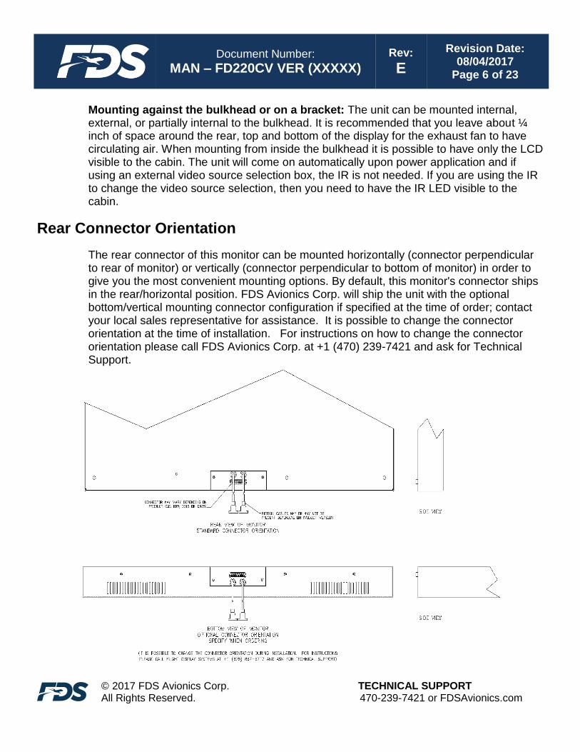
Mounting against the bulkhead or on a bracket: The unit can be mounted internal, external, or partially internal to the bulkhead. It is recommended that you leave about ¼ inch of space around the rear, top and bottom of the display for the exhaust fan to have circulating air. When mounting from inside the bulkhead it is possible to have only the LCD visible to the cabin. The unit will come on automatically upon power application and if using an external video source selection box, the IR is not needed. If you are using the IR to change the video source selection, then you need to have the IR LED visible to the cabin.
Rear Connector Orientation
The rear connector of this monitor can be mounted horizontally (connector perpendicular to rear of monitor) or vertically (connector perpendicular to bottom of monitor) in order to give you the most convenient mounting options. By default, this monitor's connector ships in the rear/horizontal position. FDS Avionics Corp. will ship the unit with the optional bottom/vertical mounting connector configuration if specified at the time of order; contact your local sales representative for assistance. It is possible to change the connector orientation at the time of installation. For instructions on how to change the connector orientation please call FDS Avionics Corp. at +1 (470) 239-7421 and ask for Technical Support.

Document Number:
MAN – FD220CV VER (XXXXX) Rev:
E
Revision Date: 08/04/2017
Page 7 of 23
© 2017 FDS Avionics Corp. All Rights Reserved.
TECHNICAL SUPPORT 470-239-7421 or FDSAvionics.com
Power
This is a 28V DC monitor that requires 3.0 Amps (84 watts) of power.
Wiring Suggestions
All shields should be grounded to the connector at the source, and floating at the display.
Avoid routing video wiring parallel to:
• AC wiring
• Strobe wiring
• DC motor supply cables
• Inverter cabling
• Or any other potential noise source
S-Video/Composite/Component Wiring
Recommended cable for s-video/composite and audio purposes is PIC 75 Ohm Coax, P/N V76261. This is a lightweight, flexible, and low signal loss cable which meets FAA flammability requirements of FAR 23.1359(d), FAR 25.853(a) and FAR 25.869(a)(4).
Similar aviation coaxial cable can be used from other vendors, as well.
Some aircraft are prone to AC noise - we recommend adding to the composite source a 75 Ohm video isolation transformer such as Deerfield Laboratory, Inc. Part No. 162-1 (www.deerfieldlab.com, (650) 632-4090). In most cases this should be added to the video output of the source.

Document Number:
MAN – FD220CV VER (XXXXX) Rev:
E
Revision Date: 08/04/2017
Page 8 of 23
© 2017 FDS Avionics Corp. All Rights Reserved.
TECHNICAL SUPPORT 470-239-7421 or FDSAvionics.com
VGA Wiring
Recommended cable for VGA purpose is ECS P/N 453005. This is a single shielded cable containing 5 separate coaxial cables, color-coded to match the functions of the wires.
We recommend coax cables be terminated using solder sleeve coaxial cable terminators such as Raychem Part Number CWT-4174-W122-5/9.

Document Number:
MAN – FD220CV VER (XXXXX) Rev:
E
Revision Date: 08/04/2017
Page 9 of 23
© 2017 FDS Avionics Corp. All Rights Reserved.
TECHNICAL SUPPORT 470-239-7421 or FDSAvionics.com
RS-485 Wiring
Shielded twisted-pair 22 AWG wire is recommended for RS-485 wiring.
HDMI
HDMI (High-Definition Multimedia Interface) defines the protocol and electrical specifications for the signalling, pin-out, electrical, and mechanical requirements of cable and connectors used for transmitting High-Definition content. The Type A HDMI connector (shown below) has 19 pins with bandwidth to support all SDTV, EDTV, and HDTV modes. The plug’s outside dimensions are 13.9 mm wide by 4.45 mm high.
ECS manufactures an HDMI cable that is terminated at the factory. It is ordered as part number 600-19786-XXX, where XXX is the length in inches for the desired cable.

Document Number:
MAN – FD220CV VER (XXXXX) Rev:
E
Revision Date: 08/04/2017
Page 10 of 23
© 2017 FDS Avionics Corp. All Rights Reserved.
TECHNICAL SUPPORT 470-239-7421 or FDSAvionics.com
Power and Ground Wiring
This is a 28VDC monitor that requires 3 amps of power to operate. To operate properly this monitor requires an input voltage of 24-29VDC.
The rated current of the equipment and associated voltage drop should be taken into consideration when selecting wire gauge. The following example is based on an install with a 28VDC power system and a total of 50 feet of wire between the circuit breaker, monitor and ground.
Example: 22awg wire has 16.2 Ohms per 1000 feet, this equates to .81 Ohms for 50 feet. 3 Amps of current on .81 Ohms will drop 2.43 Volts.
Resistance of Wire Type M22759/16-** (** = Gauge)
Gauge (AWG) OHMS/1000’
24 26.20
22 16.20
20 9.88
16 4.81
12 2.02
10 1.26
8 .70
Also, use short heavy gauge wire and a clean tight connection for ground.
It is the installer's responsibility to understand the product's requirements to install the product in compliance with industry standards and safety.
Power/Video
See Appendix A for Pinouts.

Document Number:
MAN – FD220CV VER (XXXXX) Rev:
E
Revision Date: 08/04/2017
Page 11 of 23
© 2017 FDS Avionics Corp. All Rights Reserved.
TECHNICAL SUPPORT 470-239-7421 or FDSAvionics.com
RS-485 Control (For FD220CV VER HD & VER HDVCD5 ONLY)
RS-485 is a two-wire communication interface that allows an external device such as a computer or switching unit to control the monitor’s functions remotely. Up to 99 monitors can be separately controlled by one unit.
Command sets for controlling the monitors with serial numbers starting w/ 12XXXXXXXX (10 digits) and above:
Commands
Length CMD Index Set ID Data Check Sum
Power On 0x08 0x12 0x9C 0x00 0x00 0x01 0x01 0x48
Power Off 0x08 0x12 0x9C 0x00 0x00 0x00 0x01 0x49
HDMI 1 0x08 0x12 0x8E 0x00 0x00 0x00 0x01 0x57
HDMI 2 0x08 0x12 0x8E 0x00 0x00 0x01 0x01 0x56
DVI 0x08 0x12 0x8E 0x00 0x00 0x02 0x01 0x55
VGA 0x08 0x12 0x8E 0x00 0x00 0x03 0x01 0x54
S-Video 0x08 0x12 0x8E 0x00 0x00 0x04 0x01 0x53
Composite 0x08 0x12 0x8E 0x00 0x00 0x05 0x01 0x52
Auto 0x08 0x12 0x7E 0x00 0x00 0x00 0x01 0x67
Full Screen 0x08 0x12 0x7E 0x00 0x00 0x01 0x01 0x66
16:9 0x08 0x12 0x7E 0x00 0x00 0x02 0x01 0x65
4:3 0x08 0x12 0x7E 0x00 0x00 0x03 0x01 0x64
1:1 0x08 0x12 0x7E 0x00 0x00 0x04 0x01 0x63
The RS-485 connector carries information between the Infrared received and the LCD controller board. Any connections to the RS-485 bus must be tolerant to the existing control signals. Devices connected to the RS-485 Bus should not send traffic that interferes with the existing RS-485 messages.
Notes:
1. The first nine characters will remain the same for any command. 2. For connecting multiple monitors to one controller; the number can be set to0x00 to control all
monitors at once, 0x01 to control monitor number 1, 0x02 monitor number 2, and so on until 0x63 for monitor number 99.
3. The number will change depending on command. 4. Identifier for the group of commands. 5. All commands need to end with a Carriage Return

Document Number:
MAN – FD220CV VER (XXXXX) Rev:
E
Revision Date: 08/04/2017
Page 12 of 23
© 2017 FDS Avionics Corp. All Rights Reserved.
TECHNICAL SUPPORT 470-239-7421 or FDSAvionics.com
RS-485 Network:
If there is more than one monitor connected to the aircraft’s RS-485 controller system, it is strongly recommended to connect the system in series, or daisy-chain, and terminate the twisted pairs with a 120 OHM resistor. This configuration improves the reliability of the system.
It is highly recommended to use 22 AWG twisted pairs for runs longer than 20 feet. Connect all RS-485A pins together, all RS-485B pins together.
HD-SDI HD-SDI Input & HD-SDI Output are panel mounted BNC receptacles that mate with standard BNC plugs (Amphenol P/N 31-242 supplied).

Document Number:
MAN – FD220CV VER (XXXXX) Rev:
E
Revision Date: 08/04/2017
Page 13 of 23
© 2017 FDS Avionics Corp. All Rights Reserved.
TECHNICAL SUPPORT 470-239-7421 or FDSAvionics.com
Operation Instructions
The FD220CV VER HD/VER HDVC5/VER HDSDI/VER HDCV is continuously on but can be de-energized by removing power from the entertainment system. No pilot or aircrew action is necessary during flight or ground operation.
The passengers will be able to change the video output from the unit using the video source select switch on the LCD monitor, or remotely throughout the cabin with the included IR remote. Point the IR remote at the top of the LCD to make changes.
When applying 28VDC power, the display will turn on and look for a valid input on the last known source. If no input is found, the display will go to standby mode. Pressing the Select button will select new video input.
Button Controls
Located at the top (center) of the FD220CV VER HD/VER HDVC5/VER HDSDI/VER HDCV are 8 buttons. Their functions are shown below:
BUTTON DESCRIPTION
POWER Toggles the power ON or OFF. Also, wakes the display up from SLEEP mode.
MENU Opens the MENU.
AUTO Auto-adjusts the display’s size and position.
DOWN Moves to the next selection in the menu.
UP Moves to the previous selection in the menu.
LEFT Decrease the selection’s value in the menu.
RIGHT Increases the selection’s value in the menu.
SOURCE Switches between sources coming into the display.

Document Number:
MAN – FD220CV VER (XXXXX) Rev:
E
Revision Date: 08/04/2017
Page 14 of 23
© 2017 FDS Avionics Corp. All Rights Reserved.
TECHNICAL SUPPORT 470-239-7421 or FDSAvionics.com
Remote Control Buttons
Refer to Button Controls on previous page.
Remote required for FD220CV VER HDSDI
Remote required for FD220CV VER HD & FD220CV VER HDVC5

Document Number:
MAN – FD220CV VER (XXXXX) Rev:
E
Revision Date: 08/04/2017
Page 15 of 23
© 2017 FDS Avionics Corp. All Rights Reserved.
TECHNICAL SUPPORT 470-239-7421 or FDSAvionics.com
Appendix A
FD220CV VER HD/ FD220CV VER HDSDI - Pin out for P1 (DB-25 Receptacle) Connector P/N: M24308/2-283 or Equivalent Crimp Contacts P/N: M39029/63-368 or Equivalent
Pin Number
Description
1 28VDC Power
2 28VDC Ground
3 28VDC Power
4 28VDC Ground
5 Composite Video – Signal
6 Composite Video – Shield
7 S-Video Y – Signal
8 S-Video – Shield
9 S-Video C – Signal
10 S-Video C – Shield
11 Red Video (Pin 1 on Standard VGA)
12 Green Video (Pin 2 on Standard VGA)
13 Blue Video (Pin 3 on Standard VGA)
14 N/C
15 N/C
16 Red Ground (Pin 6 on Standard VGA)
17 Green Ground (Pin 7 on Standard VGA)
18 N/C
19 N/C
20 RS-485 Input A (HD Version Only)
21 RS-485 Input B (HD Version Only)
22 N/C
23 Horizontal Sync (Pin 13 on Standard VGA)
24 Vertical Sync (Pin 14 on Standard VGA)
25 N/C

Document Number:
MAN – FD220CV VER (XXXXX) Rev:
E
Revision Date: 08/04/2017
Page 16 of 23
© 2017 FDS Avionics Corp. All Rights Reserved.
TECHNICAL SUPPORT 470-239-7421 or FDSAvionics.com
FD220CV VER HDVC5 - Pinout for P1 (DB-25 Receptacle)
Connector P/N: M24308/2-283 or Equivalent Crimp Contacts P/N: M39029/63-368 or Equivalent
Pin Number
Description
1 28VDC Power
2 28VDC Ground
3 28VDC Power
4 28VDC Ground
5 N/C
6 N/C
7 N/C
8 N/C
9 N/C
10 N/C
11 Red (-) (T568B Cat5 Pin 1)
12 Red (+) (T568B Cat5 Pin 2)
13 Blue (-) (T568B Cat5 Pin 3)
14 28VDC Power
15 28VDC Ground
16 Blue (+) (T568B Cat5 Pin 6)
17 Green (-) (T568B Cat5 Pin 5)
18 N/C
19 N/C
20 RS-485 Input A
21 RS-485 Input B
22 N/C
23 Green (+) (T568B Cat5 Pin 4)
24 Ground (T568B Cat5 Pin 8)
25 N/C

Document Number:
MAN – FD220CV VER (XXXXX) Rev:
E
Revision Date: 08/04/2017
Page 17 of 23
© 2017 FDS Avionics Corp. All Rights Reserved.
TECHNICAL SUPPORT 470-239-7421 or FDSAvionics.com
Note: Cat5 Pin 7 is not used
FD220CV VER HDSDI - Pin out for HD-SDI Input (Standard BNC – 75 OHM) – 31-242 (Supplied)
Pin Description
Center Video Signal
Shell Video Return
Document Number:
MAN – FD220CV VER (XXXXX) Rev:
E
Revision Date: 08/04/2017
Page 18 of 23
© 2017 FDS Avionics Corp. All Rights Reserved.
TECHNICAL SUPPORT 470-239-7421 or FDSAvionics.com
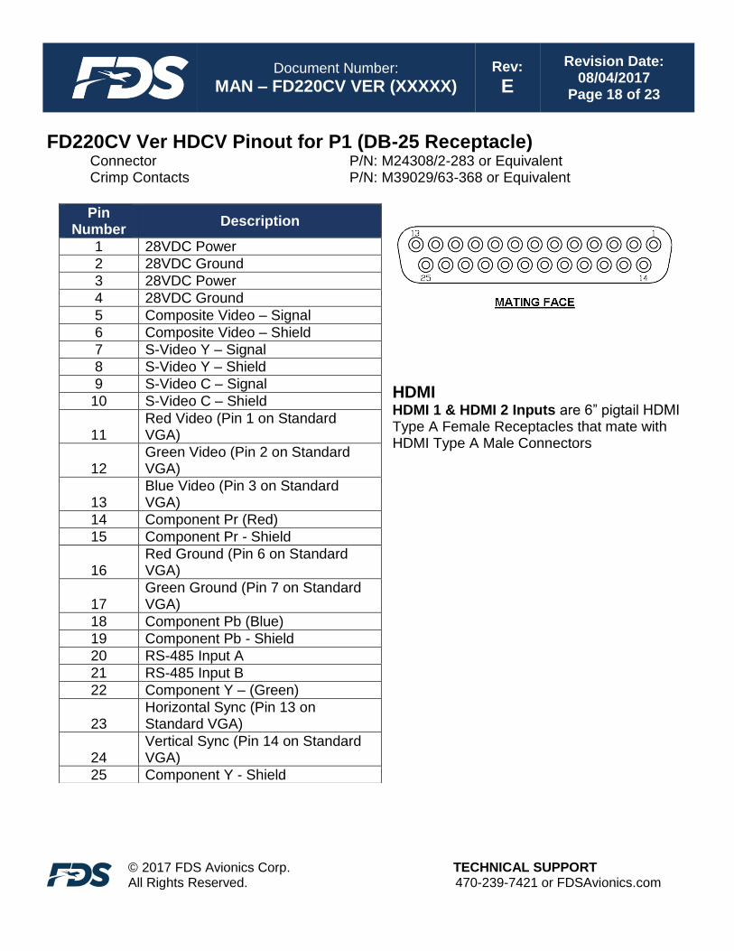
FD220CV Ver HDCV Pinout for P1 (DB-25 Receptacle) Connector P/N: M24308/2-283 or Equivalent Crimp Contacts P/N: M39029/63-368 or Equivalent
HDMI HDMI 1 & HDMI 2 Inputs are 6” pigtail HDMI Type A Female Receptacles that mate with HDMI Type A Male Connectors
Pin Number
Description
1 28VDC Power
2 28VDC Ground
3 28VDC Power
4 28VDC Ground
5 Composite Video – Signal
6 Composite Video – Shield
7 S-Video Y – Signal
8 S-Video Y – Shield
9 S-Video C – Signal
10 S-Video C – Shield
11 Red Video (Pin 1 on Standard VGA)
12 Green Video (Pin 2 on Standard VGA)
13 Blue Video (Pin 3 on Standard VGA)
14 Component Pr (Red)
15 Component Pr - Shield
16 Red Ground (Pin 6 on Standard VGA)
17 Green Ground (Pin 7 on Standard VGA)
18 Component Pb (Blue)
19 Component Pb - Shield
20 RS-485 Input A
21 RS-485 Input B
22 Component Y – (Green)
23 Horizontal Sync (Pin 13 on Standard VGA)
24 Vertical Sync (Pin 14 on Standard VGA)
25 Component Y - Shield

Document Number:
MAN – FD220CV VER (XXXXX) Rev:
E
Revision Date: 08/04/2017
Page 19 of 23
© 2017 FDS Avionics Corp. All Rights Reserved.
TECHNICAL SUPPORT 470-239-7421 or FDSAvionics.com
Technical Drawing

Document Number:
MAN – FD220CV VER (XXXXX) Rev:
E
Revision Date: 08/04/2017
Page 20 of 23
© 2017 FDS Avionics Corp. All Rights Reserved.
TECHNICAL SUPPORT 470-239-7421 or FDSAvionics.com
Technical Drawing
Document Number:
MAN – FD220CV VER (XXXXX) Rev:
E
Revision Date: 08/04/2017
Page 21 of 23
© 2017 FDS Avionics Corp. All Rights Reserved.
TECHNICAL SUPPORT 470-239-7421 or FDSAvionics.com
Technical Support
Should you have any questions concerning this product or other FDS Avionics Corp. products, please contact our Product Support representatives at 470-239-7421.
FDS Avionics Corp. 6435 Shiloh Road Alpharetta, GA 30005 Phone: 470-239-7400 Fax: 470-239-7439 Email: [email protected]
For further product information, technical data and sample wiring diagrams, please click on the Dealers section of our web site at www.FDSAvionics.com
Instructions for Continued Airworthiness
The FD220CV VER HD/VER HDVC5/VER HDSDI/VER HDCV is designed not to require regular general maintenance.

Document Number:
MAN – FD220CV VER (XXXXX) Rev:
E
Revision Date: 08/04/2017
Page 22 of 23
© 2017 FDS Avionics Corp. All Rights Reserved.
TECHNICAL SUPPORT 470-239-7421 or FDSAvionics.com
Limited Warranty All FDS Avionics Corp. products are warranted to be free from material or manufacturing defects for a period of 24 months from the date of shipment for General Aviation customers or 12 months from the date of shipment for Government/Special Mission customers. Any material or repair workmanship for in warranty repair service will be specifically warranted for 90 days or the remainder of the original warranty period, whichever is longer. If the original warranty period has expired, the 90-day repair warranty is limited to the material and workmanship specific to the repair activity completed.
The following conditions are exclusions to warranty coverage:
1. Labor costs associated with installation, removal or reinstallation of any product. 2. Damage to or malfunction caused by any unauthorized alteration made to the product. 3. Resolving signal quality issues caused by externally generated noise introduced by aircraft electrical
systems or other components connected to any FDS product. 4. Any malfunction caused by improper installation or connection to aircraft wiring, industry standard cabin
management/inflight entertainment systems, or third party commercial equipment not specifically identified as compatible with FDS products.
5. Any malfunction caused by installation that does not conform to precautions associated with operating environments listed in the operating manual or consistent with industry best practices such as high temperature, adequate ventilation, high humidity, high dust, or power surges.
6. Cosmetic damage or damage to internal components caused by installation or removal, failure to follow installation or operating instructions, or any neglect or misuse of the product.
7. Any product that is returned for service with a broken tamper evident seal, indicating tampering or improper handling of the product by an unauthorized person. Violation of product tamper evident seals or modification of factory installed serial and PMA labels voids any warranty, either expressed or implied.
The FDS Technical Support team is available to provide distance troubleshooting support during business hours (8:00am to 5:00pm EST) Monday through Friday at (470) 239-7421. Many repair requests can be resolved through distance support and may not require return of merchandise to the factory. If a product must be returned to the factory for repair, an RMA number will be issued as directed by the Technical Support team and communicated by the Repair Coordinator. Upon request by the customer, FDS may send a Service Technician onsite to repair any non-PMA products. The travel expenses incurred to include transportation, lodging and meals along with the technician’s hourly rate shall be payable by the customer in accordance with FDS’ applicable rates and procedures. FDS Avionics Corp. will, upon receipt of returned merchandise, remanufacture or replace the unit at our discretion and return the product by Ground Return Shipping. Express return shipment will be the responsibility of the sender. This warranty is not transferable. Any implied warranties expire at the express limited warranty expiration date. FDS shall not be held liable for any indirect, special, punitive, incidental or consequential damages. Some states do not allow limitation on the length of an implied warranty. In such states, the exclusions or limitations of this limited warranty may not apply.

Document Number:
MAN – FD220CV VER (XXXXX) Rev:
E
Revision Date: 08/04/2017
Page 23 of 23
© 2017 FDS Avionics Corp. All Rights Reserved.
TECHNICAL SUPPORT 470-239-7421 or FDSAvionics.com
Log of Revisions
Rev Date Page Description
A 04/08/2011 Initial Release
B 07/21/2011 Added FD220CV VER HDCV
C 07/01/2012 Update format
D 05/23/2014 Updated RS-485 Command Set, Address Data, Warranty Information.
E 08/04/2017 New Format, New Company, New Branding, Updated VGA wiring diagram