FDCONV-HDSDI-D VER SW FDCONV-HDSDI-S VER SWfdsavionics.com/wp-content/uploads/2017/05/FDCONV... ·...
13
Document Number: MAN – FDCONV-HDSDI-D(-S) VER SW Rev: F Revision Date: 05/05/2017 Page 1 of 13 © 2017 FDS Avionics Corp. All Rights Reserved. TECHNICAL SUPPORT 470-239-7421 or FDSAvionics.com Installation and Operation Manual FDCONV-HDSDI-D VER SW FDCONV-HDSDI-S VER SW HDSDI Converter
Transcript of FDCONV-HDSDI-D VER SW FDCONV-HDSDI-S VER SWfdsavionics.com/wp-content/uploads/2017/05/FDCONV... ·...
Document Number:
MAN – FDCONV-HDSDI-D(-S) VER SW
Rev:
F
Revision Date: 05/05/2017
Page 1 of 13
© 2017 FDS Avionics Corp. All Rights Reserved.
TECHNICAL SUPPORT 470-239-7421 or FDSAvionics.com
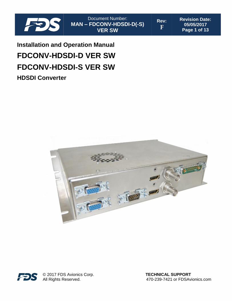
Installation and Operation Manual
FDCONV-HDSDI-D VER SW
FDCONV-HDSDI-S VER SW
HDSDI Converter

Document Number:
MAN – FDCONV-HDSDI-D(-S) VER SW
Rev:
F
Revision Date: 05/05/2017
Page 2 of 13
© 2017 FDS Avionics Corp. All Rights Reserved.
TECHNICAL SUPPORT 470-239-7421 or FDSAvionics.com
Table of Contents
General Information .................................................................................................................3
Functionality ..............................................................................................................................3
Front View ..................................................................................................................................3
Specifications .............................................................................................................................4
Installation Instructions .........................................................................................................5
Pinout ...................................................................................................................................... 6-8
Technical Drawing.............................................................................................................. 9-10
Technical Support ...................................................................................................................11
Instructions for Continued Airworthiness ........................................................................11
Warranty ...................................................................................................................................12
Log of Revisions ......................................................................................................................13
Document Number:
MAN – FDCONV-HDSDI-D(-S) VER SW
Rev:
F
Revision Date: 05/05/2017
Page 3 of 13
© 2017 FDS Avionics Corp. All Rights Reserved.
TECHNICAL SUPPORT 470-239-7421 or FDSAvionics.com
General Information
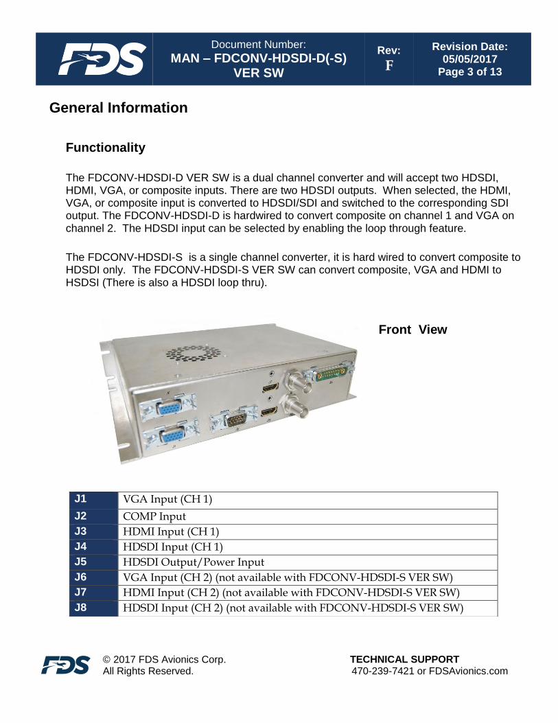
Functionality
The FDCONV-HDSDI-D VER SW is a dual channel converter and will accept two HDSDI, HDMI, VGA, or composite inputs. There are two HDSDI outputs. When selected, the HDMI, VGA, or composite input is converted to HDSDI/SDI and switched to the corresponding SDI output. The FDCONV-HDSDI-D is hardwired to convert composite on channel 1 and VGA on channel 2. The HDSDI input can be selected by enabling the loop through feature.
The FDCONV-HDSDI-S is a single channel converter, it is hard wired to convert composite to HDSDI only. The FDCONV-HDSDI-S VER SW can convert composite, VGA and HDMI to HSDSI (There is also a HDSDI loop thru).
Front View
J1 VGA Input (CH 1)
J2 COMP Input
J3 HDMI Input (CH 1)
J4 HDSDI Input (CH 1)
J5 HDSDI Output/Power Input
J6 VGA Input (CH 2) (not available with FDCONV-HDSDI-S VER SW)
J7 HDMI Input (CH 2) (not available with FDCONV-HDSDI-S VER SW)
J8 HDSDI Input (CH 2) (not available with FDCONV-HDSDI-S VER SW)
Document Number:
MAN – FDCONV-HDSDI-D(-S) VER SW
Rev:
F
Revision Date: 05/05/2017
Page 4 of 13
© 2017 FDS Avionics Corp. All Rights Reserved.
TECHNICAL SUPPORT 470-239-7421 or FDSAvionics.com
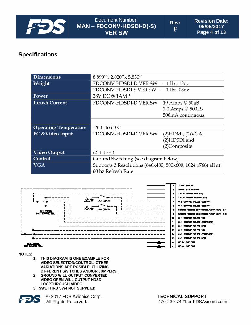
Specifications
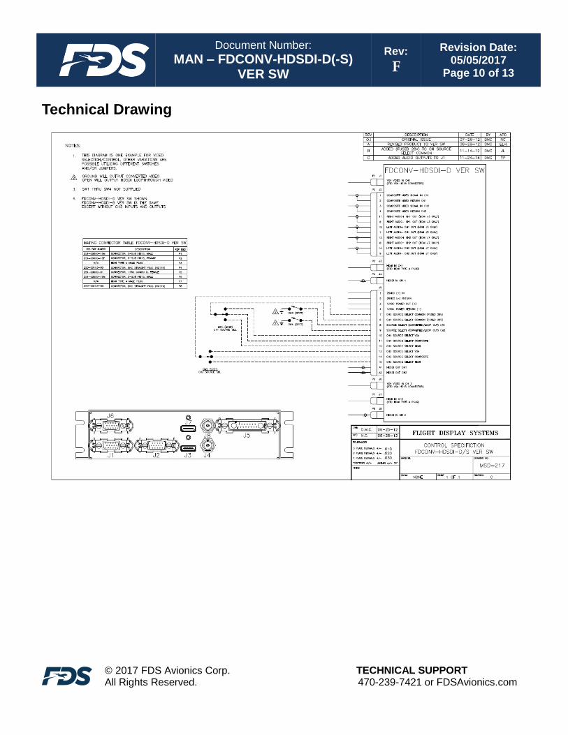
NOTES:
1. THIS DIAGRAM IS ONE EXAMPLE FOR VIDEO SELECTION/CONTROL, OTHER VARIATIONS ARE POSIBLE UTILIZING DIFFERENT SWITCHES AND/OR JUMPERS.
2. GROUND WILL OUTPUT CONVERTED VIDEO OPEN WILL OUTPUT HDSDI LOOPTHROUGH VIDEO
3. SW1 THRU SW4 NOT SUPPLIED
Dimensions 8.890’’x 2.020’’x 5.830’’
Weight FDCONV-HDSDI-D VER SW - 1 lbs. 12oz.
FDCONV-HDSDI-S VER SW - 1 lbs. 08oz Power 28V DC @ 1AMP
Inrush Current FDCONV-HDSDI-D VER SW 19 Amps @ 50µS 7.0 Amps @ 500µS 500mA continuous
Operating Temperature -20 C to 60 C
PC &Video Input FDCONV-HDSDI-D VER SW (2)HDMI, (2)VGA, (2)HDSDI and (2)Composite
Video Output (2) HDSDI Control Ground Switching (see diagram below)
VGA Supports 3 Resolutions (640x480, 800x600, 1024 x768) all at 60 hz Refresh Rate
Document Number:
MAN – FDCONV-HDSDI-D(-S) VER SW
Rev:
F
Revision Date: 05/05/2017
Page 5 of 13
© 2017 FDS Avionics Corp. All Rights Reserved.
TECHNICAL SUPPORT 470-239-7421 or FDSAvionics.com
Installation Instructions All cabin electronic equipment that is not required for flight, such as the FDCONV-HDSDI-D/S
VER SW, should be installed on a non-essential bus and have a dedicated circuit breaker.
Mechanical Installation The unit may be mounted in a horizontal or vertical position on an equipment rack or inside a cabinet. It is recommended to install with at least 1 inch of space around the top and left & right sides of the unit to allow circulation of air for cooling.
HDSDI HDSDI Input is a panel mounted BNC receptacle that mates with a standard BNC plug (RG179 Connector supplied).
HDMI HDMI Input is a flush mounted HDMI Type A Female Receptacle that mates with a HDMI Type A Male Connector(not supplied). All other mating connectors are provided by FDS Avionics Corp..
Video Selection
Video selection is made by enabling or disabling a ground circuit. An open circuit on the loop
outsource select (P2 pin 8 for CH1 & P2 pin 9 for CH2) will enable the HDSDI loop through.
When switched to ground the VGA, HDMI or Composite input can be enabled by applying a
ground to the corresponding source select pin (pin 10, 11, 12 for CH1 and 13,14, 15 for CH2).

Document Number:
MAN – FDCONV-HDSDI-D(-S) VER SW
Rev:
F
Revision Date: 05/05/2017
Page 6 of 13
© 2017 FDS Avionics Corp. All Rights Reserved.
TECHNICAL SUPPORT 470-239-7421 or FDSAvionics.com
Pinout
P1 & P6 – Standard VGA (Supplied)
Connector P/N: M24308/4-264 or Equivalent Crimp Contacts P/N: M39029/58-360 or Equivalent
Pin Number
Description
1 Red
2 Green
3 Blue
4 RES
5 GND
6 RGND
7 GGND
8 BGND
9 KEY
10 SGND
11 IDO
12 SDA
13 HSYNC OR CSYNC
14 VSYNC
15 SCL

Document Number:
MAN – FDCONV-HDSDI-D(-S) VER SW
Rev:
F
Revision Date: 05/05/2017
Page 7 of 13
© 2017 FDS Avionics Corp. All Rights Reserved.
TECHNICAL SUPPORT 470-239-7421 or FDSAvionics.com
P2 - High Density DB-15 Receptacle (Supplied) Connector P/N: M24308/2-286 or Equivalent Crimp Contacts P/N: M39029/57-354 or Equivalent
Pin Number
Description
1 Composite Video Signal CH1 IN
2 Composite Video Return CH1
3 Composite Video Signal CH2 IN
4 Composite Video Return CH2
5 N/C
6 J3 Right Audio -
7 J3 Left Audio -
8 J7 Right Audio -
9 J7 Left Audio -
10 N/C
11 J3 Right Audio +
12 J3 Left Audio +
13 J7 Right Audio+
14 J7 Left Audio +
15 N/C

Document Number:
MAN – FDCONV-HDSDI-D(-S) VER SW
Rev:
F
Revision Date: 05/05/2017
Page 8 of 13
© 2017 FDS Avionics Corp. All Rights Reserved.
TECHNICAL SUPPORT 470-239-7421 or FDSAvionics.com
P3 & P7 - HDMI Type A Male Plug (Not supplied) P4 & P8 - Standard 75Ω BNC Plug (RG179 connector supplied)
Pin Description
Center Video Signal
Shell Video Return
P5 - 17W2 Combo-D Receptacle (Supplied w/ RG179 contacts) Connector Conec P/N: 3017W2SCM99A10X Coax Contacts Conec P/N: 132J30019X Signal Contacts Solder Cups
Pin Number
Description
1 28VDC Power IN
2 28V Power Return
3 12VDC Power OUT
4 12VDC Power Return
5 N/C
6 CH1 Source Select Common
7 CH2 Source Select Common
8 Source Select (Converted/Loop Out) CH1
9 Source Select (Converted/Loop Out) CH2
10 CH1 Source Select VGA
11 CH1 Source Select Composite
12 CH1 Source Select HDMI
13 CH2 Source Select VGA
14 CH2 Source Select Composite
15 CH2 Source Select HDMI
A1 HDSDI OUT CH1
A2 HDSDI OUT CH2
Document Number:
MAN – FDCONV-HDSDI-D(-S) VER SW
Rev:
F
Revision Date: 05/05/2017
Page 9 of 13
© 2017 FDS Avionics Corp. All Rights Reserved.
TECHNICAL SUPPORT 470-239-7421 or FDSAvionics.com
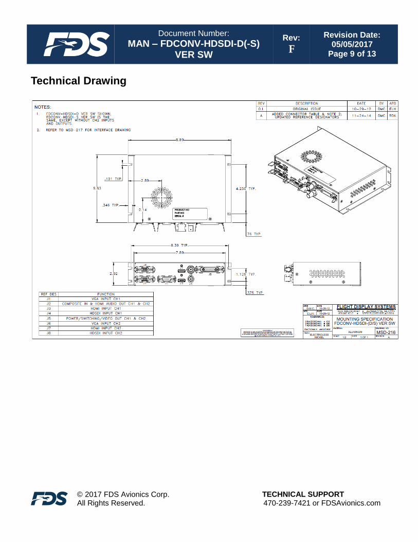
Technical Drawing
Document Number:
MAN – FDCONV-HDSDI-D(-S) VER SW
Rev:
F
Revision Date: 05/05/2017
Page 10 of 13
© 2017 FDS Avionics Corp. All Rights Reserved.
TECHNICAL SUPPORT 470-239-7421 or FDSAvionics.com
Technical Drawing
Document Number:
MAN – FDCONV-HDSDI-D(-S) VER SW
Rev:
F
Revision Date: 05/05/2017
Page 11 of 13
© 2017 FDS Avionics Corp. All Rights Reserved.
TECHNICAL SUPPORT 470-239-7421 or FDSAvionics.com
Technical Support
Should you have any questions concerning this product or other FDS Avionics Corp. products, please contact our Product Support representatives at (470) 239-7421.
FDS Avionics Corp. 6435 Shiloh Road Alpharetta, GA 30005 Phone: 470-239-7400 Fax: 470-239-7439 Email: [email protected]
For further product information, technical data and sample wiring diagrams, please click on the Dealers section of our web site at www.FDSAvionics.com
Instructions for Continued Airworthiness
The FDCONV-HDSDI-D/S VER SW converter is designed not to require regular general maintenance.

Document Number:
MAN – FDCONV-HDSDI-D(-S) VER SW
Rev:
F
Revision Date: 05/05/2017
Page 12 of 13
© 2017 FDS Avionics Corp. All Rights Reserved.
TECHNICAL SUPPORT 470-239-7421 or FDSAvionics.com
Warranty Information
All FDS Avionics Corp. (FDS) products are warranted to be free from material or manufacturing defects for a period of 24 months from the date of shipment for General Aviation customers or 12 months from the date of shipment for Government/Special Mission customers. Any material or repair workmanship for in warranty repair service will be specifically warranted for 90 days or the remainder of the original warranty period, whichever is longer. If the original warranty period has expired, the 90 day repair warranty is limited to the material and workmanship specific to the repair activity completed.
The following conditions are exclusions to warranty coverage:
1. Labor costs associated with installation, removal or reinstallation of any product. 2. Damage to or malfunction caused by any unauthorized alteration made to the product. 3. Resolving signal quality issues caused by externally generated noise introduced by aircraft electrical
systems or other components connected to any FDS product. 4. Any malfunction caused by improper installation or connection to aircraft wiring, industry standard cabin
management/ inflight entertainment systems, or third party commercial equipment not specifically identified as compatible with FDS products.
5. Any malfunction caused by installation that does not conform to precautions associated with operating environments listed in the operating manual or consistent with industry best practices such as; high temperature, adequate ventilation, high humidity, high dust, or power surges.
6. Cosmetic damage or damage to internal components caused by installation or removal, failure to follow installation or operating instructions, or any neglect or misuse of the product.
7. Any product that is returned for service with a broken tamper evident seal, indicating tampering or improper handling of the product by an unauthorized person. Violation of product tamper evident seals or modification of factory installed serial and PMA labels voids any warranty, either expressed or implied.
The FDS technical support team is available to provide distance troubleshooting support during business hours (8:00am to 5:00pm EST) Monday through Friday at (470) 239-7421. Many repair requests can be resolved through distance support and may not require return of merchandise to the factory. If a product must be returned to the factory for repair, an RMA number will be issued as directed by the technical support team and communicated by the repair coordinator. Upon request by the customer, FDS may send a service technician onsite to repair any non-PMA products. The travel expenses incurred to include transportation, lodging and meals along with the technician’s hourly rate shall be payable by the customer in accordance with FDS’ applicable rates and procedures. FDS Avionics Corp. will, upon receipt of returned merchandise, remanufacture or replace the unit at our discretion and return the product by Ground Return Shipping. Express return shipment will be the responsibility of the sender. This warranty is not transferable. Any implied warranties expire at the express limited warranty expiration date. FDS shall not be held liable for any indirect, special, punitive, incidental or consequential damages. Some states do not allow limitation on the length of an implied warranty. In such states, the exclusions or limitations of this limited warranty may not apply.

Document Number:
MAN – FDCONV-HDSDI-D(-S) VER SW
Rev:
F
Revision Date: 05/05/2017
Page 13 of 13
© 2017 FDS Avionics Corp. All Rights Reserved.
TECHNICAL SUPPORT 470-239-7421 or FDSAvionics.com
Revisions Log
Rev Date Page Description
A 7/20/2012 Initial Release
B 7/26/2013 All Name/Version Changed, Address, Contact and Warranty Information changed.
C 11/20/2013 5 Added VGA Supporting Resolutions
D 07/11/2014 7 Added Audio to pinout.
E 12/12/2014 All Updated MSDs and pinout information.
F 5/5/2017 All Update to Format, Warranty and Company Name.