FC7xx / FT724 Fire control panel / Fire terminal ...api.ivv-aut.com/adp/30 - DETECÇÃO...
164
A6V10211076_h_en_-- Building Technologies 2014-03-27 Control Products and Systems FC7xx / FT724 Fire control panel / Fire terminal Operation Manual IP5
Transcript of FC7xx / FT724 Fire control panel / Fire terminal ...api.ivv-aut.com/adp/30 - DETECÇÃO...
A6V10211076_h_en_-- Building Technologies2014-03-27 Control Products and Systems
FC7xx / FT724
Fire control panel / Fire terminal
Operation ManualIP5

Legal notice
2Building Technologies A6V10211076_h_en_--Fire Safety 2014-03-27
Legal noticeTechnical specifications and availability subject to change without notice.© 2008-2014 Copyright by Siemens Switzerland Ltd
Transmittal, reproduction, dissemination and/or editing of this document as well asutilization of its contents and communication thereof to others without expressauthorization are prohibited. Offenders will be held liable for payment of damages.All rights created by patent grant or registration of a utility model or design patentare reserved.
Issued by:Siemens Switzerland Ltd.Infrastructure & Cities SectorBuilding Technologies DivisionInternational HeadquartersGubelstrasse 22CH-6301 ZugTel. +41 41 724-2424www.siemens.com/buildingtechnologies
Edition: 2014-03-27Document ID: A6V10211076_h_en_--

3Building Technologies A6V10211076_h_en_--Fire Safety 2014-03-27
Table of contents
1 About this document ......................................................................................71.1 Applicable documents .......................................................................................81.2 Download center...............................................................................................81.3 Technical terms ................................................................................................91.4 History of changes ............................................................................................91.5 How displays are represented in the document ............................................... 10
2 Safety ............................................................................................................ 112.1 Safety instructions .......................................................................................... 112.2 Safety regulations for the method of operation ................................................ 122.3 Standards and directives complied with .......................................................... 142.4 Release Notes ................................................................................................ 14
3 PMI ................................................................................................................ 153.1 Buttons on the PMI ......................................................................................... 16
3.1.1 Standard keys .................................................................................. 163.1.2 Other alarms .................................................................................... 173.1.3 Softkeys........................................................................................... 173.1.4 Navigation buttons ........................................................................... 183.1.5 Keypad ............................................................................................ 193.1.6 Menu button..................................................................................... 193.1.7 Button 'ok' ........................................................................................ 193.1.8 Button 'C' ......................................................................................... 20
3.2 EVAC NL ........................................................................................................ 203.2.1 Functions on the EVAC PMI ............................................................. 21
3.3 Display ........................................................................................................... 213.3.1 Normal view ..................................................................................... 223.3.2 Extended view ................................................................................. 233.3.3 Fire department view ....................................................................... 233.3.4 Display with window and list ............................................................. 233.3.5 Display with window and input field .................................................. 243.3.6 Display with window and command response ................................... 24
3.4 LEDs .............................................................................................................. 253.5 Key switch (optional) ....................................................................................... 253.6 Menu structure ............................................................................................... 263.7 Cerberus Remote ........................................................................................... 273.8 Cerberus Mobile ............................................................................................. 28
4 Operation functions ...................................................................................... 294.1 Selection and opening / execution................................................................... 294.2 Scrolling ......................................................................................................... 294.3 Indication of the position and length of the list ................................................. 304.4 Shortcut .......................................................................................................... 304.5 Favorites ........................................................................................................ 304.6 Entry of numbers and letters ........................................................................... 31
4Building Technologies A6V10211076_h_en_--Fire Safety 2014-03-27
4.7 Cerberus Remote operating modes ................................................................ 314.8 Cerberus Mobile operation modes .................................................................. 32
5 Operation ...................................................................................................... 335.1 ALARM Procedure .......................................................................................... 335.2 Procedure in case of Fault .............................................................................. 355.3 Switching off / Switching on ............................................................................ 36
5.3.1 Switching a detector zone off / on .................................................... 365.3.2 Switching a detector off / on ............................................................. 395.3.3 Temporary switching-off ................................................................... 425.3.4 Switching off / on the remote transmission Fire ................................ 455.3.5 Switching off alarm activation ........................................................... 485.3.6 Switching off sabotage evaluation [DE] ............................................ 49
5.4 Log in / Change access level .......................................................................... 495.5 Logging out from an access level .................................................................... 505.6 Switching between 'Manned' / 'Unmanned' operation modes ........................... 505.7 Changing visibility ........................................................................................... 52
5.7.1 Deactivating standby........................................................................ 525.7.2 Activating / deactivating expanded visibility ...................................... 52
5.8 Main menu / Open menu item ......................................................................... 535.9 Execute commands – Basics .......................................................................... 54
5.9.1 Execute commands – General ......................................................... 545.9.2 Execute commands – object-oriented .............................................. 565.9.3 Executing commands – function-oriented ......................................... 585.9.4 Hide command confirmation message.............................................. 58
5.10 Selecting elements or events .......................................................................... 595.10.1 Select events ................................................................................... 595.10.2 Selection in the topology .................................................................. 605.10.3 Searching for elements .................................................................... 61
5.11 Testing ........................................................................................................... 645.11.1 Testing detectors ............................................................................. 645.11.2 Carry out 'Installation test' ................................................................ 655.11.3 Control test ...................................................................................... 655.11.4 Testing indicators ............................................................................. 66
5.12 Activation / Deactivation / Reset...................................................................... 675.12.1 Activating an alarm indicator (AI) ...................................................... 675.12.2 Deactivating / Activating alarm devices ............................................ 705.12.3 Activating / resetting zone ................................................................ 705.12.4 Activating / deactivating universal control ......................................... 735.12.5 Activating evac controls ................................................................... 74
5.13 Show information ............................................................................................ 765.13.1 Polling alarm counters / remote transmissions.................................. 76
5.14 Polling reports ................................................................................................ 775.15 Entering the configuration ............................................................................... 785.16 Auto-configure station ..................................................................................... 795.17 Auto-configure line .......................................................................................... 805.18 Enabling / Disabling Cerberus Remote ........................................................... 82
5Building Technologies A6V10211076_h_en_--Fire Safety 2014-03-27
5.19 Connecting Cerberus Remote ......................................................................... 845.20 Setting up Cerberus Remote link with integrated IP ......................................... 855.21 Operating Cerberus Remote ........................................................................... 855.22 Specifying the operation mode for Cerberus Mobile ........................................ 865.23 Enabling a smartphone ................................................................................... 875.24 Removing a smartphone ................................................................................. 885.25 Polling / Deleting the event memory ................................................................ 885.26 Settings / Administration ................................................................................. 89
5.26.1 Change language ............................................................................ 895.26.2 PIN administration............................................................................ 895.26.3 Setting the buzzer volume ................................................................ 915.26.4 Adjusting the display brightness ....................................................... 915.26.5 Setting time and date ....................................................................... 91
5.27 Entering/Changing customer text .................................................................... 925.28 Insert printing paper ........................................................................................ 935.29 Switching off the printer .................................................................................. 955.30 Show version .................................................................................................. 95
6 System functions .......................................................................................... 966.1 Note on the configuration of the local fire detection installation ........................ 966.2 Operating condition......................................................................................... 976.3 Operation modes ............................................................................................ 97
6.3.1 Normal operation ............................................................................. 976.3.2 Test ................................................................................................. 986.3.3 Isolation ........................................................................................... 986.3.4 Renovation ...................................................................................... 98
6.4 Access level and access rights ....................................................................... 996.4.1 PIN input dialog ............................................................................. 1006.4.2 Logout timeout ............................................................................... 1006.4.3 Cerberus Remote enabling ............................................................ 100
6.5 Visibility ........................................................................................................ 1006.5.1 Standby visibility ............................................................................ 1016.5.2 Expanded visibility ......................................................................... 101
6.6 Sabotage ALARM [DE] ................................................................................. 101
7 Commands with required access levels .................................................... 1027.1 'Switching on/off' command group ................................................................. 1027.2 Command zone 'Test' ................................................................................... 1037.3 'Activating/deactivating' command group ....................................................... 1057.4 Command group 'Information' ....................................................................... 1067.5 'Configuration' command group ..................................................................... 1067.6 'Maintenance' command group ..................................................................... 1077.7 'Report' command group ............................................................................... 1087.8 Other commands .......................................................................................... 108

6Building Technologies A6V10211076_h_en_--Fire Safety 2014-03-27
8 List of elements .......................................................................................... 109
9 System description..................................................................................... 1119.1 Overview ...................................................................................................... 1119.2 Topology ...................................................................................................... 113
9.2.1 Hardware tree ................................................................................ 1149.2.2 Detection tree ................................................................................ 1149.2.3 Control tree .................................................................................... 1199.2.4 Operating tree ................................................................................ 1219.2.5 Network tree .................................................................................. 1239.2.6 Assigning with the hardware tree ................................................... 1249.2.7 Functional allocation ...................................................................... 125
9.3 Acquisition .................................................................................................... 1269.4 Evaluation .................................................................................................... 1279.5 Control ......................................................................................................... 131
9.5.1 Universal control ............................................................................ 1329.5.2 Evacuation control ......................................................................... 1339.5.3 Extinguishing control with sprinkler................................................. 1359.5.4 Extinguishing control with extinguishing control unit XC10 .............. 136
9.6 Alarm verification concept (AVC) .................................................................. 1379.6.1 Attendance check .......................................................................... 1389.6.2 Investigation time ........................................................................... 1389.6.3 Example of a verification process ................................................... 1389.6.4 Fire alarming.................................................................................. 140
9.7 Intervention concept (IC)............................................................................... 1419.7.1 Attendance check .......................................................................... 1429.7.2 Intervention monitoring .................................................................. 1429.7.3 Example of an intervention process................................................ 1439.7.4 Intervention alarming ..................................................................... 145
9.8 Events .......................................................................................................... 1469.8.1 Event categories ............................................................................ 1469.8.2 Event status identification .............................................................. 1479.8.3 Event memory ............................................................................... 1479.8.4 Message overview ......................................................................... 148
9.9 List representation and list types ................................................................... 1489.9.1 Event lists ...................................................................................... 1499.9.2 Element lists .................................................................................. 1509.9.3 Selection lists................................................................................. 150
9.10 Version display for station / configuration data .............................................. 151
10 Faults / Troubleshooting ............................................................................ 152
11 System maintenance .................................................................................. 15311.1 Maintenance recommendation ...................................................................... 15311.2 Opening the control panel [DE] ..................................................................... 153
12 Glossary ...................................................................................................... 154
Index ........................................................................................................... 159

About this document 1Applicable documents
7Building Technologies A6V10211076_h_en_--Fire Safety 2014-03-27
1 About this documentGoal and purposeThis document describes the operation of fire control panels and fire terminals inthe fire detection system FS720. The reader shall understand the structure of a firedetection installation, the PMI setup and the functions in the overall system. Thisunderstanding makes an adequate behaviour possible in the event of fire or fault.
ScopeThe document applies to the fire control panels and the fire terminal of type Fx72x,introduction package IP5.
Target groupsThe information in this document is intended for the following target groups:
Target group Activity Qualification
Operating personnel Carries out procedures to correctly operatethe product.
No particular basic training isneeded.
Has been instructed by thecommissioning personnel.
Commissioning personnel Configure the product at the place ofinstallation according to customer-specificrequirements.
Check the product operability and releasethe product for use by the operator.
Searches for and corrects malfunctions.
Has obtained suitable specialisttraining for the function and for theproducts.
Has attended the training coursesfor commissioning personnel.
Maintenance personnel Carries out all maintenance work. Checks that the products are in perfect
working order. Searches for and corrects malfunctions.
Has obtained suitable specialisttraining for the function and for theproducts.
Reference document and source language The source language of this document is German (de). The reference version of this document is the international version in English.
The international version is not localized.The reference document has the following designation:ID_x_en_--x = version, en = English, -- = international
Document identificationThe document ID is structured as follows:
ID code Examples
ID_ModificationIndex_Language_COUNTRY-- = multilingual or international
A6V10215123_a_de_DEA6V10215123_a_en_--A6V10315123_a_--_--
Date formatThe date format in the document corresponds to the recommendation ofinternational standard ISO 8601 (format YYYY-MM-DD).
1 About this documentApplicable documents
8Building Technologies A6V10211076_h_en_--Fire Safety 2014-03-27
Conventions for text markingMarkupsSpecial markups are shown in this document as follows:
Requirement for a behavior instruction
1.2.
Behavior instruction with at least two operation sequences
– Version, option, or detailed information for a behavior instruction
Intermediate result of a behavior instruction
End result of a behavior instruction
Numbered lists and behavior instructions with an operationsequence
[ X] Reference to a page number
'Text' Quotation, reproduced identically
<Key> Identification of keys
Supplementary information and tips
The 'i' symbol identifies supplementary information and tips for an easier way ofworking.
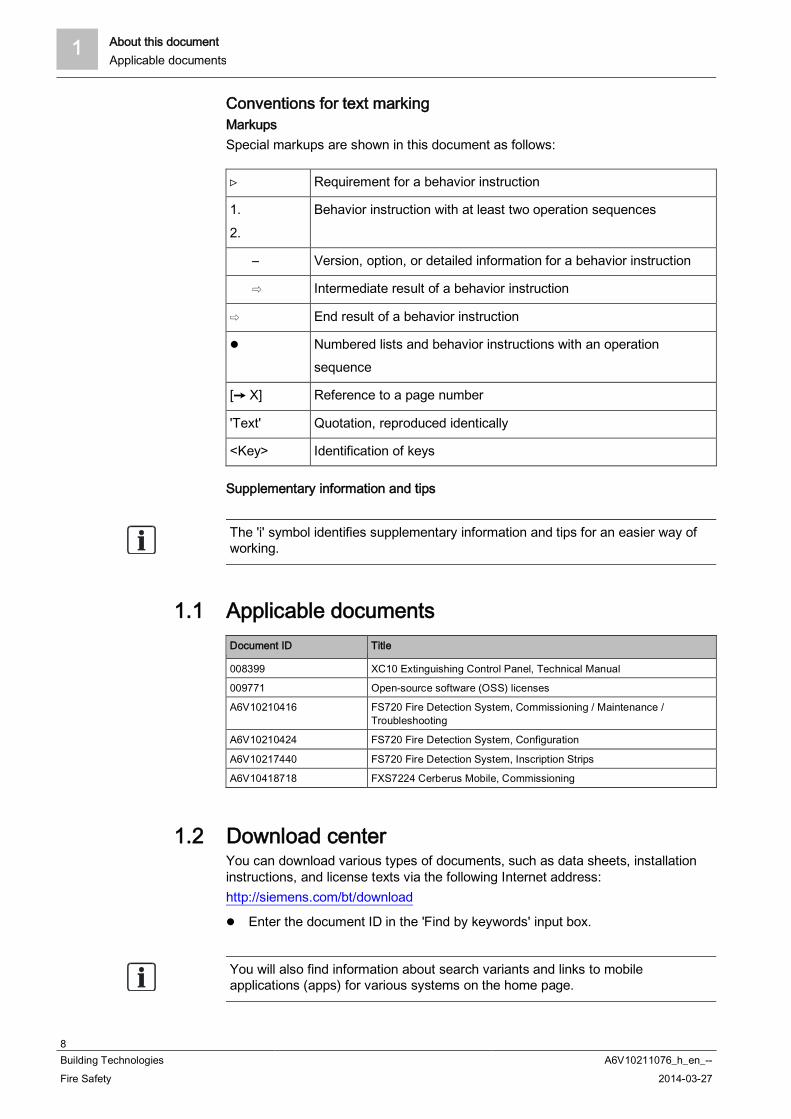
1.1 Applicable documentsDocument ID Title
008399 XC10 Extinguishing Control Panel, Technical Manual
009771 Open-source software (OSS) licenses
A6V10210416 FS720 Fire Detection System, Commissioning / Maintenance /Troubleshooting
A6V10210424 FS720 Fire Detection System, Configuration
A6V10217440 FS720 Fire Detection System, Inscription Strips
A6V10418718 FXS7224 Cerberus Mobile, Commissioning
1.2 Download centerYou can download various types of documents, such as data sheets, installationinstructions, and license texts via the following Internet address:http://siemens.com/bt/download
Enter the document ID in the 'Find by keywords' input box.
You will also find information about search variants and links to mobileapplications (apps) for various systems on the home page.

About this document 1Technical terms
9Building Technologies A6V10211076_h_en_--Fire Safety 2014-03-27
1.3 Technical termsYou will find technical terms and their explanation in the chapter 'Glossary'.
See also Glossary [ 154]
1.4 History of changesThe reference document's version applies to all languages into which the referencedocument is translated.
The first edition of a language version or a country variant may, for example, beversion 'd' instead of 'a' if the reference document is already this version.
The table below shows this document's history of changes:
Version Edition date Brief description
h 2014-02-10 Chapters 'Commands with required access levels' and 'LEDs' updated
g 2013-11-14 Edition for IP5Change to date format according to ISO 8601New:PIN administrationCerberus MobileCerberus Mobile operation modesSpecifying the operation mode for Cerberus MobileEnabling a smartphoneRemoving a smartphonePolling the switching-off timeExpiry reminder for temporary switching-offPolling reports'Report' command groupRevised:'Temporary switching-off' for levels 'Zone' and 'Detector', 'Override for different settings' in'Temporary switching-off', information on 'Temporary switching-off' in 'Switching off adetector zone' and 'Switching off a detector', menu structure, information on license keys,operating Cerberus-Remote with a PC keyboard, country-specific pre-configuration for'Counter control', 'Commands with required access levels'
f 2012-10 Correction to 'Temporary switching-off' of a 'Zone'
e 2012-08 IP4 editionRevised: Polling the alarm counter, command group 'Information'Commands revised, Test chapter revised, 'Walk test' new, note concerning buzzer volumeaccording to EN 54-2 Para. 12.10.2
d 2010-07 Edition MP3.0 XS:History of changes redefined and standardized, GAP new, router station new, CAPremoved, commands revised, glossary revised, new chapter: "Change language"
c 2009-03 Commands revised
b 2008-10 Tamper alarm, new
a 2008-07 First edition
1 About this documentHow displays are represented in the document
10Building Technologies A6V10211076_h_en_--Fire Safety 2014-03-27
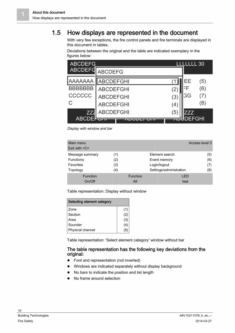
1.5 How displays are represented in the documentWith very few exceptions, the fire control panels and fire terminals are displayed inthis document in tables.Deviations between the original and the table are indicated exemplary in thefigures below:
Display with window and bar
Main menuExit with <C>
Access level 3
Message summaryFunctionsFavoritesTopology
(1)(2)(3)(4)
Element searchEvent memoryLogin/logoutSettings/administration
(5)(6)(7)(8)
FunctionOn/Off
FunctionAll
LEDtest
Table representation: Display without window
Selecting element category
ZoneSectionAreaSounderPhysical channel
(1)(2)(3)(4)(5)
Table representation: 'Select element category' window without bar
The table representation has the following key deviations from theoriginal:
Font and representation (not inverted) Windows are indicated separately without display background No bars to indicate the position and list length No frame around selection

Safety 2Safety instructions
11Building Technologies A6V10211076_h_en_--Fire Safety 2014-03-27
2 Safety
2.1 Safety instructionsThe safety notices must be observed in order to protect people and property.The safety notices in this document contain the following elements:
Symbol for danger Signal word Nature and origin of the danger Consequences if the danger occurs Measures or prohibitions for danger avoidance
Symbol for danger
This is the symbol for danger. It warns of risks of injury.
Follow all measures identified by this symbol to avoid injury or death.
Additional danger symbolsThese symbols indicate general dangers, the type of danger or possibleconsequences, measures and prohibitions, examples of which are shown in thefollowing table:
General danger Explosive atmosphere
Voltage/electric shock Laser light
Battery Heat
Signal wordThe signal word classifies the danger as defined in the following table:
Signal word Danger level
DANGER DANGER identifies a dangerous situation, which will result directly in death orserious injury if you do not avoid this situation.
WARNING WARNING identifies a dangerous situation, which may result in death or seriousinjury if you do not avoid this situation.
CAUTION CAUTION identifies a dangerous situation, which could result in slight tomoderately serious injury if you do not avoid this situation.
NOTICE NOTICE identifies possible damage to property that may result from non-observance.
2 SafetySafety regulations for the method of operation
12Building Technologies A6V10211076_h_en_--Fire Safety 2014-03-27
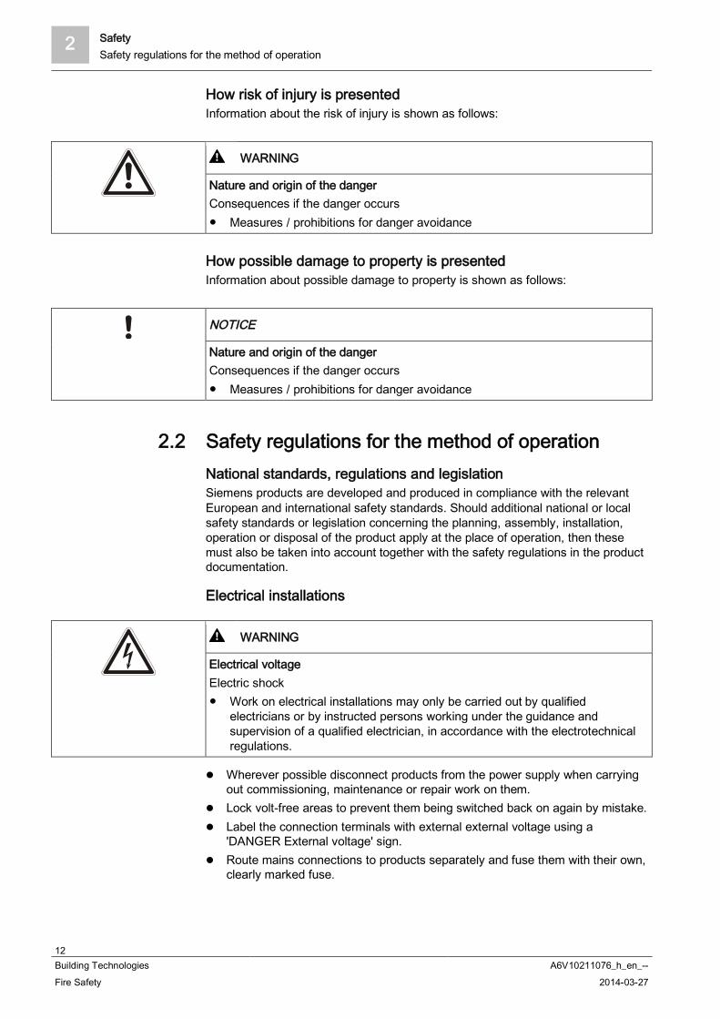
How risk of injury is presentedInformation about the risk of injury is shown as follows:
WARNING
Nature and origin of the dangerConsequences if the danger occurs
Measures / prohibitions for danger avoidance
How possible damage to property is presentedInformation about possible damage to property is shown as follows:
NOTICE
Nature and origin of the dangerConsequences if the danger occurs
Measures / prohibitions for danger avoidance
2.2 Safety regulations for the method of operationNational standards, regulations and legislationSiemens products are developed and produced in compliance with the relevantEuropean and international safety standards. Should additional national or localsafety standards or legislation concerning the planning, assembly, installation,operation or disposal of the product apply at the place of operation, then thesemust also be taken into account together with the safety regulations in the productdocumentation.
Electrical installations
WARNING
Electrical voltageElectric shock
Work on electrical installations may only be carried out by qualifiedelectricians or by instructed persons working under the guidance andsupervision of a qualified electrician, in accordance with the electrotechnicalregulations.
Wherever possible disconnect products from the power supply when carryingout commissioning, maintenance or repair work on them.
Lock volt-free areas to prevent them being switched back on again by mistake. Label the connection terminals with external external voltage using a
'DANGER External voltage' sign. Route mains connections to products separately and fuse them with their own,
clearly marked fuse.

Safety 2Safety regulations for the method of operation
13Building Technologies A6V10211076_h_en_--Fire Safety 2014-03-27
Fit an easily accessible disconnecting device in accordance with IEC 60950-1outside the installation.
Produce earthing as stated in local safety regulations.
Assembly, installation, commissioning and maintenance If you require tools such as a ladder, these must be safe and must be intended
for the work in hand. When starting the fire control panel ensure that unstable conditions cannot
arise. Ensure that all points listed in the 'Testing the product operability' section below
are observed. You may only set controls to normal function when the product operability has
been completely tested and the system has been handed over to the customer.
Testing the product operability Prevent the remote transmission from triggering erroneously. If testing building installations or activating devices from third-party companies,
you must collaborate with the people appointed. The activation of fire control installations for test purposes must not cause
injury to anyone or damage to the building installations. The followinginstructions must be observed:– Use the correct potential for activation; this is generally the potential of the
building installation.– Only check controls up to the interface (relay with blocking option).– Make sure that only the controls to be tested are activated.
Inform people before testing the alarm devices and allow for possible panicresponses.
Inform people about any noise or mist which may be produced. Before testing the remote transmission, inform the corresponding alarm and
fault signal receiving stations.
Modifications to the system design and the productsModifications to the system and to individual products may lead to faults,malfunctioning and safety risks. Written confirmation must be obtained fromSiemens and the corresponding safety bodies for modifications or additions.
Modules and spare parts Components and spare parts must comply with the technical specifications
defined by Siemens. Only use products specified or recommended bySiemens.
Only use fuses with the specified fuse characteristics. Wrong battery types and improper battery changing lead to a risk of explosion.
Only use the same battery type or an equivalent battery type recommended bySiemens.
Batteries must be disposed of in an environmentally friendly manner. Observenational guidelines and regulations.
Disregard of the safety regulationsBefore they are delivered, Siemens products are tested to ensure they functioncorrectly when used properly. Siemens disclaims all liability for damage or injuriescaused by the incorrect application of the instructions or the disregard of danger
2 SafetyStandards and directives complied with
14Building Technologies A6V10211076_h_en_--Fire Safety 2014-03-27
warnings contained in the documentation. This applies in particular to the followingdamage:
Personal injuries or damage to property caused by improper use and incorrectapplication
Personal injuries or damage to property caused by disregarding safetyinstructions in the documentation or on the product
Personal injury or damage to property caused by poor maintenance or lack ofmaintenance
2.3 Standards and directives complied withA list of the standards and directives complied with is available from your Siemenscontact.
2.4 Release NotesLimitations to the configuration or use of devices in a fire detection installation witha particular firmware version are possible.
WARNING
Limited or non-existent fire detectionPersonal injury and damage to property in the event of a fire.
Read the 'Release Notes' before you plan and/or configure a fire detectioninstallation.
Read the 'Release Notes' before you carry out a firmware update to a firedetection installation.
NOTICE
Incorrect planning and/or configurationImportant standards and specifications are not satisfied.Fire detection installation is not accepted for commissioning.Additional expense resulting from necessary new planning and/or configuration.
Read the 'Release Notes' before you plan and/or configure a fire detectioninstallation.
Read the 'Release Notes' before you carry out a firmware update to a firedetection installation.

PMI 3Release Notes
15Building Technologies A6V10211076_h_en_--Fire Safety 2014-03-27
3 PMIThe following figure shows the PMI of a station (fire control panel or fire terminal).
PMI Station
1 ALARM LEDs 8 System fault LED (yellow)2 Display 9 Operation LED (green)
3 Navigation buttons A More alarmsbutton
4 Keypad with Menu key, ok key and Cancel key S Softkeys 1–35 Area for fitting options X 'Silence buzzer', 'Acknowledge', 'Reset', 'Alarm delay
off', 'Premises manned' standard buttons
6 Key switch (optional) k1 Configurable buttons with LEDs (can be configuredindependently)
7 'Alarm device button k2 Configurable LEDs
You can use inscription strips to inscribe the PMI. You will find a template for thisin document A6V10217440.

3 PMIButtons on the PMI
16Building Technologies A6V10211076_h_en_--Fire Safety 2014-03-27
3.1 Buttons on the PMIThe figure below shows the PMI with the standard buttons and the button 'Morealarms':
PMI of the station
1 'Silence buzzer' 6 'Alarm device' button
2 'Acknowledge' 7 'More alarms' button
3 'Reset' 8 Configurable standard button 14 'Alarm delay off' b Configurable standard button 2
5 'Premises manned' S Softkeys 1-3
3.1.1 Standard keysWith the standard buttons, functions can be performed at the push of a button.
<Silence buzzer>Switches the 'Station' buzzer off.
<Acknowledge> Acknowledges all events that can be acknowledged. Confirms presence ('AVC', 'IC') Switches the buzzer off
<Reset>Resets all events that can be reset (password required).
<Alarm delay off> Switches off the alarm delay for all events. In the event of an alarm, the remote transmission or global alarming is
activated immediately.

PMI 3Buttons on the PMI
17Building Technologies A6V10211076_h_en_--Fire Safety 2014-03-27
<Premises manned> Switches between 'Manned operation' and 'Unmanned operation' operation
modes (password required). Opens the event list in case of a "mixed" condition (i.e., visibility on several
'Areas' with different 'Manned operation' and 'Unmanned operation' settings)
<Alarm device>Deactivates the alarm devices in the event of alarm (password required).
Configurable buttons
The two buttons a and b in the figure above are configurable standard buttons.
You can, for example, configure these two buttons with the following functions: 'Poll RT counter' 'Non-MCP zones OFF'
3.1.2 Other alarmsPressing the 'More alarms' button opens the 'ALARMS' event list.If the 'ALARMS' event list is already open, <More alarms> assumes the function ofthe button < >, changing to the next alarm event upon activation.
3.1.3 SoftkeysThe figure below shows the part of the PMI including the softkeys.
Button for softkey function
Softkeys are buttons which you can use to carry out functions and which aredisplayed in the three fields of the softkey line on the display. These three blackfields contain the names of the functions in white font.The functions of the softkeys change dynamically depending on the situation andthe contents of the display.Always the most important functions are assigned to the softkeys 1 and 2.
When the user navigates through the topology, the softkey allocation does notchange depending on the context; the assignment remains fixed. If a softkeyfunction cannot be executed at a point in the topology, the inscription in the field ishidden.
3 PMIButtons on the PMI
18Building Technologies A6V10211076_h_en_--Fire Safety 2014-03-27
The table below lists an exemplary softkey assignment.
Softkey / Option Function
'Show intervention text' 1 Shows the intervention text of the selected event.
'Jump back' Displays the list the selected event has been taken from. Back from the viewIntervention text or Details.
'Execute command' Opens the 'Select command' window.
'More options' Opens the 'Select option' window.
'Show details' 2 Shows details of the selected event or element.
'Lower level' Changes to the next lower hierarchy level.
'Upper level ' Changes to the next higher hierarchy level.
'Jump to begin' / 'Jump to end' Within a list, jumps to the top or end of the list
'Show topology ' 3 Jumps to the selected element in the topology.
'Show active detectors' Shows a list of all active detectors, corresponding to an event list.
1 Softkey / Option is only displayed when intervention text is available at this point2 Softkey / Option available only in 'Access level 3'3 Softkey / Option available only as of 'Access level 2.1'
See also Normal view [ 22]
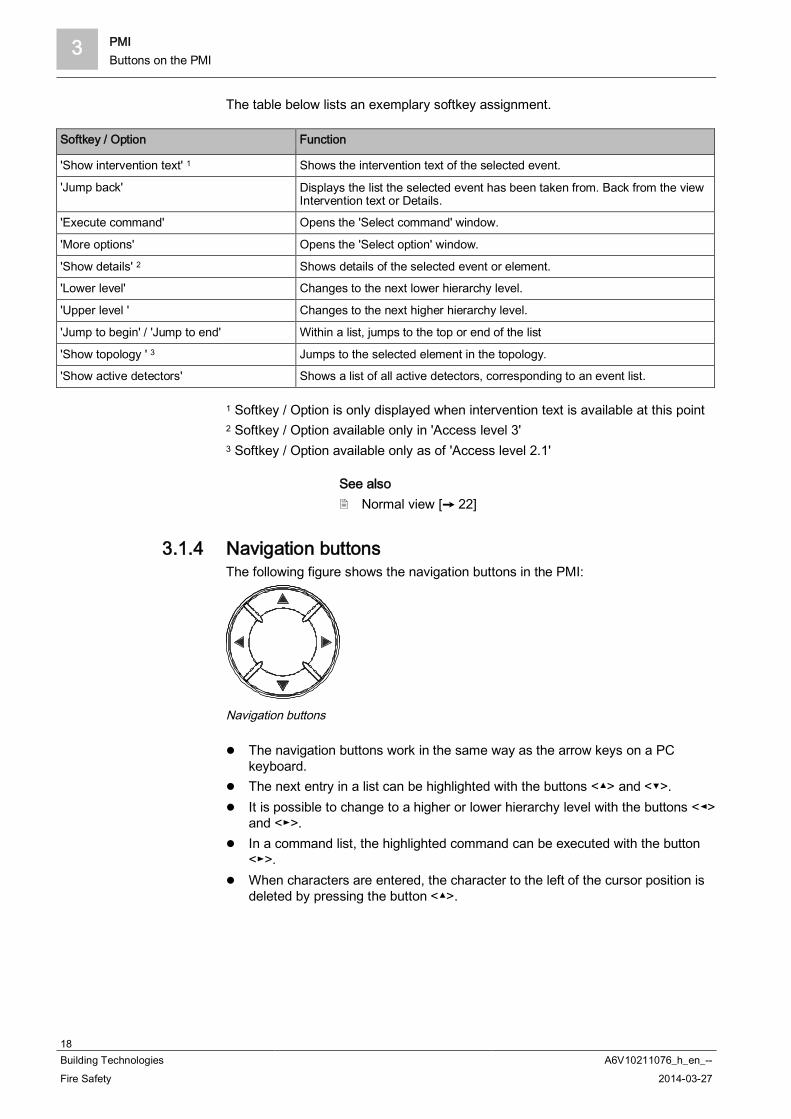
3.1.4 Navigation buttonsThe following figure shows the navigation buttons in the PMI:
Navigation buttons
The navigation buttons work in the same way as the arrow keys on a PCkeyboard.
The next entry in a list can be highlighted with the buttons < > and < >. It is possible to change to a higher or lower hierarchy level with the buttons < >
and < >. In a command list, the highlighted command can be executed with the button< >.
When characters are entered, the character to the left of the cursor position isdeleted by pressing the button < >.
PMI 3Buttons on the PMI
19Building Technologies A6V10211076_h_en_--Fire Safety 2014-03-27
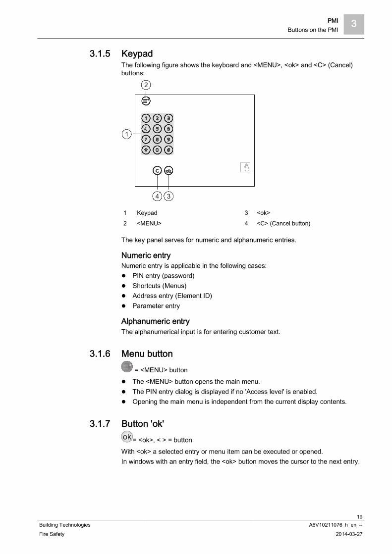
3.1.5 KeypadThe following figure shows the keyboard and <MENU>, <ok> and <C> (Cancel)buttons:
1
2
34
1 Keypad 3 <ok>
2 <MENU> 4 <C> (Cancel button)
The key panel serves for numeric and alphanumeric entries.
Numeric entryNumeric entry is applicable in the following cases:
PIN entry (password) Shortcuts (Menus) Address entry (Element ID) Parameter entry
Alphanumeric entryThe alphanumerical input is for entering customer text.
3.1.6 Menu button = <MENU> button
The <MENU> button opens the main menu. The PIN entry dialog is displayed if no 'Access level' is enabled. Opening the main menu is independent from the current display contents.
3.1.7 Button 'ok'ok = <ok>, < > = buttonWith <ok> a selected entry or menu item can be executed or opened.In windows with an entry field, the <ok> button moves the cursor to the next entry.
3 PMIEVAC NL
20Building Technologies A6V10211076_h_en_--Fire Safety 2014-03-27
3.1.8 Button 'C'C = Cancel button <C>
With <C>, any operation sequence can be cancelled and any open list or windowcan be closed.
3.2 EVAC NL
Zoemeruit
IN/UIT
BedrijfUitgeschakeldStoring
Ontruimingsalarm
Zone 1
Zone 2
Zone 3
Zone 4
TotaalAlarm
4
3
2
5
1
6
a cb
d
g
f
e
7
Selecteer
Start
Stop 2x
i
Zone 5
Zone 6
Zone 7
Zone 8
Zone 9
Zone 10
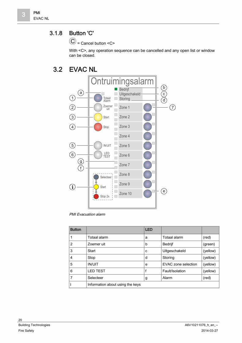
PMI Evacuation alarm
Button LED
1 Totaal alarm a Totaal alarm (red)
2 Zoemer uit b Bedrijf (green)
3 Start c Uitgeschakeld (yellow)
4 Stop d Storing (yellow)
5 IN/UIT e EVAC zone selection (yellow)
6 LED TEST f Fault/Isolation (yellow)
7 Selecteer g Alarm (red)
i Information about using the keys

PMI 3Display
21Building Technologies A6V10211076_h_en_--Fire Safety 2014-03-27
3.2.1 Functions on the EVAC PMIButton Function
1 Totaal alarm Pressing the button selects all EVAC zones.
2 Zoemer uit Silences the buzzer of the EVAC PMI.
3 Start Activates selected EVAC zones.
4 Stop Deactivates selected EVAC zones.
5 IN/UIT Switches selected EVAC zones on or off.
6 LED TEST Activates the LED test on the EVAC PMI.
7 Selecteer Selects an EVAC zone for the issuing ofadditional commands (Start, Stop, ON/OFF)
LED Function
a Totaal alarm Indicates that Overall Alarm has been activated.
b Bedrijf Active as long as power supply is available.
c Uitgeschakeld Active when at minimum one EVAC zone isswitched off.
d Storing Active when at least one fault is present in anEVAC zone.
Active (flashing) when the connection to thefire control panel is faulty
e EVAC zone selection Active when the zone has been selected.
f Fault/Isolation Active when an EVAC zone has been switchedoff or a fault is present.
g Alarm Active when all EVAC zones are activated.
3.3 DisplayThe display of the station has two displaying variants:
Display without window– Normal view– Expanded visibility– 'Fire Brig. view'
Display with window for following representations– Lists– Input fields– Command responses
3 PMIDisplay
22Building Technologies A6V10211076_h_en_--Fire Safety 2014-03-27
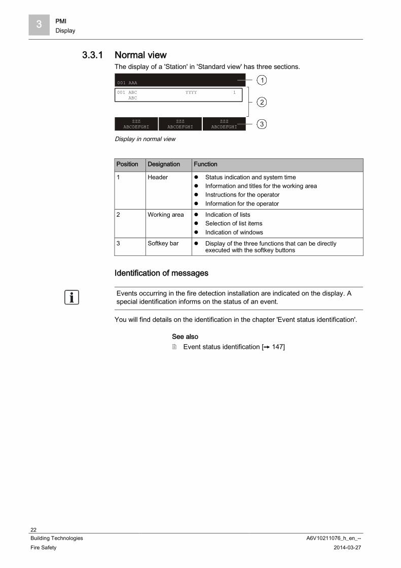
3.3.1 Normal viewThe display of a 'Station' in 'Standard view' has three sections.
001 AAA
001 ABC ABC
ZZZABCDEFGHI
ZZZABCDEFGHI
ZZZABCDEFGHI
YYYY 1
1
2
3
Display in normal view
Position Designation Function
1 Header Status indication and system time Information and titles for the working area Instructions for the operator Information for the operator
2 Working area Indication of lists Selection of list items Indication of windows
3 Softkey bar Display of the three functions that can be directlyexecuted with the softkey buttons
Identification of messages
Events occurring in the fire detection installation are indicated on the display. Aspecial identification informs on the status of an event.
You will find details on the identification in the chapter 'Event status identification'.
See also Event status identification [ 147]

PMI 3Display
23Building Technologies A6V10211076_h_en_--Fire Safety 2014-03-27
3.3.2 Extended viewThe display of events, elements, etc., comprises two lines in 'Standard view'.The extended view shows a 4-line depiction of the selection. Additional informationsuch as e.g. additional customer texts can be displayed this way.In the extended view there is a frame around four lines.
Display with extended view
With the <Switch to Extended view> and the <Switch to Standard view> softkeys,you can switch from 'Standard view' to 'Extended view' and vice versa.Alternatively, the navigation buttons < > and < > can be used to switch over.
3.3.3 Fire department viewFor 'ALARM' events, the 'Fire Brigade message view' can be configured in theEngineering tool.An 'ALARM' event is displayed in double font size in the 'Fire Brigade messageview'.
Display with 'Fire Brig. view'
3.3.4 Display with window and listThe display with window and list is for the selection of a list item, whichcorresponds to a submenu.the figure below shows the display with an exemplary list:
Example of the display with window and list
3 PMIDisplay
24Building Technologies A6V10211076_h_en_--Fire Safety 2014-03-27
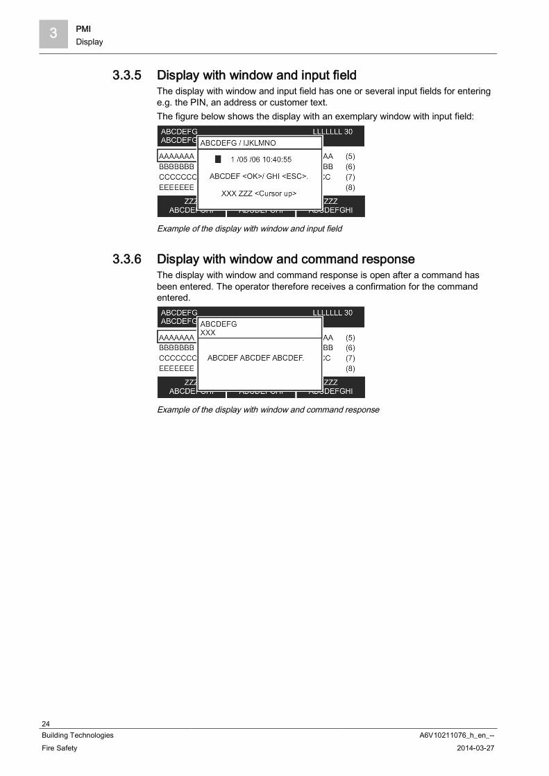
3.3.5 Display with window and input fieldThe display with window and input field has one or several input fields for enteringe.g. the PIN, an address or customer text.The figure below shows the display with an exemplary window with input field:
Example of the display with window and input field
3.3.6 Display with window and command responseThe display with window and command response is open after a command hasbeen entered. The operator therefore receives a confirmation for the commandentered.
Example of the display with window and command response
PMI 3LEDs
25Building Technologies A6V10211076_h_en_--Fire Safety 2014-03-27
3.4 LEDsThe LEDs on the Person Machine Interface signal 'Events' and conditions. Inaddition, the LEDs support the operator's orientation. The LEDs can light up in red,yellow, or green. The LEDs can be configured according to customer-specificrequirements.The LED colors can, for example, signal the following information:
Red ALARM Activations, e.g. remote transmission, alarm devices,
control function
Yellow Fault Isolation Deactivation, e.g. remote transmission, alarm devices,
control function
Green System is in operation
Additional information on the conditions of the LEDs (steady on, steady off orflashing) can be found in the relevant chapter.
3.5 Key switch (optional)You can use the key switch to release an access level. The accessible access levelis configurable.The key switch has 2 positions:
On (horizontal position) Off (vertical position)
See also Logout timeout [ 100]
3 PMIMenu structure
26Building Technologies A6V10211076_h_en_--Fire Safety 2014-03-27
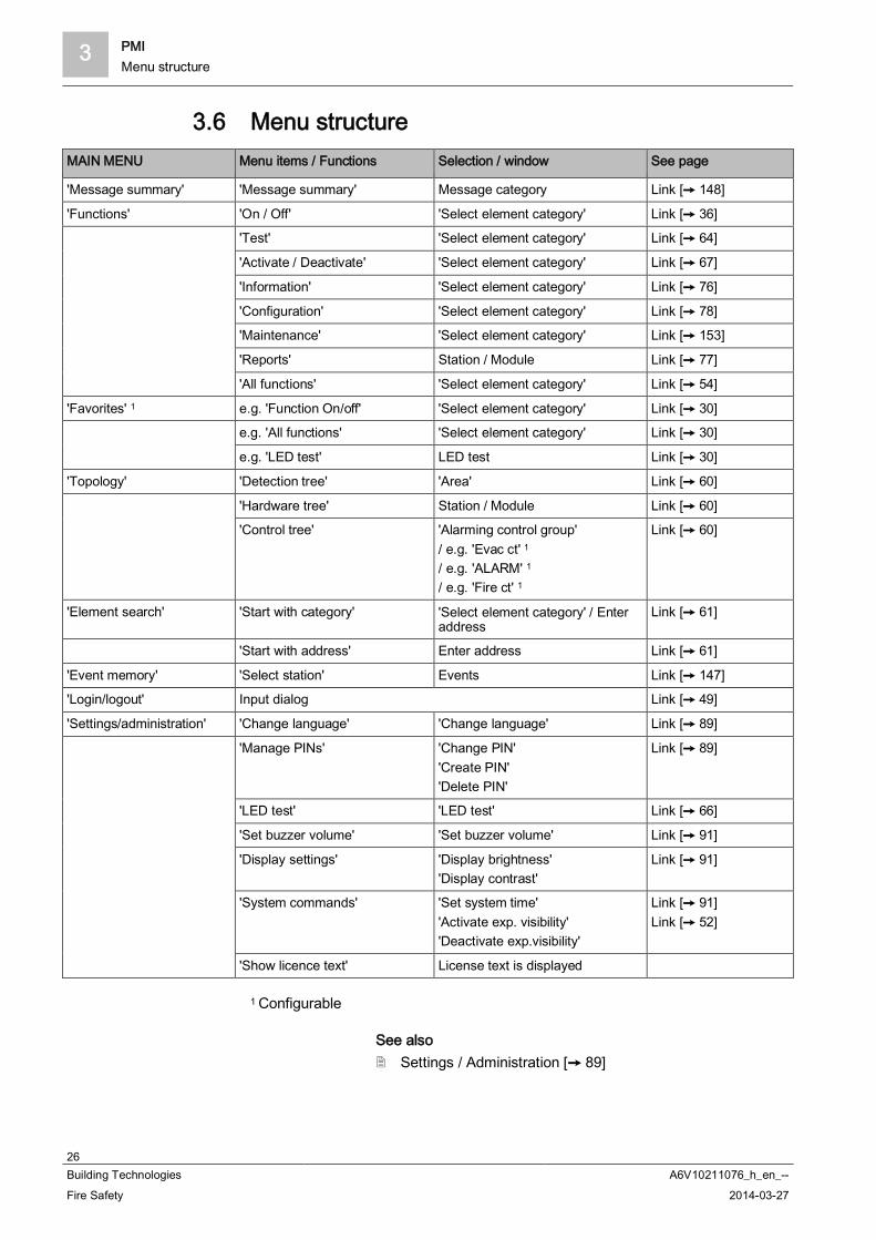
3.6 Menu structureMAIN MENU Menu items / Functions Selection / window See page
'Message summary' 'Message summary' Message category Link [ 148]
'Functions' 'On / Off' 'Select element category' Link [ 36]
'Test' 'Select element category' Link [ 64]
'Activate / Deactivate' 'Select element category' Link [ 67]
'Information' 'Select element category' Link [ 76]
'Configuration' 'Select element category' Link [ 78]
'Maintenance' 'Select element category' Link [ 153]
'Reports' Station / Module Link [ 77]
'All functions' 'Select element category' Link [ 54]
'Favorites' 1 e.g. 'Function On/off' 'Select element category' Link [ 30]
e.g. 'All functions' 'Select element category' Link [ 30]
e.g. 'LED test' LED test Link [ 30]
'Topology' 'Detection tree' 'Area' Link [ 60]
'Hardware tree' Station / Module Link [ 60]
'Control tree' 'Alarming control group'/ e.g. 'Evac ct' 1
/ e.g. 'ALARM' 1
/ e.g. 'Fire ct' 1
Link [ 60]
'Element search' 'Start with category' 'Select element category' / Enteraddress
Link [ 61]
'Start with address' Enter address Link [ 61]
'Event memory' 'Select station' Events Link [ 147]
'Login/logout' Input dialog Link [ 49]
'Settings/administration' 'Change language' 'Change language' Link [ 89]
'Manage PINs' 'Change PIN''Create PIN''Delete PIN'
Link [ 89]
'LED test' 'LED test' Link [ 66]
'Set buzzer volume' 'Set buzzer volume' Link [ 91]
'Display settings' 'Display brightness''Display contrast'
Link [ 91]
'System commands' 'Set system time''Activate exp. visibility''Deactivate exp.visibility'
Link [ 91]Link [ 52]
'Show licence text' License text is displayed
1 Configurable
See also Settings / Administration [ 89]

PMI 3Cerberus Remote
27Building Technologies A6V10211076_h_en_--Fire Safety 2014-03-27
3.7 Cerberus Remote
Cerberus-Remote is software for the PC which can be used to display the PersonMachine Interface of a 'Station' on the PC. For example, it can be used to accessthe system for maintenance purposes.Depending on the operation mode, Cerberus-Remote can either be used fordisplay purposes or for display and operation purposes.The link between Cerberus-Remote and a 'Station' can be structured as follows:
Local connection via any 'Station' in the system Connection via the Global Access Point (GAP)
Cerberus-Remote is an integrated part of Cerberus-Engineering-Tool but may alsobe installed on a PC as a stand-alone application 'FX7220'.You will need an installed license key and appropriate authorization for the 'Station'in order to use Cerberus-Remote. The license key must support the Cerberus-Remote function. The license key need only be installed in the 'Station' that has thePerson Machine Interface that is to be displayed in Cerberus-Remote.
You will find more information about license keys in document A6V10210362.See chapter 'Applicable documents'.
The connection to a 'Station' with a license key is also possible via a 'Station'without a license key.
Cerberus-Remote has the same visibility as the connected 'Station'. You can useCerberus-Remote in a system with networked 'Stations' to gain global visibility.Just one license key is needed for this per network if the license key is installed ina 'Station' with global visibility.
The connection with a 'Station' is shown by the Person Machine Interface(display, LEDs, keys) transmitted.The 'Cerberus-Remote access' operation mode is indicated by a red framearound the Person Machine Interface.An enable granted for Cerberus-Remote is retained when a 'Station' restarted.
See also Cerberus Remote operating modes [ 31] Enabling / Disabling Cerberus Remote [ 82] Operating Cerberus Remote [ 85]

3 PMICerberus Mobile
28Building Technologies A6V10211076_h_en_--Fire Safety 2014-03-27
3.8 Cerberus Mobile'Cerberus Mobile' is an app for smartphones. Depending on the operation mode,Cerberus Mobile can be used either to display or to display and operate 'Station'.For example it can be used to access the fire detection system for maintenancepurposes.
You will find more information about 'Cerberus Mobile' in documentA6V10418718. See chapter 'Applicable documents'.
You will need an installed license key and appropriate authorization for the 'Station'in order to use Cerberus Mobile. The license key must support the 'CerberusMobile' function.
You will find more information about license keys in document A6V10210362.See chapter 'Applicable documents'.
Operation functions 4Selection and opening / execution
29Building Technologies A6V10211076_h_en_--Fire Safety 2014-03-27
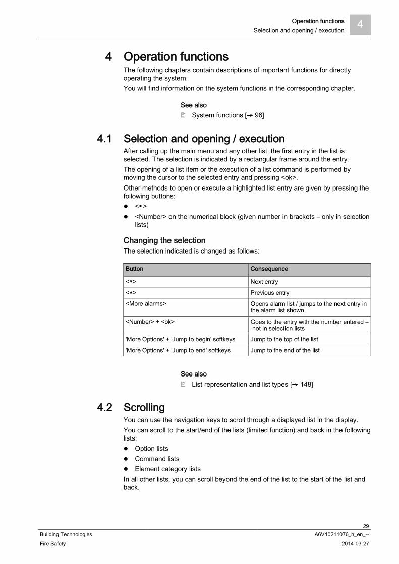
4 Operation functionsThe following chapters contain descriptions of important functions for directlyoperating the system.You will find information on the system functions in the corresponding chapter.
See also System functions [ 96]
4.1 Selection and opening / executionAfter calling up the main menu and any other list, the first entry in the list isselected. The selection is indicated by a rectangular frame around the entry.The opening of a list item or the execution of a list command is performed bymoving the cursor to the selected entry and pressing <ok>.Other methods to open or execute a highlighted list entry are given by pressing thefollowing buttons:
< > <Number> on the numerical block (given number in brackets – only in selection
lists)
Changing the selectionThe selection indicated is changed as follows:
Button Consequence
< > Next entry
< > Previous entry
<More alarms> Opens alarm list / jumps to the next entry inthe alarm list shown
<Number> + <ok> Goes to the entry with the number entered – not in selection lists
'More Options' + 'Jump to begin' softkeys Jump to the top of the list
'More Options' + 'Jump to end' softkeys Jump to the end of the list
See also List representation and list types [ 148]
4.2 ScrollingYou can use the navigation keys to scroll through a displayed list in the display.You can scroll to the start/end of the lists (limited function) and back in the followinglists:
Option lists Command lists Element category lists
In all other lists, you can scroll beyond the end of the list to the start of the list andback.

4 Operation functionsIndication of the position and length of the list
30Building Technologies A6V10211076_h_en_--Fire Safety 2014-03-27
4.3 Indication of the position and length of the listThere is a vertical bar along the side of a list when the list is longer than can beindicated on the display.The black part of the bar shows the position and size of the part of the list you cansee in relation to the entire list.Examples for the representation in different lists:
1 Bar in normal view with list 2 Bar in window with list
See also Event status identification [ 147]
4.4 ShortcutA shortcut serves for the direct execution of an entry in a selection list by pressinga numeric key.In a command list, for example, you can execute a command directly by enteringthe corresponding number.The numbers for the shortcut are shown in the list entry line, on the right and inbrackets.
4.5 FavoritesYou can use favorites to execute several operation sequences or one operatingsequence in an operation sequence.A maximum of 8 favorites are configured and you can select them from the favoritelist in the 'Favorites' main menu item.

Operation functions 4Entry of numbers and letters
31Building Technologies A6V10211076_h_en_--Fire Safety 2014-03-27
4.6 Entry of numbers and lettersYou can use the keyboard to enter numbers and letters in input dialogs.
Numeric entry The number of underscores corresponds to the number of possible positions
for the entry. The overwrite mode is set by default; there is no insert mode. Horizontal navigation within the input field is possible with the keys < > and< >.
Use < > to delete the character to the left of the cursor position. Use <ok> to save the entered value and exit the input field.
– When there are several input fields in the window, the cursor jumps to thenext field by pressing <ok>.
– If the cursor position is in the last or only input field, close the input dialogby pressing <ok>.
Use <C> to cancel the input and close the dialog without saving.
Alphanumeric entry Alphanumeric entries are only possible in particular input fields, e.g. for
customer text. Letters are entered in the same way as letters on telephones. You can select
the corresponding letter by pressing a key several times. Switching between lower and upper case letters is possible with the key <*>
and only applies for the next character.
In input fields with more than one line, you cannot change back to a line abovethe cursor position.
4.7 Cerberus Remote operating modesCerberus-Remote has the following operation modes:
'Limited access (view only)' 'Full access (view/operation)'
For both operation modes, SintesoView must be enabled on the 'Station'. Inaddition, a license key must be installed. The license key must support theCerberus-Remote function.
You will find more information about license keys in document A6V10210362.See chapter 'Applicable documents'.
'Limited access (view only)'In this operation mode Cerberus-Remote indicates the same as the 'Station'connected to it, but you cannot operate the linked 'Station'.The figure in Cerberus-Remote indicates the display with all indicated texts, allLEDs in their current state and all buttons.

4 Operation functionsCerberus Mobile operation modes
32Building Technologies A6V10211076_h_en_--Fire Safety 2014-03-27
'Full access (view/operation)'In this operation mode, the connected 'Station' is visualized as in the 'Limitedaccess (view only)' operation mode. Additionally, the 'Station' can be operated withCerberus-Remote, while normal operation on the 'Station' is blocked, but can bereactivated.
As operation on a 'Station' must have priority, this restriction (blocking) on the'Station' can be cancelled at any time.Each time an attempt is made to operate on the 'Station', a dialog is indicated withthe option to abort the connection with Cerberus-Remote.
The LED test also tests the display. However, the LEDs are not displayed in'Cerberus-Remote'.
See also Enabling / Disabling Cerberus Remote [ 82]
4.8 Cerberus Mobile operation modesTwo operation modes can be specified for 'Cerberus Mobile' at the 'Station':
'Limited access (view only)' 'Full access (view/operation)'
The operation mode must be configured at the 'Station'.
'Limited access (view only)'In this operation mode, 'Cerberus Mobile' displays 'Station' events. The eventsdisplayed are determined by the configured 'Visibility' for 'Cerberus Mobile'. In thisoperation mode, you cannot operate the 'Station' with 'Cerberus Mobile'.
'Full access (view/operation)'In this operation mode, you can operate the 'Station' with the controls in 'CerberusMobile'. The events displayed are determined by the configured 'Visibility' for'Cerberus Mobile'.
Operation 5ALARM Procedure
33Building Technologies A6V10211076_h_en_--Fire Safety 2014-03-27
5 OperationIn this part of the document you will find brief descriptions and detailed operationsequences for important functions of the fire detection installation. In addition, youcan find your preferred procedures in the representation of exemplary operationsequences.
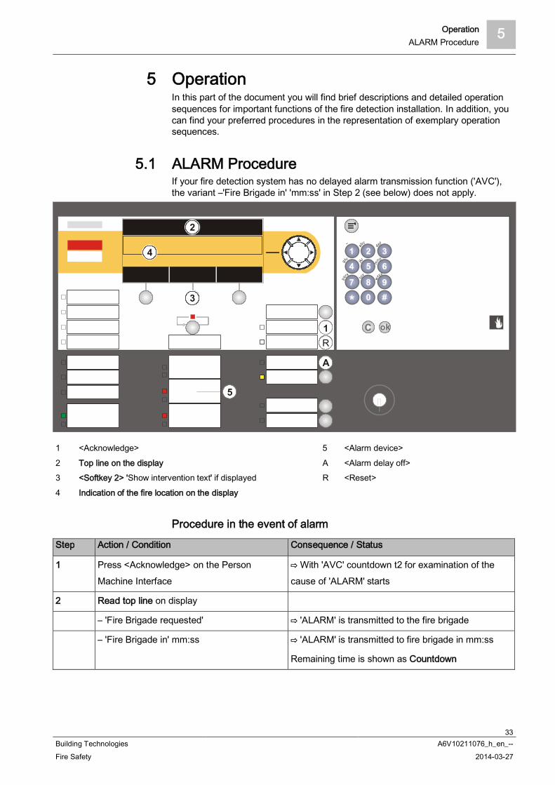
5.1 ALARM ProcedureIf your fire detection system has no delayed alarm transmission function ('AVC'),the variant –'Fire Brigade in' 'mm:ss' in Step 2 (see below) does not apply.
1 <Acknowledge> 5 <Alarm device>
2 Top line on the display A <Alarm delay off>3 <Softkey 2> 'Show intervention text' if displayed R <Reset>
4 Indication of the fire location on the display
Procedure in the event of alarm
Step Action / Condition Consequence / Status
1 Press <Acknowledge> on the PersonMachine Interface
With 'AVC' countdown t2 for examination of thecause of 'ALARM' starts
2 Read top line on display
– 'Fire Brigade requested' 'ALARM' is transmitted to the fire brigade
– 'Fire Brigade in' mm:ss 'ALARM' is transmitted to fire brigade in mm:ss
Remaining time is shown as Countdown
5 OperationALARM Procedure
34Building Technologies A6V10211076_h_en_--Fire Safety 2014-03-27
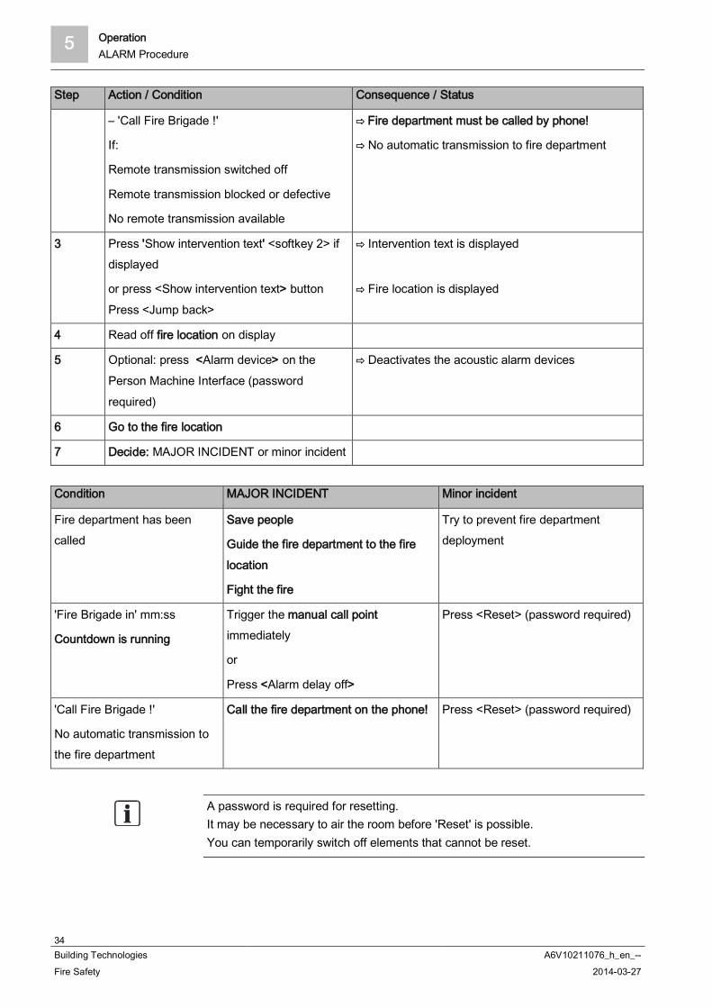
Step Action / Condition Consequence / Status
– 'Call Fire Brigade !'
If:
Remote transmission switched off
Remote transmission blocked or defective
No remote transmission available
Fire department must be called by phone!
No automatic transmission to fire department
3 Press 'Show intervention text' <softkey 2> ifdisplayed
or press <Show intervention text> buttonPress <Jump back>
Intervention text is displayed
Fire location is displayed
4 Read off fire location on display
5 Optional: press <Alarm device> on thePerson Machine Interface (passwordrequired)
Deactivates the acoustic alarm devices
6 Go to the fire location
7 Decide: MAJOR INCIDENT or minor incident
Condition MAJOR INCIDENT Minor incident
Fire department has beencalled
Save people
Guide the fire department to the firelocation
Fight the fire
Try to prevent fire departmentdeployment
'Fire Brigade in' mm:ss
Countdown is running
Trigger the manual call pointimmediately
or
Press <Alarm delay off>
Press <Reset> (password required)
'Call Fire Brigade !'
No automatic transmission tothe fire department
Call the fire department on the phone! Press <Reset> (password required)
A password is required for resetting.It may be necessary to air the room before 'Reset' is possible.You can temporarily switch off elements that cannot be reset.

Operation 5Procedure in case of Fault
35Building Technologies A6V10211076_h_en_--Fire Safety 2014-03-27
5.2 Procedure in case of FaultStep Action
1 Press <Silence buzzer> on the Person Machine Interface
2 Read message/fault location on the display
3 Go to the fault location
4 Eliminate the cause of the fault
A list of possible 'Faults' and how they are eliminated can be found in the chapter'Faults / Troubleshooting'. If you cannot eliminate 'Fault', please contact yourservice provider.
'Fault' and 'Intervention Concept' (IC)On consideration of 'Intervention Concept', events of the 'Fault' category can beassigned their own sequence. This sequence may be configured differently anddepends on the 'Manned operation' / 'Unmanned operation' operation mode.An exemplary process following 'Fault', taking in account 'Intervention Concept', isgraphically shown in the 'Intervention Concept (IC) chapter and is outlined below:
'Fault' has occurred The remote transmission for 'Faults' is activated in 'Unmanned operation'
operation mode. The remote transmission for 'Faults' is activated in 'Manned operation'
operation mode unless 'Fault' is acknowledged within the delay t1.
Acknowledging 'Fault'1. Press <Acknowledge> before the expiry of t1.
2. Read the 'Fault'location on the display.
3. Go to the 'Fault' location.
4. Rectify 'Fault'.
See also Intervention concept (IC) [ 141] Faults / Troubleshooting [ 152]

5 OperationSwitching off / Switching on
36Building Technologies A6V10211076_h_en_--Fire Safety 2014-03-27
5.3 Switching off / Switching on To avoid false alarms or fault messages, you can switch off parts of a 'Site' incertain situations, e.g. for the purpose of maintenance work.When a part of a system is switched off, the 'Isolation' LED is on. The situations in which part of a 'Site' should be switched off, depends on thedetectors used as well as on possible deceptive phenomena such as smoke, dust,heat or vapour.
WARNING
System parts that have been switched off make it impossible to acquire andprocess alarms or faults!Fire may spread unhindered.
Deploy staff to monitor the deactivated area.You must switch deactivated parts of the 'Site' back on as soon as possible.
If a deactivated 'Zone' is the only 'Zone' in a 'Section', the 'Section' is alsoindicated as deactivated.
Examples of switching off/on are provided in the following chapters.
5.3.1 Switching a detector zone off / on
WARNING
System parts that have been switched off make it impossible to acquire andprocess alarms or faults!Fire may spread unhindered.
Deploy staff to monitor the deactivated area.You must switch deactivated parts of the 'Site' back on as soon as possible.
If a deactivated 'Zone' is the only 'Zone' in a 'Section', the 'Section' is alsoindicated as deactivated.
You will find information on temporarily switching off detector zones in chapter'Temporary switching-off [ 42]'.
Operation 5Switching off / Switching on
37Building Technologies A6V10211076_h_en_--Fire Safety 2014-03-27
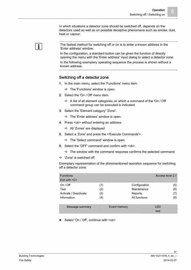
In which situations a detector zone should be switched off, depends on thedetectors used as well as on possible deceptive phenomena such as smoke, dust,heat or vapour.
The fastest method for switching off or on is to enter a known address in the'Enter address' window.In the configuration, a standard button can be given the function of directlyopening the menu with the 'Enter address' input dialog to select a detector zone.In the following exemplary operating sequence the process is shown without aknown address.
Switching off a detector zone1. In the main menu, select the 'Functions' menu item.
The 'Functions' window is open.
2. Select the 'On / Off' menu item.
A list of all element categories on which a command of the 'On / Off'command group can be executed is indicated.
3. Select the 'Element category' 'Zone'.
The 'Enter address' window is open.
4. Press <ok> without entering an address.
All 'Zones' are displayed
5. Select a 'Zone' and press the <'Execute Commands'>.
The 'Select command' window is open.
6. Select the 'OFF' command and confirm with <ok>.
The window with the command response confirms the selected command.
'Zone' is switched off.
Exemplary representation of the aforementioned operation sequence for switchingoff a detector zone:
FunctionsExit with <C>
Access level 2.1
On / OffTestActivate / DeactivateInformation
(1)(2)(3)(4)
ConfigurationMaintenanceReportsAll functions
(5)(6)(7)(8)
Message summary Event memory LEDtest
Select 'On / Off', continue with <ok>
5 OperationSwitching off / Switching on
38Building Technologies A6V10211076_h_en_--Fire Safety 2014-03-27
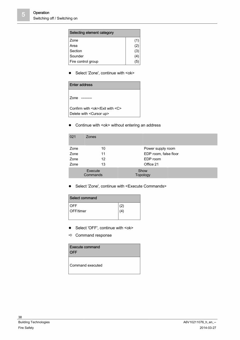
Selecting element category
ZoneAreaSectionSounderFire control group
(1)(2)(3)(4)(5)
Select 'Zone', continue with <ok>
Enter address
Zone ---------
Confirm with <ok>/Exit with <C>Delete with <Cursor up>
Continue with <ok> without entering an address
021 Zones
ZoneZoneZoneZone
10111213
Power supply roomEDP room, false floorEDP roomOffice 21
ExecuteCommands
ShowTopology
Select 'Zone', continue with <Execute Commands>
Select command
OFFOFF/timer
(2)(4)
Select 'OFF', continue with <ok>
Command response
Execute commandOFF
Command executed

Operation 5Switching off / Switching on
39Building Technologies A6V10211076_h_en_--Fire Safety 2014-03-27
Switching a detector zone onProceed as with switching off, but select the 'ON' command.Alternatively, with 'Message summary' from the main menu and 'Event category''Isolations', you can also select the corresponding 'Zone' and reactivate with the<softkey> 'Execute Commands'.
See also Execute commands – object-oriented [ 56]
5.3.2 Switching a detector off / on
WARNING
System parts that have been switched off make it impossible to acquire andprocess alarms or faults!Fire may spread unhindered.
Deploy staff to monitor the deactivated area.You must switch deactivated parts of the 'Site' back on as soon as possible.
If an isolated 'Detector' is the only 'Detector' in a 'Zone' or if all 'Detectors' in a'Zone' are isolated, the 'Zone' is displayed as isolated.
You will find information on temporarily switching off detectors in chapter'Temporary switching-off [ 42]'.
Switching off the 'Detector'1. In the main menu, select the 'Topology' menu item.
The 'Topology' window is open.
2. Select 'Detection tree' and click <ok>.
The elements of 'Detection tree' are displayed.
3. Select the element 'Area 1'.
The elements of 'Area 1' are displayed.
4. Select 'Area 1' and press 'Lower level' <softkey 2>.
All 'Sections' in 'Area 1' are displayed.
5. Select 'Section 1' and press 'Lower level' <softkey 2>.
All 'Zones' in 'Section 1' are displayed.
6. Select 'Zone 1' and press 'Lower level' <softkey 2>.
All detectors of 'Zone 1' are displayed.
7. Select 'Detect. 1' and press 'More Options' <softkey 3>.
The 'Select option' window is open.
8. Select 'Execute commands'.
The 'Select command' window is displayed.
5 OperationSwitching off / Switching on
40Building Technologies A6V10211076_h_en_--Fire Safety 2014-03-27
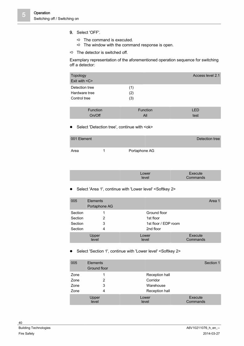
9. Select 'OFF'.
The command is executed. The window with the command response is open.
The detector is switched off.
Exemplary representation of the aforementioned operation sequence for switchingoff a detector:
TopologyExit with <C>
Access level 2.1
Detection treeHardware treeControl tree
(1)(2)(3)
FunctionOn/Off
FunctionAll
LEDtest
Select 'Detection tree', continue with <ok>
001 Element Detection tree
Area 1 Portaphone AG
Lowerlevel
ExecuteCommands
Select 'Area 1', continue with 'Lower level' <Softkey 2>
005 ElementsPortaphone AG
Area 1
SectionSectionSectionSection
1234
Ground floor1st floor1st floor / EDP room2nd floor
Upperlevel
Lowerlevel
ExecuteCommands
Select 'Section 1', continue with 'Lower level' <Softkey 2>
005 ElementsGround floor
Section 1
ZoneZoneZoneZone
1234
Reception hallCorridorWarehouseReception hall
Upperlevel
Lowerlevel
ExecuteCommands

Operation 5Switching off / Switching on
41Building Technologies A6V10211076_h_en_--Fire Safety 2014-03-27
Select element 'Zone 1', continue with 'Lower level' <softkey 2>
002 ElementsReception hall
Zone 1
Detect.Detect.
12
Main entranceReception
Upperlevel
MoreOptions
Select 'Detect. 2', continue with 'More Options' <softkey 3>
Selecting option
Execute commandsJump to linkShow details
(3)(4)(5)
Select 'Execute commands' option, continue with <ok>
Select command
OFFActivate alarm indicatorDeactivate alarm indicator
(1)(3)(4)
Select 'OFF' command
Command response
Execute commandOFF
Command executed
5 OperationSwitching off / Switching on
42Building Technologies A6V10211076_h_en_--Fire Safety 2014-03-27
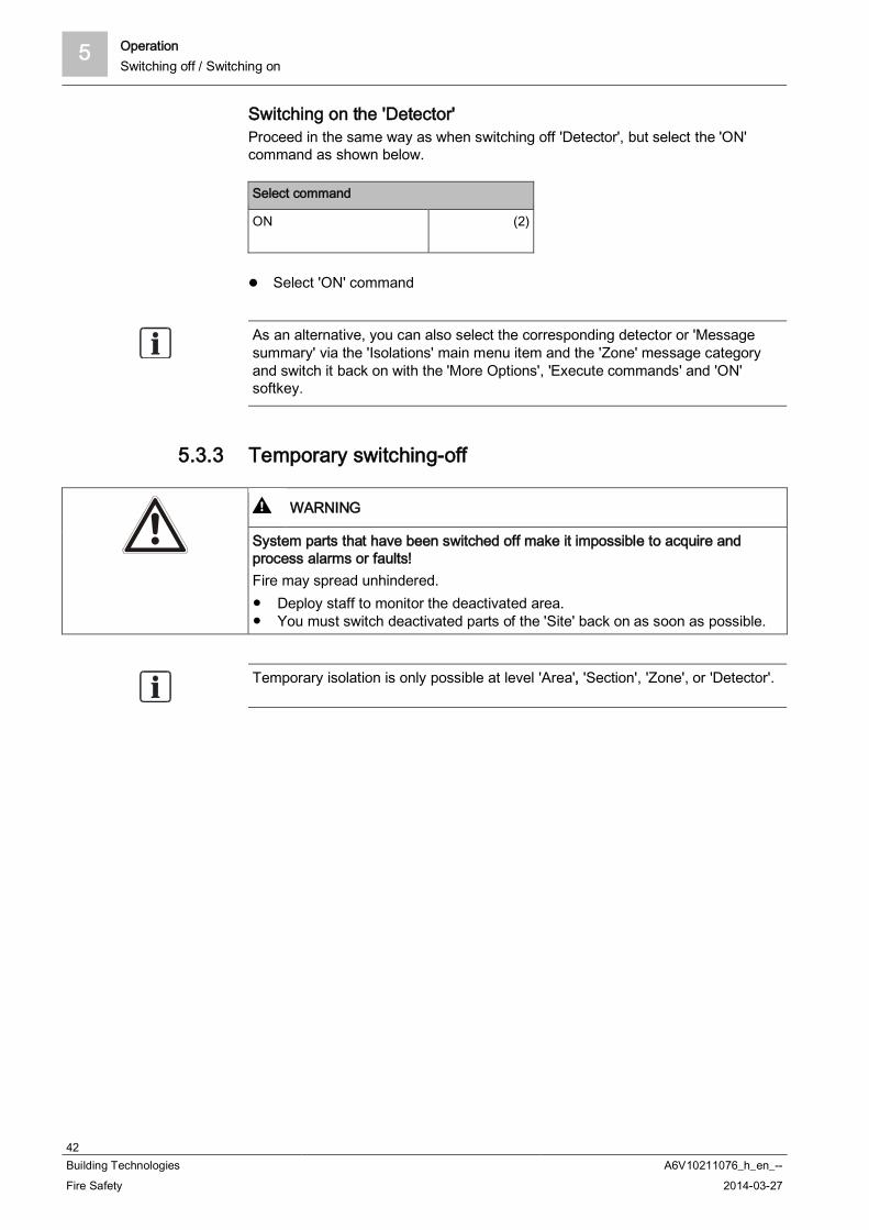
Switching on the 'Detector'Proceed in the same way as when switching off 'Detector', but select the 'ON'command as shown below.
Select command
ON (2)
Select 'ON' command
As an alternative, you can also select the corresponding detector or 'Messagesummary' via the 'Isolations' main menu item and the 'Zone' message categoryand switch it back on with the 'More Options', 'Execute commands' and 'ON'softkey.
5.3.3 Temporary switching-off
WARNING
System parts that have been switched off make it impossible to acquire andprocess alarms or faults!Fire may spread unhindered.
Deploy staff to monitor the deactivated area.You must switch deactivated parts of the 'Site' back on as soon as possible.
Temporary isolation is only possible at level 'Area', 'Section', 'Zone', or 'Detector'.

Operation 5Switching off / Switching on
43Building Technologies A6V10211076_h_en_--Fire Safety 2014-03-27
Override for different settings
If a detector has been temporarily isolated and its 'Zone' has been permanentlyisolated, the detector is also permanently isolated.
If a detector has been temporarily isolated and its 'Zone' has been temporarilyisolated, the time limit for the isolation of the 'Zone' also applies for the detector.
If all detectors in a 'Zone' have been isolated and the time limit for the isolation ofa detector elapses, the 'Zone' is displayed as switched on.
The 'Temporary switching-off' function can be used to set a time limit for 'Isolation'.The switched off part of the 'Isolation' is switched back on automatically after thetime period entered.The figures below show an exemplary operation sequence to temporarily switch off'Section':
1. In the 'Main menu', select the 'Element search' menu item.
2. Select 'Start with category'.
Selecting element category
ZoneAreaSectionDetectorRT control
(1)(2)(3)(4)(5)
Select 'Section' and confirm with <ok>.
Enter address
Section 1--------Confirm with <ok>/Exit with <C>Delete with <Cursor up>
Enter the address: e.g., 1. Confirm with <ok>.
Select command
All zones ONAll zones OFF/timerMCP zones OFFNon-MCP zones ONNon-MCP zones OFF
(2)(3)(4)(5)(6)
Select 'All zones OFF/timer' and confirm with <ok>.
5 OperationSwitching off / Switching on
44Building Technologies A6V10211076_h_en_--Fire Safety 2014-03-27
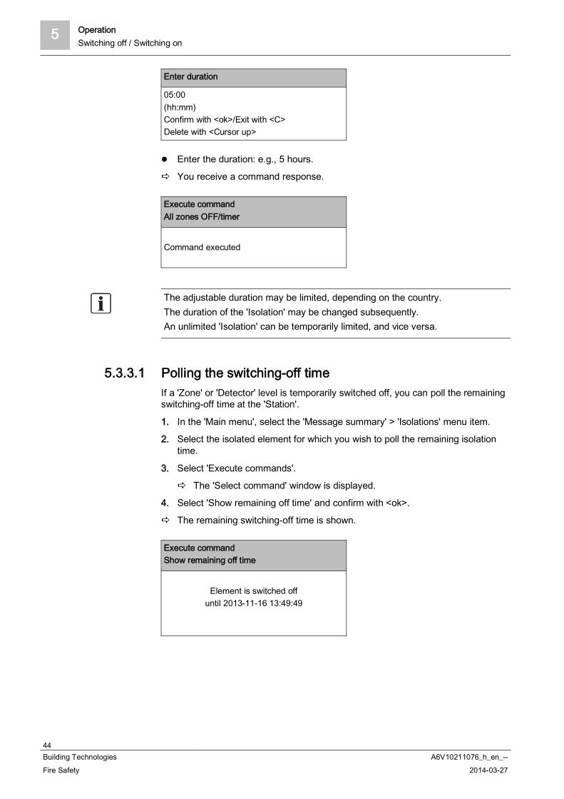
Enter duration
05:00(hh:mm)Confirm with <ok>/Exit with <C>Delete with <Cursor up>
Enter the duration: e.g., 5 hours.
You receive a command response.
Execute commandAll zones OFF/timer
Command executed
The adjustable duration may be limited, depending on the country.The duration of the 'Isolation' may be changed subsequently.An unlimited 'Isolation' can be temporarily limited, and vice versa.
5.3.3.1 Polling the switching-off timeIf a 'Zone' or 'Detector' level is temporarily switched off, you can poll the remainingswitching-off time at the 'Station'.
1. In the 'Main menu', select the 'Message summary' > 'Isolations' menu item.
2. Select the isolated element for which you wish to poll the remaining isolationtime.
3. Select 'Execute commands'.
The 'Select command' window is displayed.
4. Select 'Show remaining off time' and confirm with <ok>.
The remaining switching-off time is shown.
Execute commandShow remaining off time
Element is switched offuntil 2013-11-16 13:49:49
Operation 5Switching off / Switching on
45Building Technologies A6V10211076_h_en_--Fire Safety 2014-03-27
5.3.3.2 Expiry reminder for temporary switching-offAn expiry reminder is displayed prior to the expiry of temporary isolation. You canconfigure how long before a temporary isolation the reminder is displayed in'Cerberus-Engineering-Tool'.
The expiry reminder must be configured in 'Cerberus-Engineering-Tool' > taskcard 'Operation' > 'Global system configuration' > 'Global behaviour' > 'Details'tab.
You will find more information about configuring the expiry reminder in document'A6V10210424'. See chapter 'Applicable documents'.
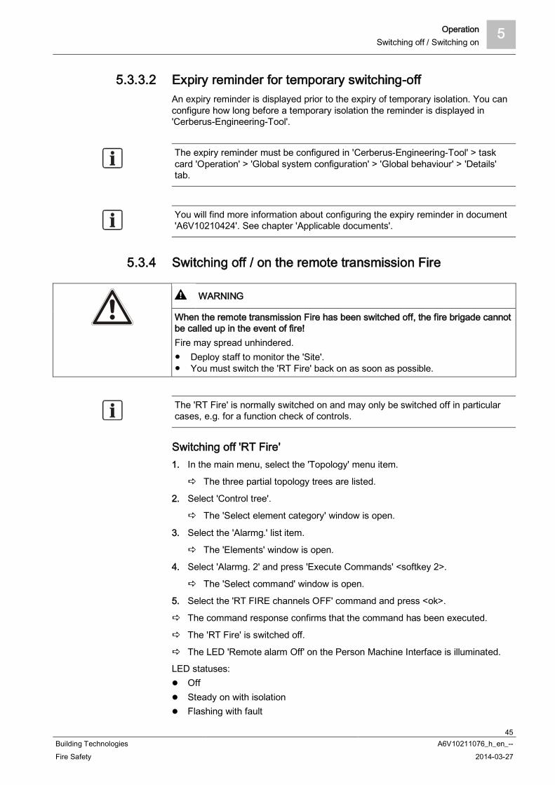
5.3.4 Switching off / on the remote transmission Fire
WARNING
When the remote transmission Fire has been switched off, the fire brigade cannotbe called up in the event of fire!Fire may spread unhindered.
Deploy staff to monitor the 'Site'.You must switch the 'RT Fire' back on as soon as possible.
The 'RT Fire' is normally switched on and may only be switched off in particularcases, e.g. for a function check of controls.
Switching off 'RT Fire'1. In the main menu, select the 'Topology' menu item.
The three partial topology trees are listed.
2. Select 'Control tree'.
The 'Select element category' window is open.
3. Select the 'Alarmg.' list item.
The 'Elements' window is open.
4. Select 'Alarmg. 2' and press 'Execute Commands' <softkey 2>.
The 'Select command' window is open.
5. Select the 'RT FIRE channels OFF' command and press <ok>.
The command response confirms that the command has been executed.
The 'RT Fire' is switched off.
The LED 'Remote alarm Off' on the Person Machine Interface is illuminated.
LED statuses: Off Steady on with isolation Flashing with fault
5 OperationSwitching off / Switching on
46Building Technologies A6V10211076_h_en_--Fire Safety 2014-03-27
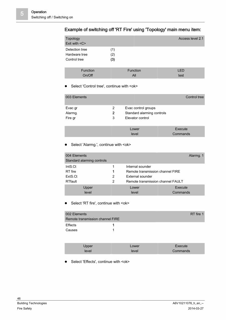
Example of switching off 'RT Fire' using 'Topology' main menu item:
TopologyExit with <C>
Access level 2.1
Detection treeHardware treeControl tree
(1)(2)(3)
FunctionOn/Off
FunctionAll
LEDtest
Select 'Control tree', continue with <ok>
003 Elements Control tree
Evac grAlarmg.Fire gr
223
Evac control groupsStandard alarming controlsElevator control
Lowerlevel
ExecuteCommands
Select 'Alarmg.', continue with <ok>
004 ElementsStandard alarming controls
Alarmg. 1
IntS.CtRT fireExtS.CtRTfault
1122
Internal sounderRemote transmission channel FIREExternal sounderRemote transmission channel FAULT
Upperlevel
Lowerlevel
ExecuteCommands
Select 'RT fire', continue with <ok>
002 ElementsRemote transmission channel FIRE
RT fire 1
EffectsCauses
11
Upperlevel
Lowerlevel
ExecuteCommands
Select 'Effects', continue with <ok>

Operation 5Switching off / Switching on
47Building Technologies A6V10211076_h_en_--Fire Safety 2014-03-27
001 Element Effects
RT ch. 1
Upperlevel
MoreOptions
Continue with <More Options>
Selecting option
Execute commandsJump to linkShow details
(3)(4)(5)
Select 'Execute commands' option, continue with <ok>
Select command
OFFSet customer textActivateTime limited activation
(1)(3)(5)(6)
Select 'OFF' command continue with <ok>
Command response
Execute commandOFF
Command executed
Example of switching off 'RT Fire' using 'On / Off' menu item in'Functions' menu:
Selecting element category
ZoneSounderFire control groupRT controlAlarming control group
(3)(4)(5)(6)(7)
Select 'Alarming control group' element category, continue with <ok>

5 OperationSwitching off / Switching on
48Building Technologies A6V10211076_h_en_--Fire Safety 2014-03-27
Enter address
Alarmg. ---------Confirm with <ok>/Exit with <C>Delete with <Cursor up>
Do not enter an address, continue with <ok>
Select command
Internal/external sounders OFFRT FIRE channels OFFInternal/external sounders ONRT FIRE channels ON
(1)(2)(3)(4)
Select command: 'RT FIRE channels OFF'
Switching on 'RT Fire' Proceed as with switching off, but select the 'ON' command.
5.3.5 Switching off alarm activation
WARNING
System parts that have been switched off make it impossible to acquire andprocess alarms or faults!Fire may spread unhindered.
Deploy staff to monitor the deactivated area.You must switch deactivated parts of the 'Site' back on as soon as possible.
You can switch off the fire detection installation alarm activation for specificelements with this function.Faults such as the removal of a detector are nevertheless evaluated and displayed.
You can only run the 'Alarm evaluation OFF' command on the followingelements:'XC10 zone''Section''Automatic zone''Technical zone'

Operation 5Log in / Change access level
49Building Technologies A6V10211076_h_en_--Fire Safety 2014-03-27
5.3.6 Switching off sabotage evaluation [DE] If a class 3 key safe (fire department key safe, 'FSD') forms part of the firedetection installation and you want to open the housing of the control panel, youhave got to switch off the sabotage evaluation.
NOTICE
Sabotage ALARM with police or security serviceCosts due to unnecessary deployment.
In a site with 'FSD', switch off sabotage evaluation before you open thehousing of a control panel.
'Sabotage evaluation OFF' Sabotage evaluation is switched on.
You have access level 3 authorization.
1. In the main menu, select the 'Topology' menu item.
The three partial trees of the topology tree are indicated.
2. Select 'Hardware tree'.
One or more 'Stations' are displayed.
3. Select the 'Stations' to which 'FSD' is connected.
4. Press 'Lower level' <softkey>.
The elements of 'Stations' are displayed.
5. Select the element 'FSD'.
6. Press <Execute Commands>.
7. Select the 'Sabotage evaluation OFF' command.
Sabotage evaluation is switched off.
5.4 Log in / Change access levelYou can enable an 'Access level' by entering your PIN in the PIN entry dialog, or bypressing <ok>. Alternatively you can use the key switch (optional) to release anAccess level.If you press a key on the Person Machine Interface whose function requires ahigher 'Access level', the PIN input dialog is displayed automatically.
Login/logout
Enter PIN: ****Logout or guest-login: no PIN + <ok>
Confirm with <ok>/Exit with <C>Delete with <Cursor up>
PIN entry dialog box
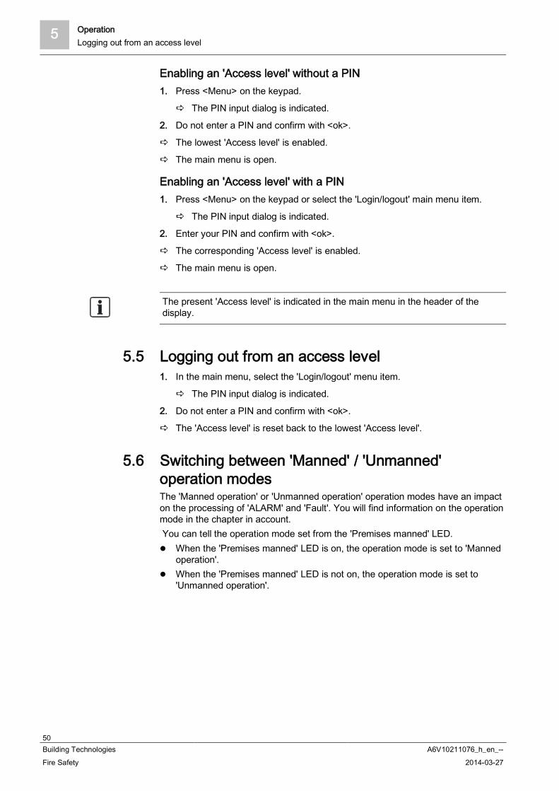
5 OperationLogging out from an access level
50Building Technologies A6V10211076_h_en_--Fire Safety 2014-03-27
Enabling an 'Access level' without a PIN1. Press <Menu> on the keypad.
The PIN input dialog is indicated.
2. Do not enter a PIN and confirm with <ok>.
The lowest 'Access level' is enabled.
The main menu is open.
Enabling an 'Access level' with a PIN1. Press <Menu> on the keypad or select the 'Login/logout' main menu item.
The PIN input dialog is indicated.
2. Enter your PIN and confirm with <ok>.
The corresponding 'Access level' is enabled.
The main menu is open.
The present 'Access level' is indicated in the main menu in the header of thedisplay.
5.5 Logging out from an access level1. In the main menu, select the 'Login/logout' menu item.
The PIN input dialog is indicated.
2. Do not enter a PIN and confirm with <ok>.
The 'Access level' is reset back to the lowest 'Access level'.
5.6 Switching between 'Manned' / 'Unmanned'operation modesThe 'Manned operation' or 'Unmanned operation' operation modes have an impacton the processing of 'ALARM' and 'Fault'. You will find information on the operationmode in the chapter in account. You can tell the operation mode set from the 'Premises manned' LED.
When the 'Premises manned' LED is on, the operation mode is set to 'Mannedoperation'.
When the 'Premises manned' LED is not on, the operation mode is set to'Unmanned operation'.

Operation 5Switching between 'Manned' / 'Unmanned' operation modes
51Building Technologies A6V10211076_h_en_--Fire Safety 2014-03-27
Switching between operation modes1. Press the 'Premises manned' standard button on the PMI.
The PIN input dialog is indicated.
2. Enter your PIN and confirm with <ok>.
The operation mode has been switched.
Check the setting of the 'Premises manned' LED.
'Manned operation' / 'Unmanned operation' mixed operationIf one PMI has visibility to more than one fire control panel, with different 'Mannedoperation' / 'Unmanned operation' operation modes, this is considered "mixedoperation".In this case, the event list opens upon actuation of the 'Premises manned' button.The event list includes all events of the 'Manned operation' and 'Unmannedoperation' operation modes.With the 'More Options' softkey the three following commands are available:
'Switch all to 'manned'' 'Switch all to 'unmanned'' 'Manned' or 'Unmanned', depending on the condition of the selected entry in
the event list
When there is at least one 'Premises manned' event, the 'Premises manned' LEDis on.By means of configured switching from 'Manned operation' to 'Unmannedoperation' at predefined times, the operation mode may switch although nomanual switching has been performed.There is no possibility of an automatic switching from 'Unmanned operation' to'Manned operation'.
See also Operation modes [ 97]

5 OperationChanging visibility
52Building Technologies A6V10211076_h_en_--Fire Safety 2014-03-27
5.7 Changing visibilitySee also
Visibility [ 100]
5.7.1 Deactivating standby
'PMI standby visibility' cannot be activated manually.The 'Deactivate standby visibility' command is only available once the monitored'Station' or the management station is back in normal operation.
The 'PMI standby visibility' is active.
The monitored 'Station' or the management station is in normal operation.
1. In the 'Main menu', select the 'Message summary' menu item.
The message categories containing messages are displayed.
2. Select 'Information'.
'PMI standby visibility' is shown.
3. Select this element.
4. Press <Execute Commands>.
5. Select 'Deactivate standby visibility'
'PMI standby visibility' is deactivated.
See also Standby visibility [ 101]
5.7.2 Activating / deactivating expanded visibility
The 'Activate expanded visibility' function can be assigned to a favorite to make iteasier to find.Activation can be configured depending on the condition.
Activating the function 'Expanded visibility' The 'Station' is configured for 'Expanded visibility'.
1. In the 'Main menu', select the 'Topology' menu item.
The three partial trees of the 'Topology' are displayed.
2. Select 'Hardware tree'.
The elements in 'Hardware tree' are displayed.
3. Select 'Station' and press the 'Lower level' softkey.
The elements of 'Station' are displayed.
4. Select 'PMI' and press the 'Lower level' softkey.
The elements of 'PMI' are displayed.

Operation 5Main menu / Open menu item
53Building Technologies A6V10211076_h_en_--Fire Safety 2014-03-27
5. Select the 'expand.' element and press the 'More Options' softkey or thecommand at the bottom directly, depending on the 'Access level'.
The 'Selection option' window is displayed depending on the 'Access level'.
6. Select 'Execute commands'.
The 'Select command' window is displayed.
7. Select 'Activate expanded visibility'
'Expanded visibility' is activated.
Deactivating the 'Expanded visibility' function1. In the 'Main menu', select the 'Message summary' menu item.
The message categories containing messages are displayed.
2. Select 'Information'.
3. 'PMI expanded visibility' is shown.
4. Select this element.
5. Press <Execute Commands>.
6. Select 'Deactivate expanded visibility'.
'PMI expanded visibility' is deactivated.
See also Expanded visibility [ 101]
5.8 Main menu / Open menu itemOpening 'Main menu'1. Press the <Menu> button.
The PIN input dialog is indicated.
2. Enter your PIN and confirm with <ok> or confirm with <ok> without entering thePIN.
The 'Main menu' is indicated on the display.
Without PIN entry, the 'Main menu' only includes the menu items that areavailable without logging-in. To view an extended menu list in the 'Main menu',you need to log in on a corresponding access level.
Opening menu itemEvery menu item has a number shown in brackets for the shortcut on the numericalblock.
Press on the digit in account on the numerical pad in order to open the menuitem.
Alternatively, you can navigate to the next menu item using the navigationbuttons < > and < >.
You can open the highlighted menu item with the button <ok> or with thenavigation button < >.
See also Menu button [ 19]

5 OperationExecute commands – Basics
54Building Technologies A6V10211076_h_en_--Fire Safety 2014-03-27
5.9 Execute commands – BasicsThere are different ways to enter commands. There are basically two ways ofentering commands:
Function-oriented command entry– Here, first select a command and then the target object on which the
command is to be executed. Object-oriented command entry
– Here, first select the target object and then the command on which thetarget object is to be executed.
In the fire detection system, these two methods of entering commands arecombined in the interest of a better overview during the selection. It is possible toswitch between the two methods during the command entry sequence.As only the possible command or element categories are indicated, each selectionrestricts the selection that follows.The example in the following chapter makes this clear.
Depending on the 'Access level', the possible selection of commands via softkeysor the 'Main menu' is extended or restricted.
See also Selection in the topology [ 60] Searching for elements [ 61] Commands with required access levels [ 102]
5.9.1 Execute commands – General
Example for the execution of commands1. Select a command category such as e.g. 'Function On/Off' by pressing the
<softkey 1> in the 'Main menu' or the 'Functions' main menu item.
The pre-selection restricts the element category selection. A list of all element categories on which a command of the 'On / Off'
command group can be executed is indicated.
2. Select an element category.
The 'Enter address' window is open.
3. Enter an address or leave the entry field blank and confirm with <ok>.
If no address is entered, all elements of the selected element category areindicated.
4. In this case, select an element and press the 'Execute Commands' <softkey>.
The 'Select command' window is open.
5. Select a command.
The command is executed.
The tables below indicate the steps described above:
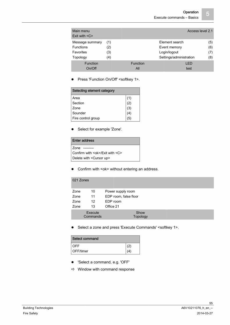
Operation 5Execute commands – Basics
55Building Technologies A6V10211076_h_en_--Fire Safety 2014-03-27
Main menuExit with <C>
Access level 2.1
Message summaryFunctionsFavoritesTopology
(1)(2)(3)(4)
Element searchEvent memoryLogin/logoutSettings/administration
(5)(6)(7)(8)
FunctionOn/Off
FunctionAll
LEDtest
Press 'Function On/Off' <softkey 1>.
Selecting element category
AreaSectionZoneSounderFire control group
(1)(2)(3)(4)(5)
Select for example 'Zone'.
Enter address
Zone ---------Confirm with <ok>/Exit with <C>Delete with <Cursor up>
Confirm with <ok> without entering an address.
021 Zones
ZoneZoneZoneZone
10111213
Power supply roomEDP room, false floorEDP roomOffice 21
ExecuteCommands
ShowTopology
Select a zone and press 'Execute Commands' <softkey 1>.
Select command
OFFOFF/timer
(2)(4)
'Select a command, e.g. 'OFF'
Window with command response
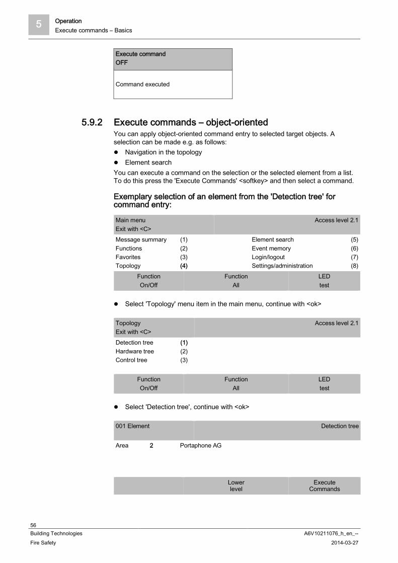
5 OperationExecute commands – Basics
56Building Technologies A6V10211076_h_en_--Fire Safety 2014-03-27
Execute commandOFF
Command executed
5.9.2 Execute commands – object-orientedYou can apply object-oriented command entry to selected target objects. Aselection can be made e.g. as follows:
Navigation in the topology Element search
You can execute a command on the selection or the selected element from a list.To do this press the 'Execute Commands' <softkey> and then select a command.
Exemplary selection of an element from the 'Detection tree' forcommand entry:
Main menuExit with <C>
Access level 2.1
Message summaryFunctionsFavoritesTopology
(1)(2)(3)(4)
Element searchEvent memoryLogin/logoutSettings/administration
(5)(6)(7)(8)
FunctionOn/Off
FunctionAll
LEDtest
Select 'Topology' menu item in the main menu, continue with <ok>
TopologyExit with <C>
Access level 2.1
Detection treeHardware treeControl tree
(1)(2)(3)
FunctionOn/Off
FunctionAll
LEDtest
Select 'Detection tree', continue with <ok>
001 Element Detection tree
Area 2 Portaphone AG
Lowerlevel
ExecuteCommands

Operation 5Execute commands – Basics
57Building Technologies A6V10211076_h_en_--Fire Safety 2014-03-27
Select 'Area 2', continue with 'Lower level' <softkey 2>
005 ElementsPortaphone AG
Area 2
SectionSectionSectionSection
1234
Ground floor1. floor1. floor / EDP room2. floor
Upperlevel
Lowerlevel
ExecuteCommands
Select 'Section 1', continue with 'Lower level' <Softkey 2>
005 ElementsGround floor
Section 1
ZoneZoneZoneZone
1234
Reception hallCorridorWarehouseReception hall
Upperlevel
Lowerlevel
ExecuteCommands
Select 'Zone 1', continue with 'Lower level' <Softkey 2>
002 ElementsReception hall
Zone 1
Detect.Detect.
12
Main entranceReception
Upperlevel
ExecuteCommands
Select 'Detect. 1', continue with 'Execute Commands' <softkey 3>
Select command
OFFActivate alarm indicatorDeactivate alarm indicator
(1)(3)(4)
Select 'OFF' command continue with <ok>
Command response
Execute commandOFF
Command executed
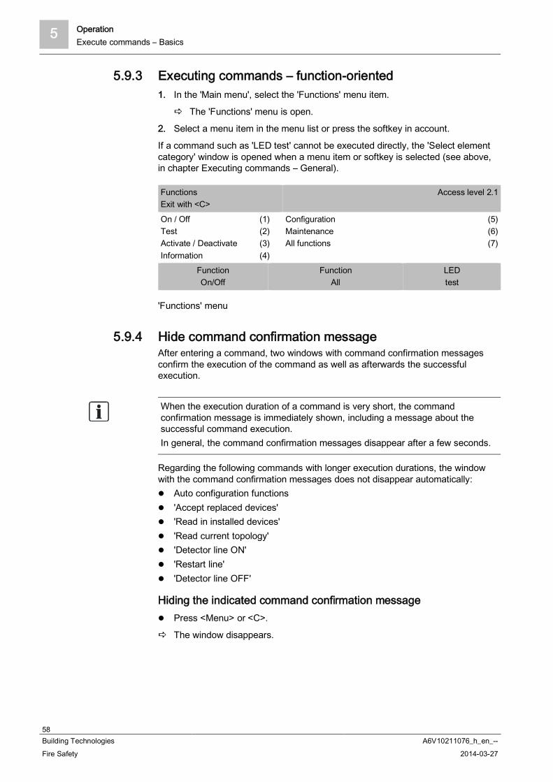
5 OperationExecute commands – Basics
58Building Technologies A6V10211076_h_en_--Fire Safety 2014-03-27
5.9.3 Executing commands – function-oriented1. In the 'Main menu', select the 'Functions' menu item.
The 'Functions' menu is open.
2. Select a menu item in the menu list or press the softkey in account.
If a command such as 'LED test' cannot be executed directly, the 'Select elementcategory' window is opened when a menu item or softkey is selected (see above,in chapter Executing commands – General).
FunctionsExit with <C>
Access level 2.1
On / OffTestActivate / DeactivateInformation
(1)(2)(3)(4)
ConfigurationMaintenanceAll functions
(5)(6)(7)
FunctionOn/Off
FunctionAll
LEDtest
'Functions' menu
5.9.4 Hide command confirmation messageAfter entering a command, two windows with command confirmation messagesconfirm the execution of the command as well as afterwards the successfulexecution.
When the execution duration of a command is very short, the commandconfirmation message is immediately shown, including a message about thesuccessful command execution.In general, the command confirmation messages disappear after a few seconds.
Regarding the following commands with longer execution durations, the windowwith the command confirmation messages does not disappear automatically:
Auto configuration functions 'Accept replaced devices' 'Read in installed devices' 'Read current topology' 'Detector line ON' 'Restart line' 'Detector line OFF'
Hiding the indicated command confirmation message Press <Menu> or <C>.
The window disappears.

Operation 5Selecting elements or events
59Building Technologies A6V10211076_h_en_--Fire Safety 2014-03-27
5.10 Selecting elements or eventsThe objective of selecting an element or event is e.g. the detailed and informationindication, the configuration or command entry applied to the selection.
5.10.1 Select eventsAll events that have occurred in the fire detection installation are stored in the eventmemory . The event list is sorted chronologically and you may filter the events bycategory, date and time.
The preselection by category as well as the entry of a timespan makes it possibleto indicate a part of all the events stored in 'Event memory'.
Selecting events1. In the 'Main menu', select the 'Event memory' menu item.
A list with 'Stations' is displayed. The 'Stations', where the selection ismade is identified accordingly.
2. Select the 'Station'.
A list of all events is displayed.
0008/0069 AAAAA bbttt 06-05-19 00:00:01 ttt 06-05-25 08:48:29
06-05-23 09:25:36YY 13
ZZZABCDEFGHI
ZZZABCDEFGHI
ZZZABCDEFGHI
VVVVVGGGGGG
STST 01
06-05-22 08:16:05ZZ 13 VVVVV
GGGGGG1
32
4
Example of an event list
1 Event list
2 Timespan3 Highlighted entry (0008) of the total number of entries (0069)
4 Selected 'Station'
Using the softkeys to limit the selection of all events indicatedYou can use the 'Select Event category' softkey to select an event category andthen enter the date or time range.
Select event category
ALARMPre-ALARMFaultIsolation
(0)(1)(2)(3)

5 OperationSelecting elements or events
60Building Technologies A6V10211076_h_en_--Fire Safety 2014-03-27
You can use the 'Select Date/time range' softkey to enter the timespan.
Select date/time range
Whole rangeFrom / toTodayYesterdayLast 7 days
(1)(2)(3)(4)
The 'More Options' softkey gives you the following options:
Selecting option
Select stationExecute commandsJump to beginJump to endDelete event memory
(3)(4)(5)(6)(8)
5.10.2 Selection in the topologyIt is possible to navigate through the topology tree structure via the 'Topology'menu item in the Main menu. Here you can select an element in order to viewdetails or execute a function on a selected element.In the topology, you pre-select elements by selecting the subtree in the topology.There are three partial trees:
'Detection tree' 'Hardware tree' 'Control tree'
Selecting element in the topology1. In the 'Main menu', select the 'Topology' menu item.
The three partial trees of the topology are indicated.
2. Select a subtree.
3. In the structure, continue navigating to the detail with the 'Lower level' softkeyor use the 'Execute Commands' <softkey> to execute a command.
Details are shown or the window with a selection of commands is indicated.
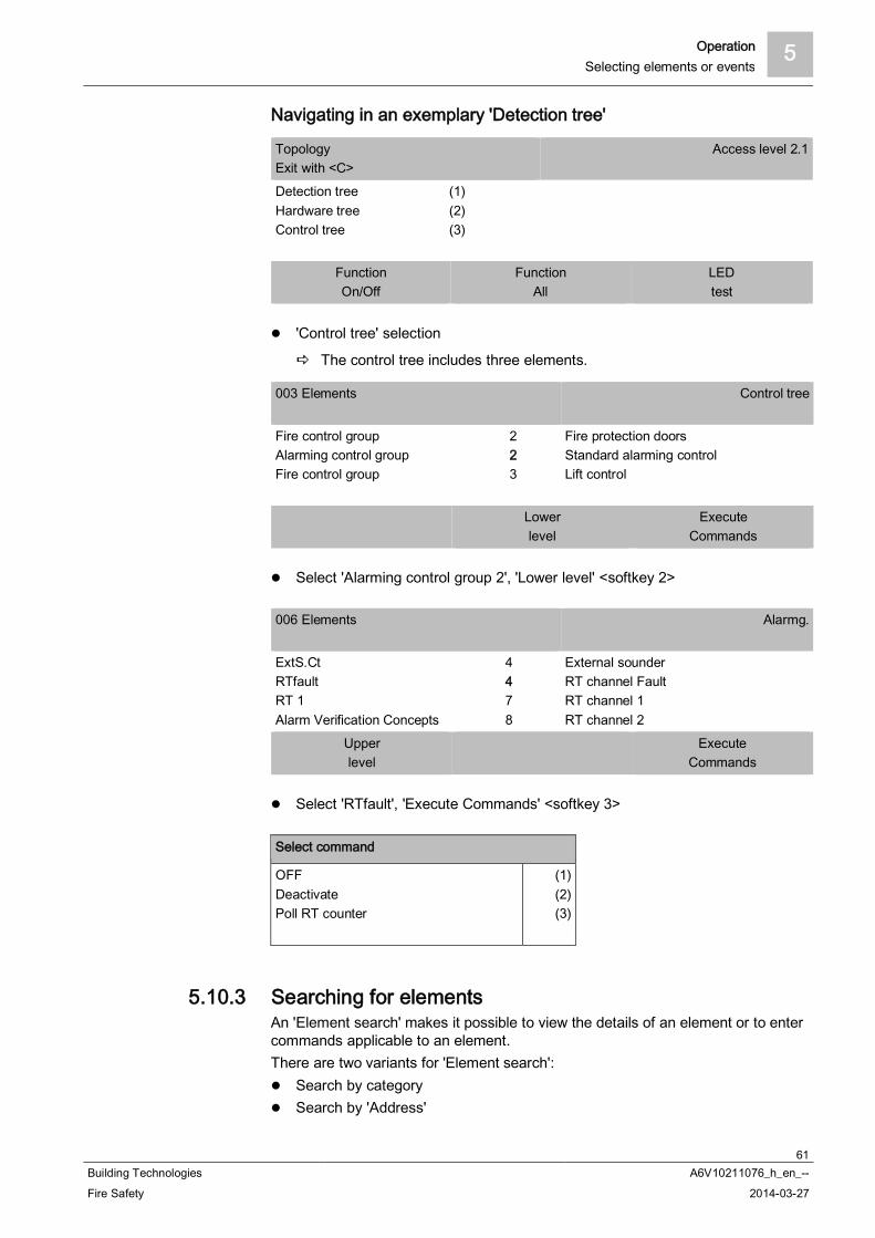
Operation 5Selecting elements or events
61Building Technologies A6V10211076_h_en_--Fire Safety 2014-03-27
Navigating in an exemplary 'Detection tree'
TopologyExit with <C>
Access level 2.1
Detection treeHardware treeControl tree
(1)(2)(3)
FunctionOn/Off
FunctionAll
LEDtest
'Control tree' selection
The control tree includes three elements.
003 Elements Control tree
Fire control groupAlarming control groupFire control group
223
Fire protection doorsStandard alarming controlLift control
Lowerlevel
ExecuteCommands
Select 'Alarming control group 2', 'Lower level' <softkey 2>
006 Elements Alarmg.
ExtS.CtRTfaultRT 1Alarm Verification Concepts
4478
External sounderRT channel FaultRT channel 1RT channel 2
Upperlevel
ExecuteCommands
Select 'RTfault', 'Execute Commands' <softkey 3>
Select command
OFFDeactivatePoll RT counter
(1)(2)(3)
5.10.3 Searching for elementsAn 'Element search' makes it possible to view the details of an element or to entercommands applicable to an element.There are two variants for 'Element search':
Search by category Search by 'Address'
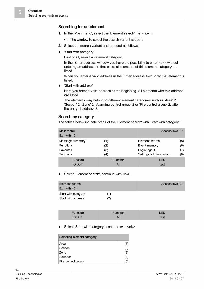
5 OperationSelecting elements or events
62Building Technologies A6V10211076_h_en_--Fire Safety 2014-03-27
Searching for an element1. In the 'Main menu', select the 'Element search' menu item.
The window to select the search variant is open.
2. Select the search variant and proceed as follows:
'Start with category'First of all, select an element category.In the 'Enter address' window you have the possibility to enter <ok> withoutentering an address. In that case, all elements of this element category arelisted.When you enter a valid address in the 'Enter address' field, only that element islisted.
'Start with address'Here you enter a valid address at the beginning. All elements with this addressare listed.The elements may belong to different element categories such as 'Area' 2,'Section' 2, 'Zone' 2, 'Alarming control group' 2 or 'Fire control group' 2, afterthe entry of address 2.
Search by categoryThe tables below indicate steps of the 'Element search' with 'Start with category':
Main menuExit with <C>
Access level 2.1
Message summaryFunctionsFavoritesTopology
(1)(2)(3)(4)
Element searchEvent memoryLogin/logoutSettings/administration
(5)(6)(7)(8)
FunctionOn/Off
FunctionAll
LEDtest
Select 'Element search', continue with <ok>
Element searchExit with <C>
Access level 2.1
Start with categoryStart with address
(1)(2)
FunctionOn/Off
FunctionAll
LEDtest
Select 'Start with category', continue with <ok>
Selecting element category
AreaSectionZoneSounderFire control group
(1)(2)(3)(4)(5)

Operation 5Selecting elements or events
63Building Technologies A6V10211076_h_en_--Fire Safety 2014-03-27
Select e.g. 'Zone', continue with <ok>
Enter address
Zone 2--------Confirm with <ok>/Exit with <C>Delete with <Cursor up>
Enter e.g. 2, continue with <ok>
001 Zone
Zone 2 Corridor
ExecuteCommands
Execute commandsTopology
Corresponding functions are possible with the softkeys.
Search by addressThe tables below indicate steps of the 'Element search' with 'Start with address':
Element searchExit with <C>
Access level 2.1
Start with categoryStart with address
(1)(2)
FunctionOn/Off
FunctionAll
LEDtest
Select 'Start with address', continue with <ok>
Enter address
Address 2--------Confirm with <ok>/Exit with <C>Delete with <Cursor up>
Enter e.g. 2, continue with <ok>
050 Elements
AreaSectionZoneRT fire
2222
Portaphone AG1st floorCorridorRT channel Fire
ExecuteCommands
Execute commandsTopology
Corresponding functions are possible with the softkeys.

5 OperationTesting
64Building Technologies A6V10211076_h_en_--Fire Safety 2014-03-27
5.11 TestingThe following chapters with operation sequences for testing include sample tests.
See also Test [ 98]
5.11.1 Testing detectors For 'Detector test' you can select automatic 'Detectors' or 'Manual call point'.The 'Detector test' function can be carried out on the levels 'Zone', 'Section' or'Area'.
Testing all automatic 'Detectors'1. In the 'Main menu', select the 'Functions' menu item.
The 'Functions' menu is open.
2. Select the 'Test' menu item.
The 'Select element category' window is open.
3. Select the 'Element category' 'Area'.
The 'Enter address' window is open.
4. Press <ok> without entering an address.
The 'Select command' window is open.
5. Select 'Non-MCP zones det.test'.
All automatic 'Detectors' are set to 'Detector test'. The 'DETECTOR TEST' LED on the Person Machine Interface is on.
6. Test the 'Detectors'.
Example of selecting commands for the 'Detector test' of allautomatic 'Detectors':
Select command
Installation testNon-MCP zones det.test ENDInstallation test ENDMCP zones det.test ENDNon-MCP zones det.test
(2)(3)(4)(5)(6)
'Detector test' all automatic 'Detectors'Proceed as with Detector test but select the 'Non-MCP zones det.test END'command.

Operation 5Testing
65Building Technologies A6V10211076_h_en_--Fire Safety 2014-03-27
5.11.2 Carry out 'Installation test'As in the 'Installation test' all functions of the complete fire detection systemincluding the 'Fire control' and alarming are tested, you must take appropriateactions.The 'Installation test' can be carried out at 'Area' or 'Section' levels.
WARNING
During the system test, the alarming and fire control are activated!Personal injury resulting from extinguishing activationThe fire brigade is called up unnecessarily.
Set the 'Fire controls' to 'Control test' in advance.Inform the fire brigade in advance.
Before the 'Installation test' you can set 'Fire controls' to 'Control test'.
Testing the installation Proceed as with 'Detector test' and select the 'Installation test' function.
See also Control test [ 65] Testing detectors [ 64]
5.11.3 Control test The 'Control test' checks the function of configured controls.
During the 'Control test', the controls function in the same way as during normaloperation; however, the hardware is not actuated.
The effects of the controls, e.g. the actuation of digital outputs and the sounders orthe execution of commands is ensured, but the respective hardware receives nosignal and is thus not activated.
All controls can be set to 'Control test'.
Testing a control1. In the main menu, select the 'Functions' menu item.
The 'Functions' window is open.
2. Select the 'Test' menu item.
A list of all element categories on which a command of the 'Test' commandgroup can be executed is indicated.
3. Select the 'Fire control group' element category.
The 'Enter address' window is open.

5 OperationTesting
66Building Technologies A6V10211076_h_en_--Fire Safety 2014-03-27
4. Press <ok> without entering an address.
A list of all 'Fire control groups' is displayed.
5. Select the desired 'Fire control group' and press <softkey 1>.
The 'Select command' window is open.
6. Select 'Control test'.
The control test is performed.
Example of selecting commands for the 'Control test' in the 'Firecontrol group' element category:
Selecting element category
SectionZoneSounderRT controlFire control group
(2)(3)(4)(5)(6)
Select command
Control test ENDControl test
(1)(2)
See also Testing detectors [ 64]
5.11.4 Testing indicators The display test is a functional hardware check for the following indicationelements:
Display LEDs Buzzer
At the same time, indication and operation devices that have been installed asoptions, e.g. the mimic display driver or fire department operating panels, areactivated by commands if they offer the possibility of performing a display test.The test takes 10 seconds and has two phases of 5 seconds each.
Depending on the configuration, the 'LED test' command is available as softkey inthe 'Main menu'.

Operation 5Activation / Deactivation / Reset
67Building Technologies A6V10211076_h_en_--Fire Safety 2014-03-27
Testing the indicators and displays1. In the 'Main menu', select the 'Settings/administration' menu item.
2. Select the 'LED test' menu item.
Phase 1 starts:Display is totally white.LEDs are in color mode 1.
Phase 2 starts:Display is totally black.LEDs are in color mode 2.
5.12 Activation / Deactivation / ResetYou can activate and deactivate outputs, for example 'Sounders'.Channel inputs, e.g. detectors, may be activated but not deactivated. These can bereset after activation.When 'Fire controls' is activated, this triggers smoke dampers, elevators, systemequipment, and extinguishing equipment (including those with extinguishinggases), for example. You must take appropriate measures to prevent any possibledamage.
WARNING
Deactivated controls hinder appropriate measures in case of fire!Personal injury and damage to property in the event of a fire.
Deploy staff to monitor the deactivated area.You must reactivate deactivated controls as soon as possible.
WARNING
Activated parts of the system may actuate alarming and universal control devices!Personal injury resulting from extinguishing activation.The fire brigade is called up unnecessarily.
Set the 'Fire controls' to 'Control test' in advance.Inform the fire brigade in advance.
5.12.1 Activating an alarm indicator (AI)You can activate an alarm indicator e.g. to check the geographic assignment of adetector. This function is of use for the commissioning or maintenance.
'Activate alarm indicator'1. In the main menu, select the 'Topology' menu item.
The three partial trees of the topology tree are indicated.
2. Select 'Detection tree'.
3. Go on navigating through the tree structure to the next detector, using the'Lower level' softkey 2.
4. Highlight a detector.
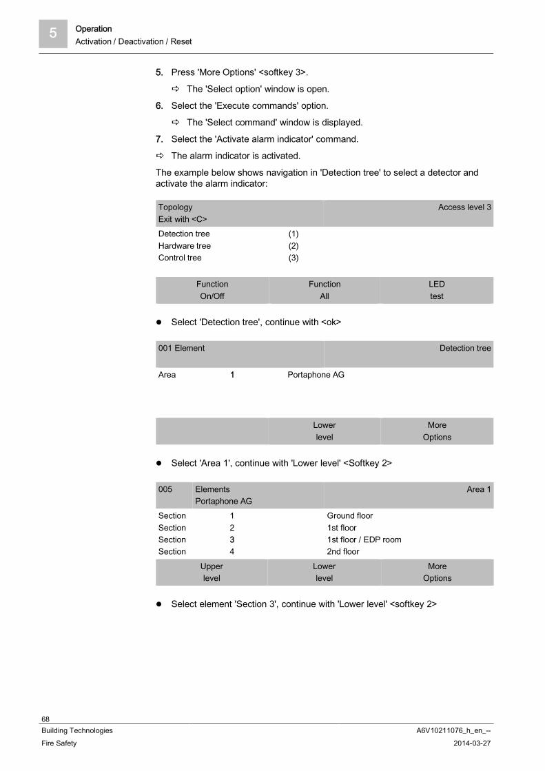
5 OperationActivation / Deactivation / Reset
68Building Technologies A6V10211076_h_en_--Fire Safety 2014-03-27
5. Press 'More Options' <softkey 3>.
The 'Select option' window is open.
6. Select the 'Execute commands' option.
The 'Select command' window is displayed.
7. Select the 'Activate alarm indicator' command.
The alarm indicator is activated.
The example below shows navigation in 'Detection tree' to select a detector andactivate the alarm indicator:
TopologyExit with <C>
Access level 3
Detection treeHardware treeControl tree
(1)(2)(3)
FunctionOn/Off
FunctionAll
LEDtest
Select 'Detection tree', continue with <ok>
001 Element Detection tree
Area 1 Portaphone AG
Lowerlevel
MoreOptions
Select 'Area 1', continue with 'Lower level' <Softkey 2>
005 ElementsPortaphone AG
Area 1
SectionSectionSectionSection
1234
Ground floor1st floor1st floor / EDP room2nd floor
Upperlevel
Lowerlevel
MoreOptions
Select element 'Section 3', continue with 'Lower level' <softkey 2>
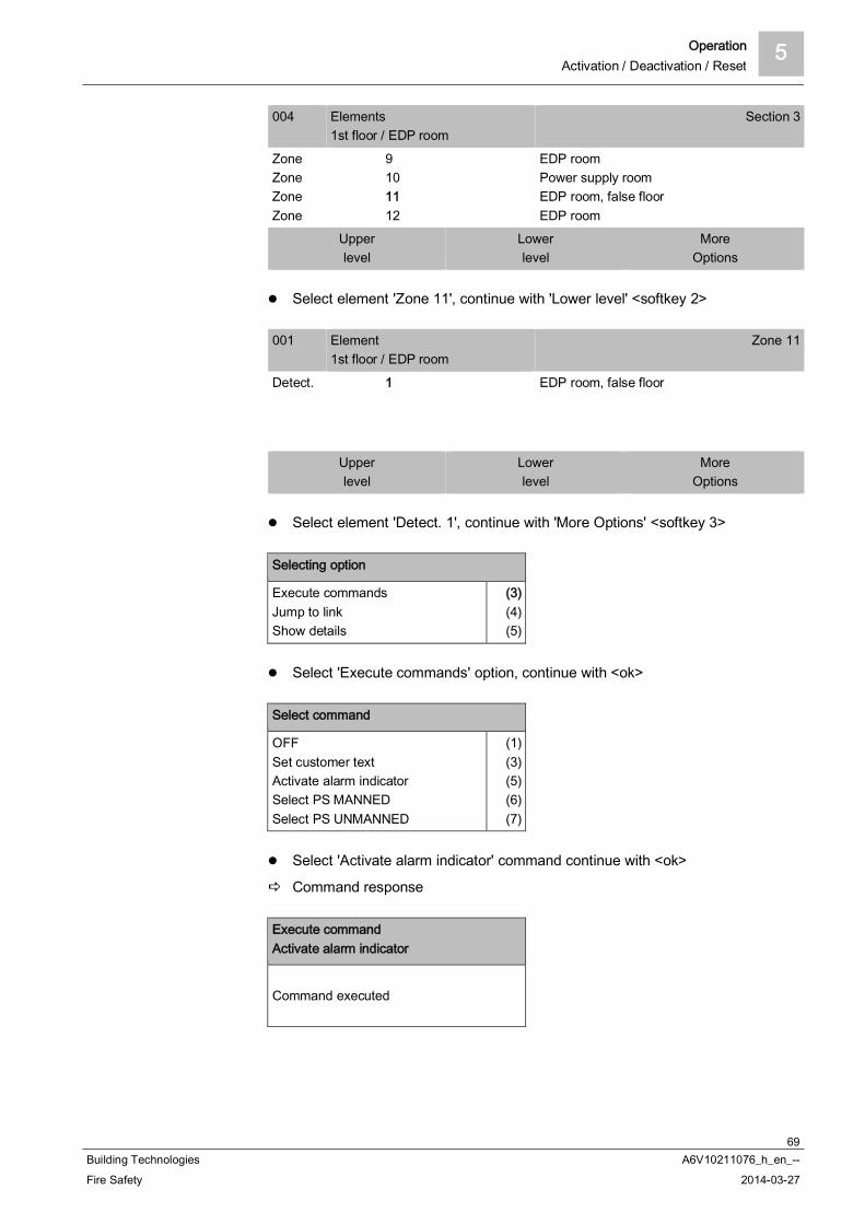
Operation 5Activation / Deactivation / Reset
69Building Technologies A6V10211076_h_en_--Fire Safety 2014-03-27
004 Elements1st floor / EDP room
Section 3
ZoneZoneZoneZone
9101112
EDP roomPower supply roomEDP room, false floorEDP room
Upperlevel
Lowerlevel
MoreOptions
Select element 'Zone 11', continue with 'Lower level' <softkey 2>
001 Element1st floor / EDP room
Zone 11
Detect. 1 EDP room, false floor
Upperlevel
Lowerlevel
MoreOptions
Select element 'Detect. 1', continue with 'More Options' <softkey 3>
Selecting option
Execute commandsJump to linkShow details
(3)(4)(5)
Select 'Execute commands' option, continue with <ok>
Select command
OFFSet customer textActivate alarm indicatorSelect PS MANNEDSelect PS UNMANNED
(1)(3)(5)(6)(7)
Select 'Activate alarm indicator' command continue with <ok>
Command response
Execute commandActivate alarm indicator
Command executed
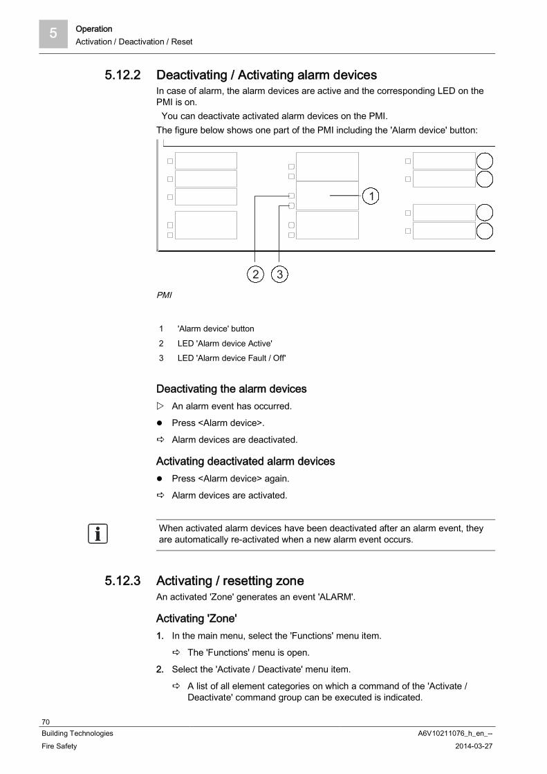
5 OperationActivation / Deactivation / Reset
70Building Technologies A6V10211076_h_en_--Fire Safety 2014-03-27
5.12.2 Deactivating / Activating alarm devicesIn case of alarm, the alarm devices are active and the corresponding LED on thePMI is on. You can deactivate activated alarm devices on the PMI.The figure below shows one part of the PMI including the 'Alarm device' button:
PMI
1 'Alarm device' button
2 LED 'Alarm device Active'3 LED 'Alarm device Fault / Off'
Deactivating the alarm devices An alarm event has occurred.
Press <Alarm device>.
Alarm devices are deactivated.
Activating deactivated alarm devices Press <Alarm device> again.
Alarm devices are activated.
When activated alarm devices have been deactivated after an alarm event, theyare automatically re-activated when a new alarm event occurs.
5.12.3 Activating / resetting zoneAn activated 'Zone' generates an event 'ALARM'.
Activating 'Zone'1. In the main menu, select the 'Functions' menu item.
The 'Functions' menu is open.
2. Select the 'Activate / Deactivate' menu item.
A list of all element categories on which a command of the 'Activate /Deactivate' command group can be executed is indicated.

Operation 5Activation / Deactivation / Reset
71Building Technologies A6V10211076_h_en_--Fire Safety 2014-03-27
3. Select the 'Zone' element category.
The 'Enter address' window is open.
4. Press <ok> without entering an address.
A list with all 'Zones' is open.
5. Select an 'Zone' and press <softkey 1>.
The 'Select command' window is open.
6. Select 'Activate'.
'Zone' is activated.
The window with the command response is open.
Example for the activation of a 'Zone'
FunctionsExit with <C>
Access level 2.2
On / OffTestActivate / DeactivateInformation
(1)(2)(3)(4)
ConfigurationMaintenanceAll functions
(5)(6)(7)
FunctionOn/Off
FunctionAll
LEDtest
Select 'Activate / Deactivate' function in the main menu, continue with <ok>
Selecting element category
AreaZoneSounderRT controlAlarming control group
(1)(2)(3)(4)(5)
Select 'Zone' element category, continue with <ok>
Enter address
Zone ---------Confirm with <ok>/Exit with <C>Delete with <Cursor up>
Press <ok> without entering an address
004 Zones
ZoneZoneZoneZone
1234
FSE Zone1Manual Zone 2
ExecuteCommands
Execute commandsTopology
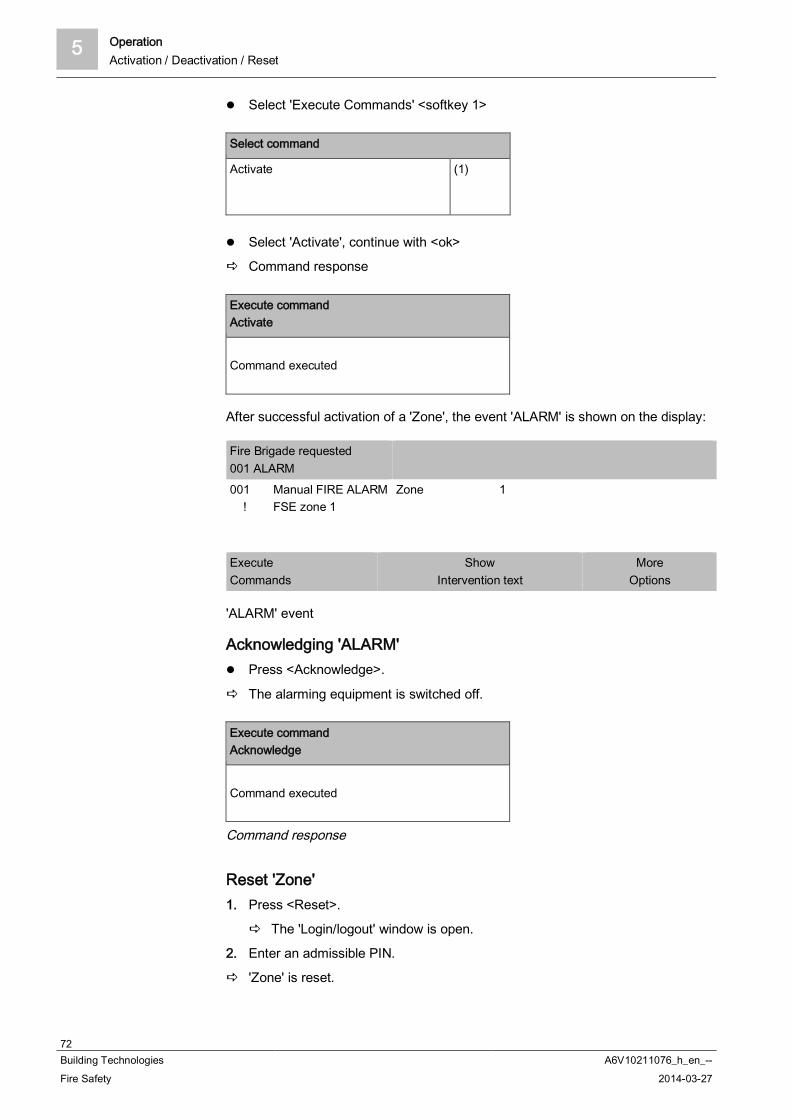
5 OperationActivation / Deactivation / Reset
72Building Technologies A6V10211076_h_en_--Fire Safety 2014-03-27
Select 'Execute Commands' <softkey 1>
Select command
Activate (1)
Select 'Activate', continue with <ok>
Command response
Execute commandActivate
Command executed
After successful activation of a 'Zone', the event 'ALARM' is shown on the display:
Fire Brigade requested001 ALARM001 !
Manual FIRE ALARMFSE zone 1
Zone 1
ExecuteCommands
ShowIntervention text
MoreOptions
'ALARM' event
Acknowledging 'ALARM' Press <Acknowledge>.
The alarming equipment is switched off.
Execute commandAcknowledge
Command executed
Command response
Reset 'Zone'1. Press <Reset>.
The 'Login/logout' window is open.
2. Enter an admissible PIN.
'Zone' is reset.

Operation 5Activation / Deactivation / Reset
73Building Technologies A6V10211076_h_en_--Fire Safety 2014-03-27
5.12.4 Activating / deactivating universal control
Activating a 'Fire control'1. In the main menu, select the 'Functions' menu item.
The 'Functions' menu is open.
2. Select the 'Activate / Deactivate' menu item.
A list of all element categories on which a command of the 'Activate /Deactivate' command group can be executed is indicated.
3. Select the 'Output Fire control' element category.
The 'Enter address' window is open.
4. Press <ok> without entering an address.
A list with all 'Fire controls' is open.
5. Select an 'Fire control' and press <softkey 1>.
The 'Select command' window is open.
6. Select 'Activate'.
'Fire control' is activated.
The window with the command response is open.
Example for the deactivation of a 'Fire control', in accordance withthe method outlined above:
FunctionsExit with <C>
Access level 2.1
On / OffTestActivate / DeactivateInformation
(1)(2)(3)(4)
ConfigurationMaintenanceAll functions
(5)(6)(7)
FunctionOn/Off
FunctionAll
LEDtest
Select 'Activate / Deactivate', continue with <ok>
Selecting element category
Fire control groupPhysical channelFire control groupOutput Fire controlRT channel
(7)(8)(9)
Select 'Output Fire control', continue with <ok>
Enter address
Fire ct 1--------OUTFire 1--Confirm with <ok>/Exit with <C>Delete with <Cursor up>

5 OperationActivation / Deactivation / Reset
74Building Technologies A6V10211076_h_en_--Fire Safety 2014-03-27
E.g. continue with <ok> without entering an address
009 OUTFire
OUTFireOUTFireOUTFireOUTFire
2121
Lakeside corridorMountain side corridorLakeside corridorElevator shaft 1st floor
ExecuteCommands
Execute commandsTopology
Select 'Execute Commands' <softkey 1>
Select command
OFFActivate
(1)(4)
Select 'Activate' command, continue with <ok>
Command response
Execute commandActivate
Command executed
Deactivating a 'Fire control'Proceed as with activating, but select the command 'Deactivate'.
5.12.5 Activating evac controls1. In the main menu, select the 'Functions' menu item.
The 'Functions' window is open.
2. Select the 'Activate / Deactivate' menu item.
A list of all element categories on which a command of the 'Activate /Deactivate' command group can be executed is indicated.
3. Select the 'Evac control group' element category.
The 'Enter address' window is open.
4. Press <ok> without entering an address.
A list with all 'Evac controls' is open if more than one Evac category hasbeen configured.
5. Select an 'Evac control group' and press <softkey 1>.
The 'Select command' window is open.
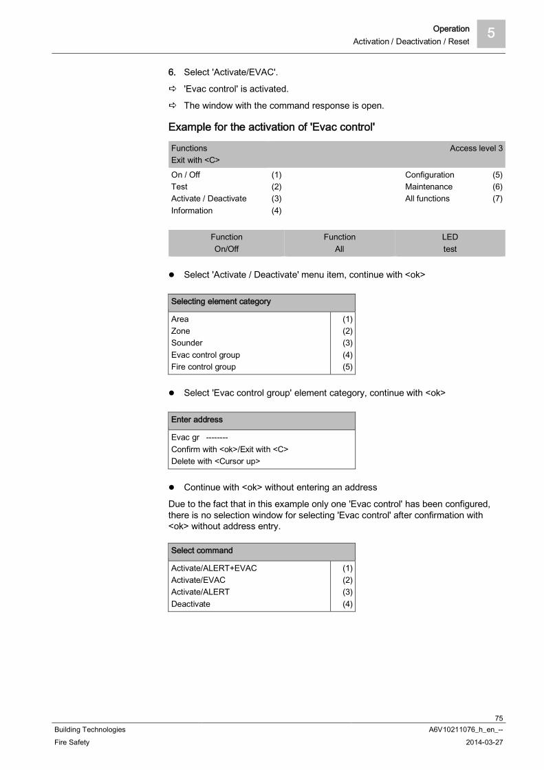
Operation 5Activation / Deactivation / Reset
75Building Technologies A6V10211076_h_en_--Fire Safety 2014-03-27
6. Select 'Activate/EVAC'.
'Evac control' is activated.
The window with the command response is open.
Example for the activation of 'Evac control'
FunctionsExit with <C>
Access level 3
On / OffTestActivate / DeactivateInformation
(1)(2)(3)(4)
ConfigurationMaintenanceAll functions
(5)(6)(7)
FunctionOn/Off
FunctionAll
LEDtest
Select 'Activate / Deactivate' menu item, continue with <ok>
Selecting element category
AreaZoneSounderEvac control groupFire control group
(1)(2)(3)(4)(5)
Select 'Evac control group' element category, continue with <ok>
Enter address
Evac gr --------Confirm with <ok>/Exit with <C>Delete with <Cursor up>
Continue with <ok> without entering an address
Due to the fact that in this example only one 'Evac control' has been configured,there is no selection window for selecting 'Evac control' after confirmation with<ok> without address entry.
Select command
Activate/ALERT+EVACActivate/EVACActivate/ALERTDeactivate
(1)(2)(3)(4)

5 OperationShow information
76Building Technologies A6V10211076_h_en_--Fire Safety 2014-03-27
Select 'Activate/EVAC' command continue with <ok>
Command response
Execute commandActivate/EVAC
Command executed
5.13 Show information
5.13.1 Polling alarm counters / remote transmissionsThe fire control panel has functions that count alarm events. The number of allalarms can be called up using alarm counter.There are three different types of alarm counters:
Every 'Area' automatically has the function of counting all alarms of therespective 'Area'.
Every 'RT control' automatically has the function of counting its respective ownactivation.
The 'Counter control' is freely configuraable and can count all alarms of the'Site', for example. The 'Counter control' is pre-configured as standard for somecountries, e.g., AT.
Polling the alarm counter for an 'Area'1. Press 'Functions' > 'All functions' in the main menu.
The 'Select element category' window is open.
2. Select the 'Area' element category.
The 'Enter address' window is open.
3. Press <ok> without entering an address.
A list with 'Areas' is opened.
4. Select a 'Area' and press <softkey 1> 'Execute commands'.
The 'Select command' window is open.
5. Select the 'Poll alarm counter' command.
The number of alarms that have been occurred is indicated.
Execute commandPoll alarm counter
Alarm counter value is: 3
Example with alarm counter value

Operation 5Polling reports
77Building Technologies A6V10211076_h_en_--Fire Safety 2014-03-27
Poll RT counter1. Press 'Functions' > 'All functions' in the main menu.
The 'Select element category' window is open.
2. Select the 'RT control' element category.
The 'Enter address' window is open.
3. Press <ok> without entering an address.
A list with all elements of the 'RT' type is open.
4. Select an element and press <softkey 1> 'Execute commands'.
The 'Select command' window is open.
5. Select the 'Poll RT counter' command.
The number of remote transmissions is shown.
Counter control DisplayingThe pre-configuration of the 'Counter control' parts list is country-specific.
1. Press 'Functions' > 'Information' in the main menu.
2. Select that 'Counter control' is displayed.
3. All results for the configured range for 'Counter control' are displayed.
5.14 Polling reportsYou can poll the following 'Reports' for the elements 'Reports', 'Station', 'Module', or'Line' in the 'Device' menu:
'Report SW version'/software version: Information on all firmware updates isdisplayed in the Report SW version system. There may be multiple softwareversions available for one element.
'Report HW version'/hardware version: Information is displayed on thehardware version, e.g., the hardware version of a detector.
Polling 'Reports' for the 'Station'1. Select 'Main menu' > 'Functions' > 'Reports'.
The 'Select element category' window is open.
2. Select 'Station'.
3. Enter the address of the 'Station' and confirm with <ok>.
- or
4. Continue without entering an address and confirm with <ok>.
The 'Select command' window is open.
5. To display the software version, select 'Report SW version'.
- or
6. To display the hardware version, select 'Report HW version'.
The selected 'Reports' are displayed.
7. Optional: To print out the 'Reports', select 'Print report'.
5 OperationEntering the configuration
78Building Technologies A6V10211076_h_en_--Fire Safety 2014-03-27
Polling 'Reports' for individual 'Modules'1. Select 'Main menu' > 'Functions' > 'Reports'.
The 'Select element category' window is open.
2. Select 'Module'.
You then have two options for selecting a 'Module': Selecting 'Module' with an address Selecting 'Module' from a list (without entering an address)
Selecting 'Module' with an address1. Enter the address of the 'Station' and the 'Module' and confirm with <ok>.
The 'Select command' window is open.
2. To display the software version, select 'Report SW version'.
- or
3. To display the hardware version, select 'Report HW version'.
The selected 'Reports' are displayed.
4. Optional: To print out the 'Reports', select 'Print report'.
Selecting a 'Module' from a list1. Continue without entering an address and confirm with <ok>.
The list of all 'Modules' is displayed.
2. Select a 'Module'.
3. Press the 'Execute Commands' softkey.
The 'Select command' window is open.
4. To display the software version, select 'Report SW version'.
- or
5. To display the hardware version, select 'Report HW version'.
The selected 'Reports' are displayed.
6. Optional: To print out the 'Reports', select 'Print report'.
5.15 Entering the configurationFor example you can undertake the following settings in the menu 'Configuration':
Switch 'Manned operation' / 'Unmanned operation' Set times for 'Unmanned operation' Set parameter sets for 'Manned operation' and 'Unmanned operation' Set customer text
Configuring the installation1. In the main menu, select the 'Functions' menu item.
The 'Functions' menu is open.
2. Select the 'Configuration' menu item.
A list of all element categories on which a command of the 'Configuration'command group can be executed is indicated.

Operation 5Auto-configure station
79Building Technologies A6V10211076_h_en_--Fire Safety 2014-03-27
3. Select the element category you want to configure.
The 'Enter address' window is open.
4. Press <ok> without entering an address.
A list with all elements is open.
5. Select an element and press <Softkey 1>.
The 'Select command' window is open.
6. Select a command.
The command is executed.
5.16 Auto-configure stationWith the 'Auto-configure station' function you can commission a newly installed'Station' immediately and without any additional settings.
NOTICE
Overwriting an existing configurationAn existing customer-specific configuration is lost.
First save an existing customer-specific configuration.
The 'Auto-configure station' process takes a few minutes, depending on theinstallation size.
1. In the main menu, select the 'Topology' menu item.
The 'Topology' menu is open.
2. Select 'Hardware tree'.
A list with all 'Stations' is displayed.
3. Select a 'Station'.
4. Press 'More options'.
The 'Select option' window is open.
5. Select 'Auto-configure station'.
'Station' is auto-configured.

5 OperationAuto-configure line
80Building Technologies A6V10211076_h_en_--Fire Safety 2014-03-27
5.17 Auto-configure lineThe 'Line' element category in the 'Maintenance' menu facilitates the reading-in ofthe current topology, for example. This creates part of the elements in the 'Line'.
NOTICE
Overwriting an existing configurationParts of an existing customer-specific configuration are lost.
First save an existing customer-specific configuration.
Auto-configuring a line:1. In the main menu, select the 'Topology' menu item.
The 'Topology' window is open.
2. Select 'Hardware tree'.
The 'Element' window is open.
3. Select a 'Station' and press the 'Lower level' <softkey>.
The elements of 'Station' are displayed.
4. Select the corresponding 'C-NET line card (onboard/FCL2001)' module andpress the 'Lower level' <softkey>.
All lines of 'C-NET line card (onboard/FCL2001)' are indicated.
5. Select a line and press 'More Options' <softkey>.
The 'Select option' window is open.
6. Select 'Execute commands' and confirm with <ok>.
The window including the possible commands is displayed.
7. Select the 'Auto-configure line' command and confirm with <ok>.
The line is auto-configured.
Example of auto-configuration
Main menuExit with <C>
Access level 3
Message summaryFunctionsFavoritesTopology
(1)(2)(3)(4)
Element searchEvent memoryLogin/logoutSettings/administration
(5)(6)(7)(8)
FunctionOn/Off
FunctionAll
LEDtest
Select 'Topology', continue with <ok>

Operation 5Auto-configure line
81Building Technologies A6V10211076_h_en_--Fire Safety 2014-03-27
TopologyExit with <C>
Access level 3
Detection treeHardware treeControl tree
(1)(2)(3)
FunctionOn/Off
FunctionAll
LEDtest
Select 'Hardware tree', continue with <ok>
001 Element Hardware tree
Station 1 Main building
Lowerlevel
MoreOptions
Select 'Station 1', continue with 'Lower level' <softkey 2>
005FC2020
ElementsMain building
Station 1
ModuleModuleModuleModule
1234
Onboard I/OsC-NET line card (onboard/FCL2001)C-NET line card (onboard/FCL2001)Communication interfaces
Upperlevel
Lowerlevel
MoreOptions
Select 'Module 2', continue with 'Lower level' <softkey 2>
007 ElementsC-NET line card (onboard/FCL2001)
Module 2
LineLineLineLine
1212231
LineLineLineLine
Upperlevel
Lowerlevel
MoreOptions
Select 'Line 1', continue with 'More Options' <softkey 3>
Selecting option
Execute commandsShow details
(3)(5)
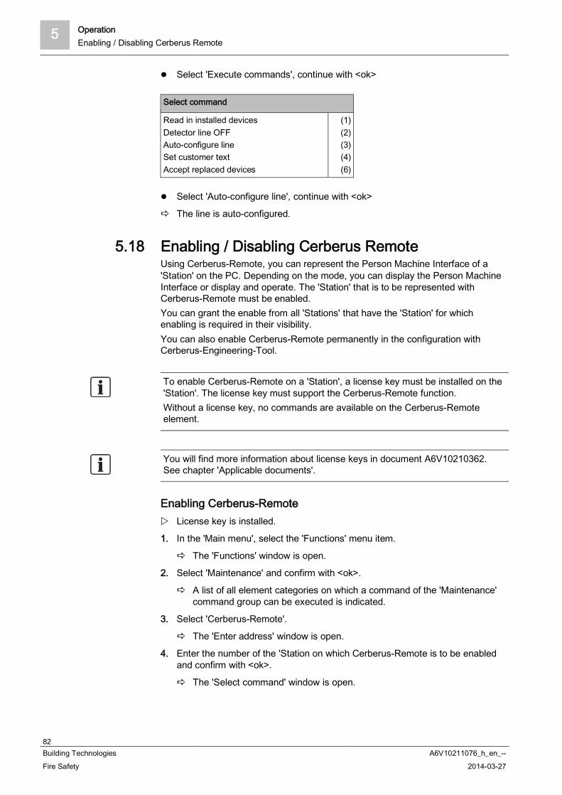
5 OperationEnabling / Disabling Cerberus Remote
82Building Technologies A6V10211076_h_en_--Fire Safety 2014-03-27
Select 'Execute commands', continue with <ok>
Select command
Read in installed devicesDetector line OFFAuto-configure lineSet customer textAccept replaced devices
(1)(2)(3)(4)(6)
Select 'Auto-configure line', continue with <ok>
The line is auto-configured.
5.18 Enabling / Disabling Cerberus RemoteUsing Cerberus-Remote, you can represent the Person Machine Interface of a'Station' on the PC. Depending on the mode, you can display the Person MachineInterface or display and operate. The 'Station' that is to be represented withCerberus-Remote must be enabled.You can grant the enable from all 'Stations' that have the 'Station' for whichenabling is required in their visibility.You can also enable Cerberus-Remote permanently in the configuration withCerberus-Engineering-Tool.
To enable Cerberus-Remote on a 'Station', a license key must be installed on the'Station'. The license key must support the Cerberus-Remote function.Without a license key, no commands are available on the Cerberus-Remoteelement.
You will find more information about license keys in document A6V10210362.See chapter 'Applicable documents'.
Enabling Cerberus-Remote License key is installed.
1. In the 'Main menu', select the 'Functions' menu item.
The 'Functions' window is open.
2. Select 'Maintenance' and confirm with <ok>.
A list of all element categories on which a command of the 'Maintenance'command group can be executed is indicated.
3. Select 'Cerberus-Remote'.
The 'Enter address' window is open.
4. Enter the number of the 'Station on which Cerberus-Remote is to be enabledand confirm with <ok>.
The 'Select command' window is open.

Operation 5Enabling / Disabling Cerberus Remote
83Building Technologies A6V10211076_h_en_--Fire Safety 2014-03-27
5. Select the 'Enable full access' command and confirm with <ok>.
Enabling for viewing and operating the 'Station' with Cerberus-Remote isgranted.
or
Select the 'Enable view access' command and confirm with <ok>.
Enabling for viewing the 'Station' with Cerberus-Remote is granted.
The 'Enable full access' and 'Enable view access' commands cannot be selectedwhen enabling has already been granted. For the purpose of disabling Cerberus-Remote, the 'Disable access' command is available instead in the commandsection.
Disabling Cerberus-RemoteIf Cerberus-Remote is enabled but there is no link to Cerberus-Remote, you candisable the enable with the 'Disable access' command. Proceed as describedabove and select the corresponding command.When Cerberus-Remote is enabled for operation and the connection with theCerberus-Remote has been established, each operating attempt on the 'Station'opens the following window:
Window to abort the connection with Cerberus-Remote
Cerberus-Rem. operation
Abort Cerberus-Rem. connect. Exit with <C> Confirm with <ok>
Press <ok>
Connection with Cerberus-Remote is broken.
Enabling for Cerberus-Remote is disabled.

5 OperationConnecting Cerberus Remote
84Building Technologies A6V10211076_h_en_--Fire Safety 2014-03-27
5.19 Connecting Cerberus Remote
Cerberus-Remote can only ever be connected with one 'Station' at a time. Theconnection can be established locally or via the 'Global Access Point' (GAP). Forthis purpose, there must be a license key installed in the 'Station' that is to bedisplayed with Cerberus-Remote. The license key must support the Cerberus-Remote function.
Cerberus-Remote has the same visibility as the connected 'Station'. You can useCerberus-Remote in a fire detection installation with networked 'Stations' to gainglobal visibility. Just one license key is needed for this per network if the licensekey is installed in a 'Station' with global visibility.
You will find more information about license keys in document A6V10210362.See chapter 'Applicable documents'.
The possible 'Enable full access' or 'Enable view access' operation modes must beenabled before connecting to the 'Station'. The possible operation modes can alsobe permanently enabled in the configuration with Cerberus-Engineering-Tool.
Establishing connection1. Select in Cerberus-Engineering-Tool the task card 'Cerberus-Remote'.
2. Select 'Cerberus-Remote' > 'Connect' from the menu bar.
A window with the selection of the connection type is indicated.
3. Select the required type of connection and confirm with 'OK'.
A window with the list of all 'Stations' of the 'Site' is indicated.
4. Highlight the corresponding 'Station'.
5. Enter your PIN.
6. Click on 'OK'.
The connection is established.
The connection with a 'Station' is shown by the Person Machine Interface(display, LEDs, keys) transmitted.The 'Cerberus-Remote access' operation mode is indicated by a red framearound the Person Machine Interface.An enable granted for Cerberus-Remote is retained when a 'Station' restarted.

Operation 5Setting up Cerberus Remote link with integrated IP
85Building Technologies A6V10211076_h_en_--Fire Safety 2014-03-27
5.20 Setting up Cerberus Remote link with integrated IPSituation and motivation
In addition to local connection, 'Cerberus-Remote' can be used to establish aconnection to a 'Station' using a network and IP address.
You might want to view various 'Stations' with 'Cerberus-Remote'. We would recommend avoiding the repeated entering of IP addresses when
repeatedly establishing connections to 'Stations'.
Option Execution of 'Cerberus-Remote' with additional parameters (IP address and
PIN). Save modified program execution as link.
Procedure Start 'Cerberus-Remote' as own application (FX2020) and not from the
corresponding register in 'Cerberus-Engineering-Tool' (FX2030).
1. Right-click on link in 'Start' > 'Siemens' > 'FX2020' > … to go to the executable'Cerberus-Remote' file and copy the link to the clipboard or an editor.
2. Add following parameters to program execution:
- IP address for GAP.- Host ID for 'C-WEB'-'Station' to be viewed with 'Cerberus-Remote'.- PIN for 'Access level' 3.
Modified program execution with integrated IP is created.
Example:C:\Program Files\Siemens\F-FX2020\XL_en_1-V2.1>F-FXS2009.exe"-visualizer ip=192.168.200.1 host=1 pin=0000
Test program execution command using 'Start' > 'Execute'
Creating link on desktop1. Right-click on desktop and select 'New' > 'Link'.
2. Copy tested, modified program execution command to input field.
3. Confirm with 'Continue' and give link a name.
4. Click on 'Finish'
Link with modified program execution and integrated IP is set up.
5.21 Operating Cerberus RemoteCerberus-Remote You can operate with the mouse or with the PC keyboard.The operating functions of the keys shown are identical with those on the Station'.

5 OperationSpecifying the operation mode for Cerberus Mobile
86Building Technologies A6V10211076_h_en_--Fire Safety 2014-03-27
5.22 Specifying the operation mode for Cerberus MobileSpecification of operation mode on the 'Station'
The 'Cerberus Mobile' element must be configured manually in Station' for a'Cerberus-Engineering-Tool'.
You can configure a permanent operation mode for 'Cerberus-Engineering-Tool'in 'Cerberus Mobile'. If 'Permanent Cerberus Mobile access' is configured, you donot need to define the operation mode on the 'Station'.
1. In the 'Main menu', select the 'Topology' menu item.
2. Select the 'Hardware tree' subtree.
3. Navigate to 'Station' > 'Mobile'.
4. Press the 'More Options' softkey.
5. Select 'Execute Commands' and confirm with <ok>.
The 'Select command' window is open.
6. Select the 'Enable full access' or 'Enable view access' command and confirmwith <ok>.
The operation mode for 'Cerberus Mobile' is now specified.
Deactivation of operation mode on the 'Station'
If you have permanently configured the operation mode in 'Cerberus-Engineering-Tool' you must deactivate the operation mode in 'Cerberus-Engineering-Tool'.
Proceed as for 'Specification of operation mode on the 'Station'' and select theSelect command' command in the 'Disable access' window.
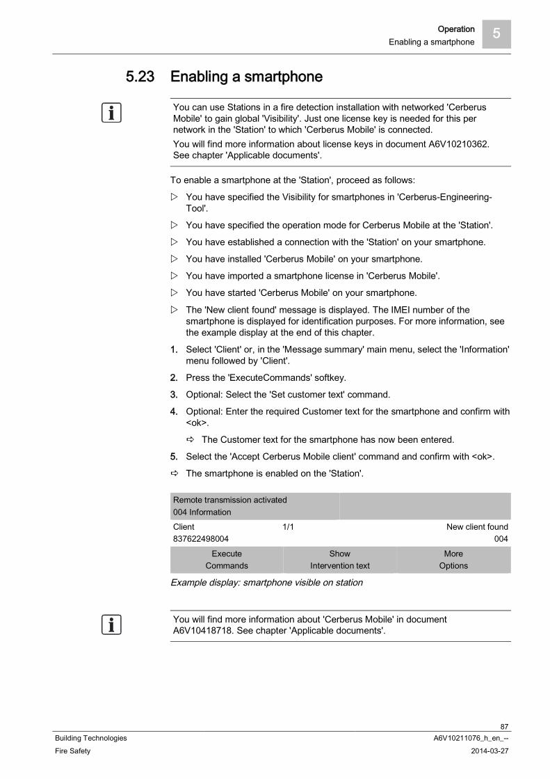
Operation 5Enabling a smartphone
87Building Technologies A6V10211076_h_en_--Fire Safety 2014-03-27
5.23 Enabling a smartphone
You can use Stations in a fire detection installation with networked 'CerberusMobile' to gain global 'Visibility'. Just one license key is needed for this pernetwork in the 'Station' to which 'Cerberus Mobile' is connected.You will find more information about license keys in document A6V10210362.See chapter 'Applicable documents'.
To enable a smartphone at the 'Station', proceed as follows:
You have specified the Visibility for smartphones in 'Cerberus-Engineering-Tool'.
You have specified the operation mode for Cerberus Mobile at the 'Station'.
You have established a connection with the 'Station' on your smartphone.
You have installed 'Cerberus Mobile' on your smartphone.
You have imported a smartphone license in 'Cerberus Mobile'.
You have started 'Cerberus Mobile' on your smartphone.
The 'New client found' message is displayed. The IMEI number of thesmartphone is displayed for identification purposes. For more information, seethe example display at the end of this chapter.
1. Select 'Client' or, in the 'Message summary' main menu, select the 'Information'menu followed by 'Client'.
2. Press the 'ExecuteCommands' softkey.
3. Optional: Select the 'Set customer text' command.
4. Optional: Enter the required Customer text for the smartphone and confirm with<ok>.
The Customer text for the smartphone has now been entered.
5. Select the 'Accept Cerberus Mobile client' command and confirm with <ok>.
The smartphone is enabled on the 'Station'.
Remote transmission activated004 InformationClient837622498004
1/1 New client found004
ExecuteCommands
ShowIntervention text
MoreOptions
Example display: smartphone visible on station
You will find more information about 'Cerberus Mobile' in documentA6V10418718. See chapter 'Applicable documents'.

5 OperationRemoving a smartphone
88Building Technologies A6V10211076_h_en_--Fire Safety 2014-03-27
5.24 Removing a smartphoneTo remove a smartphone from a 'Station', proceed as follows:
1. In the main menu, select the 'Topology' menu item.
The three partial trees of the topology tree are indicated.
2. Select 'Hardware tree'.
3. Select the 'Station'.
4. Select 'Mobile'.
5. Select the smartphone.
6. Press the 'Execute Commands' softkey.
7. Select the 'Remove Cerberus Mobile client' command and confirm with <ok>.
The smartphone is removed at the 'Station'.
5.25 Polling / Deleting the event memory
As an alternative to the indication of the event memory on the 'Station', the data ofthe event memory may also be transmitted to a PC in a standard format. To doso, a PC with a configuration tool must be connected to the 'Station'.You will find more information in document 'A6V10210424'.
Polling the event memory1. In the main menu, select the 'Functions' menu item.
The 'Functions' menu is open.
2. Select the 'Event memory' menu item.
The 'Select station' window is open.
3. Select the 'Station' you want.
The list of all events for 'Station' is displayed.
Using the softkeys 1-2, you can now filter by category, or date/time.
Navigating in the event memoryEntering a 3-digit number in the event memory (e.g.: 1, 132, 500) and confirmingby pressing <ok> takes you straight to the corresponding entry.
Deleting the event memory1. In the main menu, select the 'Functions' menu item.
The 'Functions' window is open.
2. Select 'Maintenance' and confirm with <ok>.
A list of all element categories on which a command of the 'Maintenance'command group can be executed is indicated.
3. Select 'Station'.
The 'Enter address' window is open.
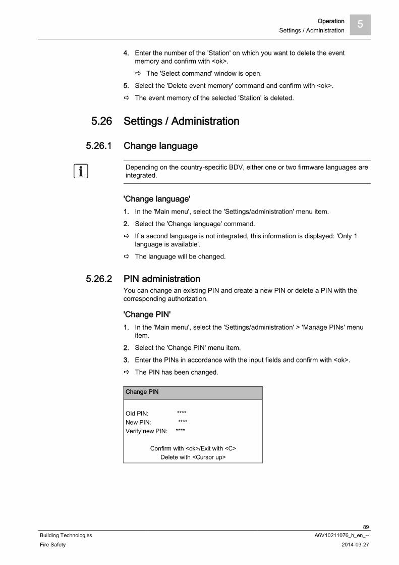
Operation 5Settings / Administration
89Building Technologies A6V10211076_h_en_--Fire Safety 2014-03-27
4. Enter the number of the 'Station' on which you want to delete the eventmemory and confirm with <ok>.
The 'Select command' window is open.
5. Select the 'Delete event memory' command and confirm with <ok>.
The event memory of the selected 'Station' is deleted.
5.26 Settings / Administration
5.26.1 Change language
Depending on the country-specific BDV, either one or two firmware languages areintegrated.
'Change language'1. In the 'Main menu', select the 'Settings/administration' menu item.
2. Select the 'Change language' command.
If a second language is not integrated, this information is displayed: 'Only 1language is available'.
The language will be changed.
5.26.2 PIN administrationYou can change an existing PIN and create a new PIN or delete a PIN with thecorresponding authorization.
'Change PIN'1. In the 'Main menu', select the 'Settings/administration' > 'Manage PINs' menu
item.
2. Select the 'Change PIN' menu item.
3. Enter the PINs in accordance with the input fields and confirm with <ok>.
The PIN has been changed.
Change PIN
Old PIN: ****New PIN: ****Verify new PIN: ****
Confirm with <ok>/Exit with <C>Delete with <Cursor up>

5 OperationSettings / Administration
90Building Technologies A6V10211076_h_en_--Fire Safety 2014-03-27
'Create PIN' You have the required authorization level.
1. In the 'Main menu', select the 'Settings/administration' > 'Manage PINs' menuitem.
2. Select the 'Create PIN' menu item.
3. Enter an admissible access level.
4. Enter the PIN in accordance with the input fields and confirm with <ok>.
A new PIN has been created.
Create PIN
Access level: __Enter PIN: ****Verify PIN: ****
Confirm with <ok>/Exit with <C>Delete with <Cursor up>
'Delete PIN' PIN is present.
You have the required authorization level.
1. In the 'Main menu', select the 'Settings/administration' > 'Manage PINs' menuitem.
2. Select the 'Delete PIN' menu item.
3. Enter the PIN in accordance with the input fields and confirm with <ok>.
PIN has been deleted.
Delete PIN
Enter PIN: ****Verify PIN: ****
Confirm with <ok>/Exit with <C>Delete with <Cursor up>
Operation 5Settings / Administration
91Building Technologies A6V10211076_h_en_--Fire Safety 2014-03-27
5.26.3 Setting the buzzer volumeYou can set the volume of the 'Station' buzzer on four levels or switch it off.
NOTICE
Buzzer volume too lowNon-compliance with EN54-2 Para 12.10.2
Set the buzzer volume to the maximum.
As per EN54-2, the minimum sound level at a distance of 1 m must reach thefollowing values, measured under open air conditions:-60 dB (A) for announcing fire alarm signals-50 dB (A) for announcing fault messages
'Set buzzer volume'1. In the 'Main menu', select the 'Settings/administration' menu item.
2. Select the 'Set buzzer volume' menu item.
The 'Set buzzer volume' window is open.
3. Select the desired settings in the list.
The buzzer volume has been set.
5.26.4 Adjusting the display brightnessYou can set the display brightness on five levels between 'Off', 25% and 100%.
'Change display brightness'1. In the 'Main menu', select the 'Settings/administration' menu item.
2. Select the 'Display settings' menu item.
The 'Display settings' window is open.
3. Select 'Change display brightness'.
The window for the adjustment is open.
4. Select the desired settings in the list.
The display brightness has been adjusted.
5.26.5 Setting time and dateYou will have to reset the clock if the fire control panel has been de-energized. In countries with central European summer time (CEST), the system clockautomatically switches between daylight savings time and regular time.
'Enter date / time'1. In the 'Main menu', select the 'Settings/administration' menu item.
2. Select the 'System commands' menu item.
The 'System commands' window is open.
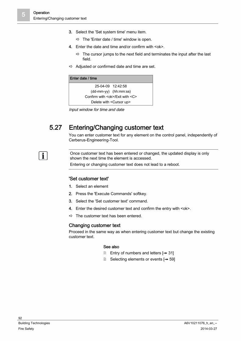
5 OperationEntering/Changing customer text
92Building Technologies A6V10211076_h_en_--Fire Safety 2014-03-27
3. Select the 'Set system time' menu item.
The 'Enter date / time' window is open.
4. Enter the date and time and/or confirm with <ok>.
The cursor jumps to the next field and terminates the input after the lastfield.
Adjusted or confirmed date and time are set.
Enter date / time
25-04-09 12:42:58(dd-mm-yy) (hh:mm:ss)
Confirm with <ok>/Exit with <C>Delete with <Cursor up>
Input window for time and date
5.27 Entering/Changing customer textYou can enter customer text for any element on the control panel, independently ofCerberus-Engineering-Tool.
Once customer text has been entered or changed, the updated display is onlyshown the next time the element is accessed.Entering or changing customer text does not lead to a reboot.
'Set customer text'1. Select an element
2. Press the 'Execute Commands' softkey.
3. Select the 'Set customer text' command.
4. Enter the desired customer text and confirm the entry with <ok>.
The customer text has been entered.
Changing customer textProceed in the same way as when entering customer text but change the existingcustomer text.
See also Entry of numbers and letters [ 31] Selecting elements or events [ 59]
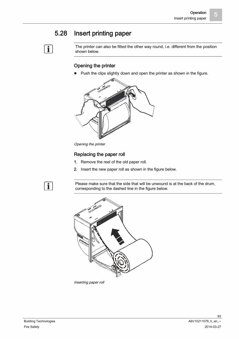
Operation 5Insert printing paper
93Building Technologies A6V10211076_h_en_--Fire Safety 2014-03-27
5.28 Insert printing paper
The printer can also be fitted the other way round, i.e. different from the positionshown below.
Opening the printer Push the clips slightly down and open the printer as shown in the figure.
Opening the printer
Replacing the paper roll1. Remove the reel of the old paper roll.
2. Insert the new paper roll as shown in the figure below.
Please make sure that the side that will be unwound is at the back of the drum,corresponding to the dashed line in the figure below.
Inserting paper roll

5 OperationInsert printing paper
94Building Technologies A6V10211076_h_en_--Fire Safety 2014-03-27
Closing printer1. Pull some of the paper out of the printer.
2. Hold the paper end upwards.
3. Close the printer by holding the bracket upwards until the clips audibly engage.
The printer is ready.
Closing printer
Printer is ready
Operation 5Switching off the printer
95Building Technologies A6V10211076_h_en_--Fire Safety 2014-03-27
5.29 Switching off the printerYou can switch off the printer with a command.
Switching off the printer1. Press <Menu>.
The main menu is open.
2. Press 'Function On/Off' <softkey 1>.
The window with element categories and elements is indicated.
3. Select the 'Printer' element and press <softkey 1>.
The window with the command selection is open.
4. Select the 'OFF' command and confirm with 'ok'.
The printer is switched off.
To switch on a printer that has been switched off, proceed as when switching theprinter off but select the 'ON' command.
5.30 Show versionThe version of the 'Station' and the configuration data are available in 'Hardwaretree'.
Version indication1. In the main menu, select the 'Topology' menu item.
The three partial trees of the topology tree are indicated.
2. Select 'Hardware tree'.
3. Select the 'Station'.
4. Press the 'More Options' softkey.
The 'Select option' window is open.
5. Select 'Show details'.
The version of the 'Station' and configuration data are indicated.
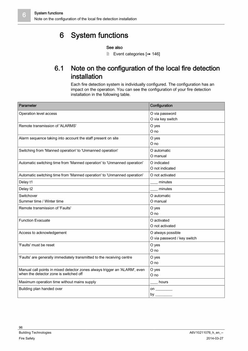
6 System functionsNote on the configuration of the local fire detection installation
96Building Technologies A6V10211076_h_en_--Fire Safety 2014-03-27
6 System functionsSee also
Event categories [ 146]
6.1 Note on the configuration of the local fire detectioninstallationEach fire detection system is individually configured. The configuration has animpact on the operation. You can see the configuration of your fire detectioninstallation in the following table.
Parameter Configuration
Operation level access O via passwordO via key switch
Remote transmission of 'ALARMS' O yesO no
Alarm sequence taking into account the staff present on site O yesO no
Switching from 'Manned operation' to 'Unmanned operation' O automaticO manual
Automatic switching time from 'Manned operation' to 'Unmanned operation' O indicatedO not indicated
Automatic switching time from 'Manned operation' to 'Unmanned operation' O not activated
Delay t1 ____ minutes
Delay t2 ____ minutes
SwitchoverSummer time / Winter time
O automaticO manual
Remote transmission of 'Faults' O yesO no
Function Evacuate O activatedO not activated
Access to acknowledgement O always possibleO via password / key switch
'Faults' must be reset O yesO no
'Faults' are generally immediately transmitted to the receiving centre O yesO no
Manual call points in mixed detector zones always trigger an 'ALARM', evenwhen the detector zone is switched off
O yesO no
Maximum operation time without mains supply ____ hours
Building plan handed over on _________by _________
System functions 6Operating condition
97Building Technologies A6V10211076_h_en_--Fire Safety 2014-03-27
6.2 Operating conditionA fire detection installation is ready for operation when the fire control panel issupplied with energy and no other operation condition is indicated.As soon as an event occurs in the 'Station' which deviates from operationalreadiness, this event is indicated and the 'Station' changes to the conditioncorresponding to the type of event.'Station' may be in several conditions simultaneously:
'ALARM' (fire detection condition) 'FAULT' (fault message condition) 'ISOLATION' (isolation condition) 'DETECTOR TEST' (test status) Normal operation (operational readiness)
Indication of the operating condition The operating condition is indicated on the PMI:
– Visually and acoustically by LEDs, buzzers and on the display.
6.3 Operation modesThe fire detection installation has the following operation modes:
Normal operation– 'Manned operation'– 'Unmanned operation'
Test 'Isolation'
– ' --Renovation mode'
6.3.1 Normal operationIn normal operation 'ALARMS' are evaluated and processed in accordance with the'Manned operation' or 'Unmanned operation' operation mode.
Normal operation is described in the following: The detectors are set to normal sensitivity level, in accordance with the
parameter in account. The fire detection installation is ready to receive danger messages ('ALARMS')
and fault messages. The 'System On' LED lights up.
In normal operation the fire detection installation may be in 'Manned operation' or'Unmanned operation' operation mode. In the 'Manned operation' operation modethe 'Unmanned operation' LED is on.
'Manned operation'In the 'Manned operation' operation mode, events can be processed via 'AVC' or'IC'.The remote transmission of an 'ALARM' may be delayed, for example, and anoperator may verify 'ALARMS' or 'Faults' that have occurred.
6 System functionsOperation modes
98Building Technologies A6V10211076_h_en_--Fire Safety 2014-03-27
'Unmanned operation'In 'Unmanned operation' operation mode events are directly handled in accordancewith the configuration, without taking into account the 'AVC' or 'IC'.This means e.g. that remote transmission of an 'ALARM' is effected without delay.Global alarming is activated immediately.
6.3.2 TestFS720 offers various test functions for efficient testing of instruments and logicalfunctions. Some test methods can be combined, others have to be carried outindividually.The fire detection installation is in 'Test' operating mode if one of the following testmodes is activated:
'Detector test' 'Walk test' 'Control test' 'Installation test' Test variants
See also Testing [ 64]
6.3.3 IsolationYou can switch off 'Zones' with automatic or non-automatic detectors in specialsituations, e.g. during construction work.When parts of the fire detection installation are switched off, the fire detectioninstallation is in 'ISOLATION' condition and operating mode.The 'ISOLATION' LED on the Person Machine Interface is on.In 'ISOLATION' operating mode neither 'ALARMS' nor 'Faults' from the parts thathave been switched off can be evaluated.
You can set isolations with or without a time limit.
See also Switching off / Switching on [ 36]
6.3.4 RenovationIn ' --Renovation mode' operating mode the detector parameter sets are changedas follows:
No evaluation possible by the optical part of the detector. A static evaluation by the thermal part of the detector is possible, however,
without the evaluation of the temperature difference.
The 'ISOLATION' LED on the PMI is on as soon as a part of the installation hasbeen set to ' --Renovation mode'.

System functions 6Access level and access rights
99Building Technologies A6V10211076_h_en_--Fire Safety 2014-03-27
6.4 Access level and access rights'Station' is protected against unauthorized operation by the following access levels:
Access level Access rights Functions and access rights
1 Everybody 'Acknowledge' and scrolling
2.1 Operator 1 Limited access rights (e.g. janitor)
2.2 Operator 2 Extended access rights (e.g. safety and securitymanager)
3 Service technician All access rights (for service technicians)
On access level 1 the most important commands can be entered in case ofalarm.
Other commands or the configuration of the 'Station' are possible starting withaccess level 2.1.
Access levels are enabled by the PIN input dialog or the key switch. Each PIN is assigned to an access level. Menu entries, functions and favorites that are not accessible on an access level
are hidden.
A list of all commands and the required access levels can be found in thecorresponding chapter.
The following table shows examples of main menu items and the access levelsneeded for executionMain menu item Required access level
'Message summary' 1
'Functions' 1, 2.1, 2.2, 3, depending on the function
'Favorites' 1, 2.1, 2.2, 3, depending on the favorite
'Topology' 1
'Element search' 1
'Event memory' 2.1
'Login/logout' 1
'Settings/administration' 3
Comparison of the access level release with key switch or PIN: The key switch takes priority over the PIN entry. When the key switch is in position 'On', the set access level cannot be changed
by a PIN entry. When the key switch is turned to position 'On' during the PIN entry, the PIN
entry dialog is closed.
When the key switch is in position 'On', the logout timeout function is deactivated.
See also Logout timeout [ 100] Commands with required access levels [ 102]

6 System functionsVisibility
100Building Technologies A6V10211076_h_en_--Fire Safety 2014-03-27
6.4.1 PIN input dialogThe 'Login/logout' main menu item opens the PIN input dialog. The access level inaccount is released by entering a valid PIN.
The PIN input dialog is indicated automatically if the activation of a button on thePMI requires a higher access level.
6.4.2 Logout timeoutThe 'Station' is provided with a time control function for the operation.The operation enable for an 'Access level' expires after a configurable period oftime has passed since the last entry.
See also Log in / Change access level [ 49]
6.4.3 Cerberus Remote enablingThe corresponding chapter describes how to enable Cerberus-Remote.
See also Enabling / Disabling Cerberus Remote [ 82]
6.5 VisibilitySeveral fire control panels and fire terminals ('Stations') can be integrated into a firedetection installation. The visibility defines which part of a fire detection installationon 'Stations' is visible and can be operated.
The visibility is configured in Cerberus-Engineering-Tool.
The visibility for a fire control panel can be configured in the following topologylevels of a fire detection installation:
'Site' 'Station' 'Area'
The visibility for this 'Station' is configured by selecting and assigning eventcategories from the topology to the visibility for this 'Station'.For example, all the 'ALARMS' for the 'Site' or just the 'Faults' for the 'Area' of a'Station' are indicated.Two other modes are available for configuring the visibility:
'PMI standby visibility' 'PMI expanded visibility'
See also Changing visibility [ 52] Event categories [ 146]

System functions 6Sabotage ALARM [DE]
101Building Technologies A6V10211076_h_en_--Fire Safety 2014-03-27
6.5.1 Standby visibilityThe 'Station' with the 'PMI standby visibility' configuration monitors one or moreother 'Stations'or a management station in the configured visibility.
When the fire detection installation is in normal operating condition, 'PMIstandby visibility' is deactivated. The 'PMI standby visibility' configured in thisway and the display are then in quiescent condition.
If a monitored 'Station' fails or if the connection to a monitored 'Station' isinterrupted, the configured 'PMI standby visibility' becomes active and the firedetection installation can be operated in the configured visibility via this 'Station'exactly as was previously the case with the failed 'Station'.
In addition to 'PMI standby visibility', 'PMI expanded visibility' can also beconfigured for a 'Station'.
See also Deactivating standby [ 52] Expanded visibility [ 101]
6.5.2 Expanded visibilityIf configured, you can use a command to activate 'PMI expanded visibility' for a'Station' and this gives you the configured visibility.For a 'Station' with 'PMI standby visibility', 'PMI expanded visibility' can also beconfigured.The 'PMI expanded visibility' configuration is however also available regardless of'PMI standby visibility'.
The 'PMI expanded visibility' function can be configured with dependencies.
Possible dependencies 'PMI expanded visibility' can only be activated if a monitored 'Station' fails.
See also Activating / deactivating expanded visibility [ 52]
6.6 Sabotage ALARM [DE]If a class 3 key safe (fire brigade key safe, FSD) forms part of the fire detectioninstallation, the door contact kit FCA2009-A1 must be installed in the housing of thecontrol panel.The door contact kit triggers a 'Sabotage ALARM' if the cover cap is removed fromthe control panel.
The sabotage evaluation can be switched off at access level 3.
See also Opening the control panel [DE] [ 153] Switching off sabotage evaluation [DE] [ 49]
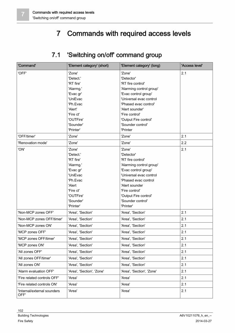
7 Commands with required access levels'Switching on/off' command group
102Building Technologies A6V10211076_h_en_--Fire Safety 2014-03-27
7 Commands with required access levels
7.1 'Switching on/off' command group'Command' 'Element category' (short) 'Element category' (long) 'Access level'
'OFF' 'Zone''Detect.''RT fire''Alarmg.''Evac gr''UniEvac'Ph.Evac'Alert''Fire ct''OUTFire''Sounder''Printer'
'Zone''Detector''RT fire control''Alarming control group''Evac control group''Universal evac control'Phased evac control''Alert sounder''Fire control''Output Fire control''Sounder control''Printer
2.1
'OFF/timer' 'Zone' 'Zone' 2.1
'Renovation mode' 'Zone' 'Zone' 2.2
'ON' 'Zone''Detect.''RT fire''Alarmg.''Evac gr''UniEvac'Ph.Evac'Alert'Fire ct''OUTFire''Sounder''Printer'
'Zone''Detector''RT fire control''Alarming control group''Evac control group''Universal evac control'Phased evac control'Alert sounder'Fire control''Output Fire control''Sounder control''Printer'
2.1
'Non-MCP zones OFF' 'Area', 'Section' 'Area', 'Section' 2.1
'Non-MCP zones OFF/timer' 'Area', 'Section' 'Area', 'Section' 2.1
'Non-MCP zones ON' 'Area', 'Section' 'Area', 'Section' 2.1
'MCP zones OFF' 'Area', 'Section' 'Area', 'Section' 2.1
'MCP zones OFF/timer' 'Area', 'Section' 'Area', 'Section' 2.1
'MCP zones ON' 'Area', 'Section' 'Area', 'Section' 2.1
'All zones OFF' 'Area', 'Section' 'Area', 'Section' 2.1
'All zones OFF/timer' 'Area', 'Section' 'Area', 'Section' 2.1
'All zones ON' 'Area', 'Section' 'Area', 'Section' 2.1
'Alarm evaluation OFF' 'Area', 'Section', 'Zone' 'Area', 'Section', 'Zone' 2.1
'Fire related controls OFF' 'Area' 'Area' 2.1
'Fire related controls ON' 'Area' 'Area' 2.1
'Internal/external soundersOFF'
'Area' 'Area' 2.1
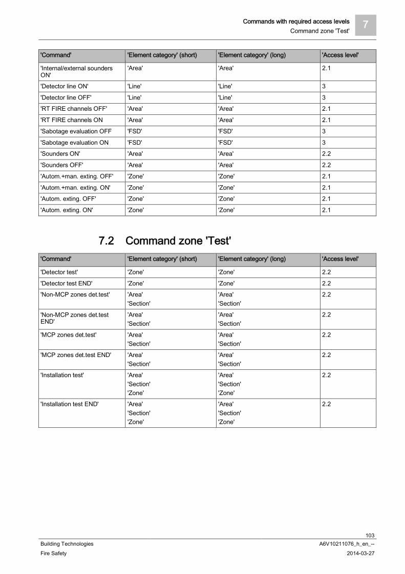
Commands with required access levels 7Command zone 'Test'
103Building Technologies A6V10211076_h_en_--Fire Safety 2014-03-27
'Command' 'Element category' (short) 'Element category' (long) 'Access level'
'Internal/external soundersON'
'Area' 'Area' 2.1
'Detector line ON' 'Line' 'Line' 3
'Detector line OFF' 'Line' 'Line' 3
'RT FIRE channels OFF' 'Area' 'Area' 2.1
'RT FIRE channels ON 'Area' 'Area' 2.1
'Sabotage evaluation OFF 'FSD' 'FSD' 3
'Sabotage evaluation ON 'FSD' 'FSD' 3
'Sounders ON' 'Area' 'Area' 2.2
'Sounders OFF' 'Area' 'Area' 2.2
'Autom.+man. exting. OFF' 'Zone' 'Zone' 2.1
'Autom.+man. exting. ON' 'Zone' 'Zone' 2.1
'Autom. exting. OFF' 'Zone' 'Zone' 2.1
'Autom. exting. ON' 'Zone' 'Zone' 2.1
7.2 Command zone 'Test''Command' 'Element category' (short) 'Element category' (long) 'Access level'
'Detector test' 'Zone' 'Zone' 2.2
'Detector test END' 'Zone' 'Zone' 2.2
'Non-MCP zones det.test' 'Area''Section'
'Area''Section'
2.2
'Non-MCP zones det.testEND'
'Area''Section'
'Area''Section'
2.2
'MCP zones det.test' 'Area''Section'
'Area''Section'
2.2
'MCP zones det.test END' 'Area''Section'
'Area''Section'
2.2
'Installation test' 'Area''Section''Zone'
'Area''Section''Zone'
2.2
'Installation test END' 'Area''Section''Zone'
'Area''Section''Zone'
2.2
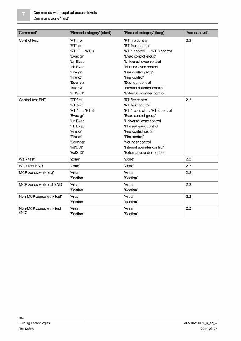
7 Commands with required access levelsCommand zone 'Test'
104Building Technologies A6V10211076_h_en_--Fire Safety 2014-03-27
'Command' 'Element category' (short) 'Element category' (long) 'Access level'
'Control test' 'RT fire''RTfault''RT 1' … 'RT 8''Evac gr''UniEvac'Ph.Evac'Fire gr''Fire ct''Sounder''IntS.Ct''ExtS.Ct'
'RT fire control''RT fault control''RT 1 control' … 'RT 8 control''Evac control group''Universal evac control'Phased evac control'Fire control group''Fire control''Sounder control''Internal sounder control''External sounder control'
2.2
'Control test END' 'RT fire''RTfault''RT 1' … 'RT 8''Evac gr''UniEvac'Ph.Evac'Fire gr''Fire ct''Sounder''IntS.Ct''ExtS.Ct'
'RT fire control''RT fault control''RT 1 control' … 'RT 8 control''Evac control group''Universal evac control'Phased evac control'Fire control group''Fire control''Sounder control''Internal sounder control''External sounder control'
2.2
'Walk test' 'Zone' 'Zone' 2.2
'Walk test END' 'Zone' 'Zone' 2.2
'MCP zones walk test' 'Area''Section'
'Area''Section'
2.2
'MCP zones walk test END' 'Area''Section'
'Area''Section'
2.2
'Non-MCP zones walk test' 'Area''Section'
'Area''Section'
2.2
'Non-MCP zones walk testEND'
'Area''Section'
'Area''Section'
2.2
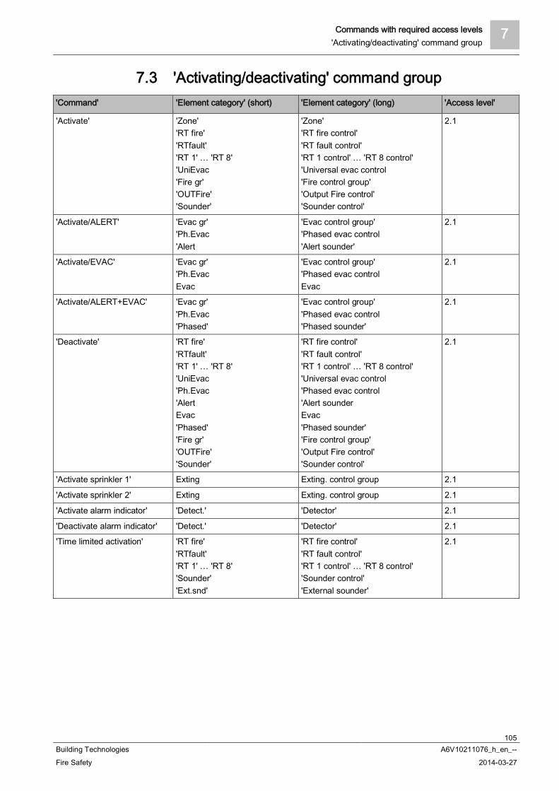
Commands with required access levels 7'Activating/deactivating' command group
105Building Technologies A6V10211076_h_en_--Fire Safety 2014-03-27
7.3 'Activating/deactivating' command group'Command' 'Element category' (short) 'Element category' (long) 'Access level'
'Activate' 'Zone''RT fire''RTfault''RT 1' … 'RT 8''UniEvac'Fire gr''OUTFire''Sounder'
'Zone''RT fire control''RT fault control''RT 1 control' … 'RT 8 control''Universal evac control'Fire control group''Output Fire control''Sounder control'
2.1
'Activate/ALERT' 'Evac gr''Ph.Evac'Alert
'Evac control group''Phased evac control'Alert sounder'
2.1
'Activate/EVAC' 'Evac gr''Ph.EvacEvac
'Evac control group''Phased evac controlEvac
2.1
'Activate/ALERT+EVAC' 'Evac gr''Ph.Evac'Phased'
'Evac control group''Phased evac control'Phased sounder'
2.1
'Deactivate' 'RT fire''RTfault''RT 1' … 'RT 8''UniEvac'Ph.Evac'AlertEvac'Phased''Fire gr''OUTFire''Sounder'
'RT fire control''RT fault control''RT 1 control' … 'RT 8 control''Universal evac control'Phased evac control'Alert sounderEvac'Phased sounder''Fire control group''Output Fire control''Sounder control'
2.1
'Activate sprinkler 1' Exting Exting. control group 2.1
'Activate sprinkler 2' Exting Exting. control group 2.1
'Activate alarm indicator' 'Detect.' 'Detector' 2.1
'Deactivate alarm indicator' 'Detect.' 'Detector' 2.1
'Time limited activation' 'RT fire''RTfault''RT 1' … 'RT 8''Sounder''Ext.snd'
'RT fire control''RT fault control''RT 1 control' … 'RT 8 control''Sounder control''External sounder'
2.1
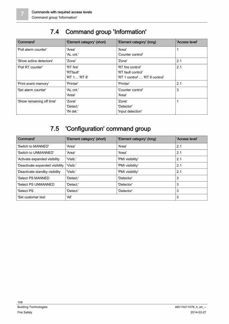
7 Commands with required access levelsCommand group 'Information'
106Building Technologies A6V10211076_h_en_--Fire Safety 2014-03-27
7.4 Command group 'Information''Command' 'Element category' (short) 'Element category' (long) 'Access level'
'Poll alarm counter' 'Area''AL cnt.'
'Area''Counter control'
1
'Show active detectors' 'Zone' 'Zone' 2.1
'Poll RT counter' 'RT fire''RTfault''RT 1… 'RT 8'
'RT fire control''RT fault control''RT 1 control' … 'RT 8 control'
2.1
'Print event memory' 'Printer' 'Printer' 2.1
'Set alarm counter' 'AL cnt.''Area'
'Counter control''Area'
3
'Show remaining off time' 'Zone''Detect.''IN det.'
'Zone''Detector''Input detection'
1
7.5 'Configuration' command group'Command' 'Element category' (short) 'Element category' (long) 'Access level'
'Switch to MANNED' 'Area' 'Area' 2.1
'Switch to UNMANNED' 'Area' 'Area' 2.1
'Activate expanded visibility 'Visib.' 'PMI visibility' 2.1
'Deactivate expanded visibility 'Visib.' 'PMI visibility' 2.1
'Deactivate standby visibility 'Visib.' 'PMI visibility' 2.1
'Select PS MANNED 'Detect.' 'Detector' 3
'Select PS UNMANNED 'Detect.' 'Detector' 3
'Select PS 'Detect.' 'Detector' 3
'Set customer text 'All' 3
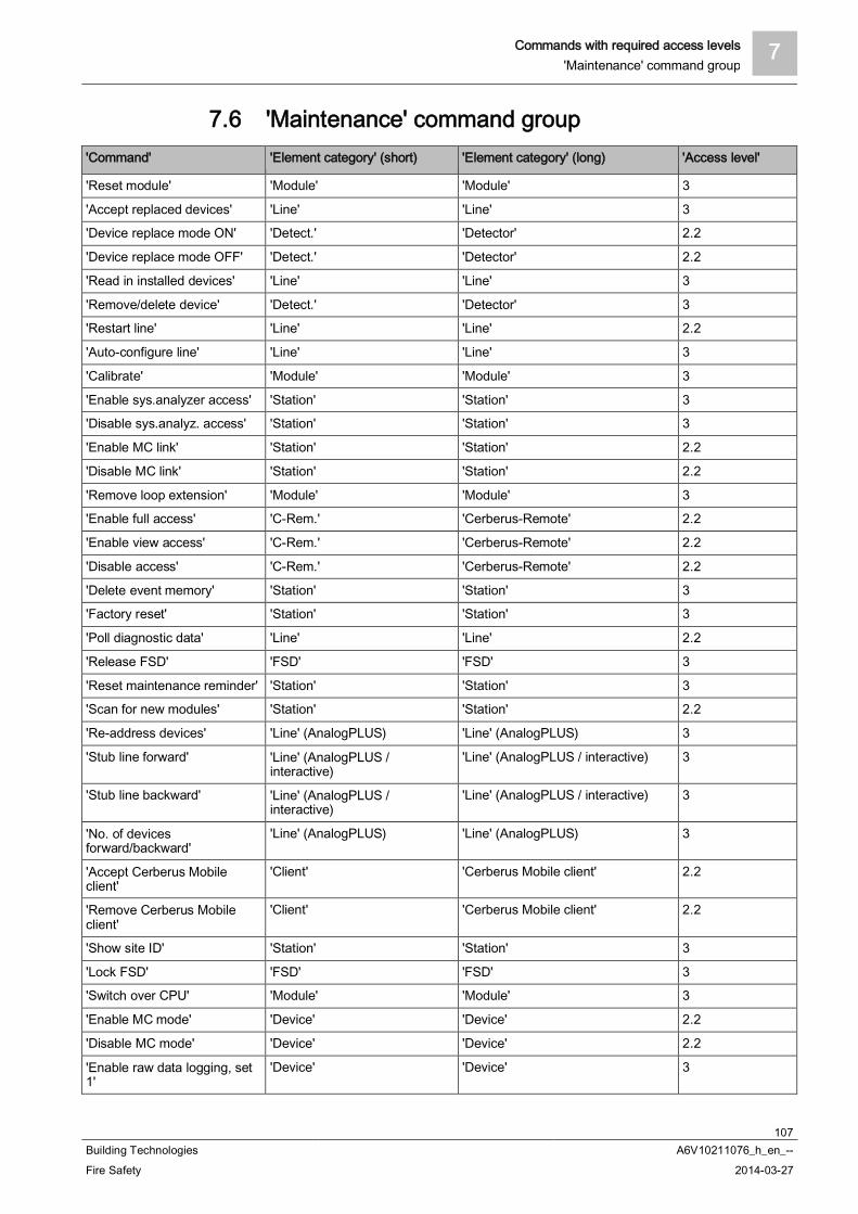
Commands with required access levels 7'Maintenance' command group
107Building Technologies A6V10211076_h_en_--Fire Safety 2014-03-27
7.6 'Maintenance' command group'Command' 'Element category' (short) 'Element category' (long) 'Access level'
'Reset module' 'Module' 'Module' 3
'Accept replaced devices' 'Line' 'Line' 3
'Device replace mode ON' 'Detect.' 'Detector' 2.2
'Device replace mode OFF' 'Detect.' 'Detector' 2.2
'Read in installed devices' 'Line' 'Line' 3
'Remove/delete device' 'Detect.' 'Detector' 3
'Restart line' 'Line' 'Line' 2.2
'Auto-configure line' 'Line' 'Line' 3
'Calibrate' 'Module' 'Module' 3
'Enable sys.analyzer access' 'Station' 'Station' 3
'Disable sys.analyz. access' 'Station' 'Station' 3
'Enable MC link' 'Station' 'Station' 2.2
'Disable MC link' 'Station' 'Station' 2.2
'Remove loop extension' 'Module' 'Module' 3
'Enable full access' 'C-Rem.' 'Cerberus-Remote' 2.2
'Enable view access' 'C-Rem.' 'Cerberus-Remote' 2.2
'Disable access' 'C-Rem.' 'Cerberus-Remote' 2.2
'Delete event memory' 'Station' 'Station' 3
'Factory reset' 'Station' 'Station' 3
'Poll diagnostic data' 'Line' 'Line' 2.2
'Release FSD' 'FSD' 'FSD' 3
'Reset maintenance reminder' 'Station' 'Station' 3
'Scan for new modules' 'Station' 'Station' 2.2
'Re-address devices' 'Line' (AnalogPLUS) 'Line' (AnalogPLUS) 3
'Stub line forward' 'Line' (AnalogPLUS /interactive)
'Line' (AnalogPLUS / interactive) 3
'Stub line backward' 'Line' (AnalogPLUS /interactive)
'Line' (AnalogPLUS / interactive) 3
'No. of devicesforward/backward'
'Line' (AnalogPLUS) 'Line' (AnalogPLUS) 3
'Accept Cerberus Mobileclient'
'Client' 'Cerberus Mobile client' 2.2
'Remove Cerberus Mobileclient'
'Client' 'Cerberus Mobile client' 2.2
'Show site ID' 'Station' 'Station' 3
'Lock FSD' 'FSD' 'FSD' 3
'Switch over CPU' 'Module' 'Module' 3
'Enable MC mode' 'Device' 'Device' 2.2
'Disable MC mode' 'Device' 'Device' 2.2
'Enable raw data logging, set1'
'Device' 'Device' 3
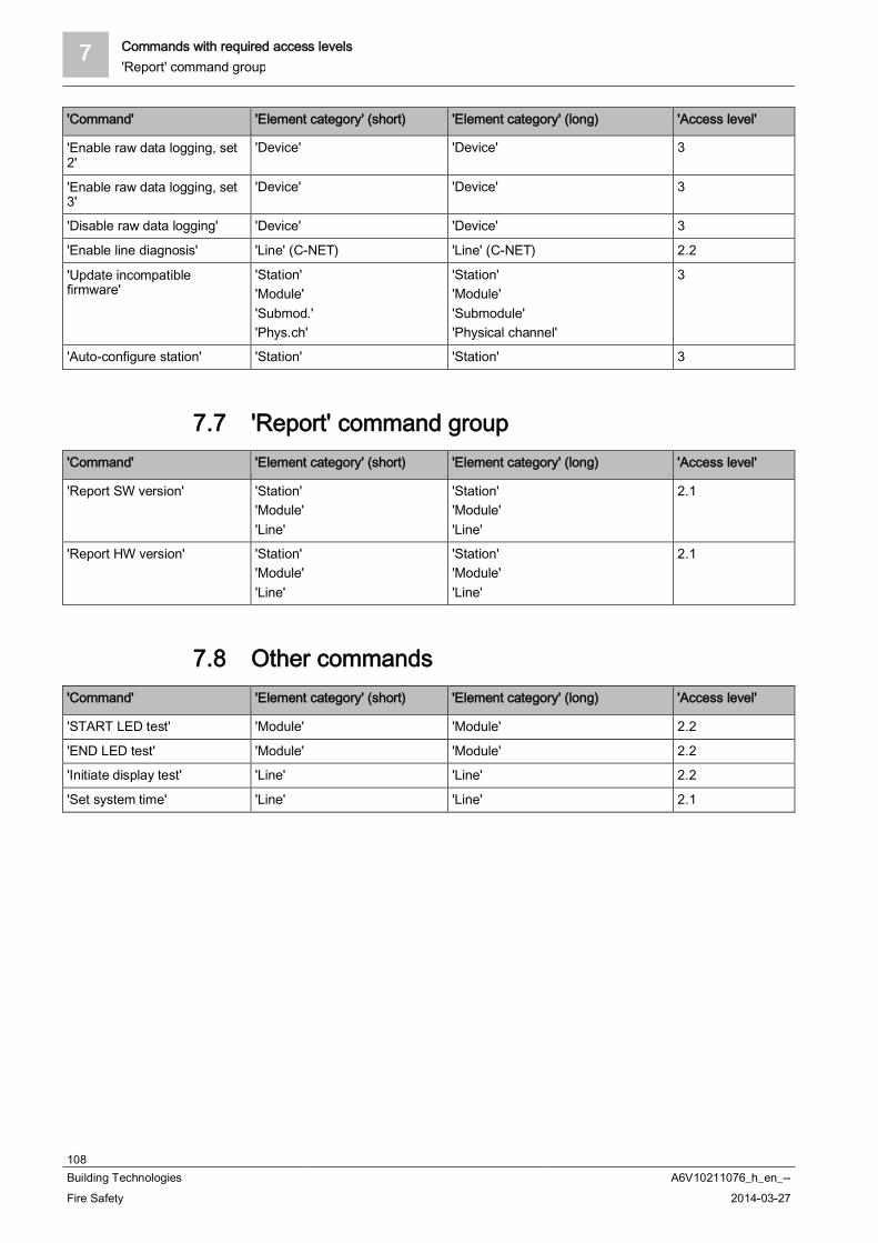
7 Commands with required access levels'Report' command group
108Building Technologies A6V10211076_h_en_--Fire Safety 2014-03-27
'Command' 'Element category' (short) 'Element category' (long) 'Access level'
'Enable raw data logging, set2'
'Device' 'Device' 3
'Enable raw data logging, set3'
'Device' 'Device' 3
'Disable raw data logging' 'Device' 'Device' 3
'Enable line diagnosis' 'Line' (C-NET) 'Line' (C-NET) 2.2
'Update incompatiblefirmware'
'Station''Module''Submod.''Phys.ch'
'Station''Module''Submodule''Physical channel'
3
'Auto-configure station' 'Station' 'Station' 3
7.7 'Report' command group'Command' 'Element category' (short) 'Element category' (long) 'Access level'
'Report SW version' 'Station''Module''Line'
'Station''Module''Line'
2.1
'Report HW version' 'Station''Module''Line'
'Station''Module''Line'
2.1
7.8 Other commands'Command' 'Element category' (short) 'Element category' (long) 'Access level'
'START LED test' 'Module' 'Module' 2.2
'END LED test' 'Module' 'Module' 2.2
'Initiate display test' 'Line' 'Line' 2.2
'Set system time' 'Line' 'Line' 2.1

List of elements 8
109Building Technologies A6V10211076_h_en_--Fire Safety 2014-03-27
8 List of elementsElement short text / long text Definition
'Area' /'Area'
Highest level in the 'Detection tree', alarm organization level
'Section' /'Section'
2. nd level in the 'Detection tree', building section (e.g. room, floor,staircase), enabling unambiguous identification and location of a fire alarm
'Zone' /'Zone'
3. level of the 'Detection tree'; decision on alarm is taken on this level
'Detect.' /'Detector'
Lowest level in 'Detection tree'
'Control' /'Control'
General control
'Evac ct' /'Evac control'
3. level in 'Control tree'
'Evac gr' /'Evac control group'
2. level in 'Control tree'
'Fire ct' /'Fire control'
3. level in 'Control tree'
'Fire gr' /'Fire control group'
2. level in 'Control tree'
'RT fire' /'RT fire control'
3. level in 'Control tree'
'RTfault' /'RT fault control'
3. level in 'Control tree'
'RT 1' … 'RT 8' /'RT 1 control' … 'RT 8 control'
3. level in 'Control tree'
'Alarmg.' /'Alarming control group'
2. level in 'Control tree'
'Sounder' /'Sounder control'
3. level in 'Control tree'
'Sounder' /'Sounder'
2. level in 'Control tree'
'Phased' /'Phased sounder 5686'
Lowest level in 'Control tree'
'Evac' /'Evac sounder'
Lowest level in 'Control tree'
'Sounder' /'Sounders' alarming control
Lowest level in 'Control tree'
'Sounder' /'Sounders' fire control
Lowest level in 'Control tree'
'Station' /'Station'
Highest level in 'Hardware tree'
'Station' /'Station'
'Station' network

8 List of elements
110Building Technologies A6V10211076_h_en_--Fire Safety 2014-03-27
Element short text / long text Definition
'Printer' /'Printer'
'Station' printer
'Station' /'Station'
Highest level in 'Hardware tree', control panel
'Module' /'Module'
2. level in 'Hardware tree'
'Line' /'Line'
3. level in 'Hardware tree', primary detection line
'Device' /'Device'
Lowest level in 'Hardware tree', functions of the physical device
'Supply /'Power supply'
Mains / Battery
'FRT' Object display with operation function
'FRD' Object display without operation function
'Phys.ch' /'Physical channel'
Lowest level in 'Hardware tree'
'PMI' /'PMI'
'Station' operating unit
'LED ind' /'LED indicator/mimic display driver'
LED indication unit on the P2 periphery bus
'Keydep.' /'Key depot'
Fire department key depot
'BN dev.' /'BACnet device object'
'BN dev.' device connection
'FAT /'FAT
Fire brigade indication panel
'FAT/FBF' /'FAT with FBF'
Fire brigade indication panel with integrated fire brigade operating panel
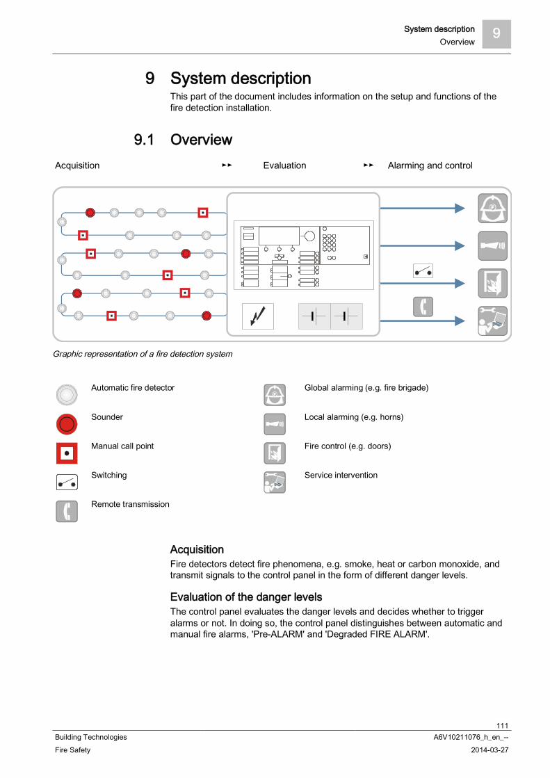
System description 9Overview
111Building Technologies A6V10211076_h_en_--Fire Safety 2014-03-27
9 System descriptionThis part of the document includes information on the setup and functions of thefire detection installation.
9.1 OverviewAcquisition Evaluation Alarming and control
Graphic representation of a fire detection system
Automatic fire detector Global alarming (e.g. fire brigade)
Sounder Local alarming (e.g. horns)
Manual call point Fire control (e.g. doors)
Switching Service intervention
Remote transmission
AcquisitionFire detectors detect fire phenomena, e.g. smoke, heat or carbon monoxide, andtransmit signals to the control panel in the form of different danger levels.
Evaluation of the danger levelsThe control panel evaluates the danger levels and decides whether to triggeralarms or not. In doing so, the control panel distinguishes between automatic andmanual fire alarms, 'Pre-ALARM' and 'Degraded FIRE ALARM'.
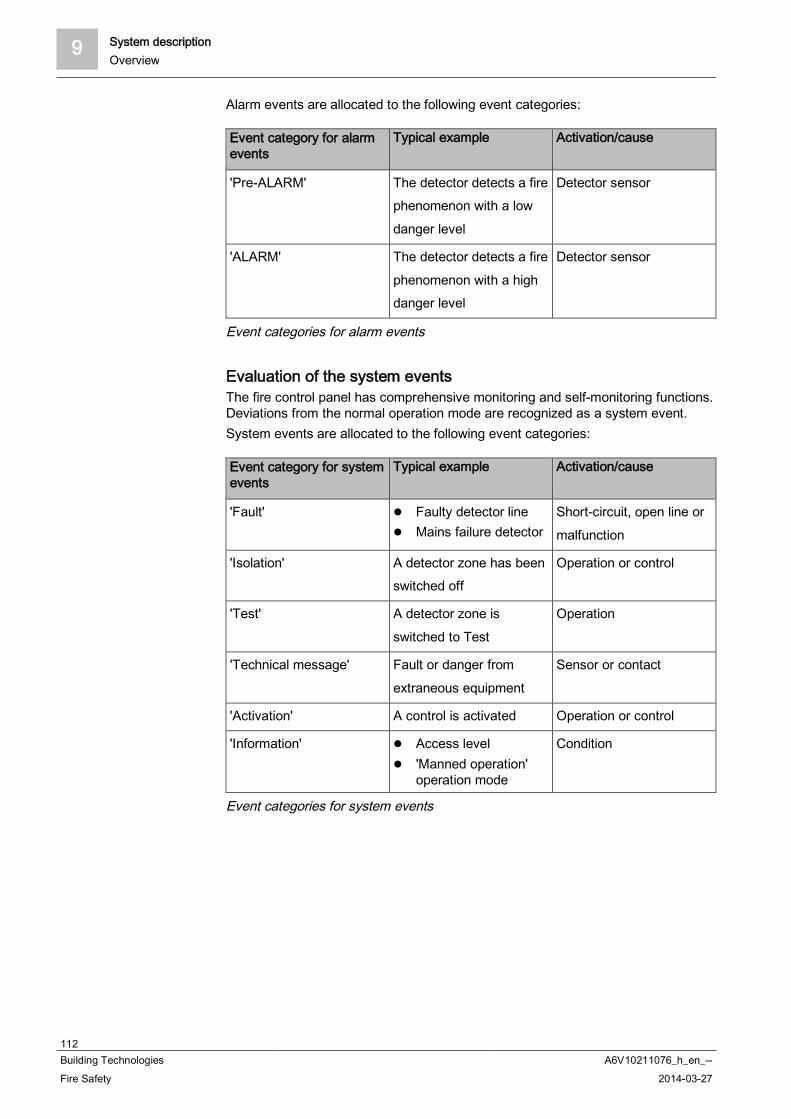
9 System descriptionOverview
112Building Technologies A6V10211076_h_en_--Fire Safety 2014-03-27
Alarm events are allocated to the following event categories:
Event category for alarmevents
Typical example Activation/cause
'Pre-ALARM' The detector detects a firephenomenon with a lowdanger level
Detector sensor
'ALARM' The detector detects a firephenomenon with a highdanger level
Detector sensor
Event categories for alarm events
Evaluation of the system eventsThe fire control panel has comprehensive monitoring and self-monitoring functions.Deviations from the normal operation mode are recognized as a system event.System events are allocated to the following event categories:
Event category for systemevents
Typical example Activation/cause
'Fault' Faulty detector line Mains failure detector
Short-circuit, open line ormalfunction
'Isolation' A detector zone has beenswitched off
Operation or control
'Test' A detector zone isswitched to Test
Operation
'Technical message' Fault or danger fromextraneous equipment
Sensor or contact
'Activation' A control is activated Operation or control
'Information' Access level 'Manned operation'
operation mode
Condition
Event categories for system events
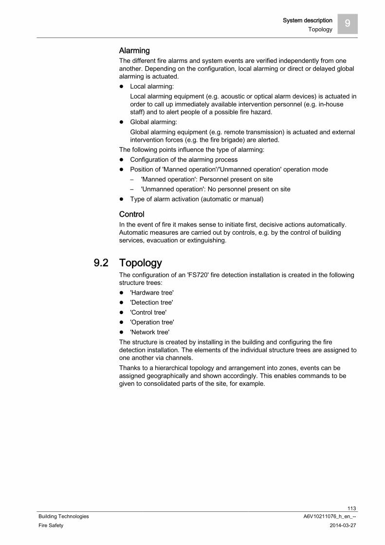
System description 9Topology
113Building Technologies A6V10211076_h_en_--Fire Safety 2014-03-27
AlarmingThe different fire alarms and system events are verified independently from oneanother. Depending on the configuration, local alarming or direct or delayed globalalarming is actuated.
Local alarming:Local alarming equipment (e.g. acoustic or optical alarm devices) is actuated inorder to call up immediately available intervention personnel (e.g. in-housestaff) and to alert people of a possible fire hazard.
Global alarming:Global alarming equipment (e.g. remote transmission) is actuated and externalintervention forces (e.g. the fire brigade) are alerted.
The following points influence the type of alarming: Configuration of the alarming process Position of 'Manned operation'/'Unmanned operation' operation mode
– 'Manned operation': Personnel present on site– 'Unmanned operation': No personnel present on site
Type of alarm activation (automatic or manual)
ControlIn the event of fire it makes sense to initiate first, decisive actions automatically.Automatic measures are carried out by controls, e.g. by the control of buildingservices, evacuation or extinguishing.
9.2 TopologyThe configuration of an 'FS720' fire detection installation is created in the followingstructure trees:
'Hardware tree' 'Detection tree' 'Control tree' 'Operation tree' 'Network tree'
The structure is created by installing in the building and configuring the firedetection installation. The elements of the individual structure trees are assigned toone another via channels.Thanks to a hierarchical topology and arrangement into zones, events can beassigned geographically and shown accordingly. This enables commands to begiven to consolidated parts of the site, for example.

9 System descriptionTopology
114Building Technologies A6V10211076_h_en_--Fire Safety 2014-03-27
9.2.1 Hardware treeThe 'Hardware tree' represents the installed hardware. The individual elements ofthe 'Hardware tree' are structured as follows:
'Station' 'Module' 'Line' 'Device' 'Physical channel'
'Hardware tree' (example)
1 'Station'2 'Module'
3 'Device'
Dotted line 'Line'
9.2.2 Detection treeThe 'Detection tree' is an image of the geographic and functional situations in a'Site'. It is adapted to the building structure and room use. The 'Detection tree' isindependent from the line arrangement of the detector network.
'Detection tree' elements and typical representation 'Area'
– Building 'Section'
– Floor or staircase 'Zone'
– Room 'Channel'
– Logical detector function

System description 9Topology
115Building Technologies A6V10211076_h_en_--Fire Safety 2014-03-27
'Detection tree' (example)
1 'Area'
2 'Section'3 'Zone'
4 'Channel'/ 'Detector'
9.2.2.1 Elements of the detection tree
'Area' 'Area' typically corresponds to a building. 'Area' combines 'Sections' which are subject to the same 'Manned
operation'/'Unmanned operation' operation mode. 'Area' actuates the alarming equipment (acoustic and optical alarming devices
as well as remote transmission). 'Area' is assigned the following functions:
– 'Manned operation'/'Unmanned operation' operation mode– Switching assigned 'Sections' on/off
Several 'Areas' are possible per control panel: FC722, FC723, FC724: up to four 'Areas' FC726 up to eight 'Areas'
There is an 'Area' that groups together the functions of alarm verification (AVC),e.g. collective alarms and degraded mode operation.
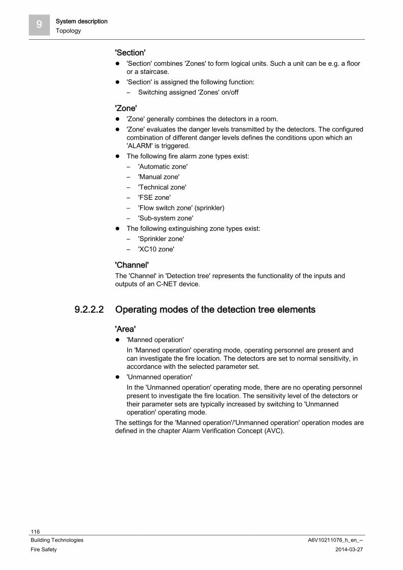
9 System descriptionTopology
116Building Technologies A6V10211076_h_en_--Fire Safety 2014-03-27
'Section' 'Section' combines 'Zones' to form logical units. Such a unit can be e.g. a floor
or a staircase. 'Section' is assigned the following function:
– Switching assigned 'Zones' on/off
'Zone' 'Zone' generally combines the detectors in a room. 'Zone' evaluates the danger levels transmitted by the detectors. The configured
combination of different danger levels defines the conditions upon which an'ALARM' is triggered.
The following fire alarm zone types exist:– 'Automatic zone'– 'Manual zone'– 'Technical zone'– 'FSE zone'– 'Flow switch zone' (sprinkler)– 'Sub-system zone'
The following extinguishing zone types exist:– 'Sprinkler zone'– 'XC10 zone'
'Channel'The 'Channel' in 'Detection tree' represents the functionality of the inputs andoutputs of an C-NET device.
9.2.2.2 Operating modes of the detection tree elements
'Area' 'Manned operation'
In 'Manned operation' operating mode, operating personnel are present andcan investigate the fire location. The detectors are set to normal sensitivity, inaccordance with the selected parameter set.
'Unmanned operation'In the 'Unmanned operation' operating mode, there are no operating personnelpresent to investigate the fire location. The sensitivity level of the detectors ortheir parameter sets are typically increased by switching to 'Unmannedoperation' operating mode.
The settings for the 'Manned operation'/'Unmanned operation' operation modes aredefined in the chapter Alarm Verification Concept (AVC).

System description 9Topology
117Building Technologies A6V10211076_h_en_--Fire Safety 2014-03-27
'Zone' Switched on (normal operation)
Danger levels are evaluated and 'ALARMS' produced in normal operation. Thedetectors have a normal sensitivity level, in accordance with the selectedparameter set.
Switched offIf a 'Zone' is switched off, the channels assigned to the 'Zone' are isolated. Nosignals are evaluated, neither danger levels nor 'Faults'.There are two isolation functions:– Isolation without time limits– Isolation with time limits
' --Renovation mode'This operating mode is not assigned a function.
'Detector test'In the 'Detector test' operating mode, detectors can be actuated for testpurposes. When a detector is triggered, a test activation message is generated.Alarm devices or controls are not activated.The following devices are activated:– Internal alarm indicators– External alarm indicators in accordance with the configuration– Base sounders if they are in the base of the activated detectorDuring testing the detectors must react quickly so that the holding times areshort. During the 'Detector test', the detectors are switched to increasedsensitivity with the 'Test' parameter set for this purpose.After terminating the 'Detector test' operating mode, the detectors and'Zones'are reset to the condition they were in before the 'Detector test'.
'Installation test'An 'Installation test' can be performed during normal operation. The alarmdevices and controls are activated.In the test the detectors must react quickly so that the holding times are short.During the 'Installation test', the detectors are switched to increased sensitivitywith the 'Test' parameter set for this purpose.After terminating the 'Installation test' operating mode, the detectors and'Zones'are reset to the condition they were in before the 'Installation test'operating mode.
'Channel' Switched on (normal operation)
In the normal operation, the danger levels of the detector as well as any 'Faults'are transmitted to the 'Zone' for evaluation.
Switched offIf a 'Channel' is switched off, no signals are forwarded to the 'Zone', neitherdanger levels nor 'Faults'.

9 System descriptionTopology
118Building Technologies A6V10211076_h_en_--Fire Safety 2014-03-27
9.2.2.3 Functions of the detection tree elements
'Area': Switching the operating mode The 'Unmanned operation' operating mode is manually switched to 'Manned
operation'. Switching is not possible when 'ALARMS' have occurred and needto be dealt with.
The 'Manned operation' operating mode is automatically or manually(configurable) switched to 'Unmanned operation'. Four time settings can beconfigured for this, regardless of the day of the week:– The first time setting is for automatic changeover.– The second, third and fourth time setting is for safety reasons, in case
somebody switches to 'Manned operation' after the expiry of the first,second or third automatic changeover.
Blocking switchover– If an 'ALARM' has occurred in the 'Area' and is waiting for treatment, the
switchover function from 'Manned operation' to 'Unmanned operation' isblocked.
– It is still possible to switch from 'Unmanned operation' to 'Mannedoperation'.
Switching functions on and off– All functions available for the 'Zones' are also available as collective
functions at area level.Examples:– Switching all automatic 'Zones' on and off.– Switching all manual 'Zones' on and off.
'Poll alarm counter'– The alarm counter counts the number of alarm states of the 'Area'.– The alarm state is the state from the first 'ALARM' to the successful reset.
'Section': 'Zones': switching on and off All 'Zones' of the same kind (automatic/manual) can be switched off and on
within the section. 'Zones' with automatic fire detectors and 'Zones' with manualcall points are treated differently.
'Zone': reset behaviour of the manual call points The reset behavior of an activated manual call point can be selected:
– 'ALARM'can always be reset; 'Glass broken' is indicated.or
– 'ALARM' cannot be reset. Blocking of the isolation
– If the isolation blocking function has been configured, the 'Zone' cannot beswitched off.
'Detector test' timeout– After the expiry of a configurable delay the system automatically cancels
the 'Detector test' state. This function can be deactivated. Switching devices back on
– When devices are switched back on, they are in an undefined state for ashort period. The 'Station' changes to the 'Not ready' state for this period.
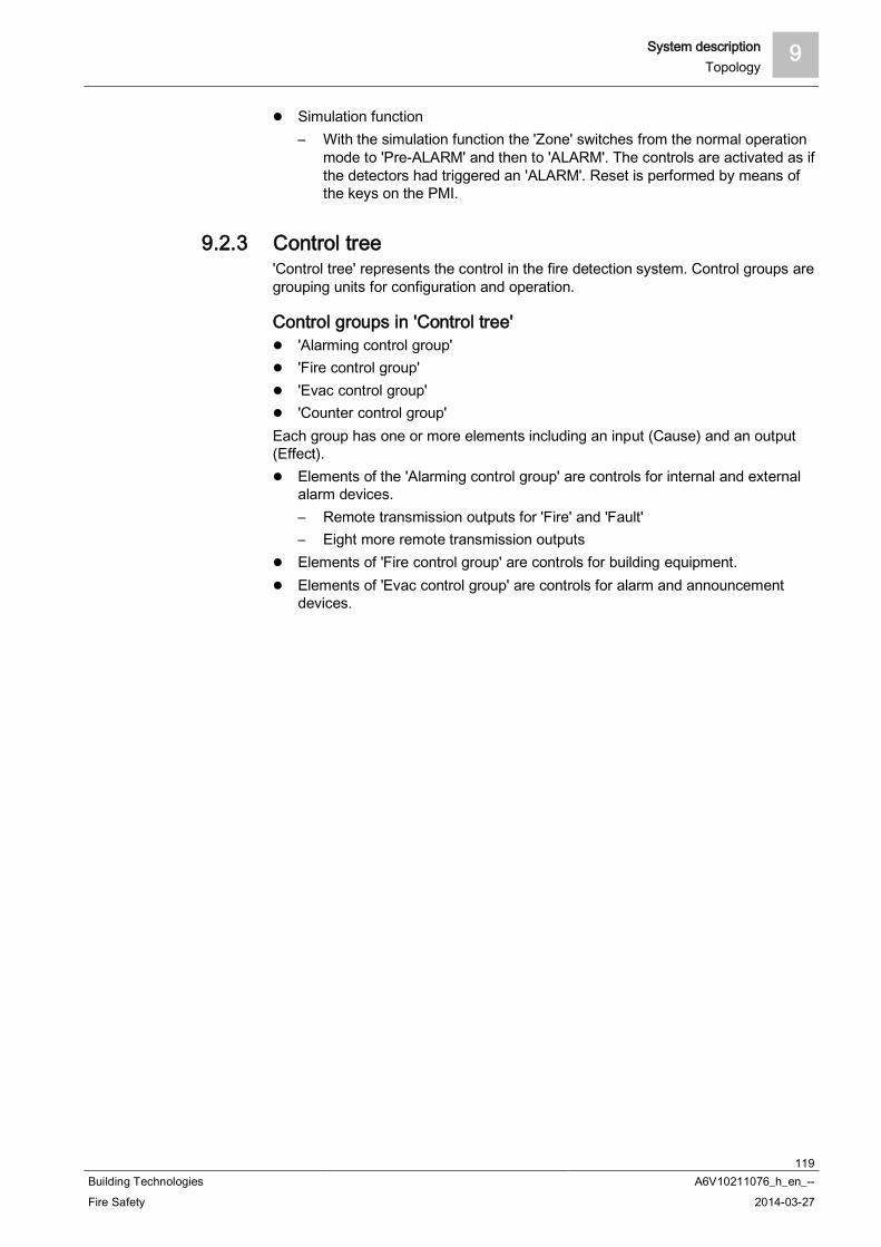
System description 9Topology
119Building Technologies A6V10211076_h_en_--Fire Safety 2014-03-27
Simulation function– With the simulation function the 'Zone' switches from the normal operation
mode to 'Pre-ALARM' and then to 'ALARM'. The controls are activated as ifthe detectors had triggered an 'ALARM'. Reset is performed by means ofthe keys on the PMI.
9.2.3 Control tree'Control tree' represents the control in the fire detection system. Control groups aregrouping units for configuration and operation.
Control groups in 'Control tree' 'Alarming control group' 'Fire control group' 'Evac control group' 'Counter control group'
Each group has one or more elements including an input (Cause) and an output(Effect).
Elements of the 'Alarming control group' are controls for internal and externalalarm devices.– Remote transmission outputs for 'Fire' and 'Fault'– Eight more remote transmission outputs
Elements of 'Fire control group' are controls for building equipment. Elements of 'Evac control group' are controls for alarm and announcement
devices.

9 System descriptionTopology
120Building Technologies A6V10211076_h_en_--Fire Safety 2014-03-27
Effects in 'Control tree' (example)
C 'Control tree'1 5 control groups (a - e)
2 Controls
3 Devices and remote transmission, 2 circuitsLines Logical link
Arrows Signal transfer
a 'Evac control group'b 'Fire control group' e.g. for door controls
c 'Fire control group' for alarm indicators (external AI)
d 'Fire control group' for commandsX E.g. isolation, commands to other installation parts
e 'Alarming control group' for alarm devices and remote transmission
Y Local or global alarming

System description 9Topology
121Building Technologies A6V10211076_h_en_--Fire Safety 2014-03-27
9.2.4 Operating treeThe following elements and settings are represented in the Operation tree:
Global system configuration Display and operator units such as:
– Person Machine Interface (PMI)– Floor repeater terminal and floor repeater display– Mimic display– Event printer
Global system configurationThe global system configuration has the following elements:
Global behaviour– Events (event configuration)– Commands ('Access level' assignment)
The behavior set here is always valid unless a different behavior is set locally. Master clock: The master clock is automatically assigned to the first station
(address 1). Country settings: Settings are undertaken here for localization and changing
between summer and winter time.
Person Machine Interface (PMI)The PMI is a permanent part of the station. The following settings can beconfigured in the Operation tree:
Basic settings with definition of default access level for the key switch and timeperiod during which the display returns to the normal display from an operatingdisplay.
Visibility:A detailed description of the visibility can be found in the correspondingchapter.– Standard visibility– Standby visibility– Expanded visibility
LEDs for signaling events and statuses (causes):– Event with defined, local visibility.– Event with optional, global visibility on particular element from the
Hardware tree, Detection tree or Control tree. Standard keys:
Frequently used functions can be assigned to the configurable standard keys.– Views, e.g. message indicator, customer text view, fire brigade view– Commands, e.g. activate/deactivate, test, configuration ('Set PS MANNED',
'Switch to UNMANNED', etc.). Favorite keys:
The favorite keys are in the display menu. There is a maximum of eight favoritekeys of which three are preconfigured. Frequently used functions can beassigned to the favorite keys.

9 System descriptionTopology
122Building Technologies A6V10211076_h_en_--Fire Safety 2014-03-27
Floor repeater terminal FT2010The following settings can be configured in the Operation tree:
Visibility Cause for activating the LEDs Views and commands for the function keys
Floor repeater display FT2011The following settings can be configured in the Operation tree:
Visibility Cause for activating an LED
Mimic displayThere are two possible ways of configuring the LED indicator (internal) FTO2002and the LED module FTO2008-A1:
Visibility of the 24 LED groups (red/yellow) or (red/green, yellow) on a Sectionor Zone.
Visibility of each of the 48 LEDs on any event.
Mimic display driver FT2001The mimic display driver activates up to 48 LEDs which are fitted on a ground planpanel. Communication is via the C-NET.The mimic display driver also has two control outputs for local buzzer and'SystemOn' LED along with two inputs for 'Silence buzzer' and 'START LED test'.
Event printerThe event printer logs all system events in the configured view.
Fire department periphery [DE]The fire department periphery comprises the following devices:
Fire department operating panel (FBF) Fire department key depot (FSD) Fire department display terminal (FAT) FAT with FBF
FSD is assigned to the fire department periphery module FCI2001.FBF can either be connected via the fire brigade periphery module FCI2001 or anRS485 interface.FAT and FAT with FBF are connected to the station via a serial interface RS 485.To configure the devices, the logical element must be created in the 'Operation'task card and assigned to the corresponding hardware element.

System description 9Topology
123Building Technologies A6V10211076_h_en_--Fire Safety 2014-03-27
9.2.5 Network treeThe network tree represents the networking of an FS720 system.
Networking typesThe stations in the fire detection system can be networked in the following ways:
SAFEDLINK (system bus) SAFEDLINK, extended: coupling of several SAFEDLINK sub-nets via C-
WEB/LAN (optical Ethernet) Electric Ethernet (does not comply with EN 54) SAFEDLINK and Ethernet mixed (does not comply with EN 54)
Connection types/functionsThe stations in the network can have the following connection types/functions:
Stand-alone station SAFEDLINK station: station in the SAFEDLINK network Router station: station in the SAFEDLINK sub-net connected to the C-
WEB/LAN Ethernet station: station in the Ethernet sub-network to which no more stations
are connected via SAFEDLINK GAP station: Station in the network for connecting to a management station
(BACnet client)– The GAP station has the function of a DHCP server (configurable)– The DHCP server automatically issues IP addresses to the clients from a
defined IP address space. This enables a PC to receive local access, forexample
A route to an external IP router can be defined for the GAP station
Extended networkingExtended networking is the merging of several SAFEDLINK sub-nets via C-WEB/LAN, which is managed as optical Ethernet in loop topology.The sub-networks communicate via the router stations.
Private/external network Private network: FS720fire detection installations have their own cabling. The
IP addresses come from a reserved range for private networks External network: Fire detection installations can be incorporated in an existing
IT infrastructure as sub-nets Integration in an external network does not comply with EN 54
Connection with management stationsThe connection between management stations or other sub-systems and theFS720 sub-system is established via BACnet/Ethernet.A management station is connected to the FS720 sub-system via the GAP'sEthernet interface. Every single station that is to use the BACnet protocol must beenabled with a license key. The license key must support the BACnet function formanagement stations.
You will find more information about license keys in document A6V10210362.See chapter 'Applicable documents'.

9 System descriptionTopology
124Building Technologies A6V10211076_h_en_--Fire Safety 2014-03-27
9.2.6 Assigning with the hardware treeComponents can be allocated to a geographical location in the system. Thisassignment is a link.
Geographical allocationEach device in the 'Hardware tree' has a unique address. In 'Detection tree', it ispossible to allocate room x on floor y to the device, for example.
Sample assigning of the detection tree to the hardware tree
D 'Detection tree'
L LinkHW 'Hardware tree'
The physical and the logical channel of a device are assigned between the'Detection tree' and 'Hardware tree'.The physical channel is the lowest level in the 'Hardware tree' and maps thephysical function of a device.The logical channel is the lowest level in the 'Detection tree' and maps the logicalfunction of a device.

System description 9Topology
125Building Technologies A6V10211076_h_en_--Fire Safety 2014-03-27
9.2.7 Functional allocationIn the 'Control tree', a function is assigned to a device from the 'Hardware tree', forexample a monitoring function (cause) is assigned to an input or a control function(effect) is assigned to an output.In the 'Control tree', the function of a logical element from the 'Detection tree' isevaluated (cause) or controlled (effect). For example, the alarm condition of the'Control tree' is evaluated or the 'Detection tree' is switched on or off.The figure below shows the interrelations of the aforementioned structures by wayof example.
Example of functional assignment
D 'Detection tree'
C 'Control tree'L Link
HW 'Hardware tree'
a - e Control groupsf Controls
X E.g. isolation, commands to other installation parts
L Local alarmingAlarming equipment (e.g. acoustic or optical alarm devices) is actuated in order to call up immediately availableintervention personnel (e.g. in-house staff) and to alert people of a possible fire hazard.
G Global alarmingAlarming equipment (e.g. remote transmission) is actuated and external intervention forces (e.g. the fire brigade)are alerted.Visualization of the link from causes and effects via controls
Lines Signal transfer or logical link

9 System descriptionAcquisition
126Building Technologies A6V10211076_h_en_--Fire Safety 2014-03-27
9.3 AcquisitionThe detectors detect the fire phenomena, e.g. smoke, heat or carbon monoxide,and transmit the danger level to the 'Zone'.
Information flow of the danger levels
D 'Detection tree'
a Detector / channel
b 'Zone'0…3 Danger levels
Overview of danger levels, divided according to line type anddetector type
Danger level Addressed detector line Collective detector line Technical input
Automatic Manual
0 No danger No danger No danger No danger (entry contact opened)
1 Possible danger Button notpressed
Detector line resetting –
2 Probable danger – Alarm verification of thefirst alarm is running
Danger Input contact closed Input configured as not relevant for
degraded mode
3 Highly probabledanger
Button pressed,danger
Highly probable danger Danger Input contact closed Input configured as not relevant for
degraded mode
Danger levels

System description 9Evaluation
127Building Technologies A6V10211076_h_en_--Fire Safety 2014-03-27
9.4 EvaluationThe evaluation of the danger level and the decision to trigger an 'ALARM' or nottakes place on 'Zone'.The danger levels of several alarming detectors are combined in the 'Zone'. Thefollowing zone types exist:
'Manual zone' 'Automatic zone' 'Technical zone' 'FSE zone' 'Sprinkler zone' 'XC10 zone'
Information flow of alarm and pre-alarm
D 'Detection tree'1 'Area'
2 'Section'
3 'Zone'm 'Manual zone'
ax Automatic detector group with multi-detector dependency
a1 Automatic detector zone with single-detector dependencyI/O 'Technical zone'
Dashed arrows 'ALARM'/'Pre-ALARM'

9 System descriptionEvaluation
128Building Technologies A6V10211076_h_en_--Fire Safety 2014-03-27
'Manual zone'A 'Manual zone' combines the 'Manual call points'. Danger signals are evaluated bymeans of an OR relation. Each detector of a 'Manual zone' can generate 'ALARM',but not 'Pre-ALARM'.
'Automatic zone'A 'Automatic zone' combines 'Automatic detectors'. The 'Automatic zone' cangenerate 'Pre-ALARM' and 'ALARM'. A distinction is made between the followingdetector dependencies:
Multi-detector dependencyWith multi-detector dependency, the danger levels of several detectors arelinked (AND relation) and evaluated. A 'Pre-ALARM' or 'ALARM' is generatedwhen the defined danger levels have been reached.Several evaluation variants are possible in multi-detector dependency.
Single-detector dependencyWith single-detector dependency the danger levels of one or more detectorsare linked (OR relation). A 'Pre-ALARM' or 'ALARM' is generated as soon as atleast one detector has reached the defined danger level.
Sample criteria for 'Pre-ALARM' or 'ALARM'
Alarm level Single-detector dependency Multi-detector dependency
'Pre-ALARM' 1 x danger level 2 1 x danger level 2 or 3
'ALARM' 1 x danger level 3 2 x danger level 2 or 3
Alarm levels
'Technical zone'In a 'Technical zone', inputs for technical messages are combined, e.g. fault ordanger by extraneous equipment.
'FSE zone'A release element is assigned to this zone. With the release element, a fire alarmis generated manually, which in turn releases the lock to the 'Key depots' with thekeys for the building. To operate the release element, a key is required which isexclusively in the possession of the fire department.
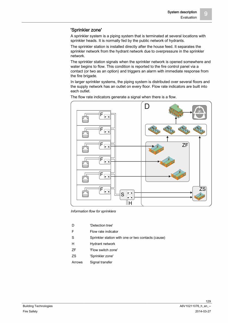
System description 9Evaluation
129Building Technologies A6V10211076_h_en_--Fire Safety 2014-03-27
'Sprinkler zone'A sprinkler system is a piping system that is terminated at several locations withsprinkler heads. It is normally fed by the public network of hydrants.The sprinkler station is installed directly after the house feed. It separates thesprinkler network from the hydrant network due to overpressure in the sprinklernetwork.The sprinkler station signals when the sprinkler network is opened somewhere andwater begins to flow. This condition is reported to the fire control panel via acontact (or two as an option) and triggers an alarm with immediate response fromthe fire brigade.In larger sprinkler systems, the piping system is distributed over several floors andthe supply network has an outlet on every floor. Flow rate indicators are built intoeach outlet.The flow rate indicators generate a signal when there is a flow.
Information flow for sprinklers
D 'Detection tree'
F Flow rate indicatorS Sprinkler station with one or two contacts (cause)
H Hydrant network
ZF 'Flow switch zone'ZS 'Sprinkler zone'
Arrows Signal transfer

9 System descriptionEvaluation
130Building Technologies A6V10211076_h_en_--Fire Safety 2014-03-27
'XC10 zone'Extinguishing is actuated and monitored by the autonomous extinguishing controlunit XC10.An interface to the extinguishing control unit makes it possible to sendextinguishing control unit functions to the fire control panel, and to transmitcommands from the fire control panel to the extinguishing control unit.
Information flow from the extinguishing control unit XC10
D 'Detection tree'
XC10 Extinguishing control unitI Extinguishing control unit inputs: 'Extinguishing activated', 'Fault', 'Pre-alarm',
'Autom. + manual extinguishing OFF'O Extinguishing control unit outputs: 'Reset', 'Autom. Blocking extinguishing
activation, 'Autom. + manual extinguishing activation blocked'Z 'XC10 zone'
You will find detailed information in the Technical manual for the extinguishingcontrol unit XC10, document 008399.
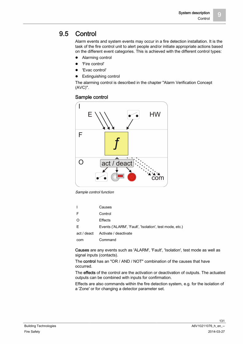
System description 9Control
131Building Technologies A6V10211076_h_en_--Fire Safety 2014-03-27
9.5 ControlAlarm events and system events may occur in a fire detection installation. It is thetask of the fire control unit to alert people and/or initiate appropriate actions basedon the different event categories. This is achieved with the different control types:
Alarming control 'Fire control' 'Evac control' Extinguishing control
The alarming control is described in the chapter "Alarm Verification Concept(AVC)".
Sample control
Sample control function
I Causes
F ControlO Effects
E Events ('ALARM', 'Fault', 'Isolation', test mode, etc.)
act / deact Activate / deactivatecom Command
Causes are any events such as 'ALARM', 'Fault', 'Isolation', test mode as well assignal inputs (contacts).The control has an "OR / AND / NOT" combination of the causes that haveoccurred.The effects of the control are the activation or deactivation of outputs. The actuatedoutputs can be combined with inputs for confirmation.Effects are also commands within the fire detection system, e.g. for the isolation ofa 'Zone' or for changing a detector parameter set.
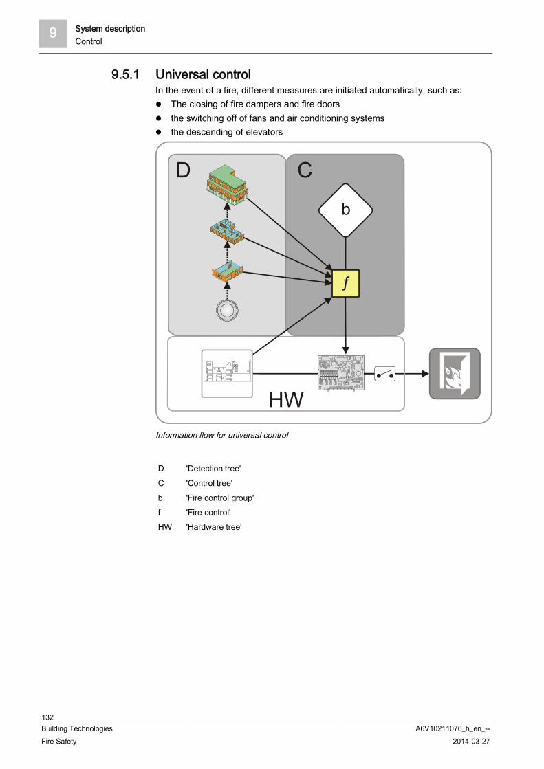
9 System descriptionControl
132Building Technologies A6V10211076_h_en_--Fire Safety 2014-03-27
9.5.1 Universal controlIn the event of a fire, different measures are initiated automatically, such as:
The closing of fire dampers and fire doors the switching off of fans and air conditioning systems the descending of elevators
Information flow for universal control
D 'Detection tree'
C 'Control tree'
b 'Fire control group'f 'Fire control'
HW 'Hardware tree'
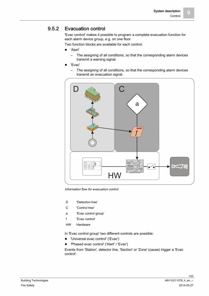
System description 9Control
133Building Technologies A6V10211076_h_en_--Fire Safety 2014-03-27
9.5.2 Evacuation control'Evac control' makes it possible to program a complete evacuation function foreach alarm device group, e.g. on one floor.Two function blocks are available for each control:
'Alert'– The assigning of all conditions, so that the corresponding alarm devices
transmit a warning signal. 'Evac'
– The assigning of all conditions, so that the corresponding alarm devicestransmit an evacuation signal.
Information flow for evacuation control
D 'Detection tree'
C 'Control tree'
a 'Evac control group'f 'Evac control'
HW Hardware
In 'Evac control group' two different controls are possible: 'Universal evac control' ('Evac') 'Phased evac control' ('Alert' / 'Evac')
Events from 'Station', detector line, 'Section' or 'Zone' (cause) trigger a 'Evaccontrol'.

9 System descriptionControl
134Building Technologies A6V10211076_h_en_--Fire Safety 2014-03-27
'Universal evac control''Universal evac control' is suited for horns that do not allow two-phased (multi-channel) alarming.For the alarming equipment (outputs, alarm devices) on the control outputs(effects), it is possible to choose different tones for alerting ('Alert') and evacuation('Evac').
'Phased evac control'With 'Phased evac control', initiation of the alarming equipment (outputs, alarmdevices) is effected separately for alerting ('Evac') and evacuation ('Evac').Application [GB]: First, all floors are warned ('Alert'). After that, the evacuation('Evac') of individual floors is perfomed at particular intervals (phases), starting withthe floor on which the seat of the fire is located, in order to prevent blocking of theescape routes.This application may be different for different parts of a building.
In the first phase the floor on which the fire is located as well as the one aboveand the two top floors, all basement floors and possibly the ground floor areevacuated.
In additional phases, one upper and one lower floor are also evacuated atpredefined intervals. If need be, additional floors can be evacuated during thesame phase.
Example of evacuation in the event of a fire on the 4th floor
Sequence 'Phased evac control'
10 'Alert' 'Evac'
9 'Alert' 'Evac'
8 'Alert' 'Evac'
7 'Alert' 'Evac'
6 'Alert' 'Evac'
5 'Alert' 'Evac'
4 'Alert' 'Evac'
3 'Alert' 'Evac'
2 'Alert' 'Evac'
1 'Alert' 'Evac'
EG 'Alert' 'Evac'
UG 'Alert' 'Evac'
1…10 Floor 'Evac' Evacuation
EG Ground floor 'Alert' AlarmingUG Basement
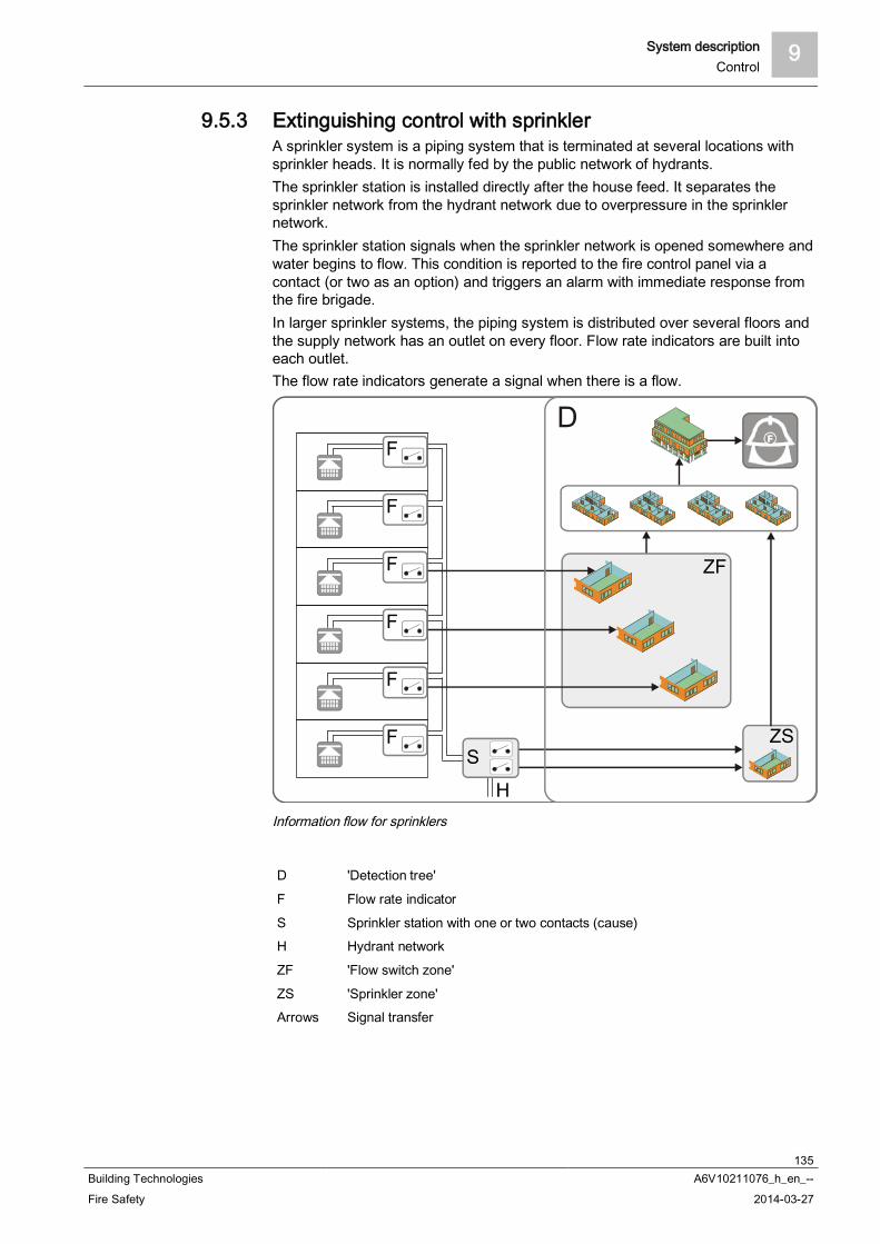
System description 9Control
135Building Technologies A6V10211076_h_en_--Fire Safety 2014-03-27
9.5.3 Extinguishing control with sprinklerA sprinkler system is a piping system that is terminated at several locations withsprinkler heads. It is normally fed by the public network of hydrants.The sprinkler station is installed directly after the house feed. It separates thesprinkler network from the hydrant network due to overpressure in the sprinklernetwork.The sprinkler station signals when the sprinkler network is opened somewhere andwater begins to flow. This condition is reported to the fire control panel via acontact (or two as an option) and triggers an alarm with immediate response fromthe fire brigade.In larger sprinkler systems, the piping system is distributed over several floors andthe supply network has an outlet on every floor. Flow rate indicators are built intoeach outlet.The flow rate indicators generate a signal when there is a flow.
Information flow for sprinklers
D 'Detection tree'
F Flow rate indicator
S Sprinkler station with one or two contacts (cause)H Hydrant network
ZF 'Flow switch zone'
ZS 'Sprinkler zone'Arrows Signal transfer
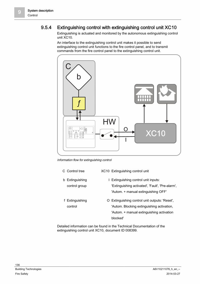
9 System descriptionControl
136Building Technologies A6V10211076_h_en_--Fire Safety 2014-03-27
9.5.4 Extinguishing control with extinguishing control unit XC10Extinguishing is actuated and monitored by the autonomous extinguishing controlunit XC10.An interface to the extinguishing control unit makes it possible to sendextinguishing control unit functions to the fire control panel, and to transmitcommands from the fire control panel to the extinguishing control unit.
Information flow for extinguishing control
C Control tree XC10 Extinguishing control unit
b Extinguishingcontrol group
I Extinguishing control unit inputs:'Extinguishing activated', 'Fault', 'Pre-alarm','Autom. + manual extinguishing OFF'
f Extinguishingcontrol
O Extinguishing control unit outputs: 'Reset','Autom. Blocking extinguishing activation,'Autom. + manual extinguishing activationblocked'
Detailed information can be found in the Technical Documentation of theextinguishing control unit XC10, document ID 008399.
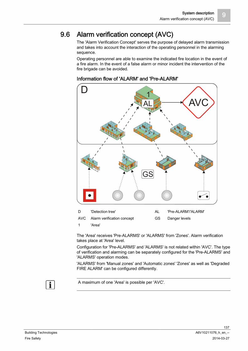
System description 9Alarm verification concept (AVC)
137Building Technologies A6V10211076_h_en_--Fire Safety 2014-03-27
9.6 Alarm verification concept (AVC)The 'Alarm Verification Concept' serves the purpose of delayed alarm transmissionand takes into account the interaction of the operating personnel in the alarmingsequence.Operating personnel are able to examine the indicated fire location in the event ofa fire alarm. In the event of a false alarm or minor incident the intervention of thefire brigade can be avoided.
Information flow of 'ALARM' and 'Pre-ALARM'
D 'Detection tree' AL 'Pre-ALARM'/'ALARM'
AVC Alarm verification concept GS Danger levels
1 'Area'
The 'Area' receives 'Pre-ALARMS' or 'ALARMS' from 'Zones'. Alarm verificationtakes place at 'Area' level.Configuration for 'Pre-ALARMS' and 'ALARMS' is not related within 'AVC'. The typeof verification and alarming can be separately configured for the 'Pre-ALARMS' and'ALARMS' operation modes.'ALARMS' from 'Manual zones' and 'Automatic zones' 'Zones' as well as 'DegradedFIRE ALARM' can be configured differently.
A maximum of one 'Area' is possible per 'AVC'.

9 System descriptionAlarm verification concept (AVC)
138Building Technologies A6V10211076_h_en_--Fire Safety 2014-03-27
9.6.1 Attendance checkShould an event ('Pre-ALARM', 'ALARM') arise, the operating personnel mayacknowledge presence within the time t1. After acknowledgement, the investigationtime t2 starts. If presence is not acknowledged within the given time t1, globalalarming is activated.
9.6.2 Investigation timeDuring the investigation time t2 the operating personnel may examine the indicatedsource of alarm and check the cause of the 'ALARM':
Or is it a real fire (emergency)? Is it a smoldering waste-paper basket (minor incident)? Has the installation detected a deceptive phenomenon (false alarm)?
In the event of a major incident (emergency), the nearest 'Manual call points' or<Alarm delay off> must be pressed. ''Immediate global alarming'' is then triggered.In the case of a minor incident or false alarm the operator may reset the 'ALARM'and cancel alarming.
If the 'ALARM' is not reset within the given time t2, 'Immediate global alarming' isactivated.
9.6.3 Example of a verification processAlarm verification proceeds as follows:
An alarm event activates local alarming and starts the time t1 for attendancemonitoring.
Operating personnel acknowledge 'ALARM' on the operating terminal prior tothe expiry of t1. Acknowledging normally silences local alarming (configurablefeature).
If there is no acknowledgement, global alarming is activated after the expiry of t1. After acknowledgement, the investigation time t2 starts. During time t2
operating personnel investigate the fire location.– In the case of a minor incident the operator resets the 'ALARM' at the
nearest operating terminal. The alarming process stops, and no globalalarming is activated.
– In the event of a fire, the nearest 'Manual call points' or <Alarm delay off>must be pressed. 'Manual call points' is triggered.
If there is no reset, 'Immediate global alarming' is also activated after the expiry oft2.
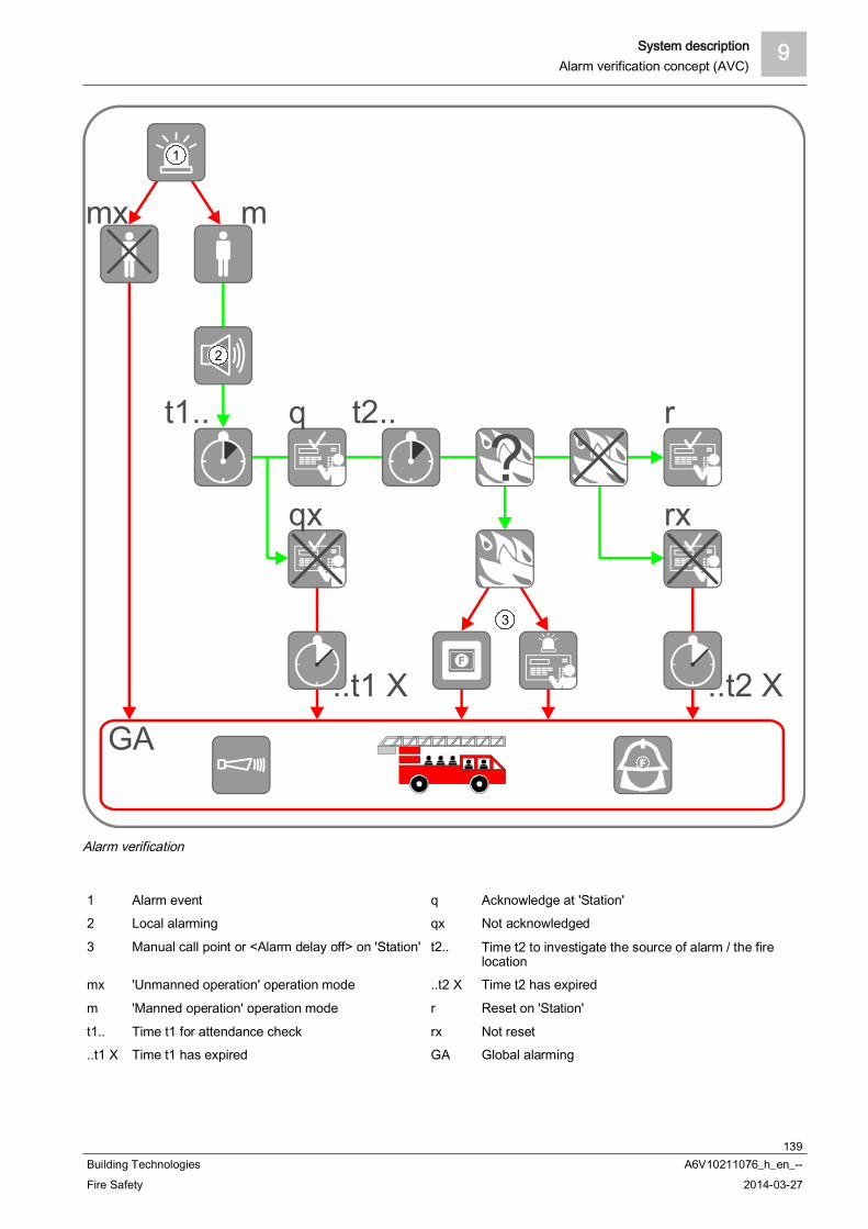
System description 9Alarm verification concept (AVC)
139Building Technologies A6V10211076_h_en_--Fire Safety 2014-03-27
t2..t1..
?
..t2 X..t1 X
1
mx m
2
q r
qx rx
GA
3
Alarm verification
1 Alarm event q Acknowledge at 'Station'2 Local alarming qx Not acknowledged
3 Manual call point or <Alarm delay off> on 'Station' t2.. Time t2 to investigate the source of alarm / the firelocation
mx 'Unmanned operation' operation mode ..t2 X Time t2 has expired
m 'Manned operation' operation mode r Reset on 'Station'
t1.. Time t1 for attendance check rx Not reset..t1 X Time t1 has expired GA Global alarming

9 System descriptionAlarm verification concept (AVC)
140Building Technologies A6V10211076_h_en_--Fire Safety 2014-03-27
9.6.4 Fire alarmingAlarming is controlled at 'Area' level. During alarming the alarming equipment isactivated, e.g. alarm devices and remote transmission devices.
Alarm devicesFor local and global alarming, acoustic alarm devices, strobes, digital outputs, etc.can be used. The tone of the alarm devices can be configured differently for localand global alarming (the alarm devices must be suitable for this).
Remote transmissionThe alarm message is transmitted to an intervention station. In the case of localalarming, this is usually the company fire brigade and for global alarm usually thestate fire brigade. A remote transmission device must be used to transmit alarmmessages via the public telephone network.
Information flow during alarming
AVC 'Alarm Verification Concept' f Alarming controlC 'Control tree' Y Local and global alarming
e 'Alarming control group'
The alarm devices and the remote transmission can be separately configured for: Alarm type (only with automatic zones)
– 'Pre-ALARM'– 'ALARM'
Zone type (only with 'ALARMS')– Manual alarm– Automatic alarm– Degraded fire alarm
Operating mode:– 'Manned operation'– 'Unmanned operation'
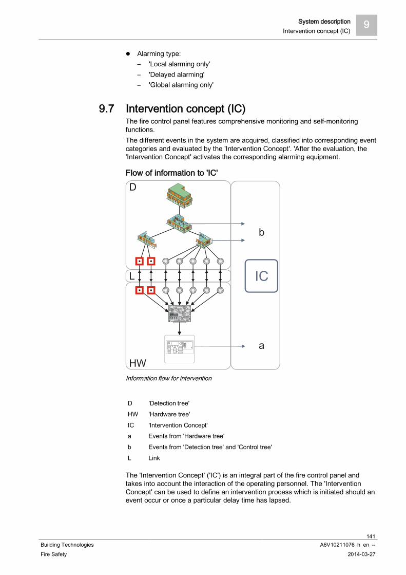
System description 9Intervention concept (IC)
141Building Technologies A6V10211076_h_en_--Fire Safety 2014-03-27
Alarming type:– 'Local alarming only'– 'Delayed alarming'– 'Global alarming only'
9.7 Intervention concept (IC)The fire control panel features comprehensive monitoring and self-monitoringfunctions.The different events in the system are acquired, classified into corresponding eventcategories and evaluated by the 'Intervention Concept'. 'After the evaluation, the'Intervention Concept' activates the corresponding alarming equipment.
Flow of information to 'IC'
Information flow for intervention
D 'Detection tree'
HW 'Hardware tree'
IC 'Intervention Concept'a Events from 'Hardware tree'
b Events from 'Detection tree' and 'Control tree'
L Link
The 'Intervention Concept' ('IC') is an integral part of the fire control panel andtakes into account the interaction of the operating personnel. The 'InterventionConcept' can be used to define an intervention process which is initiated should anevent occur or once a particular delay time has lapsed.
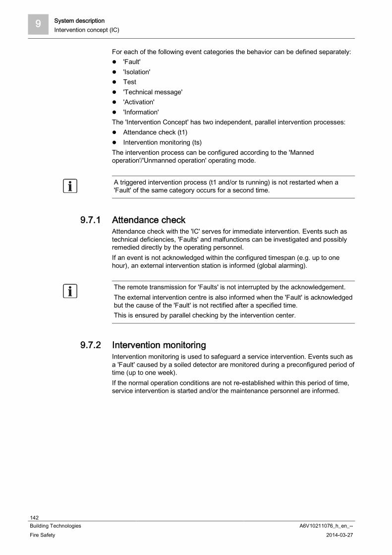
9 System descriptionIntervention concept (IC)
142Building Technologies A6V10211076_h_en_--Fire Safety 2014-03-27
For each of the following event categories the behavior can be defined separately: 'Fault' 'Isolation' Test 'Technical message' 'Activation' 'Information'
The 'Intervention Concept' has two independent, parallel intervention processes: Attendance check (t1) Intervention monitoring (ts)
The intervention process can be configured according to the 'Mannedoperation'/'Unmanned operation' operating mode.
A triggered intervention process (t1 and/or ts running) is not restarted when a'Fault' of the same category occurs for a second time.
9.7.1 Attendance checkAttendance check with the 'IC' serves for immediate intervention. Events such astechnical deficiencies, 'Faults' and malfunctions can be investigated and possiblyremedied directly by the operating personnel.If an event is not acknowledged within the configured timespan (e.g. up to onehour), an external intervention station is informed (global alarming).
The remote transmission for 'Faults' is not interrupted by the acknowledgement.The external intervention centre is also informed when the 'Fault' is acknowledgedbut the cause of the 'Fault' is not rectified after a specified time.This is ensured by parallel checking by the intervention center.
9.7.2 Intervention monitoringIntervention monitoring is used to safeguard a service intervention. Events such asa 'Fault' caused by a soiled detector are monitored during a preconfigured period oftime (up to one week).If the normal operation conditions are not re-established within this period of time,service intervention is started and/or the maintenance personnel are informed.
System description 9Intervention concept (IC)
143Building Technologies A6V10211076_h_en_--Fire Safety 2014-03-27
9.7.3 Example of an intervention process A 'Fault' activates local alarming and starts the time t1 for attendance
monitoring. Operating personnel acknowledge presence on the operating terminal prior to
the expiry of t1. Acknowledging silences the local alarming equipment. If thereis no acknowledgement, global alarming is activated after the expiry of t1.
The time ts for service intervention monitoring starts in parallel to the time t1. Ifthe 'Fault' is not eliminated prior to the expiry of ts, maintenance personnel arecalled up.
A triggered intervention process (t1 and/or ts running) is not restarted when a'Fault' of the same category occurs for a second time.
The figure below shows an exemplary intervention process for the 'Fault' eventcategory.
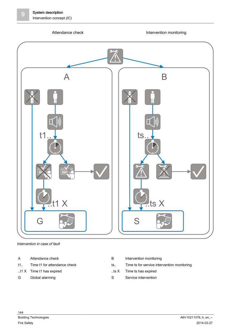
9 System descriptionIntervention concept (IC)
144Building Technologies A6V10211076_h_en_--Fire Safety 2014-03-27
Attendance check Intervention monitoring
!
! !
G
A B
..ts X..t1 X
t1.. ts..
S
Intervention in case of fault
A Attendance check B Intervention monitoring
t1.. Time t1 for attendance check ts.. Time ts for service intervention monitoring..t1 X Time t1 has expired ..ts X Time ts has expired
G Global alarming S Service intervention
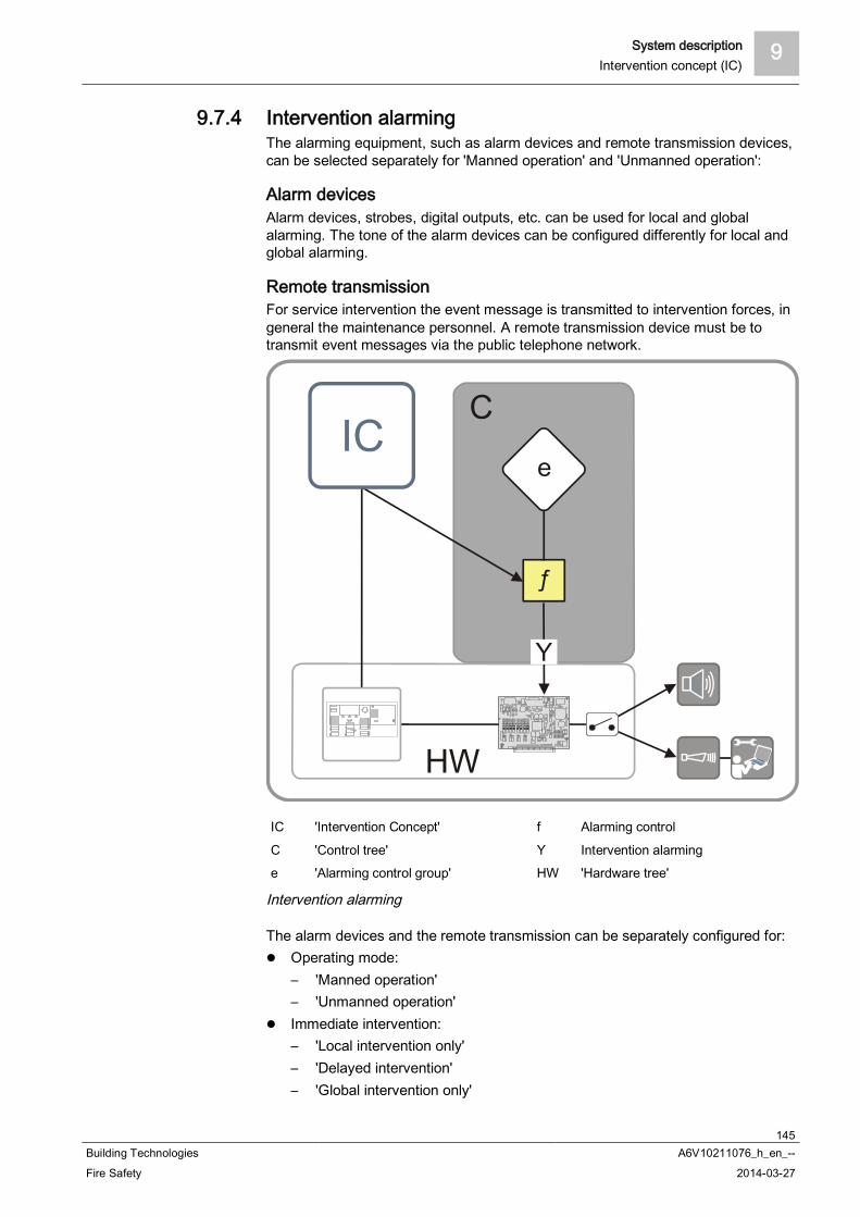
System description 9Intervention concept (IC)
145Building Technologies A6V10211076_h_en_--Fire Safety 2014-03-27
9.7.4 Intervention alarmingThe alarming equipment, such as alarm devices and remote transmission devices,can be selected separately for 'Manned operation' and 'Unmanned operation':
Alarm devicesAlarm devices, strobes, digital outputs, etc. can be used for local and globalalarming. The tone of the alarm devices can be configured differently for local andglobal alarming.
Remote transmissionFor service intervention the event message is transmitted to intervention forces, ingeneral the maintenance personnel. A remote transmission device must be totransmit event messages via the public telephone network.
IC 'Intervention Concept' f Alarming control
C 'Control tree' Y Intervention alarminge 'Alarming control group' HW 'Hardware tree'
Intervention alarming
The alarm devices and the remote transmission can be separately configured for: Operating mode:
– 'Manned operation'– 'Unmanned operation'
Immediate intervention:– 'Local intervention only'– 'Delayed intervention'– 'Global intervention only'
9 System descriptionEvents
146Building Technologies A6V10211076_h_en_--Fire Safety 2014-03-27
Service intervention:– 'Delayed intervention'– 'Direct intervention'
9.8 EventsSee also
Event memory [ 147]
9.8.1 Event categoriesThe fire detection system evaluates received signals and indicates them as events.Additionally, all events are stored and can be indicated in the 'Event memory' menuitem.There are the following event categories:
'ALARM' 'Pre-ALARM' 'Fault'
Detector, output and system errors 'Isolation'
Detector, output and system isolations Test
Inspection messages and conditions, test messages 'Technical message' 'Activation'
Activation of inputs and outputs 'Information'
Operating conditions, other system messages, information

System description 9Events
147Building Technologies A6V10211076_h_en_--Fire Safety 2014-03-27
9.8.2 Event status identificationEvent messages shown on the display are provided with an identification.This identification provides information on the status of the message.The following identifications are used:
0059/0360 AAAAA bbttt 06-05-19 00:00:01 ttt 06-05-25 08:48:29
06-05-23 09:25:36->Bbb 1
ZZZABCDEFGHI
ZZZABCDEFGHI
ZZZABCDEFGHI
A01 VVVVVGGGGGG
STST 01
06-05-22 08:16:05BF 2
GGGGGG/21
!
i
0060/0360 AAAAA bbttt 06-05-19 00:00:01 ttt 06-05-25 08:48:29
06-05-22 08:16:05BF 2
ZZZABCDEFGHI
ZZZABCDEFGHI
ZZZABCDEFGHI
GGGGGG/21
STST 01
06-05-22 07:22:01BF 2
GGGGGG/22+ +
Event status identification
Labeling Meaning
! Message not acknowledged
i Cause of message no longer available
No identification Message acknowledged
+ More than one detector is active
9.8.3 Event memoryAll events that have occurred in the fire detection installation are stored in the eventmemory . You can display a list of all events under the 'Event memory' menu item.The list is sorted chronologically and can be filtered by category, date and time.The figure below shows an example of a 'Event memory' list:
0008 / 0069 Eventsfrom 06-03-06 09-34-50 to 06-03-06 09-34-50
Station 01
06-03-06 10-34-50Zone 1306-03-06 10-34-50Autom. 13
Office 21
A02 Window side
OFF
OFF
SelectEvent category
SelectDate/time range
MoreOptions
See also Select events [ 59]
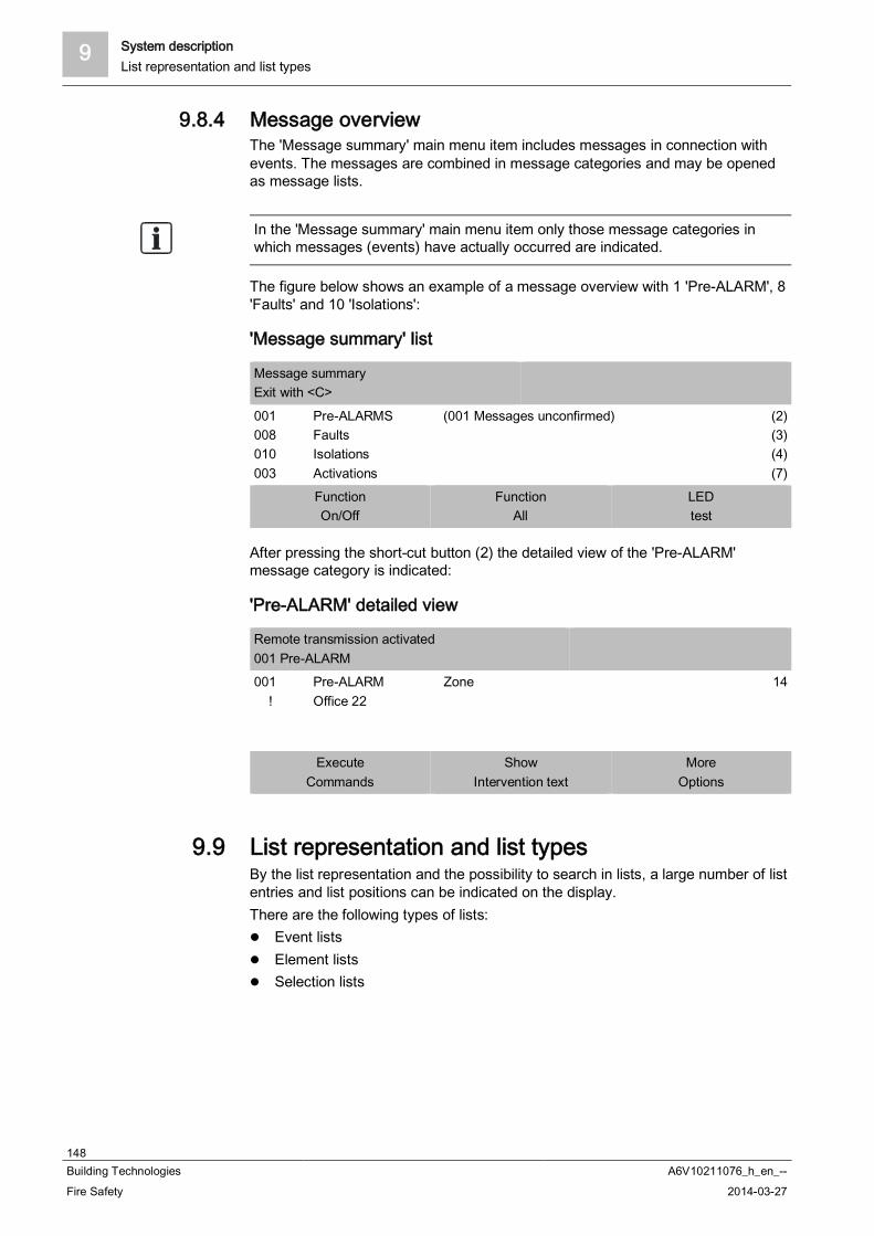
9 System descriptionList representation and list types
148Building Technologies A6V10211076_h_en_--Fire Safety 2014-03-27
9.8.4 Message overviewThe 'Message summary' main menu item includes messages in connection withevents. The messages are combined in message categories and may be openedas message lists.
In the 'Message summary' main menu item only those message categories inwhich messages (events) have actually occurred are indicated.
The figure below shows an example of a message overview with 1 'Pre-ALARM', 8'Faults' and 10 'Isolations':
'Message summary' list
Message summaryExit with <C>
001008010003
Pre-ALARMSFaultsIsolationsActivations
(001 Messages unconfirmed) (2)(3)(4)(7)
FunctionOn/Off
FunctionAll
LEDtest
After pressing the short-cut button (2) the detailed view of the 'Pre-ALARM'message category is indicated:
'Pre-ALARM' detailed view
Remote transmission activated001 Pre-ALARM001 !
Pre-ALARMOffice 22
Zone 14
ExecuteCommands
ShowIntervention text
MoreOptions
9.9 List representation and list typesBy the list representation and the possibility to search in lists, a large number of listentries and list positions can be indicated on the display.There are the following types of lists:
Event lists Element lists Selection lists

System description 9List representation and list types
149Building Technologies A6V10211076_h_en_--Fire Safety 2014-03-27
9.9.1 Event listsEvent lists include events that have occurred in the fire detection installations andbelong to different categories.In the 'Message summary' main menu item messages are combined in eventcategories. These event categories may be opened as an event list.
In the 'Message summary' main menu item only those event categories areindicated in which events have actually occurred.
In accordance with the event categories, there are the following event lists: 'ALARM' 'Pre-ALARM' 'Fault' 'Isolation' Test 'Technical message' 'Activation' 'Information'
All events are also included in the event list in the 'Event memory'. This 'Eventmemory' list has a different layout as well as additional functions. For this reason,a separate chapter 'Event memory' is included.
The figure below shows an example of an 'Isolation' event list:
Waiting for confirmation RT002 IsolationsAutom.
Sounder 2
Zone OFF001
OFF002
ExecuteCommands
ShowIntervention text
MoreOptions
See also Event memory [ 147]

9 System descriptionList representation and list types
150Building Technologies A6V10211076_h_en_--Fire Safety 2014-03-27
9.9.2 Element listsElement lists contain elements of the installation, as well as element data, e.g.configuration data.An element list is indicated as e.g. the result of an element search.The figure below shows a sample 'Element search':
025 Elements
stationAreaPMINetwork
1111
ExecuteCommands
Execute commandsTopology
Example of an element list
Details of Station 1
=============ElementId:Discipline:ElementType
Element Properties1/1FIREPanelFc2020Elem
==============
JumpBack
Example data of an element
9.9.3 Selection listsSelection lists are used to select actions or categories.There are selection lists for the following actions or categories:
Commands Options Elements Events (to filter the event memory)
The table below shows an example of a 'Select command' selection list:
Select command
Set customer textONOFFOFF/timerActivate
(1)(2)(3)(4)(5)
System description 9Version display for station / configuration data
151Building Technologies A6V10211076_h_en_--Fire Safety 2014-03-27
9.10 Version display for station / configuration dataYou can display information about the 'Station' and the configuration data versionin the topology tree.A description of the calling-up of the indication can be found in the chapter inaccount.
See also Show version [ 95]
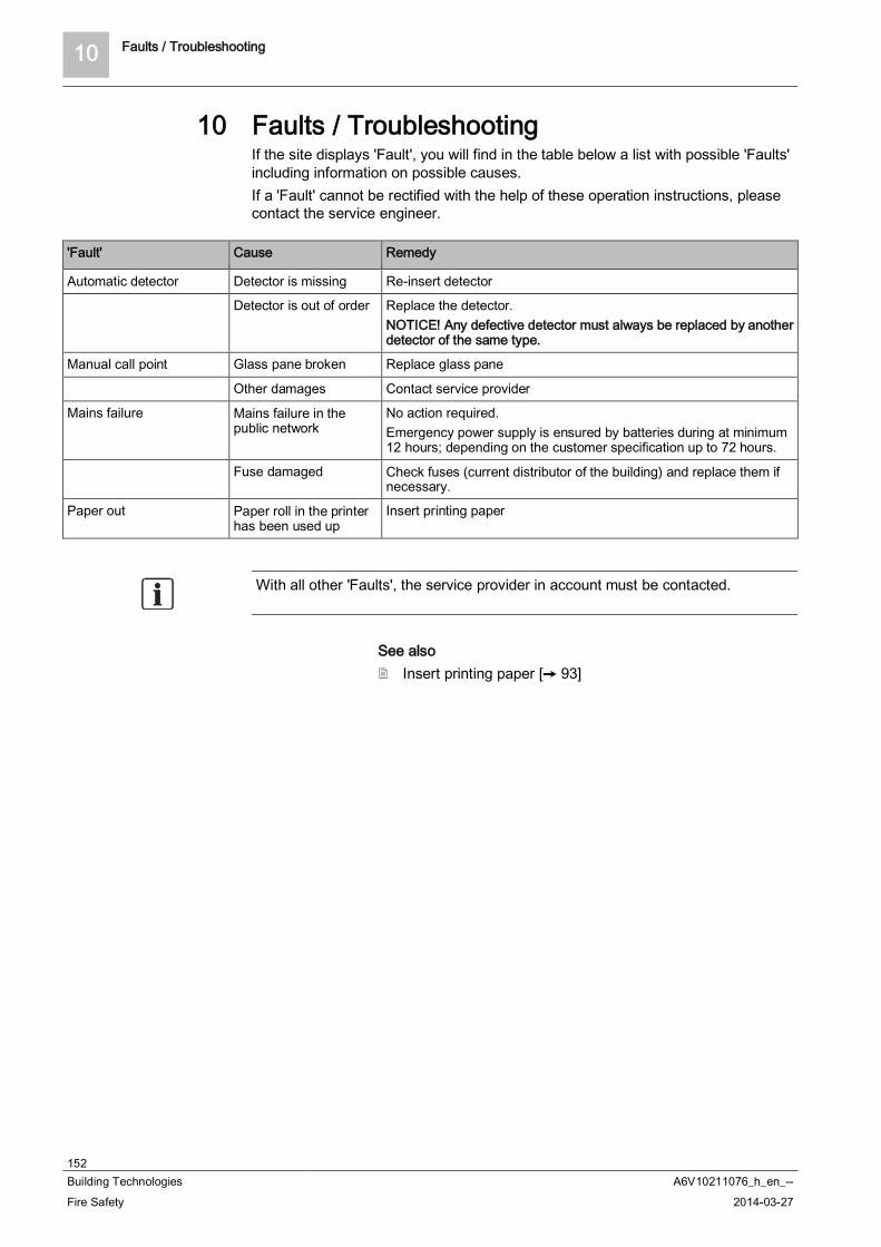
10 Faults / Troubleshooting
152Building Technologies A6V10211076_h_en_--Fire Safety 2014-03-27
10 Faults / TroubleshootingIf the site displays 'Fault', you will find in the table below a list with possible 'Faults'including information on possible causes.If a 'Fault' cannot be rectified with the help of these operation instructions, pleasecontact the service engineer.
'Fault' Cause Remedy
Automatic detector Detector is missing Re-insert detector
Detector is out of order Replace the detector.NOTICE! Any defective detector must always be replaced by anotherdetector of the same type.
Manual call point Glass pane broken Replace glass pane
Other damages Contact service provider
Mains failure Mains failure in thepublic network
No action required.Emergency power supply is ensured by batteries during at minimum12 hours; depending on the customer specification up to 72 hours.
Fuse damaged Check fuses (current distributor of the building) and replace them ifnecessary.
Paper out Paper roll in the printerhas been used up
Insert printing paper
With all other 'Faults', the service provider in account must be contacted.
See also Insert printing paper [ 93]
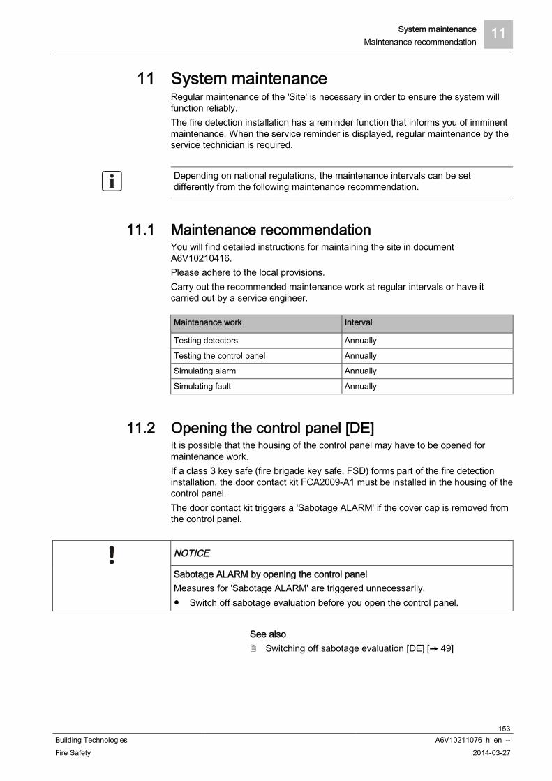
System maintenance 11Maintenance recommendation
153Building Technologies A6V10211076_h_en_--Fire Safety 2014-03-27
11 System maintenanceRegular maintenance of the 'Site' is necessary in order to ensure the system willfunction reliably.The fire detection installation has a reminder function that informs you of imminentmaintenance. When the service reminder is displayed, regular maintenance by theservice technician is required.
Depending on national regulations, the maintenance intervals can be setdifferently from the following maintenance recommendation.
11.1 Maintenance recommendationYou will find detailed instructions for maintaining the site in documentA6V10210416.Please adhere to the local provisions.Carry out the recommended maintenance work at regular intervals or have itcarried out by a service engineer.
Maintenance work Interval
Testing detectors Annually
Testing the control panel Annually
Simulating alarm Annually
Simulating fault Annually
11.2 Opening the control panel [DE]It is possible that the housing of the control panel may have to be opened formaintenance work.If a class 3 key safe (fire brigade key safe, FSD) forms part of the fire detectioninstallation, the door contact kit FCA2009-A1 must be installed in the housing of thecontrol panel.The door contact kit triggers a 'Sabotage ALARM' if the cover cap is removed fromthe control panel.
NOTICE
Sabotage ALARM by opening the control panelMeasures for 'Sabotage ALARM' are triggered unnecessarily.
Switch off sabotage evaluation before you open the control panel.
See also Switching off sabotage evaluation [DE] [ 49]
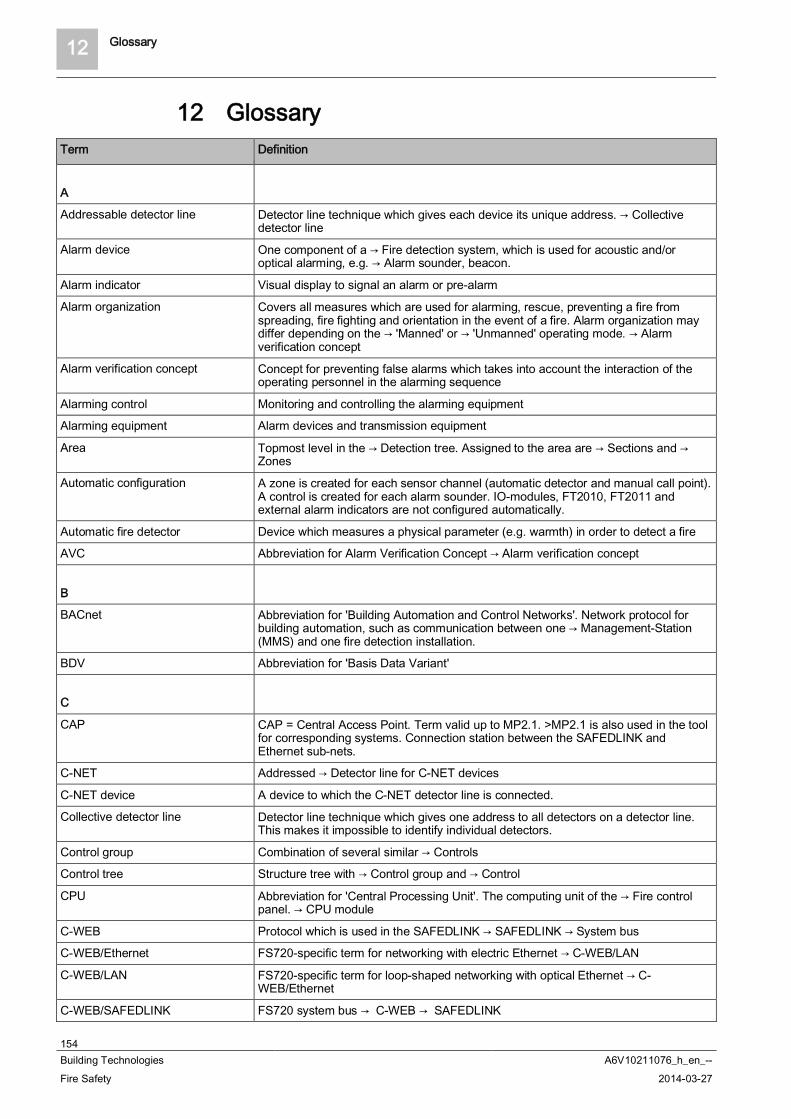
12 Glossary
154Building Technologies A6V10211076_h_en_--Fire Safety 2014-03-27
12 GlossaryTerm Definition
A
Addressable detector line Detector line technique which gives each device its unique address. Collectivedetector line
Alarm device One component of a Fire detection system, which is used for acoustic and/oroptical alarming, e.g. Alarm sounder, beacon.
Alarm indicator Visual display to signal an alarm or pre-alarm
Alarm organization Covers all measures which are used for alarming, rescue, preventing a fire fromspreading, fire fighting and orientation in the event of a fire. Alarm organization maydiffer depending on the 'Manned' or 'Unmanned' operating mode. Alarmverification concept
Alarm verification concept Concept for preventing false alarms which takes into account the interaction of theoperating personnel in the alarming sequence
Alarming control Monitoring and controlling the alarming equipment
Alarming equipment Alarm devices and transmission equipment
Area Topmost level in the Detection tree. Assigned to the area are Sections and Zones
Automatic configuration A zone is created for each sensor channel (automatic detector and manual call point).A control is created for each alarm sounder. IO-modules, FT2010, FT2011 andexternal alarm indicators are not configured automatically.
Automatic fire detector Device which measures a physical parameter (e.g. warmth) in order to detect a fire
AVC Abbreviation for Alarm Verification Concept Alarm verification concept
B
BACnet Abbreviation for 'Building Automation and Control Networks'. Network protocol forbuilding automation, such as communication between one Management-Station(MMS) and one fire detection installation.
BDV Abbreviation for 'Basis Data Variant'
C
CAP CAP = Central Access Point. Term valid up to MP2.1. >MP2.1 is also used in the toolfor corresponding systems. Connection station between the SAFEDLINK andEthernet sub-nets.
C-NET Addressed Detector line for C-NET devices
C-NET device A device to which the C-NET detector line is connected.
Collective detector line Detector line technique which gives one address to all detectors on a detector line.This makes it impossible to identify individual detectors.
Control group Combination of several similar Controls
Control tree Structure tree with Control group and Control
CPU Abbreviation for 'Central Processing Unit'. The computing unit of the Fire controlpanel. CPU module
C-WEB Protocol which is used in the SAFEDLINK SAFEDLINK System bus
C-WEB/Ethernet FS720-specific term for networking with electric Ethernet C-WEB/LAN
C-WEB/LAN FS720-specific term for loop-shaped networking with optical Ethernet C-WEB/Ethernet
C-WEB/SAFEDLINK FS720 system bus C-WEB SAFEDLINK
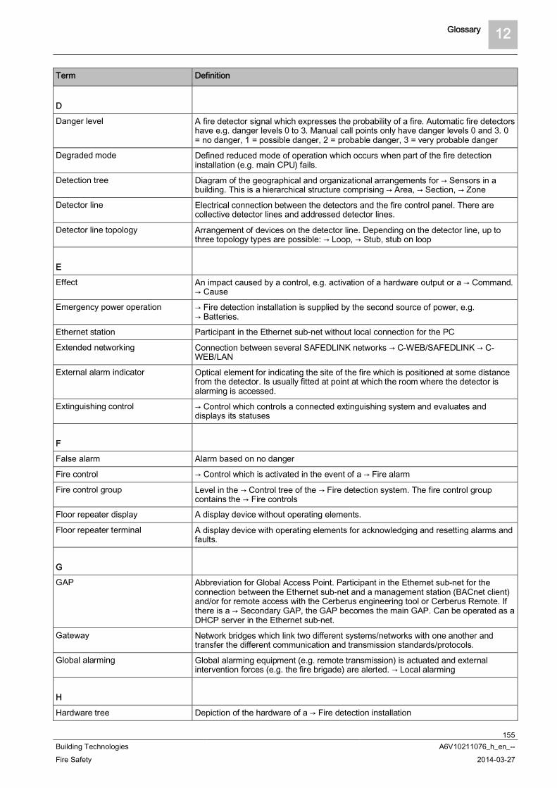
Glossary 12
155Building Technologies A6V10211076_h_en_--Fire Safety 2014-03-27
Term Definition
D
Danger level A fire detector signal which expresses the probability of a fire. Automatic fire detectorshave e.g. danger levels 0 to 3. Manual call points only have danger levels 0 and 3. 0= no danger, 1 = possible danger, 2 = probable danger, 3 = very probable danger
Degraded mode Defined reduced mode of operation which occurs when part of the fire detectioninstallation (e.g. main CPU) fails.
Detection tree Diagram of the geographical and organizational arrangements for Sensors in abuilding. This is a hierarchical structure comprising Area, Section, Zone
Detector line Electrical connection between the detectors and the fire control panel. There arecollective detector lines and addressed detector lines.
Detector line topology Arrangement of devices on the detector line. Depending on the detector line, up tothree topology types are possible: Loop, Stub, stub on loop
E
Effect An impact caused by a control, e.g. activation of a hardware output or a Command. Cause
Emergency power operation Fire detection installation is supplied by the second source of power, e.g. Batteries.
Ethernet station Participant in the Ethernet sub-net without local connection for the PC
Extended networking Connection between several SAFEDLINK networks C-WEB/SAFEDLINK C-WEB/LAN
External alarm indicator Optical element for indicating the site of the fire which is positioned at some distancefrom the detector. Is usually fitted at point at which the room where the detector isalarming is accessed.
Extinguishing control Control which controls a connected extinguishing system and evaluates anddisplays its statuses
F
False alarm Alarm based on no danger
Fire control Control which is activated in the event of a Fire alarm
Fire control group Level in the Control tree of the Fire detection system. The fire control groupcontains the Fire controls
Floor repeater display A display device without operating elements.
Floor repeater terminal A display device with operating elements for acknowledging and resetting alarms andfaults.
G
GAP Abbreviation for Global Access Point. Participant in the Ethernet sub-net for theconnection between the Ethernet sub-net and a management station (BACnet client)and/or for remote access with the Cerberus engineering tool or Cerberus Remote. Ifthere is a Secondary GAP, the GAP becomes the main GAP. Can be operated as aDHCP server in the Ethernet sub-net.
Gateway Network bridges which link two different systems/networks with one another andtransfer the different communication and transmission standards/protocols.
Global alarming Global alarming equipment (e.g. remote transmission) is actuated and externalintervention forces (e.g. the fire brigade) are alerted. Local alarming
H
Hardware tree Depiction of the hardware of a Fire detection installation
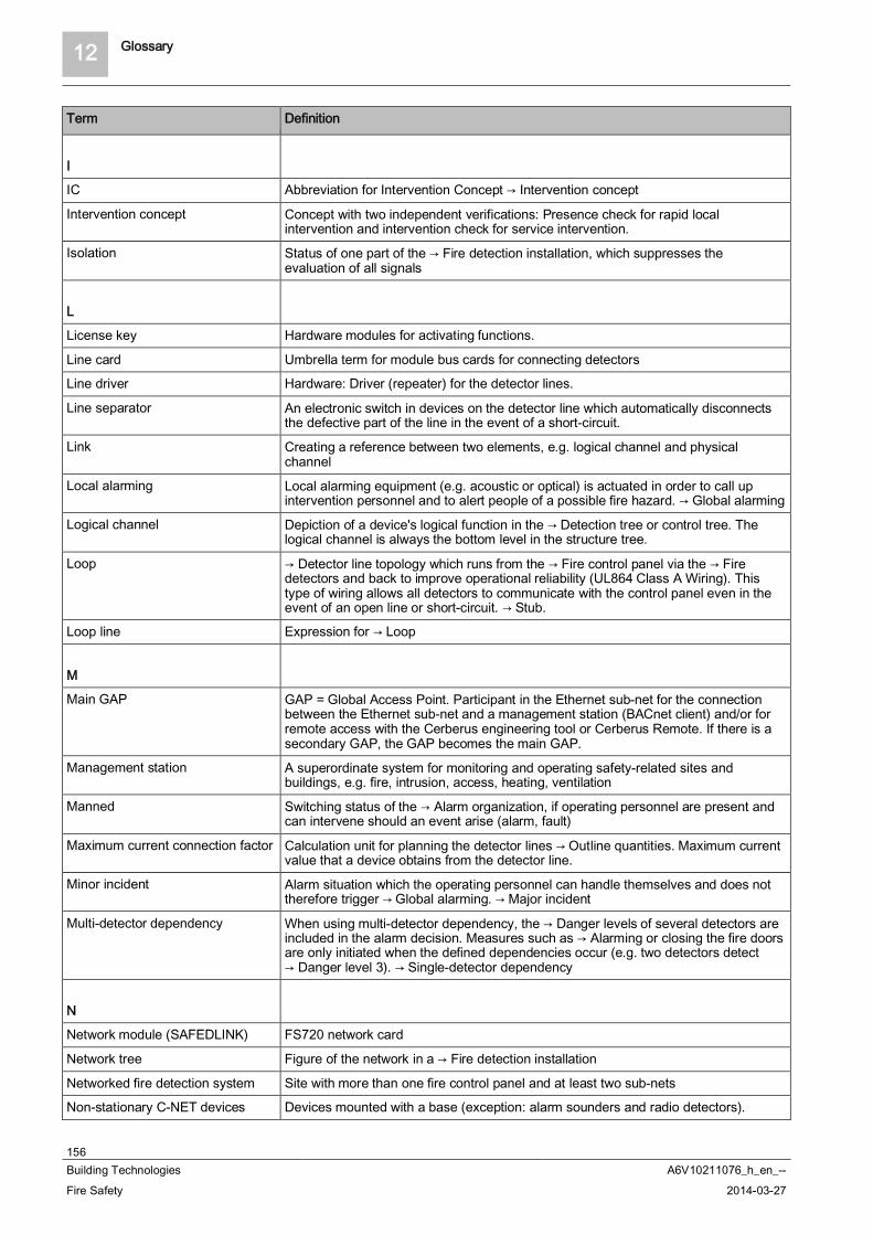
12 Glossary
156Building Technologies A6V10211076_h_en_--Fire Safety 2014-03-27
Term Definition
I
IC Abbreviation for Intervention Concept Intervention concept
Intervention concept Concept with two independent verifications: Presence check for rapid localintervention and intervention check for service intervention.
Isolation Status of one part of the Fire detection installation, which suppresses theevaluation of all signals
L
License key Hardware modules for activating functions.
Line card Umbrella term for module bus cards for connecting detectors
Line driver Hardware: Driver (repeater) for the detector lines.
Line separator An electronic switch in devices on the detector line which automatically disconnectsthe defective part of the line in the event of a short-circuit.
Link Creating a reference between two elements, e.g. logical channel and physicalchannel
Local alarming Local alarming equipment (e.g. acoustic or optical) is actuated in order to call upintervention personnel and to alert people of a possible fire hazard. Global alarming
Logical channel Depiction of a device's logical function in the Detection tree or control tree. Thelogical channel is always the bottom level in the structure tree.
Loop Detector line topology which runs from the Fire control panel via the Firedetectors and back to improve operational reliability (UL864 Class A Wiring). Thistype of wiring allows all detectors to communicate with the control panel even in theevent of an open line or short-circuit. Stub.
Loop line Expression for Loop
M
Main GAP GAP = Global Access Point. Participant in the Ethernet sub-net for the connectionbetween the Ethernet sub-net and a management station (BACnet client) and/or forremote access with the Cerberus engineering tool or Cerberus Remote. If there is asecondary GAP, the GAP becomes the main GAP.
Management station A superordinate system for monitoring and operating safety-related sites andbuildings, e.g. fire, intrusion, access, heating, ventilation
Manned Switching status of the Alarm organization, if operating personnel are present andcan intervene should an event arise (alarm, fault)
Maximum current connection factor Calculation unit for planning the detector lines Outline quantities. Maximum currentvalue that a device obtains from the detector line.
Minor incident Alarm situation which the operating personnel can handle themselves and does nottherefore trigger Global alarming. Major incident
Multi-detector dependency When using multi-detector dependency, the Danger levels of several detectors areincluded in the alarm decision. Measures such as Alarming or closing the fire doorsare only initiated when the defined dependencies occur (e.g. two detectors detect
Danger level 3). Single-detector dependency
N
Network module (SAFEDLINK) FS720 network card
Network tree Figure of the network in a Fire detection installation
Networked fire detection system Site with more than one fire control panel and at least two sub-nets
Non-stationary C-NET devices Devices mounted with a base (exception: alarm sounders and radio detectors).

Glossary 12
157Building Technologies A6V10211076_h_en_--Fire Safety 2014-03-27
Term Definition
Normal operation The Fire detection installation is supplied with mains voltage.
Normally closed contact (NC) Opens a power circuit when activated. Normally open contact (NO)
Normally open contact (NO) Closes a power circuit when activated Normally closed contact (NC)
O
Outline quantities Defines the number of permissible elements of one type in a system. For example,maximum number of devices on a Detector line.
P
Parameter set Defined detector behavior, e.g. in terms of sensitivity, resistance to deceptivephenomena, response time. Detectors can be operated with different parameter sets.
Physical channel Depiction of a device's physical function in the Hardware tree. The physical channelis the bottom level in the hardware tree.
Pre-alarm Stage before an Alarm for information early on should an event occur.
Pre-configuration A sub-configuration of the Hardware tree, Detection tree and Control treeproduced before commissioning the Fire detection installation.
Q
Quiescent current connection factor Factor for the current that a device obtains from the detector line when in quiescentcondition
R
Radio gateway Interface converter for converting from detector line protocol to radio
Remote transmission Transmission of information based on events to a remote station, e.g. the fire brigade,by means of an RT device. This is usually performed via the public telephonenetwork.
Renovation mode Mode of operation of the Zone for maintaining a minimum detection ability duringrenovation work. In renovation mode, the detectors are operated at low sensitivity.
Router station Participant in the SAFEDLINK sub-net for the connection between the SAFEDLINKsub-net and the Ethernet sub-net (C-WEB/LAN) via the Ethernet switch (MM)FN2008-A1.
RT Abbreviation for Remote transmission
S
SAFEDLINK Physical network of an FS720 fire detection system with the Network module(SAFEDLINK) and the network cable
SAFEDLINK station Participant in the SAFEDLINK sub-net with local connection for the PC
Secondary GAP GAP = Global Access Point. Participant in the Ethernet sub-net, in redundancy to themain GAP, for the connection between the Ethernet sub-net and a standbymanagement station (BACnet client) and/or for remote access with the Cerberusengineering tool or Cerberus Remote. Cannot be operated as a DHCP server in theEthernet sub-net.
Section Level in the Detection tree of the Fire detection system. The Section isassigned to the Area. It is used to combine Zones.
Separator connector factor Specifies whether a device on the detector line features a line separator.
Single-detector dependency With single-detector dependency, the alarm decision depends on the Danger levelof one detector. The first detector in the Zone which detects the corresponding
Danger level, triggers a Fire alarm. Multi-detector dependency
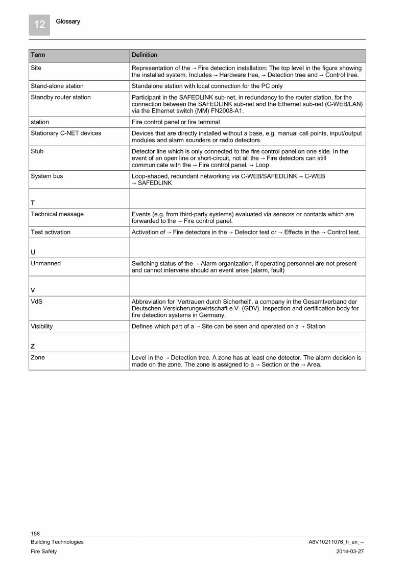
12 Glossary
158Building Technologies A6V10211076_h_en_--Fire Safety 2014-03-27
Term Definition
Site Representation of the Fire detection installation: The top level in the figure showingthe installed system. Includes Hardware tree, Detection tree and Control tree.
Stand-alone station Standalone station with local connection for the PC only
Standby router station Participant in the SAFEDLINK sub-net, in redundancy to the router station, for theconnection between the SAFEDLINK sub-net and the Ethernet sub-net (C-WEB/LAN)via the Ethernet switch (MM) FN2008-A1.
station Fire control panel or fire terminal
Stationary C-NET devices Devices that are directly installed without a base, e.g. manual call points, input/outputmodules and alarm sounders or radio detectors.
Stub Detector line which is only connected to the fire control panel on one side. In theevent of an open line or short-circuit, not all the Fire detectors can stillcommunicate with the Fire control panel. Loop
System bus Loop-shaped, redundant networking via C-WEB/SAFEDLINK C-WEB SAFEDLINK
T
Technical message Events (e.g. from third-party systems) evaluated via sensors or contacts which areforwarded to the Fire control panel.
Test activation Activation of Fire detectors in the Detector test or Effects in the Control test.
U
Unmanned Switching status of the Alarm organization, if operating personnel are not presentand cannot intervene should an event arise (alarm, fault)
V
VdS Abbreviation for 'Vertrauen durch Sicherheit', a company in the Gesamtverband derDeutschen Versicherungswirtschaft e.V. (GDV). Inspection and certification body forfire detection systems in Germany.
Visibility Defines which part of a Site can be seen and operated on a Station
Z
Zone Level in the Detection tree. A zone has at least one detector. The alarm decision ismade on the zone. The zone is assigned to a Section or the Area.
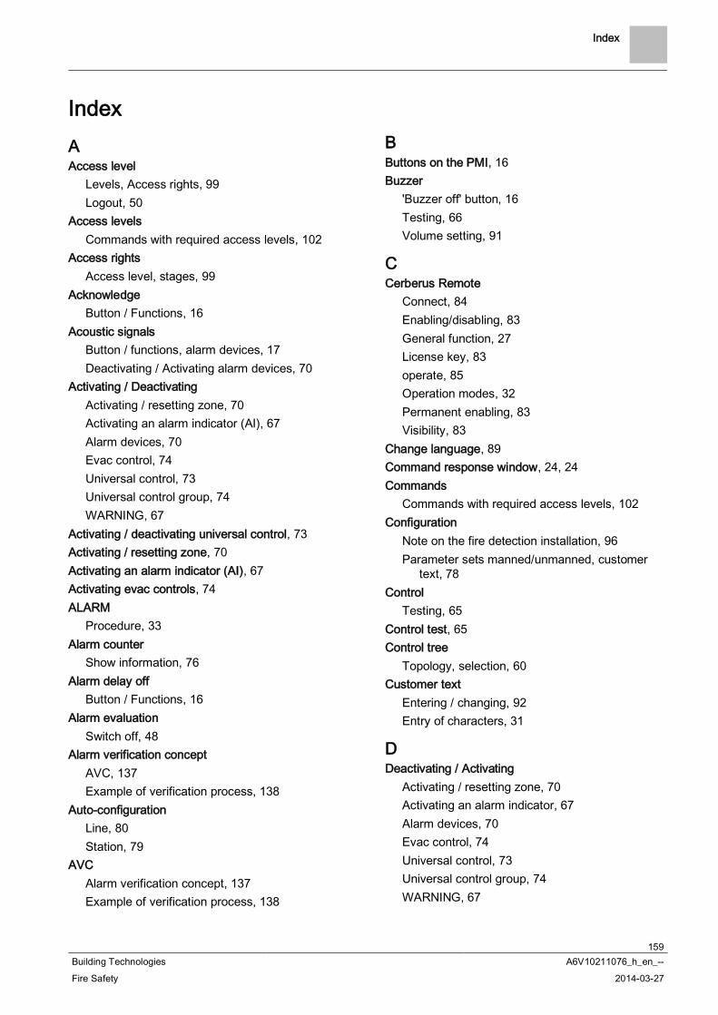
Index
159Building Technologies A6V10211076_h_en_--Fire Safety 2014-03-27
IndexAAccess level
Levels, Access rights, 99Logout, 50
Access levelsCommands with required access levels, 102
Access rightsAccess level, stages, 99
AcknowledgeButton / Functions, 16
Acoustic signalsButton / functions, alarm devices, 17Deactivating / Activating alarm devices, 70
Activating / DeactivatingActivating / resetting zone, 70Activating an alarm indicator (AI), 67Alarm devices, 70Evac control, 74Universal control, 73Universal control group, 74WARNING, 67
Activating / deactivating universal control, 73Activating / resetting zone, 70Activating an alarm indicator (AI), 67Activating evac controls, 74ALARM
Procedure, 33Alarm counter
Show information, 76Alarm delay off
Button / Functions, 16Alarm evaluation
Switch off, 48Alarm verification concept
AVC, 137Example of verification process, 138
Auto-configurationLine, 80Station, 79
AVCAlarm verification concept, 137Example of verification process, 138
BButtons on the PMI, 16Buzzer
'Buzzer off' button, 16Testing, 66Volume setting, 91
CCerberus Remote
Connect, 84Enabling/disabling, 83General function, 27License key, 83operate, 85Operation modes, 32Permanent enabling, 83Visibility, 83
Change language, 89Command response window, 24, 24Commands
Commands with required access levels, 102Configuration
Note on the fire detection installation, 96Parameter sets manned/unmanned, customer
text, 78Control
Testing, 65Control test, 65Control tree
Topology, selection, 60Customer text
Entering / changing, 92Entry of characters, 31
DDeactivating / Activating
Activating / resetting zone, 70Activating an alarm indicator, 67Alarm devices, 70Evac control, 74Universal control, 73Universal control group, 74WARNING, 67

Index
160Building Technologies A6V10211076_h_en_--Fire Safety 2014-03-27
Deactivating / Activating alarm devices, 70Button 'Acoustic signals', 70
Detection treeTopology, selection, 60
DetectorSwitching off / Switching on, 40Temporary switching-off, 43Testing, 64
Detector testCommands, 64
Display, 21Brightness setting, 91Displaying variants, 21Extended view / Switching over, 23Fire department view, 23How displays are represented in the document,
10Input field, 24Normal view, 22
Download centerURL, 8
EElements
List of elements, 109Search by address / category, 61
Enable, 87Entering characters
Keypad, 31Entering commands
Function-oriented, 58Hiding confirmation, 58Object-oriented, 56Principles, 54
Entry of charactersNumbers, letters (customer text), 31
Event memory, 88Deleting, 88Navigating, 88Polling, 88Sort, filter list, 147
EventsCategories, 146Event memory, 88Labeling, 147Selecting, 59
Expanded visibilityVisibility, 101
Expiry reminder, 45
FFaults
List, cause / rectification, 152Favorites, 30Fire department view, 23
GGlobal alarming, 113
HHardware tree
Topology, selection, 60Hardware version
Module, 78Polling, 77Station, 77
IIndicators
Buzzer test, 66Display and test LEDs, 66
Input fieldDisplay with window and input field, 24
Installation testWARNING, 65
KKey switch, 25Keypad
Entry of characters, 31
LLEDs
Colors, 25Testing, 66
License keyCerberus Remote, 83
LineAuto-configuration, 80
Local alarming, 113Log in, 49Login, 49Logout, 50, 50
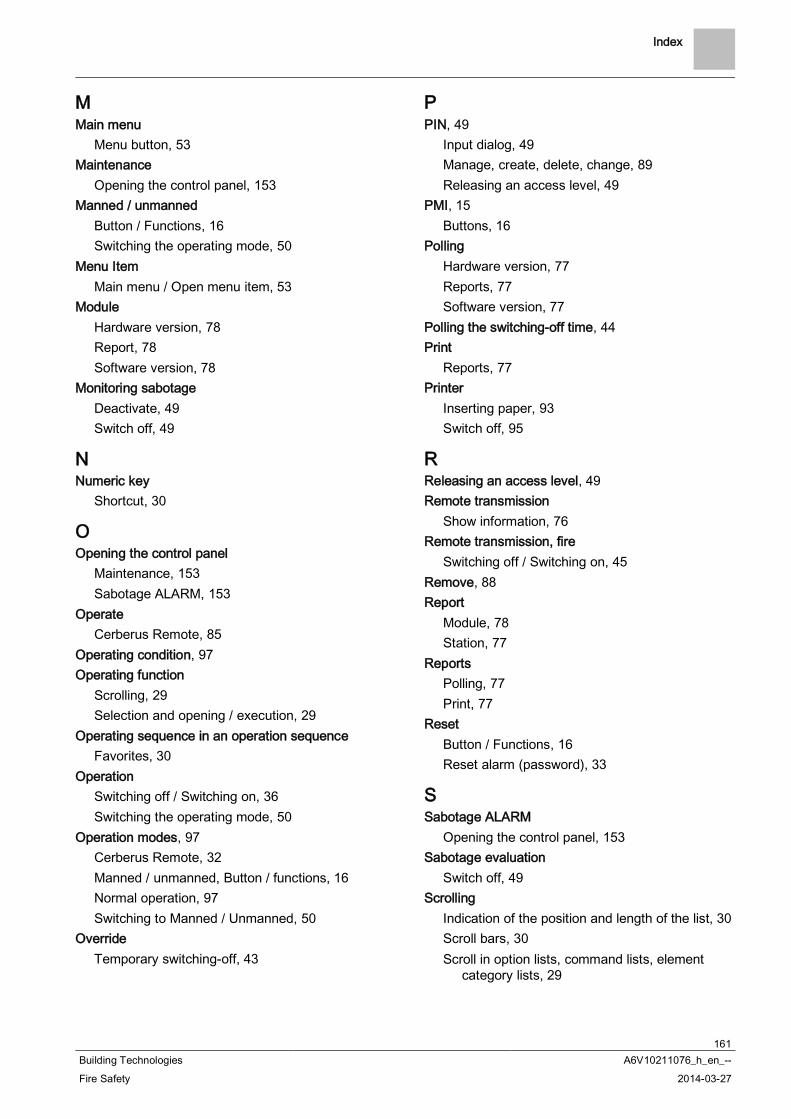
Index
161Building Technologies A6V10211076_h_en_--Fire Safety 2014-03-27
MMain menu
Menu button, 53Maintenance
Opening the control panel, 153Manned / unmanned
Button / Functions, 16Switching the operating mode, 50
Menu ItemMain menu / Open menu item, 53
ModuleHardware version, 78Report, 78Software version, 78
Monitoring sabotageDeactivate, 49Switch off, 49
NNumeric key
Shortcut, 30
OOpening the control panel
Maintenance, 153Sabotage ALARM, 153
OperateCerberus Remote, 85
Operating condition, 97Operating function
Scrolling, 29Selection and opening / execution, 29
Operating sequence in an operation sequenceFavorites, 30
OperationSwitching off / Switching on, 36Switching the operating mode, 50
Operation modes, 97Cerberus Remote, 32Manned / unmanned, Button / functions, 16Normal operation, 97Switching to Manned / Unmanned, 50
OverrideTemporary switching-off, 43
PPIN, 49
Input dialog, 49Manage, create, delete, change, 89Releasing an access level, 49
PMI, 15Buttons, 16
PollingHardware version, 77Reports, 77Software version, 77
Polling the switching-off time, 44Print
Reports, 77Printer
Inserting paper, 93Switch off, 95
RReleasing an access level, 49Remote transmission
Show information, 76Remote transmission, fire
Switching off / Switching on, 45Remove, 88Report
Module, 78Station, 77
ReportsPolling, 77Print, 77
ResetButton / Functions, 16Reset alarm (password), 33
SSabotage ALARM
Opening the control panel, 153Sabotage evaluation
Switch off, 49Scrolling
Indication of the position and length of the list, 30Scroll bars, 30Scroll in option lists, command lists, element
category lists, 29

Index
162Building Technologies A6V10211076_h_en_--Fire Safety 2014-03-27
Service reminderSystem maintenance, 153
Setting the date, 91Setting the system time, 91Setting time and date, 91Settings / Administration
Setting time and date, 91Shortcut, 30Show information
Alarm counter, remote transmission, 76Software version
Module, 78Polling, 77Station, 77
StandbyVisibility, 101
StationAuto-configuration, 79Enable smartphone, 87Hardware version, 77Removing a smartphone, 88Report, 77Software version, 77
Switch offAlarm evaluation, 48Sabotage evaluation, 49
Switch off alarm delay, 33Switching off / Switching on, 36
Detector, 40Remote transmission, fire, 45Temporary switching-off, 43WARNING, 36
Switching on / Switching offDetector, 40Remote transmission, fire, 45Temporary switching-off, 43WARNING, 36
System maintenanceService reminder, 153
TTemporary switching-off, 43
Expiry reminder, 45Override, 43Polling the switching-off time, 44Section, duration, 43
TestingControl, 65
Time settingSetting time and date, 91
Topology, 113Selecting an element, 60
VVersion
Indicators, 95Visibility
Definition, 100expanded visibility, 101Standby, 101

Index
163Building Technologies A6V10211076_h_en_--Fire Safety 2014-03-27

Issued bySiemens Switzerland LtdInfrastructure & Cities SectorBuilding Technologies DivisionInternational HeadquartersGubelstrasse 22CH-6301 ZugTel. +41 41-724 24 24www.siemens.com/buildingtechnologies
© 2008-2014 Copyright Siemens Switzerland LtdTechnical specifications and availability subject to change without notice.
Document ID A6V10211076_h_en_-- Manual FS720Edition 2014-03-27 Register 7