EXPERIMENTAL EVALUATION OF VORTEX GENERATOR USAGE …
24
EXPERIMENTAL EVALUATION OF VORTEX GENERATOR USAGE TO REDUCE THE COEFFICIENT OF DRAG OF PROTON SAGA CAR AIZAD AYASYI B AB GHAFAR A thesis submitted in partial fulfillment of the requirements for the award of the degree of Bachelor of Mechanical Engineering Faculty of Mechanical Engineering Universiti Malaysia Pahang UNVERST MALAYSA PAHANG NO. FerOelar, 037921 No. Pnogi - Tarzkh
Transcript of EXPERIMENTAL EVALUATION OF VORTEX GENERATOR USAGE …

EXPERIMENTAL EVALUATION OF VORTEX GENERATOR USAGE TO REDUCE THE COEFFICIENT OF DRAG OF PROTON SAGA CAR
AIZAD AYASYI B AB GHAFAR
A thesis submitted in partial fulfillment
of the requirements for the award of the degree of
Bachelor of Mechanical Engineering
Faculty of Mechanical Engineering
Universiti Malaysia Pahang
UNVERST MALAYSA PAHANG NO. FerOelar,
037921No. Pnogi
- Tarzkh

ABSTRACT
Proton Saga is one of the most successful sedan cars in Malaysia. The
aerodynamics of this car can be defined as bad because the box shape gives a great
value of drag coefficient. The improvement of the aerodynamics of Proton Saga car
can reduce the fuel consumption because the power needed to withstand the drag
force created is decreased. Economical effective wool tufts method is use to analyze
the airflow of Proton Saga car with vortex generator. The increase of pressure
distribution on the rear window surface of the car makes the flow separation to delay.
The aerodynamics improves with the changes of most turbulence flow into laminar
flow. The prediction that can be made that the drag force created decrease
proportionally with the drag coefficient. This paper presents the analysis of the effect
of vortex generator usage on delaying flow separation of Proton Saga car
experimentally.
V
ABSTRAK
Kereta Proton Saga adalah salah satu kenderaan yang banyak digunakan di
Malaysia. Keadaan aerodinamik kereta mi adalah tidak begitu baik kerana bentuknya
yang berupa seakan kotak menyebabkan nilai pemalar heret untuk kereta mi adalah
tinggi. Penambahbaikan aerodinamik dapat mengurangkan kadar penggunaan
minyak kerana kuasa yang dijana oleh enjin yang diperlukan untuk menentang daya
heret yang terhasil dapat dikurangkan. Kaedah analisis yang murah dan berkesan
menggunakan benang kait untuk mengkaji aliran udara keatas permukaan kereta
Proton Saga dengan penambahan allat penjana pusaran angin. Peningkatan tekanan
diatas permukaan cermin belakang kereta mi menyebabkan perubahan aliran udara
ditangguh. Aerodinamik kereta im diperbaiki dengan perubahan aliran udara jems
pusaran kepada aliran udara jenis sekata. Anggapan yang dapat dibuat adalah daya
heret berkurangan secara langsung dengan pemalar heret. Kertas kajian mi ditulis
untuk mengkaji kesan penggunaan alat penjana pusaran angin terhadap penangguhan
aliran udara secara ujikaji.
vi

TABLE OF CONTENT
CHAPTER TITLE PAGE
ACKNOWLEDGEMENTS iv
ABSTRACT v
ABSTRAK vi
LIST OF CONTENT vii
LIST OF FIGURE x
LIST OF SYMBOLS xii
LIST OF ABBREVIATION xiii
LIST OF APPENDICES xiv
1 INTRODUCTION
1.0 Introduction 1
1.1 Problem Statement 3
1.2 Objectives of the Project 3
1.3 Scope of the Project 4
1.4 Flowchart 5
1.5 Thesis Disposition 6
2 LITERATURE REVIEW
2.0 Introduction 7
2.1 Aerodynamics
2. 1.1 Definition 9
2.1.2 Classes of Aerodynamics Problems 9
2.1.3 Automotive Aerodynamics 10
vii

viii
2.2 Flows Separation through a Road Vehicle
2.2.1 Introduction 11
2.2.2 Boundary Layer Development 11
2.2.3 Laminar & Turbulent Flows 12
2.2.4 Flows around car's body 13
2.2.5 Flows around Sedan 14
2.2.6 Pressure Distribution 15
2.3 Vortex Generator (VG(s))
2.3.1 Introduction 15
2.3.2 Mechanism of VG(s) 16
2.4 Previous Research of VG(s) 18
2.4.1 Research on Aerodynamic Drag
Reduction by VG(s)
2.4.1.lIntroduction 18
2.4.1.2 Experiment Method 18
2.4.1.3 Designing the Evo VG(s) 19
2.4.1.4 Test Results 21
2.4.1.5 Conclusion 24
2.4.2 Blowing the Vortex Part 4
2.4.2.1 Introduction 25
2.4.2.2 Experiment Method 25
2.4.2.3 Test Result 27
2.4.2.4 Conclusion 28
2.5 Airflow Measurement Techniques 29
2.6 Design the VG(s)
2.6.1 Various Designs of VG(s) 30
2.6.2 Factors to be considered 31
2.7 Consequences of using VG(s) 32
2.7 Conclusion 33
3 RESEARCH METHODOLOGY
3.0 Introduction 34
3.1 Wool Tufts Airflow Analysis
lx
3. 1.1 Wool Tufts Preparations 36
3.1.2 Driving and Photographing 37
3.1.3 Method Procedure 37
3.2 Fabricating the VG(s)
3.2.1 Material Selection 38
3.2.2 Design of the VG(s) 38
3.3 Experiment Parameters 39
3.4 Conclusion 40
4
RESULT AND DISCUSSION
4.0 Introduction 41
4.1 Airflow Analysis on Proton Saga Body without VG(s) 41
4.2 Design and Fabricating the VG(s) 44
4.3 Airflow analysis on Proton Saga body with VG(s) 44
4.3.1 Airflow Analysis of 90° VG(s) 45
4.3.2 Airflow Analysis of 15°VG(s) 46
4.3.3 Airflow Analysis on the Designs of the VG(s) 47
4.4 Conclusion 48
5 CONCLUSION
5.1 Overall Conclusion 50
5.2 Recommendations 51
REFERENCES 52
APPENDIX 53

LIST OF FIGURE
NO. TITLE PAGE
1.1 Common shapes with its drag coefficients 2
1.2 Flow around a sedan 2
1.3 Flowchart 5
2.1 Overview diagram for Literature Review 8
2.2 Flow through a plate 11
2.3 Velocity boundary layer development on a flat plate 12
2.4 Patterns of air flows through a Porsche body 13
2.5 Patterns of airflow around rear body observe using tuft-wool 14
2.6 Pressure distribution on sedan car 15
2,7 VG(s) installed on a car 16
2.8 Schematics of velocity profile around rear end 16
2.9 Schematics of flow around VG(s) 17
2.10 Velocity profile on roof 19
2.11 Location of VG(s) 20
2.12 Bump shape VG(s) 20
2.13 Delta wing shape VG(s) 21
2.14 Test result for Bump shape 21
2.15 Test result for Delta wing shape 22
2.16 Velocity distribution by CFD without VG(s) 23
2.17 Velocity distribution by CFD with VG(s) 23
2.18 Pressure distribution by CFD 24
2.19 Wool tufts on Toyota Prius rear window 26
2.20 Airtabs VG(s) 26
2.21 4 VG(s) installed to the car 27
2.22 6 VG(s) installed to the car 28
x

xl
2.23 Single vortex generator designs 31
3.1 Overview diagram for research methodology. 35
3.2 Grid line for wool tufts line up 36
3.3 3D models for 90° angle VG(s) 39
3.4 3D models for 150 edge VG(s) 39
4.1 Wool tufts patents at early acceleration 42
4.2 Wool tufts patterns at 30 km/h 42
4.3 Wool tufts patterns at 50 km/h 43
4.4 The separation point 43
4.5 90°VG(s) 45
4.6 150VG(s) 45
4.7 Comparison of wool tufts patterns with and without VG(s) 46
4.8 Comparison of wool tufts patterns with and without VG(s) 47
4.9 Comparison of wool tufts patterns for both VG(s) designs 48

LIST OF SYMBOLS
Cd = Coefficient of Drag
T = Shear Stress
U = Velocity of Air
FD = Drag Force
P = Density of Air
g = Gravity Acceleration
h = Height
X = Sweep Angle
= Incidence Angle
A = Projected Area
p = Pressure
Re = Reynolds Number
V = Velocity of Car
xii

LIST OF ABBREVIATIONS
VG(s) Vortex Generator/s
CFD Computational Fluid Dynamics
mm Millimeter
m Meter
3D Three Dimensional
kg Kilogram
xlii

xlv
LIST OF APPENDICES
APPENDIX TITLE PAGE
Al 90°VG(s) Design 53
A2 15°VG(s) Design 54
Bl Final Year Project 1 Gantt Chart 55
B2 Final Year Project 2 Gantt Chart 56

CHAPTER 1
INTRODUCTION
4.0 Introduction
The presence of road vehicles is increases each day. This situation forced the
manufactures to improve their vehicle's design. Some of the improving features on
the vehicles are aerodynamic design, ergonomic design and the power of the engine.
Feature such an aerodynamic design need to be improve after concerning to the
attractive looks, fuel consumption and passengers safety regarding to the vehicle's
stability. It is an important feature of aerodynamic design to give safety condition for
the passenger.
The body of a car is design via studies of air flows through the surface. Drag
coefficient of a car is refers to the dimensionless coefficient of drag force of a certain
shape [1]. The reduction of drag is essential to improve driving performance, fuel
consumption and aerodynamics design that can gain attractive.
The body car is design in such ways to allow air flows through the body. The
sedan car like Proton Saga car body's bluffness, when expressed by the drag
coefficient is generally between 0.2 and 0.5, while the more bluff cubic objects is
greater than 1 and least bluff bullets is less than 0.1. Figure 1.1 below shows the
variety shapes and its general drag coefficient:

2
C0 s1.9S Fbtptate
Co = 1.42, Hamisphafe -
_____ C0 039 Harnispw
- Co =0.007 _____ MoH
Figure 11 Common shapes with its drag coefficients
Two elements that have major influence on the drag coefficient of a bluff
object are the roundness of its front corners and the degree of taper at its rear end.
Figure 1.2 Flow around a sedan. [6]
Figure 1.2 above shows the flows around a sedan car. The presence of a trunk at
the rear cause the flow to separates at the roof end and then spreads downwards.
In aeronautical field, it is important to measure the best drag and lift force of
an airplane in order to lower the stall speed of the plane and improve the stability. To
achieve that, vortex generators (VG(s)) increases the mean streamwise momentum of
the boundary layer by drawing in high momentum fluid from the freestream [2].
J
If the same principles applied into the sedan car, theoretically the drag
coefficient can be reduce by the help of VG(s), thus improving the airflow around the
car's body.
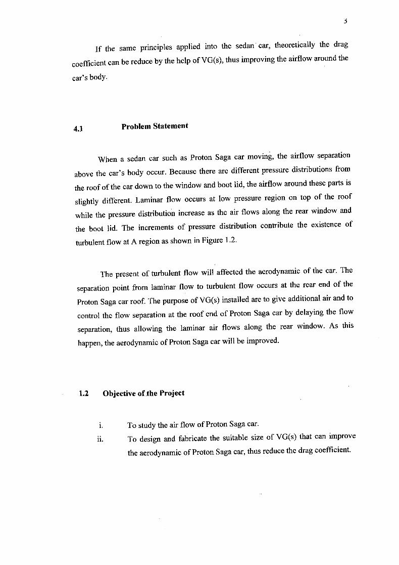
4.1 Problem Statement
When a sedan car such as Proton Saga car moving, the airflow separation
above the car's body occur. Because there are different pressure distributions from
the roof of the car down to the window and boot lid, the airflow around these parts is
slightly different. Laminar flow occurs at low pressure region on top of the roof
while the pressure distribution increase as the air flows along the rear window and
the boot lid. The increments of pressure distribution contribute the existence of
turbulent flow at A region as shown in Figure 1.2.
The present of turbulent flow will affected the aerodynamic of the car. The
separation point from laminar flow to turbulent flow occurs at the rear end of the
Proton Saga car roof. The purpose of VG(s) installed are to give additional air and to
control the flow separation at the roof end of Proton Saga car by delaying the flow
separation, thus allowing the laminar air flows along the rear window. As this
happen, the aerodynamic of Proton Saga car will be improved.
1.2 Objective of the Project
i. To study the air flow of Proton Saga car.
ii. To design and fabricate the suitable size of VG(s) that can improve
the aerodynamic of Proton Saga car, thus reduce the drag coefficient.
4
1.3 Scope of the Project
i. Observe and analyze airflow through Proton Saga car body using
wool tufts method.
ii. Fabricate suitable VG(s) using aluminum sheets.
iii. Literature study.

1.4 Flowchart
START
I DEFINE OBJECTIVES AND SCOPE
I LITERATURE STUDY
I RESEARCH METHODOLOGY
OBSERVE AND ANALYZE THE AIRFLOW WITHOUT VG
DESIGN THE VORTEX GENERATOR VG(s)
OBSERVE AND ANALYZE THE
NO I I AIRFLOW WITH VG(s)
AIRFLOW IMPROVE>
YES
RESULT AND DISCUSSION]
T CONCLUSION ]E: FYP FINAL PRESENTATION
4,
FYP FINAL REPORT SUBMISSION
Figure 1.3 Flowchart of the study

LSJ
1.5 Thesis Disposition
Chapter 1 is more towards the introduction of the project. The objectives of
the project, the scope and limitation and the problem statement on why this project is
necessary to be done discussed in this chapter. Chapter 1 also is an overview about
the project in more general view.
Chapter 2 is the Literature Review; discuss about the literature that referring
to the project. The content in this chapter is narrowed from the general description
about aerodynamics to the consequences of VG(s) usage on a car. Also include in
this chapter are the previous studies on VG(s) usage to improve the aerodynamics of
the car with different procedure.
The methodology of the study will be discuss in Chapter 3; Research
Methodology. The procedure for analysis, design and fabrication process will be
discussed in detail and systematic way. The material selection and procedure to be
done for goal achieve will be discuss later on.
Result and Discussion is the title for Chapter 4. All the result data, graphs,
photographic and calculation will be show and discuss in this chapter. the whole
conclusion whether the objective is achieve or not will be stated in Chapter 5 after
concerning all the result and analysis.

CHAPTER 2
LITERATURE REVIEW
5.0 Introduction
The purpose of this chapter is to explain about the principles of aerodynamics
especially on road vehicle which can be understood through fluids dynamics studies.
Chapter Two also discussed about the previous researches on VG(s). In addition, in
order to design the VG(s), the way of the flow through the vehicle must be observed.
This flow can be observed via aero test and using simulation which is will be
explained details in this chapter. From the previous research, the VG(s) was design to
suite a sedan car. A part from that, we can apply the mechanism of VG(s) to
Malaysian sedan car. This mechanism will be discussed details in Chapter Two.
Figure 2.1 shows the overview diagram for Chapter Two.

Aerodynamics of Road Vehicle
Automotive Aerodynamics
Flow separation
Laminar and Turbulence flow
Pressure Distribution on the car surface
Drag Coefficient
Airflow Measurement Techniques
Vortex Generator
Previous Studies of VG(s)
Consequences of VG(s)
Figure 2.1 Overview diagram for Literature Review

2.1 Aerodynamics
2.1.1 Definition
Aerodynamics is a branch of fluids mechanics which study about the forces
generated on a body in a flow 3]. The aerodynamics usually involves calculation in
the properties of the flow such as pressure, velocity, temperature, density as a
function of space and time. In order to calculate or approximate the forces and
moments acting on the bodies in the flow, we must understand the pattern of the
flows.
2.1.4 Classes of Aerodynamics Problems
Aerodynamic problem can occurred in many classes. The studies of flow
around solid objects of various shapes called the External Aerodynamics such as
evaluating the lift and drag on an airplane and the shock waves that form in front of
the nose of a rocket. The Internal Aerodynamic then studies about the flow through
passages in solid objects such as study of the airflow through a jet engine or through
an air conditioning pipe.
The second classification of aerodynamic is the ratio of the characteristic
flow speed to the speed of sound. A problem is called subsonic if all the speeds in the
problem are less than the speed of sound, transonic if speeds both below and above
the speed of sound are present, supersonic when the characteristic flow speed is
greater than the speed of sound, and hypersonic when the flow speed is much greater
than the speed of sound.
The third classification is concerned about the influence of viscosity. Some
problem involve only negligible viscous effects mean that the viscous can be

lv
considered not exist. This problem called inviscid flows meanwhile the flows which
viscosity cannot be neglected called viscous flows
2.1.5 Automotive Aerodynamics
Automotive aerodynamics is the study of the aerodynamics of road vehicles
[4]. This study involves reducing drag, reducing wind noise and preventing undesired
lift forces at high speed. It is also important to produce required downwards
aerodynamics force to improve traction and cornering abilities in some class of
racing car.
To have a small surface, the aerodynamic automotive will integrate the wheel
and lights. To be streamlined, it does not have shape edge crossing the wind stream
and feature a sort tail called fastback. The aerodynamic design will have a flat and
smooth to produce desirable downwards forces. The air rams into the engine bay for
used of cooling, combustion, passengers, reaccelerated by a nozzle and then ejected
under the floor.
Automotive aerodynamic is much different from the aircraft aerodynamic
such as road vehicle shapes is bluff, vehicle operates very close to the ground,
operating speed lower, the ground vehicle has fewer degrees of freedom and its
motion is less affected by aerodynamic forces.
Total Aerodynamic drag = Cd multiplied by the frontal area. The width and
height of curvy cars lead to gross overestimations of frontal area [4].

I
2.2 Flows Separation Through a Road Vehicle
2.2.1 Introduction
In determining and observing the aerodynamic of road vehicles it is important
to know the airflow through the vehicle's body. Basically, airflow around car's body
can be divided into two simple type which are laminar and turbulent flows. Both
layers can be describing in the boundary layer development on car's surface
2.2.2 Boundary Layer Development
In physics and fluid mechanics, the boundary layer is that layer of fluid in the
immediate vicinity of a bounding surface [5]. For flow over any surface, there will
always exist a velocity boundary layer and hence surface friction [6]. On a body of a
car, this surface friction could create drag force that could effect the aerodynamic of
the car. To introduce the concept of boundary layer, consider a flow through a plate
in Figure 2.2.
U. _ Free stream
U00
Velocity Y T ! boundary
I Ia er
bf
pp.x
Figure 2.2 Flow through a plate [1]

Y, v• A
—x, u Turbulent region
Buffer layer Laminar sublayer
12
Boundary layer velocity occurs when a consequence of viscous effects
associated with relative motion between a fluid and a surface. A region of the flow
characterized by shear stresses, t and velocity, u gradients. A region between the
surface and the free stream whose thickness increases in the flow direction. The
surface shear stress, 'rs provides the surface drag force, FD. The surface friction is
strongly depending on the flows condition weather laminar or turbulent flows. On
car's surface, the boundary layer becomes thicker towards the rear of the car. The
thicker the boundary layer, the more easily airflow will separate from the body,
leading to turbulent flow [6].
2.2.5 Laminar & Turbulent Flows
Figure 2.3 shows the laminar and turbulent flows of velocity boundary layer
development on a flat plate.
Streamline
xc
wl-4-1
- Laminar - i• Turbulent Transition
Figure 2.3 Velocity boundary layer development on a flat plate [1]
The laminar flow section preceding the turbulent flow section. Laminar flow
occurs where viscous forces are dominant and characterized by smooth, constant

13
fluid motion. Turbulent flow dominated by inertial forces, producing random eddies,
vortices and other flow fluctuations [6].
2.2.6 Flows Around Car's Body
Figure 2.4 shows the patterns of air flows through a Porsche body on a
common road. Note that the blue arrows represent laminar flow while the red arrows
represent turbulent flow.
Figure 2.4 Patterns of air flows through a Porsche body [7]
The patterns of airflow can be observed by sticking tuft-wool around the car
body and drove the car. Figure 2.5 shows how the tuft-wool sticked to the car body
to observe the airflow patterns.