English Keypad Assembly Installation WARNING — Shock ... · Button kit and faceplate materials...
6
Lutron Electronics Co., Inc. 7200 Suter Road, Coopersburg, PA 18036-1299 Installation 1. ! WARNING — Shock Hazard. May result in serious injury or death. Turn off power at the circuit breaker before installing the unit. Use these instructions to install the model numbers listed above. Important Notes Install in accordance with all national and local electrical codes. Lutron recommends that wallstations be installed by a qualified electrician. Do not connect high-voltage power to low-voltage terminals. Improper wiring can result in personal injury or damage to the control or to other equipment. Environment: Ambient operating temperature: 32 °F to 104 °F (0 °C to 40 °C), 0 to 90% humidity, non-condensing. Indoor use only. Cleaning: To clean, wipe with a clean damp cloth. DO NOT use any chemical cleaning solutions. Wallboxes: U.S. style wallbox: 3.7 in (95 mm) H × 1.8 in (46 mm) W × 2.8 in (70 mm) D Keypad Wiring • The total length of wire on a wired QS link is not to exceed 2000 ft (610 m). • Wiring may be in a daisy-chain, star, or T-tap configuration. System Programming: Programming and activation (addressing) must be accomplished through the system software. Engraving: Refer to the system software for button engraving instructions. Dynamic Backlighting Management (DBM): Unit is equipped with a light sensor and light pipe at the bottom of the keypad to aid in automatic adjustment of LED backlighting. DO NOT paint or obstruct sensor in any way. Button kit and faceplate materials cannot be mixed. For example, metal buttons must be installed with metal faceplates. Glass buttons must be installed with glass faceplates, etc. Button kit replacement. When replacing button kits, only 3BRL and 4B configurations are interchangeable. All others must be kept the same. For example, 2B replaced with a 2B kit or a 3B replaced with a 3B kit. Troubleshooting Guide Symptom Possible Causes No communication with QS processor. • Miswire or loose connection at the wired QS link. • Keypad has not been programmed or has been programmed incorrectly. Backlit keypad text scrolls quickly from bottom to top. • No communication with QS processor. • Miswire or loose connection at the wired QS link. Keypad buttons do not work; backlit text does not become brighter when pressed. • Keypad is miswired. • Keypad is not powered. • Keypad has not been programmed or has been programmed incorrectly. Backlit text does not turn on. • Make sure DBM sensor on bottom of unit is not covered or painted over. • Miswire or loose connection at the keypad(s) or processor on the wired QS link. • Keypad has been programmed incorrectly. Keypad buttons do not function as intended. • Keypad has not been programmed or has been programmed incorrectly. Button text appears upside down. • The button kit is installed upside down. Remove the bulk unit and rotate the button kit. )Lutron, Lutron, HomeWorks and Quantum are registered trademarks and Palladiom and myRoom are trademarks of Lutron Electronics Co., Inc. NEC is a registered trademark of the National Fire Protection Association, Quincy, Massachusetts. ©2015 Lutron Electronics Co., Inc. Installation Instructions Please Read Before Installing PalladiomTM QS Keypads 24–36 V- 30 mA Typical Power Consumption: 0.72 W IEC PELV / SELV / NEC® Class 2 Link Wiring IEC PELV / SELV / NEC® Class 2 Drain / Shield Data Link, One Shielded, Twisted Pair 22 AWG to 18 AWG (0.25 mm 2 to 1.0 mm 2 ) Technical Assistance: U.S.A. / Canada: 1.800.523.9466 | Europe: +44.(0)20.7680.4481 Mexico: +1.888.235.2910 | Brazil: +55 (11) 3257-6745 Other Countries: +1.610.282.3800 www.lutron.com | forums.lutron.com Wallbox HomeWorks® QS myRoomTM Quantum® HQWT-U-P2W MWP-U-2W QWP-U-2W HQWT-U-P3W MWP-U-3W QWP-U-3W HQWT-U-P4W MWP-U-4W QWP-U-4W HQWT-U-PRW MWP-U-RW QWP-U-RW Faceplates LWT-U-P; LWT-U-PP; LWT-U-PPP; LWT-U-PPPP d. Plug the keypad link terminal block back into the keypad. Returning Keypads to Factory Settings Returning a keypad to its Factory Settings will remove the keypad from the system and erase all programming. 1. Triple tap any button on the keypad (except raise / lower). DO NOT release after third tap. 2. Keep the button pressed on the third tap until all the LEDs start to flash slowly (approximately 3 seconds). 3. Immediately release the button and triple tap the button again. The LEDs on the keypad will flash quickly. The keypad has now been returned to Factory Settings. Warranty: For HomeWorks® QS: http://www.lutron.com/TechnicalDocumentLibrary/HomeWorks_Warranty.pdf For myRoomTM and Quantum®: http://www.lutron.com/en-US/ResourceLibrary/warranty/Lim_Warranty_starting_Oct2011.pdf * DO NOT paint or obstruct sensor in any way. COM V+ MUX MUX UX 22 AWG to 18 AWG (0.25 mm 2 to 1.0 mm 2 ) X 22 AWG to 18 AWG (0.25 mm 2 to 1.0 mm 2 ) Less than 500 ft (153 m) 500 ft to 2000 ft (153 m to 610 m) 12 AWG (2.5 mm 2 ) 12 AWG (2.5 mm 2 ) 3. Push all wires back into the wallbox. Do not pinch the wires. 4. Snap the keypad assembly onto the faceplate adapter. 5. Turn on the power. 2. Connect to wired QS link. a. Strip insulation 3/8 in (10 mm). b. Unplug keypad terminal block from the back of the keypad. c. Connect wiring to the terminal block as shown. Keypad Assembly Adapter Single Gang Supplied Screws (2) Keypad Assembly Note: When installing a new architectural receptacle in place of a keypad, the two sets of two Phillips head screws and two clear DBM light pipes must be removed from the top and bottom of the adapter so that the receptacle can be installed. Bulk Unit Button Kit Faceplate Base Unit DBM Light Pipe * Screws Front Back Wallbox Keypad Assembly Adapter Supplied Screws (4) Two Gang DBM Sensor Keypad Terminal Block Screws (4) (DO NOT overtighten) P/N 041496 Rev. D 10/2015 English
-
Upload
vuongxuyen -
Category
Documents
-
view
226 -
download
2
Transcript of English Keypad Assembly Installation WARNING — Shock ... · Button kit and faceplate materials...

Lutron Electronics Co., Inc.
7200 Suter Road, Coopersburg, PA 18036-1299
Installation
1. ! WARNING — Shock Hazard. May result in serious injury
or death. Turn off power at the circuit breaker before installing
the unit.
Use these instructions to install the model numbers listed above.
Important Notes
Install in accordance with all national and local electrical codes.
Lutron recommends that wallstations be installed by a qualified electrician.
Do not connect high-voltage power to low-voltage terminals. Improper wiring can result in personal injury or damage to the control or to other equipment.
Environment: Ambient operating temperature: 32 °F to 104 °F (0 °C to 40 °C), 0 to 90% humidity, non-condensing. Indoor use only.
Cleaning: To clean, wipe with a clean damp cloth. DO NOT use any chemical cleaning solutions.
Wallboxes: U.S. style wallbox: 3.7 in (95 mm) H × 1.8 in (46 mm) W × 2.8 in (70 mm) D
Keypad Wiring• The total length of wire on a wired QS link is not to exceed 2000 ft (610 m).
• Wiring may be in a daisy-chain, star, or T-tap configuration.
System Programming: Programming and activation (addressing) must be accomplished through the system software.
Engraving: Refer to the system software for button engraving instructions.
Dynamic Backlighting Management (DBM): Unit is equipped with a light sensor and light pipe at the bottom of the keypad to aid in automatic adjustment of LED backlighting. DO NOT paint or obstruct sensor in any way.
Button kit and faceplate materials cannot be mixed. For example, metal buttons must be installed with metal faceplates. Glass buttons must be installed with glass faceplates, etc.
Button kit replacement. When replacing button kits, only 3BRL and 4B configurations are interchangeable. All others must be kept the same. For example, 2B replaced with a 2B kit or a 3B replaced with a 3B kit.
Troubleshooting Guide Symptom Possible Causes
No communication with
QS processor.
• Miswire or loose connection at the wired
QS link.
• Keypad has not been programmed or has been
programmed incorrectly.
Backlit keypad text
scrolls quickly from
bottom to top.
• No communication with QS processor.
• Miswire or loose connection at the wired QS
link.
Keypad buttons do not
work; backlit text does
not become brighter
when pressed.
• Keypad is miswired.
• Keypad is not powered.
• Keypad has not been programmed or has
been programmed incorrectly.
Backlit text does not
turn on.
• Make sure DBM sensor on bottom of unit is not
covered or painted over.
• Miswire or loose connection at the keypad(s) or
processor on the wired QS link.
• Keypad has been programmed incorrectly.
Keypad buttons do not
function as intended.
• Keypad has not been programmed or has been
programmed incorrectly.
Button text appears
upside down.
• The button kit is installed upside down.
Remove the bulk unit and rotate the button kit.
)Lutron, Lutron, HomeWorks and Quantum are registered trademarks and Palladiom and myRoom are trademarks of Lutron Electronics Co., Inc.
NEC is a registered trademark of the National Fire Protection Association, Quincy, Massachusetts.
©2015 Lutron Electronics Co., Inc.
Installation InstructionsPlease Read Before Installing
PalladiomTM QS Keypads24–36 V- 30 mA
Typical Power Consumption: 0.72 W
IEC PELV / SELV / NEC® Class 2
Link WiringIEC PELV / SELV / NEC® Class 2
Drain / Shield
Data Link, One Shielded,
Twisted Pair 22 AWG to 18 AWG
(0.25 mm2 to 1.0 mm2)
Technical Assistance:
U.S.A. / Canada: 1.800.523.9466 | Europe: +44.(0)20.7680.4481
Mexico: +1.888.235.2910 | Brazil: +55 (11) 3257-6745
Other Countries: +1.610.282.3800 www.lutron.com | forums.lutron.com
Wallbox
HomeWorks® QS myRoomTM Quantum®
HQWT-U-P2W MWP-U-2W QWP-U-2W
HQWT-U-P3W MWP-U-3W QWP-U-3W
HQWT-U-P4W MWP-U-4W QWP-U-4W
HQWT-U-PRW MWP-U-RW QWP-U-RW
Faceplates
LWT-U-P; LWT-U-PP; LWT-U-PPP; LWT-U-PPPP
d. Plug the keypad link terminal block back into the keypad.
Returning Keypads to Factory Settings
Returning a keypad to its Factory Settings will remove the keypad from
the system and erase all programming.
1. Triple tap any button on the keypad (except raise / lower). DO NOT
release after third tap.
2. Keep the button pressed on the third tap until all the LEDs start to flash
slowly (approximately 3 seconds).
3. Immediately release the button and triple tap the button again. The
LEDs on the keypad will flash quickly.
The keypad has now been returned to Factory Settings.
Warranty:
For HomeWorks® QS:
http://www.lutron.com/TechnicalDocumentLibrary/HomeWorks_Warranty.pdf
For myRoomTM and Quantum®:
http://www.lutron.com/en-US/ResourceLibrary/warranty/Lim_Warranty_starting_Oct2011.pdf
* DO NOT paint or obstruct sensor in any way.
COM
V+
MUX
MUX
UX
22 AWG to 18 AWG
(0.25 mm2 to 1.0 mm2)
X22 AWG to 18 AWG
(0.25 mm2 to 1.0 mm2)
Less than 500 ft (153 m)
500 ft to 2000 ft (153 m to 610 m)
12 AWG
(2.5 mm2)
12 AWG
(2.5 mm2)
3. Push all wires back into the wallbox. Do not pinch the wires.
4. Snap the keypad assembly onto the faceplate adapter.
5. Turn on the power.
2. Connect to wired QS link.
a. Strip insulation 3/8 in (10 mm).
b. Unplug keypad terminal block from the back of the keypad.
c. Connect wiring to the terminal block as shown.
Keypad Assembly
Adapter
Single Gang
Supplied Screws (2)
Keypad Assembly
Note: When installing a new architectural receptacle in place of a keypad,
the two sets of two Phillips head screws and two clear DBM light pipes
must be removed from the top and bottom of the adapter so that the
receptacle can be installed.
Bulk Unit
Button Kit
Faceplate
Base Unit
DBM Light Pipe *
Screws
Front Back
Wallbox
Keypad Assembly
Adapter
Supplied Screws (4)
Two Gang
DBM Sensor
Keypad
Terminal
Block
Screws (4)
(DO NOT
overtighten)P/N 041496 Rev. D
10/2015
English
Lutron Electronics Co., Inc.
7200 Suter Road, Coopersburg, PA 18036-1299
N° de pièce 041496 Rév. D
10/2015
Installation
1. ! AVERTISSEMENT — Risque d’électrocution. Peut causer
des blessures graves ou la mort. Coupez l'alimentation au
niveau du disjoncteur avant d'installer l'unité.
Utilisez ces instructions pour installer les numéros de modèles énumérés ci-dessus.
Remarques importantes
Effectuez l'installation en conformité avec les codes électriques en vigueur.
Lutron recommande de faire installer les interfaces murales par un électricien qualifié.
Ne connectez pas l'alimentation haute-tension aux bornes basse-tension. Un mauvais câblage peut causer des blessures ou endommager le clavier ou un autre équipement.
Environnement : Température ambiante de fonctionnement : 0 °C à 40 °C (32 °F à 104 °F), 0 à 90 % d'humidité, sans condensation. Utilisation à l'intérieur seulement.
Nettoyage : Pour nettoyer, essuyez avec un torchon propre et humide. N'UTILISEZ aucun produit chimique de nettoyage.
Boîtiers d'encastrement : Boîtier d'encastrement de type américain : 95 mm (3,7 po) H × 46 mm (1,8 po) l × 70 mm (2,8 po) P
Câblage du clavier• La longueur totale de câble sur une liaison câblée QS ne doit pas
dépasser 610 m (2 000 pi).
• Le câblage peut être en série, en parallèle ou en étoile.
Programmation du système : La programmation et l'activation (adressage) doivent être effectuées à l'aide du logiciel du système.
Gravure : Consultez le logiciel du système pour les instructions de gravure de boutons.
Gestion du rétroéclairage dynamique (Dynamic Backlighting Management / DBM) : L’unité est équipée d’un détecteur de lumière et d’un conduit de lumière en bas du clavier pour permettre le réglage automatique du rétroéclairage des LED. NE PAS peindre ou bloquer le détecteur de quelque façon.
Le kit de boutons et les matériaux de la plaque frontale ne peuvent pas être mélangés. Par exemple, des boutons métalliques doivent être installés sur des plaques frontales métalliques. Des boutons en verre doivent être installés sur des plaques frontales en verre, etc.
Remplacement du kit de boutons. Lors du remplacement des kits de boutons, seules les configurations 3BRL et 4B sont interchangeables. Toutes les autres doivent rester identiques. Par exemple, un kit 2B est remplacé par un kit 2B ou un kit 3B est remplacé par un kit 3B.
Guide de dépannage Symptôme Causes possibles
Aucune communication
avec le processeur QS.
• Mauvais raccord ou faux contact sur la liaison
câblée QS.
• Le clavier n'a pas été programmé ou a été mal
programmé.
Le texte rétroéclairé du
clavier défile rapidement
de bas en haut.
• Aucune communication avec le processeur QS.
• Mauvais raccord ou faux contact sur la liaison
câblée QS.
Les boutons du clavier
ne fonctionnent pas ;
le texte rétroéclairé ne
s'illumine pas lorsqu’on
appuie dessus.
• Le clavier est mal câblé.
• Le clavier n'est pas alimenté.
• Le clavier n'a pas été programmé ou a été mal
programmé.
Le texte rétroéclairé ne
s’allume pas.
• Vérifiez que le détecteur de DBM en bas de
l’unité n’est pas recouvert ou peint.
• Mauvais raccord ou faux contact au niveau du
(des) clavier(s) ou du processeur sur la liaison
câblée QS.
• Le clavier a été mal programmé.
Les boutons du clavier ne
fonctionnent pas comme
prévu.
• Le clavier n'a pas été programmé ou a été mal
programmé.
Le texte du bouton
apparaît à l’envers.
• Le kit de boutons est installé à l’envers. Retirez
l’unité en vrac et retournez le kit de boutons.
)Lutron, Lutron, HomeWorks et Quantum sont des marques déposées et Palladiom et myRoom sont des marques commerciales de Lutron Electronics Co., Inc.
NEC est une marque déposée de la National Fire Protection Association, Quincy, Massachusetts.
©2015 Lutron Electronics Co., Inc.
Instructions d'installationVeuillez lire avant l'installation
Claviers PalladiomTM QS24–36 V- 30 mA
Consommation électrique typique : 0,72 W
IEC PELV / SELV / NEC® de classe 2
Câblage de la liaisonIEC PELV / SELV / NEC® de classe 2
Blindage
Liaison des données, une paire
de câbles torsadés et blindés
de 0,25 mm2 à 1,0 mm2
(22 AWG à 18 AWG)
Assistance technique :
États-Unis / Canada : 1.800.523.9466 | Europe : +44.(0)20.7680.4481
Mexique : +1.888.235.2910 | Brésil : +55 (11) 3257-6745
Autres pays : +1.610.282.3800 www.lutron.com | forums.lutron.com
Boîtier mural
HomeWorks® QS myRoomTM Quantum®
HQWT-U-P2W MWP-U-2W QWP-U-2W
HQWT-U-P3W MWP-U-3W QWP-U-3W
HQWT-U-P4W MWP-U-4W QWP-U-4W
HQWT-U-PRW MWP-U-RW QWP-U-RW
Plaques frontales
LWT-U-P ; LWT-U-PP ; LWT-U-PPP ; LWT-U-PPPP
d. Rebranchez le bornier de liaison du clavier sur le clavier.
Restauration des paramètres d'usine des claviers
Restaurer les paramètres d'usine d'un clavier supprimera le clavier du
système et effacera toute programmation.
1. Appuyez trois fois sur n'importe quel bouton du clavier (sauf Monter/
Baisser). NE RELÂCHEZ PAS le bouton la troisième fois.
2. Gardez le bouton appuyé la troisième fois jusqu'à ce que les LED
commencent à clignoter lentement (pendant environ 3 secondes).
3. Relâchez immédiatement le bouton et appuyez trois fois sur le bouton
à nouveau. Les LED du clavier clignoteront rapidement.
Le clavier est de nouveau réglé avec les paramètres d'usine.
Garantie :
Pour HomeWorks® QS :
http://www.lutron.com/TechnicalDocumentLibrary/HomeWorks_Warranty.pdf
Pour myRoomTM et Quantum® :
http://www.lutron.com/en-US/ResourceLibrary/warranty/Lim_Warranty_starting_Oct2011.pdf
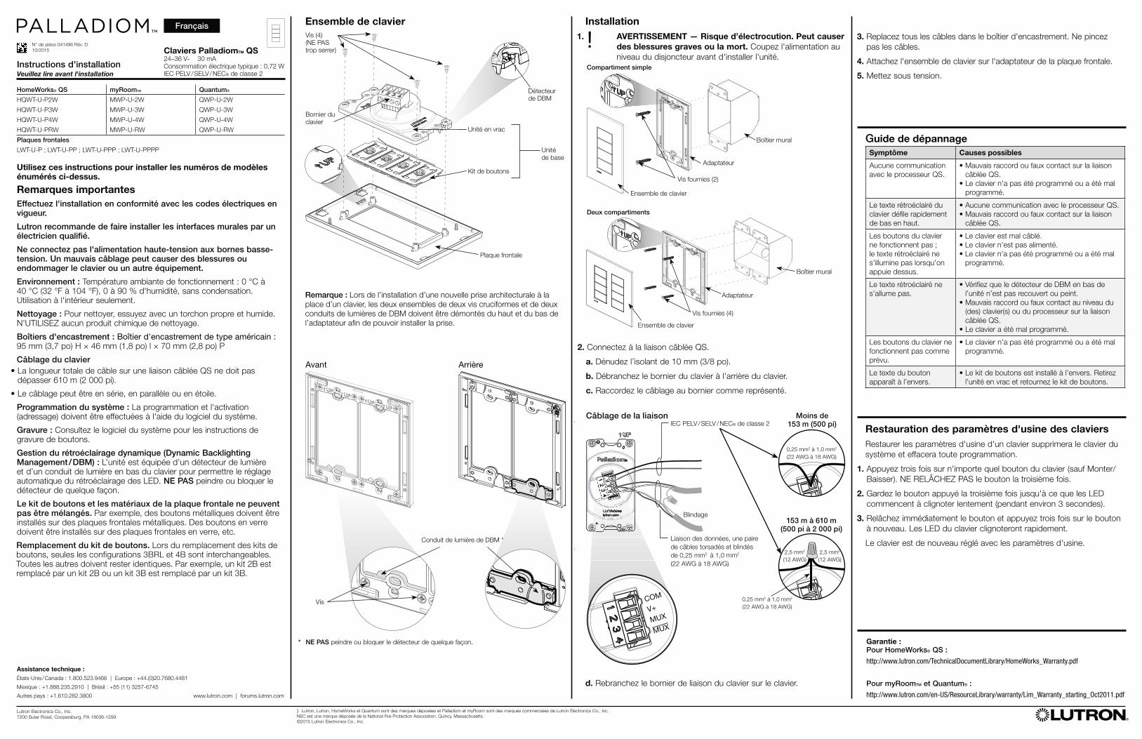
* NE PAS peindre ou bloquer le détecteur de quelque façon.
COM
V+
MUX
MUX
UX
0,25 mm2 à 1,0 mm2
(22 AWG à 18 AWG)
X0,25 mm2 à 1,0 mm2
(22 AWG à 18 AWG)
Moins de 153 m (500 pi)
153 m à 610 m (500 pi à 2 000 pi)
2,5 mm2
(12 AWG)
2,5 mm2
(12 AWG)
3. Replacez tous les câbles dans le boîtier d'encastrement. Ne pincez
pas les câbles.
4. Attachez l'ensemble de clavier sur l'adaptateur de la plaque frontale.
5. Mettez sous tension.
2. Connectez à la liaison câblée QS.
a. Dénudez l’isolant de 10 mm (3/8 po).
b. Débranchez le bornier du clavier à l'arrière du clavier.
c. Raccordez le câblage au bornier comme représenté.
Ensemble de clavier
Adaptateur
Compartiment simple
Vis fournies (2)
Ensemble de clavier
Remarque : Lors de l’installation d’une nouvelle prise architecturale à la
place d’un clavier, les deux ensembles de deux vis cruciformes et de deux
conduits de lumières de DBM doivent être démontés du haut et du bas de
l’adaptateur afin de pouvoir installer la prise.
Unité en vrac
Kit de boutons
Plaque frontale
Unité
de base
Conduit de lumière de DBM *
Vis
Avant Arrière
Boîtier mural
Ensemble de clavier
Adaptateur
Vis fournies (4)
Deux compartiments
Détecteur
de DBM
Bornier du
clavier
Vis (4)
(NE PAS
trop serrer)
Français
Lutron Electronics Co., Inc.
7200 Suter Road, Coopersburg, PA 18036-1299
P/N 041496 Rev. D
10/2015
Instalación
1. ! ADVERTENCIA — Peligro de descarga eléctrica. Puede ocasionar lesiones graves o la muerte. Corte la alimentación eléctrica en el interruptor de circuitos antes de instalar la unidad.
Siga estas instrucciones para instalar los números de modelo listados anteriormente.
Notas importantes
Instale de acuerdo a todos los códigos eléctricos nacionales y locales.
Lutron recomienda que un electricista calificado instale las estaciones de control.
No conecte corriente de alto voltaje a terminales de bajo voltaje. El cableado incorrecto puede ocasionar lesiones personales o daños al control o a otros equipos.
Medio ambiente: Temperatura ambiente de funcionamiento: 0 °C a 40 °C (32 °F a 104 °F), 0 a 90% de humedad, sin condensación. Solamente para uso en interiores.
Limpieza: Para limpiar pase un paño limpio y húmedo. NO use ninguna solución química de limpieza.
Cajas de empotrar: Caja de empotrar estilo E.U.A.: 95 mm (3,7 pulg) de alto × 46 mm (1,8 pulg) de ancho × 70 mm (2,8 pulg) de profundidad.
Cableado del teclado• La longitud total de cable en un enlace QS cableado no debe exceder
610 m (2 000 pies).
• El cableado puede tener una configuración concatenada, en estrella, o con derivación en T.
Programación del sistema: La programación y la activación (direccionamiento) se debe hacer con el software del sistema.
Grabado: Consulte las instrucciones de grabado de botones en el software del sistema.
Gestión de retroiluminación dinámica (Dynamic Backlighting Management / DBM): La unidad está equipada con un sensor de luz y un conducto de luz en la parte inferior del teclado para facilitar el ajuste automático de la retroiluminación de diodos LED. NO pinte ni obstruya el sensor de ninguna forma.
No se deben mezclar juegos de botones con placas frontales de distintos materiales. Por ejemplo, los botones de metal se deben instalar en placas frontales de metal. Los botones de vidrio se deben instalar en placas frontales de vidrio, etc.
Reemplazo de juegos de botones. Al reemplazar juegos de botones, solo las configuraciones 3BRL y 4B son intercambiables. El resto se debe mantener igual al original. Por ejemplo, 2B se debe reemplazar con un juego 2B, y un juego 3B se debe reemplazar con un juego 3B.
Guía de resolución de problemas Síntoma Posibles causas
No hay comunicación
con el procesador QS.
• Cableado incorrecto o conexión suelta en el
enlace QS cableado.
• El teclado no ha sido programado o ha sido
programado de manera incorrecta.
El texto retroiluminado
del teclado circula
rápidamente de la parte
inferior a la superior.
• No hay comunicación con el procesador QS.
• Cableado incorrecto o conexión suelta en el
enlace QS cableado.
Los botones del teclado
no funcionan; no
aumenta la luminosidad
del texto retroiluminado
al oprimir.
• El teclado está cableado de forma incorrecta.
• El teclado no está conectado a la corriente
eléctrica.
• El teclado no ha sido programado o ha sido
programado de manera incorrecta.
El texto retroiluminado no
se enciende.
• Asegúrese de que el sensor DBM en la parte
inferior de la unidad no esté cubierto y de que
no se haya pintado sobre el mismo.
• Cableado incorrecto o conexión suelta en los
teclados o en el procesador en el enlace QS
cableado.
• El teclado ha sido programado de manera
incorrecta.
Los botones del teclado
no funcionan como
debieran.
• El teclado no ha sido programado o ha sido
programado de manera incorrecta.
El texto en el botón
aparece al revés.
• El juego de botones fue instalado al revés. Retire
la unidad principal y gire el juego de botones.
)Lutron, Lutron, HomeWorks y Quantum son marcas de fábrica registradas, y Palladiom y myRoom son marcas de fábrica de Lutron Electronics Co., Inc.
NEC es una marca de fábrica registrada de la National Fire Protection Association (Asociaión de Protección Antiincendios de Estados Unidos), Quincy, Massachusetts.
© 2015 Lutron Electronics Co., Inc.
Instrucciones de instalaciónFavor de leer antes de hacer la instalación
Teclados PalladiomTM QS24–36 V- 30 mA
Consumo típico de corriente
eléctrica: 0,72 W
IEC PELV / SELV / NEC® Clase 2
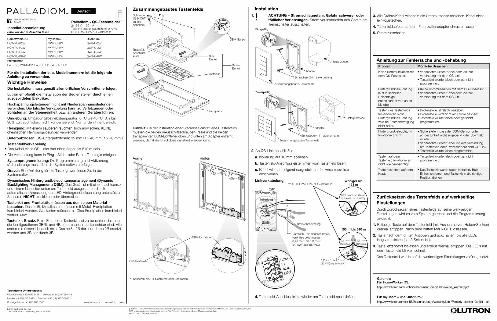
Cableado de enlaceIEC PELV / SELV / NEC® Clase 2
Drenado / Blindaje
Enlace de datos, un par trenzado
blindado de 0,25 mm2 a 1,0 mm2
(22 AWG a 18 AWG)
Asistencia técnica:
E.U.A. / Canadá: 1.800.523.9466 | Europa: +44.(0)20.7680.4481
México: +1.888.235.2910 | Brasil: +55 (11) 3257-6745
Otros países: +1.610.282.3800 www.lutron.com | forums.lutron.com
Caja de empotrar
HomeWorks® QS myRoomTM Quantum®
HQWT-U-P2W MWP-U-2W QWP-U-2W
HQWT-U-P3W MWP-U-3W QWP-U-3W
HQWT-U-P4W MWP-U-4W QWP-U-4W
HQWT-U-PRW MWP-U-RW QWP-U-RW
Placas frontales
LWT-U-P; LWT-U-PP; LWT-U-PPP; LWT-U-PPPP
d. Enchufe de nuevo el bloque de terminales de enlace del teclado
en el teclado.
Restablecimiento de teclados a la configuración
de fábrica
Al restablecer un teclado a la configuración de fábrica se elimina el
teclado del sistema y se borra toda la programación.
1. Dé tres golpecitos en cualquier botón del teclado (excepto
subir / bajar). NO deje de oprimir después del tercer golpecito.
2. Mantenga oprimido el botón en el tercer golpecito hasta que todos los
diodos LED comiencen a centellear lentamente (aproximadamente
3 segundos).
3. Suelte de inmediato el botón y una vez más dé tres golpecitos al
botón. Los diodos LED en el teclado deben comenzar a centellear
rápidamente.
El teclado queda así en la configuración de fábrica.
Garantía:
Para HomeWorks® QS:
http://www.lutron.com/TechnicalDocumentLibrary/HomeWorks_Warranty.pdf
Para myRoomTM y Quantum®:
http://www.lutron.com/en-US/ResourceLibrary/warranty/Lim_Warranty_starting_Oct2011.pdf
* NO pinte ni obstruya el sensor de ninguna forma.
COM
V+
MUX
MUX
UX
0,25 mm2 a 1,0 mm2
(22 AWG a 18 AWG)
X0,25 mm2 a 1,0 mm2
(22 AWG a 18 AWG)
Menos de 153 m (500 pies)
153 m a 610 m (500 pies a 2 000 pies)
2,5 mm2
(12 AWG)
2,5 mm2
(12 AWG)
3. Empuje todos los cables de nuevo dentro de la caja de empotrar.
Los cables no deben quedar pellizcados.
4. Oprima a presión el conjunto del teclado en el adaptador de la
placa frontal.
5. Vuelva a conectar la alimentación eléctrica.
2. Conecte a un enlace QS cableado.
a. Quite 10 mm (3/8 pulg) de aislante.
b. Desenchufe el bloque de terminales del teclado de la parte
posterior del teclado.
c. Conecte el cableado al bloque de terminales, como se indica.
Conjunto del teclado
Adaptador
Agrupamiento sencillo
Tornillos incluidos (2)
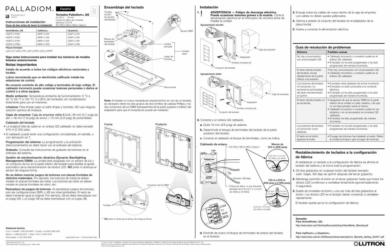
Ensamblaje del teclado
Nota: Al instalar un nuevo receptáculo arquitectónico en vez de un teclado,
es necesario retirar los dos grupos de dos tornillos de cabeza Phillips y los
dos conductos de luz DBM transparentes de la parte superior e inferior del
adaptador para que el receptáculo pueda ser instalado.
Unidad
principal
Juego de
botones
Placa frontal
Unidad
base
Conducto de luz DBM *
Tornillos
Frente Posterior
Caja de empotrar
Conjunto del teclado
Adaptador
Tornillos incluidos (4)
Agrupamiento doble
Sensor DBM
Bloque de
terminales
del teclado
Tornillos
(4) (NO
los apriete
demasiado)
Español
Lutron Electronics Co., Inc.
7200 Suter Road, Coopersburg, PA 18036-1299
Best.-Nr. 041496 Rev. D
10/2015
Installation
1. ! ACHTUNG – Stromschlaggefahr. Gefahr schwerer oder
tödlicher Verletzungen. Strom vor Installation des Geräts am
Trennschalter ausschalten.
Für die Installation der o. a. Modellnummern ist die folgende Anleitung zu verwenden.
Wichtige Hinweise
Die Installation muss gemäß allen örtlichen Vorschriften erfolgen.
Lutron empfiehlt die Installation der Bedienstellen durch einen ausgebildeten Elektriker.
Hochspannungsleitungen nicht mit Niederspannungsleitungen verbinden. Die falsche Verkabelung kann zu Verletzungen oder Schäden an der Steuereinheit bzw. an anderen Geräten führen.
Umgebung: Umgebungsbetriebstemperatur: 0 °C bis 40 °C, 0% bis 90% Luftfeuchtigkeit, nicht kondensierend. Nur für den Innenbereich.
Reinigung: Mit einem sauberen feuchten Tuch abwischen. KEINE chemischen Reinigungslösungen verwenden.
Unterputzdosen: US-Unterputzdosen: 95 mm H × 46 mm B × 70 mm T
Tastenfeldverkabelung• Das Kabel eines QS-Links darf nicht länger als 610 m sein.
• Die Verkabelung kann in Ring-, Stich- oder Baum-Topologie erfolgen.
Systemprogrammierung: Die Programmierung und Aktivierung (Adressierung) muss über die Systemsoftware erfolgen.
Gravur: Eine Anleitung für die Tastengravur finden Sie in der Systemsoftware.
Dynamisches Hintergrundbeleuchtungsmanagement (Dynamic Backlighting Management / DBM): Das Gerät ist mit einem Lichtsensor und einem Lichtleiter unten am Tastenfeld ausgestattet, die die automatische Anpassung der LED-Hintergrundbeleuchtung unterstützen. Sensoren NICHT blockieren oder übermalen.
Tastenkit und Frontplatte müssen aus demselben Material bestehen. Das heißt, Metalltasten müssen mit Metall-Frontplatten kombiniert werden. Glastasten müssen mit Glas-Frontplatten kombiniert werden usw.
Tastenkit-Ersatz. Beim Ersatz der Tastenkits ist zu beachten, dass nur die Konfigurationen 3BRL und 4B untereinander austauschbar sind. Alle anderen müssen identisch sein. Das heißt, 2B darf nur durch 2B ersetzt werden und 3B nur durch 3B.
Anleitung zur Fehlersuche und -behebung Problem Mögliche Ursachen
Keine Kommunikation mit
dem QS-Prozessor.
• Vertauschte Litzen/Kabel oder lockere
Verbindung mit dem QS-Link.
• Tastenfeld wurde falsch oder gar nicht
programmiert.
Hintergrundbeleuchtung
läuft in schneller
Reihenfolge
nacheinander von unten
bis oben.
• Keine Kommunikation mit dem QS-Prozessor.
• Vertauschte Litzen/Kabel oder lockere
Verbindung mit dem QS-Link.
Tasten des Tastenfelds
funktionieren nicht.
Hintergrundbeleuchtung
wird bei Tastenbetätigung
nicht heller.
• Bedienstelle ist falsch verkabelt.
• Bedienstelle wird nicht mit Strom gespeist.
• Tastenfeld wurde falsch oder gar nicht
programmiert.
Hintergrundbeleuchtung
funktioniert nicht.
• Sicherstellen, dass der DBM-Sensor unten
an der Einheit nicht zugedeckt oder übermalt
wurde.
• Vertauschte Litzen/Kabel, lockere Verbindung
am Tastenfeld oder Prozessor auf dem QS-Link.
• Tastenfeld wurde falsch programmiert.
Tasten auf dem
Tastenfeld funktionieren
nicht wie beabsichtigt.
• Tastenfeld wurde falsch oder gar nicht
programmiert.
Tastentext steht auf dem
Kopf.
• Das Tastenkit wurde falsch installiert. Bulk-
Einheit entfernen und Tastenkit in die richtige
Position drehen.
)Lutron, Lutron, HomeWorks und Quantum sind eingetragene Marken und Palladiom und myRoom sind Marken von Lutron Electronics Co., Inc.
NEC ist eine eingetragene Marke der National Fire Protection Association, Quincy, Massachusetts (USA).
©2015 Lutron Electronics Co., Inc.
InstallationsanleitungBitte vor der Installation lesen
PalladiomTM QS-Tastenfelder24–36 V- 30 mA
Typische Leistungsaufnahme: 0,72 W
IEC PELV / SELV / NEC® Klasse 2
LinkverkabelungIEC PELV / SELV / NEC® Klasse 2
Drain/Abschirmung
Datenlink – ein abgeschirmtes,
verdrilltes Leitungspaar
0,25 mm2 bis 1,0 mm2
(22 AWG bis 18 AWG)
Technische Unterstützung:
USA /Kanada: 1.800.523.9466 | Europa: +44.(0)20.7680.4481
Mexiko: +1.888.235.2910 | Brasilien: +55 (11) 3257-6745
Sonstige Länder: +1.610.282.3800 www.lutron.com | forums.lutron.com
Unterputzdose
HomeWorks® QS myRoomTM Quantum®
HQWT-U-P2W MWP-U-2W QWP-U-2W
HQWT-U-P3W MWP-U-3W QWP-U-3W
HQWT-U-P4W MWP-U-4W QWP-U-4W
HQWT-U-PRW MWP-U-RW QWP-U-RW
Frontplatten
LWT-U-P; LWT-U-PP; LWT-U-PPP; LWT-U-PPPP
d. Tastenfeld-Anschlussleiste wieder am Tastenfeld anschließen.
Zurücksetzen des Tastenfelds auf werkseitige
Einstellungen
Durch Zurücksetzen eines Tastenfelds auf seine werkseitigen
Einstellungen wird es vom System getrennt und die Programmierung
gelöscht.
1. Beliebige Taste auf dem Tastenfeld (mit Ausnahme von Heben/Senken)
dreimal antippen. Nach dem dritten Mal NICHT loslassen.
2. Taste nach dem dritten Antippen gedrückt halten, bis alle LEDs
langsam blinken (ca. 3 Sekunden).
3. Taste jetzt sofort loslassen und erneut dreimal antippen. Die LEDs auf
dem Tastenfeld blinken schnell.
Das Tastenfeld wurde auf die werkseitigen Einstellungen zurückgesetzt.
Garantie:
Für HomeWorks® QS:
http://www.lutron.com/TechnicalDocumentLibrary/HomeWorks_Warranty.pdf
Für myRoomTM und Quantum®:
http://www.lutron.com/en-US/ResourceLibrary/warranty/Lim_Warranty_starting_Oct2011.pdf
* Sensoren NICHT blockieren oder übermalen.
COM
V+
MUX
MUX
UX
0,25 mm2 bis 1,0 mm2
(22 AWG bis 18 AWG)
X0,25 mm2 bis 1,0 mm2
(22 AWG bis 18 AWG)
Weniger als 153 m
153 m bis 610 m
3. Alle Drähte/Kabel wieder in die Unterputzdose schieben. Kabel nicht
(ein-)quetschen.
4. Tastenfeldaufbau auf dem Frontplattenadapter einrasten lassen.
5. Strom einschalten.
2. An QS-Link anschließen.
a. Isolierung auf 10 mm abziehen.
b. Tastenfeld-Anschlussleiste hinten vom Tastenfeld lösen.
c. Kabel wie nachfolgend dargestellt an der Anschlussleiste
anschließen.
Zusammengebautes Tastenfelds
Adapter
Einspaltig
Schrauben (2) im Lieferumfang
Zusammengebautes Tastenfelds
Hinweis: Bei der Installation einer Steckdose anstatt eines Tastenfelds
müssen die beiden Kreuzschlitzschrauben-Paare und die beiden
transparenten DBM-Lichtleiter oben und unten am Adapter entfernt
werden, damit die Steckdose installiert werden kann.
Bulk-
Einheit
Tastenkit
Frontplatte
Basis-
Einheit
DBM-Lichtröhre *
Schrauben
Vorne Hinten
Unterputzdose
Zusammengebautes Tastenfelds
Adapter
Schrauben (4) im Lieferumfang
Zweispaltig
DBM-Sensor
Tastenfeld-
Anschluss-
leiste
Schrauben
(4) (NICHT
zu fest
anziehen)
Deutsch
2,5 mm2
(12 AWG)
2,5 mm2
(12 AWG)
Lutron Electronics Co., Inc.
7200 Suter Road, Coopersburg, PA 18036-1299
P/N 041496 Rev. D
10/2015
Instalação
1. ! ADVERTÊNCIA: risco de choque. Pode resultar em
ferimentos graves ou morte. Desligue o disjuntor antes de
instalar a unidade.
Utilize estas instruções para instalar os números de modelo listados acima.
Notas importantes
A instalação elétrica deve ser feita de acordo com as normas locais e nacionais.
A Lutron recomenda que os acessórios de parede sejam instalados por um eletricista qualificado.
Não se deve conectar energia de alta voltagem a terminais de baixa voltagem. O cabeamento inadequado pode resultar em ferimentos pessoais ou danos ao controle ou a outros equipamentos.
Ambiente: Temperatura operacional: 0 °C a 40 °C (32 °F a 104 °F), 0%-90% de umidade, sem condensação. Para uso somente em ambientes fechados.
Limpeza: Para limpar, use um pano limpo e úmido. NÃO use produtos químicos de limpeza.
Caixas de embutir: estilo americano: 95 mm (3,7 pol) A × 46 mm (1,8 pol) L × 70 mm (2,8 pol) P
Cabeamento do teclado• A extensão total do fio em um Link QS não pode ser superior a 610 m
(2 000 pés).
• O cabeamento do teclado pode ter configuração de ligação em série, estrela ou derivação em T.
Programação do sistema: a programação e a ativação (endereçamento) devem ser feitas pelo software do sistema.
Gravação: consulte o software do sistema para obter instruções de gravação.
Gerenciamento dinâmico de iluminação traseira (Dynamic Backlighting Management / DBM): a unidade é equipada com um sensor de luz e uma tubulação de luz na parte inferior do teclado, para auxiliar o ajuste automático da iluminação traseira de LED. NÃO pinte nem obstrua o sensor.
Os materiais do kit de botões e do espelho não podem ser misturados. Por exemplo, os botões de metal devem ser instalados com os espelhos de metal. Os botões de vidro devem ser instalados com os espelhos de vidro, etc.
Substituição do kit de botões. Para substituir kits de botões, somente as configurações 3BRL e 4B são intercambiáveis. As demais deverão ser mantidas da mesma forma. Por exemplo, a configuração 2B pode ser substituída pelo kit 2B, ou a 3B substituída pelo kit 3B.
Guia de solução de problemas Problema Possíveis causas
Não há comunicação
com o processador QS.
• Conexão incorreta ou fio solto no link QS.
• O teclado não foi programado ou foi
programado incorretamente.
O texto do teclado com
iluminação traseira rola
rapidamente de baixo
para cima.
• Não há comunicação com o processador QS.
• Conexão incorreta ou fio solto no link QS.
Os botões do teclado
não funcionam; o texto
com iluminação traseira
não fica iluminado
quando as teclas são
pressionadas.
• O teclado foi conectado incorretamente.
• Falta alimentação ao teclado.
• O teclado não foi programado ou foi
programado incorretamente.
A iluminação traseira não
funciona.
• O sensor DBM na parte inferior da unidade não
pode ser coberto nem pintado.
• Conexão incorreta ou solta no(s) teclado(s) ou
na fiação da processadora do link QS.
• O teclado foi programado incorretamente.
Os botões do teclado
não funcionam como
deveriam.
• O teclado não foi programado ou foi
programado incorretamente.
O texto dos botões
aparece de cabeça para
baixo.
• O kit de botões foi instalado de cabeça para
baixo. Retire a unidade principal e gire o kit
de botões.
)Lutron, Lutron, HomeWorks e Quantum são marcas comerciais registradas. Palladiom e myRoom são marcas comerciais da Lutron Electronics Co., Inc.
NEC é marca comercial registrada da National Fire Protection Association, de Quincy, Massachusetts, EUA.
©2015 Lutron Electronics Co., Inc.
Instruções de instalaçãoLeia antes de instalar
Teclados PalladiomTM QS24–36 V- 30 mA
Consumo médio: 0,72 W
Classe 2 IEC PELV / SELV / NEC®
Cabeamento do linkClasse 2 IEC PELV/SELV/NEC®
Cabo de drenagem
Link de dados, um par blindado
trançado de 0,25 mm2 a 1,0 mm2
(22 AWG a 18 AWG)
Assistência técnica:
EUA /Canadá: 1.800.523.9466 | Europa: +44.(0)20.7680.4481
México: +1.888.235.2910 | Brasil: +55 (11) 3257-6745
Outros países: +1.610.282.3800 www.lutron.com | forums.lutron.com
Caixa de embutir
HomeWorks® QS myRoomTM Quantum®
HQWT-U-P2W MWP-U-2W QWP-U-2W
HQWT-U-P3W MWP-U-3W QWP-U-3W
HQWT-U-P4W MWP-U-4W QWP-U-4W
HQWT-U-PRW MWP-U-RW QWP-U-RW
Espelhos
LWT-U-P; LWT-U-PP; LWT-U-PPP; LWT-U-PPPP
d. Reconecte o bloco terminal do link no teclado.
Reverter o teclado à configuração de fábrica
Reverter o teclado à configuração de fábrica o retirará do sistema e
apagará toda a programação.
1. Pressione levemente três vezes qualquer botão do teclado (exceto
sobe/desce). NÃO solte após a terceira vez.
2. Mantenha o botão pressionado na terceira vez até que todos os LEDs
comecem a piscar lentamente (aproximadamente 3 segundos).
3. Solte imediatamente o botão e pressione-o três vezes novamente. Os
LEDs do teclado piscarão rapidamente.
O teclado agora está com as configurações de fábrica.
Garantia:
Do HomeWorks® QS:
http://www.lutron.com/TechnicalDocumentLibrary/HomeWorks_Warranty.pdf
Do myRoomTM e do Quantum®:
http://www.lutron.com/en-US/ResourceLibrary/warranty/Lim_Warranty_starting_Oct2011.pdf
* NÃO pinte nem obstrua o sensor.
COM
V+
MUX
MUX
UX
0,25 mm2 a 1,0 mm2
(22 AWG a 18 AWG)
X0,25 mm2 a 1,0 mm2
(22 AWG a 18 AWG)
Menor do que 153 m (500 pés)
153 m a 610 m (500 pés a 2 000 pés)
2,5 mm2
(12 AWG)
2,5 mm2
(12 AWG)
3. Coloque todos os fios dentro da caixa de embutir. Não esprema
os cabos.
4. Encaixe o teclado no adaptador do espelho.
5. Restaure a energia.
2. Conectar ao Link QS.
a. Retire 10 mm (3/8 pol) do isolamento.
b. Desconecte o bloco terminal da traseira do teclado.
c. Conecte o bloco terminal conforme mostrado na figura.
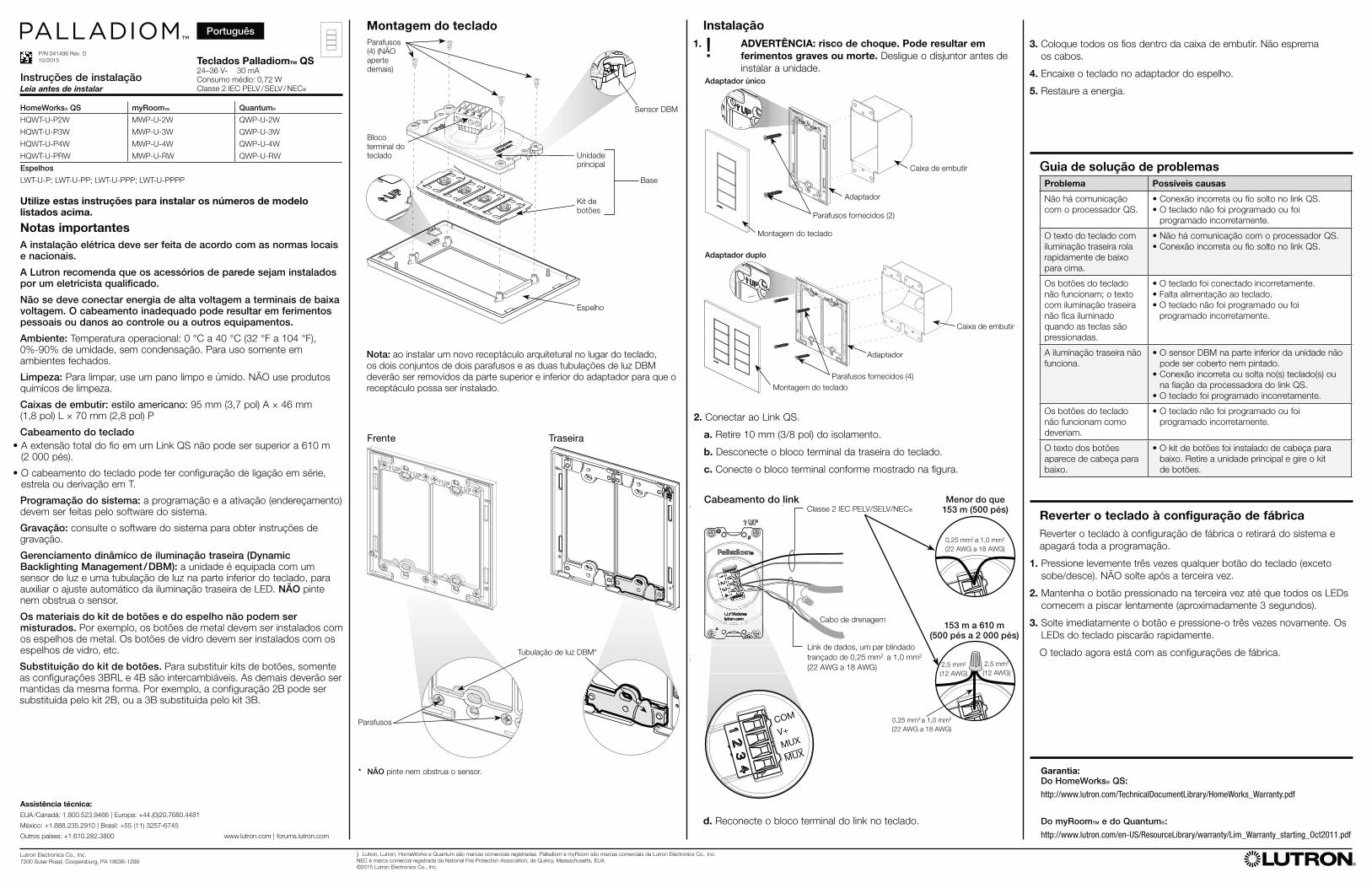
Montagem do teclado
Adaptador
Adaptador único
Parafusos fornecidos (2)
Montagem do teclado
Nota: ao instalar um novo receptáculo arquitetural no lugar do teclado,
os dois conjuntos de dois parafusos e as duas tubulações de luz DBM
deverão ser removidos da parte superior e inferior do adaptador para que o
receptáculo possa ser instalado.
Unidade
principal
Kit de
botões
Espelho
Base
Tubulação de luz DBM*
Parafusos
Frente Traseira
Caixa de embutir
Montagem do teclado
Adaptador
Parafusos fornecidos (4)
Adaptador duplo
Sensor DBM
Bloco
terminal do
teclado
Parafusos
(4) (NÃO
aperte
demais)
Português

Lutron Electronics Co., Inc.
7200 Suter Road, Coopersburg, PA 18036-1299
P/N 041496 D
10/2015
1. !
Lutron
0 °C 40 °C 0 90%
95 mm 46 mm 70 mm
QS 610 m
T
Dynamic Backlighting Management / DBMLED
3BRL 4B2B 2B 3B 3B
QS QS
QS
QS
DBM
QS
)Lutron Lutron HomeWorks Quantum Palladiom myRoom Lutron Electronics Co., Inc.
NEC
©2015 Lutron Electronics Co., Inc.
PalladiomTM QS24–36 V- 30 mA
0.72 W
IEC PELV / SELV / NEC 2
IEC PELV / SELV / NEC 2
0.25 mm2 1.0 mm2
(22 AWG 18 AWG)
1 800 523 9466 44 0 20 7680 4481
1 888 235 2910 55 11 3257 6745
1 610 282 3800 www.lutron.com | forums.lutron.com
d.
1.
2. LED
3
3. LED
HomeWorks® QS:
http://www.lutron.com/TechnicalDocumentLibrary/HomeWorks_Warranty.pdf
myRoomTM Quantum®:
http://www.lutron.com/en-US/ResourceLibrary/warranty/Lim_Warranty_starting_Oct2011.pdf
COM
V+
MUX
MUX
UX
0.25 mm2 1.0 mm2
(22 AWG 18 AWG)
X0.25 mm2 1.0 mm2
(22 AWG 18 AWG)
153 m
153 m 610 m
2.5 mm2
(12 AWG)
2.5 mm2
(12 AWG)
3.
4.
5.
2. QS
a. 10 mm
b.
c.
2
DBM
DBM
4
DBM
4
HomeWorks® QS myRoomTM Quantum®
HQWT-U-P2W MWP-U-2W QWP-U-2W
HQWT-U-P3W MWP-U-3W QWP-U-3W
HQWT-U-P4W MWP-U-4W QWP-U-4W
HQWT-U-PRW MWP-U-RW QWP-U-RW
LWT-U-P; LWT-U-PP; LWT-U-PPP; LWT-U-PPPP