Engineering Manual HF212 Solder Paste - Henkel · PDF file3 July 18, 2013 Engineering Manual...
28
Engineering Manual HF212 Solder Paste Suitable for use with: Standard SAC Alloys High Reliability 90iSC Alloy Low Ag Alloys
Transcript of Engineering Manual HF212 Solder Paste - Henkel · PDF file3 July 18, 2013 Engineering Manual...

Engineering ManualHF212 Solder Paste
Suitable for use with:
Standard SAC AlloysHigh Reliability 90iSC AlloyLow Ag Alloys

July 18, 2013 Engineering Manual HF212 Solder Paste2
1. Product Description2. Features & Benefits3. Print Process Window4. Print Abandon Time Testing5. Slump Testing6. Tack-Life Force7. Reflow Process Window8. Reflow Performance Testing9. Voiding Data10.Specifications and Standards Testing11.Product Summary
Contents

July 18, 2013 Engineering Manual HF212 Solder Paste3
HF212: Performance Summary
• Halogen-free flux: passes IC with pretreatment IPC-TM-650 2.3.34/EN14582• Halogen-free flux classification: ANSI/J-STD-004 Rev. B for a type ROL0
classification• Suitable for fine pitch, high speed printing up to 150mm/s (6”/s)• Enclosed head compatible*• Optimized for long soak reflow profiles• Improved fine pitch coalescence• Excellent humidity resistance• Excellent solderability on challenging surface finishes, including CuNiZn• Colorless residues for easy post-reflow inspection
*requires vacuum (v) version

July 18, 2013 Engineering Manual HF212 Solder Paste4
IntroductionHF212 Features & Benefits
Product Attribute Process Benefit
Halogen Free•No added halogen•Measured <900ppm chlorine and bromine and <1,500ppm total by oxygen (O2) bomb test
Halide Free •Flux classification ROL0 in accordance to J-STD-004B
Application
•Designed for printing, pin-in-paste and enclosed head print capability•Excellent wetting to a broad range of metallisations•Compatible with existing halogen free solutions•Suitable for medium to large board assemblies
July 18, 2013 Engineering Manual HF212 Solder Paste5
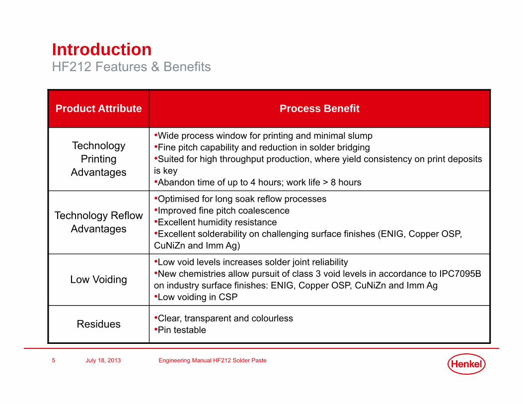
IntroductionHF212 Features & Benefits
Product Attribute Process Benefit
Technology Printing
Advantages
•Wide process window for printing and minimal slump•Fine pitch capability and reduction in solder bridging•Suited for high throughput production, where yield consistency on print deposits is key•Abandon time of up to 4 hours; work life > 8 hours
Technology Reflow Advantages
•Optimised for long soak reflow processes•Improved fine pitch coalescence•Excellent humidity resistance•Excellent solderability on challenging surface finishes (ENIG, Copper OSP, CuNiZn and Imm Ag)
Low Voiding
•Low void levels increases solder joint reliability•New chemistries allow pursuit of class 3 void levels in accordance to IPC7095Bon industry surface finishes: ENIG, Copper OSP, CuNiZn and Imm Ag•Low voiding in CSP
Residues •Clear, transparent and colourless•Pin testable

July 18, 2013 Engineering Manual HF212 Solder Paste6
Operating ParametersPrint Process Window (97SCHF212DAP88.5)
0.3mm & 0.5mm round apertures (125µm stencil)
Speed (mm/s)
Pre
ssu
re (
kg
/cm
)
1501251007550
0.4
0.3
0.2
> – – – < 1
1 22 33 4
4
CpkRound0.3mm
Speed (mm/s)
Pre
ssu
re (
kg
/cm
)
1501251007550
0.4
0.3
0.2
> – – – – < 2.0
2.0 2.52.5 3.03.0 3.53.5 4.0
4.0
CpkRound0.5mm
Speed (mm/s)
Pre
ssu
re (
kg
/cm
)
1501251007550
0.4
0.3
0.2
> – – – – < -1
-1 00 11 22 3
3
CpkRound0.3mm
Speed (mm/s)
Pre
ssu
re (
kg
/cm
)
1501251007550
0.4
0.3
0.2
> – – – < 1
1 22 33 4
4
CpkRound0.5mm
Separation Speed >20mm/s 0.3mm Round Apertures Separation Speed >20mm/s 0.5mm Round Apertures
Separation Speed <5mm/s 0.3mm Round Apertures Separation Speed <5mm/s 0.5mm Round Apertures
Excellent printing in the range 50 – 150mm/s

July 18, 2013 Engineering Manual HF212 Solder Paste7
Operating ParametersAbandon Time
• Process flow for Henkel standard abandon time test as shown below• 0.5 mm CSP (280 µm apertures) deposits measured
Pasteadded to stencil Paste kneaded Dry under
stencil wipe
Print 10 PCBsVolumesMeasured
Dry understencil wipe
Printer left for60 minutes* Print 10 PCBs
*Abandon repeated for 120 and 240 minutes & 72 hours respectively

July 18, 2013 Engineering Manual HF212 Solder Paste8
Operating ParametersAbandon Time (25C/50%RH) 1,2 & 4 hours
• Excellent abandon time resistance• No knead cycle required after 2 hours abandon• Single knead stroke required after 4 hours abandon
37332925211713951
160
140
120
100
80
60
40
20
0
Observation
Indi
vidu
al V
alue _
X=93.5
0 Hours 1 Hour 2 Hours 4 Hours
0.5Vnom
Vnom
1.5Vnom
1
I Chart of Volume (%) by Abandon Status

July 18, 2013 Engineering Manual HF212 Solder Paste9
Operating ParametersAbandon Time after 2hours
•Superior paste capability without under stencil wipe after 2 hours abandon•Cpk after 2 hour abandon = 4.07 (6σ (0.002ppm defect rate) Cpk >2)
14012611298847056
LSL Target USL
LSL 50Target 100USL 150Sample Mean 100.179Sample N 1680StDev (Within) 4.07744StDev (O v erall) 5.09759
Process Data
C p 4.09C PL 4.10C PU 4.07C pk 4.07
Pp 3.27PPL 3.28PPU 3.26Ppk 3.26C pm 3.27
O v erall C apability
Potential (Within) C apability
PPM < LSL 0.00PPM > USL 0.00PPM Total 0.00
O bserv ed PerformancePPM < LSL 0.00PPM > USL 0.00PPM Total 0.00
Exp. Within PerformancePPM < LSL 0.00PPM > USL 0.00PPM Total 0.00
Exp. O v erall Performance
WithinOverall
Process Capability of Volume % After 2 Hour Abandon

July 18, 2013 Engineering Manual HF212 Solder Paste10
Operating ParametersAbandon Time (25C/50%RH) 72 hours
191715131197531
160
140
120
100
80
60
40
20
0
Observation
Indi
vidu
al V
alue
_X=84.6
0 Hours 72 Hours
0.5Vnom
Vnom
1.5Vnom
1
1
I Chart of Volume (%) by Abandon Status
• Excellent abandon time resistance• Only 3 knead strokes required after 72 hours abandon

July 18, 2013 Engineering Manual HF212 Solder Paste11
• HF212 solder pastes show exceptional abandon time resistance• On fine pitch devices only minimal knead strokes are required after extended
machine down times• On coarser pitch deposits it is expected that the first print after abandon can
in normal circumstances be perfectly acceptable for production quality
Operating ParametersAbandon Time (25C/50%RH) 72 hours
SMT connector: 1st Print after 72 hours abandon 0.5mm CSP: 4th Print after 72 hours abandon

July 18, 2013 Engineering Manual HF212 Solder Paste12
Operating ParametersContinuous Print
• Process flow for Henkel standard continuous print test as shown below• 0.5 mm CSP (280 µm apertures) deposits measured
Pasteadded to stencil Paste kneaded Dry under
stencil wipe
Print 10 PCBs Volumesmeasured
Blank stencilinserted
Print for 8 hours Print 10 PCBs Volumes
measured

July 18, 2013 Engineering Manual HF212 Solder Paste13
Operating ParametersContinuous Print – 8hours
•No impact on print performance after 8 hours printing
191715131197531
160
140
120
100
80
60
40
20
0
Observation
Indi
vidu
al V
alue
_X=99.4
0 Hour 8 Hours
0.5Vnom
Vnom
1.5Vnom
I Chart of Volume (%) by Continuous Print Status

July 18, 2013 Engineering Manual HF212 Solder Paste14
Operating ParametersContinuous Print – 8hours
•No impact on print performance after 8 hours printing•Cpk after 8 hour continuous = 4.44 (6σ (0.002ppm defect rate) Cpk >2)
14313011710491786552
LSL Target USL
LSL 50Target 100USL 150Sample Mean 99.44Sample N 1680StDev (Within) 3.71022StDev (O v erall) 4.66631
Process Data
C p 4.49C PL 4.44C PU 4.54C pk 4.44
Pp 3.57PPL 3.53PPU 3.61Ppk 3.53C pm 3.55
O v erall C apability
Potential (Within) C apability
PPM < LSL 0.00PPM > USL 0.00PPM Total 0.00
O bserv ed PerformancePPM < LSL 0.00PPM > USL 0.00PPM Total 0.00
Exp. Within PerformancePPM < LSL 0.00PPM > USL 0.00PPM Total 0.00
Exp. O v erall Performance
WithinOverall
Process Capability of Volume % after 8 Hours Continuous Printing

July 18, 2013 Engineering Manual HF212 Solder Paste15
Operating ParametersSlump
• Slump evaluation was performed in accordance with IPC-TM-650 2.4.35
• First spacing with no bridge recorded after 15mins at 150C
Aperture 0.63 x 2.03mm
0.33 x 2.03mm
Pass mark 0.63mm 0.30mm
Initial (Room Temperature) 0.33mm 0.20mm
HF212 Result 0.33mm 0.20mm

July 18, 2013 Engineering Manual HF212 Solder Paste16
Operating ParametersTack Force
• Test to JIS-Z-3284 test method and Malcom Tackiness Tester TK1
2520151050
180
160
140
120
100
80
60
40
20
0
Hours
Tack
(g
F)
HF212Reference PasteTarget Minimum
Paste
Scatterplot of Tack (g F) vs Hours

July 18, 2013 Engineering Manual HF212 Solder Paste17
Operating ParametersReflow Process Window (Air)• Henkel Loctite HF212 solder paste offers halogen containing reflow performance in a
truly halogen free formulation• There is no single profile that works for all applications and each process should be
assessed individually, under laboratory conditions the following profiles have been found to give good results
• These process window guidelines are suitable for both DAP & AGS powder including standard SAC, high reliability 90iSC and low Ag alloys
•Reflow KeyGood ReflowAcceptable reflow, although some care needed for very fine pitch componentsAcceptable reflow for most components
Linear Profile
0
50
100
150
200
250
300
0 1 2 3 4 5 6 7 8 9 10
Time (min)
Tem
pera
ture
(°C
)
Good reflow
Acceptable reflow, although care needed for fine pitch components
Acceptable reflow for some components
Soak Profile
0
50
100
150
200
250
300
0 1 2 3 4 5 6 7 8 9 10
Time (min)
Tem
pera
ture
(°C
)
Good reflow
Acceptable reflow, although care needed for fine pitch components
Acceptable reflow for some components

July 18, 2013 Engineering Manual HF212 Solder Paste18
Operating ParametersReflow Process Performance (Long-Hot Soak)
• Example profile for 97SCHF212DAP88.5 Reflow Testing
0
50
100
150
200
250
300
0 50 100 150 200 250 300 350 400 450 500
Time (s)
Tem
pera
ture
(C)
July 18, 2013 Engineering Manual HF212 Solder Paste19
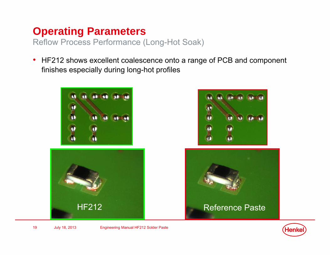
Operating ParametersReflow Process Performance (Long-Hot Soak)
• HF212 shows excellent coalescence onto a range of PCB and component finishes especially during long-hot profiles
HF212 Reference Paste

July 18, 2013 Engineering Manual HF212 Solder Paste20
Operating ParametersReflow Process Window
• HF212 Flux Medium has been optimised for excellent wetting onto difficult to solder surfaces such as CuNiZn commonly used in RF shield applications
HF212 optimised for shield wetting
Reference pasteexhibiting poor wetting

July 18, 2013 Engineering Manual HF212 Solder Paste21
Operating ParametersSolder Balling
• Solder balling performance as been assessed in accordance with an extended version of IPC-TM-650 2.4.4.3
• Clear and colourless residues observed post-reflow
Initial 24hrs 25C 50% RH
Preferred Pass Preferred Pass
July 18, 2013 Engineering Manual HF212 Solder Paste22
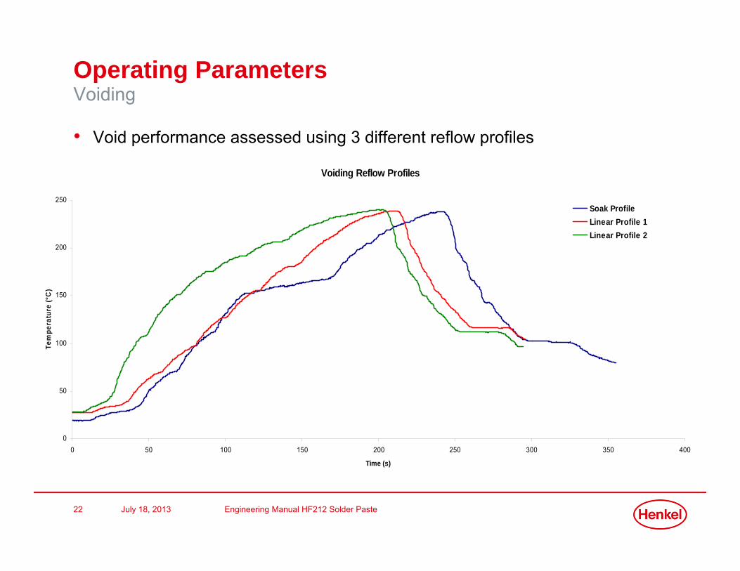
Operating ParametersVoiding
• Void performance assessed using 3 different reflow profiles
Voiding Reflow Profiles
0
50
100
150
200
250
0 50 100 150 200 250 300 350 400
Time (s)
Tem
pera
ture
(°C
)
Soak Profile Linear Profile 1Linear Profile 2

July 18, 2013 Engineering Manual HF212 Solder Paste23
Operating ParametersVoiding
ProfilePaste
SoakLinear Profile 2Linear Profile 1Reference PasteHF212Reference PasteHF212Reference PasteHF212
20
15
10
5
0
IPC
Voi
ding
Class 3
Class 2
Class 1
Boxplot of IPC Voiding Percentage
ProfilePaste
SoakLinear Profile 2Linear Profile 1Reference PasteHF212Reference PasteHF212Reference PasteHF212
9
8
7
6
5
4
3
2
1
0
Voi
d Si
ze
Boxplot of Void Size
• HF212 shows low levels of voiding over a range of profiles• Void Percentage analysed in accordance with IPC7095B
HF212 meets IPC7095B class 3

July 18, 2013 Engineering Manual HF212 Solder Paste24
HF212 Reliability and Specification TestingFlux reliability
Standard Test Result
ANSI/J-STD-004b
Cu Corrosion Pass
Cu Mirror Pass
Halogen Pass (none detected)
Surface Insulation Resistance Pass
Flux classification ROL0
HF212 J-std004b classification ROL0

July 18, 2013 Engineering Manual HF212 Solder Paste25
HF212 Reliability and Specification TestingSGS Report
• SGS report for HF212• To meet halogen free requirements,
Br<900ppm, Cl <900ppm, and combined <1500ppm
• Halogen – Fluorine - ND• Halogen – Chorine - ND• Halogen – Bromine – ND• Halogen – Iodine – ND
HF212 has no detectable halogen and is designated as halogen free

July 18, 2013 Engineering Manual HF212 Solder Paste26
HF212 Reliability and Specification TestingCleaning
Current Status (June 13th 2013)
• Zestron: Cleaning in accordance to • IPC A-610E• J-STD-001E• IPC-TM-650:
• We have completed the cleaning trials and have provided it to our MKT department for final approval. All the fluxes were easily cleaned using our standard Defluxing chemistries.
• Message from Kyzen:
• Samples were started testing last week. Should have results in two to three weeks.

July 18, 2013 Engineering Manual HF212 Solder Paste27
HF212: Performance Summary
• Halogen-free flux: passes IC with pretreatment IPC-TM-650 2.3.34/EN14582• Halogen-free flux classification: ANSI/J-STD-004 Rev. B for a type ROL0
classification• Suitable for fine pitch, high speed printing up to 150mm/s (6”/s)• Enclosed head compatible*• Optimized for long soak reflow profiles• Improved fine pitch coalescence• Excellent humidity resistance• Excellent solderability on challenging surface finishes, including CuNiZn• Colorless residues for easy post-reflow inspection
*requires vacuum (v) version

Thank you!