ENGINEERING GRAPHICS & DESIGN MANUAL (3110013)
21
In the course of Engineering Graphics and Design (3110013) students should be able to think in core concept of their engineering application of various sketching and drawing techniques, their use and its application to develop thinking ability towards problem solving direction. Through this laboratory manual Students will understand the problem, resolve it and represent the solution by graphics or drawing weather industrial or academic problem. Course Outcome: After learning the course the students will be able to: 1. Understand the standards and common cases as well as dimensioning in technical drawings development. 2. Able to develop multi-aspect sketches, sectional views and geometries of the development of design projects. 3. Visualize objects in all dimensions and learn displaying techniques for graphical communication in design process. 4. Use computer software for engineering drawing. ENGINEERING GRAPHICS & DESIGN MANUAL (3110013) GOVT. ENGG. COLLEGE, VALSAD. MECHANICAL ENGG. DEPT. ( FOR EVEN TERM–2019-20 )
Transcript of ENGINEERING GRAPHICS & DESIGN MANUAL (3110013)
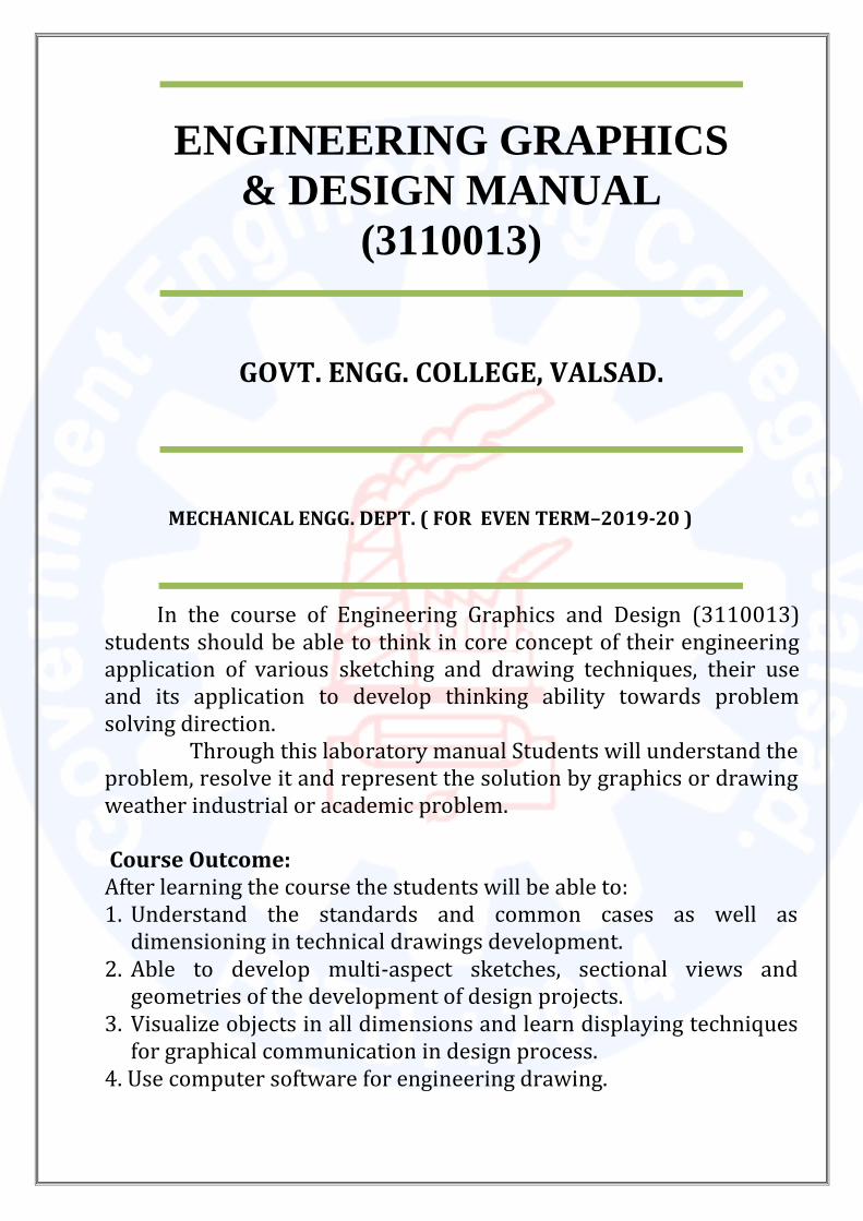
In the course of Engineering Graphics and Design (3110013) students should be able to think in core concept of their engineering application of various sketching and drawing techniques, their use and its application to develop thinking ability towards problem solving direction.
Through this laboratory manual Students will understand the problem, resolve it and represent the solution by graphics or drawing weather industrial or academic problem. Course Outcome: After learning the course the students will be able to: 1. Understand the standards and common cases as well as
dimensioning in technical drawings development. 2. Able to develop multi-aspect sketches, sectional views and
geometries of the development of design projects. 3. Visualize objects in all dimensions and learn displaying techniques
for graphical communication in design process. 4. Use computer software for engineering drawing.
ENGINEERING GRAPHICS
& DESIGN MANUAL
(3110013)
GOVT. ENGG. COLLEGE, VALSAD.
MECHANICAL ENGG. DEPT. ( FOR EVEN TERM–2019-20 )
GOVERNMENT ENGINEERING COLLEGE, VALSAD MECHANICAL ENGINEERING DEPARTMENT
ENGINEERING GRAPHICS & DESIGN MANUAL (3110013)
YEAR: 2019-20
W.e.f.: 20 / 01/ 2020
Subject coordinator: - Prof. B.G. Patel & Prof. J. P. Tandel Page 2
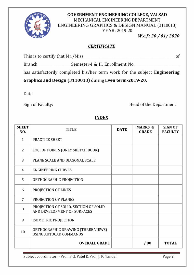
CERTIFICATE
This is to certify that Mr./Miss_____________________________________________________ of
Branch __________________ Semester-I & II, Enrollment No.__________________________,
has satisfactorily completed his/her term work for the subject Engineering
Graphics and Design (3110013) during Even term-2019-20.
Date: Sign of Faculty: Head of the Department
INDEX
SHEET NO.
TITLE DATE MARKS &
GRADE SIGN OF
FACULTY
1 PRACTICE SHEET
2 LOCI OF POINTS (ONLY SKETCH BOOK)
3 PLANE SCALE AND DIAGONAL SCALE
4 ENGINEERING CURVES
5 ORTHOGRAPHIC PROJECTION
6 PROJECTION OF LINES
7 PROJECTION OF PLANES
8 PROJECTION OF SOLID, SECTION OF SOLID AND DEVELOPMENT OF SURFACES
9 ISOMETRIC PROJECTION
10 ORTHOGRAPHIC DRAWING (THREE VIEWS) USING AUTOCAD COMMANDS
OVERALL GRADE / 80 TOTAL

GOVERNMENT ENGINEERING COLLEGE, VALSAD MECHANICAL ENGINEERING DEPARTMENT
ENGINEERING GRAPHICS & DESIGN MANUAL (3110013)
YEAR: 2019-20
W.e.f.: 20 / 01/ 2020
Subject coordinator: - Prof. B.G. Patel & Prof. J. P. Tandel Page 3
Reference books:
1. A Text Book of Engineering Graphics by P.J.Shah S.Chand & Company Ltd., New Delhi
2. Elementary Engineering Drawing by N.D.Bhatt Charotar Publishing House, Anand
3. A text book of Engineering Drawing by R.K.Dhawan, S.Chand & Company Ltd., New Delhi
4. A text book of Engineering Drawing by P.S.Gill, S.K.Kataria & sons, Delhi 5. Engineering Drawing by B. Agrawal and C M Agrawal, Tata McGraw Hill, New
Delhi Drawing Equipments & Materials (for laboratory work):
Set square » 45o & 30o - 60o (With inbuilt French curve) Instrument Box (Engineering Compass Box) Eraser, Sharpener etc. 0.5 mm clutch pencil ( With H & 2H lead only ) Drawing clips (pins) Two Sketch Books (A3 size) Stencils, Circle master, Protractor & Scales Drawing Sheets of A2 size.
How to begin your drawing?
Clean the drawing board and all the drawing instruments using handkerchief/napkin.
Fix the drawing sheet on the drawing board (table). Draw border lines on sheet. Spacing of drawing between two problem/views is to be planned
before the commencement of the drawing. Write the problem number on the left top and then commence the
drawing work.

GOVERNMENT ENGINEERING COLLEGE, VALSAD MECHANICAL ENGINEERING DEPARTMENT
ENGINEERING GRAPHICS & DESIGN MANUAL (3110013)
YEAR: 2019-20
W.e.f.: 20 / 01/ 2020
Subject coordinator: - Prof. B.G. Patel & Prof. J. P. Tandel Page 4
POINTS TO REMEMBER:
ALWAYS DO: 1. Clean hands are the first necessity. 2. Begin the work after wiping-off the drawing board. 3. Keep your drawing instruments clean. 4. Use appropriate drawing instruments. 5. Maintain the sharpness of pencil by periodically sharpening it. 6. Keep handkerchief to clean any dirt on the drawing sheet.
DON’TS: 1. Never use cheap quality pencil and eraser on drawing sheet. 2. Never use the scale as a rule for drawing lines or taking
measurements directly. 3. Never put either end of the pencil into the mouth. 4. Never sharpen the pencil over the drawing board or sheet. 5. The sliding equipment on the drawing sheet, namely mini-drafter,
set squares and protractor must be cleaned properly every time and sliding should be reduced to minimum.
6. Never keep the instrument viz. compass, divider etc. outside the instrument box, while not in use.
TERM WORK: Each student is requested to prepare following as Term Work:
1. Sketch Book a) All the problems which are to be drawn in the sheets are to be
solved first in the sketch book. b) Completion of all problems of a sheet in the sketch-book is
prerequisite to start the sheet. c) Student is not allowed to solve the problems in the sketch book
during the laboratory time. d) Before starting the sheet, students are required to take signature of
the Lab Faculty in the sketchbook.

GOVERNMENT ENGINEERING COLLEGE, VALSAD MECHANICAL ENGINEERING DEPARTMENT
ENGINEERING GRAPHICS & DESIGN MANUAL (3110013)
YEAR: 2019-20
W.e.f.: 20 / 01/ 2020
Subject coordinator: - Prof. B.G. Patel & Prof. J. P. Tandel Page 5
2. Sheets a) Title Block and border lines in the sheets are to be drawn at
home. No students are allowed to draw the title block and border lines during laboratory hours.
b) After taking sign in the sketch book, students have to take Starting sign of the Lab. Faculty in the title block.
c) Students are required to take suitable scale so that all the problems can be solved within the available space of the sheet.
Instructions for drawing sheet preparation: Student should draw the boundary in the pages of the sketchbook/sheet
and then solve problems. Boundary margin for sketch-book is 10 mm from all sides. Boundary margin for sheet is 40 mm from left hand side and 10 mm from remaining three sides.
Student should write the full problem in the sketchbook and draw the problem with proper dimensioning.
Lab faculty should allow the student to start their sheet- work after
checking the sketch book and correcting the mistakes, if any. Student will have to draw title block in the sheet and have to draw all the
problems within the boundary with proper dimensioning.
Student will have to write the answer in the sheet, if asked.
Student will have to write drawing scale, if different for a particular problem.
Student will have to specify the projection system that they have used.
In sheet work all the lettering and any instruction must be of capital letters. It is not allowed to use small letter and running letter.
Standard dimensioning pattern must be considered.

GOVERNMENT ENGINEERING COLLEGE, VALSAD MECHANICAL ENGINEERING DEPARTMENT
ENGINEERING GRAPHICS & DESIGN MANUAL (3110013)
YEAR: 2019-20
W.e.f.: 20 / 01/ 2020
Subject coordinator: - Prof. B.G. Patel & Prof. J. P. Tandel Page 6
LIST OF SHEETS
SHEET NO.
SHEET TITLE
1.
PRACTICE SHEET (which includes dimensioning methods, different types of line, construction of different polygon, divide the line and angle in parts, use of stencil)
2. PLANE SCALE AND DIAGONAL SCALE
3. ORTHOGRAPHIC PROJECTION
4. ENGINEERING CURVES
5. PROJECTION OF LINES
6. PROJECTION OF PLANES
7. ISOMETRIC PROJECTION
8. PROJECTION OF SOLID, SECTION OF SOLID AND DEVELOPMENT OF SURFACES

GOVERNMENT ENGINEERING COLLEGE, VALSAD MECHANICAL ENGINEERING DEPARTMENT
ENGINEERING GRAPHICS & DESIGN MANUAL (3110013)
YEAR: 2019-20
W.e.f.: 20 / 01/ 2020
Subject coordinator: - Prof. B.G. Patel & Prof. J. P. Tandel Page 7
SHEET 01:- PRACTICE SHEET
1. Title block: As shown in the figure. (Position of title block in sheet: right-bottom corner in the sheet)
GOVERNMENT ENGINEERING COLLEGE, VALSAD MECHANICAL ENGINEERING DEPARTMENT
ENGINEERING GRAPHICS & DESIGN MANUAL (3110013)
YEAR: 2019-20
W.e.f.: 20 / 01/ 2020
Subject coordinator: - Prof. B.G. Patel & Prof. J. P. Tandel Page 8
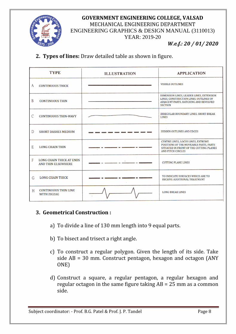
2. Types of lines: Draw detailed table as shown in figure.
3. Geometrical Construction :
a) To divide a line of 130 mm length into 9 equal parts.
b) To bisect and trisect a right angle.
c) To construct a regular polygon. Given the length of its side. Take side AB = 30 mm. Construct pentagon, hexagon and octagon (ANY ONE)
d) Construct a square, a regular pentagon, a regular hexagon and
regular octagon in the same figure taking AB = 25 mm as a common side.

GOVERNMENT ENGINEERING COLLEGE, VALSAD MECHANICAL ENGINEERING DEPARTMENT
ENGINEERING GRAPHICS & DESIGN MANUAL (3110013)
YEAR: 2019-20
W.e.f.: 20 / 01/ 2020
Subject coordinator: - Prof. B.G. Patel & Prof. J. P. Tandel Page 9
4. Dimensioning(as per BIS)
BIS (Bureau of Indian Standards) are the national standard body formed by the government of India on April 1, 1987. BIS works in association with International Standard Organization ((ISO). General Principles of dimensioning:- - All dimensions should be mentioned on drawing. - No single dimension should be repeated where unavoidable. - Mark the dimensions outside the drawing as far as possible. - Avoid dimensions to hidden lines wherever possible. - The longer dimensions should be placed outside all intermediate
dimensions, so that dimension line cannot cross extension lines. Element of dimensioning:- Student should identify and know the correct drawing of the following dimensioning elements (refer text book): - Dimension lines - Extension lines - Leader lines - Arrow heads

GOVERNMENT ENGINEERING COLLEGE, VALSAD MECHANICAL ENGINEERING DEPARTMENT
ENGINEERING GRAPHICS & DESIGN MANUAL (3110013)
YEAR: 2019-20
W.e.f.: 20 / 01/ 2020
Subject coordinator: - Prof. B.G. Patel & Prof. J. P. Tandel Page 10
Dimensioning systems:- Aligned system & unidirectional system: Figure for practice:-

GOVERNMENT ENGINEERING COLLEGE, VALSAD MECHANICAL ENGINEERING DEPARTMENT
ENGINEERING GRAPHICS & DESIGN MANUAL (3110013)
YEAR: 2019-20
W.e.f.: 20 / 01/ 2020
Subject coordinator: - Prof. B.G. Patel & Prof. J. P. Tandel Page 11
SHEET 02:- PLANE SCALE AND DIAGONAL SCALE
1. Define Representative fraction. Construct a scale of 1.5cm = 1 dm to read up to 1 meter and show on it length of 0.65 meter.
2. Construct a plain scale of R.F. = 1:100 to show meters and decimeters. Maximum measurement required is 7 meters. Indicate 5 m 7 dm on the scale.
3. On map of Valsad city 3 cm represents 1 km. construct a plain scale to measure the distance between Railway station and Tithal sea shore which is 6 km. Also indicate on scale, the distance between Railway station and GEC Valsad which is 3 km and 7 hectameters. (Note:- Only for sketch book)
4. Construct a Diagonal scale of R.F.=1/2 to show millimeter and centimeter to measure up to 35 centimeter. Show on the scale a distance of 23.6 centimeter.
5. The length of the khandala tunnel on the Mumbai-Pune expressway is 330 m. On the road map, it is shown by a 16.5 cm long line. Construct a scale to show meters and to measure up to 400 m. Show the length of a 289 meter long on the expressway.
GOVERNMENT ENGINEERING COLLEGE, VALSAD MECHANICAL ENGINEERING DEPARTMENT
ENGINEERING GRAPHICS & DESIGN MANUAL (3110013)
YEAR: 2019-20
W.e.f.: 20 / 01/ 2020
Subject coordinator: - Prof. B.G. Patel & Prof. J. P. Tandel Page 12
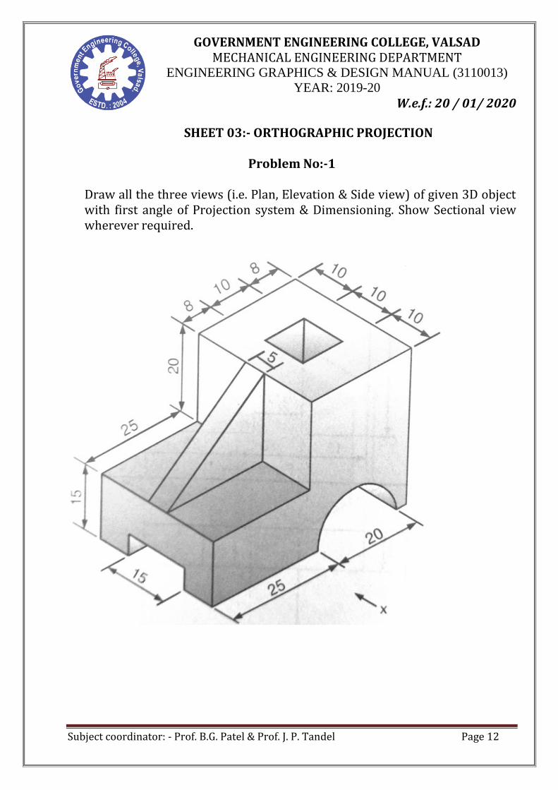
SHEET 03:- ORTHOGRAPHIC PROJECTION
Problem No:-1
Draw all the three views (i.e. Plan, Elevation & Side view) of given 3D object with first angle of Projection system & Dimensioning. Show Sectional view wherever required.

GOVERNMENT ENGINEERING COLLEGE, VALSAD MECHANICAL ENGINEERING DEPARTMENT
ENGINEERING GRAPHICS & DESIGN MANUAL (3110013)
YEAR: 2019-20
W.e.f.: 20 / 01/ 2020
Subject coordinator: - Prof. B.G. Patel & Prof. J. P. Tandel Page 13
Problem No:-2
Draw all the three views (i.e. Plan, Elevation & Sectional view) of given 3D object with first angle of Projection system & Dimensioning.

GOVERNMENT ENGINEERING COLLEGE, VALSAD MECHANICAL ENGINEERING DEPARTMENT
ENGINEERING GRAPHICS & DESIGN MANUAL (3110013)
YEAR: 2019-20
W.e.f.: 20 / 01/ 2020
Subject coordinator: - Prof. B.G. Patel & Prof. J. P. Tandel Page 14
Problem No:-3
Draw all the three views (i.e. Plan, Elevation & Side view) of given 3D object
with third angle of Projection system & Dimensioning.

GOVERNMENT ENGINEERING COLLEGE, VALSAD MECHANICAL ENGINEERING DEPARTMENT
ENGINEERING GRAPHICS & DESIGN MANUAL (3110013)
YEAR: 2019-20
W.e.f.: 20 / 01/ 2020
Subject coordinator: - Prof. B.G. Patel & Prof. J. P. Tandel Page 15
SHEET 04:-ENGINEERING CURVES
1. The distance between a fixed point and a fixed straight line is 60mm. Draw
the locus of the moving point P such that its distance from the fixed point is (i) twice its distance from a straight line, (ii) equal to its distance from a fixed straight line, (iii) half its distance from the fixed straight line. Name the three curves. (Ref:-P.J.Shah,prob-3,5.39)
2. A coin of 35 mm diameter, rolls over a horizontal table without slipping. A
point on the circumference of the coin is in contact with the table surface in the beginning and after one complete revolution. Draw the cycloidal path traced by the point. Draw tangent and normal at any point of curve. (Ref:-N.D.Bhatt, prob-52,147)
3. Draw an Archimedean spiral of 1.5 convolutions, the greatest and the least
radii being 125 mm and 35 mm respectively. Draw tangent and normal to the spiral at a point 85 mm from the pole.
(Ref:-P.J.Shah, prob-33, 5.41) 4. A string is unwound from a square of 25 mm side. Draw the locus of end P of
string for unwinding the string’s one turn. String is kept tight during unwinding operation. Draw tangent and normal to the curve at any point.

GOVERNMENT ENGINEERING COLLEGE, VALSAD MECHANICAL ENGINEERING DEPARTMENT
ENGINEERING GRAPHICS & DESIGN MANUAL (3110013)
YEAR: 2019-20
W.e.f.: 20 / 01/ 2020
Subject coordinator: - Prof. B.G. Patel & Prof. J. P. Tandel Page 16
LOCI OF POINTS (ONLY IN SKETCH BOOK)
1. OAB is an offset slider crank chain. Crank OB is 30 mm long and rotates in clockwise direction. Connecting rod AB is 128 mm long. Offset is 40 mm. draw the loci of two point P and R as shown in fig. PB = 45 mm and BR= 30mm. (Ref:-P.J.Shah, prob-12, 4.9)
2. ABCD is a four bar mechanism with the link AD as the fixed link. Driving Crank AB is 40mm long. Driven Crank DC is also 40mm long. Connecting link BC is 130mm long. Distance between A and D is 130mm. two cranks rotate in the opposite directions. Draw the loci of points P and Q for one complete revolution of the driving crank. The point P is the midpoint of the connecting link BC and point Q is 30 mm from C on BC extended. (Ref:- exam paper 2006)
3. A link AB of 72 mm length rotates about its centre in the clockwise direction. While the link completes one revolution, the insect walks across the length from one end to other. Plot the locus of the insect assuming the rotation of the link and the motion of the insect as uniform. ( Ref:-P.J.Shah, prob-19, 4.16)
4. A pendulum OC pivoted at O is 120mm long. It swings 30˚ to the right of
vertical and also 30˚ to the left vertical. Insect, initially at O reaches the point C, when the pendulum completes two oscillations. Draw the path of the insect, assuming motion of insect and of pendulum as uniform. ( Ref:-P.J.Shah, prob-23, 4.19)

GOVERNMENT ENGINEERING COLLEGE, VALSAD MECHANICAL ENGINEERING DEPARTMENT
ENGINEERING GRAPHICS & DESIGN MANUAL (3110013)
YEAR: 2019-20
W.e.f.: 20 / 01/ 2020
Subject coordinator: - Prof. B.G. Patel & Prof. J. P. Tandel Page 17
SHEET 05:-PROJECTION OF LINES
1. The top view of a straight line AB 60 mm long measure 46 mm, while the length of its front view is 53 mm. the one end A is 15 mm above H.P. and 20 mm in front of V.P. Draw projection of straight line AB and find its inclination with H.P. and V.P.(exam paper, December 2001)
2. The top view and front view of the line CD, measure 65 mm and 53 mm
respectively. The line is inclined to H.P. and to V.P by 300 and 450 respectively. The end C is on H.P. and 12 mm in front of V.P. other end D is in first quadrant. Draw the projection of a line CD and find its true length.
3. The auditorium of a collage is 100m long, 50 m wide and 20 m height. A
light point is fitted at the center of the roof and its switch is kept on the side wall of the auditorium, 1.5 m above the floor and 10 m from one of the adjacent sidewalls. Find the actual distance between the light point and switch.
4. Two mangos on a tree A & B are 1.5 m and 3.00 m above ground and
those are 1.2 m & 1.5 m from a 0.3 m thick wall but on opposite sides of it. If the distance measured between them along the ground and parallel to wall is 2.6 m, then find real distance between them by drawing their projections.

GOVERNMENT ENGINEERING COLLEGE, VALSAD MECHANICAL ENGINEERING DEPARTMENT
ENGINEERING GRAPHICS & DESIGN MANUAL (3110013)
YEAR: 2019-20
W.e.f.: 20 / 01/ 2020
Subject coordinator: - Prof. B.G. Patel & Prof. J. P. Tandel Page 18
SHEET 06:- PROJECTION OF PLANES
1. ABCD is rhombus of diagonals AC=110mm and BD=70mm, its corner A is in the H.P., and the plane is inclined to H.P. such that the plane
appears to be square. The plane of diagonal AC makes an angle of 20˚ to the V.P. Draw the projection of the plane and finds its inclination with H.P.
2. Regular pentagon ABCDE, of 30 mm sides, has its side AB in the V.P.
and inclined at an angle of 30˚ to the H.P. the corner A is 15 mm above H.P. and the corner D is 20mm in front of V.P. Draw the projection of the plane and find its inclination with V.P.
3. A circle of 50 mm diameter is resting on HP on end A of its diameter
AC which is 30˚ inclined to HP while its TV is 45˚ inclined to VP. Draw its projections.
4. A hexagonal lamina has its one side in HP and Its apposite parallel side is 25mm above HP and In VP. Draw its projections. Take side of hexagon 30 mm long.

GOVERNMENT ENGINEERING COLLEGE, VALSAD MECHANICAL ENGINEERING DEPARTMENT
ENGINEERING GRAPHICS & DESIGN MANUAL (3110013)
YEAR: 2019-20
W.e.f.: 20 / 01/ 2020
Subject coordinator: - Prof. B.G. Patel & Prof. J. P. Tandel Page 19
SHEET 07:- PROJECTION OF SOLID, SECTION OF SOLID AND DEVELOPMENT OF SURFACES
1. A cone 40 mm diameter and 50 mm axis is resting on one generator on Hp
which makes 30˚ inclinations with VP. Draw its projections. 2. A hexagonal prism is resting on H.P. on its base with two edges/ sides of base
parallel to V.P. It is cut by A.I.P. (Auxiliary cutting plane) perpendicular to
V.P. and inclined to H.P. by 45˚ passing through a point of axis 40 mm above the base. Draw three principle projections and fine the true shape of section. Take side of base 25mm and height 50 mm.
3. A pentagonal pyramid, side of the base 40 mm and height 80mm, is resting
on H.P. on its base with one of the edges of the base away from VP. Is parallel to VP. It’s cut by an A.I.P. bisecting the axis, the distance of the section plane from the apex being 20mm.draw the elevation and sectional plan of the pyramid and draws the true shape of the section. Find the inclination of the sectional plane with the HP.
4. A square prism, side of base 50 mm & height 70 mm, is resting on H.P. on its
base with all vertical faces equally inclined to V.P. Hole of 60 mm diameter is drilled centrally through the prism. Axis of the hole is perpendicular to V.P. Draw the development of only the lateral surfaces of the prism. (ref:- P.J.Shah) (Note:- Draw only in sketch book)
5. The development of a cone is a semicircle of 80 mm radius having a circular
hole of 80 mm diameter. Draw the plan and elevation of the cone along with periphery of a circular hole shown on them. (ref:- P.J.Shah ) (Note:- Draw only in sketch book)
6. A right regular pentagonal pyramid (30x60) is resting on H.P. on its base
with one of the sides of base perpendicular to V.P. It is cut by a cutting plane
A.I.P. making 60˚ with HP and bisecting the axis. Draw the development of the cut pyramid. (Ref:-P.J.Shah, prob-5, 13.5)

GOVERNMENT ENGINEERING COLLEGE, VALSAD MECHANICAL ENGINEERING DEPARTMENT
ENGINEERING GRAPHICS & DESIGN MANUAL (3110013)
YEAR: 2019-20
W.e.f.: 20 / 01/ 2020
Subject coordinator: - Prof. B.G. Patel & Prof. J. P. Tandel Page 20
SHEET 08:- ISOMETRIC PROJECTION AND ISOMETRIC VIEWS
Draw isometric views/drawing projection from given views.
Problem No:-1 Problem No:-2
Problem No:-3 Draw isometric drawing by using Isometric scale.
GOVERNMENT ENGINEERING COLLEGE, VALSAD MECHANICAL ENGINEERING DEPARTMENT
ENGINEERING GRAPHICS & DESIGN MANUAL (3110013)
YEAR: 2019-20
W.e.f.: 20 / 01/ 2020
Subject coordinator: - Prof. B.G. Patel & Prof. J. P. Tandel Page 21
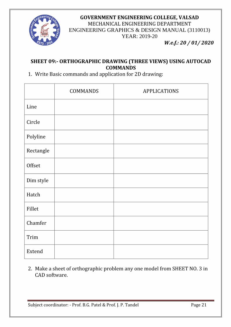
SHEET 09:- ORTHOGRAPHIC DRAWING (THREE VIEWS) USING AUTOCAD
COMMANDS 1. Write Basic commands and application for 2D drawing:
COMMANDS APPLICATIONS
Line
Circle
Polyline
Rectangle
Offset
Dim style
Hatch
Fillet
Chamfer
Trim
Extend
2. Make a sheet of orthographic problem any one model from SHEET NO. 3 in
CAD software.