Engine Manual: E15 (1992-95 Master)
40
E15 Motor Safety, Operation, Maintenance & Parts Manual 1992 LT30 rev. C4 - F3.00 1992 LT40 rev. C5 - F4.00 1992 LT30HD rev. C7 - F7.00 1992 LT40HD rev. C7 - F7.00 Safety is our #1 concern! Read and understand all safety information and instructions before oper- ating, setting up or maintaining this machine. October 1994 Form #652
Transcript of Engine Manual: E15 (1992-95 Master)
E15 MotorSafety, Operation, Maintenance
& Parts Manual
1992 LT30 rev. C4 - F3.001992 LT40 rev. C5 - F4.001992 LT30HD rev. C7 - F7.001992 LT40HD rev. C7 - F7.00
Safety is our #1 concern! Read and understandall safety information and instructions before oper-ating, setting up or maintaining this machine.
October 1994Form #652
Table of Contents Section-Page
SECTION 1 SAFETY & GENERAL INFORMATION 1-1
1.1 Battery Handling ....................................................................................1-11.2 Electric Sawmill Wiring .........................................................................1-21.3 Phase Converter......................................................................................1-5
SECTION 2 OPERATION 2-1
2.1 Starting The Motor .................................................................................2-1
SECTION 3 MAINTENANCE 3-1
3.1 Battery ....................................................................................................3-13.2 Alternator Belt ........................................................................................3-23.3 Drive Belt Adjustment............................................................................3-3
SECTION 4 REPLACEMENT PARTS 4-1
4.1 How To Use The Parts List ....................................................................4-14.2 Sample Assembly ...................................................................................4-14.3 Motor Starter Assembly .........................................................................4-24.4 Motor Assembly .....................................................................................4-4
SECTION 5 ELECTRICAL INFORMATION 5-1
5.1 Electrical Symbol Diagram, LT30/LT40 E15 ........................................5-15.2 Electrical Symbol Diagram, LT30/LT40 E15s ......................................5-25.3 Electrical Symbol Diagram, LT30HD/LT40HD E15 (Rev. C7 - E6)....5-35.4 Electrical Symbol Diagram, LT30HD/LT40HD E15 (Rev. E7-F7) ......5-45.5 Electrical Symbol Diagram, LT30HD/LT40HD E15s (Rev. C7-E6) ....5-55.6 Electrical Symbol Diagram, LT30HD/LT40HD E15s (Rev. E7-F7).....5-65.7 Electrical Components, LT30/LT40 E15/E15s ......................................5-75.8 Electrical Components, LT30HD/LT40HD E15/E15s (Rev. C7 - E6) ..5-95.9 Electrical Components, LT30HD/LT40HD E15/E15s (Rev. E7+)......5-115.10 Battery Specifications, LT30/LT40 E15/E15s .....................................5-135.11 Battery Specifications, LT30HD/LT40HD E15/E15s..........................5-145.12 Wiring Diagram, LT30/LT40 E15 .......................................................5-155.13 Wiring Diagram, LT30/LT40 E15s......................................................5-165.14 Wiring Diagram, LT30HD/LT40HD E15............................................5-175.15 Wiring Diagram, LT30HD/LT40HD E15s ..........................................5-18
ii E1592doc072311 Table of Contents

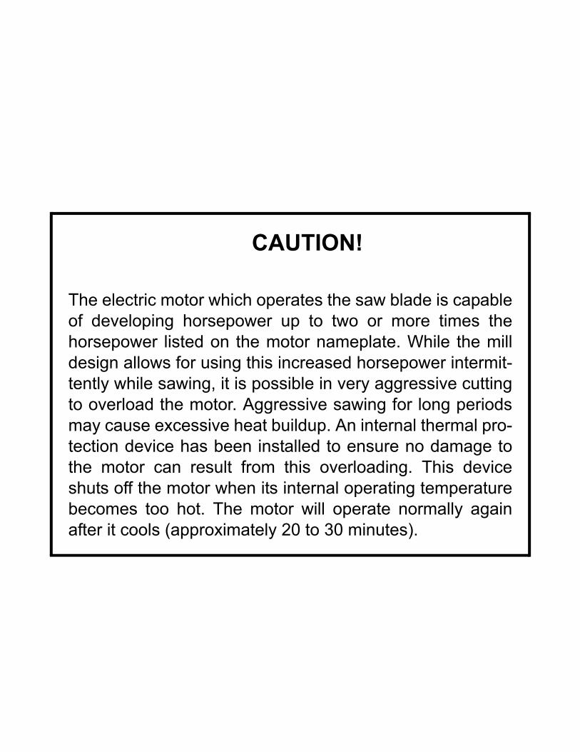
CAUTION!
The electric motor which operates the saw blade is capableof developing horsepower up to two or more times thehorsepower listed on the motor nameplate. While the milldesign allows for using this increased horsepower intermit-tently while sawing, it is possible in very aggressive cuttingto overload the motor. Aggressive sawing for long periodsmay cause excessive heat buildup. An internal thermal pro-tection device has been installed to ensure no damage tothe motor can result from this overloading. This deviceshuts off the motor when its internal operating temperaturebecomes too hot. The motor will operate normally againafter it cools (approximately 20 to 30 minutes).
Safety & General InformationBattery Handling 1
SECTION 1 SAFETY & GENERAL INFORMATION
This symbol calls your attention to instructions concerning your personal safety. Be sureto observe and follow these instructions. This symbol accompanies a signal word. Theword DANGER refers to hazards that can cause death or serious, irreversible personalinjury. The word WARNING suggests a safety hazard that can cause personal injury.CAUTION refers to hazards that can cause damage to the equipment or property only.
Read all safety instructions before operating this equipment and observe all safety warn-ings! Read the manufacturer’s operation manual and observe any additional safety warn-ings applicable to the specific make and model you have purchased.
1.1 Battery Handling
WARNING! Batteries can explode when charging or boost-ing. Always wear eye protection.
WARNING! Keep cigarettes, flames or sparks away frombattery.
WARNING! Charge the battery in a well-ventilated area. Donot attempt to charge a frozen battery.
CAUTION! Place a rag over battery vent holes when han-dling to avoid electrolyte squirting from holes.
Safety & General Information E1592doc072311 1-1
Safety & General InformationElectric Sawmill Wiring1
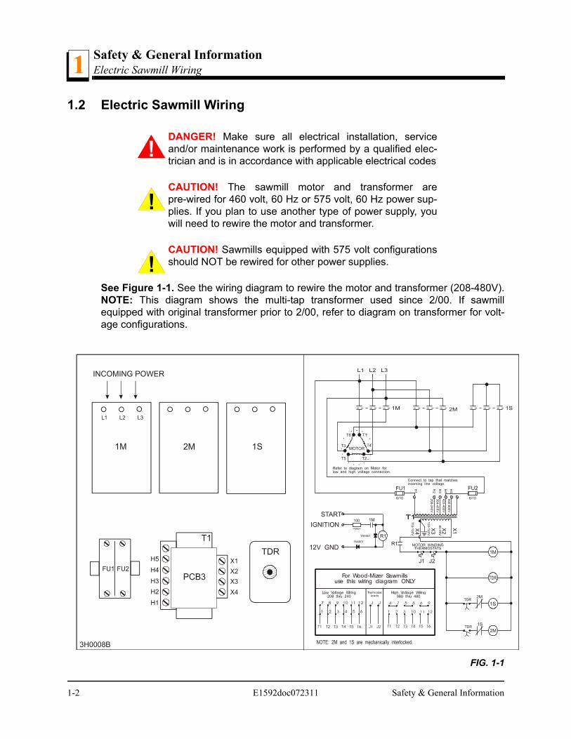
1.2 Electric Sawmill Wiring
DANGER! Make sure all electrical installation, serviceand/or maintenance work is performed by a qualified elec-trician and is in accordance with applicable electrical codes
CAUTION! The sawmill motor and transformer arepre-wired for 460 volt, 60 Hz or 575 volt, 60 Hz power sup-plies. If you plan to use another type of power supply, youwill need to rewire the motor and transformer.
CAUTION! Sawmills equipped with 575 volt configurationsshould NOT be rewired for other power supplies.
See Figure 1-1. See the wiring diagram to rewire the motor and transformer (208-480V).NOTE: This diagram shows the multi-tap transformer used since 2/00. If sawmillequipped with original transformer prior to 2/00, refer to diagram on transformer for volt-age configurations.
FIG. 1-1
1M
L1 L2 L3
2M
T1
X1H4FU1 FU2 X2
H3 X3
X4
H1
TDR
1S
INCOMING POWER
START
IGNITION
12V GND MOTOR WINDINGTHERMOSTATS
1M
R1
1S
2M
Connect to tap that matchesincoming line voltage.
Refer to diagram on Motor forlow and high voltage connection.
6/10
FU1
T1
T4
T2
6/10
R1
1M
J1 J2
X1
FU2
MOTORT3
T5
T6
For Wood-Mizer Sawmillsuse this wiring diagram ONLY
Low Voltage Wiring208 thru 240
High Voltage Wiring380 thru 480
ThermostatLeads
H4
3H0008B
208
-240
V
364
-416
V
420
-480
V
500
-600
VH
5
H3
H2
H1
H2
H5
PCB3
X4
X2
X3
110
-13
0V
10
0-1
20
V
85-9
9V
1-2 E1592doc072311 Safety & General Information
Safety & General InformationElectric Sawmill Wiring 1
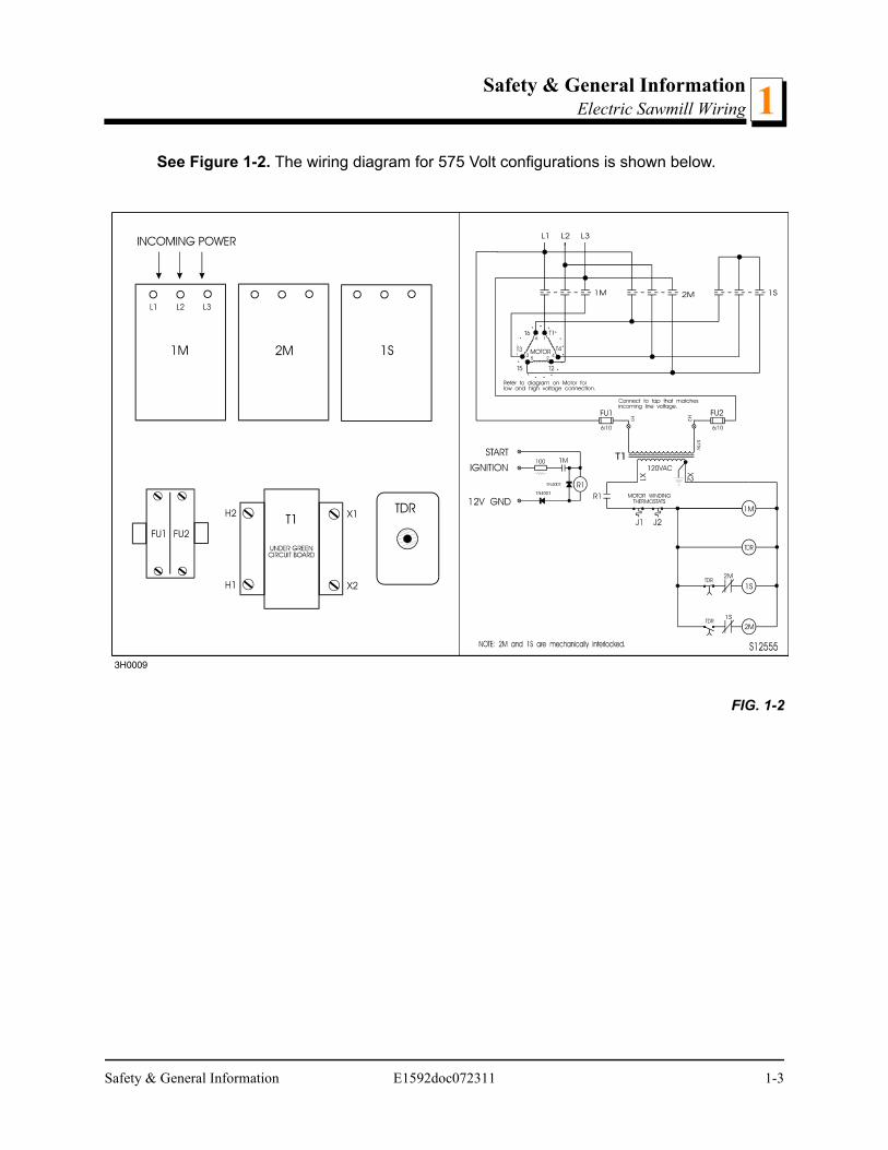
See Figure 1-2. The wiring diagram for 575 Volt configurations is shown below.
FIG. 1-2
Safety & General Information E1592doc072311 1-3
Safety & General InformationElectric Sawmill Wiring1
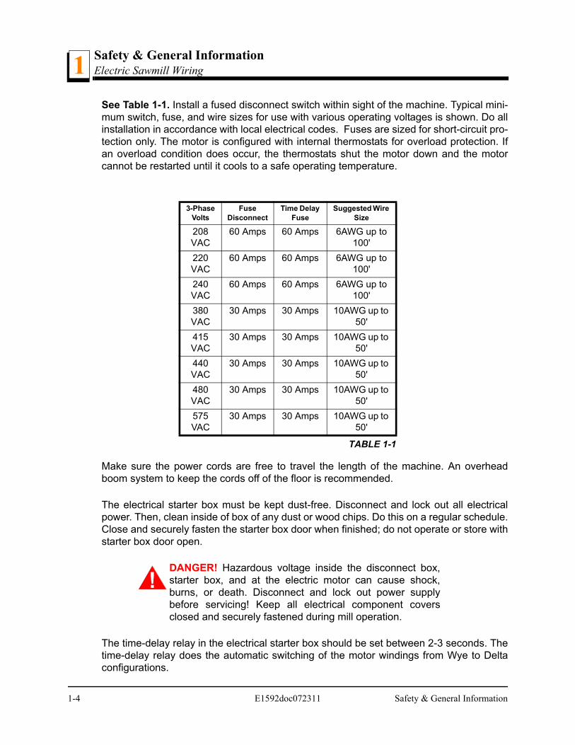
See Table 1-1. Install a fused disconnect switch within sight of the machine. Typical mini-mum switch, fuse, and wire sizes for use with various operating voltages is shown. Do allinstallation in accordance with local electrical codes. Fuses are sized for short-circuit pro-tection only. The motor is configured with internal thermostats for overload protection. Ifan overload condition does occur, the thermostats shut the motor down and the motorcannot be restarted until it cools to a safe operating temperature.
Make sure the power cords are free to travel the length of the machine. An overheadboom system to keep the cords off of the floor is recommended.
The electrical starter box must be kept dust-free. Disconnect and lock out all electricalpower. Then, clean inside of box of any dust or wood chips. Do this on a regular schedule.Close and securely fasten the starter box door when finished; do not operate or store withstarter box door open.
DANGER! Hazardous voltage inside the disconnect box,starter box, and at the electric motor can cause shock,burns, or death. Disconnect and lock out power supplybefore servicing! Keep all electrical component coversclosed and securely fastened during mill operation.
The time-delay relay in the electrical starter box should be set between 2-3 seconds. Thetime-delay relay does the automatic switching of the motor windings from Wye to Deltaconfigurations.
3-Phase Volts
FuseDisconnect
Time Delay Fuse
Suggested Wire Size
208 VAC
60 Amps 60 Amps 6AWG up to 100'
220 VAC
60 Amps 60 Amps 6AWG up to 100'
240 VAC
60 Amps 60 Amps 6AWG up to 100'
380 VAC
30 Amps 30 Amps 10AWG up to 50'
415 VAC
30 Amps 30 Amps 10AWG up to 50'
440 VAC
30 Amps 30 Amps 10AWG up to 50'
480 VAC
30 Amps 30 Amps 10AWG up to 50'
575 VAC
30 Amps 30 Amps 10AWG up to 50'
TABLE 1-1
1-4 E1592doc072311 Safety & General Information
Safety & General InformationPhase Converter 1
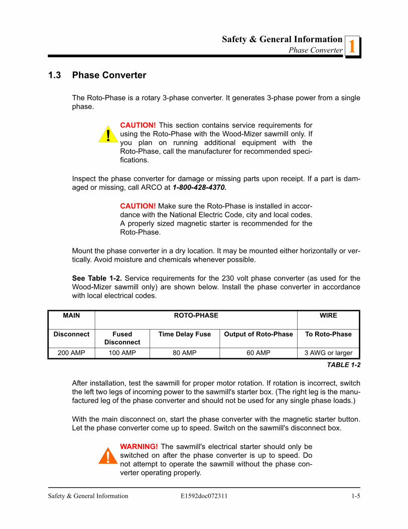
1.3 Phase Converter
The Roto-Phase is a rotary 3-phase converter. It generates 3-phase power from a singlephase.
CAUTION! This section contains service requirements forusing the Roto-Phase with the Wood-Mizer sawmill only. Ifyou plan on running additional equipment with theRoto-Phase, call the manufacturer for recommended speci-fications.
Inspect the phase converter for damage or missing parts upon receipt. If a part is dam-aged or missing, call ARCO at 1-800-428-4370.
CAUTION! Make sure the Roto-Phase is installed in accor-dance with the National Electric Code, city and local codes.A properly sized magnetic starter is recommended for theRoto-Phase.
Mount the phase converter in a dry location. It may be mounted either horizontally or ver-tically. Avoid moisture and chemicals whenever possible.
See Table 1-2. Service requirements for the 230 volt phase converter (as used for theWood-Mizer sawmill only) are shown below. Install the phase converter in accordancewith local electrical codes.
After installation, test the sawmill for proper motor rotation. If rotation is incorrect, switchthe left two legs of incoming power to the sawmill's starter box. (The right leg is the manu-factured leg of the phase converter and should not be used for any single phase loads.)
With the main disconnect on, start the phase converter with the magnetic starter button.Let the phase converter come up to speed. Switch on the sawmill's disconnect box.
WARNING! The sawmill's electrical starter should only beswitched on after the phase converter is up to speed. Donot attempt to operate the sawmill without the phase con-verter operating properly.
MAIN ROTO-PHASE WIRE
Disconnect Fused Disconnect
Time Delay Fuse Output of Roto-Phase To Roto-Phase
200 AMP 100 AMP 80 AMP 60 AMP 3 AWG or larger
TABLE 1-2
Safety & General Information E1592doc072311 1-5
Safety & General InformationPhase Converter1
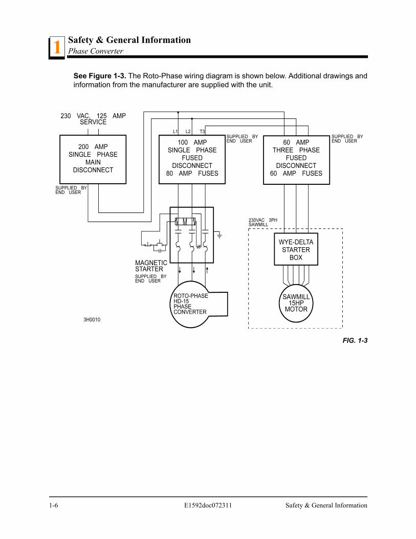
See Figure 1-3. The Roto-Phase wiring diagram is shown below. Additional drawings andinformation from the manufacturer are supplied with the unit.
FIG. 1-3
1-6 E1592doc072311 Safety & General Information
OperationStarting The Motor
Operation E1592doc072311 2-1
2
SECTION 2 OPERATION
2.1 Starting The Motor
To start the motor:
Turn the key switch on the control panel to the START position and release.
For more information, see the motor manufacturer’s operation manual.
WARNING! Do not start the motor when the clutch/brakelever is in the engaged (down) position. Always be sure theblade is disengaged and all persons are away from theblade before starting the motor.
WARNING! Make sure the carriage fwd/rev switch is in theneutral position before turning the key switch to the ON orACC position. This will prevent unintended carriage move-ment.
MaintenanceBattery3
SECTION 3 MAINTENANCE
This symbol identifies the interval (hours of operation) which each maintenance proce-dure should be performed. "AR" signifies maintenance procedures which should be per-formed as required.
3.1 Battery
Check the battery electrolyte level every 50 hours of operation. See manufacturer’s man-ual for instructions.
WARNING! Batteries contain explosive gases. Alwayswear eye protection and keep face away when charging orboosting battery. Charge battery in well-ventilated area.Keep battery away from hot or burning materials. Avoidspilling electrolyte when handling.
0
50
3-1 E1592doc060614 Maintenance
MaintenanceAlternator Belt 3
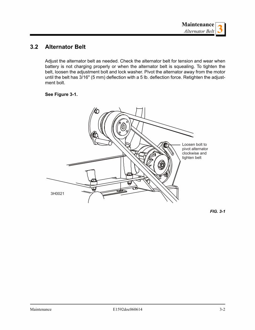
3.2 Alternator Belt
Adjust the alternator belt as needed. Check the alternator belt for tension and wear whenbattery is not charging properly or when the alternator belt is squealing. To tighten thebelt, loosen the adjustment bolt and lock washer. Pivot the alternator away from the motoruntil the belt has 3/16" (5 mm) deflection with a 5 lb. deflection force. Retighten the adjust-ment bolt.
See Figure 3-1.
FIG. 3-1
3H0021
Loosen bolt topivot alternatorclockwise andtighten belt
Maintenance E1592doc060614 3-2
MaintenanceDrive Belt Adjustment3
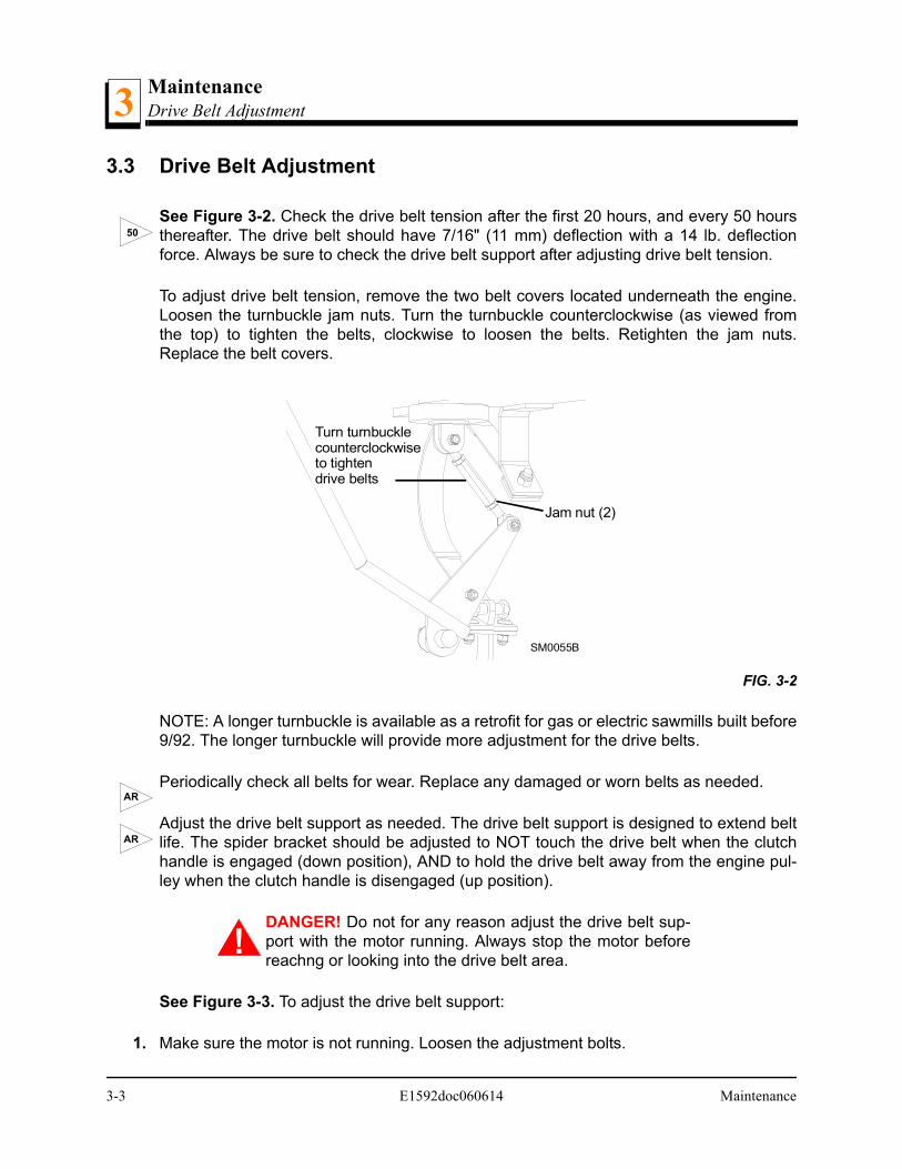
3.3 Drive Belt Adjustment
See Figure 3-2. Check the drive belt tension after the first 20 hours, and every 50 hoursthereafter. The drive belt should have 7/16" (11 mm) deflection with a 14 lb. deflectionforce. Always be sure to check the drive belt support after adjusting drive belt tension.
To adjust drive belt tension, remove the two belt covers located underneath the engine.Loosen the turnbuckle jam nuts. Turn the turnbuckle counterclockwise (as viewed fromthe top) to tighten the belts, clockwise to loosen the belts. Retighten the jam nuts.Replace the belt covers.
NOTE: A longer turnbuckle is available as a retrofit for gas or electric sawmills built before9/92. The longer turnbuckle will provide more adjustment for the drive belts.
Periodically check all belts for wear. Replace any damaged or worn belts as needed.
Adjust the drive belt support as needed. The drive belt support is designed to extend beltlife. The spider bracket should be adjusted to NOT touch the drive belt when the clutchhandle is engaged (down position), AND to hold the drive belt away from the engine pul-ley when the clutch handle is disengaged (up position).
DANGER! Do not for any reason adjust the drive belt sup-port with the motor running. Always stop the motor beforereachng or looking into the drive belt area.
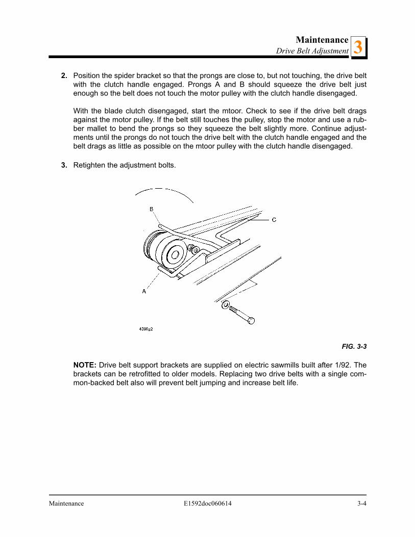
See Figure 3-3. To adjust the drive belt support:
1. Make sure the motor is not running. Loosen the adjustment bolts.
FIG. 3-2
50
Jam nut (2)
SM0055B
Turn turnbucklecounterclockwiseto tightendrive belts
AR
AR
3-3 E1592doc060614 Maintenance
MaintenanceDrive Belt Adjustment 3
2. Position the spider bracket so that the prongs are close to, but not touching, the drive beltwith the clutch handle engaged. Prongs A and B should squeeze the drive belt justenough so the belt does not touch the motor pulley with the clutch handle disengaged.
With the blade clutch disengaged, start the mtoor. Check to see if the drive belt dragsagainst the motor pulley. If the belt still touches the pulley, stop the motor and use a rub-ber mallet to bend the prongs so they squeeze the belt slightly more. Continue adjust-ments until the prongs do not touch the drive belt with the clutch handle engaged and thebelt drags as little as possible on the mtoor pulley with the clutch handle disengaged.
3. Retighten the adjustment bolts.
NOTE: Drive belt support brackets are supplied on electric sawmills built after 1/92. Thebrackets can be retrofitted to older models. Replacing two drive belts with a single com-mon-backed belt also will prevent belt jumping and increase belt life.
FIG. 3-3
Maintenance E1592doc060614 3-4
Replacement PartsHow To Use The Parts List4
SECTION 4 REPLACEMENT PARTS
4.1 How To Use The Parts List
Use the table of contents or the index to locate the assembly that contains the partyou need.
Go to the appropriate section and locate the part in the illustration.
Use the number pointing to the part to locate the correct part number and descrip-tion in the table.
Parts shown indented under another part are included with that part.
Parts marked with a diamond () are only available in the assembly listed above thepart.
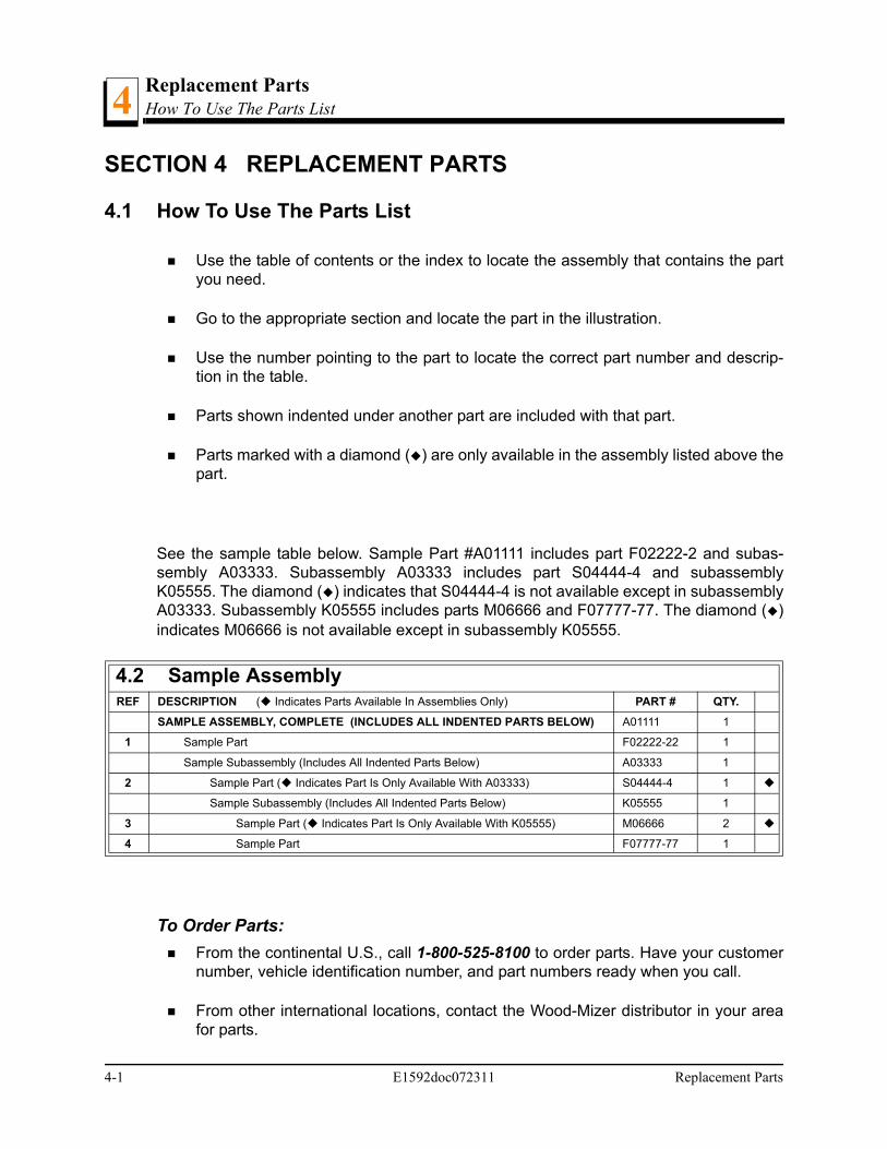
See the sample table below. Sample Part #A01111 includes part F02222-2 and subas-sembly A03333. Subassembly A03333 includes part S04444-4 and subassemblyK05555. The diamond () indicates that S04444-4 is not available except in subassemblyA03333. Subassembly K05555 includes parts M06666 and F07777-77. The diamond ()indicates M06666 is not available except in subassembly K05555.
To Order Parts:
From the continental U.S., call 1-800-525-8100 to order parts. Have your customernumber, vehicle identification number, and part numbers ready when you call.
From other international locations, contact the Wood-Mizer distributor in your areafor parts.
4.2 Sample AssemblyREF DESCRIPTION ( Indicates Parts Available In Assemblies Only) PART # QTY.
SAMPLE ASSEMBLY, COMPLETE (INCLUDES ALL INDENTED PARTS BELOW) A01111 1
1 Sample Part F02222-22 1
Sample Subassembly (Includes All Indented Parts Below) A03333 1
2 Sample Part ( Indicates Part Is Only Available With A03333) S04444-4 1
Sample Subassembly (Includes All Indented Parts Below) K05555 1
3 Sample Part ( Indicates Part Is Only Available With K05555) M06666 2
4 Sample Part F07777-77 1
4-1 E1592doc072311 Replacement Parts
Replacement PartsMotor Starter Assembly 4
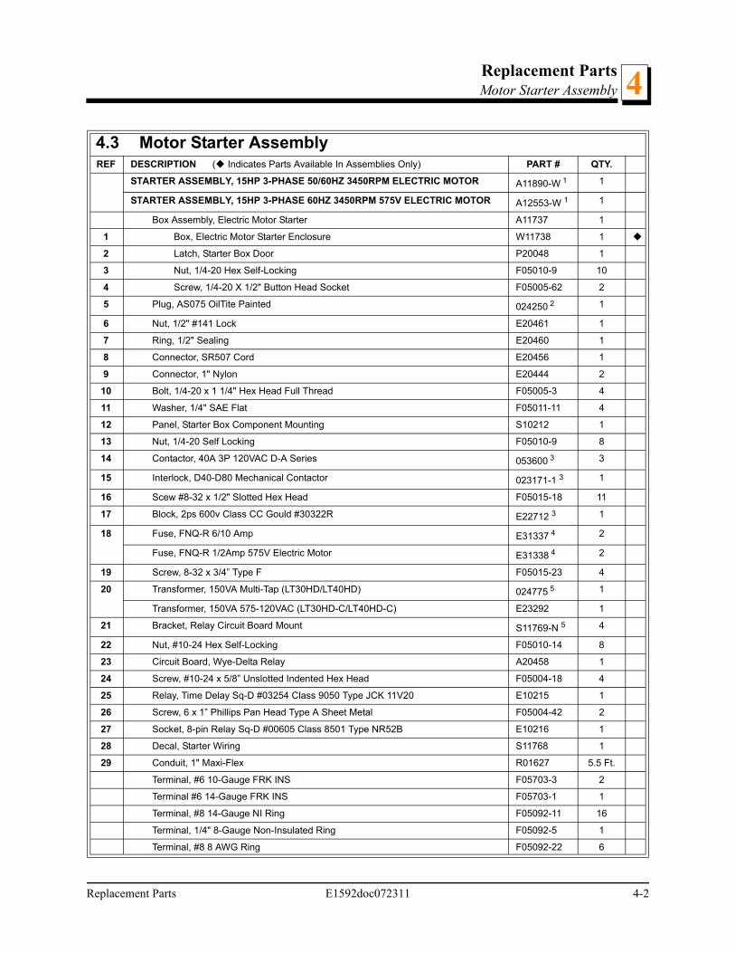
4.3 Motor Starter AssemblyREF DESCRIPTION ( Indicates Parts Available In Assemblies Only) PART # QTY.
STARTER ASSEMBLY, 15HP 3-PHASE 50/60HZ 3450RPM ELECTRIC MOTOR A11890-W 1 1
STARTER ASSEMBLY, 15HP 3-PHASE 60HZ 3450RPM 575V ELECTRIC MOTOR A12553-W 1 1
Box Assembly, Electric Motor Starter A11737 1
1 Box, Electric Motor Starter Enclosure W11738 1
2 Latch, Starter Box Door P20048 1
3 Nut, 1/4-20 Hex Self-Locking F05010-9 10
4 Screw, 1/4-20 X 1/2" Button Head Socket F05005-62 2
5 Plug, AS075 OilTite Painted 024250 2 1
6 Nut, 1/2" #141 Lock E20461 1
7 Ring, 1/2" Sealing E20460 1
8 Connector, SR507 Cord E20456 1
9 Connector, 1" Nylon E20444 2
10 Bolt, 1/4-20 x 1 1/4" Hex Head Full Thread F05005-3 4
11 Washer, 1/4" SAE Flat F05011-11 4
12 Panel, Starter Box Component Mounting S10212 1
13 Nut, 1/4-20 Self Locking F05010-9 8
14 Contactor, 40A 3P 120VAC D-A Series 053600 3 3
15 Interlock, D40-D80 Mechanical Contactor 023171-1 3 1
16 Scew #8-32 x 1/2" Slotted Hex Head F05015-18 11
17 Block, 2ps 600v Class CC Gould #30322R E22712 3 1
18 Fuse, FNQ-R 6/10 Amp E31337 4 2
Fuse, FNQ-R 1/2Amp 575V Electric Motor E31338 4 2
19 Screw, 8-32 x 3/4” Type F F05015-23 4
20 Transformer, 150VA Multi-Tap (LT30HD/LT40HD) 024775 5 1
Transformer, 150VA 575-120VAC (LT30HD-C/LT40HD-C) E23292 1
21 Bracket, Relay Circuit Board Mount S11769-N 5 4
22 Nut, #10-24 Hex Self-Locking F05010-14 8
23 Circuit Board, Wye-Delta Relay A20458 1
24 Screw, #10-24 x 5/8” Unslotted Indented Hex Head F05004-18 4
25 Relay, Time Delay Sq-D #03254 Class 9050 Type JCK 11V20 E10215 1
26 Screw, 6 x 1” Phillips Pan Head Type A Sheet Metal F05004-42 2
27 Socket, 8-pin Relay Sq-D #00605 Class 8501 Type NR52B E10216 1
28 Decal, Starter Wiring S11768 1
29 Conduit, 1" Maxi-Flex R01627 5.5 Ft.
Terminal, #6 10-Gauge FRK INS F05703-3 2
Terminal #6 14-Gauge FRK INS F05703-1 1
Terminal, #8 14-Gauge NI Ring F05092-11 16
Terminal, 1/4" 8-Gauge Non-Insulated Ring F05092-5 1
Terminal, #8 8 AWG Ring F05092-22 6
Replacement Parts E1592doc072311 4-2
Replacement PartsMotor Starter Assembly4
Terminal, #8 12-Gauge NI Ring F05092-12 1
Tie Wrap, .100" x 4" F05089-2 12
Anchor, Wire Tie, ADHB F05089-9 2
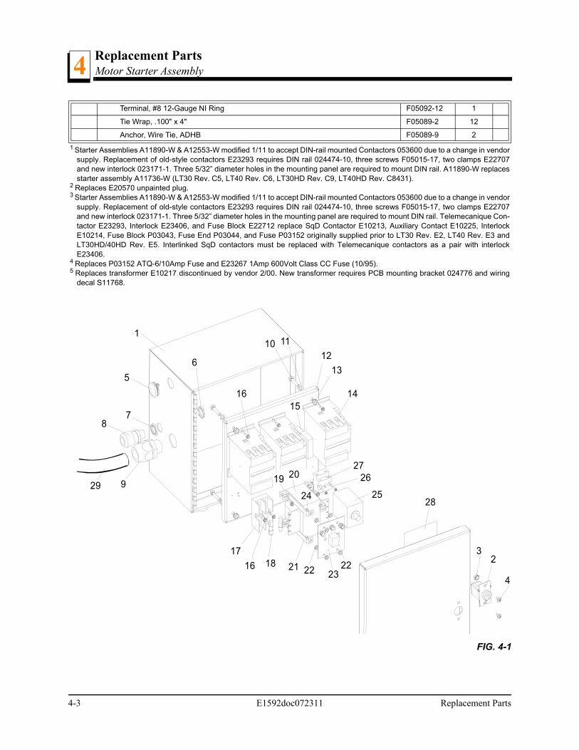
1 Starter Assemblies A11890-W & A12553-W modified 1/11 to accept DIN-rail mounted Contactors 053600 due to a change in vendorsupply. Replacement of old-style contactors E23293 requires DIN rail 024474-10, three screws F05015-17, two clamps E22707and new interlock 023171-1. Three 5/32” diameter holes in the mounting panel are required to mount DIN rail. A11890-W replacesstarter assembly A11736-W (LT30 Rev. C5, LT40 Rev. C6, LT30HD Rev. C9, LT40HD Rev. C8431).
2 Replaces E20570 unpainted plug.3 Starter Assemblies A11890-W & A12553-W modified 1/11 to accept DIN-rail mounted Contactors 053600 due to a change in vendor
supply. Replacement of old-style contactors E23293 requires DIN rail 024474-10, three screws F05015-17, two clamps E22707and new interlock 023171-1. Three 5/32” diameter holes in the mounting panel are required to mount DIN rail. Telemecanique Con-tactor E23293, Interlock E23406, and Fuse Block E22712 replace SqD Contactor E10213, Auxiliary Contact E10225, InterlockE10214, Fuse Block P03043, Fuse End P03044, and Fuse P03152 originally supplied prior to LT30 Rev. E2, LT40 Rev. E3 andLT30HD/40HD Rev. E5. Interlinked SqD contactors must be replaced with Telemecanique contactors as a pair with interlockE23406.
4 Replaces P03152 ATQ-6/10Amp Fuse and E23267 1Amp 600Volt Class CC Fuse (10/95).5 Replaces transformer E10217 discontinued by vendor 2/00. New transformer requires PCB mounting bracket 024776 and wiring
decal S11768.
FIG. 4-1
1
1415
23
24
22
25
2627
3
28
2
4
513
16
22
612
11
17
21
7
10
16
20
8
929
18
19
4-3 E1592doc072311 Replacement Parts
Replacement PartsMotor Assembly 4
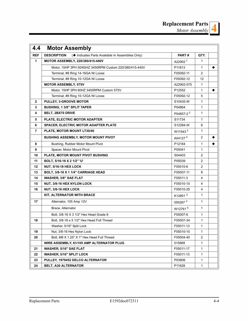
4.4 Motor AssemblyREF DESCRIPTION ( Indicates Parts Available In Assemblies Only) PART # QTY.
1 MOTOR ASSEMBLY, 220/380/415-440V A22902 1 1
Motor, 15HP 3PH 50/60HZ 3450RPM Custom 220/380/415-440V P11813 1
Terminal, #8 Ring 14-16GA NI Loose F05092-11 2
Terminal, #8 Ring 10-12GA NI Loose F05092-12 12
MOTOR ASSEMBLY, 575V A22902-575 1
Motor, 15HP 3PH 60HZ 3450RPM Custom 575V P12552 1
Terminal, #8 Ring 10-12GA NI Loose F05092-12 5
2 PULLEY, 3-GROOVE MOTOR S10435-W 1
3 BUSHING, 1 3/8" SPLIT TAPER P04864 1
4 BELT, 2BX70 DRIVE P04857-2 2 1
5 PLATE, ELECTRIC MOTOR ADAPTER S11734 1
6 SPACER, ELECTRIC MOTOR ADAPTER PLATE S12284-W 8
7 PLATE, MOTOR MOUNT LT30/40 W11543 3 1
BUSHING ASSEMBLY, MOTOR MOUNT PIVOT A04127 4 2
8 Bushing, Rubber Motor Mount Pivot P12164 1
9 Spacer, Motor Mount Pivot P05041 1
10 PLATE, MOTOR MOUNT PIVOT BUSHING S04403 2
11 BOLT, 5/16-18 X 2 1/2" 'U' P05039 2
12 NUT, 5/16-18 HEX LOCK F05010-6 2
13 BOLT, 3/8-16 X 1 1/4" CARRIAGE HEAD F05007-11 8
14 WASHER, 3/8" SAE FLAT F05011-3 4
15 NUT, 3/8-16 HEX NYLON LOCK F05010-10 4
16 NUT, 3/8-16 HEX LOCK F05010-25 4
KIT, ALTERNATOR WITH BRACE K12801 3 1
17 Alternator, 105 Amp 12V 050287 3 1
Brace, Alternator W12761 5 1
Bolt, 3/8-16 X 3 1/2" Hex Head Grade 8 F05007-6 1
18 Bolt, 3/8-16 x 5 1/2" Hex Head Full Thread F05007-34 1
Washer, 5/16" Split Lock F05011-13 1
19 Nut, 3/8-16 Hex Nylon Lock F05010-10 1
20 Bolt, M8 X 1.25" X 1" Hex Head Full Thread F05004-40 2
WIRE ASSEMBLY, 61/105 AMP ALTERNATOR PLUG 015969 1
21 WASHER, 5/16" SAE FLAT F05011-17 1
22 WASHER, 5/16" SPLIT LOCK F05011-13 1
23 PULLEY, 1979452 DELCO ALTERNATOR P03806 1
24 BELT, A30 ALTERNATOR P11628 1
Replacement Parts E1592doc072311 4-4
Replacement PartsMotor Assembly4
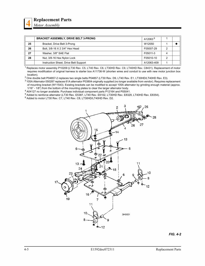
BRACKET ASSEMBLY, DRIVE BELT 3-PRONG A12063 6 1
25 Bracket, Drive Belt 3-Prong W12050 1
26 Bolt, 3/8-16 X 2 3/4" Hex Head F05007-29 2
27 Washer, 3/8" SAE Flat F05011-3 4
28 Nut, 3/8-16 Hex Nylon Lock F05010-10 2
Instruction Sheet, Drive Belt Support A12063-409 1
1 Replaces motor assembly P10209 (LT30 Rev. C5, LT40 Rev. C6, LT30HD Rev. C9, LT40HD Rev. C8431). Replacement of motorrequires modification of original harness to starter box A11736-W (shorten wires and conduit to use with new motor junction boxlocation).
2 One double belt P04857-2 replaces two single belts P04857 (LT30 Rev. D9, LT40 Rev. E1, LT30HD/LT40HD Rev. E3).3 105A Alternator 050287 replaces 61A alternator P03804 originally supplied (no longer available from vendor). Requires replacement
of mounting bracket (W11543). Existing brackets can be modified to accept 105A alternator by grinding enough material (approx.1/16” - 1/8”) from the bottom of the mounting plates to clear the larger alternator body.
4 A04127 no longer available. Purchase individual component parts P12164 and P05041.5 Added to reinforce alternator (LT30 Rev. E5387, LT40 Rev. E6102, LT30HD Rev. E8329, LT40HD Rev. E8354).6 Added to motor LT30 Rev. C7, LT40 Rev. C8, LT30HD/LT40HD Rev. D2.
FIG. 4-2
4-5 E1592doc072311 Replacement Parts

Electrical InformationElectrical Symbol Diagram, LT30/LT40 E155
SECTION 5 ELECTRICAL INFORMATION
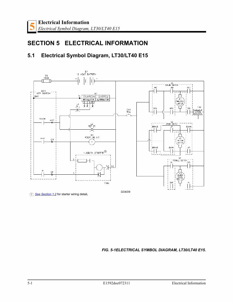
5.1 Electrical Symbol Diagram, LT30/LT40 E15
FIG. 5-1ELECTRICAL SYMBOL DIAGRAM, LT30/LT40 E15.
See Section 1.2 for starter wiring detail
5-1 E1592doc072311 Electrical Information
Electrical InformationElectrical Symbol Diagram, LT30/LT40 E15s 5
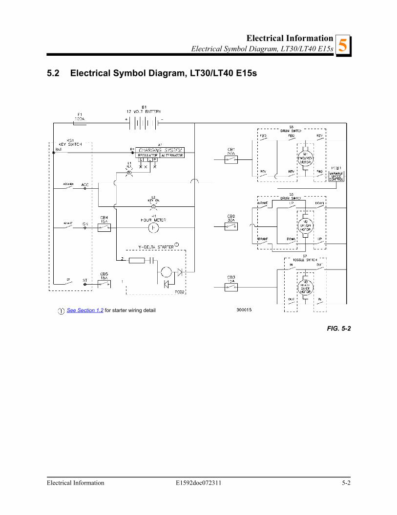
5.2 Electrical Symbol Diagram, LT30/LT40 E15s
FIG. 5-2
See Section 1.2 for starter wiring detail
Electrical Information E1592doc072311 5-2

Electrical InformationElectrical Symbol Diagram, LT30HD/LT40HD E15 (Rev. C7 - E6)5
5.3 Electrical Symbol Diagram, LT30HD/LT40HD E15 (Rev. C7 - E6)
FIG. 5-3
See Section 1.2 for starter wiring detail
5-3 E1592doc072311 Electrical Information
Electrical InformationElectrical Symbol Diagram, LT30HD/LT40HD E15 (Rev. E7-F7) 5
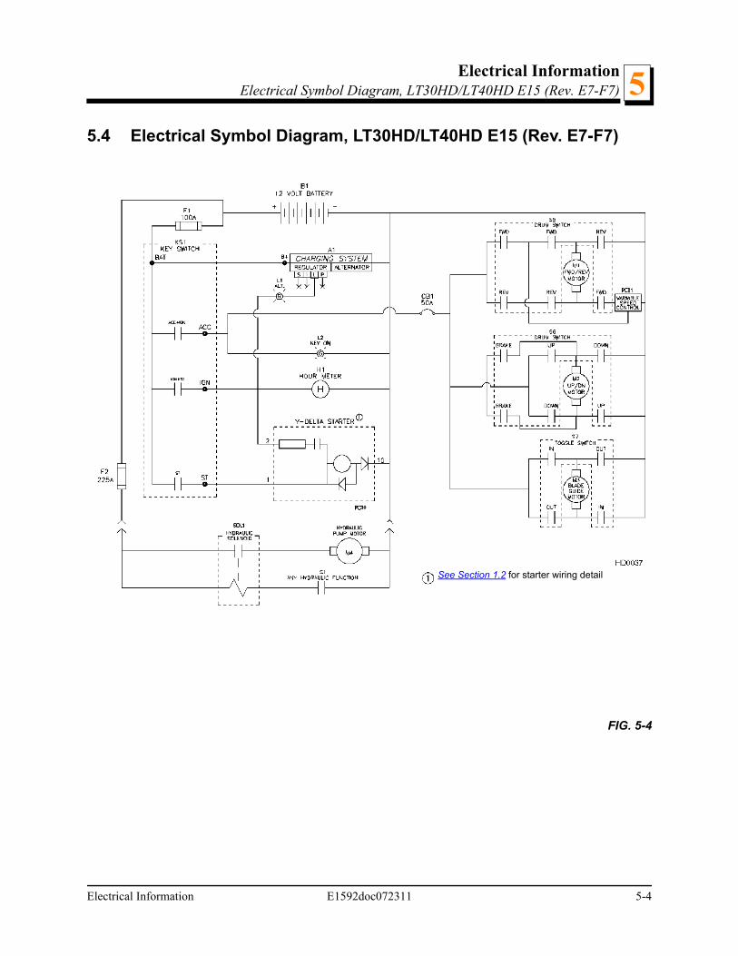
5.4 Electrical Symbol Diagram, LT30HD/LT40HD E15 (Rev. E7-F7)
FIG. 5-4
See Section 1.2 for starter wiring detail
Electrical Information E1592doc072311 5-4

Electrical InformationElectrical Symbol Diagram, LT30HD/LT40HD E15s (Rev. C7-E6)5
5.5 Electrical Symbol Diagram, LT30HD/LT40HD E15s (Rev. C7-E6)
FIG. 5-5
See Section 1.2 for starter wiring detail
5-5 E1592doc072311 Electrical Information
Electrical InformationElectrical Symbol Diagram, LT30HD/LT40HD E15s (Rev. E7-F7) 5
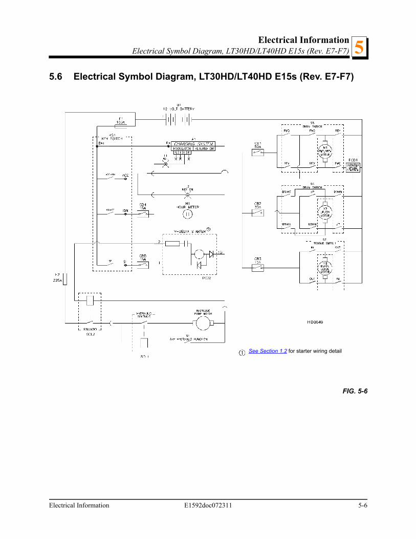
5.6 Electrical Symbol Diagram, LT30HD/LT40HD E15s (Rev. E7-F7)
FIG. 5-6
See Section 1.2 for starter wiring detail
Electrical Information E1592doc072311 5-6
Electrical InformationElectrical Components, LT30/LT40 E15/E15s5
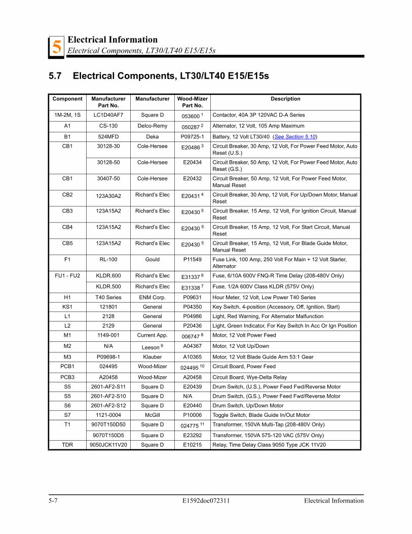
5.7 Electrical Components, LT30/LT40 E15/E15s
Component Manufacturer Part No.
Manufacturer Wood-Mizer Part No.
Description
1M-2M, 1S LC1D40AF7 Square D 053600 1 Contactor, 40A 3P 120VAC D-A Series
A1 CS-130 Delco-Remy 050287 2 Alternator, 12 Volt, 105 Amp Maximum
B1 524MFD Deka P09725-1 Battery, 12 Volt LT30/40 (See Section 5.10)
CB1 30128-30 Cole-Hersee E20486 3 Circuit Breaker, 30 Amp, 12 Volt, For Power Feed Motor, Auto Reset (U.S.)
30128-50 Cole-Hersee E20434 Circuit Breaker, 50 Amp, 12 Volt, For Power Feed Motor, Auto Reset (G.S.)
CB1 30407-50 Cole-Hersee E20432 Circuit Breaker, 50 Amp, 12 Volt, For Power Feed Motor, Manual Reset
CB2 123A30A2 Richard’s Elec E20431 4 Circuit Breaker, 30 Amp, 12 Volt, For Up/Down Motor, Manual Reset
CB3 123A15A2 Richard’s Elec E20430 5 Circuit Breaker, 15 Amp, 12 Volt, For Ignition Circuit, Manual Reset
CB4 123A15A2 Richard’s Elec E20430 5 Circuit Breaker, 15 Amp, 12 Volt, For Start Circuit, Manual Reset
CB5 123A15A2 Richard’s Elec E20430 5 Circuit Breaker, 15 Amp, 12 Volt, For Blade Guide Motor, Manual Reset
F1 RL-100 Gould P11549 Fuse Link, 100 Amp, 250 Volt For Main + 12 Volt Starter, Alternator
FU1 - FU2 KLDR.600 Richard’s Elec E31337 6 Fuse, 6/10A 600V FNQ-R Time Delay (208-480V Only)
KLDR.500 Richard’s Elec E31338 7 Fuse, 1/2A 600V Class KLDR (575V Only)
H1 T40 Series ENM Corp. P09631 Hour Meter, 12 Volt, Low Power T40 Series
KS1 121801 General P04350 Key Switch, 4-position (Accessory, Off, Ignition, Start)
L1 2128 General P04986 Light, Red Warning, For Alternator Malfunction
L2 2129 General P20436 Light, Green Indicator, For Key Switch In Acc Or Ign Position
M1 1149-001 Current App. 006747 8 Motor, 12 Volt Power Feed
M2 N/A Leeson 9 A04367 Motor, 12 Volt Up/Down
M3 P09698-1 Klauber A10365 Motor, 12 Volt Blade Guide Arm 53:1 Gear
PCB1 024495 Wood-Mizer 024495 10 Circuit Board, Power Feed
PCB3 A20458 Wood-Mizer A20458 Circuit Board, Wye-Delta Relay
S5 2601-AF2-S11 Square D E20439 Drum Switch, (U.S.), Power Feed Fwd/Reverse Motor
S5 2601-AF2-S10 Square D N/A Drum Switch, (G.S.), Power Feed Fwd/Reverse Motor
S6 2601-AF2-S12 Square D E20440 Drum Switch, Up/Down Motor
S7 1121-0004 McGill P10006 Toggle Switch, Blade Guide In/Out Motor
T1 9070T150D50 Square D 024775 11 Transformer, 150VA Multi-Tap (208-480V Only)
9070T150D5 Square D E23292 Transformer, 150VA 575-120 VAC (575V Only)
TDR 9050JCK11V20 Square D E10215 Relay, Time Delay Class 9050 Type JCK 11V20
5-7 E1592doc072311 Electrical Information
Electrical InformationElectrical Components, LT30/LT40 E15/E15s 5
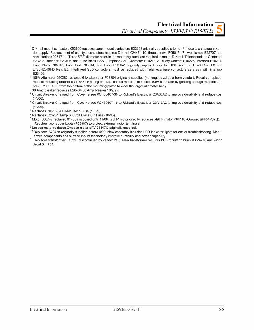
1 DIN rail-mount contactors 053600 replaces panel-mount contactors E23293 originally supplied prior to 1/11 due to a change in ven-dor supply. Replacement of old-style contactors requires DIN rail 024474-10, three screws F05015-17, two clamps E22707 andnew interlock 023171-1. Three 5/32” diameter holes in the mounting panel are required to mount DIN rail. Telemecanique ContactorE23293, Interlock E23406, and Fuse Block E22712 replace SqD Contactor E10213, Auxiliary Contact E10225, Interlock E10214,Fuse Block P03043, Fuse End P03044, and Fuse P03152 originally supplied prior to LT30 Rev. E2, LT40 Rev. E3 andLT30HD/40HD Rev. E5. Interlinked SqD contactors must be replaced with Telemecanique contactors as a pair with interlockE23406.
2 105A Alternator 050287 replaces 61A alternator P03804 originally supplied (no longer available from vendor). Requires replace-ment of mounting bracket (W11543). Existing brackets can be modified to accept 105A alternator by grinding enough material (ap-prox. 1/16” - 1/8”) from the bottom of the mounting plates to clear the larger alternator body.
3 30 Amp breaker replaces E20434 50 Amp breaker 10/9/95.4 Circuit Breaker Changed from Cole-Hersee #CH30407-30 to Richard’s Electric #123A30A2 to improve durability and reduce cost
(11/06).5 Circuit Breaker Changed from Cole-Hersee #CH30407-15 to Richard’s Electric #123A15A2 to improve durability and reduce cost
(11/06).6 Replaces P03152 ATQ-6/10Amp Fuse (10/95).7 Replaces E23267 1Amp 600Volt Class CC Fuse (10/95).8 Motor 006747 replaced 014359 supplied until 11/08. .25HP motor directly replaces .49HP motor P04140 (Owosso #PR-4P07Q).
Requires two rubber boots (P03807) to protect external motor terminals.9 Leeson motor replaces Owooso motor #PV-28147Q originally supplied.10 Replaces A20428 originally supplied before 4/99. New assembly includes LED indicator lights for easier troubleshooting. Modu-
larized components and surface mount technology improve durability and power capability.11 Replaces transformer E10217 discontinued by vendor 2/00. New transformer requires PCB mounting bracket 024776 and wiring
decal S11768.
Electrical Information E1592doc072311 5-8
Electrical InformationElectrical Components, LT30HD/LT40HD E15/E15s (Rev. C7 - E6)5
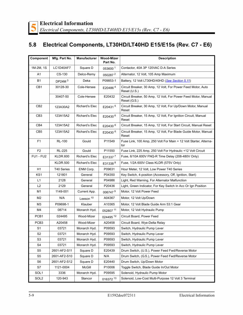
5.8 Electrical Components, LT30HD/LT40HD E15/E15s (Rev. C7 - E6)
Component Mfg. Part No. Manufacturer Wood-Mizer Part No.
Description
1M-2M, 1S LC1D40AF7 Square D 053600 1 Contactor, 40A 3P 120VAC D-A Series
A1 CS-130 Delco-Remy 050287 2 Alternator, 12 Volt, 105 Amp Maximum
B1 DP24M 3 Deka P09853-1 Battery, 12 Volt LT30HD/40HD (See Section 5.11)
CB1 30128-30 Cole-Hersee E20486 4 Circuit Breaker, 30 Amp, 12 Volt, For Power Feed Motor, Auto Reset (U.S.)
30407-50 Cole-Hersee E20432 Circuit Breaker, 50 Amp, 12 Volt, For Power Feed Motor, Manual Reset (G.S.)
CB2 123A30A2 Richard’s Elec E20431 5 Circuit Breaker, 30 Amp, 12 Volt, For Up/Down Motor, Manual Reset
CB3 123A15A2 Richard’s Elec E20430 6 Circuit Breaker, 15 Amp, 12 Volt, For Ignition Circuit, Manual Reset
CB4 123A15A2 Richard’s Elec E20430 6 Circuit Breaker, 15 Amp, 12 Volt, For Start Circuit, Manual Reset
CB5 123A15A2 Richard’s Elec E20430 6 Circuit Breaker, 15 Amp, 12 Volt, For Blade Guide Motor, Manual Reset
F1 RL-100 Gould P11549 Fuse Link, 100 Amp, 250 Volt For Main + 12 Volt Starter, Alterna-tor
F2 RL-225 Gould P11550 Fuse Link, 225 Amp, 250 Volt For Hydraulic +12 Volt Circuit
FU1 - FU2 KLDR.600 Richard’s Elec E31337 7 Fuse, 6/10A 600V FNQ-R Time Delay (208-480V Only)
KLDR.500 Richard’s Elec E31338 8 Fuse, 1/2A 600V Class KLDR (575V Only)
H1 T40 Series ENM Corp. P09631 Hour Meter, 12 Volt, Low Power T40 Series
KS1 121801 General P04350 Key Switch, 4-position (Accessory, Off, Ignition, Start)
L1 2128 General P04986 Light, Red Warning, For Alternator Malfunction
L2 2129 General P20436 Light, Green Indicator, For Key Switch In Acc Or Ign Position
M1 1149-001 Current App. 006747 9 Motor, 12 Volt Power Feed
M2 N/A Leeson 10 A04367 Motor, 12 Volt Up/Down
M3 P09698-1 Klauber A10365 Motor, 12 Volt Blade Guide Arm 53:1 Gear
M4 08714 Monarch Hyd. 052807 11 Motor, 12 Volt Hydraulic Pump
PCB1 024495 Wood-Mizer 024495 12 Circuit Board, Power Feed
PCB3 A20458 Wood-Mizer A20458 Circuit Board, Wye-Delta Relay
S1 03721 Monarch Hyd. P09593 Switch, Hydraulic Pump Lever
S2 03721 Monarch Hyd. P09593 Switch, Hydraulic Pump Lever
S3 03721 Monarch Hyd. P09593 Switch, Hydraulic Pump Lever
S4 03721 Monarch Hyd. P09593 Switch, Hydraulic Pump Lever
S5 2601-AF2-S11 Square D E20439 Drum Switch, (U.S.), Power Feed Fwd/Reverse Motor
S5 2601-AF2-S10 Square D N/A Drum Switch, (G.S.), Power Feed Fwd/Reverse Motor
S6 2601-AF2-S12 Square D E20440 Drum Switch, Up/Down Motor
S7 1121-0004 McGill P10006 Toggle Switch, Blade Guide In/Out Motor
SOL1 3336 Monarch Hyd. P09595 Solenoid, Hydraulic Pump Motor
SOL2 120-943 Stancor 016372 13 Solenoid, Low-Cost Multi-Purpose 12 Volt 3 Terminal
5-9 E1592doc072311 Electrical Information
Electrical InformationElectrical Components, LT30HD/LT40HD E15/E15s (Rev. C7 - E6) 5
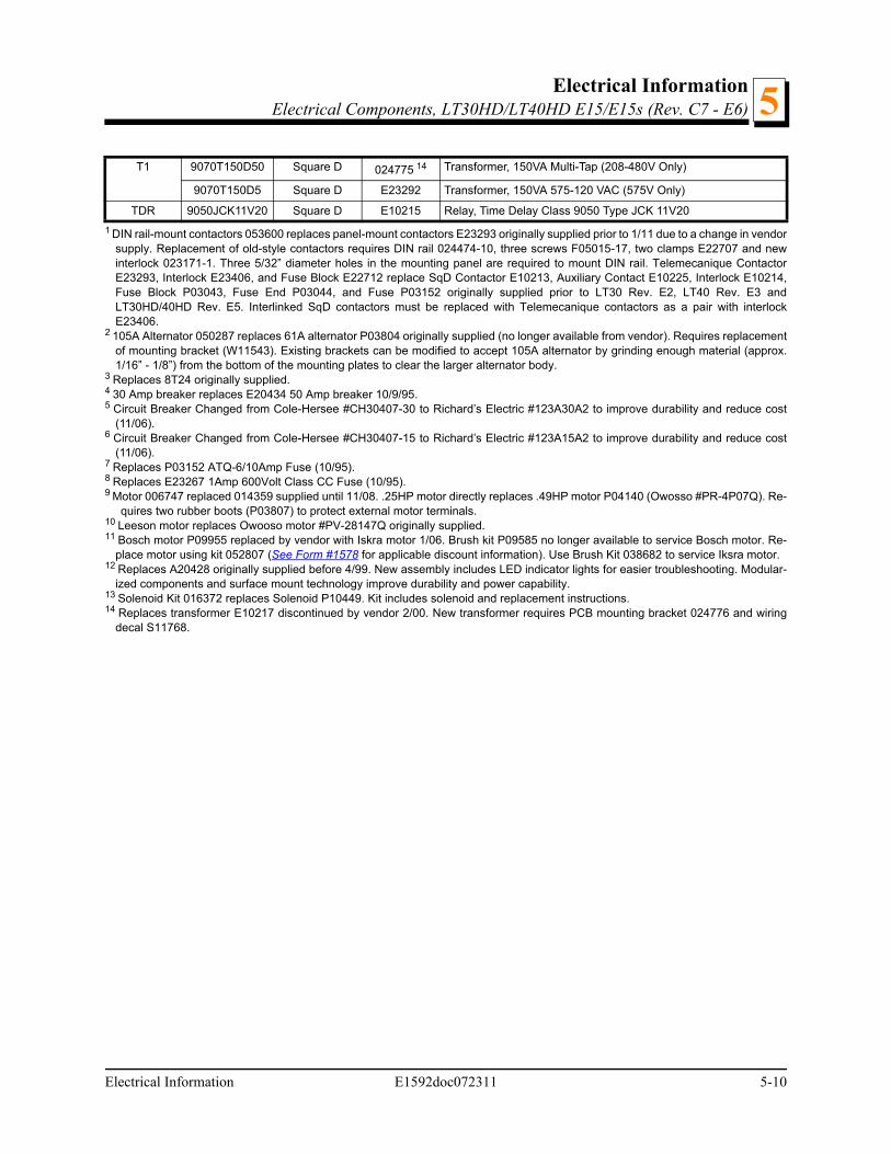
T1 9070T150D50 Square D 024775 14 Transformer, 150VA Multi-Tap (208-480V Only)
9070T150D5 Square D E23292 Transformer, 150VA 575-120 VAC (575V Only)
TDR 9050JCK11V20 Square D E10215 Relay, Time Delay Class 9050 Type JCK 11V20
1 DIN rail-mount contactors 053600 replaces panel-mount contactors E23293 originally supplied prior to 1/11 due to a change in vendorsupply. Replacement of old-style contactors requires DIN rail 024474-10, three screws F05015-17, two clamps E22707 and newinterlock 023171-1. Three 5/32” diameter holes in the mounting panel are required to mount DIN rail. Telemecanique ContactorE23293, Interlock E23406, and Fuse Block E22712 replace SqD Contactor E10213, Auxiliary Contact E10225, Interlock E10214,Fuse Block P03043, Fuse End P03044, and Fuse P03152 originally supplied prior to LT30 Rev. E2, LT40 Rev. E3 andLT30HD/40HD Rev. E5. Interlinked SqD contactors must be replaced with Telemecanique contactors as a pair with interlockE23406.
2 105A Alternator 050287 replaces 61A alternator P03804 originally supplied (no longer available from vendor). Requires replacementof mounting bracket (W11543). Existing brackets can be modified to accept 105A alternator by grinding enough material (approx.1/16” - 1/8”) from the bottom of the mounting plates to clear the larger alternator body.
3 Replaces 8T24 originally supplied.4 30 Amp breaker replaces E20434 50 Amp breaker 10/9/95.5 Circuit Breaker Changed from Cole-Hersee #CH30407-30 to Richard’s Electric #123A30A2 to improve durability and reduce cost
(11/06).6 Circuit Breaker Changed from Cole-Hersee #CH30407-15 to Richard’s Electric #123A15A2 to improve durability and reduce cost
(11/06).7 Replaces P03152 ATQ-6/10Amp Fuse (10/95).8 Replaces E23267 1Amp 600Volt Class CC Fuse (10/95).9 Motor 006747 replaced 014359 supplied until 11/08. .25HP motor directly replaces .49HP motor P04140 (Owosso #PR-4P07Q). Re-
quires two rubber boots (P03807) to protect external motor terminals.10 Leeson motor replaces Owooso motor #PV-28147Q originally supplied.11 Bosch motor P09955 replaced by vendor with Iskra motor 1/06. Brush kit P09585 no longer available to service Bosch motor. Re-
place motor using kit 052807 (See Form #1578 for applicable discount information). Use Brush Kit 038682 to service Iksra motor.12 Replaces A20428 originally supplied before 4/99. New assembly includes LED indicator lights for easier troubleshooting. Modular-
ized components and surface mount technology improve durability and power capability.13 Solenoid Kit 016372 replaces Solenoid P10449. Kit includes solenoid and replacement instructions.14 Replaces transformer E10217 discontinued by vendor 2/00. New transformer requires PCB mounting bracket 024776 and wiring
decal S11768.
Electrical Information E1592doc072311 5-10
Electrical InformationElectrical Components, LT30HD/LT40HD E15/E15s (Rev. E7+)5
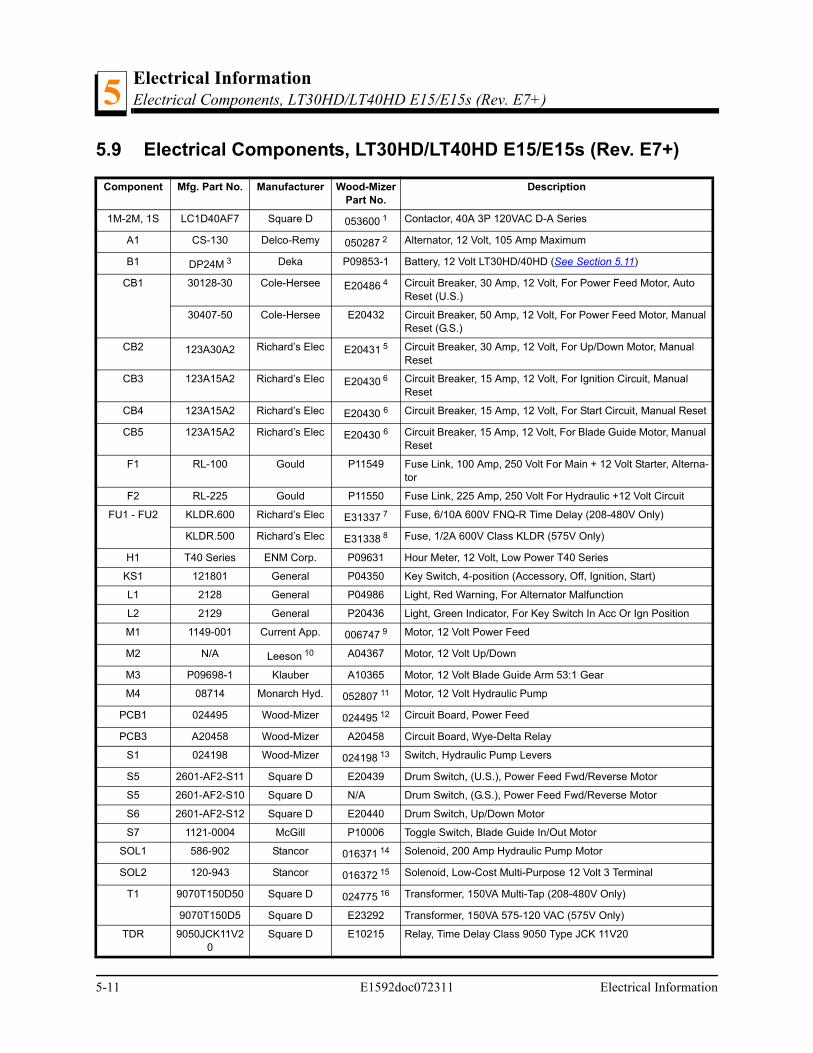
5.9 Electrical Components, LT30HD/LT40HD E15/E15s (Rev. E7+)
Component Mfg. Part No. Manufacturer Wood-Mizer Part No.
Description
1M-2M, 1S LC1D40AF7 Square D 053600 1 Contactor, 40A 3P 120VAC D-A Series
A1 CS-130 Delco-Remy 050287 2 Alternator, 12 Volt, 105 Amp Maximum
B1 DP24M 3 Deka P09853-1 Battery, 12 Volt LT30HD/40HD (See Section 5.11)
CB1 30128-30 Cole-Hersee E20486 4 Circuit Breaker, 30 Amp, 12 Volt, For Power Feed Motor, Auto Reset (U.S.)
30407-50 Cole-Hersee E20432 Circuit Breaker, 50 Amp, 12 Volt, For Power Feed Motor, Manual Reset (G.S.)
CB2 123A30A2 Richard’s Elec E20431 5 Circuit Breaker, 30 Amp, 12 Volt, For Up/Down Motor, Manual Reset
CB3 123A15A2 Richard’s Elec E20430 6 Circuit Breaker, 15 Amp, 12 Volt, For Ignition Circuit, Manual Reset
CB4 123A15A2 Richard’s Elec E20430 6 Circuit Breaker, 15 Amp, 12 Volt, For Start Circuit, Manual Reset
CB5 123A15A2 Richard’s Elec E20430 6 Circuit Breaker, 15 Amp, 12 Volt, For Blade Guide Motor, Manual Reset
F1 RL-100 Gould P11549 Fuse Link, 100 Amp, 250 Volt For Main + 12 Volt Starter, Alterna-tor
F2 RL-225 Gould P11550 Fuse Link, 225 Amp, 250 Volt For Hydraulic +12 Volt Circuit
FU1 - FU2 KLDR.600 Richard’s Elec E31337 7 Fuse, 6/10A 600V FNQ-R Time Delay (208-480V Only)
KLDR.500 Richard’s Elec E31338 8 Fuse, 1/2A 600V Class KLDR (575V Only)
H1 T40 Series ENM Corp. P09631 Hour Meter, 12 Volt, Low Power T40 Series
KS1 121801 General P04350 Key Switch, 4-position (Accessory, Off, Ignition, Start)
L1 2128 General P04986 Light, Red Warning, For Alternator Malfunction
L2 2129 General P20436 Light, Green Indicator, For Key Switch In Acc Or Ign Position
M1 1149-001 Current App. 006747 9 Motor, 12 Volt Power Feed
M2 N/A Leeson 10 A04367 Motor, 12 Volt Up/Down
M3 P09698-1 Klauber A10365 Motor, 12 Volt Blade Guide Arm 53:1 Gear
M4 08714 Monarch Hyd. 052807 11 Motor, 12 Volt Hydraulic Pump
PCB1 024495 Wood-Mizer 024495 12 Circuit Board, Power Feed
PCB3 A20458 Wood-Mizer A20458 Circuit Board, Wye-Delta Relay
S1 024198 Wood-Mizer 024198 13 Switch, Hydraulic Pump Levers
S5 2601-AF2-S11 Square D E20439 Drum Switch, (U.S.), Power Feed Fwd/Reverse Motor
S5 2601-AF2-S10 Square D N/A Drum Switch, (G.S.), Power Feed Fwd/Reverse Motor
S6 2601-AF2-S12 Square D E20440 Drum Switch, Up/Down Motor
S7 1121-0004 McGill P10006 Toggle Switch, Blade Guide In/Out Motor
SOL1 586-902 Stancor 016371 14 Solenoid, 200 Amp Hydraulic Pump Motor
SOL2 120-943 Stancor 016372 15 Solenoid, Low-Cost Multi-Purpose 12 Volt 3 Terminal
T1 9070T150D50 Square D 024775 16 Transformer, 150VA Multi-Tap (208-480V Only)
9070T150D5 Square D E23292 Transformer, 150VA 575-120 VAC (575V Only)
TDR 9050JCK11V20
Square D E10215 Relay, Time Delay Class 9050 Type JCK 11V20
5-11 E1592doc072311 Electrical Information

Electrical InformationElectrical Components, LT30HD/LT40HD E15/E15s (Rev. E7+) 5
1 DIN rail-mount contactors 053600 replaces panel-mount contactors E23293 originally supplied prior to 1/11 due to a change in ven-dor supply. Replacement of old-style contactors requires DIN rail 024474-10, three screws F05015-17, two clamps E22707 andnew interlock 023171-1. Three 5/32” diameter holes in the mounting panel are required to mount DIN rail. Telemecanique ContactorE23293, Interlock E23406, and Fuse Block E22712 replace SqD Contactor E10213, Auxiliary Contact E10225, Interlock E10214,Fuse Block P03043, Fuse End P03044, and Fuse P03152 originally supplied prior to LT30 Rev. E2, LT40 Rev. E3 andLT30HD/40HD Rev. E5. Interlinked SqD contactors must be replaced with Telemecanique contactors as a pair with interlockE23406.
2 105A Alternator 050287 replaces 61A alternator P03804 originally supplied (no longer available from vendor). Requires replacementof mounting bracket (W11543). Existing brackets can be modified to accept 105A alternator by grinding enough material (approx.1/16” - 1/8”) from the bottom of the mounting plates to clear the larger alternator body.
3 Replaces 8T24 originally supplied.4 30 Amp breaker replaces E20434 50 Amp breaker 10/9/95.5 Circuit Breaker Changed from Cole-Hersee #CH30407-30 to Richard’s Electric #123A30A2 to improve durability and reduce cost
(11/06).6 Circuit Breaker Changed from Cole-Hersee #CH30407-15 to Richard’s Electric #123A15A2 to improve durability and reduce cost
(11/06).7 Replaces P03152 ATQ-6/10Amp Fuse (10/95).8 Replaces E23267 1Amp 600Volt Class CC Fuse (10/95).9 Motor 006747 replaced 014359 supplied until 11/08. .25HP motor directly replaces .49HP motor P04140 (Owosso #PR-4P07Q).
Requires two rubber boots (P03807) to protect external motor terminals.10 Leeson motor replaces Owooso motor #PV-28147Q originally supplied.11 Bosch motor P09955 replaced by vendor with Iskra motor 1/06. Brush kit P09585 no longer available to service Bosch motor. Re-
place motor using kit 052807 (See Form #1578 for applicable discount information). Use Brush Kit 038682 to service Iksra motor.12 Replaces A20428 originally supplied before 4/99. New assembly includes LED indicator lights for easier troubleshooting. Modular-
ized components and surface mount technology improve durability and power capability.13 Saleable service assembly created which includes 014765 3-wire switch and crimped terminals (7/97). 014765 3-wire switch di-
rectly replaces P12735 2-wire switch (4/97).14 Solenoid Kit 016371 replaces Solenoid 015470. Kit includes solenoid and replacement instructions. If replacing original P09595
100 amp solenoid, order retrofit kit 015783.15 Solenoid Kit 016372 replaces Solenoid P10449. Kit includes solenoid and replacement instructions.16 Replaces transformer E10217 discontinued by vendor 2/00. New transformer requires PCB mounting bracket 024776 and wiring
decal S11768.
Electrical Information E1592doc072311 5-12
Electrical InformationBattery Specifications, LT30/LT40 E15/E15s5
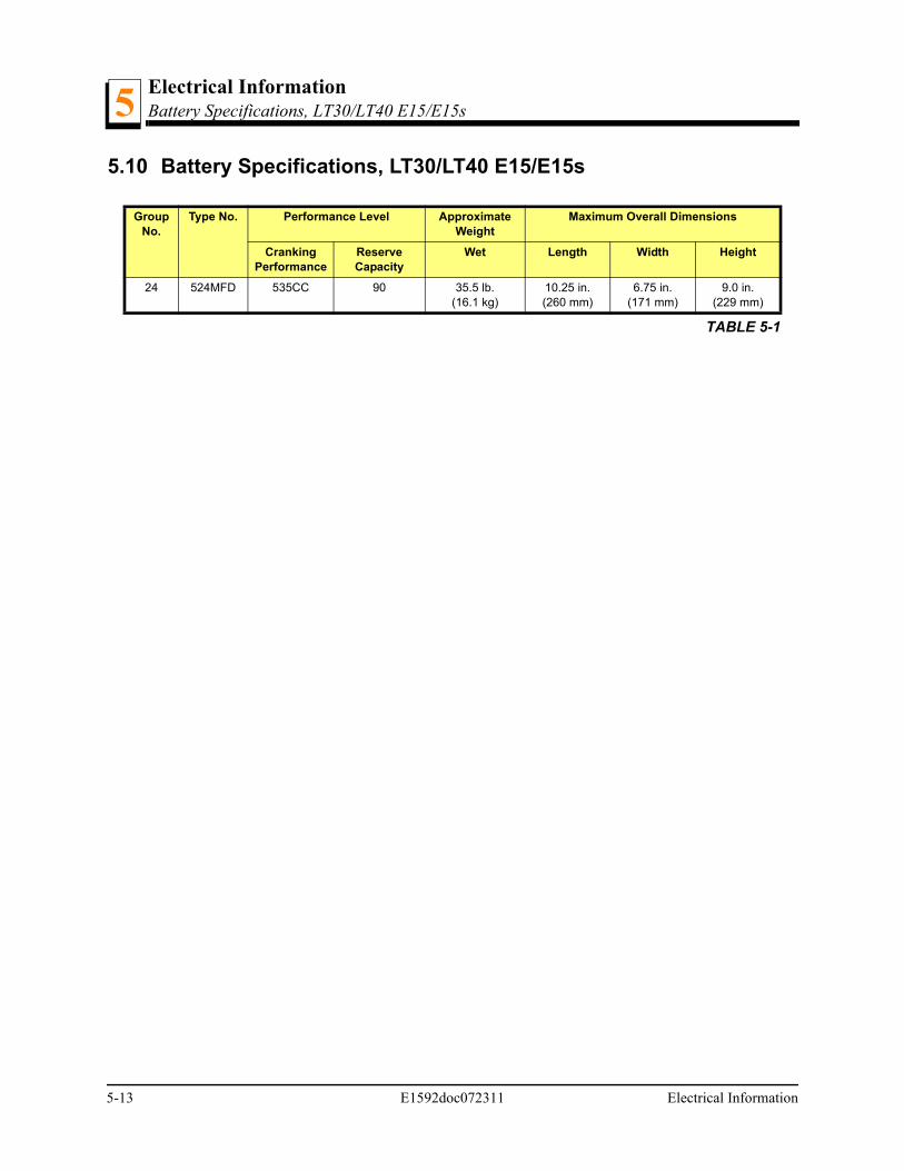
5.10 Battery Specifications, LT30/LT40 E15/E15s
Group No.
Type No. Performance Level Approximate Weight
Maximum Overall Dimensions
Cranking Performance
Reserve Capacity
Wet Length Width Height
24 524MFD 535CC 90 35.5 lb.(16.1 kg)
10.25 in.(260 mm)
6.75 in.(171 mm)
9.0 in.(229 mm)
TABLE 5-1
5-13 E1592doc072311 Electrical Information
Electrical InformationBattery Specifications, LT30HD/LT40HD E15/E15s 5
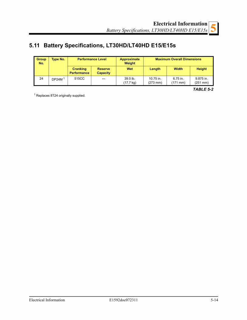
5.11 Battery Specifications, LT30HD/LT40HD E15/E15s
Group No.
Type No. Performance Level Approximate Weight
Maximum Overall Dimensions
Cranking Performance
Reserve Capacity
Wet Length Width Height
24 DP24M 1
1 Replaces 8T24 originally supplied.
515CC --- 39.0 lb.(17.7 kg)
10.75 in.(273 mm)
6.75 in.(171 mm)
9.875 in.(251 mm)
TABLE 5-2
Electrical Information E1592doc072311 5-14
Electrical InformationWiring Diagram, LT30/LT40 E155
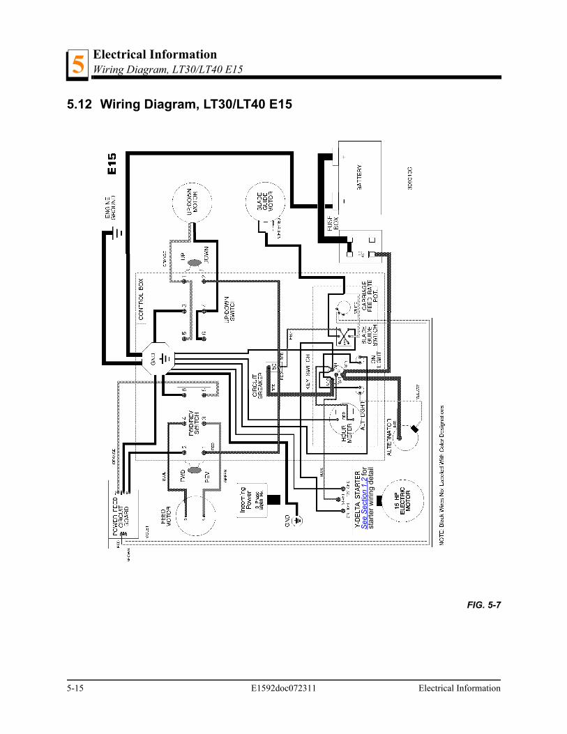
5.12 Wiring Diagram, LT30/LT40 E15
FIG. 5-7
See
Sec
tion
1.2
for
star
ter
wiri
ng
deta
il
5-15 E1592doc072311 Electrical Information
Electrical InformationWiring Diagram, LT30/LT40 E15s 5
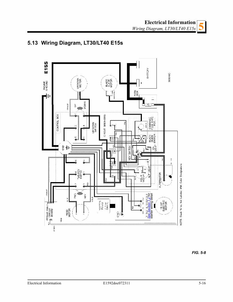
5.13 Wiring Diagram, LT30/LT40 E15s
FIG. 5-8
See
Sec
tion
1.2
for
star
ter
wiri
ng d
etai
l
Electrical Information E1592doc072311 5-16

Electrical InformationWiring Diagram, LT30HD/LT40HD E155
5.14 Wiring Diagram, LT30HD/LT40HD E15
FIG. 5-9
See
Sec
tion
1.2
for
star
ter
wiri
ng d
etai
l
5-17 E1592doc072311 Electrical Information
Electrical InformationWiring Diagram, LT30HD/LT40HD E15s 5
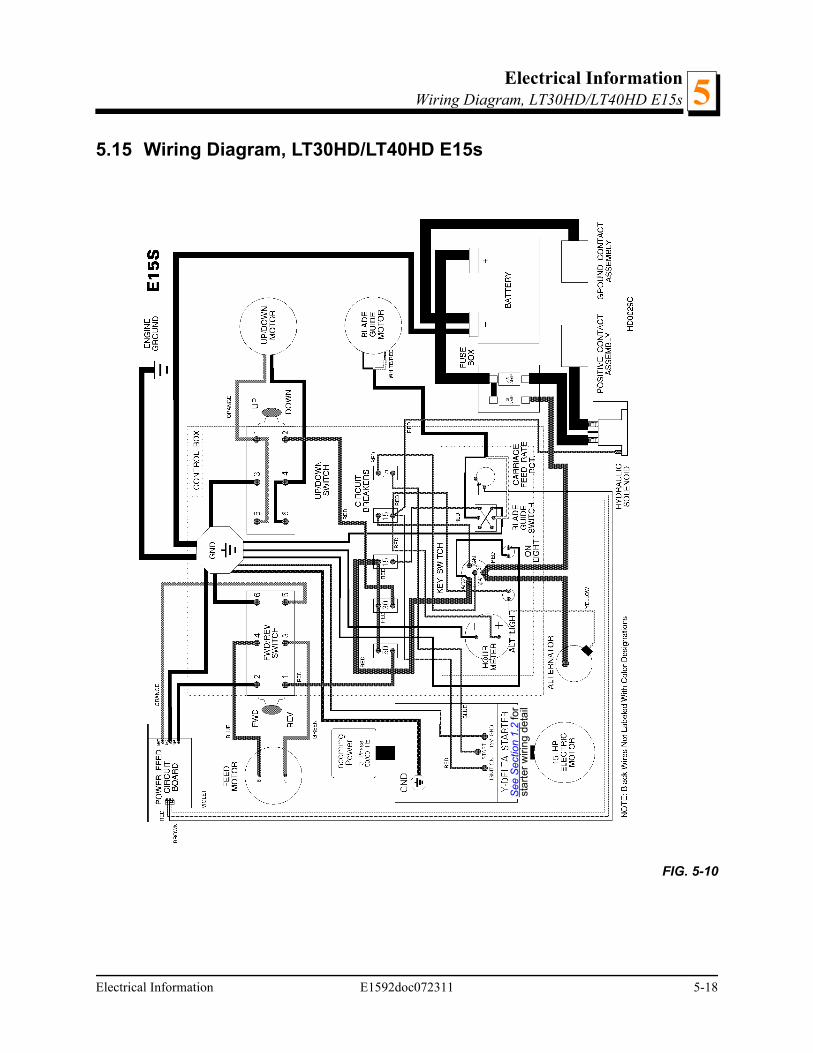
5.15 Wiring Diagram, LT30HD/LT40HD E15s
FIG. 5-10
See
Sec
tion
1.2
for
star
ter
wiri
ng d
etai
l
Electrical Information E1592doc072311 5-18
i E1592doc072311 Index
INDEX
A
alternator belt 3-2
B
battery handling 1-1
battery maintenance 3-1
battery specifications (LT30/LT40) 5-13
battery specifications (LT30HD/LT40HD) 5-14
beltalternator tension 3-2
E
electric sawmillphase converter service requirements 1-5
electrical components (LT30HD/LT40HD 5-9
electrical symbol diagram (LT30/LT40) 5-2
electrical symbol diagram (LT30HD/LT40HD) 5-3, 5-4,5-5, 5-6
M
maintenance 3-1
P
parts listhow to use 4-1
phase converter 1-5
R
replacement parts 4-1
S
safety information 1-1
schematics 5-1
service requirements 1-4
starting 2-1
W
wiring460 volt electric sawmill 1-2575 Volt electric sawmill 1-3
wiring diagram (LT30/LT40) 5-15, 5-16
wiring diagram (LT30HD/LT40HD) 5-17, 5-18